Embed Size (px)
Citation preview
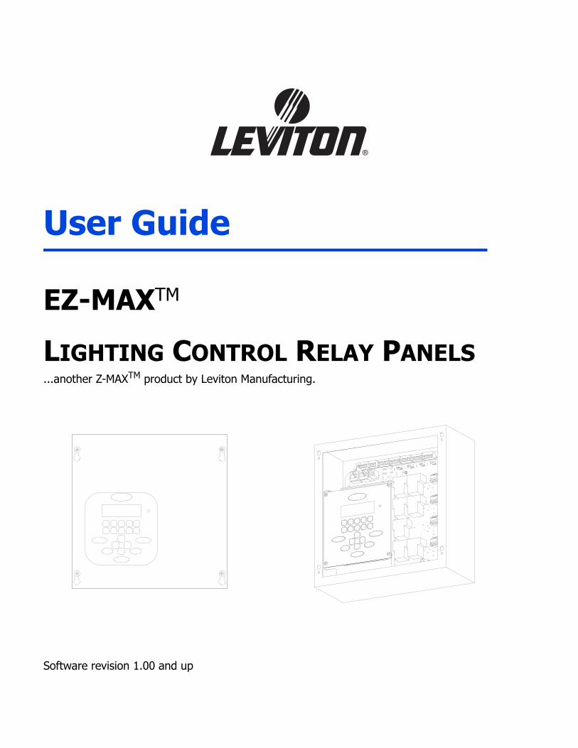
User Guide
EZ-MAXTM
LIGHTING CONTROL RELAY PANELS...another Z-MAXTM product by Leviton Manufacturing.
Software revision 1.00 and up

.

Table of Contents,
Table of Contents
OverviewInspection..................................................................................................... 1Description.................................................................................................... 1Control Overview ........................................................................................... 1Feed and Load Wiring .................................................................................... 2Control Input Wiring ...................................................................................... 2Turn On ........................................................................................................ 2
InstallationInstallation Checklist ...................................................................................... 5Mounting ...................................................................................................... 6
Suggested Mounting Heights: .................................................................... 7Location of cabinets .................................................................................. 8Mounting Cabinet ..................................................................................... 8
Feed and Load WiringOverview of Power Wiring - Feed\Line Wiring ................................................ 11Control Electronics Power Wiring................................................................... 13Line and Load Circuit Wiring ......................................................................... 13
Testing the Circuits ................................................................................. 13Wiring the relays .................................................................................... 14Circuit Schedule...................................................................................... 17
Low Voltage Control WiringControl Input Wiring .................................................................................... 19
Configuring Low Voltage Inputs ............................................................... 19Switch Input Schedule............................................................................. 21Low Voltage Input Terminals & Connections ............................................. 22Connecting Low Voltage Switches ............................................................ 25Occupancy Sensors................................................................................. 27Photocells .............................................................................................. 29Wiring with an External Power Supply ...................................................... 31
Power Considerations for Control Systems ..................................................... 33Terminology ........................................................................................... 33Power Requirements & Maximum Run Length........................................... 33Power Wire - Run Length ........................................................................ 36
Modem Installation/Phone Line Connection.................................................... 37Modem Module Installation...................................................................... 37
EZ-MAX User Guide Page i Revision A - April 2005
Table of Contents,
OperationLCD Display .................................................................................................39
Navigation Buttons ..................................................................................40Turning Relays On/Off & Relay Overrides..................................................41To Override a Relay On or Off ..................................................................41To Override a Relay On or Off for a specified time .....................................42
Determine the Firmware/Software Build.........................................................43Factory Defaults...........................................................................................45Setting the Date, Time, & Astronomical Time Clock.........................................47
Set the Date & Time................................................................................47Set the Astronomical Time Clock ..............................................................48
Configuration the Simple WayPanel Configuration in Simple Mode...............................................................51Simple Mode Menu Structure ........................................................................52Configure Inputs ..........................................................................................52
Low Voltage Switch Inputs.......................................................................53Photocell Configuration............................................................................54Occupancy Sensor Configuration ..............................................................57Quick Schedule .......................................................................................59
Advanced Mode Configuration
Limited Warranty ...................................................................................................67
Page ii

Overview, Inspection
Overview
InspectionCarefully unpack the relay cabinet, and inspect to make sure there has been no hiddenshipping damage. Report all damage to the freight carrier who delivered the system. Claimsfor damages are filed with the freight carrier as all freight is shipped FOB Tualatin, Oregon. In case of damaged components, your EZ-MAX relay cabinet can be serviced in the field withfactory replacement parts.
DescriptionThe compact physical design of your EZ-MAX Relay cabinet takes up a minimum of wall space.The product is only designed for surface mounting. The properties of your cabinet are asfollows:
Cabinet Properties
Some of the relay features are:• UL & cUL Listed for use in USA and Canada• Compliant with NEMA requirements• Easy to install• Quick & Easy to Configure
The control portion of the relay cabinet employs all digital circuitry for accuracy and forminimum wiring requirements between the relay cabinet and its control systems.
Control OverviewThe Leviton EZ-MAX relay Cabinet uses an intelligent central control card (Digital Main ControlModule), enabling the relays in this system to control the loads connected to it as well asrespond to a variety of inputs. These inputs include:• Low Voltage (constant voltage)• Photocell 0-10VDC or Switched• Occupancy sensor• 0-10VDC analog• Dry ContactsThe LCD display provides an easy user interface with full configuration from the front panel.
Cabinet Size # of Relays Weight Dimensions - in. (CM)
4 4 10.6 lbs. (4.83 Kg) 10" W x 10" H x 4 9/32" D(25.4 x 25.4 x 10.44)
EZ-MAX User Guide Page 1 Revision A - April 2005
Overview, Feed and Load Wiring
Feed and Load WiringThe cabinets have been designed for multiple entry and exit points for feed (from branchcircuit breaker) and load wiring. Refer to the appropriate section in this guide which discussesthis topic.
Control Input WiringThe cabinets have been designed for multiple entry and exit points for low voltage controlwiring. Refer to the appropriate section in this guide which discusses this topic.
Turn OnPrior to turn on, verify the following is installed correctly:• Feed wiring• Load wiring• Control wiring
Page 2

Warnings, Turn On
Warnings
• To be installed and/or used in accordance with appropriate electrical codes and regulations.• To be installed by a qualified Electrician.• DO NOT CONNECT line voltage wires to low voltage terminals.• Mount in a location where audible noise is acceptable.• When using with fluorescent ballasts, both lighting fixture and ballast must be grounded.• Use this relay cabinet only with minimum 75o C copper wire at 75o C ampacity.• Disconnect power when servicing the relay cabinet, fixture or when changing lamps.• Indoor use only.• TO AVOID FIRE, SHOCK OR DEATH: TURN OFF POWER AT MAIN CIRCUIT BREAKER OR
FUSE AND TEST THAT THE POWER IS OFF BEFORE WIRING, OPENING THE PANEL, OR REPLACING ANY COMPONENT!
• During Operation, cabinet cover is to be removed by qualified personnel ONLY!. Heed all caution markings indicating the presence of High Voltage. High voltage may be up to 600V.
• Test each circuit to make sure it is free of short circuits before connecting it to relay.
EZ-MAX User Guide Page 3 Revision A - April 2005

Warnings, Turn On
Page 4

Installation, Installation Checklist
Installation
Installation ChecklistInstall the cabinets by following these simple steps:
Step 1: Unpack the systemStep 2: Report any damages to the freight carrierStep 3: Remove the coverStep 4: Remove the mounting plate assembly and store where damage will not occur
to the electronicsStep 5: Attach the cabinet to the wall (note the "UP" orientation as indicated on the
sticker)Step 6: Drill holes and attach conduit where appropriateStep 7: Pull all wire into the cabinetStep 8: Blow out any dust, dirt, or debris which has accumulated in the cabinetStep 9: Test & Verify all wiring by directly connecting line to load - Correct any faults
and re-test wiring prior to proceeding.Step 10: Install the mounting plate assemblyStep 11: Terminate the feed & load wiring to each relayStep 12: Terminate control wiringStep 13: Verify the feed wiringStep 14: Verify the load wiringStep 15: Verify the remote control wiringStep 16: The firmware of the cabinet is constantly updated by the Lighting Control
Division. Check the website, www.leviton.com, for the latest version of the firmware and see Appendix B for instructions on how to update your cabinets firmware
Step 17: Setup & Program the Cabinet
EZ-MAX User Guide Page 5 Revision A - April 2005

Installation, Mounting
Pag
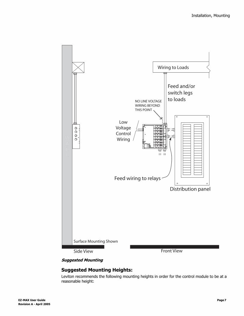
MountingThe cabinets can be mounted only on the surface of the wall. The EZ-MAX Relay Cabinet isnot designed for any flush mounting method.
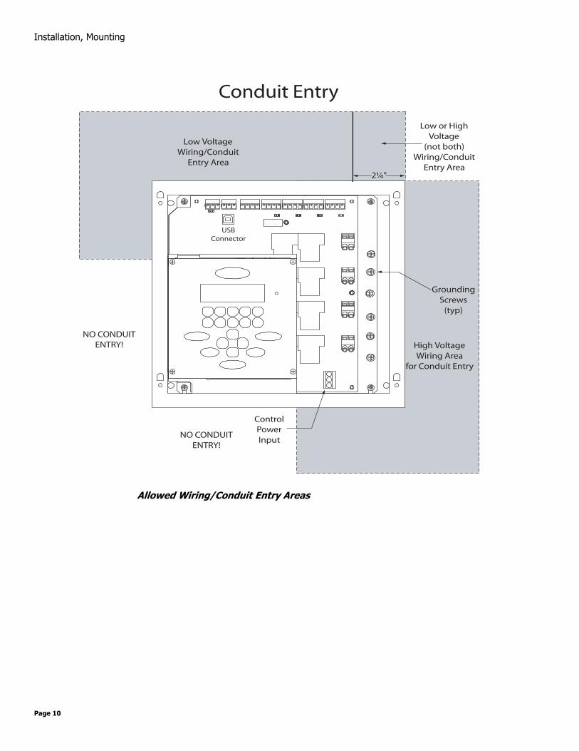
Prior to the consideration of any mounting location, please pay special attention to the allowedlocations for conduit entry.
All cabinets have ample location for conduit entry for feed, loadoutput, and control wiring. Ensure that conduit entry is only inthe allowed locations. Refer to the above figures in theproceeding pages for possible locations. Also please ensurethat the power and control electronics are removed prior todrilling or punching holes for conduit entry.
1 A 2 A G
S L OW BL O W F US E
GroundingScrews
(typ)
ControlPowerInput
2¼"
Low or HighVoltage
(not both)Wiring/Conduit
Entry Area
Low VoltageWiring/Conduit
Entry Area
High VoltageWiring Area
for Conduit Entry
USBConnector
NO CONDUITENTRY!
NO CONDUITENTRY!
e 6
Installation, Mounting
Suggested Mounting
Suggested Mounting Heights:Leviton recommends the following mounting heights in order for the control module to be at areasonable height:
Front View
Feed and/orswitch legs to loads
Feed wiring to relays
WALL
Side View
Distribution panel
Surface Mounting Shown
Wiring to Loads
LowVoltageControlWiring
NO LINE VOLTAGEWIRING BEYONDTHIS POINT
EZ-MAX User Guide Page 7 Revision A - April 2005

Installation, Mounting
Location of cabinets• Cabinets generate heat (see table below). Make sure they are mounted in a conditioned
space where the temperature will be 0-40o C (32-104oF)• Reinforce the wall for strength as required for weight and local code• Clearance on left and right side of the panel should be maintained at 1 1/2 " or greater• Relays will click while in operation. Please locate the panels where audible noise is
acceptable.
Mounting CabinetStep 1: Locate where the cabinet will be hung on the wall. Choose a location in a dry area
that is convenient to the branch circuit panel. Step 2: Leviton recommends that cabinet mounting hardware reach through the drywall
and attaches to wall studs or other suitable solid backing. However, properly sized struts and suitable drywall hardware can also be used. They must distribute the load to the anchors without exceeding the recommended anchor limit. Using drywall screws directly through drywall without a stud is not recommended. Make sure that there is adequate support
Step 3: Loosen the (4) cover screws and remove the cover by sliding the cover up and off. Appropriately store the cover for future use.
Step 4: Locate the mounting plate assembly attached to the back wall of the enclosure. Locate the 4 mounting screws in the 4 corners of the rear plate. Loosen these 4 screws. Lift the entire electrical assembly up and out of the enclosure. Do not attempt to remove the keyboard separately from its mounting bracket. Store the assembly in a protected, clean, dry place. Tighten the 4 screws so they don't get lost.
Step 5: Prior to proceeding, reference the figures below which show the location of the mounting holes and allowed conduit entry locations.
Step 6: Orient the enclosure so that the "UP" arrow on the label inside the enclosure is pointing up. Note that the high-voltage conduit access is through the right end of the bottom, the right side and the right end of the top. Note that the low-voltage (Class 2) conduit access is through the top end of the left side and the left end of the top. Cut or punch the desired conduit openings. Do not cut openings in the back of the enclosure or the bottom end of the left side or the left end of the bottom as it will no longer be possible to re-install the electrical assembly.
Step 7: Mount to a substantial indoor vertical surface with hardware supplied by others through the 4 - 0.24 holes in the back wall for #10 hardware. The enclosure is Type 1 for indoor use only
Cabinet Suggested Mounting height to bottom of cabinet
4 Relay Panel 62" (157 cm)
Cabinet MAX BTU/HR
4 Relay Cabinet 97
Page 8
Installation, Mounting
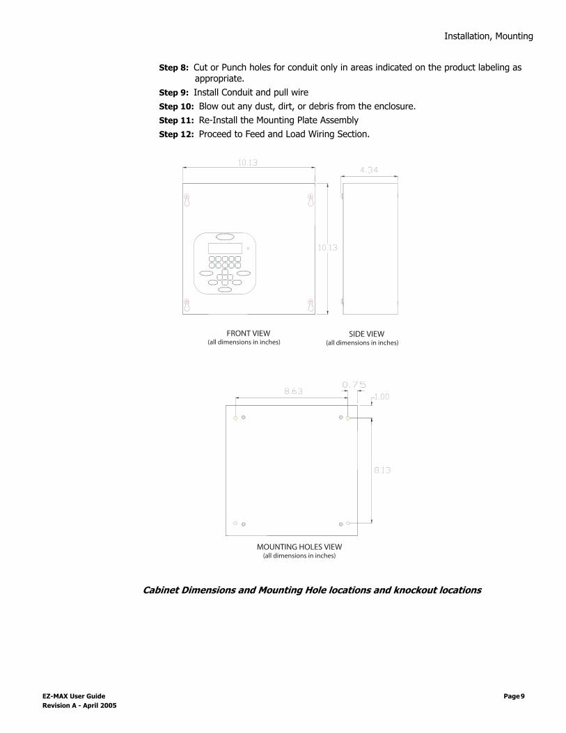
Step 8: Cut or Punch holes for conduit only in areas indicated on the product labeling as appropriate.
Step 9: Install Conduit and pull wireStep 10: Blow out any dust, dirt, or debris from the enclosure.Step 11: Re-Install the Mounting Plate AssemblyStep 12: Proceed to Feed and Load Wiring Section.
Cabinet Dimensions and Mounting Hole locations and knockout locations
FRONT VIEW(all dimensions in inches)
SIDE VIEW(all dimensions in inches)
MOUNTING HOLES VIEW(all dimensions in inches)
10.13
10.134.34
8.63
8.13
1.000.75
EZ-MAX User Guide Page 9 Revision A - April 2005
Installation, Mounting
Allowed Wiring/Conduit Entry Areas
1 A 2 A G
S L OW BL O W F US E
Conduit Entry
GroundingScrews
(typ)
ControlPowerInput
2¼"
Low or HighVoltage
(not both)Wiring/Conduit
Entry Area
Low VoltageWiring/Conduit
Entry Area
High VoltageWiring Area
for Conduit Entry
USBConnector
NO CONDUITENTRY!
NO CONDUITENTRY!
Page 10

Feed and Load Wiring, Overview of Power Wiring -
Feed and Load Wiring
Overview of Power Wiring - Feed\Line WiringWiring is simple. All you need is the following:• Dedicated circuit for control power - Hot, Neutral and Ground• Individual feeds from branch circuit breakers, input circuits• Individual load wires leaving relays, output circuits.
Since the panel is fed from multiple circuits, locate each one and lock-out each feed in the OFF position.
All cabinets have ample location for conduit entry for feed, load output, and control wiring.Ensure that conduit entry is only in the allowed locations. Refer to the above figures in theproceeding pages for possible locations. Also please ensure that the power and controlelectronics are removed prior to drilling or punching holes for conduit entry.
EZ-MAX User Guide Page 11 Revision A - April 2005

Feed and Load Wiring, Overview of Power Wiring - Feed\Line Wiring
Cabinet Connections & Orientation
1 A 2 A G
S L OW BL O W F US E
RelayInput &Outputs
Relay #1
Relay #2
Relay #3
Relay #4
(Typical ofall relays)
USBConnector
ControlPowerInput
Dedicated Photocelland OccupancySensor Inputs
DedicatedCommon
& Switch Inputs
Page 12

Feed and Load Wiring, Control Electronics Power Wiring
Control Electronics Power Wiring Your relay cabinet requires specific power circuit for the control electronics. Levitonrecommends that this power circuit be dedicated specifically and used only for power to thecontrol electronics.
If the control electronics must function during a power outage or other interruption, the control electronics power must be fed from a UPS, generator, or other guaranteed source.
To connect your relay cabinet’s control electronics to power, please follow the following steps:Step 1: Connect the relay cabinet to the circuit breaker panel using conduit.Step 2: Remove all cuttings and dirt.Step 3: Run a dedicated circuit from the circuit panel or distribution panel to the relay
panel for the control electronics. Make sure the power is off at the breaker.Step 4: Wire the circuit as shown in the following figure:
Step 5: Connect the circuits ground wire to the relay cabinetStep 6: Keep the circuit off until all wires are landed in the cabinet.
Line and Load Circuit WiringYour relay cabinet has multiple relay circuits of a specific type depending on your relay cabinetmodel. For specifications of the different relay types, please reference the chart below.
Testing the CircuitsPrior to connecting any circuit to a relay, and after all load and feed connections have beenmade opposite the relay cabinet, test the circuit by following this procedure:
Step 1: Turn off the breaker feeding the circuitStep 2: Ensure that all connections and wiring between the relay cabinet and the circuit
breaker panel are complete
ControlPowerInput
277VAC (347V on 347V models)120VAC Neutral
13W RequiredControl Input Power
EZ-MAX User Guide Page 13 Revision A - April 2005

Feed and Load Wiring, Line and Load Circuit Wiring
Step 3: Ensure that all connections and wiring between the relay cabinet and the load are complete
Step 4: At the relay cabinet, connect the feed(s) for relay #1 to the load for relay #1 with a wire nut or other appropriate means.
Step 5: Energize the circuit by turning on the circuit breaker.Step 6: Resolve any mis-wiring, shorts, etc. for the connected circuitStep 7: Repeat the above steps for all circuits in this relay panel. When all circuits have
been tested, disconnect all Line’s from Loads and proceed to the next section.
Wiring the relaysStep 1: Connect the line (feed/circuit breaker) side of the circuit to the "input" terminal(s)
on the relay card.Step 2: Connect the load side of the circuit to the "output" terminal(s) on the relay card.Step 3: Please note that relay card terminals accept the following wire sizes:
Wire Sizes for Relays
Wire the relay cards by following the wiring diagrams.
Model Relay Wire Size Wire Type Torque
re4bd-104 Z-MAX(Standard, 1-Pole) 20-8 AWG Copper Solid or Stranded 7 in-lbs
re4bd-204 2-Pole 20-6 AWG Copper Solid or Stranded 20.5 in-lbs
re4bd-C04 347V 20-6 AWG Copper Solid or Stranded 20.5 in-lbs
Page 14

Feed and Load Wiring, Line and Load Circuit Wiring
Wiring Diagram for EZ-MAX Standard 1-Pole Relay (re4bd-104)
1 A 2 A G
S L OW BL O W F US E
Relay #1
Relay #2
Relay #3
Relay #4
Load
Line (fromDistributionPanel)
(Typical ofall relays)
USBConnector
EZ-MAX User Guide Page 15 Revision A - April 2005

Feed and Load Wiring, Line and Load Circuit Wiring
Wiring Diagram for 2-Pole Relay Card (re4bd-204)
Wiring Diagram for 347V Canadaian Relay (re4bd-C04)
Load (Pole 1 & 2)
Line (Poles 1 & 2)(from Dist. Panel)
Wiring Typical forall relays
WARNING: Miswiring of relaysmay result in product damage
or personal injury.
Load (Pole 1 & 2)
Line (Poles 1 & 2)(from Dist. Panel)
Wiring Typical forall relays
WARNING: Miswiring of relaysmay result in product damage
or personal injury.
N/C
N/C
Page 16
Feed and Load Wiring, Line and Load Circuit Wiring
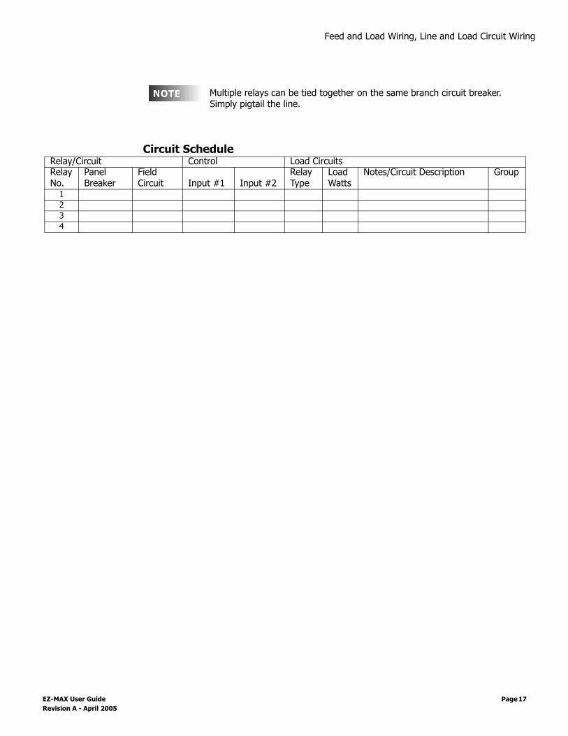
Multiple relays can be tied together on the same branch circuit breaker. Simply pigtail the line.
Circuit ScheduleRelay/Circuit Control Load CircuitsRelay No.
Panel Breaker
Field Circuit Input #1 Input #2
Relay Type
Load Watts
Notes/Circuit Description Group
1234
EZ-MAX User Guide Page 17 Revision A - April 2005

Feed and Load Wiring, Line and Load Circuit Wiring
Page 18

Low Voltage Control Wiring, Control Input Wiring
Low Voltage Control Wiring
Control Input WiringOnce the power wiring has been completed, control wiring can be addressed. Terminate allcontrol wiring directly to the terminal blocks on the printed circuit board. Use a small 1/8-in.flat screwdriver on these terminals
Control Wire Type and Size
The digital control panel can accept the following control signals:• Low Voltage inputs (Switches)• Photocells• Occupancy Sensors• Dry Contacts• Analog 0-10VDC Inputs
All Control wiring is Class 2!
Configuring Low Voltage InputsFor each input there are (3) things which you must consider:
1 What will be connected to the input,2 Will it supply voltage to trigger an "on" or provide a connection to common to signal
an "on",3 What are the power requirements for this input --> what are the power requirements
for all inputs
Low Voltage Input ConnectionsYour EZ-MAX relay cabinet has a total of (6) inputs which can be configured as follows:• Inputs #1-4 can have any of the following functions
• Low Voltage Switch• Occupancy Sensor• Photocell, Switched (on or off, trigger point set at photocell)
Connector Type Wire Size and type Torque
Switch Inputs 14-24 AWG, Stranded 2 in-lb.
Terminal blocks are 2-part terminals and can be removed forease of termination. When reinstalling them make sure theyare plugged in the correct direction for the way they werewired.
EZ-MAX User Guide Page 19 Revision A - April 2005

Low Voltage Control Wiring, Control Input Wiring
• Photocell, 0-10V, 0-10V returned proportional to the amount of light received by the photocell. Trigger point(s) set at relay cabinet.
• Contact Closure• Input #5, Dedicated Occupancy Sensor• Input #6, Dedicated Photocell, either -Switched or 0-10V
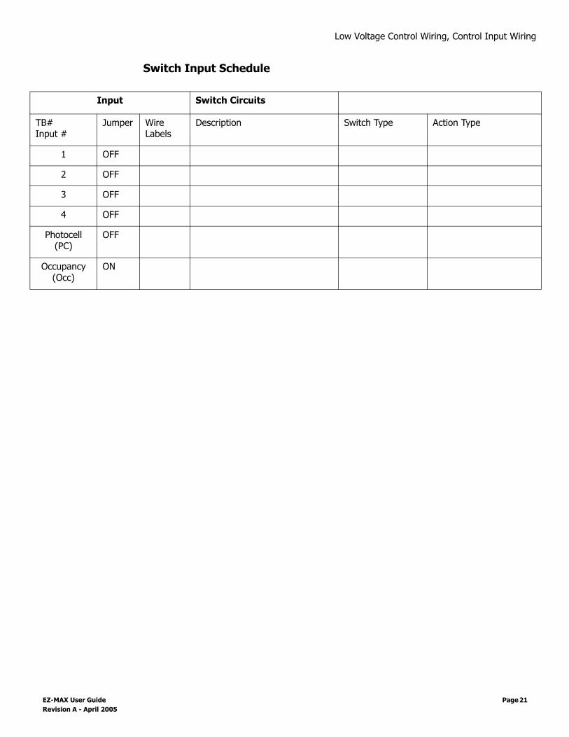
Each input type is discussed in detail in the following pages. For now, please just find ithelpful to identify what will be connected to each input. That will in turn tell you how to wirethe input and make any necessary hardware and later on software configurations. There is aswitch input schedule as part of this chapter which gives you a location to document yourconnections.
Input TriggerEach of the low voltage inputs can be triggered by either voltage or a connection to common.When supply voltage to the input to trigger, we call this "pulling up the input" or also "activehigh." When a connection to common triggers the input, we call this "pulling down the input"or also "active low."
As shipped from the factory, all inputs are expecting to be active high, that is receiving voltageto trigger. Active High inputs must not exceed a nominal 24VDC. To change this from anactive high input to an active low input, the polarity jumper must change position. Pleasereference the illustrations in this chapter for the location and settings of this jumper.
Input Power RequirementsYour relay cabinet has a finite amount of power which it can supply to all inputs andconnected devices. This topic is discussed in detail in the following section titled "PowerRequirements" Please make sure that you do not exceed the amount of available power ordamage to your relay cabinet or connected devices may occur.
Page 20
Low Voltage Control Wiring, Control Input Wiring
Switch Input Schedule
Input Switch Circuits
TB#Input #
Jumper Wire Labels
Description Switch Type Action Type
1 OFF
2 OFF
3 OFF
4 OFF
Photocell (PC)
OFF
Occupancy(Occ)
ON
EZ-MAX User Guide Page 21 Revision A - April 2005

Low Voltage Control Wiring, Control Input Wiring
Low Voltage Input Terminals & Connections
Each of the low voltage inputs has different wiring requirements. However, this section isdesigned to give you a brief introduction to the inputs and sections later in this manual givedetail as to the specific wiring based on each connection type.
Each Input has a four position screw terminal. The terminal can be pulled off its base for ease of wiring. The pin assignments are shown in the figure above. The terminal labeled LED Outis used to drive an LED or pilot lamp on the switch or other annunciating device if one isavailable. This output is reated at 24Vdc and xmA maximum.
1 A 2 A G
S L OW BL O W F US E
Relay #1
Relay #2
Relay #3
Relay #4
USBConnector
ControlPowerInput
AdditionalCommon
Terminations
RJ Connectorfor Modem
277VAC (347V on 347V models)120VAC Neutral
Socket forOptional Modem
PhotocellIN +V COM
OccupancySensor
IN +24V COM
Input #1(2-4 typical)
ON OFF +24V OUT
INPUT 1INPUT 2INPUT 3INPUT 4
13W RequiredControl Input Power
Page 22

Low Voltage Control Wiring, Control Input Wiring
Each input has an associated 2 pin polarity header. This header is shipped from the factoryun-jumpered. Please reference the illustrations in this section for the appropriateconfiguration of this jumper. Generally, if you are supplying voltage to trigger the input, thejumper should remain in it’s default state, OFF.
General Requirements for connecting device to Low Voltage InputsStep 1: Connect leads per wiring diagram as illustrated in the figure below.
Step 2: Twist strands of each lead tightly (making sure that there are no stray strands) and push firmly into appropriate plug connector location.
Step 3: Tighten the screws on the plug connector—making sure that no bare conductor is showing.
Step 4: Plug the connector back onto the control module with the screws facing the front and the wires coming out of the connector towards the top of the cabinet.
EZ-MAX User Guide Page 23 Revision A - April 2005

Low Voltage Control Wiring, Control Input Wiring
Page 24

,
Connecting Low Voltage SwitchesYour EZ-MAX relay panels has (4) inputs which can be used to connect low voltage inputs.
Leviton recommends using 18 gauge wire for the low voltage connections.
Each Input has a four position screwterminal. The terminal can be pulledoff its base for ease of wiring. The pinassignments are shown in the figureto the right. The terminal labeled LEDOutput is used to drive an LED or pilotlamp on the switch, or otherannunciator panel as may beavailable. The output is active lowwith an open collector output. It iscapable of sinking up to 0.04 amps.
Both Maintained and Momentary typeswitches can be used. Although theyare wired the same, the input has to be configured accordingly for the switches to work asexpected (See Define Switch Types within the Configuration section). The figure belowillustrates wiring for both switch types and both polarity settings.
When using Leviton Low Voltage Switches, use the factory default, polarity jump off and +24 volt connection.
Step 1: Connect leads per the diagram above and as follows:• ON = Output from Switch, indicates when to turn lights on/off if in momentary
operation, or ON when switch pressed, OFF when switch released in a maintained operation, or ON if in Momentary On/Off mode. (ON & OFF inputs must be used for this mode. This is the mode used when using a GE style switch.
• OFF = Output from Off switch when in Momentary On/Off Mode• +24V = +24V DC power to device• LED = LED on device or other annuciator
Step 2: Twist strands of each lead tightly (making sure that there are no stray strands) and push firmly into appropriate plug connector location.
Step 3: Tighten the screws on the plug connector—making sure that no bare conductor is showing.
Step 4: Plug the connector back onto the control module with the screws facing the front and the wires coming out of the connector towards the top of the cabinet.
1 A 2 A G
S L OW BL O W F US E
USB
Input #1(2-4 typical)
ON OFF +24V OUT
INPUT 1INPUT 2INPUT 3INPUT 4
COMMON
EZ-MAX User Guide Page 25 Revision A - April 2005

,
Page 26

,
Occupancy SensorsYour EX-MAX relay cabinet has (1) dedicated Occupancy Sensor input. This should be the firstplace you connect an Occupancy Sensor. If more sensors are required for your project, theymay be connected to any of the other (4) switch inputs. Wiring for both styles of input issimilar, however, the switch inputs #1-#4 do not have a common terminal so you must usethe common terminal block for common connections.
Step 1: Connect leads per wiring diagram below.
Occupancy Sensor Termination using Dedicated Occ Sensor Terminal
Step 2: Twist strands of each lead tightly (making sure that there are no stray strands) and push firmly into appropriate plug connector location.
Step 3: Tighten the screws on the plug connector—making sure that no bare conductor is showing.
Step 4: Plug the connector back onto the control module with the screws facing the front and the wires coming out of the connector towards the top of the cabinet.
1 A 2 A G
S L OW BL O W F US E
IN +24V COM
INPUT 1INPUT 2INPUT 3INPUT 4
OccupancySensor
(Input #6)
Black
Red
Blue
EZ-MAX User Guide Page 27 Revision A - April 2005

,
Page 28

,
PhotocellsYour EX-MAX cabinet is capable of supporting the following types of photocells:• Switched Photocell (On/Off, trigger point set at photocell) connected to the dedicated
photocell input• 0-10V Photocell, connected to the dedicated photocell input• Switch Photocell connected to one of the switch inputs• 0-10V Photocell connected to one of the switch inputs
If you’re using a photocell, you should have it connected to the dedicated input first prior toconnecting it to any of the other inputs.
Step 1: Connect leads per wiring diagram as illustrated in one of the figures below:
0-10VDC Photocell
1 A 2 A G
S L OW BL O W F US E
USBConnector
IN +V COM
INPUINPUT 4
Common
(DC Ground)
Power (+24VDC)
Control Signal
(+0-10VDC)
PhotoCell
Jumper Off For 0-10VDCPhotocell
EZ-MAX User Guide Page 29 Revision A - April 2005

,
Switching Photocell
Step 2: Twist strands of each lead tightly (making sure that there are no stray strands) and push firmly into appropriate plug connector location.
Step 3: Tighten the screws on the plug connector—making sure that no bare conductor is showing.
Step 4: Plug the connector back onto the control module with the screws facing the front and the wires coming out of the connector towards the top of the cabinet.
Step 5: If using a switched photocell, make sure that the jumper below the connector is in the "ON" position.
1 A 2 A G
S L OW BL O W F US E
USBConnector
IN +V COM
INPUT 1INPUT 2INPUT 3INPUT 4
Switch LegPhotoCell
Jumper ON For switchingPhotocell
Switch Leg
AC Power
Note: Switch Legs must be completly isolated from Photocell AC power and should be connected to either side of the switching relay at the photocell.
Note: If your switching photo-cell requires +24VDC power, this power can be sourced from the cabinet just like a 0-10VDC photocell. The switch legs should still be between COM & IN terminals
Page 30

,
Wiring with an External Power SupplyWhen needed, an external class 2 power supply can be used to supply power to Low Voltagedevices connected to the low voltage inputs. When this is required, wire the system byfollowing the diagram below.
Using an External Power Supply
You must consider the following when using an external power supply:• Use the external supply for +24V (or other required device) and common to the devices• Any return from a device which is connected to a switch input must not exceed +24VDC.• Connect the common from the external supply to the common of any switch input• Use the device output (Control Signal) to the "IN" terminal of the respective switch input• Use the "OUT" terminal from the switch input for device feedback, like a low voltage switch
LED• DO NOT connect the +V of the external supply to any of the +24V terminals of teh relay
panle. This will nullify the Class 2 rating of the power supplies.
IN
OFF
+24
OUT
IN
OFF
+24
OUT
External
Power
Supply
+24VDC typ.
Device
Device
Power +V
Common
Optional LED
Optional LED
Control Signal
+24VDC or 0-10VDC
Depends on Device
Control Signal
+24VDC or 0-10VDC
Depends on Device
COM
COM
COM
COM
Cabinet
Common
Terminals
EZ-MAX User Guide Page 31 Revision A - April 2005

,
Page 32
, Power Considerations for Control Systems
Power Considerations for Control SystemsThe control system should be carefully planned out to take into consideration these importantissues:• Power Supply for connected devices• Wire Size for Power Runs
On systems where full factory drawings have been provided, our Applications Engineeringdepartment has already managed these calculations for you so you need only follow theinstructions on the system drawing. However, on any installation where factory drawings werenot provided, the information contained within this chapter must be followed to ensure that allof your devices operate properly and without over-current failures or complete inoperatbility.
The contents of this chapter contains information which applies to many Leviton products and is not necessarily limited in scope to just the product which included this manual. As such, there may be information in this chapter which is not relevant to your particular installation. Please overlook this. If you have questions about ANY information contained herein, please immediately contact our Technical Services Department prior to proceeding with installation.
TerminologyPlease review these definitions which are used throughout this chapter:• Power Supply or Supply - references a device which supplies power to other devices• Power Control Device (PCD) - refers to a device which controls power. Examples of Devices
in our product line which control power our dimming racks, relay panels, A-2000, i-series e, Z-MAX, etc. Generally PCD’s also supply a certain amount of power to connected low voltage control devices
• Control Devices or Low Voltage Control Devices or Device - these terms all refer to a control devices which is connected to a Power Control Device (PCD.) These devices could be simple low voltage switches, Occupancy Sensors, or D8000 control stations.
• Luma-Net - is one of our network lighting control protocols. Luma-Net is an RS-485 based control protocol used by D8000 & D4200 control devices. Many of our PCD (Power Control Device) products have a direct data connection for a Luma-Net device. All Luma-Net Control Devices require power in one form or another. This power generally accompanies the data wires.
• Unit Load - (1) Unit load is defined as 25mA, or 0.025A. It is an arbitrary definition defined by Leviton and was created to simplify power calculations.
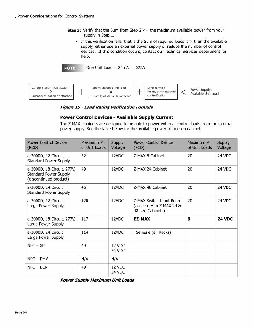
Power Requirements & Maximum Run LengthEach Control Device used in your system has a different load (draw) and each PCD’s cansupport a different total load (supply.) The steps although at times involved for determiningthe total load of your network and verifying that the supply is sufficient are quite simple--or atleast logical:
Step 1: Determine the maximum supply current of your supply, be it a PCD or other Power Supply. Convert this available to Unit Loads if necessary.
Step 2: Sum the required load of each Control Device, expressed in unit loads
EZ-MAX User Guide Page 33 Revision A - April 2005
, Power Considerations for Control Systems
Step 3: Verify that the Sum from Step 2 <= the maximum available power from your supply in Step 1.
• If this verification fails, that is the Sum of required loads is > than the available supply, either use an external power supply or reduce the number of control devices. If this condition occurs, contact our Technical Services department for help.
One Unit Load = 25mA = .025A
Figure 15 - Load Rating Verification Formula
Power Control Devices - Available Supply CurrentThe Z-MAX cabinets are designed to be able to power external control loads from the internalpower supply. See the table below for the available power from each cabinet.
Power Supply Maximum Unit Loads
Power Control Device (PCD)
Maximum # of Unit Loads
Supply Voltage
Power Control Device (PCD)
Maximum # of Unit Loads
Supply Voltage
a-2000D, 12 Circuit,Standard Power Supply
52 12VDC Z-MAX 8 Cabinet 20 24 VDC
a-2000D, 18 Circuit, 277V,Standard Power Supply(discontinued product)
49 12VDC Z-MAX 24 Cabinet 20 24 VDC
a-2000D, 24 CircuitStandard Power Supply
46 12VDC Z-MAX 48 Cabinet 20 24 VDC
a-2000D, 12 Circuit,Large Power Supply
120 12VDC Z-MAX Switch Input Board (accessory to Z-MAX 24 & 48 size Cabinets)
20 24 VDC
a-2000D, 18 Circuit, 277V,Large Power Supply
117 12VDC EZ-MAX 6 24 VDC
a-2000D, 24 CircuitLarge Power Supply
114 12VDC i Series e (all Racks)
NPC – XP 49 12 VDC24 VDC
NPC – DHV N/A N/A
NPC – DLR 49 12 VDC24 VDC
Control Station A Unit Load
XQuantity of Station A's attached
+Same formulafor any other attached control Station
Control Station B Unit Load
XQuantity of Station B's attached
<+ Power Supply's Available Unit Load
Page 34

, Power Considerations for Control Systems
The sum of all devices connected to all power output terminals can not exceed the Maximum number of Unit Loads for your cabinet.
Control Device Loads
Control Devices Unit Load @ 12VDC
Unit Load @ 24VDC
Station Type Unit Load @ 12VDC
Unit Load @ 24VDC
D4200 LCD 5 2 Z-MAX Digital Switch, 1 Button N/A 0.6
D4200 Entry (Button), 2 1 Z-MAX Digital Switch, 2 Buttons N/A 0.8
D4200 Room Combine Station 3 1 Z-MAX Digital Switch, 3 Buttons N/A 1.0
D4200 Remote I/R 2 1 Z-MAX Digital Switch, 4 Buttons N/A 1.1
Luma-Net Hub 6 3 Z-MAX Digital Switch, 5 Button N/A 1.3
D8000 LCD 3 2 Z-MAX Digital Switch, 6 Button N/A 1.0
D8000 Entry (Button) 2 1 Z-MAX Digital Switch, 8 Button N/A 1.1
D8000 Slider 2 1 Z-MAX Digital Switch, 10 Button N/A 1.3
D8000 Key switch 1 1 1 Button Low Voltage Switch 0.6
D8000 Port (LumaEdit, A/V, etc.)
2 1 2 Button Low Voltage Switch 0.9
D8000 Combine/Closure (Advanced)
11 10 3 Button Low Voltage Switch 1.2
Infrared Only Occupancy Sensor
N/A 1.2 4 Button Low Voltage Switch 1.5
Ultrasonic Only Occupancy Sensor
N/A 1.2 5 Button Low Voltage Switch 1.8
Multi-tech Occupancy Sensor N/A 1.2 6 Button Low Voltage Switch 2.1
Ultrasonic 2-Way Occupancy Sensor
N/A 1.4 8 Button Low Voltage Switch 2.7
Multi-tech 2-Way Occupancy Sensor
N/A 1.4 10 Button Low Voltage Switch 3.3
Photocell, odc0p-00w Photocell, pcatr-000
Photocell, pcind-000 -
Photocell, pcout-000 -
Photocell, pcsky-000 -
EZ-MAX User Guide Page 35 Revision A - April 2005

, Power Considerations for Control Systems
Power Wire - Run LengthThe maximum total run length of each segment is a function of the total number of unit loads.A run becomes to long when the voltage drop, due to wire size and run length, increase to apoint where the station does not have sufficient voltage to operate. The maximum run length,in feet, based on the total number of unit loads is shown below:
(2) Tables are provided, (1) @ 12VDC and (1) at 24VDC. Make sure that you use the correct table!
Wire Size vs. Length of Runs - Power Wiring @12 VDC
14 AWG (Feet) 12 AWG (Feet) 10 AWG (Feet)
10 Unit Loads 1905 3000 4800
20 Unit Loads 950 1500 2400
30 Unit Loads 630 1000 1600
40 Unit Loads 475 750 1200
50 Unit Loads 380 600 960
60 Unit Loads 315 500 800
70 Unit Loads 270 425 685
80 Unit Loads 235 375 600
90 Unit Loads 210 330 530
100 Unit Loads 190 300 480
110 Unit Loads 170 270 435
120 Unit Loads 155 250 400
Page 36
, Modem Installation/Phone Line Connection
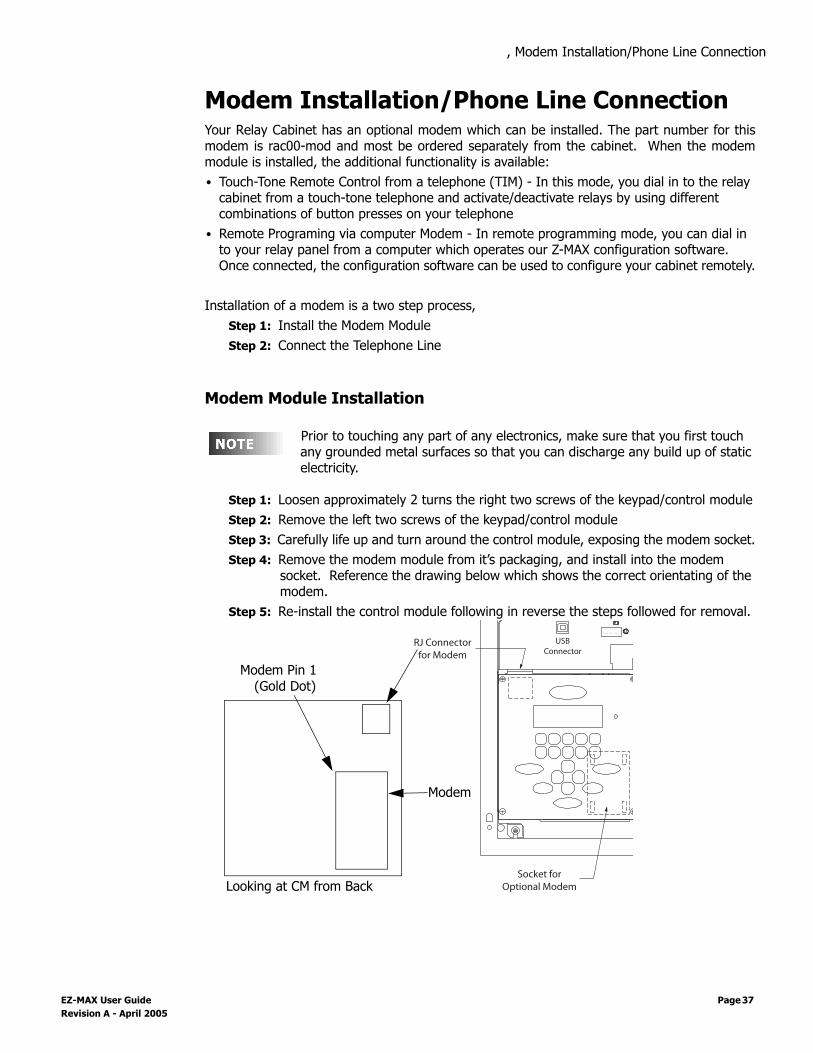
Modem Installation/Phone Line ConnectionYour Relay Cabinet has an optional modem which can be installed. The part number for thismodem is rac00-mod and most be ordered separately from the cabinet. When the modemmodule is installed, the additional functionality is available:• Touch-Tone Remote Control from a telephone (TIM) - In this mode, you dial in to the relay
cabinet from a touch-tone telephone and activate/deactivate relays by using different combinations of button presses on your telephone
• Remote Programing via computer Modem - In remote programming mode, you can dial in to your relay panel from a computer which operates our Z-MAX configuration software. Once connected, the configuration software can be used to configure your cabinet remotely.
Installation of a modem is a two step process, Step 1: Install the Modem ModuleStep 2: Connect the Telephone Line
Modem Module Installation
Prior to touching any part of any electronics, make sure that you first touch any grounded metal surfaces so that you can discharge any build up of static electricity.
Step 1: Loosen approximately 2 turns the right two screws of the keypad/control moduleStep 2: Remove the left two screws of the keypad/control moduleStep 3: Carefully life up and turn around the control module, exposing the modem socket.Step 4: Remove the modem module from it’s packaging, and install into the modem
socket. Reference the drawing below which shows the correct orientating of the modem.
Step 5: Re-install the control module following in reverse the steps followed for removal.1 A 2 A G
S L OW BL O W F US E
USBConnector
RJ Connectorfor Modem
Socket forOptional ModemLooking at CM from Back
Modem
Modem Pin 1(Gold Dot)
EZ-MAX User Guide Page 37 Revision A - April 2005

, Modem Installation/Phone Line Connection
Page 38
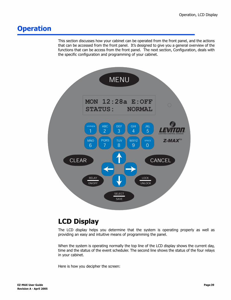
Operation, LCD Display
Operation
This section discusses how your cabinet can be operated from the front panel, and the actionsthat can be accessed from the front panel. It’s designed to give you a general overview of thefunctions that can be access from the front panel. The next section, Configuration, deals withthe specific configuration and programming of your cabinet.
LCD DisplayThe LCD display helps you determine that the system is operating properly as well asproviding an easy and intuitive means of programming the panel. When the system is operating normally the top line of the LCD display shows the current day,time and the status of the event scheduler. The second line shows the status of the four relaysin your cabinet.
Here is how you decipher the screen:
CANCELCLEAR
UNLOCKON/OFF
RELAY LOCK
SELECT
SAVE
MNO PQRS
6 7
HYPHEN
1ABC
2
TUV WXYZ
8 9
DEF
3GHI
4
SPACE
0
JKL
5
MENU
MON 12:28a E:OFF
STATUS: NORMAL
Z-MAXTM
EZ-MAX User Guide Page 39 Revision A - April 2005

Operation, LCD Display
• Day and Time - The clock can display in either 12 or 24 hour mode.• Daylight Savings settings for 12 Hour Clock
• Lower case "a" or "p" indicates that daylight savings is inactive• Uppercase "A" or "P" indicates that daylight savings is active
• Daylight Savings settings for 24 Hour Clock• Lower case "s" indicates that daylight savings is inactive• Lower case "d" indicates that daylight savings is inactive
• Event Scheduler• "E:" will either show
• OFF - Indicating that the event scheduler is turned off• a number indicates the last event that occurred
• Bottom Line - shows the current status of the four relays in your panel. Either On, or Off. An asterik (*) adjacent to any relay indicate that that particular relay is in an override state. The override could be either a timed override or other front panel override.
Programming/Function ButtonsThe several programming buttons are located around the display:• MENU. Allows the user to navigate through the system• SELECT/SAVE. Causes a new readout on the LCD display. • CANCEL: Returns to the previous menu• CLEAR. Clears the text or value that was just entered.• RELAY ON/OFF: Button that allows a user to turn a relay ON or OFF, execute a timed
override, or execute a permanent relay override.• LOCK/UNLOCK: Locks and Unlocks the user interface.
Many parameters can be modified using the LCD screen and a password (setup code), however these modifications should be made by a qualified factory technician.
Navigation ButtonsThe lower center four buttons, used for navigation of menu items, are LEFT , UP ,DOWN , and RIGHT . Generally, the LEFT and RIGHT buttons areused to navigate between ’fields’ on the screen, whereas the UP andDOWN buttons generally change values in the fields.
The keys are used for alpha-numeric data entry.
Arrow Key & Alpha-Numeric Key Functions
5JKL
1-
2ABC
3DEF
4GHI
0SPACE
6MNO
7PQRS
8TUV
9WXYZ
After approximately30 seconds of
inactivity on any menu screen,the LCD will revert back to thestatus screen.
5JKL
1-
2ABC
3DEF
4GHI
0SPACE
6MNO
7PQRS
8TUV
9WXYZ
OR
{FOR FIELD VALUE CHANGES FOR FIELDNAVIGATION
AND
Page 40

Operation, LCD Display
Turning Relays On/Off & Relay Overrides
Pressing the Relay Button enters relay control mode. When i this mode, the following keyscan be used
• Use to adjust the relay number (number keys can also be used)
• Use to adjust the relay state, UP for ON, DOWN for off.
• Pressing (up arrow twice) puts the relay into an override ON state. When in this state, no other relay panel function can alter the state of this relay other than the front panel.
• Pressing (down arrow twice) puts the relay into an override OFF state. When in this state, no other relay panel function can later the state of this relay other than the front panel.
• Pressing Select when in either override on or off mode will allow you to enter a time and then activate Timed Override mode by pressing Select again. A timed override forces the relay into the ON (or off) state for the elapsed period of time. Once the time expires, the relay returns to the function indicated by other controlling devices, or off if none are indicated.
To Turn a Relay On or OffStep 1: Press Relay
Step 2: Use to adjust to the relay number you want to effect. Use to turn the relay off or on
Step 3: Press Menu when complete to return to the main screen, or repeat Step 2
To Override a Relay On or OffStep 1: Press Relay
Step 2: Use to adjust to the relay number you want to effect. Use to override the relay ON, or to override the relay OFF
Step 3: Press Menu when complete to return to the main screen, or repeat Step 2
R L Y : 0 1 O NP R E S S U P F O R
R L Y : 0 1 O V R D E O NP R E S S U P F O R
EZ-MAX User Guide Page 41 Revision A - April 2005

Operation, LCD Display
To Override a Relay On or Off for a specified timeStep 1: Press Relay
Step 2: Use to adjust to the relay number you want to effect. Use to override the relay ON, or to override the relay OFF
Step 3: Press Select to access the override timer
Step 4: Use
Step 5: Pressing 1 5 0 0 would result in the above screen, entering an override time of 15 minutes.
Step 6: Press Select a second time to set and start the timerStep 7: Press Menu to return to the main screen, or repeat steps 2-6.
R L Y : 0 1 O V R D E O NP R E S S U P F O R
R L Y : 0 1 O V R D E O NO V R D T I M E R = 0 0 : 0 0
5JKL
1-
2ABC
3DEF
4GHI
0SPACE
6MNO
7PQRS
8TUV
9WXYZ
R L Y : 0 1 O V R D E O NO V R D T I M E R = 1 5 : 0 0
Page 42

, Determine the Firmware/Software Build
Determine the Firmware/Software BuildKnowing the current version of your the operating software in your cabinet is helpful whencommunicating with the factory about problems with your cabinet or checking against thesoftware version on the website to ensure that you have the latest software.
The Software version is one of the available menu options directly off of the main menu
Step 1: Press the Menu buttonStep 2: Press until the display reads:
Step 3: Press Select/SaveThe display will now show you the version of firmware the unit is running.
How to Decipher the software Build:
Step 4: Pressing in this screen will show you similar screens, indicating similar software/hardware information regarding other components in your relay cabinet. This information may be useful and used by our Technical Services department when diagnosing problems with your relay cabinet
Leviton recommends checking our website www.leviton.comperiodically to ensure that you always have the most currentsoftware your relay cabinet.
M A I N M E N U S E L E C TS O F T W A R E B U I L D
24MHzV1.04/001SM
30JUL041651IDPAS
Luma-Net State (Passive or ID#)
ProcessorSpeed
FirmwareVersion
DatabaseVersion
Cabinet Type
Build Date and Time(not applicable to all models)
EZ-MAX User Guide Page 43 Revision A - April 2005

, Determine the Firmware/Software Build
Page 44

, Factory Defaults
Factory DefaultsIf it ever becomes necessary to restore the factory defaults and begin the programming froma clean slate, simply:
Step 1: Press the Menu ButtonStep 2: Press until you get to the Configuration ScreenStep 3: Press Select/SaveStep 4: Press until you get to the Factory Defaults ScreenStep 5: Press Select /SaveStep 6: Press once and the N will change to a Y.
Step 7: Press Select/Save
FACTORY DEFAULTS
INITIALIZE ? N
Resetting to factory defaults will erase anyprogramming or configuration you’ve completed. Anyparts of this programming you desire to use after therest will have to be recreated from scratchprogramming in your system.
EZ-MAX User Guide Page 45 Revision A - April 2005

, Factory Defaults
Page 46
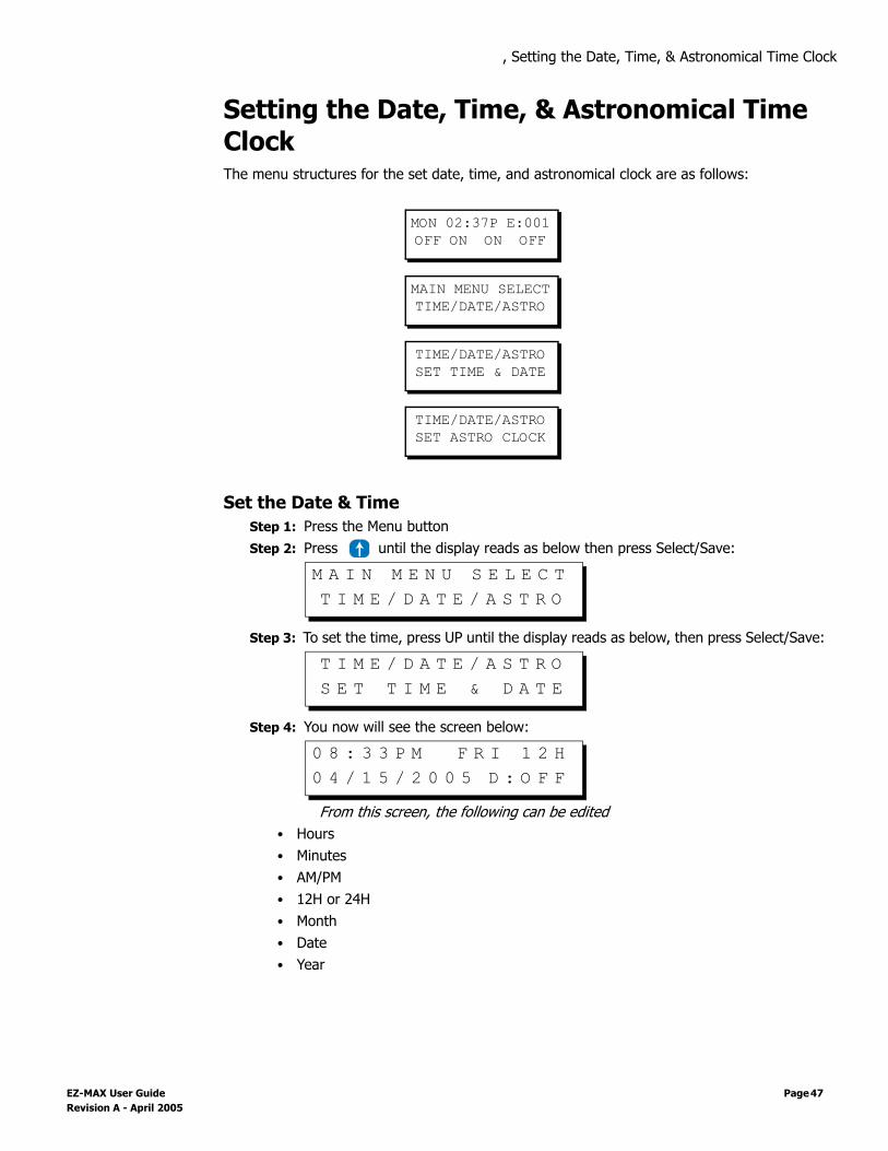
, Setting the Date, Time, & Astronomical Time Clock
Setting the Date, Time, & Astronomical Time ClockThe menu structures for the set date, time, and astronomical clock are as follows:
Set the Date & TimeStep 1: Press the Menu buttonStep 2: Press until the display reads as below then press Select/Save:
Step 3: To set the time, press UP until the display reads as below, then press Select/Save:
Step 4: You now will see the screen below:
From this screen, the following can be edited• Hours• Minutes• AM/PM• 12H or 24H • Month• Date• Year
MON 02:37P E:001OFF ON ON OFF
MAIN MENU SELECTTIME/DATE/ASTRO
TIME/DATE/ASTROSET TIME & DATE
TIME/DATE/ASTROSET ASTRO CLOCK
M A I N M E N U S E L E C TT I M E / D A T E / A S T R O
T I M E / D A T E / A S T R OS E T T I M E & D A T E
0 8 : 3 3 P M F R I 1 2 H0 4 / 1 5 / 2 0 0 5 D : O F F
EZ-MAX User Guide Page 47 Revision A - April 2005

, Setting the Date, Time, & Astronomical Time Clock
• Daylight Saving Time The editable field will be flashing. As always, use the following keys
To the right of the time field, the day of the week is displayed. This field is not editable and is set based on the date setting.
When 12 hour mode is active, the AM/PM field is active for editing. If Daylight Savings Time is active, the field will display in upper case characters. If Daylight Savings Time is inactive, the field will display in lower case characters. If 24 hour mode is active, the AM/PM field is replaced with an “s” or a “d” and is not editable. Instead, the value is determined by the Daylight Savings Time setting. The “s” indicates standard time (Daylight Savings Time inactive); the “d” indicates that Daylight Savings Time is active.
If Daylight Savings time is active, the am/pm will be displayed in Upper class letters.
If you exit from this menu via the MENU or CANCEL button, all changes will be lost.
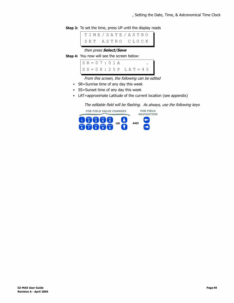
Set the Astronomical Time ClockThe Z-MAX Scheduler allows you to turn lights on or off in relation to sunrise and sunset. Forexample, yard lights can be set to turn on an hour before sunset, and turn off an hour aftersunrise, according to the time of year. The astronomical time clock (Astro Time) calculates the time of sunrise and sunset for everyweek of the year depending on the location of the installation. To use Astro Time you mustknow the approximate latitude (in degrees) (See Appendix A for various cities in NorthAmerica) of the controller’s location, as well as the present time of sunrise and sunset (oftenfound in the daily newspaper). Visit www.srrb.noaa.gov/highlights/sunrise/sunrise.html for acomplete listing of Latitude, Longitude, Sunrise and Sunset information.
Sunrise and Sunset times must be entered as Standard Time. Therefore if you are in the middle of daylight savings time, you must adjust the sunrise and sunset times by 1 hour (2 Hours if European Daylight Savings Time) to bring them back to Standard Time
To set up the astronomical clock:Step 1: Press the Menu buttonStep 2: Press until the display reads
then press Select/Save
5JKL
1-
2ABC
3DEF
4GHI
0SPACE
6MNO
7PQRS
8TUV
9WXYZ
OR
{FOR FIELD VALUE CHANGES FOR FIELDNAVIGATION
AND
M A I N M E N U S E L E C TT I M E / D A T E / A S T R O
Page 48
, Setting the Date, Time, & Astronomical Time Clock
Step 3: To set the time, press UP until the display reads
then press Select/SaveStep 4: You now will see the screen below:
From this screen, the following can be edited• SR=Sunrise time of any day this week• SS=Sunset time of any day this week• LAT=approximate Latitude of the current location (see appendix)
The editable field will be flashing. As always, use the following keys
T I M E / D A T E / A S T R OS E T A S T R O C L O C K
S R = 0 7 : 0 1 A .S S = 0 8 : 2 5 P L A T = 4 5
5JKL
1-
2ABC
3DEF
4GHI
0SPACE
6MNO
7PQRS
8TUV
9WXYZ
OR
{FOR FIELD VALUE CHANGES FOR FIELDNAVIGATION
AND
EZ-MAX User Guide Page 49 Revision A - April 2005

, Setting the Date, Time, & Astronomical Time Clock
Page 50

Configuration the Simple Way, Panel Configuration in Sim-
Configuration the Simple Way
Your relay panel has two modes of configuration, Simple Mode and Advanced Mode. Thedefault configuration mode is called Simple Mode and is designed to be a less complexstreamlined mode for configuring and operating your relay panel. Simple mode differs fromadvanced mode in that many of the advanced features and configuration items have beenremoved from the menu structures. Additionally, all configuration is more question and answerbased allowing for more self-navigation without dependence on the this manual.
The following configurations and configuration changes can be performed when the panel is insimple mode:• Setup the Time Clock Date, Time, and Astronomical Time Clock Settings• Add & Change Scheduled Events• Configure Inputs, Devices connected to inputs, and relays assigned to inputs• Change Configuration ModeAll other configuration options most be defined in Advanced Configuration Mode.
Panel Configuration in Simple ModeConfiguration of your relay panel by simple mode is really a simple process. (pun intended)The steps are as follows:
Step 1: Install your cabinet and terminate all power and control wiringStep 2: Configure your inputsStep 3: Configure any scheduled events
These three steps of course will vary greatly depending upon your particular installation sogeneralized instructions are provided here to help you learn what some of the functionality is.The next few pages will show you how to configure a low voltage switch, a photocell, and thenan occupancy sensor. That will cover step 2. Step 1 has already been covered in priorchapters. Step 3 illustrates the methods used to create and schedule events, or rather relaysturning on or off at a specific time.
Changing Configuration from either simple mode to advancedmode, or from advanced mode to simple mode will never resultin loss of configuration information. This can be used to yourand the end-users advantage by first making all requiredconfiguration settings, then changing the panel configurationmode to Simple Mode. This will allow the user to make basicchanges, but prevent them from making potentially dangerousconfiguration changes.
EZ-MAX User Guide Page 51 Revision A - April 2005
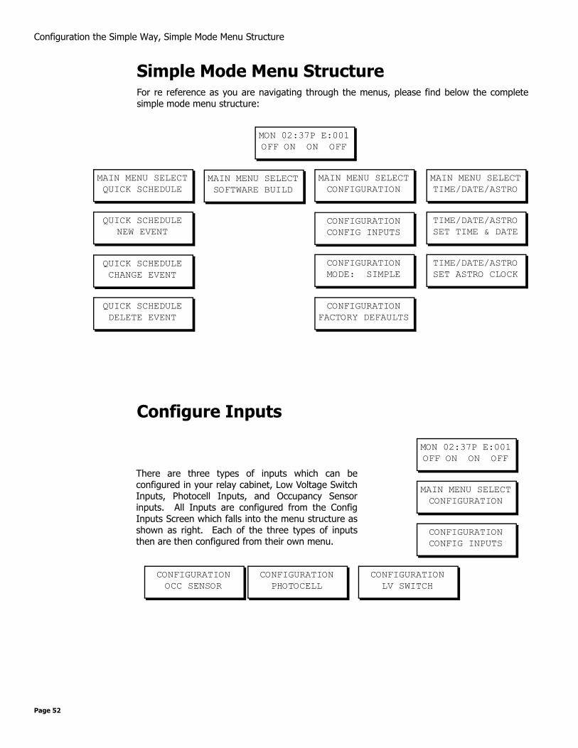
Configuration the Simple Way, Simple Mode Menu Structure
Simple Mode Menu StructureFor re reference as you are navigating through the menus, please find below the completesimple mode menu structure:
Configure Inputs
MON 02:37P E:001OFF ON ON OFF
MAIN MENU SELECTTIME/DATE/ASTRO
CONFIGURATIONCONFIG INPUTS
QUICK SCHEDULENEW EVENT
TIME/DATE/ASTROSET TIME & DATE
MAIN MENU SELECTSOFTWARE BUILD
MAIN MENU SELECTCONFIGURATION
MAIN MENU SELECTQUICK SCHEDULE
TIME/DATE/ASTROSET ASTRO CLOCK
CONFIGURATIONMODE: SIMPLE
CONFIGURATIONFACTORY DEFAULTS
QUICK SCHEDULECHANGE EVENT
QUICK SCHEDULEDELETE EVENT
MON 02:37P E:001OFF ON ON OFF
CONFIGURATIONCONFIG INPUTS
MAIN MENU SELECTCONFIGURATION
CONFIGURATIONLV SWITCH
CONFIGURATIONPHOTOCELL
CONFIGURATIONOCC SENSOR
There are three types of inputs which can beconfigured in your relay cabinet, Low Voltage SwitchInputs, Photocell Inputs, and Occupancy Sensorinputs. All Inputs are configured from the ConfigInputs Screen which falls into the menu structure asshown as right. Each of the three types of inputsthen are then configured from their own menu.
Page 52

Configuration the Simple Way, Configure Inputs
L
ow Voltage Switch Inputs Configuration of this type of input is used when you have some type of switch or othertriggering device connected to one of the inputs from which you desire to turn on or off relays.Several different behaviors are available for configuring of this type of input.
Step 1: From the main menu, navigate to Configuration, Config Inputs, then LV Switch.
Step 2: Enter the input number of the switch input you wish to configure. This is determined by looking at the terminal on your cabinet to witch the switch is conected. After entering the number, press the Select key
Step 3: The relay panel now asks for a behavior:
Your selection for the behavior of your switch will be determined by the type of switch you have and how you desire it to operate. The available behaviors are as follows:
• Momentary - The first press turns on the assigned relays, the second press turns off the assigned relays
• Momentary Timed - Upon the first press, turn on the assigned relays for the specified amount of time. When the time elapses, control of the relays is relinquished to other controls (which generally results in the relays turning off. If the switch is pressed a second time, the timer is reset.
• Maintained - Maintained inputs turn On the relays while the switch is pressed, then turn off the relays when the switch is released
• Preset Off - Turns off all relays in the current preset group. See “Switch/Discrete Inputs” on page 181.
• Preset On - Turns on all relays in the defined preset group. See “Switch/Discrete Inputs” on page 181.
C O N F I G I N P U T SL V S W I T C H
Remember that when navigating menus, pressing Selectalways selects the current menu, and pressing Cancel alwaysnavigates to the previous menu.
E N T E R L V S W I T C HI N P U T N U M B E R : 0 0 2
S E L E C T B E H A V I O RM O M E N T A R Y
To specify the amount of time used for timed inputs, changeconfiguration mode to Advanced, go to System Setting underthe configuration menu, then Global Defaults and change theXXXX value.
EZ-MAX User Guide Page 53 Revision A - April 2005
Configuration the Simple Way, Configure Inputs
• Momentary On/Off - Momentary On/Off is used with switch inputs connected to switches that have separate on & off outputs and in coordination with our switch input adapter cards or switch input adapter kids. These kits provide both the on and off signal on the same switch leg AND require the switch input setting to be defined as Momentary On/Off
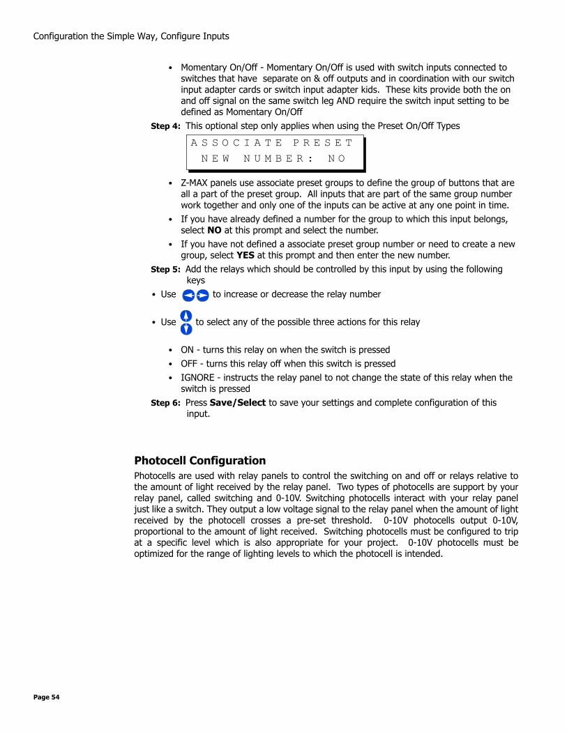
Step 4: This optional step only applies when using the Preset On/Off Types
• Z-MAX panels use associate preset groups to define the group of buttons that are all a part of the preset group. All inputs that are part of the same group number work together and only one of the inputs can be active at any one point in time.
• If you have already defined a number for the group to which this input belongs, select NO at this prompt and select the number.
• If you have not defined a associate preset group number or need to create a new group, select YES at this prompt and then enter the new number.
Step 5: Add the relays which should be controlled by this input by using the following keys
• Use to increase or decrease the relay number
• Use to select any of the possible three actions for this relay
• ON - turns this relay on when the switch is pressed• OFF - turns this relay off when this switch is pressed• IGNORE - instructs the relay panel to not change the state of this relay when the
switch is pressedStep 6: Press Save/Select to save your settings and complete configuration of this
input.
Photocell ConfigurationPhotocells are used with relay panels to control the switching on and off or relays relative tothe amount of light received by the relay panel. Two types of photocells are support by yourrelay panel, called switching and 0-10V. Switching photocells interact with your relay paneljust like a switch. They output a low voltage signal to the relay panel when the amount of lightreceived by the photocell crosses a pre-set threshold. 0-10V photocells output 0-10V,proportional to the amount of light received. Switching photocells must be configured to tripat a specific level which is also appropriate for your project. 0-10V photocells must beoptimized for the range of lighting levels to which the photocell is intended.
A S S O C I A T E P R E S E TN E W N U M B E R : N O
Page 54
Configuration the Simple Way, Configure Inputs
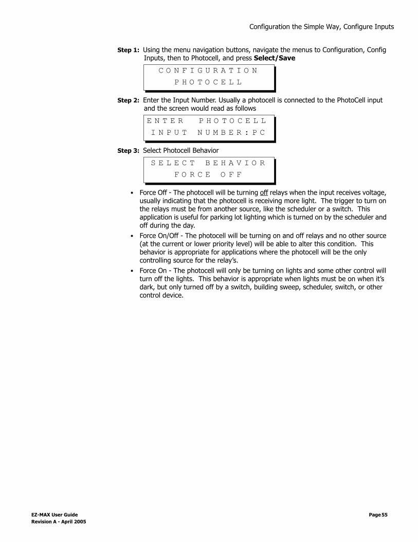
Step 1: Using the menu navigation buttons, navigate the menus to Configuration, Config Inputs, then to Photocell, and press Select/Save
Step 2: Enter the Input Number. Usually a photocell is connected to the PhotoCell input and the screen would read as follows
Step 3: Select Photocell Behavior
• Force Off - The photocell will be turning off relays when the input receives voltage, usually indicating that the photocell is receiving more light. The trigger to turn on the relays must be from another source, like the scheduler or a switch. This application is useful for parking lot lighting which is turned on by the scheduler and off during the day.
• Force On/Off - The photocell will be turning on and off relays and no other source (at the current or lower priority level) will be able to alter this condition. This behavior is appropriate for applications where the photocell will be the only controlling source for the relay’s.
• Force On - The photocell will only be turning on lights and some other control will turn off the lights. This behavior is appropriate when lights must be on when it’s dark, but only turned off by a switch, building sweep, scheduler, switch, or other control device.
C O N F I G U R A T I O NP H O T O C E L L
E N T E R P H O T O C E L LI N P U T N U M B E R : P C
S E L E C T B E H A V I O RF O R C E O F F
EZ-MAX User Guide Page 55 Revision A - April 2005

Configuration the Simple Way, Configure Inputs
olled
the
three
ding ates not e
youron of
Step 4: Enter the delay time. This is the time between when the photocell triggers the action and the action actually occurs. Longer delay times are necessary when false triggering due to rapidly changing lighting conditions is likely.
Step 5: Photocell type=0-10V
Step 6: Enter number of fc per volt for your photocell. For example, if you have a photocell with range 0-100fc at 0-10V, that’s 10fc per volt
Step 7: Enter fc trigger level, that is when the relays should turn "on", or rather the trigger point of the photocell
Step 8: Add relays which should be controlled
• Use or to increase or decrease the relay number
• Use to select any of the possible three actions for this relay
• YES - turns this relay on (and/or off) when the switch the trigger point is crossed
• IGNORE - instructs the relay panel to not change the state of this relay when the trigger point is crossed
Step 9: Press Save/Select to save your settings and complete configuration of this input.
Step 5: Photocell type=Switching
Step 7: Add relays which should be contr
• Use or to increase or decreaserelay number
• Use to select any of the possible actions for this relay
• YES - turns this relay on (or off, depenon behavior) when the photocell activ
• IGNORE - instructs the relay panel tochange the state of this relay when thswitch is pressed
Step8: Press Save/Select to save settings and complete configuratithis input.
E N T E R T I M E D E L A YD E L A Y T I M E : 0 0 5
P H O T O C E L L T Y P ET Y P E : 0 - 1 0 V
P H O T O C E L LF C / V O L T = 0 1 0 V
E N T E R F O O T C A N D L EO N F C : 0 8 5 F C
A S S I G N R E L A Y SR E L A Y 0 0 1 : Y E S
P H O T O C E L L T Y P ET Y P E : S W I T C H E D
P C R E L A Y SR E L A Y 0 0 1 : O N
Page 56

Configuration the Simple Way, Configure Inputs
Occupancy Sensor ConfigurationOccupancy sensors are devices which sense when a person enters a particular room or area.Leviton’s Occupancy Sensor’s are designed for a variety of applications, using a varietytechnologies which can be applied to your specific need. The Occupancy sensors which thisrelay panel is designed to work with are those which are powered by +24Vdc and provide a~+24Vdc output when the covered area is occupied.
These instructions assume that your Occupancy SEnsor is connected to the OCC input. If yourOccupancy Sensor is connected to one of the other inputs, configuration will be similar.
Step 1: Using the menu navigation buttons, navigate the menus to Configuration, Config Inputs, then to Occ Sensor, and press Select/Save
Step 2: Enter the Input number to which your occupancy sensor is connected. If connected to the input labeled "Occ Sensor", the input number should be "OCC"
Step 3: Enter the Behavior of the occupancy sensor
The choices for behavior are as follows:• Manual On - The occupancy sensor will turn off the assigned relays when the
occupancy sensor indicates an occupied state. When the room become occupied, the relays will not be automatically turned on, instead, the user will have to manually turn on the lights from a wall switch or other input.
• Auto On - In this mode, the Occupancy Sensor will turn the assigned relays both on and off based on either an occupied or unoccupied stated indicated by the occupancy sensor
C O N F I G I N P U T SO C C S E N S O R
E N T E R O C C S E N S O RI N P U T N U M B E R : O C C
S E L E C T B E H A V I O RM A N U A L O N
EZ-MAX User Guide Page 57 Revision A - April 2005

Configuration the Simple Way, Configure Inputs
Step 4: If you desire a blink warn to be issued prior turn turning off the lights, the response to this question should be Yes. If not, the response should be No
Step 5: Enter the time delay between when the occupancy sensor indicates an unoccupied state and the relays actually turn off
Step 6: Assign Relays
• Use or to increase or decrease the relay number
• Use to select any of the possible three actions for this relay
• YES - turns this relay on (and/or off) when the switch the trigger point is crossed• IGNORE - instructs the relay panel to not change the state of this relay when the
trigger point is crossedStep 7: Press Save/Select to save your settings and complete configuration of this
input.
E N T E R B L I N K W A R NE N A B L E D : Y E S
A Blink Warn is not only advisable to keep people from suddenlybeing left in the dark but is also required by some authoritieshaving jurisdiction. When blink warn is enabled, the lights will"blink" prior to actually being turned off. After the blink, theuser can press the on button to cancel the off, otherwise, thelights will automatically turn off.
E N T E R T I M E D E L A YM I N U T E S : 0 0 0
A S S I G N R E L A Y SR E L A Y : 0 0 1 Y E S
Page 58

Configuration the Simple Way, Configure Inputs
Quick ScheduleThe quick schedule menus are used to create a new event, change the time of an existingevent, and delete an event. An event is an action which occurs at a time. For example,Relays 1, 2, & 4 turn ON at 7:30am is an example of an event which might be schedule in avenue where relays 1, 2, & 3 are connected to lobby lights, when doors open at 8:00am.
To create a scheduled event using the quick scheduler:
Step 1: Press the Menu button and use until the display reads
then press Select.
Step 1: Use until the display reads
then press Select.Step 2: Enter a name for your event
• Use for alpha-numeric data entry, just like the keys on your cell phone.
In technical Z-MAX lingo, an "Action" is what actually occurs. Inthe case of the above example, the action is relays 1, 2, & 4turning on. An "Event" is one scheduled occurrence of anaction. In quick schedule programming, both actions andevents are rolled into one seamless programming process.
M A I N M E N U S E L E C TQ U I C K S C H E D U L E
Q U I C K S C H E D U L EN E W E V E N T
E N T E R E V E N T N A M EL I G H T S O N .
Although not required, all events should be given a name whichuniquely identifies both the event itself and gives some sort ofindication of what the event does. This make modification ofpanel programming easy.
5JKL
1-
2ABC
3DEF
4GHI
0SPACE
6MNO
7PQRS
8TUV
9WXYZ
EZ-MAX User Guide Page 59 Revision A - April 2005

Configuration the Simple Way, Configure Inputs
Step 3: Enter the time the event is to occur
As always, use
Using combinations of the time entry and am/pm fields, there are a variety of ways to schedule the event:
• Using or in the am/pm field, will allow you to select • AM indicating in the morning• PM indicating in the afternoon• -SR indicating the specified hours:minutes before sunrise• +SR indicating the specified hours:minutes after sunrise• -SS indicating the specified hours:minutes before sunset• +SS indicating the specified hours:minutes after sunset
When done entering the time, press SelectStep 4: Enter the days of the week on which this event is to occur
• An uppercase day of the week indicates that the event will occur on that day.• A lowercase day of the week indicates that the event will not occur on that day• H1:ON indicates that the event will occur on any day which is part of the holiday
schedule #1• H1:OFF indicates that the event will not occur on days which are part of the
specified holiday scheduleStep 5: Assign Relays
• Use or to increase or decrease the relay number
• Use to select any of the possible three actions for this relay
• ON - turns this relay on when this event occurs• OFF - turns the relay off when this event occurs• IGNORE - instructs the relay panel to not change the state of this relay when this
event occurs
E N T E R E V E N T T I M E0 7 : 3 0 A M .
5JKL
1-
2ABC
3DEF
4GHI
0SPACE
6MNO
7PQRS
8TUV
9WXYZ
OR
{FOR FIELD VALUE CHANGES FOR FIELDNAVIGATION
AND5JKL
1-
2ABC
3DEF
4GHI
0SPACE
6MNO
7PQRS
8TUV
9WXYZ
OR
{FOR FIELD VALUE CHANGES FOR FIELDNAVIGATION
AND
S E L E C T D A Y SM T W T F S S H 1 : O F F
A S S I G N R E L A Y SR E L A Y : 0 0 1 O N
Page 60

Configuration the Simple Way, Configure Inputs
Step 6: Press Select/Save to save your changes.
EZ-MAX User Guide Page 61 Revision A - April 2005

Configuration the Simple Way, Configure Inputs
Page 62

Advanced Mode Configuration,
Advanced Mode Configuration
Additional "Advanced" configuration options are available in the advanced configuraitonmenus of your EZ-MAX product. For additional information and instructions on these menus,please contact our Technical Services Department.
Additionally, you may find it helpful to review other Z-MAX product line documentation atwww.leviton.com.
EZ-MAX User Guide Page 63 Revision A - April 2005

Advanced Mode Configuration,
Page 64


Warranty Information
Limited Warranty
Leviton Manufacturing Co Inc. warrants the products represented in this manual to be free of material and workmanship defects for a period of ten years after system accep-tance or ten years after shipment from Leviton, whichever comes first.
This Warranty is limited to repair or replacement of defective equipment returned Freight Pre-Paid to Leviton Manufacturing at 20497 SW Teton Ave., Tualatin, Oregon 97062, USA. User shall call 1-800-959-6004 and request a return authorization number to mark on the outside of the returning carton, to assure that the returned material will be prop-erly received at Leviton.
All equipment shipped back to Leviton must be carefully and properly packed to avoid shipping damage. Replacements or repaired equipment will be returned to sender freight prepaid, F.O.B. factory. Leviton is not responsible for removing or replacing equipment on the job site, and will not honor charges for such work. Leviton will not be responsible for any loss of use time or subsequent damages should any of the equipment fail during the warranty period, but agrees only to repair or replace defective equipment returned to its plant in Tualatin, Oregon.
This Warranty is void on any product that has been improperly installed, overloaded, short circuited, abused, or altered in any manner. Neither the seller nor Leviton shall be liable for any injury, loss or damage, direct or consequential arising out of the use of or inability to use the equipment. This Warranty does not cover lamps, ballasts, and other equipment which is supplied or warranted directly to the user by their manufacturer. Leviton makes no warranty as to the Fitness for Purpose or other implied Warranties.

Leviton Lighting Manamgnet Systems Division Headquarters20497 SW Teton Avenue, Tualatin, OR 97062Customer Service Telephone: 1-800-736-6682 • FAX: 1-503-404-5600Tech Line: 1-800-959-6004
Leviton Manufacturing Co., Inc.59-25 Little Neck Parkway, Little Neck, NY 11362-2591Telephone: 1-800-323-8920 • FAX: 1-800-832-9538
Visit Leviton’s Web site at http://www.leviton.com and http://www.nsicorp.com© 2002 Leviton Manufacturing Co., Inc. All Rights ReservedSpecifications and Pricing Subject to Change at any time
LIT-71278-000 Rev. A mod 4/05