Embed Size (px)
Citation preview

User Guide


Aquamantys®3 Pump GeneratorUser Guide
Revision F

Foreword The Aquamantys®3 Pump Generator is for use only by qualified medical personnel properly trained in the use of electrosurgical equipment, technology and techniques. This manual is a guide for using the Aquamantys3 Pump Generator only. Additional technical information is available in the Instructions for Use which accompany individual Aquamantys3 disposable devices, which are designed to be used as a part of the Aquamantys3 System.
Precaution: Federal (USA) law restricts this device to sale, distribution or use by or on the order of a physician.
For information call:
Salient Surgical Technologies, Inc. European Office: 180 International Drive Transistorstraat 44-5 Portsmouth, NH 03801 USA 1322 CG Almere www.salientsurgical.com THE NETHERLANDS
Customer Service Telephone Numbers:
U.S. : The Netherlands: Tel 866.777.9400 Tel +31.36.767.1310 Fax 866.222.0900 Fax +31.36.767.1311
Outside the U.S.: Germany: Tel +1.603.742.1515 Tel +040.3331.3808 Fax +1.603.742.1488 Fax +040.3331.3809
U.K.: Tel 0808.101.1727 Fax 0808.101.1726
Authorized European Representative:
Emergo Europe Molenstraat 15 2513 BH The Hauge The Netherlands Tel: 0808.101.1727 Fax: 0808.101.1726
Manufactured by: Salient Surgical Technologies, Inc. Portsmouth, NH 03801 USA
3
Authorized Australian Representative:
Emergo Australia201 Sussex StreetDarling Park, Tower II Level 20Sydney, NSW 2000 Australia

Table of Contents
Foreword ...........................................................................................................................................................3Table of Contents ..............................................................................................................................................4List of Tables & Figures .....................................................................................................................................4Section 1: Introduction .....................................................................................................................................5Section 2: Controls, Indicators, Receptacles, and User Interface ............................................................... 11Section 3: Patient and Operating Room Safety ............................................................................................18Section 4: Before Surgery ..............................................................................................................................19Section 5: During Surgery ..............................................................................................................................24Section 6: After Surgery .................................................................................................................................27Section 7: Troubleshooting .............................................................................................................................29Section 8: Responding to Error Codes ..........................................................................................................33Section 9: Obtaining Maintenance and Repair Services .............................................................................35Appendix A: Technical Specifications ............................................................................................................37Appendix B: Periodic Safety and Output Accuracy Testing .........................................................................45Appendix C: Warranty .....................................................................................................................................48
List of Tables & Figures
Table 1 - Symbols ...........................................................................................................................................17Table 2 - Troubleshooting ...............................................................................................................................29Table 3 - List of Error Codes ...........................................................................................................................33Table 4 - Maximum Power and Rated Load ..................................................................................................37Table 5 – Input Power .....................................................................................................................................38Table 6 - Electromagnetic Testing ..................................................................................................................39Table 7 - RF Output .........................................................................................................................................41Table 8 - Power Cords .....................................................................................................................................44 Table 9 - Accessories ......................................................................................................................................44Figure 1 – Front Panel ..................................................................................................................................... 11Figure 2 - Rear Panel.......................................................................................................................................12Figure A-1. Saline Flow Rate vs. Bipolar Power Setting ..............................................................................41Figure A-2. Bipolar Output Voltage vs. Power Setting (at Rated Load) ......................................................42Figure A-3. Bipolar Output Power vs. Load Resistance ..............................................................................42Figure A-4. Bipolar Output Power vs. Power Setting (at Rated Load) .......................................................42Figure A-5. Monopolar Output Voltage vs. Power Setting (at Rated Load) ...............................................43Figure A-6. Monopolar Output Power vs. Load Resistance ........................................................................43Figure A-7. Monopolar Output Power vs. Power Setting (at Rated Load) .................................................43Figure B-1. Monopolar Power Measurement ..............................................................................................46Figure B-2. Bipolar Power Measurement .....................................................................................................46
4

5
Section 1
Introduction This section contains information about:
• IndicationsforUse
• FeaturesoftheAquamantys3PumpGenerator
• UserInterface
• RFPowerModes
• SimultaneousRFPowerandSalineDelivery
• AutomaticDeviceRecognition
• SalineFlowFineTuning
• PatientContactMonitor
Indications for Use The Aquamantys3 Pump Generator is an electrosurgical generator with monopolar and bipolar RF outputs. It is intended to be used with specified disposables for delivery of RF energy for cutting of soft tissue and RF energy concurrent with saline for haemostatic sealing and coagulation of soft tissue and bone at the operative site during surgical procedures. The system is not intended for contraceptive tubal coagulation (permanent female sterilization).
Warnings: The system is not intended for cardiac applications.
Do not activate the device in Transcollation® mode unless saline is flowing and it is in contact with tissue to be treated.
If saline flow stops during Bipolar Transcollation mode, stop using the disposable device and attempt to resume saline flow. Ensure that the saline source is adequate and the saline delivery system is functioning properly. If unable to resume saline flow, discontinue use and return the disposable device to Salient Surgical and use another disposable device or replace the generator.
Surgery should be performed by persons with adequate training and preparation. Personnel should fully understand the nature and use of RF energy before performing electrosurgical procedures to avoid the risks of shock and burn hazards to both the patient and the operator, and to prevent damage to the instrumentation.
DO NOT use electrosurgical devices in the presence of flammable anesthetics or other flammable gases, near flammable fluids or objects, or in the presence of oxidizing agents, as fire could result.
The system is not intended for contraceptive tubal coagulation (permanent female sterilization).
Examine the disposable device before connecting it to the generator. If there are any signs of transit damage, breakage or other damage, do not use the device. Return the disposable device to Salient Surgical and use a new device. After connecting the device, ensure that device and unit are functioning as intended.
The cable on the disposable device should be positioned in a way to avoid contact with the patient or other cables.
Temporarily unused active electrodes should be stored in a location that is isolated from the patient. It is recommended that disposable devices be placed into a holster when not in use.

6
Consult the operating and user manuals for light sources and other ancillary devices for warnings, precautions, and instructions prior to their use with the Aquamantys3 System.
In the event a high electrosurgical power setting is required, check all device connections, cables, and patient contacts before changing power settings. If all connections, cables, and patient contacts are fault-free, then increase power settings in small increments, checking carefully after each change.
Use the Aquamantys3 System with caution in the presence of pacemakers and active implants, as electrosurgical equipment may cause interference with pacemakers or other active implants.
Do not attempt to alter device configurations or replace device components with nonstandard parts since this may result in decreased device performance, device malfunction, or patient injury
Electric Shock Hazard: Do not remove the Pump Generator top cover. Removal of the top cover voids any warranty. Contact Salient Surgical Customer Service for information regarding returning a generator to Salient Surgical for service.
Precautions: Read all warnings, precautions, and instructions provided with the Aquamantys3 Pump Generator before using.
Use the generator only with Aquamantys3 disposable devices and specified Neutral Electrodes. Read the warnings, precautions, and instructions provided with accessory devices before using. Instructions specific to disposable devices and accessories are not included in this manual.
• Read the warnings, precautions, and instructions provided with disposable devices before using. Specific instructions are not included in this manual.
• Read the warnings, precautions, and instructions provided with Neutral Electrodes prior to connection to the Aquamantys3 System. Specific instructions are not included in this manual.
It is recommended that physicians utilize pre-clinical training, review of pertinent literature, and other appropriate educational tools before attempting newer surgical procedures, such as endoscopic, laparoscopic, or thoracoscopic procedures.
Position the generator away from life supporting and/or monitoring systems to reduce / avoid interference with these systems.
• Avoid needle-monitoring electrodes.
• Use monitoring systems incorporating high frequency (HF) current limiting devices.
If the RF-Surgical unit fails, an unwanted increase of the output power could be the result.
For surgical procedures where the RF current could flow through parts of the body having a relatively small cross-sectional area, the use of bipolar techniques may be desirable in order to avoid unwanted tissue damage.
Be aware that all exposed metal on the electrodes is capable of treating tissue. Use caution to avoid inadvertent treatment of tissue and adjacent structures.
Patient not to come into contact with earth metal parts or parts with appreciable capacitance to earth (e.g., operating table supports, etc.), and use of antistatic sheeting recommended for this purpose.
Be aware that the bipolar activation of this device employs RF coupled with saline. This coupling effect may result in a deeper tissue effect than conventional RF and has the potential for hot saline run-off onto delicate structures.

7
Protect delicate structures from hot saline run-off by utilization of suction or other protective measures.
The depth of effect is deeper and increases with time if the electrodes are held stationary with less depth of effect if the electrodes are moved over tissue.
High power settings result in deeper tissue effect than lower power settings.
Only activate the disposable device on tissue intended to be treated. Activation over another location may result in hot saline run-off onto unintended tissue, patient, patient drapes, hospital staff, and operating room surfaces.
Use caution to prevent inadvertent activation of the disposable device during the procedure. Inadvertent activation may result in injury to the patient or surgical team.
Before using the device, confirm the following:
• Cables from disposable devices and accessories are connected to the generator.
• All electrical connections are tight, clean, and dry.
• The generator is set at the desired power level.
• For Bipolar Transcollation procedures (those utilizing concurrent application of RF energy with saline), assure all fluid connections are secure and the disposable device has been fully primed with sterile saline (0.9% NaCl) solution.
Set the RF power to the lowest setting for desired tissue effect.
Do not exceed the usage duty cycle. To do so would increase the risk of excessive heating of the neutral electrode, possibly resulting in serious patient injury.
Do not continuously activate the Aquamantys3 System for extended periods of time. Extended activation could potentially overheat the generator and increase the risk of device malfunction or fire hazard.
When using a neutral electrode (return pad) with the generator:
Warnings:
• Never use a neutral electrode that has been damaged or modified in any way.
Precautions:
Neutral Electrode Type Selection:
• Use only neutral electrodes which have been approved for use with the generator by Salient Surgical. Salient Surgical approves the use of the following neutral electrodes:
- Valleylab Polyhesive II, P/N E7507 Adult pads
- 3M, P/N 1179 Adult Pads
• Assure that neutral electrode return pads selected are IEC 60601-2-2 compliant
• Always follow the instructions included in the neutral electrode’s Instructions for Use document.
• Do not use any neutral electrode after its expiration date.

8
Patient Application Site Selection:
• The entire area of the neutral electrode should be reliably attached to the patient’s body and as close to the operating field as possible.
• Select a smooth, well vascularized, muscular area close to surgical site that allows full patient plate-to-skin contact.
• Application site must be clean and free of hair.
• Avoid placement over bony prominences, metal prostheses or scar tissue.
• Do not apply neutral electrode where fluids may pool.
• Select a site remote from any warming devices
• Skin-to-skin contact (for example between the arms and body of the patient) should be avoided, for example by insertion of dry gauze.
Neutral Electrode Application to Reduce Risk of Burns:
• Apply neutral electrode onto patient with long edge toward surgical site.
• Avoid air entrapment under neutral electrode during application.
• Avoid stretching or folding of either neutral electrode or patient skin.
• Do not wrap neutral electrode completely around a limb. Do not overlap.
• If patient is repositioned, confirm neutral electrode to skin contact and integrity of all connections.
• Do not reposition neutral electrode after initial application.
• Do not attach more than one neutral electrode to the generator at a time.
Recommendation on the use of non-flammable agents for cleaning and disinfections and/or flammable agents for cleaning, disinfecting, or as solvents shall be allowed to evaporate before application of HF surgery.
There exists a danger of ignition of endogenous gases when using RF surgical equipment.
The generator should only be serviced by Salient Surgical Service Technicians. Salient Surgical recommends that the unit be verified and undergo a functional check by a hospital’s biomedical engineering department or by returning the unit to Salient Surgical on an annual basis.
Features of the Aquamantys®3 Pump Generator
• Touchscreenuserinterfaceprovidesstepbystepguidanceforsetupanduse
• TwomodesofRFpowerdelivery:
- Bipolar Transcollation mode for haemostatic sealing and coagulation
- Monopolar Cut mode
• SimultaneousbipolarRFpowerandsalinedeliveryinBipolarTranscollationmode
• MonopolarRFpowerwithoutsalineinMonopolarCutmode
• Automaticdisposabledevicerecognitionforoptimizedsettings

9
• Device-specificadjustableRFpowersettingsfrom1wattto300watts
• Device-specificsettingsforsalineflowratebasedonpowersetting
• Threeselectableflowratesettingstoallow“finetuning”ofsalineflow
• Continuouspatientcontactmonitoringofmonopolarneutralelectrode(returnpad)
• Fingerswitchingstandard
User InterfaceThe generator is equipped with a front panel color touch screen with a graphical user interface to provide the user with situation-specific instructions and guidance for setup and surgical use. All user settings are selectable via the touch screen, including audible tone volume, screen brightness, language settings, power output level, saline priming initiation andflowfinetuning.
RF Power ModesThe generator has two modes of RF power delivery:
- Bipolar Transcollation mode for haemostatic sealing and coagulation
- Monopolar Cut mode
The active output mode is determined by the disposable device in use. In both modes, the generator senses and responds to the tissue resistance by controlling the selected RF power output to optimize the tissue effect of the active RF output type.
There are device-specific power ranges:
Power Range Increment
Monopolar: 1 to 40 watts 1 watt
40 to 100 watts 5 watt
100 to 120 watts 10 watt
Bipolar: 5 to 40 watts 1 watt
40 to 100 watts 5 watt
100 to 300 watts 10 watt
Simultaneous RF Power and Saline Delivery When used in Bipolar Transcollation mode, the generator simultaneously delivers RF power and saline to an Aquamantys3 Disposable Device when the blue activation button on the device is depressed. Saline is not delivered to the disposable device during Monopolar Cut mode.
Automatic Device Recognition When a disposable device is inserted into the pump generator, configuration parameters are automatically transferred from the disposable device’s cassette, which are used to optimize the pump generator settings for that device.

10
Iftheusershouldchoosetoadjustthepowersettingsandfinetunetheflowratesetting,these settings are also saved to the disposable device cassette. This allows preferred settings to be automatically loaded into the generator when the device cassettes are interchanged in cases where the user utilizes more than one type of disposable device during surgery. Upon subsequent insertions, the pump generator will also recognize that the device has already haditssalinepathprimedandwillautomaticallyadjustthesalinetoaccountforanythatmayhave dripped from the device during the device interchange.
Only disposable devices and accessories specifically recommended by Salient Surgical may be used with the Aquamantys3 Pump Generator.
Saline Flow Rate Fine Tuning
InBipolarTranscollationmode,thesalineflowratesettingisdeterminedbasedonthepowersettingandtheselectionofoneofthreepossibleflowratesettings:1,2and3drips.Thethreepossiblesalineflowratesettingsforeachpowerlevelallowtheusertofinetunethesalineflowrateinresponsetothesurgicalsettingandtheirpersonalpreferences.
Patient Contact Monitor
In Monopolar Cut mode, the neutral electrode return pad patient contact is constantly monitored by the generator to assure full and continued adhesion. If the neutral electrode patient contact should become compromised, the RF delivery will be stopped, the front panel neutral electrode receptacle illumination will change from green to red.
NOTE: Use of a neutral electrode is only applicable when using monopolar RF energy. For bipolar applications, RF energy delivery is independent of a neutral electrode connection.

11
Section 2
Controls, Indicators, Receptacles and User InterfaceThis section contains information about the front and rear panels, including controls, indicators, receptacles, markings, and information about the user interface.
Figure 1 – Front Panel
2 3 4 5 1

12
Figure 2 – Rear Panel
7 8 9
11 10
12
6
13

13
1 Carrying Handles The carrying handles on both sides of the generator should be used for transporting the unit
when it is removed from the cart.
2 Standby Switch This is a push on / push off switch used to power on and initialize user interface (see item #3
below).Whenunitis“on”theswitchwillilluminategreen.
3 User Interface / LCD Touch Screen The LCD touch screen provides the user interface to all functions provides user guidance and
accepts input from the user. See the User Interface Interaction detail below.
4 Cassette Receptacle The cassette receptacle accepts compatible Disposable Device cassettes. The cassette should
be inserted into this receptacle with the arrow on the cassette facing up and toward the receptacle. A detent will be felt when the cassette is fully inserted.
5 Neutral Electrode Receptacle The neutral electrode receptacle accepts the connector end of compatible dual plate (split)
neutral electrodes. See Section 4 of this User Guide for a list of neutral electrodes approved for use with the generator. When a cassette with monopolar functionality is inserted into the cassette receptacle (item #4 above), the receptacle will glow red until a compatible neutral electrode is plugged in and its pad is properly placed on the patient. When all requirements are met, the surround color will change from red to green.
6 Unused Port Not for use. This port is not functional and will not activate RF power or any other generator
function.
7 Equipotential Ground Connector The equipotential ground connector is used to connect the generator to earth ground and is
used to perform specific leakage current verification measurements.
8 Ethernet Port The ethernet port is used by authorized personnel to access usage log data and to update the
programmable firmware.

14
9 Heat Sink Cooling Fins The heat sink cooling fins are used to dissipate heat from the internal components of the
generator during normal use. At least 6 inches of air clearance should be maintained around these fins at all times.
10 AC Mains Power Switch and Circuit Breaker The AC mains power switch and circuit breaker is a 3-position rocker switch which is used
to supply power to the Aquamantys3 Pump Generator (note: the standby switch (2) on the front panel is used to activate the user interface). This switch is also used to limit total mains currentinabnormalconditions.Withtherockerswitchinthefarleft“ON”(|)position,mainspowerisprovidedtothegenerator.Inthefarright“OFF”(O)positionnomainspowerisprovided to the generator.
Undernormalcircumstances,oncethisswitchhasbeenswitched“ON”,itneednotbeadjustedagain.TheStandbySwitch(item#2)isusedtoswitchthegeneratorONandOFF.
11 AC Power Cord Receptacle The AC power cord receptacle is a standard IEC 60320 C13 connector which accepts the mains
power cord provided with the generator. The power cord should only be connected to a source of power corresponding to that listed on the name plate (Figure 3, item #12). If the power cord is misplaced, please contact a Salient Surgical Representative for a replacement.
12 Name Plate The name plate contains important information including the generator model and serial
number, nominal line voltages, frequency and current ratings, etc.
13 Wireless Antenna

15
User Interface Interaction
The following are some typical examples of the User Interface screens and how to interact with them:
Select language before first-time use.
NOTE: It is necessary to turn the generator off and back on for language characters to be implemented.
Press here to enterthe Settings screen
Pressheretoejectthe cassette
Press here to start priming
EVS
Prime

Press here toincrease
ordecrease
flowratesetting
Press here toincrease
ordecrease
power setting
Press hereto reprime
This sample screen shows two possible types of available RF energy which are specific to the disposable device inserted - there are also devices which will display only one type of RF energy.
16
Press here toincrease
ordecrease
display brightness
Press here toincrease
ordecrease
power setting
Press hereto cancel changes
and return to previous screen
Press hereto accept changes
and return to previous screenPress here
to change default language

17
Table 1 - Symbols Several symbols appear on the front and rear panels and in documentation:
Symbol Indicates Symbol Indicates
ATTENTION – Consult accompanying documents
This equipment intentionally supplies non-ionizing RF energy for physiologic effect
Stand-byThe switch to bring the surgical equipment into the stand-by condition
IPX1This equipment has passed IEC 60529, IPX1 water-ingress testing
Defibrillation-Proof Type CF Applied Part
DANGER Explosion risk if used with flammable anesthetics
Equipotential grounding lug Do not operate in oxygen enriched environments
Indicates the temperature limitations in which the transport package must be kept and handled
Date of manufacture
Humidity limitation Catalog number
HF isolated patient circuit Serial number
Operating Instructions Manufacturer
Off (power disconnection from the mains)
On (power connection to the mains)
To reduce the risk of electric shock, do not remove cover. Refer servicing to qualified personnel.
Authorized European Representative
Federal Communications Commission

18
Section 3
Patient and Operating Room Safety
It is important that the operating instructions supplied with this or any other electrosurgical equipment be read, understood, and followed.
The generator is for use only by qualified medical personnel properly trained in the use of electrosurgical equipment, technology, and techniques.
Personnel should fully understand the nature and use of RF before performing electrosurgical procedures to avoid the risks of shock and burn hazards to both the patient and the operator and damage to the instrumentation.
It is recommended that physicians utilize pre-clinical training, review of pertinent literature, and other appropriate educational tools before attempting newer surgical procedures, such as endoscopic, laparoscopic, or thoracoscopic procedures.
Before Surgery Disposable devices are sterile, single-use devices. Disposable devices intended for Bipolar Transcollation mode employ RF energy and saline irrigation for hemostatic sealing and coagulation. Saline and electrical lines exit the opposite end of the handpiece from the dual electrode. The handpiece is equipped with an on/off button that simultaneously activates both RFpowerandsalineflow.
Aquamantys®3 Pump Generator
Warnings: Electrical Shock Hazard Connect the generator power cord directly to a properly grounded receptacle which provides the appropriate electrical voltage and current.
Fire Hazard Do not use extension cords.
Precautions: Do not stack equipment on top of the generator or place the generator on top of electrical equipment. This may block access to the unit and not allow for proper ventilation.
Provide as much distance as possible between the generator and other electronic equipment (such as monitors). An activated electrosurgical generator may cause interference.
Non-function of the generator may cause interruption of surgery. A backup generator or alternative hemostatic techniques should always be available.
If required by your institution or applicable regulations, connect the generator’s equipotential plug connector to earth ground using a suitable cable.
Connect the main power cord directly to a properly grounded receptacle which provides the appropriate electrical voltage and current. Otherwise, product damage may result.
For devices utilizing Bipolar Transcollation mode, priming is required. The disposable bipolar device is primed when saline drips from both electrodes of the device. Failure to prime the device may result in RF power activation without saline. Activation without saline may result in charring of tissue or damage to the electrodes of the device, leading to a decrease in the haemostatic effectiveness of the device.

19
Neutral Electrode Return Pad
Neutral Electrode Type Selection:
Precautions: Use only neutral electrodes which have been approved for use with the generator by Salient
Surgical.
Salient Surgical approves the use of the following neutral electrodes:
• Valleylab Polyhesive II Adult pads
• 3M Series 1179 and 1180 Adult Pads
Always follow the instructions included in the neutral electrode’s Information for Use document.
Only split-plate neutral electrodes may be used with the generator.
Do not use any neutral electrode after its expiration date
. Neutral electrodes are used in monopolar RF applications only. For procedures applying only bipolar RF energy, do not use a neutral electrode.
Section 4 This section contains information about:
• Before Surgery
• Preparing for Surgery
Before Surgery 1. If this is the first time the generator has been placed into service, open the shipping
lock located on the bottom surface of the generator by carefully standing the unit up on its side surface, rotate the shipping lock a full 180° or until it detents (see instructional markings)usingaflatbladedscrewdriver.Carefullyreturnthegeneratortoitsnormaloperating position.
2. If this is the first time the generator has been placed into service, select the appropriate locallanguage.Thegeneratorisprovidedwith“English”asthedefaultlanguage.
3. Place the generator on an Aquamantys® Cart. If there is no Aquamantys Cart available, placethegeneratoronaflatstablesurface,suchasatableorothersuitableplatform.Consult the procedures for your institution and applicable regulations.
4. Provide at least six inches of space around the sides and top of the generator for access to the controls, displays, and receptacles, and to provide for air cooling of the unit. The top, sides, and rear panel of the generator may become warm when the generator is used in a normal manner.
5. Connect the generator main power cord directly into the power cord receptacle on the rear panel.
6. Connect the generator main power cord directly into a properly-grounded receptacle to provide the appropriate electrical voltage and current.
7. Assurethatthepowerbreakeronthegeneratorrearpaneladjacenttothepowercordreceptacleisclosedbypressingontherightsideoftheswitchlabeled“l”.

20
Preparing for Surgery
Precautions: Any patient neutral electrode must be disconnected from the generator’s neutral electrode receptacle prior to powering up the generator.
Initializing the Generator and Inserting the Disposable Device Cassette
1. Initialize the generator by depressing the standby switch on the left side of the front panel so that it illuminates green.
2. The generator will load the system software and perform a power up self check. This will take approximately 30 seconds to complete. After the power up self check has successfullycompleted,thedisplayonthefrontpanelwillpromptyouto“InsertCassette”.
3. Prepare the disposable device to be used for the procedure. Refer to the Instructions for Use provided with the device. Using aseptic technique, open the device package and deliver contents to the sterile field.
4. Using aseptic technique, pass the capped spike of the saline line off the sterile field, making sure to maintain an adequate length of saline line and electrical cable on the sterile field.
5. Grasp the disposable device cassette with the arrow up and facing toward the generator. Insert the cassette into the front panel slot receptacle. When the cassette is fully seated, the displayonthegeneratorwillindicatethatthedisposabledeviceisnow“ReadytoPrime”.

21
Spike the Saline Bag
1. Hang a 500 ml or larger bag of sterile saline (0.9% NaCl) solution on the Aquamantys Cart I.V. pole or another I.V. support, which is in close proximity to the generator. Assure the saline bag is positioned at a greater height than (i.e., above) the generator.
2. Remove the protective cover over the spike at the end of the disposable device saline delivery tubing.
3. Using aseptic technique, spike the bag of sterile saline (0.9% NaCl) solution.
4. Open the vent cap on the spike if the source of sterile saline (0.9% NaCl) solution is a non-vented glass bottle.
Connect the Neutral Electrode to the Patient and Generator
NOTE: Connect the neutral electrode only if required by the procedure and indicated by the generator display. Neutral electrodes are used in monopolar RF applications only. For procedures applying only bipolar RF energy, do not use a neutral electrode.
1. Select and prepare patient application site. Refer to the Instructions for Use provided with the neutral electrode. To reduce risk of patient burns, apply neutral electrode to patient observing the criteria described in Section 1 of this User Guide and the Instructions for Use provided with the neutral electrode.
2. Insert the neutral electrode connector into the generator neutral electrode receptacle in the lower right hand corner of the front panel.
3. When the neutral electrode has been properly selected and applied to the patient, the generator’s neutral electrode receptacle illumination will change from red to green in color.
Prime

22
4. Thegenerator’sfrontpaneldisplaywillthenindicate“SystemReady”toenableselectionofpowerandsalineflowsettings.
Prime the Disposable Device
NOTE: Saline will exit the distal electrode upon successful priming of the device.
1. Pressthe“BeginPrime”buttoninthelowerrightcornerofthegeneratordisplay. This initiates priming of the disposable device with saline.
2. The saline pump will run at an accelerated rate for a few seconds, decelerate as the priming nears completion and shut off automatically when the disposable device is fully primed.
3. If at any point it becomes necessary, the priming cycle can be interrupted immediately by pressingthe“AbortPrime”buttoninthelowerleftcornerofthegeneratordisplay.
4. When device priming is complete, the generator front panel display will prompt to “ConnectReturnPad”.

23
Adjusting the RF Power Setting
Warnings: Always use the lowest setting possible to achieve the desired tissue effect.
1. Set the generator RF power output for the desired tissue effect by pressing the button to increase, or the button to decrease, the RF power.
2. The RF power changes in increments:
Power Range Increment
Monopolar: 1 to 40 watts 1 watt
40 to 100 watts 5 watt
100 to 120 watts 10 watt
Bipolar: 5 to 40 watts 1 watt
40 to 100 watts 5 watt
100 to 300 watts 10 watt
If either button is held down the setting will change slowly, then more rapidly. Release the button when the desired RF power setting is displayed. Note that the RF power settingcannotbeadjustedwhilethedisposabledeviceisbeingactivated.
3. Thedefaultpowersettingandtherangeofpossiblepoweradjustmentswilldependuponthe disposable device which is inserted into the pump generator. The range of power settings for each device has been selected to optimize its performance.
4. If more than one type of disposable device is being used during surgery, the generator will remember preferred settings for each device type upon reinsertion.
Adjusting the Saline Flow Rate
1. Thesalineflowratemaybefinetunedbypressingthedesiredflowratebutton.Thethreeflowratebuttonsare:
• Higher Flow
• Default Flow Setting
• Lower Flow
2. ThethreepossiblesalineflowadjustmentsarepresetforeachgivenRFpowersetting. See the Power vs. Flow Graphs in the specifications section for more detailed informationonthesalineflowratesforeachgivenRFpowersetting.
3. Thesalineflowratesettingcannotbeadjustedwhilethedisposabledeviceisactivated.
4. Ifaflowratesettingisnotmanuallyselected,themediumsettingisselectedasthedefault setting.
5. If more than one type of disposable device is being used during surgery, the generator will remember preferred settings for each device type upon reinsertion.

24
Section 5
During Surgery
This section contains information about:
• ChangingtheRFPowerSetting
• ChangingtheSalineFlowRateSetting
• ActivatingtheDisposableDevice
• AdjustingtheVolumeofRFPowerActivationTones
• RespondingtoFaultConditions
Changing the RF Power Setting
Warnings: Confirm proper power setting before proceeding with surgery. Use the lowest setting possible to achieve the desired tissue effect.
Press the button to increase the RF power. Press the button to decrease the RF power.
The RF power setting changes in increments:
Power Range Increment
Monopolar: 1 to 40 watts 1 watt
40 to 100 watts 5 watt
100 to 120 watts 10 watt
Bipolar: 5 to 40 watts 1 watt
40 to 100 watts 5 watt
100 to 300 watts 10 watt
If either button is held down the setting will change slowly, then more rapidly. Release the button when the desired RF power setting is displayed.
TheRFpowersettingcannotbeadjustedwhiledisposabledeviceisbeingactivated.
Changing the Saline Flow Rate Setting
Precautions: Using the low flow rate setting at the high power setting may result in more steam production at the electrodes than with the medium or high flow rate settings, and may result in electrode charring or damage, with reduced haemostatic effectiveness.
1. Adjustthesalineflowratesettingbypressingthedesiredflowratebutton.Thethree flowratebuttonsare:
• Higher Flow
• Default Flow Setting
• Lower Flow

25
2. ThethreepossiblesalineflowratesarepresetforeachgivenRFpowersetting.SeethePower vs. Flow Graphs in the specifications section for more detailed information on the salineflowratesforeachgivenRFpowersetting.
3. Thesalineflowratesettingcannotbeadjustedwhilethedisposabledeviceisactivated.
4. Ifaflowratesettingisnotmanuallyselected,themediumsettingisselectedasthedefault setting.
5. If more than one type of disposable device is being used during surgery, the generator will remember preferred settings for each device type upon reinsertion.
Activating the Aquamantys3® System
Warnings: Do not activate the disposable Bipolar Transcollation device when the electrodes are not in contact with the tissue to be treated. Activating off tissue may result in inadvertent tissue damage or user injury due to contact with hot saline.
Precautions: Use the disposable device only until the desired tissue effect is achieved.
1. Press the activation button on the hand piece of the Bipolar Transcollation disposable devicetosimultaneouslyactivateRFpowerandsalineflowfromthedevice.
2. Release the activation button on the hand piece of the Bipolar Transcollation disposable devicetoshutoffbothRFpowerandsalineflowfromthedevice.
Pressing any activation button on a disposable device will activate the generator. The front panel display will indicate the power output type which is active and a continuous RF activation tone will sound to indicate the presence of RF power output.
At maximum output settings and rated load conditions, the generator may be safely operated at a duty cycle of 25% (10 seconds on, 30 seconds off) for a period of one hour.
Adjusting the Volume of the Activation Tone
Precautions: The activation tone alerts the surgical team when a device is active.
To change the volume of the RF power activation tone:
1. Pause Disposable Device activation.
2. Enterthe“Setup”modebypressingtheinterlockinggearssymbolintheupperleft-handcornerofthegenerator“SystemReady”screen.

26
3. Press the button to increase or the button to decrease the activation tone volume.
4. Note that pressing the disposable device activation switch to check volume will automaticallyreturnthesystemtothe“SystemReady”screenandactivatetheoutput.
Responding to Fault Conditions
When the generator senses a malfunction, a tone will sound and the RF power is disabled. Additionally, the generator front panel display will provide information describing the malfunction.
Two types of errors may be encountered: Recoverable and Non-recoverable. In both cases, the generator will present the option of temporarily suspending the audible tone. If the user selects to suspend the audible tone, it will remain inactive for a period of two minutes, after which it will reactivate and again provide the opportunity to select another two minute suspension of the tone. Regardless of whether the tone is suspended or not, some intervention will be required to proceed.
In the case of a recoverable error, some immediate corrective action will need to be performed.Thismayincludeejectingandreinsertingthedisposabledevice(asinthecaseofa cassette read/write error).
In the case of a non-recoverable error, users will be prompted to power the generator down and to contact a Salient Surgical Service Representative. A non-recoverable error is any error that cannot be resolved through a software reset and could potentially present an unsafe condition if use was continued. Please use a backup generator or traditional haemostatic techniques to complete the surgical procedure. Contact Biomedical Engineering Department or a Salient Surgical Customer Service representative for further assistance.

27
Section 6
After Surgery
This section contains information about:
• DisposingoftheDisposableDevice
• PreparingtheAquamantys3PumpGeneratorforReuse
• TransportingandStoringtheAquamantys3PumpGenerator
Disposing of the Disposable Device
1. Firmly knot the saline delivery tubing between the saline bag and the disposable device cassette.
2. Ejectthedisposabledevicefromthepumpgeneratorbydepressingthe“Eject”switchinthe upper right-hand corner of the front panel display.
3. Remove the used saline bag from the I.V. pole.
4. Turn the generator off by depressing the switch on the left side of the front panel.
5. Dispose of the Aquamantys3 device and used saline bag according to the procedures for your institution.
Preparing the Aquamantys®3 Pump Generator for Reuse
Warnings: Electric Shock Hazard Always turn off and unplug the unit before cleaning.
Precautions: Do not clean the unit with abrasive cleaning or disinfectant compounds, solvents, or other materials that could scratch the panels or damage the unit.
1. Turn the generator off by depressing the standby switch on the left side of the front panel.
2. Unplug the main power cord from the wall outlet and receptacle on the pump generator.
3. Thoroughly wipe all surfaces of the unit and power cord with a damp cloth using a mild cleaning solution or disinfectant. Follow the procedures approved by your institution or useavalidatedinfectioncontrolprocedure.Donotallowfluidstoenterthegeneratorchassis. The unit should not be sterilized.

28
Transportation and Storage of the Generator
Care should be taken when transporting the generator prior to and after use to prevent impact damage to the unit. The unit should be transported on the Aquamantys Cart or a suitable alternative. Consult the procedures for your institution and applicable regulations.
If the unit is stored at a temperature outside its normal operating range of 50° to 104° F (10° to 40° C), allow it to stabilize at room temperature prior to use.
The unit can be stored indefinitely. However, if stored longer than one year, specific checkout procedures must be performed, including functional verification before use. Refer to section 10 of this guide.
Do not store the generator on its side or end. This may cause damage to the unit.
Precautions: Do not discard in trash. Electronic equipment should be disposed of in an appropriate manner by a certified disposal company.

29
Section 7
Troubleshooting
General Troubleshooting Guidelines
If the generator malfunctions, first check for obvious conditions that may have caused the problem:
• Checktheunitforvisiblesignsofphysicaldamage.
• Verifythatallcordsareconnectedandattachedproperly.
• Verifytheunit’scircuitbreakerhasnottripped.Withtherockerswitchinthefarleft“ON”(|)position,mainspowerisprovidedtothegenerator.Inthefarright“OFF”(O)positionnomainspowerisprovidedtothegenerator.Inthecenter“Tripped”position,thecircuitbreakerhasbeentripped.Actionshould be taken to determine and correct the abnormal operating condition that caused the breaker to trip. After corrective measures have been taken, the breaker should first be rocked full right (OFF) and then full left (ON). Under normal circumstances, once this switchhasbeenswitched“ON”,itneednotbeadjustedagain.Thestandbyswitch(item#2) is used to switch the generator ON and OFF.
Troubleshooting Malfunctions If a solution is not readily apparent, use the table below to help identify and correct specific malfunctions
Table 2 – Troubleshooting
Situation Possible Cause Solution No power to generator
No power cord Use power cord shipped with the generator or contact Salient Surgical Customer Service to obtain new power cord.
Wrong power cord utilized Use power cord shipped with the generator or contact Salient Surgical Customer Service to obtain new power cord.
Faulty wall outlet Insert power cord into a functioning wall outlet.
Unit is not turned on Checkthatcircuitbreakeronrearpanelofunitis“ON”.
Unit is not turned on Checkthatstandbyswitchonfrontpanelofunitis“ON”.
Insufficient insertion of cassette into cassette receptacle
Check that disposable device cassette is fully inserted into the cassette receptacle.
Insufficient insertion of power cord
Check that power cord is fully inserted into both the wall outlet and the power cord receptacle on the rear panel of the generator.
Damaged power cord Contact Salient Surgical Customer Service to obtain a new power cord.
Unable to fully insert cassette into generator
Generator shipping lock closed.
Open the shipping lock located on the bottom surface of the generator by carefully standing the unit up on its side surface, rotate the shipping lock a full 180° or until it detents (seeinstructionalmarkings)usingaflat-bladedscrewdriver.

30
Situation Possible Cause Solution No saline when bipolar energy is activated
Cassette is not properly inserted into the cassette receptacle
Check that cassette is fully inserted into cassette receptacle.
Saline bag positioned on side or upside down
Check that saline bag is positioned right-side up.
No saline source Check that spike at end of disposable device tubing set is correctly inserted into a 500 mL or larger saline bag (0.9% sodium chloride solution).
Priming of disposable device not completed
Check that disposable device is fully primed.
Priming initiated prior to spiking saline bag
Spike saline bag and reprime.
Inadequate supply of saline Replace with new saline bag.
Saline line kinked / compressed / occluded
Check that saline is not kinked / compressed / occluded by operating room equipment, instruments or personnel.
All saline outlets on disposable device are clogged by tissue or coagulated blood
Clean device electrodes with gauze. Ensure that precautions are taken to avoid inadvertent device activation when cleaning device electrodes. If this does not correct the problem, discontinue use and return the device to Salient Surgical and use a new device.
Source of saline is a non-vented glass bottle
Open vent cap on disposable device drip chamber.
Incorrect saline flowwhenbipolarTranscollation mode is activated
Saline bag height below height of generator
Check that the saline bag height is higher than the generator.
Air bubbles in line due to incorrect priming technique
Reprime to remove any air bubbles from saline line.
Saline line kinked / compressed / occluded
Check that saline is not kinked / compressed / occluded by operating room equipment, instruments or personnel.
One or more saline outlets on disposable device are clogged by tissue or coagulated blood
Clean device electrodes with gauze. Ensure that precautions are taken to avoid inadvertent device activation when cleaning device electrodes. If this does not correct the problem, discontinue use and return the device to Salient Surgical and use a new device.

31
Situation Possible Cause Solution Generator doesn’t work
Generator damaged Contact Salient Surgical Customer Service for assistance. Use a backup generator or traditional haemostatic techniques to complete the surgical procedure.
Generator plugged into an inappropriate wall outlet (e.g. not protected against ground fault, etc.)
Plug generator into an appropriate wall outlet prior to use
Generator is on, but did not complete self test
Software or internal component malfunction
Turn off, and then turn on the unit. If the error code reappears:•RecordtheerrorcodenumberandrefertoResponding to
Error Codes in this section.•Useabackuppumpgeneratorortraditionalhaemostatic
techniques to complete the surgical procedure.
Unit is on and disposable device is activated, but unit does not deliver output
Power setting is too low Increase the power. Refer to Section 5, Changing the Power Setting. Use the lowest possible power setting needed to obtain the desired effect.
Malfunctioning disposable device or improper device connection.
Turn off the unit. Check the device connection. If device continues to malfunction, replace device and contact Salient Surgical Customer Service to report device malfunction.
A malfunction condition exists.
Check the power display for an error code. Note the code number and refer to Responding to Error Codes in section 8.
Internal component malfunction.
Use a backup pump generator or traditional haemostatic techniques to complete the surgical procedure. Contact your Biomedical Engineering Department or a Salient Surgical representative for assistance.
Interference with other device only when the unit is activated
Metal-to-metal sparking. Check all connections to the unit and device.
Electrically inconsistent ground wires in the operating room.
Verify that all ground wires are as short as possible and go to the same grounded metal.
Continuous monitor interference
Faulty chassis-to-ground connections.
Check and correct the chassis ground connections for the monitor and for the unit.
Monitor responding to radiated frequencies
Check other electrical equipment in the room for defective grounds. If not resolved, contact Biomedical Engineering Department to check with the monitor manufacturer.
Abnormal neuromuscular stimulation
(Stop surgery immediately)
Metal-to-metal sparking Check all connections to the unit and devices.

32
Situation Possible Cause Solution Ineffective haemostatic sealing
Power setting too low Increase the power. Refer to Section 5, Changing the Power Setting. Use the lowest possible power setting needed to obtain the desired effect.
Tissue under-treated. Tissue not treated long enough to result in a reduction in intraoperative or postoperative blood loss
See disposable device instructions for use and/or device treatment guides for treatment recommendations.
Wrongfluidusedfordeviceirrigation
Only utilize 0.9% sodium chloride solution with the Aquamantys3 System.
Tip(s) of Aquamantys3 Disposable Device clogged by tissue or coagulated blood
Clean device tips with gauze. Ensure precautions are taken to avoid inadvertent device activation when cleaning device tips. If this does not correct the problem, discard device and obtain new device.
Excessiveblood,fluidor saline in surgical field where device is being utilized
Utilizeappropriatesuctiontoremoveblood,fluidand/orsaline. See disposable device instructions for use and/or device treatment guides for treatment recommendations.
Unintended tissue effect
Power setting too high Decrease the power. Refer to Section 5, Changing the Power Setting.
Tissue over-treated See disposable device instructions for use and/or device treatment guides for treatment recommendations.
Excessive saline Salineflowratesettingtoohigh
Decreasesalineflowrate.RefertoSection5,Changing the Flow Rate Setting.
Excess saline resulting from priming cycle
Place the device into a holster or over a container to collect the saline that will exit the tips of the device during the priming process.
2nd (or more) activation of priming cycle
Place the device into a holster or over a container to collect the saline that will exit the tips of the device during the priming process.
Off-tissue device activation Only activate the disposable device on/over tissue intended to be treated. Activation over another location may result in hot saline run-off onto unintended tissue, patient, patient drapes, hospital staff and OR surfaces.
Unable to activate monopolar output. Return electrode receptacle is red
Return electrode not properly connected
Verify that the return electrode is properly connected to both patient and generator.
Wrong return electrode type being used
Verifythatthereturnpadisa“splitplate”typeandisamake/model which is recommended for use with this generator. See Section 1 Introduction for a list of recommended return pads.

33
Section 8
Responding to Error Codes
There are two types of error conditions which may occur during use of the generator: Recoverable and Non-recoverable.
For Recoverable error conditions (codes 1 – 27), follow the directions that are displayed on the LCD touch screen. After the instructions are carried out, the error condition will clear itself and the generator may safely continue to be used.
For Non-recoverable error conditions (codes 100 – 132) it will be necessary to restart the generator. This is accomplished by pressing the standby switch on the front panel once (green illumination will go out), waiting for approximately 10 seconds, then restarting the system by pressing the standby switch again (green illumination will return). After the system restarts, the generator may safely continue to be used. If another Non-recoverable error condition should occur, DISCONTINUE USE. Contact Salient Surgical Customer Service and follow the directions in Section 9 of this guide for returning the generator for service.
Table 3 – List of Error Codes
Error Code Sub Code1 Brief descriptionRecoverable errors
1 Invalid cassette EEPROM CRC2 Cassette past the expiration time3 0 Invalid cassette operating parameter, monopolar3 1 Invalid cassette operating parameter, bipolar3 2 Invalid cassette operating parameter, combo3 3 Invalid cassette operating parameter, test4 Wetness monitor5 Cassette EEPROM read timeout6 Cassette EEPROM write timeout7 Cassette generic error (not used)8 Handle EEPROM read timeout9 Handle EEPROM write timeout10 Handle generic error (not used)11 Invalid RF operating parameter (Cassette or Handle error depending on type)12 Invalidflowvs.powerparameter(CassetteorHandleerrordependingontype)13 Handle used past the expiration time (Cassette or Handle error depending on type)14 Invalid handle EEPROM CRC (Cassette or Handle error depending on type)15 Invalid handle RF1 CRC (Cassette or Handle error depending on type)16 Invalid handle RF2 CRC (Cassette or Handle error depending on type)17 0 Invalid cassette or handle type, monopolar17 1 Invalid cassette or handle type, bipolar17 2 Invalid cassette or handle type, combo17 3 Invalid cassette or handle type, test18 Handle / Cassette generic error (not used)19 RF Switch monitor error, subcode is triggers value20 Switch generic error (not used)21 Temperature 1 high (sub code is temperature value)22 Temperature 2 high (sub code is temperature value)23 Temperature REM (sub code is temperature value)24 Other generic error (not used)25 REM minimum resistance (sub code is resistance value)26 REM maximum resistance (sub code is resistance value)
1 The error sub-code is not displayed on the screen; it is logged in the event log.

34
Error Code Sub Code1 Brief description27 REMjumpresistance(subcodeisresistancevalue)
Non-Recoverable Errors100 Software Malfunction101 Hardware Malfunction102 0 POST Failed103 1 POST Flash CRC Error103 2 POST SDRAM Error103 3 POST FPGA Error103 4 POST Watchdog Error103 5 POST Display Controller Error103 6 Not used103 7 POST RTC Error103 8 POST System Initialization Error103 9 POST Calibration CRC Error103 10 Not Used103 11 POST RF Safety Check Error104 1 Software watchdog timeout104 2 Hardware watchdog timeout105 Storage Flash Configuration data invalid 106 State machine error107 Clamp error108 Pump error109 RF Power monitor110 RF Voltage monitor111 RF Current monitor112 RF DAC Knob monitor113 RF FPGA Safety error114 Calibration Required115 REM watchdog timeout116 REM RAM test failure117 REM CRC test failure118 REM Calibration failure119 REM Calibration data failure120 REM Test load verification failure121 REM communication timeout122 48V power supply error123 24V power supply error124 12V power supply error125 5V power supply error126 3.3V power supply error127 Ground 1 error128 Ground 2 error129 Processor exception130 Pump direction error131 Pump speed error132 Pump zero speed error133 Flash CRC POST failure134 DRAM POST failure135 FPGA Post failure136 Hardware Watch Dog POST failure137 Display Controller POST failure138 RTC POST failure139 System Initialization failure140 Calibration CRC POST failure141 RF Safety Circuit POST failure142 Touchscreen calibration POST failure143 Audio failure
1 The error sub-code is not displayed on the screen; it is logged in the event log.

35
Section 9
Obtaining Maintenance and Repair Services
Responsibility of the Manufacturer
Salient Surgical is responsible for the safety, reliability, and performance of the generator only under the following circumstances:
• Installationandsetupproceduresinthismanualarefollowed.
• Assemblyoperation,readjustments,modifications,orrepairsarecarriedoutbypersonsauthorized by Salient Surgical.
• Thepumpgeneratorisconnectedtoelectricalwiringwhichcomplieswithlocalcodesandregulatory requirements.
• TheequipmentisusedinaccordancewiththeAquamantys3SystemInstructionsForUse.
For warranty information, refer to the Warranty at the end of this guide.
Recommended Periodic Functional Verification
The generator should be periodically returned to Salient Surgical to be checked for functionality and performance according to your hospital’s equipment servicing guidelines. Salient Surgical recommends that the unit’s calibration be verified and a safety check be performed by Salient Surgical service technicians on an annual basis.
Returning the Generator for Calibration and Service
Before returning the unit, call a Salient Surgical representative for assistance.
If instructed to return the unit, first obtain a Return Goods Authorization Number and then ship the unit to Salient Surgical for service.
The unit should be cleaned prior to shipping and shipped in appropriate packaging which protects the unit from damage (see below).
Step 1 – Obtain a Return Goods Authorization Number
Call Salient Surgical’s Customer Service at 866.777.9400 (+1.603.742.1515 outside the U.S., 0808.101.1727 in the U.K.) to obtain a Return Goods Authorization Number. Have the following information ready when calling:
• Hospital/clinicname/customernumber
• Telephonenumber
• Department,streetaddress,city,stateorprovince(ifapplicable),zip/postalcode, and country if outside the U.S.
• Modelnumber
• Serialnumber
• Descriptionoftheproblem
• Typeofrepairtobedone(ifknown)

36
Step 2 – Clean the Unit
Warnings: Electric Shock Hazard Always turn off and unplug the unit before cleaning.
Precautions: Do not clean the unit with abrasive cleaning or disinfectant compounds, solvents, or other materials that could scratch the panels or damage the unit.
1. Turn off the unit, and unplug the power cord from the wall outlet.
2. Thoroughly wipe all surfaces of the unit and power cord with a damp cloth using a mild cleaning solution or disinfectant. Follow the procedures approved by your institution or useavalidatedinfectioncontrolprocedure.Donotallowfluidstoenterthechassis.Theunit cannot be sterilized.
Step 3 – Ship the Unit
1. Attach a tag to the unit that includes the Return Goods Authorization Number and the information (hospital, phone number, etc.) listed in Step 1 – Obtain a Return Goods Authorization Number.
2. Be sure the unit is completely dry before packing it for shipment. Package it in its original shipping container, if available. If the original shipping container is not available, contact Salient Surgical Customer Service at 866.777.9400 (outside U.S. +1.603.742.1515, in the U.K. 0808.101.1727).
Follow the shipping instructions provided while obtaining the Return Goods Authorization number.
37
Appendix A
Technical Specifications
Performance Characteristics
General
Output Configuration Isolated output
Cooling Internal fan, natural convection on outside of chassis
Display 5.7 inch (640 x 480) VGA TFT LCD touch panel
Dimensions and Weight
Width 12.3 inches (31.2 cm)
Depth 15.5 inches (39.4 cm)
Height 5.8 inches (14.7 cm)
Weight 26.3 lbs (11.9 kg)
Operating Parameters
Ambient temperature range 50 °F to 104 °F (10 °C to 40 °C)
Relative humidity 15% – 85%, non-condensing
Air pressure 524 – 795 mmHg (700 to 1060 hPa)
Transport and Storage
Ambient temperature range -4 °F to 149 °F (-20 °C to 65 °C)
Duty Cycle
At maximum output settings and rated load conditions the Aquamantys3 Pump Generator may be safely operated at a duty cycle of 25% (10 seconds on, 30 seconds off) for a period of one hour.
Table 4 – Maximum Power and Rated Load
Bipolar Transcollation
mode
Monopolar Cut mode
Maximum Power
300 Watts 120 Watts
Rated Load 100 Ohms 300 Ohms

38
Audio Volume The audio volume level and frequencies of the activation tone and fault condition tones meet
the requirements of IEC60601-2-2:2006.
Activation Tone
Frequency (nominal) Bipolar Transcollation mode: 626.7 Hz
Monopolar Cut mode: 350 Hz
Fault Condition Tone
Frequency (nominal) 300 / 400 Hz
Leakage Currents
See IEC test record
Input Power
Table 5 – Input Power
Nominal VRMS
Minimum VRMS
Maximum VRMS
Max Current ARMS
Nominal Current
ARMS
100 90 110 5.3 4.7
120 108 132 4.6 3.9
240 216 264 2.2 2.0
Electrical Rating: 100-240 VAC, 50/60 Hz, 500 VA
39
Standards and IEC Classifications
ATTENTION
Consult accompanying documents.
To reduce the risk of electric shock, do not remove the cover. Refer servicing to qualified service personnel.
DANGER
Notforuseinthepresenceofflammableanestheticsduetoexplosionrisk.
Duty Cycle
At maximum output settings and rated load conditions the Aquamantys3 Pump Generator may be safely operated at a duty cycle of 25% (10 seconds on, 30 seconds off) for a period of one hour.
Class I Equipment
Accessible conductive parts cannot become live in the event of a basic insulation failure because of the way in which they are connected to the protective earth conductor.
Type CF Applied Part / Defibrillator Proof
This unit provides a high degree of protection against electric shock, particularly regarding allowableleakagecurrents.ItistypeCFisolated(floating)output.
IPX1
This unit enclosure is constructed so that liquid spillage in normal use does not wet electrical insulation or other components which, when wet, are likely to affect adversely the safety of the unit.
Electromagnetic Compatibility
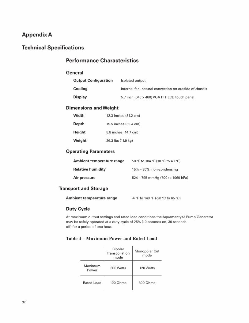
Table 6 – Electromagnetic Testing
Immunity Test IEC (60)601-1-2:2001 Test Level
Conducted emission DIN EN 55011, FCC Part 18, Class A,non-consumer class
150 kHz – 30 MHz
Radiated emission DIN EN 55011, FCC Part 18, Class A, non-consumer class
30 MHz – 1 GHz
Electrostatic discharge DIN EN 61000-4-2
± 6 kV Contact discharge ± 8 kV Air discharge

40
Immunity to electromagnetic fields DIN EN 61000-4-3
10 V/m 80 – 2500 MHz
Immunity to conducted fast transients DIN EN 61000-4-4
Burst: ± 2 kV power mains ± 1 kV signal lines
Immunity to conducted slow transients DIN EN 61000-4-5
Surge 1.2/50µs: ± 2 kV unsym / ± 1 kV sym power mains
Immunity to conducted disturbances Induced by RF-fields DIN EN 61000-4-6
10 Vrms 150 kHz – 80 MHz power mains / signal lines
Voltage dips, short interruptions DIN EN 61000-4-11
Complies
Harmonic current emission DIN EN 61000-3-2, Class A
Complies
VoltagefluctuationandflickerDIN EN 61000-3-3
Complies
The Aquamantys3 Pump Generator meets the electromagnetic compatibility requirements of IEC60601-1-2:2007.
• Class A Device Statement: (Section 15.105(a) of the FCC Rules)
Note: This equipment has been tested and found to comply with the limits for a Class A digital device, pursuant to part 15 of the FCC Rules. These limits are designed to provide reasonable protection against harmful interference when the equipment is operated in a commercial environment. This equipment generates, uses, and can radiate radio frequency energy and, if not installed and used in accordance with the instruction manual, may cause harmful interference to radio communications. Operation of this equipment in a residential area is likely to cause harmful interference in which case the user will be required to correct the interference at his own expense.
• Intentional Radiator Statement: (Section 15.19(a3) of the FCC Rules)
Thisdevicecomplieswithpart15oftheFCCRules.Operationissubjecttothefollowingtwoconditions: (1) This device may not cause harmful interference, and (2) this device must accept any interference received, including interference that may cause undesired operation.
41
Output Characteristics
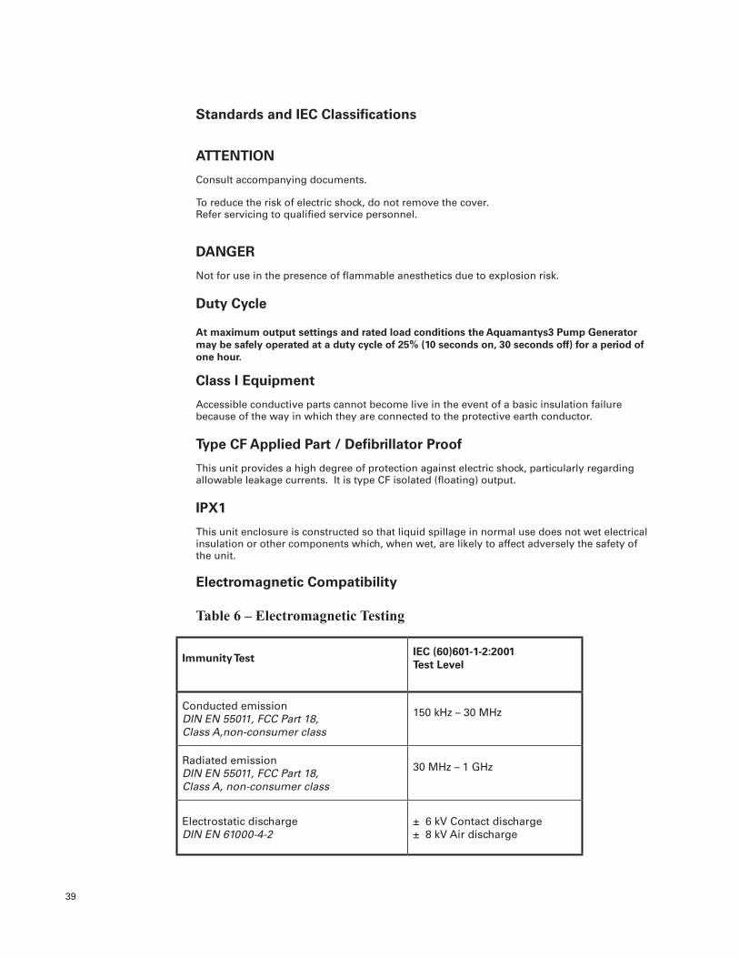
RF Output
Adjustable Power Increment
Monopolar: 1 to 40 watts 1 watt
40 to 100 watts 5 watt
100 to 120 watts 10 watt
Bipolar: 5 to 40 watts 1 watt
40 to 100 watts 5 watt
100 to 300 watts 10 watt
Table 7 – RF Output
Output Mode Maximum Open Circuit
Voltage
Maximum Short Circuit
Current
Maximum Power Setting
Rated Load
Frequency Crest Factor
Vpk-pk (Vpk) Arms Watts Ohms kHz
Bipolar Transcollation
mode540 (270) 2.60 300 100 370 <1.6
Monopolar Cut mode
1550 (775) 1.35 120 300 370 <1.6
Saline Flow Rate
Priming Flow Rate 36 - 154 mL/min
Priming Time < 13 seconds
Bipolar Transcollation Flow Rate 0.5 to 47 mL/min, depending on power setting
Figure A-1. Saline Flow Rate vs. Bipolar Power Setting
0
10
20
30
40
50
0 50 100 150 200 250 300
Output Pow er (w atts)
Flow
Rat
e (c
c/m
in)
Low Medium High
Output Power (watts)

42
Figure A-2. Bipolar Output Voltage vs. Power Setting (at Rated Load)
0
50
100
150
200
250
300
0 50 100 150 200 250 300
Pow er Setting (w atts)
Out
put V
olta
ge
Volts RMS Volts Peak
Figure A-3. Bipolar Output Power vs. Load Resistance
0
50
100
150
200
250
300
350
0 200 400 600 800 1000
Output Impedance (ohms)
Out
put P
ower
(wat
ts)
150W 300W
Figure A-4. Bipolar Output Power vs. Power Setting (at Rated Load)
0
50
100
150
200
250
300
0 50 100 150 200 250 300
Pow er Setting (w atts)
Out
put P
ower
(wat
ts)
Power Settings (watts)
Power Settings (watts)

43
Figure A-5. Monopolar Output Voltage vs. Power Setting (at Rated Load)
0
50
100
150
200
250
300
350
20 40 60 80 100 120
Pow er Setting (w atts)
Out
put V
olta
ge
Volts RMS Volts Peak
Figure A-6. Monopolar Output Power vs. Load Resistance
0
20
40
60
80
100
120
140
0 200 400 600 800 1000 1200 1400 1600 1800 2000
Output Impedance (ohms)
Out
put P
ower
(wat
ts)
60W 120W
0
20
40
60
80
100
120
140
0 200 400 600 800 1000 1200 1400 1600 1800 2000
Output Impedance (ohms)
Out
put P
ower
(wat
ts)
60W 120W
0
20
40
60
80
100
120
140
0 200 400 600 800 1000 1200 1400 1600 1800 2000
Output Impedance (ohms)
Out
put P
ower
(wat
ts)
60W 120W
Figure A-7. Monopolar Output Power vs. Power Setting (at Rated Load)
0
20
40
60
80
100
120
0 20 40 60 80 100 120
Pow er Setting (w atts)
Out
put P
ower
(wat
ts)
Power Settings (watts)
Power Settings (watts)

44
Accessories: Aquamantys®3 System Power Cords
Table 8 – Compatible Power Cords
Part # Region Voltage Length Connectors
30-501-1 North America 115V 12 feet IEC 60320-C13 to NEMA 5-15
30-502-1 Europe 230V 4.5 m IEC 60320-C13
to Europlug CEE 7/7
30-503-1 Japan 100V 4.5 m IEC 60320-C13
to JIS 8303
30-504-1 United Kingdom 230V 4.5 m IEC 60320-C13
to BS 1363
30-505-1 Denmark 230V 2.5 mIEC 60320-C13
to DK-2-8A
30-506-1 Australia 230V 2.5mIEC 60320-C13
to AS/NZS 3112:2000
30-507 Africa 230V 2.5 mEC 60320-C13 to SANS 164-1
Table 9 –Accessories
34-102-1 Aquamantys3 Maintenance Cassette
Allspecificationsarenominalandsubjecttochangewithoutnotice.

Appendix B
Periodic Safety and Output Accuracy Testing
Warnings: All servicing should be referred to qualified service personnel. It is recommended that you contact the Salient Surgical Technologies Customer Service Department to have the Aquamantys3 Pump Generator serviced
Burn Hazards:
High frequency, high voltage signals are present on the output circuit when activated. These signals can cause severe burns. Extreme caution must be used when testing the output of the generator.
Load resistors used to test the output of the generator will become extremely hot. Use extreme caution to avoid any contact. All load resistors must be properly mounted and isolated from any flammable materials.
The Aquamantys3 generator power cord must be connected to a properly grounded receptacle during both normal use and testing. Do not use extension cords or adapter plugs.
Precautions: All warnings and precautions accompanying the Aquamantys3 generator should be read and understood prior to attempting any testing of the unit.
When performing accuracy measurements, keep all leads as short as possible and keep leads away from metallic surfaces.
Observe stated duty cycle when testing the generator. The Aquamantys3 generator is not intended for continuous activation for extended periods of time.
Equipment RequiredThe following equipment will be required to complete the periodic safety and accuracy testing:
• Aquamantys3MaintenanceCassette
Instrumentation capable of accurately measuring AC current values up to 3 Amps at 370 kHz.
• Resistive(non-reactive)loadsof100ohms±5%(300wattsminimum),200ohms ±5% (150 watts minimum) and 300 ohms ±5% (120 watts minimum).
• Aneutralelectrode(returnpad)connectorwiththepadcutoffandthetwoleads shorted together.
• Miscellaneousconnectorsandcablingtoestablishallrequiredconnections.All test cables should be rated for at least 3 amperes and cable lengths should be kept as short as possible.
• Graduatedcylinders(orotherfluidvolumemeasurementvessel)andastopwatchformeasuringflowrateaccuracy.
• Aneutralelectrode(returnpad)connectorwiththepadcutoffandavariableresistance of at least 0 to 230 ohms connected between the two neutral electrode leads.
45

46
Introduction to the Aquamantys®3 Maintenance Cassette
Please refer to Sections 2 through 4 of the Aquamantys3 Generator User Manual for initial setup and general use instructions for the Aquamantys3 Generator.
The Aquamantys3 Maintenance Cassette is a non-clinical use component which is used to enable specific functions in the Aquamantys3 Pump Generator which allow the user to verify the output accuracy of the generator and also to perform various other functions such as software upgrades. The cassette is inserted into the generator’s cassette slot. The attached 4mm banana receptacles and tubing connectors allow the user to connect the generator outputs to measurement instrumentation. The graphic user interface on the generator’s display guides the user through the various output functions available.
A maintenance cassette is shipped with each generator. Should the cassette be misplaced, additional cassettes are available by contacting your Salient Surgical Technologies service representative.
Using the Aquamantys®3 Maintenance Cassette
Main Menu
Upon insertion of the cassette into the generator cassette slot, the menu shown above will be displayed. The desired function is accessed by touching the appropriate button.
Flow Rate Tests
The Flow Rate Tests provide a means for the user to verify the accuracy of the saline pump. When the Flow Rate Tests are selected from the main menu,youwillbedirectedtoconnectthefluidsupply to the cassette input tubing (clear tubing withwhitebarb).Thefluidsupplyneednotbe0.9% saline solution as would normally be used inconjunctionwiththeAquamanys3sealingdevices; a container of ordinary tap water is sufficient for these measurements. You will also be instructed to direct the output tubing (clear tubingwithblackbarb)totheflowmeasurementdevice.Theflowmeasurementdeviceisagraduatedcylinderorothermeansofmeasuringthedispensedfluidvolumewithsufficientaccuracy.Whenalltheproperfluidconnectionshavebeenmade,press“Continue”.

47
It is now necessary to prime the cassette tubing sothatallsubsequentflowratemeasurementsmaybeaccuratelytimed.Pressingthe“Prime”button will cause the generator’s pump to run for approximately 9 seconds. When the prime cycle is completed, the generator will automatically advance to the next screen.
Thereare3flowratesavailableforflowrateaccuracy measurements. The first is 10 ml per minute; the second is 47 ml per minute and priming rate (150 ml per minute). Select the desiredflowrateandpress“Continue”.
Thelast“FlowRateTests”screenallowsyoutoturnthegenerator’spumponandoffattheflowrate which was selected on the previous screen. Theselectedflowratewillalsobedisplayedalongwith the acceptable accuracy tolerance (+/- 20%) andtherangeofacceptableflowrates.
Makesurethatthetubinglabeled“OUT”isdirectedintovolumemeasurementvesselandpreparethestopwatch.Whenready,Press“PumpON”andstartthestopwatch.Thepumpwillrununtil“PumpOFF”ispressed.Thevolumeoffluidthatshouldbedispensedisdependentupon the accuracy of the measurement vessel being used. For example, if 1 ml can be accurately measured,thenmorefluidshouldbedispensedthanif0.5mlcanbeaccuratelymeasured.
Whentheselectedflowrateaccuracymeasurementsarecompleted,press“Exit”.Youwillbereturnedtotheflowrateselectionscreenwhereyoucanselectanotherflowratetobetested,orpress“Exit”toreturntotheMainMenu.

48
Power Output Tests
The Power Output Tests provide a means for the user to verify the accuracy of the RF energy output. When the Power Output Tests are selected from the main menu, you will first select the power output type to be measured. Select either “BipolarSealing”or“MonopolarCutting”.
Bipolar Sealing
You will be instructed to attach the 100 ohm non-reactive load across the two (red and white) RF output leads.
It will also be necessary at this time to attach a current probe to measure the current that is developed through the resistor when the RF output is activated.
Press“Continue”whenallconnectionshavebeencompleted.

Select the power output level to be verified andpress“Continue”.Itiscustomarytocheckboth the 50% and 100% of maximum power settings – in this case, 150W and 300W.
Press“RFON”toactivatetheRFoutputandperform measurements. The RF output will remainonuntil“RFOFF”ispressed.Duringthis testing, please observe the duty cycle recommendations published in this User Guide.
The selected power setting will also be displayed along with the acceptable accuracy tolerance (+/- 20%) and the range of acceptable power measurements. The power should be calculated as I2R (the square of the measured current multiplied by the 100 ohm resistance value).
Monopolar Cutting
If you select Monopolar Cutting from the Power Output Tests Menu, you will be instructed to attach the 300 ohm non-reactive load between the white RF output lead and a return electrode connector (with conductors shorted) plugged into the Neutral Electrode connector on the generator. It will also be necessary at this time to attach a current probe to measure the current that is developed through the resistor when the RF output is activated.
The remainder of the monopolar cutting power output test is identical to the steps performed in the bipolar sealing instructions above.
Neutral Electrode Contact Monitor Tests
The Neutral Electrode Contact Monitor Tests provide a means for the user to verify the accuracy of the neutral electrode resistance measurement circuit. For these measurements, you will use the neutral electrode connector with a variable resistance replacing the pad as described in the Equipment Required section at the beginning of this appendix.
49

When the Power Output Tests are selected from the main menu, you will first be instructed to set the variable resistance to approximately 20 ohms and to insert the connector into the NE receptacle on the generator. After doing this, the neutral electrode receptacle should be illuminated green (indicating that the neutral electrode resistance is withintheacceptablerange).Press“Continue”.
You will next be instructed to slowly reduce the variable resistance until the NE receptacle on the generator transitions from green to red illumination (indicating that the resistance is no longer within the acceptable range.) Remove the NE connector from the generator and measure the value of the variable resistance. It should be between5and11ohms.Press“Continue”.
Set the variable resistance to approximately 170 ohms and reconnect it to the generator. After doing this, the neutral electrode receptacle should be illuminated green (indicating that the neutral electrode resistance is within the acceptable range).Press“Continue”.
You will next be instructed to slowly increase the variable resistance until the NE receptacle on the generator transitions from green to red illumination (indicating that the resistance is no longer within the acceptable range.) Remove the NE connector from the generator and measure the value of the variable resistance. It should be between 187.2 and 228.8 ohms.
This completes the Contact Monitor Tests – press “Exit”toreturntothemainmenu.
50

Upgrade Software
The Upgrade Software selection is not functional for this version of the Aquamantys3 Pump Generator.
RF Output Safety Verification (RF Leakage Current)
Please refer to Sections 2 through 4 of the Aquamantys3 Pump Generator user manual for initial setup and general use instructions for the Aquamantys3 Pump Generator.
RF leakage current measurements should be performed in accordance with the most current release of IEC 60601-2-2 (Particular requirements for the safety of high frequency surgical equipment).
Monopolar Cutting Leakage Current Measurements
For monopolar RF leakage the appropriate test configuration is with the neutral electrode isolated from earth ground at high frequencies.
Follow the instructions for monopolar cutting power output tests above. Select the 150W test point.
The monopolar leakage current to earth at 150W is measured in sequence:
1. From the device cutting electrode to earth ground through a 200 ohm resistance. Turn150WRFoutput“ON”andmeasureleakage current as shown.
2. From the neutral electrode to earth ground through a 200 ohm resistance. Turn150WRFoutput“ON”andmeasureleakage current as shown.
The monopolar RF leakage current measured should not exceed 150 mA.51

Bipolar Sealing Leakage Current Measurements
Follow the instructions for bipolar sealing power output tests above. Select the 150W test point.
The bipolar leakage current to earth at 150W is measured in sequence first from one electrode to earth ground through a 200 ohm resistance, and then the same is measured from the other electrode as shown below:
Leakage test #1
Leakage test #2
The bipolar RF leakage current measured from either electrode should not exceed 87 mA.
52

53
Appendix C
New Unit Warranty
LIMITED EXPRESS WARRANTY
For one (1) year from the date of shipment from Salient Surgical Technologies, Inc., if a generator or cart is found, to Salient Surgical’s satisfaction, to be inoperable during normal and proper use in accordance with applicable instructions, Salient Surgical Technologies, Inc. will repair or replace the product, at its sole option, provided the product is returned, freight prepaid, in accordance with all return packaging and shipping instructions. A product repaired or replaced under this warranty will be warranted for the remainder of the original warranty period.
SALIENT SURGICAL TECHNOLOGIES, INC. MAKES NO OTHER WARRANTIES WITH RESPECT TO THE PRODUCT AND EXPRESSLY DISCLAIMS ALL OTHER WARRANTIES, EXPRESS OR IMPLIED, AS TO MERCHANTABILITY, FITNESS FOR A PARTICULAR PURPOSE OR ANY OTHER MATTER. IN NO EVENT SHALL SALIENT SURGICAL TECHNOLOGIES, INC. BE LIABLE FOR ANY CONSEQUENTIAL DAMAGES.
THE ABOVE WARRANTY IS VOID ON ANY PRODUCT WHICH HAS BEEN MODIFIED OR REPAIRED OTHER THAN BY SALIENT SURGICAL OR AN AUTHORIZED REPRESENTATIVE; IMPROPERLY INSTALLED, USED, MAINTAINED, OR STORED; OR SUBJECT TO ABUSE, MISUSE, NEGLECT, OR ACCIDENT. SALIENT IS NOT RESPONSIBLE FOR DAMAGE, OR ANY OTHER LOSS DURING RETURN SHIPMENT.
Refurbished Unit Warranty
PLEASE NOTE : For the refurbished Aquamantys3 Pump Generators, Model number 40-404-1R, the Limited Express Warranty described below replaces and voids the New Unit Limited Express Warranty found above.
LIMITED EXPRESS WARRANTY
For six (6) months from the date of shipment from Salient Surgical Technologies, Inc., if a refurbished Aquamantys3 Pump Generator is found, to Salient’s satisfaction, to be inoperable during normal and proper use in accordance with applicable instructions, Salient Surgical Technologies, Inc. will repair or replace the product, at its sole option, provided the product is returned, freight prepaid, in accordance with all return packaging and shipping instructions. A product repaired or replaced under this warranty will be warranted for the remainder of the original warranty period.
SALIENT SURGICAL TECHNOLOGIES, INC. MAKES NO OTHER WARRANTIES WITH RESPECT TO THE PRODUCT AND EXPRESSLY DISCLAIMS ALL OTHER WARRANTIES, EXPRESS OR IMPLIED, AS TO MERCHANTABILITY, FITNESS FOR A PARTICULAR PURPOSE OR ANY OTHER MATTER. IN NO EVENT SHALL SALIENT SURGICAL TECHNOLOGIES, INC. BE LIABLE FOR ANY CONSEQUENTIAL DAMAGES.
THE ABOVE WARRANTY IS VOID ON ANY PRODUCT WHICH HAS BEEN MODIFIED OR REPAIRED OTHER THAN BY SALIENT OR AN AUTHORIZED REPRESENTATIVE; IMPROPERLY INSTALLED, USED, MAINTAINED OR STORED; OR SUBJECT TO ABUSE, MISUSE, NEGLECT OR ACCIDENT. SALIENT IS NOT RESPONSIBLE FOR DAMAGE OR ANY OTHER LOSS DURING RETURN SHIPMENT.


Salient Surgical Technologies, Inc. 180 International DrivePortsmouth, NH 03801
USA www.salientsurgical.com
Customer Service: Tel: 866.777.9400
Fax: 866.222.0900
Outside the U.S.: +1.603.742.1515 +1.603.742.1488
U.K. Telephone numbers: Tel: 0808.101.1727
Fax: 0808.101.1726
© Copyright 2010 Salient Surgical Technologies, Inc. All rights reserved. SALIENT, the SALIENT logos, AQUAMANTYS, TRANSCOLLATION, SIMPLY BETTER
SURGERY, and ADVANCED ENERGY FOR ADVANCED OUTCOMES are trademarks of Salient Surgical Technologies, Inc.
70-10-1376 Rev F