Embed Size (px)
Citation preview

User Guide
C O M M A N D E R GGppmodel sizes 1 to 4
0.75kW to 110kW(1HP to 150HP)
C O M M A N D E R GGpp LVLVmodel sizes 1 to 3
0.37kW to 22kW(0.5HP to 30HP)
General Purpose Variable Speed Drivefor induction motors
Part Number: 0451-0024
Issue Number: 2

General information
The manufacturer accepts no liability for anyconsequences resulting from inappropriate ,negligent or incorrect installation or adjustment ofthe optional operating parameters of the equipmentor from mismatching the variable speed drive(Drive) with the motor.
The contents of this User Guide are believed to becorrect at the time of printing. In the interests of acommitment to a policy of continuous developmentand improvement, the manufacturer reserves theright to change the specification of the product orits performance, or the contents of the User Guide,without notice.
All rights reserved. No parts of this User Guide maybe reproduced or transmitted in any form or by anymeans, electrical or mechanical includingphotocopying, recording or by any information-storage or retrieval system, without permission inwriting from the publisher.
Important...Drive software version
This product is supplied with the latest version ofuser-interface and machine-control software. If thisproduct is to be used with other Control Techniquesvariable speed drives in an existing system, theremay be some differences between their softwareand the software in this product. These differenceswill cause a difference in functions. This may alsoapply to variable speed drives returned from aControl Techniques Service Centre.
If there is any doubt, contact a Control TechniquesDrive Centre.
Copyright © March 2000 Control Techniques Drives Ltd
Author: RFD
Issue Code: gpxu2
Issue Date: March 2000
S/W Version: V03.XX.07 onward

Commander GP User GuideIssue code: gpxu2d2 i
Chapter
1 Introduction 1-1
1.1 How this User Guide can help you 1-1
1.2 Model sizes 1-1
1.3 Configuration layers 1-2
1.4 Default configurations 1-2
1.5 Operating mode 1-2
1.6 User-interface modes 1-2
1.7 Macro configurations 1-3
1.8 Plug-in option modules 1-4
1.9 Serial communications 1-4
2 Getting Started 2-1
2.1 How to use this chapter 2-1
2.2 Making signal and power connections 2-1
2.3 Introduction to the display and keypad 2-6
Display and keypad 2-6
Resetting the Drive 2-7
2.4 Working with software parameters 2-7
Parameters 2-7
Types of parameter 2-7
Adjusting parameter values 2-7
Making new values effective, and savingthem 2-7
Parameter 0.00 2-8
2.5 How macro configurations change thearrangement of the Menu 0 parameters 2-8
2.6 Initial setting up 2-9
Restoring the Drive to a defaultconfiguration 2-9
Enabling Macro 1 2-10
Configuring the Drive for the motor 2-10
Autotune 2-12
Changing the user interface mode 2-12
2.7 Operating instructions 2-13
Terminal mode 2-13
Keypad mode 2-14
Trip and enable 2-14
2.8 Setting up operating limits 2-15
Minimum and maximum frequencies 2-15
Acceleration rate 2-15
Deceleration rate 2-15
Braking resistor 2-15
Torque producing current limit 2-16
Voltage-control modes 2-16
Boost voltage 2-17
Voltage/frequency characteristic 2-17
3 Setting Up the Drive(Macro Configurations) 3-1
3.1 How to use this chapter 3-1
3.2 Enabling a different macro configuration3-1
3.3 Macro 0 General purpose(default configuration) 3-2
3.4 Macro 1 Easy mode 3-9
3.5 Macro 2 Motorized potentiometer 3-15
3.6 Macro 3 Preset frequencies 3-21
3.7 Macro 4 Torque control 3-27
3.8 Macro 5 PID (set-point control) 3-33
3.9 Macro 6 Axis-limit control 3-38
3.10 Macro 7 Brake control 3-45
Contents

Commander GP User GuideIssue code: gpxu2d2ii
Appendix
A Programming Instructions A-1
A.1 Electrical connections A-1
A.2 Preparation A-1
A.3 Status mode A-2
A.4 Displaying the parameternumber in Status mode A-2
A.5 Entering Parameter modeand returning to Status mode A-2
A.6 Selecting a parameter to access A-3
A.7 Changing the value of a parameter A-4
A.8 Saving new parameter values A-6
A.9 Flashing and non-flashing digits A-6
A.10 Negative values A-6
A.11 Changing the settingof a bit parameter A-6
A.12 Selecting a different option A-7
A.13 Restoring the Drive to a defaultconfiguration A-7
A.14 Summary of key operation A-7
B Security B-1
B.1 User-defined Security B-1
B.2 Setting-up User Security B-1
B.3 Unlocking User Security B-1
B.4 Locking User Security B-1
B.5 Summary B-1
C Signal Connections C-1
D Menu 0 Parameters D-1
D.1 Introduction D-1
D.2 Fixed-function parameters commonto all macro configurations D-2
D.3 Parameters specific to the macroconfigurations D-8
E Diagnostics E-1
E.1 Status indications E-1
E.2 Alarm indications E-1
E.3 Trip codes E-2

Commander GP User GuideIssue code: gpxu2 Introduction 1-1
1 Introduction
1.1 How this User Guidecan help you
If this is your first encounter with aCommander Gp Drive, read this User Guidebefore referring to the accompanyingInstallation Guide.
This User Guide is arranged on a step-by-step basisto lead you through the following:
• Learning how to operate the CommanderGp (Drive)
• When to refer to the Installation Guide• Setting up the Commander Gp for basic
applications
Advanced programming of theCommander Gp
For advanced programming of the Commander Gp,refer to the Commander Gp Advanced User Guide. Thiscontains descriptions of all the advancedparameters, as well as additional information, andcan be obtained from the Drive Centres anddistributors listed at the end of this User Guide.
The advanced parameters in software versionV03.01.07 onward can be accessed by use of theUD71 Basic serial communications large option module(see Serial communications later in this chapter).
Warning
Variable speed drives may behazardous if misused. Carefullyfollow the instructions in thisUser Guide and the InstallationGuide.
1.2 Model sizes
This User Guide refers to the models listed below.
Model size Model code Nominalrating for
standard ACmotors
kWat 380V
HPat 460V
GPD 1401 0.75 1.0
GPD 1402 1.1 1.5
GPD 1403 1.5 2.0
GPD 1404 2.2 3.0
GPD 1405 4.0 5.0
GPD 2401 5.5 7.5
GPD 2402 7.5 10
GPD 2403 11.0 15
GPD 3401 15.0 25
GPD 3402 18.5 30
GPD 3403 22.0 30
GPD 3404 30.0 40
GPD 3405 37.0 50
GPD 4401 45.0 75
GPD 4402 55.0 100
GPD 4403 75.0 125
GPD 4404 90.0 150
GPD 4405 110.0 150
Model size Model code Nominal ratingfor standardAC motors
KWat 380V
HPat 460V
GPD 1201 0.37 0.5
GPD 1202 0.55 0.75
GPD 1203 0.75 1.0
GPD 1204 1.1 1.5
GPD 1205 2.2 3.0
GPD 2201 3.0 4.0
GPD 2202 4.0 5.0
GPD 2203 5.5 7.5
GPD 3201 7.5 10
GPD 3202 11 15
GPD 3203 15 20
GPD 3204 22 30

Commander GP User GuideIssue code: gpxu21-2 Introduction
1.3 Configuration layers
The Drive has three layers of configuration, startingfrom the base layer (1) as follows:
1. Default configuration
2. User-interface mode
3. Macro configuration
Each of the upper layers (2, 3) is superimposed on itspreceeding layer.
1.4 Default configurations
The Drive has a separate default configuration for theAC supply conditions in Europe or in the USA. Thesetwo default configurations are distinguished asfollows:
European AC supply voltage at 50HzUSA AC supply voltage at 60Hz
The Drive is despatched from the factory in theappropriate default configuration for the continentin which it is to be sold. The default configurationis Macro 0 (described in Macro configurations later inthis chapter).
The default configuration also defines the followingfunctions:
Europe• Ability to select positive-logic for the digital
control inputs• Ability to adjust the current-loop PI gains
USA• Ability to select digital control by two or
three wires• Frequency demand indication
(These functions apply to Macro 0 only.)
Key used in this User Guide
The following key denotes the defaultconfiguration:
EUR> 50Hz AC supply (Europe)USA> 60Hz AC supply (USA)
When no key is stated, the information applies toboth default configurations.
1.5 Operating mode
For use with standard AC induction motors.
The Drive applies power to the motor at frequencieswhich are controlled by the user. The motor speedis a result of the output frequency of the Drive andslip due to the mechanical load.
The Drive can power a number of motors connectedin parallel (each motor must be protected againstoverload; this is described in the Installation Guide).
The Drive can improve the performance of themotor by applying the following:
• Slip compensation• Fixed boost or Open-loop Vector operation
Fixed boost applies a fixed voltage boost at lowfrequencies.
Open-loop Vector operation maintains almostconstant flux by dynamically adjusting themotor voltage according to the load on themotor.
1.6 User-interface modes
The motor can be started and stopped, thedirection of rotation reversed and the speedchanged by operation of the Drive in either of thefollowing user-interface modes:
Terminal modeApplying signals from electrical contacts, asystem controller or PLC to digital and analoginputs on the Drive.For the USA default configuration, the Drive canbe configured for digital control by momentarycontacts.
Keypad modeManual operation of the keypad on the frontpanel of the Drive. Minimal signal connectionsare made to the Drive.

Commander GP User GuideIssue code: gpxu2 Introduction 1-3
1.7 Macro configurations
The Drive can be used to control the motor speed invarious ways for different types of application. Toreduce the number of adjustments to the Drive foreach type of application, eight macro configurations(0 to 7) are available.
Each macro configuration requires specific signalconnections to be made to the Drive.
The macro configurations are as follows:
Macro 0General purpose (default configuration)
Analog frequency control for general-purposeapplications.
The output frequency of the Drive is controlled by afrequency reference. The motor speed will follow thefrequency reference so long as the maximumpermissible output current of the Drive is notexceeded. These principles also apply to all othermacro configurations except Macro 4.
The macro configuration can be used in eitherKeypad or Terminal mode.
The frequency can be controlled in either of thefollowing ways...
• Terminal mode: An analog frequencyreference signal applied to the Drive
• Keypad mode: By a user pressing keys onthe front panel of the Drive
Macro 1Easy mode
Frequency control for basic applications. This issimilar to Macro 0, except, for simplicity, feweradjustments are required.
The macro configuration can be used in eitherKeypad or Terminal mode.
The principles of controlling motor speed are thesame as for Macro 0.
Macro 2Motorized potentiometer
The frequency is controlled incrementally byoperation of up and down contacts.
The macro configuration can be used in Terminalmode only.
The principles of controlling motor speed are thesame as for Macro 0.
Macro 3Preset frequencies
Four preset frequencies that are selected by externalcontacts.
The macro configuration can be used in Terminalmode only.
The principles of controlling motor speed are thesame as for Macro 0.
Macro 4Torque control
The motor torque is defined by a torque demand. The motor speed will vary continuously as a resultof the difference between the load torque and thetorque demand up to a maximum speed which isdefined by a speed over-ride level.
The torque demand is supplied by an analog torquereference signal that is applied to the Drive.
The macro configuration can be used in Terminalmode only.
Macro 5PID control
The Drive is operated with a frequency referenceand an analog feedback device in order todynamically maintain the speed to a user-definedset-point under PID control.
The macro configuration can be used in Terminalmode only.
The principles of controlling motor speed are thesame as for Macro 0.
Macro 6Axis-limit control
Axis-limit control is used for applications whichrequire the process to be automatically stoppedwhen a position limit has been reached. A bipolar orunipolar frequency reference can be used.
The macro configuration can be used in Terminalmode only.
The principles of controlling motor speed are thesame as for Macro 0.
Macro 7Brake control
Frequency control with brake control for crane orhoist applications.
The macro configuration can be used in Terminalmode or Keypad mode.
The principles of controlling motor speed are thesame as for Macro 0.
Commander GP User GuideIssue code: gpxu21-4 Introduction
1.8 Plug-in option modules
Operation of the Drive can be extended by the useof plug-in option modules. The following modulesare available from the supplier of the Drive; anappropriate User Guide is included with eachmodule:
Small option modulesUD50 Additional I/OUD55 Cloning (parameter copying)
Large option modulesUD71 RS232/RS485 serial
communications
1.9 Serial communications
The Drive can be configured and fully controlledfrom a system controller or PLC operating on aRS232 or a 4-wire RS485 serial communications link. A Basic serial communications large option modulemust be fitted in the Drive. More information canbe obtained from a Drive Centre or distributorlisted at the end of this User Guide.
Serial communications can be used in conjunctionwith Terminal mode or Keypad mode.

Commander GP User GuideIssue code: gpxu2 Introduction 1-5
User interface
Functions of the software (controlled by the macro configurations)
Drive
Power circuits
Display and keypad
External control and monitoring (analog and digital)
AC supply
User control
Frequency reference selection
Minimum and maximum frequency limits
Skip frequencies
Acceleration and deceleration ramps
S-ramp
MonitoringCurrent limitStop modeSpinning motor sync.
Voltage control
Motor parameters
PWM switching frequency
Monitoring
Control
DC bus
Optional braking resistor
Figure 1–1 Block diagram of the Drive showing the main functions of the software,and power connections (signal connections vary according to themacro configuration)

Commander GP User GuideIssue code: gpxu21-6 Introduction

Commander GP User GuideIssue code: gpxu2 Getting Started 2-1
2 Getting Started
2.1 How to use this chapter
It is recommended that you follow the instructionsin this chapter in the order that they appear. Youwill be led through the initial stages of setting upthe Drive (in Macro 1 Easy mode) as well as being ableto familiarize yourself with operating the Drive.
Warning
The Drive must be operatedonly by personnel having thenecessary training orexperience.
Warning
If this is the first time theDrive has been operated,ensure that no damage orsafety hazard could arise fromthe motor startingunexpectedly.
Warning
The motor must be fixed downand the shaft guarded againstinadvertent contact.
Warning
Do not change parametervalues without carefulconsideration; wrong valuesmay cause damage or a safetyhazard.
Notes
Keep a note of changes
When changing the values of parameters,make a note of the new values in case theyneed to be entered again.
Saving the changes
For new parameter-values to apply afterthe AC supply to the Drive is interrupted,new values must be saved. This is describedin Saving new parameter-values in Appendix AProgramming Instructions.
2.2 Making signal and powerconnections
Warning
Stored charge
The Drive contains capacitorsthat remain charged to apotentially lethal voltage afterthe AC supply has beendisconnected. If the Drive hasbeen energized, the AC supplymust be isolated at leastten minutes before work maycontinue.
Warning
Isolation
The control circuits andterminals are isolated from thepower circuits only by basicinsulation to IEC664–1. Theinstaller must ensure that allexternal control circuits areseparated from human contactby at least one layer ofinsulation rated for use at theAC supply voltage.
For instructions on removing the terminal covers,see Mounting the Drive and RFI filter in Chapter 2Installing the Drive in the Installation Guide.
Figure 2–1 Removing the terminal covers foraccess to the connectors

Commander GP User GuideIssue code: gpxu22-2 Getting Started
1 11
21 31
Figure 2–2 Location of the signal connector
Figure 2–3 Locations of the power connectors
1. Observe the safety warnings and cautions givenin Chapter 1 Safety information of the InstallationGuide and in this chapter.
2. Refer to the following:
• Chapter 2 of the Installation Guide in orderto install the Drive
• Figure 2–2 for the location of thesignal connector
• Figure 2–3 for the locations of thepower connections
• Figure 2–5 or 2–6 in this chapter in order tomake the signal and power connections foroperation in Terminal or Keypad mode. Note that Macros 2, 3, 4, 5, 6 operate only inTerminal mode. If one of these macroconfigurations is to be enabled after theinitial setting up covered in this chapter, youmay wish to set up the Drive now inTerminal mode in order to learn how tooperate it in this mode.
Signal connector for all models The twoterminal blocks of the signal connector can beunplugged from the Drive by pulling themdownward.
Power connector for model sizes 1and 2 The power connector can be unpluggedfrom the Drive by pulling it downward.
Power connections to model sizes 3and 4 The power connections are made toM10 studs located in the power section of theDrive.
3. Note that the default user-interface mode isas follows:
Continent User-interfacemode
EUR Terminal
USA Keypad
(Instructions for changing the user-interfacemode are given later.)

Commander GP User GuideIssue code: gpxu2 Getting Started 2-3
4. When connecting a motor to the Drive, observethe following:
• Preferably the motor should be identical tothe motor that is to be used in theapplication, but this is not essential.
• The motor shaft must not be attached toany equipment, or exposed.
5. No motor thermistor connection is required atthis stage, but a thermistor will be requiredlater if the Drive is to be operated in any macroconfiguration except Macros 1 and 5. WhenMacro 1 or Macro 5 is enabled, the thermistor isignored by the Drive. (Instructions forconnecting a motor thermistor to the signalconnector are given for each macroconfiguration in Chapter 3 Setting Up the Drive.)
Warning
After having made controlconnections, carefully checkthat terminal 30 is open-circuitto ensure the Drive is in theStop state when the AC supplyis first connected.
6. After re-fitting the terminal cover, connect theDrive to the AC supply.

Commander GP User GuideIssue code: gpxu22-4 Getting Started
Status relayDrive healthy
0V common
Analog frequency reference 1 (remote)
SPEED
TORQUE
0V common
Connections for single-ended input
signal
Connections for differential input signal
0V common
Signal connector
Analog frequency reference 2 (local)
AT SPEED
RESET
JOG SELECT
RUN FORWARD
RUN REVERSE
LOCAL / REMOTE
External trip
0V common
0V common
LOCAL
REMOTE
Power terminals
Optional RFI filter
Stop Start / Reset
Thermal protection device
Optional braking resistor
Refer to the Installation Guide for cable sizes and fuse ratings
Refer to the Installation Guide for sizing of the optional braking resistor
Figure 2–5 Power connections, and signal connections for Terminal mode (Macro 1 only)

Commander GP User GuideIssue code: gpxu2 Getting Started 2-5
Status relayDrive healthy
SPEED
TORQUE
0V common
Signal connector
AT SPEED
RESET
External trip
0V common
0V common
EncoderPower
Optional RFI filter
Stop Start / Reset
Thermal protection device
Optional braking resistor
Refer to the Installation Guide for cable sizes and fuse ratings
Refer to the Installation Guide for sizing of the optional braking resistor
Figure 2–6 Power connections, and signal connections for Keypad mode (Macro 1 only)

Commander GP User GuideIssue code: gpxu22-6 Getting Started
2.3 Introduction to thedisplay and keypad
Display and keypad
The display and keypad are used for the following:
• Reading and changing the values of softwareparameters that are used to configure,control and monitor the Drive
• Displaying the operating status of the Drive• Displaying fault and trip codes
Programming keys
Control keys
Run Stop Reset
Forward /Reverse
Upper display
Lower display
Figure 2–7 Display and keypad
Display
The display has three display modes as follows...
• Status modeUsed to indicate the status of the Drive
• Parameter modeUsed for selecting a parameter to edit
• Edit modeUsed for editing the selected parameter
... and shows the following:
Display Display mode
Status Parameter Edit
Upper Value ofparameter (0)
Value ofparameter (0)
Value ofparameter (0)(selected digitflashes)
Lower Status of theDriverdY
Parameternumber (0.10)
Parameternumber (0.10)
Operating instructions for the display and keypadare given in Appendix A Programming Instructions.
Programming keys
These are used for the following:
• Changing the mode of operation of thedisplay
• Selecting a parameter to edit• Editing the selected parameter• Saving new values given to parameters
The functions of the programming keys are asfollows:
Change the display mode
Select a parameterIncrease the value of a digit
Select a parameterDecrease the value of a digit
Display the parameter numberSelect the next left display digit
Display the parameter numberSelect the next right display digit
Control keys
The functions of the control keys are as follows:
(RUN) Start the Drive running.
The RUN key is active only when the Drive isoperating in Keypad mode (parameter 0.05Reference select set at 4).
(STOP–RESET) The three functions ofthis key are as follows:
• Stop the Drive• Reset the Drive after it has tripped• Make new parameter-values take effect
The STOP-RESET key is active when the Driveis operating in Keypad mode. This key acts onlyas RESET when the Drive is operating inTerminal mode (parameter 0.05 Reference selectset at 0, 1, 2, 3 or 5).
(FWD/REV) Change the direction ofrotation of the motor. (This is not enabled bydefault, and is described later in this chapter inEnabling reverse direction in Keypad mode.)

Commander GP User GuideIssue code: gpxu2 Getting Started 2-7
Resetting the Drive
Terminal mode
When the Drive is stopped, press:
Alternatively, close the RESET contact (seeFigure 2–5).
Keypad mode
When the Drive is stopped, press:
When the Drive is running, press and hold...
... then press:
Release both keys at the same time.
2.4 Working withsoftware parameters
Parameters
The software parameters are contained in a menunamed Menu 0. Each parameter has a number aswell as a name. These are represented in this UserGuide as (for example, parameter 03 in Menu 0):
0.03 Acceleration rate
When the value of a parameter is referred to, it isindicated as [0.03].
Types of parameter
Variable and bit parameters
There are two types of parameter, as follows:
• Bit parameters• Variable parameters
Bit parameters can be set at 0 or 1 to carry out thefollowing:
• Enable and disable functions• Select from two options
Variable parameters can be set at any value withinthe specified range to carry out the following:
• Enter values• Select from more than two options
No distinction is made in the parameter numberingsystem between variable and bit parameters. Whena bit parameter is selected on the Drive display, theword bit appears.
Read–write and read-onlyBoth types of parameter can be as follows:
• Read–write (RW)• Read-only (RO)
Read–write parameters are programmable by theuser. Read-only parameters are for informationpurposes; they cannot be programmed.
The settings of read–write and read-onlyparameters can be read on the display or remotelyusing serial communications.
Adjusting parameter values
Instructions on adjusting parameter values are givenin Appendix A Programming Instructions.
Making new values effective,and saving them
The new value of most parameters takes effect assoon as it is entered. Some parameters (such as thedestination-selection parameters for the analoginputs) require the Drive to be reset before theirnew values take effect.
Unless a save procedure is carried out, the new valuewill be lost when the AC supply is disconnected fromthe Drive (described in Saving new parameter-valuesin Appendix A Programming Instructions).

Commander GP User GuideIssue code: gpxu22-8 Getting Started
Parameter 0.00
Parameter 0.00 is a special read–write parameterthat is used for the following:
• Saving new values given to parameters• Controlling security• Enabling macro configurations
These functions are controlled by the user enteringspecific values, as shown below:
Value Function
Saving new parameter-values
The Drive can be running or stopped(described in Appendix A Operating Instructions)
1000
Controlling security
The Drive can be running or stopped(described in Appendix B Security and Accessing theAdvanced Parameters)
0 ~ 255 User security code
2000 Lock security
Restoring the Drive to a default configuration
The Drive must be stopped(described later in this chapter)
1233 Restore default values to all parameters for50Hz AC supply frequency (Europe)
1244 Restore default values to all parameters for60Hz AC supply frequency (USA)
Selecting Macros 0 to 7
The Drive must be stopped(described in Chapter 3 Setting Up the Drive)
2001 Macro 1 Easy mode
2002 Macro 2 Motorized potentiometer
2003 Macro 3 Preset speeds
2004 Macro 4 Torque control
2005 Macro 5 PID (set-point) control
2006 Macro 6Axis-limit control
2007 Macro 7Brake control
2009 Macro 0 General purpose(USA default configuration)
2010 Macro 0 General purpose(EUR default configuration)
The Drive must be reset to make a newly selectedfunction or configuration take effect.
Instructions for using parameter 0.00 are given atthe appropriate places in this User Guide
2.5 How macro configurationschange the arrangement ofthe Menu 0 parameters
Note
Do not confuse the term Macro with theterm Menu. Menu 0 contains parameters;macro configurations re-define some ofthese parameters to perform specificfunctions. Menu 0 always exists, but isaffected by the macro configuration that isenabled.
Only one macro configuration can beenabled at a time.
Menu 0 contains 51 parameters which are arrangedin four groups, as shown in Figure 2–8.
Fixed-function parameters
Configuration and saving parameter
0.00
0.01 ~ 0.10
0.11 ~ 0.30
Re-programmable parametersMacro 0
12
34
5
Fixed-function parameters
0.31 ~ 0.50
Common to all macros
Specific to each macro
Common to all macros
67
Figure 2–8 How the Menu 0 parameters aregrouped and the relationship withthe macro configurations

Commander GP User GuideIssue code: gpxu2 Getting Started 2-9
Macro 0
When Macro 0 is enabled, the re-programmableparameters have their default functions.
Macro 1
When Macro 1 Easy Mode is enabled, none of there-programmable parameters are available.
Macros 2 to 7
When one of these macro configurations is enabled,the functions of some re-programmable parametersare specific to the macro configuration.
Other factors that affect there-programmable parameters
In addition to the changes caused by the macroconfigurations, the functions of somere-programmable parameters are changed by thedefault configuration of the Drive (EUR or USA)
These are are shown in Appendix D Menu 0Parameters.
Where to find information onparameters
The functions of the parameters are listed for eachmacro configuration in Chapter 3 Setting Up the Drive.
The functions of the parameters for each macroconfiguration are described in detail in Appendix DMenu 0 Parameters.
2.6 Initial setting up
Noting the user values
A parameter table for each macro configuration inChapter 3 Setting Up the Drive has a column for youto note the values entered in the parameters.
Restoring the Driveto a default configuration
Warning
Do not attempt to restore theDrive to a defaultconfiguration when the Drive isrunning.Restoring the Drive to adefault configuration enablesMacro 0 and returns allparameters to their defaultvalues including the motorparameters. (If any one of themacros 1 to 7 has been enabled,the Drive still reverts toMacro 0.)After restoring the Drive to adefault configuration, it will benecessary for the requiredparameter values to bere-entered before the Drive isnext run.
Restoring the Drive to a default configuration is notessential for initial setting up, but should be usedfor achieving the following:
• When one of the macros 2 to 7 is currentlyenabled, and a different macroconfiguration is required
• Intentionally restoring all parameters totheir default values (this includes the motorparameters)
• Changing (or re-applying) the defaultconfiguration for the continent in which theDrive is to be used
1. Enter either of the following values inparameter 0.00:
EUR> (Europe, 50Hz AC supply): 1233
USA> (USA, 60Hz AC supply): 1244
2. Press (RESET key).
3. Set 0.00 at 1000.
4. Press (RESET key).

Commander GP User GuideIssue code: gpxu22-10 Getting Started
The following conditions now apply:
• All the default values (including those of themotor parameters) take effect
• Macro 0 is enabled
If required, any other macro configuration can beenabled.
Enabling Macro 1
Warning
Do not attempt to enable anymacro configuration when theDrive is running.
Note
If the Drive is to be operated in Macro 1 or5 and a braking resistor is to be used, nowset parameter 0.15 at FASt. Then followthe instructions below.
The setting of parameter 0.15 must bechanged now because the function of thisparameter is changed when one of thesemacro configurations is enabled.
1. Set parameter 0.00 at 2001.
2. Reset the Drive.
The configuration layers (see Chapter 1 Introduction)are now as follows:
1. Appropriate default configuration for thecontinent (EUR or USA)
2. Macro 1 Easy mode
Configuring the Drive for the motor
Warning
The values of the motorparameters affect theprotection of the motor andthe safety of the system.
Caution
When entering values, makesure they are relevant to themotor that is to be used. Thedefault values in the Driveshould not be relied upon.The motor parameters shouldbe set to within 10% of therequired values for the motor. Failure to do this may result inpoor response.It is essential that the correctvalue is entered in parameter0.46 Motor – rated current. Thisaffects the thermal protectionof the motor.Keep a note of the values givento the motor parameters, sincemotor parameters are restoredto their default values whenthe Drive is restored to adefault configuration (thismust be done if the Drive hasbeen used with Macro 2 to 7enabled and a different macroconfiguration is to be enabled)

Commander GP User GuideIssue code: gpxu2 Getting Started 2-11
Enter the motor ratings in the motor parameters ofthe Drive, as follows:
Default value Range Unit
0.41 PWM switching frequency
3 3, 4.5, 6, 9, 12 kHz
0.42 Motor – number of poles
4 2 ~ 32 poles
0.43 Motor – power factor
0.92 0 ~ 1.0
(See Autotune later in this chapter)
0.44 Motor – rated voltage (Standard models)
400 (EUR)460 (USA) 0 ~ 480 V
0.44 Motor – rated voltage (LV models)
220 0 ~ 240 V
Enter the rated value.
0.45 Motor – rated speed
0 0 ~ 6000 RPM
When 0.45 is set at 0, no slip compensation is applied bythe Drive. When a value greater than zero is entered, slipcompensation is applied but instability can occur withmotor loads that have predominant inertia. To avoid thisinstability, set 0.45 at 0. The value can be changed at alater time.
0.46 Motor – rated current
FLC(see the following Valuesof FLC table)
0 ~ FLC A
Ensure that the motor current-rating applies to thewinding configuration used.
0.47 Motor – rated frequency
50 (EUR) 60 (USA) 0 ~ 1000.0 Hz
Enter the rated value.
When the number of motor polesis not known
Calculate the number of poles from the following:
Pf
N== ×× 120
Where:
f AC supply frequencyN Rated full-load speed of the motor
The number of poles will be the whole numberimmediately below the value of P. Enter this wholenumber in 0.42.
ExampleRated motor speed: 1450 RPM
AC supply frequency: 50Hz
P == ×× ==50 1201450
4 14.
Therefore, the number of poles = 4
(The inaccuracy of the calculation is caused by slip,in this case 50 RPM.)
Values of FLC
Model FLC (A) Model FLC (A)
GPD 1201GPD 1401
2.1 GPD 3201GPD 3401
34
GPD 1202GPD 1402
2.8 GPD 3402 40
GPD 1203GPD 1403
3.8 GPD 3202GPD 3403
46
GPD 1204GPD 1404
5.6 GPD 3203GPD 3404
60
GPD 1205GPD 1405
9.5 GPD 3405 70
GPD 3204 74
GPD 2201GPD 2401
12 GPD 4401 96
GPD 2202GPD 2402
16 GPD 4402 124
GPD 2203GPD 2403
25 GPD 4403 156
GPD 4404 180
GPD 4405 202
Saving the values
Use the following procedure:
1. Set parameter 0.00 at 1000.
2. Press . The display returns to Parametermode. Do not press any keys within eightseconds; the display then enters Status mode.
3. Momentarily press to reset the Drive.

Commander GP User GuideIssue code: gpxu22-12 Getting Started
Autotune
Autotune is a sequence of tests performed by theDrive. The results of the tests are subsequentlyused by the Drive for controlling the motor.
Autotune should be used after the motorparameters have been entered, but before the Driveis used. Normally (and if the motor is not changed),Autotune needs performing only once.
Warning
During the followingprocedures, the Drive willpower the motor and causethe shaft to rotate at up to2/3 full speed. Beforestarting, make sure it will besafe for the motor to be run.
Note
To stop the test at any time, press . The motor will then coast to a stand-stilland the test will not be completed.
If the Drive trips
If the Drive trips during the test, note the trip codethat appears on the upper display and refer toAppendix E Diagnostics. The test will not becompleted.
Direction of rotation
Warning
Stored charge
The Drive contains capacitorsthat remain charged to apotentially lethal voltage afterthe AC supply has beendisconnected. If the Drive hasbeen energized, the AC supplymust be isolated at leastten minutes before work maycontinue.
The motor shaft should rotate clockwise as viewedfrom the free end of the shaft during Autotune. Ifthe shaft rotates in the reverse direction, stop thetest, remove the AC supply and check the motorconnections. If required, change the motor phaseconnections and repeat Autotune.
Procedure
Note
If the settings of parameters 0.41 to 0.47are changed by a user after Autotune hasbeen performed, it is essential thatAutotune is repeated.
1. Ensure the motor is unloaded and at a stand-still.2. Ensure the EXTERNAL TRIP contact is closed.
3. Follow this step only if the Drive has previouslybeen set up and both of the following haveoccurred...• The setting of parameter 0.07 Voltage mode
selector has been changed to Ur
• A different motor is now connected to theDrive
... change the setting of parameter 0.07 toUr_I. (See Open-loop voltage control modes laterin this chapter.)
4. Disconnect, then after at least 10 seconds,re-connect the AC supply (this causes the Driveto measure the stator resistance of the motor— it is essential for the Drive to be aware of theactual value of stator resistance for Autotuneto be performed correctly).
5. Set parameter 0.40 Autotune enable at 1. Thefollowing tests are performed:• The motor is accelerated up to two-thirds
rated frequency in the forward directionwhile the magnetizing current is measured
• The motor is decelerated to a stand-still
6. Parameter 0.43 Motor – power factor isautomatically updated.
7. Parameter 0.40 is automatically returned to zero.
Saving the values1. Set parameter 0.00 at 1000.
2. Press . The display returns to Parametermode. Do not press any keys within eightseconds; the display then enters Status mode.
3. Momentarily press to reset the Drive.
Changing the user-interface mode
Change the user-interface mode, as required. If jogis required, select Terminal mode (jog is availableonly in Macros 0, 1, 4).
User-interface mode Set parameter 0.05 at...
Terminal 0
Keypad 4
NoteThe main function of parameter 0.05 is areference selector which has other settingsthat operate the Drive in Terminal mode. At this stage, do not use any of these othersettings.Use of parameter 0.05 is described forMacros 0 and 1 in Chapter 3 Setting Up theDrive.

Commander GP User GuideIssue code: gpxu2 Getting Started 2-13
2.7 Operating instructions
Before completing the initial setting up of the Drive,you will need to learn how to operate it. Refer tothe following instructions for Terminal mode orKeypad mode, as appropriate.
Terminal mode
Variable frequency
In Terminal mode (with Macro 1), the Drive cancontrol the motor as follows:
• Run (forward and reverse)• Jog/Preset frequency (forward and reverse)
1. Ensure the control signal connections shown inFigure 2–5 are made.
2. Check that the FREQUENCY potentiometer isset at minimum.
3. Ensure that the EXTERNAL TRIP contact isopen.
4. Connect the Drive to the AC supply.
5. The display indicates as follows:
6. Close the EXTERNAL TRIP contact.
7. Press or momentarily close the RESETcontact.
8. The display indication changes as follows:
9. Ensure parameter 0.10 Motor speed is displayed(default).
10. Close the RUN FORWARD contact. The displayindicates as follows:
11. Advance the FREQUENCY potentiometer.
12. The value shown by the upper display increasesaccordingly, and the motor speed increases.
13. Open the RUN FORWARD contact. Thefollowing occur:
• The value of the upper display reducesto zero
• The lower display shows dEC, then rdY• The motor speed reduces to zero
14. If required, repeat steps 10 to 13 using theRUN REVERSE contact.
If you do not require the use of jog / presetfrequency, go to Trip and Enable later in thischapter
Jog/Preset frequency
The jog function can be used alternatively as apreset frequency. The default value is 1.5Hz.
1. Close the JOG/PRESET SELECT contact. Thenclose the RUN FORWARD contact. It isessential that the contacts are closed in thisorder, otherwise the Drive will run forward (orreverse) normally at variable speed.
The display indicates a fixed low speed thatcannot be changed by the FREQUENCYpotentiometer. The motor runs at this lowspeed.
2. Open the RUN FORWARD contact to stopthe Drive.
3. If required, repeat steps 1 and 2 using theRUN REVERSE contact.
4. If the JOG/PRESET SELECT contact is openedbefore the RUN FORWARD or RUN REVERSEcontact, the motor speed will becomecontrolled by the FREQUENCY potentiometer.
Go to Trip and Enable later in this chapter

Commander GP User GuideIssue code: gpxu22-14 Getting Started
Keypad mode
Motor direction in Keypad mode
In Keypad mode (with Macro 1), (FWD/REV) isdisabled by default; the Drive can control the motorin the forward direction only. For reverseoperation, see the Commander Gp Advanced User Guide.
Variable frequency
1. Ensure the control signal connections shown inFigure 2–6 are made.
2. Ensure that the EXTERNAL TRIP contact is open.
3. Connect the Drive to the AC supply.
4. The display indicates as follows:
5. Close the EXTERNAL TRIP contact.
6. Press
7. The display indication changes as follows:
Ensure parameter 0.10 Motor speed is displayed(default).
Warning
If the Drive has been usedpreviously in keypad mode,check that the value ofparameter 0.35 is zerobefore proceeding with thenext step. If it is not zero,use the speed control keys asappropriate to setparameter 0.35 at zero.If parameter 0.35 is notzero, when the Drive isstarted it will immediatelyaccelerate to the speed setin this parameter.
9. Press to start the Drive running.
10. The upper display should indicate zero; thelower display will indicate as follows:
11. Press to increase the speed. The valueof the upper display increases and the motorspeed increases.
12. Press to decrease the speed. The valueof the upper display decreases and the motorspeed decreases.
When the Drive is configured to accept abipolar speed reference, continuing to pressthis key after the motor has stopped will causethe speed to increase in the reverse direction. (For operation with a bipolar speed reference,see the Commander Gp Advanced User Guide.)
13. If (FWD/REV) has been enabled, set thespeed at a convenient value and then press thiskey. The speed reduces to zero then increasesto the set value in the opposite direction.
14. Press to stop the Drive. The followingoccur:
• The value of the upper display reducesto zero
• The lower display shows dEC, then rdY• The motor speed reduces to zero
Trip and enable
1. If the Drive trips, and a motor is connected, themotor will coast. See Appendix E Diagnostics.
To clear a trip, momentarily press or, forTerminal mode only, momentarily close theRESET contact.
2. If the EXTERNAL TRIP contact is opened whilethe Drive is stopped or running, the Drive trips(and the motor will coast). The display willindicate as follows:

Commander GP User GuideIssue code: gpxu2 Getting Started 2-15
2.8 Setting up operating limits
Minimum and maximum frequencies
Warning
Do not set the maximumfrequency at a value that isexcessive for the motor.If the intended maximumfrequency affects the safety ofthe machinery, additionalindependent over-speedprotection must be used.
Set parameter 0.02 Maximum frequency at therequired value. When initially setting up the Drive,leave 0.01 Minimum frequency at the default value ofzero so that the motor shaft does not rotate assoon as a RUN command is received. When it isknown to be safe to do so, set 0.01 at the requiredvalue.
Note the following:
• Slip compensation can cause the outputfrequency of the Drive to exceed [0.02].
Caution
For operation at motor speedsgreater than twice base speed,contact the supplier of themotor.
Default values and range
0.01 Default value Range Unit
0 0 ~ [0.02] Hz
0.02 Default value Range Unit
50 Hz (EUR)60 Hz (USA)
0 ~ 1000 Hz
Acceleration rate
To adjust the acceleration rate, adjust parameter0.03 Acceleration rate. Increase the value toincrease the time taken for acceleration (ie. reducethe acceleration rate).
Range Default Unit
0 ~ 3200 5 s/100Hz
If the required acceleration cannnot be achieved, itmay be necessary to increase the value of0.06 Current limit.
Deceleration rate
To adjust the deceleration rate, adjust parameter0.04 Deceleration rate. Increase the value toincrease the time taken for deceleration (ie. reducethe deceleration rate).
Range Default Unit
0 ~ 3200 10 s/100Hz
If the Drive trips when decelerating the motor andthe display indicates OU, this indicates that themaximum permissible DC-bus voltage has beenexceeded during braking. Increase the value of0.04 Deceleration rate or, if a braking resistor is notcurrently connected, return to Planning theinstallation in Chapter 2 Installing the Drive in theInstallation Guide for instructions on connecting abraking resistor.
Braking resistor
Warning
The Drive does not contain abraking resistor; whenrequired, an externalbraking resistor must beused (see the InstallationGuide).Depending on the setting ofparameter 0.15, failure toconnect a braking resistorwhen one is required mayresult in deceleration timesbeing extended or the Drivetripping during brakingwhich would leave themotor free to coast.
If a braking resistor is being used, set the followingparameter at FASt in order to prevent instability:
Macro Parameter
0 2 3 4 0.15 Ramp mode selector
1 5 6 7 See the Commander Gp Advanced User Guide
For Macros 1 and 5, the Note at the beginning ofEnabling Macro 1 earlier in this chapter gaveinstructions for changing the setting of thisparameter. When Macro 6 or 7 is enabled, thesetting is made automatically. See 0.15 Ramp modeselector in Appendix D Menu 0 Parameters.

Commander GP User GuideIssue code: gpxu22-16 Getting Started
Torque-producing current limit
Set parameter 0.06 Current limit at the requiredpercentage of rated motor torque (or rated activetorque-producing current).
The current limit is used to protect the motor andDrive from excessive current and applies undermotoring and regenerating conditions. When theDrive is operating in torque control, the currentlimit limits the value of torque demand.
The total motor current comprises a magnetizingcurrent and an active (torque-producing) current. Since the maximum torque produced by the motoris proportional to the value of parameter 0.06Current limit, this current limit is a torque-producingcurrent limit.
When 0.06 is set at its maximum value, themaximum total motor current is as follows:
150% x FLC
Where FLC is the rated (full-load) current of theDrive.
The maximum value of 0.06 is given by thefollowing (but cannot exceed 400 (%)):
[ . ]( . ) ( cos )
cos [ . ](%)0 06
15 1
0 46100
2 2
MAX
FLC==−− −−
×× ××φφ
φφ
Where:
[0.46] = Value of Motor – rated currentcosφ is the power factor of the motor.
Note
The results from these equations may notcorrespond exactly with the maximumoutput current from the Drive, since theDrive may round up the calculated figure.
The value of FLC is given in the following table.
Values of FLC
Model FLC (A) Model FLC (A)
GPD 1201GPD 1401
2.1 GPD 3201GPD 3401
34
GPD 1202GPD 1402
2.8 GPD 3402 40
GPD 1203GPD 1403
3.8 GPD 3202GPD 3403
46
GPD 1204GPD 1404
5.6 GPD 3203GPD 3404
60
GPD 1205GPD 1405
9.5 GPD 3405 70
GPD 3204 74
GPD 2201GPD 2401
12 GPD 4401 96
GPD 2202GPD 2402
16 GPD 4402 124
GPD 2203GPD 2403
25 GPD 4403 156
GPD 4404 180
GPD 4405 202
Voltage-control modes
The default setting is as follows:
Macro 1: FdMacros 0, 2, 3, 4, 5, 6, 7: Ur_I
To change the voltage control mode, select therequired setting in parameter 0.07 Voltage modeselector, as follows:
Setting Function
Vector modes
Ur_S 0 Motor stator resistance is measured eachtime the Drive is started.
Ur_I 1 Motor stator resistance is measured atpower-up if the EXTERNAL TRIPEXTERNAL TRIP contact isclosed and no other trip condition exists.
Ur 2 Motor stator resistance is not measured(use this mode only after having usedUr_S or Ur_I to measure the statorresistance).
Fixed boost mode
Fd 3 Fixed voltage boost that can be manuallyadjusted by parameter 0.08 Boost voltage.
The Vector modes give better performance at lowspeed than the fixed-boost mode, but require thestator resistance to be accurately measured by theDrive.

Commander GP User GuideIssue code: gpxu2 Getting Started 2-17
Note
If parameter 0.39 Synchronize to a spinningmotor is to be set at 1, for reliableoperation of the Drive, set parameter 0.07at Fd.
Warning
When Ur_I is selected, themotor might kick when the ACsupply is connected to theDrive (with the EXTERNAL TRIPcontact already closed).
Boost voltage
Use this procedure only when 0.07 Voltage modeselector has been set at Fd.
Where actions apply to a particular control mode,the following key is used:
K> Keypad modeT> Terminal mode
1. Connect the load to the motor.
2. Close the EXTERNAL TRIP contact.
3. Ensure the frequency reference is zero.
4. K> Press T> Close the RUN FORWARD or RUNREVERSE contact.
Increase the frequency reference to a valueslightly above zero. If the motor shaft doesnot rotate, increase the value of parameter0.08 Boost voltage sufficiently to cause theshaft to rotate.
Default value: 3%
Range: 0 ~ 25%
5. If the motor is noisy and becomes unnecessarilyheated, reduce the value of 0.08.
6. Stop the Drive.
Save the new parameter-value.
Voltage/frequency characteristic
If the motor is to drive a pump or fan where the loadcan vary, set parameter 0.09 Dynamic V/f select at 1. This selects an automatic voltage/frequencycharacteristic which reduces power consumptionand acoustic noise in the motor when lightly loaded.
For an explanation of the effects of thevoltage/frequency characteristic, see parameter 0.09Dynamic V/f select in Appendix D Menu 0 Parameters.

Commander GP User GuideIssue code: gpxu22-18 Getting Started

Commander GP User GuideIssue code: gpxu2 Setting Up the Drive 3-1
3 Setting Up the Drive(Macro Configurations)
Warning
Do not change parametervalues without carefulconsideration; wrong valuesmay cause damage or a safetyhazard.
Notes
Keep a note of changes
When changing the values of parameters,make a note of the new values in case theyneed to be entered again.
Saving the changes
For new parameter-values to apply afterthe AC supply to the Drive is interrupted,new values must be saved. Refer toSaving new parameter-values in Appendix AProgramming Instructions.
3.1 How to use this chapter
When setting up the Drive for the first time, youmust first have followed Chapter 2 Getting Started;Macro 1 Easy mode will then be enabled. Whetheryou keep Macro 1 or enable a different macroconfiguration, the settings you made in Chapter 2will remain unchanged. During the course of settingup the Drive, you may need to change some of thesesettings. If so, refer again to Chapter 2.
It is recommended that you follow the instructionsin this chapter in the order that they appear. Youwill be led through the following:
• • Enabling the required macroconfiguration (if a macro other thanMacro 1 is required)
• • Changing the signal connectionsaccordingly
• • Adjusting parameters that arespecific to the macro configuration
• • A list of subsidiary functions thatcan be set up
3.2 Enabling a differentmacro configuration
Warning
Do not attempt to enable anymacro configuration when theDrive is running.
Note
Only one macro configuration can beenabled at a time.
Enabling a different macroconfiguration after getting startedwith Macro 1
If Macro 1 is to remain enabled, ignore this sectionand go to Macro 1 later in this chapter.
1. To enable a different macro configuration, setparameter 0.00 as follows:
Macro Function Setting
2 Motorized potentiometer(frequency control by up anddown contacts)
2002
3 Four preset frequencies(selected by digital controlsignals)
2003
4 Torque control 2004
5 PID (set-point) control 2005
6 Axis-limit control 2006
7 Brake control 2007
0 General purpose(USA default configuration)
2009
General purpose(EUR default configuration)
2010
Note
The values of the fixed parameters are notchanged when any one of these macroconfigurations is enabled.
Caution
When Macro 0 is enabled, thefunctions of parameters0.27 to 0.29 differ betweenthe EUR and USA defaultconfigurations.
2. Reset the Drive.
3. Go to the relevant section in this chapter forthe macro configuration that has been enabled.

Commander GP User GuideIssue code: gpxu23-2 Setting Up the Drive
Enabling a different macroconfiguration after using Macros 2 to 7
If any one of the macros from 2 to 7 has beenenabled (after the instructions in this chapter havepreviously been followed), proceed as follows...
1. Go to Initial setting up in Chapter 2 GettingStarted. Start proceeding through that sectionby referring to Restoring the Drive to a defaultconfiguration.
2. Follow the remainder of Initial setting up.
3. Return to this chapter and follow Enabling adifferent macro configurationafter getting startedwith Macro 1 earlier in this chapter.
3.3 Macro 0General purpose(default configuration )
Features
Specific features
Macro 0 places the Drive in a default configurationfor general-purpose use.
When a UD50 small option module is fitted in theDrive, the following additional functions becomeautomatically available for Macro 0 only:
• Volt-free relay contact which closes whenthe Drive is AT OR BELOW MINIMUM SPEED
• Volt-free relay contact which closes whenthe Drive is AT SPEED
• DRIVE RUNNING digital output• MOTOR CURRENT OVERLOAD ALARM
digital output• (EXCESSIVE) HEATSINK TEMPERATURE
ALARM digital output• MOTOR CURRENT MAGNITUDE
analog output• Frequency offset can be selected and
applied• Operation in torque mode can be selected• A bipolar or unipolar frequency reference
can be applied
To change the functions of the UD50 or to enablethe UD50 to be used with other macroconfigurations, see the Commander Gp Advanced UserGuide. With Drive software versions V03.01.05, aUD50 cannot be used with any of the other macroconfigurations.
Standard features• Macro 0 operates in Terminal or Keypad
mode• In Terminal mode, digital control by
RUN FORWARD, RUN REVERSE andJOG SELECT contacts
• Local and remote analog frequency inputs,or setting of frequency by use of the keypad
• Keypad control of speed can beuni-directional or bi-directional
• Selection of analog input modes• Adjustable Jog/Preset frequency• Adjustment of minimum and maximum
frequencies• Adjustment of acceleration and deceleration
ramps• S-ramp• Skip frequencies• Selection of stopping modes• Selection of braking mode• Motor thermistor input• Negative logic for the digital inputs
(EUR> positive logic can be selected)• EUR> Adjustment of current-loop PI gains• USA> Indication of frequency demand• USA> Digital control by three-wire
momentary contacts can be selected• SPEED and TORQUE analog outputs• AT SPEED digital output• External trip digital input• Drive RESET digital input

Commander GP User GuideIssue code: gpxu2 Setting Up the Drive 3-3
Signal connections for Macro 0
For electrical specifications, refer to Appendix CSignal Connections.
AT SPEED
FREQ. OFFSET SELECT
TORQUE MODE SELECT
DRIVE RUNNING
0V common
0V common
AT OR BELOW MINIMUM SPEED
BIPOLAR REFERENCE SELECT
0V common
MOTOR CURRENT OVERLOAD ALARM
HEATSINK TEMPERATURE ALARM
(Relay common)
Frequency offset 0 ~ ±10V
Torque reference 0 ~ ±10V
Motor current magnitude 0 ~ ±10V
Status relayDrive healthy
0V common
Analog frequency reference 1 (remote)
Motor thermistor
SPEED
TORQUE
0V common
Connections for single-ended input
signal
Connections for differential input signal
0V common
Analog frequency reference 2 (local)
AT SPEED
RESET
JOG SELECT
RUN FORWARD
RUN REVERSE
LOCAL / REMOTE
External trip
0V common
0V common
LOCAL
REMOTE
0V common
Signal connector
UD50 connector
Figure 3–1 Control signal and thermistor connections for Macro 0 (showing optional connectionsto a UD50 small option module)

Commander GP User GuideIssue code: gpxu23-4 Setting Up the Drive
Reference selection
Frequency reference 1 (remote)
Frequency reference 2 (local)
Keypad reference
Jog reference
Preset references (use Macro 3)
JOG SELECT
RUN FORWARD
RUN REVERSE RESET
The parameters are shown at their default settings.The logic diagram is valid when all parameters are at their default settings but may not be valid when certain parameters are adjusted.
0.245
6
7
0.35
0.14
0.25
Analog input 1 mode selector
Analog input 2 mode selector
0.05
Referenceselector
29
LOCAL / REMOTE
26 27 2825 30
EXTERNAL TRIPBIPOLAR SELECT
46
44
51
FREQUENCY OFFSET
FREQUENCY OFFSET SELECT
Initial parameterdisplayed
0.38
Figure 3–2 Programmable software for Macro 0

Commander GP User GuideIssue code: gpxu2 Setting Up the Drive 3-5
Ramps
Acceleration rate
Deceleration rate
Ramp mode selector
S-ramp enable
S-ramp da/dt limit
Torque mode select indicator
SPEED TORQUE
Motor control
Current limit
Synchronize to a spinning motor
Motor active-current
0.16
0.39
Minimum frequency
Maximum frequency
0.01
0.02
0.20
0.21
0.22
0.23
Skip frequency 1
Skip band 1
Skip frequency 2
Skip band 2
0.03
0.04
0.15
0.18
0.19
Skip frequencies
Pre-ramp reference
Post-ramp reference
0.11 0.12
S-ramp
0.06
Stop mode selector
No. of polesPower factorRated voltageRated speedRated currentRated frequency
PWM switching frequency
0.41
0.42 ~ 0.47
Motor parameters
0.13
Power stage
9 10 24
AT SPEEDTHERMISTOR
8
Voltage mode selector
Dynamic V/f select
0.07
Boost voltage
0.08
0.09
Motor-voltage control
Estimated motor speed
0.10
0.31 Macro number
0.32 Serial comms. mode
0.33 Drive rated current
0.34 User security code
0.36 Serial comms. baud rate
0.37 Serial comms. address
0.40 Autotune
0.48 Drive software build number
0.49 Security status
0.50 Software version number
Other parameters
0.17
45
TORQUE MODE SELECT
54
MOTOR CURRENT MAGNITUDE
52
TORQUE REFERENCE
0.XX
0.XX
X X
X X
Key
Read-write (RW) parameter
Read-only (RO) parameter
Input terminals
Output terminals
Signal connector
X X
X X
Input terminals
Output terminals
UD50
48
DRIVE RUNNING
49
MOTOR CURRENT OVERLOAD ALARM
49
HEATSINK TEMPERATURE ALARM

Commander GP User GuideIssue code: gpxu23-6 Setting Up the Drive
Pr Function Uservalue
0.00 Configuration and saving
0.01 Minimum frequency
0.02 Maximum frequency
0.03 Acceleration rate
0.04 Deceleration rate
0.05 Reference selector
0.06 Current limit
0.07 Voltage mode selector
0.08 Boost voltage
0.09 Dynamic V/f select
0.10 Estimated motor speed [M]
[M] indicates the parameter is for monitoring only
For descriptions of these parameters,see Appendix D Menu 0 Parameters.
List of parameters specific to Macro 0
Pr Function Uservalue
0.31 Macro number [M]
0.32 Serial comms. mode
0.33 Drive rated current (FLC) [M]
0.34 User security code [M]
0.35 Keypad reference [M]
0.36 Serial comms. baud rate
0.37 Serial comms. address
0.38 Initial parameter displayed
0.39 Synchronize to a spinning motor
0.40 Autotune
0.41 PWM switching frequency selector
0.42 Motor – number of poles
0.43 Motor – power factor
0.44 Motor – rated voltage
0.45 Motor – rated speed
0.46 Motor – rated current
0.47 Motor – rated frequency
0.48 Drive software build number [M]
0.49 Security status [M]
0.50 Drive software version [M]
Pr Function Uservalue
0.11 Pre-ramp reference [M]
0.12 Post-ramp reference [M]
0.13 Motor active-current [M]
0.14 Jog reference
0.15 Ramp mode selector
0.16 Stop mode selector
0.17 Torque mode selector
0.18 S-ramp enable
0.19 S-ramp da/dt limit
0.20 Skip frequency 1
0.21 Skip band 1
0.22 Skip frequency 2
0.23 Skip band 2
0.24 Analog input 1 mode selector
0.25 Analog input 2 mode selector
0.26 Analog input 2 destination selector
0.27 EUR> Positive logic selectUSA> Sequencing mode selector
0.28 EUR> Current-loop proportional gainUSA> Frequency demand
0.29 EUR> Current-loop integral gainUSA> Terminal-29destination parameter
0.30 FWD/REV key enable

Commander GP User GuideIssue code: gpxu2 Setting Up the Drive 3-7
Setting up and using Macro 0
The following may require attention in addition tothe settings made in Chapter 2.
UD50 small option module
When any of the additional functions listed above inSpecific features are required, refer to the UD50 UserGuide for installing a UD50 module, as well as for thespecifications of the terminals.
Reference selection
Use 0.05 Reference selector to select the requiredfrequency source, as follows:
0.05 Source Terminal(s)
0 Analog input 1 or 2 which can beselected using the LOCAL/REMOTEcontact
5 and 6, or 7
1 Analog input 1 5, 6
2 Analog input 2 7
3 Preset frequencies (Do not use thissetting, use Macro 3 instead)
4 Keypad control
5 (Do not use)
Analog input modes
The analog inputs can be configured for thefollowing input signals:
0 ~ 20mA, 4 ~ 20mA or 0 ~ 10V
Refer to the following parameters in Appendix DMenu 0 Parameters for selecting the required mode:
Analoginput
Terminal(s) Parameter
1 5, 6 0.24Analog input 1 mode selector
2 7 0.25Analog input 2 mode selector
Forward and reverse directionin Keypad mode
The Drive is supplied with the (FWD/REV) keydisabled to ensure the Drive is run only in theforward direction. To enable this key, set 0.30FWD/REV enable at 1.
Jog/Preset frequency
The jog function can be used for low-speed joggingor as a preset frequency at any value up to themaximum.
If jog or a preset frequency is required, ensure theDrive is in Terminal mode and set 0.14 Jog referenceat the required value, as follows:
Defaultvalue
Range Unit
1.5 0 ~ 400.0 Hz
To use jog or preset frequency, close the JOGSELECT contact (terminal 26) before closing theRUN FORWARD contact (terminal 27) or RUNREVERSE contact (terminal 28).
EUR> Selecting positive logic
Caution
Ensure the logic sense iscorrect for the control circuitto be used. Incorrect logicsense could cause the motor tobe started unexpectedly.
By default, the digital inputs operate in negativelogic. For operation in positive logic, set0.27 Positive logic select at 1.
USA> Digital control by three-wiremomentary contacts
1. Set 0.05 Reference selector at 0, 1 or 2.
2. Set 0.27 Sequencing mode selector at 0.
3. Set 0.29 Terminal-29 destination selector at 6.34to change the function of terminal 29 toRUN PERMIT / STOP.
Signal connector
JOG
RUN
REVERSE SELECT
STOP
0V common
Figure 3–3 Connections for control by 3-wiremomentary contacts(see Figure 3–1 forother connections)

Commander GP User GuideIssue code: gpxu23-8 Setting Up the Drive
Stopping and braking modes
Refer to the following parameters in Appendix DMenu 0 Parameters:
Parameter Setting Function
0.150.15Ramp mode selector
Stnd.Ct (Standard controlled)Deceleration time isextended if the DC-busvoltage reaches itsmaximum permissiblevalue during braking.
0.160.16Stop mode selector
rP Ramp to stop then theDrive is disabled

Commander GP User GuideIssue code: gpxu2 Setting Up the Drive 3-9
3.4 Macro 1 Easy mode
Features
Specific features
Easy mode gives the simplest operation of the Drivefor basic applications.
Standard features• Macro 1 operates in Terminal or Keypad
mode• In Terminal mode, digital control by
RUN FORWARD, RUN REVERSE andJOG SELECT contacts
• Local and remote analog frequency inputs,or setting of frequency by use of the keypad
• Keypad control of frequency isuni-directional only
• Fixed analog input modes• Fixed jog frequency• Adjustment of minimum and maximum
frequencies• Adjustment of acceleration and deceleration
ramps• Negative logic for the digital inputs• SPEED and TORQUE analog outputs• AT SPEED digital output• External trip digital input• Drive RESET digital input
Signal connections for Macro 1
0V common
Analog frequency reference 1 (remote) 0 ~ 10V
SPEED
TORQUE
0V common
Analog frequency reference 2 (local) 4 ~ 20mA
AT SPEED
RESET
JOG SELECT
RUN FORWARD
RUN REVERSE
LOCAL / REMOTE
External trip
0V common
0V common
LOCAL
REMOTE
Signal connector
Status relayDrive healthy
Figure 3–4 Control signal connectionsfor Macro 1
For electrical specifications, refer to Appendix CSignal Connections.
Commander GP User GuideIssue code: gpxu23-10 Setting Up the Drive
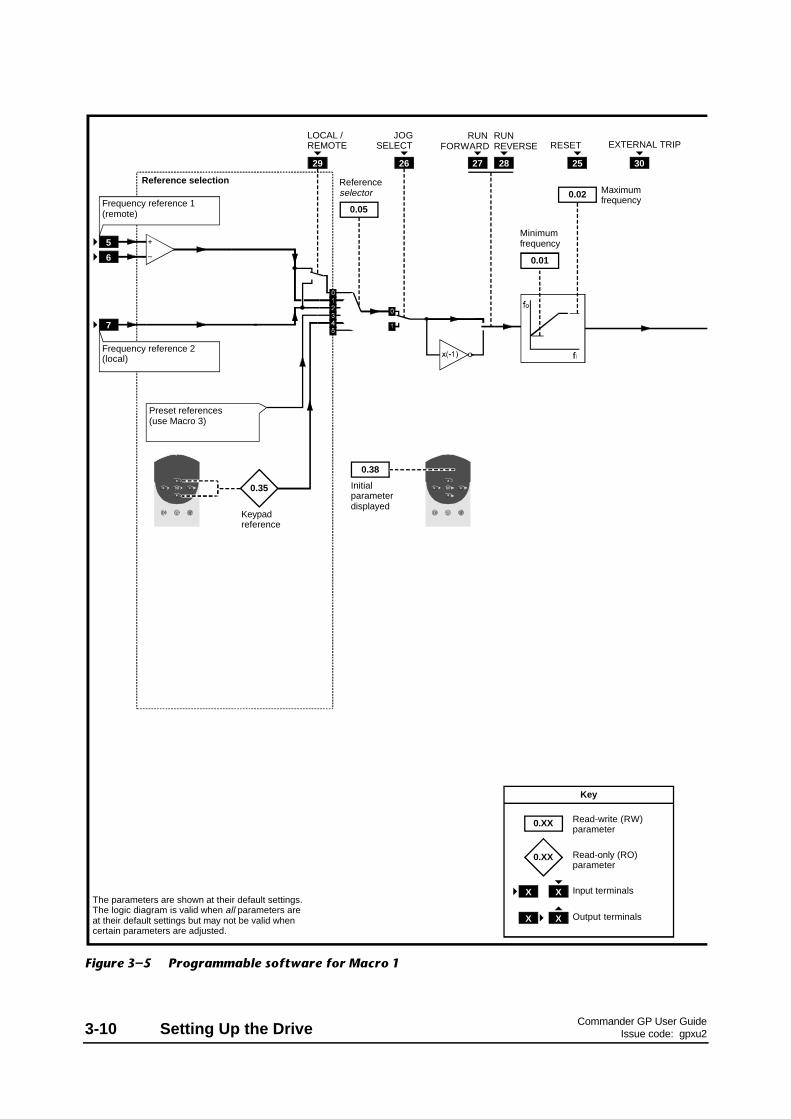
Reference selection
Frequency reference 1 (remote)
Frequency reference 2 (local)
Keypad reference
Preset references (use Macro 3)
JOG SELECT
RUN FORWARD
RUN REVERSE RESET
The parameters are shown at their default settings.The logic diagram is valid when all parameters are at their default settings but may not be valid when certain parameters are adjusted.
5
6
7
0.35
0.05
Referenceselector
29
LOCAL / REMOTE
26 27 28
Minimum frequency
Maximum frequency
0.01
0.02
Initial parameterdisplayed
0.38
25 30
EXTERNAL TRIP
0.XX
0.XX
X X
X X
Key
Read-write (RW) parameter
Read-only (RO) parameter
Input terminals
Output terminals
Figure 3–5 Programmable software for Macro 1

Commander GP User GuideIssue code: gpxu2 Setting Up the Drive 3-11
Ramps
Acceleration rate
Deceleration rate
SPEED TORQUE
Motor control
Current limit
Synchronize to a spinning motor
0.39
0.03
0.04
0.06
No. of polesPower factorRated voltageRated speedRated currentRated frequency
PWM switching frequency
0.41
0.42 ~ 0.47
Motor parameters
Power stage
9 10 24
AT SPEED
Voltage mode selector
Dynamic V/f select
0.07
Boost voltage
0.08
0.09
Motor-voltage control
Estimated motor speed
0.10
0.31 Macro number
0.32 Serial comms. mode
0.33 Drive rated current
0.34 User security code
0.36 Serial comms. baud rate
0.37 Serial comms. address
0.40 Autotune
0.48 Drive software build number
0.49 Security status
0.50 Software version number
Other parameters

Commander GP User GuideIssue code: gpxu23-12 Setting Up the Drive
Pr Function Uservalue
0.00 Configuration and saving
0.01 Minimum frequency
0.02 Maximum frequency
0.03 Acceleration rate
0.04 Deceleration rate
0.05 Reference selector
0.06 Current limit
0.07 Voltage mode selector
0.08 Boost voltage
0.09 Dynamic V/f select
0.10 Estimated motor speed [M]
0.31 Macro number [M]
0.32 Serial comms. mode
0.33 Drive rated current (FLC) [M]
0.34 User security code [M]
0.35 Keypad reference [M]
0.36 Serial comms. baud rate
0.37 Serial comms. address
0.38 Initial parameter displayed
0.39 Synchronize to a spinning motor
0.40 Autotune
0.41 PWM switching frequency selector
0.42 Motor – number of poles
0.43 Motor – power factor
0.44 Motor – rated voltage
0.45 Motor – rated speed
0.46 Motor – rated current
0.47 Motor – rated frequency
0.48 Drive software build number [M]
0.49 Security status [M]
0.50 Drive software version [M]
[M] indicates the parameter is for monitoring only
For descriptions of these parameters, see Appendix D Menu0 Parameters.
List of parameters specific to Macro 1

Commander GP User GuideIssue code: gpxu2 Setting Up the Drive 3-13
Setting up and using Macro 1
The following may require attention in addition tothe settings made in Chapter 2.
Reference selection
Use 0.05 Reference selector to select the requiredfrequency source, as follows:
0.05 Source Terminal(s)
0 Analog input 1 or 2 which can beselected using the LOCAL/REMOTEcontact
5 and 6, or 7
1 Analog input 1 5, 6
2 Analog input 2 7
3 (Do not use)
4 Keypad control
5 (Do not use)
Frequency references
Keypad mode
The value of the keypad reference can be read bydisplaying the value of 0.35 Keypad reference.
Terminal mode
Frequency reference 1 (terminals 5, 6) is configuredfor 0 to 10V signal.
Frequency reference 2 (terminal 7) is configured for4 to 20mA signal. Loss of the current signal will betreated as zero reference.
Jog
To use jog, close the JOG SELECT contact(terminal 26) before closing the RUN FORWARDcontact (terminal 27) or RUN REVERSE contact(terminal 28).
Jog will occur at 1.5Hz. This value cannot be altered.

Commander GP User GuideIssue code: gpxu23-14 Setting Up the Drive
Use this free space for notes

Commander GP User GuideIssue code: gpxu2 Setting Up the Drive 3-15
3.5 Macro 2Motorized potentiometer
Features
Special features
The digital inputs are configured to acceptmomentary UP and DOWN contacts.
Selection can be made between motorizedpotentiometer operation and normal frequencycontrol. In both cases, analog input 1 remainsconfigured for an analog frequency reference signal(0 to 10V).
Motorized potentiometer is used by first closing theRUN FORWARD or RUN REVERSE contact asrequired, then closing the UP or DOWN contact toincrease or decrease the speed. When the UP andDOWN contacts are both open, the Drive maintainsconstant speed until the closed RUN contact isopened.
The output of the motorized potentiometer can bemonitored by reading the value of 0.26 Motorizedpot. output indicator, and the frequency by readingthe value of 0.11 Pre-ramp reference.
The motorized potentiometer is reset when theRESET contact connected to terminal 25 is closedmomentarily. (This also resets the Drive.)
Selection can be made for the motorizedpotentiometer to return to the previous set speed,or start at zero, after each power-up.
Standard features• Macro 2 operates in Terminal mode only• Digital control by RUN FORWARD and
RUN REVERSE contacts• Analog frequency input• Adjustment of minimum and maximum
frequencies• Adjustment of acceleration and deceleration
ramps• S-ramp• Skip frequencies• Selection of stopping modes• Selection of braking mode• Motor thermistor input• Negative logic for the digital inputs• SPEED and TORQUE analog outputs• External trip digital input• Drive RESET digital input
Signal connections for Macro 2
0V common
Analog frequency reference 1 (remote) 0 ~ 10V
SPEED
TORQUE
0V common
UP
RESET and MOT. POT. RESET
DOWN
RUN FORWARD
External trip
0V common
ANALOG I/P
MOT. POT.
Status relayDrive healthy
RUN REVERSE
MOT. POT. ENABLE
Motor thermistor
Signal connector
Figure 3–6 Control signal and thermistorconnections for Macro 2
For electrical specifications, refer to Appendix CSignal Connections.

Commander GP User GuideIssue code: gpxu23-16 Setting Up the Drive
Reference selection
Frequency reference 1 (remote)
DOWN
RUN FORWARD
RUN REVERSE
RESET and MOT. POT. RESET
The parameters are shown at their default settings.The logic diagram is valid when all parameters are at their default settings but may not be valid when certain parameters are adjusted.
0.245
6
Analog input 1 mode selector
Motorized pot. output indicator
0.05
Referenceselector
29
MOTORIZED POT. ENABLE
27 28
Minimum frequency
Maximum frequency
0.01
0.02
0.20
0.21
0.22
0.23
Skip frequency 1
Skip band 1
Skip frequency 2
Skip band 2
Skip frequencies
Initial parameterdisplayed
0.38
25
24UP
30
EXTERNAL TRIP
Motorized pot. zero-start select
0.27
0.28
0.29
0.30
Motorized pot. bipolar select
Motorized pot. rate
Motorized pot. output scale factor
Motorized pot. reset indicator
0.26
26
0.25
0.XX
0.XX
X X
X X
Key
Read-write (RW) parameter
Read-only (RO) parameter
Input terminals
Output terminals
Figure 3–7 Programmable software for Macro 2

Commander GP User GuideIssue code: gpxu2 Setting Up the Drive 3-17
Ramps
Acceleration rate
Deceleration rate
Ramp mode selector
S-ramp enable
S-ramp da/dt limit
0.17 Status relay invert
0.31 Macro number
0.32 Serial comms. mode
0.33 Drive rated current
0.34 User security code
0.36 Serial comms. baud rate
0.37 Serial comms. address
0.40 Autotune
0.48 Drive software build number
0.49 Security status
0.50 Software version number
SPEED TORQUE
Motor control
Current limit
Synchronize to a spinning motor
Motor active-current
0.16
0.39
0.03
0.04
0.15
0.18
0.19
Pre-ramp reference
Post-ramp reference
0.11 0.12
S-ramp
0.06
Stop mode selector
No. of polesPower factorRated voltageRated speedRated currentRated frequency
PWM switching frequency
0.41
0.42 ~ 0.47
Motor parameters
0.13
Power stage
9 10
THERMISTOR
8
Voltage mode selector
Dynamic V/f select
0.07
Boost voltage
0.08
0.09
Motor-voltage control
Estimated motor speed
0.10
Other parameters

Commander GP User GuideIssue code: gpxu23-18 Setting Up the Drive
Pr Function Uservalue
0.00 Configuration and saving
0.01 Minimum frequency
0.02 Maximum frequency
0.03 Acceleration rate
0.04 Deceleration rate
0.05 Reference selector (do not adjust)
0.06 Current limit
0.07 Voltage mode selector
0.08 Boost voltage
0.09 Dynamic V/f select
0.10 Estimated motor speed [M]
[M] indicates the parameter is for monitoring only
For descriptions of these parameters, seeAppendix D Menu 0 Parameters.
List of parameters specific to Macro 2
Pr Function Uservalue
0.31 Macro number [M]
0.32 Serial comms. mode
0.33 Drive rated current (FLC) [M]
0.34 User security code [M]
0.35 Keypad reference [M]
0.36 Serial comms. baud rate
0.37 Serial comms. address
0.38 Initial parameter displayed
0.39 Synchronize to a spinning motor
0.40 Autotune
0.41 PWM switching frequency selector
0.42 Motor – number of poles
0.43 Motor – power factor
0.44 Motor – rated voltage
0.45 Motor – rated speed
0.46 Motor – rated current
0.47 Motor – rated frequency
0.48 Drive software build number [M]
0.49 Security status [M]
0.50 Drive software version [M]
Pr Function Uservalue
0.11 Pre-ramp reference [M]
0.12 Post-ramp reference [M]
0.13 Motor active-current [M]
0.14 Jog reference (not used)
0.15 Ramp mode selector
0.16 Stop mode selector
0.17 Status relay invert
0.18 S-ramp enable
0.19 S-ramp da/dt
0.20 Skip frequency 1
0.21 Skip band 1
0.22 Skip frequency 2
0.23 Skip band 2
0.24 Analog input 1 mode selector
0.25 Motorized pot. reset indicator [M]
0.26 Motorized pot. output indicator
0.27 Motorized pot. zero-start select
0.28 Motorized pot. bipolar select
0.29 Motorized pot. rate
0.30 Motorized pot. output scale factor

Commander GP User GuideIssue code: gpxu2 Setting Up the Drive 3-19
Setting up and using Macro 2
The following may require attention in addition tothe settings made in Chapter 2.
Motorized potentiometer settings
1. By default, the Drive operates in frequencycontrol. To disable this and enable themotorized potentiometer, close the MOT. POT.ENABLE contact (terminal 29).
2. If required, change the value of 0.29 Motorizedpot. rate to change the rate of increase anddecrease. Increasing the value reduces the rateof change of frequency.
Default value: 20 sRange: 0 ~ 250 s
3. If bipolar operation is required, set 0.28Motorized pot. bipolar select at 1.
4. By default, every time the Drive is powered-upand enabled, the frequency will return underramp control to the last setting of themotorized potentiometer. If the Drive isrequired to start at zero, set 0.27 Motorizedpot. zero-start select at 1.
5. To reset the motorized potentiometer,momentarily close the RESET contact. (Thisalso resets the Drive.)
6. If required, change the scaling of themotorized potentiometer output by adjusting0.30 Motorized pot. output scale factor.
7. If required, monitor the output value of thepotentiometer by reading 0.26 Motorized pot.output indicator.
Reference selection
For correct operation of this macro configuration,the setting of parameter of 0.05 Reference selectionshould be at 0.
Analog input modes
The analog input can be configured for thefollowing input signals:
0 ~ 20mA, 4 ~ 20mA or 0 ~ 10V
Refer to the following parameter in Appendix DMenu 0 Parameters for selecting the required mode:
Analoginput
Terminal(s) Parameter
1 5, 6 0.24Analog input 1 mode selector
Jog frequency
There is no need to adjust 0.14 Jog reference sincethe jog function cannot be used.
Stopping and braking modes
Refer to the following parameters in Appendix DMenu 0 Parameters:
Parameter Setting Function
0.150.15Ramp mode selector
Stnd.Ct (Standard controlled)Deceleration time isextended if the DC-busvoltage reaches itsmaximum permissiblevalue during braking.
0.160.16Stop mode selector
rP Ramp to stop then theDrive is disabled

Commander GP User GuideIssue code: gpxu23-20 Setting Up the Drive
Use this page for notes

Commander GP User GuideIssue code: gpxu2 Setting Up the Drive 3-21
3.6 Macro 3Preset frequencies
Features
Special features
Selection can be made between preset frequenciesand analog frequency control. In both cases, analoginput 1 remains configured for an analog frequencyreference signal (0 to 10V).
Up to four preset frequencies can be used; theirvalues must be programmed into individualparameters. Selection is made by external contactsoperating in binary logic.
Standard features• Macro 3 operates in Terminal mode only• Digital control by RUN FORWARD and
RUN REVERSE contacts• Analog frequency input• Adjustment of minimum and maximum
frequencies• Adjustment of acceleration and deceleration
ramps• Operation of the status relay can
be inverted• S-ramp• Skip frequencies• Selection of stopping modes• Selection of braking mode• Motor thermistor input• Negative logic for the digital inputs• SPEED and TORQUE analog outputs• External trip digital input• Drive RESET digital input
Signal connections for Macro 3
0V common
Analog frequency reference 1 (remote) 0 ~ 10V
SPEED
TORQUE
0V common
PRESET SELECT A
RESET
PRESET SELECT B
RUN FORWARD
External trip
0V common
ANALOG I/P
PRESET REFS.
Status relayDrive healthy
RUN REVERSE
PRESET ENABLE
Motor thermistor
Signal connector
Figure 3–8 Control signal and thermistorconnections for Macro 3
For electrical specifications, refer to Appendix CSignal Connections.

Commander GP User GuideIssue code: gpxu23-22 Setting Up the Drive
Reference selection
Frequency reference 1 (remote)
PRESET SELECT B
RUN FORWARD
RUN REVERSE RESET
The parameters are shown at their default settings.The logic diagram is valid when all parameters are at their default settings but may not be valid when certain parameters are adjusted.
0.245
6
0.25
Analog input 1 mode selector
0.05
Referenceselector
29
PRESET ENABLE
27 28
Minimum frequency
Maximum frequency
0.01
0.02
0.20
0.21
0.22
0.23
Skip frequency 1
Skip band 1
Skip frequency 2
Skip band 2
Skip frequencies
Initial parameterdisplayed
0.38
25
24PRESET
SELECT A
30
EXTERNAL TRIP
Preset reference 2
0.26
0.27
0.28
Preset reference 3
Preset reference 4
Preset reference 1
26
0.XX
0.XX
X X
X X
Key
Read-write (RW) parameter
Read-only (RO) parameter
Input terminals
Output terminals
A
0011
B
0101
Preset frequency
1234
Figure 3–9 Programmable software for Macro 3

Commander GP User GuideIssue code: gpxu2 Setting Up the Drive 3-23
Ramps
Acceleration rate
Deceleration rate
Ramp mode selector
S-ramp enable
S-ramp da/dt limit
0.17 Status relay invert
0.31 Macro number
0.32 Serial comms. mode
0.33 Drive rated current
0.34 User security code
0.36 Serial comms. baud rate
0.37 Serial comms. address
0.40 Autotune
0.48 Drive software build number
0.49 Security status
0.50 Software version number
SPEED TORQUE
Motor control
Current limit
Synchronize to a spinning motor
Motor active-current
0.16
0.39
0.03
0.04
0.15
0.18
0.19
Pre-ramp reference
Post-ramp reference
0.11 0.12
S-ramp
0.06
Stop mode selector
No. of polesPower factorRated voltageRated speedRated currentRated frequency
PWM switching frequency
0.41
0.42 ~ 0.47
Motor parameters
0.13
Power stage
9 10
THERMISTOR
8
Voltage mode selector
Dynamic V/f select
0.07
Boost voltage
0.08
0.09
Motor-voltage control
Estimated motor speed
0.10
Other parameters

Commander GP User GuideIssue code: gpxu23-24 Setting Up the Drive
Pr Function Uservalue
0.00 Configuration and saving
0.01 Minimum frequency
0.02 Maximum frequency
0.03 Acceleration rate
0.04 Deceleration rate
0.05 Reference selector (do not adjust)
0.06 Current limit
0.07 Voltage mode selector
0.08 Boost voltage
0.09 Dynamic V/f select
0.10 Estimated motor speed [M]
[M] indicates the parameter is for monitoring only
For descriptions of these parameters, seeAppendix D Menu 0 Parameters.
List of parameters specific to Macro 3
Pr Function Uservalue
0.31 Macro number [M]
0.32 Serial comms. mode
0.33 Drive rated current (FLC) [M]
0.34 User security code [M]
0.35 Keypad reference [M]
0.36 Serial comms. baud rate
0.37 Serial comms. address
0.38 Initial parameter displayed
0.39 Synchronize to a spinning motor
0.40 Autotune
0.41 PWM switching frequency selector
0.42 Motor – number of poles
0.43 Motor – power factor
0.44 Motor – rated voltage
0.45 Motor – rated speed
0.46 Motor – rated current
0.47 Motor – rated frequency
0.48 Drive software build number [M]
0.49 Security status [M]
0.50 Drive software version [M]
Pr Function Uservalue
0.11 Pre-ramp reference [M]
0.12 Post-ramp reference [M]
0.13 Motor active-current [M]
0.14 Jog reference (not used)
0.15 Ramp mode selector
0.16 Stop mode selector
0.17 Status relay invert
0.18 S-ramp enable
0.19 S-ramp da/dt
0.20 Skip frequency 1
0.21 Skip band 1
0.22 Skip frequency 2
0.23 Skip band 2
0.24 Analog input 1 mode selector
0.25 Preset reference 1
0.26 Preset reference 2
0.27 Preset reference 3
0.28 Preset reference 4
0.29 (Not used)
0.30 (Not used)

Commander GP User GuideIssue code: gpxu2 Setting Up the Drive 3-25
Setting up and using Macro 3
The following may require attention in addition tothe settings made in Chapter 2.
Preset references
1. By default, the Drive operates in frequencycontrol. To disable this and enable the presetreferences, close the PRESET ENABLE contact(terminal 29).
2. Enter the required values in the followingparameters:
0.25 Preset frequency 1
0.26 Preset frequency 2
0.27 Preset frequency 3
0.28 Preset frequency 4
Default value: 0Range: ±1000 Hz
3. Select the required preset reference as follows:
Presetreference
PRESET SELECT A(terminal 24)
PRESET SELECT B(terminal 26)
1 Open Open
2 Open Closed
3 Closed Open
4 Closed Closed
Reference selection
For correct operation of this macro configuration,the setting of parameter of 0.05 Reference selectionshould be at 0.
Analog input modes
The analog input can be configured for thefollowing input signals:
0 ~ 20mA, 4 ~ 20mA or 0 ~ 10V
Refer to the following parameter in Appendix DMenu 0 Parameters for selecting the required mode:
Analoginput
Terminal(s) Parameter
1 5, 6 0.24Analog input 1 mode selector
Jog frequency
There is no need to adjust 0.14 Jog reference sincethe jog function cannot be used.
Stopping and braking modes
Refer to the following parameters in Appendix DMenu 0 Parameters:
Parameter Setting Function
0.150.15Ramp mode selector
Stnd.Ct (Standard controlled)Deceleration time isextended if the DC-busvoltage reaches itsmaximum permissiblevalue during braking.
0.160.16Stop mode selector
rP Ramp to stop then theDrive is disabled

Commander GP User GuideIssue code: gpxu23-26 Setting Up the Drive
Use this free space for notes

Commander GP User GuideIssue code: gpxu2 Setting Up the Drive 3-27
3.7 Macro 4Torque control
Features
Specific features
Selection can be made between torque control andfrequency control.
When frequency control is selected, the Drive willrun at the frequency demand irrespective of load solong as the maximum permissible output current ofthe Drive is not reached. The frequency referencemust be applied to analog input 2.
When torque control is selected, analog input 1 isconfigured for an analog torque reference. Themaximum frequency is limited to the value of0.02 Maximum frequency. Analog input 2 is not used.
Both inputs accept 0 to 10V.
Torque slaving
Macro 4 can be used in applications where two ormore motors are mechanically linked and must sharethe torque load in a controlled way.
Standard features• Macro 4 operates in Terminal mode only• Digital control by RUN FORWARD and
RUN REVERSE contacts• Analog torque and frequency inputs• Adjustment of maximum frequencies• Adjustment of acceleration and deceleration
ramps• Operation of the status relay can
be inverted• Selection of braking mode• Motor thermistor input• Negative logic for the digital inputs• SPEED and TORQUE analog outputs• AT MINIMUM SPEED digital output• AT SPEED digital output• External trip digital input• Drive RESET digital input
Signal connections for Macro 4
Status relayDrive healthy
Analog torque reference 1 (0 ~ 10V)
Motor thermistor
SPEED
TORQUE
0V common
AT SPEED
RESET
AT MIN. SPEED
RUN FORWARD
RUN REVERSE
TORQUE ENABLE
External trip
0V common
0V common
FREQUENCY CONTROL
TORQUE CONTROL
0V common
Signal connector
Analog frequency reference 1 (0 ~ 10V)
Figure 3–10 Control signal and thermistorconnections for Macro 4
For electrical specifications, refer to Appendix CSignal Connections.

Commander GP User GuideIssue code: gpxu23-28 Setting Up the Drive
Reference selection
Analog torque reference
RUN FORWARD
RUN REVERSE RESET
The parameters are shown at their default settings.The logic diagram is valid when all parameters are at their default settings but may not be valid when certain parameters are adjusted.
0.245
6
Analog input 1 mode selector
0.05
Reference selector
27 28
Minimum frequency
Frequency over-ride
0.01
0.02
0.20
0.21
0.22
0.23
Skip frequency 1
Skip band 1
Skip frequency 2
Skip band 2
Skip frequencies
Initial parameterdisplayed
0.38
25 30
EXTERNAL TRIP
Analog input 10.25
7 0.26
Analog input 2 mode selector
Frequency control: Frequency reference
Torque control:(Not used)
Analog input 1 scaling
0.29
0.30
Analog input 2 scaling
0.XX
0.XX
X X
X X
Key
Read-write (RW) parameter
Read-only (RO) parameter
Input terminals
Output terminals
0.27Analog input 2
Figure 3–11 Programmable software for Macro 4

Commander GP User GuideIssue code: gpxu2 Setting Up the Drive 3-29
Ramps
Acceleration rate
Deceleration rate
Ramp mode selector
S-ramp enable
S-ramp da/dt limit
0.17 Status relay invert
0.28 Over-speed threshold
0.31 Macro number
0.32 Serial comms. mode
0.33 Drive rated current
0.34 User security code
0.36 Serial comms. baud rate
0.37 Serial comms. address
0.40 Autotune
0.48 Drive software build number
0.49 Security status
0.50 Software version number
SPEED TORQUE
Motor control
Current limit
Synchronize to a spinning motor
Motor active-current
29
TORQUE ENABLE
0.16
0.39
0.03
0.04
0.15
0.18
0.19
Pre-ramp reference
Post-ramp reference0.11 0.12
S-ramp
0.06
Stop mode selector
No. of polesPower factorRated voltageRated speedRated currentRated frequency
PWM switching frequency
0.41
0.42 ~ 0.47
Motor parameters
0.13
Power stage
THERMISTOR
8
Voltage mode selector
Dynamic V/f select
0.07
Boost voltage
0.08
0.09
Motor-voltage control
Estimated motor speed
0.10
Other parameters
9 10 24
AT SPEED
26
AT MIN. SPEED

Commander GP User GuideIssue code: gpxu23-30 Setting Up the Drive
Pr Function Uservalue
0.00 Configuration and saving
0.01 Minimum frequency
0.02 Maximum frequency
0.03 Acceleration rate
0.04 Deceleration rate
0.05 Reference selector (do not adjust)
0.06 Current limit
0.07 Voltage mode selector
0.08 Boost voltage
0.09 Dynamic V/f select
0.10 Estimated motor speed [M]
[M] indicates the parameter is for monitoring only
For descriptions of these parameters, seeAppendix D Menu 0 Parameters.
List of parameters specific to Macro 4
Pr Function Uservalue
0.31 Macro number [M]
0.32 Serial comms. mode
0.33 Drive rated current (FLC) [M]
0.34 User security code [M]
0.35 Keypad reference [M]
0.36 Serial comms. baud rate
0.37 Serial comms. address
0.38 Initial parameter displayed
0.39 Synchronize to a spinning motor
0.40 Autotune
0.41 PWM switching frequency selector
0.42 Motor – number of poles
0.43 Motor – power factor
0.44 Motor – rated voltage
0.45 Motor – rated speed
0.46 Motor – rated current
0.47 Motor – rated frequency
0.48 Drive software build number [M]
0.49 Security status [M]
0.50 Drive software version [M]
Pr Function Uservalue
0.11 Pre-ramp reference [M]
0.12 Post-ramp reference [M]
0.13 Motor active-current [M]
0.14 Jog reference (not used)
0.15 Braking mode selector
0.16 Stop mode selector
0.17 Status relay invert
0.18 S-ramp enable
0.19 S-ramp da/dt
0.20 Skip frequency 1
0.21 Skip band 1
0.22 Skip frequency 2
0.23 Skip band 2
0.24 Analog input 1 mode selector
0.25 Analog input 1 (torque reference)
0.26 Analog input 2 mode selector
0.27 Analog input 2 (frequency reference)
0.28 Over-speed threshold
0.29 Analog input 1 scaling
0.30 Analog input 2 scaling

Commander GP User GuideIssue code: gpxu2 Setting Up the Drive 3-31
Setting up and using Macro 4
Torque control
1. By default, the Drive operates in frequencycontrol. To disable this and enable torquecontrol, close the TORQUE ENABLE contact(terminal 29).
2. Set 0.02 Frequency over-ride at the requiredvalue to limit the maximum speed of the motor.
3. Set the analog torque reference at therequired level.
4. If required, adjust 0.29 Analog input 1 scaling tochange the scaling of the torque referenceinput (see Torque slaving below).
5. If required, adjust 0.30 Analog input 2 scaling tochange the scaling of the frequency referenceinput.
6. Set 0.28 Over-speed threshold at the frequencythat the Drive is to trip for protecting thesystem.
Default value: ([0.02] x 1.2) Hz
Range: 0 ~ ([1.06] x 1.2) Hz
7. Monitor the torque reference by displayingparameter 0.25 Analog input 1.
Reference selection
For correct operation of this macro configuration,the setting of parameter 0.05 Reference selectionshould be at 0.
Jog frequency
There is no need to adjust 0.14 Jog reference sincethe jog function cannot be used.
Analog input modes
The analog inputs can be configured for thefollowing input signals:
0 ~ 20mA, 4 ~ 20mA or 0 ~ 10V
Refer to the following parameters in Appendix DMenu 0 Parameters for selecting the required mode:
Analoginput
Terminal(s) Parameter
1 5, 6 0.24Analog input 1 mode selector
2 7 0.26Analog input 2 mode selector
Torque slaving
1. Set up a master Drive in Macro 0 withfrequency control.
2. Set up slave Drive(s) in Macro 4.
3. Make connections between the Drives as shownin Figure 3–12.
Master Drive Slave Drive
Signal connector
(part)
Signal connector
(part)
Figure 3–12 Torque slaving connections
4. If the slave Drive(s) is to deliver a differenttorque from that of the master Drive, for(each) slave Drive, adjust 0.29 Analog input 1scaling accordingly.
Stopping and braking modes
Refer to the following parameters in Appendix DMenu 0 Parameters:
Parameter Setting Function
0.150.15Ramp mode selector
Stnd.Ct (Standard controlled)Deceleration time isextended if the DC-busvoltage reaches itsmaximum permissiblevalue during braking.
0.160.16Stop mode selector
rP Ramp to stop then theDrive is disabled

Commander GP User GuideIssue code: gpxu23-32 Setting Up the Drive
Use this free space for notes

Commander GP User GuideIssue code: gpxu2 Setting Up the Drive 3-33
3.8 Macro 5PID (set-point control)
Features
Specific features
PID control is used for applications where a processis required to be maintained at a set-point. Typicalapplications are as follows:
• Closed-loop tension-control processeswhere a dancer-arm is used
• Closed-loop pressure-control systems
Selection can be made between PID and analogfrequency control. When PID control is selected,the three analog inputs are configured as follows:
• Frequency reference to define the frequencydemand
• PID feedback from the feedback device• PID reference to define the set-point
The dynamic performance, scaling and range of thePID control can be adjusted.
Two preset references and an optional softwarePID-enable can be used.
Standard features• Macro 5 operates in Terminal mode only• Digital control by RUN FORWARD and
RUN REVERSE contacts• Analog frequency inputs• Adjustment of acceleration and deceleration
ramps• Negative logic for the digital inputs• SPEED and TORQUE analog outputs• AT SPEED digital output• External trip digital input• Drive RESET digital input
Signal connections for Macro 5
Status relayDrive healthy
Frequency reference 1 (0 ~ 10V)
PID feedback
TORQUE
0V common
PID reference (0 ~ 10V)
AT SPEED
RESET
RUN FORWARD
RUN REVERSE
PID ENABLE
External trip
0V common
0V common
PID CONTROL
FREQUENCY CONTROL
0V common
SPEED
Signal connector
Figure 3–13 Control signal connectionsfor Macro 5
For electrical specifications, refer to Appendix CSignal Connections.

Commander GP User GuideIssue code: gpxu23-34 Setting Up the Drive
Reference selection
Frequency reference
PID reference
RUN FORWARD
RUN REVERSE
Analog input 3
RESET
The parameters are shown at their default settings.The logic diagram is valid when all parameters are at their default settings but may not be valid when certain parameters are adjusted.
5
6
7 0.15
Analog input 2 mode selector
Analog input 1
0.05
Referenceselector
29
PID ENABLE
27 28
Minimum frequency
Maximum frequency
0.01
0.02
0.20
0.21
0.22
0.23
PID proportional gain
PID integral gain
PID derivative gain
PID output high limit
Initial parameterdisplayed
0.38
25 30
EXTERNAL TRIP
0.17
0.18
Analog input 2
8
PID feedback
PID
0.16
Analog input 3 mode selector
0.19
0.24
PID output low limit
0.25
PID output scale factor
0.28
0.14
Analog input 1 mode selector
Analog input 2 scaling
0.29Analog input 3 scaling
0.XX
0.XX
X X
X X
Key
Read-write (RW) parameter
Read-only (RO) parameter
Input terminals
Output terminals
Post-scaling PID reference
0.26
Post-scaling PID feedback
0.27
Figure 3–14 Programmable software for Macro 5
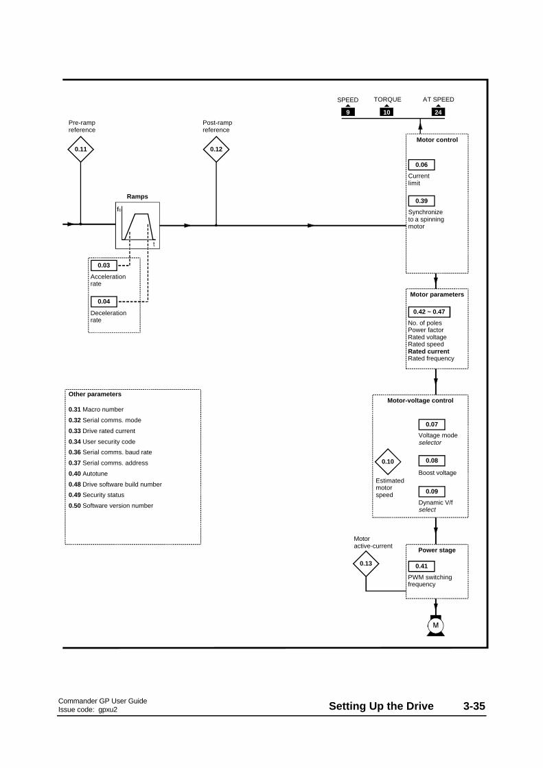
Commander GP User GuideIssue code: gpxu2 Setting Up the Drive 3-35
Ramps
Acceleration rate
Deceleration rate
SPEED TORQUE
Motor control
Current limit
Synchronize to a spinning motor
Motor active-current
0.39
0.03
0.04
Pre-ramp reference
Post-ramp reference
0.11 0.12
0.06
No. of polesPower factorRated voltageRated speedRated currentRated frequency
PWM switching frequency
0.41
0.42 ~ 0.47
Motor parameters
0.13
Power stage
9 10 24
AT SPEED
Voltage mode selector
Dynamic V/f select
0.07
Boost voltage
0.08
0.09
Motor-voltage control
Estimated motor speed
0.10
0.31 Macro number
0.32 Serial comms. mode
0.33 Drive rated current
0.34 User security code
0.36 Serial comms. baud rate
0.37 Serial comms. address
0.40 Autotune
0.48 Drive software build number
0.49 Security status
0.50 Software version number
Other parameters

Commander GP User GuideIssue code: gpxu23-36 Setting Up the Drive
Pr Function Uservalue
0.00 Configuration and saving
0.01 Minimum frequency
0.02 Maximum frequency
0.03 Acceleration rate
0.04 Deceleration rate
0.05 Reference selector (do not adjust)
0.06 Current limit
0.07 Voltage mode selector
0.08 Boost voltage
0.09 Dynamic V/f select
0.10 Estimated motor speed [M]
[M] indicates the parameter is for monitoring only
For descriptions of these parameters, seeAppendix D Menu 0 Parameters.
List of parameters specific to Macro 5
Pr Function Uservalue
0.31 Macro number [M]
0.32 Serial comms. mode
0.33 Drive rated current (FLC) [M]
0.34 User security code [M]
0.35 Keypad reference [M]
0.36 Serial comms. baud rate
0.37 Serial comms. address
0.38 Initial parameter displayed
0.39 Synchronize to a spinning motor
0.40 Autotune
0.41 PWM switching frequency selector
0.42 Motor – number of poles
0.43 Motor – power factor
0.44 Motor – rated voltage
0.45 Motor – rated speed
0.46 Motor – rated current
0.47 Motor – rated frequency
0.48 Drive software build number [M]
0.49 Security status [M]
0.50 Drive software version [M]
Pr Function Uservalue
0.11 Pre-ramp reference [M]
0.12 Post-ramp reference [M]
0.13 Motor active-current [M]
0.14 Analog input 1 (frequency reference)mode selector
0.15 Analog input 2 (PID reference) modeselector
0.16 Analog input 3 (PID feedback) modeselector
0.17 Analog input 1(frequency reference)
0.18 Analog input 2(PID reference)
0.19 Analog input 3(PID feedback)
0.20 PID proportional gain
0.21 PID integral gain
0.22 PID derivative gain
0.23 PID output high limit
0.24 PID output low limit
0.25 PID output scale factor
0.26 Post-scaling PID reference
0.27 Post-scaling PID feedback
0.28 Analog input 2 scaling
0.29 Analog input 3 scaling
0.30 (Not used)

Commander GP User GuideIssue code: gpxu2 Setting Up the Drive 3-37
Setting up and using Macro 5
Setting up PID control
1. By default, the Drive operates in frequencycontrol. To disable this and enable PID control,close the PID ENABLE contact (terminal 29).
2. Set the PID REFERENCE potentiometer(terminal 7) at the required set-point.
3. Set the FREQUENCY REFERENCE (terminals5, 6) for the required nominal motor (process)speed.
4. Connect the feedback device to terminal 8(PID FEEDBACK ).
5. The values of the analog signals can bemonitored by displaying the followingparameters:
0.17 Frequency reference
0.18 PID reference
0.19 PID feedback
0.26 Post-scaling PID reference
0.27 Post-scaling PID feedback
Adjusting the PID control range
In PID control, the PID reference and PID feedbackare each passed through a scaling stage, and theerror resulting from differences between thesereferences is passed through a limiter and thenthrough a final scaling stage.
The limiter is used for applying minimum andmaximum limits to the PID error. The minimumerror can be a negative value.
The final scaling stage is used for adjusting thedegree of change to the frequency reference.
After these two stages, the error is added to thefrequency reference.
1. The default scaling for analog inputs 2 and 3is 1. If required, adjust the followingparameters to alter the scaling:
0.28 Analog input 2 scaling (PID reference)
0.29 Analog input 3 scaling (PID feedback)
2. To limit the maximum value of PID error, set0.23 PID high limit at the required value.
Default value: 100 %Range: 0 ~ 100 %
3. To define the minimum value of PID error, set0.24 PID low limit at the required value.
Default value: –100 %Range: ±100 %
4. To define the degree of control on thefrequency reference, set 0.25 PID output scalefactor at the required value.
Default value: 1Range: 0 ~ 4.000
Adjusting the PID gain settings
The following parameters are used:
0.20 PID proportional gainDefault value: 1Range: 0 ~ 4.000
0.21 PID integral gainDefault value: 0.5Range: 0 ~ 4.000
0.22 PID derivative gainDefault value: 0Range: 0 ~ 4.000
Reference selection
For correct operation of this macro configuration,the setting of parameter of 0.05 Reference selectionshould be at 0.
Analog input modes
The analog inputs can be configured for thefollowing input signals:
0 ~ 20mA, 4 ~ 20mA or 0 ~ 10V
Refer to the following parameters in Appendix DMenu 0 Parameters for selecting the required mode:
Analoginput
Terminal(s) Parameter
1 5, 6 0.14Analog input 1 mode selector
2 7 0.15Analog input 2 mode selector
3 8 0.16Analog input 3 mode selector

Commander GP User GuideIssue code: gpxu23-38 Setting Up the Drive
3.9 Macro 6Axis-limit control
Features
Specific features
Axis-limit control is used for applications whichrequire the process to be automatically stoppedwhen a position limit has been reached.
Speed can be controlled in both directions in eitherof two ways, as follows:
• Bipolar frequency reference signal and useof a RUN FORWARD contact (bipolarcontrol)
• Unipolar frequency reference signal and useof RUN FORWARD and RUN REVERSEcontacts (unipolar control)
Selection can be made between the followingfrequency reference inputs:
Local unipolar input (0 ~ 10V)Remote differential input which can be usedas follows:• Single-ended unipolar input (0 ~ 10V)• Single-ended bipolar input (±10V)• Bipolar or unipolar differential input (±10V
on each line)
Travel in each direction is halted by use of a LIMITdigital input. By default, these inputs requirenormally-open contacts but can be configured fornormally-closed contacts.
To run the Drive, the appropriate RUN contact mustbe closed. When the related LIMIT contact changesstate to mark the axis limit, the Drive decelerates tozero speed at a rate set by the user. In order tochange direction, it is necessary to perform either ofthe following, as appropriate:
• Bipolar control: Reverse the polarity of thefrequency reference
• Unipolar control: Open the RUN switch, andthen close the RUN switch for the oppositedirection
The Drive is operated under frequency control.
Selection can be made to apply torque to the motorat zero speed, or to allow the motor to rotatefreely.
Standard features• Macro 6 operates in Terminal mode only• Adjustment of minimum and maximum
frequencies• Adjustment of acceleration and
deceleration ramps• Selection of stopping modes• Motor thermistor input• SPEED and TORQUE analog outputs• AT SPEED digital output• External trip digital input• Drive RESET digital input

Commander GP User GuideIssue code: gpxu2 Setting Up the Drive 3-39
Signal connections for Macro 6
Analog frequency/speed reference 1(remote) 0 ~ 10V
SPEED
TORQUE
0V common
AT SPEED
RESET
LIMIT FORWARD
RUN FORWARD
External trip
0V common
Status relayDrive healthy
RUN REVERSE
LIMIT REVERSE
Motor thermistor
Signal connector
0V commonAnalog frequency/speed reference 2 (local) 0 ~ 10V
Figure 3–14 Control signal and thermistorconnections for Macro 6 whenused in unipolar control
Analog frequency/speed reference±10V
SPEED
TORQUE
0V common
Status relayDrive healthy
Motor thermistor
Signal connector
0V common
AT SPEED
RESET
LIMIT FORWARD
RUN
External trip
0V common
LIMIT REVERSE
+10V
−10V
0V
Figure 3–15 Control signal and thermistorconnections for Macro 6 whenused in bipolar control (typicalfrequency referenceconnections)
For electrical specifications, refer to Appendix CSignal Connections.

Commander GP User GuideIssue code: gpxu23-40 Setting Up the Drive
Reference selection
Frequency reference 1 (remote)
Frequency reference 2 (local)
LIMIT FORWARD
RUN (FORWARD)
RUN REVERSE
The parameters are shown at their default settings.The logic diagram is valid when all parameters are at their default settings but may not be valid when certain parameters are adjusted.
5
6
7
0.05
Referenceselector
29
LIMIT REVERSE
2627 28
Minimum frequency
clamp0.01
0.02
0.21
Limit forward invert
Power up parameter display setting
0.38
0.XX
0.XX
X X
X X
Key
Read-write (RW) parameter
Read-only (RO) parameter
Input terminals
Output terminals
Maximum frequency
clamp
Limit forward indicator
0.14
Run forward indicator
0.15 0.170.16 0.22
Run reverse indicator
Limit reverse indicator
Limit reverse invert
Forward frequency reference
Frequency reference
Direction control
Bi-directional frequency reference
Reverse frequency reference
RUN enabledRUN disabled (at limit)
0 =1 =
Figure 3–16 Programmable software for Macro 6

Commander GP User GuideIssue code: gpxu2 Setting Up the Drive 3-41
Ramps
Acceleration rate
OL> Deceleration rate
RESET FREQUENCY TORQUE
Motor control
Current limit
Synchronize to a spinning motor
Motor active-current
0.18
0.39
0.03
0.20
Pre-ramp reference
Post-ramp reference
0.11 0.12 0.06
Stop mode selector
No. of polesPower factorRated voltageRated speedRated currentRated frequency
PWM switching frequency
0.41
0.42 ~ 0.47
Motor parameters
0.13
Power stage
25 9 10 24
AT SPEEDTHERMISTOR
830
EXTERNAL TRIP
Voltage mode selector
Dynamic V/f select
0.07
Boost voltage
0.08
0.09
Motor-voltage control
Estimated motor speed
0.10
0.31 Macro number
0.32 Serial comms. mode
0.33 Drive rated current
0.34 User security code
0.36 Serial comms. baud rate
0.37 Serial comms. address
0.40 Autotune
0.48 Drive operating mode selector
0.49 Security status
0.50 Software version number
Other parameters
0.19
Hold zero speed
CL> Deceleration rate
0.04

Commander GP User GuideIssue code: gpxu23-42 Setting Up the Drive
Pr Function Uservalue
0.00 Configuration and saving
0.01 Minimum frequency clamp
0.02 Maximum frequency clamp
0.03 Acceleration rate
0.04 Deceleration rate
0.05 Reference selector (limited settings)
0.06 Current limit
0.07 Voltage mode selector
0.08 Boost voltage
0.09 Dynamic V/f select
0.10 Estimated motor speed [M]
[M] indicates the parameter is for monitoring only
For descriptions of these parameters, seeAppendix D Menu 0 Parameters.
List of parameters specific to Macro 6
Pr Function Uservalue
0.11 Pre-ramp reference [M]
0.12 Post-ramp reference [M]
0.13 Motor active-current [M]
0.14 Limit forward indicator [M]
0.15 Run forward indicator [M]
0.16 Run reverse indicator [M]
0.17 Limit reverse indicator [M]
0.18 Stop mode selector
0.19 Hold zero speed enable
0.20 Limit deceleration rate
0.21 Limit forward invert
0.22 Limit reverse invert
0.23 (Not used)
0.24 (Not used)
0.25 (Not used)
0.26 (Not used)
0.27 (Not used)
0.28 (Not used)
0.29 (Not used)
0.30 (Not used)
Pr Function Uservalue
0.31 Macro number [M]
0.32 Serial comms. mode
0.33 Drive rated current (FLC) [M]
0.34 User security code [M]
0.35 Keypad reference [M]
0.36 Serial comms. baud rate
0.37 Serial comms. address
0.38 Power up parameter display select
0.39 Synchronize to a spinning motor
0.40 Autotune
0.41 PWM switching frequency selector
0.42 Motor – number of poles
0.43 Motor – power factor
0.44 Motor – rated voltage
0.45 Motor – rated full load RPM
0.46 Motor – rated current
0.47 Motor – rated frequency
0.48 Drive operating mode selector
0.49 Security status [M]
0.50 Drive software version [M]

Commander GP User GuideIssue code: gpxu2 Setting Up the Drive 3-43
Setting up and using Macro 6
The following may require attention in addition tothe settings made in Chapter 2.
Frequency control
When Macro 6 is selected, the Drive always operatesin axis-limit control; unlike Macros 2 to 5, no digitalinput exists to allow switching to and from normalfrequency control.
Operation in bipolar or unipolar frequency control isdependent only on the signal connections made. When bipolar control is required, to preventconfusion do not connect a RUN REVERSE contact. No jog function exists.
Reference selection
Use 0.05 Reference selector to select the requiredfrequency reference source, as follows:
0.05 Source Terminal(s)
0 Analog input 1 (bipolar or unipolar) 5, 6
1 Analog input 1 (bipolar or unipolar) 5, 6
2 Analog input 2 (unipolar only) 7
3 (Do not use)
4 (Do not use)
5 (Do not use)
Analog input mode
The analog inputs are configured for 0 ~ 10V.
See the Commander Gp Advanced User Guide forselecting other modes.
Limit switch types
By default, the Drive requires normally-open limitswitches. When either or both limit switches are tobe normally-closed, set the following parametersat 1, as appropriate:
LIMIT FORWARD 0.21LIMIT REVERSE 0.22
Deceleration rates
Caution
Position the limit switchesto allow for the distancethat will be travelled duringdeceleration. This distancewill be increased if thedeceleration time isextended (see Braking mode).
The rate of deceleration to be applied when themotor is being stopped at the limit of travel can beadjusted separately from the normal decelerationrate, as follows:
Use 0.04 Deceleration rate for adjusting themaximum deceleration rate that is to apply whenany of the following occurs:
• The motor is stopped by removal of a RUNcommand
• The motor is stopped or slowed byreduction of the frequency reference
For setting the deceleration rate at the limit oftravel, use parameter 0.20 Limit deceleration rate.
Braking mode
The FASt ramp mode is applied. This givescontinuous deceleration under maximum brakingconditions (the ramp mode should not be changed). A braking resistor is normally required in order toprevent the DC-bus voltage from reaching the triplevel.
Stopping modes
Refer to parameter 0.18 Stop mode selector inAppendix D Menu 0 Parameters.
Hold zero speed
Refer to parameter 0.19 Hold zero speed enable inAppendix D Menu 0 Parameters.
The default setting is 0 (Free torotate).

Commander GP User GuideIssue code: gpxu23-44 Setting Up the Drive
Use this free space for notes

Commander GP User GuideIssue code: gpxu2 Setting Up the Drive 3-45
3.10 Macro 7Brake control
Features
Specific features
Brake control is used for controlling the applicationand release of a mechanical brake in hoist or craneapplications. The Drive issues a brake release signalwhen all of the following conditions are met:
• The Drive has not tripped (ie. healthy)• The output frequency of the Drive is
above 1Hz• Current above a user-defined threshold is
being supplied to the motor in order to holdor move the load
The brake release signal can be delayed by an amountthat is adjusted by the user. This delay is used toensure that only genuine conditions will cause thebrake to be released.
The Drive applies the brake, by removing the brakerelease signal, as the motor is stopping and motorcurrent falls below the threshold level.
The Drive is operated under frequency control;selection can be made between local and remotesources, as well as keypad control.
Standard features• Macro 7 can be operated in Terminal mode
(default) or Keypad mode• Digital control by RUN FORWARD, and
RUN REVERSE contacts• Analog frequency inputs• Adjustment of minimum and maximum
frequencies• Adjustment of acceleration and
deceleration ramps• Motor thermistor input• SPEED and TORQUE analog outputs• External trip digital input• Drive RESET digital input
Signal connections for Macro 7
0V common
Analog frequency reference 1 (remote) 0 ~ 10V
SPEED
TORQUE
0V common
BRAKE RELEASE
RESET
RUN FORWARD
External trip
0V common
REMOTE
LOCAL
RUN REVERSE
LOCAL / REMOTE
Signal connector
Analog frequency reference 2 (local) 0 ~ 10V
Motor thermistor
Figure 3–17 Control signal and thermistorconnections for Macro 7
The BRAKE RELEASE output must be connected asshown in Figure 3–17. Note that the actual BRAKERELEASE output appears on terminal 24 whichoperates as shown in the following table.
Terminal 24 BRAKE RELEASElogic state
Effect
Low 1 Release brake
High 0 Apply brake
For electrical specifications, refer to Appendix CSignal Connections.

Commander GP User GuideIssue code: gpxu23-46 Setting Up the Drive
Reference selection
Frequency reference 1 (remote)
Frequency reference 2 (local)
Keypad reference
Motor current magnitude
Preset references (see the Commander Gp Advanced User Guide)
RUN FORWARD
RUN REVERSE
Current threshold
RESET
5
6
7
0.35
0.14
0.05
Referenceselector
29
LOCAL / REMOTE
27 28
Minimum frequency clamp
0.01
0.02
0.19
Power up parameter display setting
0.38
25 24
BRAKE RELEASE
Maximum frequencyclamp
Drive healthy indicator
0.16
At zero speed indicator
0.17
Brake release indicator
0.18
Brake release delay
0.20
Current detected indicator
0.15
Figure 3–18 Programmable software for Macro 7

Commander GP User GuideIssue code: gpxu2 Setting Up the Drive 3-47
Ramps
Acceleration rate
Deceleration rate
FREQUENCY TORQUE
Motor control
Current limit
Synchronize to a spinning motor
Motor active-current
0.39
0.03
0.04
Pre-ramp reference
Post-ramp reference
0.11 0.12
0.06
No. of polesPower factorRated voltageRated speedRated currentRated frequency
PWM switching frequency
0.41
0.42 ~ 0.47
Motor parameters
0.13
Power stage
9 10
THERMISTOR
830
EXTERNAL TRIP
Voltage mode selector
Dynamic V/f select
0.07
Boost voltage
0.08
0.09
Motor-voltage control
Estimated motor speed
0.10
0.31 Macro number
0.32 Serial comms. mode
0.33 Drive rated current
0.34 User security code
0.36 Serial comms. baud rate
0.37 Serial comms. address
0.40 Autotune
0.48 Drive operating mode selector
0.49 Security status
0.50 Software version number
Other parameters
0.XX
0.XX
X X
X X
Key
Read-write (RW) parameter
Read-only (RO) parameter
Input terminals
Output terminals
The parameters are shown at their default settings.The logic diagram is valid when all parameters are at their default settings but may not be valid when certain parameters are adjusted.

Commander GP User GuideIssue code: gpxu23-48 Setting Up the Drive
Pr Function Uservalue
0.00 Configuration and saving
0.01 Minimum frequency clamp
0.02 Maximum frequency clamp
0.03 Acceleration rate
0.04 Deceleration rate
0.05 Reference selector (limited settings)
0.06 Current limit
0.07 Voltage mode selector
0.08 Boost voltage
0.09 Dynamic V/f select
0.10 Estimated motor speed [M]
[M] indicates the parameter is for monitoring only
For descriptions of these parameters, seeAppendix D Menu 0 Parameters.
List of parameters specific to Macro 7
Pr Function Uservalue
0.11 Pre-ramp reference [M]
0.12 Post-ramp reference [M]
0.13 Motor active-current [M]
0.14 Motor current magnitude [M]
0.15 Current detected indicator [M]
0.16 Drive healthy indicator [M]
0.17 At zero speed indicator [M]
0.18 Brake release indicator [M]
0.19 Current threshold
0.20 Brake release delay
0.21 (Not used)
0.22 (Not used)
0.23 (Not used)
0.24 (Not used)
0.25 (Not used)
0.26 (Not used)
0.27 (Not used)
0.28 (Not used)
0.29 (Not used)
0.30 (Not used)
Pr Function Uservalue
0.31 Macro number [M]
0.32 Serial comms. mode
0.33 Drive rated current (FLC) [M]
0.34 User security code [M]
0.35 Keypad reference [M]
0.36 Serial comms. baud rate
0.37 Serial comms. address
0.38 Power up parameter display select
0.39 Synchronize to a spinning motor
0.40 Autotune
0.41 PWM switching frequency selector
0.42 Motor – number of poles
0.43 Motor – power factor
0.44 Motor – rated voltage
0.45 Motor – rated full load RPM
0.46 Motor – rated current
0.47 Motor – rated frequency
0.48 Drive operating mode selector
0.49 Security status [M]
0.50 Drive software version [M]

Commander GP User GuideIssue code: gpxu2 Setting Up the Drive 3-49
Setting up and using Macro 7
The following may require attention in addition tothe settings made in Chapter 2.
Frequency control
When Macro 7 is selected, the Drive always operatesin brake control; unlike Macros 2 to 5, no digitalinput exists to allow switching to and from normalfrequency control.
The frequency of the motor is controlled in thesame way as in normal frequency control.
Reference selection
Use 0.05 Reference selector to select the requiredfrequency reference source, as follows:
0.05 Source Terminal(s)
0 Analog input 1 or 2 which can beselected using the LOCAL/REMOTEcontact
5 and 6, or 7
1 Analog input 1 5, 6
2 Analog input 2 7
3 Preset frequencies
4 Keypad control
5 ( Do not use)
Analog input mode
The analog inputs are configured for 0 ~ 10V.
See the Commander Gp Advanced User Guide forselecting other modes.
Brake-control settings
1. The default setting of 10% for parameter 0.19Current threshold is suitable for the majority ofapplications. If required, change the value tothe required percentage of Imax (see below). This value must ensure that adequate currentwill flow through the motor to control the loadwhen the brake is released.
IMAX = FLC x 150%
2. If required, change the setting of 0.20 Brakerelease delay to a suitable value (between 0 and25 seconds) that will ensure a brake releasesignal is not issued if the following occursimultaneously under transient conditions:
• 0.16 Drive healthy indicator changes stateto 1
• 0.17 At zero speed changes state to 0
Braking mode
The FASt ramp mode is applied. This givescontinuous deceleration under maximum brakingconditions (the ramp mode should not be changed). A braking resistor is normally required in order toprevent the DC-bus voltage from reaching the triplevel.
Stopping mode
The stopping mode is Ramp to a stop.

Commander GP User GuideIssue code: gpxu23-50 Setting Up the Drive
Use this free space for notes

Commander GP User GuideIssue code: gpxu2 Programming Instructions A-1
A ProgrammingInstructions
The instructions in this appendix take you step-by-step through learning how to use the display andkeypad, and alert you to avoid actions that couldcause confusion. It is in your interests to followthese instructions carefully.
The instructions can be used when the Drive isoperating in Keypad or Terminal mode. They coverthe basic procedure for accessing a numericalvariable parameter. Instructions for accessing othertypes of parameter, as well as for more advancedoperations, are given later in this appendix.
A.1 Electrical connections
Before following the instructions in this chapterensure the Drive has been connected in accordancewith the instructions in Chapter 2 Installing the Drive,in the Installation Guide or Chapter 2 Getting Startedin this User Guide.
When following the instructions in this appendix, Itis your responsibility to connect and disconnect theAC supply as required.
Warning
The terminal cover must befitted to the Drive before theAC supply is connected. If thecover needs to be removed, theAC supply must first bedisconnected for ten minutes.
Warning
The AC supply must beconnected to the Drive withappropriate fuses orprotection, as described in theInstallation Guide.
Warning
Adjustment of parametervalues must be performed onlyby suitably trained orexperienced personnel. Incorrect values could behazardous.
A.2 Preparation
1. Ensure that terminal 30 is connected toterminal 31 or that a contact connected tothese terminals is closed.
2. If these instructions are being followed when amacro other than Macro 1 is enabled, ensureterminal 8 is connected to terminal 11 or amotor thermistor is connected to theseterminals. These connections will allow theDrive to be operated.
3. Ensure that terminals 27 and 28 areopen-circuit, or that contacts connected tothese terminals are open. This will prevent amotor (if connected) from being driven.
4. Ensure that if a FREQUENCY potentiometer isconnected, it is set at minimum (wiper at0V common).
5. Connect the AC supply to the Drive.
6. The display is in Status mode and should indicateas follows:
If the lower display shows triP and the upper
display shows one of the following, check thecause and attend to the remedy:
Display Cause and remedy
th Motor thermistor not connected, or terminal 8not connected to terminal 11. Make thenecessary connections.
Et External trip signal received, or terminal 30 notconnected to terminal 31. Make the necessaryconnections.
rS Motor is not connected, one phase is notconnected or the motor is open-circuit.
Press to reset the Drive. The displayshould now show rdY
If the lower display still shows triP and anothercode is shown on the upper display, seeAppendix E Diagnostics.

Commander GP User GuideIssue code: gpxu2A-2 Programming Instructions
A.3 Status mode
The lower display shows rdY to indicate that theDrive is ready to drive a motor, as follows:
The upper display indicates the output frequency ofthe Drive or the motor speed. This is the value ofparameter 0.10. (The value of a different parametercould be shown if the Drive has been usedpreviously.)
A.4 Displaying the parameternumber in Status mode
When the display is in Status mode, the upperdisplay shows the value of parameter 0.10 (or of thelast parameter to be selected). The number of thisparameter can be shown on the lower displayinstead of the Drive status.
1. To show the parameter number, press:
or
2. To show the status, press: . The status isshown immediately.
A.5 Entering Parameter modeand returning toStatus mode
1. Momentarily press . The display entersParameter mode.
The lower display shows parameter number0.10. (A different parameter number could beshown if the Drive has been used previously.) The display appears as follows:
8 seconds
2. Do not press any keys. After eight seconds, thedisplay returns to Status mode. This showsthat the display always returns from Parametermode to Status mode when no keys are pressedwithin eight seconds.
You may repeat these two steps as many timesas required to obtain an understanding of theoperation.

Commander GP User GuideIssue code: gpxu2 Programming Instructions A-3
A.6 Selectinga parameter to access
If the display returns to Status mode during thecourse of selecting parameters (because no keyshave been pressed for eight seconds), to re-enterParameter mode, press:
1. Momentarily press . The display entersParameter mode.
Parameter number 0.10, or the number of thelast selected parameter, appears on the lowerdisplay. The value shown on the upper displayremains the same.
2. Within eight seconds, press
The parameter number decreases by one. Repeat this step until 0.06 is displayed.
Notice that the upper display changes to show
the value of the parameter that is selected.
Scrolling
1. Within eight seconds, press and hold down:
The parameter number continuously increases
(scrolls upward) until the highest numberedparameter in the menu is reached.
2. To start scrolling upward again from parameternumber 0.00, release then re-press:
3. Repeat steps 1 and 2 using
The parameter numbers will now decrease. Instep 2, when parameter 0.00 is reached,releasing and re-pressing the key will re-startdownward scrolling from the highest numberedparameter in the menu.
Quick selection of parameter 0.00
1. While the display is in Parameter mode, press atthe same time:
and
Parameter 0.00 is displayed.
2. Now select parameter number 0.06.

Commander GP User GuideIssue code: gpxu2A-4 Programming Instructions
A.7 Changing the value of aparameter
1. Within eight seconds of selecting parameter0.06, press:
The display enters Edit mode.
(If more than eight seconds have elapsed, thedisplay will have returned to Status mode. Inthis case, twice press:
On the first press, the display will re-enterParameter mode where parameter 0.06 willagain be displayed; on the second press, thedisplay will enter Edit mode.)
The upper display still shows the value of theparameter, but the least-significant digitflashes. (The value shown is the default valuefor 0.06; the value displayed may be different ifthe Drive has been used previously.)
Note that when the display is in Edit mode, it
will not return to Status mode after eightseconds. You can spend as much time asrequired changing the value of a parameter.
2. To decrease the value, momentarily press:
The value of the flashing digit decreases by one.
You can repeat this step as many times asrequired. The new value takes effectimmediately.
3. Press and hold down
The value scrolls downward. Release the keywhen the required value is reached.
To increase the value, press
4. When the required value is displayed, press:
5. The display returns to Parameter mode. If nokeys are pressed within eight seconds, thedisplay enters Status mode.
Making large changes in value quickly
So far, you have changed the value by incrementingor decrementing the least significant digit. Thespeed of change can be increased by selecting, thenscrolling either of the more significant digits, asfollows:
1. When the display is in Edit mode, momentarilypress:
When the key is released, the digit at the left of
the least significant digit flashes. Thisoperation can be repeated to select the mostsignificant digit of the display. If this digit isnot currently displayed, it can still be selected. When selected, a bar appears in its place.
You can then change the value of the newly
selected digit.

Commander GP User GuideIssue code: gpxu2 Programming Instructions A-5
Quick selection from least to mostsignificant digit To select the most significant digit when the
least significant digit is flashing, momentarilypress:
Quick selection from most toleast significant digit If the most significant digit of the display (not
just the displayed value) is flashing, to selectthe least significant digit, momentarily press:
Quick selection of theleast significant digit
Irrespective of the digit that is selected, to selectthe least significant digit, press at the same time:
and
Reaching the maximum or minimum value
A special condition arises when both the followingoccur:
• A digit other than the least significant digit(LSD) is being increased, and the maximumvalue is approached.
• The displayed LSD is not the same value asthe LSD of the maximum value. Forexample: if the displayed value is 126.4, andthe maximum value is 217.9, the displayedLSD of 4 differs from 9.
The special condition allows the value to be set ateither of the following:
• The highest permissible value that containsthe displayed LSD (eg. 4)
• The maximum value for the parameterUse the following procedure to see how theoperation works:1. Ensure the selected digit is not the LSD.
2. Press and hold down . When themaximum value is reached, the entire displayflashes the maximum value (eg. 217.9). Releasethe key within three flashes of the display. Thedisplay now shows the highest permissible value(eg. 216.4) that contains the displayed LSD.
3. Again press and hold down . When themaximum value is reached, the entire displayagain flashes the maximum value (eg. 217.9). Release the key after four flashes of the display. The display now shows the maximum value.
When setting the value at maximum in normaloperation, it is not necessary to follow step 2.
The same principles apply when reaching theminimum value.

Commander GP User GuideIssue code: gpxu2A-6 Programming Instructions
Setting the value at zero
1. Momentarily press at the same time:
and
Bench-testing? Return to default value If you have followed this procedure while
bench-testing the Drive, return the value to 150before returning the display toParameter mode.
A.8 Saving newparameter-values
Use the following procedure to save newparameter-values. The new values will then applyeach time the AC supply is subsequently applied tothe Drive. If new parameter-values are not saved,the previously saved (or default) values will applyeach time the AC supply is applied to the Drive.
1. Set parameter 0.00 at 1000.
2. Press . The display returns to Parametermode. Do not press any keys within eightseconds; the display then enters Status mode.
3. To reset the Drive when it is stopped, press:
To reset the Drive when it is running, press and
hold...
...then press:
Release both keys at the same time.
The new parameter-value(s) are now saved.
A.9 Flashing and non-flashingdigits
When the display is in Edit mode, the flashing of adigit indicates that the value of the digit can bechanged. If no digits flash, the parameter cannot beedited because it is read-only (or protected).
A.10 Negative values
When the value of a bipolar variable parameter isnegative, a minus sign appears at the left of thedisplayed value.
A.11 Changing the setting of abit parameter
When a bit parameter is selected and Edit modeentered, the display appears as shown below. bitappears at the left of the upper display. 0 or 1 isdisplayed at the right.
When 0 is displayed, press to select 1.
When 1 is displayed, press to select 0.

Commander GP User GuideIssue code: gpxu2 Programming Instructions A-7
A.12 Selecting a different option
Some variable parameters are used for selectingamong a number of options. These options can beshown as numbers (as 1 to 5 in parameter 0.05Reference selector) or as character strings (as Ur_S,etc, in parameter 0.07 Voltage mode selector).
1. To select a different option, press:
to ascend through the range of options
to descend through the range of options
When the first option is displayed, it isnecessary to ascend through the range in orderto select another option. When the last optionis displayed, it is necessary to descend throughthe range.
A.13 Restoring the Driveto a default configuration
Warning
Do not attempt to restore theDrive to a defaultconfiguration when the Drive isrunning.Restoring the Drive to adefault configuration enablesMacro 0 and returns allparameters to their defaultvalues including the motorparameters. (If any one of themacros 1 to 7 has been enabled,the Drive still reverts toMacro 0.)After restoring the Drive to adefault configuration, it will benecessary for the requiredparameter values to bere-entered before the Drive isnext run.
When the Drive is despatched from the factory, theparameters have default values, some of whichdepend on the AC supply frequency (European 50Hzor USA 60Hz). Consequently, the Drive has adefault configuration for each of these supplyfrequencies.
Use the following procedure:
1. Enter either of the following values inparameter 0.00:
1233 (Europe, 50Hz AC supply frequency)
1244 (USA, 60Hz AC supply frequency)
2. Press
The default values now take effect.
(The Drive is automatically restored to a defaultstate when the operating mode is changed.)
Saving the default values
If new parameter-values had previously been saved,these (not the default) values will apply when theAC supply is next connected to the Drive. If thedefault values are required instead, they must besaved in the same way as new values. Refer toSaving new parameter-values earlier in this chapter tosave the default values.
A.14 Summary of key operationChange the display mode
Parameter mode
or Select a parameter
and Select parameter 0.00
and Select Menu 0
Edit mode
or Change the value of a digitChange the setting of a bitparameterSelect a different option
and Select the value at 0
or Select a different digit
and Select the least significantdigit

Commander GP User GuideIssue code: gpxu2A-8 Programming Instructions

Commander GP User GuideIssue code: gpxu2 Security B-1
B Security
Note
Software versions V03.01.07 onward allowthe advanced parameters to be read andedited via. serial communicationsirrespective of the security state.
B.1 User-defined Security
The Drive is supplied without User Security havingbeen set-up. All parameters can be read and allread–write parameters can be edited.
User-defined Security operates only when it hasbeen set-up by the user. When locked, it preventsediting of all parameters except for parameter0.00.
The code number used to unlock User-definedSecurity is defined by the user. This givesprotection against unauthorized editing ofparameters. The code number can be read andedited only when User Security has been unlocked.
B.2 Setting-up User Security
Set-up User Security as follows:
1. Select parameter 0.34 User security code. Thedefault value 149 is displayed.
2. Change the value to the required User Securitynumber which must be within the range 0 to255. Do not use the default value 149.
3. When the display is returned to Parametermode, the displayed value reverts to 149. Thishides the new User Security number.
4. Follow the procedure in Saving newparameter-values in Appendix A ProgrammingInstructions.
User Security is now set-up.
B.3 Unlocking User Security
When User Security has been set-up and AC power isapplied to the Drive, User Security is automaticallylocked. No parameters can be edited except forparameter .00 in any menu.
Unlock User Security as follows:
1. Select parameter 0.00.
2. Set the value at the User Security code number.
All read–write parameters can now be edited.
B.4 Locking User Security
When User security has been set up, and theAC supply is removed and subsequently re-applied,User security becomes locked.
To lock User security without removing theAC supply, set parameter 0.00 at 2000.
B.5 Summary
Condition User Security
Locked Only parameter 0.00 can be edited; allother parameters can be read
Drive asdespatchedfrom thefactory
None
Setting upsecurity
Set 0.34 at 0 ~ 255 (but not 149); thedisplay reverts to 149 hiding the truevalue
Saving the codenumber
Occurs automatically at power-down
Locking Occurs automatically at power-down orwhen parameter 0.00 is set at 2000
Unlocking Set parameter 0.00 at the user securitycode; the display reverts to 0, hiding thetrue value
Changing thecode
Set 0.34 at the required value
Disablingsecurity
Set 0.34 at 149 (this value is alwaysdisplayed; just enter Edit mode andreturn to Parameter mode)
Restoring adefaultconfiguration
No change

Commander GP User GuideIssue code: gpxu2B-2 Security

Commander GP User GuideIssue code: gpxu2 Signal Connections C-1
C Signal Connections
Warning
The control circuits areisolated from the powercircuits in the Drive by basicinsulation only. The installermust ensure that the externalcontrol circuits are insulatedfrom human contact by at leastone layer of insulation ratedfor use at the AC supplyvoltage.
Warning
If the control circuits are to beconnected to other circuitsclassified as Safety Extra LowVoltage (SELV) (eg. to apersonal computer), anadditional isolating barriermust be included in order tomaintain the SELVclassification.
Logic levels of the digital inputs
Logic sense Logicstate
Voltage Action
Negative 0 ≥ 15V Open-circuit
1 ≤ 5V Connected to 0V
Positive 0 ≤ 5V Open-circuit
1 ≥ 15V Connected to +24V
For positive logic, the supply can be obtained fromterminal 22 +24V output.
Signal modes of the analog inputs
Signal Condition Parametersetting
0 ~ 10V VOLt
0 ~ 20 mA 0–20
20 ~ 0 mA 20–0
4 ~ 20 mA Trip on loss of signalcurrent
4–20.tr
20 ~ 4 mA Trip on loss of signalcurrent
20–4.tr
4 ~ 20 mA Minimum or low speedon loss of signal current
4–20.Lo
20 ~ 4 mA Minimum or low speedon loss of signal current
20–4.Lo
4 ~ 20 mA Previous speed on lossof signal current
4–20.Pr
20 ~ 4 mA Previous speed on lossof signal current
20–4.Pr
Descriptions of the controlsignal connections
The function and possibly the specification of someterminals change according to the macroconfiguration that is enabled. In these cases, thenumber of the associated macro configuration(s) isstated in italics before the function of the terminal. Where no indication is given, the function andspecification apply to all the macro configurations.
12
Status relay contact
Function Drive healthy
Contact voltage rating 240VACInstallation category 1
Contact current rating 5A resistive
Contact minimum currentrating
10mA
Contact condition Normally open
Isolation 1.5kV
Update period 8ms
3 0V common (analog)
Common connection for external analog devices.
4 +10V reference voltageFunction Supply for external analog
signal devices
Voltage tolerance ±1%
Maximum output current 10mA
Protection Current limit

Commander GP User GuideIssue code: gpxu2C-2 Signal Connections
Analog input 1
5 Non-inverting input
6 Inverting input
Macro Function0 1 2 3 5 6 7 Frequency reference 1 (remote)
4 Analog torque reference
Type of input Bipolar differential analog
(For single-ended use,connect terminal 6 toterminal 3)
Operating in voltage mode
Voltage range –10V ~ +10V
Absolute maximumvoltage range
–24V ~ +24V relative to 0V
±24V differential
Input resistance 100kΩ
Operating in current mode
Current ranges 0 ~ 20mA20mA ~ 04 ~ 20mA20 ~ 4mA
Absolute maximum current 50mA
Equivalent input resistance ≤200Ω at 20mA
Resolution 12-bit plus sign
Sampling period ≤2ms
7 Analog input 2
Macro Function0 1 6 7 Frequency reference 2 (local)
5 PID reference
Type of input Bipolar single-ended analog
Operating in voltage mode
Voltage range –10V ~ +10V
Absolute maximumvoltage range
±24V relative to 0V
Input resistance 100kΩ
Operating in current mode
Current ranges 0 ~ 20mA20mA ~ 04 ~ 20mA20 ~ 4mA
Absolute maximum current 50mA
Equivalent input resistance ≤200Ω at 20mA
When the Drive is used in torque control (Macro 4),terminal 7 is used for the analog torque reference.
8 Analog input 3
Macro Function0 2 3 4 6 7 Motor thermistor input*
1 No function
Internal pull-up voltage <5V
Trip threshold resistance 3 kΩ ±15%
Reset resistance 1.9 kΩ ±15%
Short-circuit detection R 51 Ω ±12%
Macro Function5 PID feedback
Type of input Bipolar single-ended analog
Operating in voltage mode
Voltage range –10V ~ +10V
Absolute maximumvoltage range
±24V relative to 0V
Input resistance 100kΩ
Operating in current mode
Current ranges 0 ~ 20mA20mA ~ 04 ~ 20mA20 ~ 4mA
Absolute maximum current 50mA
Equivalent input resistance ≤200Ω at 20mA
* When the Drive is used with Macro 0, 2, 3, 4, 6 or7 and a motor thermistor is not connected toterminal 8 (or terminal 15 on the 15-way D typeconnector), terminal 8 must be connected to 0V(terminal 3 or 11).
9 FREQUENCY output signal
10 TORQUE output signalType of output Single-ended analog voltage
Bipolar
Maximum output voltage –10V ~ +10V
Maximum output current 10mA peak
Load resistance 1kΩ minimum
Protection Short-circuit proof
Resolution 10-bit plus sign
Update period 8ms
11 0V common (analog)
Common connection for external analog devices.
21 0V common

Commander GP User GuideIssue code: gpxu2 Signal Connections C-3
22 +24V digital supplyVoltage tolerance ±10%
Nominal output current 200mA (total includingterminal 24)
Overload output current 240mA (total includingterminal 24)
Protection Current foldbackabove 240mA
Supply for external digital signal devices.
23 0V common (digital)
Common connection for external digital devices.
24 Macro Function
0 1 4 5 6
2
3
7
AT-SPEED outputUP inputPRESET SELECT A inputBRAKE RELEASE output
25 RESET input
26 Macro Function
0 1
2
3
4
6
JOG SELECT inputDOWN inputPRESET SELECT B inputAT MIN. SPEED outputLIMIT FORWARD input
27 RUN FORWARD input
28 RUN REVERSE input
29 Macro Function
0 1 7
2
3
4
5
6
LOCAL/REMOTE inputMOT. POT. ENABLE inputPRESET ENABLE inputTORQUE ENABLE inputPID ENABLE inputLIMIT REVERSE input
30 EXTERNAL TRIP input
Inputs
Input Negative-logic digital
Voltage range 0V ~ +24V
Absolute maximumvoltage range
–3V ~ +30V
Input current when0V applied
≥3.2mA
Negative-logic levels Inactive state(input open-circuit): > +15V
Active state: < +5V
Positive-logic levels Inactive state(input open-circuit): < +5V
Active state: > +15V
Outputs
Type of output Negative-logic digital(push-pull)
Voltage range 0V ~ +24V
Maximum output current 200mA (total includingterminal 22)
Overload output current 240mA (total includingterminal 22)
31 0V common (digital)
Common connection for external digital devices.

Commander GP User GuideIssue code: gpxu2C-4 Signal Connections

Commander GP User GuideIssue code: gpxu2 Menu 0 Parameters D-1
D Menu 0 Parameters
D.1 Introduction
Key
Type of parameterRO Read-only
RW Read–write
...selector Select from a number of settings
...select Select from two settings
...enable Make or allow a function to operate
...disable Stop or disallow a function fromoperating
...indicator The value can only be read
Limitations of useR The Drive must be reset for a new value to
take effect.
S The new parameter-value is saved when theAC supply is disconnected from the Drive.
P Protected parameter; the parameter cannotbe used as the destination parameter for aprogrammable input.
RangeBi Variable parameter having bipolar value
range.
Uni Variable parameter having unipolar valuerange.
Txt Variable parameter having text displayed. Anumber is stated alongside the setting; this isdisplayed on the system controller when theDrive is accessed by serial communications
Bit Bit parameter
FLC Full-load current (maximum continuousoutput current) (see Appendix C Data in theInstallation Guide)
Symbols
ð Default value
ô Range of values
[...] Indicates the value of the parameter
~ Indicates a range of values (in the case of bitparameters, ~ indicates or)
Categories of thefixed-function parameters
The parameters are arranged in the followingcategories:
0.00 Configuration and saving
0.01 ~ 0.02 Frequency limits
0.03 ~ 0.06 RampsFrequency reference selectionCurrent limit
0.07 ~ 0.09 Voltage boost
0.10 Speed indication
0.31 Macro-number indication
0.32 ~ 0.34 Miscellaneous
0.35 Keypad-reference monitoring
0.36 ~ 0.38 Serial communicationsParameter displayed at power-up
0.39 ~ 0.41 Spinning motorAutotunePWM switching frequency
0.42 ~ 0.47 Motor parameters
0.48 Drive software build number
0.49 ~ 0.50 Security and software information

Commander GP User GuideIssue code: gpxu2D-2 Menu 0 Parameters
D.2 Fixed-function parameterscommon to all macroconfigurations
Configuration
0.00 Macro selection,Configuration,Saving
RW Uni R
ô 0 ~ 2010 ð 0
Value Function
1000 Save new parameter-values
1233 Restore parameters to their default valuesfor 50Hz AC supply frequency (Europe)
1244 Restore parameters to their default valuesfor 60Hz AC supply frequency (USA)
2001 Macro 1Easy mode
2002 Macro 2Motorized potentiometer
2003 Macro 3Preset speeds
2004 Macro 4Torque control
2005 Macro 5PID control
2006 Macro 6Axis-limit control
2007 Macro 7Brake control
2009 Macro 0General purpose (USA default configuration)
2010 Macro 0General purpose (EUR default configuration)
Press after setting parameter 0.00 at therequired value.
Frequency limits
0.01 Minimum frequency
RW Uni
ô 0 ~ [0.02] ð 0 Hz
Set 0.01 at the required minimum output frequencyof the Drive for both directions of rotation. TheDrive runs at the minimum frequency when thefrequency reference is zero.
[0.01] is a nominal value; slip compensation maycause the actual frequency to be higher.
(When the Drive is jogging, [0.01] has no effect.)
0.02 Maximum frequency
Maximum frequency RW Uni
ô 0 ~ 1000.0 ð
ð
50 (EURO)60 (USA)
Hz
Set 0.02 at the required maximum outputfrequency for both directions of rotation. Thefrequency reference cannot cause the Drive to runat a frequency higher than [0.02].
[0.02] is a nominal value; slip compensation maycause the actual frequency to be higher.
(The Drive has additional over-speed protection.)
Caution
For operation at motor speedsgreater than twice base speed,contact the supplier of themotor.
Ramps,Frequency reference selection,Current limit
0.03 Acceleration rate
RW Uni
ô 0 ~ 3200.0 ð 5 s/100Hz
Set 0.03 at the required rate of acceleration. Notethat larger values produce lower acceleration. Therate applies in both directions of rotation.
0.03 does not apply to jog speed. See Menu 2 inthe Commander Gp Advanced User Guide for jogacceleration and deceleration rates.

Commander GP User GuideIssue code: gpxu2 Menu 0 Parameters D-3
0.04 Deceleration rate
RW Uni
ô 0 ~ 3200.0 ð 10 s/100Hz
Set 0.04 at the required rate of deceleration. Notethat larger values produce lower deceleration. Therate applies in both directions of rotation.
0.04 does not apply to jog speed. See Menu 2 inthe Commander Gp Advanced User Guide for jogacceleration and deceleration rates.
0.05 Reference selector
RW Uni
ô 0 ~ 5 ð (See below)
The default setting of 0.05 depends on the defaultconfiguration of the Drive, as follows:
EUR 0 Terminal mode
USA 4 Keypad mode
Note
Macros 2 to 5: Do not change the setting ofparameter 0.05.
Macro 6: Only settings 0, 1, 2 can be used.
Macro 7: Only settings 0, 1, 2, 4 can be used. For using setting 3, see the Commander GpAdvanced User Guide.
Use 0.05 to select the required frequencyreference, as follows:
Setting User-interface
mode
Function
0 Terminal Analog frequency referenceselected by LOCAL/REMOTEcontact
1 Terminal Analog frequencyreference 1 selected
2 Terminal Analog frequencyreference 2 selected
3 Terminal Preset frequency referencesselected (used withMacro 3)
4 Keypad Frequency controlled by thekeypad
5 (Not used)
0.06 Current limit
RW Uni
ô 0 ~ ≥150 ð 150 % IRATIO
IFLC
RATIO ==[ . ]0 46
0.06 limits the maximum output current of theDrive (and hence maximum motor torque) toprotect the Drive and motor from overload.
Set 0.06 at the required maximum torque as apercentage of the rated torque of the motor, asfollows:
[ . ] (%)0 06 100== ××T
TR
RATED
Where:
TR Required maximum torqueTRATED Motor rated torque
Alternatively, set 0.06 at the required maximumactive (torque-producing) current as a percentageof the rated active current of the motor, as follows:
[ . ] (%)0 06 100== ××I
IR
RATED
Where:
IR Required maximum active currentIRATED Motor rated active current
Refer to Setting the torque-producing current limit inChapter 3 Setting up the Drive.

Commander GP User GuideIssue code: gpxu2D-4 Menu 0 Parameters
Voltage boost
0.07 Voltage mode selector
Voltage mode selector RW Uni
ô (See below) ð Ur_I
Setting Function
Vector modes
Ur_S 0 Motor stator resistance is measured eachtime the Drive is started.
Ur_I 1 Motor stator resistance is measured atpower-up if the EXTERNAL TRIPEXTERNAL TRIP contact isclosed and no other trip condition exists.
Ur 2 Motor stator resistance is not measured(use this mode only after having usedUr_S or Ur_I to measure the statorresistance).
Fixed boost mode
Fd 3 Fixed voltage boost that can be manuallyadjusted by parameter 0.08 Boost voltage.
Use 0.07 to select fixed voltage boost, or Vectorcontrol of voltage boost. Fixed boost requires avalue to be set in 0.08 Boost voltage by the user. See Figure D–1. Fixed boost should be used when0.39 Synchronize to a spinning motor is set at 1.
Motor voltage
[0.08] Voltage boost
Frequency
Figure D–1 Effect of fixed voltage boost onthe voltage-to-frequencycharacteristic
Vector control causes the voltage boost to beautomatically regulated according to the load onthe motor.
Vector control requires the value of stator windingresistance to be stored in a parameter in the Drive. The three Vector modes allow the resistance to bemeasured under different circumstances.
0.08 Boost voltage
Boost voltage RW Uni
ô 0 ~ 25.0 ð 3.0 % x [0.44]
When 0.07 Voltage mode selector is set at Fd, set0.08 at the required value for the motor to runreliably at low speeds. See Figure D–1.
Excessive values of 0.08 can cause the motor to beoverheated.
0.09 Dynamic V/f select
Dynamic V/f select RW Bit
ô 0 ~ 1 ð 0
Set 0.09 at 0 when the V/f characteristic applied tothe motor is to be fixed. It is then based on therated voltage and frequency of the motor.
Set 0.09 at 1 when reduced power dissipation isrequired in the motor when it is lightly loaded. TheV/f characteristic is then variable resulting in themotor voltage being proportionally reduced forlower motor currents. Figure D–2 shows the changein V/f slope when the motor current is reduced.
Motor voltage
Frequency
AC supply voltage
IMOTOR
Figure D–2 Fixed and variableV/f characteristics

Commander GP User GuideIssue code: gpxu2 Menu 0 Parameters D-5
Speed indication
0.10 Estimated motor speed
Estimated motor speed RO Bi
ô ±6000 ð RPM
0.10 indicates the value of motor speed that isestimated from the following:
0.12 Post-ramp frequency reference0.42 Motor – no. of poles
The value of 0.10 is applied to the analog output onterminal 9 to indicate estimated speed.
Macro-number indication
0.31 Macro number
RO Uni
ô 0 ~ 7 ð
0.31 indicates the number of the macroconfiguration that is currently in operation.
Miscellaneous
0.32 Serial comms. mode
RW Txt R P
ô ANSI 2ANSI 4OUtPUtINPUt
ð ANSI 4
Use 0.32 to select the required serialcommunications mode as follows:
ANSI 2 ANSI protocol, two-wire
ANSI 4 ANSI protocol, four-wire
0.33 Drive rated current (FLC)
RO Uni P
ô 2.10 ~ 202 ð A
0.34 User security code
RW Uni S P
ô 0 ~ 255 ð 149
Use 0.34 to set up a User Security code. Irrespective of the code number entered in 0.34, italways indicates the default value 149. When 0.34is actually set at 149, no User Security is applied.
See Setting-up User Security in Appendix B Security.
Keypad-reference monitoring
0.35 Keypad reference
RO Bi S P
ô ± [0.02] ð Hz
0.35 indicates the value of the frequency referencewhen the Drive is operating in Keypad mode. Thereference is then controlled by the following controlkeys (when the display is in Status mode):
The value is automatically saved when the Drive ispowered-down. At the next power-up, the Driveramps up to the frequency that applied before thepower-down.
Serial communications,Parameter displayed after power-up
0.36 Serial comms. baud rate
RW Txt P
ô 4800 (0)9600 (1)
19200 (2)2400 (3)
ð 4800(0)
baud
Use 0.36 to select the required baud rate for serialcommunications when a Basic serial communicationslarge option module is fitted in the Drive.
0.37 Serial comms. address
RW Uni P
ô 0.0 ~ 9.9 ð 1.1 Group.Unit
Use 0.37 to select the required address for serialcommunications when a Basic serial communicationslarge option module is fitted in the Drive.
Do not enter an address that contains a zero, sincethis is used when addressing a group of Drives.

Commander GP User GuideIssue code: gpxu2D-6 Menu 0 Parameters
0.38 Initial parameter displayed
RW Uni P
ô 0.00 ~ 0.50 ð 0.10
At the time the AC supply is connected to the Drive,parameter 0.10 Estimated motor speed isautomatically pre-selected as the initial parameterto be displayed. This results in the following:
1. After the AC supply is connected to the Drive,and before any other parameter is selected, thevalue of parameter 0.10 is shown on the upperdisplay. This allows the motor speed to bemonitored without the need to select theparameter.
2. If the keypad is subsequently used to selectanother parameter, the value of the newlyselected parameter is displayed in place of theinitial parameter.
To select a different parameter to be displayed initially,enter the required parameter number in 0.38 (eg. todisplay 0.12 Post-ramp reference, enter 0.12).
Spinning motor,Autotune,PWM switching frequency
0.39 Synchronize to a spinning motor
RW Bit
ô 0 ~ 1 ð 0
Set 0.39 at 1 for the Drive always to automaticallysynchronize itself to the motor if the motor isalready rotating when the Drive is started.
If the Drive is started when the motor is alreadyspinning and 0.39 is set at 0, the Drive cannotdetect the speed of the motor; the normaloperation of the Drive will cause the motor to bebraked to a stand-still in the same way asDC injection braking. The Drive will then acceleratethe motor to the value of the frequency reference.
Notes
The Drive can be synchronized to a singlemotor only. If more than one motor isconnected to the Drive, this function shouldnot be used.For the Drive to operate correctly duringand after synchronization, parameter0.07 Voltage mode selector must be set at Fd.
The Drive starts a sequence of operations at onequarter of the rated motor voltage in order todetect the frequency associated with the speed of
the motor. The sequence is stopped when themotor frequency is detected. The stages in thesequence are as follows:
1. The frequency of the Drive is set at maximum(the value of 0.02) in the direction that themotor was last driven. (If the AC supply to theDrive was interrupted before an attempt ismade to synchronize to a spinning motor, theDrive always starts in the forward direction.)
2. The frequency is reduced to zero. If the motorfrequency is detected during the reduction inDrive frequency, the test is stopped. The Drivefrequency is set at the detected motorfrequency and the Drive takes control of themotor.
3. If the motor frequency is not detected, theDrive is set at maximum frequency in theopposite direction, and the test is repeated.
4. If the motor frequency is still not detected, theDrive frequency is set at 0Hz, and the Drivetakes control of the motor.
0.40 Autotune
RW Bit P
ô 0 ~ 1 ð 0
Set 0.40 at 1 to start the Autotune sequence. SeeAutotune in Chapter 2 Getting Started.
0.41 PWM switching frequency
RW Txt P
ô 3, 4.5, 6, 9, 12 ð 3 kHz
See PWM switching frequency in Planning the installation inChapter 2 Installing the Drive in the Installation Guide.
Thermal protection
Intelligent thermal modelling in the Drive effectivelymonitors the junction temperature of the IGBTs inthe power stage. When the junction temperature iscalculated to reach the maximum permissible value,two levels of protection occur, as follows:
1. When a PWM switching frequency of 6kHz, 9kHzor 12kHz is selected, the PWM switchingfrequency is automatically halved. This reducesswitching losses in the IGBTs. (The value ofparameter 0.41 PWM switching frequency remainsat the value set by the user.)
Then at one-second intervals, the Drive willattempt to return the PWM switching frequencyto the original value. This will be successfulwhen the thermal modelling has calculated thatthe temperature has reduced sufficiently.

Commander GP User GuideIssue code: gpxu2 Menu 0 Parameters D-7
2. If the junction temperature continues to rise(due to the output current) after the PWMswitching frequency has been halved, and thetemperature reaches the maximum permissiblevalue, the Drive will trip. The display willindicate trip code Oh1.
Motor parameters
0.42 Motor – number of poles
RW Txt P
ô 2 ~ 32 ð 4 poles
Enter the number of motor poles (not pole pairs). (See Configuring the Drive for the motor in Chapter 2Getting Started.)
0.43 Motor – power factor
RW Uni S P
ô 0 ~ 1.000 ð 0.92
When Autotune is used, the power factor of themotor is measured by the Drive and stored in 0.43. The value can be seen when 0.43 is accessed. Thevalue may be higher than the value stated on themotor rating plate.
If Autotune is not used, enter the value in 0.43.
0.44 Motor – rated voltage
RW Uni
Commander GPô
ô
EUR
USA
0 ~ 400
0 ~ 480
ð
ð
400 (EUR)
460 (USA)
V
V
Commander GP LVô
ô
EUR
USA
0 ~ 240
0 ~ 240
ð
ð
220
220
V
V
Enter the value from the rating plate of the motor. (See Configuring the Drive for the motor in Chapter 2Getting Started.)
0.45 Motor – rated speed
RW Uni
ô 0 ~ 6000 ð 0 RPM
Enter the value from the rating plate of the motor. (See Configuring the Drive for the motor in Chapter 3Setting up the Drive.)
0.46 Motor – rated current
RW Uni
ô 0 ~ FLC ð FLC A
FLC is the maximum permissible continuous outputcurrent of the Drive up to 40°C ambienttemperature and 3kHz PWM switching frequency.
Enter the value from the rating plate of the motor. (See Configuring the Drive for the motor in Chapter 2Getting Started.)
0.47 Motor – rated frequency
RW Uni
ô 0 ~ 1000.0 ð 50 (EUR)60 (USA)
Hz
Enter the value from the rating plate of the motor. (See Configuring the Drive for the motor in Chapter 2Getting Started.)
Drive software build number
0.48 Drive software build number
RO Uni
ô 0 ~ 99 ð
Status information
0.49 Security status
RO Uni
ô 0 ~ 1 ð 1
0.49 normally indicates 1. This shows that accessto the advanced parameters is not possible.
0.50 Software version number
RO Uni P
ô 1 .00~ 99.99 ð

Commander GP User GuideIssue code: gpxu2D-8 Menu 0 Parameters
D.3 Parameters specificto the macro configurations
Since parameters 0.11 to 0.30 are specific toindividual macros, most parameter numbers appearmore than once in this section, but with differentnames; these are variants on the parameter number. For guidance, a table headed Applicable to Macros...appears for each parameter variant. (In places, thelisting is not able to be in strict numerical order.)
A table at the end of this appendix shows thevariants for all the macros (except Macro 1 whichdoes not use these parameters).
0.11 Pre-ramp reference
0.12 Post-ramp reference
RO Bi
ô ±1000.0 ð HZ
Applicable to Macros...
0 1 2 3 4 5 6 7
ü û ü ü ü ü ü ü
When the frequency is constant, [0.12] = [0.11]. During acceleration and deceleration, the twovalues may differ.
[0.12] differs from [0.11] also under either of thefollowing conditions:
• When the Drive is in current limit• During braking in a standard ramp (Stnd.Hd
or Std.Ct ) mode.
0.13 Motor active-current
RO Bi
ô ±FLC ð A
Applicable to Macros...
0 1 2 3 4 5 6 7
ü û ü ü ü ü ü ü
When the motor is being driven below its ratedspeed, the torque is proportional to [0.13].
0.14 Jog reference
RW Uni
ô 0 ~ 400.0 ð 1.5 Hz
Applicable to Macros...
0 1 2 3 4 5 6 7
ü û û û û û û û
Enter the required value of jog frequency. Thefrequency limits affect the Drive when jogging asfollows:
Frequency-limit parameter Limit applies
0.01 Minimum frequency No
0.02 Maximum frequency Yes
Note
So that jog can be selected, the Drive mustbe operated in either Macro 0 or Macro 1and in Terminal mode.
0.14 Limit forward indicator
RO Bit P
ô 0 ~ 1 ð
Applicable to Macros...
0 1 2 3 4 5 6 7
û û û û û û ü û
0.14 indicates the state of the LIMIT FORWARDcontact, as follows:
0.21 LIMIT FORWARDcontact
0.14 Condition
0 Open 0 Limit not reached
0 Closed 1 Limit reached
1 Closed 1 Limit not reached
1 Open 0 Limit reached

Commander GP User GuideIssue code: gpxu2 Menu 0 Parameters D-9
0.14 Motor current magnitude
RO Uni P
ô 0 ~ Imaxð A
Applicable to Macros...
0 1 2 3 4 5 6 7
û û û û û û û ü
0.14 indicates the measured value of phase currentin the motor; this is the vector sum of the active andmagnetizing currents.
IMAX = FLC x 150%
0.14 Analog input 1 mode selector
0.15 Analog input 2 mode selector
0.16 Analog input 3 mode selector
RW Txt P
ô (See below) ð VOLt
Applicable to Macros...
0 1 2 3 4 5 6 7
û û û û û ü û û
Set the required mode as follows:
Setting Input signal When currentsignal ≤≤3mA...
VOLt 0 0V to 10V
0–20 1 0 to 20mA Signal treated as zero
20–0 2 20mA to 0 Signal treated as zero
4–20.tr 3 4mA to 20mA Drive trips
20–4.tr 4 20mA to 4mA Drive trips
4–20.Lo 5 4mA to 20mA Drive runs at minimumor low speed
20–4.Lo 6 20mA to 4mA Drive runs at minimumor low speed
4–20.Pr 7 4mA to 20mA Drive runs at previousspeed
20–4.Pr 8 20mA to 4mA Drive runs at previousspeed
th.SC 9 Thermistor(analog input 3
only)
Drive trips if short-circuit detected
th 10 Thermistor(analog input 3
only)
(No short-circuitdetection)
0.15 Ramp mode selector
RW Txt
ô (See below) ð Stnd.Ct
Applicable to Macros...
0 1 2 3 4 5 6 7
ü û ü ü ü û û û
Select the required ramp mode as follows:
Stnd.Hd (0) Standard ramp with ramp hold
FASt (1) Fast ramp
Stnd.Ct (2) Standard ramp with proportionalcontrol
Set 0.15 Ramp mode selector for the required meansof controlling regenerated energy. Regenerationarises when the Drive is braking the motor. Thisoccurs when the Drive decelerates the motor, orprevents the speed of the motor from beingincreased as a result of mechanical influences.
Regeneration causes the DC-bus voltage to beincreased. The settings for 0.15 determine the brakingaction in relation to a DC-bus threshold level known asthe standard ramp voltage which is fixed at 750V.
0.15 set at Stnd.Hd (0)Standard hold
If motor regeneration causes the DC-bus voltage toreach the standard ramp voltage, the braking isinterrupted until the DC-bus voltage reducessufficiently. Braking then continues until the nexttime the DC-bus voltage reaches its limit, resulting inmaximum braking occurring in steps.
0.15 set at FASt (1)Fast ramp
This setting gives continuous deceleration undermaximum braking conditions. This can give fasterdeceleration than the Stnd.Hd setting with the resultthat the regenerated power is greater. A brakingresistor is normally required in order to prevent the DC-bus voltage from reaching the trip level.
0.15 set at Stnd.Ct (2)Standard controlled(default setting)
Deceleration is smoother than with the Stnd.Hdsetting. The deceleration is controlled by a currentcontroller in the Drive in order to maintain theDC bus at or below the standard ramp voltage(750V). When necessary, this extends thedeceleration time. Do not use this setting when abraking resistor is connected to the Drive.

Commander GP User GuideIssue code: gpxu2D-10 Menu 0 Parameters
0.15 Run forward indicator
RO Bit P
ô 0 ~ 1 ð
Applicable to Macros...
0 1 2 3 4 5 6 7
û û û û û û ü û
0.15 indicates the state of the RUN FORWARDcontact, as follows:
0.15 RUN FORWARD contact
0 Open
1 Closed
0.15 Current detected indicator
RO Bit P
ô 0 ~ 1 ð
Applicable to Macros...
0 1 2 3 4 5 6 7
û û û û û û û ü
0.15 indicates as follows:
0.15 Motor current magnitude...
0 Lower than the value set in 0.19
1 Higher than the value set in 0.19
0.16 Stop mode selector
RW Txt
ô (See below) ð rP
Applicable to Macros...
0 1 2 3 4 5 6 7
ü û ü ü ü û û û
Select the required stop mode as follows:
COASt 0 The motor is allowed to coast
rP 1 Ramp to a stop
rP-dcI 2 Ramp followed by 1 second DC injection
dcI 3 AC injection braking followed by 1 secondDC injection braking
See Stopping and braking modes for the appropriatemacro configurations in Chapter 3 Setting up the Drive.
0.16 Run reverse indicator
RO Bit P
ô 0 ~ 1 ð
Applicable to Macros...
0 1 2 3 4 5 6 7
û û û û û û ü û
0.16 indicates the state of the RUN REVERSEcontact, as follows:
0.16 RUN REVERSE contact
0 Open
1 Closed
0.16 Drive healthy indicator
RO Bit P
ô 0 ~ 1 ð
Applicable to Macros...
0 1 2 3 4 5 6 7
û û û û û û û ü
0.16 indicates as follows:
0.16 Drive...
1 Operating normally
0 Tripped
0.17 Torque mode selector
RW Uni
ô 0 ~ 1 ð 0
Applicable to Macros...
0 1 2 3 4 5 6 7
ü û û û û û û û
Set 0.17 as follows:
Setting Open-loop
0 Frequency control
1 Torque control
For operation in setting 1 Torque control, see Macro 4in Chapter 3 Setting Up the Drive.

Commander GP User GuideIssue code: gpxu2 Menu 0 Parameters D-11
0.17 Status relay invert
RW Bit
ô 0 ~ 1 ð 0
Applicable to Macros...
0 1 2 3 4 5 6 7
û û ü ü ü û û û
When 0.17 is set at 0 and the Drive trips, the statusrelay contacts open.
If required, set 0.17 at 1 for the contacts to closewhen the Drive trips.
0.17 Limit reverse indicator
RO Bit P
ô 0 ~ 1 ð
Applicable to Macros...
0 1 2 3 4 5 6 7
û û û û û û ü û
0.17 indicates the state of the LIMIT REVERSEcontact, as follows:
0.22 LIMIT REVERSEcontact
0.17 Condition
0 Open 0 Limit not reached
0 Closed 1 Limit reached
1 Closed 1 Limit not reached
1 Open 0 Limit reached
0.17 At zero speed indicator
RO Bit P
ô 0 ~ 1 ð
Applicable to Macros...
0 1 2 3 4 5 6 7
û û û û û û û ü
0.17 indicates as follows:
0.17 0.12
0 Above 2Hz
1 Below 2Hz
The value of 0.12 is the output frequency of theDrive when it is not in current limiting. To changethe frequency at which parameter 0.17 changesstate, see the Commander Gp Advanced User Guide.
0.17 Analog input 1
0.18 Analog input 2
0.19 Analog input 3
RO Bi P
ô ±100 ð %
Applicable to Macros...
0 1 2 3 4 5 6 7
û û û û û ü û û
These parameters indicate the values of thefollowing inputs as percentages of the full-scalevalues:
0.17 Frequency reference0.18 PID reference0.19 PID feedback
0.18 S-ramp enable
RW Bit
ô 0 ~ 1 ð 0
Applicable to Macros...
0 1 2 3 4 5 6 7
ü û ü ü ü û û û
Set at 1 to enable S-ramp. See 0.19 S-ramp da/dtlimit.
0.18 Stop mode selector
RW Txt
ô (See below) ð rP
Applicable to Macros...
0 1 2 3 4 5 6 7
û û û û û û ü û
Select the required stop mode as follows:
COASt 0 The motor is allowed to coast
rP 1 Ramp to a stop
rP-dcI 2 Ramp followed by 1 second DC injection
dcI 3 AC injection braking followed by 1 secondDC injection braking
td-dcI 4 DC injection braking for an adjustable time(see the Unidrive Advanced User Guide).
See also 0.19 Hold zero speed enable.

Commander GP User GuideIssue code: gpxu2D-12 Menu 0 Parameters
0.18 Brake release indicator
RO Bit P
ô 0 ~ 1 ð
Applicable to Macros...
0 1 2 3 4 5 6 7
û û û û û û û ü
0.18 indicates as follows:
0.18 Brake...
0 Applied
1 Released
0.19 S-ramp da/dt limit
RW Uni
ô 0 ~ 3000.0 ð 3.1 s2/100Hz
Applicable to Macros...
0 1 2 3 4 5 6 7
ü û ü ü ü û û û
Use S-ramp to limit the rate of change ofacceleration and deceleration at the start and endof ramps.
If a different rate of change of acceleration anddeceleration is required, set 0.19 S-ramp da/dt limitat the required rate. (The acceleration anddeceleration rates are set in parameters 0.03 and0.04.)
Speed demand
Acceleration
Actual speed Time
Figure D–3 S-ramp time durations
Refer to Figure D–3. The time duration t of thecurved sections can be calculated as follows:
For acceleration:
t == [ . ][ . ]0 190 03
For deceleration:
t == [ . ][ . ]0 190 04
In comparison with a normal ramp, S-ramp increasesthe total ramp time by the value of t, since anadditional t/2 is added at the beginning and end ofthe ramp.
0.19 Hold zero speed enable
RW Bit
ô 0 ~ 1 ð 0
Applicable to Macros...
0 1 2 3 4 5 6 7
û û û û û û ü û
Set at 0 to cause the IGBT bridge to become disabledwhen no RUN signal is applied. The motor shaft willthen be free to rotate.
Set at 1 to keep the IGBT bridge enabled when noRUN signal is applied. The Drive will apply torque tohold the motor shaft stationary.
0.19 Current threshold
RW Uni P
ô 0.0 ~ 100.0 ð 0 % Imax
Applicable to Macros...
0 1 2 3 4 5 6 7
û û û û û û û ü
Set 0.19 at the required percentage of Imax (seebelow). This value must ensure that adequatecurrent will flow through the motor to control theload when the brake is released.
IMAX = FLC x 150%
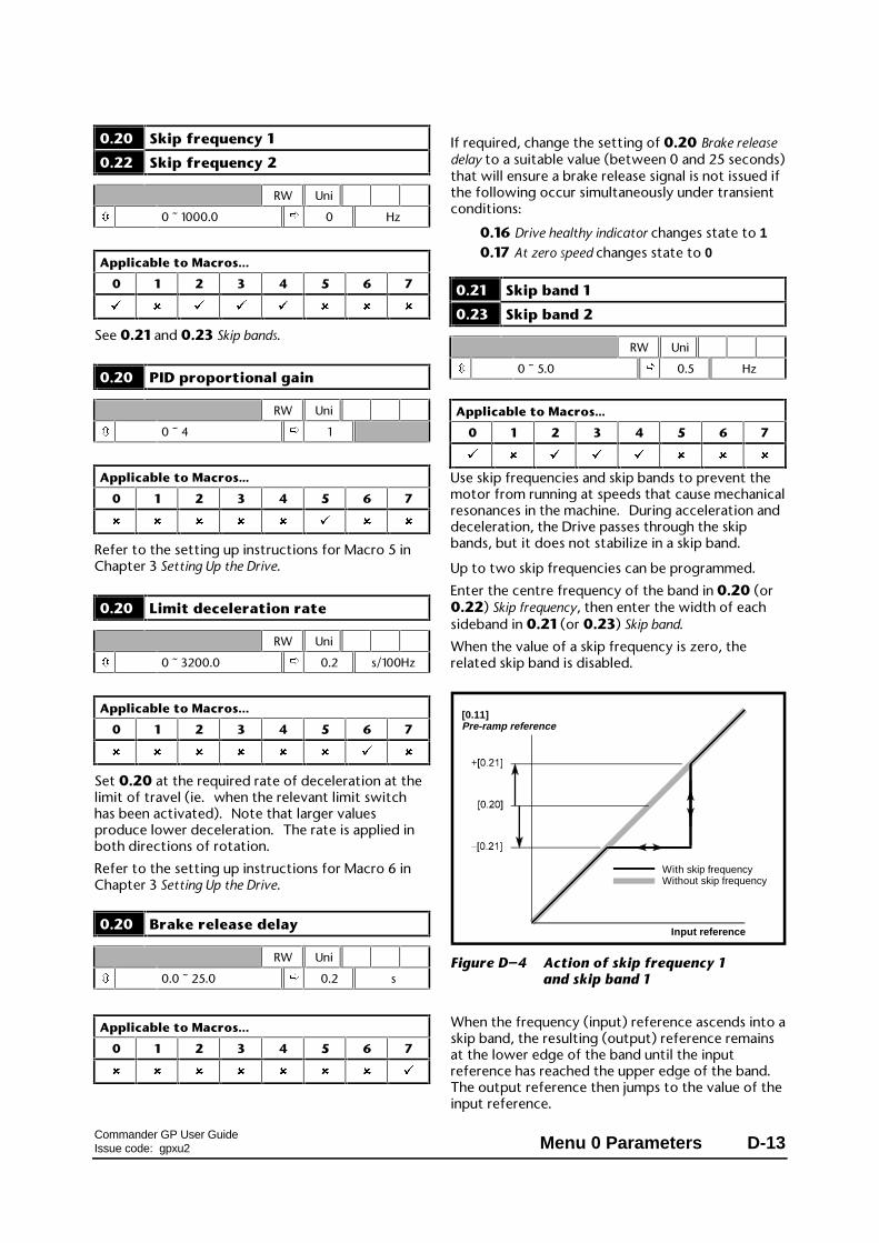
Commander GP User GuideIssue code: gpxu2 Menu 0 Parameters D-13
0.20 Skip frequency 1
0.22 Skip frequency 2
RW Uni
ô 0 ~ 1000.0 ð 0 Hz
Applicable to Macros...
0 1 2 3 4 5 6 7
ü û ü ü ü û û û
See 0.21 and 0.23 Skip bands.
0.20 PID proportional gain
RW Uni
ô 0 ~ 4 ð 1
Applicable to Macros...
0 1 2 3 4 5 6 7
û û û û û ü û û
Refer to the setting up instructions for Macro 5 inChapter 3 Setting Up the Drive.
0.20 Limit deceleration rate
RW Uni
ô 0 ~ 3200.0 ð 0.2 s/100Hz
Applicable to Macros...
0 1 2 3 4 5 6 7
û û û û û û ü û
Set 0.20 at the required rate of deceleration at thelimit of travel (ie. when the relevant limit switchhas been activated). Note that larger valuesproduce lower deceleration. The rate is applied inboth directions of rotation.
Refer to the setting up instructions for Macro 6 inChapter 3 Setting Up the Drive.
0.20 Brake release delay
RW Uni
ô 0.0 ~ 25.0 ð 0.2 s
Applicable to Macros...
0 1 2 3 4 5 6 7
û û û û û û û ü
If required, change the setting of 0.20 Brake releasedelay to a suitable value (between 0 and 25 seconds)that will ensure a brake release signal is not issued ifthe following occur simultaneously under transientconditions:
0.16 Drive healthy indicator changes state to 10.17 At zero speed changes state to 0
0.21 Skip band 1
0.23 Skip band 2
RW Uni
ô 0 ~ 5.0 ð 0.5 Hz
Applicable to Macros...
0 1 2 3 4 5 6 7
ü û ü ü ü û û û
Use skip frequencies and skip bands to prevent themotor from running at speeds that cause mechanicalresonances in the machine. During acceleration anddeceleration, the Drive passes through the skipbands, but it does not stabilize in a skip band.
Up to two skip frequencies can be programmed.
Enter the centre frequency of the band in 0.20 (or0.22) Skip frequency, then enter the width of eachsideband in 0.21 (or 0.23) Skip band.
When the value of a skip frequency is zero, therelated skip band is disabled.
[0.11] Pre-ramp reference
Input reference
With skip frequencyWithout skip frequency
Figure D–4 Action of skip frequency 1and skip band 1
When the frequency (input) reference ascends into askip band, the resulting (output) reference remainsat the lower edge of the band until the inputreference has reached the upper edge of the band. The output reference then jumps to the value of theinput reference.

Commander GP User GuideIssue code: gpxu2D-14 Menu 0 Parameters
When the frequency (input) reference descends intoa skip band, the resulting (output) reference jumpsimmediately to the lower edge of the band.
ExampleSkip frequency 1 = 20HZ
Enter 20 in parameter 0.20Required skip band = 4HzEnter 2 in parameter 0.21
(Skip band = 2 × Value of skip-band parameter.)
0.21 PID integral gain
RW Uni
ô 0 ~ 4 ð 0.5
Applicable to Macros...
0 1 2 3 4 5 6 7
û û û û û ü û û
Refer to the setting up instructions for Macro 5 inChapter 3 Setting Up the Drive.
0.21 Limit forward invert
RW Bit
ô 0 ~ 1 ð 0
Applicable to Macros...
0 1 2 3 4 5 6 7
û û û û û û ü û
Set 0.21 at 1 when the LIMIT FORWARD contact isnormally closed.
0.22 PID derivative gain
RW Uni
ô 0 ~ 4 ð 0
Applicable to Macros...
0 1 2 3 4 5 6 7
û û û û û ü û û
Refer to the setting up instructions for Macro 5 inChapter 3 Setting Up the Drive.
0.22 Limit reverse invert
RW Bit
ô 0 ~ 1 ð 0
Applicable to Macros...
0 1 2 3 4 5 6 7
û û û û û û ü û
Set 0.22 at 1 when the LIMIT REVERSE contact isnormally closed.
0.23 PID output high limit
RW Uni
ô 0 ~ 100 ð 100 %
Applicable to Macros...
0 1 2 3 4 5 6 7
û û û û û ü û û
Refer to the setting up instructions for Macro 5 inChapter 3 Setting Up the Drive.
0.24 PID output low limit
RW Bi
ô ±100 ð –100 %
Applicable to Macros...
0 1 2 3 4 5 6 7
û û û û û ü û û
Refer to the setting up instructions for Macro 5 inChapter 3 Setting Up the Drive.
0.25 PID output scale factor
RW Uni
ô 0 ~ 4 ð 1
Applicable to Macros...
0 1 2 3 4 5 6 7
û û û û û ü û û
Refer to the setting up instructions for Macro 5 inChapter 3 Setting Up the Drive.

Commander GP User GuideIssue code: gpxu2 Menu 0 Parameters D-15
0.24 Analog input 1 mode selector
0.25 Analog input 2 mode selector
RW Txt P
ô (See below) ð VOLt
0.24 – Applicable to Macros...
0 1 2 3 4 5 6 7
ü û ü ü ü û û û
0.25 – Applicable to Macros...
0 1 2 3 4 5 6 7
ü û û û û û û û
Set the required mode as follows:
Setting Input signal When currentsignal ≤≤3mA...
VOLt 0 0V to 10V
0–20 1 0 to 20mA Signal treated as zero
20–0 2 20mA to 0 Signal treated as zero
4–20.tr 3 4mA to 20mA Drive trips
20–4.tr 4 20mA to 4mA Drive trips
4–20.Lo 5 4mA to 20mA Drive runs at minimumor low speed
20–4.Lo 6 20mA to 4mA Drive runs at minimumor low speed
4–20.Pr 7 4mA to 20mA Drive runs at previousspeed
20–4.Pr 8 20mA to 4mA Drive runs at previousspeed
0.25 Motorized potentiometer resetindicator
RO Bit
ô 0 ~ 1 ð
Applicable to Macros...
0 1 2 3 4 5 6 7
û û ü û û û û û
When 0.25 is set at 1, this indicates that themotorized potentiometer output is reset to 0%. The motorized potentiometer is reset when theRESET contact is closed (terminal 25) (only whenMacro 2 is enabled).
0.25 Preset reference 1
0.26 Preset reference 2
0.27 Preset reference 3
0.28 Preset reference 4
RW Bi
ô ±1000 ð 0 Hz
Applicable to Macros...
0 1 2 3 4 5 6 7
û û û ü û û û û
Enter the required values.
0.25 Analog reference 1
RO Bi
ô ±1000 ð Hz
Applicable to Macros...
0 1 2 3 4 5 6 7
û û û û ü û û û
0.25 indicates the value of the torque referenceapplied to terminals 5 and 6 of the signal connector.
0.26 Motorized potentiometeroutput indicator
RO Bi S
ô ±100 ð %
Applicable to Macros...
0 1 2 3 4 5 6 7
û û ü û û û û û
0.26 indicates the value of the output of themotorized potentiometer as a percentage of themaximum value.

Commander GP User GuideIssue code: gpxu2D-16 Menu 0 Parameters
0.26 Analog input 2 mode selector
RW Txt P
ô (See below) ð VOLt
Applicable to Macros...
0 1 2 3 4 5 6 7
û û û û ü û û û
Set the required mode as follows:
Setting Input signal When currentsignal ≤≤3mA...
VOLt 0 0V to 10V
0–20 1 0 to 20mA Signal treated as zero
20–0 2 20mA to 0 Signal treated as zero
4–20.tr 3 4mA to 20mA Drive trips
20–4.tr 4 20mA to 4mA Drive trips
4–20.Lo 5 4mA to 20mA Drive runs at minimumor low speed
20–4.Lo 6 20mA to 4mA Drive runs at minimumor low speed
4–20.Pr 7 4mA to 20mA Drive runs at previousspeed
20–4.Pr 8 20mA to 4mA Drive runs at previousspeed
0.26 Post-scaling PID reference
0.27 Post-scaling PID feedback
RO Bi
ô ±1000 ð Hz
Applicable to Macros...
0 1 2 3 4 5 6 7
û û û û û ü û û
These parameters are used for monitoring the PIDreference and PID feedback. Refer to Macro 5 inChapter 3 Setting Up the Drive.
0.27 EUR> Positive logic selectUSA> Sequencing mode selector
Applicable to Macros...
0 1 2 3 4 5 6 7
ü û û û û û û û
European configuration
Positive logic select RW Bit R P
ô 0 ~ 1 ð 0
Use 0.27 to select the logic polarity of the digitalinputs, as follows:
0 Negative logic
1 Positive logic
USA configuration
Sequencing modeselector
RW Uni P
ô 0 ~ 4 ð 4
Use 0.27 to change the functions of the digitalinputs; these functions determine the digital controlmode.
The default setting (4) gives the functions shown inthe signal connection diagrams in Chapter 3 Settingup the Drive.
Set 0.27 at 0 for digital control by momentarycontacts. See Macro 0 in Chapter 3 Setting up theDrive.
It is essential that you see 0.29 USA> Terminal-29destination selector in order to set up a RUN PERMIT /STOP input.
For other settings of 0.27, see the Commander GpAdvanced User Guide.

Commander GP User GuideIssue code: gpxu2 Menu 0 Parameters D-17
0.27 Motorized potentiometerzero-start select
RW Bit
ô 0 ~ 1 ð 0
Applicable to Macros...
0 1 2 3 4 5 6 7
û û ü û û û û û
Set 0.27 for the way the motorized potentiometeris to behave at power-up of the Drive as follows:
0 The motorized-potentiometer output returns tothe value it held when the Drive was previouslypowered-down
1 The motorized-potentiometer output starts atzero
0.27 Analog reference 2
RO Bi
ô ±100 ð %
Applicable to Macros...
0 1 2 3 4 5 6 7
û û û û ü û û û
0.27 indicates the value of analog input 2 as apercentage of the full-scale value.
Analog input 2 is used for the frequency referencewhen Macro 4 is being used in frequency control. Inthis case, analog input 2 is not used for torquecontrol.
0.28 EUR> Current-loopproportional gain
RW Uni
ô 0 ~ 30 000 ð 20
Applicable to Macros...
0 1 2 3 4 5 6 7
ü û û û û û û û
Do not adjust this parameter.
0.28 Motorized potentiometerbipolar select
RW Bit
ô 0 ~ 1 ð 0
Applicable to Macros...
0 1 2 3 4 5 6 7
û û ü û û û û û
Set 0.28 as follows:
0 Unipolar output (0 ~ 100%)
1 Bipolar output (±100%)
0.28 USA> Frequency demand
RO Bi P
ô ±1000 ð HZ
Applicable to Macros...
0 1 2 3 4 5 6 7
ü û û û û û û û
USA configuration
0.28 differs from 0.11 Pre-ramp reference in that itindicates the demanded reference before frequencylimiting and skip bands.

Commander GP User GuideIssue code: gpxu2D-18 Menu 0 Parameters
0.29 EUR> Current-loop integral gainUSA> Terminal-29destination selector
Applicable to Macros...
0 1 2 3 4 5 6 7
ü û û û û û û û
European configuration
RW Uni
ô 0 ~ 30 000 ð 40
Do not adjust this parameter.
USA configurationRW Uni R P
ô 0.00 ~ 20.50 ð 1.41 Menu.parameter
Use 0.29 to change the function of the digital inputon terminal 29.
The default setting (1.41) gives LOCAL/REMOTEswitching.
When 0.27 Sequencing mode selector is set at 0, it isessential that you set 0.29 at 6.34. This makesterminal 29 function as a stop input(RUN PERMIT / STOP).
0.29 Motorized potentiometer rate
RW Uni
ô 0 ~ 250 ð 20 s
Applicable to Macros...
0 1 2 3 4 5 6 7
û û ü û û û û û
Enter the required time for themotorized-potentiometer output to change by100%.
0.28 Analog input 2 (PID reference)scaling
0.29 Analog input 3 (PID feedback)scaling
RW Uni
ô 0 ~ 4 ð 1
Applicable to Macros...
0 1 2 3 4 5 6 7
û û û û û ü û û
If required, change the scaling of the PID referenceand feedback inputs by entering appropriate valuesin these parameters.
0.29 Analog input 1(Torque reference) scaling
0.30 Analog input 2(Frequency reference) scaling
RW Uni
ô 0 ~ 4 ð 1
Applicable to Macros...
0 1 2 3 4 5 6 7
û û û û ü û û û
If required, change the scaling of the torquereference and frequency reference inputs byentering appropriate values in these parameters.
0.30 FWD/REV key enable
RW Bit
ô 0 ~ 1 ð 0
Applicable to Macros...
0 1 2 3 4 5 6 7
ü û û û û û û û
The Drive is supplied with the key disabled. To enable this key, set 0.30 FWD/REV enable at 1.

Commander GP User GuideIssue code: gpxu2 Menu 0 Parameters D-19
0.30 Motorized potentiometeroutput scale factor
RW Uni
ô 0 ~ 4 ð 1
Applicable to Macros...
0 1 2 3 4 5 6 7
û û ü û û û û û
By default, when the motorized potentiometeroutput is 100%, the frequency is set at 100%. Ifnecessary, enter the required value to reduce thefrequency range.

Commander GP User GuideIssue code: gpxu2D-20 Menu 0 Parameters
Pr Macro 0 Macro 2 Macro 3 Macro 4
0.11 Pre-ramp reference Pre-ramp reference Pre-ramp reference Pre-ramp reference
0.12 Post-ramp reference Post-ramp reference Post-ramp reference Post-ramp reference
0.13 Motor active-current Motor active-current Motor active-current Motor active-current
0.14 Jog reference Jog reference Jog reference Jog reference
0.15 Ramp mode selector Ramp mode selector Ramp mode selector Ramp mode selector
0.16 Stop mode selector Stop mode selector Stop mode selector Stop mode selector
0.17 Torque mode selector Status relay invert Status relay invert Status relay invert
0.18 S-ramp enable S-ramp enable S-ramp enable S-ramp enable
0.19 S-ramp da/dt limit S-ramp da/dt limit S-ramp da/dt limit S-ramp da/dt limit
0.20 Skip frequency 1 Skip frequency 1 Skip frequency 1 Skip frequency 1
0.21 Skip band 1 Skip band 1 Skip band 1 Skip band 1
0.22 Skip frequency 2 Skip frequency 2 Skip frequency 2 Skip frequency 2
0.23 Skip band 2 Skip band 2 Skip band 2 Skip band 2
0.24 Analog input 1 modeselector
Analog input 1 modeselector
Analog input 1 modeselector
Analog input 1 (torquereference) mode selector
0.25 Analog input 2 modeselector
Motorized pot. reset Preset reference 1 Analog input 1(torque reference)
0.26 Motorized pot. outputindicator
Preset reference 2 Analog input 2 (frequencyreference) mode selector
0.27 EUR> Positive logic select
USA> Sequencing modeselector
Motorized pot. zero-startselect
Preset reference 3 Analog input 2 (speedreference)
0.28 EUR> Current-loopproportional gain
USA> Frequency demand
Motorized pot. bipolarselect
Preset reference 4 Over-speed threshold
0.29 EUR> Current-loopintegral gain
USA> Terminal-29destination selector
Motorized pot. rate Analog input 1 scaling
0.30 FWD/REV key enable Motorized pot. outputscale factor
Analog input 2 scaling

Commander GP User GuideIssue code: gpxu2 Menu 0 Parameters D-21
Pr Macro 5 Macro 6 Macro 7
0.11 Pre-ramp reference Pre-ramp reference Pre-ramp reference
0.12 Post-ramp reference Post-ramp reference Post-ramp reference
0.13 Motor active-current Motor active-current Motor active-current
0.14 Analog input 1 (frequencyreference) mode selector
Limit forward indicator Motor current magnitude
0.15 Analog input 2(PID reference) modeselector
Run forward indicator Current detected indicator
0.16 Analog input 3(PID feedback) modeselector
Run reverse indicator Drive healthy indicator
0.17 Analog input 1(frequency reference)
Limit reverse indicator At zero speed indicator
0.18 Analog input 2(PID reference)
Stop mode selector Brake release indicator
0.19 Analog input 3(PID feedback)
Hold zero speed enable Current threshold
0.20 PID proportional gain Limit deceleration rate Brake release delay
0.21 PID integral gain Limit forward invert
0.22 PID derivative gain Limit reverse invert
0.23 PID output high limit
0.24 PID output low limit
0.25 PID output scale factor
0.26 Post-scaling PID reference
0.27 Post-scaling PID feedback
0.28 Analog input 2 scaling
0.29 Analog input 3 scaling
0.30

Commander GP User GuideIssue code: gpxu2D-22 Menu 0 Parameters

Commander GP User GuideIssue code: gpxu2 Diagnostics E-1
E Diagnostics
Warning
Users must not attempt torepair a Drive if it is faulty, norcarry out fault diagnosis otherthan through the use of thediagnostic features describedin this appendix.Under no circumstances mustthe casing of the Drive beopened when the AC supply isconnected.If a Drive is faulty, it must bereturned to an authorizedControl Techniques distributorfor repair.
When the Drive display is in Status mode, it is usedfor displaying coded messages. These arecategorized as follows:
Status indicationsWhen the Drive is in normal operation, thelower display shows a code which indicates thestatus of the Drive.
Alarm indicationsIf a critical condition is detected, the Drivecontinues operating and the lower displayshows an alarm code in place of the statuscode. If the condition is not rectified, the Drivecould trip.The alarm message flashes alternately with thenormal display indication.
Trip codesIf the Drive trips, the output is disabled so thatthe Drive stops controlling the motor. Thelower display indicates that a trip has occurredand the upper display shows a trip code.
E.1 Status indications
Lowerdisplay
Conditions Driveoutput
rdY
The Drive is ready to be run. Enabled
run
The Drive is running. Enabled
inh
The Drive cannot be run and is waiting toenter the ready (rdY) state
Disabled
StoP
The Drive is holding the motor atzero speed.
Enabled
dEC
The Drive is decelerating the motor. Enabled
SCAn
The Drive is searching for the motorfrequency when synchronizing to aspinning motor.
Enabled
dc
The Drive is applying DC injection braking. Enabled
triP
The Drive has tripped and is no longercontrolling the motor. The trip codeappears on the upper display.
Enabled
E.2 Alarm indications
Lowerdisplay
Conditions
br.rS
The braking-resistor [I x t] accumulator in the Drive hasreached 75% of the value at which the Drive will betripped.
OVLd
The motor [I x t] accumulator in the Drive has reached 75%of the value at which the Drive will be tripped.
hot
The Drive heatsink has reached 95°C (203°F) and theoutput current has not been reduced (sufficiently).
Air
The temperature of the air around the control circuits isnear the maximum permissible.

Commander GP User GuideIssue code: gpxu2E-2 Diagnostics
E.3 Trip codes
Lowerdisplay
No. Conditions
UU 1
Insufficient DC-bus voltage.
This occurs when the AC supply is removed.
OU 2
Excessive DC-bus voltage.
Excessive regenerated power caused by the following:0.04 Deceleration rate value too lowBraking resistor not being used
OI.AC 3
Excessive output current caused by:0.03 Acceleration rate value too low0.04 Deceleration rate value too lowExcessive motor-cable capacitanceShort-circuit at the output of the Drive
OI.br 4
Excessive current in the braking resistor.
A short-circuit exists across the braking resistor.
PS 5
Internal power supply fault.
Remove and re-connect the AC supply. If the trip persists,contact the supplier of the Drive.
Et 6
External trip signal applied to terminal 30.
Remove the trip signal, then reset the Drive.
OV.SPd 7
The motor has exceeded the over-speed threshold.
This can be caused by the following:Sudden removal of a large mechanical load0.04 Deceleration rate too lowInappropriate 0.16 Stop mode setting0.19 S-ramp da/dt too high (not used in Macro 5)
SEP 9
Trip in UD50 small option module. For more information,see the User Guide.
ENC.PH8 18
Autotune fail (limit-switch operated, trip, etc).
It.br 19
Excessive braking-resistor [I x t]
It.AC 20
The [I x t] thermal overload accumulator has reached 100%(see the OVLd alarm).
Oh1 21
Excessive heatsink temperature due to excessive [I xt](see the hot alarm).
Oh2 22
Excessive heatsink temperature detected by thermistor.
OA 23
The temperature of the air around the control circuits isexcessive (see the Air alarm).
th 24
The motor thermistor has detected excessive motortemperature (or the thermistor or wiring is open-circuit).
thS 25
The motor thermistor or wiring is short-circuit.
OP.OVLd 26
The total current drawn from terminals 22 and 24exceeds 200mA.
cL1 27
When configured for current signal, loss of signal currentat terminals 5 and 6 (Analog input 1).
cL2 28
When configured for current signal, loss of signal currentat terminal 7 (Analog input 2).
cL3 29
When configured for current signal, loss of signal currentat terminal 8 (Analog input 3).
SCL 30
Loss of serial communications with the Universal RemoteKeypad
EEF 31
Fault in the internal EEPROM causing loss of parametervalues.
Follow the procedure Restoring all parametersto the default values in Appendix A, then re-enter the valuesfor the application.
Ph 32
Loss of an AC supply phase.
rS 33
Incorrect measurement of stator resistance due to thefollowing:
Motor cable disconnected when the measurement wasbeing madeMotor too small for the Drive
See Autotune in Chapter 2 Getting Started.

Commander GP User GuideIssue code: gpxu2 Diagnostics E-3
Lowerdisplay
No. Conditions
SEP.diS 180
The UD55 small option module has been removed or is notfitted correctly.
Perform either of the following:
Ensure a UD55 small option module is correctly fitted
To operate the Drive without a UD55, set parameter .00at 1000 and press the STOP/RESET key.
FSH.Err 182
The memory of the UD55 small option module has beenfound to be corrupt. If the trip has occurred at power-up,the memory is automatically re-formatted and all theparameter-sets are erased. If the trip occurs after power-up, the memory and parameter-sets are unaffected. Seethe UD55 User Guide.
FSH.Dat 183
No values have been found in the selected parameter-set inthe UD55 small option module. Consequently, no valueshave been copied to the destination Drive.
FSH.TyP 184
The operating mode of the destination Drive is differentfrom that related to the selected parameter-set in theUD55 small option module. Consequently, no values havebeen copied to the destination Drive. Select anappropriate parameter-set.
FSH.ACC 185
Write-access to the UD55 small option module has notbeen enabled. Consequently, no values have been copiedto the destination Drive. To enable write-access, connecttogether terminals 40 and 41 on the UD55.
FSH.rng 188
The current rating or voltage rating of the destinationDrive is different from that relating to the selectedparameter-set in the UD55 small option module. Consequently, all parameter values have been copied tothe destination Drive except for those listed in Transferringparameter-sets between Drives of different ratings in the UD55User Guide.

Commander GP User GuideIssue code: gpxu2E-4 Diagnostics