Embed Size (px)
Citation preview

1
USER GUIDE
Diagnostic Web Server FW ver. 6.0.51
BrightSign, LLC. 16780 Lark Ave., Suite B Los Gatos, CA 95032 | 408-852-9263 | www.brightsign.biz

TABLE OF CONTENTS Introduction 1
Setup 2
Setting up the DWS in BrightAuthor 2
Setting up the DWS (Advanced) 3
Accessing the Diagnostic Web Server 3
Using the Diagnostic Web Server 5
Info 5
Log 6
Control 6
SD 6
Diagnostics 7
Channel Scan Diagnostics 9
Video 10
Application 10
Custom Tabs (Advanced) 10

1
INTRODUCTION The Diagnostic Web Server (DWS) allows you to view and modify various settings on a networked BrightSign player. You can access the DWS with the BrightSign App or with a web browser on any computer connected to the local network. This guide will walk you through setting up and using the features of the Diagnostic Web Server.
2
SETUPThe Diagnostic Web Server is enabled out of the box. If you'd like to access the DWS before performing the player setup process, skip ahead to the Accessing the DWS section. Otherwise, follow the below steps to configure the DWS during the player setup process.
Setting up the DWS in BrightAuthor Follow these steps to enable and configure the DWS during the player setup process in BrightAuthor:
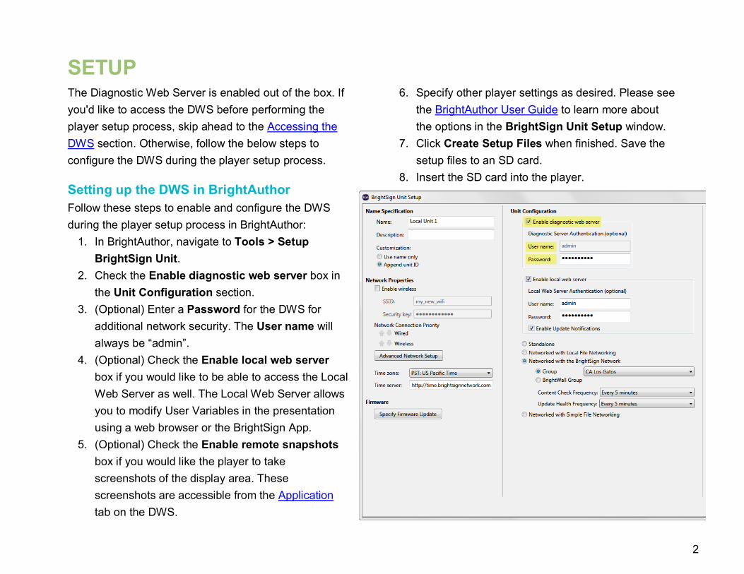
1. In BrightAuthor, navigate to Tools > Setup BrightSign Unit.
2. Check the Enable diagnostic web server box in the Unit Configuration section.
3. (Optional) Enter a Password for the DWS for additional network security. The User name will always be “admin”.
4. (Optional) Check the Enable local web server box if you would like to be able to access the Local Web Server as well. The Local Web Server allows you to modify User Variables in the presentation using a web browser or the BrightSign App.
5. (Optional) Check the Enable remote snapshots box if you would like the player to take screenshots of the display area. These screenshots are accessible from the Application tab on the DWS.
6. Specify other player settings as desired. Please see the BrightAuthor User Guide to learn more about the options in the BrightSign Unit Setup window.
7. Click Create Setup Files when finished. Save the setup files to an SD card.
8. Insert the SD card into the player.

3
9. Power up or power cycle the player. Once the player boots up and establishes an IP address, you will be able to access the Diagnostic Web Server.
Setting up the DWS (Advanced) You can also confiugre the Diagnostic Web Server using the BrightSign serial command prompt or a custom script. Input the following commands in the serial prompt to run the DWS on the standard port:
>>registry write networking http_server 80
>>registry flush
Include the following arguments in a custom script to run the DWS on the standard port:
>>registrySection = CreateObject
(“roRegistrySection”, “networking”)
>>registrySection.Write (“http_server”,”80”)
>>registrySection.Flush()
Note: A registry flush is necessary if you plan to power cycle the unit after executing the registry command. Registry writes will buffer for a few seconds because the EEPROM and NAND have a limited number of writes (and thus need to protect against carrying out too many writes too quickly).
By default, a DWS instance that is set up using these methods does not require a password. By setting up a password, you can enable digest authentication. Input the following command in the serial prompt to create a password:
>>registry write networking http_auth “password”
Use the username “admin” and your chosen password when connecting to the DWS.
Accessing the DWS Follow these steps to access the Diagnostic Web Server,
1. If you don't know the IP address of the player, do the following: a. Power off the player by unplugging the power
supply. b. Remove the SD card (as well as the internal
µSD or card or SSD drive, if applicable). c. Power on the BrightSign player by reconnecting
the power supply. d. Wait for the player to boot up: The IP address of
the player will be displayed on the screen. 2. Enter the IP address of the networked player into
the address bar of a web browser: a. If you've set up the DWS with a password, enter
the password.

4
b. If you haven't performed the player setup process yet, use the serial number of the player as the password.
Note: The username is always "admin". To access the Local Web Server, enter the same IP address as above, with the addition of port 8008 at the end (e.g. “10.1.0.99:8008”). Note: Since the Local Web Server is used to modify User Variables on a player, it will be inaccessible if the current presentation has no User Variables.

5
USING THE DIAGNOSTIC WEB SERVERThe Diagnostic Web Server user interface consists of several tabs. This chapter will detail the information and settings offered by each tab.
Info This page provides general information about the player and its current status: • Time: The current time as it is configured on the
player. Click set to configure the time on the player: o Automatically: Click Use Current Time to set the
time of the player using the current time of the browser. Note that the listed Time and Date refer to the time reported by the browser when this page was loaded.
o Manually: Enter a Time and Date to set on the player. These values will go into effect the moment you click the Set Time button. If you would like to interpret the date/time using the time zone of the player, check the Apply Timezone box. Otherwise, the date/time will be applied as a UTC value.
Note: You cannot edit the time zone of the player from the DWS. To change the time zone, you will need to perform the player setup process again. • Name: The user-supplied name of the player
• Description: An optional user-supplied description for the player
• Model: The model number of the player • Unique ID: The serial number of the player • (Ethernet/WiFi) IP: The IP address of the player • (Ethernet/WiFi) MAC: The media access control
(MAC) address of the player • Boot Version: The current version of the boot loader. • Firmware Version: The current version of firmware
installed on the player

6
• Video Mode: The current video resolution of the presentation on the player. You can change the video resolution of the presentation in the Video tab
• Uptime: The amount of time the player has been powered on and working correctly
• PoE: The status of the PoE interface (applicable to 4Kx42 and XDx32 models only)
• Extensions: A list of Firmware Extensions currently installed on the player
• Change password: Changes the password settings for logging into the DWS: o Change Password: Enter the password twice and
click Set Password to modify the existing DMS password.
o Remove Password: Enter the current DMS password and click Remove Password to disable the password protection for the DMS.
Log This page provides a log of system processes and events on the player. The output is similar to the information generated through a serial, Telnet, or SSH connection.
Control This page allows general control of the system processes of the player: • Reboot: Reboots the player remotely.
• Force Recovery: Sends the player into recovery mode by deleting instances of autorun.brs from all available storage devices (SD, uSD, USB) and rebooting the player.
• Reboot with Log: Reboots the player while preserving the current log file.
SD This page provides a listing of all files on the SD card. Depending on the type of file, there will be several options:
Explore: Opens the specified file directory. Use the Upload to this directory option near the bottom of the page to upload a file to the current directory.
Download: Downloads a file from the SD card to your computer. This is helpful if you need to view autorun or log files, but don’t want to disable the player by removing the SD card.
View: Allows you to view the contents of a file as plain-text webpage.
Edit: Gives access to various file-editing tools: • Delete: Deletes the file. • Rename: Provides various options for renaming
the file. You can specify a custom name or choose from among a list of common filenames.
• Set Autorun: Sets the file as the current autorun by copying the file and renaming it “autorun.brs”.

7
The replaced autorun file will be preserved as “autorun.backup”. Note: The system does not check the integrity of the new autorun file (i.e. any file can be assigned as the autorun file). • Content Playback: Replaces the current
autorun on the device with a script that will attempt to play back the current file (the replaced autorun will be renamed). You will need to observe the video output to learn the
results of the script. The current video mode will be displayed on screen for 5 seconds before displaying the content.
• Video Mode Test: An extension of the Content Playback test described above, this script will also cycle through all video modes.
Diagnostics This page provides various network and system tools that are helpful for diagnosing problems and getting information about a BrightSign player: • Network Diagnostics: Runs network diagnostics.
This process may take some time to complete, especially when certain tests fail.
• DNS Lookup: Tests the specified DNS address to check whether name resolution is working.
• PING: Pings a device with the specified IP address or DNS name.
• Trace Route: Performs a standard traceroute diagnostic on the specified IP/DNS address. Check the Resolve IP Addresses box to resolve the specified DNS name.
• Download Speed Test: Tests the download speed of the network connection against the specified URL.
o Ignore Proxy Settings: Check this box if you have a proxy configured for your player and would like to ignore this proxy setting for the speed test.

8
o Test Storage Speed: Check this box to store the URL target on available storage. This option will likely yield more accurate download speed test results.
• Network Configuration: Provides extensive information about network interface settings.
• Network Neighborhood: Displays information on the current network neighborhood.
• Network Packet Capture: Provides access to tcpdump functionality.
o Source: Select a network interface to use for packet capture.
o Capture filename: The name of the capture file, which will be saved on the primary storage device of the player
o Capture time: The duration of the packet capture operation
o Capture number of packets: The number of packets to capture before concluding the process
o Capture size: The maximum size of each packet. Specifying 0 will instruct the function to capture the entire packet no matter the size.
o Filter: A field for conditional filtering of packets. This operation uses standard pcap syntax.
o Start: Begins the packet capture process. Once the process begins, you can click Stop to prematurely halt packet capture.
o Refresh Status: Returns you to the capture options section if the capture process is complete.
• Disable Autorun: Causes the player to reboot and disables the autorun script when the device restarts. This allows the unit to display the firmware version and IP address on screen (if the unit is connected to a local network). If the player has a serial port, you will
9
be able to access the system shell over a null-modem serial cable.
• Channel Scan: Takes you to the Channel Scan Diagnostics page, which provides options for scanning the RF modulator (available on the XD1230 only). Please see the following section for more information.
• Format Storage: Takes you to the Format Storage page, which allows you format storage devices attached to the player.
o Storage: Select a storage device. You can only format storage devices that are currently unformatted; storage that already contains content files or autorun scripts cannot be reformatted.
o File system: Select a supported file system to use when formatting the storage device.
Channel Scan Diagnostics XD1230 Only • Scan: Allows you to retrieve channel information
(including frequency, video PID, and audio PID) from the RF input.
o Channel Map: Choose “ATSC”, “QAM”, or “ATSC and QAM”. Please consult your source provider for more information.
o Modulation Type: Choose “QAM 64”, “QAM 256”, or “QAM 64 and QAM 256”. Please
consult your source provider for more information.
o (Optional)First RF Channel: Specify a lower limit for the range of the channel scan.
o (Optional)Last RF Channel: Specify an upper limit for the range of the channel scan.
Note: If you do not specify an upper and/or lower limit for the channel scan, the player will scan the entire range of possible channels. A complete scan will take a substantially longer amount of time. o Save Results To Storage: Check this box to
save the results of the channel scan to the SD card in addition to displaying it on screen.
o Generate Scan Debugging: Check this box to save a script log of the channel scan to the SD card.
o Begin Scan: Click this button once you have specified the options above to start the scanning process. Results will be shown on the attached display device.
• Download Scan Results: Copies the results of the above channel scan from the local storage of the player to your computer. You can also retrieve the channel data by downloading the “ScanResults.xml” file in the SD tab once the scan is complete

10
• Download Scan Diagnostics: Copies the results of the diagnostics generated by the channel scan from the local storage of the player to your computer.
Video This page provides several diagnostic tools related to the video settings of the player: • Current Video Mode: The video resolution currently
being output by the player • Change Video Mode: Changes the display
mode/resolution of the player on all video outputs (HDMI, VGA, Component). The device will reboot and disable the current autorun script (similar to the Disable Autorun button in the Diagnostics tab). Otherwise, the autorun script will reset the video mode of the player by default.
• Video Mode Test: Replaces the current autorun on the player with a custom script that tests all possible video modes (the current autorun will be renamed instead of being deleted). The custom script will display the current mode on screen for five seconds before transitioning to the next video mode; you will need to observe the output on the connected display to see the results of the script.
• Powersave: Enables or disables the “powersave” mode on the HDMI/VGA output.
Application Clicking the Application tab takes you to the BrightSign Application Server (BAS). The BAS hosts the Remote Snapshot application. If you enabled the Remote Snapshot feature during player setup, you can view screenshots of the display area here.
Custom Tabs (Advanced) You can use the DWS to link to a customizable set of hosted files. This functionality requires a custom autorun or BrightAuthor plugin. See the entry for the roHttpServer.SetupDWSLink() method in the BrightScript Object Reference Manual for more details.


![User Guide...User. {{]}]} {}]}](https://img.dokumen.tips/doc/110x75/60918ca14327954d24291644/-user-guide-user-.jpg)