Embed Size (px)
Citation preview
Use of the Carbon Arc and Burning Magnesium asThermal Sources for Experimental Burns *
THOMAS P. DAVIS, M.S., HERmAN E. PEARSE, M.D.
From the Department of Radiation Biology and the Department of Surgery,The University of Rochester School of Medicine and Dentistry,
Rochester, New York
IntroductionTHE ATOMIC BOMBING of Hiroshima and
Nagasaki caused a large number of casual-ties from skin burns due to a short exposurefrom high intensity thermal radiation. In1947, we began studying these "flash burns"in the laboratory,14 and in the last ten yearsseveral thermal sources for this purposehave been investigated. To date, we believethat the carbon arc furnace is the bestsource for small area burn production, andthat the burning of magnesium flash powderis the best method of creating large areaflash burns. The development and perform-ance of these two thermal sources are de-scribed.
This equipment has the added advantageof precise control of the thermal dose sothat research may be done on the factorswhich govern the local burn. It has beenknown since the work of Moritz and Hen-riques 13 that both time and temperatureare critical in the degree of severity ofburns. Yet many investigators have re-ported observations on physiologic changesfrom burns produced by flame, steam, hotwater or a hot iron, in which these factorswere not accurately controlled. The lesionscreated in successive experiments differ inseverity unless the thermal dose is con-trolled.
* Submitted for publication February 21, 1958.This paper is based on work performed under
contract with the United States Atomic EnergyCommission at the University of Rochester AtomicEnergy Project, Rochester, New York.
The Carbon ArcIn 1947, consultation with Dr. E. 0. Hul-
burt, Director of Research, Naval ResearchLaboratory, led to the suggestion thatfocusing the beam from a carbon arc on atest object might be a good method forproducing radiant energy burns. It wasthen found that carbon arc searchlightswere already being used for a similar pur-pose at the Material Laboratory of theBrooklyn Naval Shipyard under the direc-tion of Dr. Rudolph Langer. We set upsuch an arc, and at the same time exploredother possibilities. The "exploding wire" ofAnderson,' spark discharge from a bankof condensers and discharge from an Edger-ton tube 6 were tried but were not satisfac-tory for our needs. A solar furnace wasconsidered but discarded as impractical inour climate. High temperature furnaces,using a bank of gas burners, oxyacetyleneflame, burning aluminum in oxygen or anelectric current through graphite resistorswere tried elsewhere. Such furnaces sufferfrom such disadvantages as inadequatethermal energy output, unsuitable spectraldistribution or excessive cost. We concludedthat the focused beam from a carbon arcwas the best method for producing thesmall area burns which we wished to study.
Figure 1 illustrates the optical system forfocusing the beam from a carbon arc bymeans of two parabolic mirrors. Our firstequipment of this sort included a 24-inchArmy carbon arc searchlight with a rotaryshutter.14 This was satisfactory for small
68

Volume 149Number 1
THERMAL SOURCES FOR EXPERIMENTAL BURNS
aRr w
A+
-r -1 a
I8'
SCHEME FOR OPTICAL SYSTEM OF 60 INCH SEARCHLIGHT(PARABOLIC. MIRRORS )
FIG. 1. The parabolic mirror of the searchlight, A, reflects the rays from the carbon crater,S. These are focused by a second parabolic mirror A' at the spot S'. The animal P is exposedon a moving car having a known rate of traverse. A strip burn is produced.
SCHEME FOR OPTICAL SYSTEM OF 24 INCH SEARCHLIGHT
( ELLIPSOIDAL MIRROR )
FIc. 2. The primary focus of the ellipsoidal mirror is at the carbon crater S. The secondary
focus, 5', is 52 inches from the mirror where the image is enlarged about five times to expose
the aniimal, P.
69
|

DAVIS AND PEARSE Annals of SurgeryJanuary 1959
FIG. 3. The 24-inch carbon arc searchlight as modified for producing small areaflash burns. The ellipsoidal mirror has an adjustable mount (1). One type of dia-phragm for control of the radiant thermal energy is shown at (2). For illustrationboth types of timing shutters are in place: the wheel (3) for simulating the shape ofa bomb pulse and the solenoid activated opening and closing shutter (4) for a"square" pulse. The test object or animal is placed on an adjustable table (5) againsta water-cooled port 1.7 cm. in diameter (not shown) which is centered on the focalspot and limits the area exposed. All control equipment is mounted in a panel (6) forease of operation.
test objects but a large animal obscured a
considerable fraction of the beam. The nextstep was to increase the size of the opticalsystem by using 60-inch mirrors. This in-creased the radiant power obtainable toabout 90 cal./cm.2 sec. and decreased the
relative obscuration by the test animal.
Time of exposure was regulated by movingthe animal across the focal spot on a car
with its rate of traverse controlled. Thisequipment still had two disadvantages: itsfocal spot was very small and the angle ofthe rays from the edge of the mirror was
about 600.
70

THERMAL SOURCES FOR EXPERIMENTAL BURNS
FIG. 4. Thirty-six small area bums from the carbon arc source may be placed onone side of a white pig. By using both sides 72 observations are made on one animal.In this illustration the lesions increase in severity from erythema on the right to car-bonized bums on the left. In experimental work the lesions are randomized.
Meanwhile development of carbon arc
furnaces using essentially the same opticalsystem was being carried on at the Brook-lyn 12 and San Francisco 3 Naval Shipyards,and at Richmond.16
In order to overcome the disadvantagesinherent in the use of two parabolic mir-rors, we changed, in 1950, to an opticalsystem in which the 24-inch parabolic mir-ror of an Army searchlight was replaced byan ellipsoidal mirror (Fig. 2). This is posi-tioned by an adjustable mount to place thepositive carbon crater at the first focal point.An image of this source, enlarged about fivetimes, is then obtained at the second focalpoint with the greatest angle of incidencebeing only about 160. This arc uses a Na-tional Carbon Co. "Ultrex" 10 mm. positivecarbon with an arc current of about 140amperes. The spectral distribution corre-
sponds approximately to that from a black
body at 5,800° K. The equipment is shownin Figure 3.At the exposure plane the maximum ir-
radiance is 34 cal./cm2.-sec. for this system.An adjustable diaphragm and attenuatingscreens are used to control the irradiance,which can be reduced to as little as 0.1cal./cm2.-sec.For producing a "square pulse," a shutter
consisting of two light aluminum vanes, one
for opening and one for closing, actuatedby rotary electrical solenoids is used. Syn-chronous motor driven cams provide pre-cise timing of exposures from 0.1 second to100 seconds or more.
For obtaining a "shaped pulse," a wheelwas devised 11 50 inches in diameter,mounted with its edge just below the con-
verging beam of radiation. Radially dis-posed pickets, adjusted for width and spac-
ing, cut into the beam and give the degree
Volume 149Number 1 71

DAVIS AND PEARSE Annals of SurgeryJanuary 1959
t'.INTAKE FAN
2- SWITCH -BOX
3- HATiCH CONTROL4- COVERED LEAD WIRES
5- BRASS GROUNDING PLATE6- BALLAST RESISTOR7- H.V. TRANSFORMER -78- TRAY9- ELECTRODE10- STEEL STORAGE CABINET FOR Mg.II- GROUND TO WATER PIPE12- RED LINE
FIG. 5. A diagrammatic sketch of the laboratory for firing magnesium flash powder. Theanimal is placed on the table beyond the tray (8). Safety precautions must be completedbefore crossing the red line (12).
of attenuation desired. The total time ofexposure is controlled by the speed of rota-tion of the wheel, so that pulses with a widevariety of shape and duration may beobtained.The characteristics of the irradiation
from such an arc source may be measuredin several ways. To obtain the absolutevalue of the output energy, a copper spherecalorimeter designed in this laboratory 2 iSused. The spatial distribution in the ex-
posure plane is obtained by probing thespot with a photo cell behind a pin pointopening. The spectral distribution was de-termined by a special spectrophotometer 10
constructed for this purpose. Appropriatefilters may be placed in the beam if it is
desired to alter the spectrum of the radia-tion applied.The exposed area on the test animal is
limited by means of a water-cooled portwhich is 1.7 cm. in diameter. The spatialvariation of irradiance within the centralcircular area of 1 cm2. is about 12 per cent.2This small area permits as many as 36 burnsto be placed on each side of a 12 Kg. whitepig (Fig. 4). Results are analyzed by sta-tistical methods.The carbon arc furnace has the advan-
tages of high and constant irradiance, goodreproducibility, and ease of control of theexposure parameters. These permit analysisof the factors which modify burn severity,where precise control of the thermal dose
72

THERMAL SOURCES FOR EXPERIMENTAL BURNS
FIG. 6. Closeup of the equipment for firing magnesium. The flash powder is spreadacross the Y-shaped tray (1) and detonated by the electrode (2). A calorimeter (3)is on one side at the same distance from the charge as the pig (4) on the other side.In this illustration the animal is shielded by a transite plate (5) except for a 3-inchcircular opening. Larger areas are exposed through the rectangular opening or thewhole side of the pig may be burned if the transite shield is removed.
is obligatory, and facilitate research on thechanges which occur in radiant energy cuta-neous bums.
The Magnesium SourceIn 1943, Fauley and Ivy 7 used burning
magnesium powder as a flash source. Wetried this in 1947,14 and found it superior toother combustibles such as gun powder,high octane gasoline or thermite. Its time ofignition could be varied from 0.3 to about2.0 sec. by additives, but it had the dis-advantage of producing large amounts ofwhite smoke which filled the laboratoryand disturbed others. Firing out-of-doorson the roof was tried but was found to beunsatisfactory due to variations of windand weather. Finally, a special firing room
was built to overcome these difficulties.The laboratory for firing magnesium flash
powder is illustrated in Figure 5. It is a con-
crete block structure, 28 ft. x 15 ft. x 11 ft.
with a concrete floor having a drain and asteel trussed roof. The walls are strongenough to withstand the low blast pressuresfrom laboratory size charges. Smoke isevacuated through a 6 ft. x 6 ft. hatch inthe roof, having hinged, motor-driven cov-ers. Forced draft from an intake fan helpsto evacuate the smoke through this hatch.
Satisfactory burning of magnesium re-
quires shaping of the flame, control of igni-tion time and prevention of injury of thepersonnel from blast or heat. The flame isshaped by a Y-shaped tray (Fig. 6), 15inches long with a cross-section of 1 inchat the bottom, flaring to 3 inches at the top.This prevents a lateral spread of the flamewhich would give contact burns on the testobject.The time of burning is controlled by the
amount of oxidizing agent in the blend.
Volume 149Number 1 73
DAVIS AND PEARSE
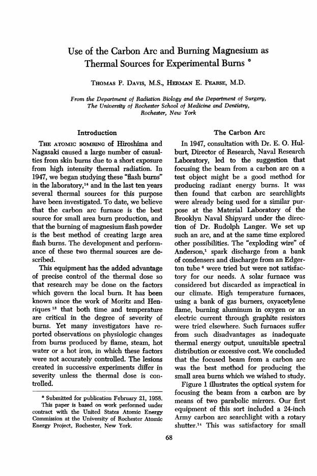
FIG. 7. A large carbonized flash burn of about 20 per cent body area produced byburming magnesium flash powder. Note the leathery eschar formed, which acts as animpervious covering to the lesion. The head, hooves and genitalia are protected toavoid unnecessary discomfort. This animal has been anesthetized for taking a biopsy.
The present blends are made to have an
ignition time of 0.3 to 2.0 sec., and if no
more than 200 cm. of powder are used,blast is not a problem. Some blast occurs
with a burning time of 0.3 sec. and becomesexcessive with times much below this.
Originally we mixed our own materialunder a hood by sifting the compoundsthrough 150-mesh screen, after which theywere blended, weighed and packaged. Thiswas both tedious and hazardous so arrange-
ments were made to purchase ready mixedpowder in 50 gram packages from Kilgore,Inc., of Waterville, Ohio. The average com-
position by weight of this material is:
Barium nitratePotassium nitrateMagnesium, Grade BAluminum, Grade A
40.5%13.5%19.0%27.0%
Calibration of Magnesuim Flash Pow-der: Radiometer measurements of the rateof energy released from a powder burningin 0.7 sec. show a curve of intensity whichrises sharply to a maximum at 0.2 sec. andthen falls more gradually to the base line.15
The general shape of this curve is not un-
like that of the radiant thermal energy fromthe fire ball of an atomic bomb.8A cone calorimeter developed by Davis 4
was used to measure the radiant energy in-cident at 15, 30, and 45 cm. from chargesof 50, 100, and 150 Gm. of the flash powder.Under these conditions measurementsshowed a range of 2 to 22 cal./cm.2 witha variation of 10 per cent. An exampleof a large area, carbonized bum caused byan exposure to 150 Gm. of magnesium flashpowder is shown in Figure 7.The severity of the burn may be assessed
by surface appearance and by its depth.Biopsies taken at 24 hours are stained bythe method, developed in this laboratory,"to give objective differentiation of the depthof burn in the dermis. Damage is measuredto the deepest point seen in the section bya micrometer in the eyepiece.
DiscussiornThe equipment described was developed
as a laboratory source of radiant thermal
74 Annals of SurgeryJanuary 1959

Volume 149 THERMAL SOURCES FOR EXPERIMENTAL BURNS 75Number 1
energy which would simulate, as accuratelyas possible, the thermal radiation fromatomic bomb explosions. This cannot beabsolute, for some of the characteristics ofbomb radiation are imperfectly understoodwhile others may vary from weapon toweapon. A useful laboratory source mustnot only reproduce the major characteristicsof the thermal energy from atomic weapons,but also permit the alteration of exposureparameters to allow simulation of the effectfrom atmospheric attenuation, distance andweapon yield. Thus the laboratory sourcemust be flexible in terms of flux density,spectral distribution and form and durationof the radiant pulse. However, this flexibil-ity cannot be achieved by sacrificing stabil-ity of calibration if reproducible results areto be attained.While the quality, form and duration of
atomic bomb radiation may be closely ap-proximated by laboratory equipment, it isprobable that it can never simulate the ex-posure geometry from actual weapons. Inour area of interest for thermal effects, thegeometry of bomb radiation corresponds tothat of a distant point source with conse-quent plane parallel radiation impingingupon the target. All surfaces of the receivernormal to the source will be uniformly ex-posed, and intervening objects will castsharp shadows, so commonly observed inJapan. This type of geometry cannot beduplicated in the laboratory.The carbon arc lamp gives a steady and
reproducible source of radiation. Accessoryequipment permits convenient, flexible andaccurate control of spectral distribution,form, and duration of exposure. Its disad-vantage is the limited size of a uniform ex-posure so that it can only be used to studysmall areas. Where the factors which modifythe severity of the local burn lesion are tobe evaluated, it is a highly precise tool andis the method of choice for carefully con-trolled quantitative work.
In situations where a large area of ex-posure is desired, we have found burning
magnesium flash powder to be a suitablesource. It is the only method devised todate for creating, in the laboratory, a largearea flash burn by conditions that are com-parable to those resulting from atomicweapons. The total energy delivered by thisincendiary is controlled by the amount ofmaterial ignited and the source-receiverdistance. Calorimetric studies indicate asurprisingly good reproducibility of thethermal energy delivered, with less than10 per cent variation from shot to shot. Thespectral distribution and form of the pulseare fixed by the characteristics of the flashpowder. Within these limitations, this sourceis very useful for large area radiant energyburn studies.As our investigations have continued we
have become increasingly interested in thefundamental physical and chemical changesthat enter into the production of cutaneousburns and how these modify the severity ofthe lesions. It is felt that only by such re-search will one arrive at some of the prac-tical answers that are needed. This has re-quired precision equipment. It is our opin-ion that the development of the thermalsources described has had the dual advan-tages of experimentally simulating bombradiation, and creating a laboratory tool forthe exploration of the mechanisms involvedin cutaneous burns.
Bibliography1. Anderson, J. A.: The Spectrum of Electrically
Exploded Wires. J. Astrophys., 51:37, 1920.2. Blakney, R. M., T. P. Davis, L. J. Krolak and
H. E. Pearse: Development of a CopperSphere Radiometer. Univ. of RochesterAtomic Energy Project Report, UR-152(1951).
3. Butler, C. P.: High Intensity Carbon ArcSources for Thermal Radiation Studies. U. S.Naval Radiological Defense Laboratory Re-port, USNRDL-453 (1955).
4. Davis, T. P.: A Standard Radiation Calorim-eter. Master's Thesis, The University ofRochester ( 1954).

76 ~~~~~~~~DAVIS AND PEARSE Annals of Surgery76VIS AND PEARSEJanuary 1959
5. Davis, T. P., L. J. Krolak, R. M. Blakney andH. E. Pearse: Modification of the CarbonArc Searchlight for Producing ExperimentalFlashbums. J. Optical Soc. America, 44:766,1954.
6. Edgerton, H. E.: Photographic Use of Elec-trical Discharge Flashtube. J. Optical Soc.America, 36:390, 1946.
7. Fauley, G. B. and A. C. Ivy: Prevention ofFlash Burns by a Protective Glove Film.U. S. Naval Med. Bull., 43:209, 1944.
8. Glasstone, S.: The Effects of Nuclear Weapons.U. S. Govt. Printing Office, 1957.
9. Hinshaw, J. R. and H. E. Pearse: HistologicTechnics for the Differential Staining ofBurned and Normal Tissues. Surg., Gynec.& Obst., 103:726, 1956.
10. Krolak, L. J. and T. P. Davis: A UniversalSpectrophotometer for the Measurement ofthe Relative Spectral Distribution of the Car-bon Arc Source. Univ. of Rochester AtomicEnergy Project Report, UR-367, 1954.
11. Mixter, G., Jr. and T. P. Davis: A Method ofShaping Thermal Energy Pulses from aCarbon Arc Source. Univ. of Rochester
Atomic Energy Project Report, UR-387,1955.
12. Monahan, T. I., L. Banet, G. E. Davis, M.Furst, R. Langer and J. M. McGreevy: ASource of Intense Thermal Radiation Involv-ing the Imaging of a High-intensity CarbonArc. Material Laboratory, New York NavalShipyard (to be published).
13. Moritz, A. R. and F. C. Henriques: Studiesof Thermal Injury. II. The Relative Impor-tance of Time and Surface Temperature inthe Causation of Cutaneous Bums. Am. J.Path., 23:695, 1947.
14. Pearse, H. E., J. T. Payne and L. Hogg: TheExperimental Study of Flash Burns. Ann.Surg., 130:774, 1949.
15. Roth, R. E., H. W. Bales and H. E. Pearse: AMethod for the Safe Firing of MagnesiumPowder to Produce Large Area Flash Burns.Univ. of Rochester Atomic Energy ProjectReport, UR-435, 1956.
16. Schmidt, F. H., R. C. Williams, W. T. Ham,Jr., J. W. Brooks and E. I. Evans: Experi-mental Production of Flash Bums. Surgery,36:1163, 1954.