Embed Size (px)
Citation preview

499
USE OF PHASED ARRAY ULTRASONIC EXAMINATION IN LIEU OF RADIOGRAPHY
AT THE POINT BEACH NUCLEAR PLANT
Todd Blechinger / Jeff Devers
Lambert, MacGill, Thomas, Inc
San Clemente, California USA
William A. Jensen
NextEra Energy Resources Point Beach, LLC
Two Rivers, Wisconsin USA
ABSTRACT
Replacement of piping during a nuclear plant refueling outage is an expensive and time-consuming
project, and the typical means of accepting construction welds is radiography (RT). This paper will
address the planning, preparation, execution, and lessons learned by both utility and vendor personnel
during a series of the Point Beach Nuclear Plant’s (PBNP) refueling outages where phased array ultrasonic
(PA-UT) examinations were used in lieu of RT, thus saving hundreds of hours of down-time.
BACKGROUND
Many nuclear power plants in the United States have gone through both plant life-extension/license
renewal and Extended Power Uprate (EPU) projects. In a number of cases, a sizable amount of piping
systems, structures, and components are determined to require replacement to either (a) meet the increased
flow of Power Uprate conditions or (b) meet the end-of-extended-license (EEL) requirements. Because of
this, as well as the cost in outage “critical path” time (typically >$500,000 USD/day), anything that can
allow work to occur concurrently can, in the long term save time/money over conventional methods of
accepting construction piping welds, such as RT.
POINT BEACH SPECIFICS
Point Beach Nuclear Plant (PBNP) is located approximately 30 miles southeast of Green Bay, Wisconsin
and has been owned and operated by NextEra Energy Resources since September, 2007. PBNP consists of
two (2) Units, both Westinghouse-designed, 132 inch (335.28 cm) inside diameter (ID) two-loop PWR’s.
Both units were designed and built in the mid- to late 1960’s and were some of the earliest PWR’s in the
United States to commence commercial operation. In 2008, NextEra embarked upon an ambitious
program to perform an Extended Power Uprate to each unit, to increase capacity by approximately 17%,
which required replacement of all five (5) feedwater heaters on each train, as well as a large amount of
piping. This piping was of various diameters and thicknesses, ranging from 1 inch (2.54 cm) to 20+ inch
(50+ cm).
DETERMINATION OF THE NEED FOR UT IN LIEU OF RT
In the Summer of 2008, the PBNP NDE Level III was performing reviews of the EPU work scope for the
Fall 2008 outage (Unit 1, Refueling 30) and noted several items:
• The work scope included a number of large-bore, heavy-walled piping welds which would
require volumetric examination (typically RT) for final acceptance in accordance with ASME/ANSI
B31.1, “Power Piping.”
• The year chosen for the piping replacement code (2004 Edition, no Addenda) allowed the use
of either ultrasonic or radiographic examination for final weld acceptance.
• The location of a number of the piping welds were such that a major impact on the overall
outage schedule could be anticipated if RT was chosen.

500
The PBNP NDE Level III felt that these items added up to “the perfect storm” for a reasoned
argument to use Phased Array UT in lieu of RT. Unfortunately, there were several factors working against
the idea, including some bad experiences at other NextEra Energy nuclear facilities when using UT in lieu
of RT as well as the implied “high cost” of UT. However, after a number of discussions with various
personnel both at site and at NextEra headquarters in Florida, the installation vendor agreed to contract
Lambert, MacGill, Thomas (LMT) who is the PBNP ASME Section XI NDE vendor to perform the work.
The use of LMT benefited both the installation vendor and the site, since a number of the LMT personnel
had previous experience at PBNP and knew the procedures and processes, as well as the ability to use
them on other non-EPU work when EPU work was slow or non-existent.
EXAMINATION EQUIPMENT SPECIFICS
LMT utilized the Zetec Omniscan™ 32P-32R system with software version 1.3R16 or 1.1R0 for data
acquisition, which was coupled with a custom-built hand scanner for the first several EPU projects. The
hand scanner was later replaced by a semi-automated motorized scanner which was also fabricated by
LMT (Figure 1). The transducers used were GE Inspection Technologies (GEIT) 2-D Matrix-Array
nominal frequency of 3.5 MHz or 5.0 MHz. The Arrays were Dual Pitch/Catch 16x2 element Matrix
Arrays containing rectangular shaped elements with a Primary Axis pitch of 0.85 mm and a Secondary
Axis Pitch of 2.75 mm. The frequencies were chosen based on the best responses from implanted flaws in
mock-ups. The analysis was performed using UltraVision® software. The work was controlled by a Point
Beach NDE procedure (NDE-142: Fully Encoded Phased Array Ultrasonic Examination of Ferritic Piping
Welds) and the Point Beach Work Order process.
Figure 1
Semi-Automated Scanner Used for 2011 Examinations
501
Unit 1 Refueling 31 (Fall 2008)
In late August, 2008, after numerous discussions with the PBNP NDE Level III regarding UT versus RT;
the installation vendor issued a contract to LMT to provide PA-UT services for U1R30, which was
scheduled to start approximately five (5) weeks later. Due to the long lead-time required to procure
special arrays and wedges, the PBNP NDE Level III had provided information to LMT to start the work
planning. In addition, the LMT Level III responsible for their PA program began working with PBNP to
develop a new procedure and a regimen for demonstration to the Authorized Inspector (AI). The work
scope for U1R31 included approximately forty (40) sixteen-inch (40.6 cm) and eighteen-inch (45.7 cm)
piping welds for the #4 and #5 Feedwater heaters. These heaters are located within approximately 40 feet
(12.2 meters) of the entrance to the Radiation Controlled Area (RCA) and within 10-30 feet (3 – 9.1
meters) of two major foot-traffic routes (Figure 2). If RT had been performed on these, the impact would
have been enormous, since all entry/exit to the RCA would have been interrupted for literally hours at a
time. PBNP personnel estimated that the delays for RT on the 40 welds would be upwards of 2.5 days (5,
12-hour shifts).
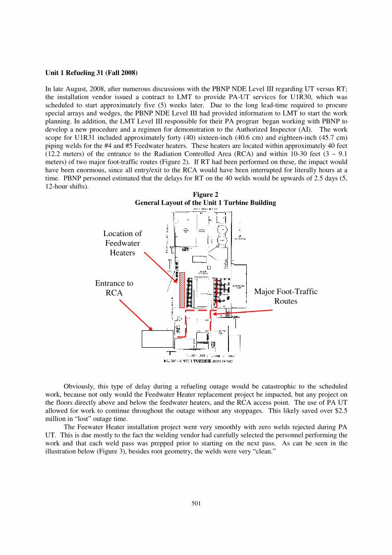
Figure 2
General Layout of the Unit 1 Turbine Building
Obviously, this type of delay during a refueling outage would be catastrophic to the scheduled
work, because not only would the Feedwater Heater replacement project be impacted, but any project on
the floors directly above and below the feedwater heaters, and the RCA access point. The use of PA UT
allowed for work to continue throughout the outage without any stoppages. This likely saved over $2.5
million in “lost” outage time.
The Feewater Heater installation project went very smoothly with zero welds rejected during PA
UT. This is due mostly to the fact the welding vendor had carefully selected the personnel performing the
work and that each weld pass was prepped prior to starting on the next pass. As can be seen in the
illustration below (Figure 3), besides root geometry, the welds were very “clean.”
Location of
Feedwater
Heaters
Entrance to
RCA Major Foot-Traffic
Routes

502
Figure 3
Typical View of a Completed Weld
Unit 2 Refueling 30 (Fall 2009)
In August, 2009, the PBNP NDE Level III had to go through a similar set of arguments to perform a
similar work scope for Unit 2. This was due mostly to the replacement of the installation vendor with a
new vendor. This vendor had NDE personnel on staff who were very supportive of the idea, but were not
so supportive of the use of the PBNP-recommended vendor. Again, after a number of discussions with the
installation vendor and EPU personnel, LMT was awarded a contract for the work, which proceeded with
no problems from an AUT standpoint and only one repair out of approximately 35 welds.
U2R31 – Continued Success
In March 2011, U2R31 commenced. By this point, PBNP EPU management had determined that the use
of PA-UT was worth what appeared at face-value to be an additional expense. This outage included PA-
UT of several welds in the façade area (an unheated building around the containment building), which
presented some challenges due to the typical Wisconsin “spring” weather with temperatures down to 10°
to 15°F (-12° to -9°C)at night, as well as LMT personnel having to work in close proximity to both
welding and heat-treating activities. The majority of the piping was concentrated around the replacement
main feedwater pumps, which are located in the basement of the Turbine Building. The pipe replacement
was extremely complex due to the design of the new pumps compared to the old ones, which caused the
overall project to be almost two months behind the original schedule however, none of the delays were
attributed to the PA-UT. All welds passed final UT with no repairs and Unit 2 re-started in June 2011 at
the new output of approximately 624 MWe (17% uprate).

503
U1R33 –Final Exams
In October 2011, U1R33, the final outage of the EPU series commenced. This outage also included PA-
UT of several welds in the façade area, but the work was completed during a relatively warm fall season
with the remainder of the welds located around the Unit 1 replacement main feedwater pumps. The
installation vendor applied the many lessons learned from U2R31, and the project was completed
essentially right on schedule. The final weld passed PA-UT on Friday, November 25th (the day after
Thanksgiving). Again, all welds passed final UT with no repairs.
CONCLUSIONS
The use of PA-UT in lieu of radiography for ASME/ANSI B31.1 piping is an extremely cost-effective
solution. When planning to perform PA-UT in lieu of RT, and number of items should be considered:
1. The installation vendor should work hand-in-hand with the NDE vendor, however, it was
found to be more efficient to have site NDE personnel responsible for both contract management and day-
to-day direction instead of having the PA-UT vendor work for the installation vendor, but report to the
NDE Level III.
2. The vendor should be considered a team member and not treated as someone who will just
show up, do a job, and leave. Communication to vendor personnel by the site should occur frequently and
they should understand how important their job is to the overall success of the outage, as well as the future
of the plant.
3. Site project personnel should become intimately familiar with the equipment, procedures, and
processes so that when challenges arise, they can understand some of the bases for recommendations that
may come from the vendor.
THANKS
The authors would like to thank the following individuals and or groups for their support over the
Extended Power Uprate Project:
Hartford Steam Boiler Insurance and Inspection Company:
Mr. Jeffrey Bukowiecki
NextEra Energy - Point Beach Nuclear Plant:
Messrs. Roger Bardo, Steve Brown, Wayne Groeschel, Fred Hueber and Charlie Trezise.
REFERENCES
1) American Society of Mechanical Engineers (ASME) Boiler and Pressure Vessel Code, Section V,
2004 Edition ASME, New York, New York, 2004.
2) ASME / ANSI B31.1, “Power Piping”, 2004 Edition, ASME, New York, New York, 2004.