Embed Size (px)
Citation preview
Summary The objectives of our study were to assess the fea-sibility of using ground-penetrating radar (GPR) to study rootsover a broad range of soil conditions in the southeastern UnitedStates. Study sites were located in the Southern Piedmont,Carolina Sandhills and Atlantic Coast Flatwoods. At each site,we tested for selection of the appropriate antenna (400 MHzversus 1.5 GHz), determined the ability of GPR to resolve rootsand buried organic debris, assessed root size, estimated rootbiomass, and gauged the practicality of using GPR. Resolutionof roots was best in sandy, excessively drained soils, whereassoils with high soil water and clay contents seriously degradedresolution and observation depth. In the Carolina Sandhills,16 1 × 1-m plots were scanned with the 1.5 GHz antenna usingoverlapping grids. Plots were subsequently excavated, largerroots (> 0.5 cm diameter) sketched on graph paper beforeremoval, and all roots oven-dried, classified by size andweighed. Roots as small as 0.5 cm in diameter were detectedwith GPR. We were able to size roots (0.5 to 6.5 cm in diame-ter) that were oriented perpendicular to the radar sweep (r 2 =0.81, P = 0.0004). Use of image analysis software to relate themagnitude of radar parabolas to actual root biomass resulted insignificant correlations (r 2 = 0.55, P = 0.0274). Orientation andgeometry of the reflective surface seemed to have a greater in-fluence on parabola dimensions than did root size. We con-clude that the utility of current GPR technology for estimatingroot biomass is site-specific, and that GPR is ineffective insoils with high clay or water content and at sites with rough ter-rain (most forests). Under particular soil and site conditions,GPR appears to be useful for augmenting traditional biomasssampling.
Keywords: GPR, map roots, noninvasive, radar antenna, ra-dar profile, reflector, root biomass, root biomass assessment,root biomass sampling, root detection.
Introduction
Premise
Ground-penetrating radar (GPR) has proved to be a usefulgeophysical tool for the detection and characterization of fea-tures buried within the shallow subsurface (0.25 to 1.5 m
depth). This rapid and noninvasive technique has been used tolocate buried artifacts (Conyers and Goodman 1997), draintiles (Chow and Rees 1989), anti-personnel mines (Bruschiniet al. 1998, Daniels 1998), and pipes and cables (Ulriksen1982, Daniels 1996).
Although roots have commonly been observed in soil pro-files (Bevan 1984, Truman et al. 1988, Farrish et al. 1990), theyhave often been considered an unwanted source of noise thatcomplicates radar interpretation (Doolittle and Miller 1991,Barker and Doolittle 1992). Recently, GPR was used to map thecoarse (> 3 cm diameter) root system of 50-year-old sessile oak(Quercus petraea Mattl.) trees (Hruska et al. 1999). Typically,coarse tree roots have been measured by destructive excava-tion of the root system, an extremely labor-intensive endeavor.Because of its noninvasiveness, suitable depth range and reso-lution, Hruska et al. (1999) considered GPR to be an appropri-ate tool for the measurement of coarse root systems.
Ground-penetrating radar principles
Ground-penetrating radar is an impulse radar system designedfor shallow, subsurface investigations (Morey 1974, Ulriksen1982, Daniels 1996). The system transmits short pulses ofelectromagnetic energy into the ground from an antenna. Eachpulse consists of a spectrum of frequencies distributed aroundthe central frequency of the transmitting antenna. Whenever apulse contacts an interface separating layers of differing elec-tromagnetic properties, a portion of the energy is reflectedback to a receiving antenna. The receiving unit amplifies andsamples the reflected energy and converts it into a similarlyshaped waveform in a lower frequency range. The processedreflected waveforms are displayed on a video screen or storedon a disk for later playback, processing or printing.
The system radiates energy in an elliptical cone of diver-gence and scans a footprint area beneath the antenna (Annanand Cosway 1994, Conyers and Goodman 1997). Because theantenna’s radiation pattern forms an elliptical cone of diver-gence, small features are sensed before and after the antenna ismoved directly over them. Because of the initially decreasingand then increasing travel time to a subsurface reflector, smallsubsurface features, such as roots, often produce hyperbolicpatterns (Barker and Doolittle 1992). These hyperbolas are
Tree Physiology 21, 1269–1278© 2001 Heron Publishing—Victoria, Canada
Use of ground-penetrating radar to study tree roots in the southeasternUnited States
J. R. BUTNOR,1 J. A. DOOLITTLE,2 L. KRESS,1 S. COHEN1 and K. H. JOHNSEN1
1 Southern Research Station, USDA Forest Service, 3041 Cornwallis Road, Research Triangle Park, NC 27709, USA2 USDA-NRCS, 11 Campus Boulevard, Suite 11, Newtown Square, PA 19073, USA
Received January 31, 2001
Dow
nloaded from https://academ
ic.oup.com/treephys/article/21/17/1269/1669380 by guest on 16 February 2022

readily observable on radar profiles and can aid interpretation.The apex of a hyperbola will occur when the antenna is di-rectly over a root. Other linear features, such as buried pipesand drainage tiles, produce visible hyperbolas only whencrossed at a traverse line angle greater than 45° (Chow andRees 1989, Roberts and Daniels 1993). However, whencrossed at angles of less than 45°, these features produce im-ages that are elongated, obscured and more difficult to distin-guish. These observations also apply to roots.
The footprint area “illuminated” by the radar is consideredan elliptical cone and can be approximated by the formula(Conyers and Goodman 1997):
A D e= + +λ / / ,4 1 (1)
where A is radius of the footprint area at depth D, λ is the cen-tral frequency wavelength of the antenna, and e is the dielec-tric permittivity of the scanned materials. According to Equa-tion 1, the footprint area varies directly with the wavelength ofthe antenna (Conyers and Goodman 1997). Higher frequencyantennae have shorter wavelengths (time to complete signalwaveform) and will provide a smaller or more focused foot-print area than lower frequency antennae. Also, the higher thedielectric permittivity of the profiled material, the smaller theilluminated footprint area (Conyers and Goodman 1997).Therefore, wetter soil conditions should result in a more con-tracted cone of radiation.
Because of the antenna’s comparatively broad beam, ob-jects that are located at some distance from either side of theantenna track can be sensed (Conyers and Goodman 1997).Typically, these objects will have lower amplitudes than simi-lar objects that occur directly beneath the path of the antenna.In addition, because of longer pulse travel times to these offsetreflectors, they will appear in radar profiles to lie deeper thantheir actual depths.
Resolution refers to the ability to discriminate between twoclosely spaced features, as well as the minimum size detect-able. Resolution increases with decreasing wavelength (Dan-iels 1996). Therefore, high-frequency antennae provide higherresolution than low-frequency antennae.
The objectives of this study were to expand on the work ofHruska et al. (1999) and to assess the feasibility of using GPRfor field research in the southeastern United States. We exam-ined the ability of GPR to delineate roots under a range of soilconditions and to estimate root diameter, and assessed the rel-ative utility of two antennae. We also tested the ability of GPRto detect nutritional treatment differences in root biomass in areplicated field experiment on a sandy site.
Materials and methods
Radar equipment
We used the Subsurface Interface Radar (SIR) System-2000,manufactured by Geophysical Survey Systems, Inc. (NorthSalem, NH). The SIR System-2000 consists of a digital con-trol unit (DC-2000) with keypad, VGA video screen, and con-
nector panel. We used Model 5100 (1.5 GHz) and 5103(400 MHz) antennae, which have a bow-tie dipole configura-tion. This system is backpack portable, is powered by a 12-VDC battery and, with an antenna, typically requires two peopleto operate. Scanning times used in this study ranged from 10 to40 ns and depended on site conditions. Daniels (1996) dis-cusses radar systems and principals of operation.
The radar profiles were processed through the WINRADsoftware package (Geophysical Survey Systems, Inc.). Pro-cessing was limited to signal stacking, horizontal scaling,color transforms and table customizing. Color transformationand table customization reduced background noise.
The radar unit was calibrated at each study site before use.To determine an approximate depth scale, a metallic calibra-tion disk was buried in the ground at each site, at a depth of40 to 50 cm. The known depth and two-way pulse travel timeto this interface provided a means to estimate the velocity ofpropagation and to depth-scale the radar imagery. These esti-mates were later adjusted, if needed, based on measureddepths and two-way travel times to roots that had been de-tected with GPR and excavated.
Ground-penetrating radar discrimination of roots in varioussoils
Soil properties have the potential to limit GPR penetration. Tostudy a range in soils typical of the southeastern United States,sites were selected in the Atlantic Coast Flatwoods, Georgiaand Carolina Sandhills, and Southern Piedmont Major LandResource Areas (MLRA) (Austin 1965). Selected sites en-compassed a variety of textural and drainage classes. At eachsite, the radar unit was calibrated and test transects were estab-lished and scanned with both the 1.5 GHz and 400 MHz anten-nae. The resulting waveform diagrams were printed and allpoint reflectors were identified visually. Select putative loca-tions (where point reflectors were observed) were excavatedand any roots observed were measured. Areas where no pointreflectors were observed were also excavated to determine ifundetected roots were present. The velocity of propagationand the effective depth of penetration for each antenna weredetermined at each site. Logistical considerations of workingin recently harvested sites, young forests and end-of-rotationforests were noted.
Atlantic Coast Flatwoods MLRA Atlantic Coast Flatwoodsconsist primarily of poorly drained to excessively drained soilsformed in eolian and marine sediments. Relief is typically lessthan a few feet, but as much as 20 feet along stream valleys(Austin 1965). Sites with contrasting soils were selected.
(1) Lakeland soil. The site was located near Olar, SouthCarolina, within an eastern cottonwood (Populus deltoidesBartr.) plantation. Deep, excessively drained, rapidly perme-able Lakeland soil formed in thick beds of eolian or marinesands. The soil is a member of the thermic, coated TypicQuartzipsamments family (Soil Survey Staff 1999). Lakelandsoils have limited profile development. All horizons are sandor fine sand with less than 10% silt and clay. The ground sur-face was relatively free of debris and litter.
1270 BUTNOR, DOOLITTLE, KRESS, COHEN AND JOHNSEN
TREE PHYSIOLOGY VOLUME 21, 2001
Dow
nloaded from https://academ
ic.oup.com/treephys/article/21/17/1269/1669380 by guest on 16 February 2022

(2) Lynchburg soil. The study site was located near MoncksCorner, South Carolina. The deep, somewhat poorly drainedsoil formed in loamy marine sediments. Lynchburg soil is amember of the fine-loamy, siliceous, semiactive, thermicAeric Paleaquults family (Soil Survey Staff 1999). The soilhas higher water and clay content and greater profile develop-ment than Lakeland soil. Lynchburg soil has a subsoil with asmuch as 30% silt and clay. It is somewhat poorly drained witha water table that is seasonally within depths of 60 cm. Contentof coarse fragments ranges from 0 to 7%. Two adjacent siteswere selected. The first was in an area that had been harvested4 years ago and replanted with loblolly pine (Pinus taeda L.)2 years ago. The site was bedded and old stumps were stillpresent. The second site was a 25-year-old loblolly pine plan-tation that had been recently burned of undergrowth.
Georgia and Carolina Sandhills MLRA The study site wasat the USDA Forest Service Southeast Tree Research and Edu-cational Site (SETRES) in Scotland County, North Carolina.The site supported a 15-year-old loblolly pine plantation onWakulla soil. This deep, excessively drained, rapidly perme-able soil formed in sandy Coastal Plain sediments on uplands.Wakulla soil is a member of the sandy, siliceous, thermicPsammentic Hapludults family (Soil Survey Staff 1999). In atypical profile, Wakulla soil contains about 85 to 92% sand and8 to 15% silt and clay. This coarse-textured soil has low or-ganic matter content and low water-holding capacity.
Southern Piedmont MLRA Two sites were selected in theDuke Forest near Durham, North Carolina, in areas of Applingand Georgeville soils. Transects were scanned in 70-year-oldloblolly pine plantations. These deep, well-drained, moder-ately permeable soils formed in residuum on uplands, and havea fine-textured (> 35% clay) subsoil that is composed predomi-nantly of clays with a low cation exchange capacity. Applingsoil is a member of the fine, kaolinitic, thermic Typic Kan-hapludults family (Soil Survey Staff 1999). Coarse fragmentsrange from 0 to 35% by volume in the surface layer and 0 to10% in the subsoil. Georgeville soil is a member of the fine,kaolinitic, thermic Typic Kanhapludults family (Soil SurveyStaff 1999). Coarse fragments range from 0 to 20% by volumein the surface layer and 0 to 10% in the subsoil.
Use of GPR to estimate root size and biomass and to maptree root systems
Root sizing with GPR An attempt was made to delineate treeroot size by GPR under optimal conditions. Roots 3–4 m longthat were 5–7 cm thick at one end and tapered to 0.5 cm wereexcavated and placed in shallow trenches. Root diameters weremeasured and survey flags were used to mark the position ofeach diameter along the trench wall. The roots were reburiedin the trenches and scanned with the 1.5 GHz antenna.(Compared with the 1.5 GHz antenna, the 400 MHz antennawas found to have a lower capacity to resolve roots across thevarious soil types and was not used for root sizing or biomassassessment.) Scans were completed perpendicular to the longaxis of the trench and the buried root. This allowed scanning of
a radial “slice” that would provide the best opportunity to esti-mate root diameter. The buried root test was performed at theGeorgia and Carolina Sandhills site (Wakulla soil) with a lob-lolly pine root and at the Atlantic Coast Flatwoods sites (Lake-land soil) with an eastern cottonwood root. The loblolly pineroot was buried at two trench depths (15 and 30 cm) at theGeorgia and Carolina Sandhills site. At the Atlantic Coast Flat-woods site, the trench was 20 cm deep.
The qualitative imagery on radar profiles was converted toquantitative data by Optimas image analysis software (Ver-sion 5.1a, Optimas Corporation, Seattle, WA). The programcalculated the relative area (cm2) of high amplitude reflectionthat met a threshold luminescence. A minimum and maximumthreshold of 40 and 130 units, respectively, were used becausethey were found to provide the best balance between back-ground noise reduction and discrimination of roots from thesoil matrix. These settings are subjective and specific to thesoftware package. Some profiles contained reflections fromthe trench wall that gave false signals. These reflections wereseparated with image analysis software and subtracted fromthe total area. Pearson’s correlation coefficient between thehigh amplitude area and root diameter was calculated (SASSystem Version 8.01, SAS Institute, Cary, NC).
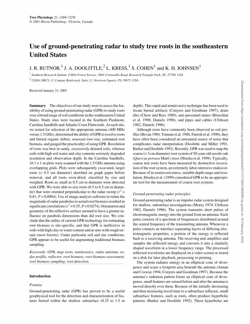
Root biomass assessment Root biomass studies commencedat SETRES in the Georgia and Carolina Sandhills MLRA.SETRES is a 2 × 2 factorial experiment of fertilization and irri-gation with four replications in a loblolly pine plantationplanted in 1985 with 2 × 3-m spacing. Seven years of fertiliza-tion have increased coarse root biomass relative to controls(Albaugh et al. 1998). The fertilization component of the exist-ing study was used to test the ability of GPR to assess root bio-mass because it provided a wide range of rooting densities.Within each replication, two subplots were selected in the con-trol treatment and two in the fertilization treatment for a total offour subplots per replication and a total of 16 for the entirestudy. In each subplot, 1 × 1-m grids were established to thenorthwest of a tree (Figure 1). Each grid was composed of foureast–west and four south–north radar transects. The transectsthat comprised the grid were 25 cm apart. Each transect wasmade by pulling the 1.5 GHz antenna along the grid line illus-trated in Figure 1 at a constant speed.
Radar profiles were assessed by two independent means:manual reflector counts that tally the number of high ampli-tude reflections suspected to be tree roots, and area of highamplitude luminescence analyzed with the Optimas imageanalysis software. The grids were later methodically harvestedto depth classes of 0–20 and 20–40 cm. All roots greater than0.5 cm in diameter were sketched on graph paper. The rootswere sieved, separated into size classes (0–2, 2–5 and > 5 mmdiameter) and further subdivided into live and dead roots. Allroots were oven dried at 65 °C for 7 days and weighed.
Manual reflector counts and high amplitude area derivedfrom each radar pass were correlated to actual root biomassharvested directly below each pass. Data from all eight radarpasses in each grid were composited and correlated to the totalroot biomass of the entire grid for the 0–20, 0–40 and 20–
TREE PHYSIOLOGY ONLINE at http://heronpublishing.com
STUDY OF TREE ROOTS WITH GROUND-PENETRATING RADAR 1271
Dow
nloaded from https://academ
ic.oup.com/treephys/article/21/17/1269/1669380 by guest on 16 February 2022
40 cm depth intervals. Effects of fertilization on root biomassand the two index variables, i.e., reflector tally and high ampli-tude area, were evaluated by analysis of variance performedwith the SAS statistical software package (Proc ANOVA, SASSystem Version 8.01, SAS Institute).
Results
Ground-penetrating radar discrimination of roots in varioussoils
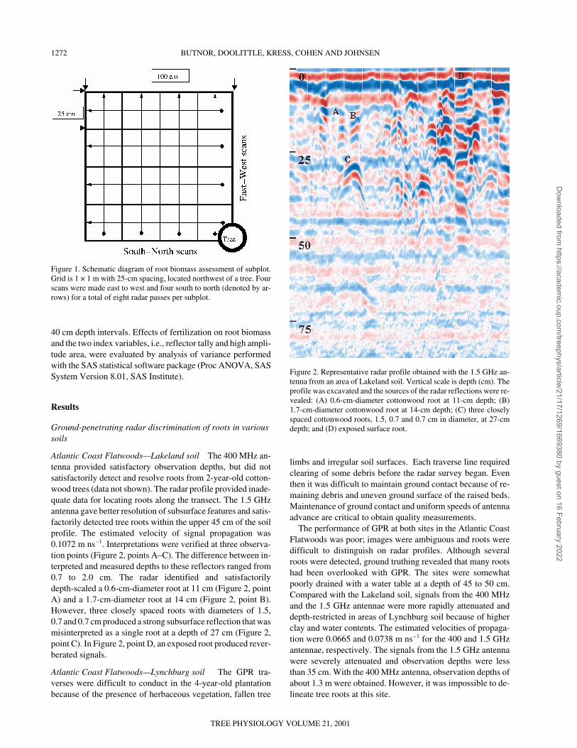
Atlantic Coast Flatwoods—Lakeland soil The 400 MHz an-tenna provided satisfactory observation depths, but did notsatisfactorily detect and resolve roots from 2-year-old cotton-wood trees (data not shown). The radar profile provided inade-quate data for locating roots along the transect. The 1.5 GHzantenna gave better resolution of subsurface features and satis-factorily detected tree roots within the upper 45 cm of the soilprofile. The estimated velocity of signal propagation was0.1072 m ns–1. Interpretations were verified at three observa-tion points (Figure 2, points A–C). The difference between in-terpreted and measured depths to these reflectors ranged from0.7 to 2.0 cm. The radar identified and satisfactorilydepth-scaled a 0.6-cm-diameter root at 11 cm (Figure 2, pointA) and a 1.7-cm-diameter root at 14 cm (Figure 2, point B).However, three closely spaced roots with diameters of 1.5,0.7 and 0.7 cm produced a strong subsurface reflection that wasmisinterpreted as a single root at a depth of 27 cm (Figure 2,point C). In Figure 2, point D, an exposed root produced rever-berated signals.
Atlantic Coast Flatwoods—Lynchburg soil The GPR tra-verses were difficult to conduct in the 4-year-old plantationbecause of the presence of herbaceous vegetation, fallen tree
limbs and irregular soil surfaces. Each traverse line requiredclearing of some debris before the radar survey began. Eventhen it was difficult to maintain ground contact because of re-maining debris and uneven ground surface of the raised beds.Maintenance of ground contact and uniform speeds of antennaadvance are critical to obtain quality measurements.
The performance of GPR at both sites in the Atlantic CoastFlatwoods was poor; images were ambiguous and roots weredifficult to distinguish on radar profiles. Although severalroots were detected, ground truthing revealed that many rootshad been overlooked with GPR. The sites were somewhatpoorly drained with a water table at a depth of 45 to 50 cm.Compared with the Lakeland soil, signals from the 400 MHzand the 1.5 GHz antennae were more rapidly attenuated anddepth-restricted in areas of Lynchburg soil because of higherclay and water contents. The estimated velocities of propaga-tion were 0.0665 and 0.0738 m ns–1 for the 400 and 1.5 GHzantennae, respectively. The signals from the 1.5 GHz antennawere severely attenuated and observation depths were lessthan 35 cm. With the 400 MHz antenna, observation depths ofabout 1.3 m were obtained. However, it was impossible to de-lineate tree roots at this site.
1272 BUTNOR, DOOLITTLE, KRESS, COHEN AND JOHNSEN
TREE PHYSIOLOGY VOLUME 21, 2001
Figure 2. Representative radar profile obtained with the 1.5 GHz an-tenna from an area of Lakeland soil. Vertical scale is depth (cm). Theprofile was excavated and the sources of the radar reflections were re-vealed: (A) 0.6-cm-diameter cottonwood root at 11-cm depth; (B)1.7-cm-diameter cottonwood root at 14-cm depth; (C) three closelyspaced cottonwood roots, 1.5, 0.7 and 0.7 cm in diameter, at 27-cmdepth; and (D) exposed surface root.
Figure 1. Schematic diagram of root biomass assessment of subplot.Grid is 1 × 1 m with 25-cm spacing, located northwest of a tree. Fourscans were made east to west and four south to north (denoted by ar-rows) for a total of eight radar passes per subplot.
Dow
nloaded from https://academ
ic.oup.com/treephys/article/21/17/1269/1669380 by guest on 16 February 2022

Georgia and Carolina Sandhills MLRA The ability of GPRto detect tree roots was exceptional in this area of Wakulla soil.A calibration transect was scanned with both antennae. Thetransect began in a cleared area, where a metallic calibrationdisk was buried, and moved into a loblolly pine plantation, go-ing from an area of low root density to an area of high root den-sity. Figures 3 and 4 are representative radar profiles obtainedwith the 400 and 1.5 GHz antennae, respectively. The velocityof propagation was 0.1070 and 0.1320 m ns–1 for the 400 and1.5 GHz antennae, respectively. The dashed, vertical whitelines at the top of each radar profile are event markers spaced atan interval of about 30 cm. The metallic calibration disk, bur-ied at a depth of about 48 cm, is evident to the immediate rightof “A” in each profile.
Compared with the 400 MHz antenna, the 1.5 GHz antennaprovided greater resolution of the upper 50 cm of the soil pro-file, and a greater number of point reflectors (roots) were dis-tinguishable (cf. Figures 3 and 4). In Figure 4, reflectors areconcentrated within the upper soil profile above a depth ofabout 30 cm. These reflectors are more numerous in the right-
hand portion of both Figures 3 and 4 where the transect wentfrom a clearing into a pine plantation. In this portion of the ra-dar traverse, the antenna passed several trees with many rootsin the upper 30 cm. Radar interpretations were confirmed byexcavating several small soil pits. In these excavations, rootswere encountered at anticipated depths. Roots as small as0.5 cm in diameter were detected with the 1.5 GHz antenna.
Despite excellent live root detection at this site, dead rootsdid not produce quality images. Dead, decaying roots < 5 cmin diameter were undetectable, as were remnants of taprootsfrom the previous forest stand (17- to 20-year-old).
Southern Piedmont MLRA Radar signals were rapidly atten-uated by the high clay contents of both the Appling andGeorgeville soils, and observation depths were restricted.Coarse fragments are common in these soils and their reflec-tions were similar to and easily confused with those of roots. Inareas of Appling soils, with the 1.5 GHz antenna, parallel bandsof background noise caused by high gain settings obscuredsome reflectors. The maximum profiling depth was about
TREE PHYSIOLOGY ONLINE at http://heronpublishing.com
STUDY OF TREE ROOTS WITH GROUND-PENETRATING RADAR 1273
Figure 3. Representative radar profile obtained with the 400 MHz an-tenna from an area of Wakulla soil. Vertical scale units are cm. Whitevertical lines at the top of the profile are 30 cm apart. Point “A” de-notes the location of the metal calibration disk.
Figure 4. Representative radar profile obtained with the 1.5 GHz an-tenna from the same area of Wakulla soil shown in Figure 3. Verticalscale units are cm. Point “A” denotes the location of the metal calibra-tion disk.
Figure 5. Composite radar profile of a loblolly pine root buried in a 15-cm-deep trench. Root diameter (cm) is shown above each reflection. All ra-dar passes were made perpendicular to the root in order to image a radial “slice.”
Dow
nloaded from https://academ
ic.oup.com/treephys/article/21/17/1269/1669380 by guest on 16 February 2022

60 cm. The estimated velocity of propagation was 0.1176 mns–1. Numerous point reflectors were detected within the upper30 cm of the soil profile. These point reflectors representedboth rock fragments and roots. The radar profiles producedwith the 1.5 GHz antenna were of modest interpretative value.High amplitude, low-frequency background noise producedhorizontal bands that partially masked reflections from pointanomalies, many of which were likely roots. Even after signalprocessing, the profile was ambiguous.
The 400 MHz antenna provided a profiling depth of about1 m, with more contrast and less ambiguous images of large(> 3.7-cm diameter) roots. The estimated velocity of propaga-tion was 0.1005 m ns–1. Large roots were correctly interpretedand observed in four of six pits at the estimated depths. Rootswith diameters of 10, 7.4 , 7.0 and 3.7 cm were distinguished.However, in the other two pits, coarse rock fragments were ob-served at depths that, in the field, were interpreted to containroots. Although some larger roots (3.7 to 10 cm in diameter)were detected with the 400 MHz antenna, smaller roots werenot detected.
The utility of GPR to estimate root size and biomass and tomap tree root systems
In the sandy, excessively drained soils at the Georgia andCarolina Sandhills MLRA, GPR successfully estimated rootdiameter of the loblolly pine root at both the 15 and 30 cmdepths. A composite radar profile created from 14 perpendicu-lar scans across the test trench is presented for the 15 cm depthin Figure 5. The center of the scan, where the root should be, ismarked with a white dotted vertical line. The reflected parab-ola near the centerline is the root. Areas of high amplitudereflection minus the false multiple reflections were closelycorrelated with root diameter (Figures 6A and 6B). The rela-tionship was highly significant at a depth of 15 cm, but de-clined with increasing depth. The upper parts of the Lakelandand Wakulla soil profiles are similar. They are comprised pri-marily of coarse sand, which is ideally suited to GPR. Cotton-wood roots as small as 0.5 cm in diameter were detectable withGPR. However, high amplitude reflections did not correlatewell with root diameter (Figure 7). Comparing Figures 6A and6B to Figure 7, it is apparent that the correlation between treeroot diameter and areas of high amplitude reflection variedwith soil depth and tree species.
Root biomass assessment For each of the 64 radar passes,high amplitude area and reflector tally were correlated to theobserved root biomass directly below it. Both of the radar vari-ables accounted for approximately one third of the variation inroot biomass (Table 1). When the entire plot was scanned anddata from the four passes that were conducted in the same di-rection were combined, the correlation improved markedly(Table 1). Combining the south to north and east to west datafor each plot further improved the correlation. The compositeof all passes in a plot gave the best correlation. High amplitudearea and reflector tally are directly proportional to changes inroot biomass (Figure 8).
Radar profiles were separated into depth classes of 0–20
and 20–40 cm and tested to determine if high amplitude areacould distinguish root biomass by depth class. Correlation ofhigh amplitude area to root biomass in the two depth classeswas poor (P > 0.1). Tests were performed to see if any of theroot size classes (0–2, 2–5 and > 5 mm diameter) were corre-lated with radar variables. We were unable to correlate mass ofroots in a particular size class with any of the radar variables
1274 BUTNOR, DOOLITTLE, KRESS, COHEN AND JOHNSEN
TREE PHYSIOLOGY VOLUME 21, 2001
Figure 6. Correlation of areas of high amplitude reflection derivedfrom radar profiles and loblolly pine root diameter at the Wakulla siteat two depths: (A) 15 cm and (B) 30 cm.
Figure 7. Correlation of high amplitude area (cm2) and diameter of thecottonwood root buried in a 20-cm-deep trench at the Lakeland sandsite.
Dow
nloaded from https://academ
ic.oup.com/treephys/article/21/17/1269/1669380 by guest on 16 February 2022

(P > 0.1). The best correlation was obtained using total rootbiomass, undifferentiated by size class.
Using the complete randomized block design (four replica-tions) at SETRES, we sampled to determine if there were dif-ferences in root biomass after 7 years of fertilizer treatment.
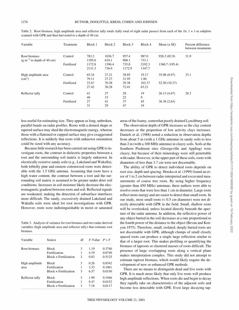
Root biomass, high amplitude area and reflector tally totals foreach of the 16, 1 × 1-m subplots sampled are presented in Ta-ble 2. Both high amplitude area and reflector tally closely fol-lowed the trend observed in root biomass. However, becauseof the high variability in root biomass, the statistical signifi-cance of the fertilizer treatment on root biomass was weak(P = 0.0749; Table 3). Using reflector tally as an index of rootbiomass indicated a statistically significant difference (P =0.0152), whereas using high amplitude area gave a P-valuecloser to that of the actual root biomass (P = 0.1061) and wasnot significant.
Discussion
The successful application of GPR is site-specific. In some ar-eas, conductive soil conditions limited the profiling depth andthe applicability of GPR. The maximum observation depth is,to a large degree, determined by soil conductivity. Soils withhigh electrical conductivity rapidly dissipate electromagneticenergy and restrict observation depth. The principal factors in-fluencing conductivity of soils to electromagnetic radiationare degree of water saturation, amount and type of salts in so-lution, and the amount and type of clay. In addition, detectionof roots is affected by: (1) the electromagnetic gradient exist-ing between a root and the soil; (2) the size, shape, and orienta-tion of a root; (3) the presence of scattering bodies within thesoil; and (4) antenna frequency.
The results of the buried root test are the least ambiguousand provide the best evidence of the value of GPR for sizingroots. The correlation between the area of high amplitude re-flection that meets threshold luminescence and actual root di-ameter is quite good at shallow depths for loblolly pine, butdeclines with increasing soil depth. However, this applies un-der ideal circumstances: only one root was present, the radarscan was perpendicular to the root, and the soil was sandy andamenable to GPR. Under typical field conditions, results canbe confounded when there are many interconnected or adja-cent roots that mask or change the area of the parabola. Orien-tation of the root and the shape of the reflective surface arealso important. Scans made parallel to the buried roots were
TREE PHYSIOLOGY ONLINE at http://heronpublishing.com
STUDY OF TREE ROOTS WITH GROUND-PENETRATING RADAR 1275
Table 1. Comparison of data derived from each radar pass (reflector tally, high amplitude area) to root biomass harvested directly beneath eachpass.
Radar pass Reflector tally High amplitude area
n Correlation coefficient P-Value n Correlation coefficient P-Value
All data correlated to biomass 64 0.36 0.0001 64 0.34 0.0001beneath each radar pass
Four south to north radar passes in each 16 0.45 0.0795 16 0.57 0.0211plot combined and correlated to biomass
Four east to west radar passes in each plot 16 0.46 0.0718 16 0.48 0.0600combined and correlated to biomass
Composite of all eight radar passes 16 0.49 0.0535 16 0.55 0.0274in each plot correlated to biomass
Figure 8. Correlation of total root biomass with (A) high amplitudearea and (B) reflector tally in each plot at the SETRES replicated for-est nutrition study.
Dow
nloaded from https://academ
ic.oup.com/treephys/article/21/17/1269/1669380 by guest on 16 February 2022
less useful for estimating size. They appear as long, unbroken,parallel bands on radar profiles. Roots with a domed shape ortapered surface may shed the electromagnetic energy, whereasthose with a flattened or cupped surface may give exaggeratedreflections. It is unlikely that roots with unknown orientationcould be sized with any accuracy.
Because little research has been carried out using GPR to in-vestigate roots, the contrast in dielectric properties between aroot and the surrounding soil matrix is largely unknown. Inelectrically resistive sandy soils (e.g., Lakeland and Wakulla),both loblolly pine and eastern cottonwood roots were detect-able with the 1.5 GHz antenna. Assuming that roots have ahigh water content, the contrast between a root and the sur-rounding soil matrix is assumed to be greater under drier soilconditions. Increases in soil moisture likely decrease the elec-tromagnetic gradient between roots and soil. Reflected signalsare weakened, making the detection of subsurface interfacesmore difficult. The sandy, excessively drained Lakeland andWakulla soils were ideal for root investigations with GPR.However, roots were indistinguishable in moist or saturated
areas of the loamy, somewhat poorly drained Lynchburg soil.The observation depth of GPR increases as the clay content
decreases or the proportion of low activity clays increases.Daniels et al. (1988) noted a reduction in observation depthsfrom about 5 m (with a 1 GHz antenna) in sandy soils to lessthan 2 m (with a 100 MHz antenna) in clayey soils. Soils at theSouthern Piedmont sites (Georgeville and Appling) wereclayey, but because of their mineralogy were still penetrablewith radar. However, in the upper part of these soils, roots withdiameters of less than 3.7 cm were not discernable.
The ability of GPR to detect individual roots depends onroot size, depth and spacing. Hruska et al. (1999) found an er-ror of 1 to 2 cm between radar-interpreted and excavated mea-surements of coarse tree roots. By using higher frequency(greater than 450 MHz) antennae, these authors were able toresolve roots that were less than 1 cm in diameter. Large rootsreflect more energy and are easier to detect than small roots. Inour study, most small roots (< 0.5 cm diameter) were not di-rectly detectable with GPR in the field. Small, shallow rootswill be overlooked, unless located directly beneath the aper-ture of the radar antenna. In addition, the reflective power ofany object buried in the soil decreases at a rate proportional tothe fourth power of the distance to the object (Bevan and Ken-yon 1975). Therefore, small, isolated, deeply buried roots arenot discernable with GPR, although clumps of small closelyspaced roots can produce a single large reflection similar tothat of a larger root. This makes profiling or quantifying thebiomass of taproots or clustered masses of roots difficult. Thepresence of large overlapping roots along a vertical planemakes interpretation complex. This study did not attempt toestimate taproot biomass, which would likely require the de-velopment of new or enhanced GPR methods.
There are no means to distinguish dead and live roots withGPR. It is much more likely that only live roots will producehigh amplitude reflections. When roots die and begin to decaythey rapidly take on characteristics of the adjacent soils andbecome less detectable with GPR. Even large decaying tap-
1276 BUTNOR, DOOLITTLE, KRESS, COHEN AND JOHNSEN
TREE PHYSIOLOGY VOLUME 21, 2001
Table 2. Root biomass, high amplitude area and reflector tally totals (tally total of eight radar passes) from each of the 16, 1 × 1-m subplotsscanned with GPR and then harvested to a depth of 40 cm.
Variable Treatment Block 1 Block 2 Block 3 Block 4 Mean (± SE) Percent differencebetween treatments
Root biomass Control 783.2 1036.7 957.4 987.0 926.3 (83.9) 31.9(g m–2 to depth of 40 cm) 1395.0 610.1 908.1 733.1
Fertilized 1172.8 1396.4 735.0 2192.3 1360.7 (195.4)2131.3 736.9 1172.9 1347.7
High amplitude area Control 65.24 27.21 38.85 19.17 35.08 (8.97) 33.1(cm2) 79.11 27.27 21.95 1.86
Fertilized 23.67 70.28 29.38 103.37 52.50 (10.27)27.42 30.28 72.41 63.21
Reflector tally Control 41 27 28 19 26.13 (4.67) 28.348 15 22 9
Fertilized 27 41 37 45 36.38 (2.63)31 29 47 34
Table 3. Analysis of variance for root biomass and two radar-derivedvariables (high amplitude area and reflector tally) that estimate rootbiomass.
Variable Source df F-Value P > F
Root biomass Block 3 1.19 0.3740Fertilization 1 4.19 0.0749Block × Fertilization 3 0.83 0.5125
High amplitude Block 3 0.26 0.8542area Fertilization 1 3.32 0.1061
Block × Fertilization 3 6.57 0.0150
Reflector tally Block 3 1.99 0.1946Fertilization 1 9.47 0.0152Block × Fertilization 3 7.18 0.0117
Dow
nloaded from https://academ
ic.oup.com/treephys/article/21/17/1269/1669380 by guest on 16 February 2022

roots, easily seen when excavated, do not provide enough con-trast with the surrounding soil to be detected.
Clutter can be introduced by reflections from objects otherthan roots. Reflections from roots are difficult to distinguishfrom those produced by rock fragments, concretions, animalburrows, cultural debris, or some stratified or segmented soillayers. These scattering bodies produce hyperbolic reflectionsthat can cause destructive interference among several closelyspaced features, making roots difficult or impossible toidentify.
Our attempt to use GPR to quantify treatment differences inroot biomass took place in nearly ideal conditions: SETREShas sandy soils with few rock fragments, and fertilizer treat-ments have resulted in large differences in above- and below-ground biomass (Albaugh et al. 1998). Even so, the correlationbetween both high amplitude areas and reflector tallies withroot biomass was quite remarkable. The overlapping grid-sampling pattern gave the highest correlation to actual rootbiomass. Because the orientation of the roots can influence thesize of the reflection in the radar profile, the sum total of allscans in a grid is most appropriate. Most roots are scannedfrom one direction, and that value is added to another 90° scanto give the best composite data for that plot. The high ampli-tude area analysis technique was the least subjective method.It would be valuable, if feasible, to use GPR to separate bio-mass by size or depth class; however, we were unable to dothis. The major drawback of using high amplitude area is thatreflections travel down the profile, “invading” depth intervalsfrom above, thus masking roots below. If reflection area isused, and advanced signal processing techniques are not, theentire length of each parabolic reflection must be used; it can-not be sectioned by profile depth.
Ground-penetrating radar could be useful for measuring in-creases in root biomass on an annual basis. This would be par-ticularly beneficial in studies where trees are newly estab-lished, initial root biomass is low (available rooting substrateis high), the trees respond to experimental manipulations, androot biomass is noninvasively measured over time. Becauseroots < 0.5 cm in diameter cannot be detected in the field, wedoubt that seasonal fluxes in fine root biomass could be mea-sured.
When assessing the potential use of GPR, a major consider-ation is signal attenuation at the desired antenna operating fre-quency (Daniels et al. 1988). Because signal attenuation in-creases with frequency, low-frequency antennae must be usedin high-loss media to increase observation depth. The maxi-mum observation depth decreases rapidly with increasing an-tenna frequency. High-frequency antennae (> 400 MHz) canprovide well-resolved images of shallow features in soils withlow conductivity. In soils with high conductivity, signal atten-uation becomes prohibitive (Daniels et al. 1988). In thesesoils, low-frequency antennae increase observation depth.However, as lower frequencies are used to achieve greater ob-servation depth, resolution is diminished and smaller featuresare more likely to be overlooked. High resolution is vital forthe detection of small roots.
Although Wakulla and Lakeland soils have similar proper-ties, the cottonwood root in an area of Lakeland soil could notbe accurately sized. Because the Wakulla and Lakeland soilshad similar dielectric properties (dielectric permittivity of 7.8and 7.9, respectively), the difference in resolution is likelyrelated to species-specific root properties. Loblolly pine hasbeen shown to have 21% higher specific gravity (G) than cot-tonwood (Panshin and de Zeeuw 1980). The higher G likelyprovides better dielectric contrast between the root and the soilmatrix. Specific gravity may therefore be useful for predictingwhether tree roots can be detected and accurately sized withGPR. In this study, loblolly pine roots were detectable, and itis likely that trees with roots of equal or greater G would alsogive satisfactory reflections. Hruska et al. (1999) reportedgreater success with root imaging by GPR than that achievedin this study; this may be related to their use of an oak specieswhich likely has a higher G than that of loblolly pine or easterncottonwood.
Conclusions
Soil with high electrical resistivity was the most amenable toroot detection with GPR. The 1.5 GHz antenna gave the bestresolution and was able to detect roots as small as 0.5 cm in di-ameter. The high clay contents and more electrically conduc-tive properties of Appling and Georgeville soils limitedpenetration depth. Pine roots could be sized accurately (0.5 to6.5 cm in diameter), but only when the orientation of the rootswas known. The ability to delineate root size declined withprofile depth. The cottonwood root could not be sized usingGPR, possibly because of the low G of roots of this species.
Ground-penetrating radar was useful in assessing total rootbiomass at SETRES, but did not allow delineation of biomassby root size class. With suitable soil conditions (well drainedto excessively drained, sandy soils with low conductivity, andabsence of scattering bodies), GPR can be a valuable tool fornoninvasive root biomass estimation and may prove useful forthe nondestructive measurement of root biomass growth overtime. It is probable that tighter grid spacing (i.e., 5 cm) of radarpasses may yield even better correlations with root biomass.
Ground-penetrating radar did not appear useful for mappingroots over diverse terrain. Radar antennae need to maintaincontact with the ground while being pulled at a fairly constantspeed. This was difficult where undergrowth, logs, raised bedsand logging slash impeded smooth advance of the antenna.
Tight clusters of roots often gave one large parabolic reflec-tion, which prevented individual roots being distinguished.This is the greatest impediment to mapping complete root sys-tems with radar. The use of more advanced data processingtechniques, such as horizontal and vertical band-pass filteringand migration, may help improve the discrimination of someclosely spaced roots and facilitate in situ imaging of tree rootstructure. Ground-penetrating radar can provide valuable datain small intensively studied plots, provided that the proper an-tenna is used. With current technology, and under appropriateconditions, GPR can be particularly useful for augmenting tra-ditional and time-consuming root harvesting.
TREE PHYSIOLOGY ONLINE at http://heronpublishing.com
STUDY OF TREE ROOTS WITH GROUND-PENETRATING RADAR 1277
Dow
nloaded from https://academ
ic.oup.com/treephys/article/21/17/1269/1669380 by guest on 16 February 2022

Acknowledgments
We thank Dan Delea and Geophysical Survey Systems, Inc., for tech-nical assistance and the use of the 1.5 GHz antenna, and Dr. PhilipDougherty (Westvaco Corp.) and Dr. Daniel Richter (Duke Univer-sity) for help locating study sites. We also appreciate the efforts ofDrs. Joseph Hendricks, Ronald Hendrick and Marianne Burke whoreviewed this manuscript prior to submission.
References
Albaugh, T.J., H.L. Allen, P.M. Dougherty, L.W. Kress and J.S.King. 1998. Leaf area and above- and belowground growth re-sponses of loblolly pine to nutrient and water additions. For. Sci.44:1–12.
Annan, A.P. and S.W. Cosway. 1994. GPR frequency selection. InProc. Fifth Int. Conference on Ground Penetrating Radar. Water-loo Centre for Groundwater Research and Canadian GeotechnicalSociety, Kitchener, ON, pp 747–760.
Austin, M.E. 1965. Land resource regions and major land resourceareas of the United States. USDA Soil Conservation Service. Agri-cultural Handbook 296. Washington, DC, 82 p.
Barker, D.B. and J. Doolittle. 1992. Ground-penetrating radar—an ar-chaeological tool. Cult. Resour. Manage. 15:25–28.
Bevan, B.W. 1984. Environmental effects on ground-penetrating ra-dar. In Expanded Abstracts, 54th Annual International SEG Meet-ing. Soc. Explore. Geophys., Atlanta, GA, pp 201–204.
Bevan, B. and J. Kenyon. 1975. Ground-probing radar for historicalarchaeology. MASCA (Museum Applied Science Center for Ar-chaeology), Univ. Pennsylvania, Newsletter 11:2–7.
Bruschini, C., B. Gross, F. Guernsey, P.Y. Piece and O. Carmon.1998. Ground penetrating radar and image metal detector forantipersonnel mines. J. Appl. Geophys. 40:59–71.
Chow, T.L. and H.W. Rees. 1989. Identification of subsurface drainlocations with ground-penetrating radar. Can. J. Soil Sci. 69:223–234.
Conyers, L.B. and D. Goodman. 1997. Ground-penetrating radar: anintroduction for archaeologists. Alta Mira Press, Walnut Creek,CA, 232 p.
Daniels, D.J. 1996. Surface-penetrating radar. Inst. Electrical Engi-neers, London, 300 p.
Daniels, D.J. 1998. Ground probing radar techniques for mine detec-tion. In Proc. Seventh Int. Conference on Ground-Penetrating Ra-dar. Ed. R.G. Plumb. Radar Systems and Remote Sensing Lab.,Univ. Kansas, pp 313–317.
Daniels, D.J., D.J. Gunton and H.F. Scott. 1988. Introduction to sub-surface radar. In IEE Proceedings on Communication, Radar, andSignal Processing. Vol. 135. Part F. pp 278–320.
Doolittle, J.A. and W.F. Miller. 1991. Use of ground-penetrating ra-dar in archaeological investigations. In Application of Space-AgeTechnology in Anthropology Conference Proceedings. Eds. C.A.Behrens and T.L. Sever. NASA John C. Stennis Space Center Spe-cial Publication, pp 81–94.
Farrish, K.W., J.A. Doolittle and E.E. Gamble. 1990. Loamy sub-strata and forest productivity of sandy glacial drift soils in Michi-gan. Can. J. Soil Sci. 70:181–187.
Hruska, J., J. Èermák and S. Sustek. 1999. Mapping tree root systemswith ground-penetrating radar. Tree Physiol. 19:125–130.
Morey, R.M. 1974. Continuous subsurface profiling by impulse ra-dar. In Proc. ASCE Engineering Foundation Conference on Sub-surface Exploration for Underground Excavations and HeavyConstruction. Am. Soc. Engineers, New York, pp 212–232.
Panshin, A.J. and C. de Zeeuw. 1980. Textbook of wood technology:structure, identification, properties and uses of the commercialwoods of the United States and Canada. McGraw-Hill, New York,722 p.
Roberts, R.L. and J.J. Daniels. 1993. Analysis of the effectiveness ofvelocity-depth inversion using bistatic GPR data collected over tar-gets of different sizes, shapes, and orientations. In Proc. SecondGovernment Workshop on GPR, Advanced Ground PenetratingRadar: Technologies and Applications. Eds. M. Vendl and J.J.Daniels. Ohio State Univ., Columbus, OH, pp 83–99.
Soil Survey Staff. 1999. Soil taxonomy: a basic system of soil classi-fication for making and interpreting soil surveys. 2nd Edn. USDANatural Resources Conservation Service. Agricultural Handbook436. U.S. Government Printing Office, Washington, DC, 869 p.
Truman, C.C., H.F. Perkins, L.E. Asmussen and H.D. Allison. 1988.Some applications of ground-penetrating radar in southern CoastalPlains Region of Georgia. The Georgia Agric. Exp. Stations, Col-lege of Agriculture, Univ. Georgia, Athens, GA. Research Bulletin362, 27 p.
Ulriksen, C.P.F. 1982. Application of impulse radar to civil engineer-ing. Ph.D. Thesis. Dept. Engineering Geology, Lund Univ. Tech-nology, Lund, Sweden, 179 p.
1278 BUTNOR, DOOLITTLE, KRESS, COHEN AND JOHNSEN
TREE PHYSIOLOGY VOLUME 21, 2001
Dow
nloaded from https://academ
ic.oup.com/treephys/article/21/17/1269/1669380 by guest on 16 February 2022