Embed Size (px)
Citation preview
Use of Electrochemical Chloride Extraction and Associated Repairs to Extend the Beneficial Life of Reinforced Concrete Substructures http://www.virginiadot.org/vtrc/main/online_reports/pdf/16-r16.pdf STEPHEN R. SHARP, Ph.D., P.E. Senior Research Scientist
Final Report VTRC 16-R16
Standard Title Page - Report on Federally Funded Project
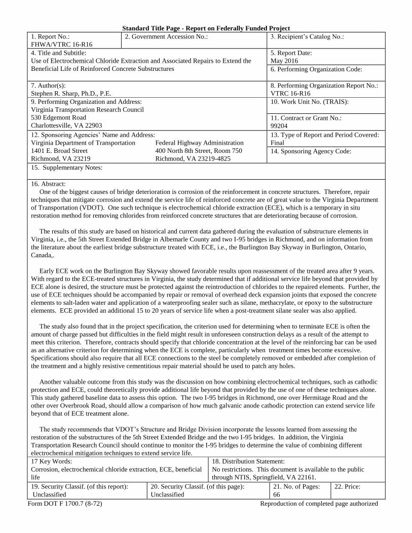
1. Report No.: 2. Government Accession No.: 3. Recipient’s Catalog No.:
FHWA/VTRC 16-R16
4. Title and Subtitle: 5. Report Date:
Use of Electrochemical Chloride Extraction and Associated Repairs to Extend the
Beneficial Life of Reinforced Concrete Substructures
May 2016
6. Performing Organization Code:
7. Author(s):
Stephen R. Sharp, Ph.D., P.E.
8. Performing Organization Report No.:
VTRC 16-R16
9. Performing Organization and Address:
Virginia Transportation Research Council
530 Edgemont Road
Charlottesville, VA 22903
10. Work Unit No. (TRAIS):
11. Contract or Grant No.:
99204
12. Sponsoring Agencies’ Name and Address: 13. Type of Report and Period Covered:
Virginia Department of Transportation
1401 E. Broad Street
Richmond, VA 23219
Federal Highway Administration
400 North 8th Street, Room 750
Richmond, VA 23219-4825
Final
14. Sponsoring Agency Code:
15. Supplementary Notes:
16. Abstract:
One of the biggest causes of bridge deterioration is corrosion of the reinforcement in concrete structures. Therefore, repair
techniques that mitigate corrosion and extend the service life of reinforced concrete are of great value to the Virginia Department
of Transportation (VDOT). One such technique is electrochemical chloride extraction (ECE), which is a temporary in situ
restoration method for removing chlorides from reinforced concrete structures that are deteriorating because of corrosion.
The results of this study are based on historical and current data gathered during the evaluation of substructure elements in
Virginia, i.e., the 5th Street Extended Bridge in Albemarle County and two I-95 bridges in Richmond, and on information from
the literature about the earliest bridge substructure treated with ECE, i.e., the Burlington Bay Skyway in Burlington, Ontario,
Canada,.
Early ECE work on the Burlington Bay Skyway showed favorable results upon reassessment of the treated area after 9 years.
With regard to the ECE-treated structures in Virginia, the study determined that if additional service life beyond that provided by
ECE alone is desired, the structure must be protected against the reintroduction of chlorides to the repaired elements. Further, the
use of ECE techniques should be accompanied by repair or removal of overhead deck expansion joints that exposed the concrete
elements to salt-laden water and application of a waterproofing sealer such as silane, methacrylate, or epoxy to the substructure
elements. ECE provided an additional 15 to 20 years of service life when a post-treatment silane sealer was also applied.
The study also found that in the project specification, the criterion used for determining when to terminate ECE is often the
amount of charge passed but difficulties in the field might result in unforeseen construction delays as a result of the attempt to
meet this criterion. Therefore, contracts should specify that chloride concentration at the level of the reinforcing bar can be used
as an alternative criterion for determining when the ECE is complete, particularly when treatment times become excessive.
Specifications should also require that all ECE connections to the steel be completely removed or embedded after completion of
the treatment and a highly resistive cementitious repair material should be used to patch any holes.
Another valuable outcome from this study was the discussion on how combining electrochemical techniques, such as cathodic
protection and ECE, could theoretically provide additional life beyond that provided by the use of one of these techniques alone.
This study gathered baseline data to assess this option. The two I-95 bridges in Richmond, one over Hermitage Road and the
other over Overbrook Road, should allow a comparison of how much galvanic anode cathodic protection can extend service life
beyond that of ECE treatment alone.
The study recommends that VDOT’s Structure and Bridge Division incorporate the lessons learned from assessing the
restoration of the substructures of the 5th Street Extended Bridge and the two I-95 bridges. In addition, the Virginia
Transportation Research Council should continue to monitor the I-95 bridges to determine the value of combining different
electrochemical mitigation techniques to extend service life.
17 Key Words: 18. Distribution Statement:
Corrosion, electrochemical chloride extraction, ECE, beneficial
life
No restrictions. This document is available to the public
through NTIS, Springfield, VA 22161.
19. Security Classif. (of this report): 20. Security Classif. (of this page): 21. No. of Pages: 22. Price:
Unclassified Unclassified 66
Form DOT F 1700.7 (8-72) Reproduction of completed page authorized

FINAL REPORT
USE OF ELECTROCHEMICAL CHLORIDE EXTRACTION AND ASSOCIATED
REPAIRS TO EXTEND THE BENEFICIAL LIFE OF REINFORCED CONCRETE
SUBSTRUCTURES
Stephen R. Sharp, Ph.D., P.E.
Senior Research Scientist
In Cooperation with the U.S. Department of Transportation
Federal Highway Administration
Virginia Transportation Research Council
(A partnership of the Virginia Department of Transportation
and the University of Virginia since 1948)
Charlottesville, Virginia
May 2016
VTRC 16-R16

ii
DISCLAIMER
The contents of this report reflect the views of the author, who is responsible for the facts
and the accuracy of the data presented herein. The contents do not necessarily reflect the official
views or policies of the Virginia Department of Transportation, the Commonwealth
Transportation Board, or the CP. This report does not constitute a standard, specification, or
regulation. Any inclusion of manufacturer names, trade names, or trademarks is for
identification purposes only and is not to be considered an endorsement.
Copyright 2016 by the Commonwealth of Virginia.
All rights reserved.
iii
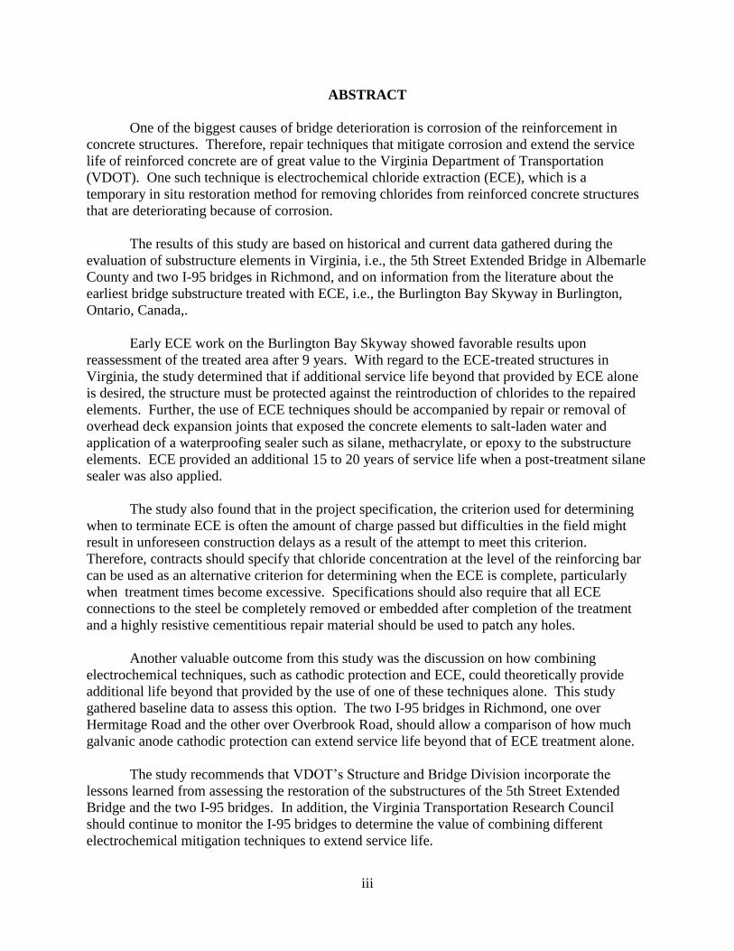
ABSTRACT
One of the biggest causes of bridge deterioration is corrosion of the reinforcement in
concrete structures. Therefore, repair techniques that mitigate corrosion and extend the service
life of reinforced concrete are of great value to the Virginia Department of Transportation
(VDOT). One such technique is electrochemical chloride extraction (ECE), which is a
temporary in situ restoration method for removing chlorides from reinforced concrete structures
that are deteriorating because of corrosion.
The results of this study are based on historical and current data gathered during the
evaluation of substructure elements in Virginia, i.e., the 5th Street Extended Bridge in Albemarle
County and two I-95 bridges in Richmond, and on information from the literature about the
earliest bridge substructure treated with ECE, i.e., the Burlington Bay Skyway in Burlington,
Ontario, Canada,.
Early ECE work on the Burlington Bay Skyway showed favorable results upon
reassessment of the treated area after 9 years. With regard to the ECE-treated structures in
Virginia, the study determined that if additional service life beyond that provided by ECE alone
is desired, the structure must be protected against the reintroduction of chlorides to the repaired
elements. Further, the use of ECE techniques should be accompanied by repair or removal of
overhead deck expansion joints that exposed the concrete elements to salt-laden water and
application of a waterproofing sealer such as silane, methacrylate, or epoxy to the substructure
elements. ECE provided an additional 15 to 20 years of service life when a post-treatment silane
sealer was also applied.
The study also found that in the project specification, the criterion used for determining
when to terminate ECE is often the amount of charge passed but difficulties in the field might
result in unforeseen construction delays as a result of the attempt to meet this criterion.
Therefore, contracts should specify that chloride concentration at the level of the reinforcing bar
can be used as an alternative criterion for determining when the ECE is complete, particularly
when treatment times become excessive. Specifications should also require that all ECE
connections to the steel be completely removed or embedded after completion of the treatment
and a highly resistive cementitious repair material should be used to patch any holes.
Another valuable outcome from this study was the discussion on how combining
electrochemical techniques, such as cathodic protection and ECE, could theoretically provide
additional life beyond that provided by the use of one of these techniques alone. This study
gathered baseline data to assess this option. The two I-95 bridges in Richmond, one over
Hermitage Road and the other over Overbrook Road, should allow a comparison of how much
galvanic anode cathodic protection can extend service life beyond that of ECE treatment alone.
The study recommends that VDOT’s Structure and Bridge Division incorporate the
lessons learned from assessing the restoration of the substructures of the 5th Street Extended
Bridge and the two I-95 bridges. In addition, the Virginia Transportation Research Council
should continue to monitor the I-95 bridges to determine the value of combining different
electrochemical mitigation techniques to extend service life.

1
FINAL REPORT
USE OF ELECTROCHEMICAL CHLORIDE EXTRACTION AND ASSOCIATED
REPAIRS TO EXTEND THE BENEFICIAL LIFE OF REINFORCED CONCRETE
SUBSTRUCTURES
Stephen R. Sharp, Ph.D., P.E.
Senior Research Scientist
INTRODUCTION
According to Koch et al. (2002), the annual direct cost associated with corrosion of
bridges according to the Federal Highway Administration (FHWA) was estimated to be up to
$8.3 billion in 2002. Therefore, repair techniques that mitigate corrosion and extend the service
life of a reinforced concrete bridge are of great value to all state departments of transportation.
One mitigation technique, electrochemical chloride extraction (ECE), is a temporary in situ
restoration technique for reinforced concrete structures that are deteriorating because of
corrosion. Although ECE is generally the focus of the repair, the value of performing other
maintenance of the structure as part of the repair contract, such as joint repairs or concrete
sealing, can increase the beneficial life after ECE. In addition, some have proposed installing
cathodic protection (CP) on a structure after ECE to increase the beneficial life further.
However, to maximize the benefit of ECE treatment on service life extension, it is important to
understand how ECE works.
ECE is used to remove chloride ions from reinforced concrete while increasing the
alkalinity near the reinforcing steel (Bennett and Thomas, 1993; Chatterji, 1994; Google, 2000).
ECE systems apply current densities of up to 1A/m2 for usually 4 to 8 weeks, which reduce
chloride levels while increasing the alkalinity at the reinforcement, both of which enhance the
corrosion resistance of the steel (Bennett and Thomas, 1993; Clemeña and Jackson, 1997;
Elsener and Böhni, 1994). A schematic showing corrosion being initiated followed by ECE
treatment is shown in Figure 1.
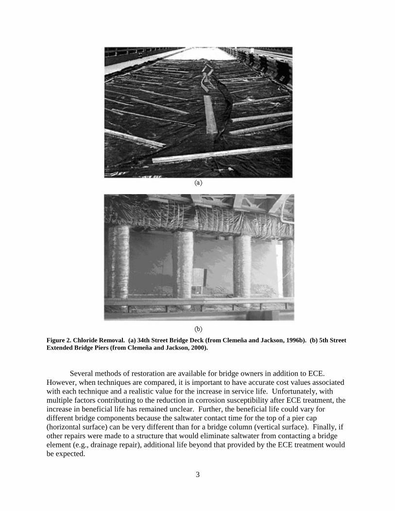
Concrete bridge decks require traffic control during ECE treatment; however, chloride
extraction of bridge piers does not generally require the extensive re-routing of traffic because
the treatment can be performed without encroaching on the roadway. Examples of equipment on
a bridge deck and pier are shown in Figure 2. In Figure 2a, the 34th Street Bridge that crosses
I-395 in Arlington, Virginia, is having chlorides electrochemically removed from the bridge
deck. In Figure 2b, the piers of the 5th Street Extended Bridge over I-64 in Albemarle County,
Virginia (hereinafter 5th Street Extended Bridge), are being treated. From these photographs it is
evident that the travel lane cannot be used during ECE treatment on a bridge deck. However,
when the substructure is treated, the increase in circumference for each column and the pier cap
after installation of the treatment system is relatively insignificant and the roadway is not
encroached. Therefore, it is important to consider how treating a particular reinforced concrete
element with ECE will influence the local traffic flow.
2
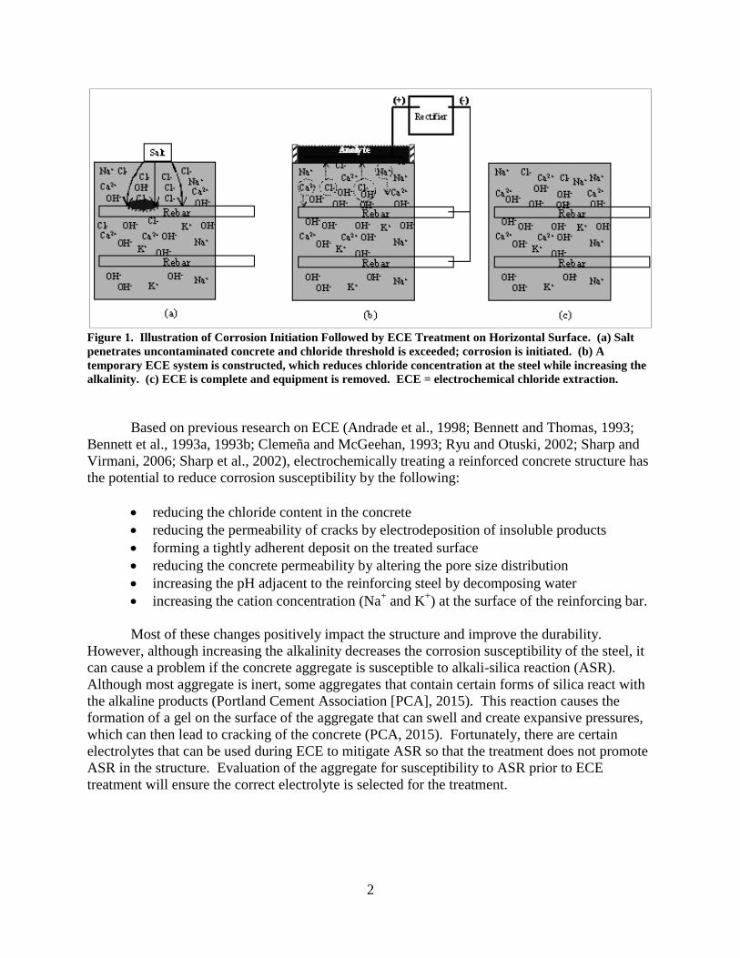
Figure 1. Illustration of Corrosion Initiation Followed by ECE Treatment on Horizontal Surface. (a) Salt
penetrates uncontaminated concrete and chloride threshold is exceeded; corrosion is initiated. (b) A
temporary ECE system is constructed, which reduces chloride concentration at the steel while increasing the
alkalinity. (c) ECE is complete and equipment is removed. ECE = electrochemical chloride extraction.
Based on previous research on ECE (Andrade et al., 1998; Bennett and Thomas, 1993;
Bennett et al., 1993a, 1993b; Clemeña and McGeehan, 1993; Ryu and Otuski, 2002; Sharp and
Virmani, 2006; Sharp et al., 2002), electrochemically treating a reinforced concrete structure has
the potential to reduce corrosion susceptibility by the following:
reducing the chloride content in the concrete
reducing the permeability of cracks by electrodeposition of insoluble products
forming a tightly adherent deposit on the treated surface
reducing the concrete permeability by altering the pore size distribution
increasing the pH adjacent to the reinforcing steel by decomposing water
increasing the cation concentration (Na+ and K
+) at the surface of the reinforcing bar.
Most of these changes positively impact the structure and improve the durability.
However, although increasing the alkalinity decreases the corrosion susceptibility of the steel, it
can cause a problem if the concrete aggregate is susceptible to alkali-silica reaction (ASR).
Although most aggregate is inert, some aggregates that contain certain forms of silica react with
the alkaline products (Portland Cement Association [PCA], 2015). This reaction causes the
formation of a gel on the surface of the aggregate that can swell and create expansive pressures,
which can then lead to cracking of the concrete (PCA, 2015). Fortunately, there are certain
electrolytes that can be used during ECE to mitigate ASR so that the treatment does not promote
ASR in the structure. Evaluation of the aggregate for susceptibility to ASR prior to ECE
treatment will ensure the correct electrolyte is selected for the treatment.
3
Figure 2. Chloride Removal. (a) 34th Street Bridge Deck (from Clemeña and Jackson, 1996b). (b) 5th Street
Extended Bridge Piers (from Clemeña and Jackson, 2000).
Several methods of restoration are available for bridge owners in addition to ECE.
However, when techniques are compared, it is important to have accurate cost values associated
with each technique and a realistic value for the increase in service life. Unfortunately, with
multiple factors contributing to the reduction in corrosion susceptibility after ECE treatment, the
increase in beneficial life has remained unclear. Further, the beneficial life could vary for
different bridge components because the saltwater contact time for the top of a pier cap
(horizontal surface) can be very different than for a bridge column (vertical surface). Finally, if
other repairs were made to a structure that would eliminate saltwater from contacting a bridge
element (e.g., drainage repair), additional life beyond that provided by the ECE treatment would
be expected.

4
PURPOSE AND SCOPE
The purpose of this study was to determine the beneficial life after the treatment of
substructure elements using ECE and associated repair techniques by evaluating structures
treated with ECE, thus leading to an increased understanding of the influence ECE and
associated repair techniques can have on extending the service life of a corroding bridge
substructure element.
Specifically, the results of the study are based on historical and current data gathered by
the Virginia Department of Transportation (VDOT) during the evaluation of actual substructure
elements in Virginia, i.e., the 5th Street Extended Bridge and two I-95 bridges in Richmond, in
addition to findings from the literature about the Burlington Bay Skyway in Burlington, Ontario,
Canada, which was the earliest bridge substructure treated with ECE in North America.
The study also captured critical baseline information that will be useful in understanding
how combining electrochemical mitigation techniques could further extend service life beyond
that provided solely by ECE. This will provide bridge engineers with the knowledge they need
to make decisions regarding the incorporation of ECE as a restoration technique.
METHODS
Literature Review
Although this study focused on ECE, several supplementary techniques can potentially
increase service life after its application. Bridge deck joint repair and concrete sealing would
both reduce the ability of the chloride-containing saltwater solutions to penetrate the concrete
and extend service life after ECE. The 5th Street Extended Bridge is an example of bridge piers
being sealed after ECE, so this project was included as part of the literature review. More
recently, it has been suggested that using galvanic anode CP (GACP) after ECE treatment of
reinforced concrete can reduce the corrosion rate and further extend service life. The I-95 11-
bridge restoration project in Richmond is an example of this mitigation approach. A review of
the literature was performed before the onset of that restoration project to determine if other
bridge elements had received both ECE and CP.
In addition, a review of the literature was performed to identify any physical evaluations
of any of the reinforced concrete substructure elements originally treated with ECE. Of
particular interest was the pier of the Burlington Bay Skyway in Burlington, Ontario, Canada.
This structure was of interest because it was the first substructure element treated with ECE in
North America, having undergone ECE in 1989 (Pianca et al., 2003; Sharp et al., 2002).

5
Field Structures Selected for Study
5th Street Extended Bridge
Overview
Built in 1969, the 5th Street Extended Bridge (VA. Str. No. 6302), shown in Figure 3,
carries Route 631 (5th Street Extended) over the eastbound and westbound lanes of I-64 in
Albemarle County, Virginia. The structure is a four-span multi–steel girder bridge that has a
total length of 334 ft. The joints in this bridge can also be seen in Figure 3, half of which are
located above each pier. The substructure consists of reinforced concrete piers and caps, which
provided the main area of interest for this study as evaluating their current condition provides an
evaluation of the effectiveness of ECE and subsequent silane sealing treatment after almost 20
years of service. The comparison is aided by the fact that selected piers and caps were treated
with ECE and other piers and caps were selected to be controls (i.e., remain untreated).
It is also important to highlight that this bridge is exposed to salt from snow and ice
removal operations that occur along both 5th Street Extended, which crosses over the bridge, and
I-64, which crosses under the bridge. In 2014, the average daily traffic along 5th Street
Extended was in excess of 15,000 vehicles and traffic along I-64 exceeded 20,000 vehicles.
During snow and ice events, this comprises a sizable number of vehicles that subject the deck
and substructure to deicing salt, so clearly this bridge is a representative candidate structure for
testing and assessing the benefit of this technology.
The ECE system was energized in late April 1995, and treatment was terminated in early
July of the same year. Clemeña and Jackson (1996a) stated that a silane sealer was applied to the
piers after the ECE treatment was completed. The method used to treat the bridge and selected
electrical measurements from this treatment were provided by Clemeña and Jackson (2000).
Current Evaluation
Review of Inspection Reports. The VDOT inspection reports for the 5th Street
Extended Bridge were reviewed to assess the change in condition over time. The bridge is
subject to a 24-month inspection cycle. The reports evaluated were for inspections made in
2006, 2008, 2010, 2012, and 2013.
Visual Observations. A visual survey of the substructure was performed to assess the
current condition after ECE treatment. To document any areas of interest, notes were made and
photographs were taken.
Chloride Samples. An analysis of the concrete samples for chlorides was performed in
accordance with ASTM C1152, with the assumption that the unit weight of concrete is 3,915
lb/yd3
(ASTM International [ASTM], 2012). Chloride samples were gathered for this study from
Columns 1 (C1) and 7 (C7) in Piers 1 (P1) and 3 (P3). The plan view is shown in Figure 3, and a
sketch of the general locations of the samples is shown in Figure 4. Concrete samples for
analysis were gathered by horizontal drilling into the column at the following increments when
permissible:

6
Figure 3. Plan View of 5th Street Extended Bridge
7
between the surface and ¼-in depth
between ¼-in depth and ¾-in depth
between ¾-in depth and 1¼-in depth
between 1¼-in depth and 1¾-in depth
between 1¾-in depth and 2¼-in depth
between 2¼ -in depth and 2¾-in depth
between 2¾-in depth and 3¼-in depth
between 3¼ -in depth and 3¾-in depth
between 3¾-in depth and 4¼-in depth
between 4¼-in depth and 4¾-in depth.
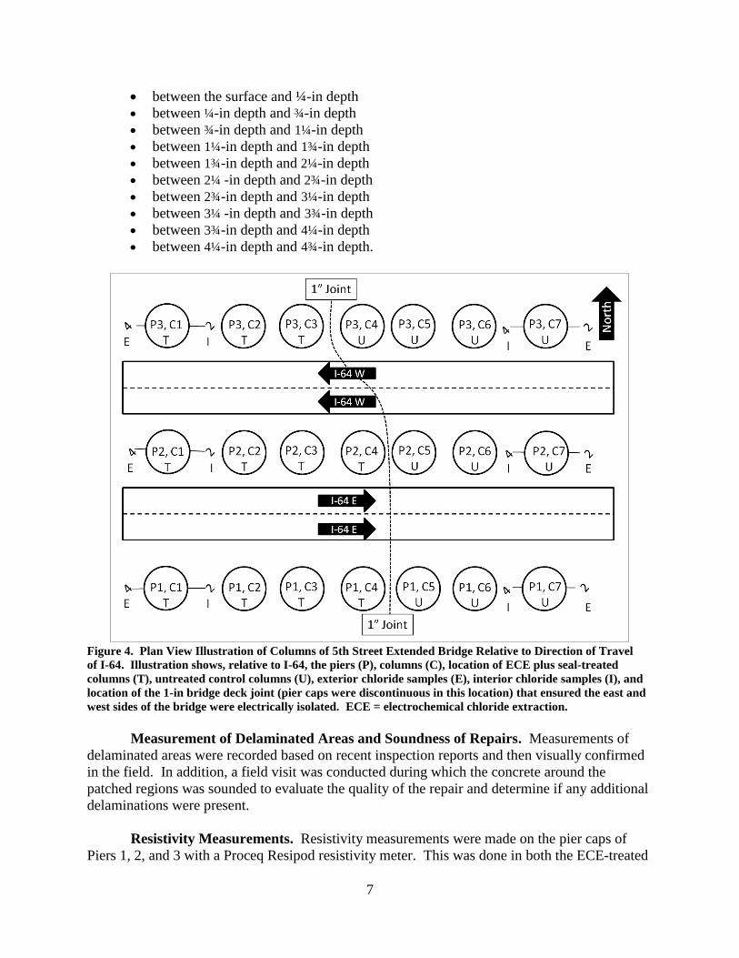
Figure 4. Plan View Illustration of Columns of 5th Street Extended Bridge Relative to Direction of Travel
of I-64. Illustration shows, relative to I-64, the piers (P), columns (C), location of ECE plus seal-treated
columns (T), untreated control columns (U), exterior chloride samples (E), interior chloride samples (I), and
location of the 1-in bridge deck joint (pier caps were discontinuous in this location) that ensured the east and
west sides of the bridge were electrically isolated. ECE = electrochemical chloride extraction.
Measurement of Delaminated Areas and Soundness of Repairs. Measurements of
delaminated areas were recorded based on recent inspection reports and then visually confirmed
in the field. In addition, a field visit was conducted during which the concrete around the
patched regions was sounded to evaluate the quality of the repair and determine if any additional
delaminations were present.
Resistivity Measurements. Resistivity measurements were made on the pier caps of
Piers 1, 2, and 3 with a Proceq Resipod resistivity meter. This was done in both the ECE-treated
8
and untreated concrete regions and in both patched and unpatched areas. To perform this work, a
four-pin resistivity meter was used with an equal spacing of 1½ in (38 mm) between each pair of
pins.
Half-cell Potential Measurements. Half-cell potential measurements were made on
Piers 1 and 2, Columns 1 and 7, and the pier cap area above each of these columns; these
locations are illustrated in Figures 3 and 4. A copper/copper sulfate electrode (CSE) was used as
a reference electrode. Measurements were made in accordance with ASTM C876 (ASTM,
2009).
Concrete Depth of Cover Measurements. An Elcometer 331 concrete cover meter was
used to measure cover depths directly over the embedded steel reinforcement. Concrete depth of
cover measurements were made on Piers 1, 2, and 3 on Columns 1 and 7; these locations are
illustrated in Figures 3 and 4.
I-95 Bridges
Overview
In 2010, VDOT initiated a 4-year project to revitalize and extend the service life of 11
bridges that support the traffic flow along I-95 through Richmond, Virginia. Some of these
bridges carry I-95 traffic along the I-95 corridor, whereas others provide ramps on and off the
freeway. One of the primary durability concerns was that a superstructure designed for a 75-year
service life was going to be placed on a substructure built in the late 1950s or early 1960s. It was
known that this would result in the placement of new, chloride-free concrete in direct contact
with older chloride-contaminated concrete, with the older contaminated concrete supporting the
new uncontaminated concrete. Since this raised concerns about corrosion, the use of mitigation
techniques for extending the life of the substructure was essential. VDOT worked with several
consultants to develop a restoration plan, which ultimately included ECE to treat the I-95 bridges
that cross over Hermitage Road (Str. No. 2842) and over Overbrook Road (Str. No. 2839) as one
of the critical components.
Current Evaluation
Although it is too soon to determine the benefit of using ECE for these bridges, it is
important to archive the restoration methods and current conditions for each bridge so that future
investigators can evaluate the efficacy of the recent interventions. This set of bridges is
especially important for evaluating long-term behavior as they are in relatively close proximity
to each other and the repairs were performed under the same contractor. Further, the following
restoration techniques were employed:
elimination of leaking joints (at certain piers only)
ECE treatment on selected substructures
installation of CP on selected substructures
sealing of concrete after ECE treatment.
9
Each of these restoration techniques when properly used can extend substructure service
life. However, it is not clear exactly how much longer the service life extension will be when
several of these restoration techniques are combined. Establishment of a baseline and then
periodic monitoring will help in determining how various restoration techniques contribute to
service life extension after the repair.
RESULTS AND DISCUSSION
Literature Review
Joint Repair
As discussed in the “Introduction” section, exposure of the steel reinforcement to salt
tends to accelerate rapidly the corrosion of the steel reinforcement in the concrete elements. In
Virginia, for inland structures, salt is almost always introduced from either leaking expansion
joints from the deck above or salt spray from adjacent traffic, with compromised expansion
joints allowing for the vast majority of this salt exposure. Accordingly, the integrity of deck
joints and the ability of the deck to protect substructure elements from salt and moisture are
critical for bridge durability.
Section 212 of VDOT’s 2007 Road and Bridge Specifications (VDOT, 2007) provides
guidance on joint materials, which are described as “resilient products made from various
materials that are designed to accommodate the movement of rigid structures, such as component
parts of hydraulic cement concrete, and seal the joint from intrusion of water or
incompressibles.” The requirements with regard to the various joint sealers are detailed in
Section 212, with this section also indicating that approval by VDOT’s Materials Division for
silicone rubber joint sealer is necessary. VDOT’s Materials Division maintains a list available to
the public that indicates the products that are approved for use on VDOT structures. The
approved silicone rubber joint and asphaltic plug joint repair materials are on this list (VDOT,
2015b).
Although sealing joints can restrict the flow of moisture and protect the underlying
element, different seals can have different life expectancies. In recognition of the significance of
compromised expansion joints in accelerating the corrosion of bridge elements, the forthcoming
2016 edition of VDOT’s Road and Bridge Specifications and Part 2 of VDOT’s Manual of the
Structure and Bridge Division (VDOT, 2015c) provide stricter restrictions on the use of
expansion joints. Specifically, expansion joints are allowed on new bridges only if a written
design exception is provided; further, for bridges receiving rehabilitation, either the existing
joints must be eliminated or more durable joint seal materials such as elastomeric expansion
dams (strip seals) or seals that rely on durable adhesives must be used. Poured silicone seals will
be permitted only on low volume roads, and preformed elastomeric joint sealers (compression
seals) will no longer be permitted on any VDOT bridge.
10
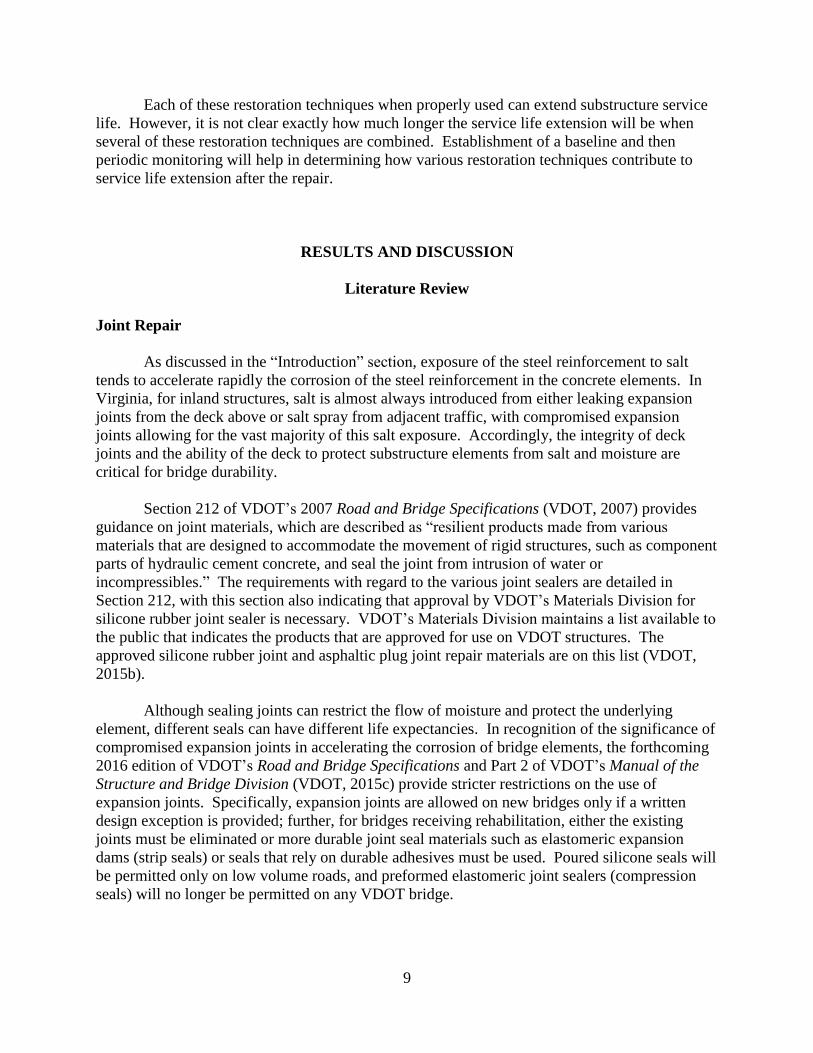
The functional life performance can be dependent on whether the seal was installed
during initial construction or during rehabilitation. Milner and Shenton (2015) discussed
experiences and the state of the practice with regard to expansion joints that are used in the
Northeast. The data collected in this work, shown in Figure 5, demonstrated that there is
variability with different joint seals. This is important since in some cases after ECE treatment
of a substructure element, an extension in service life could result as long as the seal restricts
moisture, including saltwater, from reaching the treated element. Based on the work of Milner
and Sherton (2015), 2 to 10 years can be expected on average before joint failure for
maintenance or repair installations. Unfortunately, in some instances in Virginia, particularly on
interstate highways, compromised joint seals have been observed within 12 months of
installation. Therefore, ideally, if both joint repairs and ECE were performed on a substructure
element protected from salt exposure by the deck, the additional time before failure of the joint
would prolong the beneficial life as a result of both repairing the joints and performing ECE
repair.
Figure 5. Comparative Results From the Northeast Bridge Preservation Partnership Study on the Functional
Life of Bridge Joints. Based on data from Milner and Shenton (2015).
Concrete Sealant
Concrete sealants are used to provide a barrier that restricts the contamination of concrete
by chlorides. VDOT’s Materials Division maintains a list available to the public that indicates
the products that are approved for use on VDOT structures (VDOT, 2015b). The approved
concrete sealants are listed under “Hydraulic Cement and Concrete Sealants, Stains, and
Coatings” in this list.
Although NACE International’s (NACE) Standard Practice SP0107-2007,
Electrochemical Realkalization and Chloride Extraction for Reinforced Concrete, discusses

11
applying ECE to reinforced concrete (NACE, 2007a), it does not mention sealing the concrete
after applying ECE. NACE’s Electrochemical Chloride Extraction from Steel Reinforced
Concrete—A State of the Art Report, however, does discuss different post-treatment options,
which include sealers (NACE, 2001). This is important to highlight since on the Virginia
bridges discussed in this report, the 5th Street Extended Bridge and the solely ECE–treated I-95
bridge, a sealant was used after ECE treatment.
Cathodic Protection
CP systems are designed to reduce the corrosion rate in a structure. Currently, VDOT
does not usually design, install, or perform maintenance on CP systems that are incorporated into
its structures but instead uses private consultants and contractors to perform this work.
Although CP systems are usually specifically designed for a given structure, NACE has
provided guidance that can be used by transportation agencies and consultants as they design CP
systems. These NACE reports and standard practices that support CP design, installation, and
maintenance for reinforced concrete structures include the following:
Standard Practice SP0187-2008: Design Considerations for Corrosion Control of
Reinforcing Steel in Concrete (NACE, 2008)
Standard Practice SP0290-2007: Impressed Current Cathodic Protection of
Reinforcing Steel in Atmospherically Exposed Concrete Structures (NACE, 2007b)
Standard Practice SP0408-2014: Cathodic Protection of Reinforcing Steel in Buried
or Submerged Concrete Structures (NACE, 2014)
State-of-the-Art Report: Criteria for Cathodic Protection of Prestressed Concrete
Structures (NACE, 2002)
Sacrificial Cathodic Protection of Reinforced Concrete Elements—A State-of-the-Art
Report (NACE, 2005).
Sharp and Brown (2007) also evaluated the use of CP systems on VDOT bridges. These
systems included impressed current CP and GACP, which were both designed to mitigate
corrosion in Virginia bridges. The findings of Sharp and Brown guided VDOT’s decision-
making process in selecting appropriate interventions for the I-95 bridges.
Burlington Bay Skyway
In 1989, the first ECE project in North American began on the Burlington Bay Skyway in
Burlington, Ontario, Canada. This bridge has been evaluated several times by Ontario's Ministry
of Transportation in an effort to understand the effectiveness of ECE in the field. It is important
to note that prior to treatment, a new bridge deck was constructed in 1988, so leaking joints that
supplied salt to this area were eliminated (Manning and Pianca, 1990). A sealer was not used in
order to simplify the interpretation of the results and the determination of any additional service

12
life because of the ECE treatment (Manning and Pianca, 1990). Therefore, this work
demonstrated the influence of ECE on the additional service life that would result from halting
corrosion and eliminating exposure to salt in this region.
Prior to the ECE project, 92% of the half-cell readings in the area to be treated were in
the range that ASTM C876 (ASTM, 2009) specifies as having an uncertain level of corrosion
activity (-200 to -350 mV vs. CSE), and 8% of the readings were in the range that indicated a
high probability of active corrosion (greater than -350 mV vs. CSE) (ASTM, 2009; Pianca et al.,
2003). At this point in time, there were no readings indicating a low probability of corrosion
(less than -200 mV vs. CSE) (ASTM, 2009; Pianca et al., 2003).
Thirteen months after the western face of the bridge element was treated, 1% of the half-
cell readings in the treated area were in the uncertain corrosion activity range and 99% were in
the low probability of corrosion range. The readings, shown in Figure 6, provide a strong
indication that the ECE treatment had successfully passivated the reinforcing steel (Pianca et al.,
2003).
Figure 6. Percent Change in Average Half-cell Reading Over Time for 1989 ECE-Treated Substructure
Faces on Burlington Bay Skyway. Based on data from Pianca et al. (2003). ECE = electrochemical chloride
extraction.
13
The readings were repeated periodically over the subsequent 108 months and were found
to be fairly constant for this bridge element for the next 9 years after treatment, which can be
seen in Figure 6 (Pianca et al., 2003). The last set of data was reported for the ninth year after
treatment, at which time 8% of the readings was in the uncertain corrosion activity range and
92% were in the low probability of corrosion range (Pianca et al., 2003). Pianca et al. (2003)
concluded that “significant long-term passivation of the reinforcement can be achieved by ECE.”
Evaluation of 5th Street Extended Bridge
ECE Treatment
Overview
The 5th Street Extended Bridge is an ideal structure for a comparative evaluation because
the western piers and caps are isolated from the eastern piers and caps. This was discussed by
Clemeña and Jackson (1996a), who also described the method used to treat the bridge and the
initial data after treatment. It is important to highlight that ECE was performed on the western
portion of the structure while the eastern portion was left untreated so that it could be used as the
control case for this study. In addition, a water-based silane sealer was applied to the piers of the
ECE-treated portion of the structure after ECE treatment (Clemeña and Jackson, 1996a).
Finally, although a VDOT special provision specification was written for this 1995
project, it is important to mention that since the completion of this demonstration project,
additional documents have become available that can provide more up-to-date guidance in this
area. This would include NACE Standard Practice SP0107-2007 (NACE, 2007a) mentioned
previously. In addition, the VDOT special provision used during ECE treatment starting in
September 2010 on 2 of 11 structures that were part of the I-95 Richmond Bridge Restorations in
Richmond, Virginia, is more current and is provided in the Appendix. It builds on earlier ECE
work, including the 1995 5th Street Extended Bridge demonstration project.
Previous Inspection Reports
A review of the VDOT inspection reports from 2006 to 2013 with regard to the 5th Street
Extended Bridge revealed two pieces of critical information: failing deck expansion joints and
additional substructure spalling. The comments in the reports document the failing and details
about the condition of the substructure and the location of regions of damage. After this
inspection, maintenance was performed, and the 2013 inspection indicated that condition states
improved after completion of repairs.
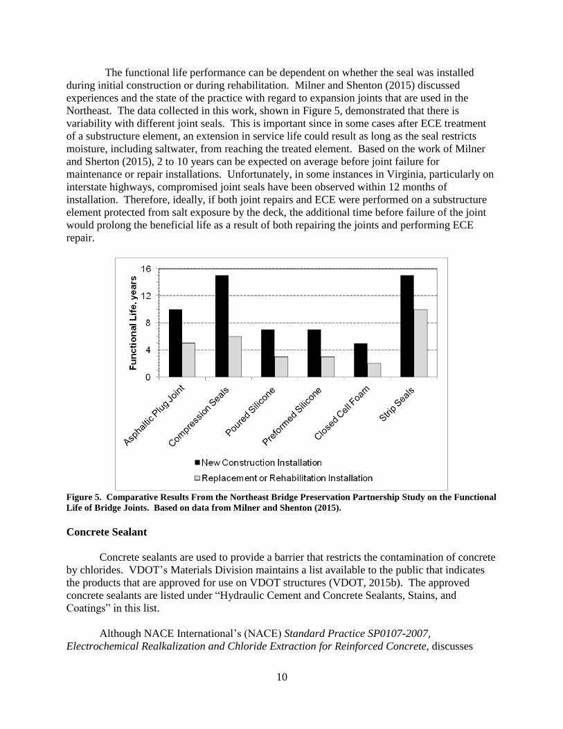
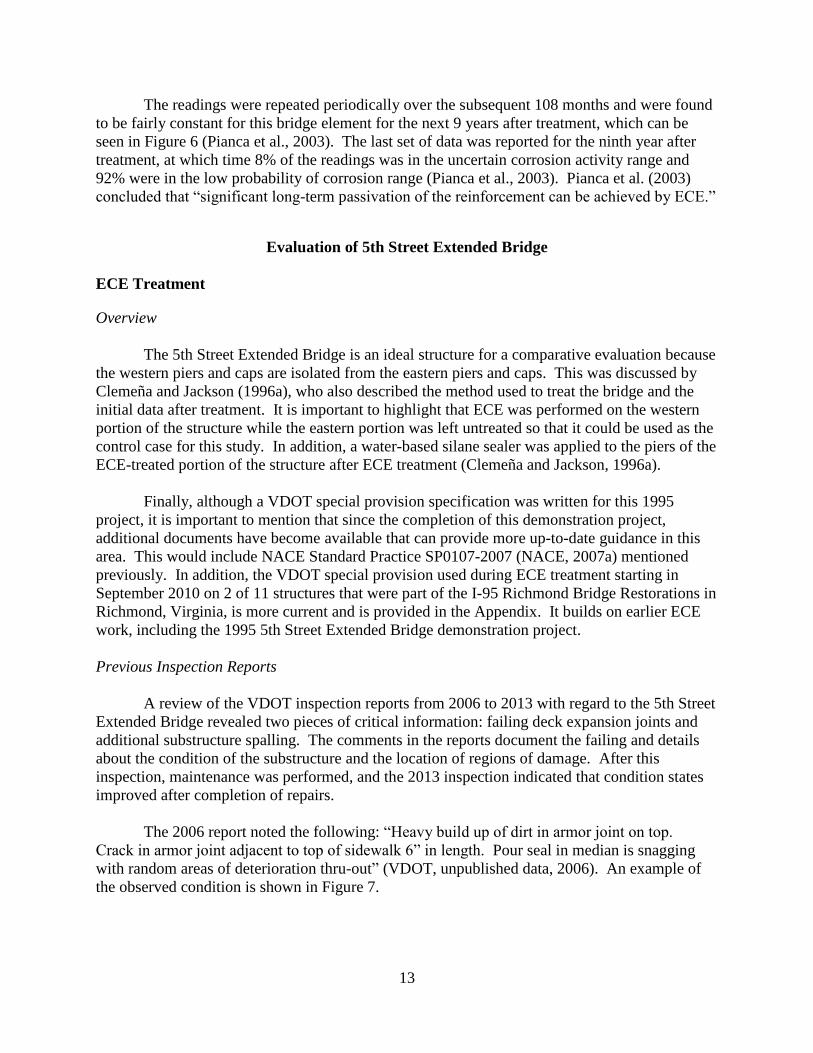
The 2006 report noted the following: “Heavy build up of dirt in armor joint on top.
Crack in armor joint adjacent to top of sidewalk 6” in length. Pour seal in median is snagging
with random areas of deterioration thru-out” (VDOT, unpublished data, 2006). An example of
the observed condition is shown in Figure 7.
14
Figure 7. Photograph From VDOT Inspection Report. The report stated: "Note heavy deterioration of joint
seal & spalling along the edges of longitudinal joint in median" (VDOT, unpublished data, 2006).
The 2008 report noted the following: “leaking and damage joints” and “joints are leaking
over piers, abutments and median” (VDOT, unpublished data, 2008). The 2010 and 2012 reports
continued to support these assertions: “All joints are leaking over piers and abutments including
the median seal” (VDOT, unpublished data, 2010; 2012). All of this information indicates that
since at least 2008, the piers have not benefited from having a deck with working joints to
provide protection from the elements.
The substructure in 2012 was considered to be in satisfactory condition and was assigned
a condition rating of 6, which was the same rating as in 2008 and 2010 (VDOT, unpublished
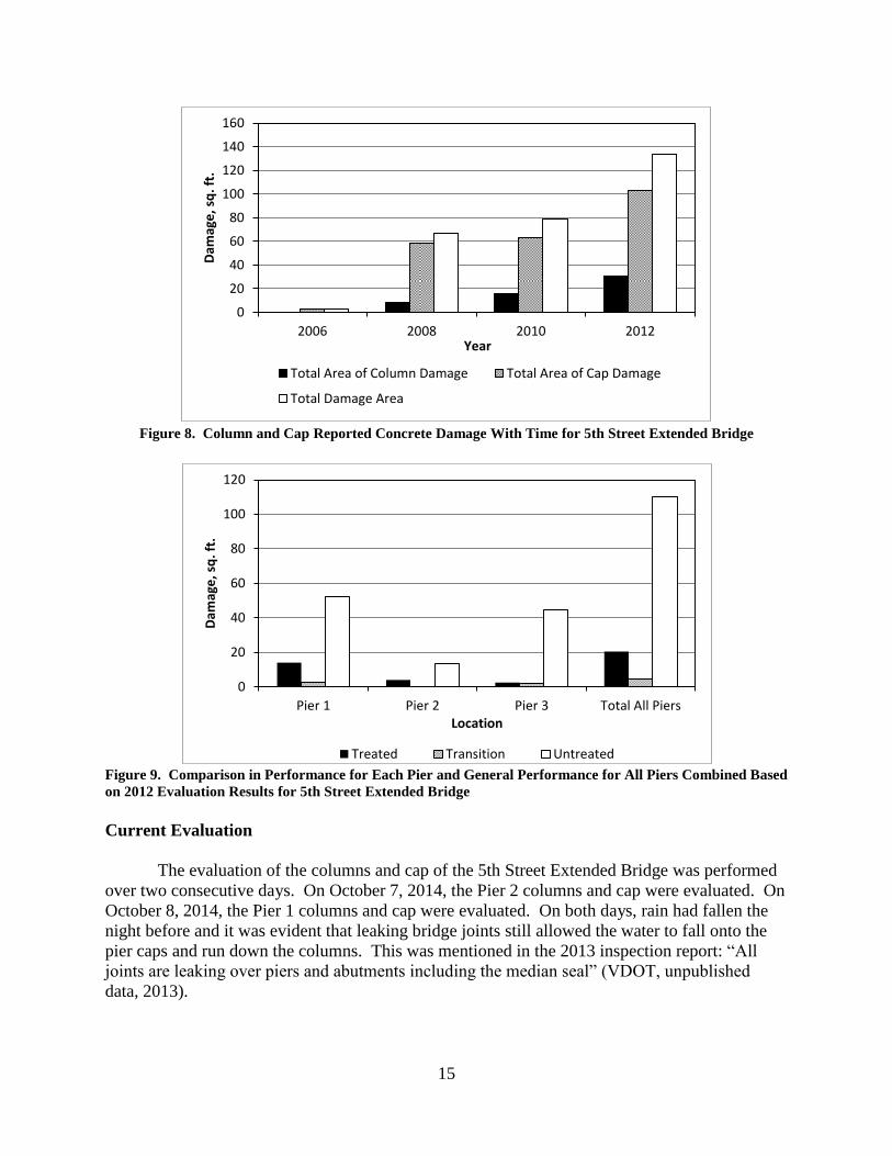
data, 2008; 2010; 2012). With the 2006, 2008, 2010, and 2012 data, the total amount of
delaminated or spalled areas on the column or cap were plotted to allow a better understanding of
the change in condition of these bridge elements with time (Figure 8). It is clear that the cap
exhibited the greater degree of damage when compared to the column. This could be because
the cap protects the underlying column from moisture leaking down on the cap through the
damaged joints.
Not all of the inspection reports provide detailed information to determine precisely
where delamination or spalling was found during the inspection. The 2012 inspection report,
however, provided ample information to determine if the repair area was in the treated or
untreated area. Therefore, this report was used to evaluate how well the treatment was working
after 18 years of exposure. Clearly, the untreated areas showed a greater quantity of damage
when compared to the treated regions (Figure 9). Even if the transition region (the damaged area
of the piers where the break between columns occurs that separate the treated and untreated cap
regions) is added to the damaged area on the treated side of the structure, the untreated damage
area is still larger. Overall, comparing the damage in treated and untreated areas, the untreated
area exhibited more than 5 times the damage of the ECE-treated and sealed area.
15
Figure 8. Column and Cap Reported Concrete Damage With Time for 5th Street Extended Bridge
Figure 9. Comparison in Performance for Each Pier and General Performance for All Piers Combined Based
on 2012 Evaluation Results for 5th Street Extended Bridge
Current Evaluation
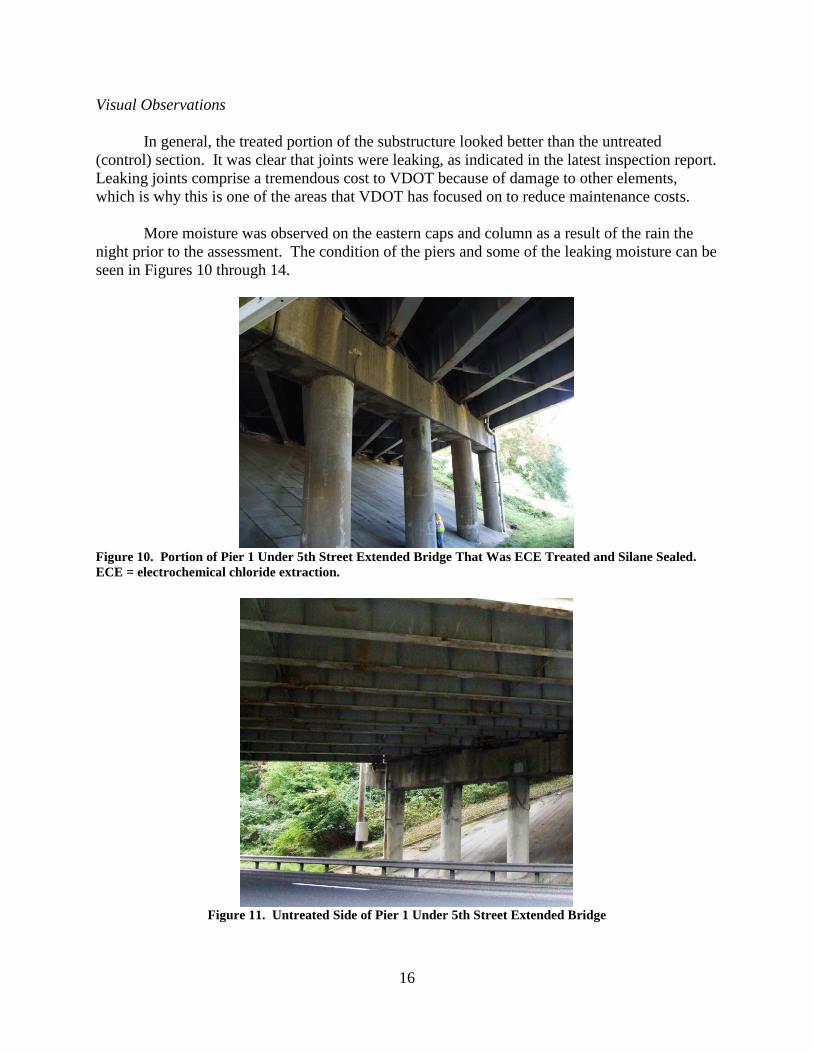
The evaluation of the columns and cap of the 5th Street Extended Bridge was performed
over two consecutive days. On October 7, 2014, the Pier 2 columns and cap were evaluated. On
October 8, 2014, the Pier 1 columns and cap were evaluated. On both days, rain had fallen the
night before and it was evident that leaking bridge joints still allowed the water to fall onto the
pier caps and run down the columns. This was mentioned in the 2013 inspection report: “All
joints are leaking over piers and abutments including the median seal” (VDOT, unpublished
data, 2013).
0
20
40
60
80
100
120
140
160
2006 2008 2010 2012
Dam
age
, sq
. ft.
Year
Total Area of Column Damage Total Area of Cap Damage
Total Damage Area
0
20
40
60
80
100
120
Pier 1 Pier 2 Pier 3 Total All Piers
Dam
age
, sq
. ft.
Location
Treated Transition Untreated
16
Visual Observations
In general, the treated portion of the substructure looked better than the untreated
(control) section. It was clear that joints were leaking, as indicated in the latest inspection report.
Leaking joints comprise a tremendous cost to VDOT because of damage to other elements,
which is why this is one of the areas that VDOT has focused on to reduce maintenance costs.
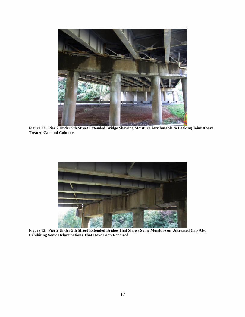
More moisture was observed on the eastern caps and column as a result of the rain the
night prior to the assessment. The condition of the piers and some of the leaking moisture can be
seen in Figures 10 through 14.
Figure 10. Portion of Pier 1 Under 5th Street Extended Bridge That Was ECE Treated and Silane Sealed.
ECE = electrochemical chloride extraction.
Figure 11. Untreated Side of Pier 1 Under 5th Street Extended Bridge
17
Figure 12. Pier 2 Under 5th Street Extended Bridge Showing Moisture Attributable to Leaking Joint Above
Treated Cap and Columns
Figure 13. Pier 2 Under 5th Street Extended Bridge That Shows Some Moisture on Untreated Cap Also
Exhibiting Some Delaminations That Have Been Repaired

18
Figure 14. Pier 3 Columns Under 5th Street Extended Bridge: Left 3 columns treated with ECE and sealed; 4
right columns served as control (untreated and not sealed). ECE = electrochemical chloride extraction.
Chloride Concentrations
On Pier 2, which is located between the eastbound and westbound lanes of traffic, a
higher concentration of chlorides was found for the untreated columns than for the treated
columns. This can be seen in Figure 15, which shows that for both the interior and exterior of
the untreated columns, the surface and subsequent sample depths had higher chloride
concentrations than Column 1, which was treated. This would be expected if ECE and the
sealing of the surface were effective, since the ECE treatment would have lowered the
concentration of chlorides and the sealing of the piers would have restricted new chlorides from
entering the concrete.
Figure 15. Pier 2 of 5th Street Extended Bridge Showing Chloride Concentrations in Treated and Untreated
Columns After 19 Years. Figure 4 shows interior location, indicated by “I,” and exterior location, indicated
by “E,” of the pier.
19
Delaminated Areas and Soundness of Repairs
Soundings of Pier 1 and Pier 3 indicated that patches and the surrounding area were
sound. Therefore, no additional damage, including any damage associated with the halo effect,
has been detected since the last set of repairs.
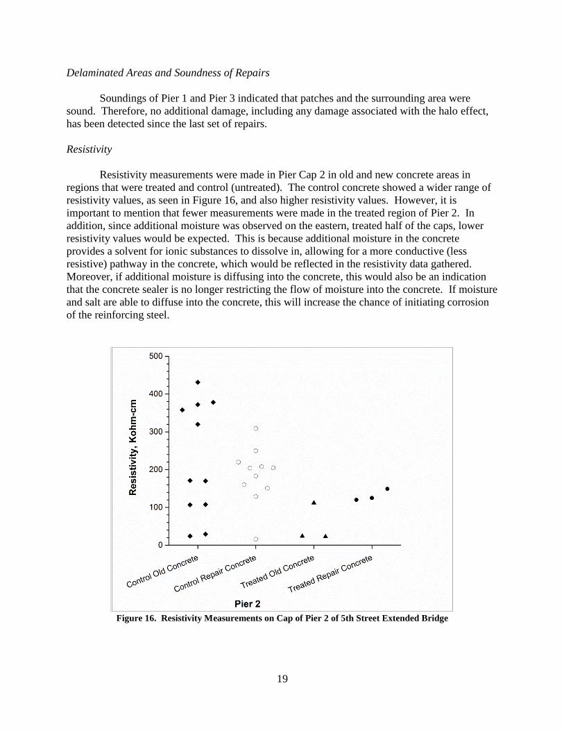
Resistivity
Resistivity measurements were made in Pier Cap 2 in old and new concrete areas in
regions that were treated and control (untreated). The control concrete showed a wider range of
resistivity values, as seen in Figure 16, and also higher resistivity values. However, it is
important to mention that fewer measurements were made in the treated region of Pier 2. In
addition, since additional moisture was observed on the eastern, treated half of the caps, lower
resistivity values would be expected. This is because additional moisture in the concrete
provides a solvent for ionic substances to dissolve in, allowing for a more conductive (less
resistive) pathway in the concrete, which would be reflected in the resistivity data gathered.
Moreover, if additional moisture is diffusing into the concrete, this would also be an indication
that the concrete sealer is no longer restricting the flow of moisture into the concrete. If moisture
and salt are able to diffuse into the concrete, this will increase the chance of initiating corrosion
of the reinforcing steel.
Figure 16. Resistivity Measurements on Cap of Pier 2 of 5th Street Extended Bridge

20
Since the resistivity of the concrete influences the corrosion susceptibility of embedded
reinforcing steel, some have associated the range in resistivity to the likely corrosion rate. For
example, Broomfield (2007) indicated a low corrosion rate for resistivity values greater than 20
Kohm-cm; A low to moderate corrosion rate for values ranging from 10 to 20 Kohm-cm; a high
corrosion rate for values ranging from 5 to 10 Kohm-cm; and very high corrosion rates for values
less than 5 Kohm-cm. Therefore, based on this ranking, the majority of resistivity measurements
that were made 1 year after the repair of the damaged concrete areas were in the low corrosion
rate range. There are several values that would rank in the low to moderate corrosion rate range,
but these lower values could also be attributable to the proximity of reinforcing steel, which
would increase the conductivity in the area.
Half-cell Potentials
Evaluations of the pier cap ends on the treated and untreated sides of the bridge indicated
a lower probability of corrosion in the treated region as compared to the untreated region of the
piers. Figure 17 shows the half-cell potential measurements, which indicate that the three control
(untreated) caps were exhibiting a more negative electrochemical half-cell potential.
Figure 17. Half-cell Potential Measurements for Treated and Untreated Pier Cap Ends of 5th Street
Extended Bridge

21
Concrete Depth of Cover
The depth of cover measurements were made on the columns that supported each pier
cap. These measurements, shown in Figure 18, indicated some variability in the depth of cover
from pier to pier and within a set of columns on a given pier. The mean depth of cover varied
between 3.0 and 3.5 in, with the Pier 2 treated and control columns having the least variation in
cover depth. The minimum depth of cover was 2.0 in, and the maximum was 4.6 in.
Figure 18. Depth of Cover Measurements on Piers of 5th Street Extended Bridge
Evaluation of I-95 Bridges
Overview
Originally when the work was proposed, all 11 bridges were to have concrete repair
followed by the application of ECE and the installation of a CP system. This recommendation
was challenged by VDOT and a letter was written by the corrosion services consultant in
response to a request made by VDOT to revise the corrosion mitigation approach used for the
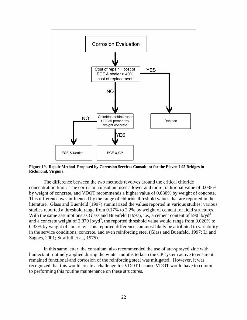
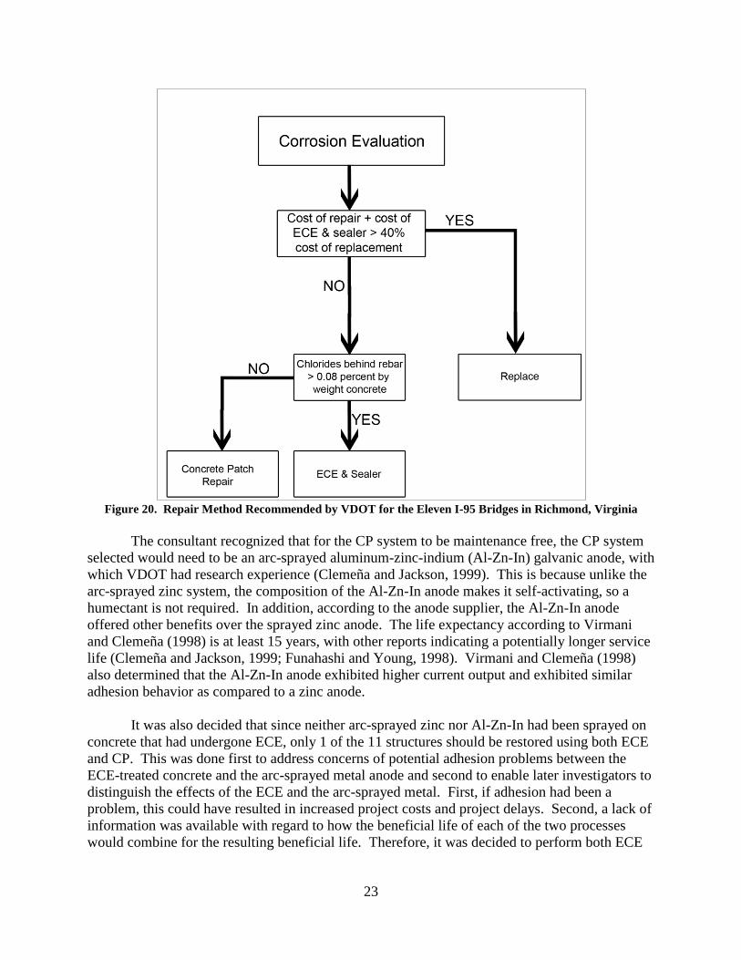
substructures. The consultant’s repair method for the 11 bridges is shown in Figure 19, and
VDOT responded with the proposed decision flowchart shown in Figure 20.
22
Figure 19. Repair Method Proposed by Corrosion Services Consultant for the Eleven I-95 Bridges in
Richmond, Virginia
The difference between the two methods revolves around the critical chloride
concentration limit. The corrosion consultant uses a lower and more traditional value of 0.035%
by weight of concrete, and VDOT recommends a higher value of 0.080% by weight of concrete.
This difference was influenced by the range of chloride threshold values that are reported in the
literature. Glass and Buenfeld (1997) summarized the values reported in various studies; various
studies reported a threshold range from 0.17% to 2.2% by weight of cement for field structures.
With the same assumptions as Glass and Buenfeld (1997), i.e., a cement content of 590 lb/yd3
and a concrete weight of 3,879 lb/yd3, the reported threshold value would range from 0.026% to
0.33% by weight of concrete. This reported difference can most likely be attributed to variability
in the service conditions, concrete, and even reinforcing steel (Glass and Buenfeld, 1997; Li and
Sagues, 2001; Stratfull et al., 1975).
In this same letter, the consultant also recommended the use of arc-sprayed zinc with
humectant routinely applied during the winter months to keep the CP system active to ensure it
remained functional and corrosion of the reinforcing steel was mitigated. However, it was
recognized that this would create a challenge for VDOT because VDOT would have to commit
to performing this routine maintenance on these structures.
23
Figure 20. Repair Method Recommended by VDOT for the Eleven I-95 Bridges in Richmond, Virginia
The consultant recognized that for the CP system to be maintenance free, the CP system
selected would need to be an arc-sprayed aluminum-zinc-indium (Al-Zn-In) galvanic anode, with
which VDOT had research experience (Clemeña and Jackson, 1999). This is because unlike the
arc-sprayed zinc system, the composition of the Al-Zn-In anode makes it self-activating, so a
humectant is not required. In addition, according to the anode supplier, the Al-Zn-In anode
offered other benefits over the sprayed zinc anode. The life expectancy according to Virmani
and Clemeña (1998) is at least 15 years, with other reports indicating a potentially longer service
life (Clemeña and Jackson, 1999; Funahashi and Young, 1998). Virmani and Clemeña (1998)
also determined that the Al-Zn-In anode exhibited higher current output and exhibited similar
adhesion behavior as compared to a zinc anode.
It was also decided that since neither arc-sprayed zinc nor Al-Zn-In had been sprayed on
concrete that had undergone ECE, only 1 of the 11 structures should be restored using both ECE
and CP. This was done first to address concerns of potential adhesion problems between the
ECE-treated concrete and the arc-sprayed metal anode and second to enable later investigators to
distinguish the effects of the ECE and the arc-sprayed metal. First, if adhesion had been a
problem, this could have resulted in increased project costs and project delays. Second, a lack of
information was available with regard to how the beneficial life of each of the two processes
would combine for the resulting beneficial life. Therefore, it was decided to perform both ECE

24
and CP on one bridge, the I-95 bridge over Hermitage Road, and only ECE on a second bridge,
the I-95 bridge over Overbrook Road.
After the necessary contract documents were completed, the project was advertised and
bids were submitted. One of the bids was selected, and the work was initiated in September
2010. Table 1 lists all 11 structures, their functions, and the type of corrosion mitigation
treatment each received.
As indicated in Table 1, either CP or ECE was used on selected bridges. The CP
protection system was a galvanic system that uses an arc-spray applied Al-Zn-In anode. For this
project, the Al-Zn-In anode material cost was $6/ft2 and the installation using the arc spray
process ranged from $18/ft2
to 20/ft2
for a total applied cost of $24/ft2 to $26/ft
2. Project
specifications required the indium concentration to be 0.2%. On the bridge that crosses over
Hermitage Road, both ECE and CP were used. This novel approach was proposed as a means to
extend the service life beyond that gained by only ECE (Overbrook Road) or only CP (other 9
bridges listed in Table 1). The associated anode costs varied slightly from those originally used
to estimate the most cost-effective bridge restoration method. The original CP repair cost
numbers, as well as other estimated repair costs, are provided in Table 2. These numbers were
used to determine whether the cost of repair and remediation was a more acceptable option as
compared to the cost of replacement of the damaged member. It was determined that if the cost
of repair was greater than 40% of the cost of replacement, it would be more cost-effective to
replace the member.
Table 1. The Eleven I-95 Bridges in the VDOT Project
Name
Description
Year
Built
Superstructure
Replacement Dates
Substructure
Mitigation
Technique
Upham Brook
(Northbound)
Bridge crosses over Upham Brook
Waterway
1962 Nov. 2013- June 2014 CP
Upham Brook
(Southbound)
Bridge crosses over Upham Brook
Waterway
1962 Nov. 2013-June 2014 CP
Laburnum Avenue Bridge crosses over Laburnum
Avenue
1958 Oct. 2011-April 2012 CP
Westwood Avenue Bridge Crosses over Westwood
Avenue
1958 Southbound June 2012
Northbound Oct. 2012
CP
I-95 South Ramp to
Boulevard
Ramp connects I-95 to Boulevard 1958 Southbound May 2012
Northbound Sept. 2012
CP
Boulevard Bridge crosses over Boulevard 1958 Southbound June 2012
Northbound Aug. 2012
CP
Hermitage Road Bridge crosses over Hermitage
Road
1958 Southbound July 2012
Northbound Sept. 2012
ECE and CP
Robin Hood Road Bridge crosses over Robin Hood
Road
1958 Southbound Nov. 2012
Northbound April 2013
CP
Sherwood Avenue Bridge crosses over Sherwood
Avenue
1958 Southbound Nov. 2012
Northbound April 2013
CP
Overbrook Road Bridge crosses over Overbrook
Road
1958 March 2013 ECE
Lombardy Street Bridge crosses over Lombardy
Street and the CSX Railroad
1958 May-Oct.2013 CP
Source: VDOT (2015a).
CP = cathodic protection; ECE = electrochemical chloride extraction.
25
Table 2. Estimated Repair Cost for I-95 Bridge Replacement for Damaged Member
Description Amount, $ Unit
Concrete repair 900 yd3
ECE treatment 30 ft2
CP 16 ft2
Graffiti-resistant sealant 2 ft2
Pier cap replacement 4,630 ft
Column replacements (in conjunction with pier cap replacements) 1,135 yd3
ECE = electrochemical chloride extraction; CP = cathodic protection.
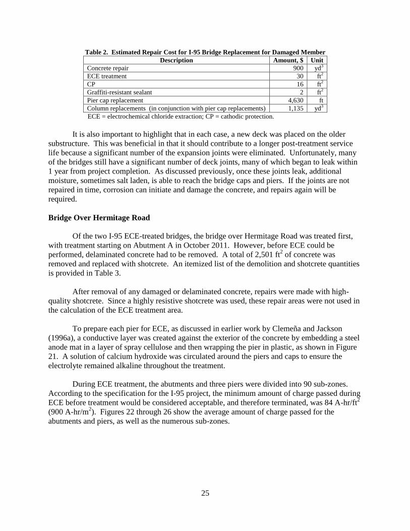
It is also important to highlight that in each case, a new deck was placed on the older
substructure. This was beneficial in that it should contribute to a longer post-treatment service
life because a significant number of the expansion joints were eliminated. Unfortunately, many
of the bridges still have a significant number of deck joints, many of which began to leak within
1 year from project completion. As discussed previously, once these joints leak, additional
moisture, sometimes salt laden, is able to reach the bridge caps and piers. If the joints are not
repaired in time, corrosion can initiate and damage the concrete, and repairs again will be
required.
Bridge Over Hermitage Road
Of the two I-95 ECE-treated bridges, the bridge over Hermitage Road was treated first,
with treatment starting on Abutment A in October 2011. However, before ECE could be
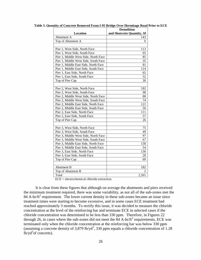
performed, delaminated concrete had to be removed. A total of 2,501 ft2 of concrete was
removed and replaced with shotcrete. An itemized list of the demolition and shotcrete quantities
is provided in Table 3.
After removal of any damaged or delaminated concrete, repairs were made with high-
quality shotcrete. Since a highly resistive shotcrete was used, these repair areas were not used in
the calculation of the ECE treatment area.
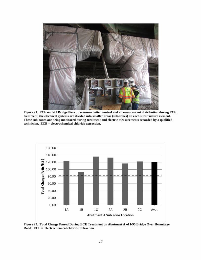
To prepare each pier for ECE, as discussed in earlier work by Clemeña and Jackson
(1996a), a conductive layer was created against the exterior of the concrete by embedding a steel
anode mat in a layer of spray cellulose and then wrapping the pier in plastic, as shown in Figure
21. A solution of calcium hydroxide was circulated around the piers and caps to ensure the
electrolyte remained alkaline throughout the treatment.
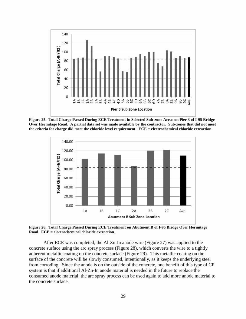
During ECE treatment, the abutments and three piers were divided into 90 sub-zones.
According to the specification for the I-95 project, the minimum amount of charge passed during
ECE before treatment would be considered acceptable, and therefore terminated, was 84 A-hr/ft2
(900 A-hr/m2). Figures 22 through 26 show the average amount of charge passed for the
abutments and piers, as well as the numerous sub-zones.
26
Table 3. Quantity of Concrete Removed From I-95 Bridge Over Hermitage Road Prior to ECE
Location
Demolition
and Shotcrete Quantity, Sf
Abutment A 143
Top of Abutment A 0
Pier 1, West Side, North Face 113
Pier 1, West Side, South Face 65
Pier 1, Middle West Side, North Face 85
Pier 1, Middle West Side, South Face 35
Pier 1, Middle East Side, North Face 81
Pier 1, Middle East Side, South Face 114
Pier 1, East Side, North Face 65
Pier 1, East Side, South Face 52
Top of Pier Cap 30
Pier 2, West Side, North Face 182
Pier 2, West Side, South Face 98
Pier 2, Middle West Side, North Face 88
Pier 2, Middle West Side, South Face 74
Pier 2, Middle East Side, North Face 121
Pier 2, Middle East Side, South Face 50
Pier 2, East Side, North Face 111
Pier 2, East Side, South Face 57
Top of Pier Cap 26
Pier 3, West Side, North Face 75
Pier 3, West Side, South Face 49
Pier 3, Middle West Side, North Face 97
Pier 3, Middle West Side, South Face 67
Pier 3, Middle East Side, North Face 158
Pier 3, Middle East Side, South Face 54
Pier 3, East Side, North Face 130
Pier 3, East Side, South Face 28
Top of Pier Cap 69
Abutment B 182
Top of Abutment B 2
Total 2,501
ECE = electrochemical chloride extraction.
It is clear from these figures that although on average the abutments and piers received
the minimum treatment required, there was some variability, as not all of the sub-zones met the
84 A-hr/ft2 requirement. The lower current density in these sub-zones became an issue since
treatment times were starting to become excessive, and in some cases ECE treatment had
reached approximately 3 months. To rectify this issue, it was decided to measure the chloride
concentration at the level of the reinforcing bar and terminate ECE in selected cases if the
chloride concentration was determined to be less than 330 ppm. Therefore, in Figures 22
through 26, in cases where the sub-zones did not meet the 84 A-hr/ft2 requirements, ECE was
terminated only when the chloride concentration at the reinforcing bar was below 330 ppm
(assuming a concrete density of 3,879 lb/yd3, 330 ppm equals a chloride concentration of 1.28
lb/yd3of concrete).
27
Figure 21. ECE on I-95 Bridge Piers. To ensure better control and an even current distribution during ECE
treatment, the electrical systems are divided into smaller areas (sub-zones) on each substructure element.
These sub-zones are being monitored during treatment and electric measurements recorded by a qualified
technician. ECE = electrochemical chloride extraction.
Figure 22. Total Charge Passed During ECE Treatment on Abutment A of I-95 Bridge Over Hermitage
Road. ECE = electrochemical chloride extraction.

28
Figure 23. Total Charge Passed During ECE Treatment on Pier 1 of I-95 Bridge Over Hermitage Road.
Sub-zones that did not meet the criteria for charge did meet the chloride level requirement. ECE =
electrochemical chloride extraction.
Figure 24. Total Charge Passed During ECE Treatment on Pier 2 of I-95 Bridge Over Hermitage Road.
Sub-zones that did not meet the criteria for charge did meet the chloride level requirement. ECE =
electrochemical chloride extraction.
29
Figure 25. Total Charge Passed During ECE Treatment in Selected Sub-zone Areas on Pier 3 of I-95 Bridge
Over Hermitage Road. A partial data set was made available by the contractor. Sub-zones that did not meet
the criteria for charge did meet the chloride level requirement. ECE = electrochemical chloride extraction.
Figure 26. Total Charge Passed During ECE Treatment on Abutment B of I-95 Bridge Over Hermitage
Road. ECE = electrochemical chloride extraction.
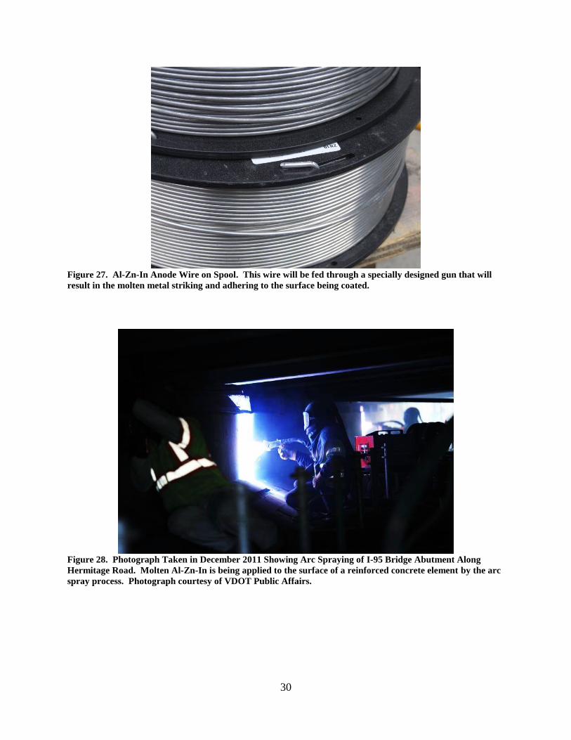
After ECE was completed, the Al-Zn-In anode wire (Figure 27) was applied to the
concrete surface using the arc spray process (Figure 28), which converts the wire to a tightly
adherent metallic coating on the concrete surface (Figure 29). This metallic coating on the
surface of the concrete will be slowly consumed, intentionally, as it keeps the underlying steel
from corroding. Since the anode is on the outside of the concrete, one benefit of this type of CP
system is that if additional Al-Zn-In anode material is needed in the future to replace the
consumed anode material, the arc spray process can be used again to add more anode material to
the concrete surface.
30
Figure 27. Al-Zn-In Anode Wire on Spool. This wire will be fed through a specially designed gun that will
result in the molten metal striking and adhering to the surface being coated.
Figure 28. Photograph Taken in December 2011 Showing Arc Spraying of I-95 Bridge Abutment Along
Hermitage Road. Molten Al-Zn-In is being applied to the surface of a reinforced concrete element by the arc
spray process. Photograph courtesy of VDOT Public Affairs.
31
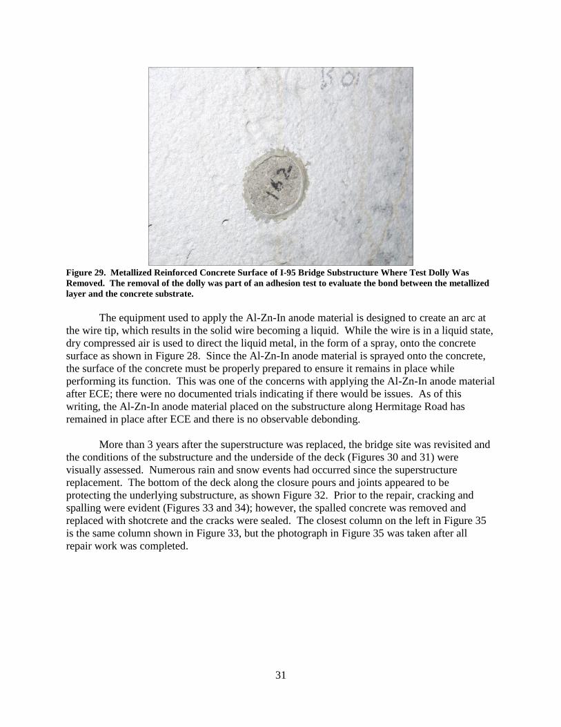
Figure 29. Metallized Reinforced Concrete Surface of I-95 Bridge Substructure Where Test Dolly Was
Removed. The removal of the dolly was part of an adhesion test to evaluate the bond between the metallized
layer and the concrete substrate.
The equipment used to apply the Al-Zn-In anode material is designed to create an arc at
the wire tip, which results in the solid wire becoming a liquid. While the wire is in a liquid state,
dry compressed air is used to direct the liquid metal, in the form of a spray, onto the concrete
surface as shown in Figure 28. Since the Al-Zn-In anode material is sprayed onto the concrete,
the surface of the concrete must be properly prepared to ensure it remains in place while
performing its function. This was one of the concerns with applying the Al-Zn-In anode material
after ECE; there were no documented trials indicating if there would be issues. As of this
writing, the Al-Zn-In anode material placed on the substructure along Hermitage Road has
remained in place after ECE and there is no observable debonding.
More than 3 years after the superstructure was replaced, the bridge site was revisited and
the conditions of the substructure and the underside of the deck (Figures 30 and 31) were
visually assessed. Numerous rain and snow events had occurred since the superstructure
replacement. The bottom of the deck along the closure pours and joints appeared to be
protecting the underlying substructure, as shown Figure 32. Prior to the repair, cracking and
spalling were evident (Figures 33 and 34); however, the spalled concrete was removed and
replaced with shotcrete and the cracks were sealed. The closest column on the left in Figure 35
is the same column shown in Figure 33, but the photograph in Figure 35 was taken after all
repair work was completed.

32
Figure 30. Underside of I-95 Bridge Over Hermitage Road Showing Beams, Diaphragms, and Joints After
Superstructure Replacement Was Completed
Figure 31. Underside of I-95 Bridge Over Hermitage Road Showing Post-Tensioning Termination Points
After Superstructure Replacement Was Completed. No leaking joints were observed.
33
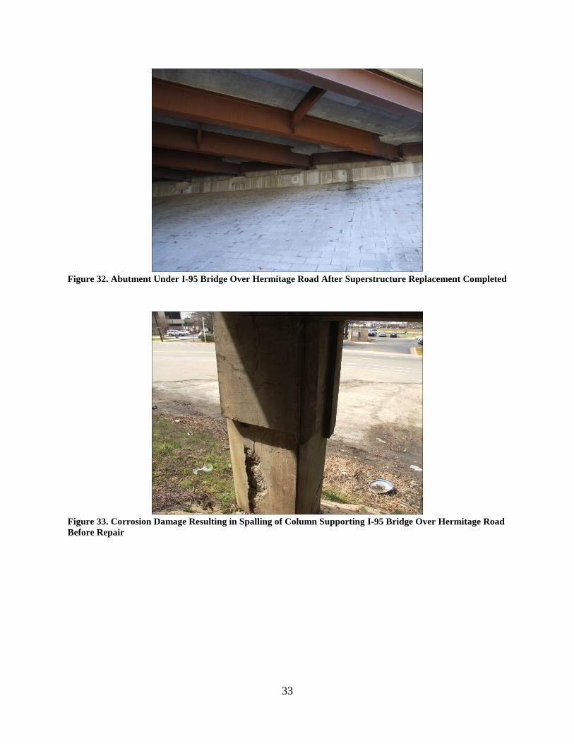
Figure 32. Abutment Under I-95 Bridge Over Hermitage Road After Superstructure Replacement Completed
Figure 33. Corrosion Damage Resulting in Spalling of Column Supporting I-95 Bridge Over Hermitage Road
Before Repair
34
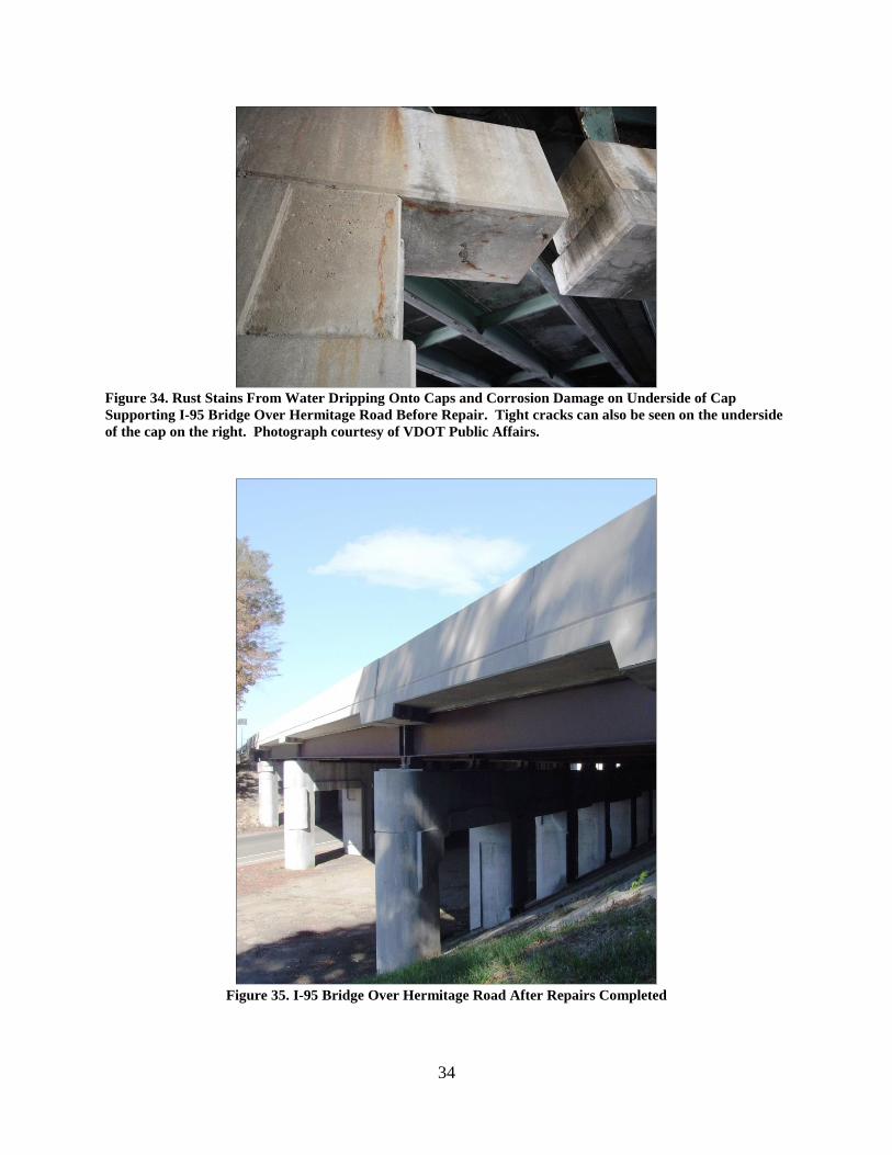
Figure 34. Rust Stains From Water Dripping Onto Caps and Corrosion Damage on Underside of Cap
Supporting I-95 Bridge Over Hermitage Road Before Repair. Tight cracks can also be seen on the underside
of the cap on the right. Photograph courtesy of VDOT Public Affairs.
Figure 35. I-95 Bridge Over Hermitage Road After Repairs Completed
35
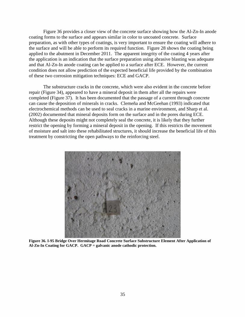
Figure 36 provides a closer view of the concrete surface showing how the Al-Zn-In anode
coating forms to the surface and appears similar in color to uncoated concrete. Surface
preparation, as with other types of coatings, is very important to ensure the coating will adhere to
the surface and will be able to perform its required function. Figure 28 shows the coating being
applied to the abutment in December 2011. The apparent integrity of the coating 4 years after
the application is an indication that the surface preparation using abrasive blasting was adequate
and that Al-Zn-In anode coating can be applied to a surface after ECE. However, the current
condition does not allow prediction of the expected beneficial life provided by the combination
of these two corrosion mitigation techniques: ECE and GACP.
The substructure cracks in the concrete, which were also evident in the concrete before
repair (Figure 34), appeared to have a mineral deposit in them after all the repairs were
completed (Figure 37). It has been documented that the passage of a current through concrete
can cause the deposition of minerals in cracks. Clemeña and McGeehan (1993) indicated that
electrochemical methods can be used to seal cracks in a marine environment, and Sharp et al.
(2002) documented that mineral deposits form on the surface and in the pores during ECE.
Although these deposits might not completely seal the concrete, it is likely that they further
restrict the opening by forming a mineral deposit in the opening. If this restricts the movement
of moisture and salt into these rehabilitated structures, it should increase the beneficial life of this
treatment by constricting the open pathways to the reinforcing steel.
Figure 36. I-95 Bridge Over Hermitage Road Concrete Surface Substructure Element After Application of
Al-Zn-In Coating for GACP. GACP = galvanic anode cathodic protection.

36
Figure 37. Previously Existing Crack in Concrete Exhibits Mineral Deposit, Possibly Forming During ECE
Treatment of I-95 Bridge Over Hermitage Road. ECE = electrochemical chloride extraction.
Overall, the piers and abutment of the I-95 bridge over Hermitage Road appear to be in
good condition. A reasonable recommendation would be that every 5 years from the date of
treatment, the reinforced concrete should be evaluated to determine the condition of the GACP
system and if corrosion has started to initiate in these reinforced concrete elements. This will
increase the likelihood that if corrosion initiates again, it will be detected before it becomes
apparent through cracking and spalling of the concrete.
To evaluate the condition of the GACP system that was installed after ECE, monitoring
zones were incorporated into the GACP system at selected locations. In these areas, the anode
can be isolated from the reinforcing bar so that the condition of the GACP system can be
assessed.
Bridge Over Overbrook Road
Unlike the I-95 bridge substructure over Hermitage Road, the I-95 bridge substructure
over Overbook Road received only ECE to mitigate the ongoing corrosion of the reinforcing
steel. The substructure prior to mitigation work (Figure 38) exhibited sound concrete in many
areas. This is important if ECE is going to be considered since ECE will not strengthen the
existing concrete. Rather, it halts the corrosion reaction that is taking place. Therefore, it is
important to use ECE in situations where a sufficient amount of sound concrete will remain after
any delaminated concrete has been replaced and cracks have been repaired prior to ECE.
37
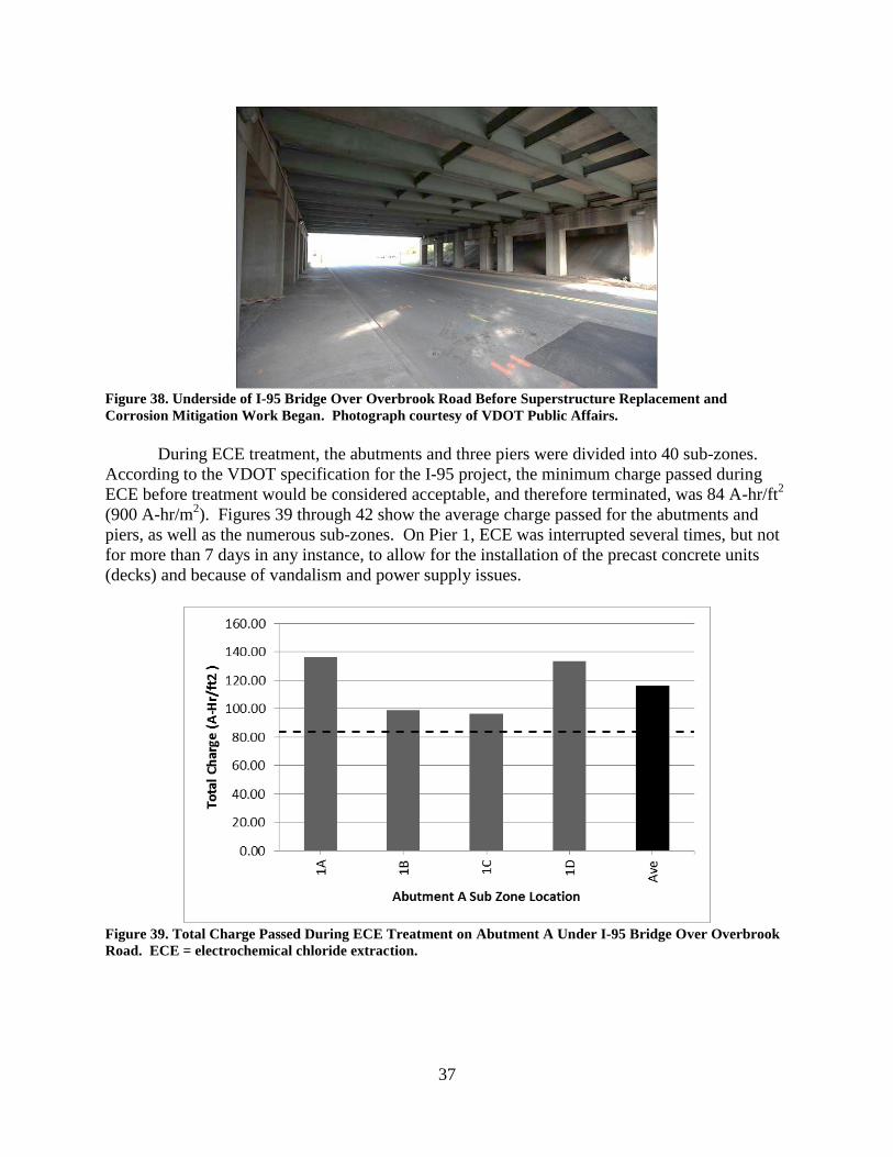
Figure 38. Underside of I-95 Bridge Over Overbrook Road Before Superstructure Replacement and
Corrosion Mitigation Work Began. Photograph courtesy of VDOT Public Affairs.
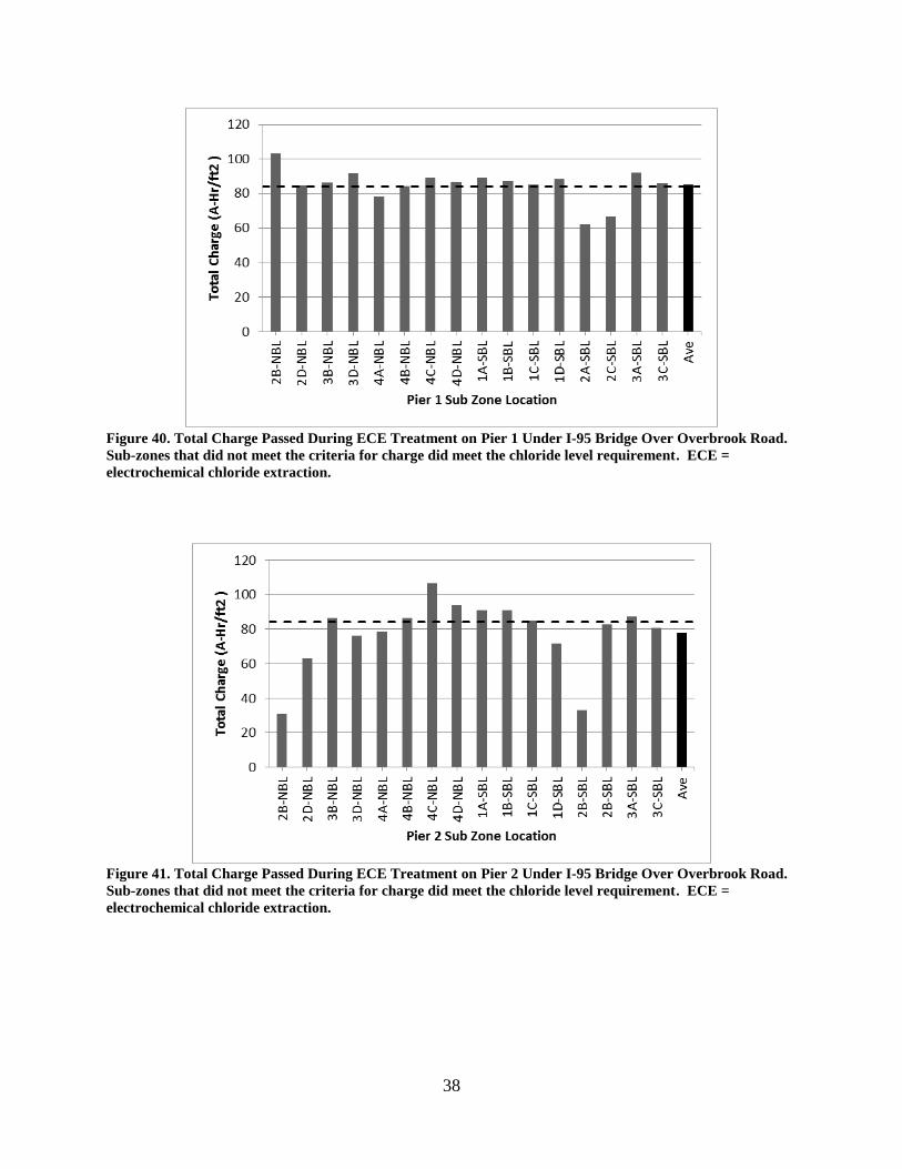
During ECE treatment, the abutments and three piers were divided into 40 sub-zones.
According to the VDOT specification for the I-95 project, the minimum charge passed during
ECE before treatment would be considered acceptable, and therefore terminated, was 84 A-hr/ft2
(900 A-hr/m2). Figures 39 through 42 show the average charge passed for the abutments and
piers, as well as the numerous sub-zones. On Pier 1, ECE was interrupted several times, but not
for more than 7 days in any instance, to allow for the installation of the precast concrete units
(decks) and because of vandalism and power supply issues.
Figure 39. Total Charge Passed During ECE Treatment on Abutment A Under I-95 Bridge Over Overbrook
Road. ECE = electrochemical chloride extraction.
38
Figure 40. Total Charge Passed During ECE Treatment on Pier 1 Under I-95 Bridge Over Overbrook Road.
Sub-zones that did not meet the criteria for charge did meet the chloride level requirement. ECE =
electrochemical chloride extraction.
Figure 41. Total Charge Passed During ECE Treatment on Pier 2 Under I-95 Bridge Over Overbrook Road.
Sub-zones that did not meet the criteria for charge did meet the chloride level requirement. ECE =
electrochemical chloride extraction.
39
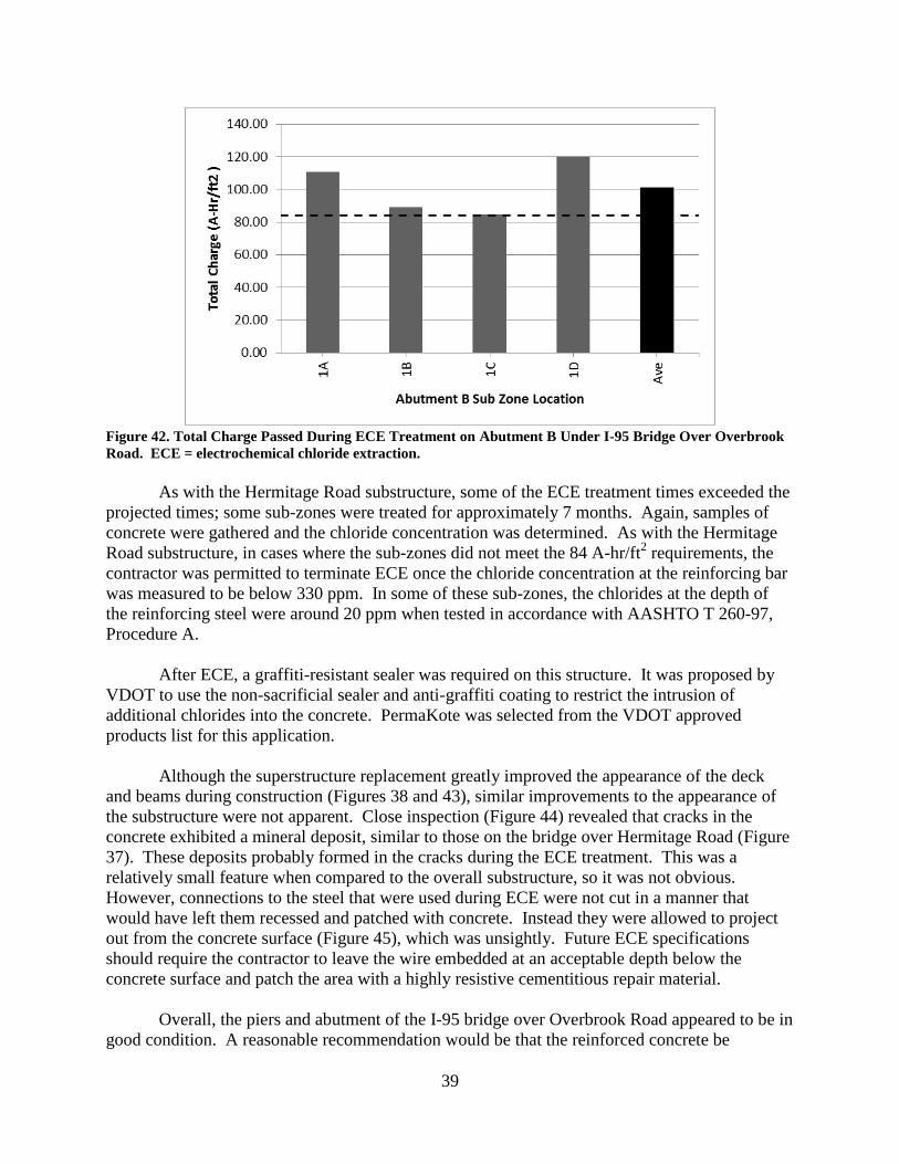
Figure 42. Total Charge Passed During ECE Treatment on Abutment B Under I-95 Bridge Over Overbrook
Road. ECE = electrochemical chloride extraction.
As with the Hermitage Road substructure, some of the ECE treatment times exceeded the
projected times; some sub-zones were treated for approximately 7 months. Again, samples of
concrete were gathered and the chloride concentration was determined. As with the Hermitage
Road substructure, in cases where the sub-zones did not meet the 84 A-hr/ft2 requirements, the
contractor was permitted to terminate ECE once the chloride concentration at the reinforcing bar
was measured to be below 330 ppm. In some of these sub-zones, the chlorides at the depth of
the reinforcing steel were around 20 ppm when tested in accordance with AASHTO T 260-97,
Procedure A.
After ECE, a graffiti-resistant sealer was required on this structure. It was proposed by
VDOT to use the non-sacrificial sealer and anti-graffiti coating to restrict the intrusion of
additional chlorides into the concrete. PermaKote was selected from the VDOT approved
products list for this application.
Although the superstructure replacement greatly improved the appearance of the deck
and beams during construction (Figures 38 and 43), similar improvements to the appearance of
the substructure were not apparent. Close inspection (Figure 44) revealed that cracks in the
concrete exhibited a mineral deposit, similar to those on the bridge over Hermitage Road (Figure
37). These deposits probably formed in the cracks during the ECE treatment. This was a
relatively small feature when compared to the overall substructure, so it was not obvious.
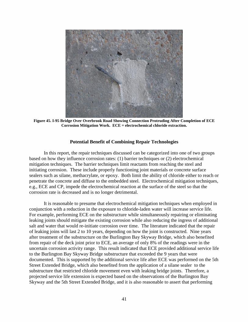
However, connections to the steel that were used during ECE were not cut in a manner that
would have left them recessed and patched with concrete. Instead they were allowed to project
out from the concrete surface (Figure 45), which was unsightly. Future ECE specifications
should require the contractor to leave the wire embedded at an acceptable depth below the
concrete surface and patch the area with a highly resistive cementitious repair material.
Overall, the piers and abutment of the I-95 bridge over Overbrook Road appeared to be in
good condition. A reasonable recommendation would be that the reinforced concrete be

40
evaluated every 5 years from the date of treatment using electrochemical testing, such as the
half-cell potential method, in conjunction with a delamination survey and chloride analysis of the
concrete. This should be done to capture routinely the condition of the reinforced concrete and
to determine if corrosion has started to initiate in these reinforced concrete elements. This would
increase the likelihood that if corrosion initiated again, it would most likely be detected as the
corrosion began, i.e., before it became apparent through cracking and spalling of the concrete.
Figure 43. I-95 Bridge Over Overbrook Road Showing Underside After Completion of Project
Figure 44. I-95 Bridge Over Overbrook Road Showing Mineral Deposit on Column After ECE. ECE =
electrochemical chloride extraction.
41
Figure 45. I-95 Bridge Over Overbrook Road Showing Connection Protruding After Completion of ECE
Corrosion Mitigation Work. ECE = electrochemical chloride extraction.
Potential Benefit of Combining Repair Technologies
In this report, the repair techniques discussed can be categorized into one of two groups
based on how they influence corrosion rates: (1) barrier techniques or (2) electrochemical
mitigation techniques. The barrier techniques limit reactants from reaching the steel and
initiating corrosion. These include properly functioning joint materials or concrete surface
sealers such as silane, methacrylate, or epoxy. Both limit the ability of chloride either to reach or
penetrate the concrete and diffuse to the embedded steel. Electrochemical mitigation techniques,
e.g., ECE and CP, impede the electrochemical reaction at the surface of the steel so that the
corrosion rate is decreased and is no longer detrimental.
It is reasonable to presume that electrochemical mitigation techniques when employed in
conjunction with a reduction in the exposure to chloride-laden water will increase service life.
For example, performing ECE on the substructure while simultaneously repairing or eliminating
leaking joints should mitigate the existing corrosion while also reducing the ingress of additional
salt and water that would re-initiate corrosion over time. The literature indicated that the repair
of leaking joins will last 2 to 10 years, depending on how the joint is constructed. Nine years
after treatment of the substructure on the Burlington Bay Skyway Bridge, which also benefited
from repair of the deck joint prior to ECE, an average of only 8% of the readings were in the
uncertain corrosion activity range. This result indicated that ECE provided additional service life
to the Burlington Bay Skyway Bridge substructure that exceeded the 9 years that were
documented. This is supported by the additional service life after ECE was performed on the 5th
Street Extended Bridge, which also benefited from the application of a silane sealer to the
substructure that restricted chloride movement even with leaking bridge joints. Therefore, a
projected service life extension is expected based on the observations of the Burlington Bay
Skyway and the 5th Street Extended Bridge, and it is also reasonable to assert that performing
42
measures to restrict the reintroduction of chloride into the concrete will further extend the service
life of a structure.
Moreover, a second assertion, increasing service life by combining electrochemical
techniques, has also been suggested by some consultants, as in the case of the I-95 bridges
project, which combined several electrochemical corrosion mitigation techniques to increase
service life beyond what a single technique would provide. Therefore, the reported additional
service life with the use of Al-Zn-In as part of a GACP system is 15 to 20 years, or ECE with a
sealer can reasonably add 15 to 20 years of additional service life for the substructure. However,
this second assertion is more difficult to quantify for two reasons: (1) it is not clear how the
beneficial life of each electrochemical mitigation technique combines to increase the total service
life, and (2) ECE is a relatively new method with reinforced concrete structures, so historic data
are limited. In addition, there are sometimes questions with regard to the feasibility of
combining two mitigation techniques, especially on large projects when historical documentation
does not exist for trial studies or smaller projects.
As discussed previously, there were concerns with metallizing numerous bridge
substructures along I-95 after ECE treatment when there was no record of it ever being
attempted. Problems with adhesion between the Al-Zn-In galvanic anode and the concrete after
ECE, however, were not detected. Quality control testing during the metallizing operation on the
substructure of the I-95 bridge over Hermitage Road indicated that the coating was bonding.
Visual inspection of the substructure 4 years later further confirmed that the coating can be
applied to a surface after ECE.
A Pessimistic Model of Combined Benefits
The most pessimistic set of assumptions is as follows:
1. that each treatment individually is an effective defense against corrosion for as long
as it continues to function
2. that no treatment prolongs the functional life of any of the other treatments
3. that corrosion is mitigated as long as at least one of these treatments continues to
function and corrosion begins when the last treatment ceases to function.
Under these assumptions, the minimum and maximum duration before the onset of
corrosion would be described by the following equations.
min[duration of A+B+C] = min[min(duration of A), min(duration of B), min(duration of
C)]
max[duration of A+B+C] = max[max(duration of A), max(duration of B), max(duration
of C)].
43
These assumptions amount to saying that there are no additive benefits. The duration of the
effective impact of any number of treatments would be simply the duration of the one treatment
that lasts the longest.
These assumptions are unrealistically conservative for a couple of identifiable reasons.
First, the assumption that any one treatment is an absolutely effective barrier from the
completion of its application until the end of its useful life is unrealistic. Each of the treatments,
even with the most expert application, exhibits a certain amount of spatial lack of uniformity
from one spot to another, and the rate of degradation is somewhat uneven from one spot to
another. A second treatment is almost certain to provide a useful “second line of defense”
somewhere. Second, the assumption that no treatment affects the functional life of any other
treatment is unrealistic. Available evidence, and understanding of the mechanisms at work,
suggests that one treatment can affect the rate of degradation of another treatment. For this
reason, too, a combination of two treatments is likely to have a longer effective life than either
treatment would have by itself.
A More Realistic (But Still Conservative) Estimate of Combined Benefits
A more realistic estimate of the compound benefit of multiple treatments—albeit a more
complicated estimate—may be made by considering (1) the extent to which each treatment’s
effectiveness diminishes with time and (2) the impact that one treatment can have on the rate at
which the effectiveness of another treatment diminishes.
Joint Repair Plus Any Treatment to the Substructure
Deck joints fail by cracking and thereby becoming more permeable to water, which also
transports salt. Degradation of (deck) joint function is probably primarily a function of
construction quality and environmental exposure. No second treatment applied to the
substructure can be expected to augment the life of a joint repair, as the joints block passage of
water and chlorides to the substructure for as long as they function; however, a joint repair can
be expected to prolong the effective life of any substructure treatment.
For the 2 to 10 years that a deck joint repair may be expected to hold up, it is possible
that a concrete surface sealer will deteriorate more slowly than it otherwise would, that the
impact of an ECE may scarcely begin at all, and that an anodic coating will deteriorate more
slowly than it otherwise would. The service life impact of joint repair and the service life impact
of ECE could be completely additive: the “clock” on the benefits of the ECE treatment may
scarcely begin to run until the “clock” on the benefits of the joint repair has run out. Therefore,
this would lead to a beneficial life of 2 to 10 years (joint repair) + 9 to 15 (plus) years (ECE)
= 11 to 25 (plus) years of bridge life extension.
Concrete Surface Sealer Plus ECE
The surface sealer (presumably) fails by becoming permeable as a result of wear or tear.
For as long as it lasts, a surface sealer that coats all surfaces of the concrete substructure (except
perhaps the underside) could largely block the moisture and chlorides that otherwise would
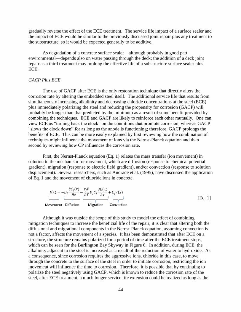
44
gradually reverse the effect of the ECE treatment. The service life impact of a surface sealer and
the impact of ECE would be similar to the previously discussed joint repair plus any treatment to
the substructure, so it would be expected generally to be additive.
As degradation of a concrete surface sealer—although probably in good part
environmental—depends also on water passing through the deck; the addition of a deck joint
repair as a third treatment may prolong the effective life of a substructure surface sealer plus
ECE.
GACP Plus ECE
The use of GACP after ECE is the only restoration technique that directly alters the
corrosion rate by altering the embedded steel itself. The additional service life that results from
simultaneously increasing alkalinity and decreasing chloride concentrations at the steel (ECE)
plus immediately polarizing the steel and reducing the propensity for corrosion (GACP) will
probably be longer than that predicted by the minimum as a result of some benefit provided by
combining the techniques. ECE and GACP are likely to reinforce each other mutually. One can
view ECE as “turning back the clock” on the conditions that promote corrosion, whereas GACP
“slows the clock down” for as long as the anode is functioning; therefore, GACP prolongs the
benefits of ECE. This can be more easily explained by first reviewing how the combination of
techniques might influence the movement of ions via the Nernst-Planck equation and then
second by reviewing how CP influences the corrosion rate.
First, the Nernst-Planck equation (Eq. 1) relates the mass transfer (ion movement) in
solution to the mechanism for movement, which are diffusion (response to chemical potential
gradient), migration (response to electric field gradient), and/or convection (response to solution
displacement). Several researchers, such as Andrade et al. (1995), have discussed the application
of Eq. 1 and the movement of chloride ions in concrete.
[Eq. 1]
Although it was outside the scope of this study to model the effect of combining
mitigation techniques to increase the beneficial life of the repair, it is clear that altering both the
diffusional and migrational components in the Nernst-Planck equation, assuming convection is
not a factor, affects the movement of a species. It has been demonstrated that after ECE on a
structure, the structure remains polarized for a period of time after the ECE treatment stops,
which can be seen for the Burlington Bay Skyway in Figure 6. In addition, during ECE, the
alkalinity adjacent to the steel is increased as a result of the reduction of water to hydroxide. As
a consequence, since corrosion requires the aggressive ions, chloride in this case, to move
through the concrete to the surface of the steel in order to initiate corrosion, restricting the ion
movement will influence the time to corrosion. Therefore, it is possible that by continuing to
polarize the steel negatively using GACP, which is known to reduce the corrosion rate of the
steel, after ECE treatment, a much longer service life extension could be realized as long as the
45
galvanic anode remained active. From the Nernst-Planck equation, it can be concluded that by
applying CP to a reinforced structure after ECE, a polarization effect, although smaller than
during ECE, will remain and so in addition to the diffusional component given in the Nernst-
Planck equation a migrational component will need to be accounted for in the evaluation of the
movement of chloride ions in a structure.
Second, with regard to how the corrosion rate of the reinforced structure is influenced by
CP, as discussed earlier, ECE “turns back the clock” on the conditions that promote corrosion
whereas GACP “slows the clock down” for as long as the anode is functioning. Whereas ECE
will have reduced the chloride ions in the concrete and increased the alkalinity adjacent to the
reinforcing steel, thus reducing the corrosion rate of the steel, the GACP system will slowly
consume the anode while it creates a cathodic current that further slows the dissolution of the
steel in the concrete; therefore, GACP prolongs the benefits of ECE. This interaction implies
that the service life impact of ECE and GACP will be at least partly additive, possibly fully so.
With several restoration techniques used, it is anticipated that additional monitoring of
the I-95 bridges over Hermitage Road and over Overbrook Road will provide a comparison as to
how much longer a GACP system when used after ECE treatment can extend the service life
beyond that of ECE treatment alone. Further, by repairing leaking joints and applying a new
coating of Al-Zn-In in the future, an even greater extension of service life can be obtained.
CONCLUSIONS
Based on the ECE treatment of the substructure of the 5th Street Extended Bridge, additional
years of service life are possible for reinforced concrete that is properly treated with the use
of ECE and a post-treatment sealer.
Elimination or improvement of existing deck joints should be considered when ECE will be
applied to substructure elements to extend the service life after ECE.
The ECE process is often terminated when the “passed charge” exceeds an established
threshold, but difficulties in the field might result in unforeseen construction delays as a
result of the attempt to meet this criterion. Future contracts should establish that the
chloride concentration at the level of the reinforcing bar can be used to set an alternative
criterion in case treatments are lasting excessively long.
Combining electrochemical techniques, such as CP and ECE, is feasible and could
theoretically provide additional life beyond that provided by the use of one of these
techniques alone.
The I-95 bridges over Hermitage Road and over Overbrook Road will provide a comparison
with regard to how much longer a galvanic anode can extend the service life beyond that of
the ECE treatment. In addition, other installations can be used to compare the service life
with GACP and ECE.

46
All ECE connections to the steel should be completely removed or embedded after
completion of the treatment and a highly resistive cementitious repair material should be
used to patch any holes.
RECOMMENDATIONS
1. VDOT’s Structure and Bridge Division, in order to comply with a request by the FHWA, will
work with the Virginia Transportation Research Council (VTRC) to continue to monitor the
I-95 bridges, in particular those over Hermitage Road and Overbrook Road, to determine the
benefit of combining electrochemical corrosion mitigation techniques such as GACP and
ECE and to compare the performance of both techniques.
2. VDOT’s Structure and Bridge Division should include ECE as an option for repair when
extending the service life of existing structures. As part of the repair, a post-treatment sealer
and joint elimination or improvements should be required.
3. VDOT’s Structure and Bridge Division should require that all ECE connections to the steel
be completely removed or embedded after completion of the treatment and that a highly
resistive cementitious repair material be used to patch any holes.
BENEFITS AND IMPLEMENTATION
Benefits
The benefit of monitoring the I-95 bridges, in particular those over Hermitage Road and
Overbrook Road, to determine the benefit of combining electrochemical corrosion mitigation
techniques such as GACP and ECE and to compare the performance of both techniques is that it
will provide VDOT’s Structure and Bridge Division with an understanding of when this
approach is reasonable.
The benefit of including ECE as an option for repair when extending the service life of
existing structures is that it will provide VDOT’s Structure and Bridge Division with the ability
to reduce the amount of concrete repair work required, which could reduce the repair time
needed in certain cases. Another benefit generated by this study is the assertion that as part of
the ECE repair, a post-treatment sealer and joint elimination or improvements should be
required, which will increase the beneficial life of the ECE repair.
There are two benefits of requiring that all ECE connections to the steel be completely
removed or embedded after completion of the treatment and a that highly resistive cementitious
repair material be used to patch any holes. First, this will improve the aesthetics of the repair
while eliminating unnecessary protrusions from the patch. Second, these connections when left
unsealed can provide a pathway for moisture and salt that links directly to the steel.
47
Implementation
VDOT’s Structure and Bridge Division, through its special provisions for corrosion
mitigation services on the I-95 bridges (for example, the Appendix), has agreed with a request by
the FHWA to continue to monitor the I-95 bridges. This will allow a comparison of how much
GACP can extend service life beyond that of ECE treatment alone. VTRC research staff will
assist in this effort.
ACKNOWLEDGMENTS
The author expresses his sincere gratitude to Linda Evans, William Ordel, Ali Akbar
Sohanghpurwala, Siva Venugopalan, David Whitmore, and Jun Zhu. The author also
acknowledges the assistance of the staffs of VDOT’s Central Office, VDOT’s Culpeper District,
VDOT’s Richmond District, and VTRC’s Concrete Laboratory. The author further thanks the
members of the technical review panel for this project: James Gillespie, Jose Gomez, Rodolfo
Maruri, Adam Matteo, Rex Pearce, and Michael Sprinkel.
REFERENCES
Andrade, C., Diez, J.M., Alamán, A., and Alonso, C. Mathematical Modelling of
Electrochemical Chloride Extraction from Concrete. Cement and Concrete Research,
Vol. 25, No. 4, 1995, pp. 727-740.
Andrade, C., Castellote, M., Sarria, J., Alonso, C., and Menedez, E. Effect of Electrochemical
Rehabilitation Techniques in the Porous Microstructure of Concrete. In Proceedings of
the International Conference on Corrosion and Rehabilitation of Reinforced Concrete
Structures, Orlando, FL, 1998.
ASTM International. ASTM C876: Standard Test Method for Corrosion Potentials of Uncoated
Reinforcing Steel in Concrete. In Annual Book of ASTM Standards, Vols. 03.02; 04.02.
West Conshohocken, PA, 2009.
ASTM International. ASTM C1152: Standard Test Method for Acid-Soluble Chloride in Mortar
and Concrete. In Annual Book of ASTM Standards, Vol. 04.02. West Conshohocken,
PA, 2012.
Bennett, J., and Thomas, J.S. Evaluation of NORCURE Process for Electrochemical Chloride
Removal From Steel-Reinforced Concrete Bridge Components. SHRP-C-620.
Transportation Research Board of the National Academies, Washington, DC, 1993.
Bennett, J.E., Fong, K.F., and Schue, T.J. Electrochemical Chloride Removal and Protection of
Concrete Bridge Components: Field Trials. SHRP-S-669. Transportation Research
Board of the National Academies, Washington, DC, 1993a.

48
Bennett, J.E., Thomas, T.J., Clear, K.C., Lankard, D.L., Hartt, W.H., and Swiat, W.J.
Electrochemical Chloride Removal and Protection of Concrete Bridge Components:
Laboratory Studies. SHRP-S-657. Transportation Research Board of the National
Academies, Washington, DC, 1993b.
Broomfield, J.P. Corrosion of Steel in Concrete, 2nd ed. Taylor and Francis, New York, 2007.
Chatterji, S. Simultaneous Chloride Removal and Realkalinization of Old Concrete Structures.
Cement and Concrete Research, Vol. 24, No. 6, 1994, pp. 1051-1054.
Clemeña, G.G., and Jackson, D.R. Pilot Application of Electrochemical Chloride Extraction on
Concrete Piers in Virginia. VTRC 96-IR4. Virginia Transportation Research Council,
Charlottesville, 1996a.
Clemeña, G.G., and Jackson, D.R. Pilot Applications of Electrochemical Chloride Extraction on
Concrete Bridge Decks in Virginia. VTRC 96-IR3. Virginia Transportation Research
Council, Charlottesville, 1996b.
Clemeña, G.G., and Jackson, D.R. Pilot Applications of Electrochemical Chloride Extraction on
Concrete Bridge Decks in Virginia. In Transportation Research Record: Journal of the
Transportation Research Board, No. 1597. Transportation Research Board of the
National Academies, Washington, DC, 1997, pp. 70-76.
Clemeña, G.G., and Jackson, D.R. Evaluation of Anodes for Galvanic Cathodic Prevention of
Steel Corrosion in Prestressed Concrete Piles in Marine Environments in Virginia.
VTRC 00-R3. Virginia Transportation Research Council, Charlottesville, 1999.
Clemeña, G.G., and Jackson, D.R. Trial Applications of Electrochemical Chloride Extraction on
Concrete Bridge Components in Virginia. VTRC 00-R18. Virginia Transportation
Research Council, Charlottesville, 2000.
Clemeña, G.G., and McGeehan, D.D. Repair of Cracks in Concrete by Electrochemical
Accretion of Minerals from Seawater: A Feasibility Study. VTRC 94-R3. Virginia
Transportation Research Council, Charlottesville, 1993.
Elsener, B., and Böhni, H. Electrochemical Chloride Removal Field Test. In Corrosion and
Corrosion Protection of Steel in Concrete. Proceedings of International Conference
Held at the University of Sheffield 24-28 July 1994. Sheffield Academic Press, Sheffield,
UK, 1994, pp. 1451-1462.
Funahashi M., and Young, W.T. Field Evaluation of a New Aluminum Alloy as a Sacrificial
Anode for Steel Embedded in Concrete. FHWA-RD-98-058. Federal Highway
Administration, Washington, DC, 1998.
Glass, G.K., and Buenfeld, N.R. The Presentation of the Chloride Threshold Level for Corrosion
of Steel in Concrete. Corrosion Science, Vol. 39, No. 5, 1997, pp. 1001-1013.
49
Google. Patents: Electrolytic Restoration of Concrete. 2000.
https://www.google.com.ar/patents/CA2281376A1?cl=en. Accessed April 15, 2016.
Koch, G.H., Brongers, M.P.H., Thompson, N.G., Virmani, Y.P., and Payer, J.H. Corrosion Cost
and Preventive Strategies in the United States. FHWA-RD-01-156. Federal Highway
Administration, McLean, VA, 2002.
Li, L., and Sagues, A.A. Metallurgical Effects on Chloride Ion Corrosion Threshold of Steel in
Concrete. WPI 0510806. Florida Department of Transportation, Tallahassee, 2001.
Manning, D., and Pianca, F. Electrochemical Removal of Chloride Ions From Reinforced
Concrete: Initial Evaluation of the Pier S19 Field Trial. MAT-90-14. Ministry of
Transportation, Research and Development Branch, Downsview, Ontario, Canada, 1990.
Milner, M.H., and Shenton, H.W., III. Summary of Past Experience and State-of-the-Practice in
the Design and Maintenance of Small Movement Expansion Joints in the Northeast.
Presented at the 94th Annual Meeting of the Transportation Research Board, Washington
DC, 2015.
NACE International. Electrochemical Chloride Extraction from Steel Reinforced Concrete—A
State-of-the-Art Report. Houston, TX, 2001.
NACE International. State-of-the-Art Report: Criteria for Cathodic Protection of Prestressed
Concrete Structures. Houston, TX, 2002.
NACE International. Sacrificial Cathodic Protection of Reinforced Concrete Elements—A State-
of-the Art Report. Houston, TX, 2005.
NACE International. Standard Practice SP0107-2007: Electrochemical Realkalization and
Chloride Extraction for Reinforced Concrete. Houston, TX, 2007a.
NACE International. Standard Practice SP0290-2007: Impressed Current Cathodic Protection
of Reinforcing Steel in Atmospherically Exposed Concrete Structures. Houston, TX,
2007b.
NACE International. Standard Practice SP0187-2008: Design Considerations for Corrosion
Control of Reinforcing Steel in Concrete. Houston, TX, 2008.
NACE International. Standard Practice SP0408-2014: Cathodic Protection of Reinforcing Steel
in Buried or Submerged Concrete Structures. Houston, TX, 2014.
Pianca, F., Schell, H., Lai, D., and Raven, R. The Ministry of Transportation of Ontario’s
Experience with Electrochemical Chloride Extraction (ECE) 1989-2002. Paper No.
03294. Corrosion 2003 Conference, NACE International, Houston, TX, 2003.
50
Portland Cement Association. Alkali-Aggregate Reaction. 2015. http://www.cement.org/for-
concrete-books-learning/concrete-technology/durability/alkali-aggregate-reaction.
Accessed December 1, 2015.
Ryu, J.S., and Otuski, N. Crack Closure of Reinforced Concrete by Electrodeposition
Technique. Cement and Concrete Research, Vol. 32, No. 1, 2002, pp. 159-164.
Sharp, S.R., and Brown, M.C. Survey of Cathodic Protection Systems on Virginia Bridges.
VTRC 07-R35. Virginia Transportation Research Council, Charlottesville, 2007.
Sharp, S.R., and Virmani, Y.P. Factors That Influence the Efficiency of Electrochemical
Chloride Extraction During Corrosion Mitigation in Reinforced Concrete Structures.
VTRC 06-R16. Virginia Transportation Research Council, Charlottesville, 2006.
Sharp, S.R., Clemeña, G.G., Virmani, Y.P., Stoner, G.E., and Kelly, R.G. Electrochemical
Chloride Extraction: Influence of Concrete Surface on Treatment. FHWA-RD-02-107.
Federal Highway Administration, Washington DC, 2002.
Stratfull, R.F., Jurkovich, W.J., and Spellman, D.L. Corrosion Testing of Bridge Decks. In
Transportation Research Record: Journal of the Transportation Research Board, No.
539. Transportation Research Board of the National Academies, Washington, DC, 1975,
pp. 50-59.
Virginia Department of Transportation. Road and Bridge Specifications. Richmond, 2007.
Virginia Department of Transportation. I-95 Richmond Bridge Restorations. 2015a.
http://www.virginiadot.org/projects/richmond/i-95_bridges.asp. Accessed November 1,
2015.
Virginia Department of Transportation. Materials Approved Products List. 2015b.
http://www.virginiadot.org/business/resources/Materials/Approved_Lists.pdf. Accessed
November 1, 2015.
Virginia Department of Transportation. Manual of the Structure and Bridge Division, Part 2.
2015c. http://www.virginiadot.org/business/bridge-manuals.asp. Accessed April 19,
2016.
Virmani, Y.P., and Clemeña, G.G. Corrosion Protection—Concrete Bridges. FHWA-RD-98-
088. Federal Highway Administration, Washington, DC, 1998.
51
APPENDIX
VDOT SPECIAL PROVISION FOR ECE ON I-95 BRIDGES

52
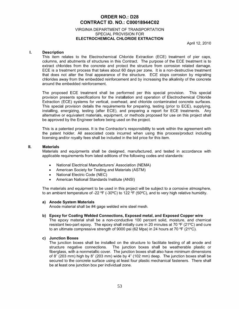
53
54

55
56
57
58
59
60
61
62
63


![Electrochemical Chloride Extraction and Inhibitor Injection in ...life of concrete structures [1, 2], such as buildings and bridges. In addition to freeze/thaw damage, the In addition](https://img.dokumen.tips/doc/110x75/6107411bd600f246c56877a4/electrochemical-chloride-extraction-and-inhibitor-injection-in-life-of-concrete.jpg)


![Efficiency of the Electrochemical methods for the repair of ... ouarti-2018.pdf• Electrochemical chloride extraction [14-17] • Electrochemical realkalisation. [18.19] Electrochemical](https://img.dokumen.tips/doc/110x75/610237547e288528f40cbc06/efficiency-of-the-electrochemical-methods-for-the-repair-of-ouarti-2018pdf.jpg)