Embed Size (px)
Citation preview
19
Use of Composite Wraps to Prevent Acoustically Induced Fatigue Failure in Piping Systems
Emma Purton
Jeremy Leggoe School of Mechanical and Chemical Engineering
Abstract
High pressure drops through relief valves at gas plants can generate sound pressures, which propagate through the downstream pipe, exciting circumferential and dynamic stresses. These stresses can cause acoustically-induced fatigue, leading to failure of the pipe in a matter of hours. This project evaluates the feasibility of retrofitting composite wraps onto at risk pipe sections to reduce the severity of vibration. Damping properties of the composite wrap may reduce the sound pressures in the wall of the pipe, reducing the likelihood of fatigue failure. Using finite element analysis, the reduction in stress and acceleration in the pipe wall is examined, and the wrap lay-up and material properties will be optimized to produce the greatest reduction in sound power level.
1. Introduction The aim of this project is to determine the feasibility of composite wraps as a remedial technology to reduce the potential for failure from acoustically induced fatigue in piping systems. Gas plants have pressure let down systems such as relief valves to reduce the pressure of the processing stream. These high pressure drops generate sound power which propagates through the pipe, exciting circumferential vibration and dynamic stresses. If these stresses exceed a maximum value, fatigue failure can result, causing the pipe to burst or rupture (CSTI Acoustics, 2006). Failure by acoustic fatigue occurs rapidly, often within a few hours (Zamejc 2005). The health, safety, environmental and financial implication of the failure of a pipe carrying hydrocarbons is very significant and there is currently no solution aside from pipe redesign and replacement, both of which are costly. This project will allow the oil and gas industry a greater insight into the mechanisms behind acoustically induced fatigue failure, allowing for more accurate analysis of failures in the future. The implementation of wraps, if considered viable through this project, will help the oil and gas industry prevent such failures in the future, without the need for plant shutdown and costly part replacement 1.1 Literature Review Composites wraps are currently used to repair corrosion damaged pipes and increase the pressure containment capabilities of pipework and pressure vessels (Toutanji 2008). There have been several research projects focusing on the use of composite wraps as a means of repair for corrosion damaged pipes but there has been little research into what impact the application of composites have on the mechanical properties of the protected pipe, or how the properties of the composite effect the interactions between the materials. There has been extensive research into the development of mathematical and geometric models to predict the
CEED Seminar Proceedings 2012 Purton: Use of Composite Wraps to Prevent Fatigue Failure - FEA
20
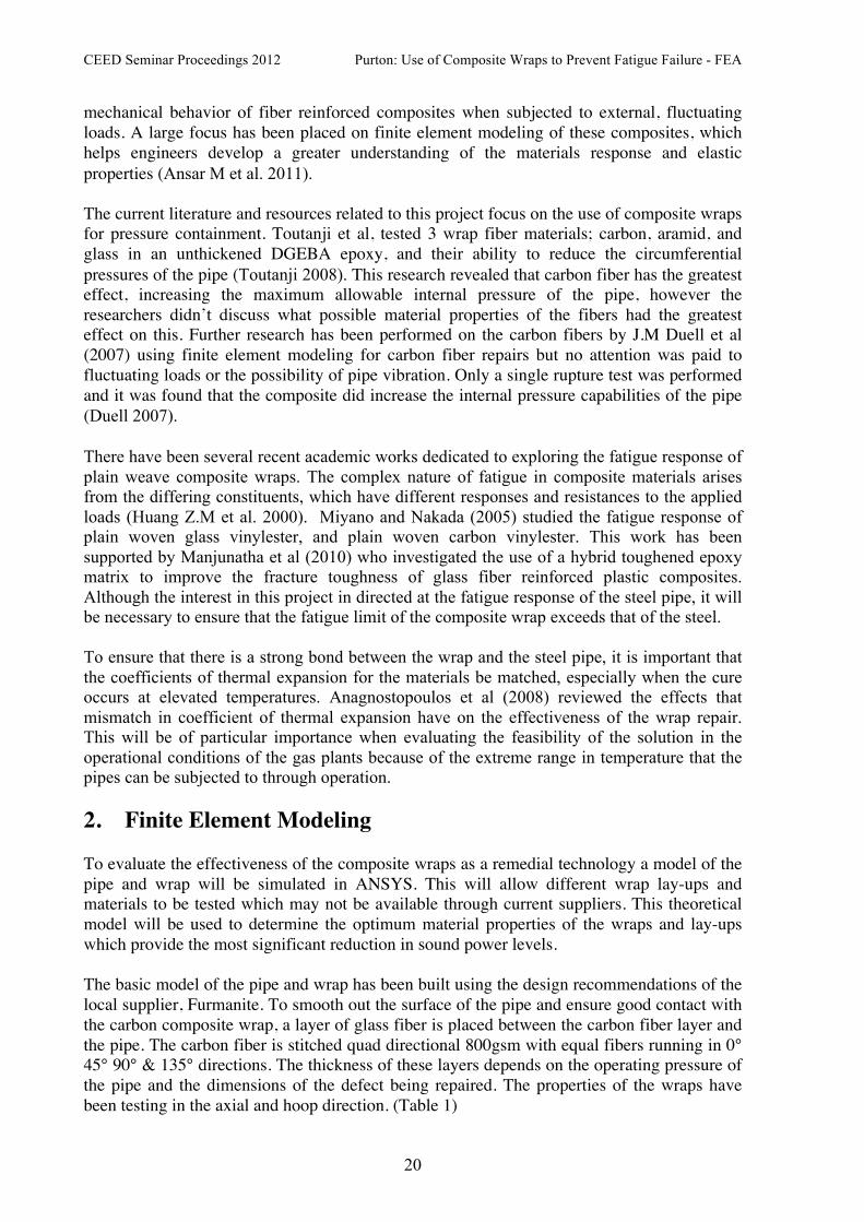
mechanical behavior of fiber reinforced composites when subjected to external, fluctuating loads. A large focus has been placed on finite element modeling of these composites, which helps engineers develop a greater understanding of the materials response and elastic properties (Ansar M et al. 2011). The current literature and resources related to this project focus on the use of composite wraps for pressure containment. Toutanji et al, tested 3 wrap fiber materials; carbon, aramid, and glass in an unthickened DGEBA epoxy, and their ability to reduce the circumferential pressures of the pipe (Toutanji 2008). This research revealed that carbon fiber has the greatest effect, increasing the maximum allowable internal pressure of the pipe, however the researchers didn’t discuss what possible material properties of the fibers had the greatest effect on this. Further research has been performed on the carbon fibers by J.M Duell et al (2007) using finite element modeling for carbon fiber repairs but no attention was paid to fluctuating loads or the possibility of pipe vibration. Only a single rupture test was performed and it was found that the composite did increase the internal pressure capabilities of the pipe (Duell 2007). There have been several recent academic works dedicated to exploring the fatigue response of plain weave composite wraps. The complex nature of fatigue in composite materials arises from the differing constituents, which have different responses and resistances to the applied loads (Huang Z.M et al. 2000). Miyano and Nakada (2005) studied the fatigue response of plain woven glass vinylester, and plain woven carbon vinylester. This work has been supported by Manjunatha et al (2010) who investigated the use of a hybrid toughened epoxy matrix to improve the fracture toughness of glass fiber reinforced plastic composites. Although the interest in this project in directed at the fatigue response of the steel pipe, it will be necessary to ensure that the fatigue limit of the composite wrap exceeds that of the steel. To ensure that there is a strong bond between the wrap and the steel pipe, it is important that the coefficients of thermal expansion for the materials be matched, especially when the cure occurs at elevated temperatures. Anagnostopoulos et al (2008) reviewed the effects that mismatch in coefficient of thermal expansion have on the effectiveness of the wrap repair. This will be of particular importance when evaluating the feasibility of the solution in the operational conditions of the gas plants because of the extreme range in temperature that the pipes can be subjected to through operation. 2. Finite Element Modeling To evaluate the effectiveness of the composite wraps as a remedial technology a model of the pipe and wrap will be simulated in ANSYS. This will allow different wrap lay-ups and materials to be tested which may not be available through current suppliers. This theoretical model will be used to determine the optimum material properties of the wraps and lay-ups which provide the most significant reduction in sound power levels. The basic model of the pipe and wrap has been built using the design recommendations of the local supplier, Furmanite. To smooth out the surface of the pipe and ensure good contact with the carbon composite wrap, a layer of glass fiber is placed between the carbon fiber layer and the pipe. The carbon fiber is stitched quad directional 800gsm with equal fibers running in 0° 45° 90° & 135° directions. The thickness of these layers depends on the operating pressure of the pipe and the dimensions of the defect being repaired. The properties of the wraps have been testing in the axial and hoop direction. (Table 1)

CEED Seminar Proceedings 2012 Purton: Use of Composite Wraps to Prevent Fatigue Failure - FEA
21
Steel Pipe Glass Fiber Carbon Fiber Dimensions 60mm OD
2 mm Thickness 3.215m long
0.5mm thick 5.05mm thick
E (hoop)
210 GPa 16GPa 32.5GPa
E (axial) 210GPa 14.8GPa 33.8 GPa ν(axial) 0.303 0.31 0.56 ν(hoop) 0.303 0.28 0.32
Shear Modulus - 432 MPa 432 MPa Table 1 Material Models of the experimental model
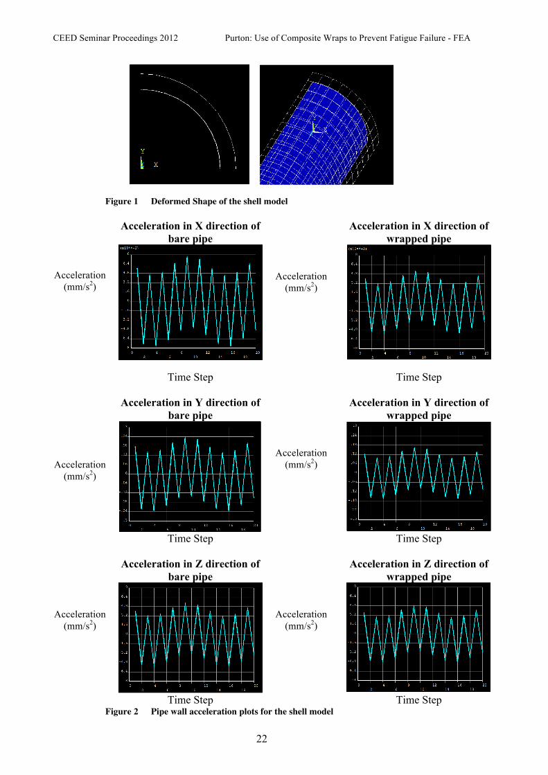
2.1 Shell Element Modeling An initial model has been built in ANSYS using shell elements, which model only a quarter of the pipe to reduce the computational time. Shell elements have been used which are suitable for modeling thin structures. The four node element has 6 degrees of freedom at each node and can be used for layered applications and composite structures. The Shell elements also support rotation of the model, which is important in vibrational analysis. The limitations of this model are its inability to obtain and average nodal solution. This is because shell elements don’t have a consistent coordinate system which leads to incorrectly averaged nodal results. Because of this the stress response of the pipe cannot be plotted, however the modal shapes of the vibrational response can be investigated. It can however provide a good basis for analysis because of the decreased computational time, and can provide information on the acceleration of the pipe walls. The shell elements allow for a layered function without the use of bonding conditions and contact elements between the layers, making it a simple and user friendly approach. 2.2 Solid Element Modelling A three dimensional model will also be developed using solid elements. This will be beneficial when determining mode shapes; however there will be an increase in computational time due to an increased number of nodes per element. The models areas are meshed with a 2 dimension quadratic element and are then extruded with 3 dimensional brick elements. These elements have 3 translational degrees of freedom in the x,y and z directions. 3. Results and Discussion 3.1 Shell Model Analysis The current shell model has been tested using both constant and fluctuating loads, and the mesh has been tested for convergence. A transient load of 100 sin30t (MPa) has been applied. This is a larger load then the one that will be applied to the experimental model and has been chosen as a simplistic characterization of the actual load for the initial analysis. Because a longitudinal wave will be travelling through the pipe, a sin wave can be used to model the fluctuations. By reviewing the deformed shape of the model we can conclude the accuracies of the boundary conditions of this model.
CEED Seminar Proceedings 2012 Purton: Use of Composite Wraps to Prevent Fatigue Failure - FEA
22
Figure 1 Deformed Shape of the shell model
Acceleration in X direction of
bare pipe Acceleration in X direction of
wrapped pipe
Acceleration
(mm/s2)
Acceleration (mm/s2)
Time Step Time Step
Acceleration in Y direction of bare pipe
Acceleration in Y direction of wrapped pipe
Acceleration (mm/s2)
Acceleration (mm/s2)
Time Step
Time Step
Acceleration in Z direction of bare pipe
Acceleration in Z direction of wrapped pipe
Acceleration (mm/s2)
Acceleration (mm/s2)
Time Step Time Step
Figure 2 Pipe wall acceleration plots for the shell model

CEED Seminar Proceedings 2012 Purton: Use of Composite Wraps to Prevent Fatigue Failure - FEA
23
The results returned by the fluctuating analysis shows that the employment of the composite wrap decreases the acceleration in the wall of the pipe. This will decrease the amplification of the oscillations and in turn the sound power level in the pipe. The plots of the acceleration against the time step when a pressure of 100sin (30t) was applied to the inner wall of the pipe are shown below. The results show a decrease in acceleration in the x direction of the pipe of 30.3%. The reduction in the y direction is also 30.3% while in the z direction the acceleration has decreased by 10.61% The stress levels in the pipe wall vary as the thickness of the carbon fiber layer is altered. The Furmanite system consists of carbon layers of 1.01mm thick. The addition of each layer has been tested under the fluctuating load using the shell elements. The percentage reduction between each layer is shown in the table 2 below. Number
of Layers Maximum Stress in
pipes (MPa) Reduction in
Maximum stress Minimum Stress in the pipe
(MPa) 1 35.711 - 34.825 2 27.953 21.7% 27.004 3 22.952 17.8% 22.075 4 19.466 15.1% 18.675 5 16.898 13.19% 16.184 6 14.923 11.6% 14.232 7 13.367 10.4% 12.781 8 12.101 9.47% 11.567
Figure 1 Stresses in the wall of the pipe for a different number of carbon
layers The amount of reduction in the maximum stress for the addition of each layer decreases, meaning that each layer has a less significant impact on stress reduction than the one before. A balance between cost and safety needs to be determined in order to select the optimum number of layers for reduction. 3.2 3D Solid Analyis The solid model analysis is in the very early stages of development. The model is much more complex than the shell model, especially for the three layer model which involves more real constants to account for the bonding effects between the layers. These different layers have been assumed to be perfectly bonded for the initial analysis. Even with this simplification there is a significant amount of computational time and memory needed to complete the analysis, so more refinements will need to be made before the solution can be determined. 5. Conclusions and Future Work The basic Furmanite layup has been tested and which does show a decrease in the stresses in the pipe walls. After the solid model is verified using this lay-up the material properties and wrap layup and thickness will be altered in order to determine the optimum solution for in decreasing the stresses in the pipe. The literature review will provide the basis for identifying
CEED Seminar Proceedings 2012 Purton: Use of Composite Wraps to Prevent Fatigue Failure - FEA
24
the material properties to focus on, and previous research into composite fatigue and elastic properties will help explain the results. 5. References Anagnostopoulos G 7 others (2008) Thermal stress development in fibrous composites. Science direct 62 pp. 341-345 Ansar M & others (2011) Modeling strategies of 3D woven composites: A review. Composite Systems 93 pp. CSTI Acoustics (2006) AIV Basics. Available from: www.cstiacoustics.com Duell J.M & others (2007) Analysis of a carbon composite overwrap pipeline repair system. Sciverse Science Direct 38 pp. 1-9 Huang Z.M & others (2000) Fatigue life prediction of a woven fabric composite subjected to biaxial cyclic loads. Journal of composite materials 60 pp. 479-49 Manjunatha S & others (2010) The Tensile Fatigue behavior of a glass fiber reinforced plastic composite using a hybrid toughened epoxy matrix. Journal of Composite Materials 44 pp 2095- 3011 Miyano Y & others (2005) Accelerated Testing for Long-term Durability of FRP laminates for Marine Use. Journal Of Composite Materials 39 pp. 39-44 Toutanji H & others (DATE) Stress modeling of pipelines strengthened with advanced composites material. Thin Walled structures PAGE Zamejc E, 2005 Acoustic Fatigue – Turbulence Induced Fatigue Failure of Relief System Piping. Available From: http://mycommittees.api.org/standards [26 March 2012]