Embed Size (px)
Citation preview

Software No. 54GB
46730X46730X46730X46730X46730X
SPRAY CONTROL
USE AND MAINTENANCEUSE AND MAINTENANCEUSE AND MAINTENANCEUSE AND MAINTENANCEUSE AND MAINTENANCE

2
ATTENTION!This device is for controlling the ARAG general, section andadjustment valves installed on agricultural machines used forweeding and spraying.Please read the instructions contained in this handbook carefully.ARAG cannot be held liable for damage caused by improper installa-tion or use.
This equipment comes within the limits provided for by EN 50081-1and EN 50082-1 concerning radio-frequency interference.
PRECAUTIONS!In order to safeguard the functionality of the BRAVO30X the followinginstructions must be observed:
- Do not spray water on the equipment.
- Do not use solvent or benzenes to clean the outer parts of thecontainer.
- Observe the foreseen power supply voltage (12 Vdc).
- When arc welding, make sure the BRAVO30X power supply isdisconnected. If necessary, disconnect the leads of the tractorbattery.
- Use only genuine ARAG spare parts and accessories.
The illustrations and technical data contained in this publication refer to thedate of printing. ARAG reserve the right to modify the specifications andinstructions at any time without notice.
For any requests for spare parts or after-sales service, please call yourARAG Dealer or call the ARAG Technical Service on +39 0522 622036.

3
Table of Contents
Table of contents .................................................................................................... 3Introduction ............................................................................................................. 4Composition of Kit .................................................................................................. 4Overall dimensions ................................................................................................ 5Technical and operating particulars ..................................................................... 5Main assembly diagram ......................................................................................... 6Control panel illustration ....................................................................................... 6Description of keys and symbols ........................................................................... 7Control keys ............................................................................................................ 7Adjustment keys ...................................................................................................... 8User programming................................................................................................ 10Introduction .......................................................................................................................... 10Calculating the wheel constant .......................................................................................... 10Wheel constant menu .......................................................................................................... 11Manual setting ................................................................................................................. ..... 11Automatic setting .............................................................................................................. ... 11Variation in the density factory of the product sprayed ................................................... 12Density programming menu ............................................................................................... 12Automatic density calibration ............................................................................................. 12Nozzle delivery rate ........................................................................................................... .. 13Settings preliminary to treatment ....................................................................... 13Field number ........................................................................................................................ 13Resetting the field counters ............................................................................................... 14Setting the amount of liquid placed in the tank ................................................................. 14Filling up by means of the flowmeter ................................................................................... 14Selecting the nozzle ........................................................................................................... . 14Valves with calibrated returns ........................................................................................... 15Setting the calibrated returns ............................................................................................ 16Treatment with automatic control ...................................................................................... 16
Setting the litres/hectare to distribute ............................................................................. 16Setting the distance between rows ................................................................................ 16Starting treatment in automatic ................................................................................... 17
Treatment with manual control .......................................................................................... 17Foam marker .................................................................................................................... ... 17Displaying the counters ...................................................................................................... 18Printing the counters .......................................................................................................... 18Operating errors ................................................................................................... 19Appendix ............................................................................................................... 21Relationship between ISO nozzle type and delivery rate .................................................. 21Troubleshooting .................................................................................................... 22Terms of warranty ................................................................................................. 23
4
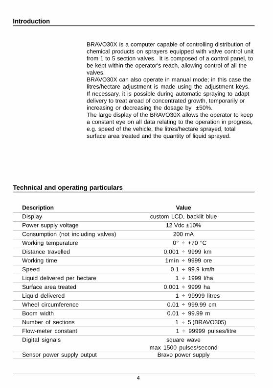
Technical and operating particulars
Description Value
Display custom LCD, backlit blue
Power supply voltage 12 Vdc ±10%
Consumption (not including valves) 200 mA
Working temperature 0° ÷ +70 °C
Distance travelled 0.001 ÷ 9999 km
Working time 1min ÷ 9999 ore
Speed 0.1 ÷ 99.9 km/h
Liquid delivered per hectare 1 ÷ 1999 l/ha
Surface area treated 0.001 ÷ 9999 ha
Liquid delivered 1 ÷ 99999 litres
Wheel circumference 0.01 ÷ 999.99 cm
Boom width 0.01 ÷ 99.99 m
Number of sections 1 ÷ 5 (BRAVO305)
Flow-meter constant 1 ÷ 99999 pulses/litre
Digital signals square wavemax 1500 pulses/second
Sensor power supply output Bravo power supply
Introduction
BRAVO30X is a computer capable of controlling distribution ofchemical products on sprayers equipped with valve control unitfrom 1 to 5 section valves. It is composed of a control panel, tobe kept within the operator's reach, allowing control of all thevalves.BRAVO30X can also operate in manual mode; in this case thelitres/hectare adjustment is made using the adjustment keys.If necessary, it is possible during automatic spraying to adaptdelivery to treat aread of concentrated growth, temporarily orincreasing or decreasing the dosage by ±50%.The large display of the BRAVO30X allows the operator to keepa constant eye on all data relating to the operation in progress,e.g. speed of the vehicle, the litres/hectare sprayed, totalsurface area treated and the quantity of liquid sprayed.

5
Illustration of control panel
A
S
C
BOk Auto
U S ER
Esc
321 4 5
5 GPF4321M
R
T
T
D
Main assembly diagram
A. Control panelB. Starter keyS. Speed sensorC. MagnetsM. Pressure sensor (opt.)F. FlowmeterR. Foam markerD. Loading pumpT. Filling up flowmeter
(or rpm sensor)G. General valveP. Adjustment valve1 - 5 Section valves
fig.1 assembly diagramThe sensor (S) detects the speed of the tractor by means ofthe magnets (C) and at the same time sends the data to theflow-meter (F) and/or pressure trasducer (M) so that thecontrol panel (A) can handle the control unit.
BRAVO30X has a large backlit multifunction display on whichthe user can display all the data defining the treatment inprogress.6 function keys at the side of the display allow the user to viewand set the distribution parameters on the display, togetherwith the other keys on the panel.Below, the function keys are identified by the names F1...F7.
Description of keys and symbols
The following is the list of the functions provided by the keysand the meanings of the symbols shown on the display:

6
Control keys
Distribution value setting
Alternates display of the following data on the display:
Distance travelled
Time worked
Surface area treated
Access to the user programming menu
Alternates display of the following data on the display :
Tank level
Liquid distributed
Battery voltage
Alternates display of the following data on the display :
Flow-rate
Pressure
Rpm
Allows nozzle selection
Activates the left-hand side of the foam marker
Activates the right-hand side of the foam marker
fig.2 BRAVO305 control panel

7
Selects automatic or manual operation
Increase keyIn Manual mode: Increases the quantity for
distributionIn Automatic mode :Increases the quantity for
distribution in steps of 5%
Decrease key
In Manual mode: Decreases the quantity for distributionIn Automatic mode :Decreases the quantity for
distribution in steps of 5%
Opens/Closes main valve
Controls opening/closing of sections
Increase/Decrease of quantity for distribution
Increases the digit of the value for modification
Decreases the digit of the value for modification
Moves on to the next digit
Confirms the value entered
Exits without modification
Adjustment keys
N.B.: For correct operation, if the number of switches on thecontrol panel is different from the number of section valves,connect the cables as shown in the table below:
N Sections Switches to be used Cables to be connected2 2, 4 2, 43 2, 3, 4 2, 3, 44 1, 2, 4, 5 1, 2, 4, 5
8
Switching onTo activate BRAVO30X, position the starter key on "start";BRAVO30X performs a display test, lighting up all the symbols(fig.3). After two seconds it displays the software release(fig. 4) and then switches to the main menu page (fig. 5).
Setting the contrastTo modify the display contrast, press the and keys toincrease or and to decrease.
Fig.3Display test
Fig.4Software release
Treatment data display
Number of active fieldDistribution
speed
Man/Auto Indicator
Nozzle type
Flow-ratePressurerpm
battery voltageliquid in tanktot. liquid distr.
tot. distancetot. timetot. surface area
Fig.5Main menu page

9
User Programming
IntroductionBefore starting treatment, some settings are necessary toinform the BRAVO30X about the characteristics of the vehicleon which it is installed (by means of the wheel constant), thecharacteristics of the liquid distributed (by means of thedensity), the type of flow-meter connected and the type ofnozzle fitted.
Calculating the wheel constant
It may be necessary to change the wheel on which the speedsensor magnets are installed, or the vehicle on which thesensor itself is installed, meaning that the circumference of thewheel changes.
In this case the constant on the BRAVO30X has to be changedto allow it to measure the distance travelled correctly, and thusmake a correct calculation of the quantity of liquid delivered perunit of surface area.
The wheel constant is the distance the vehicle travels for eachpulse received from the speed sensor.
The following is the procedure for calculating the wheelconstant:Measuring the distance travelled in 10 turns of the wheel thespeed sensor is installed on (with the tyres inflated at workingpressure).
This is the formula to calculate the wheel constant:
Space travelled (m) x 10 = —————————————
number of magnetsExample:- space travelled in 10 turns of the wheel = 25.4 m- number of magnets installed = 10
The wheel constant is:
25.4 x 10 = ———————— = 25.4
1

10
Wheel constant menu
To modify the wheel constant, the user programming menumust be accessed by pressing the key until the screenshown on the left (menu 1.0) appears.
Manual settingThe key can be pressed to insert the value calculated for thewheel constant directly: use the modification keys to changeand confirm the new value (the value set on the display is25.40 cm/pulse).
Automatic setting
BRAVO30X is able to calculate the wheel constant automati-cally, on the basis of the number of pulses received from thespeed sensor, when a distance of known length is travelled.To carry out automatic the constant setting correctly, proceedas follows:
1) Prepare the tractor with the tank 50% full(the test can be carried out with just water ).
2) Drive the tractor to the start of the straight track of knownlength and stop.
3) If the length of the track is different from that set, press and use the modify keys to enter the new value.
4) Press the key beside the word AUtO and drive along thetrack.
5) At the end of the track, stop the tractor and press the key:BRAVO30X calculates the wheel constant automatically andshows it on the display.
N.B.: The test should be carried out on ground of mediumhardness. If distribution is on very soft or very hard ground, thedifference in wheel diameter may lead to a difference in thewheel speed reading, with a consequent error in calculation ofthe distribution.In this case, the wheel constant setting procedure should berepeated.
Fig.6Wheel constant display
Fig.7Automatic setting of wheelconstant

11
Variation of the density factor of the product delivered
When distributing products other than water (e.g. liquid fertilis-ers) the values read by means of the blade or turbine flow-meter may be inaccurate, causing errors on distribution. Toovercome this problem, it is possible to modify a density factorwhich acts as multiplier on the values read by the flow-meter.
N.B.: The ARAG ORION model flow-meter is unaffected by thisproblem.
Density factor programming menuThis menu is accessed from the main display screen bypressing the key for one second.Use the keys to locate on menu 3.0 shown on the left.To modify the value of the density factor, press and use themodification keys (in the example, the factor is 1.00 ).Press to confirm the value and exit or to exit withoutmodifying.
Automatic density calibrationThe automatic density calibration procedure is carried out asfollows:
1) Fill the tank with a known quantity of water2) Reset the field data (page 14)3) Distribute the product (page 16)4) Calculate the amount of liquid distributed5) Press to access the programming mode6) Select menu 3.07) Perform the calibration
Calibration is started by pressing the key beside the wordGAL (fig.8).The screen shows the amount of liquid counted by the compu-ter (in the example 2546 litres) during the last distribution, withthe density value currently memorised.Press the key beside the word rEAL, and enter the quantityof liquid actually delivered during the treatment: the computerwill calculate and memorise the new density factor.
Fig.9Automatic density calibration
Fig.8Density factor programmingmenu

12
Fig.10Modifying the nozzle data
Nozzle Flow-RateIf the computer is not connected to a pressure transducer, itmay still be able to calculate and display the pressure on thebasis of the flow-rate value measured by the flow-meter andthe nozzle flow-rate data.N.B. For correct pressure measurement, the nozzles must bein good condition, so that the real flow-rate is the same as therated flow-rate.If the operator is using nozzles which do not correspond to theISO standard, he can modify the default settings of the elevenpreset ISO nozzles.This menu is accessed from the main menu screen bypressing the key for one second.Use the keys to locate on menu 4.0 (fig.10).As can be seen, nozzle number 5 (red colour ISO 11004) is setto deliver 0.8 litres/minute at a pressure of 3.0 bar. The opera-tor can press the and keys to modify the flow-rate andpressure value as appropriate to the nozzle in use.To restore the ISO value, simply press the key and confirmthe values with the key.See appendix for table 1, showing the relationship betweenpressure and flow-rate for ISO nozzles.
Number of Nozzles(467302 and 467304 versions only for 2- 4-way orchardsprayers)If the computer is installed on an orchard sprayer it is possibleto specify, according to requirements, the number of nozzlesused on each spray boom. By doing this the calculation ofpressure is more accurate if there is no pressure transduceror the regulation is more stable if it is done referring to the dataread by the transducer.You can access this menu from the main menu, press the key for one second.With keys go to menu 5.0 (fig.11).Press the key and the keys to select the sprayboom for which you want to set the number of nozzles.Press key to access data modification and set the numberof nozzles wanted by pressing keys .Press to confirm the data and exit or to exit withoutchanging the data.
N
2 4 5 6 7 8 9 1 0 11 1 21 33
M an
M enu
15.0
NO.n N 4
Fig.11Modifying the nozzle data

13
Fig.13:Setting the tank filling level
Before each treatment, the following operations should becarried out:
1) Set the field number2) Reset the field counters3) Set the amount of liquid put in the tank4) Select the nozzle to be used.5) Set the distribution value.
Field numberBRAVO30X automatically records of the space travelled, timeworked, surface area treated and liquid distributed data.BRAVO30X offers the possibility of nineteen partial counterunits (known for the sake of simplicity as fields), to which thetreatment counts can be addressed.
N.B.: Field number 0 contains the device's absolute counterand cannot be deleted.
To set the field number, keep the field pressed until thescreen shown on the left appears.The keys can be pressed to select the number of thefield; pressing confirms the number selected.Pressing aborts the selection made and returns to themain menu screen.
Resetting the field countersThe key can be pressed to reset the display of one or moreof the counters relating to the field currently selected; the countselected and the symbol flash: pressing confirms thereset, or pressing exits from the deletion mode.N.B.: the counts relative to the symbols which are lit up arereset (in the example in fig. 12, the space travelled, timeworked, surface area treated and liquid distributed counts arereset). To change count, press .
Setting the amount of liquid placed in the tankBRAVO30X is able to calculate the amount of liquid left in thetank starting from the filling value and subtracting the liquiddistributed from it. The computer also warns when the liquidlevel reaches the low threshold by sounding a beeper and byflashing the tank level indicator light .
The amount of liquid placed in the tank is programmed bypressing until the screen on the left is displayed.
Fig.12Resetting the counters
Settings preliminary to treatment

14
Fig.14:Setting the tank filling level
Fig.15: ISO11002 nozzle selection
Pressing the keys sets the tank level at the maximum fillinglevel envisaged by the manufacturer.To set a level different from the maximum filling value, press so that the liquid in tank value flashes and use the modificationkeys to change it.
Filling the tank by means of the flowmeterSo the computer stores the exact quantity of liquid put into thetank, it is possible to fill the tank up with the specific flowmeter.
To do this, access the filling up menu by pressing the keyon the main screen page until the screen page shown in Fig.13 appears.Now fill the tank up by starting the loading pump.The computer shows in real time the quantity of liquid that hasbeen put inside the tank which is added to the liquid that isalready inside it, until the loading pump stops. (In the examplegiven in Fig. 13 there are 2,588 litres inside the tank).Once filling up is finished, return to the main screen page bypressing key .
Selecting the nozzleThe user will have selected the nozzle to be used for thetreatment on the basis of the speed at which the treatment is tobe performed and the quantity of liquid per hectare to be used.This information is fundamental if using a pressure transducerto regulate the distribution, but with a flow-meter alone, it isonly used to correct display of the pressure value calculated bythe computer (it does not affect the distribution setting).Nozzle setting is begun by pressing the function key for onesecond, until the screen shown in fig14 appears.A flashing symbol appears in the bottom of the screen,indicating the type of nozzle selected (in the example, number5).
The flashing symbol is underneath coloured indicators repre-senting the standard ISO nozzle colours.If the nozzle chosen is ISO, e.g. ISO11002 (yellow), simplybring the flashing symbol above the rectangle of the samecolour (yellow) with the keys.Press to confirm the new nozzle and exit or to abort.

15
Fig.18:Setting the calibrated returns
If the operator wishes to use a non-ISO nozzle but still be ableto select the ISO nozzles directly, he can access a nozzleknown as "USER" in which he can set the data of the nozzle inuse.To do this, display the nozzle selection screen as describedearlier and bring the flashing nozzle symbol into the posi-tion (fig.16); the display will contain the indication of thenumber of litres per minute delivered by the nozzle at a givenpressure (in the example, the nozzle delivers 0.70 l/min at apressure of 5.0 bar).
The number in the top left-hand corner indicates the distribu-tion value (in litres/hectare) which the computer will maintainwith the nozzle selected. To change the last value set, simplypress the key and use the modification key.
N.B.: for each nozzle, BRAVO30X always sets the last distribu-tion value used with that nozzle.
Valves with calibrated returnsIf the unit is fitted with valves complete with calibrated return,and if BRAVO30X has been programmed for operation withcalibrated return during installation of the system, at eachnozzle change the flashing message rEG appears on the rightof the display.This reminds the user that he has to perform a new procedureto adjust the calibrated returns.
N.B.: The calibrated return adjustment procedure is necessaryto allow the computer to adjust and display the distributioncorrectly when one or more section bars are closed.
Setting the calibrated returnsSetting of the calibrated returns is started by keeping the function key pressed for 1 second (fig.18).Open all the section valves and the master valve; the flow-ratevalue currently read by the flow-meter (10.0 in the example) isdisplayed beside .Close the first section valve: the flow-rate information beforethe closure is frozen on the display, while the flow-rate valuecurrently read by the flow-meter (with the section valve dis-charging on the calibrated return), given by the sum of the flow-rates to the boom and the tank, by means of the calibrated
Fig.17: Requesting calibrationof the calibrated returns
Fig.16:"USER" nozzle

16
Starting the treatment
Fig.19:Adjusting section n.1
Treatment controlled in automatic mode
Setting the litres/hectare to distributePrior to each distribution you first have to make sure that thedistribution set is correct: press until the value to distributeflashes (Fig.20) and use the modification keys to change andconfirm the value.
Setting the distance between rows(467302 and 467304 versions only for the 2- and 4-wayorchard sprayers)In the case of the orchard sprayer versions 467302 and467304 you will also have to set the distance between therows so that the computer can then make the correctadjustments. By pressing the key followed by themodification keys, you can select one out of the nine storabledistance values.If necessary, it is possible to access modification of one ofthese values by pressing the key and setting another valueby pressing keys and .Press to confirm the data and exit or press to exitwithout changing the data.
return is shown beside .(In the example if fig. 19, this is 8.8).At this point the calibrated return has to be adjusted so that thetwo values are the same: when they coincide the section valvecan be reopened and the operation can be repeated for all theother section valves.Adjustment of the calibrated return is assisted by a beeper andindicator lights; as the calibrated return approaches theoptimal setting, the intermittent sound emitted by the beeperbecomes quicker and quicker, until it becomes continuous(setting OK). During the adjustment three flashing segmentsindicate whether the flow-rate generated by the calibratedreturn is too high or too low (in the example, it is too low).
Caution: the section valves must be closed one at a time: ifmore than one section valve is closed simultaneously, thedisplay shows a dash in the position of the field; otherwise, thenumber of the closed section valve appears.Press to exit from the calibrated return setting procedure.
N
22405.00
P 3
Fig.20:Setting l/ha for distribution
17
Start of treatment in the automatic modeTo perform a treatment in automatic mode, proceed as follows:1) Check that the symbol in the centre of the displayhas illuminated, or press the key so that it appears.2) Open the section valves using the relative keys.3) Go to the beginning of the field for treatment.4) Open the master valve.
During automatic operation, BRAVO30X keeps the litres perhectare applied constant at the value set previously.The control keys can be provided to make a temporary variationin the volume to be distributed (fig.21).The display shows the percentage variation of the volume to bedistributed in alternation with the volume actually applied.To cancel the temporary variation, return the percentagevariation to zero.
Treatment controlled in manual modeTo perform a treatment in manual mode, proceed as follows:1) Check that the symbol has illuminated in the centreof the display or press the so that it appears.2) Open the section valves using the relative keys.3) Go to the beginning of the field for treatment.4) Open the master valve.5) Use the control keys to modify the value of the amount tobe distributed (fig.21).
Attention: in the versions for the 467302 and 467304 orchardsprayers it is also necessary to set the distance between rowsso the computer can display the correct data (page16).
Foam markerIf the foam marker kit is installed, the computer is able tocontrol it in 2 modes:
Manual mode:Press the or keys to activate the side of the foammarker required, and press the same key again to stop it.N.B.: the foam marker is disabled automatically when themaster switch is closed.
Fig.22:Left-hand side foam markeractive .
Fig.21:Controls for varying thedistribution.

18
Displaying the countsOnce the treatment is complete, the operator can consult thedata relating to it.The counts made available by the computer are:
Space travelled (Km)
Time worked (hh.mm)
Surface area treated (hectares)
Liquid distributed (litres)
The counts refer to the number of the field currently selected.When the and keys are pressed, the symbols illustratedabove appear beside the keys in succession.The figure beside the symbol is the value of the count.In the example in fig. 23, for field number 1, the distancetravelled is 253 Km, while the liquid distributed amounts to2588 litres.
N.B.: the distance count only works with the master valveclosed. This count can therefore be used to measure thedistance between the field and the operator's home, or tomeasure the length of a field.
N.B.: the time worked count can be stopped or started bypressing the key.When the count is enabled, the symbol flashes.
Consulting the treatment data
Automatic mode:If the foam marker function has been set for automatic opera-tion, the foam marker stops automatically when the mastervalve is closed and restarts from the opposite side when it isreopened.The active side of the foam marker is indicated by the flashingrow symbol above the boom symbol (fig.22).To stop the foam marker, press the foam marker key or
relating to the active side.After a manual stoppage of the foam marker, next time themaster valve is opened the row symbols above the boomsymbol flash simultaneously to instruct the operator to activatethe side of the foam marker required.
Fig.23Counts

19
Fig.24Printing the treatment data
---- TREATMENT DATA ---------------------------
Area:Consumption:Average distrib.:Distrib. set:Nozzle:Time:Area per hour:
73.0700 ha10040L137.4 L/ha100.0 L/ha33.009 hhhh.mm0.0023
---- GUIDELINE DATA -------------------------------
DistanceTime
2.0330 Km0.15 hhhh.mm
---- OTHER DATA -------------------------------------
Total time 3.32 hhhh.mm
Counters printoutIf the printer (code 467001) or the download software of dataon the personal computer (code 467002) is connected toBRAVO30X, it will be possible to print the data of the fieldcounters.Press keys until the screen page depicted in Fig. 24appears.
Once you have selected the field wanted, press the key tohave the printout of the treatment data.With the counters' printout you can glean the followinginformation:

Nr ERROR MESSAGE CAUSE REMEDY
1 and -
During treatment it is notpossible to distribute thequantity of liquid per unit ofarea set
- Reduce vehicle speed
-Use nozzles capable of higher deliveryrates
- Increase the maximum working pressure
2 and -
During treatment it is notpossible to distribute thequantity of liquid per unit ofarea set
- Increase vehicle speed
-Use nozzles capable of lower deliveryrates
3 and
-In AUTO mode the Bravo 300is not receiving the flow-metersignal
-Check the connection between theflow-meter and the Bravo 300
-
In AUTO mode the mastervalve switch is on ON but thecontrol unit is not receiving anyliquid
- Check that the pump is operating
- Check that there is liquid in the tank
4 and
-In AUTO mode the Bravo 300is not receiving the speedsensor signal
-Check the connection between the speedsensor and the Bravo 300
-In AUTO mode the mastervalve switch is on ON but themachine is not moving
- Put the machine in motion
5 and and
-In AUTO mode the Bravo 300is not receiving the speedsensor and flow-meter signals
-Check the Bravo 300’s connections tothe speed sensor and flow-meter
-In AUTO mode the mastervalve switch is raised but themachine is at a standstill
-Put the machine in motion and start upthe pump
6 -While regulating balancing-valves, Bravo 300 surveys aflow-rate, that is too low
-Check connection between flow-meterand Bravo 300
- Check flow-meter constant's set-up
7 -
While setting wheel constant,Bravo 300 didn't get thecorrect pulses to calculate theconstant
-Repeat wheel constant's automaticset-up
8 -After changing nozzle type,balancing valves must beadjusted
- Adjust balancing valves
9 -Liquid in tank is below reservelevel
- Fill the tank
?
?
?
?
Operating errors
BRAVO30X monitors all distribution parameters constantly.In case of a malfunction, the following error messages appear on thedisplay:
ErO
ErrOr
rEG
?

Troubleshooting
oN TCEFED ESUAC YDEMER
1 atadwohstonseodyalpsidehT - ylppusrewopoN
- tratS"otnoyekretratsehtnruT
- rewopehtnosnoitcennocehtkcehCelbacylppus
- esufniamehtkcehC
2 sevlavehtlortnocotelbissoptonsitI
- detcennoctonerasevlavehT - rotcennocehtputcennoC
- nwolbesuF - esufniamehtkcehC
3 deepsehtwohstonseodyalpsidehT
- gnimmargorpytluaF - ehtkcehC å gnimmargorp
- ehttagnivirratonsilangisehTrosnesdeeps
- deepsehthtiwsnoitcennocehtkcehCrosnes
- stengamneewtebecnatsidehtkcehCrosnesdna
4 esicerpmisideyalpsiddeepsehT - gnimmargorpytluaF
-
-
-
ehtkcehC å gnimmargorp
cehC stengamfo.onehtk
stengamneewtebecnatsidehtkcehC
rosnesdna
5 tnatsnoctaneveelbatsnusiyalpsiDdeeps
- stengamforebmuntneiciffusnI - stengamforebmunehtesaercnI
6 “esicerpmI á yalpsid” - gnimmargorpytluaF
- htgnelmoobehtgnimmargorpehtkcehC
- -wolF"ehtfognimmargorpehtkcehCytisnedehtdna"tnatsnocretem
- ehtkcehC å gnimmargorp
7“ehT â nodeyalpsideulav”
eulavehtottnereffidsiretupmocehtdetaertyllautcaseratcehehtfo
- gnimmargorpytluaF - 3.ontnioprofsA
- deorezneebtonsahretemehT - “ehtoreZ â retem”
8
“ehT ã ehtnodeyalpsideulav”foeulavehtottnereffidsiretupmoc
dereviledyllautcasertil
- gnimmargorpytluaF- -wolF"ehtfognimmargorpehtkcehC
“dna"tnatsnocretem ä”
- deorezneebtonsahretemehT - “ehtoreZ ã retem”

Appendix
Relationship between ISO nozzle type and flow-rate
Table 1 shows the flow-rate value (expressed in litres/minute)measured at the pressure of 3bar, for the ISO nozzles.
Unit of measure
EU EU t USSurface Hectare (Ha) Hectare(Ha) AcreDist. travell. Km Km MileTime Hours Hours HoursCapacity Litres Tons GallonsVoltage Volt Volt VoltPressure bar bar psi
Flow rate Litres/min t/min Gal/minSpeed Km/h Km/h Miles/hDistribution Litres/Ha t/Ha Gal/Acre
Sect.width metres metres feetNozzle dist. metres metres inchesFlow constant pulse/l pulse/t pulse/GalWheel const. metres/puls metres/puls inches/puls.Tank cap. Litres Tons GallonsP.T.O. rpm rpm rpm
Color Code lt/min
Orange ISO110011 0,40
Dark green ISO110015 0,60
Yellow ISO11002 0,80
Blue ISO11003 1,20
Red ISO11004 1,60
Brown ISO11005 2,00
Grey ISO11006 2,40
White ISO11008 3,20
Cambridgeblue
ISO11010 4,00
Light green ISO11015 6,00
Black ISO11020 8,00
1. ARAG guarantee BRAVO30X for a period of 12 months fromthe date of sale to the user customer (the freight bill of thegoods shall bear witness to this).The parts composing the equipment, which at theunquestionable judgment of our Company turn out to bedefective due to an initial defect in the material ormanufacture, shall be repaired or replaced free of charge atthe closest Service Centre in operation at the time ofrequesting the work. Exceptions to this are the expensesconcerning:- transportation of the equipment to the Service Centre;- dismantling and reassembling of BRAVO30X from the
machine;
2. Warranty does not cover:- transit damage (scratches, dents and the like);- damage due to faulty installation or initial defects from an
insufficient or inadequate electrical system, or alterationsderiving from environmental, climatic, or other conditions;
- damage deriving from using unsuitable liquids;- failures caused by negligence, tampering, user
incapability, or repairs made by non-authorizedpersonnel;
- installation and adjustment;- system references or convenience checks;- maintenance such as cleaning filters, nozzles, etc.;- what may be considered normal deterioration due to use;
3. The equipment shall be restored in the limits of timecompatible with the organizational requirements of theService Centre; the Units or components to be repaired orreplaced shall have to first be washed and cleaned of theresidues of the chemical products used;
4. Repairs made under warranty do not give rise to itsextension or renewal
5. No one is authorized to change the terms and conditions ofwarranty or to issue other statments or writings
6. ARAG shall not be held liable for any damage caused topersons or things by failure or forced suspension of usingthe equipment
7. Parts replaced under warranty remain property of ARAG
8. For any controversy the Court of Reggio Emilia is thecompetent one.
Terms of warranty

42048 RUBIERA (Reggio Emilia) ITALYVia Palladio, 5/ATel. 0522.622011Fax 0522.628944Home page: http://www.aragnet.comE-Mail: [email protected]
D2
00
33
.GB
-m0
3
0
7/2
00
5