Embed Size (px)
Citation preview

USB3.1 Type-C Transmitter and Receiver SolutionsUSBSSP-TX, USB-TX, USB-RMT, BSAUSB31, BSAUSB3, GRL-USB-PD
DPOJET Analysis plots displaying eye mask hits, bath tub curve, and SSC profile
The Tektronix USBSSP-TX and USB-TX Automated Transmitter solutionsprovide an easy way to validate and characterize emerging USB 3.1 Type-C host controllers, hubs and devices with Tektronix MSO/DPO/70000DX/SX series oscilloscopes. The TekExpress USB-RMT software enablesflexible and intuitive receiver margin testing of USB 3.0 designs with theAWG7000 series Arbitrary Waveform Generators. The BERTScopeBSAUSB31 Automated USB 3.1 Receiver Solution is designed to providefast and accurate BERT-based testing with high test throughput, fastmargin testing and a wide range of debugging tools.
BER contour for USB 3.1 Gen 2 at 10Gbps extrapolated at 1E-12
Key features
Transmitter testingProvides a comprehensive automated and manual toolset for USB3.1 Gen1 (5 Gbps) and Gen2 (10 Gbps) verification,characterization, debug, and compliance testSupports Type-C, Standard and Micro connectors for USB3.1 SpecificationProvides automatic processing of USB-IF SIGTEST results withoutmanual interventionDPOJET plugin for USB 3.1 Type-C, Standard and Microconnectors which supports USB3.1 specification and CTS (Gen1 &Gen2) with setup files and MOIAutomatic DUT control and pattern validation to capture allrequired data patterns (CP0, CP1, CP9, CP10, etc.)Automated USB 3.1 Gen1 and Gen2 normative and informativetransmitter tests – single-button execution with no user interactionrequiredSupport embedding all Channels and their respective filter files forType-C, Standard and Micro Connectors using SDLAQuickly validate test status with comprehensive reporting thatdetails test margins, pass/fail results, and plots in PDF, MHT andCSV formats.Manual Lane Switching – Support for reversible Type-C connectorAutomated Physical Layer test support for USB Power Delivery2.0 with packet decode
Receiver testingSupport for a broad range of serial standards, leveraging theBERTScope® and Arbitrary Waveform Generator capabilitiesFully automated receiver compliance and margin testing, includingautomated calibration and integration with a Tektronix powersupply, reducing the test time and complexity of executing receivertestsIndustry leading single-click loopback initiationAccurate and fast BERT-based jitter tolerance testing maximizesreceiver test throughputRobust automation software includes hardware configuration help,report generation, and test databaseFlexible signal impairments covering ISI, SSC and SJ, enablesemulating any length channel/cable combination, any SSC profileat any frequency, and multiple tones simultaneouslyAutomated calibration of signal impairments enables quickcalibration of waveforms, and does not require you to understanddetailed procedures for calibrationProgrammatic interface enables integrating additional testprocedures into the TekExpress® RMT automation framework
www.tek.com 1

Applications
USB transmitter and receiver testing
Host and Device silicon validation
System, peripheral, and hub validation and integration
Manufacturing test
USB Power Delivery (PD) compliance test
Complete automation for USB testingTekExpress USB 3.1 software (USBSSP-TX) provides an automated,simple, and efficient way to test USB 3.1 transmitters consistent with therequirements of the SuperSpeed USB Electrical Compliance TestSpecification (CTS). SuperSpeed USB 3.1 receiver testing is automated onboth the BERTScope (BSAUSB3) and AWG platforms (TEKEXP USB-RMT).
Compliance requirements per the Electrical Compliance Test Specificationfor USB consist of an eye diagram and jitter (Random, Deterministic, andTotal Jitter and SSC Profile) tests. However, the SuperSpeed USB basespecification also includes a set of informative measurements includingtests for Slew, Voltage Levels, and others. The TekExpress USBSSP-TXsoftware is an easy-to-use software package that automates the USB3.1 (5 Gb/s and 10 Gb/s) Normative and Informative transmitter tests.
Schematic for USB TX test setup
Option USBSSP-TX also includes a library of DPOJET setups for USB3.1 (5 Gb/s and 10 Gb/s) Normative and Informative Transmittermeasurements including limits, mask files, and specific reference channelfiles.
While other manufacturers promote standard-specific compliance software,the Tektronix solution provides a comprehensive verification,characterization, debug, and compliance environment. Receiver testing is arequirement for SuperSpeed USB certification. The increase of data ratemakes it critical that the receiver properly interprets the incoming bitstream. The receiver test is a jitter tolerance test that stresses the receiverover defined sinusoidal jitter frequencies and amplitudes as defined in theCTS. All other impairments (RJ, SSC, De-emphasis) remain constant whilethe SJ is swept across the frequencies defined in the standard. Thefollowing table lists the required test frequencies for USB 3.1 SuperSpeedreceiver testing.
Frequency SJ (5 Gb/s) SJ (10 Gb/s)500 kHz 400 ps 476 ps1 MHz 200 ps 203 ps2 MHz 100 ps 87 ps4 MHz N/A 37 ps4.9 MHz 40 ps N/A7.5 MHz N/A 17 ps50 MHz 40 ps 17 ps100 MHz N/A 17 ps
Automated solutions BSAUSB31 for the BERTScope and USB-RMT for theAWG simplify receiver testing. No longer is it a requirement that the enduser be an expert in USB. The process of defining test parameters, puttingthe device into the proper test mode (loopback), measuring errors, showingresults after each frequency is executed, and printing/storing the testresults is fully automated for the user. Both solutions provide all of therequired signal impairments for SuperSpeed USB3, including SJ, RJ, SSC,and De-emphasis.
TekExpress sample report in MHT format
Required test procedures (MOI) can be found at:
Datasheet
2 www.tek.com

www.tek.com/usb
TekExpress automated framework configuration panel
Automated transmitter testing – save timeand resourcesThere is no longer a need to be an expert on transmitter testingprocedures. Remembering the exact steps to take is time consuming andoften requires going back to the Test Specification. USBSSP-TX takes theguesswork out of conducting SuperSpeed USB transmitter testing. Even ifyou remember how to use the test equipment, it is common for even themost experienced operators to forget steps in the procedure or to set up thecorrect parameters, like applying the correct filters or clock recoverytechnique. USBSSP-TX enables engineers to simply select and run thedesired tests, and work on other tasks while the tests are being executed.
SuperSpeed USB 3.1 transmitter testing withUSBSSP-TXSuperSpeed USB transmitters must pass a signal quality test usingSigTest. SigTest is a post-processing electrical test tool available from theUSB-IF (www.usb.org) that measures amplitude, jitter, and mask hits. Inorder to simplify testing, USBSSP-TX automatically configures theoscilloscope, acquires the waveforms, and automates SigTestmeasurements.
A choice is available at run time to process the measurements usingSigTest or, if debug and further analysis is required, with DPOJET.
Compliance testing requires three different test patterns: CP0, CP1, LFPSfor USB 3.1 Gen1 and CP9, CP10, LFPS, SCD1/2, LBPM and PWM forUSB 3.1 Gen2. Controlling the device under test to transmit the requiredtest patterns is simple with USBSSP-TX. State control is fully automated byusing a supported Tektronix Arbitrary Function Generator (AFG) orArbitrary Waveform Generator (AWG). The option is also available tocontrol the DUT using the Auxiliary output of the oscilloscope (though thismethod is not guaranteed for all DUTs). In the event that the DUT is notable to generate the desired test pattern, the user has the flexibility to skipall measurements requiring that pattern without losing any acquired testdata. Once all necessary patterns have been acquired all measurementsare fully automated with USBSSP-TX.
Upon completion of the testing, the application generates a comprehensivereport that lists the measurements, test limits, and margin. The report alsoshows plots representing the eye diagram and SSC profile which are usefulto determine the source of failures or results with minimal margin. In theevent that measurements need to be redone, USBSSP-TX provides anoption to use prerecorded waveforms. This is useful in situations wheredata sharing is required and a DUT is not physically available.
USB 3.1 SuperSpeed (5 Gb/s) transmittertesting with USB-TXUSB 3.1 (5 Gb/s) transmitter measurements (Opt. USB-TX) for the DPO/MSO70000 Series oscilloscopes provides an automated USB3.1 transmitter solution. USB-TX provides a precise verification,characterization, and debug environment built upon the general-purposeanalysis capabilities of DPOJET. USB-TX enables the execution of all USB3.1 Gen1 Normative and Informative transmitter tests. A comprehensiveanalysis environment is provided allowing the user to quickly compare theresults from multiple test configurations. For example, multiple eyediagrams can be displayed at one time allowing the user to analyze theeffects of different clock recovery techniques or software channel models.USB 3.1 Gen1 requires the analysis of the eye diagram with and withoutthe transition bit. With DPOJET the user can easily compare the results ofboth eye diagrams at the same time.
A supported configuration includes a DPO/MSO70000 oscilloscope (orother supported oscilloscope) equipped with DPOJET (Jitter and EyeDiagram Analysis Tools). The software requires a DPO/MSO70000oscilloscope (12.5 GHz or higher required for compliance testing) withDPOJET (Opt. DJA).
USB3.1 Transmitter and Receiver Solutions
www.tek.com 3

USB 3.1 SuperSpeedPlus (10 Gb/s)transmitter testing with Option USB 3.1
USB 3.1 (5 and 10 Gb/s) transmitter measurements for the DPO/MSO70000 Series oscilloscopes provides an automated USB 3.1 5 and10 Gb/s transmitter test solution. USBSSP-TX, like Option USB-TX,leverages the general-purpose analysis capabilities of DPOJET andenables thorough verification and debug of SuperSpeedPlus designs. AsUSB 3.1 requires backward compatibility, Option USBSSP-TX provides thesame measurements for USB 3.1 5 Gb/s as well the 10 Gb/s transmittermeasurements.
New silicon validation is easier with the integrated debug tools offered withDPOJET, SDLA Visualizer, and Option USBSSP-TX. Evaluating designmargin is a critical step while migrating to the 10 Gb/s data rate. Forexample, a shrinking channel loss budget will require more attention thanbefore to the impact of equalization on far end signal quality. Multi-cycleacquisition and regression analysis, and DPOJET visualization tools, canprovide insight into design optimizations. Also with SDLA Visualizer youcan easily compare results with the reference transmitter equalization whilevarying CTLA/DFE parameters to find the best combination to maximizemargins.
Tx (left), Far End (middle), and Post Rx EQ (right) response with SSP measurementsuite
A supported configuration includes a DPO/MSO70000 Series oscilloscope(or other supported oscilloscope) equipped with DPOJET (Jitter and EyeDiagram Analysis Tools) and SDLA Visualizer (SDLA64). The softwarerequires a DPO/MSO70000 Series oscilloscope (greater or equal than16 GHz with DPOJET (Opt. DJA) and SDLA Visualizer (Opt. SDLA64)).
MOI embedded in TekExpress automation framework
USB Power Delivery electrical complianceand decode with GRL-USB-PDGRL-USB-PD power delivery test software for the MSO/DPO5000,DPO7000 and MSO/DPO70000 Series oscilloscopes provide support forthe latest USB PD test specification. Bidirectional communication acrossthe Configuration Channel is transmitted with Biphase Mark Coding (BMC)and this data is compared to a zero and one eye mask at both near and farend. Other supported parametric measurements include rise time andreference bit rate as well as a CC line packet decode for proper datatransmission and detection.
USB Power Delivery electrical test and decode with GRL-USB-PD
Datasheet
4 www.tek.com

Automated receiver testingUSB 3.0 is prevalent in an array of markets ranging from consumerelectronics to computing applications. Often multiple technologies must betested to bring these products to market. The Tektronix USB 3.0 receiverportfolio of the BERTScope and AWG provides broad support for thesestandards. Regardless of the technologies at hand that must be tested withUSB 3.0, Tektronix has a solution. Leading-edge technologies such as PCIExpress 3.0 and SAS-3 that require complex transmitter equalization aresupported with the BERTScope. The unique requirements such as cableemulation for HDMI and pulse width jitter for MIPI are supported with theAWG platform. Both solutions provide an automated test environment forUSB 3.0 receiver compliance and margin testing.
BERTScope automated receiver testingThe BERTScope USB 3.1 Automated receiver test solution is designed tostreamline the often tedious and labor-intensive receiver test workflow. Nolonger is expert USB 3.1 domain knowledge required to configure,calibrate, test, and document the results. Fast and accurate BERT-basedtesting provides high test throughput, intuitive and fast margin testing, andavailability of a wide range of debugging tools when further investigation isrequired. The result is high test productivity starting from setup through tothe documentation of results.
Test configuration wizardThe BERTScope BSAUSB31 Test Configuration Wizard provides step-by-step guidance for receiver test equipment setup and software setup. Clearlydrawn Block diagrams, cabling configurations, and descriptions simplify thetest configuration step.
Test configuration wizard.
Automated stress calibrationAn important step in preparing for receiver testing is the stress sourcescalibration, to make sure that the stress applied at the test fixture to thedevice under test is truly compliant with the test standard. In the past, thesecalibrations were often the most tedious and error-prone steps in thereceiver test setup process. With the BSAUSB31 Automation Software, thecalibration of the stress "recipe" is completely automated, including savingthe calibration data. For test configurations that do not change, this stepneeds to be run only once, and the stored calibration data is immediatelyavailable. Test engineers can now spend less time calibrating, and moretime testing.
Loopback initiationBefore the receiver test can start, the device under test must be put in theproper test mode, called Loopback, where the device is retransmitting theexact same data that was received. Entering Loopback mode is challengingbecause of the variety of loopback negotiation sequences across the rangeof USB 3.1 devices, and compatibility with test equipment characteristics.
The BERTScope BSAUSB31 automation software, operating with theTektronix Instrument Switch (BSASWITCH), provides a robust, hands-offsystem for initiating loopback for both Host and Device-style targets. Inaddition, recovery from loss of synchronization is handled through the useof word-alignment patterns, often avoiding the need to retrain loopback andinterrupt the test process.
Automated loopback initiation.
USB3.1 Transmitter and Receiver Solutions
www.tek.com 5

Jitter tolerance testingJitter Tolerance testing is the essence of the USB 3.0 receiver test, and asingle-click operation is part of the BSAUSB3 software solution. With real-time stress adjustment, quick synchronization, and BER testing capability,the BERTScope provides the ideal platform for fast jitter compliancetesting. Test results are stored using the built-in database for later recalland report generation.
Receiver jitter tolerance margin test.
Receiver test report.
BERTScope jitter decomposition.
Datasheet
6 www.tek.com

Beyond testing compliance, the automation software also provides a single-click solution for finding the ultimate tolerance limits of the device undertest, termed "search for margin".
Remote control protocolTest software can be operated remotely through ASCII commands sentthrough TCP/IP, giving test engineers further flexibility in designing "beyondcompliance" tests.
Debug toolsWhen a device fails to meet the test requirements, the operator has thepower of the full range of BERTScope debugging tools. From intuitive andfast manual stress adjustment to exclusive error analysis capability andjitter decomposition, the BERTScope can help identify subtle issues thatother instruments might miss.
AWG automated receiver testingConfiguring test equipment for receiver testing can often be timeconsuming and cumbersome. The AWG is the only receiver test solution forUSB 3.0 that provides a common test configuration for transmitter andreceiver testing. Where other configurations rely on switches, physical USBcables, and reference channels, the AWG7000 and DPO/MSO70000Series instruments provide a simplified test configuration.
AWG SuperSpeed USB Host setup for transmitter and receiver testing.
Automated calibration in RMTAutomated calibration of signal impairments provides calibration routinesthat are USB3 standard specific, enables quickly calibration of waveformsand does not require you to understand detailed procedures for calibration.The objective of calibration is to compensate the patterns for specific jitterparameters. The typical parameters are de-emphasis, random andsinusoidal jitter, and stressed eye. The procedure sequences through allthe patterns and each pattern is calibrated independently. These values areused for the jitter-controlled generation of patterns and are injected intoDUT during loopback.
The Final Tj check using Calibrated Rj, Sj (50 MHz) and De-emphasis arewithin a range of 85 ps to 100 ps.
The calibration results can be viewed at any time as values and asgraphical plots. Using quadratic fit (also known as curve-fit) for all the targetvalues gives the characteristic curve. The curve fit is useful for estimation ifany of the target values shows nonlinear nature. The respective calibratedvalues are derived from the characteristic curve.
Automated calibration.
USB3.1 Transmitter and Receiver Solutions
www.tek.com 7

Loopback negotiationBefore the receiver test can start, the device under test must be put into theproper test mode, called loopback. In this mode, the DUT is sending theexact same data pattern on its transmit pair as it received. Loopbacknegotiation is one of the most difficult and time-consuming aspects ofperforming receiver testing. The flexibility of the AWG is unparalleled in theability to put devices into loopback. The power is in the real-timesequencing of the AWG that enables the user to create infinite waveformloops, jumps, and conditional branches.
This process is fully automated with the USB-RMT, following the sequencedescribed in the SuperSpeed USB Compliance Test Specification. Fordevices that require a custom loopback method, a custom sequence filecan be created and used with USB-RMT. However, for certification theintent is to require that the device can go into loopback following thesequence described in the CTS.
Error detectionOnce the device is in loopback, an error detection mechanism is required tovalidate that the data pattern being retransmitted from the DUT is what wassent from the AWG. Error detection for USB 3.0 requires the use of an errordetector that works with asynchronous reference clocks. For USB 3.0, theTx and Rx are on separate reference clocks, which requires the use of SKPordered sets to compensate for the frequency delta caused by the separatereference clocks and SSC. A transmitter is required to send SKP orderedsets every 354 symbols, however, the SKP ordered sets may not beinserted in a packet. The result is that the number of transmitted SKPordered sets by the AWG may not match the number of SKP ordered setssent by the DUT. In this event, the error detector must be able to ignoreSKP ordered sets while executing the test.
Realtime oscilloscope error detectError detection for USB 3.0 is supported in the DPO/MSO70000 Series ofreal-time oscilloscopes. USB-RMT automates the interfaces of the errordetector, so no configuration is required. For times when debugging isrequired the error detector includes a user-friendly control interface thatenables the setup and configuration of the error detector.
Testing CP0 compliance pattern with tektronix serial error detector
The process of visually validating that a device is in loopback is simplifiedwith the real-time oscilloscope. For example, in many cases a device maynot be in loopback, but may simply be in the Compliance mode, and this iseasily detected on the real-time oscilloscope. While turning the signalgenerator off the loopback signal should go to an idle state, otherwise thedevice is in a compliance mode.
Error detection with the real-time oscilloscope supports symbol errors,which goes beyond simple character and disparity error detection. Whileoperating in Symbol Error mode, the error detector is looking at 10-bitblocks of data that have been transmitted from the AWG and comparingthose 10 bits to what is received by the error detector. At the same time, acount is maintained which displays how many of those errors werecharacter errors versus disparity errors.
In some cases, the disparity of the SKP ordered set can be reversed whenthe signal is retransmitted. The error detector is smart enough to ignoreSKP ordered sets regardless of the disparity.
The last mode of operation is Bit Error mode. Bit Error mode compareseach bit that is transmitted from the signal generator to the data beingtransmitted to the error detector. While in Bit Error mode, the error detectoris flexible enough to still ignore SKP ordered sets, to properly count thenumber of receiver errors.
Datasheet
8 www.tek.com

Test statusOnce the test is properly configured, USB-RMT will automatically set upand configure the test equipment. As the test points are completed, USB-RMT will update the results dynamically. The results of the tests are shownin a tabular format and a graphical display. The graphical display supportsboth logarithmic and linear scales. Passing results are denoted by a greencircle and failing results are denoted by a red 'X'.
Real-time test status across jitter and frequency ranges
Test reportUpon completion of the test, a comprehensive report is generated in .MHTformat. The results of the test will also be stored in an Excel .XLS file thatcan be used for further data analysis. Included in the test report are theconfiguration settings for the test equipment, the static parameters for thetest (i.e. RJ, Amplitude, SSC Profile, De-emphasis level), a graphicaldisplay of the test results, and a tabular display of the test results.
Test report.
Margin testingWhile the CTS requires a Jitter Tolerance Test and specific frequenciesand amplitudes, it is often necessary to understand at what point thereceiver stops interpreting the incoming data correctly, which determinesthe margin of the device under test. Margin testing is often a long tediousprocess. USB-RMT automates margin testing across a range of SJfrequencies so the user is not required to interface with the software whilethe test is being executed.
The user also has the flexibility to change the SJ amplitude of thecompliance test points. For example, a compliance test can be run with20% margin by easily changing the amplitude of jitter at each frequencyand saving that setup. The setup can be recalled at a later point in time andthe test can be run under tighter conditions.
Jitter tolerance test.
USB3.1 Transmitter and Receiver Solutions
www.tek.com 9

Complex SSC profilesOne source of system failures or PHY noncompliance is SSC. With USB-RMT, the user can quickly modify the SSC deviation and/or frequencymodulation to determine if the SSC is the cause of bit errors.
USB-TX and USBSSP-TX softwareTekExpress Software (with Opt. USB-TX and USBSSP-TX) providesautomation of the Tektronix USB 3.1 transmitter measurements MOI. Asupported configuration includes a DPO/MSO70000 Series oscilloscope (orother supported oscilloscope) equipped with DPOJET (Jitter and EyeDiagram Analysis Tools) and SDLA Visualizer (SDLA64, optional for USB-TX and required for USBSSP-TX).
The following table lists the key differences between the USB-TX and theUSBSSP-TX software solutions.
Key differences between USB-TX and USBSSP-TX
Feature USB-TX USBSSP-TXAutomatic measurementselections based ondevice type, test type, testpoints, and selectedprobes
X X
Automatic selection ofreceiver CTLE filter
CTLE only CTLE/DFE
Automatic selection of Txchannel modeling forsoftware channelemulation
X X
Complete coverage ofUSB 3.1 Normative andInformative tests (see nexttable)
Gen1 (5 Gb/s) Gen1 (5 Gb/s) and Gen2(10 Gb/s)
Automatically save testreports and waveforms
X X
Re-analyze prerecordedwaveforms
X X
Single test report for allmeasurements
Gen1 (5 Gb/s) Gen1 (5 Gb/s) and Gen2(10 Gb/s)
Automated LFPSmeasurements (setup filesonly)
X X
Automated DUT toggle X XAutomated SIGTESTmeasurements
X
Supported USB3.1 transmitter measurements
Specreference
Parameter Symbol(s)
Table 6-17 Unit Interval including SSC UITable 6-15 Table 6-19
Tj – Dual Dirac at 10–12 BER tTX-TJ-DDTx Deterministic Jitter - Dual Dirac tTX-DJ-DDTx Random Jitter - Dual Dirac tTX-RJ-DD
Table 6-16 SSC Modulation Rate tSSC-MOD-RATESSC Deviation tSSC-FREQ-DEVIATION
Table 6-17 Differential p-p Tx Voltage Swing VTX-DIFF-PPLow-power Differential p-p Tx VoltageSwing
VTX-DIFF-PP-LOW
De-emphasized Output Voltage Ratio 1
(5 GT/s)Tx de-emphasis
Maximum Slew Rate (5 GT/s) tCDR_SLEW_MAXSSC df/dt (10 GT/s) SSCdf/dt
Table 6-18 Tx Min Pulse 1 tMIN-PULSE-TJDeterministic Min Pulse 1 tMIN-PULSE-DJTransmitter Eye - Dual Dirac at 10-12
BERtTX-EYE
Transmitter DC Common Mode Voltage 1 VTX-DC-CMTx AC Common Mode Voltage Active 1 VTX-CM-ACPP_ACTIVE
Table 6-20 Preshoot (10 GT/s) PreshootDe-emphasis (10 GT/s) De-emphasis
Table 6-28 LFPS UI Duration tPeriodLFPS Common Mode Voltage VCM-AC-LFPSLFPS Differential Voltage VCM-DFF-PP-LFPSLFPS Rise Time tRiseLFPS Fall Time tFallLFPS Duty Cycle Duty CycleLFPS tPeriod tPeriodLFPS tPeriod-SSP (10 GT/s) tPeriod-SSP
Table 6-29 LFPS tBurst tBurstLFPS tRepeat tRepeat
Table 6-31 LFPS tRepeat-0 (10 GT/s) tRepeat-0 LFPS tRepeat-1 (10 GT/s) tRepeat-1
Table 6-32 LFPS Pulse Width Modulation (10 GT/s) tPWMtLFPS-0 (10 GT/s) tLFPS-0 tLFPS-1 (10 GT/s) tLFPS-1
1 Denotes Informative tests, all other tests are Normative.
Datasheet
10 www.tek.com
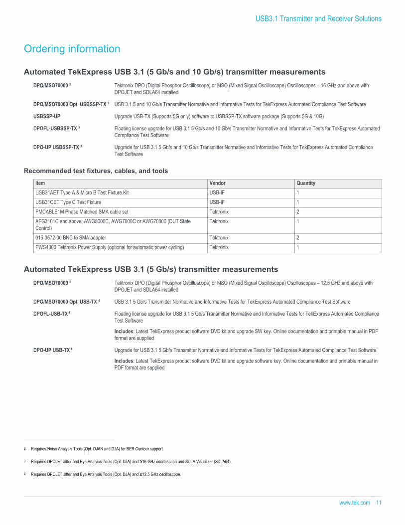
Ordering information
Automated TekExpress USB 3.1 (5 Gb/s and 10 Gb/s) transmitter measurementsDPO/MSO70000 2 Tektronix DPO (Digital Phosphor Oscilloscope) or MSO (Mixed Signal Oscilloscope) Oscilloscopes – 16 GHz and above with
DPOJET and SDLA64 installed
DPO/MSO70000 Opt. USBSSP-TX 3 USB 3.1 5 and 10 Gb/s Transmitter Normative and Informative Tests for TekExpress Automated Compliance Test Software
USBSSP-UP Upgrade USB-TX (Supports 5G only) software to USBSSP-TX software package (Supports 5G & 10G)
DPOFL-USBSSP-TX 3 Floating license upgrade for USB 3.1 5 Gb/s and 10 Gb/s Transmitter Normative and Informative Tests for TekExpress AutomatedCompliance Test Software
DPO-UP USBSSP-TX 3 Upgrade for USB 3.1 5 Gb/s and 10 Gb/s Transmitter Normative and Informative Tests for TekExpress Automated ComplianceTest Software
Recommended test fixtures, cables, and tools
Item Vendor QuantityUSB31AET Type A & Micro B Test Fixture Kit USB-IF 1 USB31CET Type C Test Fixture USB-IF 1 PMCABLE1M Phase Matched SMA cable set Tektronix 2 AFG3101C and above, AWG5000C, AWG7000C or AWG70000 (DUT StateControl)
Tektronix 1
015-0572-00 BNC to SMA adapter Tektronix 2 PWS4000 Tektronix Power Supply (optional for automatic power cycling) Tektronix 1
Automated TekExpress USB 3.1 (5 Gb/s) transmitter measurementsDPO/MSO70000 2 Tektronix DPO (Digital Phosphor Oscilloscope) or MSO (Mixed Signal Oscilloscope) Oscilloscopes – 12.5 GHz and above with
DPOJET and SDLA64 installed
DPO/MSO70000 Opt. USB-TX 4 USB 3.1 5 Gb/s Transmitter Normative and Informative Tests for TekExpress Automated Compliance Test Software
DPOFL-USB-TX 4 Floating license upgrade for USB 3.1 5 Gb/s Transmitter Normative and Informative Tests for TekExpress Automated ComplianceTest Software
Includes: Latest TekExpress product software DVD kit and upgrade SW key. Online documentation and printable manual in PDFformat are supplied
DPO-UP USB-TX 4 Upgrade for USB 3.1 5 Gb/s Transmitter Normative and Informative Tests for TekExpress Automated Compliance Test Software
Includes: Latest TekExpress product software DVD kit and upgrade software key. Online documentation and printable manual inPDF format are supplied
2 Requires Noise Analysis Tools (Opt. DJAN and DJA) for BER Contour support.
3 Requires DPOJET Jitter and Eye Analysis Tools (Opt. DJA) and ≥16 GHz oscilloscope and SDLA Visualizer (SDLA64).
4 Requires DPOJET Jitter and Eye Analysis Tools (Opt. DJA) and ≥12.5 GHz oscilloscope.
USB3.1 Transmitter and Receiver Solutions
www.tek.com 11

Recommended test fixtures, cables, and tools
Item Vendor QuantityUSB31AET Type A & Micro B Test Fixture Kit USB-IF 1 PMCABLE1M Phase Matched SMA cable set Tektronix 2 AFG3101C and above, AWG5000C, AWG7000C or AWG70000 (DUT StateControl)
Tektronix 1
015-0572-00 BNC to SMA adapter Tektronix 2 PWS4000 Tektronix Power Supply (optional for automatic power cycling) Tektronix 1
Automated USB Power Delivery test softwareGRL-USB-PD USB Power Delivery Electrical Compliance and Decode Software. Requires MSO/DPO5000, DPO7000, or MSO/DPO70000
Series oscilloscope
Includes: Latest GRL-USB-PD product software CD kit and upgrade software key. Online documentation and printable PDFformat are supplied.
Automated BERTScope USB 3.1 receiver margin and compliance test (5 & 10 Gb/s)BSAUSB31 Receiver Test Bundle Includes: BSAUSBSOFT – USB 3.1 Automation Software, BSASWITCH – BERTScope Intelligent Switch with driver
Requires: BSA125C or higher BERTScope 5, DPP125C Digital Pre-emphasis Processor, CR125A Clock Recovery
Automated BERTScope USB 3.0 receiver margin and compliance test (5 Gb/s)BSAUSB3 Receiver Test Bundle Includes: BSAUSBSOFT – USB 3.0 Automation Software, BSASWITCH – BERTScope Intelligent Switch with driver
Requires: BSA85C or higher BERTScope 5, DPP125C Digital Pre-emphasis Processor, CR125A Clock Recovery
Automated TekExpress USB 3.0 receiver margin and compliance testDPO/MSO70000 Opt. ERRDT Frame and Bit Error Rate Detector for high-speed serial standards
DPO/MSO70000 Automated TekExpress USB 3.0 Receiver Margin and Compliance Test Software.
Order this option (TEKEXP) and Opt. USB-RMT if TekExpress (TEKEXP) is not already owned. The software installs on thecontroller PC. A USB key dongle with software key enables the selected set
TEKEXP Opt. USB-RMT,TEKEXPUP Opt. USB-RMT
Automated TekExpress USB 3.0 Receiver Margin and Compliance Test Software
Order this option if you already own TekExpress (TEKEXP). The USB key dongle will be upgraded with Opt. USB-RMT
Includes: Latest TekExpress product software DVD kit (P/N 020-2913-xx) and upgrade SW key. Online documentation andprintable manual in PDF format are supplied
5 Note: Symbol Filtering (Opt. SF) must be ordered separately when ordering BSA125C or higher with option STR.
Datasheet
12 www.tek.com

Prerequisite host system software requirementsFor USBSSP-TX and USB-TX DPO/MSO70000 Series oscilloscope with Microsoft Windows 7 or later OS
For USB-RMT, BSAUSB31, andBSAUSB3
Microsoft XP OS with SP2 or later
Microsoft Excel 2002 or above (USB-RMT only)
Microsoft Access (BSAUSB3 only)
Tektronix PWS4000 6 Power Supply with output current ≥1.2 A
USB 3.0 test fixtures and cables 7
TF-USB3-AB-KIT USB 3.0 A/B fixture/cable Kit
Includes: USB 3.0 Type A to Type B short cable, USB 3.0 calibration board, USB 3.0 Type A plug fixture (TF-USB3-A-P), USB3.0 Type A receptacle fixture (TF-USB3-A-R), USB 3.0 Type B receptacle fixture (TF-USB3-B-R)
TF-USB3-A-P USB 3.0 Type A plug fixture
TF-USB3-A-R USB 3.0 Type A receptacle
Includes: USB 3.0 Type A receptacle fixture and USB 3.0 Type A to Type B short cable
TF-USB3-B-R USB 3.0 Type B receptacle
Includes: USB 3.0 Type B receptacle fixture and USB 3.0 Type A to Type B short cable
174-5772-xx USB 3.0 Type A to Type B short cable
Required equipment for USB 3.1 testingFor a complete list of required equipment please go to:
http://www.tek.com/Measurement/applications/serial_data/usb.html
6 Standard copper wire is required to make use of the power supply for DUT power cycle.
7 Tektronix test fixtures are low-loss fixtures designed to minimize the impact of fixturing on measurements and for using software emulation of a hardware channel with the AWG7000 Series. Fixtures used forcertification can be ordered directly from the USB-IF (www.usb.org).
USB3.1 Transmitter and Receiver Solutions
www.tek.com 13

Datasheet
ASEAN / Australasia (65) 6356 3900 Austria 00800 2255 4835* Balkans, Israel, South Africa and other ISE Countries +41 52 675 3777 Belgium 00800 2255 4835* Brazil +55 (11) 3759 7627 Canada 1 800 833 9200 Central East Europe and the Baltics +41 52 675 3777 Central Europe & Greece +41 52 675 3777 Denmark +45 80 88 1401 Finland +41 52 675 3777 France 00800 2255 4835* Germany 00800 2255 4835*Hong Kong 400 820 5835 India 000 800 650 1835 Italy 00800 2255 4835*Japan 81 (3) 6714 3010 Luxembourg +41 52 675 3777 Mexico, Central/South America & Caribbean 52 (55) 56 04 50 90 Middle East, Asia, and North Africa +41 52 675 3777 The Netherlands 00800 2255 4835* Norway 800 16098 People's Republic of China 400 820 5835 Poland +41 52 675 3777 Portugal 80 08 12370 Republic of Korea +822 6917 5084, 822 6917 5080 Russia & CIS +7 (495) 6647564 South Africa +41 52 675 3777 Spain 00800 2255 4835* Sweden 00800 2255 4835* Switzerland 00800 2255 4835*Taiwan 886 (2) 2656 6688 United Kingdom & Ireland 00800 2255 4835* USA 1 800 833 9200
* European toll-free number. If not accessible, call: +41 52 675 3777
For Further Information. Tektronix maintains a comprehensive, constantly expanding collection of application notes, technical briefs and other resources to help engineers working on the cutting edge of technology. Please visit www.tek.com.
Copyright © Tektronix, Inc. All rights reserved. Tektronix products are covered by U.S. and foreign patents, issued and pending. Information in this publication supersedes that in all previously published material. Specification andprice change privileges reserved. TEKTRONIX and TEK are registered trademarks of Tektronix, Inc. All other trade names referenced are the service marks, trademarks, or registered trademarks of their respective companies.
24 Nov 2016 55W-23929-13
www.tek.com