Embed Size (px)
Citation preview

DEPARTMENT OF THE ARMYU.S. Army Corps of Engineers
CECW-ED Washington, DC 20314-1000 ETL 1110-2-256
Technical LetterNo. 1110-2-256 24 June 1981
Engineering and DesignSLIDING STABILITY FOR CONCRETE STRUCTURES
Distribution Restriction Statement
Approved for public release; distribution is unlimited.
-=. —-..—.
DEPARTMENT OF THE ARMYDAEN-CWE-D US Army Corps Of EngineersDAEN-CWE-S Washington, D.C. 20314
Engineer TechnicalLetter No. 1110-2-256
ETL 1110-2-256
24 June 1981
Engineering and DesignSLIDING STABILITY FOR CONCRETE STRUCTURES
1. Purpose: This ETL contains criteria and guidance for assessing thesliding stability of gravity dams and other concrete structures.
2. Applicability. This letter is applicable to all field operatingactivities having civil works design responsibilities.
3. References.
a. ER 1110-2-1806, ItEarthquakeDesign and Analysis for Corps Of EngineersDams.‘f
b“. EM 1110-1-1801, !?GeologicalInvestigation.”
c. EM 1110-2-1803, “Subsurface Investigation-Soils.“
d. EM 1110-2-1902, ~lstabilityof Earth and Rockfill Dams.”
e. EM 1110-2-1906, “Laboratory Soils Testing.”
f. EM 1110-2-1907, “Soil Sampling.”
g. EM 1110-2-2200, llGravityDam DeSign.”
h. EM 1110-2-2501, “Flood Walls.”
i. EM 1110-2-2502, “Retaining Walls.”
d. Rock Testing Handbook, “Standard and Recommended Methods,” 1978.Available from U.S. Army Waterways Experiment Station, P.O. Mx 631,Vicksburg, MS 39180.
k. Henny D.C., l~stabilityof Straight Concrete Gravity Damsl°
Transactions, berican Society of Civil Engineers, Vol, 99, 1934. Availablefrom Publications Sales Office, Civil Engineering-ASCE, 345 East 47th St., NewYork, NY 10017.
1. International Society for Rock Mechanics, Commission onStandardization of Laboratory and Field Tests, ‘tSuggestedMethods forDetermining Shear Strength,’!Document No. 1, February 1974. Available fromPrinting and Publishing Office, National Academy of Sciences, 2101Constitution Avenue, N.W., Washington, DC 20418.

ETL 1110-2-25624 Jun 81
m. Simmons, Marvin D., “Assessment of Geotechnical Factors Affecting theStability of the Martins Fork Dam,” May 1978. Available from U.S. ArmyEngineer District Nashville, P.O. Box 1070, Nashville, TN 37202.
n. Janbu, N., !!slopeStability COmPutatiOns~1?Embankment Dam Engineering
Casagrande Volume, 1973, John Wiley and Sons, 605 Third Ave., New York, NY10016.
0. Morgenstern, N.R. and Price, V.E., “The Analysis of the Stability ofGeneral Slip Surfaces,” Geotechnique, Vol. No. 15, March 1965 Available fromThe Institute of Civil Engineers, Great George St., London, S.W. 1, England..
4. Action. For designand investigation of concrete structures, theassessment of sliding stability on rock and soil foundations should use theprocedures outlined in the following paragraphs. The following guidance onsliding stability analyses has evolved from over two decades of experience inthe design of substructures on foundations with weak sliding resistance.
5. Summary. This ETL prescribes guidance, developed from presentlyacceptable structural and geotechnical principles, in the form of equationsfor evaluating the factor of safety of single and multiple plane failuresurfaces under both static and seismic loading conditions. Basicconsiderations for determining shear strength input parameters for theanalysis are discussed. Minimum required factors of safety are establishedfor both the static and seismic loading conditions. Background describing thedevelopment of the previously used shear-friction and resistance to slidingdesign criteria for evaluating the sliding stability of gravity hydraulicstructures, and the basic reasons for reDlacing the old criteria, are includedin inclosure one. Example problems for single and multiple wedge systems arepresented in inclosure two. An alternate method of analysis is discussed ininclosure three.
6. DesiRn Process.
a. Analysis. An adequate assessment of sliding stability must accountfor the basic structural behavior, the mechanism of transmitting compressiveand shearing loads to the foundation, the reaction of the foundation to suchloads, and the secondary effects of the foundation behavior on the structure.
b. Coordination. A fully coordinated team of geotechnical and structuralengineers and geologists should insure that the result of the sliding analysesis properly integrated into the overall design of the substructure. Some ofthe critical aspects of the design process which require coordination are:
(1) Preliminary estimates of geotechnical data, subsurface conditions andtypes of substructures.
(2) Selection of loading conditions, loading effects, potential failuremechanisms and other related features of the analytical models.
(3) Evaluation of the technical and economic feasibility of alternativesubstructures.
2
ETL 1110-2-25624 Jun 81
(4) Refinement of the preliminary substructure configuration andproportions to reflect consistently the results of detailed geotechnical siteexplorations, laboratory testing and numerical analyses.
(5) Modification to the substructure configuration or features duringconstruction due to unexpected variations in the foundation conditions.
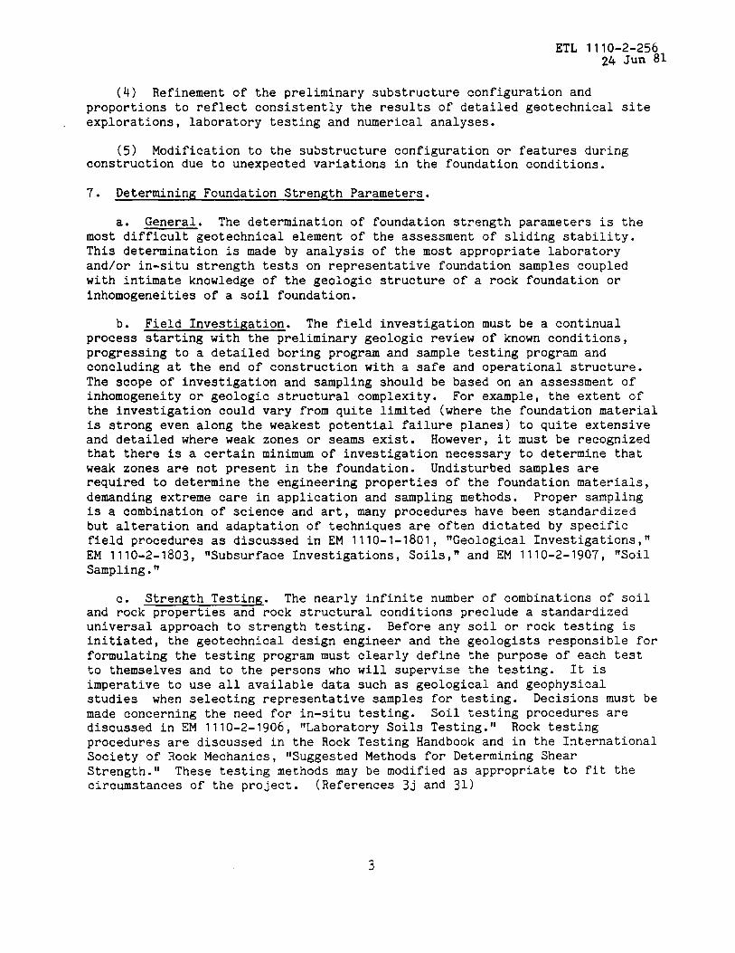
7. Determining Foundation Strength Parameters.
a. General. The determination of foundation strength parameters is themost difficult geotechnical element of the assessment of sliding stability.This determination is made by analysis of the most appropriate laboratoryand/or in-situ strength tests on representative foundation samples coupledwith intimate knowledge of the geologic structure of a rock foundation orinhomogeneities of a soil foundation.
b. Field Investigation. The field investigation must be a continualprocess starting with the preliminary geologic review of known conditions,progressing to a detailed boring program and sample testing program andconcluding at the end of construction with a safe and operational structure.The scope of investigation and sampling should be based on an assessment ofinhomogeneity or geologic structural complexity. For example, the extent ofthe investigation could vary from quite limited (where the foundation materialis strong even along the weakest potential failure planes) to quite extensiveand detailed where weak zones or seams exist. However, it must be recognizedthat there is a certain minimum of investigation necessary to determine thatweak zones are not present in the foundation. Undisturbed samples arerequired to determine the engineering properties of the foundation materials,demanding extreme care in application and sampling methods. Proper samplingis a combination of science and art, many procedures have been standardizedbut alteration and adaptation of techniques are often dictated by specificfield procedures as discussed in EM I11o-I-I8o1, tfGeolOgicalInvestigations!”
EM 1110-2-1803, ‘Subsurface Investigations, Soils,” and EM 1110-2-1907, “SoilSampling.”
c. Strength Testina. The nearly infinite number of combinations of soiland rock properties and rock structural conditions preclude a standardizeduniversal approach to strength testing. Before any soil or rock testing isinitiated, the geotechnical design engineer and the geologists responsible forformulating the testing program must clearly define the purpose of each testto themselves and to the persons who will supervise the testing. It isimperative to use all available data such as geological and geophysicalstudies when selecting representative samples for testing. Decisions must bemade concerning the need for in-situ testing. Soil testing procedures arediscussed in EM I11o-2-19o6, “Laboratory Soils Testing.” Rock testingprocedures are discussed in the Rock Testing Handbook and in the InternationalSociety of Rock Mechanics, !fsuggestedMethods for Determining Shear
Strength.” These testing methods may be modified as appropriate to fit thecircumstances of the project. (References 3j and 31)

d. Desi&n Shear Strengths. Shear strength values used in slidinganalyses are determined from available laboratory and field tests, andjudgment. Information in EM 1110-2-1902 “Stability of Earth and RockfillDams,‘t on types of soils type tests and selection of design shear strengthsshould be used where appropriate. There is no equivalent Engineering Manualwhich provides information on appropriate types of rock tests and selection ofshear strengths. It is important to select the types of tests based upon theprobable mode of failure. Generally, strengths on rock discontinuities wouldb used with an active wedge and beneath the structure. A combination ofstrengths on discontinuities and/or intact rock strengths would be used with apassive wedge.
8. Method of Analysis.
a. Definition of Factor of Safety. The guidance in this ETL is based onmodern principles of structural and geotechnical mechanics which apply asafety factor to the material strength parameters in a manner which places theforces acting on the structure and foundation wedges in sliding equilibrium.The factor of safety (FS) is defined as the ratio of the shear strength (~)and the applied shear stress (T) according to Equations one and two:
(1)
Failure Envelope
b. Basic Concepts and Principles.
(2)
(1) A sliding mode of failure will occur along a presumed failure surfacewhen the applied shearing force (T) exceeds the resisting shearing forces (TF)The failure surface can be any combination of plane and curved surfaces, butfor simplicity, all failure surfaces are assumed to be planes which form the
4
ETL 1110-2-256
24 Jun 81
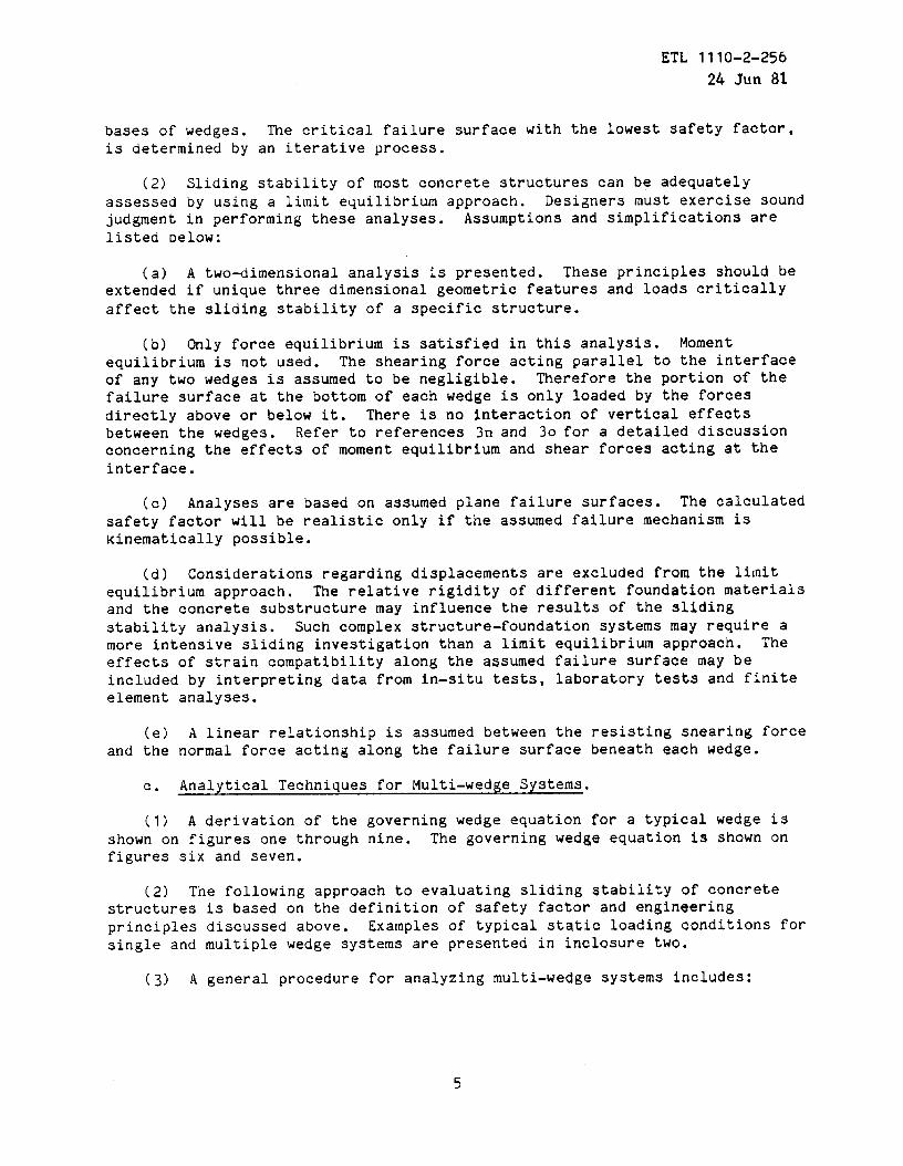
bases of wedges. The critical failure surface with the lowest safety factor,is determined by an iterative process.
(2) Sliding stability of most concrete structures can be adequatelyassessed by using a limit equilibrium approach. Designers must exercise soundjudgment in performing these analyses. Assumptions and simplifications arelisted below:
(a) A two-dimensional analysis is presented. These principles should beextended if unique three dimensional geometric features and loads criticallyaffect the sliding stability of a specific structure.
(b) Only force equilibrium is satisfied in this analysis. Momentequilibrium is not used. The shearing force acting parallel to the interfaceof any two wedges is assumed to be negligible. Therefore the portion of thefailure surface at the bottom of each wedge is only loaded by the forcesdirectly above or below it. There is no interaction of vertical effectsbetween the wedges. Refer to references 3n and 30 for a detailed discussionconcerning the effects of moment equilibrium and shear forces acting at theinterface.
(c) Analyses are based on assumed plane failure surfaces. The calculatedsafety factor will be realistic only if the assumed failure mechanism iscinematically possible.
(d) Considerations regarding displacements are excluded from the lilnitequilibrium approach. The relative rigidity of different foundation materialsand the concrete substructure may influence the results of the slidingstability analysis. Such complex structure-foundation systems may require amore intensive sliding investigation than a limit equilibrium approach. Theeffects of strain compatibility along the assumed failure surface may beincluded by interpreting data from in-situ tests, laboratory tests and finiteelement analyses.
(e) A linear relationship is assumed between the resisting shearing forceand the normal force acting along the failure surface beneath each wedge.
c. Analytical Techniques for Multi-wedge Systems.
(1) A derivation of the governing wedge equation for a typical wedge isshown on figures one through nine. The governing wedge equation is shown onfigures six and seven.
(2) The following approach to evaluating sliding stability Qf concretestructuresprinciplessingle and
(3) A
is based o; the definition of safety factor and engineeringdiscussed above. Examples of typical static loading conditions formultiple wedge systems are presented in inclosure two.
general procedure for analyzing multi-wedge systems includes:
ETL 1110-2-25624 Jun 81
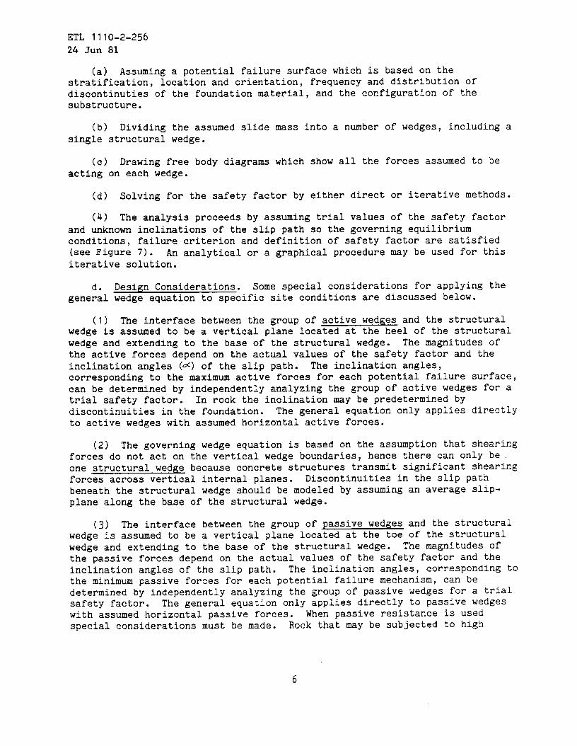
(a) Assuming a potential failure surface which is based on thestratification, location and orientation, frequency and distribution ofdiscontinuties of the foundation material, and the configuration of thesubstructure.
(b) Dividing the assumed slide mass into a number of wedges, including asingle structural wedge.
(c) Drawing free body diagrams which show all the forces assumed to beacting on each wedge.
(d) Solving for the safety factor by either direct or iterative methods.
(4) The analysis proceeds by assuming trial values of the safety factorand unknown inclinations of the slip path so the governing equilibriumconditions, failure criterion and definition of safety factor are satisfied(see Figure 7). An analytical or a graphical procedure may be used for thisiterative solution.
d. Design Considerations. Some special considerations for applying thegeneral wedge equation to specific site conditions are discussed below.
(1) The interface between the group of active wedges and the structuralwedge is assumed to be a vertical plane located at the heel of the structuralwedge and extending to the base of the structural wedge. The magnitudes ofthe active forces depend on the actual values of the safety factor and theinclination angles (~) of the slip path. The inclination angles,corresponding to the maximum active forces for each potential failure surface,can be determined by independently analyzing the group of active wedges for atrial safety factor. In rock the inclination may be predetermined bydiscontinuities in the foundation. The general equation only applies directlyto active wedges with assumed horizontal active forces.
(2) The governing wedge equation is based on the assumption that shearingforces do not act on the vertical wedge boundaries, hence there can only beone structural wedge because concrete structures transmit significant shearingforces across vertical internal planes. Discontinuities in the slip pathbeneath the structural wedge should be modeled by assuming an average slip-plane along the base of the structural wedge.
(3) The interface between the group of ~assive wedges and the structuralwedge is assumed to be a vertical plane located at the toe of the structuralwedge and extending to the base of the structural wedge. The magnitudes ofthe passive forces depend on the actual values of the safety factor and theinclination angles of the slip path. The inclination angles, corresponding tothe minimum passive forces for each potential failure mechanism, can bedetermined by independently analyzing the group of passive wedges for a trialsafety factor. The general equation only applies directly to passive wedgeswith assumed horizontal passive forces. When passive resistance is usedspecial considerations must be made. Rock that may be subjected to high
6

ETL 1110-2-25624 Jun 81
Sliding Stability Analysis ofa General kVedge System
Positive Rotationof Axes
+y
Negative Rotation ‘of Axes
+x
The equations for sliding stability analysis of a general wedge system are based on the right hand
sign convention which is commonly used in engineering mechanics. The origin of the coordinate
system for each wedge is located in the lower left hand corner of the wedge. The x and y axes are
horizontal and vertical respectively. Axes which are tangent (t) and normal (n) to the failure plane
are oriented at an angle (a) with respect to the +x and +y axes. A positive value of ~ is a counter-
clockwise rotation, a negative value of Q is a clockwise rotation.
Figure 1. Sign Convention for Geometry
7

ETL 1110-2-?5624 Sun 81
Sliding Stability Analysis ofa Genera Wl:dge System
~
Top of theith Wedge ‘Yi+l
Top of the(i–lst) Wedge
1+yi
\ /
J
‘Yi–l
t
r’
Figure 2. Geometry of the Typical ith Wedge and Adjacent Wedges

ETL 1110-2-25624 Jun 8i
Sliding Stability Analysis cfa General Wedge System
Top of ihei— 1st WecIge
\
/’:fl,,
/’!II
Vi
I
i\! \\
‘\1,1,1.
/’ i i\I
1111\1’ v \/’: \
t i
P:–1
!
\
Top :)f thei + 1ST}Vedge
/
.
Figure 3. Distributionof Pressuresand ResultantForces Acting on a Typical Wedge
9
ETL 1110-2-25624 Jun 81
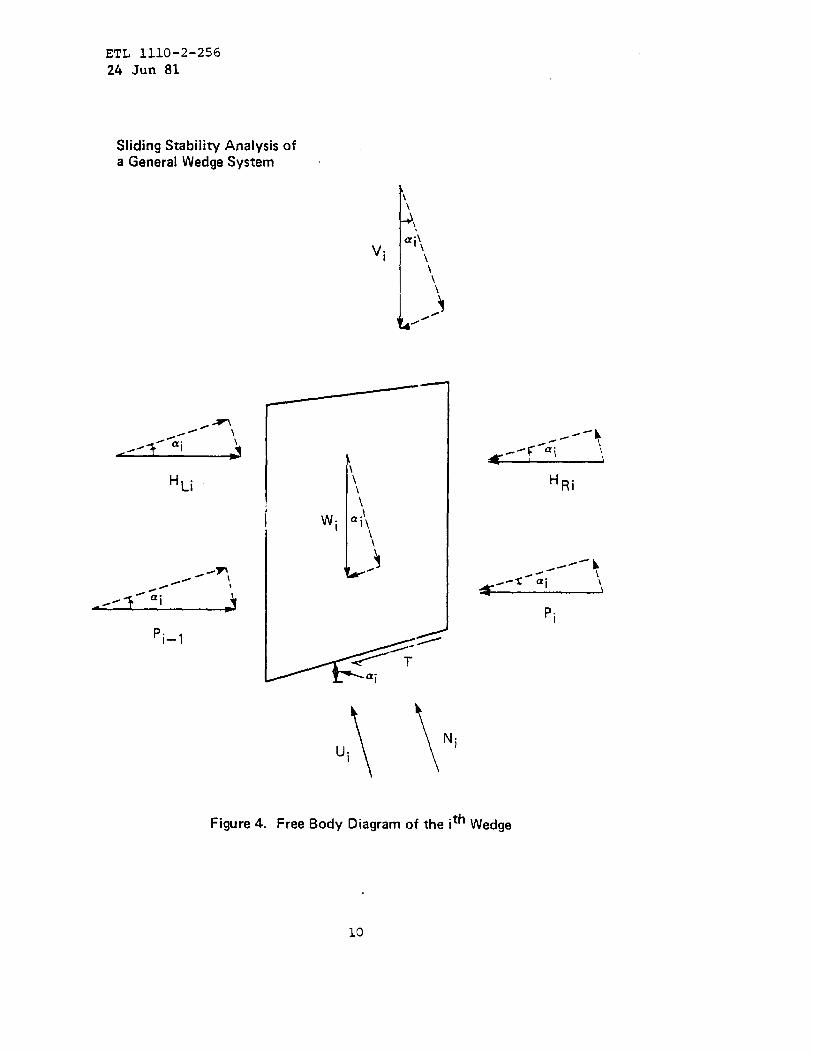
Sliding Stability Analysis ofa General Wedge System
Vi
‘i–l
\
),aii,
\
I \\
4/-
—-----”
I\\\\
Wi a;,
\
J
‘th WedgeFigure 4. Free Body Diagram of the I
10
ETL 1110-2-25624 JurI81
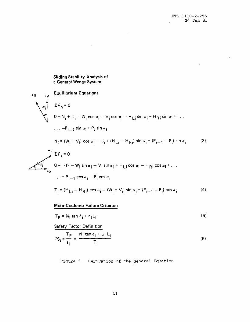
Sliding Stability Analysis ofa General Wedge System
+n +Y Equilibrium Equations
NZFn=O‘i
o= Ni+Ui–wi COsai–vi COSQi– HLi Sin~i+HRisin ai +...
. . . ‘Pi_l sin ai + Pi Sinai
Ni=(wi+ vi) CoSai–ui+(HLi– HRi) Sinai+ (pi_l –pi) Sitlai
+t
LZFt=O
u“1 0 = -Ti ‘Wi Sifl ai – vi Sinai +HLi COSai– HRi CC)s ai ‘.. .
+x
+ Pi_l COSUi. . . – Pi COS ai
Ti = (HLi _ HRi) cos ai – (Wi+ Vi) Sinai+ ipi_l ‘pi) Cosai
Mohr-Coulomb Failure Criterion
TF = Ni tan~i+ ciLi
Safe~ Factor Definition
TF Nitan@i+ci Li
FSi=~ =i Ti
(3)
(4)
(5)
(6)
Figure 5. Derivation of the General Equation
11
ETL 1110-2-25624 Jun 81
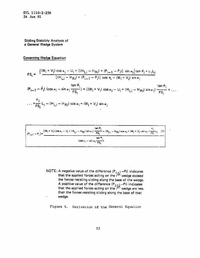
Sliding Stability Analysis ofa General Wedge System
Governing Wedge Equation
{(Wi+ vi) cOS~i - Ui+ [( HLi - HRi) + (pi_l –pi)] Sinai tan@i+ci LiFSi =
}
[(HLi - HRi)+(pi_l ‘pi)] COS ai _ (Wi+ vi) Sinai
tan #i
(pi_,
tan +i- ;i) (COSQi “ ‘—)= [(wi+vi) COSai–ui +( HLi_H~i)sinai]—
- “n a’ FSi FSi ‘“””
‘i—Li–
‘FSi(HLi – HRi) COSai+ (Wi+ vi) Sinai. . .
[(wi+Vi)COS=i -Ui+(HLi - HRi) Sinai]
tan+i Ci
‘- (HLi -H Ri)cosai+(Wi+ Vi) sitlai+~Li
(Pi_, - Pi)= FSi(7) ‘
-f
tan4; ‘–iI [COS. i –Sifl. i+)
i I
NOTE: A negative value of the difference (Pi-l -Pi) indicates
thatthe applied forces acting on the ith wedge exceed
the forces resisting sliding along the base of the wedge.
A positive value of the difference (Pi, -1-Pi) indicates
that the applied forces acting on the ith wedge are less
than the forces resisting sliding along the base of that
wedge.
Figure 6. Derivation of the General Equation
12

ETL 1110-2-25624 Jun 81
Sliding Stability Analysis fora General Wedge System
Solution for the Safety Factor
The governing equation for (Pi_l – pi) applies to the individual wedges
tan@i Ci
i(Wi+Vi)cOsai– Ui+ (HLi – HRi) sinui]— - (HLi -HRi) cosai + (Wi+ Vi) sinai+RLi
(Pi_l -Pi)= FSi I
tan ~;
(COS.i-Sifl u.-)1 FSi
For the sysrern of wedges to act as an integrai failure mechanism, the safery facrors for ail wedges mustbe identical .
FS1=FS2= . ..= FSi_1=FSi=FSi+1 =.. .FSN
N = Number of wedges in the failure mechanism
The acfua/ safety factor ( FS) for sliding equilibrium is determined by satisfying overa// horizonra/ equilibrium
( ~~ H = 0) fOr the errrire SYStem of wedges
Nz (Pi_l -Pi) =0i= 1
And: Po=o PN=O
Usually an irerafjve solution process is used to determine the actual safe~ factor for sliding equilibrium.
Figure 7. Derivation of the General Equation
13
ETL 1110-2-25624 Jun 81
Sliding Stabil iW Anal ysis ofaGeneralWedge System
r.e a \?“,M1
/
/“ ......-~os~ ~ ...... ““...?.,.1
*<! . ....”....~i,ao+i........... ......... ...(’.....””’”’ ““”.. ........””””
e Ui. .. . .
““”.>
““.,>
“..\
““..,\
“., \
““.. \ ...
\
\\
i
,,
\... ‘,I
* i=o$~ i
...‘“”””’..\.....““”””””””””’d
a ‘\~4.\5\oe\4 ‘,5’0
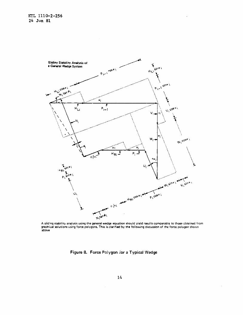
A slid’ng stability analysis using the general wedge equation should yield results comparable to those obtained fromgraphical solutions using force polygons. This is clarified by the following discussion of the force polygon shownabove
Figure 8. Force Polygon ./or a Typical Wedge
ETL 1110-2-25624 Jun 81
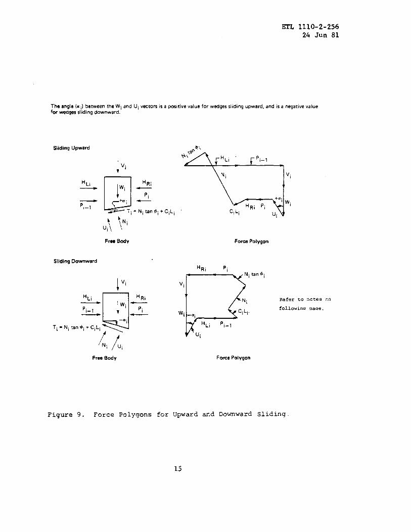
The angle (a i) between the Wi and Ui vector’s is a positive value for wedges sliding upward, and is a negative valuefor wedges sliding downward.
Sliding Upward
1Vi
H ~i
‘u
HRi
!
Wi _
Pi+ai —
~Ti = Ni tan@i+Ci Li
u:\ \Ni
Free Body
Sliding Downward
‘Ni /uiFree Body
HRi
Pi—
~4-\*,X%
v.
CiLiUi
Force Polygon
HRi Pi
Ni tan ~i
Vi
7
b
Ni
Wi _a. CiLi.I
HLi ‘i–l
Ui
Force Polygon
Refer to notes on
followina Pacre.
Figure 9. Force Polygons for Upward and Downward Sliding.
15

ETL 1110-2-25624 Jun 81
NOTES FOR FIGURES 8 and 9
1. The relationships from the typical force polygon are consistent with
the analytical relationships previously developed for the Governing Wedge
Equation.
2. The lines of dimensions on the force polygon
and N1 vectors represent the summation of forces
plane (identical to equation”three).
lyinq parallel to the Ui
normal to the failure
Ni = HLi SiIl al + pi-l SIIl ai + V1 COS al + Wi COS al - Ui - pi sin al - HR1 sin ~j
3. The lines of dimensions on the force polygon shown on Figure Nine lying
parallel to the CiLi and Ni tan $i vectors represent the sumation of forces
parallel to the failure plane (identical to equation four).
Pi-lcosai=vlsin ~+wlsinai+plcos ~+HR1cos ai~i~l+Nitan$l-HLicos ~
4. These two equations can be combined with the safety factor definition
for a typical wedge to obtain the Governing Wedge Equation.
{(Wi+Vi)COS=i-]tanq
ui+(HL1-HR1)sin=l _FSi -(HL1-HR1) cos”i+(wi+vl) sin”i+ & ‘i
i
Pi-l-Pi =
t~$i )(cos=i-sin=iFSi
16

EI’L 1110-2-25615 MC 81
CORRECTED COPY
velocity water scourirq should not be used unless amply protectd. Also, thecompressive stretqth of the rock layers must be sufficient to develop thewedge resistance. M some cases wedge resistance should not be assumedwithout resorti~ to special treatment such as installing rock anchors.
(4) Slidi~ analyses should consider the effects of cracks on the activeside of the structural ~ge in the foundation material due to differentialsettlement, shrinkage or joints in a rock mass. The depth of cracking incohesive foundation material can be estimatd in accordance with equationseight thro~h ten:
2c~dc = — tan (45 +
$~
Y T)
cd = F:
+d = ‘tan-l ( ‘an $ )FS
(8)
(9)
(lo)
The value (dc}in a cohesive foundation cannot exc~ the embedment of thestructural wedge. The depth of cracki~ in massive strory rock foundationsshould be assumed to extend to the base of the structural ~ge. Shearingresistance alo~ the crack should be ignored ati full hydrostatic pressureshould be assumed to act at the bottom of the crack. The hydraulic gradientacross the base of the structural wedge should reflect the presence of a crackat the heel of the structural wedge.
(5) The effects of seepage forces should be included in the slidinganalysis. Analyses should be based on conservative estimates of upliftpressures. Estimates of uplift pressures on the wedges can be ksed on thefollowi~ assumptions:
(a) The uplift pressure acts over the entire area of the base.
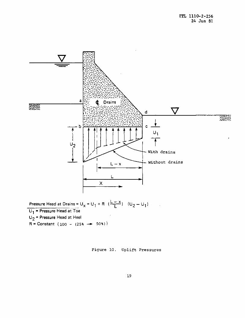
(b) If seepage from headwater to tailwater can occw across a structure,the pressure head at any point should reflect the head loss due to waterflowi~ throqh a medium. The approximate pressure head at any pint can bedetermined by the line-of-seepage method. This method assumes that the headloss is directly proportional to the length of the seepage path. The seepagepath for the structural wedge extends from the upper .sWface (or internalgroundwater level) of the untracked material adjacent to the heel of thestructure, alorq the embedded ~rimeter of the structural @ge, to the uppersurface (or internal groundwter level) adjacent to the toe of the structure.Referri~ to figure ten, the seepage distance is defined by points a~ b? Cl
* and d. The pressure head at any point is equal to the initial total headminus the product of the hydraulic gradient times the seepage path d-distance tothe ~int in question, minus the elevation head. The &ressure head is definedas the height to tiich water rises In a plezometer located at the point underconsideration. The initial total head is the head differential betweenhead~ter and tailwater. The elevation head is the vertical distance betweenthe point bei~below tailwater
considered ad the tallwater elevation (negative ifor positive if above). -timates of pressure heads for the *
17

ETL 1110-2-25624 Jun 81
active and passive wedges should be consistent with those of the heel and toeof the structural wedge. For a more detailed discussion of the line-of-seepage method, refer to EM 1110-2-2501, Floodwalls. For the majority ofstructural “stability computations, the line-of-seepage is consideredsufficiently accurate. However, there may be special situations where theflow net method is required to evaluate seepage problems.
(c) Uplift pressures on the base of the structural wedge can be reducedby foundation drains. The pressure heads beneath the structural wedgedeveloped from the line-of-seepage analysis should be modified to reflect theeffects of the foundation drains. A maximum reduction in pressure head alongthe line of foundation drains equal to the pressure head at the structure toeplus 25-50 percent of the difference between the undrained pressure head atthe toe and that at the line of drains may be assumed. The uplift pressureacross the base of the structural wedge usually varies from the undrainedpressure head at the heel to the assumed reduced pressure head at the line ofdrains to the undrained pressure head at the toe, as shown in figure ten.Uplift forces used for the sliding analyses should be selected in“considerationof conditions which are presented in the applicable designmemoranda. For a more detailed discussion of uplift under gravity dams, referto EM 1110-2-2200, Gravity Dams.
(6) As stated previously, requirements for rotational equilibrium are notdirectly included in the general wedge equation. For some load cases, thevertical component of the resultant applied loads will lie outside the kern ofthe base area, and a portion of the structural wedge will not be in contactwith the foundation material. The sliding analysis should be modified forthese load cases to reflect the following secondary effects due to coupling ofsliding and overturning behavior.
(a) The uplift pressure on the portion of the base which is not incontact with the foundation material should be a uniform value which is equalto the maximum value of the hydraulic pressure across the base, (except forinstantaneous load cases such as due to seismic forces).
(b) The cohesive component of the sliding resistance should only includethe portion of the base area which is in contact with the foundation material.
e. Seismic Sliding Stability.
(1) The sliding stability of a structure for an earthquake-induced basemotion should be checked by assuming the specified horizontal earthquake
18
ETL 1110-2-25624 Jun 81
—b
IU2
1
7HI., II ., ->-,-, .
:\:”\L,\\~-~,$”-’_\/\, -/-:3, ,.-.-. Ii./ ~
~ -
JJ]llL/ With drains
L–x — Without drains
Pressure Head at Drains = Ux =L-x
U, +R (~)
u, = Pressure Head at T;e
U2=Pressure Head at Heel
R = constant {loo - (25% ~ 50%)}
I
(uZ– u,)
.
Figure 10. Uplift Pressures
19
ETL 1110-2T25624 Jun 81
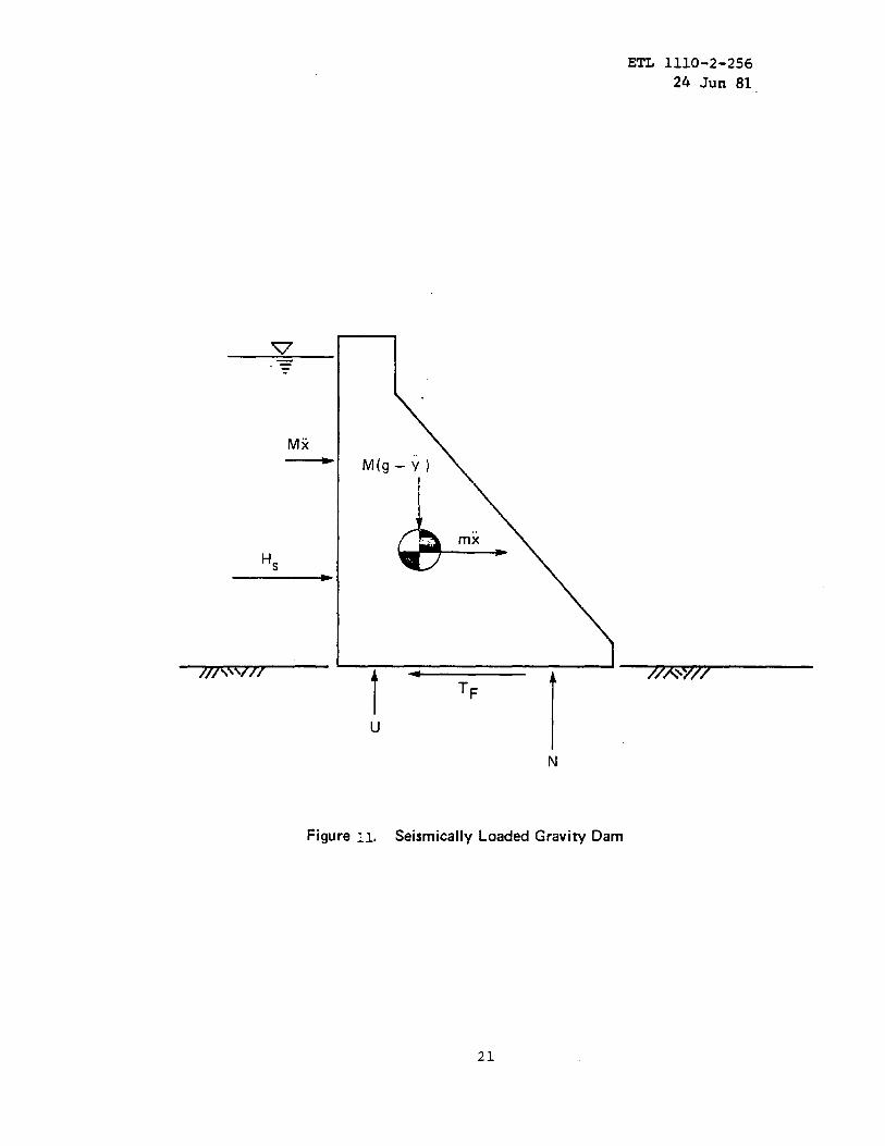
acceleration, and the vertical earthquake acceleration if included in theanalysis, to act in the most unfavorable direction (figure 11). Theearthquake-induced forces on the structure and foundation wedges may then bedetermined by a rigid body analysis.
(2) For the rigid body analysis the horizontal and vertical forces on thestructure and foundation wedges may be determined by using the followingequations: ZH = Mx +& + HS (11)
Iv = Mq - my - U (12)M= mass of structure and-wedges, weight/gm= added mass of reservoir and/or adjacent soil
g = acceleration of gravity..x= horizontal earthquake acceleration4.Y = vertical earthquake accelerationHs = resultant horizontal static forcesu= hydrostatic uplift force
(3) The horizontal earthquake acceleration can be obtained from seismiczone maps (ER 1110-2-1806 “Earthquake Design and Analysis for Corps ofEngineers Dams”) or, in the case where a design earthquake has been specifiedfor the structure, an acceleration developed from analysis of the designearthquake. Guidance is being prepared for the latter type of analysis andwill be issued in the near future; until then, the seismic coefficient methodis the most expedient method to use. The vertical earthquake acceleration isnormally neglected but can be taken as two-thirds of the horizontalacceleration if included in the analysis.
(4) The added mass of the reservoir and soil can be approximated byWestergaardfs parabola (EM 1110-2-2200 ‘rGravityDam Designlt)and the Mononobe-Okabe method (EM 1110-2-2502 “Retaining Wallstt),respectively. The structureshould be designed for a simultaneous increase in force on one side anddecrease on the opposite side of the structure when such can occur.
9. Required Factors of Safety.
a. Factors of Safety. For major concrete structures (dams, lockwalls,basin walls which retain a dam embankment, etc.) the minimum required factorof safety for normal static loading conditions is 2.0. The minimum requiredfactor of safety for seismic loading conditions is 1.3. Flood walls andretaining walls are excepted from the provisions of this paragraph; refer toEM 1110-2-2501 and EM 1110-2-2502 for a discussion of safety factors for thosestructures. Any relaxation of these values will be accomplished only with theapproval of DAEN-CWE and should be justified by comprehensive foundationstudies of such nature as to reduce uncertainties to a minimum.
b. Past Practice. Prior to issuing this ETL, the minimum required factorof safety for static loading conditions (as calculated by the shear frictionmethod) was four. The primary reasons for use of this conservative factor ofsafety were the uncertainty in determining rock shear strength parameters andthe peak shear strengths from tests on intact rock. The minimum requiredfactor of safety for static loading conditions has been reduced to two for thereasons discussed in inclosure one and the following:
20
ETL 1110-2-256
24 Jun 81
N
/// 7//\\
Figure Il. Seismically Loaded Gravity Dam
21

symbol
F
H
L
N
P
FS
T
TF
u
v
w
c
a
LIST OF SYMBOLS
Definition
Forces ,
In general, any horizontal forceapplied above the top or below thebottom of the adjacent wedge.
Length of wedge along the failuresurface.
The resultant normal force along thefailure surface.
The resultant pressure acting on avertical face of a tpical wedae.
The factor-of-safety.
The shearing force actinq along thefailure surface.
The maximum resisting shearing forcewhich can act along the failure surface.
The uplift force exerted along thefailure surface of the wedge.
My vertical force applied above thetop of the wedge.
The total weight of water, soil orconcrete in the wedge.
Cohesion.
The angle between the inclined planeof the ?otential failure surfaceand the horizontal (Fositive counter-clockwise) .
The angle of shearing resistance, orinternal friction.
Weight per unit volume.
22

=
a
T
TF
ETL 1110-2-256
24 Jun 81
LIST OF SYMBOLS
Definition
Normal stress.
Shear stress.
Shear strength.
NOTE : Subscripts containing(i, i-l, if i+lt ‘----1 refer ‘0body forces, surface forces or dimensions associated withthe ith wedge.
Subscripts containing Ri or Li refer to the riuht or leftside of the ith wedge.

ETL 1110-2-25624 Jun gl
(1) Methods of sampling and sample testing have substantially improvedand much better definition of soil and rock mass strengths are now possible.Of the above reasons, the capability of better definition of mass strength is,by far, the most important. Sampling techniques of two or three decades agofavored the collection of intact samples with little attention being given tocore loss zones. Tests were usually performed on intact specimens and gavelarge values for cohesion and angles of internal friction. Testing ofstrengths along discontinuities such as bedding planes, joint planes and testson joint filling materials were rarely performed. Tests were rarely carriedbeyond peak strength to determine ultimate and residual strengths. Currentexploration practice is to emphasize obtaining samples from the weak zones.Tests are run on discontinuities and weak zones. Peak, ultimate and residualstrengths are obtained. If necessary, in-situ tests are performed.
(2) Factors of safety less than four have been used for the design of theWaco, Proctor, Aliceville and Martins Fork projects (projects in SouthwestDivision, South Atlantic Division and.Ohio River Division). Detailsconcerning the design of the Martins Fork Project are available in reference3m.
(3) In past and current stability analyses the three dimensional (side)effects exist, and are not accounted for; which results in additional safety.
c. General. Appropriate values of computed safety factors depend on the;(1) design condition being analyzed; (2) degree of confidence in design shearstrength values; (3) consequence of failure; (4) thoroughness of investigation;(5) nature of structure-foundation interaction; (6) environmental conditionsand quality of workmanship during construction; and (7)judgment based onpast experience with similar structures. For example, for flood controlstructures the most critical loading condition usually is caused by a highreservoir level of infrequent occurrence, and for low-head navigation dams,the most critical loading condition with the greatest head differential is thenormal operating condition, which exists most of the time.
FOR THE COMMANDER:\
3 Incl LLbYD A. DUSCHA, P. E.1. Background Chief, Engineering Division2. EXamples Directorate of Civil Works3. Alternate Method of Analysis
24

ETL 1110-2-256
24 .Jun 81
BACKGROUND
1. Previous Methods. TWO of the approaches to the sliding st~ility
analysis that have been used by the Corps of Engineers (CE), are thesliding resistance and shear-friction methods.
a. Sliding Resistance Method. The sliding resistance method isseldom used by the CE for current designs. This concept was the commoncriterion for evaluating sliding stability of gravity dams fromapproximately 1900 to the mid-1930’s. Experience of the early damdesigners had shown that the shearing resistance of very competentfoundation material need not be investigated if the ratio of horizontalforces to vertical forces (XH/XV)is such that a reasonable safety factoragainst sliding results. The maximum ratio of XflVis set at 0.65 forstatic loadinq conditions and 0.85 for seismic conditions.
b. Shear-Friction.
(1) The shear-friction method of analysis is the guidance currentlyused throughout the CE for evaluating sliding stability of gravity damsand mass concrete hydraulic structures. This method was introduced byHenny in 1933 (Reference 3k “StabilityDams”) . The basic formula is Q = S
F
The shear-friction method was extended
The total resisting shear strength, S,equation:
of Straight Concrete Gravity
in later guidance.
was defined by the
S=sl + k (W-U)
(1)
coulomb
(2)
It is important to note that Henny considered only single, horizontalfailure glanes.
(2) Henny established the minimum shear-friction factor as four (4).Although the rationale for selecting this value is vague, it doesappear to be the approximate average value of Q in Table eight ofReference 3k which compares the dimensions of an ideal dam, uplift forces,
shear-friction safety factors, and nominal slidinq factors.
(3) Records cannot be located to indicate adaptation of Henny’s workinto the Corps of Engineers slidinq stability criteria. ?Jevertheless,
the initial concept of defining the shear-friction factor as the ratio ofthe total resisting shear force acting alonq a horizontal failure planeto the maximum horizontal drivinq force can be attributed to Henny andthus technology of the 1930’s.
Inclosure 11-1
ETL 1110-2-25624 Sun 81
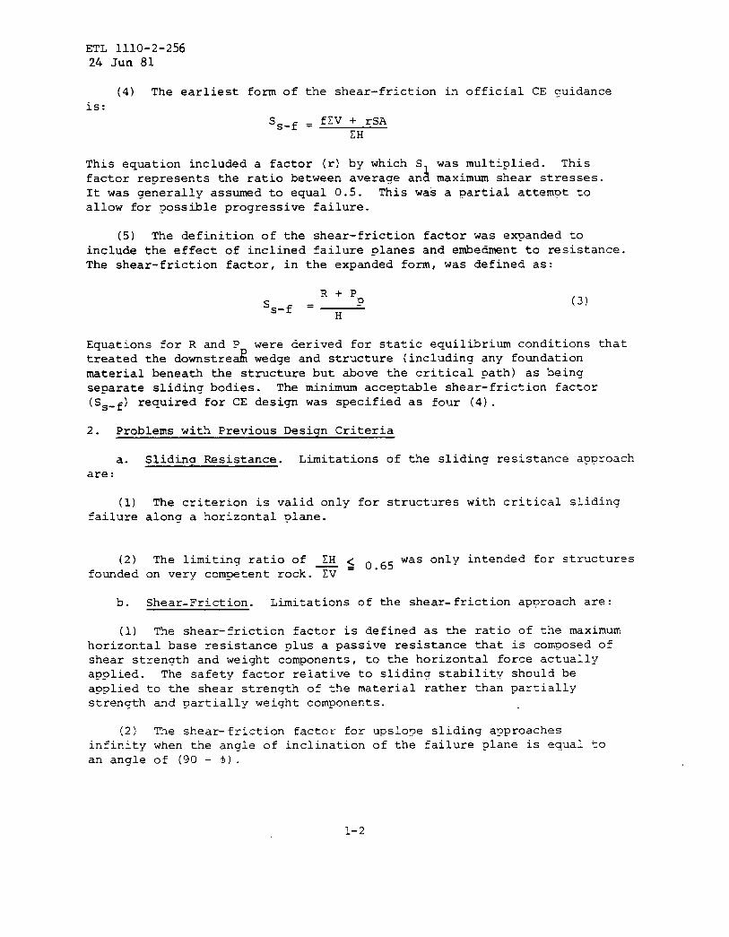
(4) The earliest form of the shear-friction in official CE quidanceis:
ss-f = f~V + rSAZH
This equation included a factor (r) by which S was multiplied. “factor represents the ratio between averaae an~ maximum shear st~~~~s.It was generally assumed to equal 0.5. This was a partial attempt toallow for possible progressive failure.
(5) The definition of the shear-friction factor was e~anded toinclude the effect of inclined failure planes and embedment to resistance.The shear-friction factor, in the expanded form, was defined as:
R+Ps Ps-f = ~
(3)
Equations for R and Ptreated the downstre &
were derived for static equilibrium conditionswedge and structure (including any foundation
material beneath the structure but above the critical path) as beingseparate sliding bodies. The minimum acceptable shear-friction factor
(Ss-f) required for CE design was specified as fol~r(4).
2. Problems with Previous Design Criteria
a.are:
(1)failure
(2)founded
b.
that
Sliding Resistance. Limitations of the sliding resistance approach
The criterion is valid only for structures with critical slidinaalona a horizontal plane.
The limiting ratio of > ~ (),65was only intended for structureson very competent rock. EV
Shear-Friction. Limitations of the shear-friction approach are:
The shear-friction factor is defined as the ratio of the maximum(1)horizontal base resistance plus a passive resistance that is composed ofshear strength and weight components, to the horizontal force actuallyapplied. The safety factor relative to slidina stabilitv should beapplied to the shear strength of the material rather than partiallystrenqth and partially weight components.
(2) The shear-friction factor for upslo~e sliding approachesinfinity when the angle of inclination of the failure plane is equal toan angle of (90 - $) .
1-2
ETL 1110-2-25624 Jun 81
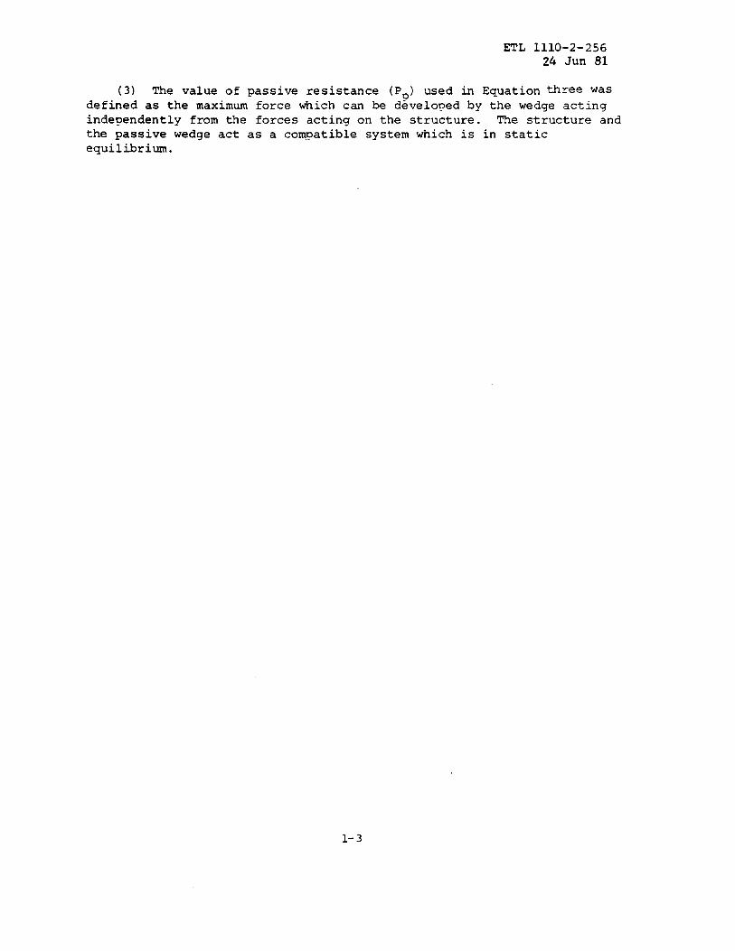
(3) The value of passive resistance (Po) used in Equation three wasdefined as the maximum force which can be developed by the wedge actingindependently from the forces acting on the structure. The structure andthe passive wedge act as a compatible system which is in staticequilibrium.
1-3

ETL 1110-2-256
24 Jun 81
H
k
P
‘P
Q
R
r
s
‘1
ss-f
v
u
w
LIST OF SYMBOLS FOR INCLOSU~ 1
Definition
The portion of the critical potential failuresurface which is in compression.
The summation of horizontal service loads to beapplied to the structure.
The factor of shearing strenqth increase.
The water pressure on the projected area of thestructure assumed to move and actinq on avertical plane normal to the direction of motion.
The passive resistance of the rock wedge at down-stream toe.
Factor of safety of shear.
The maximum horizontal driving force which canbe resisted by the critical path.
The ratio between average and maximum shear stress.
Total resisting shear stren~h acting over thefailure plane.
The total shear strength under conditions of noload.
The shear-friction factor of safety.
The smation of vertical service loads to beapplied to the structure.
The uplift force under the sliding plane.
The weight of the structure above an assumedsliding plane.
1-4

ETL 1110- 2-25624 Jug 81
EXAMPLES
1. Examples of typical static loading conditions for single and multiple
wedge systems are presented in this Inclosure.
2. These examples are provided to clearly demonstrate the procedure for
applying
multiple
the general wedqe equation to the sliding analysis of sinqle and
wedge systems. The variation of uplift pressure, orientation of
failure planes, etc., used in the examples were only selected to simplify
the calculations, and are not intended to represent the only conditions
to be considered during the design of a hydraulic structure.
Inclosure 2
2-1

ETL 1110-2-256
24 Jun 81
81
&lel: Single Wedge
Determine the factor of safety against sliding for the following single wedge system
yw = 62.5
Pk.pcf ~
0.7
100 11
L
7C= 150pcfv=—
100 yw~ L1 = 75’+
In . 4501
‘oo’ww “=’”ksf U, N,
Free Body Diagram
General Wedge Equationtafd +; c,
[(Wi+ Vi) COS~i - Ui+[HLi-HRi)$in ail F:;i——’ -
Pi_, -Pi=(HLi– HRi)COSai+(Wi+ Vi) sins.~&Li
I
tan $ i
(COSUi - sinui —- )FSi
Solva for Safety Factor ( FS)
j=l HR1=O Vl=f) P. P1=O U,= OCOSQ1=l sirlal ‘O
tan $5
O=(W1– U1)— —–HL1+ ‘LlFe FS
1 1HL1 =—(100)2YW = 3f2.5k U1 =—(75) (100) yw= 234.4k t WI = 603.8’1
.f! L
(W1– U1) tan45°+c ,LlFS =
‘Ll
[603.8 - 234.4) (1) + 10 (75) (369.4 + 750)FS = . = 3.5a
312.5 312.5
2-2

ETL 1110-2-256
24 Jun 81
Example 2: Multiple Wedges
Determine the factor of safety against sliding for the following fivewedgesvstetn
\.
11
s
II
2-3

ETL 1110-2-25624 .Jun 81
Sliding Stability AnalysisExample: Five Wedge System
Free Body Diagrams of Wedges
wedgeNo. 1(i= 1}
/ N2
No. 2(i= 2)
WedgeNo. 3
(i =3)
WedgeNo. 4
(i =4)
WedgeNo. 5
(i =5}
2-4

ETL 1110-2-256
24 Jun 81
Slidinq Stability AnalysisExample: Five Wedge System
General Wedge Equation
tan di[( Wi*Vi)cOsa i- Ui+(HLi -H Ri)sinai]_
Ci
Pi_, –P;=–(HL; -H Ri)cosai +( Wi+Vi)sinai+_Li
FSi FSi
I
I
~
#+Ili/,’,.‘,0 ““ .—.——.++x,
—a;
‘\‘.‘~+ti
tan@i
(COSai– Sinai —)FSi
t
‘Yi
F-.*‘ti+Ili .-’.
h,.-’
‘\\
‘,‘.‘\ +a 1
0 — ‘- —- —-*+Xi
Sign Convention for General Equation
Wedge Forces for Trial Safety Factor of 1.5
1=1 HLi=HRi=O
Ian #1 tan 20tan+d=— =— @d = tan-? (0.243) = 13.64°
FSI 1.5
+d
al=-(45°+—)=–51,820
2
I
This orientation of the failure path
sln (-51.82) = –0.786 is only true if thestratification andsurface are horizontal
COS(–51,82) = 0.618
LI = 5/ sin (-51.82)1 = 5/0.786 = 6.36’
2-5

E’TL 1110-2-256
24 Jun 81
Sliding Stability AnalysisExample: Five Wedge System
.
WI= 1(0.117) (5)*6 .36cos (-51.82) = 1.15k J2 1 7.29k $
V, = (25’’.0625) 6.36 COS (–51.82) = 6.14k ~1
1
u,=: (.0625) (25+30) 6.36 = 10.93k?2
tan 20[7.29 (0.618) – 10.931 —+ 7.29 (--0.786)
(P. – P,)= 1.5 = –9.olktan 20
[0.618 – (–0.786)—]1,5
~ HLZ=HRZ=O
tan # z tan 30‘1 (0.385) = 21.05°tan+d=—.c @d = tan
FS2 1.5
@da,=-. (45 +—) = –55.530
2
sin (-55.53) = –0.8244 COS (–55.53) = 0.566
L2 = 10/ Isin (–55.53)1 = 12.13’
1
w~=0.117 (5) (12.13 x0.!j66) +–(.122) (10) (12.13X0.566) = 8.20k$2.
V2 = (25X.0625) (12.13X0.566) = 10.73k 1
1U2=–(0.0625} (30+40) (12.13) = 26.53k7
2
2-6
ETL 1110-2-256
24 Jun 81
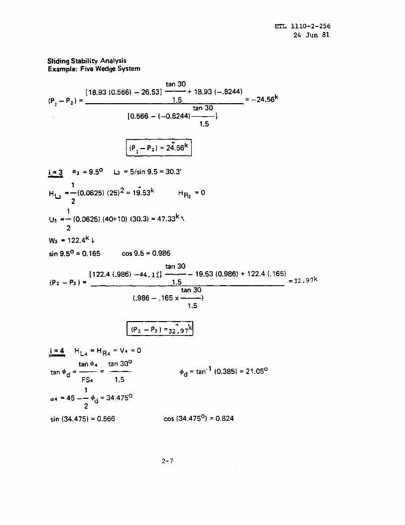
Sliding Stability AnalysisExample: Five Wedge System
tan 30[18.93 (0.566) - 26.53] —+ 18.93(–.8244)
(P, –P2)= 1.5 =- 24.56ktan 30
[0.566 – (-0.8244) 11.5
(Pl - Pz) = 2~.56k
_ “3 =9.5° h =51sin 9.5=30.3’i=3
H~ =1(0.0625) (25)2= l;.53k HR3 =0-L
U3=: (0.0625) (40+10) (30.3) = 47.33k Y
2
W3=122.4k1sin 9.5° = 0.165 COS 9.5 = 0.986
tan 30
[122.4 (.986) -44.1~1 —- 19.53 (0.986) + 122.4 (.165)
(p2-p3)= 1.5 =j2.97k
tan 30(.986 – .165 X—)
1.5
(P2 - P3)‘3z:97k
tan ~4 tan 30°‘1 (0.385) = 21.05°tan @d =— =— $d = tan
FS4 1.5
1
.4 “ 45 –– +~ = 34.475°2
sin (34.475) = 0.566 COS(34.475°) = 0.824
2-7
ETL 1110-2-256
24 Jun 81
Sliding Stability AnalysisExample: Five Wedge System
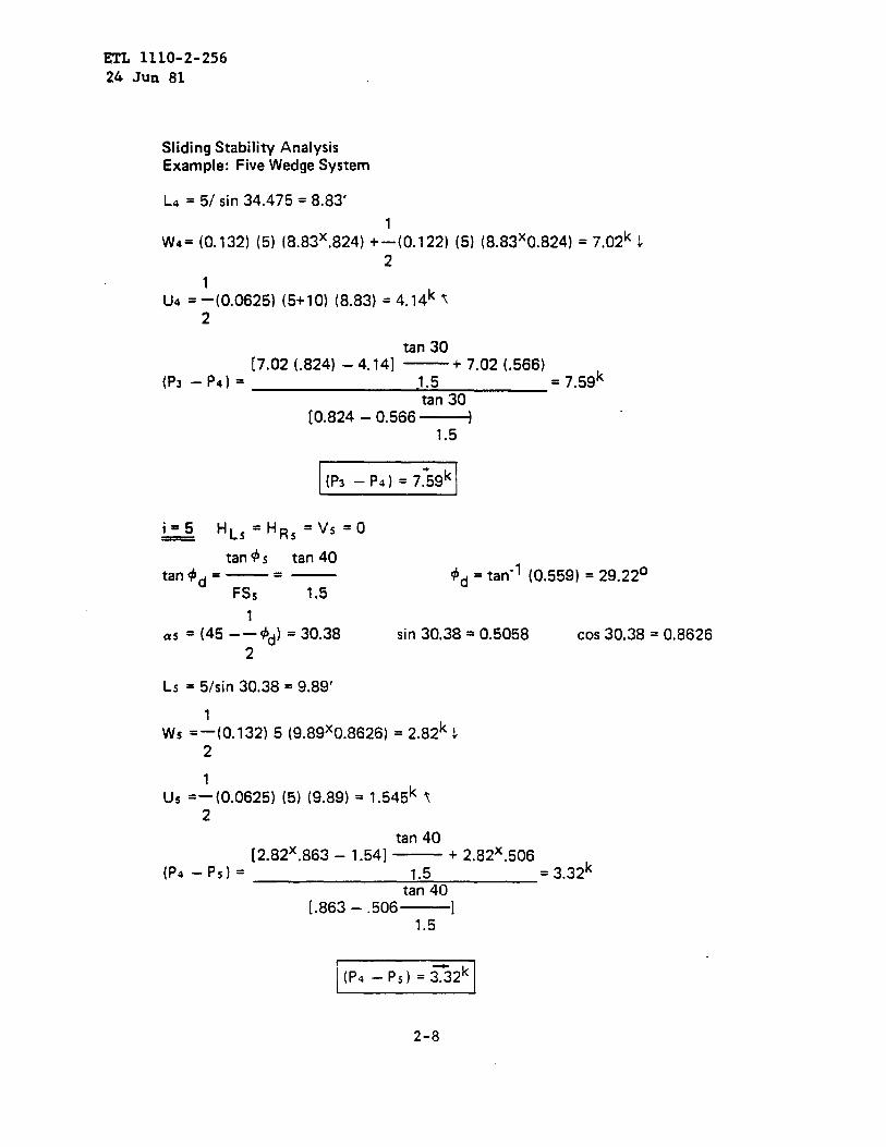
LA = 5/ sin 34.475 = 8.83’
1
W4= (0.132) (5) (8.83X.824) +–(0.122) (5) (8. S3X0.824) = 7.02k J
2
U4=‘(0.0625) (5+10) (8.83) = 4.14k ~2
tan 30[7.02 (.824) -4. 14] —+ 7.o2 (,566)
(P3 –P4)= 1.5 = 7.59ktan 30
[0.824 – 0.566 ~1.5
tan 45 tan 40tan$d=—. — +d = tan-l (0.559) = 29.22°
FSS 1,5
1
a, = (45 -–+d) = 30.38 sin 30,38 = 0.5058 COS 30.38 = 0.8626
2
Ls = 51sin 30.38 = 9.89’
Ws =1(0.132) 5 (9.89X0.8626) = 2.82k 12
us =:(0.0625) (5) (9.89) = 1.545k t2
tan 40[2.82X.863 – 1.54] — + 2.82X.506
(P4-PS)= 1.5 = 3.32ktan 40
[.863 – .506 ]1.5
2-8

ETL 1110-2-25624 Jun 81
%~.,ng Stability Analysis~o~-xample: Five Wedge System
lbSummary: Wedge Forces for Trial Safety Factors
FS=l.5
i ‘i Li HLi
1 –51.82 6.36 0
2 –55.53 12.13 0
3 9.5 30.3 19.53
4 34.47 8.83 0
5 30.38 9.89 0
FS = 2.5
i ai Li H Li
1 –49.14 6.61 02 –51.5 12.78. 0
3 9.5 30.3 19.53
4 38.5 8.0 0
5 35.72 8.56 0
FS = 2.0
i ‘i Li H Li
1 –50. 16 6.51 0
2 –53.05 12.51 0
3 9.5 30.3 19.53
4 36.95 8.33 0
5 33.62 9.03 0
HRi
o0000
HRi
o0000
HRi
o
0
0
0
0
Vi
6.14
10.73
000
Vi
6.75
12.43
0
0
0
Vi
6.52
11.73
0
0
0
Wi
1.15
8.20
122.4
7.02
2.82
Wi
1.27
9.50
122.4
6.06
2.29
Wi
1.22
8.97
122.4
6.43
2.48
Ui (pi_, - Pi)
10.93 –9.01
26.53 -24.56
47.33 32.97
4.14 7.59
1.54 3.32
APR = 10.31
Ui (pi_, - Pi)
11.36 -9.10
27.95 -25.48
47.33 19.65
3.76 6.26
1.34 2.45
APR = -6.20
Ui (pi_, – ‘i)
11.19 -9.06
27.37 -25.13
47.33 24.53
3.9 6.73
1.41 2.75-
APQ = -0.1811
2-9

ETL 1110-2-256
24 Jun 81
Sliding Stability AnalysisExample: Five Wedge System
Graphical Snl~ftinm I-. ~~fety Factor
The safety factor for sliding equilibrium of the five wedge system is determine from:
5 [APR=Ov (pi_, - Pi)=JP~ .i=l [Apff*O
10
9
b
7
6
5
4
3
2
1
-1
-2
-3
-4
-5
-6
-7
Safety factor for equilibrium
For tria I safetv factors
‘\-APQ
\
2-1o
ETL 1110-2-256
24 Jun 81
ALTERNATE NETHOD OF ANALYSIS
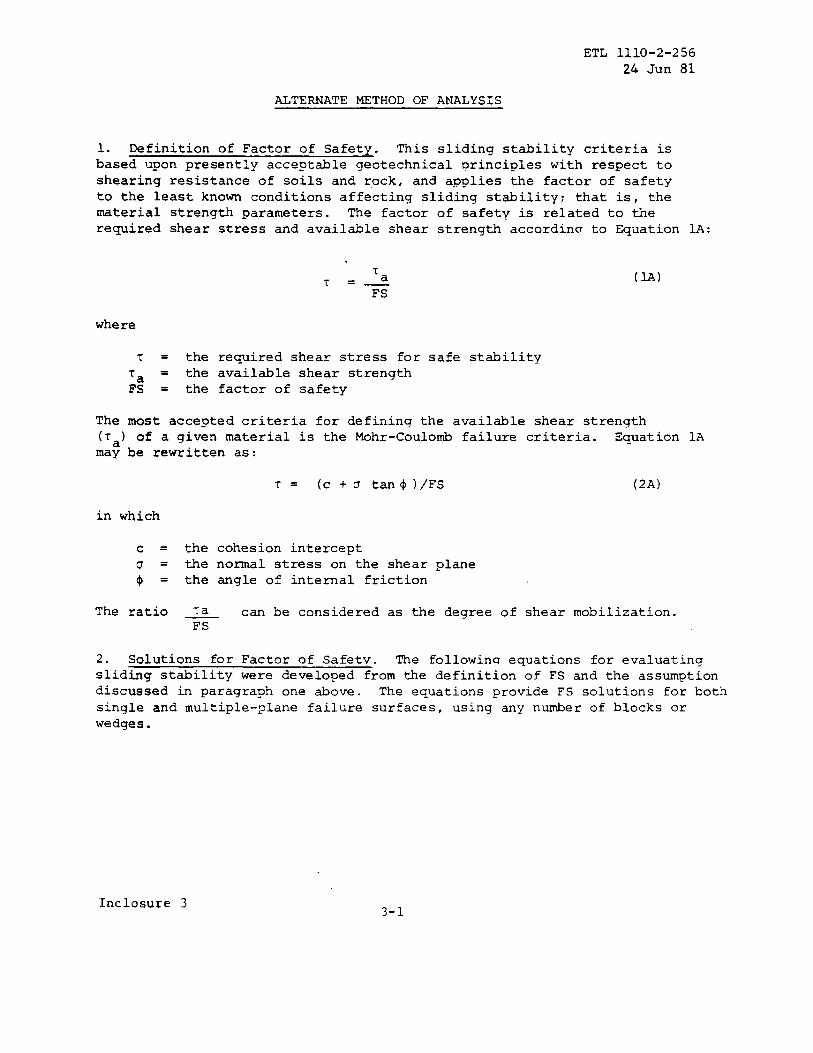
1. Definition of Factor of Safety. This sliding stability criteria isbased upon presently acceptable geotechnical principles with respect toshearing resistance of soils and rock, and applies the factor of safetyto the least known conditions affecting sliding stability; that is, thematerial strength parameters. The factor of safety is related to therequired shear stress and available shear strength accordinq to Eqaation 1A:
TT
a=—FS
(M)
where
T = the required shear stress for safe stability
‘a = the available shear strengthFs = the factor of safety
The most accepted criteria for defining the available shear strength(’ra)of a given material is the Mohr-Coulomb failure criteria. Equation 1Amay be rewritten as:
‘r= (c +U tan$)\FS (2A)
in which
c = the cohesion interceptu = the normal stress on the shear plane
$ = the angle of internal friction
The ratio ~a can be considered as the degree of shear mobilization.FS
2. Solutions for Factor of Safetv. The followinu equations for evaluatingsliding stability were developed from the definition of FS and the assumptiondiscussed in paragraph one above. The equations provide FS solutions for bothsingle and multiple-plane failure surfaces, using any nuxnber of blocks orwedges.
Inclosure 33-1

ETL 1110-2-25624 Jun 81
a. Notation:
c =
u.
A=
v=
H =
a =
$ =
i=
N.
the cohesion intercept
the uplift force acting under a wedge on the critical potentialfailure plane = uplift pressure x area of critical ?otentialfailure plane
the area of the critical potential failure plane
all applied vertical forces (body and surcharqe) acting onan individual wedge
all applied horizontal forces acting on an individual wedge
the angle between the inclined plane of the cr’itical potentialfailure surface and the horizontal (a > 0 for upslope sliding;a < 0 for downslope sliding)
the angle of internal friction along the critical potentialfailure plane considered
the subscript associated with planar segments along thecritical potential failure surface
the number of wedqes in the failure mechanism or number ofplanes making up the critical potential failure surface
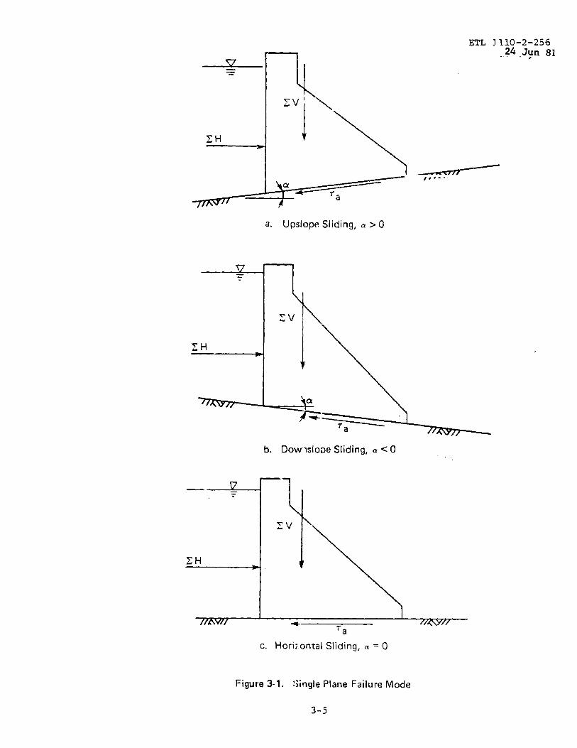
b. Case 1: Single-Plane Failure Surface. Figure 3-1 shows a graphicalrepresentation of a single-plane failure mode. Here the critical potentialfailure surface is defined by a single plane at the interface between thestructure and foundation material with no embedment. Equation 3A providesa direct solution for FS for inclined failure glanes.
FS =CA + (V cos a - U+Hsina)tan$
H cos a - V sin a(3A)
For the case where the critical ,potential failure surface can be defined asa horizontal plane (a = O) , Equation 3A reduces to Equation 4A:
FS =CA + (V - U) tan $ (4A)
H
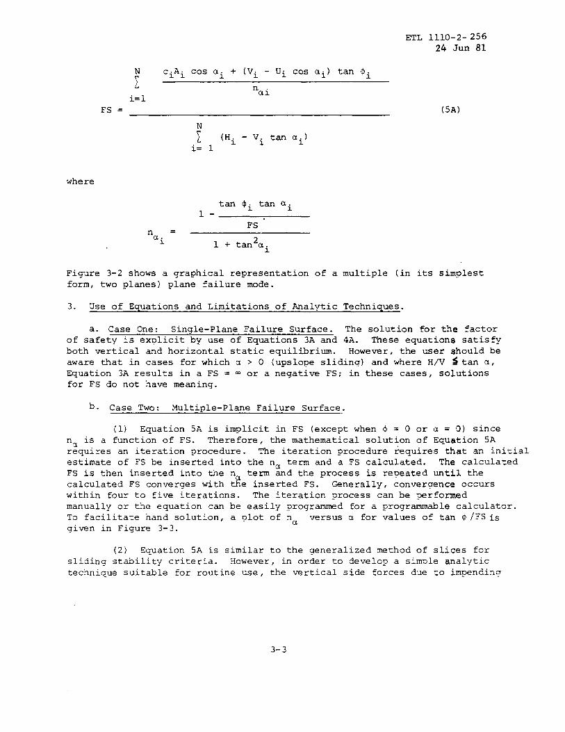
c. Case 2: Multiple-Plane Failure Surface. This general case isapplicable to situations where the structure is embedded andior where thecritical ~tential failure surface is defined by two or more weak planes.The solution for FS is obtained ~rom Equation 5A:
3-2
ETL 1110-2-25624 Jun 81
! ciAicosai+(v:-uicosai)‘an$iai
i=1
FS =
~ (Hi- Vi tan ai)i= 1
where
tan $i tan ai1-
FS -n .a. .-. /
Figure 3-2 showsform, two planes
(5A)
L 1 + tan’ai
a graphical representation of a multiple (in its simplestplane failure mode.
3. Use of Equations and Limitations of Analvtic Techniques.
a. Case One: Single-Plane Failure Surface. The solution for the factorof safety is explicit by use of Equations 3A and 4A. These equations satisfyboth vertical and horizontal static equilibria. However, the user should beaware that in cases for which a > 0 (upslope slidinq) and where H/V ~ tan a,Equation 3A results in a FS = ~ or a negative FS; in these cases, solutionsfor FS do not have meaning.
b. Case Two: Multiple-Plane Failure Surface.
(1) Equation 5A is implicit in FS (except when @ = O or a = O) sincen is a function of FS. Thereforer the mathematical solution of Equation 5Ar~quires an iteration procedure. The iteration procedure requires that an initialestimate of FS be inserted into the na term and a FS calculated. The calculatedFS is then inserted into the na term and the process is repeated until thecalculated FS converges with the inserted FS. Generally, convergence occurswithin four to five iterations. The iteration process can be performedmanually or the equation can be easily programmed for a programmable calculator.To facilitate hand solution, a plot of nu versus a for values of tan 4 IFS isgiven in Figure 3-3.
(2) Equation 5A is similar to the generalized method of slices forsliding stability criteria. However, in order to develop a simple analytictechnique suitable for routine use, the vertical side forces due to impending
3-3

motion of the wedges between slices were assumed to be zero. Therefore ,although the equation satisfies complete horizontal static equilibrium,complete vertical equilibrium is in general not satisfied. The FS computed
from Equation 5A will be slightly lower than the FS computed from the morecomplicated techniques which completely satisfy both vertical and horizontalstatic equilibria.
(3) The user should be aware that Equation 5A will yield identicalsolutions for FS with the methods described in the main body of this ETL.The governing wedge equation (equation seven) , together with the boundaryconditions (equations three and four) to have the system of wedges act asan integral failure mechanism, is mathematically equivalent to Equation 5A.The user may find the more convenient method to be a function of the designsituation. Since solutions for FS by these two methods of analysis areidentical, and since the mathematical approach is quite different, one caneffectively be used as a check on the other.
3-4
ETL 1110-2-256..?4.Jyn 81
a. Upslope Sliding, ~>0
b. Dowlslo~eSliding, a<O
c. Horizontal Sliding, m = O
Figure 3-1. !;ingle Plane Failure Mode
3-5

ETL 1110-2-256
24 Jun 81
v=.
Hm
d—. wedge 1 wedge 2._9
VI
!
- Segment 2//v
Tension Crack ~
Sign convention: ‘al4
al < 0, downslope sliding
a: > 0, upslope sliding
Figure 3-2. Multiple Plane Failure Mode in the Simpllst Form of Two Planes.
3-6

ETL 1110-2-25624 Jun 81
1,2
1.0
0.8
r1.0
0.6 0.8
0.6Tznd
—7FSI c.:
0.4
L
0.2
0
0.2
–60
tan+1–—
FStan a
“.0
1 + ~an2 a
yR/’/// //
/
/
Down Slope Slldlng
+Up Slope Slidlng
–40 -20 0 20 40 6(
a (degrees)
80
Fi~re 3-3. Plot of n= and u for Values of tan@/FS
3-7