Embed Size (px)
Citation preview
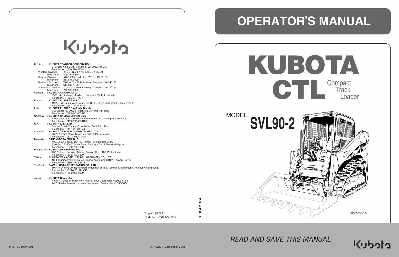
U.S.A. : KUBOTA TRACTOR CORPORATION3401 Del Amo Blvd., Torrance, CA 90503, U.S.A.Telephone : (310)370-3370
Canada : KUBOTA CANADA LTD.5900 14th Avenue, Markham, Ontario, L3S 4K4, CanadaTelephone : (905)294-7477
France : KUBOTA EUROPE S.A.S19-25, Rue Jules Vercruysse, Z.I. BP88, 95101 Ar enteuil Cedex, FranceTelephone : (33)1-3426-3434
Italy : KUBOTA EUROPE S.A.S Italy BranchVia Grandi, 29 20068 Peschiera Borrome (MI) ItalyTelephone : (39)02-51650377
Germany : KUBOTA BAUMASCHINEN GmbHSteinhauser str, 100, 66482 Zweibrucken Rheinlandpfalz GermanyTelephone : (49)6332-4870100
U.K. : KUBOTA (U.K.) LTD.Dormer Road, Thame, Oxfordshire, OX9 3UN, U.K.Telephone : (44)1844-214500
Australia : KUBOTA TRACTOR AUSTRALIA PTY LTD.25-29 Permas Way, Tru anina, VIC 3029, AustraliaTelephone : (61)-3-9394-4400
Malaysia : SIME KUBOTA SDN. BHD.No.3 Jalan Sepadu 25/123 Taman Perindustrian Axis,Seksyen 25, 40400 Shah Alam, Selan or Darul Ehsan MalaysiaTelephone : (60)3-736-1388
Philippines : KUBOTA PHILIPPINES, INC.232 Quirino Hi hway, Baesa, Quezon City 1106, PhilippinesTelephone : (63)2-422-3500
Taiwan : SHIN TAIWAN AGRICULTURAL MACHINERY CO., LTD.16, Fen pin 2nd Rd, Taliao Shian Kaohsiun 83107, Taiwan R.O.C.Telephone : (886)7-702-2333
Thailand : SIAM KUBOTA CORPORATION CO., LTD.101/19-24 Moo 20, Navanakorn Industrial Estate, Tambon Khlon nuen , Amphur Khlon luan ,Pathumthani 12120, THAILANDTelephone : (66)2-909-0300
Japan : KUBOTA CorporationFarm & Industrial Machinery International Operations Headquarters2-47, Shikitsuhi ashi 1-chome, Naniwa-ku, Osaka, Japan 556-8601
Western Division : 1175 S. Guild Avc., Lodi, CA 95240Telephone : (209)334-9910
Central Division : 14855 FAA Blvd., Fort Worth, TX 76155Telephone : (817)571-0900
Northern Division : 6300 at One Kubota Way, Groveport, OH 43125Telephone : (614)835-1100
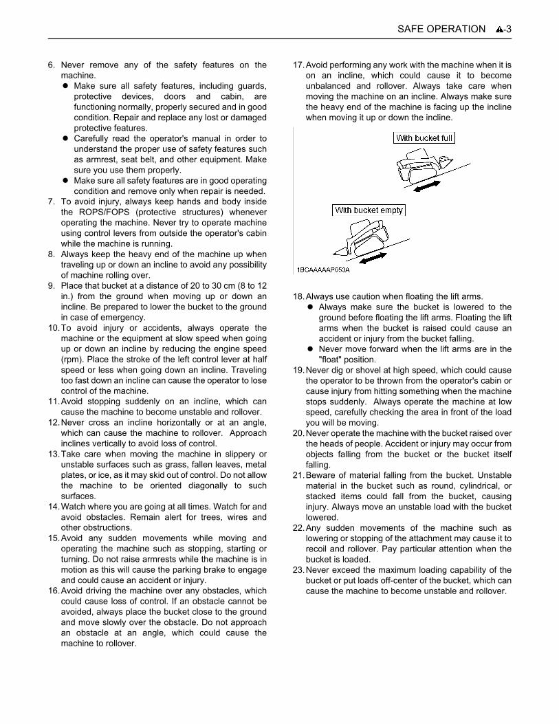
Southeast Division : 1025 Northbrook Parkway, Suwanee, GA 30024Telephone : (770)995-8855
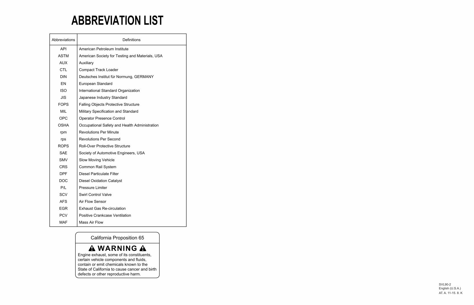
ABBREVIATION LISTAbbreviations Definitions
API
ASTM
AUX
CTL
DIN
EN
ISO
JIS
FOPS
MIL
OPC
OSHA
rpm
rps
ROPS
SAE
SMV
CRS
DPF
DOC
P/L
SCV
AFS
EGR
PCV
MAF
American Petroleum Institute
American Society for Testing and Materials, USA
Auxiliary
Compact Track Loader
Deutsches Institut für Normung, GERMANY
European Standard
International Standard Organization
Japanese Industry Standard
Falling Objects Protective Structure
Military Specification and Standard
Operator Presence Control
Occupational Safety and Health Administration
Revolutions Per Minute
Revolutions Per Second
Roll-Over Protective Structure
Society of Automotive Engineers, USA
Slow Moving Vehicle
Common Rail System
Diesel Particulate Filter
Diesel Oxidation Catalyst
Pressure Limiter
Swirl Control Valve
Air Flow Sensor
Exhaust Gas Re-circulation
Positive Crankcase Ventilation
Mass Air Flow
California Proposition 65
Engine exhaust, some of its constituents,certain vehicle components and fluids,contain or emit chemicals known to theState of California to cause cancer and birthdefects or other reproductive harm.
WARNING
�������
��� � ��������
��� �� ������ �� �
���������

UNIVERSAL SYMBOLSAs a guide to the operation of your machine, various universal symbols have been utilized on the instruments and controls. The symbols are shown below with an indication of their meaning.
Caution
Engine, Electrical Preheat
Engine Lubricating Oil Pressure
Coolant Temperature
Hydraulic Oil Temperature
Hydraulic Lock
Hydraulic Unlock
AUX Hydraulics
High-Flow
AUX Hold
AUX Electrical Power
Fuel
Diesel Fuel
Fast (Speed Indicator)
Slow (Speed Indicator)
Battery Charge
DPF Standby / Regeneration
Engine Rev up
Inhibit DPF Regeneration
Parking Brake
Front Working Light
Rear Working Light
Lock
Unlock
Forward
Backward
Turn Right
Turn Left
Lift Arm Raise
Lift Arm Lower
Loader Bucket, Dump
Loader Bucket, Rollback
Loader Bucket, Float
Quick Hitch Lock
Horn

Legal DisclaimerTo the best of Kubota's knowledge, all information included in this publication is either owned by Kubota or falls under the fair use or public domain guidelines of copyright law in the country of sales. Kubota strives for accuracy but cannot be held responsible for any errors in information featured in this publication. Kubota notes that specifications and technical information is subject to change without notice and Kubota does not represent or warrant that the information in this publication is completely accurate or current. While Kubota used reasonable efforts to include accurate and up to date information in this publication, Kubota disclaims all representations and warranties, whether express or implied, including, but not limited to, warranties of merchantability and fitness for a particular purpose. Kubota shall not be liable for any damages, whether compensatory, direct, indirect, incidental, special, or consequential, arising out of or in connection with the use of this publication, or the information therein. If and to the extent any State, Province, or any sub-division of the country does not permit the exclusion or limitation of liability for consequential or incidental damages, Kubota's liability, in such State, Province, or any sub-division of the country, shall be limited to the fullest extent permitted by law.
The collection, arrangement and assembly of content in this publication are the exclusive property of Kubota and are likewise protected by copyright and other intellectual property laws. Kubota asserts a claim of copyright for its compilations of materials, their unique scope and style, its domains, its site design, HTML, database design, look and feel, and back-end code. Copying, distributing, re-creating or any other unauthorized use of the content of this publication without the express written consent of Kubota is strictly prohibited.
The Product(s) described in this Operator's Manual are designed and manufactured only for the country in which they are initially wholesaled by Kubota or one of its affiliated companies. Neither Kubota Corporation nor its affiliated companies provide parts, warranty or service for any Product which is re-sold or retailed in any country other than the country for which the Product(s) were designed or manufactured.
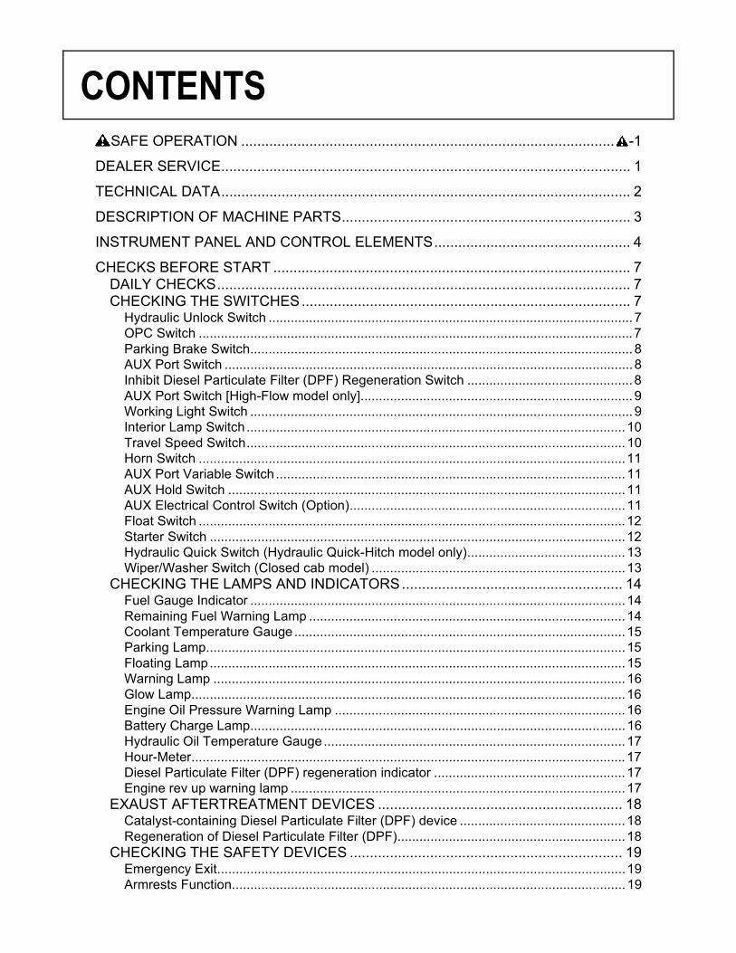
CONTENTS
SAFE OPERATION ............................................................................................. -1DEALER SERVICE...................................................................................................... 1
TECHNICAL DATA...................................................................................................... 2
DESCRIPTION OF MACHINE PARTS........................................................................ 3
INSTRUMENT PANEL AND CONTROL ELEMENTS................................................. 4
CHECKS BEFORE START ......................................................................................... 7DAILY CHECKS....................................................................................................... 7CHECKING THE SWITCHES.................................................................................. 7
Hydraulic Unlock Switch ................................................................................................... 7OPC Switch ...................................................................................................................... 7Parking Brake Switch........................................................................................................ 8AUX Port Switch ...............................................................................................................8Inhibit Diesel Particulate Filter (DPF) Regeneration Switch ............................................. 8AUX Port Switch [High-Flow model only].......................................................................... 9Working Light Switch ........................................................................................................ 9Interior Lamp Switch....................................................................................................... 10Travel Speed Switch....................................................................................................... 10Horn Switch ....................................................................................................................11AUX Port Variable Switch ............................................................................................... 11AUX Hold Switch ............................................................................................................ 11AUX Electrical Control Switch (Option)........................................................................... 11Float Switch .................................................................................................................... 12Starter Switch .................................................................................................................12Hydraulic Quick Switch (Hydraulic Quick-Hitch model only)........................................... 13Wiper/Washer Switch (Closed cab model) .....................................................................13
CHECKING THE LAMPS AND INDICATORS....................................................... 14Fuel Gauge Indicator ...................................................................................................... 14Remaining Fuel Warning Lamp ...................................................................................... 14Coolant Temperature Gauge.......................................................................................... 15Parking Lamp.................................................................................................................. 15Floating Lamp................................................................................................................. 15Warning Lamp ................................................................................................................ 16Glow Lamp......................................................................................................................16Engine Oil Pressure Warning Lamp ............................................................................... 16Battery Charge Lamp...................................................................................................... 16Hydraulic Oil Temperature Gauge.................................................................................. 17Hour-Meter...................................................................................................................... 17Diesel Particulate Filter (DPF) regeneration indicator .................................................... 17Engine rev up warning lamp ........................................................................................... 17
EXAUST AFTERTREATMENT DEVICES ............................................................. 18Catalyst-containing Diesel Particulate Filter (DPF) device ............................................. 18Regeneration of Diesel Particulate Filter (DPF).............................................................. 18
CHECKING THE SAFETY DEVICES .................................................................... 19Emergency Exit...............................................................................................................19Armrests Function........................................................................................................... 19
CONTENTS
OPC Function ................................................................................................................. 19Forced Lift Arms Lowering Device.................................................................................. 20
DOOR AND WINDOWS......................................................................................... 20Opening/Closing of Cab Door (Closed cab model)......................................................... 20Opening/Closing of Side Cab Window (Closed cab model) ........................................... 22
AIR-CONDITIONER............................................................................................... 22Air Flow........................................................................................................................... 22Air Control Vent .............................................................................................................. 23Control Panel ..................................................................................................................24Operation ........................................................................................................................25
OPERATION OF THE ENGINE................................................................................. 26STARTING THE ENGINE...................................................................................... 26
Checkpoints after Starting the Engine ............................................................................ 27STARTING THE ENGINE UNDER COLD CONDITIONS...................................... 28STOPPING THE ENGINE...................................................................................... 28STARTING WITH AN AUXILIARY BATTERY ....................................................... 28
Observe Following Guidelines when Starting with an Auxiliary Battery.......................... 28
OPERATION OF THE MACHINE.............................................................................. 29RUNNING-IN OF THE MACHINE.......................................................................... 29
Do not Work with Full Engine Rpm's or Full Loads during the First 50 Working Hours..29Oil Change in the Run-in Stage ...................................................................................... 29
STARTING............................................................................................................. 29Adjusting the Operator's Seat.........................................................................................29Seat Belt ......................................................................................................................... 30Armrest ........................................................................................................................... 30
DRIVING ................................................................................................................ 31Forward and Backward Travel........................................................................................ 31
TURNING............................................................................................................... 32Pivot Turn ....................................................................................................................... 32Spin Turn ........................................................................................................................33
OPERATION OF THE LIFT ARMS........................................................................ 33Lift Arm Stopper.............................................................................................................. 34
OPERATION OF THE BUCKET ............................................................................ 35AUXILIARY HYDRAULIC CONTROL.................................................................... 36
Auxiliary Hydraulic Control Operation............................................................................. 37ATTACHMENT CONTROL DEVICE (OPTION) .................................................... 38MECHANICAL QUICK-HITCH............................................................................... 38
Attaching Attachments....................................................................................................38Detaching Attachments................................................................................................... 40
HYDRAULIC QUICK-HITCH (OPTION)................................................................. 40Attaching Attachments....................................................................................................40Detaching Attachments................................................................................................... 42
IMPORTANT INFORMATION ON MACHINE OPERATION.................................. 42Caution While Traveling.................................................................................................. 42Precaution When Traveling in High Speed.....................................................................43Precautions for Use of Machine Near Water .................................................................. 43Precaution When Traveling on Inclines .......................................................................... 43Parking on an Incline ...................................................................................................... 44Prohibited Actions........................................................................................................... 44Preventing Slippage of Rubber Tracks ........................................................................... 44

CONTENTS
LIFTING THE MACHINE ........................................................................................... 45
TRANSPORTING THE MACHINE ............................................................................ 48LOADING THE MACHINE ON A TRANSPORT VEHICLE.................................... 48TOWING AN OPERABLE MACHINE .................................................................... 50TOWING AN INOPERABLE MACHINE................................................................. 50
MAINTENANCE......................................................................................................... 51MAINTENANCE INTERVALS................................................................................ 51OPENING AND CLOSING OF COMPONENTS .................................................... 54
Rear Door ....................................................................................................................... 54Engine Hood ................................................................................................................... 55Radiator and Oil Cooler .................................................................................................. 55Where to Keep Operator's Manual ................................................................................. 56Tool Box..........................................................................................................................56Tilting Up the CAB .......................................................................................................... 57
DISCHARGING MUD FROM OPERATOR ROOM AND MAIN FRAME ............... 59Operator room ................................................................................................................ 59Main Frame.....................................................................................................................59
DAILY CHECKS..................................................................................................... 59Checking Coolant Level.................................................................................................. 59Checking Fuel Level ....................................................................................................... 60Checking Engine Oil Level.............................................................................................. 60Checking Hydraulic Oil Level.......................................................................................... 61Lubrication Points ........................................................................................................... 61Checking Radiator and Oil Cooler .................................................................................. 62Checking and Cleaning Engine and Electrical Wiring..................................................... 62Checking V-belt .............................................................................................................. 62Washing Whole Machine................................................................................................ 62Draining Water Separator ............................................................................................... 62Cleaning Evacuator Valve .............................................................................................. 63Checking Dust Indicator.................................................................................................. 63Checking Diesel Particulate Filter (DPF) Muffler ............................................................ 63Checking Washer Liquid................................................................................................. 63Checking Battery Condition ............................................................................................ 64
REGULAR CHECKS AND MAINTENANCE WORK ................................................. 66EVERY 50 SERVICE HOURS ............................................................................... 66
Draining the Water from the Fuel Tank........................................................................... 66Checking Track Tension ................................................................................................. 66Inspection and Cleaning Air Cleaner Element ................................................................ 67Air Cleaner Element........................................................................................................ 68
EVERY 250 SERVICE HOURS ............................................................................. 68Checking Radiator Hoses and Clamps........................................................................... 68Checking Fuel Line and Intake Air Line.......................................................................... 69Adjusting V-belt Tension................................................................................................. 69Cleaning Inside of Main Frame....................................................................................... 70Replacing Air Cleaner Element....................................................................................... 70Cleaning Inner Air Filter .................................................................................................. 70Cleaning Air Fresh Filter ................................................................................................. 71Checking Air-Conditioner Condenser ............................................................................. 71
EVERY 500 SERVICE HOURS ............................................................................. 72Changing Engine Oil....................................................................................................... 72

CONTENTS
Replacing Engine Oil Filter Cartridge ............................................................................. 72Replacing Fuel Filter Cartridge....................................................................................... 73Changing Drive Unit Oil (First oil change: 250 hours) .................................................... 73Changing Return Filter (First filter change: 250 hours)................................................... 73Replacing Breather Filter ................................................................................................ 73Replacing Hydraulic Oil Filter (First filter change: 50 hours) .......................................... 74
EVERY 1000 SERVICE HOURS ........................................................................... 74Hydraulic Oil Change (Including Replacing Suction and Return Filter in the Hydraulic Tank)............................................................................................................................... 74Hydraulic Oil Check with Hydraulic Hammers ................................................................ 75
EVERY 1500 SERVICE HOURS ........................................................................... 75Checking Injector Tip ...................................................................................................... 75Replacing Oil Separator Element ................................................................................... 75Checking PCV (Positive Crankcase Ventilation) Valve .................................................. 76Checking EGR Cooler ....................................................................................................76
EVERY 2000 SERVICE HOURS ........................................................................... 76Checking the Alternator and Starter Motor .....................................................................76
EVERY 3000 SERVICE HOURS ........................................................................... 76Checking EGR System................................................................................................... 76Checking Turbocharger .................................................................................................. 76Cleaning Diesel Particulate Filter (DPF) ......................................................................... 76
ANNUAL SERVICING............................................................................................ 76Checking Air-Conditioner Pipes and Hoses.................................................................... 76Checking Exhaust Manifold (Cracks, Gas, Leakage and Mounting Screw) ................... 76Checking Intake Air Line for Air Leaks............................................................................ 76Checking Boost Sensor and AFS (Air Flow Sensor) ...................................................... 76Checking Condition of Diesel Particulate Filter (DPF) Muffler ........................................ 76Checking Diesel Particulate Filter (DPF) Differential Pressure Sensor and Piping for Gas Leak................................................................................................................................ 76Checking Diesel Particulate Filter (DPF) Exhaust Gas Temperature Sensor................. 76Checking EGR Piping for Gas Leak ............................................................................... 76
BIENNIAL SERVICING.......................................................................................... 77Changing Radiator Coolant ............................................................................................ 77Replacing Fuel Hose ...................................................................................................... 78Replacing Intake Air Line................................................................................................ 78Replacement of Radiator Hoses..................................................................................... 78Replacing Air-Conditioner Pipes and Hoses...................................................................79Replacement of Closed Breather Related Rubber Piping .............................................. 79Replacement of Diesel Particulate Filter (DPF) Differential Pressure Sensor Rubber Piping (Front and Back) .................................................................................................. 79Replacement of Suction pipe downstream the AFS (Air Flow Sensor) .......................... 79Replacement of Boost Sensor Pressure Rubber Piping................................................. 79Replacement of EGR Cooler Hose................................................................................. 79
SERVICING AS REQUIRED.................................................................................. 79Checking Amount of Refrigerant (gas) ........................................................................... 79Draining the fuel filter...................................................................................................... 80
OTHER ADJUSTMENTS AND REPLACEMENTS.................................................... 81PURGING OF THE FUEL SYSTEM ...................................................................... 81ADJUSTMENT OF TRACKS ................................................................................. 81FUSES ................................................................................................................... 83
Replacing Fuses .............................................................................................................83
CONTENTS
Fuse Capacities and Circuits .......................................................................................... 83Electrical Outlet...............................................................................................................84Slow Blow Fuse .............................................................................................................. 84
TROUBLESHOOTING............................................................................................... 85List of Error Code Numbers ................................................................................... 87
OPERATION UNDER COLD WEATHER CONDITIONS .......................................... 93PREPARATION FOR OPERATION IN COLD WEATHER.................................... 93PROCEDURE AFTER COMPLETION WORK ...................................................... 93
LONG STORAGE...................................................................................................... 94
RECOMMENDED OILS............................................................................................. 96
APPENDICES............................................................................................................ 98MAIN DIMENSIONS .............................................................................................. 98
-1SAFE OPERATION
SAFE OPERATION
Careful operation is your best insurance against anaccident.Read and understand this section carefully, beforeoperating the machine.Every user, however experienced, should carefully readand understand this section and those of the attachmentsand accessories before taking the machine into operation.The owner is obliged to inform the operators of theseinstructions in detail.Keep this manual in the storage place. (See "Where tokeep Operator's Manual" in "MAINTENANCE" section.)1. Know your equipment and its limitations. Read andunderstand this entire manual before attempting tostart and operate the machine.
2. Obey the danger, warning and caution labels on themachine.
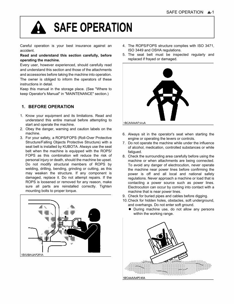
3. For your safety, a ROPS/FOPS (Roll-Over ProtectiveStructure/Falling Objects Protective Structure) with aseat belt is installed by KUBOTA. Always use the seatbelt when the machine is equipped with the ROPS/FOPS as this combination will reduce the risk ofpersonal injury or death, should the machine be upset.Do not modify structural members of ROPS bywelding, drilling, bending, grinding or cutting, as thismay weaken the structure. If any component isdamaged, replace it. Do not attempt repairs. If theROPS is loosened or removed for any reason, makesure all parts are reinstalled correctly. Tightenmounting bolts to proper torque.
4. The ROPS/FOPS structure complies with ISO 3471,ISO 3449 and OSHA regulations.
5. The seat belt must be inspected regularly andreplaced if frayed or damaged.
6. Always sit in the operator's seat when starting theengine or operating the levers or controls.
7. Do not operate the machine while under the influenceof alcohol, medication, controlled substances or whilefatigued.
8. Check the surrounding area carefully before using themachine or when attachments are being connected.To avoid any danger of electrocution, never operatethe machine near power lines before confirming thepower is off and all local and national safetyregulations. Never approach a machine or load that iscontacting a power source such as power lines.Electrocution can occur by coming into contact with amachine that is near power lines.
9. Check for buried pipes and cables before digging.10.Check for hidden holes, obstacles, soft underground,
and overhangs. Do not enter soft ground.A During machine use, do not allow any persons
within the working range.
1. BEFORE OPERATION
SAFE OPERATION-2
11.Do not allow anyone to use the machine until theyhave been informed of the work to be performed andthey have read and understood the operator's manual.
12.Do not wear baggy, torn or oversized clothing whenworking with the machine as such clothing can getcaught in rotating parts or control elements which cancause accidents or injuries. Wear adequate safetyclothing, e.g. safety helmet, safety shoes, eyeprotection, ear protection, working gloves, etc, asnecessary and as prescribed by law or statutes.
13.Do not allow passengers to ride on any part of themachine at any time. The operator must remain in themachine seat during operation.
14.Check the levers, pedals and mechanical parts forcorrect adjustments and wear. Replace worn ordamaged parts immediately. Check the nuts and boltsregularly for correct torque.
15.Keep your machine clean. Heavy soiling, grease, dustand grass can cause fires, accidents or injuries.
16.Before starting the machine, be absolutely sure thatthe machine has been filled with fuel, lubricated,greased and undergone all necessary maintenance.
17.Do not modify the machine, otherwise it could lead tounforeseen safety problems.
18.Make sure attachments, particularly those utilizingquick-hitch, are securely mounted. Use only KUBOTAauthorized attachments.
1. Mount and dismount the machine safely. Always facethe machine. Always use handrails and availablesteps and keep yourself well balanced. Do not grab orhold any of the control levers and switches. Do notjump on or off the machine, whether stationary or inmotion.
2. Start and control the machine only from the operator'sseat. The operator should not lean out of his/her seatwhen the engine is running.
3. Before starting the engine, make sure that thearmrests are in the "Raised" position and the controllevers are in their neutral position and the seat belt isfastened correctly.
4. Always thoroughly check the surrounding area for anypossible conditions that could create a dangeroussituation. A Make sure you read the operator's manual to
thoroughly understand the operating conditionsand limitations of the machine.
A To avoid damage and to prevent accidents, alwaysuse the buddy system and have the other person,check for clearances and other possible dangersthat may be obstructed from view.
A Never allow people to approach the vicinity of theturning radius of the machine.
A Be cognizant of blind spots to the rear and alwayscheck behind you before backing up.
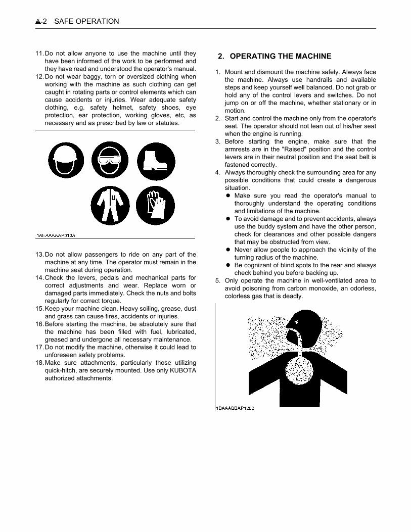
5. Only operate the machine in well-ventilated area toavoid poisoning from carbon monoxide, an odorless,colorless gas that is deadly.
2. OPERATING THE MACHINE
-3SAFE OPERATION
6. Never remove any of the safety features on themachine.A Make sure all safety features, including guards,
protective devices, doors and cabin, arefunctioning normally, properly secured and in goodcondition. Repair and replace any lost or damagedprotective features.
A Carefully read the operator's manual in order tounderstand the proper use of safety features suchas armrest, seat belt, and other equipment. Makesure you use them properly.
A Make sure all safety features are in good operatingcondition and remove only when repair is needed.
7. To avoid injury, always keep hands and body insidethe ROPS/FOPS (protective structures) wheneveroperating the machine. Never try to operate machineusing control levers from outside the operator's cabinwhile the machine is running.
8. Always keep the heavy end of the machine up whentraveling up or down an incline to avoid any possibilityof machine rolling over.
9. Place that bucket at a distance of 20 to 30 cm (8 to 12in.) from the ground when moving up or down anincline. Be prepared to lower the bucket to the groundin case of emergency.
10.To avoid injury or accidents, always operate themachine or the equipment at slow speed when goingup or down an incline by reducing the engine speed(rpm). Place the stroke of the left control lever at halfspeed or less when going down an incline. Travelingtoo fast down an incline can cause the operator to losecontrol of the machine.
11.Avoid stopping suddenly on an incline, which cancause the machine to become unstable and rollover.
12.Never cross an incline horizontally or at an angle,which can cause the machine to rollover. Approachinclines vertically to avoid loss of control.
13.Take care when moving the machine in slippery orunstable surfaces such as grass, fallen leaves, metalplates, or ice, as it may skid out of control. Do not allowthe machine to be oriented diagonally to suchsurfaces.
14.Watch where you are going at all times. Watch for andavoid obstacles. Remain alert for trees, wires andother obstructions.
15.Avoid any sudden movements while moving andoperating the machine such as stopping, starting orturning. Do not raise armrests while the machine is inmotion as this will cause the parking brake to engageand could cause an accident or injury.
16.Avoid driving the machine over any obstacles, whichcould cause loss of control. If an obstacle cannot beavoided, always place the bucket close to the groundand move slowly over the obstacle. Do not approachan obstacle at an angle, which could cause themachine to rollover.
17.Avoid performing any work with the machine when it ison an incline, which could cause it to becomeunbalanced and rollover. Always take care whenmoving the machine on an incline. Always make surethe heavy end of the machine is facing up the inclinewhen moving it up or down the incline.
18.Always use caution when floating the lift arms.A Always make sure the bucket is lowered to the
ground before floating the lift arms. Floating the liftarms when the bucket is raised could cause anaccident or injury from the bucket falling.
A Never move forward when the lift arms are in the"float" position.
19.Never dig or shovel at high speed, which could causethe operator to be thrown from the operator's cabin orcause injury from hitting something when the machinestops suddenly. Always operate the machine at lowspeed, carefully checking the area in front of the loadyou will be moving.
20.Never operate the machine with the bucket raised overthe heads of people. Accident or injury may occur fromobjects falling from the bucket or the bucket itselffalling.
21.Beware of material falling from the bucket. Unstablematerial in the bucket such as round, cylindrical, orstacked items could fall from the bucket, causinginjury. Always move an unstable load with the bucketlowered.
22.Any sudden movements of the machine such aslowering or stopping of the attachment may cause it torecoil and rollover. Pay particular attention when thebucket is loaded.
23.Never exceed the maximum loading capability of thebucket or put loads off-center of the bucket, which cancause the machine to become unstable and rollover.
SAFE OPERATION-4
24.Never attempt to undercut a high embankment.Always carefully check the area for conditions thatcould cause the ground to cave-in.
A Never operate in areas where there is a possibility offalling rock.
A Never attempt to operate or drive the machine onunstable surfaces such as cliffs, shoulder of roads,deep trenches, etc. The machine could lose stabilityfrom unstable ground or vibration underneath, caus-ing it to rollover or fall.(1) Ground surfaces are especially unstable after
heavy rain or explosions.(2) Embankments and trenches may cause instabil-
ity of the ground around the area.25.Always operate the machine a safe, low speed,
especially in congested or closed in areas where thereis a danger of hitting or running into something. Payclose attention to obstructions
26.Pay particular attention when passing through tunnelsor moving the machine near high walls to avoid hittingit and causing accident or injury.Always check height and width dimensions of themachine against tunnels or any other narrow spacesthrough which the machine is to be moved in order toavoid accident or injury from hitting an obstruction.
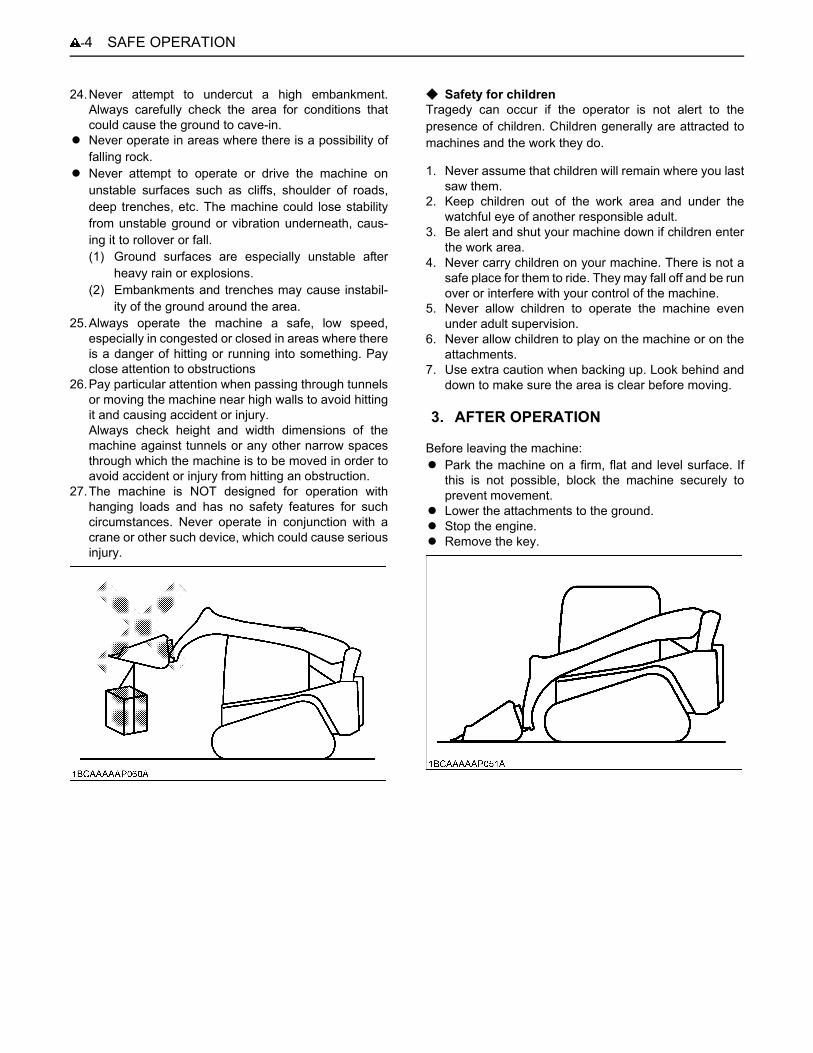
27.The machine is NOT designed for operation withhanging loads and has no safety features for suchcircumstances. Never operate in conjunction with acrane or other such device, which could cause seriousinjury.
C Safety for childrenTragedy can occur if the operator is not alert to thepresence of children. Children generally are attracted tomachines and the work they do.
1. Never assume that children will remain where you lastsaw them.
2. Keep children out of the work area and under thewatchful eye of another responsible adult.
3. Be alert and shut your machine down if children enterthe work area.
4. Never carry children on your machine. There is not asafe place for them to ride. They may fall off and be runover or interfere with your control of the machine.
5. Never allow children to operate the machine evenunder adult supervision.
6. Never allow children to play on the machine or on theattachments.
7. Use extra caution when backing up. Look behind anddown to make sure the area is clear before moving.
Before leaving the machine:A Park the machine on a firm, flat and level surface. If
this is not possible, block the machine securely toprevent movement.
A Lower the attachments to the ground.A Stop the engine.A Remove the key.
3. AFTER OPERATION
-5SAFE OPERATION
1. Observe all regulations concerning the transport of themachine on public roads.
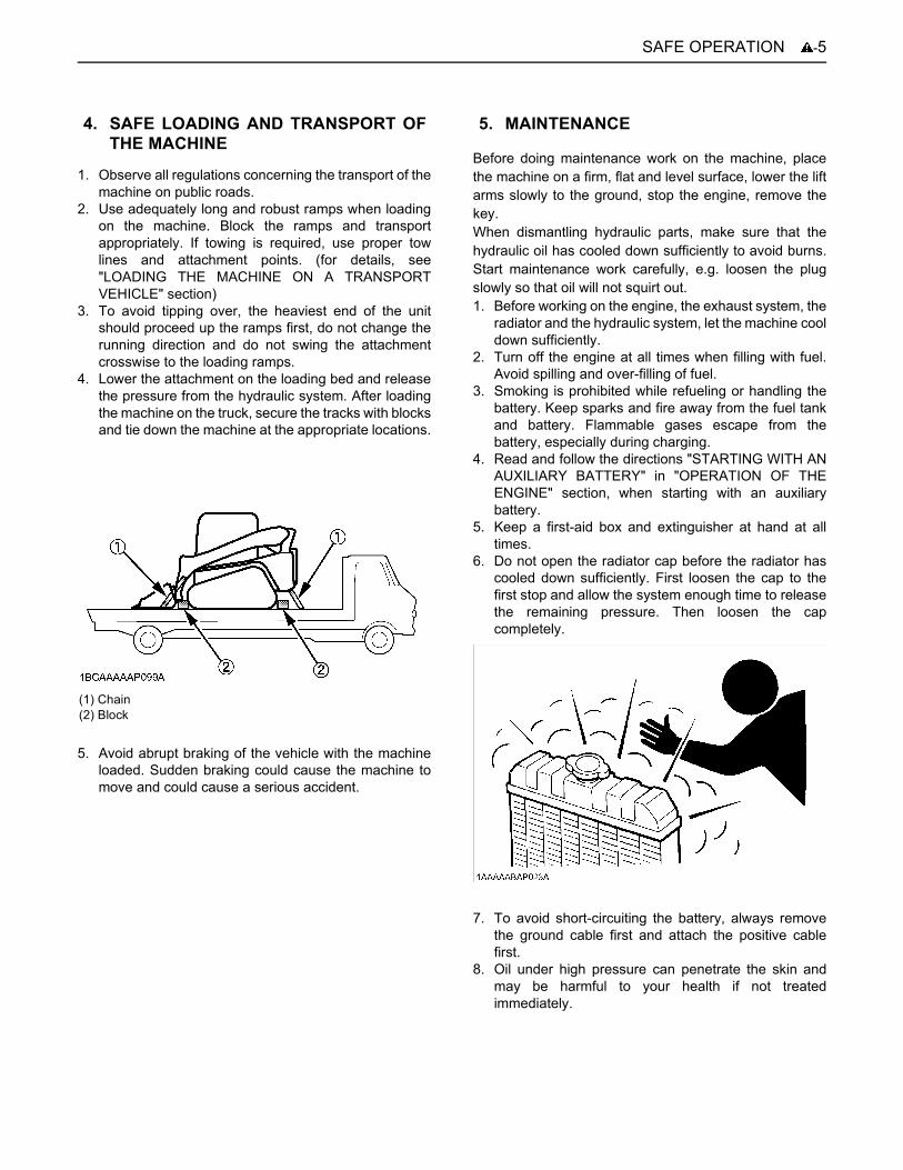
2. Use adequately long and robust ramps when loadingon the machine. Block the ramps and transportappropriately. If towing is required, use proper towlines and attachment points. (for details, see"LOADING THE MACHINE ON A TRANSPORTVEHICLE" section)
3. To avoid tipping over, the heaviest end of the unitshould proceed up the ramps first, do not change therunning direction and do not swing the attachmentcrosswise to the loading ramps.
4. Lower the attachment on the loading bed and releasethe pressure from the hydraulic system. After loadingthe machine on the truck, secure the tracks with blocksand tie down the machine at the appropriate locations.
5. Avoid abrupt braking of the vehicle with the machineloaded. Sudden braking could cause the machine tomove and could cause a serious accident.
Before doing maintenance work on the machine, placethe machine on a firm, flat and level surface, lower the liftarms slowly to the ground, stop the engine, remove thekey.When dismantling hydraulic parts, make sure that thehydraulic oil has cooled down sufficiently to avoid burns.Start maintenance work carefully, e.g. loosen the plugslowly so that oil will not squirt out.1. Before working on the engine, the exhaust system, the
radiator and the hydraulic system, let the machine cooldown sufficiently.
2. Turn off the engine at all times when filling with fuel.Avoid spilling and over-filling of fuel.
3. Smoking is prohibited while refueling or handling thebattery. Keep sparks and fire away from the fuel tankand battery. Flammable gases escape from thebattery, especially during charging.
4. Read and follow the directions "STARTING WITH ANAUXILIARY BATTERY" in "OPERATION OF THEENGINE" section, when starting with an auxiliarybattery.
5. Keep a first-aid box and extinguisher at hand at alltimes.
6. Do not open the radiator cap before the radiator hascooled down sufficiently. First loosen the cap to thefirst stop and allow the system enough time to releasethe remaining pressure. Then loosen the capcompletely.
7. To avoid short-circuiting the battery, always removethe ground cable first and attach the positive cablefirst.
8. Oil under high pressure can penetrate the skin andmay be harmful to your health if not treatedimmediately.
4. SAFE LOADING AND TRANSPORT OFTHE MACHINE
(1) Chain(2) Block
5. MAINTENANCE
SAFE OPERATION-6
9. Leaking hydraulic fluid has enough pressure topenetrate the skin and cause serious injuries.Leakages from pinholes can be totally invisible. Do notuse hands for checking for leaks. Always use a pieceof wood or cardboard. It is strongly recommended touse a face mask or eye protection. Should injuriesoccur with leaking hydraulic fluid, contact a doctorimmediately. This fluid can cause gangrene or seriousallergic reactions.
10.To avoid environmental damage from acid and heavymetals, dispose of the battery appropriately.
11.Observe all laws and regulations concerning thedisposal of used oil, coolants, solvents, hydraulicfluids, battery acids and batteries.
12.To avoid fire, do not heat the hydraulic components(tanks, pipes, hoses, cylinders) before they have beendrained and washed.
13.Use a face mask or eye protection to protect the eyesand respiratory system against dust and other foreignparticles.
14.Securely support the machine with stands or suitableblocking before working underneath. For your safety,do not work under any hydraulically supporteddevices. They can settle, suddenly leak down, or beaccidentally lowered.
15.Do not dismantle the spring of the track tensioner. Ifdismantling is necessary, contact your KUBOTAdealer where the machine was purchased, orcompetent service shop. The assembly must be doneaccording to the KUBOTA workshop manual (W.S.M.)for the product involved.
16.Always attach a "DO NOT OPERATE" tag wheneverperforming any kind of maintenance or repair.
17.Make sure you have the proper tools on hand. Do notuse defective or damaged tools, gauges, or otherdevices. Always use tools that are appropriate for thetask to be done.
18.To prevent personal injury or death, be sure to useexplosion-proof lighting when working on, inspectingor handling fuel, oil, coolant, battery fluid, etc. If theexplosion-proof lighting is not used and should break,it can ignite and cause fire, injury or death.
19.Prohibit unauthorized persons from entering the workarea to prevent injury caused by debris flying off ofmachine parts during grinding, welding, using ahammer or other such tasks.
20.Make sure work area is clear and safe. Be sure to workon a firm, level surface with adequate lighting. Work inwell-ventilated area if indoors. Make sure the area isfree from any potentially dangerous conditions such asobstacles, slippery surfaces, etc.
21.Be sure the machine is clean and free of debris.A Always remove debris from the machine and clean it
before performing any maintenance or repair work.A Before using water to wash or clean the machine, stop
engine and make sure all electrical parts and devicesare covered. Any water seepage into electrical wiringon the machine can cause a short circuit ormalfunction of controls. Never wash the battery,sensors, connectors or operator's cabin with water orsteam.
-7SAFE OPERATION
22.Always make sure the engine is stopped beforeperforming any maintenance or repairs.
A Do not attempt to lubricate or make mechanicaladjustments while the machine is in motion or whilethe engine is running even if stationary.
A If you must perform some maintenance procedureswhen the engine is running, make certain one otherperson is assisting by sitting in the operator's cabinwhile the work is being performed elsewhere on themachine. Always keep body clear of any moving partsand remove any loose clothing when working nearmoving parts to prevent possible injury.
A Always stay clear of moving parts. Clothing, hands orother parts of the body can become caught in movingparts of the machine and cause personal injury ordeath.
A Make sure to avoid any rotating fans, V-belt and othersuch moving parts. Never insert tools, fingers, hands,etc. while these parts are running.
23.Be sure to place blocks around the machine and placeprotection where components could fall.
A Always make sure the bucket is at the lowest possibleposition or on the ground before performing anymaintenance or repairs under the machine.
A Make sure the tracks are securely blocked off.A Whenever performing maintenance or repairs when
the lift arms are raised, always use the lift arm stopper. A Never do any work under a machine or work on it while
it is hoisted on jack-stands or other rigid supportdevices unless they are well secured and stable.
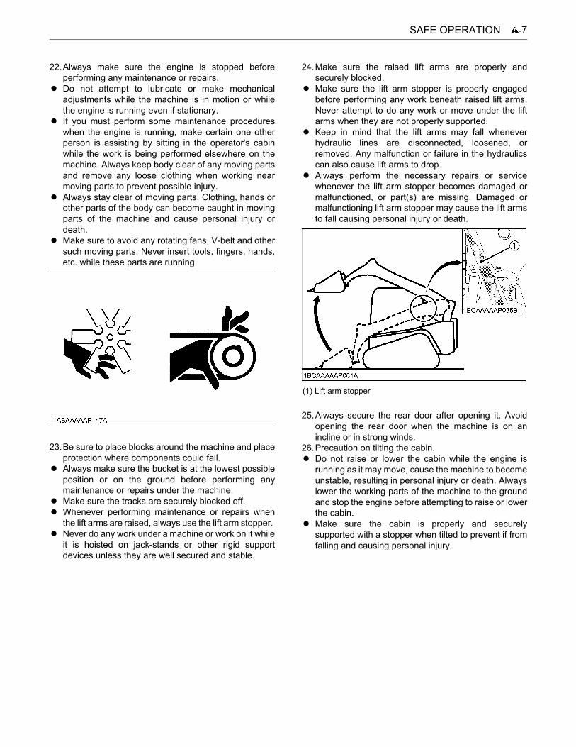
24.Make sure the raised lift arms are properly andsecurely blocked.
A Make sure the lift arm stopper is properly engagedbefore performing any work beneath raised lift arms.Never attempt to do any work or move under the liftarms when they are not properly supported.
A Keep in mind that the lift arms may fall wheneverhydraulic lines are disconnected, loosened, orremoved. Any malfunction or failure in the hydraulicscan also cause lift arms to drop.
A Always perform the necessary repairs or servicewhenever the lift arm stopper becomes damaged ormalfunctioned, or part(s) are missing. Damaged ormalfunctioning lift arm stopper may cause the lift armsto fall causing personal injury or death.
25.Always secure the rear door after opening it. Avoidopening the rear door when the machine is on anincline or in strong winds.
26.Precaution on tilting the cabin.A Do not raise or lower the cabin while the engine is
running as it may move, cause the machine to becomeunstable, resulting in personal injury or death. Alwayslower the working parts of the machine to the groundand stop the engine before attempting to raise or lowerthe cabin.
A Make sure the cabin is properly and securelysupported with a stopper when tilted to prevent if fromfalling and causing personal injury.
(1) Lift arm stopper

SAFE OPERATION-8
27.Use care when refueling.A Never smoke cigarettes or permit the use of fire while
refueling or in the vicinity of refueling.A Always make sure the engine is off and cool before
removing the fuel cap to refuel the tank. Avoid gettingfuel on any hot components.
A Keep control of the fuel filler nozzle while refueling.A Never overfill the tank with fuel. Leave room for
thermal expansion. A Always remove any excess or spilled fuel immediately.A Always make sure the fuel tank cap is securely
reinstalled. Replace the cap only with a manufacturerapproved cap whenever it becomes damaged. Use ofthe wrong type of cap may not allow for proper venting,causing pressure in the tank to build up.
A Never use fuel to clean the machine.A Always use the correct type of fuel for the machine and
the temperature in which it is being operated.
28.HosesA Leakage in any fuel, oil or hydraulic line can cause fire
or explosion.A Avoid any twisting, bending or hitting of hoses that
could cause damage to the line.A Make sure any loose connections are secure properly
before using the machine.29.Fire prevention
Compact Track Loader and some attachments havecomponents that are at high temperatures undernormal operating conditions. The primary source ofhigh temperatures is the engine and exhaust system.The electrical system, if damaged or incorrectlymaintained, can be a source of arcing or sparks.The following fire prevention guidelines will help tokeep your equipment up and running efficiently andkeep the risk of fire to a minimum.
A Blow off all accumulated debris near hot engineexhaust components such as turbocharger andexhaust manifold as well as exhaust pipes and mufflermore frequently when working in severe conditions.
A Clean out all accumulated flammable debris such asleaves, straw, pine needles, branches, bark, smallwood chips and any other combustible materials frominside the machine belly pans or lower unit structuresas well as from area in proximity to the engine.
A Inspect all fuel lines and hydraulic hoses for wear or fordeterioration. Replace them immediately if they beginto leak.
A Examine electrical wiring and connectors frequentlyfor damage. Repair any wires that are loose or frayedbefore operating the machine. Clean all electricalconnections and tighten all electrical connections asnecessary.
A Inspect the exhaust system daily for any signs ofleakage. Check for broken pipes and muffler and alsofor loose or missing bolts, nuts and clamps. If anyexhaust leaks or fractured parts are found, repairsmust be completed prior to operation.
A Always keep a multipurpose fire extinguisher on ornear the machine. Be familiar with the operation of thefire extinguisher.
30.Take care when working around hot and pressurizedcomponents.
A Always allow the engine to cool sufficiently beforeperforming any maintenance, inspection or repairs.
A Never touch any parts such as the engine, muffler,radiator, hydraulic lines, sliding parts, etc. as they maybe very hot immediately after the machine has beenrunning and can cause burning. Allow these parts tocool sufficiently before touching.
A Always use sufficient care whenever removing thecaps and plugs on the coolant, oil and hydraulic fluidas they are hot and pressurized and can causingburning and injury from spraying of hot fluid.
31.Make certain pressure from all of these systems issufficiently released before performing anymaintenance or repairs. Oil or other fluids could bereleased when caps or filters are removed before thepressure has been stabilized in the hydraulic system.
A Gradually release internal pressure build-up bystanding out of the line of any possible spray andslowly removing plugs, screws or disconnect hoses.

-9SAFE OPERATION
32.Always use care whenever handling grease that ispressurized.
A Always follow the proper procedure to adjust tension.Grease in the track adjuster is pressurized andimproper release can cause the discharge valve to flyoff, causing personal injury or death.
A Always loosen the discharge valve for the greaseslowly.
A Avoid standing in front of, or putting any parts of thebody in the line of the grease discharge valve.
A If no grease is released when discharge valve isloosened, the machine has a malfunction. DO NOTattempt to make any repairs yourself and contact thenearest dealer for repairs. Any operation of themachine under these conditions can be verydangerous.
33.Always carefully check the machine after performingany maintenance or repairs. Confirm that no oil, water,etc., is leaking from any parts that had been servicedby carefully inspecting the parts. Gradually speed upthe engine from a low speed to higher speed to checkoperation.
34.Waste materialA Always make sure any material and waste products
from the repair and maintenance of the machine arecollected into proper containers using a funnel, orother device. Dispose of waste material properly toavoid pollution and contamination of the environment.
A Consult local regulations and codes when disposing ofoil, fuel, engine coolant, refrigerant, solvents, filters,batteries, and any other potentially harmful andhazardous material or substance.
35.To avoid the possibility of battery explosion, do not useor charge the refillable type battery if the fluid level isbelow the LOWER (lower limit level) mark. Check thefluid level regularly and add distilled water as requiredso that the fluid level is between the UPPER andLOWER levels.
36.To avoid sparks from an accidental short circuit,always disconnect the battery's ground cable (-) firstand reconnect it last
37.Do not open high-pressure fuel system. High-pressurefluid remaining in fuel lines can cause serious injury.Do not disconnect nor attempt to repair fuel lines,sensors, or any other components between the high-pressure fuel pump and injectors on engines with high-pressure common rail fuel system.
38.To avoid hazardous high voltage, turn the key switchto the OFF position if it is necessary to check to repairthe computer, harness or connectors.
39.When the Diesel Particulate Filter (DPF) is in theregenerating cycle, the exhaust gas and the DPFmuffler become hot. During regeneration, take intoaccount that the muffler will be very hot and keep themachine away from other people, animals, plants, andflammable material. Also keep the area near the DPFmuffler clean and away from flammable material.
40.The DPF-regeneration-caused exhaust gas mayadversely affect people, animals and plants. Beforethis action, look around the machine for added safety.

SAFE OPERATION-10
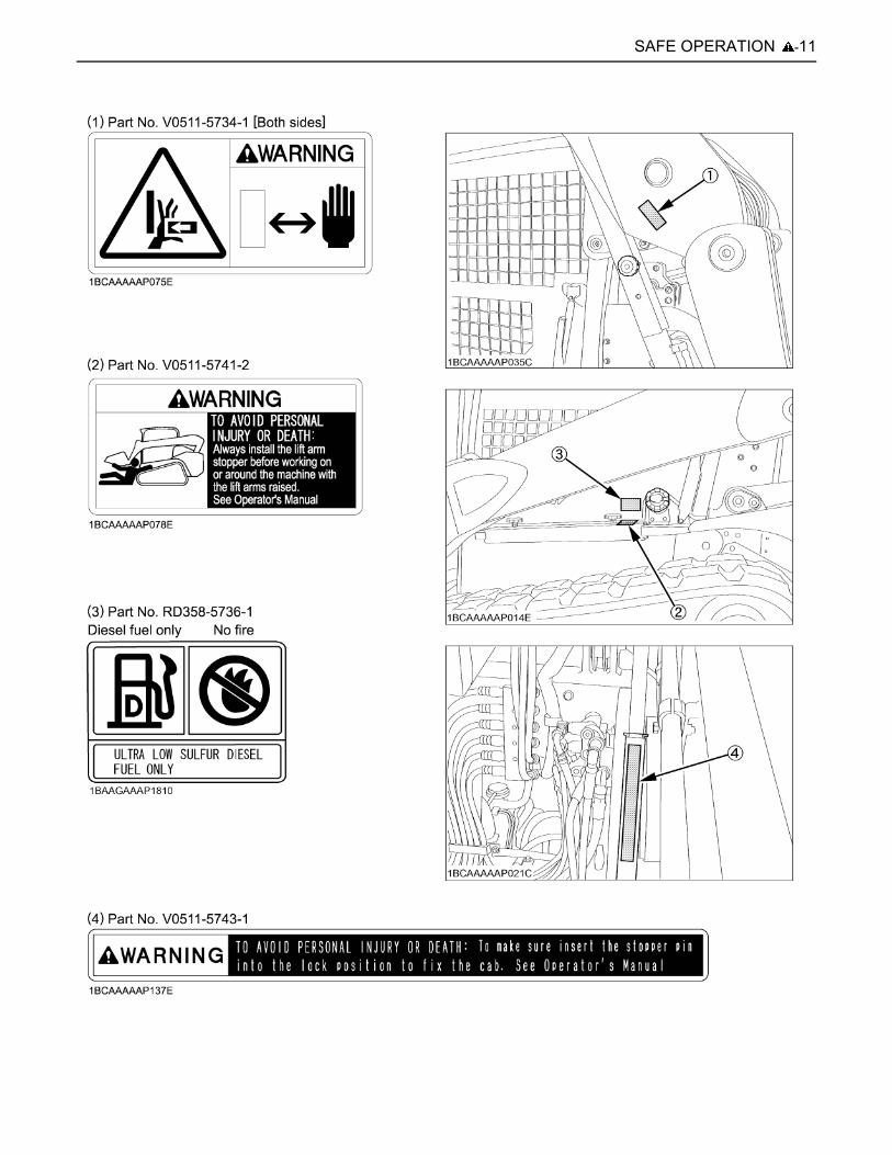
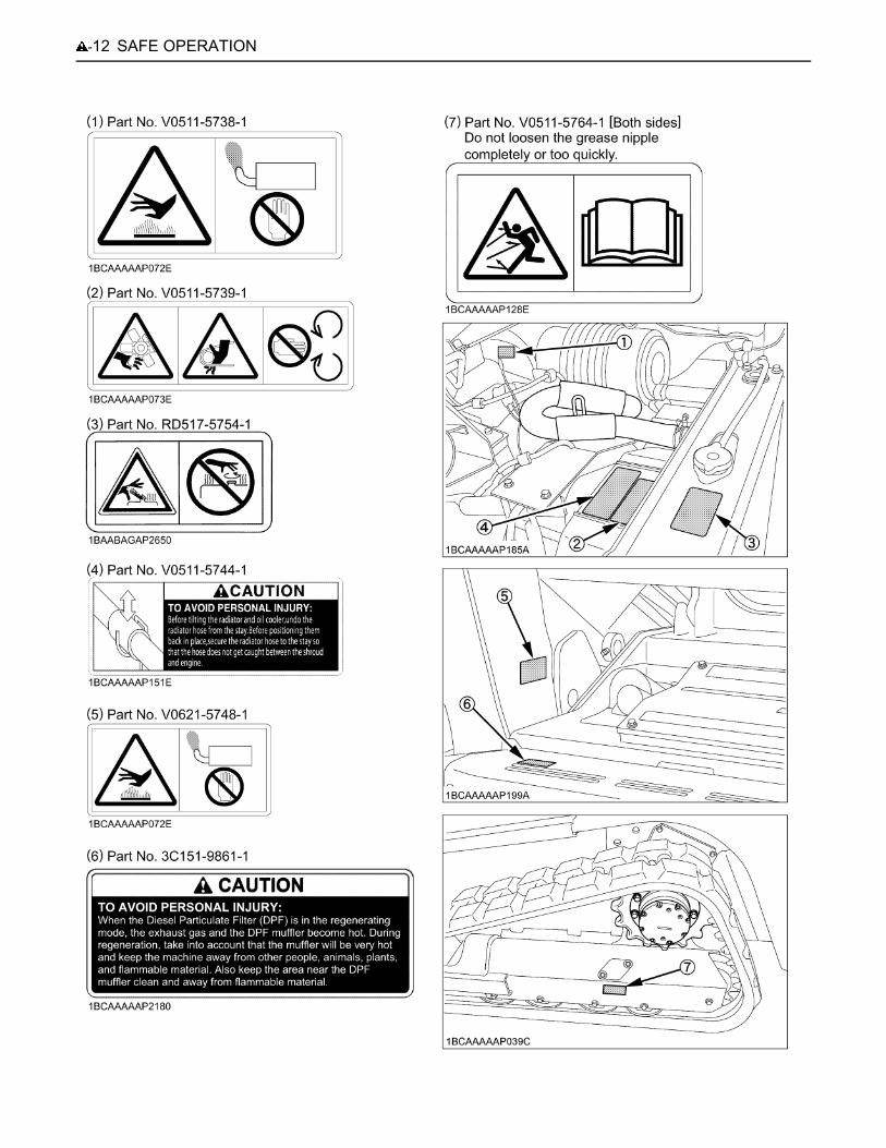
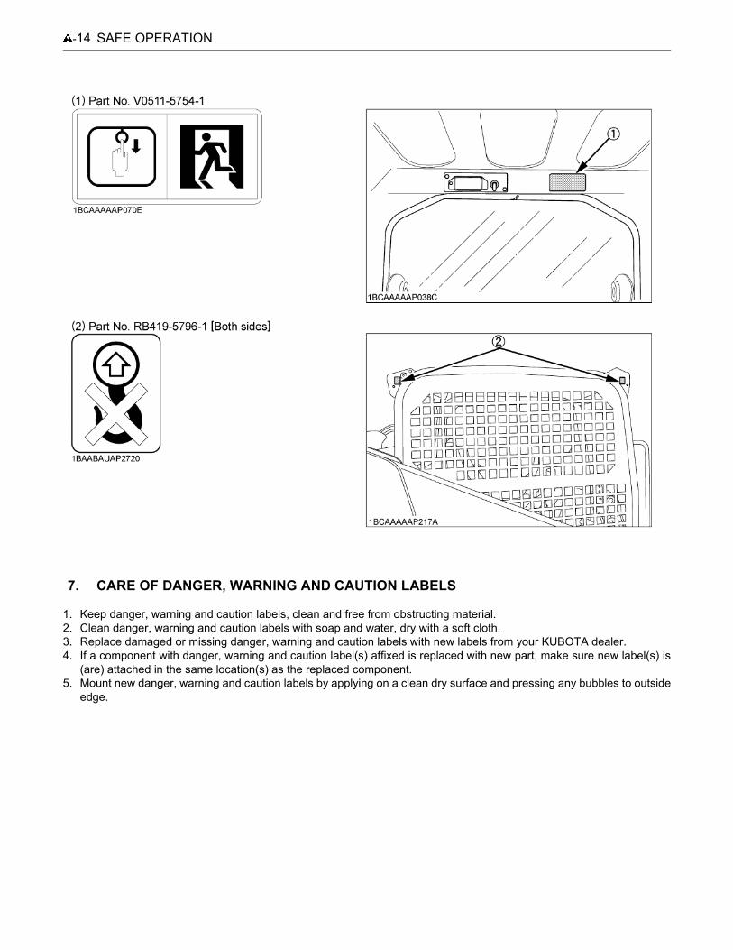
6. DANGER, WARNING AND CAUTION LABELS
-11SAFE OPERATION
SAFE OPERATION-12

-13SAFE OPERATION
SAFE OPERATION-14
1. Keep danger, warning and caution labels, clean and free from obstructing material.2. Clean danger, warning and caution labels with soap and water, dry with a soft cloth. 3. Replace damaged or missing danger, warning and caution labels with new labels from your KUBOTA dealer.4. If a component with danger, warning and caution label(s) affixed is replaced with new part, make sure new label(s) is
(are) attached in the same location(s) as the replaced component.5. Mount new danger, warning and caution labels by applying on a clean dry surface and pressing any bubbles to outside
edge.
7. CARE OF DANGER, WARNING AND CAUTION LABELS
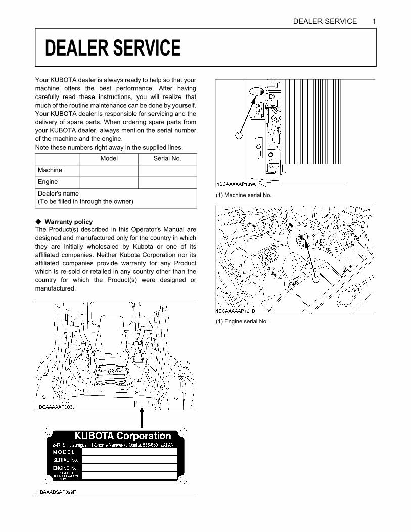
1DEALER SERVICE
DEALER SERVICE
Your KUBOTA dealer is always ready to help so that yourmachine offers the best performance. After havingcarefully read these instructions, you will realize thatmuch of the routine maintenance can be done by yourself.Your KUBOTA dealer is responsible for servicing and thedelivery of spare parts. When ordering spare parts fromyour KUBOTA dealer, always mention the serial numberof the machine and the engine.Note these numbers right away in the supplied lines.C Warranty policyThe Product(s) described in this Operator's Manual aredesigned and manufactured only for the country in whichthey are initially wholesaled by Kubota or one of itsaffiliated companies. Neither Kubota Corporation nor itsaffiliated companies provide warranty for any Productwhich is re-sold or retailed in any country other than thecountry for which the Product(s) were designed ormanufactured.
Model Serial No.
Machine
Engine
Dealer's name(To be filled in through the owner)
(1) Machine serial No.
(1) Engine serial No.
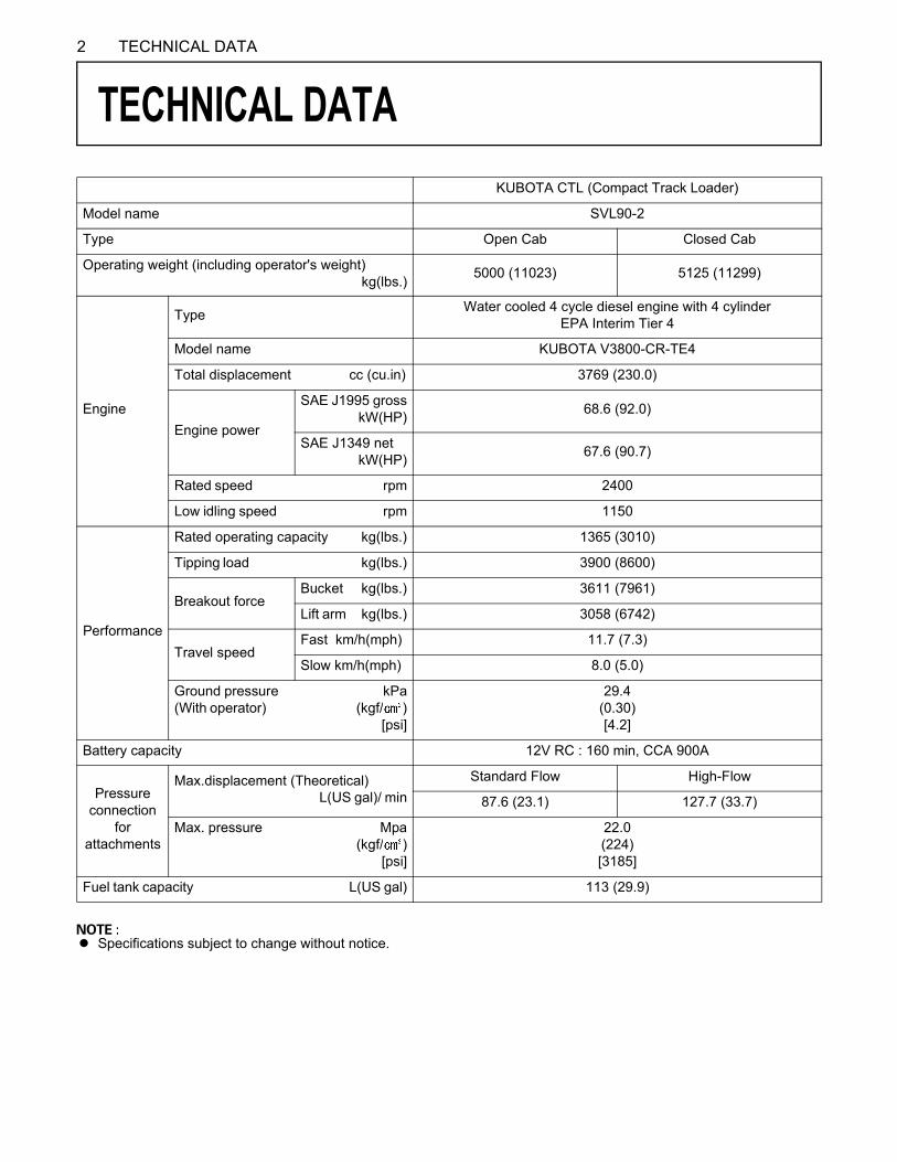
2 TECHNICAL DATA
TECHNICAL DATA
A Specifications subject to change without notice.
KUBOTA CTL (Compact Track Loader)
Model name SVL90-2
Type Open Cab Closed Cab
Operating weight (including operator's weight) kg(lbs.) 5000 (11023) 5125 (11299)
Engine
Type Water cooled 4 cycle diesel engine with 4 cylinderEPA Interim Tier 4
Model name KUBOTA V3800-CR-TE4
Total displacement cc (cu.in) 3769 (230.0)
Engine power
SAE J1995 gross kW(HP) 68.6 (92.0)
SAE J1349 net kW(HP) 67.6 (90.7)
Rated speed rpm 2400
Low idling speed rpm 1150
Performance
Rated operating capacity kg(lbs.) 1365 (3010)
Tipping load kg(lbs.) 3900 (8600)
Breakout forceBucket kg(lbs.) 3611 (7961)
Lift arm kg(lbs.) 3058 (6742)
Travel speedFast km/h(mph) 11.7 (7.3)
Slow km/h(mph) 8.0 (5.0)
Ground pressure kPa(With operator) (kgf/ ) [psi]
29.4(0.30)[4.2]
Battery capacity 12V RC : 160 min, CCA 900A
Pressureconnection
forattachments
Max.displacement (Theoretical) L(US gal)/ min
Standard Flow High-Flow
87.6 (23.1) 127.7 (33.7)
Max. pressure Mpa (kgf/ ) [psi]
22.0(224)[3185]
Fuel tank capacity L(US gal) 113 (29.9)
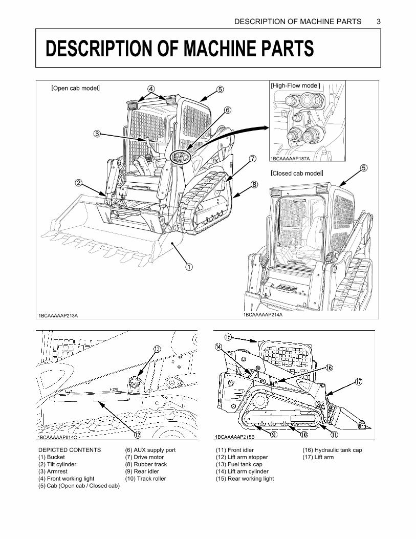
3DESCRIPTION OF MACHINE PARTS
DESCRIPTION OF MACHINE PARTS
DEPICTED CONTENTS(1) Bucket(2) Tilt cylinder(3) Armrest(4) Front working light(5) Cab (Open cab / Closed cab)
(6) AUX supply port(7) Drive motor(8) Rubber track(9) Rear idler(10) Track roller
(11) Front idler(12) Lift arm stopper(13) Fuel tank cap(14) Lift arm cylinder(15) Rear working light
(16) Hydraulic tank cap(17) Lift arm

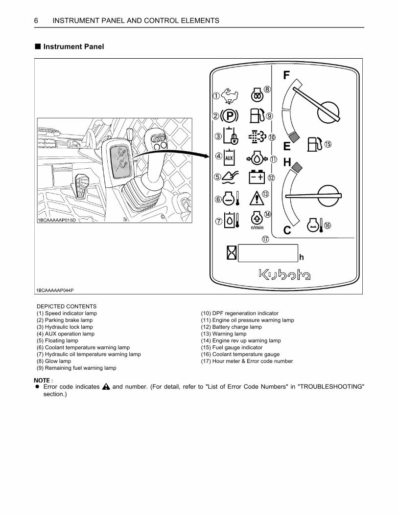
4 INSTRUMENT PANEL AND CONTROL ELEMENTS
INSTRUMENT PANEL AND CONTROL ELEMENTS
B SwitchDEPICTED CONTENTS(1) Horn Switch(2) AUX electrical control switch (Right)(3) AUX electrical control switch (Left)(4) Travel speed switch(5) AUX port variable switch(6) AUX hold switch (Left)(7) AUX hold switch (Right)(8) Float Switch(9) Hydraulic quick-hitch switch (Hydraulic quick-hitch model only)(10) Starter switch(11) Hydraulic unlock switch(12) Parking brake switch(13) AUX port switch(14) Working light switch(15) Wiper / washer switch (Closed cab model)(16) Inhibit Switch

5INSTRUMENT PANEL AND CONTROL ELEMENTS
B Control Pedals, Levers and Electrical Outlet
DEPICTED CONTENTS(1) Left control (traveling) lever(2) Right control (front operating) lever(3) Armrest(4) Seat(5) Accelerator lever(6) Accelerator pedal(7) Electrical outlet
6 INSTRUMENT PANEL AND CONTROL ELEMENTS
B Instrument Panel
A Error code indicates and number. (For detail, refer to "List of Error Code Numbers" in "TROUBLESHOOTING"section.)
DEPICTED CONTENTS(1) Speed indicator lamp(2) Parking brake lamp(3) Hydraulic lock lamp(4) AUX operation lamp(5) Floating lamp(6) Coolant temperature warning lamp(7) Hydraulic oil temperature warning lamp(8) Glow lamp(9) Remaining fuel warning lamp
(10) DPF regeneration indicator(11) Engine oil pressure warning lamp(12) Battery charge lamp(13) Warning lamp(14) Engine rev up warning lamp(15) Fuel gauge indicator(16) Coolant temperature gauge(17) Hour meter & Error code number
7CHECKS BEFORE START
CHECKS BEFORE START
DAILY CHECKSIn order to avoid damage, it is important to check thecondition of the machine before starting.To avoid personal injury:A Do maintenance work on the machine only on
level ground with the engine off and armrest inthe "Raised" position.
ChecksA Go around the machine and check for visual damage
and wear.A Check coolant level. (See "DAILY CHECKS" in
"MAINTENANCE" section.)A Check fuel level.A Check engine oil level.A Check hydraulic fluid level.A Check dust indicator of air cleaner. (See "DAILY
CHECKS" in "MAINTENANCE" section).A Check all control lamps, indicators and hour meter.A Check the light system. A Check the seat belt and the ROPS/FOPS safety
device. A Check Diesel Particulate Filter (DPF) mufflerA Check the condition of the safety and warning labels.
(See "DANGER, WARNING AND CAUTION LABELS"in "SAFE OPERATION" section.)
CHECKING THE SWITCHESBHydraulic Unlock SwitchThe hydraulic unlock switch enables the hydraulic system.The switch is intended to get the hydraulic system(travelling and attachments) ready for use, but does nothave the locking function.To unlock the hydraulic system, the followingrequirements are needed: (1) The engine is running. (2) The armrests are down. (3) The operator is seated on the operator's seat.When the hydraulic system has been unlocked, thehydraulic lock lamp on the instrument panel disappears.If any of the above conditions is not met, the hydraulicsystem stays locked.
BOPC SwitchThis switch is used to detect the operator sitting on theseat and to signal the hydraulic system that it can belocked and unlocked.When the operator sits on the seat, the OPC switch is ON,the hydraulic system can be unlocked.When the hydraulic system is unlocked and the operatorleaves the seat for up to 3 seconds, the OPC switch turnsoff. Now the hydraulic system is locked.
(1) Hydraulic unlock switch
CHECKS BEFORE START8
BParking Brake Switch
To avoid personal injury or death:A When dismounting the machine or when
servicing or hauling, be sure to apply theparking brake.
The parking brake is to be used when parking themachine.1. When the parking brake switch is pressed on " "
marked side (the right side), the parking brake isapplied and the " " mark on the instrument panelappears.
2. When the switch is pressed on the left side, theparking brake is released and the " " mark on theinstrument panel lights off.
A Suppose that the parking brake switch is ON (" "marked side depressed). Even if the hydraulic systemgets unlocked, the travel system remains out ofservice and the brakes are still applied.When the hydraulic system has been locked, the travelsystem gets locked too, and the brakes can get on.
BAUX Port SwitchThis switch is used to enable the AUX port.Press the switch once, and the AUX port is unlocked andthe " " mark on the instrument panel lights up. Bypressing the switch again, the AUX port now gets locked.The AUX port switch can be used only when the AUX portvariable switch on the right control lever is in the neutralposition.
BInhibit Diesel Particulate Filter (DPF) Regeneration Switch
Inhibit Diesel Particulate Filter (DPF) regeneration switch(hereinafter called inhibit switch) disables the Auto DPFregeneration cycle. Activate this switch to turn "off" AutoDPF Regeneration when working around people, animals,plants, and flammable materials. Certain work conditionsmay require the Auto DPF regeneration cycle to bedisabled. Depress the switch once to turn off Automaticmode. Depress the switch once again to return fromdisable to Automatic mode.
(1) Parking brake switch
(1) AUX port switch
(1) Inhibit Switch
9CHECKS BEFORE START
BAUX Port Switch [High-Flow model only]
[High-Flow model only]To avoid personal injury:A Be careful not to use any High-Flow-
incompatible attachment in the High-Flowmode. Otherwise the attachment may bedamaged.
This switch is used to enable the AUX port and also toenable the High-Flow mode.
C Engaging and Disengaging the AUX HydraulicLow-Flow Mode System(1) To turn ON the AUX Hydraulic Low-Flow port,
press the " " side of the AUX port switch onetime. On the instrument panel, the " "symbol willappear.
(2) To turn OFF the AUX Hydraulic Low-Flow port,press the " " side of the AUX port switch again todeactivate.
C Engaging the AUX Hydraulic High-Flow ModeSystem(1) Make sure the High-Flow attachment can be
properly used in the High-Flow mode of thismachine.
(2) To turn ON the AUX Hydraulic High-Flow port,press the " " side of the AUX port switch thenpress the " " side of the switch and hold the " "side of the switch for at least 3 seconds.
(3) After holding the " " side of the AUX port switchfor at least 3 seconds, verify the " " symbolblinks on the instrument panel, then release the" " side of the switch. The machine's AUXhydraulic system is now activated.
A If you hold down the " " side of the AUX port switchlonger than 6 seconds, the " " lamp on the instrumentpanel will not blink and AUX hydraulic flow will returnto Low-Flow mode.The AUX hydraulic High-Flow mode is only activewhen the " " symbol blinks on the instrument panel.
C Disengaging the AUX Hydraulic High-Flow modesystem(1) To turn off the AUX High-Flow mode port, press
the " " side of the AUX port switch.(2) To return to the AUX Low-Flow mode port press
the " " side of the AUX port switch
C Troubleshooting AUX Hydraulic High-Flow mode:If the above steps did not active AUX Hydraulic High-Flowmode, press the " " side of the AUX port switch to clearand turn off the system. Then follow the steps above inthis manual to active the appropriate AUX hydraulicmode.
BWorking Light SwitchThis switch is operative with the starter key in the ONposition.The switch has 3 positions. When positioned on your side,the lights stay off. Move the switch to the first position toturn on the front working light, and to the second positionto turn on both the front working lights and rear workinglights.
(1) AUX port switch [High-Flow model only]
(1) Working light switch

CHECKS BEFORE START10
C Night operation
To avoid personal injury: A Visibility is reduced in darkness, therefore, in
the event, the working light alone does notprovide sufficient visibility. Prepare additionalstationary artificial lighting, observe all safetyrules and any special regulations for nightwork.
BInterior Lamp SwitchThe interior lamp is operative even when the starter key isin the "STOP" position.
BTravel Speed SwitchTravel speed will increase when this switch is presseddown.Switching the dual travel speed:1. Press the travel speed switch. The buzzer beeps twice
and the travel speed changes from low to high speed.The symbol lights up.
2. Press the travel speed switch again, and the buzzerbeeps once and the travel speed changes from high tolow speed. The symbol goes out.
A When activating the travel speed switch, it must bepressed completely. (The switch is operative onlywhen the travel system is unlocked)
A Each time the travel speed switch is pressed, thetravel speed is switched between high and low speed.
(1) Interior lamp switch(2) Interior lamp
(1) Travel speed switch(2) Speed indicator light
11CHECKS BEFORE START
BHorn SwitchEven when the starter key is in "STOP" position, the hornwill be beeped by pressing the horn switch.
BAUX Port Variable SwitchWith the AUX port unlocked, the hydraulic oil flow ratevaries depending on the tilt angle of the switch.
Right-hand control: The flow rate through the right-hand port (male) varies.Left-hand control: The flow rate through the left-hand port (female) varies.
BAUX Hold SwitchPress the right or left hold switch to maximize the flowrate.
BAUX Electrical Control Switch (Option)With the AUX port switch unlocked, this switch serves tofeed electrical power to attachments.
A The 14-pin coupler (option) is required for thisfunction.
(1) Horn switch
(1) AUX port variable switch
(1) AUX hold switch (Right)(2) AUX hold switch (Left)
(1) AUX electrical control switch (Right)(2) AUX electrical control switch (Left)
CHECKS BEFORE START12
BFloat Switch
To avoid personal injury or death:A Make sure the bucket is lowered to the ground
before putting the lift arms in the "FLOAT"position. Putting the lift arms in the "FLOAT"position while they are off the ground willcause the bucket and lift arms to fall and isextremely dangerous.
A Do not drive the machine forward with the liftarms in the "FLOAT" position.
C Entering the float modeWhile moving down the arm (tilting the right control leverforward), press the float switch on the right control leverand release it no later than 1 second. The float mode isthen turned on.While in the float mode, the " " mark on the instrumentpanel stays on.
C Exiting the float modeWhile the machine is in the float mode,
(1) Press the float switch on the right control lever.(2) Or move up the arm (pulling the right control lever
backward).
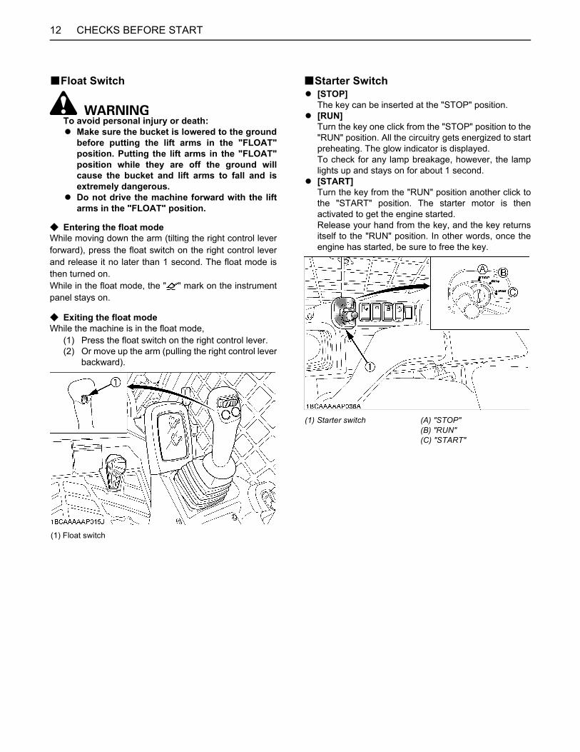
BStarter SwitchA [STOP]
The key can be inserted at the "STOP" position.A [RUN]
Turn the key one click from the "STOP" position to the"RUN" position. All the circuitry gets energized to startpreheating. The glow indicator is displayed.To check for any lamp breakage, however, the lamplights up and stays on for about 1 second.
A [START]Turn the key from the "RUN" position another click tothe "START" position. The starter motor is thenactivated to get the engine started.Release your hand from the key, and the key returnsitself to the "RUN" position. In other words, once theengine has started, be sure to free the key.
(1) Float switch
(1) Starter switch (A) "STOP"(B) "RUN"(C) "START"
13CHECKS BEFORE START
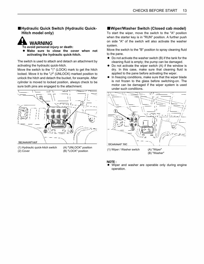
BHydraulic Quick Switch (Hydraulic Quick-Hitch model only)
To avoid personal injury or death:A Make sure to close the cover when not
activating the hydraulic quick-hitch.
The switch is used to attach and detach an attachment byactivating the hydraulic quick-hitch.Move the switch to the " " (LOCK) mark to get the hitchlocked. Move it to the " " (UNLOCK) marked position tounlock the hitch and detach the bucket, for example. Aftercylinder is moved to locked position, always check to besure both pins are engaged to the attachment.
BWiper/Washer Switch (Closed cab model)To start the wiper, move the switch to the "A" positionwhen the starter key is in "RUN" position. A further pushon side "A" of the switch will also activate the washersystem.Move the switch to the "B" position to spray cleaning fluidto the pane.A Do not activate the washer switch (B) if the tank for the
cleaning fluid is empty; the pump can be damaged.A Do not activate the wiper switch (A) if the window is
dry. In this case, make sure that cleaning fluid isapplied to the pane before activating the wiper.
A In freezing conditions, make sure that the wiper bladeis not frozen to the glass before switching-on. Themotor can be damaged if the wiper system is usedunder such conditions.
A Wiper and washer are operable only during engineoperation.
(1) Hydraulic quick-hitch switch(2) Cover
(A) "UNLOCK" position(B) "LOCK" position (1) Wiper / Washer switch (A) "Wiper"
(B) "Washer"
CHECKS BEFORE START14
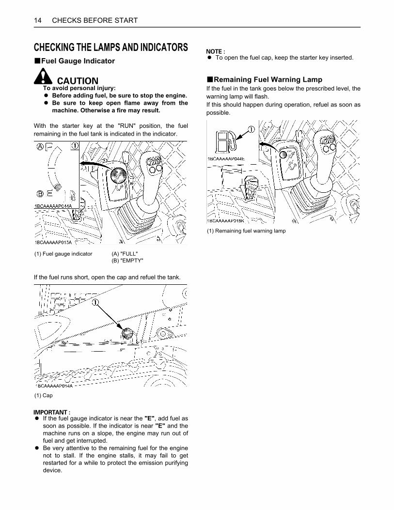
CHECKING THE LAMPS AND INDICATORSBFuel Gauge Indicator
To avoid personal injury:A Before adding fuel, be sure to stop the engine.A Be sure to keep open flame away from the
machine. Otherwise a fire may result.
With the starter key at the "RUN" position, the fuelremaining in the fuel tank is indicated in the indicator.
If the fuel runs short, open the cap and refuel the tank.
A If the fuel gauge indicator is near the "E", add fuel assoon as possible. If the indicator is near "E" and themachine runs on a slope, the engine may run out offuel and get interrupted.
A Be very attentive to the remaining fuel for the enginenot to stall. If the engine stalls, it may fail to getrestarted for a while to protect the emission purifyingdevice.
A To open the fuel cap, keep the starter key inserted.
BRemaining Fuel Warning LampIf the fuel in the tank goes below the prescribed level, thewarning lamp will flash.If this should happen during operation, refuel as soon aspossible.
(1) Fuel gauge indicator (A) "FULL"(B) "EMPTY"
(1) Cap
(1) Remaining fuel warning lamp
15CHECKS BEFORE START
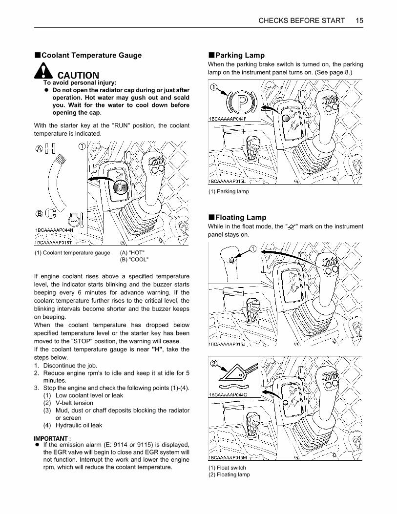
BCoolant Temperature Gauge
To avoid personal injury:A Do not open the radiator cap during or just after
operation. Hot water may gush out and scaldyou. Wait for the water to cool down beforeopening the cap.
With the starter key at the "RUN" position, the coolanttemperature is indicated.
If engine coolant rises above a specified temperaturelevel, the indicator starts blinking and the buzzer startsbeeping every 6 minutes for advance warning. If thecoolant temperature further rises to the critical level, theblinking intervals become shorter and the buzzer keepson beeping.When the coolant temperature has dropped belowspecified temperature level or the starter key has beenmoved to the "STOP" position, the warning will cease.If the coolant temperature gauge is near "H", take thesteps below.1. Discontinue the job.2. Reduce engine rpm's to idle and keep it at idle for 5
minutes.3. Stop the engine and check the following points (1)-(4).
(1) Low coolant level or leak(2) V-belt tension(3) Mud, dust or chaff deposits blocking the radiator
or screen(4) Hydraulic oil leak
A If the emission alarm (E: 9114 or 9115) is displayed,the EGR valve will begin to close and EGR system willnot function. Interrupt the work and lower the enginerpm, which will reduce the coolant temperature.
BParking LampWhen the parking brake switch is turned on, the parkinglamp on the instrument panel turns on. (See page 8.)
BFloating LampWhile in the float mode, the " " mark on the instrumentpanel stays on.
(1) Coolant temperature gauge (A) "HOT"(B) "COOL"
(1) Parking lamp
(1) Float switch(2) Floating lamp
CHECKS BEFORE START16
BWarning LampThe warning lamp is used to indicate broken wire, short-circuit and other problems.The lamp lights up to warn you of a detection of broken orshort-circuited hydraulic lock/unlock solenoid, AUX portvariable switch and other elements.
A If the warning lamp lights up, consult your localKUBOTA dealer immediately.
BGlow LampThe glow lamp is displayed when the starter key is turnedto the "RUN" position but the engine requires preheating.Wait until the indicator goes out, and then start the engine.
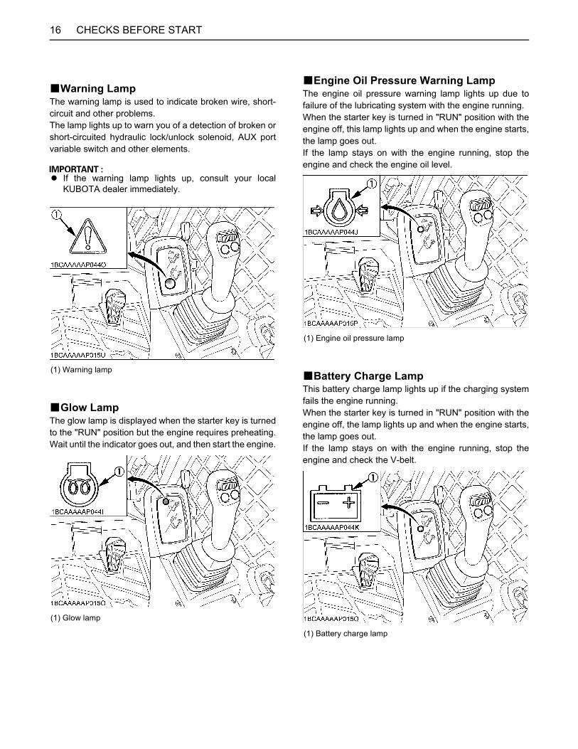
BEngine Oil Pressure Warning LampThe engine oil pressure warning lamp lights up due tofailure of the lubricating system with the engine running.When the starter key is turned in "RUN" position with theengine off, this lamp lights up and when the engine starts,the lamp goes out.If the lamp stays on with the engine running, stop theengine and check the engine oil level.
BBattery Charge LampThis battery charge lamp lights up if the charging systemfails the engine running.When the starter key is turned in "RUN" position with theengine off, the lamp lights up and when the engine starts,the lamp goes out.If the lamp stays on with the engine running, stop theengine and check the V-belt.
(1) Warning lamp
(1) Glow lamp
(1) Engine oil pressure lamp
(1) Battery charge lamp

17CHECKS BEFORE START
BHydraulic Oil Temperature GaugeThe lamp starts blinking and the buzzer starts beeping ifthe hydraulic oil temperature has reached a specifiedlevel.When the oil temperature has dropped below thespecified level or the starter key is turned off, the warningwill cease.Stop the engine and check for an unspecified level in thehydraulic oil tank and for a hydraulic oil leak.
BHour-MeterIndicates the total operating hours of the machine.
How the indicator worksA The meter advances one hour after an hour of
operation regardless of the engine rpm.
BDiesel Particulate Filter (DPF) regeneration indicator
As PM (Particulate Matter) build up inside the DPF, theDPF regeneration cycle starts automatically to burn awayPM. During DPF regeneration, this lamp lights up andstays on and the beep tone keeps sounding to warn theoperator.
BEngine rev up warning lampIf the engine rpm is too low to start regeneration, the DPFregeneration indicator lights up and starts blinking. Insuch case, rev up the engine until this lamp goes out, theregeneration will automatically start.
(1) Hydraulic oil temperature warning lamp
(1) Hour-meter
(1) DPF regeneration indicator
(1) Engine rev up warning lamp

CHECKS BEFORE START18
EXAUST AFTERTREATMENT DEVICESBCatalyst-containing Diesel Particulate
Filter (DPF) deviceThis after-treatment device has two functions: reducingcertain emissions, like hydrocarbon (HC) and carbonmonoxide (CO), to innoxious carbon diode and water, andtrapping and elimination PM (Particulate Matter) throughthe filter at the same time.Following EPA regulations, it is necessary to service theDPF, such as renewing or cleaning the filter at regularintervals.Be sure to carefully read this Operator’s Manual beforeusing the machine.The machine owner and operator areresponsible for handling this device correctly to protectthe environment and to prevent damage to the DPF, andcomply with Federal and state regulations.
C Handling instructionsA FuelBe sure to use ULTRA LOW SULFUR FUEL (S15).Use of other diesel fuel other than this may adverselyaffect the engine and the emission control device and maydamage them. A Engine oilUse DPF-compatible engine oil (CJ-4). Any unspecifiedoil may damage the DPF earlier than expected and lowerfuel economy.
A If you use different fuel or engine oil, the cleaninginterval of the DPF (3000 hours) can’t be secured andthe DPF will be clogged for a shorter time thanexpected.
C Prohibited unnecessary idlingGenerally speaking, the lower the engine rpm is, the lowerthe exhaust gas temperature is. It is more difficult to burnPM (Particulate Matter) in the DPF. With this in mind, donot keep the engine idling unnecessarily.If you leave the machine with the engine running, toprotect the DPF the engine can stop automatically.
C DPF regeneration systemOn the Kubota CTL, the ECU prompts DPF-regenerationcycle. When starting the engine, Auto Regeneration Modeis set by default. When all the conditions are met,regeneration automatically starts, unless the inhibit switchis engaged.
BRegeneration of Diesel Particulate Filter (DPF)
To avoid personal injury:A When the DPF is in the regenerating mode, the
exhaust gas and the DPF muffler become hot.During the regeneration, take into account thatthe muffler will be very hot and keep themachine away from other people, animals,plants, and flammable material. Also keep thearea near the DPF muffler clean and away fromflammable material.
A Do not leave the machine during DPFregeneration.
The DPF level of PM during operation is indicated byindicator symbol and buzzer.
A During DPF regeneration cycle keep clear of thesurrounding environment in mind. Do not allow theambient temperature to rise excessively due to heatfrom the regeneration. If such occurs, activate theinhibit switch.
A The DPF regeneration cycle only starts in the followingconditions. If any of the conditions are not met, theDPF regeneration cycle may be interrupted.(1) Coolant temperature above 65 C(2) DPF temperature above 250 C(3) Engine rpm above 1200 rpm
A The regeneration usually takes about 15-20 minutes.It depends, however, on the outside air temperature,exhaust gas temperature and filter PM level.
A Do not attempt to interrupt the DPF regeneration cycleunnecessarily.
(1) DPF regeneration indicator(2) Engine rev up warning lamp
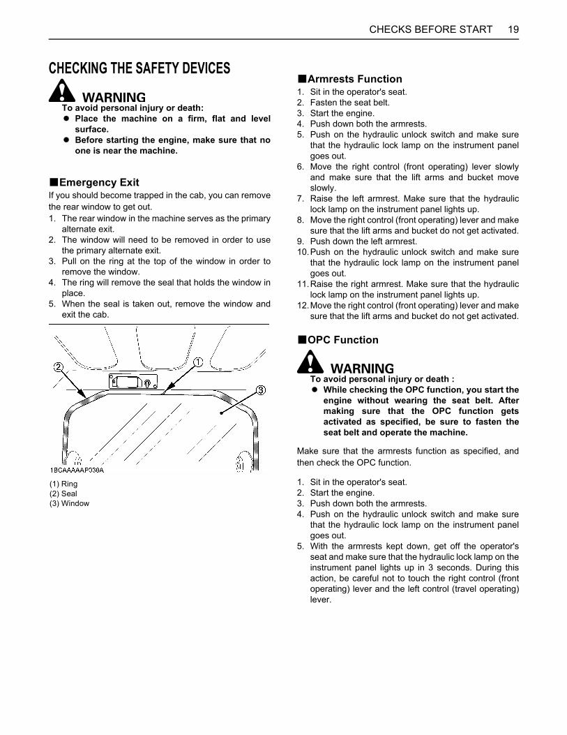
19CHECKS BEFORE START
CHECKING THE SAFETY DEVICES
To avoid personal injury or death:A Place the machine on a firm, flat and level
surface.A Before starting the engine, make sure that no
one is near the machine.
BEmergency ExitIf you should become trapped in the cab, you can removethe rear window to get out.1. The rear window in the machine serves as the primary
alternate exit.2. The window will need to be removed in order to use
the primary alternate exit.3. Pull on the ring at the top of the window in order to
remove the window.4. The ring will remove the seal that holds the window in
place.5. When the seal is taken out, remove the window and
exit the cab.
BArmrests Function1. Sit in the operator's seat.2. Fasten the seat belt.3. Start the engine.4. Push down both the armrests.5. Push on the hydraulic unlock switch and make sure
that the hydraulic lock lamp on the instrument panelgoes out.
6. Move the right control (front operating) lever slowlyand make sure that the lift arms and bucket moveslowly.
7. Raise the left armrest. Make sure that the hydrauliclock lamp on the instrument panel lights up.
8. Move the right control (front operating) lever and makesure that the lift arms and bucket do not get activated.
9. Push down the left armrest.10.Push on the hydraulic unlock switch and make sure
that the hydraulic lock lamp on the instrument panelgoes out.
11.Raise the right armrest. Make sure that the hydrauliclock lamp on the instrument panel lights up.
12.Move the right control (front operating) lever and makesure that the lift arms and bucket do not get activated.
BOPC Function
To avoid personal injury or death :A While checking the OPC function, you start the
engine without wearing the seat belt. Aftermaking sure that the OPC function getsactivated as specified, be sure to fasten theseat belt and operate the machine.
Make sure that the armrests function as specified, andthen check the OPC function.
1. Sit in the operator's seat.2. Start the engine.3. Push down both the armrests.4. Push on the hydraulic unlock switch and make sure
that the hydraulic lock lamp on the instrument panelgoes out.
5. With the armrests kept down, get off the operator'sseat and make sure that the hydraulic lock lamp on theinstrument panel lights up in 3 seconds. During thisaction, be careful not to touch the right control (frontoperating) lever and the left control (travel operating)lever.
(1) Ring(2) Seal(3) Window
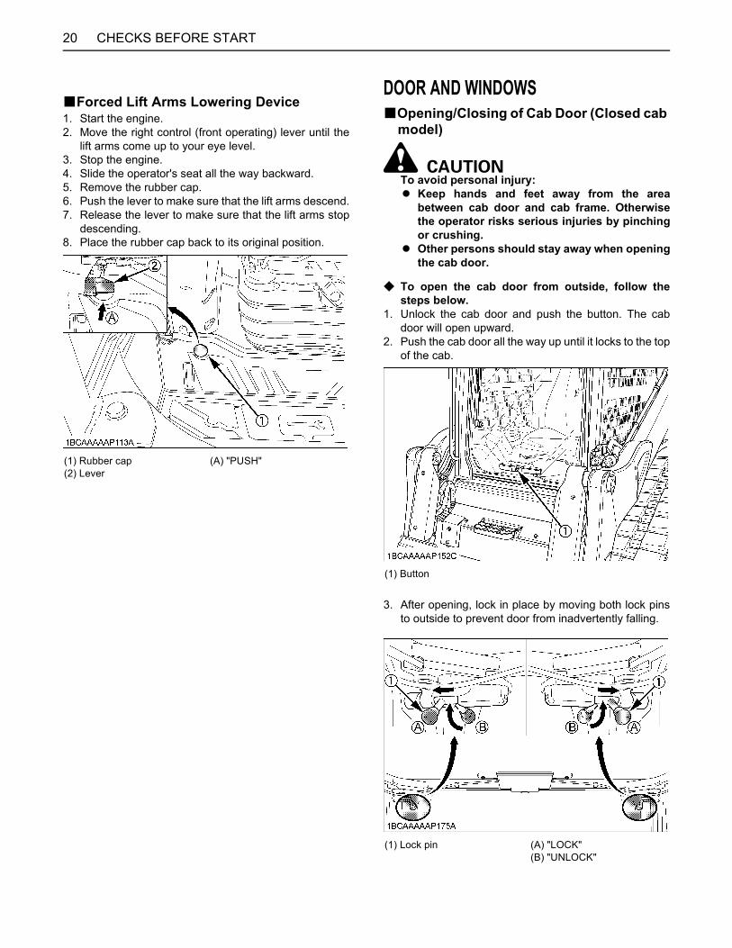
CHECKS BEFORE START20
BForced Lift Arms Lowering Device1. Start the engine.2. Move the right control (front operating) lever until the
lift arms come up to your eye level. 3. Stop the engine.4. Slide the operator's seat all the way backward.5. Remove the rubber cap. 6. Push the lever to make sure that the lift arms descend.7. Release the lever to make sure that the lift arms stop
descending.8. Place the rubber cap back to its original position.
DOOR AND WINDOWSBOpening/Closing of Cab Door (Closed cab
model)
To avoid personal injury:A Keep hands and feet away from the area
between cab door and cab frame. Otherwisethe operator risks serious injuries by pinchingor crushing.
A Other persons should stay away when openingthe cab door.
C To open the cab door from outside, follow thesteps below.
1. Unlock the cab door and push the button. The cabdoor will open upward.
2. Push the cab door all the way up until it locks to the topof the cab.
3. After opening, lock in place by moving both lock pinsto outside to prevent door from inadvertently falling.
(1) Rubber cap(2) Lever
(A) "PUSH"
(1) Button
(1) Lock pin (A) "LOCK"(B) "UNLOCK"
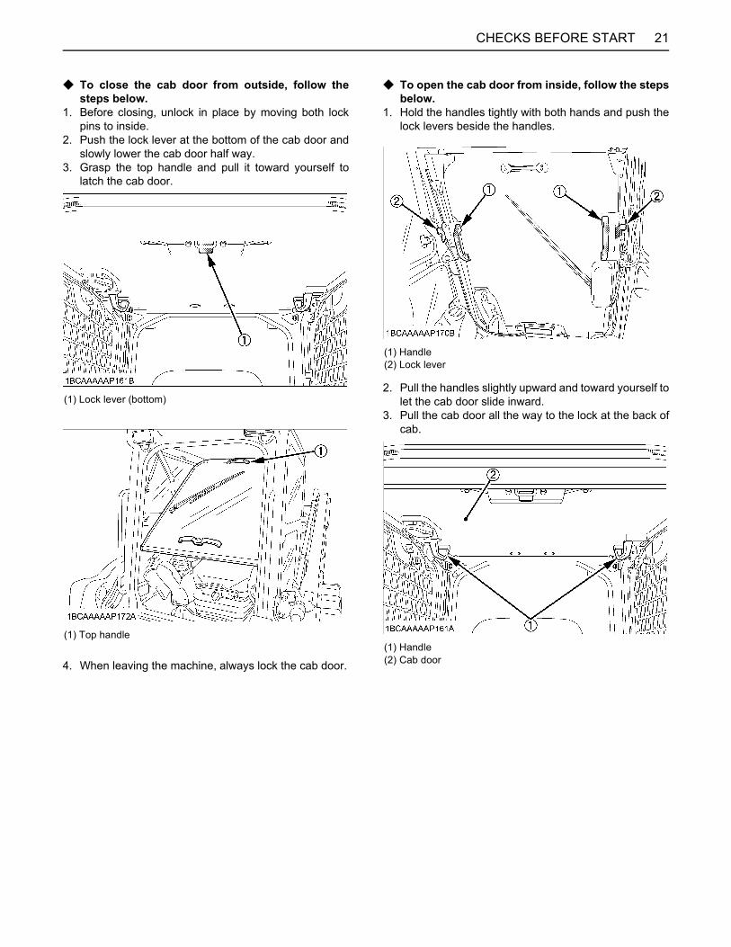
21CHECKS BEFORE START
C To close the cab door from outside, follow thesteps below.
1. Before closing, unlock in place by moving both lockpins to inside.
2. Push the lock lever at the bottom of the cab door andslowly lower the cab door half way.
3. Grasp the top handle and pull it toward yourself tolatch the cab door.
4. When leaving the machine, always lock the cab door.
C To open the cab door from inside, follow the stepsbelow.
1. Hold the handles tightly with both hands and push thelock levers beside the handles.
2. Pull the handles slightly upward and toward yourself tolet the cab door slide inward.
3. Pull the cab door all the way to the lock at the back ofcab.
(1) Lock lever (bottom)
(1) Top handle
(1) Handle(2) Lock lever
(1) Handle (2) Cab door
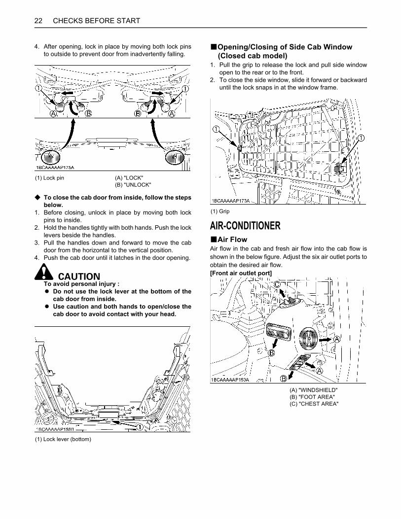
CHECKS BEFORE START22
4. After opening, lock in place by moving both lock pinsto outside to prevent door from inadvertently falling.
C To close the cab door from inside, follow the stepsbelow.
1. Before closing, unlock in place by moving both lockpins to inside.
2. Hold the handles tightly with both hands. Push the locklevers beside the handles.
3. Pull the handles down and forward to move the cabdoor from the horizontal to the vertical position.
4. Push the cab door until it latches in the door opening.
To avoid personal injury :A Do not use the lock lever at the bottom of the
cab door from inside.A Use caution and both hands to open/close the
cab door to avoid contact with your head.
BOpening/Closing of Side Cab Window (Closed cab model)
1. Pull the grip to release the lock and pull side windowopen to the rear or to the front.
2. To close the side window, slide it forward or backwarduntil the lock snaps in at the window frame.
AIR-CONDITIONERBAir FlowAir flow in the cab and fresh air flow into the cab flow isshown in the below figure. Adjust the six air outlet ports toobtain the desired air flow.[Front air outlet port]
(1) Lock pin (A) "LOCK"(B) "UNLOCK"
(1) Lock lever (bottom)
(1) Grip
(A) "WINDSHIELD"(B) "FOOT AREA"(C) "CHEST AREA"
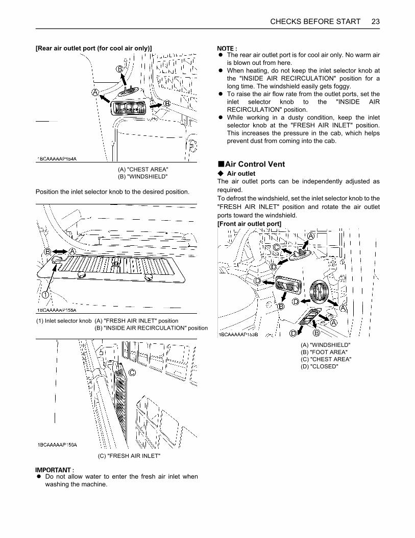
23CHECKS BEFORE START
[Rear air outlet port (for cool air only)]
Position the inlet selector knob to the desired position.
A Do not allow water to enter the fresh air inlet whenwashing the machine.
A The rear air outlet port is for cool air only. No warm airis blown out from here.
A When heating, do not keep the inlet selector knob atthe "INSIDE AIR RECIRCULATION" position for along time. The windshield easily gets foggy.
A To raise the air flow rate from the outlet ports, set theinlet selector knob to the "INSIDE AIRRECIRCULATION" position.
A While working in a dusty condition, keep the inletselector knob at the "FRESH AIR INLET" position.This increases the pressure in the cab, which helpsprevent dust from coming into the cab.
BAir Control VentC Air outletThe air outlet ports can be independently adjusted asrequired.To defrost the windshield, set the inlet selector knob to the"FRESH AIR INLET" position and rotate the air outletports toward the windshield.[Front air outlet port]
(A) "CHEST AREA"(B) "WINDSHIELD"
(1) Inlet selector knob (A) "FRESH AIR INLET" position(B) "INSIDE AIR RECIRCULATION" position
(C) "FRESH AIR INLET"
(A) "WINDSHIELD"(B) "FOOT AREA"(C) "CHEST AREA"(D) "CLOSED"
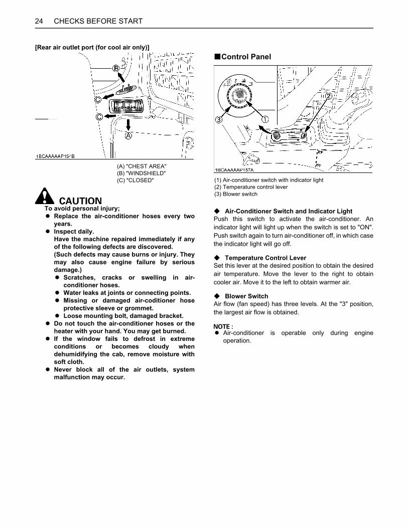
CHECKS BEFORE START24
[Rear air outlet port (for cool air only)]
To avoid personal injury;A Replace the air-conditioner hoses every two
years.A Inspect daily.
Have the machine repaired immediately if anyof the following defects are discovered.(Such defects may cause burns or injury. Theymay also cause engine failure by seriousdamage.)A Scratches, cracks or swelling in air-
conditioner hoses.A Water leaks at joints or connecting points.A Missing or damaged air-coditioner hose
protective sleeve or grommet.A Loose mounting bolt, damaged bracket.
A Do not touch the air-conditioner hoses or theheater with your hand. You may get burned.
A If the window fails to defrost in extremeconditions or becomes cloudy whendehumidifying the cab, remove moisture withsoft cloth.
A Never block all of the air outlets, systemmalfunction may occur.
BControl Panel
C Air-Conditioner Switch and Indicator LightPush this switch to activate the air-conditioner. Anindicator light will light up when the switch is set to "ON".Push switch again to turn air-conditioner off, in which casethe indicator light will go off.
C Temperature Control LeverSet this lever at the desired position to obtain the desiredair temperature. Move the lever to the right to obtaincooler air. Move it to the left to obtain warmer air.
C Blower SwitchAir flow (fan speed) has three levels. At the "3" position,the largest air flow is obtained.
A Air-conditioner is operable only during engineoperation.
(A) "CHEST AREA"(B) "WINDSHIELD"(C) "CLOSED" (1) Air-conditioner switch with indicator light
(2) Temperature control lever(3) Blower switch
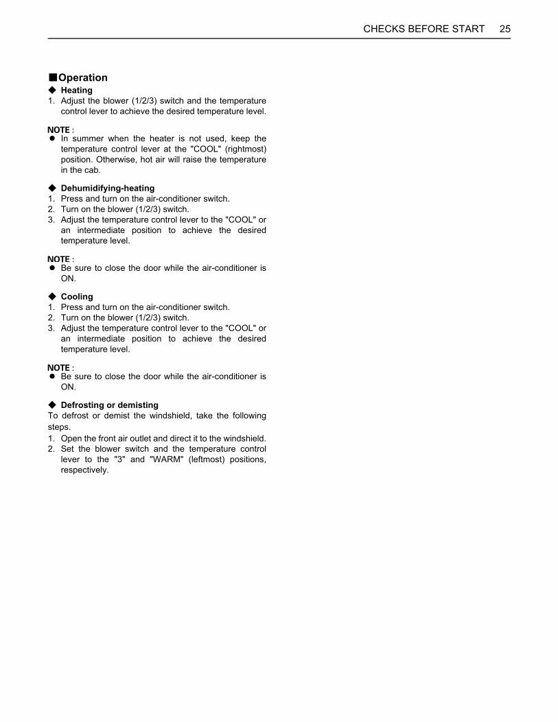
25CHECKS BEFORE START
BOperationC Heating1. Adjust the blower (1/2/3) switch and the temperature
control lever to achieve the desired temperature level.
A In summer when the heater is not used, keep thetemperature control lever at the "COOL" (rightmost)position. Otherwise, hot air will raise the temperaturein the cab.
C Dehumidifying-heating1. Press and turn on the air-conditioner switch.2. Turn on the blower (1/2/3) switch.3. Adjust the temperature control lever to the "COOL" or
an intermediate position to achieve the desiredtemperature level.
A Be sure to close the door while the air-conditioner isON.
C Cooling1. Press and turn on the air-conditioner switch.2. Turn on the blower (1/2/3) switch.3. Adjust the temperature control lever to the "COOL" or
an intermediate position to achieve the desiredtemperature level.
A Be sure to close the door while the air-conditioner isON.
C Defrosting or demistingTo defrost or demist the windshield, take the followingsteps.1. Open the front air outlet and direct it to the windshield.2. Set the blower switch and the temperature control
lever to the "3" and "WARM" (leftmost) positions,respectively.
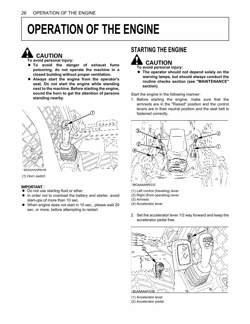
26 OPERATION OF THE ENGINE
OPERATION OF THE ENGINE
To avoid personal injury: A To avoid the danger of exhaust fume
poisoning, do not operate the machine in aclosed building without proper ventilation.
A Always start the engine from the operator'sseat. Do not start the engine while standingnext to the machine. Before starting the engine,sound the horn to get the attention of personsstanding nearby.
A Do not use starting fluid or ether.A In order not to overload the battery and starter, avoid
start-ups of more than 10 sec.A When engine does not start in 10 sec., please wait 20
sec. or more, before attempting to restart.
STARTING THE ENGINE
To avoid personal injury:A The operator should not depend solely on the
warning lamps, but should always conduct theroutine checks section (see "MAINTENANCE"section).
Start the engine in the following manner:1. Before starting the engine, make sure that the
armrests are in the "Raised" position and the controllevers are in their neutral position and the seat belt isfastened correctly.
2. Set the accelerator lever 1/2 way forward and keep theaccelerator pedal free.
(1) Horn switch
(1) Left control (traveling) lever(2) Right (front operating) lever(3) Armrest(4) Accelerator lever
(1) Accelerator lever(2) Accelerator pedal
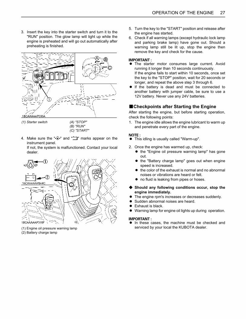
27OPERATION OF THE ENGINE
3. Insert the key into the starter switch and turn it to the"RUN" position. The glow lamp will light up while theengine is preheated and will go out automatically afterpreheating is finished.
4. Make sure the " " and " " marks appear on theinstrument panel. If not, the system is malfunctioned. Contact your localdealer.
5. Turn the key to the "START" position and release afterthe engine has started.
6. Check if all warning lamps (except hydraulic lock lampand parking brake lamp) have gone out. Should awarning lamp still be lit up, stop the engine thenremove the key and check for the cause.
A The starter motor consumes large current. Avoidrunning it longer than 10 seconds continuously.If the engine fails to start within 10 seconds, once setthe key to the "STOP" position, wait for 20 seconds orlonger, and repeat the above step 3 through 6.
A If the battery is dead and must be connected toanother battery with jumper cable, be sure to use a12V battery. Never use any 24V batteries.
BCheckpoints after Starting the EngineAfter starting the engine, but before starting operation,check the following points:1. The engine idle allows the engine lubricant to warm up
and penetrate every part of the engine.
A This idling is usually called "Warm-up".
2. Once the engine has warmed up, check:A the "Engine oil pressure warning lamp" has gone
out.A the "Battery charge lamp" goes out when engine
speed is increased.A the color of the exhaust is normal and no abnormal
noises or vibrations are heard or felt.A no fluid is leaking from pipes or hoses.
C Should any following conditions occur, stop theengine immediately.
A The engine rpm's increases or decreases suddenly. A Sudden abnormal noises are heard.A Exhaust is black.A Warning lamp for engine oil lights up during operation.
A In these cases, the machine must be checked andserviced by your local the KUBOTA dealer.
(1) Starter switch (A) "STOP"(B) "RUN"(C) "START"
(1) Engine oil pressure warning lamp(2) Battery charge lamp

OPERATION OF THE ENGINE28
STARTING THE ENGINE UNDER COLD CONDITIONS
To avoid personal injury:A Make sure that the armrests are in the "Raised"
position during warm up.
Start the engine in the following manner;1. Turn the starter switch to the "RUN" position (glow
position) and hold until the indicator lamp has goneout.
2. Move the starter switch to the "START" position; tocrank and start engine.
3. Release the starter switch after the engine has started;it will automatically return to the "RUN " position.
A Let the engine warm up after start-up for approx. 10minutes under no load conditions. If the hydraulic fluidtemperature is too low, the operations or the functionof the pressure sensors will be affected.Do not operate the machine under full load before theengine has warmed up enough.
STOPPING THE ENGINE
To avoid personal injury or death:A Do not keep the bucket or attachments in the
lifted position, as a person could accidentallytouch the levers and cause serious accidents.
A Place the machine on the flat ground.
1. After slowing the engine to idle, turn the key to "STOP"position.
2. Remove the key.
STARTING WITH AN AUXILIARY BATTERY
To avoid personal injury: A Battery gases can explode.
Do not smoke and keep sparks and flamesaway.
A Do not start the engine with an auxiliary batteryif machine battery is frozen.
A Do not connect the black jumper cable to thenegative (-) terminal of the machine battery.
BObserve Following Guidelines when Starting with an Auxiliary Battery
1. Bring the helping machine with the same batteryvoltage as near as possible to the machine.THE MACHINES MUST NOT COME IN CONTACTWITH EACH OTHER.
2. Bring the levers and pedal of both machines in theneutral position.
3. Wear eye protection and rubber gloves.4. Ensure the vent caps are securely in place (if
equipped).5. Connect the terminal of the red jumper cable with the
plus (+) terminal of the low battery and connect theother end of the cable to the plus (+) terminal of theauxiliary battery.
6. Connect the black negative cable to the minus (-)terminal of the auxiliary battery.
7. Connect the other end of the black cable (coming fromthe auxiliary battery) to the conductive part of themachine frame as far away as possible from the lowbattery.
8. Start the engine of the helping machine and let it runfor a while. Start the machine with the low battery.
9. Disconnect the jumper cables in the reversesequence.
A This machine has a negative (-) ground 12 Volt startingsystem.
A Only use the same voltage when using an auxiliarybattery.
A Using a higher voltage will cause serious damage tothe electrical system. When using an auxiliary battery,only the compatible (same) voltage is permissible.
(1) Low battery(2) Auxiliary battery(3) Jumper cables
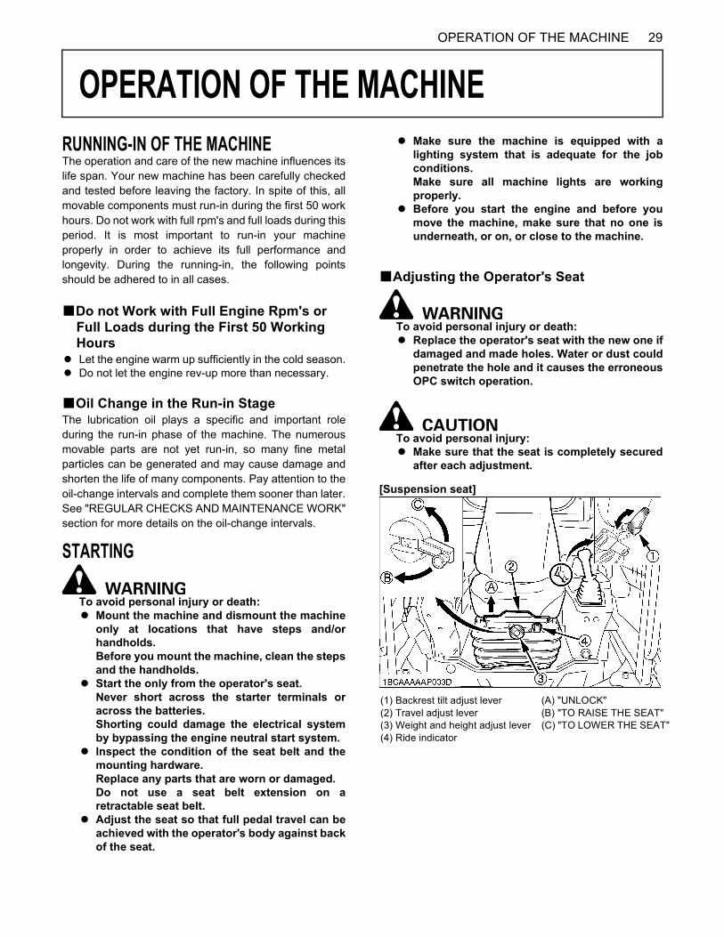
29OPERATION OF THE MACHINE
OPERATION OF THE MACHINE
RUNNING-IN OF THE MACHINEThe operation and care of the new machine influences itslife span. Your new machine has been carefully checkedand tested before leaving the factory. In spite of this, allmovable components must run-in during the first 50 workhours. Do not work with full rpm's and full loads during thisperiod. It is most important to run-in your machineproperly in order to achieve its full performance andlongevity. During the running-in, the following pointsshould be adhered to in all cases.BDo not Work with Full Engine Rpm's or Full Loads during the First 50 Working Hours
A Let the engine warm up sufficiently in the cold season.A Do not let the engine rev-up more than necessary.
BOil Change in the Run-in StageThe lubrication oil plays a specific and important roleduring the run-in phase of the machine. The numerousmovable parts are not yet run-in, so many fine metalparticles can be generated and may cause damage andshorten the life of many components. Pay attention to theoil-change intervals and complete them sooner than later.See "REGULAR CHECKS AND MAINTENANCE WORK"section for more details on the oil-change intervals.
STARTING
To avoid personal injury or death:A Mount the machine and dismount the machine
only at locations that have steps and/orhandholds.Before you mount the machine, clean the stepsand the handholds.
A Start the only from the operator's seat.Never short across the starter terminals oracross the batteries.Shorting could damage the electrical systemby bypassing the engine neutral start system.
A Inspect the condition of the seat belt and themounting hardware.Replace any parts that are worn or damaged.Do not use a seat belt extension on aretractable seat belt.
A Adjust the seat so that full pedal travel can beachieved with the operator's body against backof the seat.
A Make sure the machine is equipped with alighting system that is adequate for the jobconditions.Make sure all machine lights are workingproperly.
A Before you start the engine and before youmove the machine, make sure that no one isunderneath, or on, or close to the machine.
BAdjusting the Operator's Seat
To avoid personal injury or death:A Replace the operator's seat with the new one if
damaged and made holes. Water or dust couldpenetrate the hole and it causes the erroneousOPC switch operation.
To avoid personal injury: A Make sure that the seat is completely secured
after each adjustment.
[Suspension seat]
(1) Backrest tilt adjust lever(2) Travel adjust lever(3) Weight and height adjust lever(4) Ride indicator
(A) "UNLOCK"(B) "TO RAISE THE SEAT"(C) "TO LOWER THE SEAT"
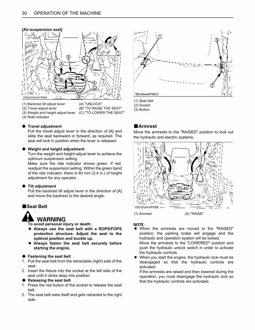
OPERATION OF THE MACHINE30
[Air-suspension seat]
C Travel adjustmentPull the travel adjust lever in the direction of [A] andslide the seat backward or forward, as required. Theseat will lock in position when the lever is released.
C Weight and height adjustmentTurn the weight and height adjust lever to achieve theoptimum suspension setting.Make sure the ride indicator shows green. If red,readjust the suspension setting. Within the green bandof the ride indicator, there is 60 mm (2.4 in.) of heightadjustment for any operator.
C Tilt adjustmentPull the backrest tilt adjust lever in the direction of [A]and move the backrest to the desired angle.
BSeat Belt
To avoid personal injury or death:A Always use the seat belt with a ROPS/FOPS
protection structure. Adjust the seat to theoptimal position and buckle up.
A Always fasten the seat belt securely beforestarting the engine.
C Fastening the seat belt1. Pull the seat belt from the retractable (right) side of the
seat.2. Insert the fixture into the socket at the left side of the
seat until it clicks deep into position.C Releasing the seat belt1. Press the red button of the socket to release the seat
belt.2. The seat belt reels itself and gets retracted to the right
side.
BArmrestMove the armrests to the "RAISED" position to lock outthe hydraulic and electric systems.
A When the armrests are moved to the "RAISED"position, the parking brake will engage and thehydraulic and operation system will be locked.Move the armrests to the "LOWERED" position andpush the hydraulic unlock switch in order to activatethe hydraulic controls.
A When you start the engine, the hydraulic lock must bedisengaged so that the hydraulic controls areactivated.If the armrests are raised and then lowered during theoperation, you must disengage the hydraulic lock sothat the hydraulic controls are activated.
(1) Backrest tilt adjust lever(2) Travel adjust lever(3) Weight and height adjust lever(4) Ride indicator
(A) "UNLOCK"(B) "TO RAISE THE SEAT"(C) "TO LOWER THE SEAT"
(1) Seat belt(2) Socket(3) Button
(1) Armrest (A) "RAISE"
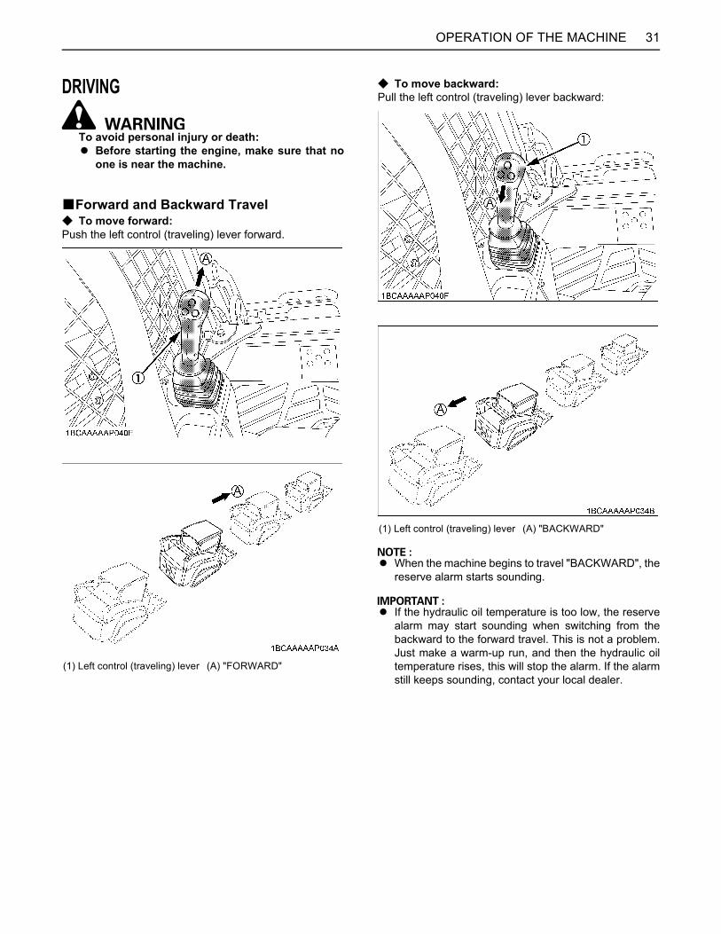
31OPERATION OF THE MACHINE
DRIVING
To avoid personal injury or death:A Before starting the engine, make sure that no
one is near the machine.
BForward and Backward TravelC To move forward:Push the left control (traveling) lever forward.
C To move backward:Pull the left control (traveling) lever backward:
A When the machine begins to travel "BACKWARD", thereserve alarm starts sounding.
A If the hydraulic oil temperature is too low, the reservealarm may start sounding when switching from thebackward to the forward travel. This is not a problem.Just make a warm-up run, and then the hydraulic oiltemperature rises, this will stop the alarm. If the alarmstill keeps sounding, contact your local dealer.
(1) Left control (traveling) lever (A) "FORWARD"
(1) Left control (traveling) lever (A) "BACKWARD"
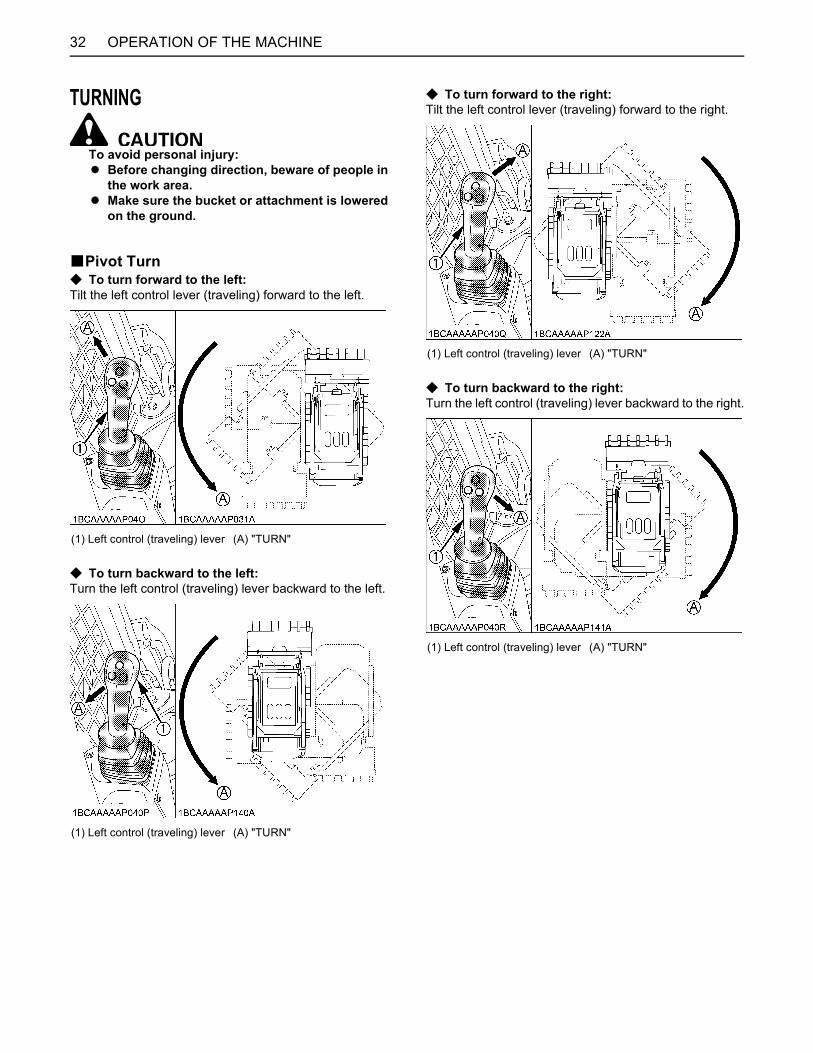
OPERATION OF THE MACHINE32
TURNING
To avoid personal injury: A Before changing direction, beware of people in
the work area.A Make sure the bucket or attachment is lowered
on the ground.
BPivot TurnC To turn forward to the left:Tilt the left control lever (traveling) forward to the left.
C To turn backward to the left:Turn the left control (traveling) lever backward to the left.
C To turn forward to the right:Tilt the left control lever (traveling) forward to the right.
C To turn backward to the right:Turn the left control (traveling) lever backward to the right.
(1) Left control (traveling) lever (A) "TURN"
(1) Left control (traveling) lever (A) "TURN"
(1) Left control (traveling) lever (A) "TURN"
(1) Left control (traveling) lever (A) "TURN"

33OPERATION OF THE MACHINE
BSpin TurnC To spin left:Tilt the left control (traveling) lever to the left.
C To spin right:Tilt the left control (traveling) lever to the right.
OPERATION OF THE LIFT ARMSC To lower the lift arms:Push the right control (front operating) lever forward:
(1) Left control (traveling) lever (A) "SPIN"
(1) Left control (traveling) lever (A) "SPIN"
(1) Right control (front operating) lever (A) "LOWER"
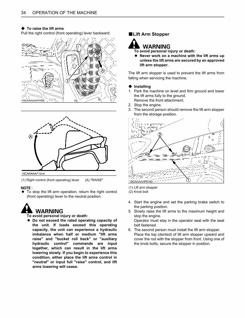
OPERATION OF THE MACHINE34
C To raise the lift armsPull the right control (front operating) lever backward.
A To stop the lift arm operation, return the right control(front operating) lever to the neutral position.
To avoid personal injury or death:A Do not exceed the rated operating capacity of
the unit. If loads exceed this operatingcapacity, the unit can experience a hydraulicimbalance when half or medium "lift armsraise" and "bucket roll back" or "auxiliaryhydraulic control" commands are inputtogether, which can result in the lift armslowering slowly. If you begin to experience thiscondition, either place the lift arms control in"neutral" or input full "raise" control, and liftarms lowering will cease.
BLift Arm Stopper
To avoid personal injury or death:A Never work on a machine with the lift arms up
unless the lift arms are secured by an approvedlift arm stopper.
The lift arm stopper is used to prevent the lift arms fromfalling when servicing the machine.
C Installing1. Park the machine on level and firm ground and lower
the lift arms fully to the ground.Remove the front attachment.
2. Stop the engine.3. The second person should remove the lift arm stopper
from the storage position.
4. Start the engine and set the parking brake switch tothe parking position.
5. Slowly raise the lift arms to the maximum height andstop the engine.Operator must stay in the operator seat with the seatbelt fastened.
6. The second person must install the lift arm stopper.Place the top (dented) of lift arm stopper upward andcover the rod with the stopper from front. Using one ofthe knob bolts, secure the stopper in position.
(1) Right control (front operating) lever (A) "RAISE"
(1) Lift arm stopper(2) Knob bolt
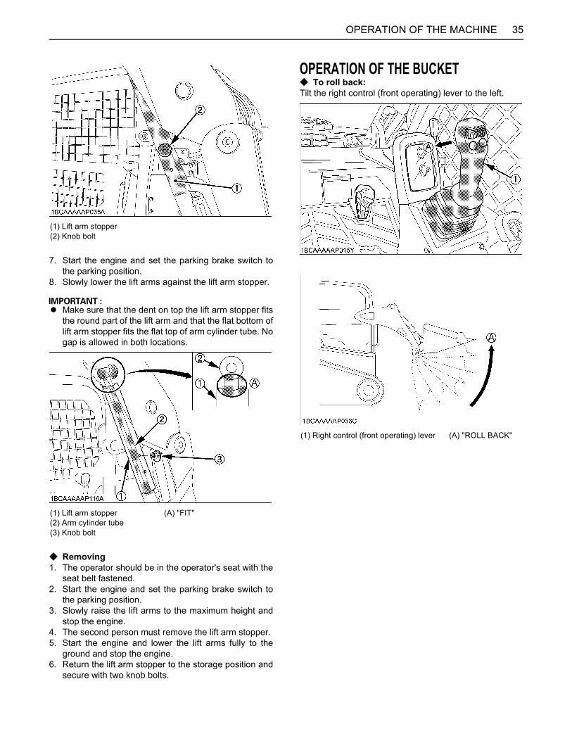
35OPERATION OF THE MACHINE
7. Start the engine and set the parking brake switch tothe parking position.
8. Slowly lower the lift arms against the lift arm stopper.
A Make sure that the dent on top the lift arm stopper fitsthe round part of the lift arm and that the flat bottom oflift arm stopper fits the flat top of arm cylinder tube. Nogap is allowed in both locations.
C Removing1. The operator should be in the operator's seat with the
seat belt fastened.2. Start the engine and set the parking brake switch to
the parking position.3. Slowly raise the lift arms to the maximum height and
stop the engine.4. The second person must remove the lift arm stopper.5. Start the engine and lower the lift arms fully to the
ground and stop the engine.6. Return the lift arm stopper to the storage position and
secure with two knob bolts.
OPERATION OF THE BUCKETC To roll back:Tilt the right control (front operating) lever to the left.
(1) Lift arm stopper(2) Knob bolt
(1) Lift arm stopper(2) Arm cylinder tube(3) Knob bolt
(A) "FIT"
(1) Right control (front operating) lever (A) "ROLL BACK"
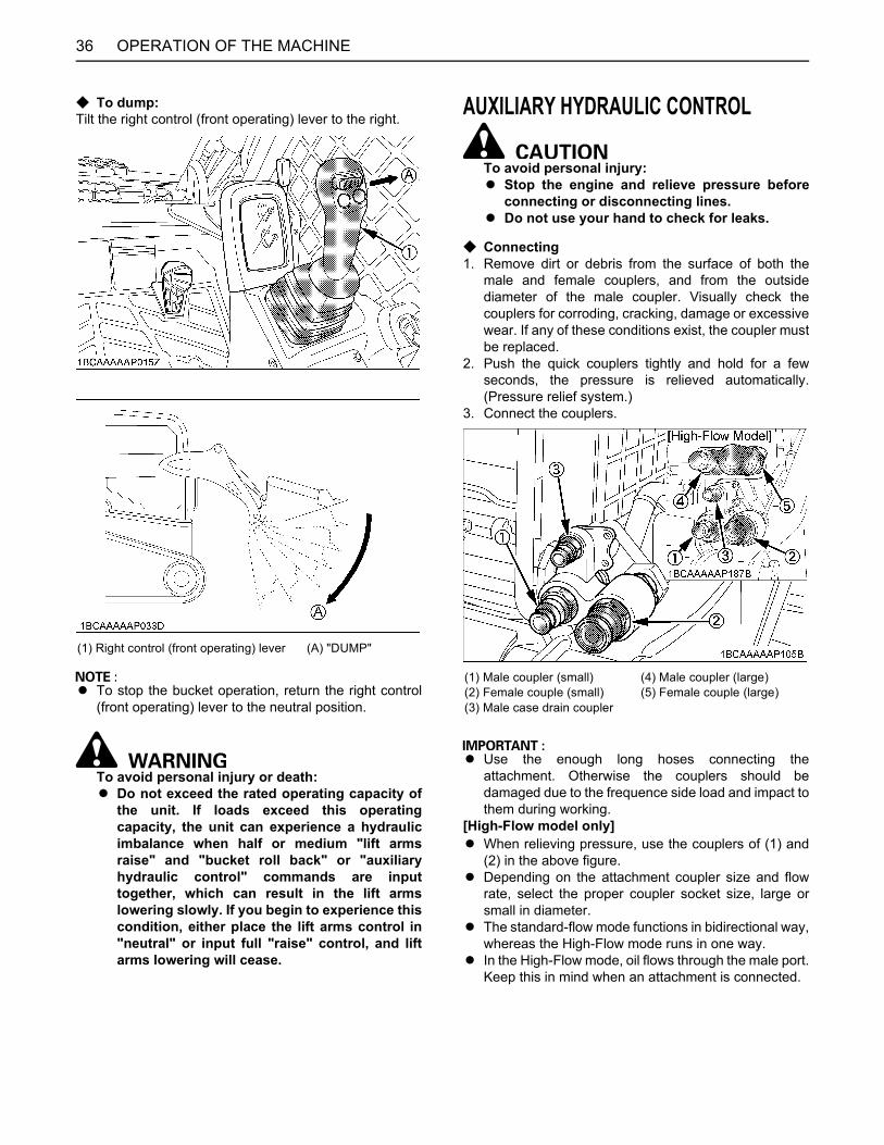
OPERATION OF THE MACHINE36
C To dump:Tilt the right control (front operating) lever to the right.
A To stop the bucket operation, return the right control(front operating) lever to the neutral position.
To avoid personal injury or death:A Do not exceed the rated operating capacity of
the unit. If loads exceed this operatingcapacity, the unit can experience a hydraulicimbalance when half or medium "lift armsraise" and "bucket roll back" or "auxiliaryhydraulic control" commands are inputtogether, which can result in the lift armslowering slowly. If you begin to experience thiscondition, either place the lift arms control in"neutral" or input full "raise" control, and liftarms lowering will cease.
AUXILIARY HYDRAULIC CONTROL
To avoid personal injury:A Stop the engine and relieve pressure before
connecting or disconnecting lines.A Do not use your hand to check for leaks.
C Connecting 1. Remove dirt or debris from the surface of both the
male and female couplers, and from the outsidediameter of the male coupler. Visually check thecouplers for corroding, cracking, damage or excessivewear. If any of these conditions exist, the coupler mustbe replaced.
2. Push the quick couplers tightly and hold for a fewseconds, the pressure is relieved automatically.(Pressure relief system.)
3. Connect the couplers.
A Use the enough long hoses connecting theattachment. Otherwise the couplers should bedamaged due to the frequence side load and impact tothem during working.
[High-Flow model only]A When relieving pressure, use the couplers of (1) and
(2) in the above figure.A Depending on the attachment coupler size and flow
rate, select the proper coupler socket size, large orsmall in diameter.
A The standard-flow mode functions in bidirectional way,whereas the High-Flow mode runs in one way.
A In the High-Flow mode, oil flows through the male port.Keep this in mind when an attachment is connected.
(1) Right control (front operating) lever (A) "DUMP"
(1) Male coupler (small)(2) Female couple (small)(3) Male case drain coupler
(4) Male coupler (large)(5) Female couple (large)
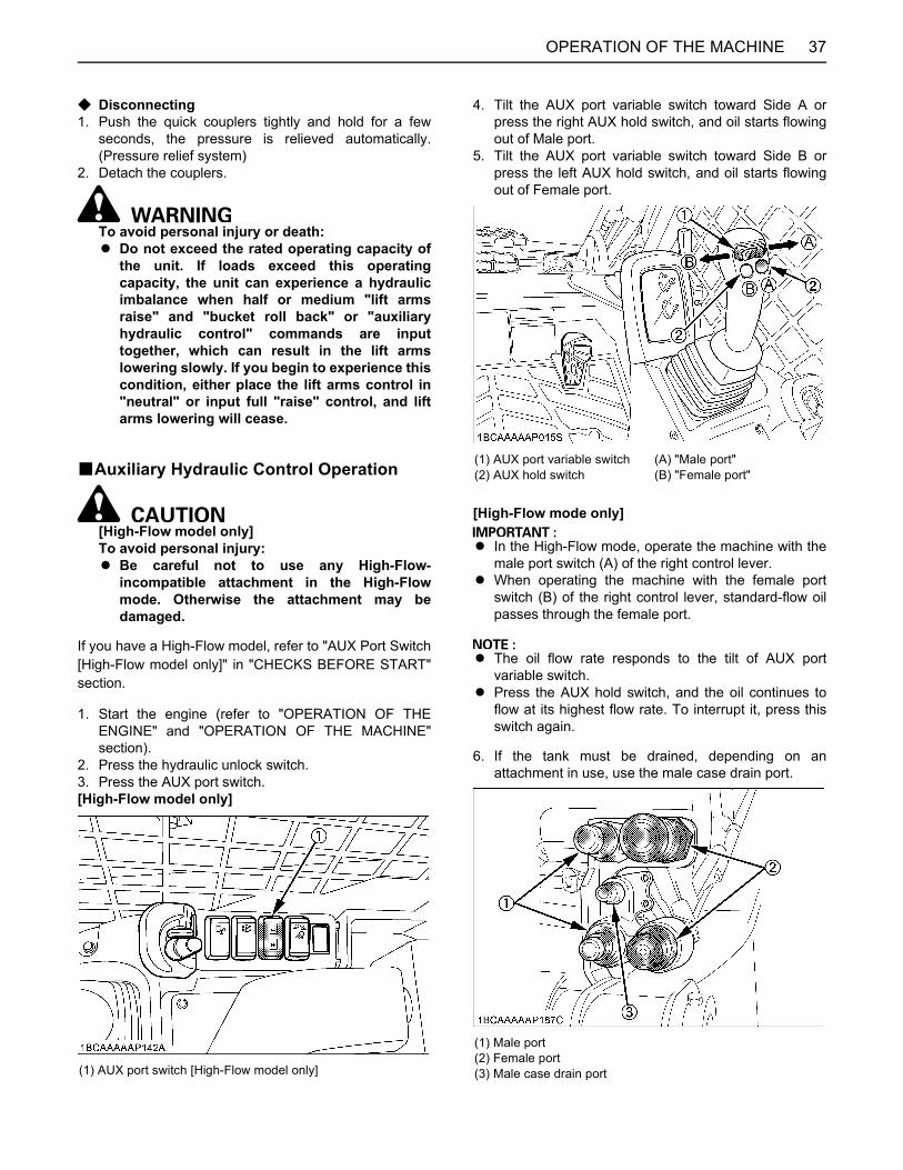
37OPERATION OF THE MACHINE
C Disconnecting1. Push the quick couplers tightly and hold for a few
seconds, the pressure is relieved automatically.(Pressure relief system)
2. Detach the couplers.
To avoid personal injury or death:A Do not exceed the rated operating capacity of
the unit. If loads exceed this operatingcapacity, the unit can experience a hydraulicimbalance when half or medium "lift armsraise" and "bucket roll back" or "auxiliaryhydraulic control" commands are inputtogether, which can result in the lift armslowering slowly. If you begin to experience thiscondition, either place the lift arms control in"neutral" or input full "raise" control, and liftarms lowering will cease.
BAuxiliary Hydraulic Control Operation
[High-Flow model only]To avoid personal injury:A Be careful not to use any High-Flow-
incompatible attachment in the High-Flowmode. Otherwise the attachment may bedamaged.
If you have a High-Flow model, refer to "AUX Port Switch[High-Flow model only]" in "CHECKS BEFORE START"section.
1. Start the engine (refer to "OPERATION OF THEENGINE" and "OPERATION OF THE MACHINE"section).
2. Press the hydraulic unlock switch.3. Press the AUX port switch.[High-Flow model only]
4. Tilt the AUX port variable switch toward Side A orpress the right AUX hold switch, and oil starts flowingout of Male port.
5. Tilt the AUX port variable switch toward Side B orpress the left AUX hold switch, and oil starts flowingout of Female port.
[High-Flow mode only]
A In the High-Flow mode, operate the machine with themale port switch (A) of the right control lever.
A When operating the machine with the female portswitch (B) of the right control lever, standard-flow oilpasses through the female port.
A The oil flow rate responds to the tilt of AUX portvariable switch.
A Press the AUX hold switch, and the oil continues toflow at its highest flow rate. To interrupt it, press thisswitch again.
6. If the tank must be drained, depending on anattachment in use, use the male case drain port.
(1) AUX port switch [High-Flow model only]
(1) AUX port variable switch(2) AUX hold switch
(A) "Male port"(B) "Female port"
(1) Male port(2) Female port(3) Male case drain port
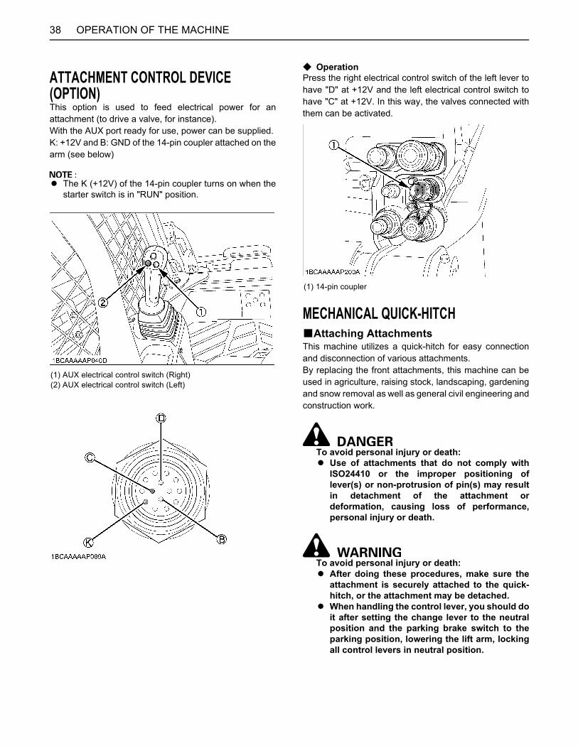
OPERATION OF THE MACHINE38
ATTACHMENT CONTROL DEVICE (OPTION)This option is used to feed electrical power for anattachment (to drive a valve, for instance).With the AUX port ready for use, power can be supplied.K: +12V and B: GND of the 14-pin coupler attached on thearm (see below)
A The K (+12V) of the 14-pin coupler turns on when thestarter switch is in "RUN" position.
C OperationPress the right electrical control switch of the left lever tohave "D" at +12V and the left electrical control switch tohave "C" at +12V. In this way, the valves connected withthem can be activated.
MECHANICAL QUICK-HITCHBAttaching AttachmentsThis machine utilizes a quick-hitch for easy connectionand disconnection of various attachments.By replacing the front attachments, this machine can beused in agriculture, raising stock, landscaping, gardeningand snow removal as well as general civil engineering andconstruction work.
To avoid personal injury or death:A Use of attachments that do not comply with
ISO24410 or the improper positioning oflever(s) or non-protrusion of pin(s) may resultin detachment of the attachment ordeformation, causing loss of performance,personal injury or death.
To avoid personal injury or death:A After doing these procedures, make sure the
attachment is securely attached to the quick-hitch, or the attachment may be detached.
A When handling the control lever, you should doit after setting the change lever to the neutralposition and the parking brake switch to theparking position, lowering the lift arm, lockingall control levers in neutral position.
(1) AUX electrical control switch (Right)(2) AUX electrical control switch (Left)
(1) 14-pin coupler
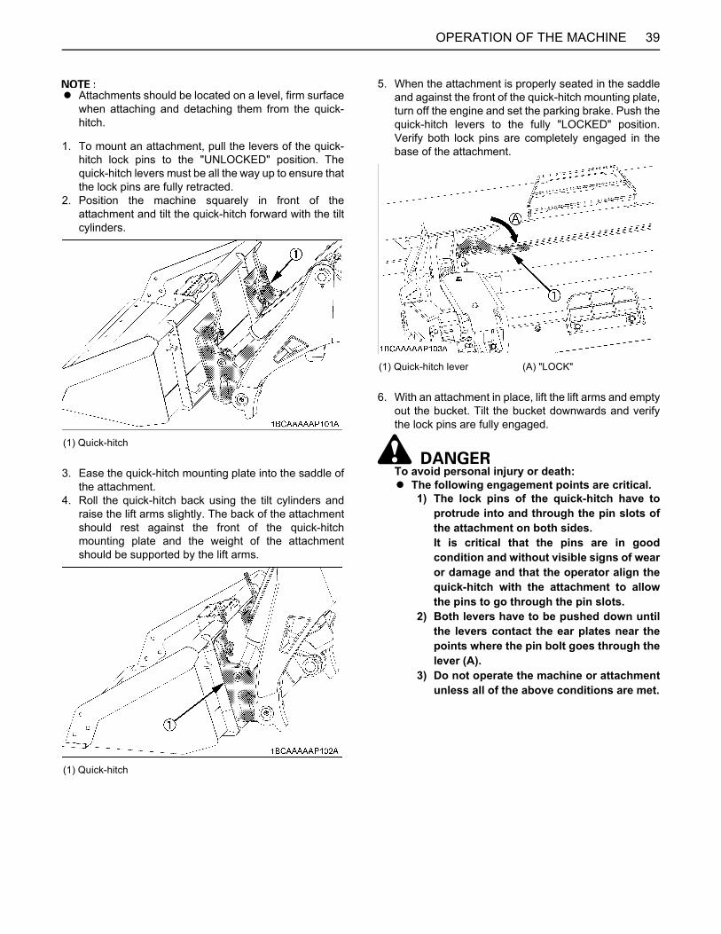
39OPERATION OF THE MACHINE
A Attachments should be located on a level, firm surfacewhen attaching and detaching them from the quick-hitch.
1. To mount an attachment, pull the levers of the quick-hitch lock pins to the "UNLOCKED" position. Thequick-hitch levers must be all the way up to ensure thatthe lock pins are fully retracted.
2. Position the machine squarely in front of theattachment and tilt the quick-hitch forward with the tiltcylinders.
3. Ease the quick-hitch mounting plate into the saddle ofthe attachment.
4. Roll the quick-hitch back using the tilt cylinders andraise the lift arms slightly. The back of the attachmentshould rest against the front of the quick-hitchmounting plate and the weight of the attachmentshould be supported by the lift arms.
5. When the attachment is properly seated in the saddleand against the front of the quick-hitch mounting plate,turn off the engine and set the parking brake. Push thequick-hitch levers to the fully "LOCKED" position.Verify both lock pins are completely engaged in thebase of the attachment.
6. With an attachment in place, lift the lift arms and emptyout the bucket. Tilt the bucket downwards and verifythe lock pins are fully engaged.
To avoid personal injury or death:A The following engagement points are critical.
1) The lock pins of the quick-hitch have toprotrude into and through the pin slots ofthe attachment on both sides.It is critical that the pins are in goodcondition and without visible signs of wearor damage and that the operator align thequick-hitch with the attachment to allowthe pins to go through the pin slots.
2) Both levers have to be pushed down untilthe levers contact the ear plates near thepoints where the pin bolt goes through thelever (A).
3) Do not operate the machine or attachmentunless all of the above conditions are met.
(1) Quick-hitch
(1) Quick-hitch
(1) Quick-hitch lever (A) "LOCK"

OPERATION OF THE MACHINE40
7. Visually verify when pushing the quick-hitch levers intolocked position that the lock pins protrude through theslot.
8. When attaching different attachments visually inspectfor broken or damaged pins. If broken or damagedpins are found, replace before using. Use of brokenpins may result in detachment or deformation, causingloss of performance, personal injury or death.
9. You are now ready to use the attachment.
To avoid personal injury or machine damage:A Never operate or transport attachments which
are not attached completely.A Always replace damaged hardware
immediately.
BDetaching Attachments1. Lower the attachment to ground level with the
attachment slightly in the rolled back position. Stop theengine (the parking brake automatically engages.).
2. Disconnect the attachment's electrical harness andhydraulic lines from the lift arms if equipped.
3. Pull the quick-hitch lever up to the unlocked position torelease the lock pins.
4. While sitting in the machine operator's seat, start theengine and slowly move the right control (frontoperating) lever to the "DUMP" position until theattachment is pushed away from the quick-hitch.
5. Lower the lift arms so that the quick-hitch mountingplate clears the attachment saddle.
6. Back away from the attachment slowly.7. If an attachment is not going to be attached to the
quick-hitch immediately, push the lever of the quick-hitch to the locked position to prevent damage to thelever assembly.
HYDRAULIC QUICK-HITCH (OPTION)BAttaching Attachments
A Attachments should be located on a level, firm surfacewhen attaching and detaching them from the quick-hitch.
1. Push the hydraulic quick-hitch switch in "UNLOCKED"position and hold it to make sure the levers are up("UNLOCKED" position).
(1) Lever(2) Ear plate(3) Lock pin(4) Pin slot
(A) "The lever contacts the ear plate at the points."(B) "The pin protrudes through the slot."
(1) Hydraulic quick-hitch switch (A) "UNLOCK" position(B) "LOCK" position
(1) Quick-hitch lever (A) "UNLOCK"
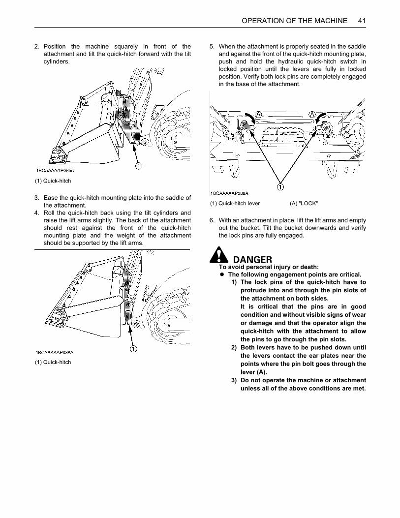
41OPERATION OF THE MACHINE
2. Position the machine squarely in front of theattachment and tilt the quick-hitch forward with the tiltcylinders.
3. Ease the quick-hitch mounting plate into the saddle ofthe attachment.
4. Roll the quick-hitch back using the tilt cylinders andraise the lift arms slightly. The back of the attachmentshould rest against the front of the quick-hitchmounting plate and the weight of the attachmentshould be supported by the lift arms.
5. When the attachment is properly seated in the saddleand against the front of the quick-hitch mounting plate,push and hold the hydraulic quick-hitch switch inlocked position until the levers are fully in lockedposition. Verify both lock pins are completely engagedin the base of the attachment.
6. With an attachment in place, lift the lift arms and emptyout the bucket. Tilt the bucket downwards and verifythe lock pins are fully engaged.
To avoid personal injury or death:A The following engagement points are critical.
1) The lock pins of the quick-hitch have toprotrude into and through the pin slots ofthe attachment on both sides.It is critical that the pins are in goodcondition and without visible signs of wearor damage and that the operator align thequick-hitch with the attachment to allowthe pins to go through the pin slots.
2) Both levers have to be pushed down untilthe levers contact the ear plates near thepoints where the pin bolt goes through thelever (A).
3) Do not operate the machine or attachmentunless all of the above conditions are met.
(1) Quick-hitch
(1) Quick-hitch
(1) Quick-hitch lever (A) "LOCK"
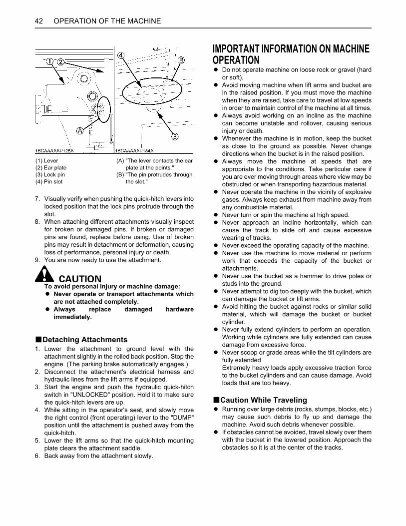
OPERATION OF THE MACHINE42
7. Visually verify when pushing the quick-hitch levers intolocked position that the lock pins protrude through theslot.
8. When attaching different attachments visually inspectfor broken or damaged pins. If broken or damagedpins are found, replace before using. Use of brokenpins may result in detachment or deformation, causingloss of performance, personal injury or death.
9. You are now ready to use the attachment.
To avoid personal injury or machine damage:A Never operate or transport attachments which
are not attached completely.A Always replace damaged hardware
immediately.
BDetaching Attachments1. Lower the attachment to ground level with the
attachment slightly in the rolled back position. Stop theengine. (The parking brake automatically engages.)
2. Disconnect the attachment's electrical harness andhydraulic lines from the lift arms if equipped.
3. Start the engine and push the hydraulic quick-hitchswitch in "UNLOCKED" position. Hold it to make surethe quick-hitch levers are up.
4. While sitting in the operator's seat, and slowly movethe right control (front operating) lever to the "DUMP"position until the attachment is pushed away from thequick-hitch.
5. Lower the lift arms so that the quick-hitch mountingplate clears the attachment saddle.
6. Back away from the attachment slowly.
IMPORTANT INFORMATION ON MACHINE OPERATIONA Do not operate machine on loose rock or gravel (hard
or soft).A Avoid moving machine when lift arms and bucket are
in the raised position. If you must move the machinewhen they are raised, take care to travel at low speedsin order to maintain control of the machine at all times.
A Always avoid working on an incline as the machinecan become unstable and rollover, causing seriousinjury or death.
A Whenever the machine is in motion, keep the bucketas close to the ground as possible. Never changedirections when the bucket is in the raised position.
A Always move the machine at speeds that areappropriate to the conditions. Take particular care ifyou are ever moving through areas where view may beobstructed or when transporting hazardous material.
A Never operate the machine in the vicinity of explosivegases. Always keep exhaust from machine away fromany combustible material.
A Never turn or spin the machine at high speed.A Never approach an incline horizontally, which can
cause the track to slide off and cause excessivewearing of tracks.
A Never exceed the operating capacity of the machine. A Never use the machine to move material or perform
work that exceeds the capacity of the bucket orattachments.
A Never use the bucket as a hammer to drive poles orstuds into the ground.
A Never attempt to dig too deeply with the bucket, whichcan damage the bucket or lift arms.
A Avoid hitting the bucket against rocks or similar solidmaterial, which will damage the bucket or bucketcylinder.
A Never fully extend cylinders to perform an operation.Working while cylinders are fully extended can causedamage from excessive force.
A Never scoop or grade areas while the tilt cylinders arefully extendedExtremely heavy loads apply excessive traction forceto the bucket cylinders and can cause damage. Avoidloads that are too heavy.
BCaution While TravelingA Running over large debris (rocks, stumps, blocks, etc.)
may cause such debris to fly up and damage themachine. Avoid such debris whenever possible.
A If obstacles cannot be avoided, travel slowly over themwith the bucket in the lowered position. Approach theobstacles so it is at the center of the tracks.
(1) Lever(2) Ear plate(3) Lock pin(4) Pin slot
(A) "The lever contacts the ear plate at the points."(B) "The pin protrudes through the slot."
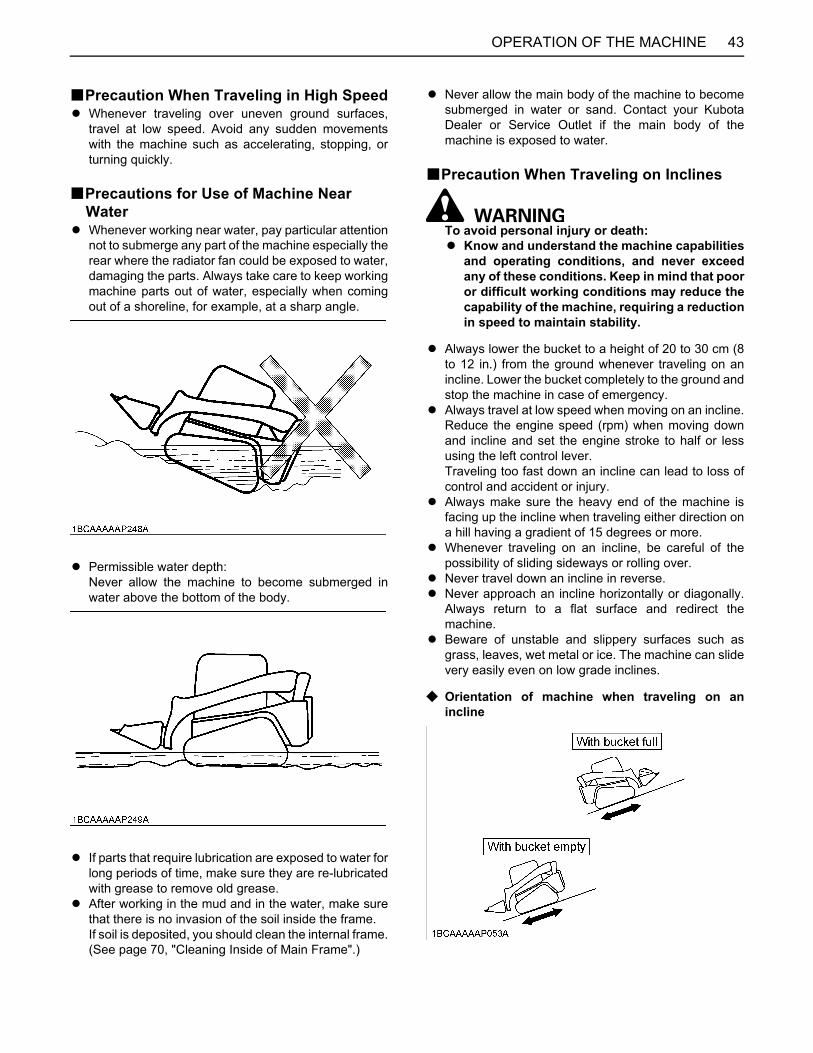
43OPERATION OF THE MACHINE
BPrecaution When Traveling in High SpeedA Whenever traveling over uneven ground surfaces,
travel at low speed. Avoid any sudden movementswith the machine such as accelerating, stopping, orturning quickly.
BPrecautions for Use of Machine Near Water
A Whenever working near water, pay particular attentionnot to submerge any part of the machine especially therear where the radiator fan could be exposed to water,damaging the parts. Always take care to keep workingmachine parts out of water, especially when comingout of a shoreline, for example, at a sharp angle.
A Permissible water depth:Never allow the machine to become submerged inwater above the bottom of the body.
A If parts that require lubrication are exposed to water forlong periods of time, make sure they are re-lubricatedwith grease to remove old grease.
A After working in the mud and in the water, make surethat there is no invasion of the soil inside the frame.If soil is deposited, you should clean the internal frame.(See page 70, "Cleaning Inside of Main Frame".)
A Never allow the main body of the machine to becomesubmerged in water or sand. Contact your KubotaDealer or Service Outlet if the main body of themachine is exposed to water.
BPrecaution When Traveling on Inclines
To avoid personal injury or death:A Know and understand the machine capabilities
and operating conditions, and never exceedany of these conditions. Keep in mind that pooror difficult working conditions may reduce thecapability of the machine, requiring a reductionin speed to maintain stability.
A Always lower the bucket to a height of 20 to 30 cm (8to 12 in.) from the ground whenever traveling on anincline. Lower the bucket completely to the ground andstop the machine in case of emergency.
A Always travel at low speed when moving on an incline.Reduce the engine speed (rpm) when moving downand incline and set the engine stroke to half or lessusing the left control lever. Traveling too fast down an incline can lead to loss ofcontrol and accident or injury.
A Always make sure the heavy end of the machine isfacing up the incline when traveling either direction ona hill having a gradient of 15 degrees or more.
A Whenever traveling on an incline, be careful of thepossibility of sliding sideways or rolling over.
A Never travel down an incline in reverse.A Never approach an incline horizontally or diagonally.
Always return to a flat surface and redirect themachine.
A Beware of unstable and slippery surfaces such asgrass, leaves, wet metal or ice. The machine can slidevery easily even on low grade inclines.
C Orientation of machine when traveling on anincline
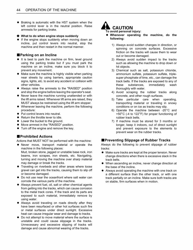
OPERATION OF THE MACHINE44
A Braking is automatic with the HST system when theleft control lever is in the neutral position. Raisearmrests for parking brake.
C What to do when engine stops suddenlyA If the engine stops suddenly when moving down an
incline, put control levers into neutral, stop themachine and then restart in the normal manner.
BParking on an InclineA It is best to park the machine on firm, level ground
using the parking brake but if you must park themachine on an incline, make sure you block it toprevent any movement.
A Make sure the machine is highly visible when parkingnear streets by using barriers, appropriate cautionsigns, lights, etc. to avoid any accident or collision withother vehicles.
A Always raise the armrests to the "RAISED" positionand stop the engine before leaving the operator's seat.
A Never leave the machine running unattended or withthe lift arms raised. Whenever lift arms are raised, theyMUST always be restrained using the lift arm stopper.
A Whenever leaving the machine, perform the followingprocedure:
A Put control levers into neutral.A Return the throttle lever to idle.A Lower the bucket to the ground.A Move armrest in the "RAISED" position.A Turn off the engine and remove the key.
BProhibited ActionsActions that MUST NOT be performed with the machine:A Never move, transport material or operate the
machine in the following places:Mud, broken stone, jagged or unstable base rock, ironbeams, iron scrapes, iron sheets, etc. Navigating,turning and moving the machine over sharp materialmay damage or break the tracks.
A Traveling on riverbeds and other areas where loosegravel can get into the tracks, causing them to slip offor become damaged.
A Do not use near the oceanfront where salt water cancorrode the various parts of the machine.
A Always prevent fuel, oil, salt or other chemical agentsfrom getting into the tracks, which can cause corrosionto the metal track cores. If the track and its parts areexposed to such material, immediately remove byusing water.
A Always avoid traveling on roads directly after theyhave been resurfaced or other hot surfaces such fireor metal surfaces under direct sunlight. Excessiveheat can cause irregular wear and damage to tracks.
A Do not attempt to move material where the surface isunstable and could cause slippage in the tracks.Unnecessary and excessive slipping of tracks willdamage and cause abnormal wearing of the tracks.
To avoid personal injury:A Whenever operating the machine, do the
following:
1) Always avoid sudden changes in direction, orspinning on concrete surfaces. Excessivefriction on the tracks will cause them to wearout or become damaged.
2) Always avoid sudden impact to the trackssuch as allowing the machine to drop down orhit objects.
3) Chemical such as salt, potassium chloride,ammonium sulfate, potassium sulfate, triple-super phosphate of lime, etc., can damage thetrack belts. If the tracks are exposed to any ofthese substances, immediately washthoroughly with water.
4) Avoid scraping the rubber tracks alongconcrete, and other rough surfaces.
5) Take particular care when operating,transporting material or traveling in snowyconditions or on ice as tracks may slip.
6) Operate the machine between -20 C and+50 C (-4 to 122 F) for proper functioning ofrubber track belts.
7) If machine must be stored for 3 months orlonger, keep it indoors, out of direct sunlightand prevent exposure to the elements toprevent wear on the rubber tracks.
BPreventing Slippage of Rubber TracksAlways do the following to prevent slippage of rubbertracks:A Make sure tracks are kept at the proper tension. Never
change directions when there is excessive slack in thetrack belts.
A When ascending an incline, never change direction atthe base of the incline.
A Always avoid operating the machine with one track ona different surface than the other track, or with onetrack partially on an incline. Make sure both tracks areon stable, firm surfaces when in motion.

45LIFTING THE MACHINE
LIFTING THE MACHINE
To avoid serious injury or death:A The instructions for safe lifting are described
here. Read these instructions carefully beforelifting the machine. Make sure that theoperating personnel read the operator'smanual carefully before lifting.
A Select a firm level surface, lower the workingequipment to the ground, stop the engine, set arm restto locked position and apply parking brake switch sothe unit cannot roll.
A Do not lift loads that exceed the maximum ratedcapacity of the hoist and attaching hardware.
A See specifications for attaching hardware and choosehardware suitable for the weight, size andconfiguration of the load.
A Assess the center of gravity of the load, position thehook directly over the load and lift the load so that itremains horizontal.
A Do not enter and do not allow others to enter theworking area under the suspended load and do notmove the load over people. The load must only bemoved in an area where the equilibrium can bemaintained.
A Always inspect the attaching hardware, includingchains, hooks and master links before each use. Donot use any worn or damaged attaching hardware or ifthe safety latch is missing.
A Do not use attaching hardware, including chains,hooks and master links, in extreme temperature orother environmental conditions that exceed themanufacturer's specifications.
A Load disengagement can cause severe injury ordeath. The use of a hook with a safety latch or othermaster link device does not preclude inadvertentdetachment of a slack sling load from the hook ormaster link. Visual verification of proper hook orshackle engagement is required in all instances.
A Comply with all Federal, State and Local regulationsand safety standards before lifting the machine.
A Do not use the holes on the roof structure to lift themachine.
A Make sure the lifting chains, hooks and master linksare strong enough to withstand the load being lifted.
A Be sure that the hooks used have safely latch.A Before lifting, be sure attachments are properly
attached.
PreparationsA Lifting chains (with hook at each end)
Approximate overall length: 3.43 m (135 in.), 2 pc.Approximate overall length: 8.84 m (348 in.), 1 pc.
A Pads (to protect the machine and lifting chain)A Master links, 2pc.
* SVL weight with standard (non-hydraulic) bucket** Recommended chain, master link and attachment hardware shall meet OSHA regulations and applicable ANSI (American National Standards Institute), NACM (National Association of Chain Manufacturers), and Federal standards
Model name SVL 90-2
Model Type Open Cab Closed Cab
CTL weight * kg (lbs.) 5015 (11056) 5140 (11332)
Recommended Chain Working Load Limit > 2565 kg (5655 lbs) **
3/8” Lifting Grade 80 Alloy
Recommended Master Link Working Load Limit > 5125 kg (11300 lbs) **
Size not specified
Recommended Attachment Hardware Working Load Limit > 2565 kg (5655 lbs) **
Size not specified
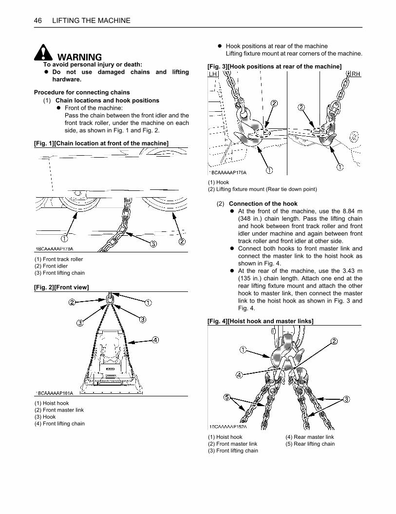
LIFTING THE MACHINE46
To avoid personal injury or death:A Do not use damaged chains and lifting
hardware.
Procedure for connecting chains(1) Chain locations and hook positions
A Front of the machine: Pass the chain between the front idler and thefront track roller, under the machine on eachside, as shown in Fig. 1 and Fig. 2.
[Fig. 1][Chain location at front of the machine]
[Fig. 2][Front view]
A Hook positions at rear of the machineLifting fixture mount at rear corners of the machine.
[Fig. 3][Hook positions at rear of the machine]
(2) Connection of the hookA At the front of the machine, use the 8.84 m
(348 in.) chain length. Pass the lifting chainand hook between front track roller and frontidler under machine and again between fronttrack roller and front idler at other side.
A Connect both hooks to front master link andconnect the master link to the hoist hook asshown in Fig. 4.
A At the rear of the machine, use the 3.43 m(135 in.) chain length. Attach one end at therear lifting fixture mount and attach the otherhook to master link, then connect the masterlink to the hoist hook as shown in Fig. 3 andFig. 4.
[Fig. 4][Hoist hook and master links]
(1) Front track roller(2) Front idler(3) Front lifting chain
(1) Hoist hook(2) Front master link(3) Hook(4) Front lifting chain
(1) Hook(2) Lifting fixture mount (Rear tie down point)
(1) Hoist hook(2) Front master link(3) Front lifting chain
(4) Rear master link(5) Rear lifting chain
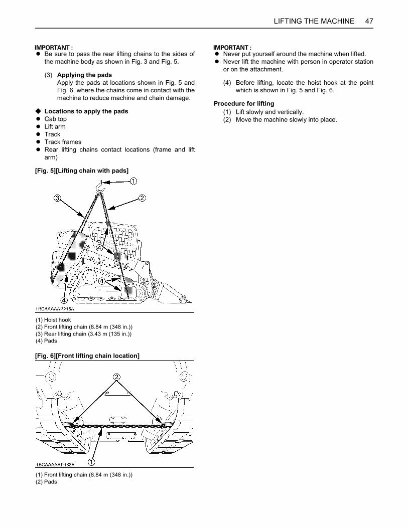
47LIFTING THE MACHINE
A Be sure to pass the rear lifting chains to the sides ofthe machine body as shown in Fig. 3 and Fig. 5.
(3) Applying the padsApply the pads at locations shown in Fig. 5 andFig. 6, where the chains come in contact with themachine to reduce machine and chain damage.
C Locations to apply the padsA Cab topA Lift armA TrackA Track framesA Rear lifting chains contact locations (frame and lift
arm)
[Fig. 5][Lifting chain with pads]
[Fig. 6][Front lifting chain location]
A Never put yourself around the machine when lifted.A Never lift the machine with person in operator station
or on the attachment.
(4) Before lifting, locate the hoist hook at the pointwhich is shown in Fig. 5 and Fig. 6.
Procedure for lifting(1) Lift slowly and vertically.(2) Move the machine slowly into place.
(1) Hoist hook(2) Front lifting chain (8.84 m (348 in.))(3) Rear lifting chain (3.43 m (135 in.))(4) Pads
(1) Front lifting chain (8.84 m (348 in.))(2) Pads
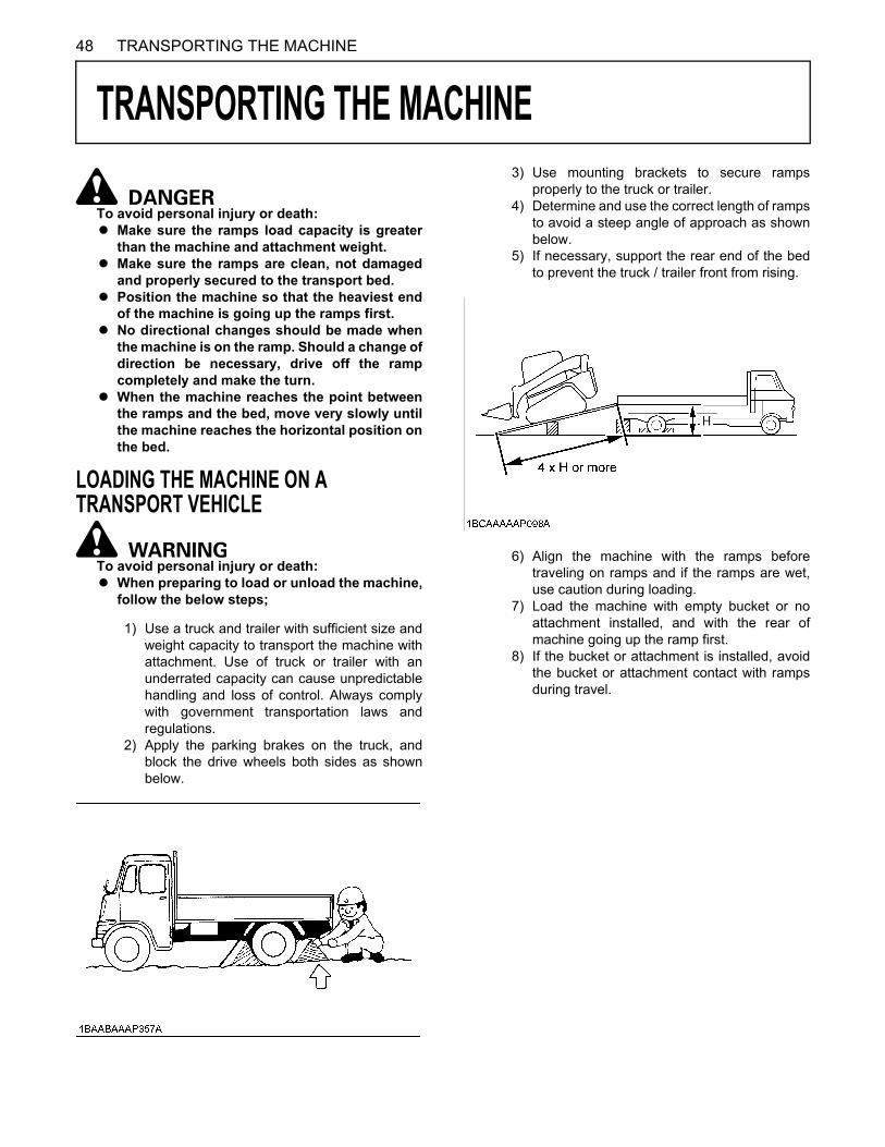
48 TRANSPORTING THE MACHINE
TRANSPORTING THE MACHINE
To avoid personal injury or death: A Make sure the ramps load capacity is greater
than the machine and attachment weight.A Make sure the ramps are clean, not damaged
and properly secured to the transport bed. A Position the machine so that the heaviest end
of the machine is going up the ramps first.A No directional changes should be made when
the machine is on the ramp. Should a change ofdirection be necessary, drive off the rampcompletely and make the turn.
A When the machine reaches the point betweenthe ramps and the bed, move very slowly untilthe machine reaches the horizontal position onthe bed.
LOADING THE MACHINE ON A TRANSPORT VEHICLE
To avoid personal injury or death:A When preparing to load or unload the machine,
follow the below steps;
1) Use a truck and trailer with sufficient size andweight capacity to transport the machine withattachment. Use of truck or trailer with anunderrated capacity can cause unpredictablehandling and loss of control. Always complywith government transportation laws andregulations.
2) Apply the parking brakes on the truck, andblock the drive wheels both sides as shownbelow.
3) Use mounting brackets to secure rampsproperly to the truck or trailer.
4) Determine and use the correct length of rampsto avoid a steep angle of approach as shownbelow.
5) If necessary, support the rear end of the bedto prevent the truck / trailer front from rising.
6) Align the machine with the ramps beforetraveling on ramps and if the ramps are wet,use caution during loading.
7) Load the machine with empty bucket or noattachment installed, and with the rear ofmachine going up the ramp first.
8) If the bucket or attachment is installed, avoidthe bucket or attachment contact with rampsduring travel.
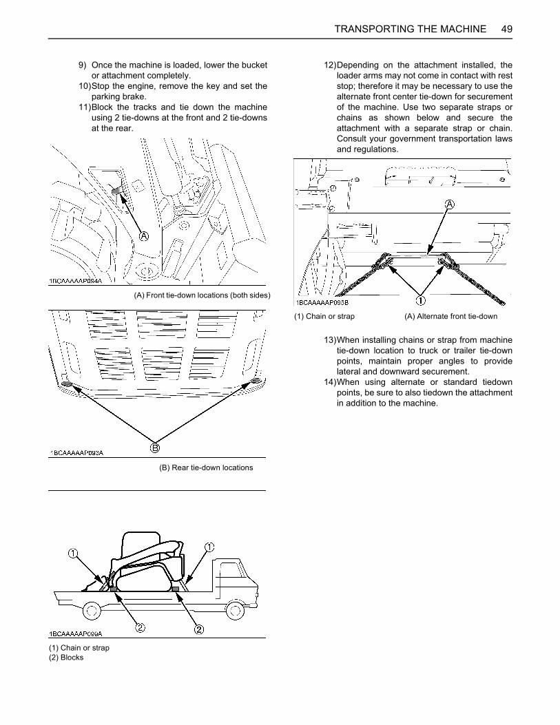
49TRANSPORTING THE MACHINE
9) Once the machine is loaded, lower the bucketor attachment completely.
10)Stop the engine, remove the key and set theparking brake.
11)Block the tracks and tie down the machineusing 2 tie-downs at the front and 2 tie-downsat the rear.
12)Depending on the attachment installed, theloader arms may not come in contact with reststop; therefore it may be necessary to use thealternate front center tie-down for securementof the machine. Use two separate straps orchains as shown below and secure theattachment with a separate strap or chain.Consult your government transportation lawsand regulations.
13)When installing chains or strap from machinetie-down location to truck or trailer tie-downpoints, maintain proper angles to providelateral and downward securement.
14)When using alternate or standard tiedownpoints, be sure to also tiedown the attachmentin addition to the machine.
(A) Front tie-down locations (both sides)
(B) Rear tie-down locations
(1) Chain or strap(2) Blocks
(1) Chain or strap (A) Alternate front tie-down
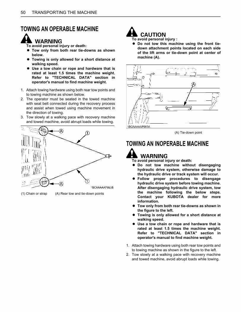
TRANSPORTING THE MACHINE50
TOWING AN OPERABLE MACHINE
To avoid personal injury or death: A Tow only from both rear tie-downs as shown
below.A Towing is only allowed for a short distance at
walking speed.A Use a tow chain or rope and hardware that is
rated at least 1.5 times the machine weight.Refer to "TECHNICAL DATA" section inoperator's manual to find machine weight.
1. Attach towing hardware using both rear tow points andto towing machine as shown below.
2. The operator must be seated in the towed machinewith seat belt connected during the recovery processand assist when towed using machine movement inthe direction of towing.
3. Tow slowly at a walking pace with recovery machineand towed machine, avoid abrupt loads while towing.
To avoid personal injury :A Do not tow this machine using the front tie-
down attachment points located on each sideof the lift arms or tie-down point at center ofmachine (A).
TOWING AN INOPERABLE MACHINE
To avoid personal injury or death:A Do not tow machine without disengaging
hydraulic drive system, otherwise damage tothe hydraulic drive or track system will occur.
A Follow proper procedures to disengagehydraulic drive system before towing machine.After disengaging hydraulic drive system, towthe machine following the below steps.Contact your KUBOTA dealer for moreinformation.
A Tow only from both rear tie-downs as shown inthe figure to the left.
A Towing is only allowed for a short distance atwalking speed.
A Use a tow chain or rope and hardware that israted at least 1.5 times the machine weight.Refer to "TECHNICAL DATA" section inoperator's manual to find machine weight.
1. Attach towing hardware using both rear tow points andto towing machine as shown in the figure to the left.
2. Tow slowly at a walking pace with recovery machineand towed machine, avoid abrupt loads while towing.
(1) Chain or strap (A) Rear tow and tie-down points
(A) Tie-down point
51MAINTENANCE
MAINTENANCE
To avoid personal injury:A Before doing maintenance work on the machine, place the machine on a firm, flat and level surface, lower
the lift arms slowly to the ground, stop the engine.
Whether the machine is properly lubricated and maintained directly determines the trouble frequency and service life of themachine. Periodically check and maintain your machine, and you will find in the long run that the jobs can be finished earlierand more economically.Shown in the Service Interval Chart below are the hours indicated on the hourmeter, practically, it will be convenient toschedule the time of inspection and maintenance according to the calendar (day, week, month) on the basis of the chart.If the machine is used in harder-than-usual working conditions, it must be checked and maintained at shorter intervals.
MAINTENANCE INTERVALSNo. Check points Measures
Hour meter indicatorInterval Ref.
page50 250 500 1000 1500 2000 3000
1 Coolantcheck Daily check (every 10 hrs) 59
change every 2 years 77
2 Fuel check Daily check (every 10 hrs) 60
3 Engine oilcheck Daily check (every 10 hrs) 60
change every 500 hrs 72
4 Hydraulic oilcheck Daily check (every 10 hrs) 61
change every 1000 hrs 74 *1
5 Greasing grease Daily check (every 10 hrs) 61
6 Radiator and oil cooler check Daily check (every 10 hrs) 62
7 Engine and electrical wiring check Daily check (every 10 hrs) 62
8 Water separator drain Daily check (every 10 hrs) 62
9 Washer liquid check Daily check (every 10 hrs) 63
10 Fuel tank drain every 50 hrs 66
11 Track tension check every 50 hrs 66
12 Battery condition check Daily check (every 10 hrs) 64
13 V-belt tensioncheck Daily check (every 10 hrs) 62
adjust every 250 hrs 69
14 Dust indicator Check Daily check (every 10 hrs) 63
15 Radiator hoses and clampscheck every 250 hrs 68
replace every 2 years 78
16 Inside of main frame clean every 250 hrs 70
17 Air cleaner element
Outer element
clean every 50 hrs 67 *2
@replace every 250 hrs 70 *2
Inner element replace every 250 hrs 70 *2
18 Fuel filter cartridge replace every 500 hrs 73 @
19 Engine oil filter cartridge replace every 500 hrs 72

52 MAINTENANCE
20 Drive unit oil change every 500 hrs 73
21 Breather filter replace every 500 hrs 73
22 Hydraulic return filter replace every 500 hrs 74
23 Hydraulic suction filter replace every 1000 hrs 74
24 Hydraulic oil filter replace every 500 hrs 74
25 Injector tip check every 1500 hrs 75 *3 @
26 Alternator and starter motor check every 2000 hrs 76
27 Oil separator element replace every 1500 hrs 75 @
28 PCV valve check every 1500 hrs 76 *3
29 EGR cooler check every 1500 hrs 76 *3 @
30 EGR system check every 3000 hrs 76 *3 @
31 Turbo charger check every 3000 hrs 76 *3 @
32 DPF clean every 3000 hrs 76 *3 @
33 Radiator system rinse every 2 years 77
34 Fuel line and intake air linecheck every 250 hrs 69
@replace every 2 years 78
35 Exhaust manifold (crack, gas, leakage and mounting screw) check every 1 year 76 *3
36 Intake air line for air leaks check every 1 year 76 *3
37 Boost sensor and AFS (Air flow sensor) check every 1 year 76 *3
38 Condition of DPF muffler check every 1 year 76 *3
39 DPF differential pressure sensor and piping for gas leak check every 1 year 76 *3
40 DPF exhaust gas temperature sensor check every 1 year 76 *3
41 EGR and piping for gas leak check every 1 year 76 *3
42 Closed breather related rubber piping replace every 2 years 79 *3
43DPF differential pressure sensor rubber piping (Front and back)
replace every 2 years 79 *3
44 Suction pipe downstream the AFS (Air flow sensor) replace every 2 years 79 *3
45 Boost sensor pressure rubber piping replace every 2 years 79 *3
46 EGR cooler hose replace every 2 years 79 *3
No. Check points MeasuresHour meter indicator
Interval Ref.page50 250 500 1000 1500 2000 3000

53MAINTENANCE
C Air-conditioner
First operation*1 When using a hydraulic hammer, change hydraulic oil and return filter according to the table on "Hydraulic OilChange (Including Replacing of the Suction Filter and Return Filter in the Hydraulic Tank) "EVERY 1000 SERVICEHOURS" in "REGULAR CHECKS AND MAINTENANCE WORK" section.*2 Clean and replace the air cleaner element more frequently if used under dusty conditions. When the filter is verydirty from dusty conditions, replace the filter. *3 Consult your local KUBOTA dealer for this service.A The items listed above (@ marked) are registered as emission related critical parts by KUBOTA in the U.S.EPA non-
road emission regulation. As the engine owner, you are responsible for the performance of the requiredmaintenance on the engine according to the above instruction. Please see the warranty Statement in detail.
No. Check points MeasuresHour meter indicator
Interval Ref.page50 250 500 1000 1500 2000 3000
1 Air filterclean every 250 hrs 70 *2
replace every 1000 hrs - *2
2 Air-conditioner condenser check every 250 hrs 71
3 Air-conditioner pipes and hosecheck every 1 year 76
replace every 2 years 79
4 Refrigerant (gas) check service as required 79
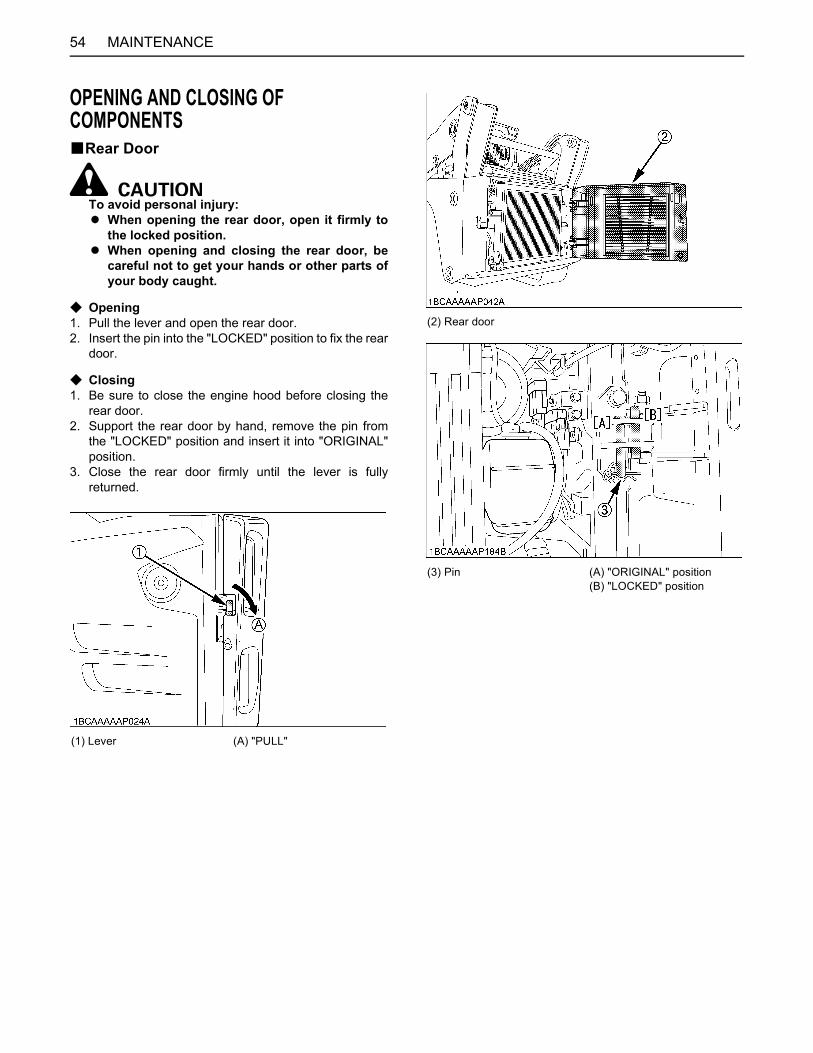
MAINTENANCE54
OPENING AND CLOSING OF COMPONENTSBRear Door
To avoid personal injury:A When opening the rear door, open it firmly to
the locked position.A When opening and closing the rear door, be
careful not to get your hands or other parts ofyour body caught.
C Opening1. Pull the lever and open the rear door.2. Insert the pin into the "LOCKED" position to fix the rear
door.
C Closing1. Be sure to close the engine hood before closing the
rear door.2. Support the rear door by hand, remove the pin from
the "LOCKED" position and insert it into "ORIGINAL"position.
3. Close the rear door firmly until the lever is fullyreturned.
(1) Lever (A) "PULL"
(2) Rear door
(3) Pin (A) "ORIGINAL" position(B) "LOCKED" position
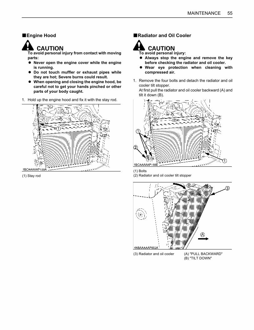
55MAINTENANCE
BEngine Hood
To avoid personal injury from contact with movingparts:A Never open the engine cover while the engine
is running.A Do not touch muffler or exhaust pipes while
they are hot; Severe burns could result.A When opening and closing the engine hood, be
careful not to get your hands pinched or otherparts of your body caught.
1. Hold up the engine hood and fix it with the stay rod.
BRadiator and Oil Cooler
To avoid personal injury:A Always stop the engine and remove the key
before checking the radiator and oil cooler.A Wear eye protection when cleaning with
compressed air.
1. Remove the four bolts and detach the radiator and oilcooler tilt stopper.At first pull the radiator and oil cooler backward (A) andtilt it down (B).
(1) Stay rod(1) Bolts(2) Radiator and oil cooler tilt stopper
(3) Radiator and oil cooler (A) "PULL BACKWARD"(B) "TILT DOWN"

MAINTENANCE56
A Before tilting the radiator and oil cooler, undo theradiator hose from the stay. Before positioning themback in place, secure the radiator hose to the stay sothat the hose does not get caught between the shroudand engine.
2. Place the radiator and oil cooler tilt stopper to preventthe tilted radiator and oil cooler from falling forward.
BWhere to Keep Operator's Manual
BTool Box1. Detach the floor mat.2. Remove the nuts and detach the cover.
(1) Radiator hose(2) Stay
(1) Radiator and oil cooler tilt stopper
(1) Operator's manual storage box(2) Storage space
(1) Floor mat
(2) Cover (3) Tool storage space
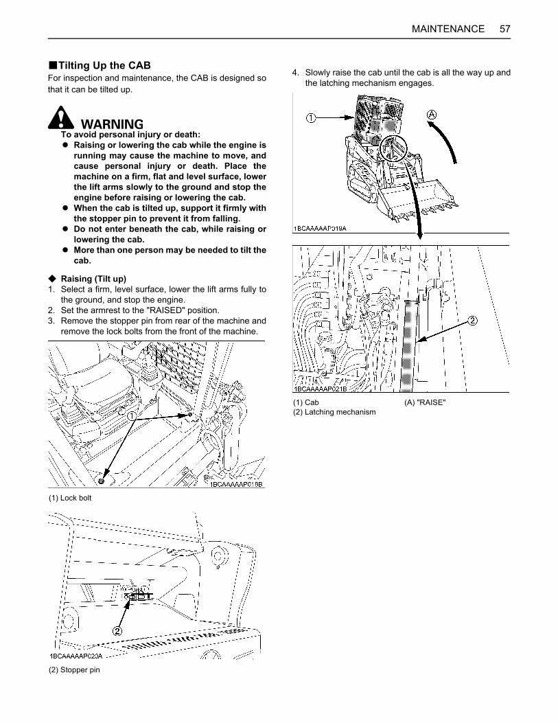
57MAINTENANCE
BTilting Up the CABFor inspection and maintenance, the CAB is designed sothat it can be tilted up.
To avoid personal injury or death:A Raising or lowering the cab while the engine is
running may cause the machine to move, andcause personal injury or death. Place themachine on a firm, flat and level surface, lowerthe lift arms slowly to the ground and stop theengine before raising or lowering the cab.
A When the cab is tilted up, support it firmly withthe stopper pin to prevent it from falling.
A Do not enter beneath the cab, while raising orlowering the cab.
A More than one person may be needed to tilt thecab.
C Raising (Tilt up)1. Select a firm, level surface, lower the lift arms fully to
the ground, and stop the engine.2. Set the armrest to the "RAISED" position.3. Remove the stopper pin from rear of the machine and
remove the lock bolts from the front of the machine.
4. Slowly raise the cab until the cab is all the way up andthe latching mechanism engages.
(1) Lock bolt
(2) Stopper pin
(1) Cab(2) Latching mechanism
(A) "RAISE"
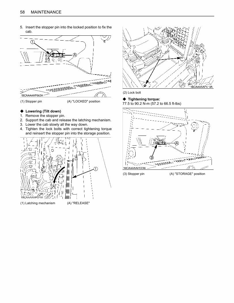
MAINTENANCE58
5. Insert the stopper pin into the locked position to fix thecab.
C Lowering (Tilt down)1. Remove the stopper pin.2. Support the cab and release the latching mechanism.3. Lower the cab slowly all the way down.4. Tighten the lock bolts with correct tightening torque
and reinsert the stopper pin into the storage position.
C Tightening torque:77.5 to 90.2 N-m (57.2 to 66.5 ft-lbs)(1) Stopper pin (A) "LOCKED" position
(1) Latching mechanism (A) "RELEASE"
(2) Lock bolt
(3) Stopper pin (A) "STORAGE" position
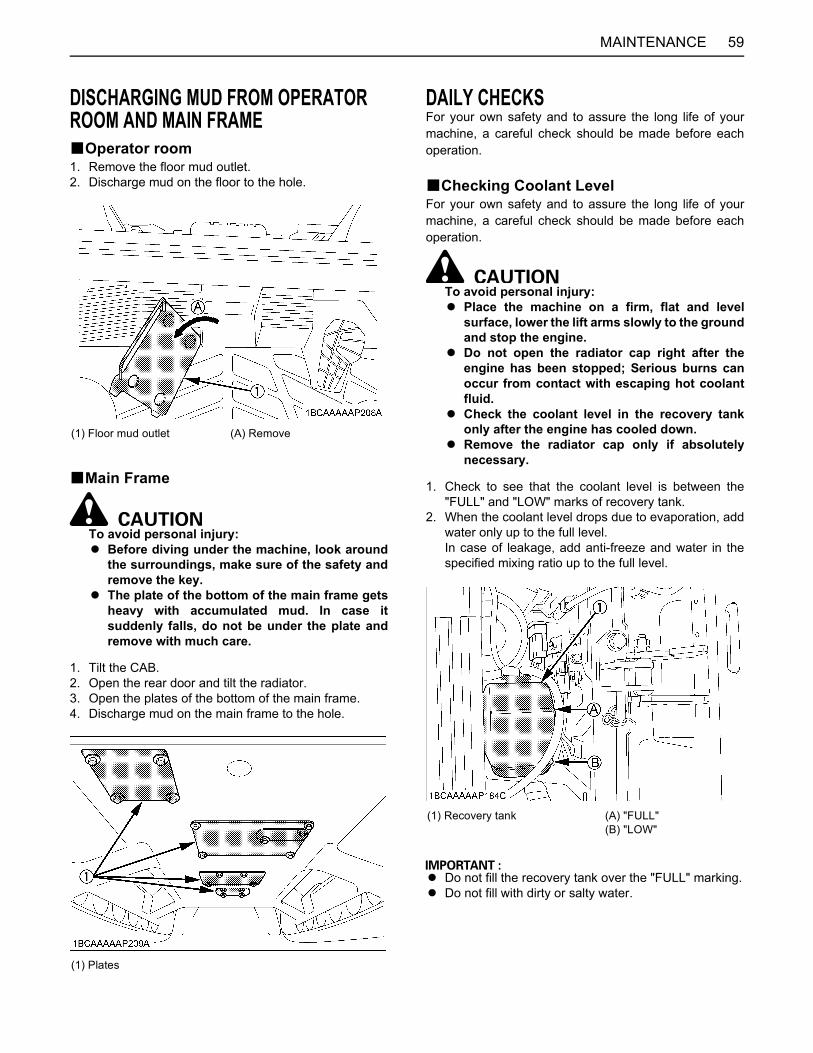
59MAINTENANCE
DISCHARGING MUD FROM OPERATOR ROOM AND MAIN FRAMEBOperator room1. Remove the floor mud outlet.2. Discharge mud on the floor to the hole.
BMain Frame
To avoid personal injury:A Before diving under the machine, look around
the surroundings, make sure of the safety andremove the key.
A The plate of the bottom of the main frame getsheavy with accumulated mud. In case itsuddenly falls, do not be under the plate andremove with much care.
1. Tilt the CAB.2. Open the rear door and tilt the radiator.3. Open the plates of the bottom of the main frame.4. Discharge mud on the main frame to the hole.
DAILY CHECKSFor your own safety and to assure the long life of yourmachine, a careful check should be made before eachoperation.
BChecking Coolant LevelFor your own safety and to assure the long life of yourmachine, a careful check should be made before eachoperation.
To avoid personal injury:A Place the machine on a firm, flat and level
surface, lower the lift arms slowly to the groundand stop the engine.
A Do not open the radiator cap right after theengine has been stopped; Serious burns canoccur from contact with escaping hot coolantfluid.
A Check the coolant level in the recovery tankonly after the engine has cooled down.
A Remove the radiator cap only if absolutelynecessary.
1. Check to see that the coolant level is between the"FULL" and "LOW" marks of recovery tank.
2. When the coolant level drops due to evaporation, addwater only up to the full level.In case of leakage, add anti-freeze and water in thespecified mixing ratio up to the full level.
A Do not fill the recovery tank over the "FULL" marking.A Do not fill with dirty or salty water.
(1) Floor mud outlet (A) Remove
(1) Plates
(1) Recovery tank (A) "FULL"(B) "LOW"
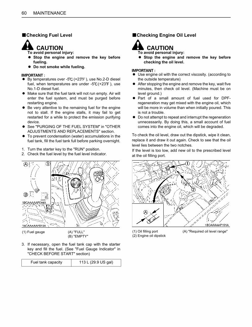
MAINTENANCE60
BChecking Fuel Level
To avoid personal injury:A Stop the engine and remove the key before
fueling.A Do not smoke while fueling.
A By temperatures over -5 (+23 ), use No.2-D dieselfuel, when temperatures are under -5 (+23 ), useNo.1-D diesel fuel.
A Make sure that the fuel tank will not run empty. Air willenter the fuel system, and must be purged beforerestarting engine.
A Be very attentive to the remaining fuel for the enginenot to stall. If the engine stalls, it may fail to getrestarted for a while to protect the emission purifyingdevice.
A See "PURGING OF THE FUEL SYSTEM" in "OTHERADJUSTMENTS AND REPLACEMENTS" section.
A To prevent condensation (water) accumulations in thefuel tank, fill the fuel tank full before parking overnight.
1. Turn the starter key to the "RUN" position.2. Check the fuel level by the fuel level indicator.
3. If necessary, open the fuel tank cap with the starterkey and fill the fuel. (See "Fuel Gauge Indicator" in"CHECK BEFORE START" section)
BChecking Engine Oil Level
To avoid personal injury:A Stop the engine and remove the key before
checking the oil level.
A Use engine oil with the correct viscosity. (according tothe outside temperature)
A After stopping the engine and remove the key, wait fiveminutes, then check oil level. (Machine must be onlevel ground.)
A Part of a small amount of fuel used for DPF-regeneration may get mixed with the engine oil, whichwill be more in volume than when initially poured. Thisis not a trouble.
A Do not attempt to repeat and interrupt the regenerationunnecessarily. By doing this, a small account of fuelcomes into the engine oil, which will be degraded.
To check the oil level, draw out the dipstick, wipe it clean,replace it and draw it out again. Check to see that the oillevel lies between the two notches.If the level is too low, add new oil to the prescribed levelat the oil filling port.
(1) Fuel gauge (A) "FULL"(B) "EMPTY"
Fuel tank capacity 113 L (29.9 US gal)
(1) Oil filling port(2) Engine oil dipstick
(A) "Required oil level range"
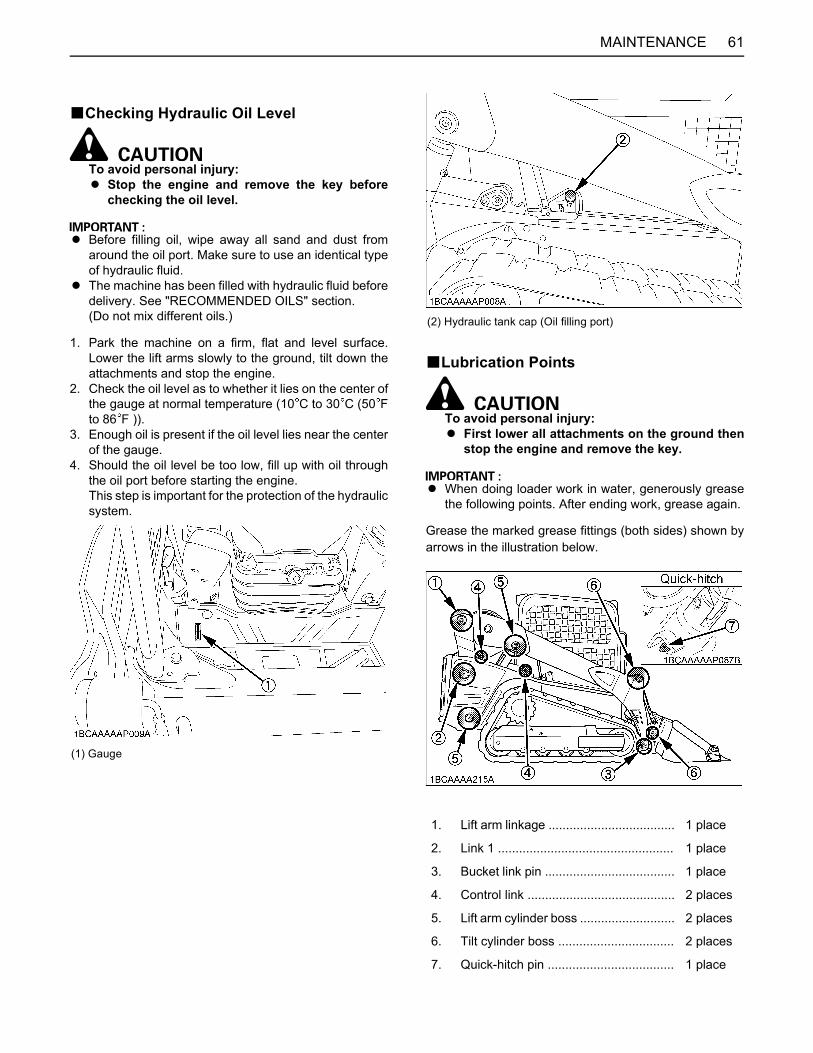
61MAINTENANCE
BChecking Hydraulic Oil Level
To avoid personal injury:A Stop the engine and remove the key before
checking the oil level.
A Before filling oil, wipe away all sand and dust fromaround the oil port. Make sure to use an identical typeof hydraulic fluid.
A The machine has been filled with hydraulic fluid beforedelivery. See "RECOMMENDED OILS" section.(Do not mix different oils.)
1. Park the machine on a firm, flat and level surface.Lower the lift arms slowly to the ground, tilt down theattachments and stop the engine.
2. Check the oil level as to whether it lies on the center ofthe gauge at normal temperature (10 C to 30 C (50 Fto 86 F )).
3. Enough oil is present if the oil level lies near the centerof the gauge.
4. Should the oil level be too low, fill up with oil throughthe oil port before starting the engine.This step is important for the protection of the hydraulicsystem.
BLubrication Points
To avoid personal injury:A First lower all attachments on the ground then
stop the engine and remove the key.
A When doing loader work in water, generously greasethe following points. After ending work, grease again.
Grease the marked grease fittings (both sides) shown byarrows in the illustration below.
(1) Gauge
(2) Hydraulic tank cap (Oil filling port)
1. Lift arm linkage .................................... 1 place
2. Link 1 .................................................. 1 place
3. Bucket link pin ..................................... 1 place
4. Control link .......................................... 2 places
5. Lift arm cylinder boss ........................... 2 places
6. Tilt cylinder boss ................................. 2 places
7. Quick-hitch pin .................................... 1 place
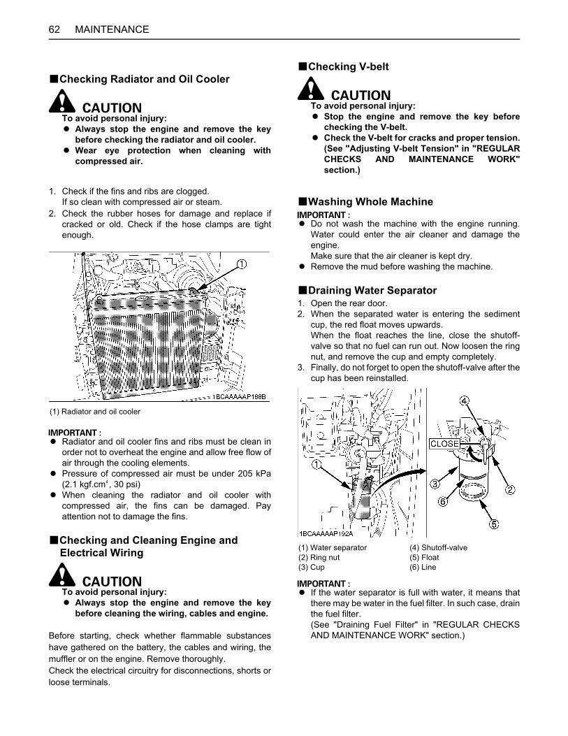
MAINTENANCE62
BChecking Radiator and Oil Cooler
To avoid personal injury:A Always stop the engine and remove the key
before checking the radiator and oil cooler.A Wear eye protection when cleaning with
compressed air.
1. Check if the fins and ribs are clogged.If so clean with compressed air or steam.
2. Check the rubber hoses for damage and replace ifcracked or old. Check if the hose clamps are tightenough.
A Radiator and oil cooler fins and ribs must be clean inorder not to overheat the engine and allow free flow ofair through the cooling elements.
A Pressure of compressed air must be under 205 kPa(2.1 kgf.cm , 30 psi)
A When cleaning the radiator and oil cooler withcompressed air, the fins can be damaged. Payattention not to damage the fins.
BChecking and Cleaning Engine and Electrical Wiring
To avoid personal injury:A Always stop the engine and remove the key
before cleaning the wiring, cables and engine.
Before starting, check whether flammable substanceshave gathered on the battery, the cables and wiring, themuffler or on the engine. Remove thoroughly.Check the electrical circuitry for disconnections, shorts orloose terminals.
BChecking V-belt
To avoid personal injury:A Stop the engine and remove the key before
checking the V-belt.A Check the V-belt for cracks and proper tension.
(See "Adjusting V-belt Tension" in "REGULARCHECKS AND MAINTENANCE WORK"section.)
BWashing Whole Machine
A Do not wash the machine with the engine running.Water could enter the air cleaner and damage theengine.Make sure that the air cleaner is kept dry.
A Remove the mud before washing the machine.
BDraining Water Separator1. Open the rear door.2. When the separated water is entering the sediment
cup, the red float moves upwards.When the float reaches the line, close the shutoff-valve so that no fuel can run out. Now loosen the ringnut, and remove the cup and empty completely.
3. Finally, do not forget to open the shutoff-valve after thecup has been reinstalled.
A If the water separator is full with water, it means thatthere may be water in the fuel filter. In such case, drainthe fuel filter.(See "Draining Fuel Filter" in "REGULAR CHECKSAND MAINTENANCE WORK" section.)
(1) Radiator and oil cooler
(1) Water separator(2) Ring nut(3) Cup
(4) Shutoff-valve(5) Float(6) Line
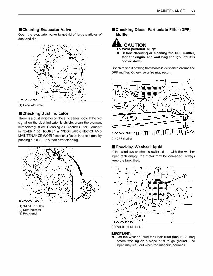
63MAINTENANCE
BCleaning Evacuator ValveOpen the evacuator valve to get rid of large particles ofdust and dirt.
BChecking Dust IndicatorThere is a dust indicator on the air cleaner body. If the redsignal on the dust indicator is visible, clean the elementimmediately. (See "Cleaning Air Cleaner Outer Element"in "EVERY 50 HOURS" in "REGULAR CHECKS ANDMAINTENANCE WORK" section.) Reset the red signal bypushing a "RESET" button after cleaning.
BChecking Diesel Particulate Filter (DPF) Muffler
To avoid personal injury:A Before checking or cleaning the DPF muffler,
stop the engine and wait long enough until it iscooled down.
Check to see if nothing flammable is deposited around theDPF muffler. Otherwise a fire may result.
BChecking Washer LiquidIf the windows washer is switched on with the washerliquid tank empty, the motor may be damaged. Alwayskeep the tank filled.
A Get the washer liquid tank half filled (about 0.8 liter)before working on a slope or a rough ground. Theliquid may leak out when the machine bounces.
(1) Evacuator valve
(1) "RESET" button(2) Dust indicator(3) Red signal
(1) DPF muffler
(1) Washer liquid tank

MAINTENANCE64
BChecking Battery Condition
To avoid the possibility of a battery explosion:For refillable type battery, follow the instructionsbelow.A Do not use or charge the refillable type battery
if the fluid level is below the LOWER (lower limitlevel) mark. Otherwise, the battery componentparts may prematurely deteriorate, which mayshorten the battery's service life or cause anexplosion. Check the fluid level regularly andadd distilled water as required so that the fluidlevel is between the UPPER and LOWER levels.
To avoid personal injury:A Never remove the vent caps while the engine is
running.A Keep electrolyte away from eyes, hands and
clothes. If you are spattered with it, wash itaway completely with water immediately andget medical attention.
A Wear eye protection and rubber gloves whenworking around the battery.
A Before inspection or dismounting the battery,be sure to turn off the engine and turn thestarter switch to the "OFF" position.
A When removing the battery, always disconnectthe negative ground cable first. When installinga battery, always connect the ground cablelast. This prevents a possible explosion causedby sparks.
A Always wear eye protection when working withthe battery.
Mishandling the battery shortens the service life and addsto maintenance costs.The original battery is maintenance free, but needs someservicing.If the battery is weak, the engine will be difficult to startand the lights will be dim. It is important to check thebattery periodically.
C How to read the indicatorCheck the battery condition by reading the indicator.
The factory-installed battery is of non-refillable type.If the indicator turns white, do not quick charge thebattery but replace it with new one.
(1) Battery(2) Indicator
State of indicator display
Green Specific gravity of electrolyte and quality of electrolyte are both in good condition.
Black Needs charging battery.
White Needs replacing battery.
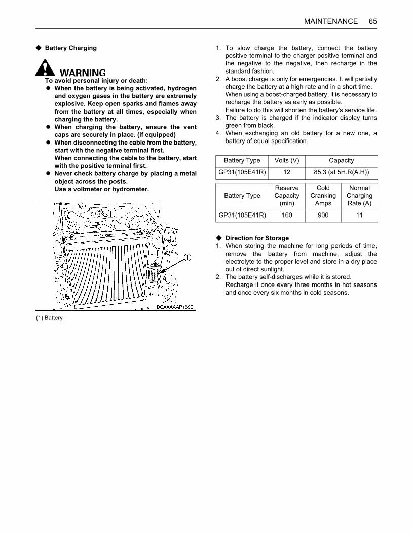
65MAINTENANCE
C Battery Charging
To avoid personal injury or death: A When the battery is being activated, hydrogen
and oxygen gases in the battery are extremelyexplosive. Keep open sparks and flames awayfrom the battery at all times, especially whencharging the battery.
A When charging the battery, ensure the ventcaps are securely in place. (if equipped)
A When disconnecting the cable from the battery,start with the negative terminal first.When connecting the cable to the battery, startwith the positive terminal first.
A Never check battery charge by placing a metalobject across the posts.Use a voltmeter or hydrometer.
1. To slow charge the battery, connect the batterypositive terminal to the charger positive terminal andthe negative to the negative, then recharge in thestandard fashion.
2. A boost charge is only for emergencies. It will partiallycharge the battery at a high rate and in a short time.When using a boost-charged battery, it is necessary torecharge the battery as early as possible.Failure to do this will shorten the battery's service life.
3. The battery is charged if the indicator display turnsgreen from black.
4. When exchanging an old battery for a new one, abattery of equal specification.
C Direction for Storage1. When storing the machine for long periods of time,
remove the battery from machine, adjust theelectrolyte to the proper level and store in a dry placeout of direct sunlight.
2. The battery self-discharges while it is stored.Recharge it once every three months in hot seasonsand once every six months in cold seasons.
(1) Battery
Battery Type Volts (V) Capacity
GP31(105E41R) 12 85.3 (at 5H.R(A.H))
Battery TypeReserve Capacity
(min)
Cold Cranking
Amps
NormalChargingRate (A)
GP31(105E41R) 160 900 11
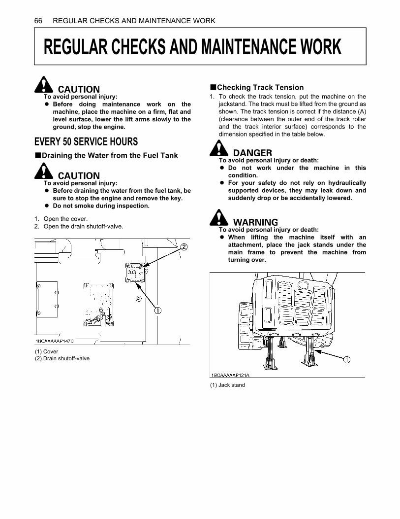
66 REGULAR CHECKS AND MAINTENANCE WORK
REGULAR CHECKS AND MAINTENANCE WORK
To avoid personal injury:A Before doing maintenance work on the
machine, place the machine on a firm, flat andlevel surface, lower the lift arms slowly to theground, stop the engine.
EVERY 50 SERVICE HOURSBDraining the Water from the Fuel Tank
To avoid personal injury:A Before draining the water from the fuel tank, be
sure to stop the engine and remove the key.A Do not smoke during inspection.
1. Open the cover.2. Open the drain shutoff-valve.
BChecking Track Tension1. To check the track tension, put the machine on the
jackstand. The track must be lifted from the ground asshown. The track tension is correct if the distance (A)(clearance between the outer end of the track rollerand the track interior surface) corresponds to thedimension specified in the table below.
To avoid personal injury or death:A Do not work under the machine in this
condition.A For your safety do not rely on hydraulically
supported devices, they may leak down andsuddenly drop or be accidentally lowered.
To avoid personal injury or death:A When lifting the machine itself with an
attachment, place the jack stands under themain frame to prevent the machine fromturning over.
(1) Cover(2) Drain shutoff-valve
(1) Jack stand

67REGULAR CHECKS AND MAINTENANCE WORK
2. If necessary, adjust the tension.
A Make sure that no obstacles, such as stones arecaught in the track. Remove such obstacles beforeadjusting the track tension. (See "ADJUSTMENT OFTRACKS" in "OTHER ADJUSTMENTS ANDREPLACEMENTS" section.)
BInspection and Cleaning Air Cleaner Element
Open the rear door and remove the dust-cover. Take outonly outer element, clean the element, case interior andreassemble. During reassembly, take care to install thedust-cover so that its TOP mark (arrow) faces up-wards.Do not remove the inner element.
A Should the machine be used in extremely dusty areas,the air cleaner element must be inspected andcleaned more frequently than in the specifiedmaintenance periods.
A The air cleaner has a dry element, keep free from oil. A Do not run the engine without the air cleaner.
(1) Drive sprocket(2) Idler
(A) 20 to 30 mm (0.8 to 1.2 in.)
(1) Inner element (2) Outer element (3) Dust-cover(4) Clamps
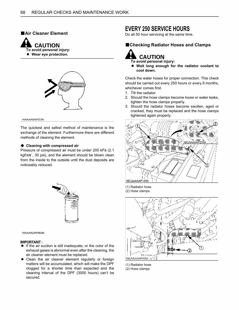
REGULAR CHECKS AND MAINTENANCE WORK68
BAir Cleaner Element
To avoid personal injury:A Wear eye protection.
The quickest and safest method of maintenance is theexchange of the element. Furthermore there are differentmethods of cleaning the element.
C Cleaning with compressed airPressure of compressed air must be under 205 kPa (2.1kgf/ , 30 psi), and the element should be blown cleanfrom the inside to the outside until the dust deposits arenoticeably reduced.
A If the air suction is still inadequate, or the color of theexhaust gases is abnormal even after the cleaning, theair cleaner element must be replaced.
A Clean the air cleaner element regularly or foreignmatters will be accumulated, which will make the DPFclogged for a shorter time than expected and thecleaning interval of the DPF (3000 hours) can’t besecured.
EVERY 250 SERVICE HOURSDo all 50 hour servicing at the same time.
BChecking Radiator Hoses and Clamps
To avoid personal injury:A Wait long enough for the radiator coolant to
cool down.
Check the water hoses for proper connection. This checkshould be carried out every 250 hours or every 6 months,whichever comes first.1. Tilt the radiator.2. Should the hose clamps become loose or water leaks,
tighten the hose clamps properly.3. Should the radiator hoses become swollen, aged or
cracked, they must be replaced and the hose clampstightened again properly.
(1) Radiator hose(2) Hose clamps
(1) Radiator hose(2) Hose clamps
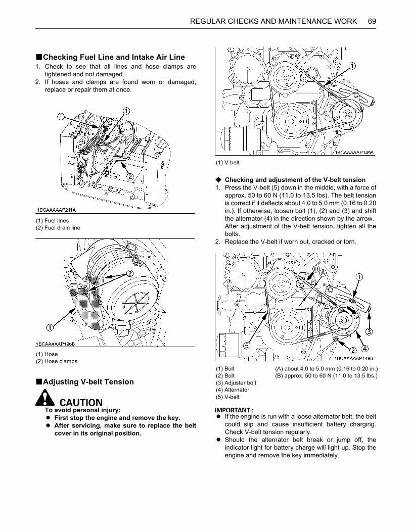
69REGULAR CHECKS AND MAINTENANCE WORK
BChecking Fuel Line and Intake Air Line1. Check to see that all lines and hose clamps are
tightened and not damaged.2. If hoses and clamps are found worn or damaged,
replace or repair them at once.
BAdjusting V-belt Tension
To avoid personal injury:A First stop the engine and remove the key.A After servicing, make sure to replace the belt
cover in its original position.
C Checking and adjustment of the V-belt tension1. Press the V-belt (5) down in the middle, with a force of
approx. 50 to 60 N (11.0 to 13.5 lbs). The belt tensionis correct if it deflects about 4.0 to 5.0 mm (0.16 to 0.20in.). If otherwise, loosen bolt (1), (2) and (3) and shiftthe alternator (4) in the direction shown by the arrow. After adjustment of the V-belt tension, tighten all thebolts.
2. Replace the V-belt if worn out, cracked or torn.
A If the engine is run with a loose alternator belt, the beltcould slip and cause insufficient battery charging.Check V-belt tension regularly.
A Should the alternator belt break or jump off, theindicator light for battery charge will light up. Stop theengine and remove the key immediately.
(1) Fuel lines(2) Fuel drain line
(1) Hose(2) Hose clamps
(1) V-belt
(1) Bolt(2) Bolt(3) Adjuster bolt(4) Alternator(5) V-belt
(A) about 4.0 to 5.0 mm (0.16 to 0.20 in.)(B) approx. 50 to 60 N (11.0 to 13.5 lbs.)

REGULAR CHECKS AND MAINTENANCE WORK70
C Checking and adjustment of the air-conditionerbelt tension [Closed cab model]
1. Press the air-conditioner belt down in the middle, witha force of approx. 50 to 60 N (11.0 to 13.5 lbs). Thebelt tension is correct if it deflects about 7 to 9 mm(0.27 to 0.35 in.). If otherwise, loosen bolt of thetension pulley and shift the tension pulley in thedirection shown by the arrow.
2. Replace the air-conditioner belt if worn out, cracked ortorn.
BCleaning Inside of Main FrameIf mud, leaves or any debris are accumulated inside ofmain frame, it may cause any parts damaged.Remove mud, leaves and any debris from the inside of theframe.Refer to page 59 for detail procedure.
BReplacing Air Cleaner ElementOpen the rear door and engine hood. Remove the dust-cover. Remove and replace the outer element and innerelement with new elements.When reassembling, install the dust-cover so that its TOPmark (arrow) faces up-wards.
A Shorten the replacement period if the machine is usedin dusty or sandy areas.
A Replace the air cleaner element regularly or foreignmatters will be accumulated, which will make the DPFclogged for a shorter time than expected and thecleaning interval of the DPF (3000 hours) can’t besecured.
BCleaning Inner Air FilterRemove the inner filter, and blow air from the directionopposite to the filter's normal air flow.Pressure of compressed air must be under 205 kPa (2.1kgf/cm , 30 psi).
(1) Air-conditioner belt(2) Tension pulley(3) Air-conditioner compressor(4) Pulley(5) Bolt
(A) about 7 to 9 mm (0.27 to 0.35 in.)(B) approx. 50 to 60 N (11.0 to 13.5 lbs.)
(1) Plate
(1) Inner element(2) Outer element(3) Dust-cover(4) Clamps
(1) Inner air filter
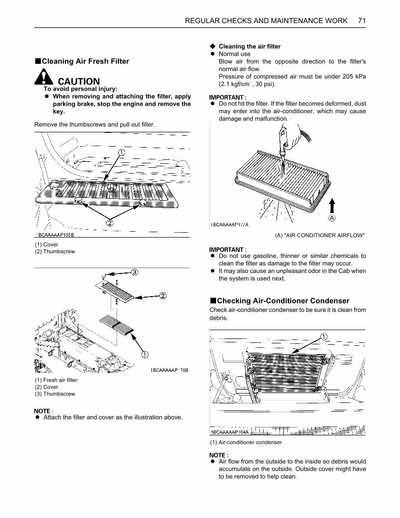
71REGULAR CHECKS AND MAINTENANCE WORK
BCleaning Air Fresh Filter
To avoid personal injury:A When removing and attaching the filter, apply
parking brake, stop the engine and remove thekey.
Remove the thumbscrews and pull out filter.
A Attach the filter and cover as the illustration above.
C Cleaning the air filterA Normal use
Blow air from the opposite direction to the filter'snormal air flow.Pressure of compressed air must be under 205 kPa(2.1 kgf/cm , 30 psi).
A Do not hit the filter. If the filter becomes deformed, dustmay enter into the air-conditioner, which may causedamage and malfunction.
A Do not use gasoline, thinner or similar chemicals toclean the filter as damage to the filter may occur.
A It may also cause an unpleasant odor in the Cab whenthe system is used next.
BChecking Air-Conditioner CondenserCheck air-conditioner condenser to be sure it is clean fromdebris.
A Air flow from the outside to the inside so debris wouldaccumulate on the outside. Outside cover might haveto be removed to help clean.
(1) Cover(2) Thumbscrew
(1) Fresh air filter(2) Cover(3) Thumbscrew
(A) "AIR CONDITIONER AIRFLOW"
(1) Air-conditioner condenser

REGULAR CHECKS AND MAINTENANCE WORK72
EVERY 500 SERVICE HOURSDo all 50 and 250 hour servicing at the same time.
BChanging Engine Oil
To avoid personal injury:A First stop the engine then remove the key and
wait long enough for the oil to cool down.
1. Remove the under cover on the bottom of the frame.2. Remove the drain plug on the underside of the engine
and drain all oil.3. Re-tighten the drain plug, and attach the under cover.
4. Fill up with new oil through the filling port to thespecified level.
BReplacing Engine Oil Filter Cartridge1. Remove the under cover on the bottom of the frame (to
drain the spilled oil from the engine oil filter cartridge).
2. Replace the oil filter cartridge at the same time asdoing the engine oil change.
3. Remove the cartridge with the filter wrench.
4. Oil the O-ring of the new oil filter cartridge lightly. Thentighten the oil filter cartridge by hand.
5. Fill engine oil to the specified level.6. Let the engine run for approx. 5 min. and make sure
that the engine oil indicator lamp does not light up.Then stop the engine and remove the key.
7. The engine oil level is reduced by the amount of thefilter capacity after the engine is started. It is necessaryto add oil.
8. Attach the under cover.
A Always check the oil level after having exchanged thefilter.
(1) Drain plug(2) Under cover
(1) Oil filling port(2) Engine oil dipstick
(A) Required oil level range
Engine oil volumes(with engine oil filter) 11 L (2.9 US gal)
(1) Under cover
(1) Oil filter cartridge
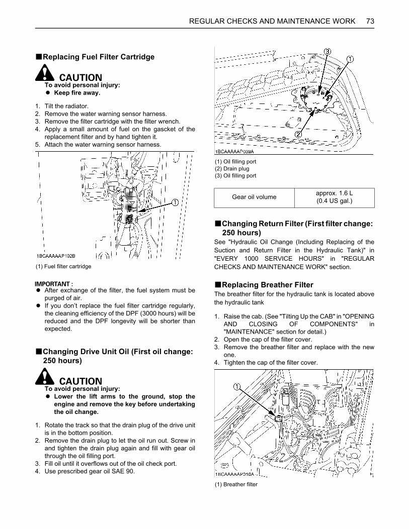
73REGULAR CHECKS AND MAINTENANCE WORK
BReplacing Fuel Filter Cartridge
To avoid personal injury:A Keep fire away.
1. Tilt the radiator.2. Remove the water warning sensor harness.3. Remove the filter cartridge with the filter wrench.4. Apply a small amount of fuel on the gascket of the
replacement filter and by hand tighten it.5. Attach the water warning sensor harness.
A After exchange of the filter, the fuel system must bepurged of air.
A If you don’t replace the fuel filter cartridge regularly,the cleaning efficiency of the DPF (3000 hours) will bereduced and the DPF longevity will be shorter thanexpected.
BChanging Drive Unit Oil (First oil change: 250 hours)
To avoid personal injury:A Lower the lift arms to the ground, stop the
engine and remove the key before undertakingthe oil change.
1. Rotate the track so that the drain plug of the drive unitis in the bottom position.
2. Remove the drain plug to let the oil run out. Screw inand tighten the drain plug again and fill with gear oilthrough the oil filling port.
3. Fill oil until it overflows out of the oil check port.4. Use prescribed gear oil SAE 90.
BChanging Return Filter (First filter change: 250 hours)
See "Hydraulic Oil Change (Including Replacing of theSuction and Return Filter in the Hydraulic Tank)" in"EVERY 1000 SERVICE HOURS" in "REGULARCHECKS AND MAINTENANCE WORK" section.
BReplacing Breather FilterThe breather filter for the hydraulic tank is located abovethe hydraulic tank
1. Raise the cab. (See "Tilting Up the CAB" in "OPENINGAND CLOSING OF COMPONENTS" in"MAINTENANCE" section for detail.)
2. Open the cap of the filter cover.3. Remove the breather filter and replace with the new
one.4. Tighten the cap of the filter cover.
(1) Fuel filter cartridge
(1) Oil filling port(2) Drain plug(3) Oil filling port
Gear oil volume approx. 1.6 L(0.4 US gal.)
(1) Breather filter
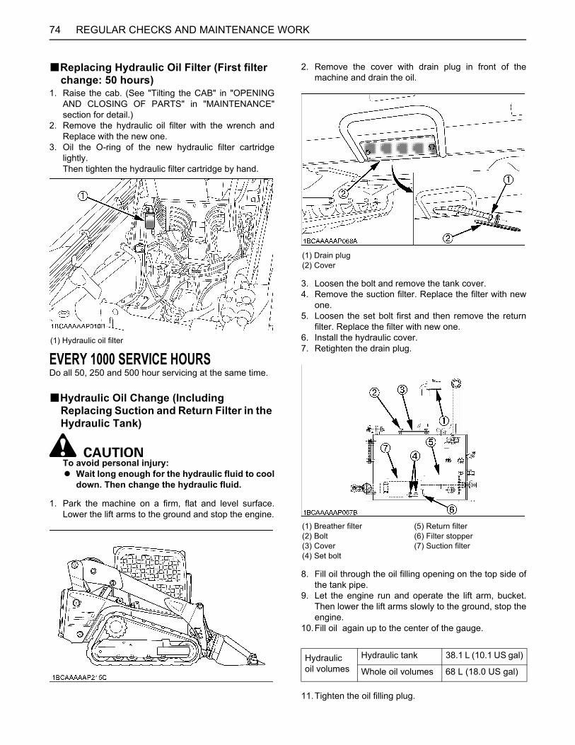
REGULAR CHECKS AND MAINTENANCE WORK74
BReplacing Hydraulic Oil Filter (First filter change: 50 hours)
1. Raise the cab. (See "Tilting the CAB" in "OPENINGAND CLOSING OF PARTS" in "MAINTENANCE"section for detail.)
2. Remove the hydraulic oil filter with the wrench andReplace with the new one.
3. Oil the O-ring of the new hydraulic filter cartridgelightly.Then tighten the hydraulic filter cartridge by hand.
EVERY 1000 SERVICE HOURSDo all 50, 250 and 500 hour servicing at the same time.
BHydraulic Oil Change (Including Replacing Suction and Return Filter in the Hydraulic Tank)
To avoid personal injury: A Wait long enough for the hydraulic fluid to cool
down. Then change the hydraulic fluid.
1. Park the machine on a firm, flat and level surface.Lower the lift arms to the ground and stop the engine.
2. Remove the cover with drain plug in front of themachine and drain the oil.
3. Loosen the bolt and remove the tank cover.4. Remove the suction filter. Replace the filter with new
one.5. Loosen the set bolt first and then remove the return
filter. Replace the filter with new one.6. Install the hydraulic cover.7. Retighten the drain plug.
8. Fill oil through the oil filling opening on the top side ofthe tank pipe.
9. Let the engine run and operate the lift arm, bucket.Then lower the lift arms slowly to the ground, stop theengine.
10.Fill oil again up to the center of the gauge.
11.Tighten the oil filling plug.
(1) Hydraulic oil filter
(1) Drain plug(2) Cover
(1) Breather filter(2) Bolt(3) Cover(4) Set bolt
(5) Return filter(6) Filter stopper(7) Suction filter
Hydraulic oil volumes
Hydraulic tank 38.1 L (10.1 US gal)
Whole oil volumes 68 L (18.0 US gal)
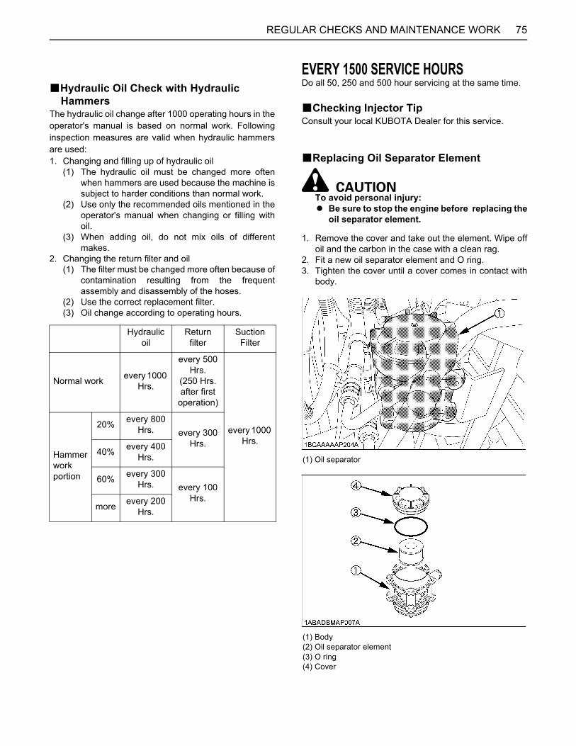
75REGULAR CHECKS AND MAINTENANCE WORK
BHydraulic Oil Check with Hydraulic Hammers
The hydraulic oil change after 1000 operating hours in theoperator's manual is based on normal work. Followinginspection measures are valid when hydraulic hammersare used: 1. Changing and filling up of hydraulic oil
(1) The hydraulic oil must be changed more oftenwhen hammers are used because the machine issubject to harder conditions than normal work.
(2) Use only the recommended oils mentioned in theoperator's manual when changing or filling withoil.
(3) When adding oil, do not mix oils of differentmakes.
2. Changing the return filter and oil(1) The filter must be changed more often because of
contamination resulting from the frequentassembly and disassembly of the hoses.
(2) Use the correct replacement filter. (3) Oil change according to operating hours.
EVERY 1500 SERVICE HOURSDo all 50, 250 and 500 hour servicing at the same time.
BChecking Injector TipConsult your local KUBOTA Dealer for this service.
BReplacing Oil Separator Element
To avoid personal injury:A Be sure to stop the engine before replacing the
oil separator element.
1. Remove the cover and take out the element. Wipe offoil and the carbon in the case with a clean rag.
2. Fit a new oil separator element and O ring.3. Tighten the cover until a cover comes in contact with
body.
Hydraulic oil
Return filter
Suction Filter
Normal work every 1000 Hrs.
every 500 Hrs.
(250 Hrs. after first
operation)
every 1000 Hrs.
Hammerworkportion
20% every 800 Hrs. every 300
Hrs.40% every 400
Hrs.
60% every 300 Hrs. every 100
Hrs.more every 200
Hrs.
(1) Oil separator
(1) Body(2) Oil separator element(3) O ring(4) Cover
REGULAR CHECKS AND MAINTENANCE WORK76
BChecking PCV (Positive Crankcase Ventilation) Valve
Consult your local KUBOTA Dealer for this service.
BChecking EGR CoolerConsult your local KUBOTA Dealer for this service.
EVERY 2000 SERVICE HOURSDo all 50, 250, 500 and 1000 hour servicing at the sametime.
BChecking the Alternator and Starter Motor
A Contact your KUBOTA dealer for details.
EVERY 3000 SERVICE HOURSDo all 50, 250, 500, 1000 and 1500 hour servicing at thesame time.
BChecking EGR SystemConsult your local KUBOTA Dealer for this service.
BChecking TurbochargerConsult your local KUBOTA Dealer for this service.
BCleaning Diesel Particulate Filter (DPF)The longer the DPF operates, the more ash (burntresidue) is collected in the filter. Too much ash build-upadversely affects the DPF performance. Consult yourlocal KUBOTA Dealer to clean up the filter.
A To clean up the DPF, a specific machine is required.Do not attempt to clean it in any other way, such asdisassembling, shaking and heating as toxicchemicals may be present inside of the DPF.
ANNUAL SERVICINGBChecking Air-Conditioner Pipes and
Hoses
To avoid personal injury:A Do not touch the air-conditioner hoses or the
heater with your hand. You may get burned.
1. Check to see that all lines and hose clamps are tightand not damaged.
2. If hoses and clamps are found worn or damaged,replace or repair them at once. (Consult your localKUBOTA Dealer for this service.)
BChecking Exhaust Manifold (Cracks, Gas, Leakage and Mounting Screw)
Consult your local KUBOTA Dealer for this service.
BChecking Intake Air Line for Air LeaksConsult your local KUBOTA Dealer for this service.
BChecking Boost Sensor and AFS (Air Flow Sensor)
Consult your local KUBOTA Dealer for this service.
BChecking Condition of Diesel Particulate Filter (DPF) Muffler
Consult your local KUBOTA Dealer for this service.
BChecking Diesel Particulate Filter (DPF) Differential Pressure Sensor and Piping for Gas Leak
Consult your local KUBOTA Dealer for this service.
BChecking Diesel Particulate Filter (DPF) Exhaust Gas Temperature Sensor
Consult your local KUBOTA Dealer for this service.
BChecking EGR Piping for Gas LeakConsult your local KUBOTA Dealer for this service.

77REGULAR CHECKS AND MAINTENANCE WORK
BIENNIAL SERVICINGBChanging Radiator Coolant
To avoid personal injury:A When using anti-freeze, use protective clothing
such as rubber gloves (Anti-freeze containspoison.).
A If anti-freeze has been swallowed, seek medicalattention at once.
A When anti-freeze comes in contact with theskin or clothing, wash it off immediately.
A Do not mix different types of Anti-freeze. Themixture can produce a chemical reactioncausing harmful substances or vapors.
A Anti-freeze is extremely flammable andexplosive under certain conditions. Keep fireand children away from anti-freeze.
A When draining fluids from the engine, collectsuch with a some container underneath theengine body.
A Do not pour waste onto the grounds, down adrain, or into any water source.
A Also, observe the relevant environmentalprotection regulations when disposing of anti-freeze.
A Anti-freeze if swallowed is poisonous topeople, animals and birds.
Park the machine on a firm, flat and level surface, lowerthe lift arms to the ground and stop the engine thenremove the key and wait until it has cooled downcompletely.1. Tilt the radiator.2. Open the drain plug on the bottom of the radiator and
drain coolant completely, Should a recovery tank beequipped, disconnect the line from the tank floor andthen open the drain shutoff-valve.
3. To clean, rinse the radiator with water.4. Close the drain plug and fill the radiator and the
recovery tank with coolant fluid. Let the engine idle forabout 5 min., stop the engine and remove the key.
5. Check the coolant level of recovery tank and add thecoolant if necessary.
6. The machine has been shipped filled with 50% anti-freeze solution.
(1) Drain plug(2) Radiator cap
(1) Drain plug
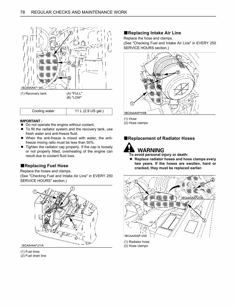
REGULAR CHECKS AND MAINTENANCE WORK78
A Do not operate the engine without coolant. A To fill the radiator system and the recovery tank, use
fresh water and anti-freeze fluid. A When the anti-freeze is mixed with water, the anti-
freeze mixing ratio must be less than 50%.A Tighten the radiator cap properly. If the cap is loosely
or not properly fitted, overheating of the engine canresult due to coolant fluid loss.
BReplacing Fuel HoseReplace the hoses and clamps.(See "Checking Fuel and Intake Air Line" in EVERY 250SERVICE HOURS" section.)
BReplacing Intake Air LineReplace the hose and clamps.(See "Checking Fuel and Intake Air Line" in EVERY 250SERVICE HOURS section.)
BReplacement of Radiator Hoses
To avoid personal injury or death:A Replace radiator hoses and hose clamps every
two years. If the hoses are swollen, hard orcracked, they must be replaced earlier.
(1) Recovery tank (A) "FULL"(B) "LOW"
Cooling water 11 L (2.9 US gal.)
(1) Fuel lines(2) Fuel drain line
(1) Hose(2) Hose clamps
(1) Radiator hose(2) Hose clamps
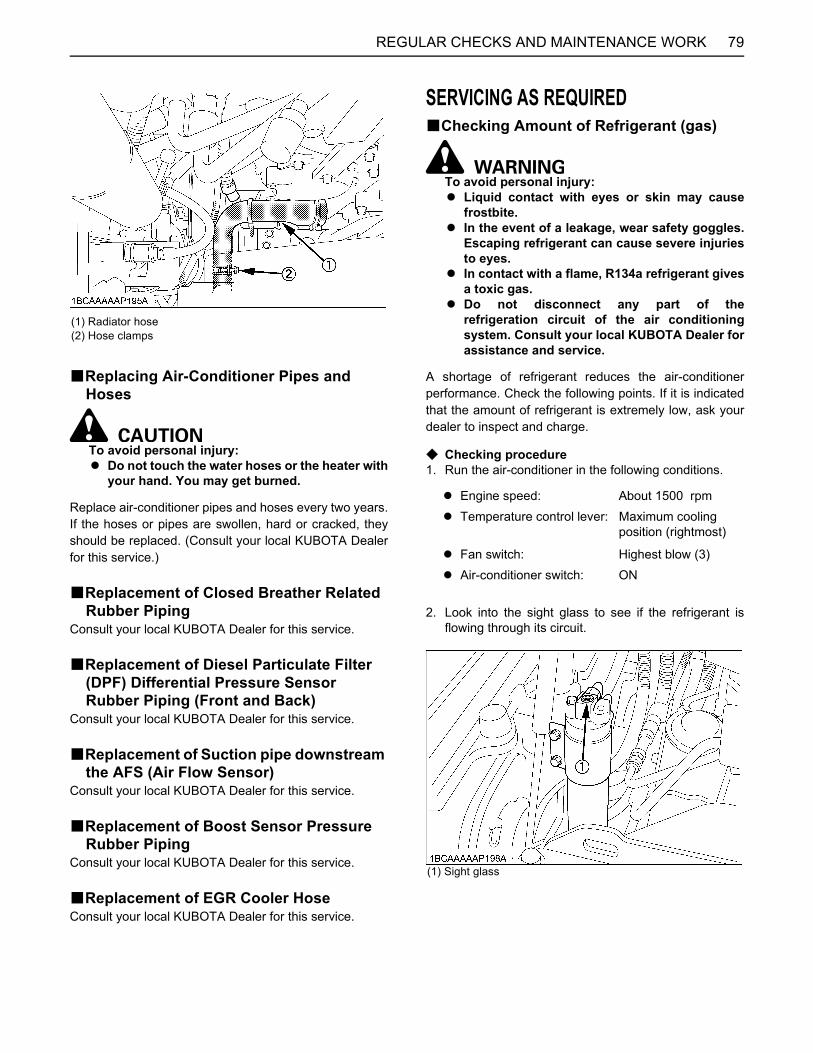
79REGULAR CHECKS AND MAINTENANCE WORK
BReplacing Air-Conditioner Pipes and Hoses
To avoid personal injury:A Do not touch the water hoses or the heater with
your hand. You may get burned.
Replace air-conditioner pipes and hoses every two years.If the hoses or pipes are swollen, hard or cracked, theyshould be replaced. (Consult your local KUBOTA Dealerfor this service.)
BReplacement of Closed Breather Related Rubber Piping
Consult your local KUBOTA Dealer for this service.
BReplacement of Diesel Particulate Filter (DPF) Differential Pressure Sensor Rubber Piping (Front and Back)
Consult your local KUBOTA Dealer for this service.
BReplacement of Suction pipe downstream the AFS (Air Flow Sensor)
Consult your local KUBOTA Dealer for this service.
BReplacement of Boost Sensor Pressure Rubber Piping
Consult your local KUBOTA Dealer for this service.
BReplacement of EGR Cooler HoseConsult your local KUBOTA Dealer for this service.
SERVICING AS REQUIREDBChecking Amount of Refrigerant (gas)
To avoid personal injury:A Liquid contact with eyes or skin may cause
frostbite.A In the event of a leakage, wear safety goggles.
Escaping refrigerant can cause severe injuriesto eyes.
A In contact with a flame, R134a refrigerant givesa toxic gas.
A Do not disconnect any part of therefrigeration circuit of the air conditioningsystem. Consult your local KUBOTA Dealer forassistance and service.
A shortage of refrigerant reduces the air-conditionerperformance. Check the following points. If it is indicatedthat the amount of refrigerant is extremely low, ask yourdealer to inspect and charge.
C Checking procedure1. Run the air-conditioner in the following conditions.
2. Look into the sight glass to see if the refrigerant isflowing through its circuit.
(1) Radiator hose(2) Hose clamps
A Engine speed: About 1500 rpmA Temperature control lever: Maximum cooling
position (rightmost)
A Fan switch: Highest blow (3)A Air-conditioner switch: ON
(1) Sight glass
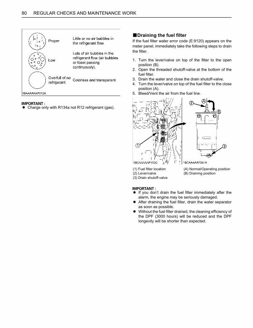
REGULAR CHECKS AND MAINTENANCE WORK80
A Charge only with R134a not R12 refrigerant (gas).
BDraining the fuel filterIf the fuel filter water error code (E:9120) appears on themeter panel, immediately take the following steps to drainthe filter.
1. Turn the lever/valve on top of the filter to the openposition (B).
2. Open the threaded shutoff-valve at the bottom of thefuel filter.
3. Drain the water and close the drain shutoff-valve.4. Turn the lever/valve on top of the fuel filter to the close
position (A).5. Bleed/Vent the air from the fuel line.
A If you don’t drain the fuel filter immediately after thealarm, the engine may be seriously damaged.
A After draining the fuel filter, drain the water separatoras soon as possible.
A Without the fuel filter drained, the cleaning efficiency ofthe DPF (3000 hours) will be reduced and the DPFlongevity will be shorter than expected.
(1) Fuel filter location(2) Lever/valve(3) Drain shutoff-valve
(A) Normal/Operating position(B) Draining position
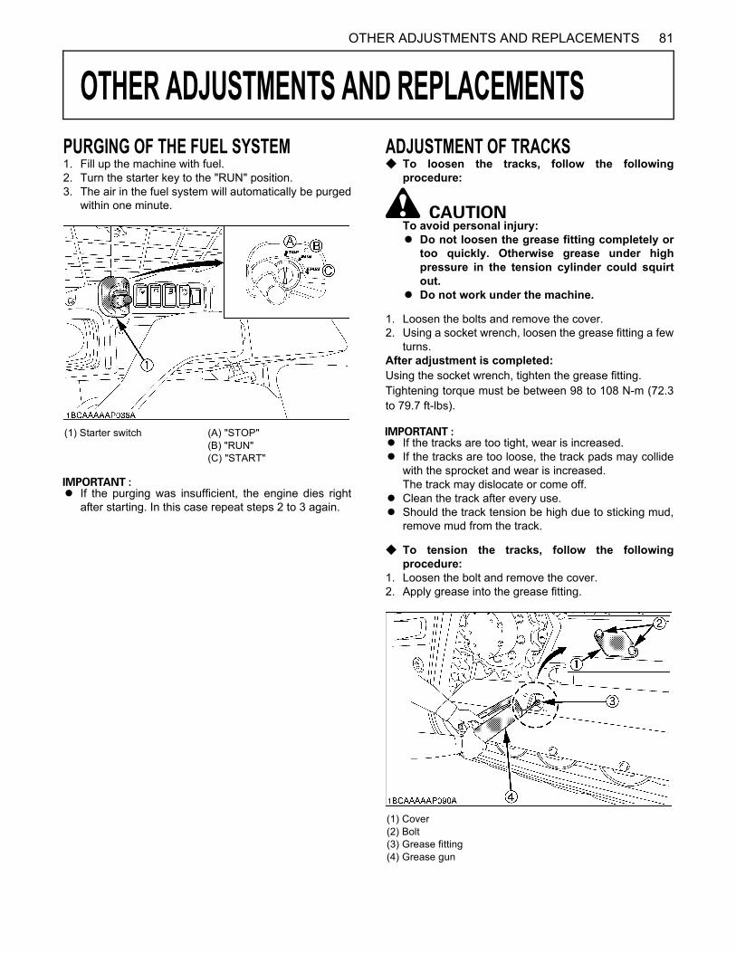
81OTHER ADJUSTMENTS AND REPLACEMENTS
OTHER ADJUSTMENTS AND REPLACEMENTS
PURGING OF THE FUEL SYSTEM1. Fill up the machine with fuel. 2. Turn the starter key to the "RUN" position.3. The air in the fuel system will automatically be purgedwithin one minute.
A If the purging was insufficient, the engine dies rightafter starting. In this case repeat steps 2 to 3 again.
ADJUSTMENT OF TRACKSC To loosen the tracks, follow the following
procedure:
To avoid personal injury: A Do not loosen the grease fitting completely or
too quickly. Otherwise grease under highpressure in the tension cylinder could squirtout.
A Do not work under the machine.
1. Loosen the bolts and remove the cover.2. Using a socket wrench, loosen the grease fitting a few
turns.After adjustment is completed:Using the socket wrench, tighten the grease fitting.Tightening torque must be between 98 to 108 N-m (72.3to 79.7 ft-lbs).
A If the tracks are too tight, wear is increased. A If the tracks are too loose, the track pads may collide
with the sprocket and wear is increased.The track may dislocate or come off.
A Clean the track after every use. A Should the track tension be high due to sticking mud,
remove mud from the track.
C To tension the tracks, follow the followingprocedure:
1. Loosen the bolt and remove the cover. 2. Apply grease into the grease fitting.
(1) Starter switch (A) "STOP"(B) "RUN"(C) "START"
(1) Cover(2) Bolt(3) Grease fitting(4) Grease gun
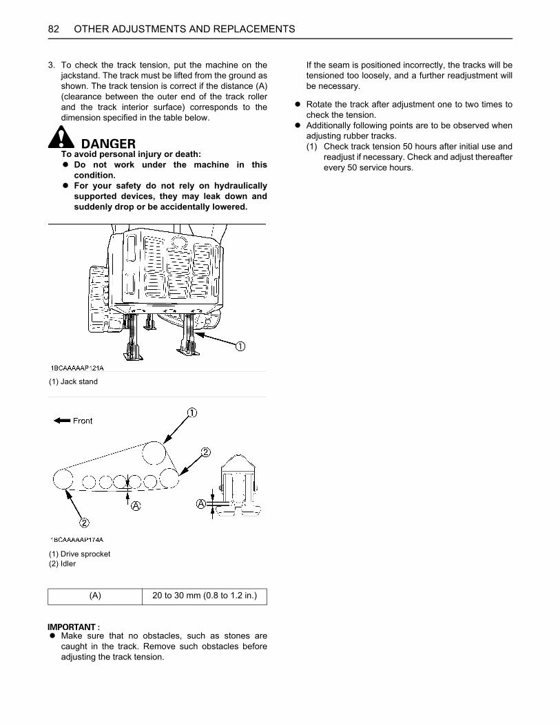
OTHER ADJUSTMENTS AND REPLACEMENTS82
3. To check the track tension, put the machine on thejackstand. The track must be lifted from the ground asshown. The track tension is correct if the distance (A)(clearance between the outer end of the track rollerand the track interior surface) corresponds to thedimension specified in the table below.
To avoid personal injury or death:A Do not work under the machine in this
condition.A For your safety do not rely on hydraulically
supported devices, they may leak down andsuddenly drop or be accidentally lowered.
A Make sure that no obstacles, such as stones arecaught in the track. Remove such obstacles beforeadjusting the track tension.
If the seam is positioned incorrectly, the tracks will betensioned too loosely, and a further readjustment willbe necessary.
A Rotate the track after adjustment one to two times tocheck the tension.
A Additionally following points are to be observed whenadjusting rubber tracks. (1) Check track tension 50 hours after initial use and
readjust if necessary. Check and adjust thereafterevery 50 service hours.
(1) Jack stand
(1) Drive sprocket(2) Idler
(A) 20 to 30 mm (0.8 to 1.2 in.)
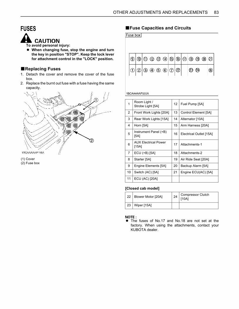
83OTHER ADJUSTMENTS AND REPLACEMENTS
FUSES
To avoid personal injury:A When changing fuse, stop the engine and turn
the key in position "STOP". Keep the lock leverfor attachment control in the "LOCK" position.
BReplacing Fuses1. Detach the cover and remove the cover of the fuse
box. 2. Replace the burnt out fuse with a fuse having the same
capacity.
BFuse Capacities and Circuits
[Closed cab model]
A The fuses of No.17 and No.18 are not set at thefactory. When using the attachments, contact yourKUBOTA dealer.
(1) Cover(2) Fuse box
1 Room Light /Strobe Light [5A] 12 Fuel Pump [5A]
2 Front Work Lights [20A] 13 Control Element [5A]
3 Rear Work Lights [15A] 14 Alternator [10A]
4 Horn [5A] 15 Arm Harness [20A]
5 Instrument Panel (+B) [5A] 16 Electrical Outlet [15A]
6 AUX Electrical Power [15A] 17 Attachments-1
7 ECU (+B) [5A] 18 Attachments-2
8 Starter [5A] 19 Air Ride Seat [20A]
9 Engine Elements [5A] 20 Backup Alarm [5A]
10 Switch (AC) [5A] 21 Engine ECU(AC) [5A]
11 ECU (AC) [20A]
22 Blower Motor [20A] 24 Compressor Clutch [10A]
23 Wiper [15A]
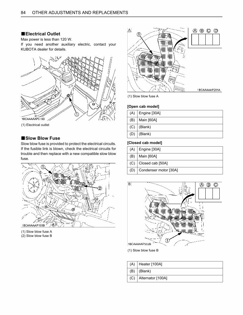
OTHER ADJUSTMENTS AND REPLACEMENTS84
BElectrical OutletMax power is less than 120 W.If you need another auxiliary electric, contact yourKUBOTA dealer for details.
BSlow Blow FuseSlow blow fuse is provided to protect the electrical circuits.If the fusible link is blown, check the electrical circuits fortrouble and then replace with a new compatible slow blowfuse.
[Open cab model]
[Closed cab model]
(1) Electrical outlet
(1) Slow blow fuse A(2) Slow blow fuse B
(1) Slow blow fuse A
(A) Engine [30A]
(B) Main [60A]
(C) (Blank)
(D) (Blank)
(A) Engine [30A]
(B) Main [60A]
(C) Closed cab [50A]
(D) Condenser motor [30A]
(1) Slow blow fuse B
(A) Heater [100A]
(B) (Blank)
(C) Alternator [100A]
85TROUBLESHOOTING
TROUBLESHOOTING
If the machine does not show the desired performance, or when trouble arises, refer to the table below and undertakeappropriate measures.Trouble Cause Countermeasure
Engine
Starting difficulties
Fuel is too viscous.* Check fuel tank and filter.* Remove impurities and water.* If necessary, replace filter.
Air or water in the fuel system
* Remove water from the fuel tank.* Check fuel pipe joint bolts and nuts for looseness.* Purging of the fuel system (for fuel filter and supply pump, see "PURGING OF THE FUEL SYSTEM" in . "OTHER ADJUSTMENTS AND REPLACEMENTS" section.)
Fuse is blown out. * Check the fuse and replace it with a same-capacity one as required.
Oil viscosity is too high the engine runs sluggishly in winter. * Use the engine block heater (option).
Battery is almost dead; insufficient compression. * Recharge battery.
Insufficient engine power
Low fuel level * Check fuel and add if necessary.Clogged air cleaner * Clean the air cleaner element.
Engine suddenly stops. Low fuel level * Check fuel and add if necessary.
* Purge the fuel system.
Abnormal exhaust gas color
Poor fuel * Use high quality fuel.Too much engine oil * Drain engine oil to prescribed oil level.
Water temperaturein red zone (Overheating)
Defective seal of the water pump * Replace.
Worn or torn V-belt * Adjust or replace.Thermostat is defect. * Replace.Coolant level too low * Fill to prescribed level.Radiator grill or fins are clogged. * Clean.Coolant is contaminated with rust from the cylinder head or crank case.
* Replace coolant fluid and add anti-rust.
Defective radiator cap (Evaporation) * Replace.
Corroded coolant pipes * Clean.Continuous operation under full load * Reduce load.
Cylinder head gasket is damaged (Coolant loss). * Replace.
Engine oil level too low * Fill to prescribed level.Maladjustment of fuel injection * Readjust ignition timing.Use of poor fuel * Use prescribed fuel.
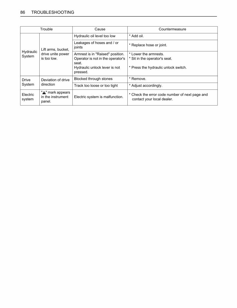
86 TROUBLESHOOTING
Hydraulic System
Lift arms, bucket, drive unite power is too low.
Hydraulic oil level too low * Add oil.
Leakages of hoses and / or joints * Replace hose or joint.
Armrest is in "Raised" position.Operator is not in the operator's seat.Hydraulic unlock lever is not pressed.
* Lower the armrests.* Sit in the operator's seat.
* Press the hydraulic unlock switch.
Drive System
Deviation of drive direction
Blocked through stones * Remove.
Track too loose or too tight * Adjust accordingly.
Electric system
" " mark appears in the instrument panel.
Electric system is malfunction. * Check the error code number of next page and contact your local dealer.
Trouble Cause Countermeasure
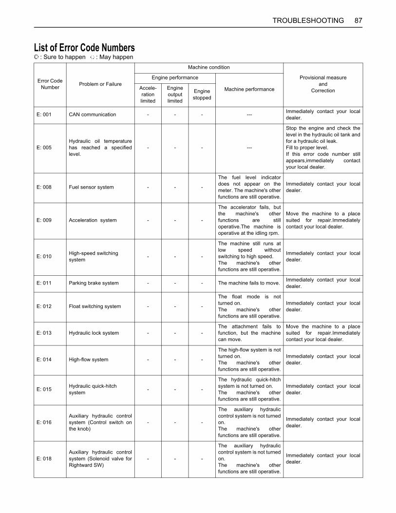
87TROUBLESHOOTING
List of Error Code Numbers : Sure to happen : May happen
Error Code Number Problem or Failure
Machine condition
Provisional measure and
Correction
Engine performance
Machine performanceAccele-ration limited
Engine output limited
Engine stopped
E: 001 CAN communication - - - --- Immediately contact your localdealer.
E: 005Hydraulic oil temperaturehas reached a specifiedlevel.
- - - ---
Stop the engine and check thelevel in the hydraulic oil tank andfor a hydraulic oil leak.Fill to proper level.If this error code number stillappears,immediately contactyour local dealer.
E: 008 Fuel sensor system - - -
The fuel level indicatordoes not appear on themeter. The machine's otherfunctions are still operative.
Immediately contact your localdealer.
E: 009 Acceleration system - - -
The accelerator fails, butthe machine's otherfunctions are stilloperative.The machine isoperative at the idling rpm.
Move the machine to a placesuited for repair.Immediatelycontact your local dealer.
E: 010 High-speed switching system - - -
The machine still runs atlow speed withoutswitching to high speed.The machine's otherfunctions are still operative.
Immediately contact your localdealer.
E: 011 Parking brake system - - - The machine fails to move. Immediately contact your localdealer.
E: 012 Float switching system - - -
The float mode is notturned on.The machine's otherfunctions are still operative.
Immediately contact your localdealer.
E: 013 Hydraulic lock system - - -The attachment fails tofunction, but the machinecan move.
Move the machine to a placesuited for repair.Immediatelycontact your local dealer.
E: 014 High-flow system - - -
The high-flow system is notturned on.The machine's otherfunctions are still operative.
Immediately contact your localdealer.
E: 015 Hydraulic quick-hitch system - - -
The hydraulic quick-hitchsystem is not turned on.The machine's otherfunctions are still operative.
Immediately contact your localdealer.
E: 016Auxiliary hydraulic controlsystem (Control switch onthe knob)
- - -
The auxiliary hydrauliccontrol system is not turnedon.The machine's otherfunctions are still operative.
Immediately contact your localdealer.
E: 018Auxiliary hydraulic controlsystem (Solenoid valve forRightward SW)
- - -
The auxiliary hydrauliccontrol system is not turnedon.The machine's otherfunctions are still operative.
Immediately contact your localdealer.
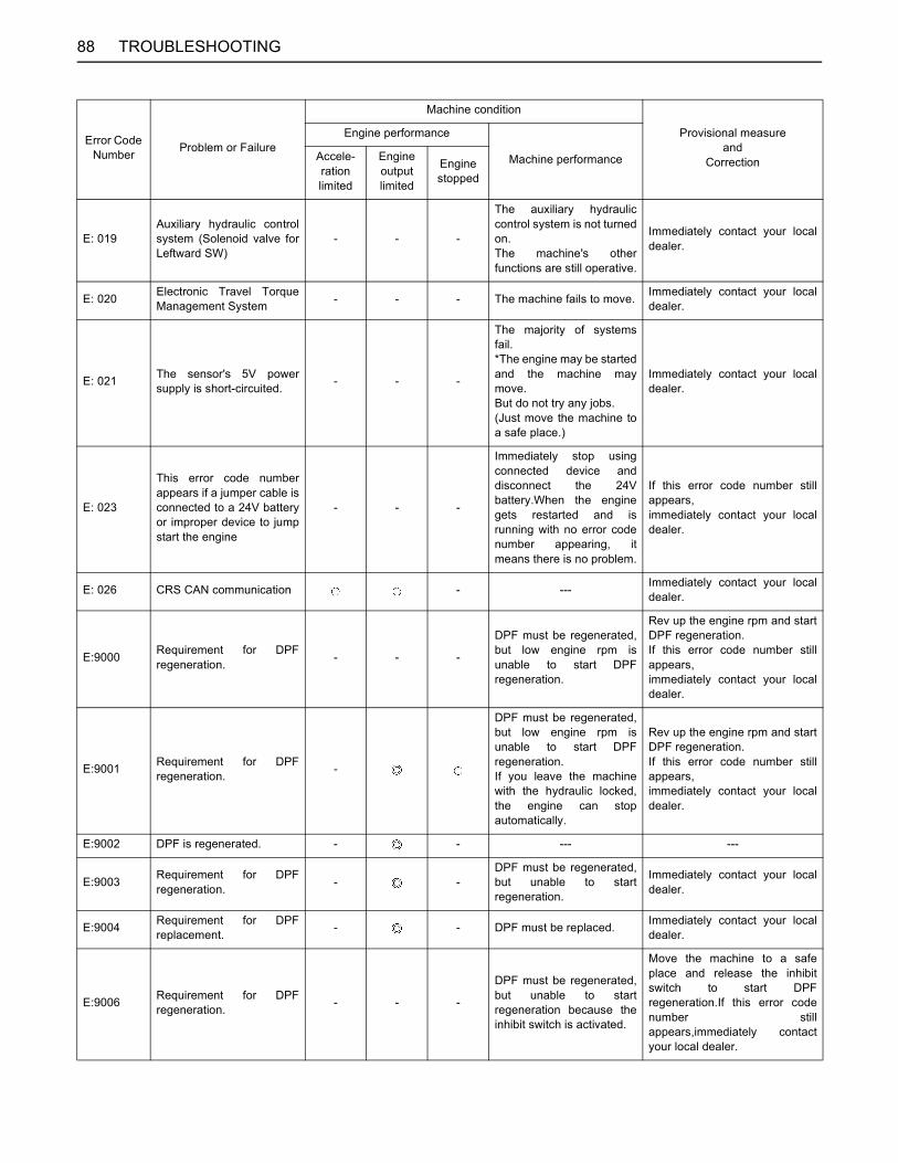
88 TROUBLESHOOTING
E: 019Auxiliary hydraulic controlsystem (Solenoid valve forLeftward SW)
- - -
The auxiliary hydrauliccontrol system is not turnedon.The machine's otherfunctions are still operative.
Immediately contact your localdealer.
E: 020 Electronic Travel TorqueManagement System - - - The machine fails to move. Immediately contact your local
dealer.
E: 021 The sensor's 5V powersupply is short-circuited. - - -
The majority of systemsfail.*The engine may be startedand the machine maymove.But do not try any jobs.(Just move the machine toa safe place.)
Immediately contact your localdealer.
E: 023
This error code numberappears if a jumper cable isconnected to a 24V batteryor improper device to jumpstart the engine
- - -
Immediately stop usingconnected device anddisconnect the 24Vbattery.When the enginegets restarted and isrunning with no error codenumber appearing, itmeans there is no problem.
If this error code number stillappears,immediately contact your localdealer.
E: 026 CRS CAN communication - --- Immediately contact your localdealer.
E:9000 Requirement for DPFregeneration. - - -
DPF must be regenerated,but low engine rpm isunable to start DPFregeneration.
Rev up the engine rpm and startDPF regeneration.If this error code number stillappears,immediately contact your localdealer.
E:9001 Requirement for DPFregeneration. -
DPF must be regenerated,but low engine rpm isunable to start DPFregeneration.If you leave the machinewith the hydraulic locked,the engine can stopautomatically.
Rev up the engine rpm and startDPF regeneration.If this error code number stillappears,immediately contact your localdealer.
E:9002 DPF is regenerated. - - --- ---
E:9003 Requirement for DPFregeneration. - -
DPF must be regenerated,but unable to startregeneration.
Immediately contact your localdealer.
E:9004 Requirement for DPFreplacement. - - DPF must be replaced. Immediately contact your local
dealer.
E:9006 Requirement for DPFregeneration. - - -
DPF must be regenerated,but unable to startregeneration because theinhibit switch is activated.
Move the machine to a safeplace and release the inhibitswitch to start DPFregeneration.If this error codenumber stillappears,immediately contactyour local dealer.
Error Code Number Problem or Failure
Machine condition
Provisional measure and
Correction
Engine performance
Machine performanceAccele-ration limited
Engine output limited
Engine stopped
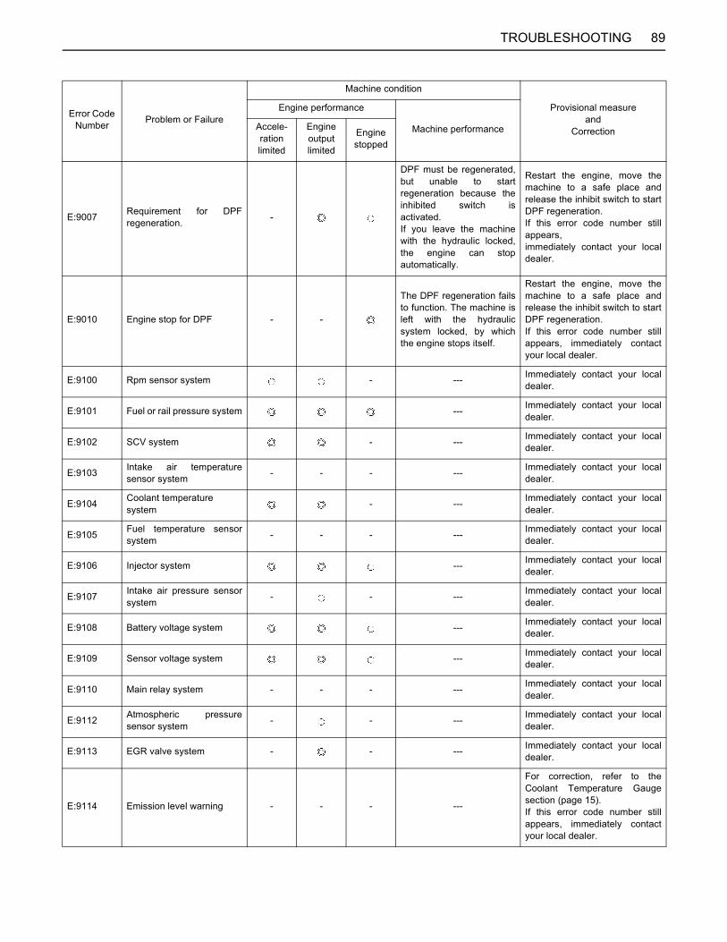
89TROUBLESHOOTING
E:9007 Requirement for DPFregeneration. -
DPF must be regenerated,but unable to startregeneration because theinhibited switch isactivated.If you leave the machinewith the hydraulic locked,the engine can stopautomatically.
Restart the engine, move themachine to a safe place andrelease the inhibit switch to startDPF regeneration.If this error code number stillappears,immediately contact your localdealer.
E:9010 Engine stop for DPF - -
The DPF regeneration failsto function. The machine isleft with the hydraulicsystem locked, by whichthe engine stops itself.
Restart the engine, move themachine to a safe place andrelease the inhibit switch to startDPF regeneration.If this error code number stillappears, immediately contactyour local dealer.
E:9100 Rpm sensor system - --- Immediately contact your localdealer.
E:9101 Fuel or rail pressure system --- Immediately contact your localdealer.
E:9102 SCV system - --- Immediately contact your localdealer.
E:9103 Intake air temperaturesensor system - - - --- Immediately contact your local
dealer.
E:9104 Coolant temperature system - --- Immediately contact your local
dealer.
E:9105 Fuel temperature sensorsystem - - - --- Immediately contact your local
dealer.
E:9106 Injector system --- Immediately contact your localdealer.
E:9107 Intake air pressure sensorsystem - - --- Immediately contact your local
dealer.
E:9108 Battery voltage system --- Immediately contact your localdealer.
E:9109 Sensor voltage system --- Immediately contact your localdealer.
E:9110 Main relay system - - - --- Immediately contact your localdealer.
E:9112 Atmospheric pressuresensor system - - --- Immediately contact your local
dealer.
E:9113 EGR valve system - - --- Immediately contact your localdealer.
E:9114 Emission level warning - - - ---
For correction, refer to theCoolant Temperature Gaugesection (page 15).If this error code number stillappears, immediately contactyour local dealer.
Error Code Number Problem or Failure
Machine condition
Provisional measure and
Correction
Engine performance
Machine performanceAccele-ration limited
Engine output limited
Engine stopped
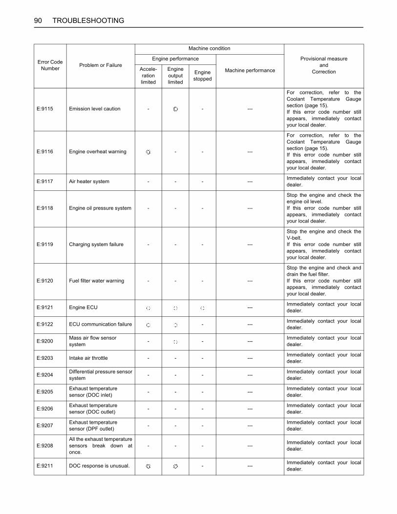
90 TROUBLESHOOTING
E:9115 Emission level caution - - ---
For correction, refer to theCoolant Temperature Gaugesection (page 15).If this error code number stillappears, immediately contactyour local dealer.
E:9116 Engine overheat warning - - ---
For correction, refer to theCoolant Temperature Gaugesection (page 15).If this error code number stillappears, immediately contactyour local dealer.
E:9117 Air heater system - - - --- Immediately contact your localdealer.
E:9118 Engine oil pressure system - - - ---
Stop the engine and check theengine oil level.If this error code number stillappears, immediately contactyour local dealer.
E:9119 Charging system failure - - - ---
Stop the engine and check theV-belt.If this error code number stillappears, immediately contactyour local dealer.
E:9120 Fuel filter water warning - - - ---
Stop the engine and check anddrain the fuel filter. If this error code number stillappears, immediately contactyour local dealer.
E:9121 Engine ECU --- Immediately contact your localdealer.
E:9122 ECU communication failure - --- Immediately contact your localdealer.
E:9200 Mass air flow sensor system - - --- Immediately contact your local
dealer.
E:9203 Intake air throttle - - - --- Immediately contact your localdealer.
E:9204 Differential pressure sensorsystem - - - --- Immediately contact your local
dealer.
E:9205 Exhaust temperature sensor (DOC inlet) - - - --- Immediately contact your local
dealer.
E:9206 Exhaust temperature sensor (DOC outlet) - - - --- Immediately contact your local
dealer.
E:9207 Exhaust temperature sensor (DPF outlet) - - - --- Immediately contact your local
dealer.
E:9208All the exhaust temperaturesensors break down atonce.
- - - --- Immediately contact your localdealer.
E:9211 DOC response is unusual. - --- Immediately contact your localdealer.
Error Code Number Problem or Failure
Machine condition
Provisional measure and
Correction
Engine performance
Machine performanceAccele-ration limited
Engine output limited
Engine stopped
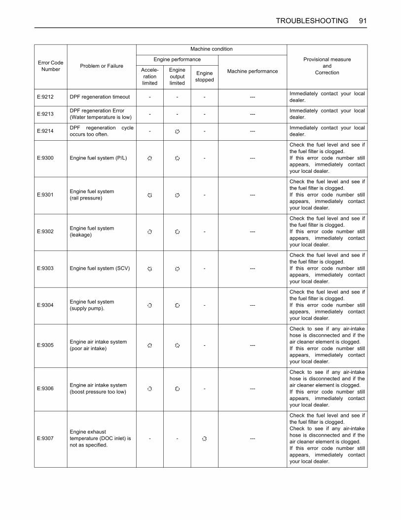
91TROUBLESHOOTING
E:9212 DPF regeneration timeout - - - --- Immediately contact your localdealer.
E:9213 DPF regeneration Error (Water temperature is low) - - - --- Immediately contact your local
dealer.
E:9214 DPF regeneration cycleoccurs too often. - - --- Immediately contact your local
dealer.
E:9300 Engine fuel system (P/L) - ---
Check the fuel level and see ifthe fuel filter is clogged.If this error code number stillappears, immediately contactyour local dealer.
E:9301 Engine fuel system (rail pressure) - ---
Check the fuel level and see ifthe fuel filter is clogged.If this error code number stillappears, immediately contactyour local dealer.
E:9302 Engine fuel system (leakage) - ---
Check the fuel level and see ifthe fuel filter is clogged.If this error code number stillappears, immediately contactyour local dealer.
E:9303 Engine fuel system (SCV) - ---
Check the fuel level and see ifthe fuel filter is clogged.If this error code number stillappears, immediately contactyour local dealer.
E:9304 Engine fuel system(supply pump). - ---
Check the fuel level and see ifthe fuel filter is clogged.If this error code number stillappears, immediately contactyour local dealer.
E:9305 Engine air intake system(poor air intake) - ---
Check to see if any air-intakehose is disconnected and if theair cleaner element is clogged.If this error code number stillappears, immediately contactyour local dealer.
E:9306 Engine air intake system (boost pressure too low) - ---
Check to see if any air-intakehose is disconnected and if theair cleaner element is clogged.If this error code number stillappears, immediately contactyour local dealer.
E:9307Engine exhaust temperature (DOC inlet) is not as specified.
- - ---
Check the fuel level and see ifthe fuel filter is clogged.Check to see if any air-intakehose is disconnected and if theair cleaner element is clogged.If this error code number stillappears, immediately contactyour local dealer.
Error Code Number Problem or Failure
Machine condition
Provisional measure and
Correction
Engine performance
Machine performanceAccele-ration limited
Engine output limited
Engine stopped
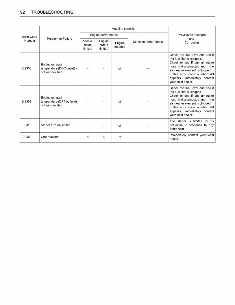
92 TROUBLESHOOTING
E:9308Engine exhaust temperature (DOC outlet) is not as specified.
- - ---
Check the fuel level and see ifthe fuel filter is clogged.Check to see if any air-intakehose is disconnected and if theair cleaner element is clogged.If this error code number stillappears, immediately contactyour local dealer.
E:9309Engine exhaust temperature (DPF outlet) is not as specified.
- - ---
Check the fuel level and see ifthe fuel filter is clogged.Check to see if any air-intakehose is disconnected and if theair cleaner element is clogged.If this error code number stillappears, immediately contactyour local dealer.
E:9310 Starter turn-on limited - - ---The starter is limited for itsactivation in response to anyother error
E:9400 Other failures --- Immediately contact your localdealer.
Error Code Number Problem or Failure
Machine condition
Provisional measure and
Correction
Engine performance
Machine performanceAccele-ration limited
Engine output limited
Engine stopped
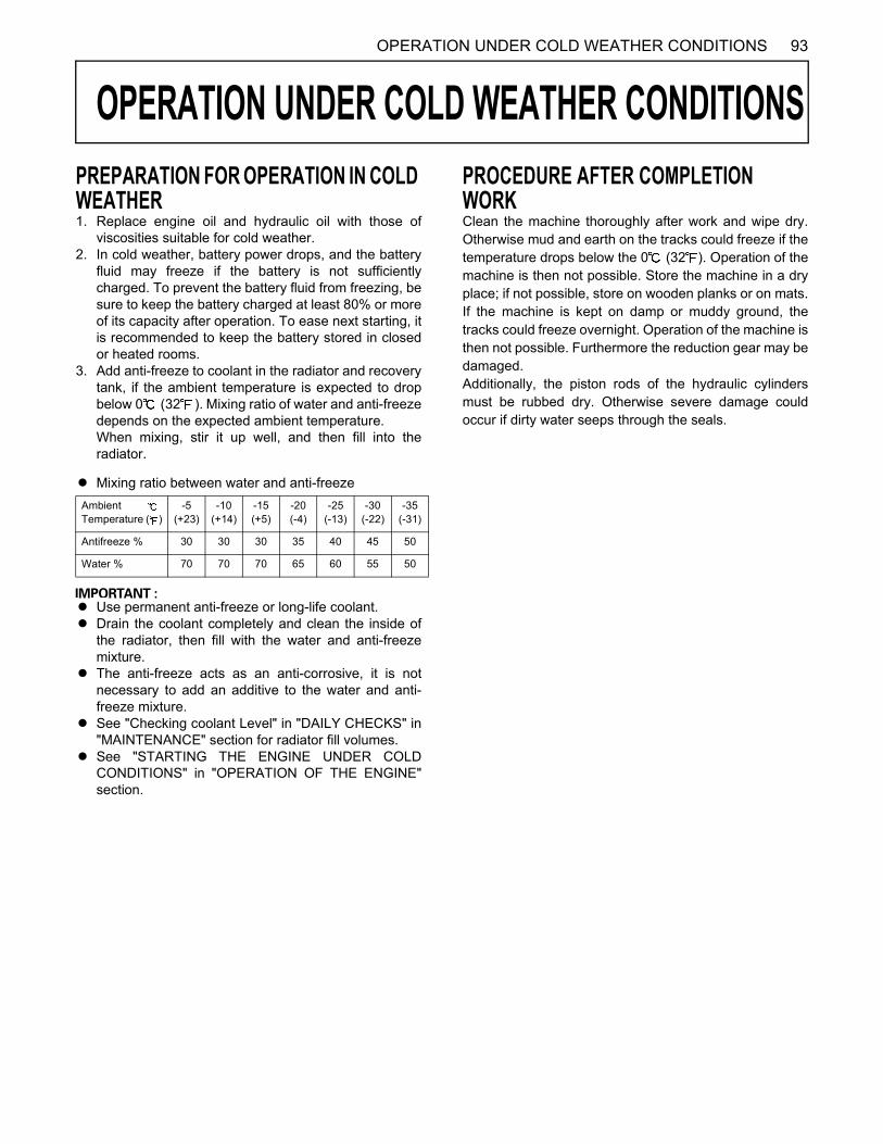
93OPERATION UNDER COLD WEATHER CONDITIONS
OPERATION UNDER COLD WEATHER CONDITIONS
PREPARATION FOR OPERATION IN COLD WEATHER1. Replace engine oil and hydraulic oil with those ofviscosities suitable for cold weather.2. In cold weather, battery power drops, and the battery
fluid may freeze if the battery is not sufficientlycharged. To prevent the battery fluid from freezing, besure to keep the battery charged at least 80% or moreof its capacity after operation. To ease next starting, itis recommended to keep the battery stored in closedor heated rooms.
3. Add anti-freeze to coolant in the radiator and recoverytank, if the ambient temperature is expected to dropbelow 0 (32 ). Mixing ratio of water and anti-freezedepends on the expected ambient temperature.When mixing, stir it up well, and then fill into theradiator.
A Mixing ratio between water and anti-freeze
A Use permanent anti-freeze or long-life coolant.A Drain the coolant completely and clean the inside of
the radiator, then fill with the water and anti-freezemixture.
A The anti-freeze acts as an anti-corrosive, it is notnecessary to add an additive to the water and anti-freeze mixture.
A See "Checking coolant Level" in "DAILY CHECKS" in"MAINTENANCE" section for radiator fill volumes.
A See "STARTING THE ENGINE UNDER COLDCONDITIONS" in "OPERATION OF THE ENGINE"section.
PROCEDURE AFTER COMPLETION WORKClean the machine thoroughly after work and wipe dry.Otherwise mud and earth on the tracks could freeze if thetemperature drops below the 0 (32 ). Operation of themachine is then not possible. Store the machine in a dryplace; if not possible, store on wooden planks or on mats.If the machine is kept on damp or muddy ground, thetracks could freeze overnight. Operation of the machine isthen not possible. Furthermore the reduction gear may bedamaged.Additionally, the piston rods of the hydraulic cylindersmust be rubbed dry. Otherwise severe damage couldoccur if dirty water seeps through the seals.
Ambient Temperature ( )
-5(+23)
-10(+14)
-15(+5)
-20(-4)
-25(-13)
-30(-22)
-35(-31)
Antifreeze % 30 30 30 35 40 45 50
Water % 70 70 70 65 60 55 50
94 LONG STORAGE
LONG STORAGE
To avoid personal injury: A Do not clean the machine with the engine running.A To avoid the danger of exhaust fume poisoning, do not operate the engine in a closed building or any areas
without proper ventilation.A When storing, remove the key from the starter switch to avoid unauthorized persons from operating the
machine and getting injured.A Bring the machine on a firm, flat, and level surface. Lower the lift arms on the ground.
B Should the Machine be Stored for a Longer Period of Time, Observe Following Procedures:1. The whole machine should be cleaned thoroughly and in all cases stored indoors. If the machine has to be kept
outdoors, lay out wooden planks on even ground, place the machine on the planks and cover completely.2. Do an oil change and grease the machine.3. Heavily grease the visible section of the cylinder rods.4. Remove the battery and store indoors.5. If it is expected that the temperature will sink below the 0 (32 ), add anti-freeze or drain coolant completely.
A Wash the machine after stopping the engine.If you wash the machine while running the engine, splashing water gets into the air cleaner through its intake andcause engine damage.Carefully, wash and do not splash water over the air cleaner while the engine is running.
B Observe Following Procedures when the Machine is to be Operated after Long Storage.1. Wipe off the grease from the hydraulic cylinder rods.2. Turn on the engine and operate the attachments and the drive mechanisms under no load in order to circulate the
hydraulic oil. (If the machine is stored for longer than one month, do steps 1 and 2 once every month.)
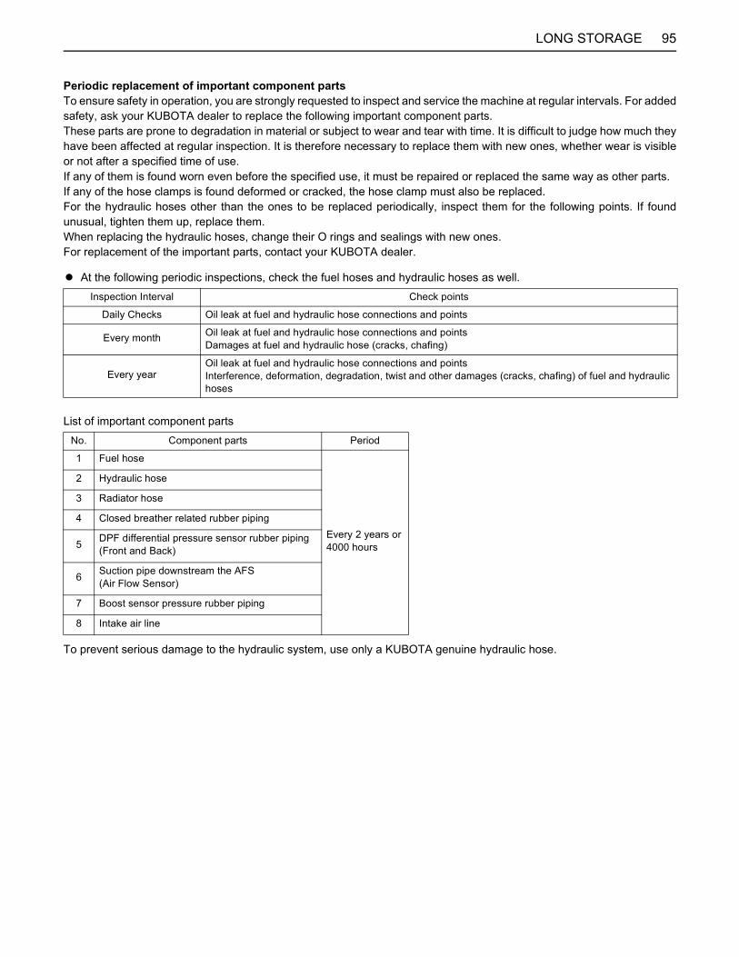
95LONG STORAGE
Periodic replacement of important component partsTo ensure safety in operation, you are strongly requested to inspect and service the machine at regular intervals. For addedsafety, ask your KUBOTA dealer to replace the following important component parts.These parts are prone to degradation in material or subject to wear and tear with time. It is difficult to judge how much theyhave been affected at regular inspection. It is therefore necessary to replace them with new ones, whether wear is visibleor not after a specified time of use.If any of them is found worn even before the specified use, it must be repaired or replaced the same way as other parts.If any of the hose clamps is found deformed or cracked, the hose clamp must also be replaced.For the hydraulic hoses other than the ones to be replaced periodically, inspect them for the following points. If foundunusual, tighten them up, replace them.When replacing the hydraulic hoses, change their O rings and sealings with new ones.For replacement of the important parts, contact your KUBOTA dealer.
A At the following periodic inspections, check the fuel hoses and hydraulic hoses as well.
List of important component parts
To prevent serious damage to the hydraulic system, use only a KUBOTA genuine hydraulic hose.
Inspection Interval Check points
Daily Checks Oil leak at fuel and hydraulic hose connections and points
Every month Oil leak at fuel and hydraulic hose connections and pointsDamages at fuel and hydraulic hose (cracks, chafing)
Every yearOil leak at fuel and hydraulic hose connections and pointsInterference, deformation, degradation, twist and other damages (cracks, chafing) of fuel and hydraulic hoses
No. Component parts Period
1 Fuel hose
Every 2 years or4000 hours
2 Hydraulic hose
3 Radiator hose
4 Closed breather related rubber piping
5 DPF differential pressure sensor rubber piping (Front and Back)
6 Suction pipe downstream the AFS (Air Flow Sensor)
7 Boost sensor pressure rubber piping
8 Intake air line
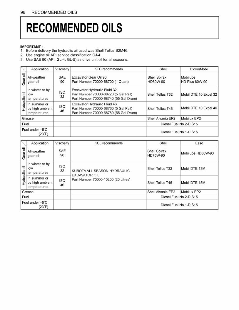
96 RECOMMENDED OILS
RECOMMENDED OILS
1. Before delivery the hydraulic oil used was Shell Tellus S2M46.2. Use engine oil API service classification CJ-4.3. Use SAE 90 (API, GL-4, GL-5) as drive unit oil for all seasons.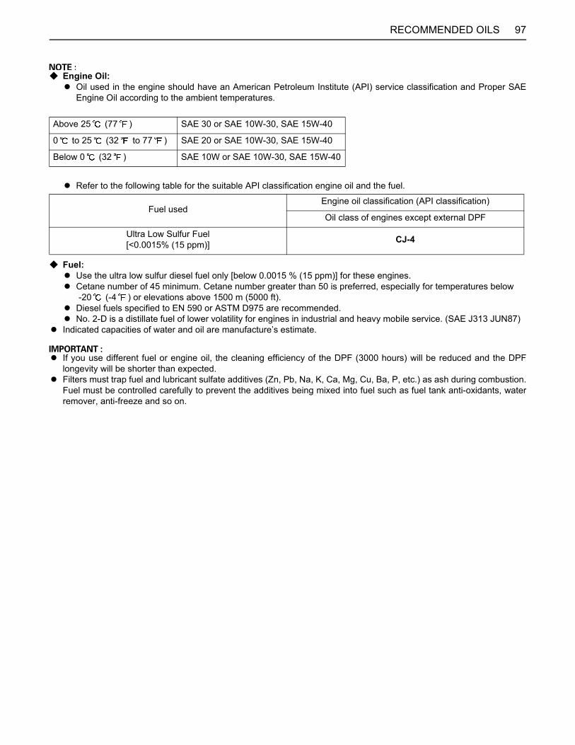
97RECOMMENDED OILS
C Engine Oil:A Oil used in the engine should have an American Petroleum Institute (API) service classification and Proper SAE
Engine Oil according to the ambient temperatures.
A Refer to the following table for the suitable API classification engine oil and the fuel.
C Fuel:A Use the ultra low sulfur diesel fuel only [below 0.0015 % (15 ppm)] for these engines.A Cetane number of 45 minimum. Cetane number greater than 50 is preferred, especially for temperatures below
-20 (-4 ) or elevations above 1500 m (5000 ft).A Diesel fuels specified to EN 590 or ASTM D975 are recommended.A No. 2-D is a distillate fuel of lower volatility for engines in industrial and heavy mobile service. (SAE J313 JUN87)
A Indicated capacities of water and oil are manufacture’s estimate.
A If you use different fuel or engine oil, the cleaning efficiency of the DPF (3000 hours) will be reduced and the DPFlongevity will be shorter than expected.
A Filters must trap fuel and lubricant sulfate additives (Zn, Pb, Na, K, Ca, Mg, Cu, Ba, P, etc.) as ash during combustion.Fuel must be controlled carefully to prevent the additives being mixed into fuel such as fuel tank anti-oxidants, waterremover, anti-freeze and so on.
Above 25 (77 ) SAE 30 or SAE 10W-30, SAE 15W-40
0 to 25 (32 to 77 ) SAE 20 or SAE 10W-30, SAE 15W-40
Below 0 (32 ) SAE 10W or SAE 10W-30, SAE 15W-40
Fuel usedEngine oil classification (API classification)
Oil class of engines except external DPF
Ultra Low Sulfur Fuel[<0.0015% (15 ppm)] CJ-4
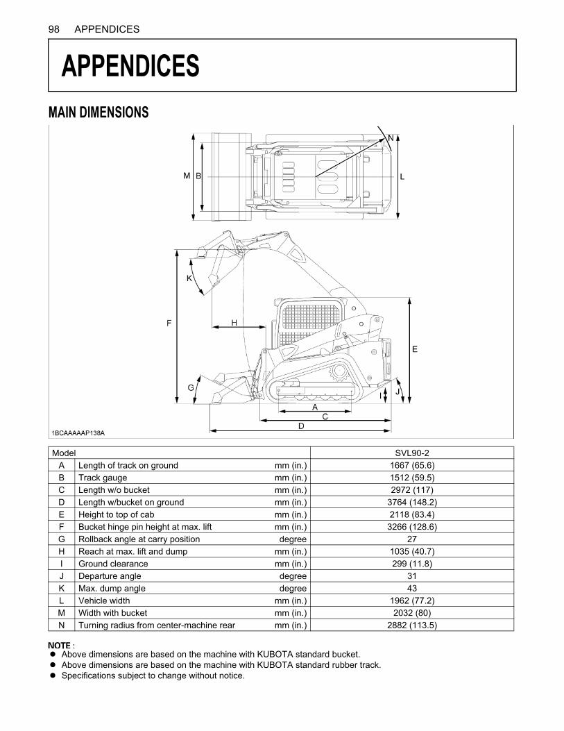
98 APPENDICES
APPENDICES
MAIN DIMENSIONSA Above dimensions are based on the machine with KUBOTA standard bucket.A Above dimensions are based on the machine with KUBOTA standard rubber track.A Specifications subject to change without notice.
Model SVL90-2A Length of track on ground mm (in.) 1667 (65.6)B Track gauge mm (in.) 1512 (59.5)C Length w/o bucket mm (in.) 2972 (117)D Length w/bucket on ground mm (in.) 3764 (148.2)E Height to top of cab mm (in.) 2118 (83.4)F Bucket hinge pin height at max. lift mm (in.) 3266 (128.6)G Rollback angle at carry position degree 27H Reach at max. lift and dump mm (in.) 1035 (40.7)I Ground clearance mm (in.) 299 (11.8)J Departure angle degree 31K Max. dump angle degree 43L Vehicle width mm (in.) 1962 (77.2)M Width with bucket mm (in.) 2032 (80)N Turning radius from center-machine rear mm (in.) 2882 (113.5)