Embed Size (px)
Citation preview

TP221-03 December 3, 2003
U.S. DEPARTMENT OF TRANSPORTATION
NATIONAL HIGHWAY TRAFFIC SAFETY ADMINISTRATION
LABORATORY TEST PROCEDURE
FOR
FMVSS 221
School Bus Body Joint Strength
Enforcement Office of Vehicle Safety Compliance
Room 6111 NVS-220 400 Seventh Street, SW Washington, DC 20590

OVSC LABORATORY TEST PROCEDURE NO. 221 TABLE OF CONTENTS
PAGE
1. REVISION CONTROL LOG .......................................................................................... 1
2. PURPOSE AND APPLICATION ................................................................................... 2
3. GENERAL REQUIREMENTS ....................................................................................... 3
4. SECURITY .................................................................................................................... 3
5. GOOD HOUSEKEEPING ............................................................................................. 4
6. TEST SCHEDULING AND MONITORING.................................................................... 4
7. TEST DATA DISPOSITION .......................................................................................... 5
8. GOVERNMENT FURNISHED PROPERTY (GFP) ....................................................... 5
9. CALIBRATION OF TEST INSTRUMENTS ................................................................... 6
10. PHOTOGRAPHIC DOCUMENTATION ........................................................................ 7
11. DEFINITIONS ............................................................................................................... 8
12. PRETEST REQUIREMENTS........................................................................................ 16
13. COMPLIANCE TEST EXECUTION .............................................................................. 29
14. POSTTEST REQUIREMENTS ..................................................................................... 33
15. REPORTS ..................................................................................................................... 35
15.1. MONTHLY STATUS REPORTS ....................................................................... 35
15.2. FINAL TEST REPORTS ................................................................................... 35
15.2.1. COPIES ................................................................................................. 35
15.2.2. REQUIREMENTS.................................................................................. 35
15.2.3. FIRST THREE PAGES.......................................................................... 37
15.2.4. TABLE OF CONTENTS......................................................................... 42
16. DATA SHEETS ............................................................................................................. 43
17. FORMS ......................................................................................................................... 52
1
REVISION CONTROL LOG FOR OVSC LABORATORY
TEST PROCEDURES
TP-221 School bus body joint strength
TEST PROCEDURE FMVSS 221
DESCRIPTIONREV. No. DATE AMENDMENT
EFFECTIVE DATE
00 2/22/77 41FR36027 08/26/76 Original release signed by O.D.
01 8/3/79 Rearrange contents and update
02 Update, make corrections and add clarifications
03 12/03/03 66FR64358 01/01/03 Applicable to all school buses. Fastener spacing requirements included.
04
05
06
07
08
09
10

2 1. PURPOSE AND APPLICATION
The Office of Vehicle Safety Compliance (OVSC) provides contractor laboratories with Laboratory Test Procedures as guidelines for obtaining compliance test data. The data are used to determine if a specific vehicle or item of motor vehicle equipment meets the minimum performance requirements of the subject Federal Motor Vehicle Safety Standard (FMVSS). The purpose of the OVSC Laboratory Test Procedures is to present a uniform testing and data recording format, and provide suggestions for the use of specific equipment and procedures. If any contractor views any part of an OVSC Laboratory Test Procedure to be in conflict with a Federal Motor Vehicle Safety Standard (FMVSS) or observes deficiencies in a Laboratory Test Procedure, the contractor is required to advise the Contracting Officer's Technical Representative (COTR) and resolve the discrepancy prior to the start of compliance testing.
Every contractor is required to submit a detailed test procedure to the COTR before initiating the compliance test program. The procedure must include a step by step description of the methodology to be used. The contractor’s test procedure shall contain a complete listing of test equipment with make and model number and a detailed check-off sheet. The list of test equipment shall include instrument accuracy and calibration dates. All equipment shall be calibrated in accordance with the manufacturer’s instructions. There shall be no contradictions between the Laboratory Test Procedure and the contractor’s inhouse test procedure. Written approval of the in-house test procedures shall be obtained from the COTR before initiating the compliance test program. The OVSC Laboratory Test Procedures are not intended to limit or restrain a contractor from developing or utilizing any testing techniques or equipment which will assist in procuring the required compliance test data. These Laboratory Test Procedures do not constitute an endorsement or recommendation for use of any product or method. However, the application of any such testing technique or equipment is subject to prior approval of the COTR.
NOTE: The OVSC Laboratory Test Procedures, prepared for the limited purpose of use by independent laboratories under contract to conduct compliance tests for the OVSC, are not rules, regulations or NHTSA interpretations regarding the meaning of a FMVSS. The Laboratory Test Procedures are not intended to limit the requirements of the applicable FMVSS(s). In some cases, the OVSC Laboratory Test Procedures do not include all of the various FMVSS minimum performance requirements. Recognizing applicable test tolerances, the Laboratory Test Procedures may specify test conditions that are less severe than the minimum requirements of the standard. In addition, the Laboratory Test Procedures may be modified by the OVSC at any time without notice, and the COTR may direct or authorize contractors to deviate from these procedures, as long as the tests are performed in a manner consistent with the standard itself and within the scope of the contract. Laboratory Test Procedures may not be relied upon to create any right or benefit in any person. Therefore, compliance of a vehicle or item of motor vehicle equipment is not necessarily guaranteed if the

3 1. PURPOSE AND APPLICATION....Continued
manufacturer limits its certification tests to those described in the OVSC Laboratory Test Procedures.
2. GENERAL REQUIREMENTS
FMVSS No. 221, School Bus Body Joint Strength, establishes strength requirements for the bus body joints that enclose the passenger compartment. The purpose of the standard is to reduce injuries resulting from the structural collapse of school bus bodies during crashes and to strengthen joints reducing the exposure of cutting edges that could cause serious injuries or allow passenger ejection through openings created by panel separations. The standard applies to school buses, including the multi-function school activity bus.
Each school bus body panel joint shall be capable of holding the body panel to the member to which it is joined when subjected to a force equal to 60 percent of the tensile strength of the weakest joined body panel determined as follows:
For purposes of determining the minimum allowable joint strength, determine the tensile strengths of the joined body components as follows –
A. If the mechanical properties of a material are specified by the American Society for Testing and Materials (ASTM), the relative tensile strength for such a material is the minimum tensile strength specified for that material in the 1989 edition of the Annual Book of ASTM Standards.
B. If the mechanical properties of a material are NOT specified by the ASTM, determine its tensile strength by cutting a specimen from the school bus body outside the area of the joint and test it as follows:
STRENGTH TEST
(1) Grip the joint specimen on opposite sides of the joint in a tension testing machine calibrated in accordance with ASTM Method E4-89, “Standard Practices for Load Verification of Testing Machines.”
(2) Adjust the testing machine grips so that the joint, under load, will be in stress at 90º ± 3º from the joint centerline.
(3) Apply a tensile force to the specimen by separating the heads of the testing machine at any uniform rate NOT less than 3 mm (0.125 inch) and not more than 10 mm (0.375 inch) per minute until the specimen separates.
(4) Body panels attached to each other shall have no unattached segment at the joint longer than 203 mm.

4 3. SECURITY
The contractor shall provide appropriate security measures to protect the OVSC test vehicles from unauthorized personnel during the entire compliance testing program. The contractor is financially responsible for any acts of theft and/or vandalism that occur during the storage of test vehicles. Any security problem shall be reported by telephone to the Industrial Property Manager (IPM), Office of Contracts and Procurement, within two working days after the incident. A letter containing specific details of the security problem will be sent to the IPM (with copy to the COTR) within 48 hours.
The contractor shall protect and segregate the data that evolves from compliance testing before and after each vehicle test. No information concerning the vehicle safety compliance testing program shall be released to anyone except the COTR, unless specifically authorized by the COTR or the COTR's Branch or Division Chief. The tested vehicles shall be protected from the elements and retained by the contractor for a minimum of 60 days so that NHTSA personnel can be given an inspection opportunity.
NOTE: No individuals, other than contractor personnel directly involved in the compliance testing program, shall be allowed to witness any vehicle compliance test unless specifically authorized by the COTR. It is the contractor's responsibility to secure the test site area during a test and to shield the test area from public view by the use of canvas or other blocking devices.
RULES FOR CONTRACTORS
A. No vehicle manufacturer's representative(s) or anyone other than the contractor's personnel working on the NHTSA contract program along with NHTSA personnel shall be allowed to inspect NHTSA vehicles or witness vehicle preparation without prior permission. Such permission shall never be assumed.
B. All communications with vehicle manufacturers shall be referred to the NHTSA. The contractor shall not release test data without the permission of the NHTSA.
4. GOOD HOUSEKEEPING
The contractor shall maintain the entire vehicle compliance testing area, test fixtures and instrumentation in a neat, clean and painted condition with test instruments arranged in an orderly manner consistent with good test laboratory housekeeping practices.

5 5. TEST SCHEDULING AND MONITORING
The contractor shall submit a test schedule to the COTR prior to testing. Tests shall be completed as required in the contract. Scheduling shall be adjusted to permit sample motor vehicles to be tested to other FMVSS as may be required by the OVSC. All testing shall be coordinated to allow monitoring by the COTR.
6. TEST DATA DISPOSITION
The contractor shall make all vehicle preliminary compliance test data available to the COTR on location within four hours after the test. Final test data, including digital printouts and computer generated plots, shall be furnished to the COTR within five working days. Additionally, the contractor shall analyze the preliminary test results as directed by the COTR.
All backup data sheets, recordings, plots, technicians notes, etc., shall be either sent to the COTR or destroyed at the conclusion of each delivery order, purchase order, etc.
7. GOVERNMENT FURNISHED PROPERTY (GFP)
ACCEPTANCE OF TEST VEHICLES
The contractor has the responsibility of accepting test vehicles from either new school bus dealers/distributors or bus transporters. In both instances, the contractor acts in the OVSC's behalf when signing an acceptance of test school buses. If a vehicle is delivered by a dealer/distributor, the contractor must check to verify the following:
A. Tires and wheel rims are new.
B. There are no dents or other interior or exterior flaws in the bus body.
C. The school bus has been properly prepared and is in running condition.
D. The glove box contains an owner's manual, warranty document, consumer information, and extra set of keys.
E. Proper fuel filler cap is supplied on the school bus.
F. All options listed on the “window sticker” are present on the test vehicle.
If the school bus test vehicle is delivered by a government contracted transporter, the contractor should check for damage which may have occurred during transit.

6 7. GOVERNMENT FURNISHED PROPERTY (GFP)…Continued
A "Vehicle Condition" form will be supplied to the contractor by the COTR when the school bus test vehicle is transferred from the bus manufacturer or distributor or between test contracts. The upper half of the form describes the school bus indetail, and the lower half provides space for a detailed description of the posttest condition. School Bus Test Vehicle Condition forms must be returned to the COTR with the copies of the Final Test Report or the reports will NOT be accepted.
NOTIFICATION OF COTR
The COTR must be notified within 24 hours after a school bus test vehicle has been delivered.
8. CALIBRATION OF TEST INSTRUMENTS
Before the contractor initiates the safety compliance test program, a test instrumentation calibration system will be implemented and maintained in accordance with established calibration practices. The calibration system shall be set up and maintained as follows:
A. Standards for calibrating the measuring and test equipment will be stored and used under appropriate environmental conditions to assure their accuracy and stability.
B. All measuring instruments and standards shall be calibrated by the contractor, or a commercial facility, against a higher order standard at periodic intervals NOT EXCEEDING 6 MONTHS FOR INSTRUMENTS AND 12 MONTHS FOR CALIBRATION STANDARDS. Records, showing the calibration traceability to the National Institute of Standards and Technology (NIST), shall be maintained for all measuring and test equipment.
C. All measuring and test equipment and measuring standards will be labeled with the following information:
(1) Date of calibration
(2) Date of next scheduled calibration
(3) Name of the technician who calibrated the equipment
D. A written calibration procedure shall be provided by the contractor including, as a minimum, the following information for all measurement and test equipment:
7 8. CALIBRATION OF TEST INSTRUMENTS....Continued
(1) Type of equipment, manufacturer, model number, etc.
(2) Measurement range
(3) Accuracy
(4) Calibration interval
(5) Type of standard used to calibrate the equipment (calibration traceability of the standard must be evident)
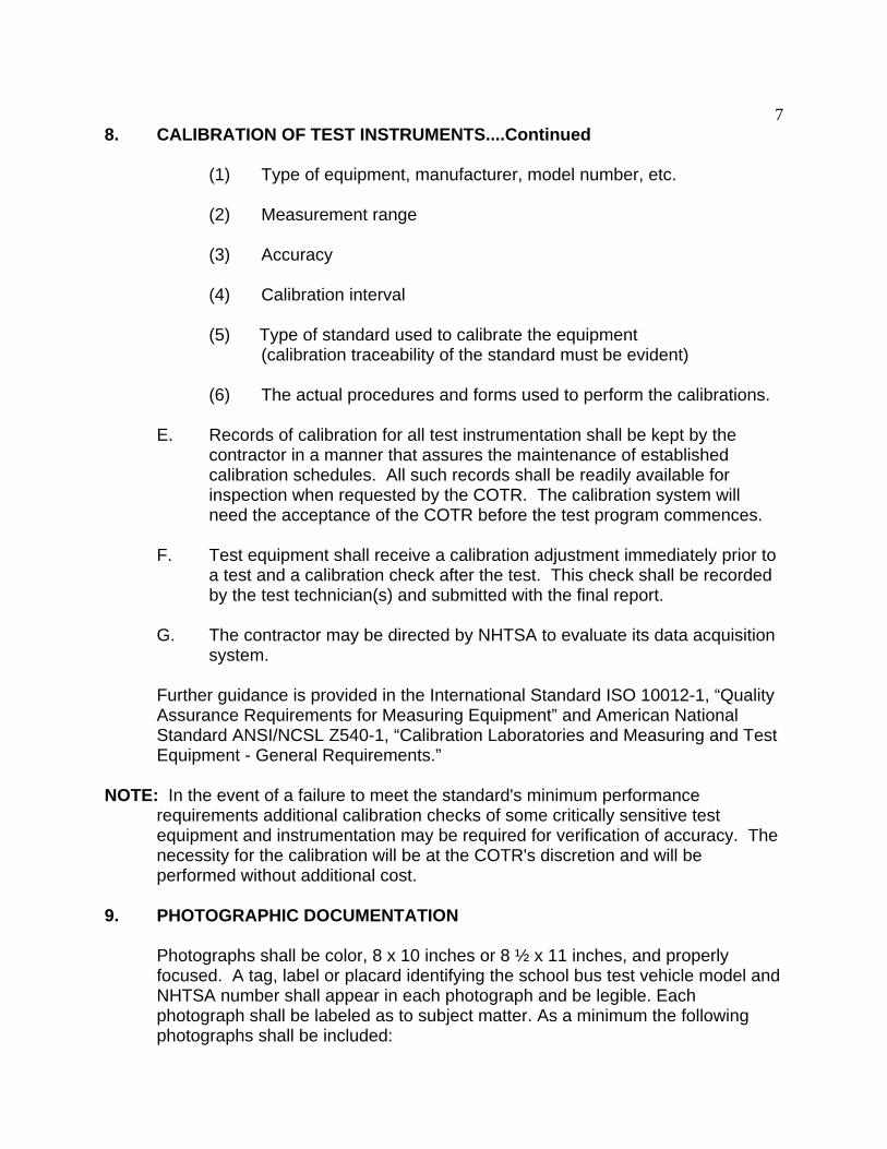
(6) The actual procedures and forms used to perform the calibrations.
E. Records of calibration for all test instrumentation shall be kept by the contractor in a manner that assures the maintenance of established calibration schedules. All such records shall be readily available for inspection when requested by the COTR. The calibration system will need the acceptance of the COTR before the test program commences.
F. Test equipment shall receive a calibration adjustment immediately prior to a test and a calibration check after the test. This check shall be recorded by the test technician(s) and submitted with the final report.
G. The contractor may be directed by NHTSA to evaluate its data acquisition system.
Further guidance is provided in the International Standard ISO 10012-1, “Quality Assurance Requirements for Measuring Equipment” and American National Standard ANSI/NCSL Z540-1, “Calibration Laboratories and Measuring and Test Equipment - General Requirements.”
NOTE: In the event of a failure to meet the standard's minimum performance requirements additional calibration checks of some critically sensitive test equipment and instrumentation may be required for verification of accuracy. The necessity for the calibration will be at the COTR's discretion and will be performed without additional cost.
9. PHOTOGRAPHIC DOCUMENTATION
Photographs shall be color, 8 x 10 inches or 8 ½ x 11 inches, and properly focused. A tag, label or placard identifying the school bus test vehicle model and NHTSA number shall appear in each photograph and be legible. Each photograph shall be labeled as to subject matter. As a minimum the following photographs shall be included:
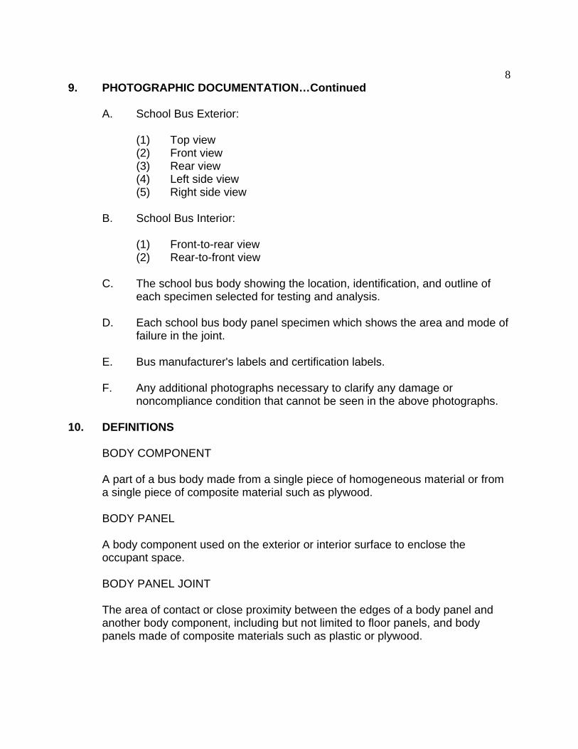
8 9. PHOTOGRAPHIC DOCUMENTATION…Continued
A. School Bus Exterior:
(1) Top view (2) Front view (3) Rear view (4) Left side view (5) Right side view
B. School Bus Interior:
(1) Front-to-rear view (2) Rear-to-front view
C. The school bus body showing the location, identification, and outline of each specimen selected for testing and analysis.
D. Each school bus body panel specimen which shows the area and mode of failure in the joint.
E. Bus manufacturer's labels and certification labels.
F. Any additional photographs necessary to clarify any damage or noncompliance condition that cannot be seen in the above photographs.
10. DEFINITIONS
BODY COMPONENT
A part of a bus body made from a single piece of homogeneous material or from a single piece of composite material such as plywood.
BODY PANEL
A body component used on the exterior or interior surface to enclose the occupant space.
BODY PANEL JOINT
The area of contact or close proximity between the edges of a body panel and another body component, including but not limited to floor panels, and body panels made of composite materials such as plastic or plywood.

9 10. DEFINITIONS….Continued
B O DY S E CT IO N A ND JO IN T SU P PO R T S T E M P E R A T U RE
14 0o (
A NG LE
) ( )
A
(6)
A
S E NS IT IVE S T IC K E R S 4 PL A CE S
A LU M IN U M S U P P O R T S 1" x 1 " x 1 /8 L
F O R A D H ES I V E J O IN T S
18 "
54 "
C R IM P P A N E L
S HIM SS HE E T M E T A L S CR EW S
BODY SECTION
(12)
V IEW A -A
Figure 1
A piece of the body that contains the joint specimen together with a sufficient portion of the surrounding bus body whose dimensions approximate those shown in Figure 1.
BUS
Means a motor vehicle with motive power, except a trailer, designed for carrying more than ten (10) persons.
BUS BODY
The portion of the bus that encloses the bus occupant space, including the floor and firewall (the body panel separating the engine compartment form the occupant space), but excluding the bumpers and chassis frame and any structure forward of the forward of the passenger compartment.
BUS OCCUPANT SPACE
The bus occupant space is defined as that portion of the bus interior that extends from the left and right side walls, from the floor to the ceiling, from the rear wall of the bus up to the forwardmost point of the windshield mounting.
10 10. DEFINITIONS....Continued
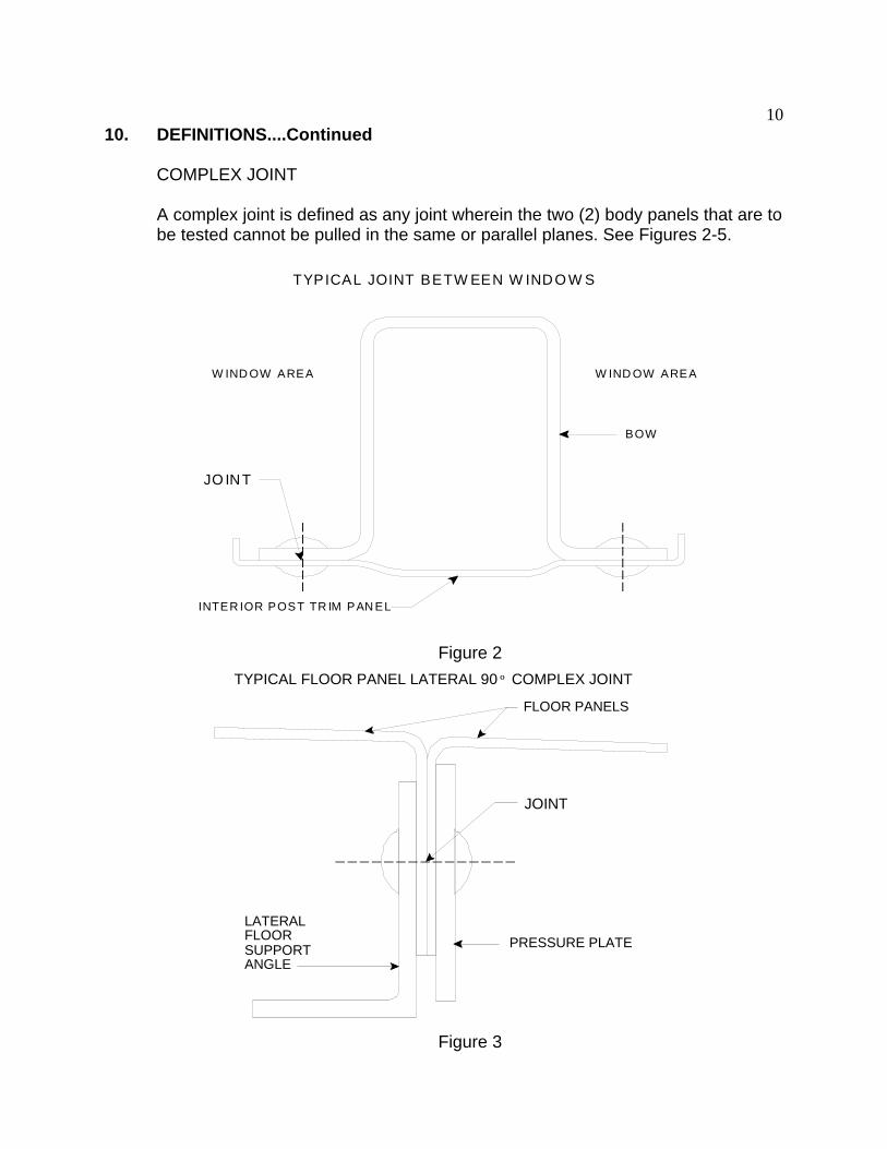
COMPLEX JOINT
A complex joint is defined as any joint wherein the two (2) body panels that are to be tested cannot be pulled in the same or parallel planes. See Figures 2-5.
T YPICA L JOINT BE T W EE N W IND O W S
JO IN T
W IND O W AREA
BO W
INT E R IO R PO ST T R IM PAN E L
W IND OW A RE A
Figure 2 TYPICAL FLOOR PANEL LATERAL 90 º COMPLEX JOINT
A
FLOOR PANELS
LATERAL FLOOR SUPPORT
NGLE PRESSURE PLATE
JOINT
Figure 3

11 10. DEFINITIONS....Continued
TYPICAL WINDOW SILL JOINT
SPOTWELD
JOINT
BOW
WINDOW SILL
TRIM MOLDING
INTERIOR PANEL EXTERIOR PANEL
Figure 4
TYPICAL COMPLEX JOINT OF SIDE WALL AND FLOOR
EXTERIOR PANEL SEAT W ALL ATTACH FLANGE
RUB RAIL GUSSET OR LOW ERINTERIOR PANEL
FLOOR PANEL
JOINT
BOW
JOINT
INTERIOR PANEL
GUSSET
JOINT
Figure 5
12 10. DEFINITIONS....Continued
FLOOR LINE
The lowest interior body panel that encloses the passenger compartment. Body components that are located entirely below the level of the floor are not normally subject to the standard. However, body components that do enclose bus occupant space because a portion lies above the floor line, are subject to the requirements. If plywood is attached to a floor panel on the surface inside the passenger compartment, and is only added for insulation purposes, it is not considered to have a function in enclosing the occupant space and is therefore not considered a body panel for purposes of the requirement.
FORCE
Is expressed in pounds and when used in this procedure means the material tensile strength of the weakest joined body panel in the specimen multiplied by that material area.
GAUGE
Gauge numbers are used to identify a material’s general thickness and are often used to specify a material when the thickness tolerance is not critical.
INTERIOR TRIM
Trim or decorative moldings that enclose occupant space are considered to be body panels, and where the edge comes in contact with another body component, create a joint subject to the requirements of FMVSS 221.
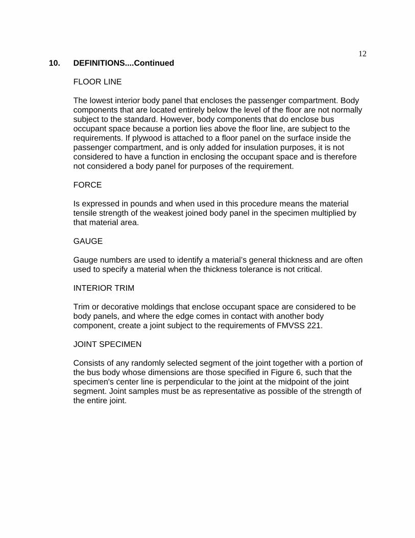
JOINT SPECIMEN
Consists of any randomly selected segment of the joint together with a portion of the bus body whose dimensions are those specified in Figure 6, such that the specimen's center line is perpendicular to the joint at the midpoint of the joint segment. Joint samples must be as representative as possible of the strength of the entire joint.
13 10. DEFINITIONS....Continued
DIMENSION REQUIREMENTS OF BODY PANEL WHOSE JOINT SEGMENT IS 8 INCHES
JOI
3"
4"
12"
4"
24" 3"
NT
SPECIMEN
24"
8" R.
NOTE: TOLERANCE ON ALL DIMENSIONS IS ± 1/16”
Figure 6
JOINT STRENGTH
The maximum load recorded when a joint specimen is tensile tested to separation. This force must be at least 60 percent of the material strength of the weakest component of the joint specimen.
MAINTENANCE ACCESS PANEL
A body panel which must be moved or removed to provide access to one or more serviceable component(s).
MATERIAL SPECIMEN
A piece of material that is cut from the school bus body outside the area of the joint specimen. Its size will conform to the dimensions referenced in the 1989 Annual Book of ASTM Standards, Method E8-89. Figure 7 provides an example of the shape of the test specimen.

14 10. DEFINITIONS....Continued
DIMENSIONS OF TENSILE TEST SPECIMEN DETERMINATION OF MATERIAL PROPERTIES AS TAKEN FROM 1989 ANNUAL BOOK OF ASTM STANDARDS PART 31, METHOD E-8
L
G
R
T
C
B A
W B
Figure 7
MATERIAL TENSILE STRENGTH
The maximum stress which a material is capable of sustaining when subjected to a tensile test. It is expressed in force per unit of area (such as pounds per square inch or Newtons per square meter) and can be calculated from the maximum load (pounds or Newtons) observed during a tension test that was carried to rupture, divided by the original cross sectional area (square inches or square meters) of the material specimen. The material tensile strength will be obtained from the 1989 Annual Book of the ASTM Standards when the mechanical properties and their minimum specified thickness are known. When the mechanical properties of a material are not known, then two material specimens will be tensile tested and the average result will be used.
MINIMUM THICKNESS
During manufacture, the thickness of materials is permitted to vary from the specified or nominal thickness by a small amount. If the thickness tolerance of a material is specified by the ASTM, use the minimum thickness specified for that material in the 1989 edition of the Annual Book of ASTM Standards. If the thickness tolerance of a material is not specified by the ASTM, use the thickness permitted by the school bus manufacturer's material specifications.
MULTIFUNCTION SCHOOL ACTIVITY BUS
A school bus whose purposes do not include transporting students to and from home or school bus stops.
15 10. DEFINITIONS....Continued
T Y P I C A L L A P J O I N T - - I N T E R I O R P A N E L W I T H A D H E S I V E B O N D I N G
-
B O W
E X T E R I O R P A N E L
J O I N T
I N T E R I O R P A N E L S
A D H E S IV E J O I N T
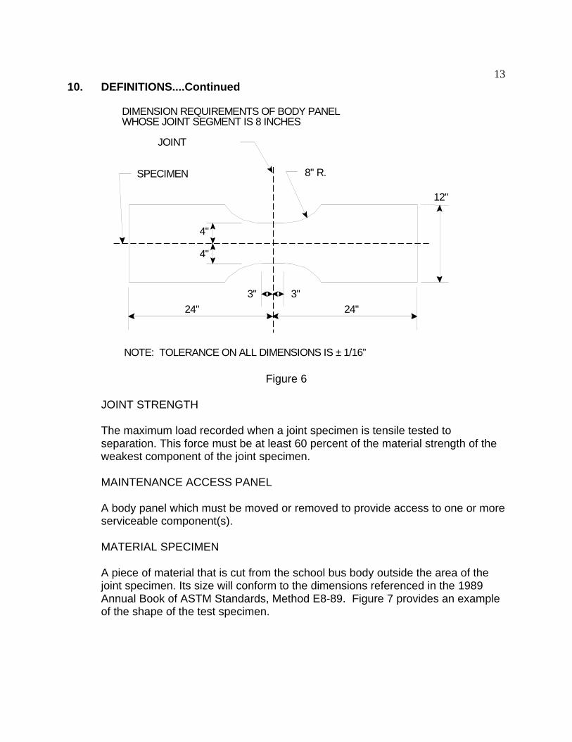
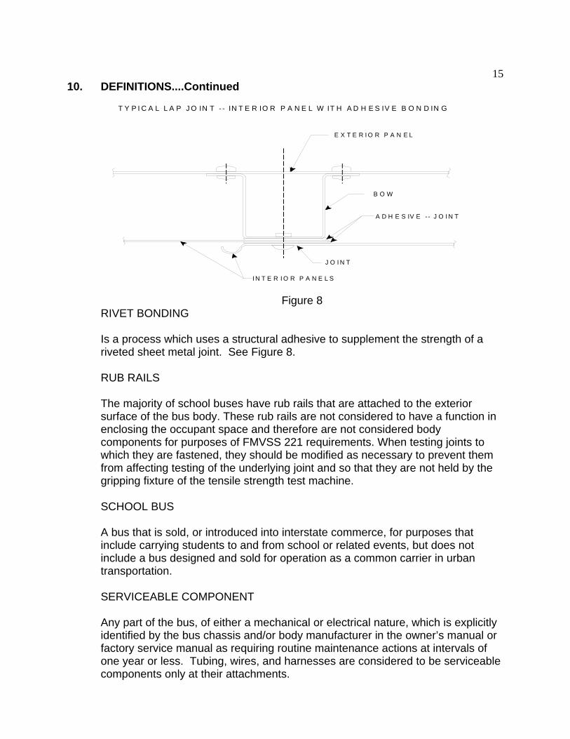
Figure 8 RIVET BONDING
Is a process which uses a structural adhesive to supplement the strength of a riveted sheet metal joint. See Figure 8.
RUB RAILS
The majority of school buses have rub rails that are attached to the exterior surface of the bus body. These rub rails are not considered to have a function in enclosing the occupant space and therefore are not considered body components for purposes of FMVSS 221 requirements. When testing joints to which they are fastened, they should be modified as necessary to prevent them from affecting testing of the underlying joint and so that they are not held by the gripping fixture of the tensile strength test machine.
SCHOOL BUS
A bus that is sold, or introduced into interstate commerce, for purposes that include carrying students to and from school or related events, but does not include a bus designed and sold for operation as a common carrier in urban transportation.
SERVICEABLE COMPONENT
Any part of the bus, of either a mechanical or electrical nature, which is explicitly identified by the bus chassis and/or body manufacturer in the owner’s manual or factory service manual as requiring routine maintenance actions at intervals of one year or less. Tubing, wires, and harnesses are considered to be serviceable components only at their attachments.
16 10. DEFINITIONS....Continued
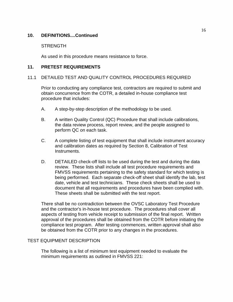
STRENGTH
As used in this procedure means resistance to force.
11. PRETEST REQUIREMENTS
11.1 DETAILED TEST AND QUALITY CONTROL PROCEDURES REQUIRED
Prior to conducting any compliance test, contractors are required to submit and obtain concurrence from the COTR, a detailed in-house compliance test procedure that includes:
A. A step-by-step description of the methodology to be used.
B. A written Quality Control (QC) Procedure that shall include calibrations, the data review process, report review, and the people assigned to perform QC on each task.
C. A complete listing of test equipment that shall include instrument accuracy and calibration dates as required by Section 8, Calibration of Test Instruments.
D. DETAILED check-off lists to be used during the test and during the data review. These lists shall include all test procedure requirements and FMVSS requirements pertaining to the safety standard for which testing is being performed. Each separate check-off sheet shall identify the lab, test date, vehicle and test technicians. These check sheets shall be used to document that all requirements and procedures have been complied with. These sheets shall be submitted with the test report.
There shall be no contradiction between the OVSC Laboratory Test Procedure and the contractor's in-house test procedure. The procedures shall cover all aspects of testing from vehicle receipt to submission of the final report. Written approval of the procedures shall be obtained from the COTR before initiating the compliance test program. After testing commences, written approval shall also be obtained from the COTR prior to any changes in the procedures.
TEST EQUIPMENT DESCRIPTION
The following is a list of minimum test equipment needed to evaluate the minimum requirements as outlined in FMVSS 221:
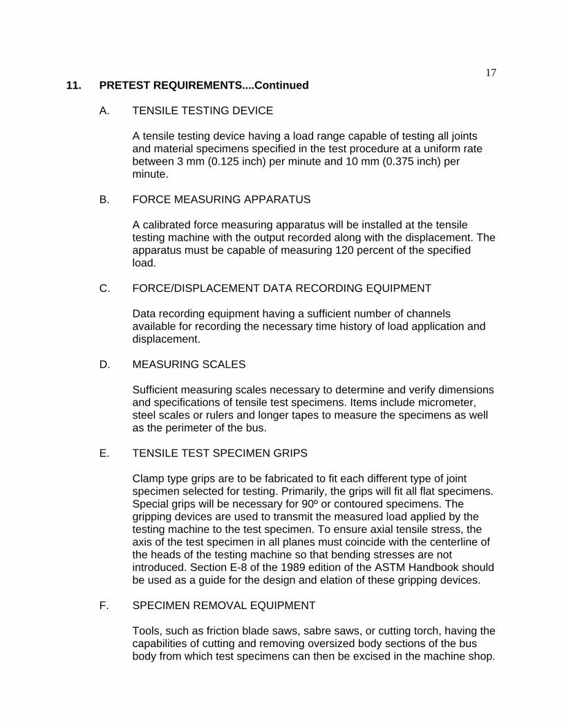
17 11. PRETEST REQUIREMENTS....Continued
A. TENSILE TESTING DEVICE
A tensile testing device having a load range capable of testing all joints and material specimens specified in the test procedure at a uniform rate between 3 mm (0.125 inch) per minute and 10 mm (0.375 inch) per minute.
B. FORCE MEASURING APPARATUS
A calibrated force measuring apparatus will be installed at the tensile testing machine with the output recorded along with the displacement. The apparatus must be capable of measuring 120 percent of the specified load.
C. FORCE/DISPLACEMENT DATA RECORDING EQUIPMENT
Data recording equipment having a sufficient number of channels available for recording the necessary time history of load application and displacement.
D. MEASURING SCALES
Sufficient measuring scales necessary to determine and verify dimensions and specifications of tensile test specimens. Items include micrometer, steel scales or rulers and longer tapes to measure the specimens as well as the perimeter of the bus.
E. TENSILE TEST SPECIMEN GRIPS
Clamp type grips are to be fabricated to fit each different type of joint specimen selected for testing. Primarily, the grips will fit all flat specimens. Special grips will be necessary for 90º or contoured specimens. The gripping devices are used to transmit the measured load applied by the testing machine to the test specimen. To ensure axial tensile stress, the axis of the test specimen in all planes must coincide with the centerline of the heads of the testing machine so that bending stresses are not introduced. Section E-8 of the 1989 edition of the ASTM Handbook should be used as a guide for the design and elation of these gripping devices.
F. SPECIMEN REMOVAL EQUIPMENT
Tools, such as friction blade saws, sabre saws, or cutting torch, having the capabilities of cutting and removing oversized body sections of the bus body from which test specimens can then be excised in the machine shop.

18 11. PRETEST REQUIREMENTS....Continued
It is essential to avoid distortion and excessive temperatures during this operation. Temperature indicating devices must be applied to the body panels at the joint locations before removal from the body to assure that the body panel's temperature never exceeds 140°F.
G. MACHINE SHOP FACILITIES
Facilities capable of cutting and shaping the test specimen to the requirements of this test procedure. To avoid damage to the joint where adhesives are used, the joint must be reinforced with wood blocks and/or clamps and an abrasive coated band saw blade should be used during this final cutting and shaping operation.
TEST EQUIPMENT ACCURACY
ITEM RANGE ACCURACY
Tensile Testing Device 0 to 454 kg (1000 lbs) ± 0.5% Full Scale (Must be calibrated in accordance with Method E-4, Verification of Testing Machines of the American Society for Testing and Materials (1989 Annual Book of ASTM Standards))
0 to 4,536 kg (10,000 lbs)
0 to 22,680 kg (50,000 lbs)
0 to 45,359 kg (100,000 lbs)
0 to 90,718 kg (200,000 lbs)
Continuous Recorder Readout Capability of ± 2% (Load/Deflection/Rate) 5% of maximum load
12 inch steel rule 0 to 12 inches ± 0.0050 inch
Steel tape 0 to 100 feet ± 0.10 inch
Micrometer 0 to 0.999 inches ± 0.0005 inch
H. PHOTOGRAPHIC EQUIPMENT
Photographic equipment necessary to provide a permanent record by illustrating test setup, conduct of test, mode of failure, required interior and exterior views of the test vehicle, etc.
SEQUENCE FOR TESTING
The test shall be conducted in the order shown below:
A. Perform an inspection of the school bus upon receipt

19 11. PRETEST REQUIREMENTS....Continued
T Y P IC A L S C H O O L B U S IL L U S T R A T IO N S H O W IN G C O N S T R U C T IO N D E T A IL S
Figure 9
B. Selection of joints to be tested with the aid of the COTR
C. Preparation of test specimen
D. Conduct tensile tests of specimens
E. Inspection of joints not tensile tested for fastener spacing requirement
F. Analysis of joint strength by calculation
SELECTION OF JOINTS TO BE TESTED
Figure 9 is an illustration showing details of a typical school bus body that has unitized construction and is made of steel. It should be noted that there are numerous and varied joints on the interior and exterior surfaces that are covered by the standard's requirements. A detailed inspection must be made of all accessible panels to determine if there are joints that are suspect of not meeting the requirements. If necessary, floor coverings, access panels, moldings, trim panels, etc., will be removed to allow for an adequate inspection and determination on the adequacy of each joint. Some of these joints cannot be tested in a tensile test machine, as required, because there is not sufficient surrounding material to obtain a satisfactory specimen (meeting the dimensional requirements of Figures 6 and 7) for compliance testing. These types of joints will be reviewed by the test laboratory and COTR and any that appear suspect of insufficient strength will be evaluated by a suitable calculation method by the test laboratory. All joints will be inspected to determine if they meet the fastener spacing requirement. Joints that are suspect of having insufficient strength characteristics or fastener spacing will be reported to the COTR by telephone and then on the Notice of Possible Noncompliance Form. In addition, the test laboratory, after consultation with the COTR, will select six (6) joints for tensile testing from the following locations on the bus body:
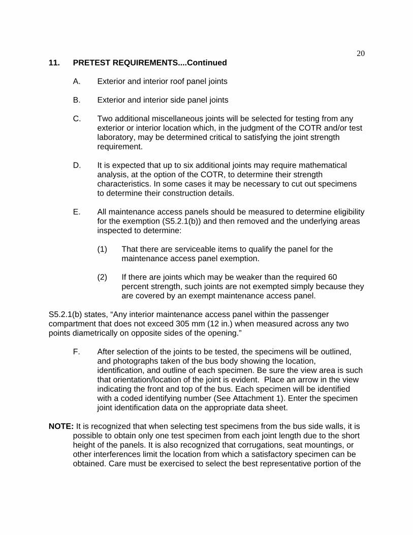
20 11. PRETEST REQUIREMENTS....Continued
A. Exterior and interior roof panel joints
B. Exterior and interior side panel joints
C. Two additional miscellaneous joints will be selected for testing from any exterior or interior location which, in the judgment of the COTR and/or test laboratory, may be determined critical to satisfying the joint strength requirement.
D. It is expected that up to six additional joints may require mathematical analysis, at the option of the COTR, to determine their strength characteristics. In some cases it may be necessary to cut out specimens to determine their construction details.
E. All maintenance access panels should be measured to determine eligibility for the exemption (S5.2.1(b)) and then removed and the underlying areas inspected to determine:
(1) That there are serviceable items to qualify the panel for the maintenance access panel exemption.
(2) If there are joints which may be weaker than the required 60 percent strength, such joints are not exempted simply because they are covered by an exempt maintenance access panel.
S5.2.1(b) states, “Any interior maintenance access panel within the passenger compartment that does not exceed 305 mm (12 in.) when measured across any two points diametrically on opposite sides of the opening.”
F. After selection of the joints to be tested, the specimens will be outlined, and photographs taken of the bus body showing the location, identification, and outline of each specimen. Be sure the view area is such that orientation/location of the joint is evident. Place an arrow in the view indicating the front and top of the bus. Each specimen will be identified with a coded identifying number (See Attachment 1). Enter the specimen joint identification data on the appropriate data sheet.
NOTE: It is recognized that when selecting test specimens from the bus side walls, it is possible to obtain only one test specimen from each joint length due to the short height of the panels. It is also recognized that corrugations, seat mountings, or other interferences limit the location from which a satisfactory specimen can be obtained. Care must be exercised to select the best representative portion of the

21 11. PRETEST REQUIREMENTS....Continued
joint to use for the test specimen. On the roof, ceiling, and other areas where assembled panels form longer joints, good judgment must be used to select joint specimens that appear to represent the overall construction characteristics of the entire joint length. Caution must also be exercised in the selection process to avoid taking specimens from areas that have been stressed due to previous FMVSS tests, or contain mounting holes, lights, grills, etc. or any items that might affect the transfer of forces in the test specimen during the tensile strength test.
REMOVAL OF A BODY SECTION AND TEST SPECIMEN PREPARATION
Cut a body section of approximately 18 x 54 inches (as shown in Figure 10) from which the finished test specimen can be fabricated (as shown in Figure 11). Where a body section containing the joint selected for testing is constructed so that exterior and interior panels are fastened to a common bow, header, stringer, etc., the section must be removed from the bus body as an assembly. The assembly will include both exterior and interior panels fastened as an integral part of the body panel joint as shown in Figure 11. (Exterior rub rails may be included as part of the joint). Apply 140º F temperature sensitive stickers at the 4 locations around the specimen joint area as shown on Figure 10. They should remain on the specimen throughout the entire cutting, shaping and testing process to show that the temperature of 140º F was never exceeded. During the cutting, shaping and transfer operations of the body section or test specimen, exercise extreme care not to flex the joint in any manner in order to preserve the integrity of the joint. For joints which appear to contain adhesives, additional precautions must be taken before starting the body section removal. Install two 1 x 1 x 0.125 inch aluminum angles or wood supports across the joint and attach them to the panels, as shown in Figure 10, to prevent flexing of the joint. Be sure to shim as necessary to clear the panel ribs or irregular surfaces. It is important that the sheet metal screws attaching the angles to the test specimen are located a minimum of 6 inches away from the joint. The support angles must be removed after the specimen is installed in the tensile testing device and before actual testing begins. If it is not possible to cut out a body section of 18 x 54 inches, it is permissible to obtain any width greater than 8 inches and any length greater than the necked down portion as shown in Figure 6 and long enough to allow proper clamping in the grips of the tensile testing machine. The radius of the necked down section must always be equal to or greater than the joint length.
The selected test specimen will be cut from the body section such that it contains an 8” segment of the joint together with a portion of the bus body, in accordance with dimensions shown in Figure 6. Mark the removed end pieces of the joint with the joint number and save for future reference in case it is necessary to compare the before and after test assemblies.
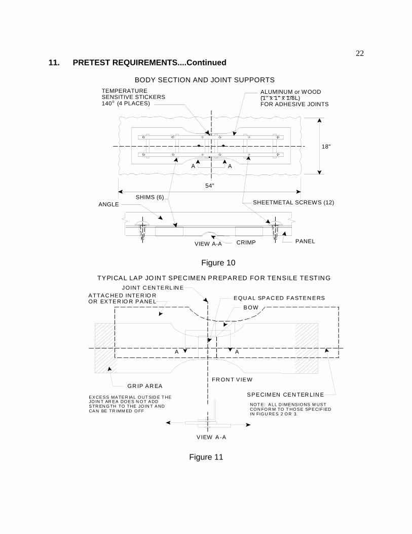
22 11. PRETEST REQUIREMENTS....Continued
BODY SECTION AND JOINT SUPPORTS
140 (o
A(
18"
54"
A
ANGLE
PANEL
) (
A
TEMPERATURE SENSITIVE STICKERS
4 PLACES)
LUMINUM or WOOD SUPPORTS 1" x 1" x 1/8L) FOR ADHESIVE JOINTS
CRIMP VIEW A-A
SHIMS (6SHEETMETAL SCREWS 12)
Figure 10
TYPICAL LAP JO INT SPECIMEN PREPARED FO R TENSILE TESTING
A A
GR IP AR EA FR ON T V IEW
SPECIM EN CEN TER LIN E
BOW
EQU AL SPAC ED FASTEN ERS
JOINT C EN TERL IN E ATTAC HED INTER IO R OR EXTER IO R PANEL
NOT E : A LL D IMENSIO NS M UST CON FO R M TO T HO SE SPE CIF IED IN FIG U RES 2 O R 3.
EX CE SS MA TE R IAL O UT SID E T HE JO IN T AR EA DO ES N O T ADD STR EN G TH TO THE JO IN T A ND CA N BE TR IMM ED OFF
V IEW A-A
Figure 11
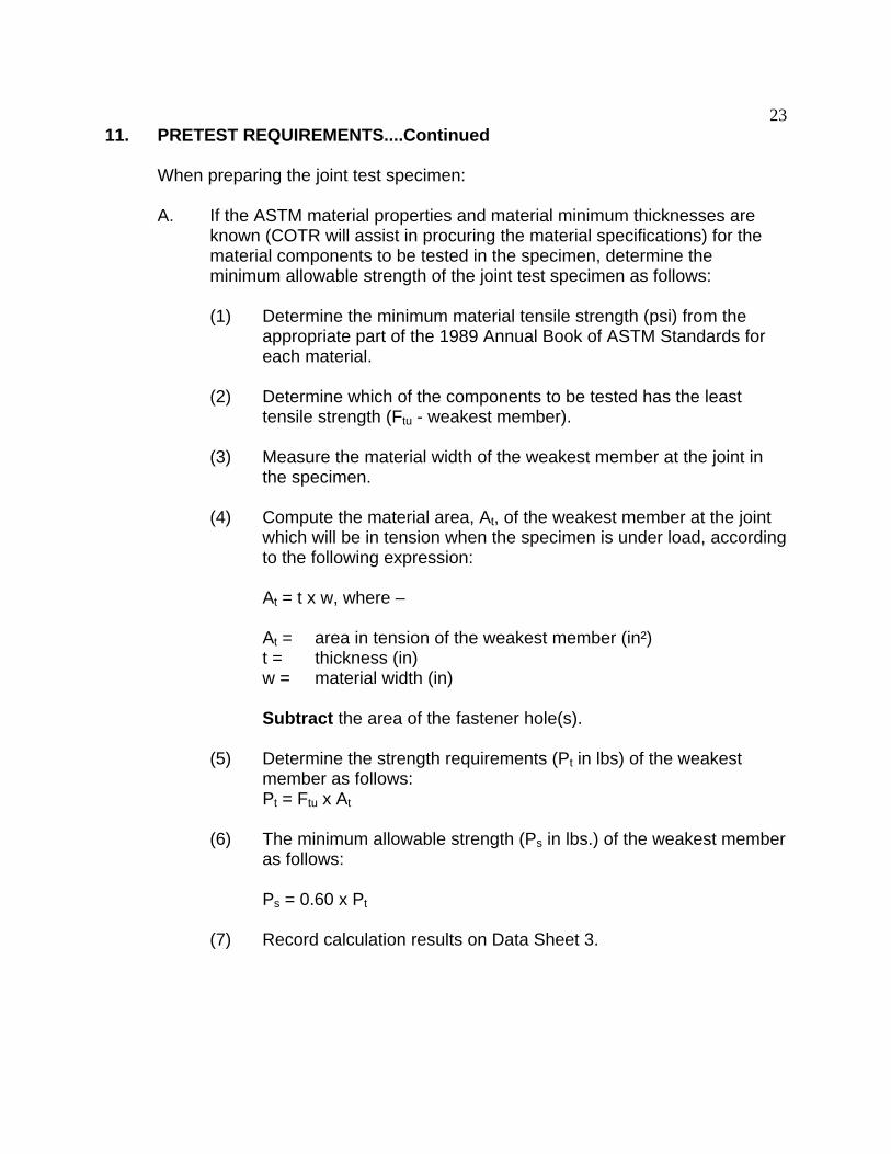
23 11. PRETEST REQUIREMENTS....Continued
When preparing the joint test specimen:
A. If the ASTM material properties and material minimum thicknesses are known (COTR will assist in procuring the material specifications) for the material components to be tested in the specimen, determine the minimum allowable strength of the joint test specimen as follows:
(1) Determine the minimum material tensile strength (psi) from the appropriate part of the 1989 Annual Book of ASTM Standards for each material.
(2) Determine which of the components to be tested has the least tensile strength (Ftu - weakest member).
(3) Measure the material width of the weakest member at the joint in the specimen.
(4) Compute the material area, At, of the weakest member at the joint which will be in tension when the specimen is under load, according to the following expression:
At = t x w, where –
At = area in tension of the weakest member (in²) t = thickness (in) w = material width (in)
Subtract the area of the fastener hole(s).
(5) Determine the strength requirements (Pt in lbs) of the weakest member as follows: Pt = Ftu x At
(6) The minimum allowable strength (Ps in lbs.) of the weakest member as follows:
Ps = 0.60 x Pt
(7) Record calculation results on Data Sheet 3.

24 11. PRETEST REQUIREMENTS....Continued
TYPICAL TEST SPECIMEN
JOINT CENTERLINE
7 EQUAL SPACED FASTENERS
SPECIMEN CENTERLINE ASTM A-7 16 GA. SHEET
P P 8"
1/2" MIN. (TYP.)
ASTM A-7 22 GA. SHEET
DIRECTION OF LOAD
FRONT VIEW
Figure 12
The following is a sample calculation of a typical test specimen that is prepared for testing in the tensile test machine:
(1) Minimum ultimate tensile strength (FTU) of ASTM A7 steel is 45,000 psi:
Ftu = 45,000 psi
(2) Minimum thickness of 22 gauge sheet is 0.0296 inches.
(3) Minimum thickness of 16 gauge sheet is 0.0575 inches.
(4) Use thickness of 22 gauge sheet (weakest member) in computing
At:
w = (width of sample) – (no. of fasteners x diameter) = 8” – (7x0.1”)
At = t x w = 0.0296 in. x 7.3 in. = 0.216 in²

25 11. PRETEST REQUIREMENTS....Continued
(5) The allowable strength (Pt) of the weakest member is calculated by substituting in the equation:
Pt = Ftu x At
Pt = 45,000 psi x 0.216 in²
Pt = 9,723 pounds
(6) The minimum allowable strength (Ps) of the joint shall be at least 60 percent of the strength (Pt) of the material in the weakest component of the test specimen.
Ps = 0.60 x Pt
Ps = 0.60 x 9,723 lbs
Ps = 5,834 pounds
(7) The test specimen must be capable of withstanding at least Ps = 5,834 pounds before separation of the joint occurs.
B. If the ASTM material properties and thicknesses are NOT known for the material components to be tested in the test specimen, the minimum allowable strength for that joint will be determined as follows:
(1) Measure the material thickness of each material that will be tensile tested.
(2) The thinnest material will be identified as the weakest member and its tensile strength will be determined.
(3) Cut 2 specimens of the weakest member material from the school bus body in an area outside the joint specimen and machine them to the dimensions shown in Figure 8.
(4) Determine the tensile strength (Ftu) of that material in accordance with the procedures outlined in Method E8-89, “Standard Test Methods of Tension Testing of Metallic Materials,” of the 1989 Annual Book of ASTM Standards.
(5) Record calculation results on Data Sheet 5.

26 11. PRETEST REQUIREMENTS....Continued
(6) Using the average tensile strength determined above, compute the minimum allowable strength of the selected joint in accordance with the procedures described in Item A. 1 - 7 above.
(7) Record calculation results on Data Sheet 4.
C. Cut out the test specimen from the previously selected body section in accordance with Figures 6 or 7 as applicable. For body sections containing adhesive joints, the aluminum angle supports are not to be removed during the test specimen shaping operation and care is to be exercised in handling the body section and the specimen to preclude flexing of the joint.
D. Where a body panel joint is not fastened continuously, i.e., discrete fasteners do not occur at equally spaced intervals across the midpoint of the joint segment, the joint will be cut out and machined so that a spot weld or discrete fastener is not bisected. Good judgment must also be exercised to center the fastener pattern in the test joint section as closely as possible.
E. When cutting out and machining the selected test specimens, care must be taken to prevent distortion, excessive vibrations or excessive temperatures of any joint components. A special grit-edge tungsten carbide continuous grit band saw blade, when used for the final shaping of the 8 inch straight section across the specimen joint area, will minimize vibration during the cutting operation. On body sections containing adhesive joints, special blocks will be applied prior to starting the band saw cut. Wood blocks will be inserted below the joint panels and attached to each panel with screws and/or adhesives to further minimize vibration generation during the band saw cutting operation. (See Figure 13)
F. Obtain suitable tensile test machine grips capable of holding each test specimen in the tensile test machine. It is permissible to drill or punch holes at the end of the specimen to allow for bolts to go through the specimen and clamp the grips of the tensile test machine together.
G. Install and align the selected test specimen in the tensile test machine, which has been calibrated in accordance with the procedures outlined in Method E4-89, “Standard Practices for Load Verification of Testing Machines,” of the 1989 Annual Book of ASTM Standards.

27 11. PRETEST REQUIREMENTS....Continued
APPLICATION OF WOOD BLOCKS TO SPECIMENS CONTAINING ADHESIVE JOINTS (TYPICAL)
8"
()
WOOD BLOCKS
CUT WITH BANDSAW STARTING HERE
BLOCK ATTACHING SCREWS
CUT WITH BANDSAW NO ADHESIVE BEYO ND
THE CUT LINE
Figure 13
H. Photograph the test setup with the specimen installed in the tensile test machine for each test specimen.
I. Prepare a sketch of each test specimen showing details of the joint selected for testing. The sketch should include all specimen dimensions and material identifications, thicknesses, description of fasteners, and tensile strength of the components to be tested. In addition, the sketch will illustrate which joint components are being pulled in the tensile test machine. This sketch will also be attached to the data sheet used for each test specimen.
CAUTION: Extreme care must be exercised at all times when handling the body section and the test specimen to avoid damage to the joint section.
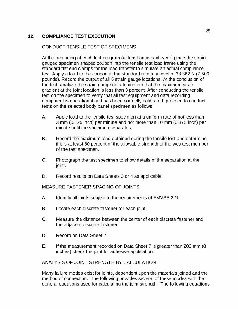
28 12. COMPLIANCE TEST EXECUTION
CONDUCT TENSILE TEST OF SPECIMENS
At the beginning of each test program (at least once each year) place the strain gauged specimen shaped coupon into the tensile test load frame using the standard flat end clamps for the load transfer to simulate an actual compliance test. Apply a load to the coupon at the standard rate to a level of 33,362 N (7,500 pounds). Record the output of all 5 strain gauge locations. At the conclusion of the test, analyze the strain gauge data to confirm that the maximum strain gradient at the joint location is less than 3 percent. After conducting the tensile test on the specimen to verify that all test equipment and data recording equipment is operational and has been correctly calibrated, proceed to conduct tests on the selected body panel specimen as follows:
A. Apply load to the tensile test specimen at a uniform rate of not less than 3 mm (0.125 inch) per minute and not more than 10 mm (0.375 inch) per minute until the specimen separates.
B. Record the maximum load obtained during the tensile test and determine if it is at least 60 percent of the allowable strength of the weakest member of the test specimen.
C. Photograph the test specimen to show details of the separation at the joint.
D. Record results on Data Sheets 3 or 4 as applicable.
MEASURE FASTENER SPACING OF JOINTS
A. Identify all joints subject to the requirements of FMVSS 221.
B. Locate each discrete fastener for each joint.
C. Measure the distance between the center of each discrete fastener and the adjacent discrete fastener.
D. Record on Data Sheet 7.
E. If the measurement recorded on Data Sheet 7 is greater than 203 mm (8 inches) check the joint for adhesive application.
ANALYSIS OF JOINT STRENGTH BY CALCULATION
Many failure modes exist for joints, dependent upon the materials joined and the method of connection. The following provides several of these modes with the general equations used for calculating the joint strength. The following equations

29 12. COMPLIANCE TEST EXECUTION…Continued
do not encompass all possible joints, an appropriate steel design textbook that references the American Institute of Steel Construction’s Load and Resistance Factor Design specification (AISC LRFD), should be consulted for completeness and accuracy of the calculations necessary for any particular type of joint. The equations listed are from this specification. If materials other than steel are used consult the appropriate resource to determine the proper calculations. Consult with the COTR for approval of the equations and methods used to calculate the joint strength. Record calculation results on Data Sheet 6.
A. Fracture of effective net area
P = A F n u e
Where:
P = Strengthn
F = Tensile Strength of Connected Memberu
A = Net effective area [(Width of the plate minus (the number of e
fasteners multiplied by the fastener diameter plus 1/8”)) multiplied by the thickness of the plate]
If the fasteners are staggered the net effective area is calculated using a different equation that accounts for the stagger and spacing of the fasteners. Consult AISC LRFD for the appropriate equation.
B. Block Shear (Plate Tearing Limit State)
There are two modes for block shear failure, depending on the values calculated the failure mode is either shear yielding-tension fracture or shear fracture-tension yielding. This failure mode frequently controls in joints with thin plates, such as school bus body joints. Depending on the arrangement of fasteners there could be several different block shear paths. Consult AISC LRFD and/or a steel design textbook for further guidance on calculating block shear.
Shear yielding-Tension fracture controls if ( A F ≥ 6.0 A F )u nt u nv
P = 6.0 A F gv + A F ntn y u
Shear fracture-Tension yielding controls if ( A F < 6.0 A F )u nt u nv
P = 6. 0 A F + A F gtn u nv y
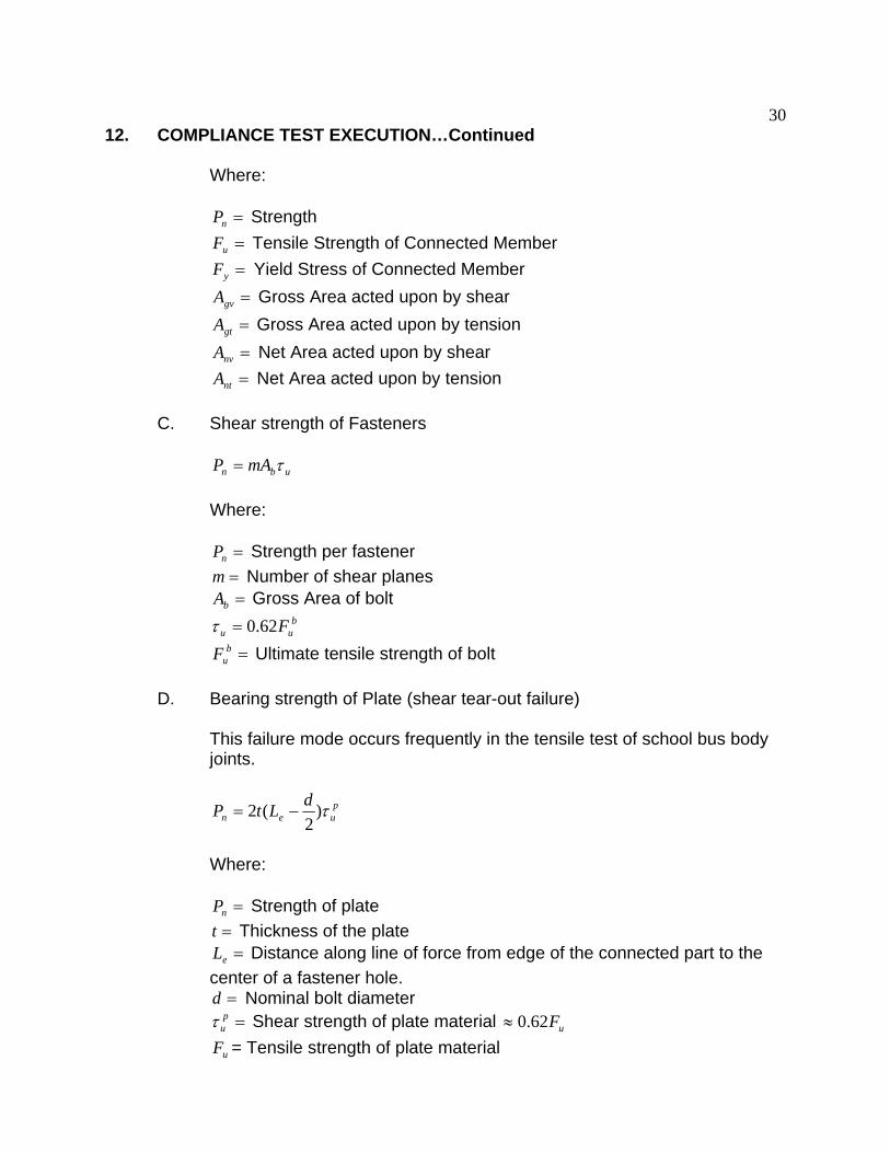
30 12. COMPLIANCE TEST EXECUTION…Continued
Where:
P = Strengthn
F = Tensile Strength of Connected Memberu
F = Yield Stress of Connected Member y
A = Gross Area acted upon by shear A
gv
gt = Gross Area acted upon by tension A = Net Area acted upon by shear A
nv
nt = Net Area acted upon by tension
C. Shear strength of Fasteners
P = mA τn u b
Where:
P = Strength per fastenern
m = Number of shear planes Ab = Gross Area of bolt
bτ = 62.0 F F
u u
b = Ultimate tensile strength of bolt u
D. Bearing strength of Plate (shear tear-out failure)
This failure mode occurs frequently in the tensile test of school bus body joints.
P = 2 L t − d )τ p(n e u2
Where:
P = Strength of platen
t = Thickness of the plate L = Distance along line of force from edge of the connected part to the e
τ
center of a fastener hole. d = Nominal bolt diameter
p = Shear strength of plate material ≈ 62.0 Fu u
F = Tensile strength of plate material u

31 12. COMPLIANCE TEST EXECUTION…Continued
NOTE: The use of adhesives at the joint may increase the strength of the joint and would require additional calculations from data supplied by the manufacturer.
13. POSTTEST REQUIREMENTS
The contractor shall re-verify all instrumentation and check data sheets and photographs.
A. Protect the school bus from further damage and the elements
B. Move the school bus to a secure area
C. Prepare the final test report
13.1 TEST DATA LOSS
A. INVALID TEST
An invalid compliance test is one that does not conform precisely to all requirements/specifications of the OVSC Laboratory Test Procedure and Statement of Work applicable to the test.
B. INVALID TEST NOTIFICATION
The contractor shall notify NHTSA of any test not meeting all requirements/specifications of the OVSC Laboratory Test Procedure and Statement of Work applicable to the test, by telephone, within 24 hours of the test and send written notice to the COTR within 48 hours of the test completion.
C. RETEST NOTIFICATION
The Contracting Officer of NHTSA is the only NHTSA official authorized to notify the Contractor that a retest is required. The retest shall be completed within 2 weeks after receipt of notification by the Contracting Officer that a retest is required.
D. WAIVER OF RETEST
NHTSA, in its sole discretion, reserves the right to waive the retest requirement. This provision shall not constitute a basis for dispute over the NHTSA's waiving or not waiving any requirement.

32 13. POSTTEST REQUIREMENTS…Continued
E. TEST VEHICLE
NHTSA shall furnish only one vehicle for each test ordered. The contractor shall furnish the test vehicle required for the retest. The retest vehicle shall be equipped as the original vehicle. The original vehicle used in the invalid test shall remain the property of NHTSA and the retest vehicle shall remain the property of the contractor. The contractor shall retain the retest vehicle for a period not exceeding 180 days if it fails the test. If the retest vehicle passes the test, the contractor may dispose of it upon notification from the COTR that the test report has been accepted.
F. TEST REPORT
No test report is required for any test that is determined to be invalid unless NHTSA specifically decides, in writing, to require the contractor to submit such report. The test data from the invalid test must be safeguarded until the data from the retest has been accepted by the COTR. The report and other required deliverables for the retest vehicle are required to be submitted to the COTR within 3 weeks after completion of the retest.
G. DEFAULT
The contractor is subject to default and subsequent procurement costs for non-delivery of a valid or conforming test (pursuant to the Termination For Default clause in the contract).
H. NHTSA'S RIGHTS
None of the requirements herein stated shall diminish or modify the rights of NHTSA to determine that any test submitted by the contractor does not conform precisely to all requirements/specifications of the OVSC Laboratory Test Procedure and Statement of Work applicable to the test.
REPORTING OF POSSIBLE NONCOMPLIANCE
A. The following conditions shall be classified as possible noncompliance:
(1) Any defect noted in the test vehicle which indicates an obvious violation of any FMVSS requirements.
(2) Any condition discovered during the compliance test that indicates the test vehicle fails to meet any of the requirements of FMVSS 221.
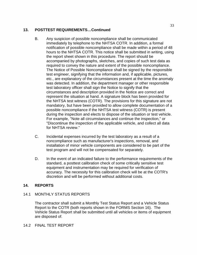
33 13. POSTTEST REQUIREMENTS…Continued
B. Any suspicion of possible noncompliance shall be communicated immediately by telephone to the NHTSA COTR. In addition, a formal notification of possible noncompliance shall be made within a period of 48 hours to the NHTSA COTR. This notice shall be submitted in writing, using the report sheet shown in this procedure. The report should be accompanied by photographs, sketches, and copies of such test data as required to convey the nature and extent of the possible noncompliance. The Notice of Possible Noncompliance shall be signed by the responsible test engineer, signifying that the information and, if applicable, pictures, etc., are explanatory of the circumstances present at the time the anomaly was detected. In addition, the department manager or other responsible test laboratory officer shall sign the Notice to signify that the circumstances and description provided in the Notice are correct and represent the situation at hand. A signature block has been provided for the NHTSA test witness (COTR). The provisions for this signature are not mandatory, but have been provided to allow complete documentation of a possible noncompliance if the NHTSA test witness (COTR) is present during the inspection and elects to dispose of the situation or test vehicle. For example, "Note all circumstances and continue the inspection," or "Discontinue the inspection of the applicable vehicle, and collect all data for NHTSA review."
C. Incidental expenses incurred by the test laboratory as a result of a noncompliance such as manufacturer's inspections, removal, and installation of minor vehicle components are considered to be part of the test program and will not be compensated for separately.
D. In the event of an indicated failure to the performance requirements of the standard, a posttest calibration check of some critically sensitive test equipment and instrumentation may be required for verification of accuracy. The necessity for this calibration check will be at the COTR's discretion and will be performed without additional costs.
14. REPORTS
14.1 MONTHLY STATUS REPORTS
The contractor shall submit a Monthly Test Status Report and a Vehicle Status Report to the COTR (both reports shown in the FORMS Section 16). The Vehicle Status Report shall be submitted until all vehicles or items of equipment are disposed of.
14.2 FINAL TEST REPORT
34 14. REPORTS…Continued
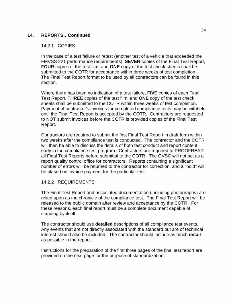
14.2.1 COPIES
In the case of a test failure or retest (another test of a vehicle that exceeded the FMVSS 221 performance requirements), SEVEN copies of the Final Test Report, FOUR copies of the test film, and ONE copy of the test check sheets shall be submitted to the COTR for acceptance within three weeks of test completion. The Final Test Report format to be used by all contractors can be found in this section.
Where there has been no indication of a test failure, FIVE copies of each Final Test Report, THREE copies of the test film, and ONE copy of the test check sheets shall be submitted to the COTR within three weeks of test completion. Payment of contractor's invoices for completed compliance tests may be withheld until the Final Test Report is accepted by the COTR. Contractors are requested to NOT submit invoices before the COTR is provided copies of the Final Test Report.
Contractors are required to submit the first Final Test Report in draft form within two weeks after the compliance test is conducted. The contractor and the COTR will then be able to discuss the details of both test conduct and report content early in the compliance test program. Contractors are required to PROOFREAD all Final Test Reports before submittal to the COTR. The OVSC will not act as a report quality control office for contractors. Reports containing a significant number of errors will be returned to the contractor for correction, and a "hold" will be placed on invoice payment for the particular test.
14.2.2 REQUIREMENTS
The Final Test Report and associated documentation (including photographs) are relied upon as the chronicle of the compliance test. The Final Test Report will be released to the public domain after review and acceptance by the COTR. For these reasons, each final report must be a complete document capable of standing by itself.
The contractor should use detailed descriptions of all compliance test events. Any events that are not directly associated with the standard but are of technical interest should also be included. The contractor should include as much detail as possible in the report.
Instructions for the preparation of the first three pages of the final test report are provided on the next page for the purpose of standardization.

35 14. REPORTS....Continued
14.2.3 FIRST THREE PAGES
FRONT COVER
A heavy paperback cover (or transparency) shall be provided for the protection of the final report. The information required on the cover is as follows:
A. Final Report Number such as 221_ABC_0X_001, where:
221 FMVSS tested ABC initials for the laboratory 0X Fiscal Year of the test program
001 Group Number (001 for the 1st test, 002 for the 2nd test, 003 for the 3rd test, etc.)
B. Final Report Title And Subtitle (example):
SAFETY COMPLIANCE TESTING FOR FMVSS 221 School Bus Body Joint Strength
* * * * * * * * * * * * * * * * * * * World Motors Corporation
200X World XYZ 65-Passenger School Bus NHTSA No. CX0901
C. Contractor's Name and Address (example):
ABC LABORATORIES, INC. 405 Main Street
Detroit, Michigan 48070
NOTE: DOT SYMBOL WILL BE PLACED BETWEEN ITEMS (C) AND (D)
D. Date of Final Report completion
E. The words "FINAL REPORT"
F. The sponsoring agency's name and address as follows –
U. S. DEPARTMENT OF TRANSPORTATION National Highway Traffic Safety Administration
Enforcement Office of Vehicle Safety Compliance
Mail Code: NVS-220, Room 6111 400 Seventh Street, SW Washington, DC 20590

36 14. REPORTS....Continued
FIRST PAGE AFTER FRONT COVER
A disclaimer statement and an acceptance signature block for the COTR shall be provided as follows:
This publication is distributed by the U.S. Department of Transportation, National Highway Traffic Safety Administration, in the interest of information exchange. The opinions, findings and conclusions expressed in this publication are those of the author(s) and not necessarily those of the Department of Transportation or the National Highway Traffic Safety Administration. The United States Government assumes no liability for its contents or use thereof. If trade or manufacturers' names or products are mentioned, it is only because they are considered essential to the object of the publication and should not be construed as an endorsement. The United States Government does not endorse products or manufacturers.
Prepared By:
Approved By:
Approval Date:
FINAL REPORT ACCEPTANCE BY OVSC:
Accepted By:
Acceptance Date:

37 14. REPORTS....Continued
SECOND PAGE AFTER FRONT COVER
A completed Technical Report Documentation Page (Form DOT F1700.7) shall be completed for those items that are applicable with the other spaces left blank. Sample data for the applicable block numbers of the title page follow:
Block 1 — REPORT NUMBER
221_ABC_0X_001
Block 2 — GOVERNMENT ACCESSION NUMBER
Leave blank
Block 3 — RECIPIENT'S CATALOG NUMBER
Leave blank
Block 4 — TITLE AND SUBTITLE
Final Report of FMVSS 221 Compliance Testing of a 200X World XYZ 65-Passenger School Bus
NHTSA No. CX0901
Block 5 — REPORT DATE
March 1, 200X
Block 6 — PERFORMING ORGANIZATION CODE
ABC
Block 7 — AUTHOR(S)
John Smith, Project Manager Bill Doe, Project Engineer
Block 8 — PERFORMING ORGANIZATION REPORT NUMBER
ABC_DOT_XXX_001
38 14. REPORTS....Continued
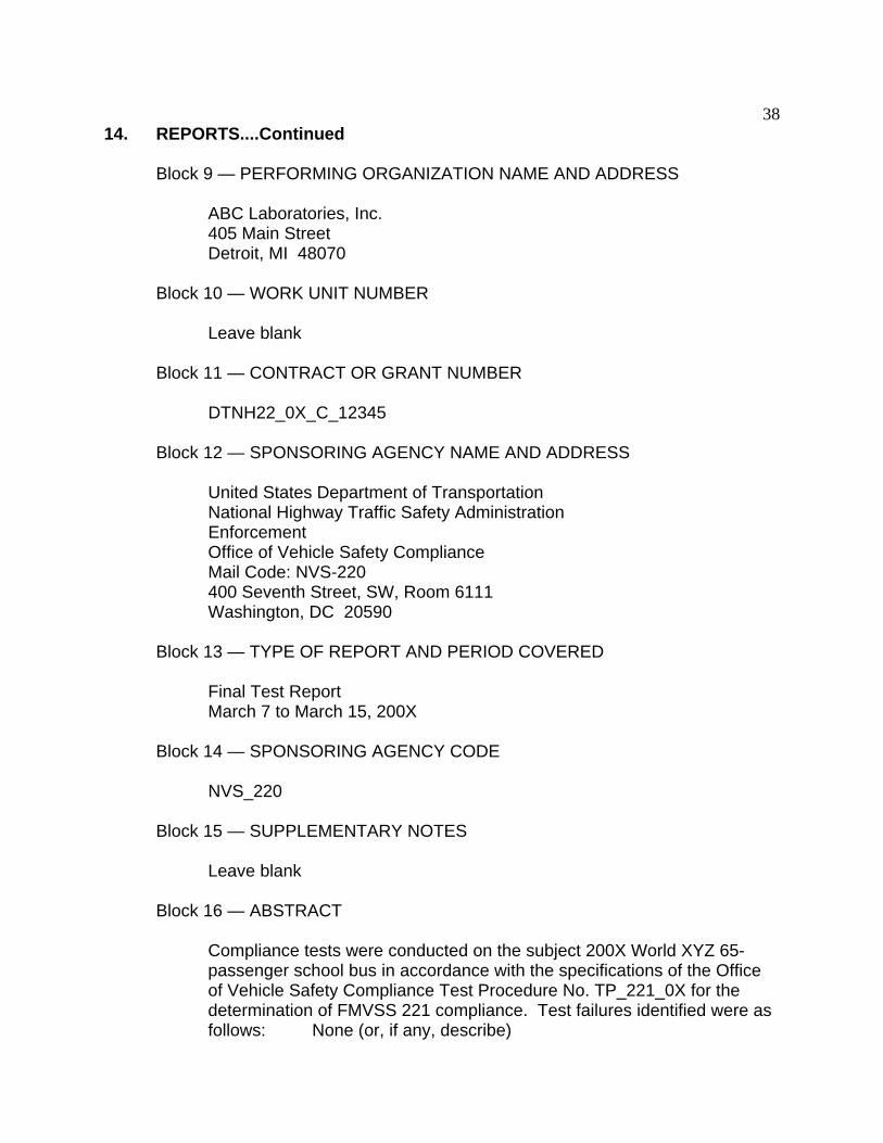
Block 9 — PERFORMING ORGANIZATION NAME AND ADDRESS
ABC Laboratories, Inc. 405 Main Street Detroit, MI 48070
Block 10 — WORK UNIT NUMBER
Leave blank
Block 11 — CONTRACT OR GRANT NUMBER
DTNH22_0X_C_12345
Block 12 — SPONSORING AGENCY NAME AND ADDRESS
United States Department of Transportation National Highway Traffic Safety Administration Enforcement Office of Vehicle Safety Compliance
Mail Code: NVS-220 400 Seventh Street, SW, Room 6111 Washington, DC 20590
Block 13 — TYPE OF REPORT AND PERIOD COVERED
Final Test Report March 7 to March 15, 200X
Block 14 — SPONSORING AGENCY CODE
NVS_220
Block 15 — SUPPLEMENTARY NOTES
Leave blank
Block 16 — ABSTRACT
Compliance tests were conducted on the subject 200X World XYZ 65passenger school bus in accordance with the specifications of the Office of Vehicle Safety Compliance Test Procedure No. TP_221_0X for the determination of FMVSS 221 compliance. Test failures identified were as follows: None (or, if any, describe)

39 14. REPORTS....Continued
Block 17 — KEY WORDS
Compliance Testing Safety Engineering FMVSS 221
Block 18 — DISTRIBUTION STATEMENT
Copies of this report are available from the following:
NHTSA Technical Information Services (TIS) Mail Code: NPO-230
400 Seventh St., SW, Room 5108 Washington, DC 20590 Telephone No. 202-366-4946
Block 19 — SECURITY CLASSIFICATION OF REPORT
Unclassified
Block 20 — SECURITY CLASSIFICATION OF PAGE
Unclassified
Block 21 — NUMBER OF PAGES
Add appropriate number
Block 22 — PRICE
Leave blank
40 14. REPORTS....Continued
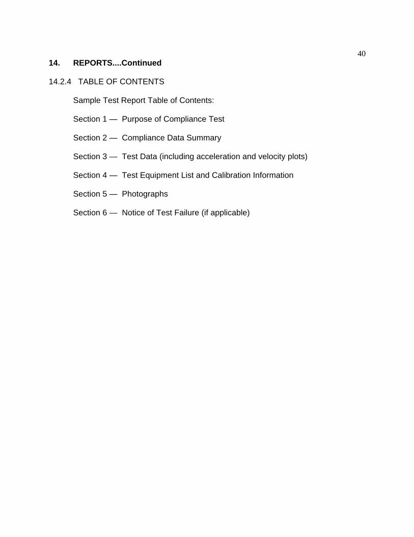
14.2.4 TABLE OF CONTENTS
Sample Test Report Table of Contents:
Section 1 — Purpose of Compliance Test
Section 2 — Compliance Data Summary
Section 3 — Test Data (including acceleration and velocity plots)
Section 4 — Test Equipment List and Calibration Information
Section 5 — Photographs
Section 6 — Notice of Test Failure (if applicable)

41 15. DATA SHEETS
DATA SHEET 1 ADMINISTRATIVE DATA
CONTRACT NO.: DTNH22-_________________________________
LABORATORY NAME: ___________________________________________________
DESCRIPTION OF SCHOOL BUS:
A. Incomplete Vehicle (if applicable)
(1) MFR.: ___________________________________________________________
(2) MODEL: _________________________________________________________
(3) VIN: ____________________________________________________________
(4) BUILD DATE: _____________________________________________________
(5) CERTIFICATION DATE: ____________________________________________
Completed Vehicle (SCHOOL BUS)
(1) MFR.: ___________________________________________________________
(2) MAKE/MODEL: ___________________________________________________
(3) VIN: ____________________________________________________________
(4) NHTSA NO.: _____________________________________________________
(5) COLOR: _________________________________________________________
(6) GVWR: __________________________________________________________
(7) BUILD DATE: _____________________________________________________
(8) CERTIFICATION DATE: ____________________________________________
REMARKS:
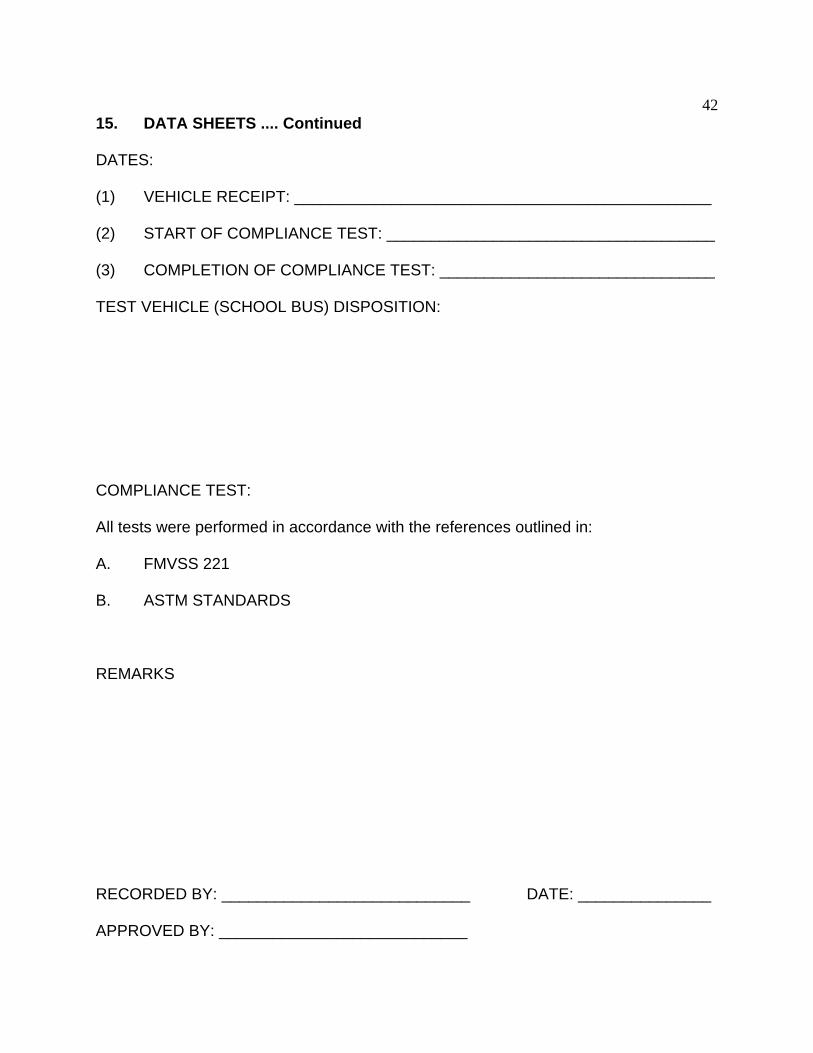
42 15. DATA SHEETS .... Continued
DATES:
(1) VEHICLE RECEIPT: _______________________________________________
(2) START OF COMPLIANCE TEST: _____________________________________
(3) COMPLETION OF COMPLIANCE TEST: _______________________________
TEST VEHICLE (SCHOOL BUS) DISPOSITION:
COMPLIANCE TEST:
All tests were performed in accordance with the references outlined in:
A. FMVSS 221
B. ASTM STANDARDS
REMARKS
RECORDED BY: ____________________________ DATE: _______________
APPROVED BY: ____________________________
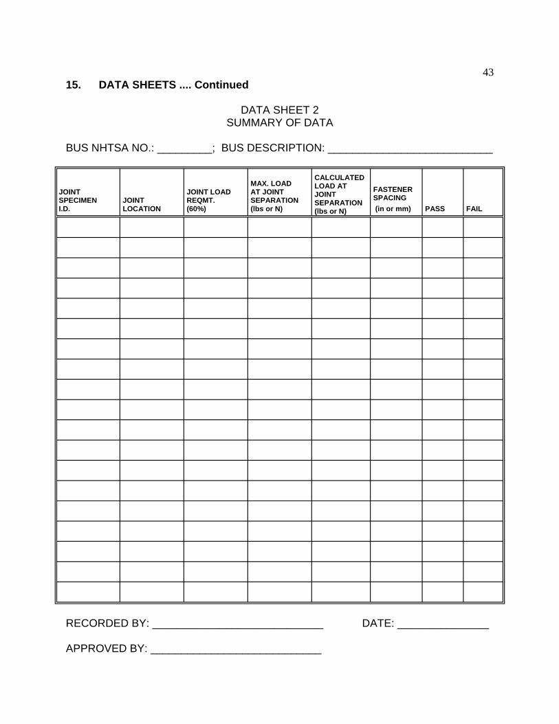
43 15. DATA SHEETS .... Continued
DATA SHEET 2 SUMMARY OF DATA
BUS NHTSA NO.: _________; BUS DESCRIPTION: ___________________________
JOINT SPECIMEN I.D.
JOINT LOCATION
JOINT LOAD REQMT. (60%)
MAX. LOAD AT JOINT SEPARATION (lbs or N)
CALCULATED LOAD AT JOINT SEPARATION (lbs or N)
FASTENER SPACING (in or mm) PASS FAIL
RECORDED BY: ____________________________ DATE: _______________
APPROVED BY: ____________________________
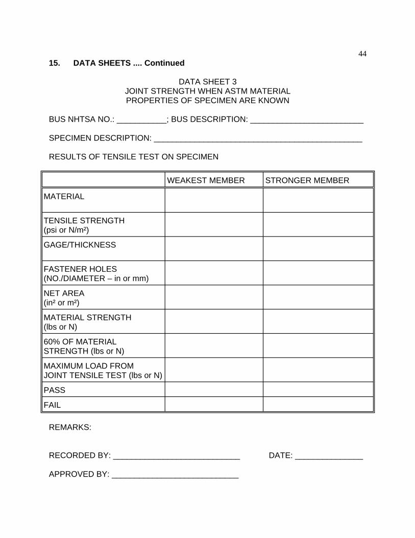
44 15. DATA SHEETS .... Continued
DATA SHEET 3 JOINT STRENGTH WHEN ASTM MATERIAL PROPERTIES OF SPECIMEN ARE KNOWN
BUS NHTSA NO.: ___________; BUS DESCRIPTION: _________________________
SPECIMEN DESCRIPTION: ______________________________________________
RESULTS OF TENSILE TEST ON SPECIMEN
WEAKEST MEMBER STRONGER MEMBER
MATERIAL
TENSILE STRENGTH (psi or N/m²)
GAGE/THICKNESS
FASTENER HOLES (NO./DIAMETER – in or mm)
NET AREA (in² or m²)
MATERIAL STRENGTH (lbs or N)
60% OF MATERIAL STRENGTH (lbs or N)
MAXIMUM LOAD FROM JOINT TENSILE TEST (lbs or N)
PASS
FAIL
REMARKS:
RECORDED BY: ____________________________ DATE: _______________
APPROVED BY: ____________________________
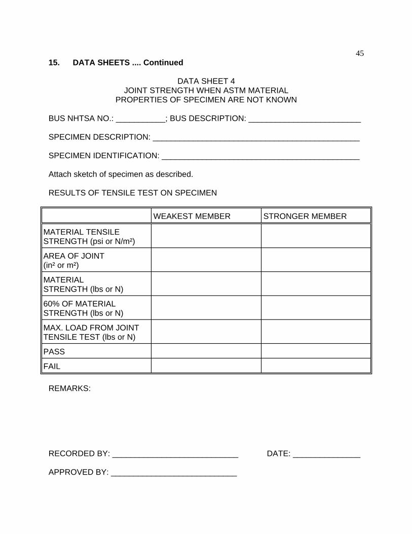
45 15. DATA SHEETS .... Continued
DATA SHEET 4 JOINT STRENGTH WHEN ASTM MATERIAL
PROPERTIES OF SPECIMEN ARE NOT KNOWN
BUS NHTSA NO.: ___________; BUS DESCRIPTION: _________________________
SPECIMEN DESCRIPTION: ______________________________________________
SPECIMEN IDENTIFICATION: ____________________________________________
Attach sketch of specimen as described.
RESULTS OF TENSILE TEST ON SPECIMEN
WEAKEST MEMBER STRONGER MEMBER
MATERIAL TENSILE STRENGTH (psi or N/m²)
AREA OF JOINT (in² or m²)
MATERIAL STRENGTH (lbs or N)
60% OF MATERIAL STRENGTH (lbs or N)
MAX. LOAD FROM JOINT TENSILE TEST (lbs or N)
PASS
FAIL
REMARKS:
RECORDED BY: ____________________________ DATE: _______________
APPROVED BY: ____________________________
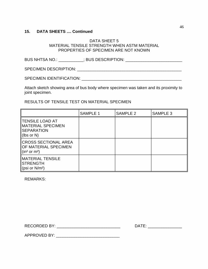
46 15. DATA SHEETS .... Continued
DATA SHEET 5 MATERIAL TENSILE STRENGTH WHEN ASTM MATERIAL
PROPERTIES OF SPECIMEN ARE NOT KNOWN
BUS NHTSA NO.: ___________; BUS DESCRIPTION: _________________________
SPECIMEN DESCRIPTION: ______________________________________________
SPECIMEN IDENTIFICATION: ____________________________________________
Attach sketch showing area of bus body where specimen was taken and its proximity to joint specimen.
RESULTS OF TENSILE TEST ON MATERIAL SPECIMEN
SAMPLE 1 SAMPLE 2 SAMPLE 3
TENSILE LOAD AT MATERIAL SPECIMEN SEPARATION (lbs or N)
CROSS SECTIONAL AREA OF MATERIAL SPECIMEN (in² or m²)
MATERIAL TENSILE STRENGTH (psi or N/m²)
REMARKS:
RECORDED BY: ____________________________ DATE: _______________
APPROVED BY: ____________________________
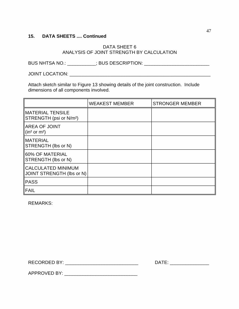
47 15. DATA SHEETS .... Continued
DATA SHEET 6 ANALYSIS OF JOINT STRENGTH BY CALCULATION
BUS NHTSA NO.: ___________; BUS DESCRIPTION: _________________________
JOINT LOCATION: ______________________________________________________
Attach sketch similar to Figure 13 showing details of the joint construction. Include dimensions of all components involved.
WEAKEST MEMBER STRONGER MEMBER
MATERIAL TENSILE STRENGTH (psi or N/m²)
AREA OF JOINT (in² or m²)
MATERIAL STRENGTH (lbs or N)
60% OF MATERIAL STRENGTH (lbs or N)
CALCULATED MINIMUM JOINT STRENGTH (lbs or N)
PASS
FAIL
REMARKS:
RECORDED BY: ____________________________ DATE: _______________
APPROVED BY: ____________________________
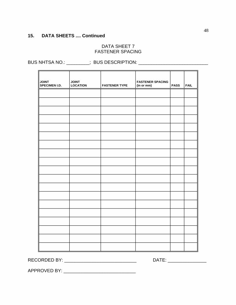
48 15. DATA SHEETS .... Continued
DATA SHEET 7 FASTENER SPACING
BUS NHTSA NO.: _________; BUS DESCRIPTION: ___________________________
JOINT SPECIMEN I.D.
JOINT LOCATION FASTENER TYPE
FASTENER SPACING (in or mm) PASS FAIL
RECORDED BY: ____________________________ DATE: _______________
APPROVED BY: ____________________________

49 15. DATA SHEETS .... Continued
ATTACHMENT 1 – TEST SPECIMEN IDENTIFICATION NUMBER
1 2 3 4 5 6 7 8 9 10 11 12
T S R L F E 1 8 6 A R H
CODES:
1. SCHOOL BUS NAME 6. INTERIOR/EXTERIOR
B. BLUE BIRD I – INTERIOR
I. IC CORP E – EXTERIOR
T. THOMAS 7. SAMPLE NUMBER
M. MIDBUS 1 – FIRST
2 – SECOND
8. JOINT WIDTH (inches)
2. SMALL/LARGE SCHOOL BUS 9. NO. OF FASTENERS (inches)
S – SMALL 10. SPECIMEN TOTAL SIZE
L – LARGE A – 12" WIDE X 24" LONG
3. GENERAL SAMPLE LOCATION B – 12" WIDE X 48" LONG
S – SIDE C – SPECIAL
F – FLOOR 11. JOINT DESCRIPTION
R – ROOF A – ADHESIVE + RIVETS
H – HEADLINER B – ADHESIVE + SCREWS
O – OTHER C – ADHESIVE ONLY
4. LATERAL LOCATION R – RIVETS
L – LEFT W – WELDED
R – RIGHT S – SCREWS
C – CENTER (ROOF/FLOOR) O – OTHER
5. FORE/AFT LOCATION 12. JOINT DIRECTION
F – FRONT QUARTER H – HORIZONTAL
M – MIDDLE HALF V – VERTICAL
R – REAR QUARTER O – OTHER
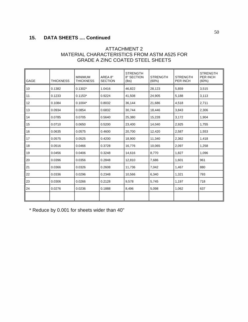
50 15. DATA SHEETS .... Continued
ATTACHMENT 2 MATERIAL CHARACTERISTICS FROM ASTM A525 FOR
GRADE A ZINC COATED STEEL SHEETS
GAGE THICKNESS MINIMUM THICKNESS
AREA 8" SECTION
STRENGTH 8" SECTION (lbs)
STRENGTH (60%)
STRENGTH PER INCH
STRENGTH PER INCH (60%)
10 0.1382 0.1302* 1.0416 46,822 28,123 5,859 3,515
11 0.1233 0.1153* 0.9224 41,508 24,905 5,188 3,113
12 0.1084 0.1004* 0.8032 36,144 21,686 4,518 2,711
13 0.0934 0.0854 0.6832 30,744 18,446 3,843 2,306
14 0.0785 0.0705 0.5640 25,380 15,228 3,172 1,904
15 0.0710 0.0650 0.5200 23,400 14,040 2,925 1,755
16 0.0635 0.0575 0.4600 20,700 12,420 2,587 1,553
17 0.0575 0.0525 0.4200 18,900 11,340 2,362 1,418
18 0.0516 0.0466 0.3728 16,776 10,065 2,097 1,258
19 0.0456 0.0406 0.3248 14,616 8,770 1,827 1,096
20 0.0396 0.0356 0.2848 12,810 7,686 1,601 961
21 0.0366 0.0326 0.2608 11,736 7,042 1,467 880
22 0.0336 0.0296 0.2348 10,566 6,340 1,321 793
23 0.0306 0.0266 0.2128 9,578 5,745 1,197 718
24 0.0276 0.0236 0.1888 8,496 5,098 1,062 637
* Reduce by 0.001 for sheets wider than 40"
______________________________________________________________________
______________________________________________________________________
______________________________________________________________________
______________________________________________________________________
______________________________________________________________________
______________________________________________________________________
______________________________________________________________________
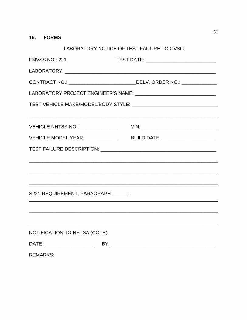
51 16. FORMS
LABORATORY NOTICE OF TEST FAILURE TO OVSC
FMVSS NO.: 221 TEST DATE: __________________________
LABORATORY: ________________________________________________________
CONTRACT NO.: _________________________DELV. ORDER NO.: _____________
LABORATORY PROJECT ENGINEER'S NAME: ______________________________
TEST VEHICLE MAKE/MODEL/BODY STYLE: ________________________________
VEHICLE NHTSA NO.: ______________ VIN: ____________________________
VEHICLE MODEL YEAR: ____________ BUILD DATE: ____________________
TEST FAILURE DESCRIPTION: ___________________________________________
S221 REQUIREMENT, PARAGRAPH ______:
NOTIFICATION TO NHTSA (COTR):
DATE: __________________ BY: _______________________________________
REMARKS:

52 16. FORMS....Continued
MONTHLY TEST STATUS REPORT
FMVSS 221
DATE OF REPORT: __________________
No.
SCHOOL BUS NHTSA No., MAKE & MODEL
COMPLIANCE TEST DATE
PASS/ FAIL
DATE REPORT SUBMITTED
DATE INVOICE SUBMITTED
INVOICE PAYMENT DATE
1
2
3
4
5
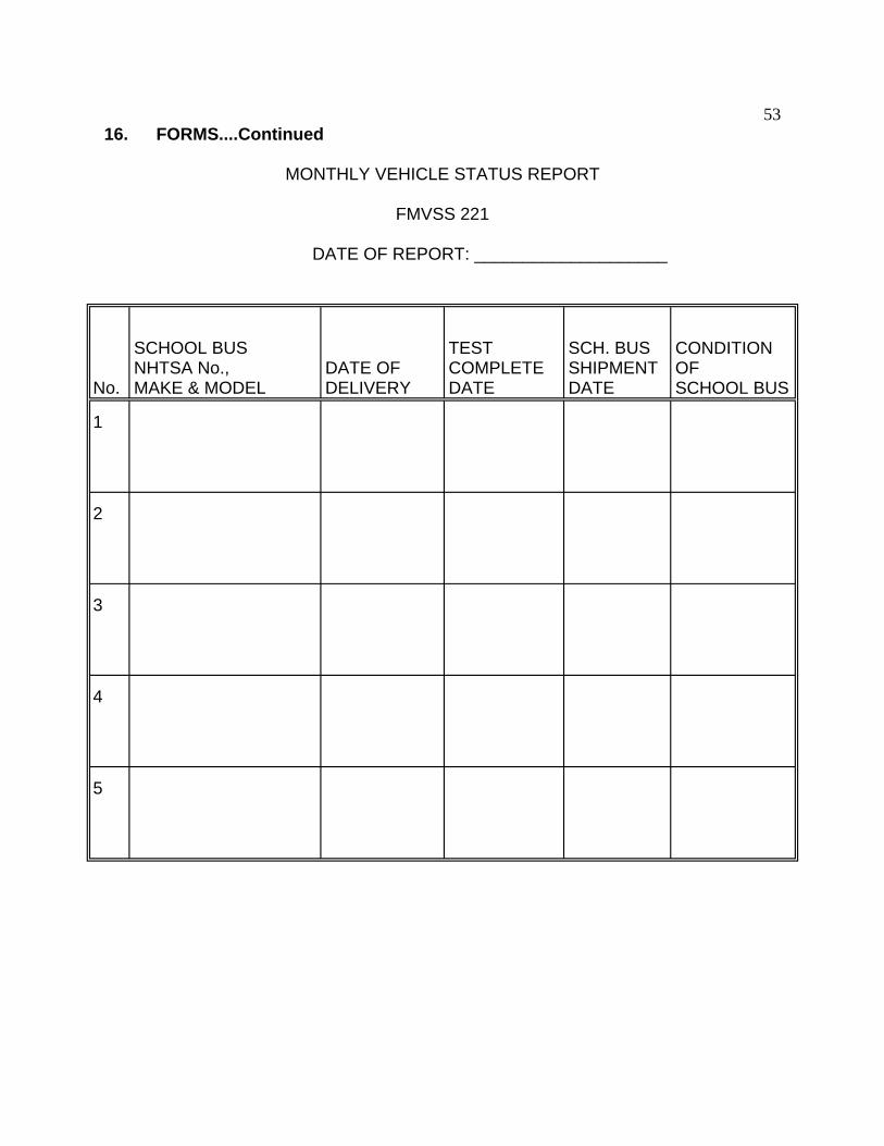
53 16. FORMS....Continued
MONTHLY VEHICLE STATUS REPORT
FMVSS 221
DATE OF REPORT: ____________________
No.
SCHOOL BUS NHTSA No., MAKE & MODEL
DATE OF DELIVERY
TEST COMPLETE DATE
SCH. BUS SHIPMENT DATE
CONDITION OF SCHOOL BUS
1
2
3
4
5

54
16. FORMS....Continued
VEHICLE CONDITION REPORT
CONTRACT NO.: DTNH22- DATE: ______________
FROM: _______________________________________________________________
TO: __________________________________________________________________
The following vehicle has been subjected to compliance testing for FMVSS No. _____
The vehicle was inspected upon arrival at the laboratory for the test and found to contain all of the equipment listed below. All variances have been reported within 2 working days of vehicle arrival, by letter, to the NHTSA Industrial Property Manager (NPO-220), with a copy to the OVSC COTR. The vehicle is again inspected, after the above test has been conducted, and all changes are noted below. The final condition of the vehicle is also noted in detail.
MODEL YEAR/MAKE/MODEL/BODY STYLE:
NHTSA NO.: BODY COLOR: VIN: ________________
ODOMETER READINGS: ARRIVAL - miles DATE - _________
COMPLETION - miles DATE - _________
PURCHASE PRICE: $ DEALER'S NAME: ___________________________
ENGINE DATA: Cylinders Liters Cubic Inches
TRANSMISSION DATA: Automatic Manual No. of Speeds
FINAL DRIVE DATA: Rear Drive Front Drive 4 Wheel Drive
TIRE DATA: Size - Mfr. - ______________________
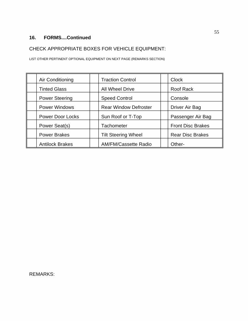
55 16. FORMS....Continued
CHECK APPROPRIATE BOXES FOR VEHICLE EQUIPMENT:
LIST OTHER PERTINENT OPTIONAL EQUIPMENT ON NEXT PAGE (REMARKS SECTION)
Air Conditioning Traction Control Clock
Tinted Glass All Wheel Drive Roof Rack
Power Steering Speed Control Console
Power Windows Rear Window Defroster Driver Air Bag
Power Door Locks Sun Roof or T-Top Passenger Air Bag
Power Seat(s) Tachometer Front Disc Brakes
Power Brakes Tilt Steering Wheel Rear Disc Brakes
Antilock Brakes AM/FM/Cassette Radio Other-
REMARKS:
56
16. FORMS....Continued
Equipment that is no longer on the test vehicle as noted on previous page:
Explanation for equipment removal:
School Bus Condition:
RECORDED BY: DATE: _______________
APPROVED BY: _____________________