Embed Size (px)
Citation preview

TP-202aS-01 January 21, 2011
U.S. DEPARTMENT OF TRANSPORTATION
NATIONAL HIGHWAY TRAFFIC SAFETY ADMINISTRATION
LABORATORY TEST PROCEDURE
FOR
FMVSS 202aS
Head Restraints - Dimensional and Static Testing
ENFORCEMENT Office of Vehicle Safety Compliance
Mail Code: NVS-220 1200 New Jersey Ave. SE Washington, DC 20590

TP-202aS-01 ii
REVISION CONTROL LOG FOR OVSC LABORATORY
TEST PROCEDURES
TP-202aS-01 Head Restraints
TEST PROCEDURE FMVSS 202aD
DESCRIPTION REV.
No.
DATE
AMENDMENT EFFECTIVE
DATE
00 12/22/04 69 FR 74848 3/14/05 Original release signed by O.D.
01 1/xx/2011 Final Rule 1/xx/2011 Updates for final rule petitions for reconsideration.
02
03
04
05
06
07
08
09
10
TP-202aS-01 iii
1. PURPOSE AND APPLICATION ............................................................................................................... 1 2. GENERAL REQUIREMENTS .................................................................................................................... 2 3. SECURITY .................................................................................................................................................... 4 4. GOOD HOUSEKEEPING ........................................................................................................................... 4 5. TEST SCHEDULING AND MONITORING .............................................................................................. 4 6. TEST DATA DISPOSITION ....................................................................................................................... 5 7. GOVERNMENT FURNISHED PROPERTY (GFP) ................................................................................ 6 8. CALIBRATION OF TEST INSTRUMENTS ............................................................................................. 7 9. DEFINITIONS ............................................................................................................................................... 9 10. TEST EQUIPMENT & FACILITY REQUIREMENTS ........................................................................ 10 11. PHOTOGRAPHIC DOCUMENTATION .............................................................................................. 11 12. PRETEST REQUIREMENTS ................................................................................................................ 13
12.1 DETAILED TEST AND QUALITY CONTROL PROCEDURES REQUIRED ......................... 14 12.2 TEST TEMPERATURE CONDITIONS ........................................................................................ 14
13. COMPLIANCE TEST EXECUTION ..................................................................................................... 14 14. POST TEST REQUIREMENTS ............................................................................................................ 15 15. REPORTS ................................................................................................................................................ 15
15.1 MONTHLY STATUS REPORTS...................................................................................................... 15 15.2 APPARENT NONCOMPLIANCE .................................................................................................. 15 15.3 FINAL TEST REPORTS ................................................................................................................. 15
15.3.1 COPIES ...................................................................................................................................... 15 15.3.2 REQUIREMENTS ..................................................................................................................... 16 15.3.3 FIRST THREE PAGES ............................................................................................................ 16 15.3.4 TABLE OF CONTENTS .......................................................................................................... 21
16. FORMS ..................................................................................................................................................... 22 Data Sheet 1....................................................................................................................................................... 24 Data Sheet 2....................................................................................................................................................... 36 Data Sheet 3....................................................................................................................................................... 37 Data Sheet 4....................................................................................................................................................... 39 Data Sheet 5....................................................................................................................................................... 42 Data Sheet 6....................................................................................................................................................... 43 Data Sheet 7....................................................................................................................................................... 46 Data Sheet 8....................................................................................................................................................... 48 Data Sheet 9....................................................................................................................................................... 51

TP-202aS-01 1
1. PURPOSE AND APPLICATION
This document is provided by the National Highway Traffic Safety Administration (NHTSA), Office of Vehicle Safety Compliance (OVSC) for the purpose of presenting procedures for uniform testing and providing suggestions for the use of specific equipment for contracted testing laboratories. It contains requirements based on the test procedures specified in the Federal Motor Vehicle Safety Standard(s) (FMVSS) and any applicable safety Regulations. The OVSC test procedures include requirements that are general in scope to provide flexibility for contracted laboratories to perform compliance testing and are not intended to limit or restrain a contractor from developing or utilizing any testing techniques or equipment which will assist in procuring the required compliance test data. These test procedures do not constitute an endorsement or recommendation for use of any particular product or testing method.
Prior to conducting compliance testing, contracted laboratories are required to submit a detailed test procedure to the Contracting Officer's Technical Representative (COTR) to demonstrate concurrence with the OVSC laboratory test procedure and the applicable FMVSS. If any contractor views any part of an OVSC laboratory test procedure to be in conflict with a FMVSS or observes deficiencies in a laboratory test procedure, the contractor is required to advise the COTR and resolve the discrepancy prior to the start of compliance testing or as soon as practicable. The contractor’s test procedure must include a step-by-step description of the methodology and detailed check-off sheets. Detailed check-off sheets shall also be provided for the testing instrumentation including a complete listing of the test equipment with make and model numbers. The list of test equipment shall include instrument accuracy and calibration dates. All equipment shall be calibrated in accordance with the manufacturer’s instructions. There shall be no contradictions between the laboratory test procedure and the contractor’s in-house test procedure. Written approval of the in-house test procedures shall be obtained from the COTR before initiating the compliance test program. NOTE: The OVSC Laboratory Test Procedures, prepared for the limited purpose of use by independent laboratories under contract to conduct compliance tests for the OVSC, are not rules, regulations or NHTSA interpretations regarding the meaning of a FMVSS. The laboratory test procedures are not intended to limit the requirements of the applicable FMVSS(s). In some cases, the OVSC laboratory test procedures do not include all of the various FMVSS minimum performance requirements. In addition, the laboratory test procedures may specify test conditions that are less severe than the minimum requirements of the standard. The laboratory test procedures may be modified by the OVSC at any time without notice, and the COTR may direct or authorize contractors to deviate from these procedures, as long as the tests are performed in a manner consistent with the standard itself and within the scope of the contract. Laboratory test procedures may not be relied upon to create any right or benefit in any person. Therefore, compliance of a vehicle or item of motor vehicle equipment is not necessarily guaranteed if the manufacturer limits its certification tests to those described in the OVSC laboratory test procedures.

TP-202aS-01 2
2. GENERAL REQUIREMENTS FMVSS 202a, Head Restraints, specifies requirements for head restraints to reduce the frequency and severity of neck injury in rear end and other collisions. The standard applies to each front and rear outboard Designated Seating Position (DSP) with a head restraint, and allows head restraints to be tested either dynamically or statically. Exceptions are made for school buses; refer to the Code of Federal Regulations for the specific exceptions. This test procedure covers the static requirements. The head restraint must meet the following requirements:
1. Height (S 4.2.1): a. Front outboard, minimum height 800 mm Roof line exception if 800 mm not achievable (not more than 50 mm vertical distance from
roofline in convertible and 25 mm for other vehicles), must have minimum height of 700 mm in lowest position of adjustment.
b. All outboard, minimum height of 750 mm Roof line exception if 800 mm not achievable (not more than 50 mm vertical distance from
roofline in convertible and 25 mm for other vehicles) 2. Width (S 4.2.2): When measured 65 + 3 mm below the top of the head restraint, must be not
less than 170 mm, except the lateral width of the head restraint for front outboard designated seating positions in a vehicle with a front center designated seating position, must be not less than 254 mm.
3. Front Outboard DSP Backset (S 4.2.3): 55 mm maximum backset 4. Gaps within the head restraint and between the head restraint and seat using a 165 mm
sphere (S 4.2.4.1): 60 mm maximum gap 5. Gaps between the adjustable head restraint and seat using a 25 mm cylinder (S 4.2.4.2): 25
mm maximum gap 6. Energy absorption (S 4.2.5): 785 m/s2 maximum deceleration for more than 3 milliseconds
when impacted at any velocity up to and including 24.1 km/h 7. Height Retention (S 4.2.6)
a. When an initial 50 + 1 N reference load is applied to the head restraint, the displacement shall be no more than 25 mm.
b. Apply an additional 450 N load (500 N total) to the head restraint. Reduce the load to the 50 + 1 N reference load. The head restraint must return to within 13 mm of the reference point.
8. Backset retention (S 4.2.7. a) a. When a 37 + 0.7 Nm reference moment is applied to the head restraint, the
displacement shall be no more than 25 mm. b. When a 373 + 7.5 Nm moment is applied to the head restraint, the displacement shall
be no more than 102 mm. c. When reduced from the 373 + 7.5 Nm moment to the 37 + 0.7 Nm initial reference
moment, the head restraint must return to within13 mm of the initial reference position. 9. Strength (S 4.2.7.b): Support 890 N for 5 seconds 10. Folding or Retracting Rear Head Restraints Non-Use Positions. (S 4.4) 11. Removability of Head Restraints. (S 4.5)

TP-202aS-01 3
METRIC SYSTEM OF MEASUREMENT
Section 5164 of the Omnibus Trade and Competitiveness Act (Pub. L. 100-418) establishes that the metric system of measurement is the preferred system of weights and measures for trade and commerce in the United States. Executive order 12770 directs Federal agencies to comply with the Act by converting regulatory standards to the metric system after September 30, 1992. In a final rule published on March 15, 1990 (60 FR 13639), NHTSA completed the first phase of metrication, converting English measurements in several regulatory standards to the metric system. Since then, metrication has been applied to other regulatory standards (63 FR 28912).
Accordingly, the OVSC laboratory test procedures include revisions to comply with governmental directives in using the metric system. Regulatory standards converted to metric units are required to use metric measurements in the test procedures, whereas standards using English units are allowed to use English measurements or to use English measurements in combination with metric equivalents in parentheses. All final compliance test reports are required to include metric measurements for standards using metrication.
NOTE: The methodology for rounding measurement in the test reports shall be made in accordance with ASTM E29-06b, “Standard Practice for Using Significant Digits in Test Data to Determine Conformance with Specifications.”

TP-202aS-01 4
3. SECURITY
The contractor shall provide appropriate security measures to protect the OVSC test vehicles and Government Furnished Property (GFP) from unauthorized personnel during the entire compliance testing program. The contractor is financially responsible for any acts of theft and/or vandalism which occur during the storage of test vehicles and GFP. Any security problems which arise shall be reported by telephone to the Industrial Property Manager (IPM), Office of Acquisition Management, within two working days after the incident. A letter containing specific details of the security problem shall be sent to the IPM (with copy to the COTR) within 48 hours.
The contractor shall protect and segregate the data that evolves from compliance testing before and after each vehicle test. No information concerning the vehicle safety compliance testing program shall be released to anyone except the COTR, unless specifically authorized by the COTR or the COTR's Division Chief.
NOTE: No individuals, other than contractor personnel directly involved in the compliance testing program or OVSC personnel, shall be allowed to witness any vehicle or equipment item compliance test or test dummy calibration unless specifically authorized by the COTR.
4. GOOD HOUSEKEEPING
Contractors shall maintain the entire vehicle compliance testing area, fixtures and instrumentation in a neat, clean and painted condition with test instruments arranged in an orderly manner consistent with good test laboratory housekeeping practices.
5. TEST SCHEDULING AND MONITORING
The contractor shall submit a test schedule to the COTR prior to conducting the first compliance test. Tests shall be completed at intervals as required in the contract. If not specified, the first test shall be conducted within 6 weeks after receiving the first delivered unit. Subsequent tests shall be completed in no longer that 1 week intervals unless otherwise specified by the COTR.
Scheduling of tests shall be adjusted to permit vehicles (or equipment, whichever applies) to be tested to other FMVSSs as may be required by the OVSC. All compliance testing shall be coordinated with the COTR in order to allow monitoring by the COTR and/or other OVSC personnel if desired. The contractor shall submit a monthly test status report and a vehicle status report (if applicable) to the COTR. The vehicle status report shall be submitted until all vehicles are disposed of. The status report forms are provided in the forms section.

TP-202aS-01 5
6. TEST DATA DISPOSITION
The Contractor shall make all preliminary compliance test data available to the COTR on location within 30 minutes after the test (or within four hours for equipment testing). Final test data, including digital printouts and computer generated plots (if applicable), shall be available to the COTR in accordance with the contract schedule or if not specified within two working days. Additionally, the Contractor shall analyze the preliminary test results as directed by the COTR.
All backup data sheets, strip charts, recordings, plots, technicians’ notes, etc., shall be either sent to the COTR or destroyed at the conclusion of each delivery order, purchase order, etc. ((For equipment testing) The test data shall be retained by the contractor for a minimum of 3 years after conclusion of each delivery order, purchase order, etc. The COTR shall direct final disposition at that time.)
The contractor shall protect and segregate the data that evolves from compliance testing before and after each test.
A. INVALID TEST DESCRIPTION
An invalid compliance test is one, which does not conform precisely to all requirements/specifications of the OVSC Laboratory Test Procedure and Statement of Work applicable to the test.
B. INVALID TEST NOTIFICATION
The Contractor shall notify NHTSA of any test not meeting all requirements/specifications of the OVSC Laboratory Test Procedure and Statement of Work applicable to the test, by telephone, within 24 hours of the test and send written notice to the COTR within 48 hours or the test completion.
C. RETEST NOTIFICATION
The Contracting Officer of NHTSA is the only NHTSA official authorized to notify the Contractor that a retest is required. The retest shall be completed within 2 weeks after receipt of notification by the Contracting Officer that a retest is required.
D. WAIVER OF RETEST
NHTSA, in its sole discretion, reserves the right to waive the retest requirement. This provision shall not constitute a basis for dispute over the NHTSA's waiving or not waiving any requirement.

TP-202aS-01 6
E. TEST VEHICLE
NHTSA shall furnish only one vehicle for each test ordered. The Contractor shall furnish the test vehicle required for the retest. The retest vehicle shall be equipped as the original vehicle. The original vehicle used in the invalid test shall remain the property of NHTSA, and the retest vehicle shall remain the property of the Contractor. The Contractor shall retain the retest vehicle for a period not exceeding 180 days if it fails the test. If the retest vehicle passes the test, the Contractor may dispose of it upon notification from the COTR that the test report has been accepted.
F. TEST REPORT
No test report is required for any test that is determined to be invalid unless NHTSA specifically decides, in writing, to require the Contractor to submit such report. The test data from the invalid test must be safeguarded until the data from the retest has been accepted by the COTR. The report and other required deliverables for the retest vehicle are required to be submitted to the COTR within 3 weeks after completion of the retest.
G. DEFAULT
The Contractor is subject to the default and subsequent re-procurement costs for non-delivery of valid or conforming tests (pursuant to the Termination For Default clause in the contract).
H. NHTSA'S RIGHTS
None of the requirements herein stated shall diminish or modify the rights of NHTSA to determine that any test submitted by the Contractor does not conform precisely to all requirements/specifications of the OVSC Laboratory Test Procedure and Statement of Work applicable to the test.
7. GOVERNMENT FURNISHED PROPERTY (GFP)
GFP consist of test vehicles and test equipment. The GFP is authorized by contractual agreement. The contractor is responsible for the following. A. ACCEPTANCE OF TEST VEHICLES The contractor has the responsibility of accepting each GFP test vehicle whether delivered by a new vehicle dealership or another vehicle transporter. In both instances, the Contractor acts on behalf of the OVSC when signing an acceptance of the GFP test vehicle delivery order. When a GFP vehicle is delivered, the contractor must verify:
1. All options listed on the "window sticker" are present on the test vehicle. 2. Tires and wheel rims are new and the same as listed. 3. There are no dents or other interior or exterior flaws in the vehicle body. 4. The vehicle has been properly prepared and is in running condition.

TP-202aS-01 7
5. The glove box contains an owner's manual, warranty document, consumer information, and extra set of keys.
6. Proper fuel filler cap is supplied on the test vehicle. 7. Spare tire, jack, lug wrench and tool kit (if applicable) is located in the vehicle cargo
area. 8. The VIN (vehicle identification number) on the vehicle condition report matches the VIN
on the vehicle. 9. The vehicle is equipped as specified by the COTR.
A Vehicle Condition form will be supplied to the Contractor by the COTR when the test vehicle is transferred from a new vehicle dealership or between test contracts. The upper half of the form is used to describe the vehicle as initially accepted. The lower half of the Vehicle Condition form provides space for a detailed description of the post-test condition. The contractor must complete a Vehicle Condition form for each vehicle and deliver it to the COTR with the Final Test Report or the report will NOT be accepted for payment. If the test vehicle is delivered by a government contracted transporter, the contractor should check for damage which may have occurred during transit. GFP vehicle(s) shall not be driven by the contractor on public roadways unless authorized by the COTR.
B. NOTIFICATION OF COTR The COTR must be notified within 24 hours after a vehicle (and/or equipment item) has been delivered. In addition, if any discrepancy or damage is found at the time of delivery, a copy of the Vehicle Condition form shall be sent to the COTR immediately.
8. CALIBRATION OF TEST INSTRUMENTS
Before the Contractor initiates the vehicle safety compliance test program, a test instrumentation calibration system must be implemented and maintained in accordance with established calibration practices. The calibration system shall include the following as a minimum:
A. Standards for calibrating the measuring and test equipment shall be stored and used
under appropriate environmental conditions to assure their accuracy and stability.
B All measuring instruments and standards shall be calibrated by the Contractor, or a commercial facility, against a higher order standard at periodic intervals not exceeding12 months for instruments and 12 months for the calibration standards except for static types of measuring devices such as rulers, weights, etc., which shall be calibrated at periodic intervals not to exceed two years. Records, showing the calibration traceability to the National Institute of Standards and Technology (NIST), shall be maintained for all measuring and test equipment.

TP-202aS-01 8
Accelerometers shall be calibrated every twelve months or after a test failure or after any indication from calibration checks that there may be a problem with the accelerometer whichever occurs sooner.
C. All measuring and test equipment and measuring standards shall be labeled with the
following information:
1. Date of calibration
2. Date of next scheduled calibration
3. Name of the technician who calibrated the equipment
D. A written calibration procedure shall be provided by the Contractor, which includes as a minimum the following information for all measurement and test equipment:
1. Type of equipment, manufacturer, model number, etc.
2. Measurement range
3. Accuracy
4. Calibration interval
5. Type of standard used to calibrate the equipment (calibration traceability of the
standard must be evident).
6. The actual procedures and forms used to perform the calibrations.
E. Records of calibration for all test instrumentation shall be kept by the Contractor in a manner that assures the maintenance of established calibration schedules.
F. All such records shall be readily available for inspection when requested by the COTR.
The calibration system shall need the acceptance of the COTR before vehicle safety compliance testing commences.
G. Test equipment shall receive a system functional check out using a known test input
immediately before and after the test. This check shall be recorded by the test technician(s) and submitted with the final report.
H. Anthropomorphic test devices shall be calibrated before and the calibration checked
after each crash and low risk deployment test. The calibrations and calibration check shall be submitted with the final report.
I. The Contractor may be directed by NHTSA to evaluate its data acquisition system.
Further guidance is provided in the International Standard ISO 10012-1, “Quality Assurance Requirements for Measuring Equipment” and American National Standard ANSI/NCSL Z540-1, “Calibration Laboratories and Measuring and Test Equipment General Requirements.”

TP-202aS-01 9
NOTE: In the event of a failure to meet the standard' s minimum performance requirements addit ional calibrat ion checks of some crit ically sensit ive test equipment and instrumentat ion may be required for verif icat ion of accuracy. The necessity for the calibrat ion w ill be at the COTR's discret ion and shall be performed w ithout addit ional cost.
9. DEFINITIONS
9.1 BACKSET The minimum horizontal distance between the rear of a representation of the head of a seated 50th percentile male occupant and the head restraint, as measured by the head restraint measurement device. (S3)
9.2 DESIGNATED SEATING POSITION (DSP) Designated seating position means a seat location that has a seating surface width, as described in §571.10(c) of this part, of at least 330 mm (13 inches). The number of designated seating positions at a seat location is determined according to the procedure set forth in § 571.10(b) of this part. However, for trucks and multipurpose passenger vehicles with a gross vehicle weight rating greater than 10,000 lbs, police vehicles as defined in S7 of FMVSS No. 208, firefighting vehicles, ambulances, and motor homes, a seating location that is labeled in accordance with S4.4 of FMVSS No. 207 will not be considered a designated seating position. For the sole purpose of determining the classification of any vehicle sold or introduced into interstate commerce for purposes that include carrying students to and from school or related events, any location in such a vehicle intended for securement of an occupied wheelchair during vehicle operation is regarded as four designated seating positions. (571.3)
9.3 HEAD RESTRAINT
A device that limits rearward displacement of a seated occupant's head relative to the occupant’s torso. (S3)
9.4 HEAD RESTRAINT MEASUREMENT DEVICE (HRMD) The Society of Automotive Engineers (SAE) (July 1995) J826 three-dimensional manikin with a head form attached, representing the head position of a seated 50th percentile male, with sliding scale at the back of the head for the purpose of measuring backset. (S3)
9.5 HEIGHT When used in reference to a head restraint, the distance from the H-point measured parallel to the torso reference line defined by the three dimensional SAE J826 (July 1995) manikin, to a plane normal to the torso reference line. (S3)
9.6 H-POINT
Means the pivot center of the torso and thigh on the three-dimensional device used in defining and measuring vehicle seating accommodation, as defined in Society of Automotive Engineers (SAE) Recommended Practice J1100, revised February 2001"Motor Vehicle Dimensions" (incorporated by reference, see § 571.5). (§ 571.3)

TP-202aS-01 10
9.7 INTENDED FOR OCCUPANT USE When used in reference to the adjustment of a seat, positions other than that intended solely for the purpose of allowing ease of ingress and egress of occupants and access to cargo storage areas of a vehicle. (S3)
9.8 OUTBOARD DESIGNATED SEATING POSITION
A designated seating position where a longitudinal vertical plane tangent to the outboard side of the seat cushion is less than 12 inches from the innermost point on the inside surface of the vehicle at a height between the design H-point and the shoulder reference point (as shown in fig. 1 of Federal Motor Vehicle Safety Standard No. 210) and longitudinally between the front and rear edges of the seat cushion. (571.3)
9.9 REAR HEAD RESTRAINT
A rear seat back or any independently adjustable seat component attached to or adjacent to a seat back that has a height equal to or greater than 700 mm in any position of adjustment. (S3)
9.10 TOP OF THE HEAD RESTRAINT The point on the head restraint with the greatest height. (S3)
9.11 TORSO LINE The line connecting the “H” point and the shoulder reference point as defined in Society of Automotive Engineers (SAE) Standard J787b, revised September 1966, “Motor Vehicle Seat Belt Anchorage” (incorporated by reference, see §571.5). (571.3)
10. TEST EQUIPMENT & FACILITY REQUIREMENTS
DIMENSIONAL MEASUREMENT TOOLS
A. Three-dimensional H-point manikin, SAE J826, July 1995. B. 25 mm ± 0.25 mm diameter sphere
C. Steel Tape
D. Carpenter’s Square
E. Calipers with accuracy of ± 0.75 mm and sufficient range for measuring the width of the
head restraint.
F. Spherical head form with a 165 ± 2 mm diameter with surface roughness less than 1.6 μm, root mean square. (The head form is designed by and available from the ICBC, 151 West Esplanade, North Vancouver, BC V7M 3H9, Canada ( www.icbc.com ).)
VEHICLE PREPARATION BUILDING

TP-202aS-01 11
The Contractor shall have a temperature controlled building large enough to house and prepare the test vehicle for sled testing, and allow for government, vehicle manufacturer, and laboratory personnel to move around the test vehicle. The building climate control must be capable of maintaining the ambient air temperature between 20.5°C and 22.2°C. TEST DATA ACQUISITION AND REDUCTION A precision time system compatible with the test equipment shall be used to provide a time reference for all recorded data (see Figure 1). A system that identifies the precise instant of sled test actuation will be incorporated with the time reference signal. Data shall be collected for at least 300 ms after time zero, pre-filtered (Class 1000) and digitized at a minimum rate of 10,000 samples per second.
TEST VEHICLEONBOARD
INSTRUMENTATION
PART 572DUMMY DATA
CHANNELS
FM TAPESTORAGE
DIGITALSAE
FILTERS
FM ANALOGTAPE
RECORDERS
DIGITALDISK
STORAGE
GRAPHICSCOPYINGMACHINE
DIGITALCOMPUTER
UMBILICALCABLE
ANALOG SIGNALCONDITIONING
FILTERS
TYPICAL VEHICLE AND OCCUPANT TESTDATA ACQUISITION SYSTEM
Figure 1
11. PHOTOGRAPHIC DOCUMENTATION
The contractor shall take digital photographs of the test execution procedures. Photographs shall be taken in color and contain clear images. A tag, label or placard identifying the test item, NHTSA number (if applicable) and date shall appear in each photograph and must be legible. Each photograph shall be labeled as to the subject matter. The required resolution for digital photographs is a minimum of 1,600 x 1,200 pixels. Digital photographs are required to be created in color and in a JPG format. Glare or light from any illuminated or reflective surface shall be minimized while taking photographs.

TP-202aS-01 12
The test reports shall include enough photographs to describe the testing in detail and shall be organized in a logical succession of consecutive pictures. The digital photographs shall be included in the test report as 203 mm x 254 mm or 215.9 mm x 279 mm (8 x 10 or 8½ x 11 inch) pictures (or for equipment testing -- 125 mm x 175 mm (5 x 7 inch) pictures). All photographs are required to be included in the test report in the event of a test failure. Any failure must be photographed at various angles to assure complete coverage. Upon request, the photographs shall be sent to the COTR on a CD or DVD and saved in a “read only” format to ensure that the digital photographs are the exact pictures taken during testing and have not been altered from the original condition. PHOTOGRAPHIC VIEWS As a minimum the following test photographs shall be included in each vehicle final test report, submitted by the contractor: A. Left side view of vehicle B. Right side view of vehicle C. 3/4 frontal view from left side of vehicle D. 3/4 rear view from right side of vehicle E. Vehicle's certification label F. Vehicle's tire information label G. 3/4 frontal view of each head restraint system E. J826 manikin positioned, as required by the standard, in each DSP F. Measurement of head restraint width G. Removal of front head restraint with a tool (if applicable) H. Reinstallation of the front head restraint (if applicable) I. Action necessary for rear head restraint adjustment (if applicable) J. Action necessary for rear head restraint removal (if applicable) K. Reinstallation of the rear head restraint (if applicable) L. For head restraints with a manual non-use position: (if applicable)
a. Side view of head restraint in a position of occupant use showing the reference line and the initial inclination of the line
b. Side view of head restraint in a non-use position showing the reference line and
the inclination of the line
TP-202aS-01 13
M. For head restraints with an automatic non-use position: (if applicable)
a. Side view of head restraint in a non-use position
b. Side view of head restraint in a position of occupant use with the 5th percentile female Hybrid III Subpart O dummy positioned in the seat
INFORMATIONAL PLACARDS
Vehicle identification placards shall be positioned so that at least 1 placard will be visible in the field-of-view for each of the cameras. The following information will be shown:
A. Vehicle's NHTSA Number
B. “FMVSS 202a Static Test”
C. Date of test
D. Name of contract laboratory
E. Vehicle year, make and model
12. PRETEST REQUIREMENTS
RECEIVING-INSPECTION OF TEST VEHICLE Complete the "Vehicle Condition" form supplied by the COTR.
Upon receipt of the test vehicle, it shall be identified with a visible sign or placard showing the following information:
A. Vehicle Make/Model
B. Vehicle Identification Number (VIN)
C. Vehicle NHTSA number (provided by COTR)
D. Compliance Test for Head Restraints (S202a).
Before taking each required test photo, place the sign or placard noted above in the field of view. The sign size and location should not obstruct the test detail being highlighted in the photograph.
The head restraint system, seat, all associated components and trim shall be inspected for function and damage. Record the results of this examination on the appropriate data sheet. If structural damage or other defects are noted that could influence the test results obtain approval from the COTR before initiating the test program.

TP-202aS-01 14
12.1 DETAILED TEST AND QUALITY CONTROL PROCEDURES REQUIRED Prior to conducting any compliance test, contractors shall:
A. Verify COTR approval of Contractor’s in-house test procedure, B. Verify the training of technicians for performance of this test, C. Verify the calibration status of test equipment, D. Review applicable revision of FMVSS 202a, E. Review vehicle Owner’s Manual (or equipment mfg. instructions), F. Set cold tire pressures according to the vehicle manufacturer’s recommendations, and G. Submit a detailed in-house compliance test procedure to the COTR that includes:
a. A step-by-step description of the methodology to be used. b. A written Quality Control (QC) Procedure that shall include calibrations, the data review
process, report review, and the people assigned to perform on each task. c. A complete listing of test equipment that shall include instrument accuracy and
calibration dates. d. Detailed check-off lists to be used during the test and during the data review. These
lists shall include all test procedure requirements and FMVSS requirements pertaining to the safety standard for which testing is being performed. Each separate check-off sheet shall identify the lab, test date, vehicle and test technicians. These check sheets shall be used to document that all requirements and procedures have been complied with. These sheets shall be submitted with the test report.
There shall be no contradiction between the OVSC laboratory Test Procedure and the contractor’s in-house test procedure. The procedures shall cover all aspects of testing from vehicle receipt to submission of the final test report. Written approval of the procedures shall be obtained from the COTR before initiating the compliance test program. After testing commences, written approval shall also be obtained from the COTR prior to any changes in the procedures.
12.2 TEST TEMPERATURE CONDITIONS
Prior to conducting any measurements, the test vehicle must be soaked in an ambient air environment in the temperature range of 19°C to 26°C for a minimum of 4 hours. The Contractor shall mark the ambient air temperature recording with the date, time and technician name at the beginning of the 4 hour soak. Any excursions from the specified temperature must be noted on the recording along with the reason for the excursion. Temperature recordings shall be supplied to the COTR with final test reports.
13. COMPLIANCE TEST EXECUTION
1. Measure Height (S 4.2.1). Follow the steps outlined in Data Sheet 1 to determine the height of
the head restraint. a. Perform front outboard height measurements b. Perform all other outboard height measurements
2. Measure Width (S 4.2.2). Follow the steps outlined in Data Sheet 2 to determine the head restraint width.

TP-202aS-01 15
3. Measure Front Outboard DSP Backset (S 4.2.3). Follow the steps outlined in Data Sheet 3 to determine the backset of the head restraint.
4. Measure gaps within the head restraint and between the head restraint and seat using a 165 mm sphere (S 4.2.4.1). Follow the steps outlined in Data Sheet 4 to measure gaps within the head restraint.
5. Measure gaps between the adjustable head restraint and seat using a 25 mm cylinder (S 4.2.4.2). Follow the steps outlined in Data Sheet 5 to measure gaps between the head restraint and the seatback.
6. Measure Energy Absorption (S 4.2.5). Follow the steps outlined in Data Sheet 6 to measure energy absorption.
7. Measure Height Retention (S 4.2.6). Follow the steps outlined in Data Sheet 7 to measure height retention.
8. Measure Backset Retention (S 4.2.7. a). Follow the steps outlined in Data Sheet 8 to measure backset retention.
9. Measure Strength (S 4.2.7.b). Follow the steps outlined in Data Sheet 8 to measure strength. 10. Folding or Retracting Rear Head Restraints Non-Use Positions. (S 4.4). Follow the steps
outlined in Data Sheet 9 to determine if Folding and Retracting requirements are met. 11. Removability of Head Restraints. (S 4.5). Follow the steps outlined in Data Sheet 9 to
determine if Removability requirements are met. 14. POST TEST REQUIREMENTS
A. Verify all instrumentation, data sheets and photographs are complete. B. Copy applicable pages of the vehicle Owner’s Manual for attachment to the final test report C. Place all original records in a secure and organized file awaiting test data disposition.
15. REPORTS
15.1 MONTHLY STATUS REPORTS
The contractor shall submit a monthly Test Status Report and a Vehicle Status Report to the COTR. The Vehicle Status report shall be submitted until all vehicles are disposed of. Samples of the required reports are found in the report forms section.
15.2 APPARENT NONCOMPLIANCE
Any indication of a test failure shall be communicated by telephone to the COTR within 24 hours with written notification mailed within 48 hours (Saturdays and Sundays excluded). A Notice of Test Failure (see report forms section) with a copy of the particular compliance test data sheet(s) and preliminary data plot(s) shall be included. In the event of a test failure, a post test calibration check of some critically sensitive test equipment and instrumentation may be required for verification of accuracy. The necessity for the calibration shall be at the COTR's discretion and shall be performed without additional costs to the OVSC.
15.3 FINAL TEST REPORTS 15.3.1 COPIES

TP-202aS-01 16
In the case of an apparent test failure, three electronic copies on compact discs in both Word and PDF formats of the Final Test Report shall be submitted to the COTR for acceptance within three weeks of test completion. The Final Test Report format to be used by all contractors can be found in the "Report Section". Where there has been no indication of an apparent noncompliance, two electronic copies on compact discs in both Word and PDF formats of each Final Test Report shall be submitted to the COTR for acceptance within three weeks of test completion. No payment of contractor's invoices for conducting compliance tests will be made prior to the Final Test Report acceptance by the COTR. Contractors are requested to NOT submit invoices before the COTR is provided with copies of the Final Test Report.
Contractors are required to submit the first Final Test Report in draft form within one week after the compliance test is conducted. The contractor and the COTR will then be able to discuss the details of both test conduct and report content early in the compliance test program. Contractors are required to PROOF READ all Final Test Reports before submittal to the COTR. The OVSC will not act as a report quality control office for contractors. Reports containing a significant number of errors will be returned to the contractor for correction, and a "hold" will be placed on invoice payment for the particular test.
15.3.2 REQUIREMENTS
The Final Test Report and associated documentation (including photographs) are relied upon as the chronicle of the compliance test. The Final Test Report will be released to the public domain after review and acceptance by the COTR. For these reasons, each final report must be a complete document capable of standing by itself. The contractor should use DETAILED descriptions of all compliance test events. Any events that are not directly associated with the standard but are of technical interest should also be included. The contractor should include as much DETAIL as possible in the report. Instructions for the preparation of the first three pages of the final test report are provided for standardization.
15.3.3 FIRST THREE PAGES
A. FRONT COVER
A heavy paperback cover (or transparency) shall be provided for the protection of the final report. The information required on the cover is as follows:
(1) Final Report Number such as XXX-ABC-XX-001, where –
126 is the FMVSS tested ABC are the initials for the laboratory XX is the last two numbers of the Fiscal Year of the test program 001 is the Group Number (001 for the 1st test,
002 for the 2nd test, etc.)

TP-202aS-01 17
(2) Final Report Title and Subtitle such as SAFETY COMPLIANCE TESTING FOR FMVSS 202aD Head Restraints * * * * * * * * * * * * * * * * ABC Motor Company 20XX Saferider 4-door sedan NHTSA No. CX0401
(3) Contractor's Name and Address such as
COMPLIANCE TESTING LABORATORIES, INC. 4335 West Dearborn Street Detroit, Michigan 48090-1234
NOTE: DOT SYMBOL SHALL BE PLACED BETWEEN ITEMS (3) AND (4)
(4) Date of Final Report completion (5) The words "FINAL REPORT"
(6) The sponsoring agency's name and address as follows
U. S. DEPARTMENT OF TRANSPORTATION National Highway Traffic Safety Administration Enforcement Office of Vehicle Safety Compliance Mail Code: NVS-220, W43-481 1200 New Jersey Avenue, SE Washington, DC 20590
B. FIRST PAGE AFTER FRONT COVER When a contract test laboratory is reporting, a disclaimer statement and an acceptance signature block for the COTR shall be provided as follows:

TP-202aS-01 18
This publication is distributed by the National Highway Traffic Safety Administration in the interest of information exchange. Opinions, findings and conclusions expressed in this publication are those of the author(s) and not necessarily those of the Department of Transportation or the National Highway Traffic Safety Administration. The United States Government assumes no liability for its contents or use thereof. If trade or manufacturers' names or products are mentioned, it is only because they are considered essential to the object of the publication and should not be construed as an endorsement.
Prepared By: ______________________________
Approved By: ______________________________*
Approval Date: _____________________________*
FINAL REPORT ACCEPTANCE BY OVSC:*
Accepted By: ______________________________
Acceptance Date: ___________________________
* These lines not required when OVSC staff writes the Test Report
C. SECOND PAGE AFTER FRONT COVER
A completed Technical Report Documentation Page (Form DOT F1700.7) shall be completed for those items that are applicable with the other spaces left blank. Sample data for the applicable block numbers of the title page follows.
Block 1 — REPORT NUMBER
XXX-ABC-XX-001
Block 2 — GOVERNMENT ACCESSION NUMBER
Leave blank
Block 3 — RECIPIENT'S CATALOG NUMBER
Leave blank

TP-202aS-01 19
Block 4 — TITLE AND SUBTITLE
Final Report of FMVSS XXX Compliance Testing of 20XX Saferider 4-door sedan, NHTSA No. CX0401
Block 5 — REPORT DATE
Month Day, 20XX
Block 6 — PERFORMING ORGANIZATION CODE
ABC
Block 7 — AUTHOR(S)
John Smith, Project Manager Bill Doe, Project Engineer
Block 8 — PERFORMING ORGANIZATION REPORT NUMBER
ABC-DOT-XXX-00
Block 9 — PERFORMING ORGANIZATION NAME AND ADDRESS
ABC Laboratories 405 Main Street Detroit, MI 48070-1234
Block 10 — WORK UNIT NUMBER
Leave blank
Block 11 — CONTRACT OR GRANT NUMBER
DTNH22-XX-D-12345
Block 12 — SPONSORING AGENCY NAME AND ADDRESS
United States Department of Transportation National Highway Traffic Safety Administration Office of Vehicle Safety Compliance Mail Code: NVS-220 1200 New Jersey Avenue, SE Washington, DC 20590
Block 13 — TYPE OF REPORT AND PERIOD COVERED
Final Test Report Month Day to Month Day, 20XX

TP-202aS-01 20
Block 14 — SPONSORING AGENCY CODE
NVS-220
Block 15 — SUPPLEMENTARY NOTES
Leave blank
Block 16 — ABSTRACT
Compliance tests were conducted on the subject 200X Saferider 4-door sedan in accordance with the specifications of the Office of Vehicle Safety Compliance Test Procedure No. TP-XXX-0X for the determination of FMVSS XXX compliance. Test failures identified were as follows:
None
NOTE: Above wording must be shown with appropriate changes made for a particular compliance test. Any questions should be resolved with the COTR.
Block 17 — KEY WORDS
Compliance Testing Safety Engineering FMVSS XXX
Block 18 — DISTRIBUTION STATEMENT
Copies of this report are available from —
National Highway Traffic Safety Administration Technical Information Services Division, NPO-411 1200 New Jersey Avenue SE (Room E12-100) Washington DC 20590
e-mail: [email protected] FAX: 202-493-2833
Block 19 — SECURITY CLASSIFICATION OF REPORT
Unclassified
Block 20 — SECURITY CLASSIFICATION OF PAGE
Unclassified
Block 21 — NUMBER OF PAGES
Add appropriate number

TP-202aS-01 21
Block 22 — PRICE
Leave blank 15.3.4 TABLE OF CONTENTS
Final test report Table of Contents shall include the following:
Section 1 — Purpose of Compliance Test
Section 2 — Test Procedure and Discussion of Results
Section 3 — Test Data
Section 4 — Test Equipment List and Calibration Information
Section 5 — Photographs Section 6 — Other Documentation
Section 7 — Notice of Test Failure (if applicable)
TP-202aS-01 22
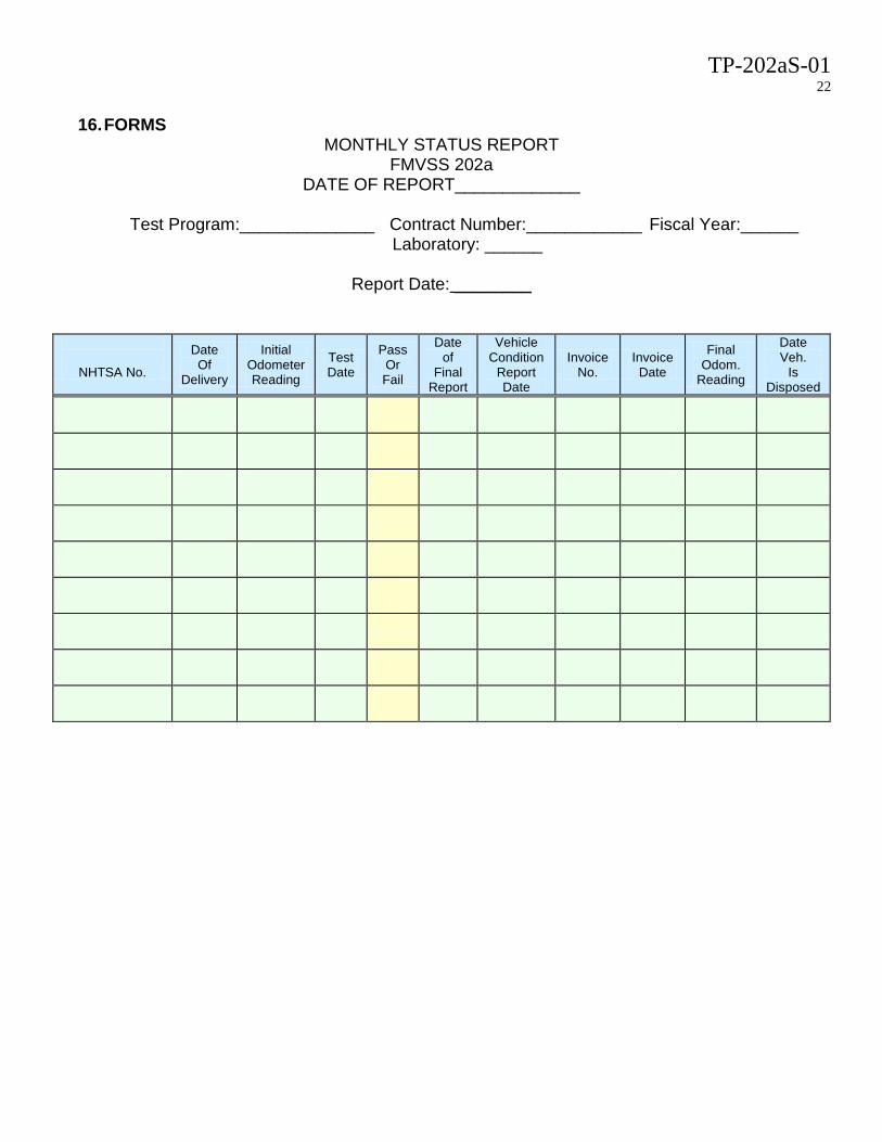
16. FORMS
MONTHLY STATUS REPORT FMVSS 202a
DATE OF REPORT_____________
Test Program:______________ Contract Number:____________ Fiscal Year:______ Laboratory: ______
Report Date: ________
NHTSA No.
Date Of
Delivery
Initial Odometer Reading
Test Date
Pass Or Fail
Date of
Final Report
Vehicle Condition
Report Date
Invoice No.
Invoice Date
Final Odom.
Reading
Date Veh.
Is Disposed

TP-202aS-01 23
LABORATORY NOTICE OF APPARENT TEST FAILURE TO OVSC
FMVSS NO. 202aS TEST DATE: _____________________________________________ LABORATORY: ___________________________________________________________ CONTRACT NO.: __________________________ DELIV. ORDER NO.: _____________ LABORATORY PROJECT ENGINEER'S NAME: _________________________________ TEST SPECIMEN DESCRIPTION: ____________________________________________ ________________________________________________________________________ VEHICLE NHTSA NO.: VIN: ____________________________________ MFR: ___________________________________________________________________ APPARENT TEST FAILURE DESCRIPTION: ___________________________________ ________________________________________________________________________ ________________________________________________________________________ ________________________________________________________________________ ________________________________________________________________________ FMVSS REQUIREMENT, PARAGRAPH S : ________________________________________________________________________ ________________________________________________________________________ ________________________________________________________________________ ________________________________________________________________________ NOTIFICATION TO NHTSA (COTR): __________________________________________ DATE: _______________ BY: _______________________________________________ REMARKS: _______________________________________________________________________ ________________________________________________________________________ ________________________________________________________________________

TP-202aS-01 24
Data Sheet 1
Height Measurement (Use for each DSP) (S4.2.1) NHTSA No._________________ Test Date:______________ Laboratory:_______________ Test Technician(s):________________________ Designated Seating Position:__________ __1. Record ambient laboratory temperature. ________°C (between 18°C and 28°C) (S5)
__1.1. The vehicle shall be within 18°C and 28°C for at least 4 hours prior to the test __1.2. Attach a temperature record showing that the vehicle was within the
temperature range for at least 4 hours prior to testing. __2. Head restraint width
__2.1. Obtain Manufacturer’s design seat back angle from COTR so that the seat can be set to the manufacturer’s design angle. (S5.2.1)
__2.2. Measure and record the horizontal width of the head restraint at the top, center and bottom.
Top ____mm Center ____mm Bottom ____mm __2.3. Mark the midpoint of each measurement on the head restraint. __2.4. Mark the head restraint center line by marking a vertical line passing through
the midpoints of the width measurements. __3. Seat Position
__3.1. Position the seat’s adjustable lumbar supports so that the lumbar supports are in the lowest, retracted or deflated adjustment positions. (S5)
__ N/A – No lumbar adjustment __3.2. Position any adjustable parts of the seat that provide additional support so that
they are in the lowest or most open adjustment position. __ N/A – No additional support adjustment __3.3. Position an adjustable leg support system in its rearmost position. __N/A – No adjustable leg support system __3.4. Mark a point (seat cushion reference point, SCRP) on the side of the seat
cushion that is between 150 mm and 250 mm from the front edge of the seat cushion.
__3.5. Draw a line along the width of the seat (seat cushion reference line) through the seat cushion reference point.
__3.6. Use only the controls that primarily move the seat in the fore-aft direction to move the seat cushion reference point to the rearmost position.
__3.7. If the seat cushion adjusts fore-aft, independent of the seat back, use only the controls that primarily move the seat cushion in the fore-aft direction to move the seat cushion reference point to the rearmost position.
__ N/A – No independent fore-aft seat cushion adjustment __3.8. Adjust the seat cushion inclination angle such that the most forward part of the
seat cushion is at its lowest position with respect to the most rearward part (lowest seat cushion angle).

TP-202aS-01 25
__3.9. If the seat and/or seat cushion height is adjustable, use any part of any control other than the parts which primarily move the seat or seat cushion fore-aft, to put the seat cushion reference point in its highest position.
__N/A – No seat height adjustment __3.10. Use only the controls that primarily move the seat in the fore-aft direction to
verify the seat is in the rearmost position. __3.11. Use only the controls that primarily move the seat in the fore-aft direction to
mark the fore-aft seat positions. Mark each position so that there is a visual indication when the seat is at a particular position. For manual seats, move the seat forward one detent at a time and mark each detent. For power seats, mark only the rearmost, middle, and foremost positions. Label three of the positions with the following: F for foremost, M for mid-position (if there is no mid-position, label the closest adjustment position to the rear of the mid-point), and R for rearmost.
__3.12. Use only the controls that primarily move the seat and/or seat cushion in the fore-aft direction to place the seat in the mid-fore-aft position.
__3.13. Use any part of any control, other than the parts which primarily move the seat or seat cushion fore-aft, to find and visually mark the maximum, minimum, and middle height of the seat cushion reference point with the seat cushion reference line at the lowest seat cushion angle determined in 3.8.
__N/A – No seat height adjustment. __3.14. Place the SAE J826 two-dimensional drafting template in the seat such that it
is in the vertical-longitudinal plane that contains the SgRP. __3.15. Mark a point on the floor pan to reference the H-point vertical height. Record the vertical height of the H-Point with respect to the point on the floor
pan __________________mm __3.16. Mark a point on the seatback that intersects a longitudinal line through
manikin H-point and the front surface of the seatback to reference the H-point vertical height.
Record the vertical height of the point on the seatback to the H-point __________________mm Record the vertical height of the H-point with respect to the point on the
seatback __________________mm __3.17. Mark or record in 3-D space the manikin H-point using a laser or CMM. __3.18. Other than the lumbar support adjustment, adjust the seat cushion, using all
available seat adjustments, so that the H-point is in its highest position relative to the seatback
__3.19. Record the vertical height of the H-Point with respect to the point on the floor pan ________________________mm
__3.20. Record the vertical height of the H-point with respect to the point marked on the seatback.
________________________mm __3.21. Other than the lumbar support adjustment, adjust the vertical seat position,
using all available seat adjustments, to the lowest H-point vertical height relative to the floor pan while maintaining the H-point relative to the seatback. Do not allow the H-point vertical height relative to the seatback to lower, as

TP-202aS-01 26
indicated by the H-point not changing position with respect to the reference position on the seatback.
__N/A – No vertical seat adjustment, Go to 4 __3.22. Record the vertical height of the H-Point with respect to the point on the floor
pan ________________________mm Height recorded in __3.23. Record the vertical height of the H-point with respect to the point marked on
the seatback. _____mm Is the vertical height the same as recorded in 3.19? __Yes – Go to 4 __No – Go to 3.17 and repeat
__4. Adjust Seat
__4.1. Adjust head restraint. __4.1.1. If the seating position is a front outboard position, extend the head
restraint to the highest position. (S5.2.1(a)(1)) __4.1.2. If the seating position is NOT a front outboard position, adjust the head
restraint to the lowest position. (S5.2.1(b)(1)) __ 4.2. Adjust the seat back angle to the manufacturer’s design seat back angle
position, as measured by the SAE J826 manikin. (S5.1) __ 4.3. Position the SAE J826 three-dimensional manikin in the seat, centering it with
the centerline of the head restraint, per “SAE J826 three-dimensional manikin positioning procedure”. (S5.2.1)
NOTE: J826 has a limited slip requirement. The test lab shall have a method to
ensure no slip or method to verify a “no slip” condition is met. The following is the J826 seating procedure: Position the three dimensional manikin specified in Society of Automotive Engineers (SAE) Surface Vehicle Standard J826, revised July 1995, “Devices for Use in Defining and Measuring Vehicle Seating Accommodation,” (incorporated by reference, see paragraph S3.2), in accordance to the seating procedure specified in that document, with leg length specified in S10.4.2.1 of 571.208. __J1. Before any seat adjustment, place a 910 mm2 piece of muslin cotton cloth over the
seat area. (The muslin cloth shall be comparable to 48 threads/in2 and density of 2.85 lb/yd.) Tuck the muslin cloth in a sufficient amount to prevent hammocking of the material.
__J2. Install the lower leg, and foot segments. __J3. Place the seat and back assembly of the H-Point machine at the centerline of the
seat. __J4. Set the length of the lower leg segment at 414 mm and the length of the thigh bar at
401 mm. __J5. Leg and foot placement
__J5.1Driver Designated Seating Position.

TP-202aS-01 27
__J5.1.1. If the H-Point machine is equipped with a foot angle pin, insert it so that the foot angle is never less than 87 degrees.
__J5.1.2. Place the right foot on the undepressed accelerator pedal with the sole of the foot on the pedal and the heel as far forward as allowable. Do not place the heel on the toe board.
__J5.1.3. Adjust the left leg to be the same distance from H-point machine centerline as the right leg.
__J5.1.4. Level the T-bar. Place the left foot on the toe board with the rearmost point of the heel resting on the floor pan as close as possible to the point of intersection of the planes described by the toe board and the floor pan and not on the wheel well projection. If the foot cannot be positioned on the toe board, set it on the floor pan. ___Foot on toe board ___Foot on floor pan
__J5.2. Passenger Designated Seating Position (identify seating position on top right in “seat tested”).
__J5.2.1. If the H-Point machine is equipped with a foot angle pin, insert it so that the foot angle is never less than 87 degrees.
__J5.2.2. Space the lower legs 269 mm apart, equally spaced about the centerline of the H-point machine – see Figure B1.
Figure B1
__J5.2.3. Level the T-bar. Place the left foot on the toe board with the
rearmost point of the heel resting on the floor pan as close as possible to the point of intersection of the planes described by the toe board and the floor pan and not on the wheel well projection. If

TP-202aS-01 28
the foot cannot be positioned on the toe board, set it on the floor pan. ___Foot on toe board ___Foot on floor pan
__J5.3 All other Designated Seating Positions. The two feet are moved forward until contact of the toe, instep, or lower leg with the front seat. In instances where one foot makes contact before the other, the other foot shall be placed in the same forward position.
__J6. Apply the lower leg weights. __J7. Apply the thigh weights. __J8. Tilt the back pan forward against the forward stop and draw the H-point machine
away from the seatback using the T-bar. __J9. Repositioning the back pan
__J9.1. Allow the H-point machine to slide rearward until a forward horizontal restraining load on the T-bar is no longer required due to the seat pan contacting the seat back. __The seat pan does not slide rearward. Go to 9.2
__J9.2. Slide the H-point machine rearward by a horizontal rearward load applied at the T-bar until the seat pan contacts the seat back.
__J10. Apply a 10 kg load TWICE at the intersection of the hip angle quadrant and the T-bar housing along a line from the above intersection to a point just above the thigh bar housing.
__J11. Carefully return the back pan to the seat back. __J12. Install the right and left buttock weights. __J13. Install the eight torso weights alternating the installation between right and left –
see Figure B2.

TP-202aS-01 29
Figure B2
__J14. Tilt the back pan forward until the stop is contacted. __J15. Rock the H-point from side to side over a 10 degree arc (5 degrees to each side
of the vertical centerline) for three complete cycles. Restrain the T-bar during rocking so that the seat pan does not change position. Minimize any inadvertent exterior loads applied in a vertical or fore-aft direction. The feet are free to move during this rocking motion.
__J16. Without applying a forward or lateral load, lift the right foot off the floor the minimum amount necessary until no additional forward foot movement is obtained.
__J17. Lower the right foot until the heel is in contact with the floor pan and the ball of the foot is in contact with the floor, toe board, or undepressed accelerator pedal.
__J18. Without applying a forward or lateral load, lift the left foot off the floor the minimum amount necessary until no additional forward foot movement is obtained.
__J19. Lower the left foot until the heel is in contact with the floor pan and the ball of the foot is in contact with the floor or toe board.
__J20. Is the seat pan level? __Yes. Go to 22 __No. Go to 21
__J21. Apply a sufficient lateral load to the top of the seatback pan to level the H-point machine seat pan on the seat.
__J22. Holding the T-bar to prevent the H-point machine seat pan from sliding forward on the seat cushion, return the seatback pan to the seatback.

TP-202aS-01 30
__J23. Holding the T-bar to prevent the H-point machine seat pan from sliding forward on the seat cushion, apply sufficient rearward force perpendicular to the back angle bar just above the torso weights to increase the hip angle 3 degrees or a maximum of 66 N (15 lb). Minimize the exterior downward or side forces applied to the H-point machine. Release the force. Repeat this step until the seat back angle readout is identical to the manufacturer’s designed seating position. Figure B3 shows a back angle of 25 degrees for illustration. The manufacture’s design position may differ.
Figure B3

TP-202aS-01 31
Complete as many force applications as necessary and record the results in the following table:
Force Application
Back Angle
1 2 3 4 5
__J24. Is the H-point machine level?
__Yes __No, re-level. Go back to item 15 and repeat using a new data sheet.
__J25. Mark and record the H-point location, as reference by manufacturer’s information. Describe and mark the measuring reference point as provided by the manufacturer and any differences with test vehicle. ________________________________________________________________________________________________________________________________________________________________________________________________
x direction measurement _______________________________ z direction measurement _______________________________
Figure 2 – SAE J826 three-dimensional manikin

TP-202aS-01 32
__ 4.4. Measure the seat back angle using the back angle quadrant incorporated into
the manikin. __ 4.5. Compare the measured values with the manufacturer’s design seat back
angle. Is seat set at manufacturer’s design seat back angle within 10mm for the H-Point and within 2° of the seat back angle? ___Yes go to step 4.8. ___ No adjust seat position, Go to 4.6.
__ 4.6. Adjust the seat as necessary to achieve the inclination position closest to the manufacturer’s design position seat back angle. If there is more than one inclination position closest to the design angle, set the seat back inclination to the position closest to and reward of the design angle (S5.1)
IMPORTANT: This process is iterative, due to the manikin settling in the cushion and movement during any seat adjustment. Only proceed to step 5 if, when seating the manikin, no seat adjustment is required.
__ 4.7. Remove SAE J826 three-dimensional manikin from the seat completely.
Repeat and record Steps J.3 thru 4.6. __ 4.8. Record the H-point and seat back angle.
____ H-point Position (as provided by manufacture/COTR provided coordinates)
____° Manufacturer’s Design Seat back angle ____ Measured H-point Position (distances as referenced to manufacture’s
provided coordinates) ____° Measured Seat back angle
__5. Measure Height
__5.1. With the SAE J826 manikin seated as specified above, measure parallel to the torso reference line to determine the distance from the seat pan bottom to the H-point (approximately 102 mm). Mark the point on the seat pan where the measurement was taken. In some seats, this measurement may be difficult to accurately measure this distance. In these cases, mark a point of measurement along the torso reference line on the seat pan of the manikin, remove the manikin from the seat and adjust the torso to the same angle when the manikin was seated. With the manikin out of the seat, measure the distance from the point marked on the seat pan to the H-point.
Measured Distance from seat pan bottom to H-point (A) ______mm
__5.1.1. Take a photo of height measurement clearly showing the distance
measurement (A) on the tape measure as recorded and a photo of the J826 manikin seated and aligned with the marked centerline on the head restraint. Include these photos in the test report.
__5.2. Extend the head room probe incorporated into the SAE J826 three-dimensional manikin along a line parallel to the torso reference line. If the head room probe cannot be extended to measure the height because of interference with the seat or head restraint, it may be necessary to measure the height along a line parallel

TP-202aS-01 33
to the torso reference line that will not experience the interference. It may be necessary to place a straight edge or carpenter’s square tangent to the head restraint and perpendicular to the torso reference line to assist in determining the height of the head restraint. See figures 2 and 3.
Figure 2 - Interference of head restraint with head room probe
Figure 3 - Carpenter’s Square aiding the measurement of the head restraint height
__ 5.3. Measure the Height of Head Restraint from the H-Point along the torso
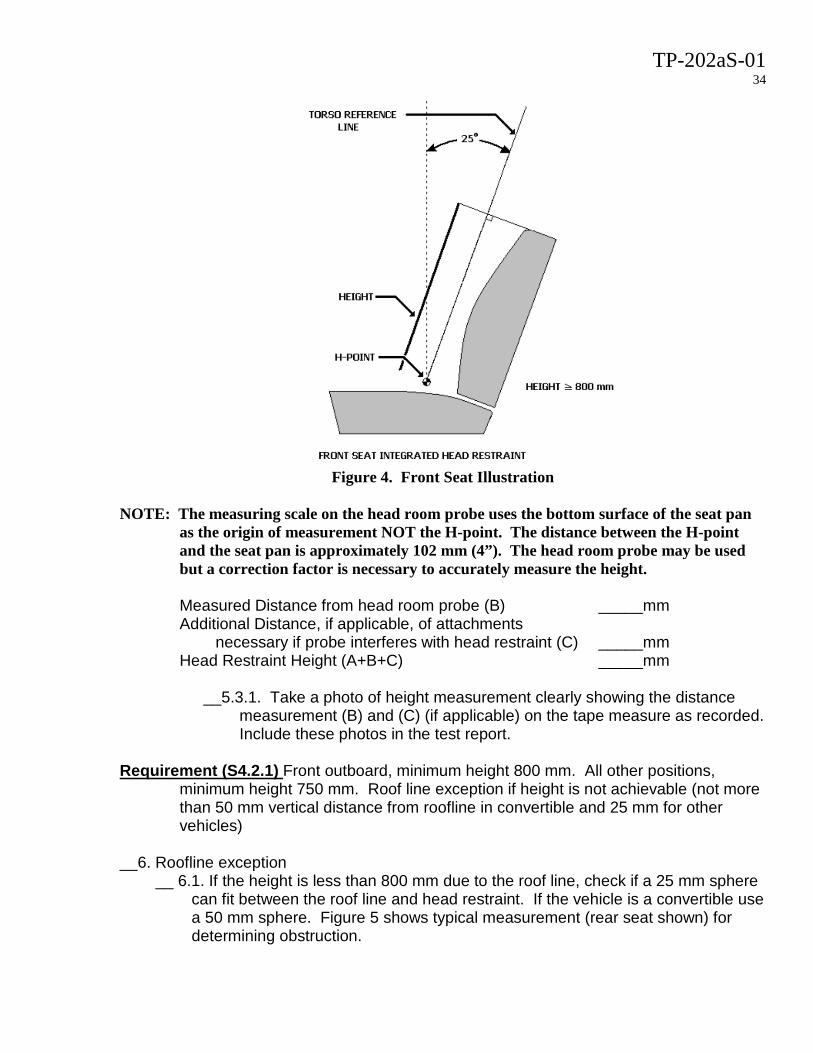
reference line (or parallel line if there is interference with head restraint) to the point where the perpendicular line from the top of the head restraint intersects the torso reference line. Figure 4 shows typical height measurement from H-Point to head restraint top. If the measured height is within 10 mm or less or the required minimum height, remove manikin, re-seat manikin, and record a second height measurement. Repeat again by removing manikin, re-seat and record a third height measurement. Then calculate the arithmetic average of the three height measurements and record the value.
TP-202aS-01 34
Figure 4. Front Seat Illustration
NOTE: The measuring scale on the head room probe uses the bottom surface of the seat pan
as the origin of measurement NOT the H-point. The distance between the H-point and the seat pan is approximately 102 mm (4”). The head room probe may be used but a correction factor is necessary to accurately measure the height.
Measured Distance from head room probe (B) _____mm Additional Distance, if applicable, of attachments
necessary if probe interferes with head restraint (C) _____mm Head Restraint Height (A+B+C) _____mm
__5.3.1. Take a photo of height measurement clearly showing the distance
measurement (B) and (C) (if applicable) on the tape measure as recorded. Include these photos in the test report.
Requirement (S4.2.1) Front outboard, minimum height 800 mm. All other positions,
minimum height 750 mm. Roof line exception if height is not achievable (not more than 50 mm vertical distance from roofline in convertible and 25 mm for other vehicles)
__6. Roofline exception
__ 6.1. If the height is less than 800 mm due to the roof line, check if a 25 mm sphere can fit between the roof line and head restraint. If the vehicle is a convertible use a 50 mm sphere. Figure 5 shows typical measurement (rear seat shown) for determining obstruction.

TP-202aS-01 35
Figure 5. Using 25 mm sphere to determine obstruction
___Sphere will not fit ___Sphere will fit ___Pass: Measured height is 800 mm minimum for front, 750 mm minimum for
all other outboard seats OR 25 mm sphere (50 mm sphere for convertibles) will not fit
___Fail: Measured height is less than 800 mm for front, 750 mm for all other outboard seats AND 25 mm sphere (50 mm sphere for convertibles) will fit
__6.2. Take photo of sphere showing a “fit” or “no fit” condition and include these photos in the test report.
__7. Front Outboard Seats: Minimum Height. For front outboard seating positions that do not meet the 800 mm height requirement and do meet the roofline exception conditions, re-adjust head restraint to the lowest position. (S4.2.1(a)(2))
__ 7.1. measure height. ____mm measured height ____Pass: Measured height is 700 mm minimum ____Fail: Measured height less than 700 mm minimum
________________________________________________ ____________ I certify that I have read and performed each instruction. Date

TP-202aS-01 36
Data Sheet 2 Width Measurement (Use for each DSP) (S4.2.2)
NHTSA No._________________ Test Date:______________ Laboratory:_______________ Test Technician(s):________________________ Designated Seating Position:__________ __1. Record ambient laboratory temperature. ________°C (18°C and 28°C) (S5)
__1.1. Conduct this test only between 18°C and 28°C. __2. After measuring the head restraint height, keep the J826 manikin seated. __3. Measure 65 mm + 3 mm below the top of the head restraint along the torso reference
line. (S5.2.2) __4. Mark the head restraint with the outline of the plane which is perpendicular to the torso
reference line and passes through the 65 mm point determined in step 3. (S5.2.2)
__5. Measure the width of the head restraint at the line created by the intersection of the plane and the head restraint. The calipers should be held at the same angle as the plane perpendicular to the torso reference line. (S5.2.2) Head Restraint Width _____mm
__6. Requirement. The width must be greater than or equal to 170 mm for vehicles without a front center DSP. If a vehicle has a front center DSP, the width of the front outboard head restraints must be greater than or equal to 254 mm (S4.2.2) ____Pass ____Fail
________________________________________________ ____________ I certify that I have read and performed each instruction. Date

TP-202aS-01 37
Data Sheet 3 Backset Measurement (Use for each DSP) (S4.2.3)
NHTSA No._________________ Test Date:______________ Laboratory:_______________ Test Technician(s):________________________ Designated Seating Position:__________ __1. Temperature.
__1.1. Conduct this test only between 18°C and 28°C. (S5) __1.2. Measure temperature
Temperature measurement ________°C __2. Seating J826 manikin.
__2.1. After measuring the head restraint height, keep the J826 manikin seated. On second and third measurements REMOVE AND RESEAT J826 MANIKIN.
__2.2. Remove the SAE J826 three-dimensional manikin’s torso weights. __2.3. Place a total of four of the SAE J826 torso weights on the torso weight hangars,
alternating placement left and right. Place the two larger HRMD torso weights, flat side down on the hangars, these weights shall be placed last.
__2.4. Mark relative position of H-point with a laser pointer. __2.5. Attach the HRMD head form to the SAE J826 three-dimensional manikin. __2.6. Verify the H-point and seatback angle has not moved within + 2 mm and + 0.5°,
respectively, by measuring any movement of the H-point from the laser reference and by any change in the seatback angle reading. If H-point or seat angle has moved more than 2 mm or 0.5 °, return to step 2 and re-seat manikin.
__2.7. Level the head form portion of the HRMD by loosening the rear knob and repositioning the head using the incorporated bubble level; then retighten knob by hand.
__2.8. Verify the torso angle is at the manufacturer’s design seat back angle and the head room probe is within 15 mm of the head restraint center line. If necessary, adjust the seat, and return to step 2 to re-seat manikin (e.g. if adjustment is done, reseating is required).
__2.9. Extend the sliding scale on the back of the head until it contacts the head restraint.
TP-202aS-01 38
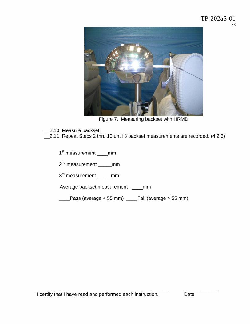
Figure 7. Measuring backset with HRMD
__2.10. Measure backset __2.11. Repeat Steps 2 thru 10 until 3 backset measurements are recorded. (4.2.3)
1st measurement ____mm 2nd measurement _____mm
3rd measurement _____mm
Average backset measurement ____mm
____Pass (average < 55 mm) ____Fail (average > 55 mm)
________________________________________________ ____________ I certify that I have read and performed each instruction. Date

TP-202aS-01 39
Data Sheet 4 Gap Measurements within Head Restraints Using a 165 mm Sphere (Use for each
DSP) (S4.2.4.1) NHTSA No._________________ Test Date:______________ Laboratory:_______________ Test Technician(s):________________________ Designated Seating Position:__________ __1. Temperature.
__1.1. Conduct this test only between 18°C and 28°C. (S5) __1.2. Measure temperature
Temperature measurement ________°C __2. Marking the 540 mm seat height.
__2.1. After measuring the height, widths, or backset measurements, keep the J826 manikin seated.
__2.2. Adjust head restraint to the lowest position. (S4.2.4.1) __2.3. Extend the head room probe of the SAE J826 three-dimensional manikin along a
line parallel to the torso reference line to a height of 540 mm. (S5.2.4.1(a)) __.2.4Extend the head room probe of the SAE J826 three-dimensional manikin along a
line parallel to the torso reference line to a height of 635 mm and mark a reference line to use for the energy absorption test. (S5.2.5(e))
__2.5. Project a plane perpendicular to the torso reference line and, mark the line that represents the intersection of the projected plane with the anterior surface of the seat back.
__2.6. Remove the SAE J826 three-dimensional manikin. __2.7. Using the manufacture’s data provided by the COTR, mark the centerline of the
seatback. __3. Marking distance from seatback center line.
__3.1. Is this seating position a front seat with a front center seating position? __Yes: Mark lines parallel to and 127 mm on each side of the seat back centerline, (S5.2.4.1(a)(1)) __No: Mark lines parallel to and 85 mm on each side of the seat back centerline, (S5.2.4.1(a)(2))

TP-202aS-01 40
Figure 8 Gap Test Area
Note: The previous steps for locating and marking the plane at 540 mm may be performed in conjunction with the “Height Measurement.”
__4. Defined Area for Gap Requirement. The area bounded by the line at a height of 540
mm, the two lines parallel to the seat back vertical centerline, and the top surface of the head restraint, is the area that must not contain any gaps larger than 60 mm. (S5.2.4.1(a)(1&2))
Figure 9. Measuring Gaps with Sphere
__5. Measuring any gaps. (S5.4.2.1)
__5.1. Place the 165 mm diameter spherical head form against any gap such that at least two points of contact are made within the area.

TP-202aS-01 41
__5.2. Apply a force of 5 N (~1 lb) maximum on the sphere. (S5.2.4.1(b)) __5.3. Measure the straight line distance between the inner edges of the two furthest
contact points (distance A in the figure 9). (S5.2.4.1(c)) Note: It may be necessary to use a transferable medium to facilitate accurate measurement of the gap using the spherical head form. Chalk water such as that which is used to paint the anthropomorphic test devices’ face in FMVSS 208 or lipstick which is used for the “heads and knees” test in FMVSS 222 would be suitable for this purpose.
__5.4. Record measurement: (4.2.4.1)
_____mm
___Pass. Gap is not greater than 25 mm ___Fail. Gap is greater than 25 mm
________________________________________________ ____________ I certify that I have read and performed each instruction. Date

TP-202aS-01 42
Data Sheet 5
Gap Measurements between Head Restraint and Seatback Using a 25 mm Cylinder (Use for each DSP) (S4.2.4.2)
NHTSA No._________________ Test Date:______________ Laboratory:_______________ Test Technician(s):________________________ Designated Seating Position:__________ __1. Temperature.
__1.1. Conduct this test only between 18°C and 28°C. (S5) __1.2. Measure temperature
Temperature measurement ________°C __2. Adjusting Head restraint. Adjust the head restraint to the lowest adjustable height. (S5.2.4.2) __3. Defined area for measurement. The area bounded by the line at a height of 540 mm,
the two lines parallel to the seat back vertical centerline (from Data Sheet 4 - Gap Measurements within Head Restraints), and any gap between the seat and bottom surface of the head restraint is defined as the area of measurement. (S5.2.4.2(a)(1&2)) (See Figure ?)
__4. Measuring Gap. (S5.2.4.2) __4.1. Using a 25 + 1 mm diameter cylinder (cylinder roughness less than 1.6 µm),
orient the cylinder such that its long axis is perpendicular to the seat back angle and in the vertical longitudinal plane of any gap. (S5.2.4.2(b))
__4.2. Apply a force of 5 N (~1 lb) maximum to the rod into each gap. (S5.2.4.2(b)) __4.3. Mark on the rod the distance of penetration. __4.4. Measure the straight line distance the rod intrudes in the gap.
_____Pass (less than 125 mm penetration on all gaps S4.2.4.2) _____Fail (over 125 mm penetration on one or more gaps)
________________________________________________ ____________ I certify that I have read and performed each instruction. Date

TP-202aS-01 43
Data Sheet 6 Energy Absorption
(Use for each DSP) (S4.2.5) NHTSA No._________________ Test Date:______________ Laboratory:_______________ Test Technician(s):________________________ Designated Seating Position:__________ __1. Temperature.
__1.1. Conduct this test only between 18°C and 28°C. (S5) __1.2. Measure temperature
Temperature measurement ________°C __2. Position the head restraint in any position of adjustment for occupant use. The
laboratory shall consult with the COTR regarding the specific position of adjustment desired. Record the position: _________________________________________
__3. Defining Impact Zone. __3.1. Mark lines parallel to and 70 mm on each side of the seat back centerline,
(S5.2.4.1(a)(2)) __3.2. Note the 635 mm height line, which was marked in Step 2.4 from Data Sheet 4. __3.3. The impact zone is defined by the two 70 mm lines from step 3.1, the 635 mm
height line lower boundary and the top of the head restraint upper boundary, See Figure 10.
Figure 10. Impact Area
__3.4. Set up impactor and head form. (S5.2.5) __3.4.1. Ensure that the accelerometer is properly mounted at the geometric center
of the head form and that the accelerometer output is properly connected to the data acquisition system.
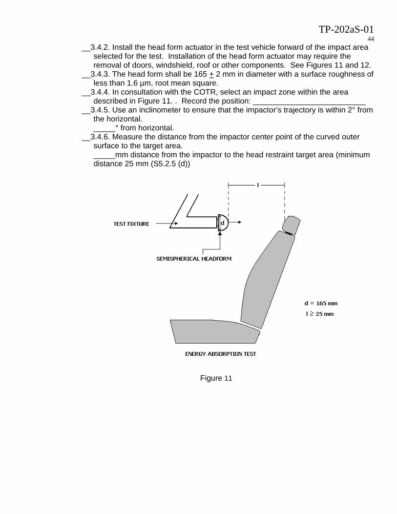
TP-202aS-01 44
__3.4.2. Install the head form actuator in the test vehicle forward of the impact area selected for the test. Installation of the head form actuator may require the removal of doors, windshield, roof or other components. See Figures 11 and 12.
__3.4.3. The head form shall be 165 + 2 mm in diameter with a surface roughness of less than 1.6 µm, root mean square.
__3.4.4. In consultation with the COTR, select an impact zone within the area described in Figure 11. . Record the position: __________________________
__3.4.5. Use an inclinometer to ensure that the impactor’s trajectory is within 2° from the horizontal. _____° from horizontal.
__3.4.6. Measure the distance from the impactor center point of the curved outer surface to the target area. _____mm distance from the impactor to the head restraint target area (minimum distance 25 mm (S5.2.5 (d))
Figure 11

TP-202aS-01 45
Figure 12 - Head form tangent to impact location (pre-test)
__3.4.7. Set the actuator to propel the head form such that an impact velocity of 23.6
kph ± 0.5 kph is achieved. __3.4.8. Activate the timing device.
__3.5. Fire the actuator and verify that the specified speed is achieved. __3.6. Processing
__3.6.1. Process the acceleration versus time data recorded from the head form accelerometer by using a "3 ms clip" computer routine to establish the maximum (3 ms clip) value of head form acceleration data using SAE J211/1 (March 1995) recommended filter class 600 and cut-off frequency of 1000 Hz. Information for the algorithms used to calculate the “3 ms clip” and digitally filter the Class 600 data collected from the energy absorption test is available from the NHTSA website. (http://www-nrd.nhtsa.dot.gov/software/signal-analysis/index.htm) Any questions pertaining to the algorithms or requests for the algorithms should be directed to the COTR. A copy of the acceleration versus time plot shall be included in the final test report. Each head restraint shall only be tested once to the energy absorption requirements.
____m/s2 deceleration calculated in the “3 ms clip” (4.2.5) ____Pass (785 m/s2 or less deceleration for more than 3 milliseconds) ____Fail (over 785 m/s2 deceleration for more than 3 milliseconds)
________________________________________________ ____________ I certify that I have read and performed each instruction. Date

TP-202aS-01 46
Data Sheet 7 Height Retention (Use for each DSP) (S4.2.6)
NHTSA No._________________ Test Date:______________ Laboratory:_______________ Test Technician(s):________________________ Designated Seating Position:__________ __1. Temperature.
__1.1. Conduct this test only between 18°C and 28°C. (S5) __1.2. Measure temperature
Temperature measurement ________°C __2. Seat Set-up(S5.2.6(a))
__2.1. Position the head restraint in the highest position of adjustment for occupant use. The backset is set at any position of adjustment.
__2.2. With the seat adjusted as required for the height measurement, locate the centerline of the head restraint (as marked previously from Data Sheet 1)
__3. Set loading device (S5.2.6(b)(1)) __3.1. Position the loading device with the attached cylindrical test device above the
head restraint. This may require the removal of the vehicle roof or other components. The COTR will be consulted prior to removing any portion of the vehicle.
__3.2. Position the 165 + 2 mm cylindrical test device with the 152 mm length (axis of revolution) horizontal and in the longitudinal plane that contains the centerline of the head restraint. The midpoint of the bottom surface of the cylinder shall contact the head restraint..
__4. Initial position. __4.1. Mark the initial position, D0 for measuring displacement (“zero” the displacement
measurement equipment) is achieved when the cylinder is touching the head restraint, without significant load. _____mark zero position (D0)
__5. Applying load __5.1. Apply and release all loads at a rate of 250 N ± 50 N/minute. __5.2. Apply the initial load of 50 N ± 1 N. (S5.2.6(b)(2)) __5.3. Maintain the load for 5 seconds. __5.4. Record the displacement of the cylindrical test device at the 50 N load, D1.
______mm (D1) __5.5. The initial displacement (D1 – D0), must be less than or equal to 25 mm. (S4.2.6)
_______Pass (D1-D0) is no more than 25 mm _______Fail (D1-D0) is greater than 25 mm
__5.6. Apply an additional load of 445 N ± 5 N for a total load of 495 N ± 5 N. (S5.2.6(c))
__5.7. Maintain the 495 N ± 5 N load for at least 5 seconds. __5.8. Reduce the load at a rate of 250 N ± 50 N/minute until the load is completely
removed. (S5.2.6(d))
TP-202aS-01 47
__5.9. Within 2 minutes of removing the load, re-apply the initial load of 50 N ± 1 N at a rate of 250 N ± 50 N/minute. (S5.2.6(e))
__5.10. Maintain this load for 5 seconds. __5.11. Measure and record displacement, D2.
______mm (D2) __5.12. Determine displacement relative to initial load, DT2 (S4.2.6)
______mm DT2 = (D1-D2) ______Pass DT2 is not greater than 13 mm. ______Fail. DT2 is greater than 13 mm.
__6. A copy of the load versus time plot, displacement versus time, and load versus displacement plot shall be included in the final test report.
________________________________________________ ____________ I certify that I have read and performed each instruction. Date

TP-202aS-01 48
Data Sheet 8 Backset Retention and Strength
(Use for each DSP) (S4.2.7) NHTSA No._________________ Test Date:______________ Laboratory:_______________ Test Technician(s):________________________ Designated Seating Position:__________ __1. Temperature.
__1.1. Conduct this test only between 18°C and 28°C. (S5) __1.2. Measure temperature
Temperature measurement ________°C __2. From the manufacturer’s supplied information, determine if the head restraint position
moves with respect to the seat when the seat is occupied. (5.2.7(a)). __2.1. If the head restraint does move, consult with COTR on bracing the head restraint
position. __3. Adjusting head restraint height. (S5.2.7(a)(1))
__3.1. If the head restraint is adjustable, adjust the front seat head restraint height to the position closest to and not less than 800 mm and the rear seat head restraint height to the position closest to and not less than 750 mm. If the head restraint, in the lowest position of adjustment, has a height greater than 800 mm for front seats or 750 mm for rear seats, adjust the head restraint to the lowest position of height adjustment. Use the method as described in Data Sheet 1 (Height Measurement) to set the head restraint height. Head restraint height: ______________
__3.2. If the rear seat head restraint is less than 750 mm in height due to roofline or backlight interference, place the restraint at the highest position of adjustment.
_____Head restraint height is less than 750 mm and positioned in highest position _____Head restraint height is 750 mm or more. __3.3. Set the backset at any position of adjustment. (S5.2.7(a)(2)) Backset adjustment: ____________________
__4. Apply Moment __4.1. Place a test device, having the back pan dimensions and torso line of the SAE
J826 three-dimensional manikin, at the previously determined H-point. Rotate the test device against the seat back so that the torso angle is the same as the torso angle of the SAE J826 three-dimensional manikin. (S5.2.7(a)(3))
__4.2. Establish the displaced torso reference line by applying, a rearward moment of 373 ± 7.5 Nm about the H-point, to the seat back. Apply the load at a rate that creates the moment rate of 187 ± 37 Nm/minute. The initial location of the moment generating load on the back pan of the test device is 290 ± 13 mm above the H-point. The force vector is to be applied perpendicular to the torso reference line. Maintain the torso reference line within 2°, and mark reference line with laser reference. Rotate the force vector with the back pan. (S5.2.7(a)(4))
Applied Moment: _____(Nm) Initial location above H-point: _____(mm) __4.3. Maintain the displaced torso reference line.

TP-202aS-01 49
__4.4. With a linear displacement transducer between the load actuator and head form installed, orient the transducer to measure head form displacement in the rearward direction perpendicular to the displaced torso reference line.
__4.5. Position the 165 mm diameter spherical head form such that the head form is tangent to the surface of the head restraint.
__4.6. The head form is positioned in the vertical direction such that the point of tangency is on the line established during the head restraint width measurement and on the marked center line of the head restraint and 65 + 3 mm below the top of the head restraint.
__4.7. Position the head form such that the applied force vector is perpendicular to the displaced torso reference line.
__4.8. Mark initial position of head form. __4.9. Apply the initial moment at a rate of 187 ± 37 Nm/minute. __4.10. Apply an initial load to create a rearward moment of 37 ± 0.7 Nm about the H-
point. (S5.2.7(a)(5)) __4.11. Maintain the load for 5 seconds, maximum.
__5. Head form displacement __5.1. Measure head form displacement with calipers. __5.2. Record the displacement of the head form, D1.
____mm displacement of head form from the initial position. (4.2.7(a)1) ____Pass. Displacement is not more than 25 mm ____Fail. Displacement is greater than 25 mm
__6. Additional moment (S5.2.7(a)(6)) __6.1. Apply an additional load to create a total rearward moment of 373 ± 7.5 Nm.
__6.1.1. Apply the additional moment at a rate of 187 ± 37 Nm/minute. __6.2. Maintain the 373 ± 7.5 Nm moment for at least 5 seconds. __6.3. Measure the displacement with calipers. __6.4. Record the displacement of the head form, D2.
____mm displacement (4.2.7(a)2) ____Pass. Displacement is not more than 102 mm ____Fail. Displacement is greater than 102 mm
__6.5. Reduce moment (S5.2.7(a)(7)) __6.5.1. Reduce the moment until it is completely removed. Maintain this condition
for not more than two minutes __6.5.1.1. The moment is reduced at a rate of 187 ± 37 Nm/minute.
__6.5.2. Increase the load until a moment of 37± 0.7 Nm is achieved. (S5.2.7(a)(8)) __6.5.2.1. The moment is applied at a rate of 187 ± 37 Nm/minute. __6.5.3. Maintain the load for 5 seconds. __6.5.4. Measure the displacement with calipers. __6.5.5. Record the displacement of the head form, D3.
____mm displacement (D3) __6.5.6. Determine displacement difference DT by subtracting D1 from D3.
____mm (DT) = (D3-D1) (4.2.7(a)3) ____Pass. Displacement, DT, is not more than 13 mm ____Fail. Displacement, DT, is greater than 13 mm
__7. Strength (S5.2.7(b)) __7.1. Increase the load applied to the head restraint, through the head form, to 885 ± 5
N, maximum.

TP-202aS-01 50
__7.2. Apply the load at the rate of 250 N ± 50 N/minute. __7.3. Maintain the 885 ± 5 N maximum load for 5 seconds, maximum. __7.4. Record the maximum load attained for 5 seconds by the head restraint.
_____N Maximum Load (4.2.7(b)) _____Pass Load is maintained load for 5 seconds _____Fail Load cannot be maintained for 5 seconds
__8. Remove the load and take post-test photographs. __9. A copy of the load versus time plot, displacement versus time plot, and load versus
displacement plot shall be included in the final test report. _______________________________________________ ____________ I certify that I have read and performed each instruction. Date
TP-202aS-01 51
Data Sheet 9
Folding or Retracting Head Restraints (Use for each DSP) (S4.2.7)
NHTSA No._________________ Test Date:______________ Laboratory:_______________ Test Technician(s):________________________ Designated Seating Position:__________ __1. Removable head restraints.
__1.1. Head restraints may be removable. Consult the owner’s manual for removal instructions.
__1.2. Photo-copy from the owner’s manual the required actions to remove the head restraint.
__1.3. The action(s) necessary to remove the head restraint must be distinct from the action(s) to adjust the head restraint. For example, pushing the same button to adjust height and to remove the restraint is not permitted.
__1.4. Verify that the head restraint removal action is distinct from the action to adjust for normal use.
__1.5. Remove the head restraint. __1.6. Reinstall the head restraint, per the owner’s manual instructions. __1.7. Include copies of the relevant pages from the owner’s manual in the test report.
__2. Non-Use Positions __2.1. Rear seat head restraints may have a position that is intended for other than
occupant use (e.g. seats fold down to provide for additional cargo space). In the non-use position the head restraint does not need to comply with height requirement.
__2.2. The head restraint must automatically return to an in-use position when the seat is occupied by a 5th percentile female or the head restraint must manually rotate at least 60° between a non-use position and an in-use position. Non-use positions are not permitted for the front seat head restraints.
__2.3. Consult the owner’s manual to determine if a non-use position is provided for the rear seat head restraints.
__2.4. Photo-copy from the owner’s manual the instructions for positioning and returning the head restraint to and from a non-use position.
__2.5. Include copies of the relevant pages from the owner’s manual in the test report. __2.6. Manual return head restraints
__2.6.1. If the head restraint is manually returned to an in-use position from a non-use position, strike a straight line on the side of the head restraint. Measure the angle created between the line and the horizontal for the head restraint in a non-use position. Position the head restraint in an in-use position and measure the angle created between the line and the horizontal.
__2.6.2. The change in angle between the initial position and the final position must be greater than or equal to 60°.

TP-202aS-01 52
__2.7. Automatic return head restraints __2.7.1. With the seat unoccupied, place the key in the ignition and turn to the “run”
position. Wait 1 minute. If the head restraint automatically moves to a non-use position, allow for the completion of the movement. If the head restraint does not automatically move to a non-use position, adjust the head restraint to a non-use position. Turn the key to the “off” position.
__2.7.2. With the head restraint in a non-use position, position a 5th percentile female Hybrid III, Subpart O, test dummy in the seat.
__2.7.3. The midsagittal plane shall be within 15 mm of the head restraint centerline and in a vertical plane parallel to the vehicle centerline.
__2.7.4. Hold the dummy’s thighs down and push rearward on the upper torso to maximize the pelvic angle.
__2.7.5. Place the legs as close as possible to 90° to the thighs. __2.7.6. Push rearward on the dummy’s knees to force the pelvis into the seat so
there is no gap between the pelvis and the seat back or until contact occurs between the back of the dummy’s calves and the front of the seat cushion such that the angle between the dummy’s thighs and legs begins to change.
__2.7.7. Place the key in the ignition in the “run” position. Wait 1 minute. Record the location of the head restraint. Turn the key to the “off” position. Remove the dummy and if necessary position the SAE J826 three-dimensional manikin to determine that the height of the head restraint is within the minimum requirement.
__3. Owners Manual __3.1. Include copies of the relevant pages from the owner’s manual in the test report. __3.2. Review the owner’s manual and verify the following:
__3.2.1. Emphasize that all occupants should place their head restraint in a proper position prior to operating the vehicle in order to prevent the risk of serious injury.
_____Pass _____Fail __3.2.2. Description of the head restraint system and identification of which seats
are equipped. _____Pass _____Fail
__3.2.3. If the head restraint is removable, instructions on how to properly remove and reinstall using a deliberate action distinct from any act necessary for adjustment.
_____Pass _____Fail __3.2.4. Warning that all head restraints must be reinstalled properly to protect
occupants. _____Pass _____Fail
__3.2.5. Describe the adjustment of the head restraints and/or seat back to achieve proper head restraint position relative the head. The description must include the following:
1) a presentation and explanation of the main components of the vehicle’s head restraints
2) the basic requirements for proper head restraint operation, including an explanation of the actions that may affect the proper functioning of the head restraints.
3) the basic requirements for proper positioning of a head restraint in relation to an occupant’s head position, including information regarding the proper

TP-202aS-01 53
positioning of the center of gravity of an occupant’s head in relation to the head restraint.
_____Pass _____Fail
_______________________________________________ ____________ I certify that I have read and performed each instruction. Date