Embed Size (px)
Citation preview
U.S. Departmentof Transportation
Federal Aviation
Administration
APRIL 3, 2014
AERONAUTICAL
INFORMATION
MANUAL
Change 1July 24, 2014
DO NOT DESTROYBASIC DATED

AIM7/24/14
Explanation of Changes E of Chg−1
Aeronautical Information ManualExplanation of Changes
Effective: July 24, 2014
a. 1−1−3. VHF Omni−Directional Range(VOR)
This change reflects the fact that some VOR receiversare capable of identifying the VOR.
b. 1−1−9. Instrument Landing System (ILS)
For those facilities that have had the middle markerdecommissioned, this change identifies a distance(1/2 mile) from the approach end of the runway forprotection of the Localizer Critical Area. This changealso removes MLS from the required phraseology toadvise pilots that the ILS Critical Area is notprotected.
c. 1−1−11. Microwave Landing System (MLS)
This change removes the reference to the ILS serviceprotection date of 2010.
d. 1−1−14. User Reports Requested onNAVAID or Global Navigation Satellite System(GNSS) Performance or Interference
4−5−6. Traffic Information Service (TIS)4−5−7. Automatic Dependent Surveillance
− Broadcast (ADS−B) Services4−5−8. Traffic Information Service (TIS) −
Broadcast (TIS−B)7−1−11. Flight Information Services (FIS)
FAA Form 8740−5, Safety Improvement Report, isno longer used to report malfunctions. Therefore,references to this form have been deleted.
e. 1−1−21. Precision Approach Systems otherthan ILS, GLS, and MLS
2−1−5. In−runway Lighting2−3−4. Taxiway Markings2−3−5. Holding Position Markings5−4−12. Radar Monitoring of Instrument
Approaches
This change removes Microwave Landing System(MLS) as an approach type.
f. 4−1−22. Airport Reservation Operationsand Special Traffic Management Programs
This change updates the contact information for theAirport Reservation Office since the CommandCenter’s relocation to Vint Hill, VA.
g. 4−3−3. Traffic Patterns
This change adds a graphic that depicts headwind,crosswind, and tailwind calculation charts.
h. 4−6−9. Contingency Actions: Weather En-counters and Aircraft System Failures
This change is made to clarify to operators that theymay request deviations per Title 14, of the Code ofFederal Regulations (14 CFR), Part 91.180 (d) afterentry into Reduced Vertical Separation Minimum(RVSM) airspace and not before.
i. 5−1−1. Preflight Preparation
This change reflects the cancellation of FAA Orders7230.16C, Pilot Education Program−Operation RainCheck, and 7230.17, Pilot Education Program−Operation Takeoff.
j. 5−3−3. Additional Reports
This change harmonizes the AIM/AeronauticalInformation Publication guidance with the mostrecent update to International Civil AviationOrganization (ICAO) Annex 2, Rules of the Air,Paragraph 3.6.2.2.
k. 5−4−3. Approach Control5−4−26. Landing Priority
This change removes references to MLS and addsreferences to include RNAV and GBAS LandingSystem (GLS) approaches.
l. 5−4−5. Instrument Approach ProcedureCharts
This change clarifies the pilot’s responsibility whiledescending on the glidepath in dependent andindependent approaches. The content and graphicswithin the Terminal Arrival Area section is alsoupdated to bring it in line with new procedures and
AIM 7/24/14
Explanation of ChangesE of Chg−2
terminology. In addition, this change provides anexplanation (both visually and verbally) as to whycircling minima may be lower than the LNAV/VNAVminima on the same approach plate.
m. 5−4−13. ILS/MLS Approaches to ParallelRunways
5−4−14. Parallel ILS/MLS Approaches (De-pendent)
This change removes references to MLS and addsreferences to include RNAV and GLS approaches. Itclarifies the runway spacing requirements for the useof final monitor controller and PRM radar. It alsoincludes a discussion of pilot procedures whenconducting simultaneous (parallel) dependent opera-tions.
n. 5−4−15. Simultaneous Parallel ILS/RNAV/GLS Approaches (Independent)
This change clarifies the runway spacing requirementwhen No Transgression Zone (NTZ) monitoring isrequired. It also clarifies monitor controller proced-ures during NTZ monitoring of simultaneous(parallel) independent approaches.
o. 5−4−16. Simultaneous Close Parallel ILS/RNAV/GLS PRM Approaches (Independent) andSimultaneous Offset Instrument Approaches(SOIA)
This change adds RNAV PRM and GLS PRMapproach discussions. It includes specific informa-
tion about the unique Flight Management Systemcoding issues for SOIA.
p. 5−4−17. Simultaneous Converging Instru-ment Approaches
This change broadens the requirements for conduct-ing converging approaches to include approachesother than ILS.
q. 5−6−1. National Security
This change now contains complete instructionsregarding Defense Visual Flight Rule positionreporting prior to Air Defense Identification Zonepenetration per 14 CFR 99.15.
r. 7−5−15. Avoid Flight in the Vicinity ofThermal Plumes (Smoke Stacks and CoolingTowers)
This change updates the terminology and providesmore detail regarding the associated hazards ofexhaust plumes.
s. 7−6−4. Unidentified Flying Object (UFO)Reports
This change removes outdated contact informationregarding the collection and/or reporting of UFOphenomena.
t. Entire publication.
Editorial/format changes were made where neces-sary. Revision bars were not used when changes areinsignificant in nature.
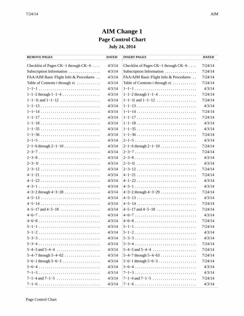
AIM7/24/14
Page Control Chart
AIM Change 1Page Control Chart
July 24, 2014
REMOVE PAGES DATED INSERT PAGES DATED
Checklist of Pages CK−1 through CK−6 . . . . 4/3/14 Checklist of Pages CK−1 through CK−6 . . . . 7/24/14
Subscription Information . . . . . . . . . . . . . . . . 4/3/14 Subscription Information . . . . . . . . . . . . . . . . 7/24/14
FAA/AIM Basic Flight Info & Procedures . . 4/3/14 FAA/AIM Basic Flight Info & Procedures . . 7/24/14
Table of Contents i through xi . . . . . . . . . . . . 4/3/14 Table of Contents i through xi . . . . . . . . . . . . 7/24/14
1−1−1 . . . . . . . . . . . . . . . . . . . . . . . . . . . . . . . 4/3/14 1−1−1 . . . . . . . . . . . . . . . . . . . . . . . . . . . . . . . 4/3/14
1−1−2 through 1−1−4 . . . . . . . . . . . . . . . . . . . 4/3/14 1−1−2 through 1−1−4 . . . . . . . . . . . . . . . . . . . 7/24/14
1−1−11 and 1−1−12 . . . . . . . . . . . . . . . . . . . . 4/3/14 1−1−11 and 1−1−12 . . . . . . . . . . . . . . . . . . . . 7/24/14
1−1−13 . . . . . . . . . . . . . . . . . . . . . . . . . . . . . . 4/3/14 1−1−13 . . . . . . . . . . . . . . . . . . . . . . . . . . . . . . 4/3/14
1−1−14 . . . . . . . . . . . . . . . . . . . . . . . . . . . . . . 4/3/14 1−1−14 . . . . . . . . . . . . . . . . . . . . . . . . . . . . . . 7/24/14
1−1−17 . . . . . . . . . . . . . . . . . . . . . . . . . . . . . . 4/3/14 1−1−17 . . . . . . . . . . . . . . . . . . . . . . . . . . . . . . 7/24/14
1−1−18 . . . . . . . . . . . . . . . . . . . . . . . . . . . . . . 4/3/14 1−1−18 . . . . . . . . . . . . . . . . . . . . . . . . . . . . . . 4/3/14
1−1−35 . . . . . . . . . . . . . . . . . . . . . . . . . . . . . . 4/3/14 1−1−35 . . . . . . . . . . . . . . . . . . . . . . . . . . . . . . 4/3/14
1−1−36 . . . . . . . . . . . . . . . . . . . . . . . . . . . . . . 4/3/14 1−1−36 . . . . . . . . . . . . . . . . . . . . . . . . . . . . . . 7/24/14
2−1−5 . . . . . . . . . . . . . . . . . . . . . . . . . . . . . . . 4/3/14 2−1−5 . . . . . . . . . . . . . . . . . . . . . . . . . . . . . . . 4/3/14
2−1−6 through 2−1−10 . . . . . . . . . . . . . . . . . . 4/3/14 2−1−6 through 2−1−10 . . . . . . . . . . . . . . . . . . 7/24/14
2−3−7 . . . . . . . . . . . . . . . . . . . . . . . . . . . . . . . 4/3/14 2−3−7 . . . . . . . . . . . . . . . . . . . . . . . . . . . . . . . 7/24/14
2−3−8 . . . . . . . . . . . . . . . . . . . . . . . . . . . . . . . 4/3/14 2−3−8 . . . . . . . . . . . . . . . . . . . . . . . . . . . . . . . 4/3/14
2−3−11 . . . . . . . . . . . . . . . . . . . . . . . . . . . . . . 4/3/14 2−3−11 . . . . . . . . . . . . . . . . . . . . . . . . . . . . . . 4/3/14
2−3−12 . . . . . . . . . . . . . . . . . . . . . . . . . . . . . . 4/3/14 2−3−12 . . . . . . . . . . . . . . . . . . . . . . . . . . . . . . 7/24/14
4−1−21 . . . . . . . . . . . . . . . . . . . . . . . . . . . . . . 4/3/14 4−1−21 . . . . . . . . . . . . . . . . . . . . . . . . . . . . . . 7/24/14
4−1−22 . . . . . . . . . . . . . . . . . . . . . . . . . . . . . . 4/3/14 4−1−22 . . . . . . . . . . . . . . . . . . . . . . . . . . . . . . 4/3/14
4−3−1 . . . . . . . . . . . . . . . . . . . . . . . . . . . . . . . 4/3/14 4−3−1 . . . . . . . . . . . . . . . . . . . . . . . . . . . . . . . 4/3/14
4−3−2 through 4−3−28 . . . . . . . . . . . . . . . . . . 4/3/14 4−3−2 through 4−3−29 . . . . . . . . . . . . . . . . . . 7/24/14
4−5−13 . . . . . . . . . . . . . . . . . . . . . . . . . . . . . . 4/3/14 4−5−13 . . . . . . . . . . . . . . . . . . . . . . . . . . . . . . 4/3/14
4−5−14 . . . . . . . . . . . . . . . . . . . . . . . . . . . . . . 4/3/14 4−5−14 . . . . . . . . . . . . . . . . . . . . . . . . . . . . . . 7/24/14
4−5−17 and 4−5−18 . . . . . . . . . . . . . . . . . . . . 4/3/14 4−5−17 and 4−5−18 . . . . . . . . . . . . . . . . . . . . 7/24/14
4−6−7 . . . . . . . . . . . . . . . . . . . . . . . . . . . . . . . 4/3/14 4−6−7 . . . . . . . . . . . . . . . . . . . . . . . . . . . . . . . 4/3/14
4−6−8 . . . . . . . . . . . . . . . . . . . . . . . . . . . . . . . 4/3/14 4−6−8 . . . . . . . . . . . . . . . . . . . . . . . . . . . . . . . 7/24/14
5−1−1 . . . . . . . . . . . . . . . . . . . . . . . . . . . . . . . 4/3/14 5−1−1 . . . . . . . . . . . . . . . . . . . . . . . . . . . . . . . 7/24/14
5−1−2 . . . . . . . . . . . . . . . . . . . . . . . . . . . . . . . 4/3/14 5−1−2 . . . . . . . . . . . . . . . . . . . . . . . . . . . . . . . 4/3/14
5−3−3 . . . . . . . . . . . . . . . . . . . . . . . . . . . . . . . 4/3/14 5−3−3 . . . . . . . . . . . . . . . . . . . . . . . . . . . . . . . 4/3/14
5−3−4 . . . . . . . . . . . . . . . . . . . . . . . . . . . . . . . 4/3/14 5−3−4 . . . . . . . . . . . . . . . . . . . . . . . . . . . . . . . 7/24/14
5−4−3 and 5−4−4 . . . . . . . . . . . . . . . . . . . . . . 4/3/14 5−4−3 and 5−4−4 . . . . . . . . . . . . . . . . . . . . . . 7/24/14
5−4−7 through 5−4−62 . . . . . . . . . . . . . . . . . . 4/3/14 5−4−7 through 5−4−63 . . . . . . . . . . . . . . . . . . 7/24/14
5−6−1 through 5−6−3 . . . . . . . . . . . . . . . . . . . 4/3/14 5−6−1 through 5−6−3 . . . . . . . . . . . . . . . . . . . 7/24/14
5−6−4 . . . . . . . . . . . . . . . . . . . . . . . . . . . . . . . 4/3/14 5−6−4 . . . . . . . . . . . . . . . . . . . . . . . . . . . . . . . 4/3/14
7−1−3 . . . . . . . . . . . . . . . . . . . . . . . . . . . . . . . 4/3/14 7−1−3 . . . . . . . . . . . . . . . . . . . . . . . . . . . . . . . 4/3/14
7−1−4 and 7−1−5 . . . . . . . . . . . . . . . . . . . . . . 4/3/14 7−1−4 and 7−1−5 . . . . . . . . . . . . . . . . . . . . . . 7/24/14
7−1−6 . . . . . . . . . . . . . . . . . . . . . . . . . . . . . . . 4/3/14 7−1−6 . . . . . . . . . . . . . . . . . . . . . . . . . . . . . . . 4/3/14

AIM 7/24/14
2 Page Control Chart
REMOVE PAGES DATED INSERT PAGES DATED
7−1−23 . . . . . . . . . . . . . . . . . . . . . . . . . . . . . . 4/3/14 7−1−23 . . . . . . . . . . . . . . . . . . . . . . . . . . . . . . 4/3/14
7−1−24 and 7−1−25 . . . . . . . . . . . . . . . . . . . . 4/3/14 7−1−24 and 7−1−25 . . . . . . . . . . . . . . . . . . . . 7/24/14
7−1−26 . . . . . . . . . . . . . . . . . . . . . . . . . . . . . . 4/3/14 7−1−26 . . . . . . . . . . . . . . . . . . . . . . . . . . . . . . 4/3/14
7−1−41 . . . . . . . . . . . . . . . . . . . . . . . . . . . . . . 4/3/14 7−1−41 . . . . . . . . . . . . . . . . . . . . . . . . . . . . . . 4/3/14
7−1−42 . . . . . . . . . . . . . . . . . . . . . . . . . . . . . . 4/3/14 7−1−42 . . . . . . . . . . . . . . . . . . . . . . . . . . . . . . 7/24/14
7−1−43 . . . . . . . . . . . . . . . . . . . . . . . . . . . . . . 4/3/14 7−1−43 . . . . . . . . . . . . . . . . . . . . . . . . . . . . . . 4/3/14
7−1−44 . . . . . . . . . . . . . . . . . . . . . . . . . . . . . . 4/3/14 7−1−44 . . . . . . . . . . . . . . . . . . . . . . . . . . . . . . 7/24/14
7−1−59 . . . . . . . . . . . . . . . . . . . . . . . . . . . . . . 4/3/14 7−1−59 . . . . . . . . . . . . . . . . . . . . . . . . . . . . . . 4/3/14
7−1−60 . . . . . . . . . . . . . . . . . . . . . . . . . . . . . . 4/3/14 7−1−60 . . . . . . . . . . . . . . . . . . . . . . . . . . . . . . 7/24/14
7−5−13 and 7−5−14 . . . . . . . . . . . . . . . . . . . . 4/3/14 7−5−13 and 7−5−14 . . . . . . . . . . . . . . . . . . . . 7/24/14
7−6−3 . . . . . . . . . . . . . . . . . . . . . . . . . . . . . . . 7/24/14 7−6−3 . . . . . . . . . . . . . . . . . . . . . . . . . . . . . . . 7/24/14
PCG−1 . . . . . . . . . . . . . . . . . . . . . . . . . . . . . . 4/3/14 PCG−1 and PCG−2 . . . . . . . . . . . . . . . . . . . . 7/24/14
PCG A−1 through PCG W−2 . . . . . . . . . . . . . 4/3/14 PCG A−1 through PCG W−2 . . . . . . . . . . . . . 7/24/14
Index I−1 through I−13 . . . . . . . . . . . . . . . . . 4/3/14 Index I−1 through I−13 . . . . . . . . . . . . . . . . . 7/24/14

7/24/14
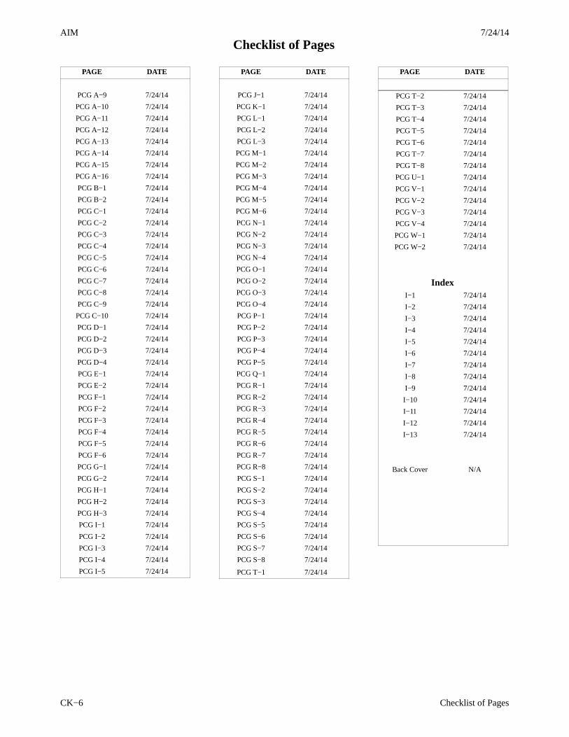
Checklist of PagesAIM
Checklist of Pages CK−1
PAGE DATE
Cover 7/24/14
Record of Changes N/A
Exp of Chg−1 7/24/14
Exp of Chg−2 7/24/14
Checklist of PagesCK−1 7/24/14
CK−2 7/24/14
CK−3 7/24/14
CK−4 7/24/14
CK−5 7/24/14
CK−6 7/24/14
Subscription Info 7/24/14
Comments/Corr 4/3/14
Comments/Corr 4/3/14
Basic Flight Info 7/24/14
Publication Policy 4/3/14
Reg & Advis Cir 4/3/14
Table of Contentsi 7/24/14
ii 7/24/14
iii 7/24/14
iv 7/24/14
v 7/24/14
vi 7/24/14
vii 7/24/14
viii 7/24/14
ix 7/24/14
x 7/24/14
xi 7/24/14
Chapter 1. Air NavigationSection 1. Navigation Aids
1−1−1 4/3/14
1−1−2 7/24/14
1−1−3 7/24/14
1−1−4 7/24/14
1−1−5 4/3/14
1−1−6 4/3/14
1−1−7 4/3/14
1−1−8 4/3/14
1−1−9 4/3/14
1−1−10 4/3/14
1−1−11 7/24/14
PAGE DATE
1−1−12 7/24/14
1−1−13 4/3/14
1−1−14 7/24/14
1−1−15 4/3/14
1−1−16 4/3/14
1−1−17 7/24/14
1−1−18 4/3/14
1−1−19 4/3/14
1−1−20 4/3/14
1−1−21 4/3/14
1−1−22 4/3/14
1−1−23 4/3/14
1−1−24 4/3/14
1−1−25 4/3/14
1−1−26 4/3/14
1−1−27 4/3/14
1−1−28 4/3/14
1−1−29 4/3/14
1−1−30 4/3/14
1−1−31 4/3/14
1−1−32 4/3/14
1−1−33 4/3/14
1−1−34 4/3/14
1−1−35 4/3/14
1−1−36 7/24/14
1−1−37 4/3/14
Section 2. Area Navigation(RNAV) and Required
Navigation Performance(RNP)
1−2−1 4/3/14
1−2−2 4/3/14
1−2−3 4/3/14
1−2−4 4/3/14
1−2−5 4/3/14
1−2−6 4/3/14
1−2−7 4/3/14
PAGE DATE
Chapter 2. AeronauticalLighting and Other Airport
Visual AidsSection 1. Airport Lighting
Aids2−1−1 4/3/14
2−1−2 4/3/14
2−1−3 4/3/14
2−1−4 4/3/14
2−1−5 4/3/14
2−1−6 4/3/14
2−1−7 4/3/14
2−1−8 4/3/14
2−1−9 4/3/14
2−1−10 4/3/14
2−1−11 4/3/14
2−1−12 4/3/14
2−1−13 4/3/14
2−1−14 4/3/14
2−1−15 4/3/14
Section 2. Air Navigation andObstruction Lighting2−2−1 4/3/14
2−2−2 4/3/14
Section 3. Airport MarkingAids and Signs
2−3−1 4/3/14
2−3−2 4/3/14
2−3−3 4/3/14
2−3−4 4/3/14
2−3−5 4/3/14
2−3−6 4/3/14
2−3−7 7/24/14
2−3−8 4/3/14
2−3−9 4/3/14
2−3−10 4/3/14
2−3−11 4/3/14
2−3−12 7/24/14
2−3−13 4/3/14
2−3−14 4/3/14
2−3−15 4/3/14
2−3−16 4/3/14
2−3−17 4/3/14
2−3−18 4/3/14
2−3−19 4/3/14
2−3−20 4/3/14
2−3−21 4/3/14
7/24/14AIM
Checklist of Pages
Checklist of PagesCK−2
PAGE DATE
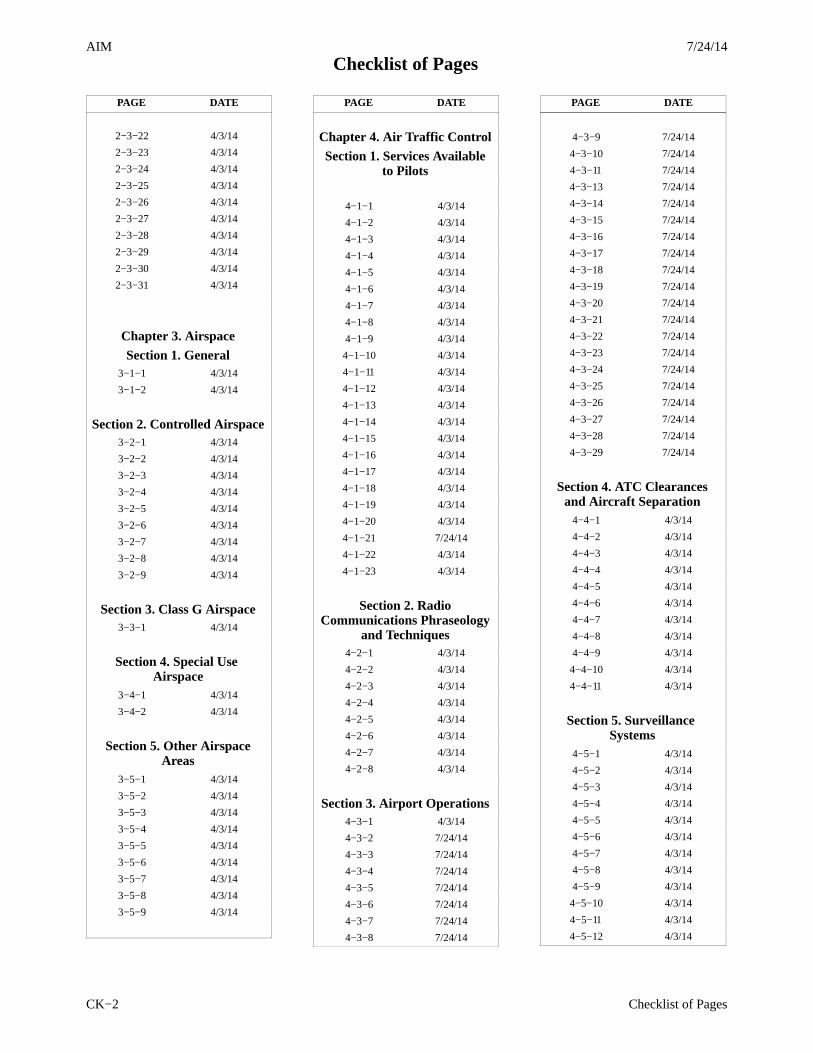
2−3−22 4/3/14
2−3−23 4/3/14
2−3−24 4/3/14
2−3−25 4/3/14
2−3−26 4/3/14
2−3−27 4/3/14
2−3−28 4/3/14
2−3−29 4/3/14
2−3−30 4/3/14
2−3−31 4/3/14
Chapter 3. AirspaceSection 1. General
3−1−1 4/3/14
3−1−2 4/3/14
Section 2. Controlled Airspace3−2−1 4/3/14
3−2−2 4/3/14
3−2−3 4/3/14
3−2−4 4/3/14
3−2−5 4/3/14
3−2−6 4/3/14
3−2−7 4/3/14
3−2−8 4/3/14
3−2−9 4/3/14
Section 3. Class G Airspace3−3−1 4/3/14
Section 4. Special Use Airspace
3−4−1 4/3/14
3−4−2 4/3/14
Section 5. Other AirspaceAreas
3−5−1 4/3/14
3−5−2 4/3/14
3−5−3 4/3/14
3−5−4 4/3/14
3−5−5 4/3/14
3−5−6 4/3/14
3−5−7 4/3/14
3−5−8 4/3/14
3−5−9 4/3/14
PAGE DATE
Chapter 4. Air Traffic ControlSection 1. Services Available
to Pilots
4−1−1 4/3/14
4−1−2 4/3/14
4−1−3 4/3/14
4−1−4 4/3/14
4−1−5 4/3/14
4−1−6 4/3/14
4−1−7 4/3/14
4−1−8 4/3/14
4−1−9 4/3/14
4−1−10 4/3/14
4−1−11 4/3/14
4−1−12 4/3/14
4−1−13 4/3/14
4−1−14 4/3/14
4−1−15 4/3/14
4−1−16 4/3/14
4−1−17 4/3/14
4−1−18 4/3/14
4−1−19 4/3/14
4−1−20 4/3/14
4−1−21 7/24/14
4−1−22 4/3/14
4−1−23 4/3/14
Section 2. RadioCommunications Phraseology
and Techniques4−2−1 4/3/14
4−2−2 4/3/14
4−2−3 4/3/14
4−2−4 4/3/14
4−2−5 4/3/14
4−2−6 4/3/14
4−2−7 4/3/14
4−2−8 4/3/14
Section 3. Airport Operations4−3−1 4/3/14
4−3−2 7/24/14
4−3−3 7/24/14
4−3−4 7/24/14
4−3−5 7/24/14
4−3−6 7/24/14
4−3−7 7/24/14
4−3−8 7/24/14
PAGE DATE
4−3−9 7/24/14
4−3−10 7/24/14
4−3−11 7/24/14
4−3−13 7/24/14
4−3−14 7/24/14
4−3−15 7/24/14
4−3−16 7/24/14
4−3−17 7/24/14
4−3−18 7/24/14
4−3−19 7/24/14
4−3−20 7/24/14
4−3−21 7/24/14
4−3−22 7/24/14
4−3−23 7/24/14
4−3−24 7/24/14
4−3−25 7/24/14
4−3−26 7/24/14
4−3−27 7/24/14
4−3−28 7/24/14
4−3−29 7/24/14
Section 4. ATC Clearancesand Aircraft Separation
4−4−1 4/3/14
4−4−2 4/3/14
4−4−3 4/3/14
4−4−4 4/3/14
4−4−5 4/3/14
4−4−6 4/3/14
4−4−7 4/3/14
4−4−8 4/3/14
4−4−9 4/3/14
4−4−10 4/3/14
4−4−11 4/3/14
Section 5. Surveillance Systems
4−5−1 4/3/14
4−5−2 4/3/14
4−5−3 4/3/14
4−5−4 4/3/14
4−5−5 4/3/14
4−5−6 4/3/14
4−5−7 4/3/14
4−5−8 4/3/14
4−5−9 4/3/14
4−5−10 4/3/14
4−5−11 4/3/14
4−5−12 4/3/14
7/24/14
Checklist of PagesAIM
Checklist of Pages CK−3
PAGE DATE
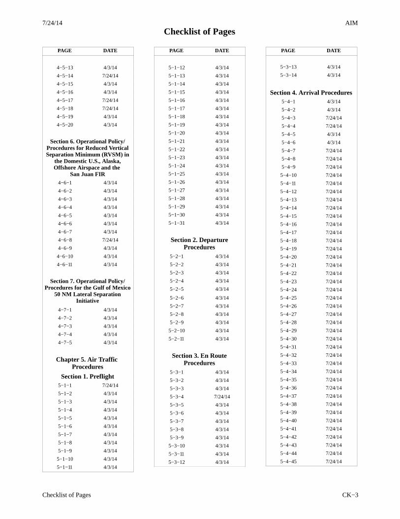
4−5−13 4/3/14
4−5−14 7/24/14
4−5−15 4/3/14
4−5−16 4/3/14
4−5−17 7/24/14
4−5−18 7/24/14
4−5−19 4/3/14
4−5−20 4/3/14
Section 6. Operational Policy/Procedures for Reduced VerticalSeparation Minimum (RVSM) in
the Domestic U.S., Alaska,Offshore Airspace and the
San Juan FIR4−6−1 4/3/14
4−6−2 4/3/14
4−6−3 4/3/14
4−6−4 4/3/14
4−6−5 4/3/14
4−6−6 4/3/14
4−6−7 4/3/14
4−6−8 7/24/14
4−6−9 4/3/14
4−6−10 4/3/14
4−6−11 4/3/14
Section 7. Operational Policy/Procedures for the Gulf of Mexico
50 NM Lateral SeparationInitiative
4−7−1 4/3/14
4−7−2 4/3/14
4−7−3 4/3/14
4−7−4 4/3/14
4−7−5 4/3/14
Chapter 5. Air Traffic Procedures
Section 1. Preflight5−1−1 7/24/14
5−1−2 4/3/14
5−1−3 4/3/14
5−1−4 4/3/14
5−1−5 4/3/14
5−1−6 4/3/14
5−1−7 4/3/14
5−1−8 4/3/14
5−1−9 4/3/14
5−1−10 4/3/14
5−1−11 4/3/14
PAGE DATE
5−1−12 4/3/14
5−1−13 4/3/14
5−1−14 4/3/14
5−1−15 4/3/14
5−1−16 4/3/14
5−1−17 4/3/14
5−1−18 4/3/14
5−1−19 4/3/14
5−1−20 4/3/14
5−1−21 4/3/14
5−1−22 4/3/14
5−1−23 4/3/14
5−1−24 4/3/14
5−1−25 4/3/14
5−1−26 4/3/14
5−1−27 4/3/14
5−1−28 4/3/14
5−1−29 4/3/14
5−1−30 4/3/14
5−1−31 4/3/14
Section 2. DepartureProcedures
5−2−1 4/3/14
5−2−2 4/3/14
5−2−3 4/3/14
5−2−4 4/3/14
5−2−5 4/3/14
5−2−6 4/3/14
5−2−7 4/3/14
5−2−8 4/3/14
5−2−9 4/3/14
5−2−10 4/3/14
5−2−11 4/3/14
Section 3. En RouteProcedures
5−3−1 4/3/14
5−3−2 4/3/14
5−3−3 4/3/14
5−3−4 7/24/14
5−3−5 4/3/14
5−3−6 4/3/14
5−3−7 4/3/14
5−3−8 4/3/14
5−3−9 4/3/14
5−3−10 4/3/14
5−3−11 4/3/14
5−3−12 4/3/14
PAGE DATE
5−3−13 4/3/14
5−3−14 4/3/14
Section 4. Arrival Procedures5−4−1 4/3/14
5−4−2 4/3/14
5−4−3 7/24/14
5−4−4 7/24/14
5−4−5 4/3/14
5−4−6 4/3/14
5−4−7 7/24/14
5−4−8 7/24/14
5−4−9 7/24/14
5−4−10 7/24/14
5−4−11 7/24/14
5−4−12 7/24/14
5−4−13 7/24/14
5−4−14 7/24/14
5−4−15 7/24/14
5−4−16 7/24/14
5−4−17 7/24/14
5−4−18 7/24/14
5−4−19 7/24/14
5−4−20 7/24/14
5−4−21 7/24/14
5−4−22 7/24/14
5−4−23 7/24/14
5−4−24 7/24/14
5−4−25 7/24/14
5−4−26 7/24/14
5−4−27 7/24/14
5−4−28 7/24/14
5−4−29 7/24/14
5−4−30 7/24/14
5−4−31 7/24/14
5−4−32 7/24/14
5−4−33 7/24/14
5−4−34 7/24/14
5−4−35 7/24/14
5−4−36 7/24/14
5−4−37 7/24/14
5−4−38 7/24/14
5−4−39 7/24/14
5−4−40 7/24/14
5−4−41 7/24/14
5−4−42 7/24/14
5−4−43 7/24/14
5−4−44 7/24/14
5−4−45 7/24/14
7/24/14AIM
Checklist of Pages
Checklist of PagesCK−4
PAGE DATE
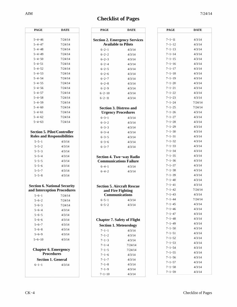
5−4−46 7/24/14
5−4−47 7/24/14
5−4−48 7/24/14
5−4−49 7/24/14
5−4−50 7/24/14
5−4−51 7/24/14
5−4−52 7/24/14
5−4−53 7/24/14
5−4−54 7/24/14
5−4−55 7/24/14
5−4−56 7/24/14
5−4−57 7/24/14
5−4−58 7/24/14
5−4−59 7/24/14
5−4−60 7/24/14
5−4−61 7/24/14
5−4−62 7/24/14
5−4−63 7/24/14
Section 5. Pilot/ControllerRoles and Responsibilities
5−5−1 4/3/14
5−5−2 4/3/14
5−5−3 4/3/14
5−5−4 4/3/14
5−5−5 4/3/14
5−5−6 4/3/14
5−5−7 4/3/14
5−5−8 4/3/14
Section 6. National Securityand Interception Procedures
5−6−1 7/24/14
5−6−2 7/24/14
5−6−3 7/24/14
5−6−4 4/3/14
5−6−5 4/3/14
5−6−6 4/3/14
5−6−7 4/3/14
5−6−8 4/3/14
5−6−9 4/3/14
5−6−10 4/3/14
Chapter 6. Emergency Procedures
Section 1. General6−1−1 4/3/14
PAGE DATE
Section 2. Emergency ServicesAvailable to Pilots
6−2−1 4/3/14
6−2−2 4/3/14
6−2−3 4/3/14
6−2−4 4/3/14
6−2−5 4/3/14
6−2−6 4/3/14
6−2−7 4/3/14
6−2−8 4/3/14
6−2−9 4/3/14
6−2−10 4/3/14
6−2−11 4/3/14
Section 3. Distress andUrgency Procedures6−3−1 4/3/14
6−3−2 4/3/14
6−3−3 4/3/14
6−3−4 4/3/14
6−3−5 4/3/14
6−3−6 4/3/14
6−3−7 4/3/14
Section 4. Two−way RadioCommunications Failure
6−4−1 4/3/14
6−4−2 4/3/14
Section 5. Aircraft Rescueand Fire FightingCommunications
6−5−1 4/3/14
6−5−2 4/3/14
Chapter 7. Safety of FlightSection 1. Meteorology7−1−1 4/3/14
7−1−2 4/3/14
7−1−3 4/3/14
7−1−4 7/24/14
7−1−5 7/24/14
7−1−6 4/3/14
7−1−7 4/3/14
7−1−8 4/3/14
7−1−9 4/3/14
7−1−10 4/3/14
PAGE DATE
7−1−11 4/3/14
7−1−12 4/3/14
7−1−13 4/3/14
7−1−14 4/3/14
7−1−15 4/3/14
7−1−16 4/3/14
7−1−17 4/3/14
7−1−18 4/3/14
7−1−19 4/3/14
7−1−20 4/3/14
7−1−21 4/3/14
7−1−22 4/3/14
7−1−23 4/3/14
7−1−24 7/24/14
7−1−25 7/24/14
7−1−26 4/3/14
7−1−27 4/3/14
7−1−28 4/3/14
7−1−29 4/3/14
7−1−30 4/3/14
7−1−31 4/3/14
7−1−32 4/3/14
7−1−33 4/3/14
7−1−34 4/3/14
7−1−35 4/3/14
7−1−36 4/3/14
7−1−37 4/3/14
7−1−38 4/3/14
7−1−39 4/3/14
7−1−40 4/3/14
7−1−41 4/3/14
7−1−42 7/24/14
7−1−43 4/3/14
7−1−44 7/24/14
7−1−45 4/3/14
7−1−46 4/3/14
7−1−47 4/3/14
7−1−48 4/3/14
7−1−49 4/3/14
7−1−50 4/3/14
7−1−51 4/3/14
7−1−52 4/3/14
7−1−53 4/3/14
7−1−54 4/3/14
7−1−55 4/3/14
7−1−56 4/3/14
7−1−57 4/3/14
7−1−58 4/3/14
7−1−59 4/3/14
7/24/14
Checklist of PagesAIM
Checklist of Pages CK−5
PAGE DATE
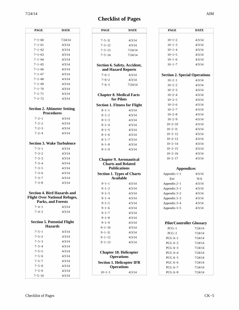
7−1−60 7/24/14
7−1−61 4/3/14
7−1−62 4/3/14
7−1−63 4/3/14
7−1−64 4/3/14
7−1−65 4/3/14
7−1−66 4/3/14
7−1−67 4/3/14
7−1−68 4/3/14
7−1−69 4/3/14
7−1−70 4/3/14
7−1−71 4/3/14
7−1−72 4/3/14
Section 2. Altimeter Setting Procedures
7−2−1 4/3/14
7−2−2 4/3/14
7−2−3 4/3/14
7−2−4 4/3/14
Section 3. Wake Turbulence7−3−1 4/3/14
7−3−2 4/3/14
7−3−3 4/3/14
7−3−4 4/3/14
7−3−5 4/3/14
7−3−6 4/3/14
7−3−7 4/3/14
7−3−8 4/3/14
Section 4. Bird Hazards andFlight Over National Refuges,
Parks, and Forests7−4−1 4/3/14
7−4−2 4/3/14
Section 5. Potential FlightHazards
7−5−1 4/3/14
7−5−2 4/3/14
7−5−3 4/3/14
7−5−4 4/3/14
7−5−5 4/3/14
7−5−6 4/3/14
7−5−7 4/3/14
7−5−8 4/3/14
7−5−9 4/3/14
7−5−10 4/3/14
PAGE DATE
7−5−11 4/3/14
7−5−12 4/3/14
7−5−13 7/24/14
7−5−14 7/24/14
Section 6. Safety, Accident,and Hazard Reports7−6−1 4/3/14
7−6−2 4/3/14
7−6−3 7/24/14
Chapter 8. Medical Facts for Pilots
Section 1. Fitness for Flight8−1−1 4/3/14
8−1−2 4/3/14
8−1−3 4/3/14
8−1−4 4/3/14
8−1−5 4/3/14
8−1−6 4/3/14
8−1−7 4/3/14
8−1−8 4/3/14
8−1−9 4/3/14
Chapter 9. AeronauticalCharts and Related
PublicationsSection 1. Types of Charts
Available9−1−1 4/3/14
9−1−2 4/3/14
9−1−3 4/3/14
9−1−4 4/3/14
9−1−5 4/3/14
9−1−6 4/3/14
9−1−7 4/3/14
9−1−8 4/3/14
9−1−9 4/3/14
9−1−10 4/3/14
9−1−11 4/3/14
9−1−12 4/3/14
9−1−13 4/3/14
Chapter 10. HelicopterOperations
Section 1. Helicopter IFROperations
10−1−1 4/3/14
PAGE DATE
10−1−2 4/3/14
10−1−3 4/3/14
10−1−4 4/3/14
10−1−5 4/3/14
10−1−6 4/3/14
10−1−7 4/3/14
Section 2. Special Operations10−2−1 4/3/14
10−2−2 4/3/14
10−2−3 4/3/14
10−2−4 4/3/14
10−2−5 4/3/14
10−2−6 4/3/14
10−2−7 4/3/14
10−2−8 4/3/14
10−2−9 4/3/14
10−2−10 4/3/14
10−2−11 4/3/14
10−2−12 4/3/14
10−2−13 4/3/14
10−2−14 4/3/14
10−2−15 4/3/14
10−2−16 4/3/14
10−2−17 4/3/14
AppendicesAppendix 1−1 4/3/14
Env N/A
Appendix 2−1 4/3/14
Appendix 3−1 4/3/14
Appendix 3−2 4/3/14
Appendix 3−3 4/3/14
Appendix 3−4 4/3/14
Appendix 3−5 4/3/14
Pilot/Controller GlossaryPCG−1 7/24/14
PCG−2 7/24/14
PCG A−1 7/24/14
PCG A−2 7/24/14
PCG A−3 7/24/14
PCG A−4 7/24/14
PCG A−5 7/24/14
PGC A−6 7/24/14
PCG A−7 7/24/14
PCG A−8 7/24/14
7/24/14AIM
Checklist of Pages
Checklist of PagesCK−6
PAGE DATE
PCG A−9 7/24/14
PCG A−10 7/24/14
PCG A−11 7/24/14
PCG A−12 7/24/14
PCG A−13 7/24/14
PCG A−14 7/24/14
PCG A−15 7/24/14
PCG A−16 7/24/14
PCG B−1 7/24/14
PCG B−2 7/24/14
PCG C−1 7/24/14
PCG C−2 7/24/14
PCG C−3 7/24/14
PCG C−4 7/24/14
PCG C−5 7/24/14
PCG C−6 7/24/14
PCG C−7 7/24/14
PCG C−8 7/24/14
PCG C−9 7/24/14
PCG C−10 7/24/14
PCG D−1 7/24/14
PCG D−2 7/24/14
PCG D−3 7/24/14
PCG D−4 7/24/14
PCG E−1 7/24/14
PCG E−2 7/24/14
PCG F−1 7/24/14
PCG F−2 7/24/14
PCG F−3 7/24/14
PCG F−4 7/24/14
PCG F−5 7/24/14
PCG F−6 7/24/14
PCG G−1 7/24/14
PCG G−2 7/24/14
PCG H−1 7/24/14
PCG H−2 7/24/14
PCG H−3 7/24/14
PCG I−1 7/24/14
PCG I−2 7/24/14
PCG I−3 7/24/14
PCG I−4 7/24/14
PCG I−5 7/24/14
PAGE DATE
PCG J−1 7/24/14
PCG K−1 7/24/14
PCG L−1 7/24/14
PCG L−2 7/24/14
PCG L−3 7/24/14
PCG M−1 7/24/14
PCG M−2 7/24/14
PCG M−3 7/24/14
PCG M−4 7/24/14
PCG M−5 7/24/14
PCG M−6 7/24/14
PCG N−1 7/24/14
PCG N−2 7/24/14
PCG N−3 7/24/14
PCG N−4 7/24/14
PCG O−1 7/24/14
PCG O−2 7/24/14
PCG O−3 7/24/14
PCG O−4 7/24/14
PCG P−1 7/24/14
PCG P−2 7/24/14
PCG P−3 7/24/14
PCG P−4 7/24/14
PCG P−5 7/24/14
PCG Q−1 7/24/14
PCG R−1 7/24/14
PCG R−2 7/24/14
PCG R−3 7/24/14
PCG R−4 7/24/14
PCG R−5 7/24/14
PCG R−6 7/24/14
PCG R−7 7/24/14
PCG R−8 7/24/14
PCG S−1 7/24/14
PCG S−2 7/24/14
PCG S−3 7/24/14
PCG S−4 7/24/14
PCG S−5 7/24/14
PCG S−6 7/24/14
PCG S−7 7/24/14
PCG S−8 7/24/14
PCG T−1 7/24/14
PAGE DATE
PCG T−2 7/24/14
PCG T−3 7/24/14
PCG T−4 7/24/14
PCG T−5 7/24/14
PCG T−6 7/24/14
PCG T−7 7/24/14
PCG T−8 7/24/14
PCG U−1 7/24/14
PCG V−1 7/24/14
PCG V−2 7/24/14
PCG V−3 7/24/14
PCG V−4 7/24/14
PCG W−1 7/24/14
PCG W−2 7/24/14
IndexI−1 7/24/14
I−2 7/24/14
I−3 7/24/14
I−4 7/24/14
I−5 7/24/14
I−6 7/24/14
I−7 7/24/14
I−8 7/24/14
I−9 7/24/14
I−10 7/24/14
I−11 7/24/14
I−12 7/24/14
I−13 7/24/14
Back Cover N/A
AIM7/24/14
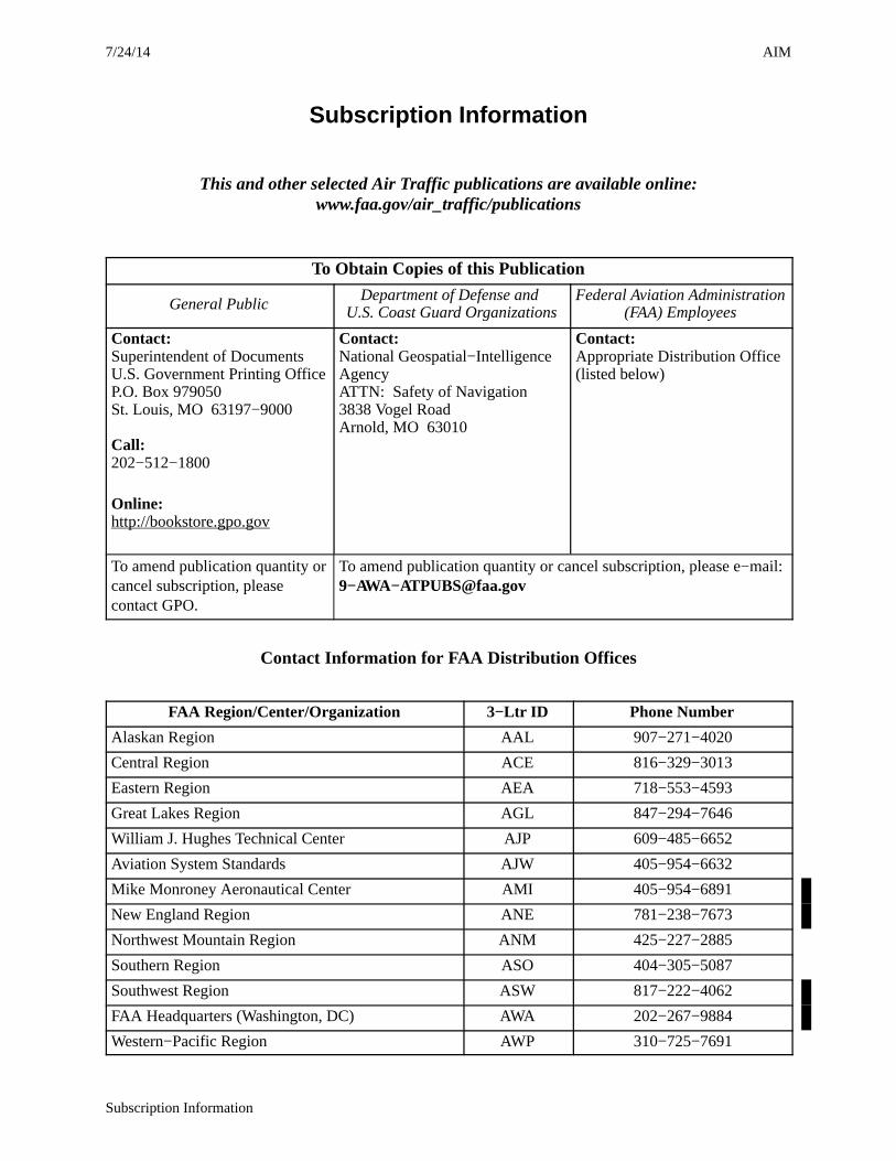
Subscription Information
Subscription Information
This and other selected Air Traffic publications are available online:www.faa.gov/air_traffic/publications
To Obtain Copies of this Publication
General PublicDepartment of Defense and
U.S. Coast Guard OrganizationsFederal Aviation Administration
(FAA) Employees
Contact:Superintendent of DocumentsU.S. Government Printing OfficeP.O. Box 979050St. Louis, MO 63197−9000
Call:202−512−1800
Online:http://bookstore.gpo.gov
Contact:National Geospatial−IntelligenceAgencyATTN: Safety of Navigation3838 Vogel RoadArnold, MO 63010
Contact:Appropriate Distribution Office(listed below)
To amend publication quantity orcancel subscription, pleasecontact GPO.
To amend publication quantity or cancel subscription, please e−mail:9−AWA−[email protected]
Contact Information for FAA Distribution Offices
FAA Region/Center/Organization 3−Ltr ID Phone Number
Alaskan Region AAL 907−271−4020
Central Region ACE 816−329−3013
Eastern Region AEA 718−553−4593
Great Lakes Region AGL 847−294−7646
William J. Hughes Technical Center AJP 609−485−6652
Aviation System Standards AJW 405−954−6632
Mike Monroney Aeronautical Center AMI 405−954−6891
New England Region ANE 781−238−7673
Northwest Mountain Region ANM 425−227−2885
Southern Region ASO 404−305−5087
Southwest Region ASW 817−222−4062
FAA Headquarters (Washington, DC) AWA 202−267−9884
Western−Pacific Region AWP 310−725−7691

AIM7/24/14
Basic Flight Information and ATC Procedures
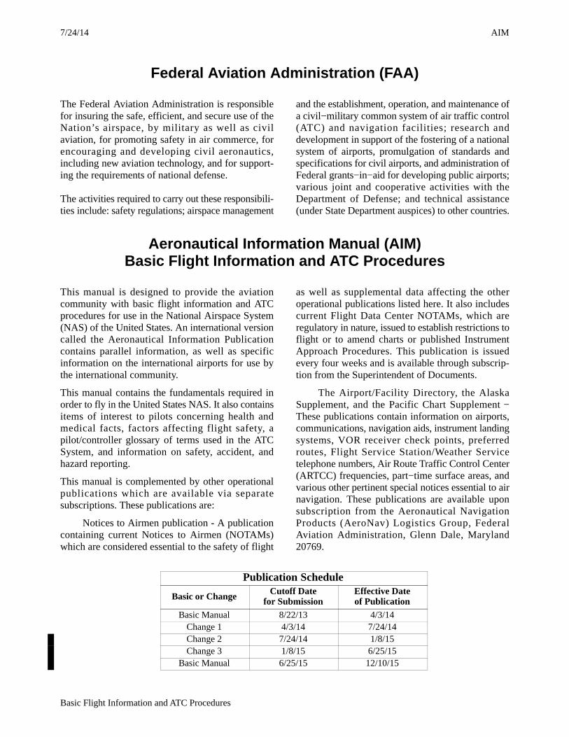
Federal Aviation Administration (FAA)
The Federal Aviation Administration is responsiblefor insuring the safe, efficient, and secure use of theNation’s airspace, by military as well as civilaviation, for promoting safety in air commerce, forencouraging and developing civil aeronautics,including new aviation technology, and for support-ing the requirements of national defense.
The activities required to carry out these responsibili-ties include: safety regulations; airspace management
and the establishment, operation, and maintenance ofa civil−military common system of air traffic control(ATC) and navigation facilities; research anddevelopment in support of the fostering of a nationalsystem of airports, promulgation of standards andspecifications for civil airports, and administration ofFederal grants−in−aid for developing public airports;various joint and cooperative activities with theDepartment of Defense; and technical assistance(under State Department auspices) to other countries.
Aeronautical Information Manual (AIM)Basic Flight Information and ATC Procedures
This manual is designed to provide the aviationcommunity with basic flight information and ATCprocedures for use in the National Airspace System(NAS) of the United States. An international versioncalled the Aeronautical Information Publicationcontains parallel information, as well as specificinformation on the international airports for use bythe international community.
This manual contains the fundamentals required inorder to fly in the United States NAS. It also containsitems of interest to pilots concerning health andmedical facts, factors affecting flight safety, apilot/controller glossary of terms used in the ATCSystem, and information on safety, accident, andhazard reporting.
This manual is complemented by other operationalpublications which are available via separatesubscriptions. These publications are:
Notices to Airmen publication - A publicationcontaining current Notices to Airmen (NOTAMs)which are considered essential to the safety of flight
as well as supplemental data affecting the otheroperational publications listed here. It also includescurrent Flight Data Center NOTAMs, which areregulatory in nature, issued to establish restrictions toflight or to amend charts or published InstrumentApproach Procedures. This publication is issuedevery four weeks and is available through subscrip-tion from the Superintendent of Documents.
The Airport/Facility Directory, the AlaskaSupplement, and the Pacific Chart Supplement −These publications contain information on airports,communications, navigation aids, instrument landingsystems, VOR receiver check points, preferredroutes, Flight Service Station/Weather Servicetelephone numbers, Air Route Traffic Control Center(ARTCC) frequencies, part−time surface areas, andvarious other pertinent special notices essential to airnavigation. These publications are available uponsubscription from the Aeronautical NavigationProducts (AeroNav) Logistics Group, FederalAviation Administration, Glenn Dale, Maryland20769.
Publication Schedule
Basic or Change Cutoff Datefor Submission
Effective Dateof Publication
Basic Manual 8/22/13 4/3/14Change 1 4/3/14 7/24/14Change 2 7/24/14 1/8/15Change 3 1/8/15 6/25/15
Basic Manual 6/25/15 12/10/15


AIM7/24/14
iTable of Contents
Table of Contents
Chapter 1. Air Navigation
Section 1. Navigation Aids
Paragraph Page1-1-1. General 1-1-1. . . . . . . . . . . . . . . . . . . . . . . . . . . . . . . . . . . . . . . . . . . . . . . . . . . . . . . . . . . .
1-1-2. Nondirectional Radio Beacon (NDB) 1-1-1. . . . . . . . . . . . . . . . . . . . . . . . . . . . . . . . . .
1-1-3. VHF Omni-directional Range (VOR) 1-1-1. . . . . . . . . . . . . . . . . . . . . . . . . . . . . . . . .
1-1-4. VOR Receiver Check 1-1-2. . . . . . . . . . . . . . . . . . . . . . . . . . . . . . . . . . . . . . . . . . . . . . . .
1-1-5. Tactical Air Navigation (TACAN) 1-1-3. . . . . . . . . . . . . . . . . . . . . . . . . . . . . . . . . . . . . .
1-1-6. VHF Omni-directional Range/Tactical Air Navigation (VORTAC) 1-1-3. . . . . . . . .
1-1-7. Distance Measuring Equipment (DME) 1-1-3. . . . . . . . . . . . . . . . . . . . . . . . . . . . . . . .
1-1-8. Navigational Aid (NAVAID) Service Volumes 1-1-4. . . . . . . . . . . . . . . . . . . . . . . . . . .
1-1-9. Instrument Landing System (ILS) 1-1-7. . . . . . . . . . . . . . . . . . . . . . . . . . . . . . . . . . . . . .
1-1-10. Simplified Directional Facility (SDF) 1-1-12. . . . . . . . . . . . . . . . . . . . . . . . . . . . . . . . . .
1-1-11. Microwave Landing System (MLS) 1-1-14. . . . . . . . . . . . . . . . . . . . . . . . . . . . . . . . . . . .
1-1-12. NAVAID Identifier Removal During Maintenance 1-1-16. . . . . . . . . . . . . . . . . . . . . .
1-1-13. NAVAIDs with Voice 1-1-17. . . . . . . . . . . . . . . . . . . . . . . . . . . . . . . . . . . . . . . . . . . . . . .
1-1-14. User Reports Requested on NAVAID or Global Navigation Satellite System (GNSS) Performance or Interference 1-1-17. . . . . . . . . . . . . . . . . . . . . . . . . . . . . . .
1-1-15. LORAN 1-1-17. . .
1-1-16. Inertial Reference Unit (IRU), Inertial Navigation System (INS), and Attitude Heading Reference System (AHRS) 1-1-17. . . . . . . . . . . . . . . . . . . . . . . .
1-1-17. Doppler Radar 1-1-18. . . . . . . . . . . . . . . . . . . . . . . . . . . . . . . . . . . . . . . . . . . . . . . . . . . . .
1-1-18. Global Positioning System (GPS) 1-1-18. . . . . . . . . . . . . . . . . . . . . . . . . . . . . . . . . . . . .
1-1-19. Wide Area Augmentation System (WAAS) 1-1-31. . . . . . . . . . . . . . . . . . . . . . . . . . . . .
1-1-20. Ground Based Augmentation System (GBAS) Landing System (GLS) 1-1-36. . . . . .
1-1-21. Precision Approach Systems other than ILS and GLS 1-1-36. . . . . . . . . . . . . . . . . . . .
Section 2. Area Navigation (RNAV) and Required NavigationPerformance (RNP)
1-2-1. Area Navigation (RNAV) 1-2-1. . . . . . . . . . . . . . . . . . . . . . . . . . . . . . . . . . . . . . . . . . . .
1-2-2. Required Navigation Performance (RNP) 1-2-4. . . . . . . . . . . . . . . . . . . . . . . . . . . . . . .
1-2-3. Use of Suitable Area Navigation (RNAV) Systems on Conventional Procedures and Routes 1-2-5. . . . . . . . . . . . . . . . . . . . . . . . . . . . . . . . . . . . . . . . . . .
Chapter 2. Aeronautical Lighting and Other Airport Visual Aids
Section 1. Airport Lighting Aids
2-1-1. Approach Light Systems (ALS) 2-1-1. . . . . . . . . . . . . . . . . . . . . . . . . . . . . . . . . . . . . . . .
2-1-2. Visual Glideslope Indicators 2-1-1. . . . . . . . . . . . . . . . . . . . . . . . . . . . . . . . . . . . . . . . . .
2-1-3. Runway End Identifier Lights (REIL) 2-1-6. . . . . . . . . . . . . . . . . . . . . . . . . . . . . . . . . .
2-1-4. Runway Edge Light Systems 2-1-6. . . . . . . . . . . . . . . . . . . . . . . . . . . . . . . . . . . . . . . . . .
2-1-5. In-runway Lighting 2-1-6. . . . . . . . . . . . . . . . . . . . . . . . . . . . . . . . . . . . . . . . . . . . . . . . .
2-1-6. Runway Status Light (RWSL) System 2-1-7. . . . . . . . . . . . . . . . . . . . . . . . . . . . . . . . . . .
2-1-7. StandAlone Final Approach Runway Occupancy Signal (FAROS) 2-1-10. . . . . . . . . .
AIM 7/24/14
ii Table of Contents
Paragraph Page2-1-8. Control of Lighting Systems 2-1-11. . . . . . . . . . . . . . . . . . . . . . . . . . . . . . . . . . . . . . . . . . .
2-1-9. Pilot Control of Airport Lighting 2-1-11. . . . . . . . . . . . . . . . . . . . . . . . . . . . . . . . . . . . . .
2-1-10. Airport/Heliport Beacons 2-1-14. . . . . . . . . . . . . . . . . . . . . . . . . . . . . . . . . . . . . . . . . . . .
2-1-11. Taxiway Lights 2-1-15. . . . . . . . . . . . . . . . . . . . . . . . . . . . . . . . . . . . . . . . . . . . . . . . . . . . .
Section 2. Air Navigation and Obstruction Lighting
2-2-1. Aeronautical Light Beacons 2-2-1. . . . . . . . . . . . . . . . . . . . . . . . . . . . . . . . . . . . . . . . . . .
2-2-2. Code Beacons and Course Lights 2-2-1. . . . . . . . . . . . . . . . . . . . . . . . . . . . . . . . . . . . . .
2-2-3. Obstruction Lights 2-2-1. . . . . . . . . . . . . . . . . . . . . . . . . . . . . . . . . . . . . . . . . . . . . . . . . .
Section 3. Airport Marking Aids and Signs
2-3-1. General 2-3-1. . . . . . . . . . . . . . . . . . . . . . . . . . . . . . . . . . . . . . . . . . . . . . . . . . . . . . . . . . . .
2-3-2. Airport Pavement Markings 2-3-1. . . . . . . . . . . . . . . . . . . . . . . . . . . . . . . . . . . . . . . . . . .
2-3-3. Runway Markings 2-3-1. . . . . . . . . . . . . . . . . . . . . . . . . . . . . . . . . . . . . . . . . . . . . . . . . . .
2-3-4. Taxiway Markings 2-3-7. . . . . . . . . . . . . . . . . . . . . . . . . . . . . . . . . . . . . . . . . . . . . . . . . . .
2-3-5. Holding Position Markings 2-3-12. . . . . . . . . . . . . . . . . . . . . . . . . . . . . . . . . . . . . . . . . . . .
2-3-6. Other Markings 2-3-16. . . . . . . . . . . . . . . . . . . . . . . . . . . . . . . . . . . . . . . . . . . . . . . . . . . . .
2-3-7. Airport Signs 2-3-19. . . . . . . . . . . . . . . . . . . . . . . . . . . . . . . . . . . . . . . . . . . . . . . . . . . . . . .
2-3-8. Mandatory Instruction Signs 2-3-20. . . . . . . . . . . . . . . . . . . . . . . . . . . . . . . . . . . . . . . . . .
2-3-9. Location Signs 2-3-23. . . . . . . . . . . . . . . . . . . . . . . . . . . . . . . . . . . . . . . . . . . . . . . . . . . . . .
2-3-10. Direction Signs 2-3-25. . . . . . . . . . . . . . . . . . . . . . . . . . . . . . . . . . . . . . . . . . . . . . . . . . . .
2-3-11. Destination Signs 2-3-28. . . . . . . . . . . . . . . . . . . . . . . . . . . . . . . . . . . . . . . . . . . . . . . . . .
2-3-12. Information Signs 2-3-29. . . . . . . . . . . . . . . . . . . . . . . . . . . . . . . . . . . . . . . . . . . . . . . . . .
2-3-13. Runway Distance Remaining Signs 2-3-29. . . . . . . . . . . . . . . . . . . . . . . . . . . . . . . . . . . .
2-3-14. Aircraft Arresting Systems 2-3-30. . . . . . . . . . . . . . . . . . . . . . . . . . . . . . . . . . . . . . . . . . .
2-3-15. Security Identifications Display Area (Airport Ramp Area) 2-3-31. . . . . . . . . . . . . . .
Chapter 3. Airspace
Section 1. General
3-1-1. General 3-1-1. . . . . . . . . . . . . . . . . . . . . . . . . . . . . . . . . . . . . . . . . . . . . . . . . . . . . . . . . . . .
3-1-2. General Dimensions of Airspace Segments 3-1-1. . . . . . . . . . . . . . . . . . . . . . . . . . . . . .
3-1-3. Hierarchy of Overlapping Airspace Designations 3-1-1. . . . . . . . . . . . . . . . . . . . . . . . .
3-1-4. Basic VFR Weather Minimums 3-1-1. . . . . . . . . . . . . . . . . . . . . . . . . . . . . . . . . . . . . . . .
3-1-5. VFR Cruising Altitudes and Flight Levels 3-1-2. . . . . . . . . . . . . . . . . . . . . . . . . . . . . . .
Section 2. Controlled Airspace
3-2-1. General 3-2-1. . . . . . . . . . . . . . . . . . . . . . . . . . . . . . . . . . . . . . . . . . . . . . . . . . . . . . . . . . . .
3-2-2. Class A Airspace 3-2-2. . . . . . . . . . . . . . . . . . . . . . . . . . . . . . . . . . . . . . . . . . . . . . . . . . . .
3-2-3. Class B Airspace 3-2-2. . . . . . . . . . . . . . . . . . . . . . . . . . . . . . . . . . . . . . . . . . . . . . . . . . . .
3-2-4. Class C Airspace 3-2-4. . . . . . . . . . . . . . . . . . . . . . . . . . . . . . . . . . . . . . . . . . . . . . . . . . . .
3-2-5. Class D Airspace 3-2-8. . . . . . . . . . . . . . . . . . . . . . . . . . . . . . . . . . . . . . . . . . . . . . . . . . . .
3-2-6. Class E Airspace 3-2-9. . . . . . . . . . . . . . . . . . . . . . . . . . . . . . . . . . . . . . . . . . . . . . . . . . . .
Section 3. Class G Airspace
3-3-1. General 3-3-1. . . . . . . . . . . . . . . . . . . . . . . . . . . . . . . . . . . . . . . . . . . . . . . . . . . . . . . . . . . .
3-3-2. VFR Requirements 3-3-1. . . . . . . . . . . . . . . . . . . . . . . . . . . . . . . . . . . . . . . . . . . . . . . . . .
3-3-3. IFR Requirements 3-3-1. . . . . . . . . . . . . . . . . . . . . . . . . . . . . . . . . . . . . . . . . . . . . . . . . .
AIM7/24/14
iiiTable of Contents
Section 4. Special Use Airspace
Paragraph Page3-4-1. General 3-4-1. . . . . . . . . . . . . . . . . . . . . . . . . . . . . . . . . . . . . . . . . . . . . . . . . . . . . . . . . . . .
3-4-2. Prohibited Areas 3-4-1. . . . . . . . . . . . . . . . . . . . . . . . . . . . . . . . . . . . . . . . . . . . . . . . . . . .
3-4-3. Restricted Areas 3-4-1. . . . . . . . . . . . . . . . . . . . . . . . . . . . . . . . . . . . . . . . . . . . . . . . . . . .
3-4-4. Warning Areas 3-4-1. . . . . . . . . . . . . . . . . . . . . . . . . . . . . . . . . . . . . . . . . . . . . . . . . . . . . .
3-4-5. Military Operations Areas 3-4-2. . . . . . . . . . . . . . . . . . . . . . . . . . . . . . . . . . . . . . . . . . . .
3-4-6. Alert Areas 3-4-2. . . . . . . . . . . . . . . . . . . . . . . . . . . . . . . . . . . . . . . . . . . . . . . . . . . . . . . . .
3-4-7. Controlled Firing Areas 3-4-2. . . . . . . . . . . . . . . . . . . . . . . . . . . . . . . . . . . . . . . . . . . . . .
3-4-8. National Security Areas 3-4-2. . . . . . . . . . . . . . . . . . . . . . . . . . . . . . . . . . . . . . . . . . . . . .
Section 5. Other Airspace Areas
3-5-1. Airport Advisory/Information Services 3-5-1. . . . . . . . . . . . . . . . . . . . . . . . . . . . . . . . . .
3-5-2. Military Training Routes 3-5-1. . . . . . . . . . . . . . . . . . . . . . . . . . . . . . . . . . . . . . . . . . . . .
3-5-3. Temporary Flight Restrictions 3-5-2. . . . . . . . . . . . . . . . . . . . . . . . . . . . . . . . . . . . . . . . .
3-5-4. Parachute Jump Aircraft Operations 3-5-5. . . . . . . . . . . . . . . . . . . . . . . . . . . . . . . . . . .
3-5-5. Published VFR Routes 3-5-5. . . . . . . . . . . . . . . . . . . . . . . . . . . . . . . . . . . . . . . . . . . . . . .
3-5-6. Terminal Radar Service Area (TRSA) 3-5-9. . . . . . . . . . . . . . . . . . . . . . . . . . . . . . . . . .
Chapter 4. Air Traffic Control
Section 1. Services Available to Pilots
4-1-1. Air Route Traffic Control Centers 4-1-1. . . . . . . . . . . . . . . . . . . . . . . . . . . . . . . . . . . . .
4-1-2. Control Towers 4-1-1. . . . . . . . . . . . . . . . . . . . . . . . . . . . . . . . . . . . . . . . . . . . . . . . . . . . .
4-1-3. Flight Service Stations 4-1-1. . . . . . . . . . . . . . . . . . . . . . . . . . . . . . . . . . . . . . . . . . . . . . .
4-1-4. Recording and Monitoring 4-1-1. . . . . . . . . . . . . . . . . . . . . . . . . . . . . . . . . . . . . . . . . . . .
4-1-5. Communications Release of IFR Aircraft Landing at an Airport Without an Operating Control Tower 4-1-1. . . . . . . . . . . . . . . . . . . . . . . . . . . . . . . . . . . . . . .
4-1-6. Pilot Visits to Air Traffic Facilities 4-1-1. . . . . . . . . . . . . . . . . . . . . . . . . . . . . . . . . . . . .
4-1-7. Operation Take‐off and Operation Raincheck 4-1-2. . . . . . . . . . . . . . . . . . . . . . . . . . .
4-1-8. Approach Control Service for VFR Arriving Aircraft 4-1-2. . . . . . . . . . . . . . . . . . . . .
4-1-9. Traffic Advisory Practices at Airports Without Operating Control Towers 4-1-2. . . .
4-1-10. IFR Approaches/Ground Vehicle Operations 4-1-6. . . . . . . . . . . . . . . . . . . . . . . . . . .
4-1-11. Designated UNICOM/MULTICOM Frequencies 4-1-6. . . . . . . . . . . . . . . . . . . . . . .
4-1-12. Use of UNICOM for ATC Purposes 4-1-7. . . . . . . . . . . . . . . . . . . . . . . . . . . . . . . . . . .
4-1-13. Automatic Terminal Information Service (ATIS) 4-1-7. . . . . . . . . . . . . . . . . . . . . . . .
4-1-14. Automatic Flight Information Service (AFIS) - Alaska FSSs Only 4-1-8. . . . . . . . .
4-1-15. Radar Traffic Information Service 4-1-8. . . . . . . . . . . . . . . . . . . . . . . . . . . . . . . . . . . .
4-1-16. Safety Alert 4-1-10. . . . . . . . . . . . . . . . . . . . . . . . . . . . . . . . . . . . . . . . . . . . . . . . . . . . . . .
4-1-17. Radar Assistance to VFR Aircraft 4-1-11. . . . . . . . . . . . . . . . . . . . . . . . . . . . . . . . . . . .
4-1-18. Terminal Radar Services for VFR Aircraft 4-1-12. . . . . . . . . . . . . . . . . . . . . . . . . . . . .
4-1-19. Tower En Route Control (TEC) 4-1-14. . . . . . . . . . . . . . . . . . . . . . . . . . . . . . . . . . . . . .
4-1-20. Transponder Operation 4-1-15. . . . . . . . . . . . . . . . . . . . . . . . . . . . . . . . . . . . . . . . . . . . .
4-1-21. Hazardous Area Reporting Service 4-1-18. . . . . . . . . . . . . . . . . . . . . . . . . . . . . . . . . . . .
4-1-22. Airport Reservation Operations and Special Traffic Management Programs 4-1-21.
4-1-23. Requests for Waivers and Authorizations from Title 14, Code of Federal Regulations (14 CFR) 4-1-23. . . . . . . . . . . . . . . . . . . . . . . . . . . . . . . . . . . . . . . . . . . .
4-1-24. Weather System Processor 4-1-23. . . . . . . . . . . . . . . . . . . . . . . . . . . . . . . . . . . . . . . . . . .
AIM 7/24/14
iv Table of Contents
Section 2. Radio Communications Phraseology and Techniques
Paragraph Page
4-2-1. General 4-2-1. . . . . . . . . . . . . . . . . . . . . . . . . . . . . . . . . . . . . . . . . . . . . . . . . . . . . . . . . . . .
4-2-2. Radio Technique 4-2-1. . . . . . . . . . . . . . . . . . . . . . . . . . . . . . . . . . . . . . . . . . . . . . . . . . . .
4-2-3. Contact Procedures 4-2-1. . . . . . . . . . . . . . . . . . . . . . . . . . . . . . . . . . . . . . . . . . . . . . . . . .
4-2-4. Aircraft Call Signs 4-2-3. . . . . . . . . . . . . . . . . . . . . . . . . . . . . . . . . . . . . . . . . . . . . . . . . . .
4-2-5. Description of Interchange or Leased Aircraft 4-2-4. . . . . . . . . . . . . . . . . . . . . . . . . . .
4-2-6. Ground Station Call Signs 4-2-4. . . . . . . . . . . . . . . . . . . . . . . . . . . . . . . . . . . . . . . . . . . .
4-2-7. Phonetic Alphabet 4-2-5. . . . . . . . . . . . . . . . . . . . . . . . . . . . . . . . . . . . . . . . . . . . . . . . . . .
4-2-8. Figures 4-2-6. . . . . . . . . . . . . . . . . . . . . . . . . . . . . . . . . . . . . . . . . . . . . . . . . . . . . . . . . . . .
4-2-9. Altitudes and Flight Levels 4-2-6. . . . . . . . . . . . . . . . . . . . . . . . . . . . . . . . . . . . . . . . . . .
4-2-10. Directions 4-2-6. . . . . . . . . . . . . . . . . . . . . . . . . . . . . . . . . . . . . . . . . . . . . . . . . . . . . . . . .
4-2-11. Speeds 4-2-6. . . . . . . . . . . . . . . . . . . . . . . . . . . . . . . . . . . . . . . . . . . . . . . . . . . . . . . . . . . .
4-2-12. Time 4-2-6. . . . . . . . . . . . . . . . . . . . . . . . . . . . . . . . . . . . . . . . . . . . . . . . . . . . . . . . . . . . .
4-2-13. Communications with Tower when Aircraft Transmitter or Receiver or Both are Inoperative 4-2-7. . . . . . . . . . . . . . . . . . . . . . . . . . . . . . . . . . . . . . . . . . . . . . . . . .
4-2-14. Communications for VFR Flights 4-2-8. . . . . . . . . . . . . . . . . . . . . . . . . . . . . . . . . . . . .
Section 3. Airport Operations
4-3-1. General 4-3-1. . . . . . . . . . . . . . . . . . . . . . . . . . . . . . . . . . . . . . . . . . . . . . . . . . . . . . . . . . . .
4-3-2. Airports with an Operating Control Tower 4-3-1. . . . . . . . . . . . . . . . . . . . . . . . . . . . . .
4-3-3. Traffic Patterns 4-3-2. . . . . . . . . . . . . . . . . . . . . . . . . . . . . . . . . . . . . . . . . . . . . . . . . . . . .
4-3-4. Visual Indicators at Airports Without an Operating Control Tower 4-3-6. . . . . . . . . .
4-3-5. Unexpected Maneuvers in the Airport Traffic Pattern 4-3-7. . . . . . . . . . . . . . . . . . . . .
4-3-6. Use of Runways/Declared Distances 4-3-7. . . . . . . . . . . . . . . . . . . . . . . . . . . . . . . . . . . .
4-3-7. Low Level Wind Shear/Microburst Detection Systems 4-3-12. . . . . . . . . . . . . . . . . . . .
4-3-8. Braking Action Reports and Advisories 4-3-12. . . . . . . . . . . . . . . . . . . . . . . . . . . . . . . . .
4-3-9. Runway Friction Reports and Advisories 4-3-12. . . . . . . . . . . . . . . . . . . . . . . . . . . . . . . .
4-3-10. Intersection Takeoffs 4-3-13. . . . . . . . . . . . . . . . . . . . . . . . . . . . . . . . . . . . . . . . . . . . . . .
4-3-11. Pilot Responsibilities When Conducting Land and Hold Short Operations (LAHSO) 4-3-14. . . . . . . . . . . . . . . . . . . . . . . . . . . . . . . . . . . . . . . . . . . . . . . . . . . . . . .
4-3-12. Low Approach 4-3-16. . . . . . . . . . . . . . . . . . . . . . . . . . . . . . . . . . . . . . . . . . . . . . . . . . . . .
4-3-13. Traffic Control Light Signals 4-3-16. . . . . . . . . . . . . . . . . . . . . . . . . . . . . . . . . . . . . . . . .
4-3-14. Communications 4-3-17. . . . . . . . . . . . . . . . . . . . . . . . . . . . . . . . . . . . . . . . . . . . . . . . . . .
4-3-15. Gate Holding Due to Departure Delays 4-3-18. . . . . . . . . . . . . . . . . . . . . . . . . . . . . . .
4-3-16. VFR Flights in Terminal Areas 4-3-18. . . . . . . . . . . . . . . . . . . . . . . . . . . . . . . . . . . . . . .
4-3-17. VFR Helicopter Operations at Controlled Airports 4-3-18. . . . . . . . . . . . . . . . . . . . . .
4-3-18. Taxiing 4-3-20. . . . . . . . . . . . . . . . . . . . . . . . . . . . . . . . . . . . . . . . . . . . . . . . . . . . . . . . . . .
4-3-19. Taxi During Low Visibility 4-3-21. . . . . . . . . . . . . . . . . . . . . . . . . . . . . . . . . . . . . . . . . . .
4-3-20. Exiting the Runway After Landing 4-3-22. . . . . . . . . . . . . . . . . . . . . . . . . . . . . . . . . . . .
4-3-21. Practice Instrument Approaches 4-3-22. . . . . . . . . . . . . . . . . . . . . . . . . . . . . . . . . . . . . .
4-3-22. Option Approach 4-3-24. . . . . . . . . . . . . . . . . . . . . . . . . . . . . . . . . . . . . . . . . . . . . . . . . .
4-3-23. Use of Aircraft Lights 4-3-24. . . . . . . . . . . . . . . . . . . . . . . . . . . . . . . . . . . . . . . . . . . . . . .
4-3-24. Flight Inspection/`Flight Check' Aircraft in Terminal Areas 4-3-25. . . . . . . . . . . . . . .
4-3-25. Hand Signals 4-3-25. . . . . . . . . . . . . . . . . . . . . . . . . . . . . . . . . . . . . . . . . . . . . . . . . . . . . .
4-3-26. Operations at Uncontrolled Airports With Automated Surface Observing System (ASOS)/Automated Weather Sensor System(AWSS)/Automated Weather Observing System (AWOS) 4-3-29. . . . . . . . . . . . . . . . . . . . . .
AIM7/24/14
vTable of Contents
Section 4. ATC Clearances and Aircraft Separation
Paragraph Page
4-4-1. Clearance 4-4-1. . . . . . . . . . . . . . . . . . . . . . . . . . . . . . . . . . . . . . . . . . . . . . . . . . . . . . . . . .
4-4-2. Clearance Prefix 4-4-1. . . . . . . . . . . . . . . . . . . . . . . . . . . . . . . . . . . . . . . . . . . . . . . . . . . .
4-4-3. Clearance Items 4-4-1. . . . . . . . . . . . . . . . . . . . . . . . . . . . . . . . . . . . . . . . . . . . . . . . . . . . .
4-4-4. Amended Clearances 4-4-2. . . . . . . . . . . . . . . . . . . . . . . . . . . . . . . . . . . . . . . . . . . . . . . .
4-4-5. Coded Departure Route (CDR) 4-4-3. . . . . . . . . . . . . . . . . . . . . . . . . . . . . . . . . . . . . . .
4-4-6. Special VFR Clearances 4-4-3. . . . . . . . . . . . . . . . . . . . . . . . . . . . . . . . . . . . . . . . . . . . . .
4-4-7. Pilot Responsibility upon Clearance Issuance 4-4-4. . . . . . . . . . . . . . . . . . . . . . . . . . . .
4-4-8. IFR Clearance VFR-on-top 4-4-4. . . . . . . . . . . . . . . . . . . . . . . . . . . . . . . . . . . . . . . . .
4-4-9. VFR/IFR Flights 4-4-5. . . . . . . . . . . . . . . . . . . . . . . . . . . . . . . . . . . . . . . . . . . . . . . . . . . .
4-4-10. Adherence to Clearance 4-4-5. . . . . . . . . . . . . . . . . . . . . . . . . . . . . . . . . . . . . . . . . . . . .
4-4-11. IFR Separation Standards 4-4-7. . . . . . . . . . . . . . . . . . . . . . . . . . . . . . . . . . . . . . . . . . .
4-4-12. Speed Adjustments 4-4-7. . . . . . . . . . . . . . . . . . . . . . . . . . . . . . . . . . . . . . . . . . . . . . . . .
4-4-13. Runway Separation 4-4-9. . . . . . . . . . . . . . . . . . . . . . . . . . . . . . . . . . . . . . . . . . . . . . . . .
4-4-14. Visual Separation 4-4-10. . . . . . . . . . . . . . . . . . . . . . . . . . . . . . . . . . . . . . . . . . . . . . . . . .
4-4-15. Use of Visual Clearing Procedures 4-4-10. . . . . . . . . . . . . . . . . . . . . . . . . . . . . . . . . . . .
4-4-16. Traffic Alert and Collision Avoidance System (TCAS I & II) 4-4-11. . . . . . . . . . . . . .
4-4-17. Traffic Information Service (TIS) 4-4-11. . . . . . . . . . . . . . . . . . . . . . . . . . . . . . . . . . . . .
Section 5. Surveillance Systems
4-5-1. Radar 4-5-1. . . . . . . . . . . . . . . . . . . . . . . . . . . . . . . . . . . . . . . . . . . . . . . . . . . . . . . . . . . . .
4-5-2. Air Traffic Control Radar Beacon System (ATCRBS) 4-5-2. . . . . . . . . . . . . . . . . . . . .
4-5-3. Surveillance Radar 4-5-7. . . . . . . . . . . . . . . . . . . . . . . . . . . . . . . . . . . . . . . . . . . . . . . . . .
4-5-4. Precision Approach Radar (PAR) 4-5-7. . . . . . . . . . . . . . . . . . . . . . . . . . . . . . . . . . . . . .
4-5-5. Airport Surface Detection Equipment - Model X (ASDE-X) 4-5-7. . . . . . . . . . . .
4-5-6. Traffic Information Service (TIS) 4-5-8. . . . . . . . . . . . . . . . . . . . . . . . . . . . . . . . . . . . . .
4-5-7. Automatic Dependent Surveillance-Broadcast (ADS-B) Services 4-5-14. . . . . . . . .
4-5-8. Traffic Information Service- Broadcast (TIS-B) 4-5-17. . . . . . . . . . . . . . . . . . . . . . . .
4-5-9. Flight Information Service- Broadcast (FIS-B) 4-5-18. . . . . . . . . . . . . . . . . . . . . . . . .
4-5-10. Automatic Dependent Surveillance-Rebroadcast (ADS-R) 4-5-20. . . . . . . . . . . . . .
Section 6. Operational Policy/Procedures for Reduced VerticalSeparation Minimum (RVSM) in the Domestic U.S., Alaska, Offshore
Airspace and the San Juan FIR
4-6-1. Applicability and RVSM Mandate (Date/Time and Area) 4-6-1. . . . . . . . . . . . . . . . .
4-6-2. Flight Level Orientation Scheme 4-6-1. . . . . . . . . . . . . . . . . . . . . . . . . . . . . . . . . . . . . .
4-6-3. Aircraft and Operator Approval Policy/Procedures, RVSM Monitoring and Databases for Aircraft and Operator Approval 4-6-2. . . . . . . . . . . . . . . . . . . . . . .
4-6-4. Flight Planning into RVSM Airspace 4-6-3. . . . . . . . . . . . . . . . . . . . . . . . . . . . . . . . . . .
4-6-5. Pilot RVSM Operating Practices and Procedures 4-6-3. . . . . . . . . . . . . . . . . . . . . . . . .
4-6-6. Guidance on Severe Turbulence and Mountain Wave Activity (MWA) 4-6-4. . . . . . .
4-6-7. Guidance on Wake Turbulence 4-6-5. . . . . . . . . . . . . . . . . . . . . . . . . . . . . . . . . . . . . . . .
4-6-8. Pilot/Controller Phraseology 4-6-6. . . . . . . . . . . . . . . . . . . . . . . . . . . . . . . . . . . . . . . . . .
4-6-9. Contingency Actions: Weather Encounters and Aircraft System Failures that Occur After Entry into RVSM Airspace 4-6-8. . . . . . . . . . . . . . . . . . . . . . . . . . . . .
4-6-10. Procedures for Accommodation of Non-RVSM Aircraft 4-6-10. . . . . . . . . . . . . . . . .
4-6-11. Non-RVSM Aircraft Requesting Climb to and Descent from Flight Levels Above RVSM Airspace Without Intermediate Level Off 4-6-11. . . . . . . . . . . . . . .
AIM 7/24/14
vi Table of Contents
Section 7. Operational Policy/Procedures for the Gulf of Mexico 50 NMLateral Separation Initiative
Paragraph Page
4-7-1. Introduction and Background 4-7-1. . . . . . . . . . . . . . . . . . . . . . . . . . . . . . . . . . . . . . . . .
4-7-2. Gulf of Mexico 50 NM Lateral Separation Initiative Web Page: Policy, Procedures and Guidance for Operators and Regulators 4-7-1. . . . . . . . . . . . . . . . . . . . . . . . .
4-7-3. Lateral Separation Minima Applied 4-7-1. . . . . . . . . . . . . . . . . . . . . . . . . . . . . . . . . . . .
4-7-4. Operation on Routes on the periphery of the Gulf of Mexico CTAs 4-7-2. . . . . . . . .
4-7-5. Provisions for Accommodation of NonRNP10 Aircraft (Aircraft Not Authorized RNP 10 or RNP 4) 4-7-2. . . . . . . . . . . . . . . . . . . . . . . . . . . . . . . . . . . . . . . . . . . . . . .
4-7-6. Operator Action 4-7-2. . . . . . . . . . . . . . . . . . . . . . . . . . . . . . . . . . . . . . . . . . . . . . . . . . . .
4-7-7. RNP 10 or RNP 4 Authorization: Policy and Procedures for Aircraft and Operators 4-7-2. . . . . . . . . . . . . . . . . . . . . . . . . . . . . . . . . . . . . . . . . . . . . . . . . . . . . .
4-7-8. Flight Planning Requirements 4-7-4. . . . . . . . . . . . . . . . . . . . . . . . . . . . . . . . . . . . . . . . .
4-7-9. Pilot and Dispatcher Procedures: Basic and Inflight Contingency Procedures 4-7-5.
Chapter 5. Air Traffic Procedures
Section 1. Preflight
5-1-1. Preflight Preparation 5-1-1. . . . . . . . . . . . . . . . . . . . . . . . . . . . . . . . . . . . . . . . . . . . . . . .
5-1-2. Follow IFR Procedures Even When Operating VFR 5-1-2. . . . . . . . . . . . . . . . . . . . . .
5-1-3. Notice to Airmen (NOTAM) System 5-1-2. . . . . . . . . . . . . . . . . . . . . . . . . . . . . . . . . . .
5-1-4. Flight Plan - VFR Flights 5-1-7. . . . . . . . . . . . . . . . . . . . . . . . . . . . . . . . . . . . . . . . . . . .
5-1-5. Operational Information System (OIS) 5-1-10. . . . . . . . . . . . . . . . . . . . . . . . . . . . . . . . .
5-1-6. Flight Plan- Defense VFR (DVFR) Flights 5-1-10. . . . . . . . . . . . . . . . . . . . . . . . . . . . .
5-1-7. Composite Flight Plan (VFR/IFR Flights) 5-1-11. . . . . . . . . . . . . . . . . . . . . . . . . . . . . . .
5-1-8. Flight Plan (FAA Form 7233-1)- Domestic IFR Flights 5-1-11. . . . . . . . . . . . . . . . . .
5-1-9. International Flight Plan (FAA Form 7233-4)- IFR Flights (For Domestic or International Flights) 5-1-17. . . . . . . . . . . . . . . . . . . . . . . . . . . . . . . . . . . . . . . . . .
5-1-10. IFR Operations to High Altitude Destinations 5-1-27. . . . . . . . . . . . . . . . . . . . . . . . . .
5-1-11. Flights Outside the U.S. and U.S. Territories 5-1-28. . . . . . . . . . . . . . . . . . . . . . . . . . .
5-1-12. Change in Flight Plan 5-1-30. . . . . . . . . . . . . . . . . . . . . . . . . . . . . . . . . . . . . . . . . . . . . . .
5-1-13. Change in Proposed Departure Time 5-1-30. . . . . . . . . . . . . . . . . . . . . . . . . . . . . . . . . .
5-1-14. Closing VFR/DVFR Flight Plans 5-1-30. . . . . . . . . . . . . . . . . . . . . . . . . . . . . . . . . . . . .
5-1-15. Canceling IFR Flight Plan 5-1-30. . . . . . . . . . . . . . . . . . . . . . . . . . . . . . . . . . . . . . . . . . .
5-1-16. RNAV and RNP Operations 5-1-30. . . . . . . . . . . . . . . . . . . . . . . . . . . . . . . . . . . . . . . . .
Section 2. Departure Procedures
5-2-1. Pre‐taxi Clearance Procedures 5-2-1. . . . . . . . . . . . . . . . . . . . . . . . . . . . . . . . . . . . . . . . .
5-2-2. Pre-departure Clearance Procedures 5-2-1. . . . . . . . . . . . . . . . . . . . . . . . . . . . . . . . . .
5-2-3. Taxi Clearance 5-2-1. . . . . . . . . . . . . . . . . . . . . . . . . . . . . . . . . . . . . . . . . . . . . . . . . . . . . .
5-2-4. Line Up and Wait (LUAW) 5-2-1. . . . . . . . . . . . . . . . . . . . . . . . . . . . . . . . . . . . . . . . . . .
5-2-5. Abbreviated IFR Departure Clearance (Cleared. . .as Filed) Procedures 5-2-2. . . . .
5-2-6. Departure Restrictions, Clearance Void Times, Hold for Release, and Release Times 5-2-4. . . . . . . . . . . . . . . . . . . . . . . . . . . . . . . . . . . . . . . . . . . . . . . . . . .
5-2-7. Departure Control 5-2-5. . . . . . . . . . . . . . . . . . . . . . . . . . . . . . . . . . . . . . . . . . . . . . . . . .
5-2-8. Instrument Departure Procedures (DP) - Obstacle Departure Procedures (ODP) and Standard Instrument Departures (SID) 5-2-5. . . . . . . . . . . . . . . . . . .
AIM7/24/14
viiTable of Contents
Section 3. En Route Procedures
Paragraph Page5-3-1. ARTCC Communications 5-3-1. . . . . . . . . . . . . . . . . . . . . . . . . . . . . . . . . . . . . . . . . . . .
5-3-2. Position Reporting 5-3-3. . . . . . . . . . . . . . . . . . . . . . . . . . . . . . . . . . . . . . . . . . . . . . . . . .
5-3-3. Additional Reports 5-3-4. . . . . . . . . . . . . . . . . . . . . . . . . . . . . . . . . . . . . . . . . . . . . . . . . .
5-3-4. Airways and Route Systems 5-3-5. . . . . . . . . . . . . . . . . . . . . . . . . . . . . . . . . . . . . . . . . . .
5-3-5. Airway or Route Course Changes 5-3-7. . . . . . . . . . . . . . . . . . . . . . . . . . . . . . . . . . . . . .
5-3-6. Changeover Points (COPs) 5-3-8. . . . . . . . . . . . . . . . . . . . . . . . . . . . . . . . . . . . . . . . . . .
5-3-7. Minimum Turning Altitude (MTA) 5-3-8. . . . . . . . . . . . . . . . . . . . . . . . . . . . . . . . . . . . .
5-3-8. Holding 5-3-8. . . . . . . . . . . . . . . . . . . . . . . . . . . . . . . . . . . . . . . . . . . . . . . . . . . . . . . . . . . .
Section 4. Arrival Procedures
5-4-1. Standard Terminal Arrival (STAR) Procedures 5-4-1. . . . . . . . . . . . . . . . . . . . . . . . . . .
5-4-2. Local Flow Traffic Management Program 5-4-3. . . . . . . . . . . . . . . . . . . . . . . . . . . . . . .
5-4-3. Approach Control 5-4-3. . . . . . . . . . . . . . . . . . . . . . . . . . . . . . . . . . . . . . . . . . . . . . . . . . .
5-4-4. Advance Information on Instrument Approach 5-4-4. . . . . . . . . . . . . . . . . . . . . . . . . .
5-4-5. Instrument Approach Procedure Charts 5-4-5. . . . . . . . . . . . . . . . . . . . . . . . . . . . . . . .
5-4-6. Approach Clearance 5-4-24. . . . . . . . . . . . . . . . . . . . . . . . . . . . . . . . . . . . . . . . . . . . . . . . .
5-4-7. Instrument Approach Procedures 5-4-26. . . . . . . . . . . . . . . . . . . . . . . . . . . . . . . . . . . . . .
5-4-8. Special Instrument Approach Procedures 5-4-27. . . . . . . . . . . . . . . . . . . . . . . . . . . . . . .
5-4-9. Procedure Turn and Hold-in-lieu of Procedure Turn 5-4-28. . . . . . . . . . . . . . . . . . . .
5-4-10. Timed Approaches from a Holding Fix 5-4-31. . . . . . . . . . . . . . . . . . . . . . . . . . . . . . . .
5-4-11. Radar Approaches 5-4-34. . . . . . . . . . . . . . . . . . . . . . . . . . . . . . . . . . . . . . . . . . . . . . . . .
5-4-12. Radar Monitoring of Instrument Approaches 5-4-35. . . . . . . . . . . . . . . . . . . . . . . . . . .
5-4-13. ILS/RNAV/GLS Approaches to Parallel Runways 5-4-36. . . . . . . . . . . . . . . . . . . . . . .
5-4-14. Simultaneous (Parallel) Dependent ILS/RNAV/GLS Approaches(See FIG 5-4-19.) 5-4-38. . . . . . . . . . . . . . . . . . . . . . . . . . . . . . . . . . . . . . . . . . . . . .
5-4-15. Simultaneous (Parallel) Independent ILS/RNAV/GLS Approaches(See FIG 5-4-20.) 5-4-40. . . . . . . . . . . . . . . . . . . . . . . . . . . . . . . . . . . . . . . . . . . . . .
5-4-16. Simultaneous Close Parallel ILS PRM/RNAV PRM/GLS PRM Approaches and Simultaneous Offset Instrument Approaches (SOIA)(See FIG 5-4-21.) 5-4-42. . . . . . . . . . . . . . . . . . . . . . . . . . . . . . . . . . . . . . . . . . . . . .
5-4-17. Simultaneous Converging Instrument Approaches 5-4-49. . . . . . . . . . . . . . . . . . . . . . .
5-4-18. RNP AR Instrument Approach Procedures 5-4-49. . . . . . . . . . . . . . . . . . . . . . . . . . . . .
5-4-19. Side-step Maneuver 5-4-52. . . . . . . . . . . . . . . . . . . . . . . . . . . . . . . . . . . . . . . . . . . . . . .
5-4-20. Approach and Landing Minimums 5-4-52. . . . . . . . . . . . . . . . . . . . . . . . . . . . . . . . . . . .
5-4-21. Missed Approach 5-4-55. . . . . . . . . . . . . . . . . . . . . . . . . . . . . . . . . . . . . . . . . . . . . . . . . .
5-4-22. Use of Enhanced Flight Vision Systems (EFVS) on Instrument Approaches 5-4-58.
5-4-23. Visual Approach 5-4-60. . . . . . . . . . . . . . . . . . . . . . . . . . . . . . . . . . . . . . . . . . . . . . . . . . .
5-4-24. Charted Visual Flight Procedure (CVFP) 5-4-61. . . . . . . . . . . . . . . . . . . . . . . . . . . . . .
5-4-25. Contact Approach 5-4-62. . . . . . . . . . . . . . . . . . . . . . . . . . . . . . . . . . . . . . . . . . . . . . . . . .
5-4-26. Landing Priority 5-4-62. . . . . . . . . . . . . . . . . . . . . . . . . . . . . . . . . . . . . . . . . . . . . . . . . . .
5-4-27. Overhead Approach Maneuver 5-4-62. . . . . . . . . . . . . . . . . . . . . . . . . . . . . . . . . . . . . . .
Section 5. Pilot/Controller Roles and Responsibilities
5-5-1. General 5-5-1. . . . . . . . . . . . . . . . . . . . . . . . . . . . . . . . . . . . . . . . . . . . . . . . . . . . . . . . . . . .
5-5-2. Air Traffic Clearance 5-5-1. . . . . . . . . . . . . . . . . . . . . . . . . . . . . . . . . . . . . . . . . . . . . . . .
5-5-3. Contact Approach 5-5-2. . . . . . . . . . . . . . . . . . . . . . . . . . . . . . . . . . . . . . . . . . . . . . . . . . .
5-5-4. Instrument Approach 5-5-2. . . . . . . . . . . . . . . . . . . . . . . . . . . . . . . . . . . . . . . . . . . . . . . .
5-5-5. Missed Approach 5-5-2. . . . . . . . . . . . . . . . . . . . . . . . . . . . . . . . . . . . . . . . . . . . . . . . . . .
5-5-6. Radar Vectors 5-5-3. . . . . . . . . . . . . . . . . . . . . . . . . . . . . . . . . . . . . . . . . . . . . . . . . . . . . .
AIM 7/24/14
viii Table of Contents
Paragraph Page5-5-7. Safety Alert 5-5-3. . . . . . . . . . . . . . . . . . . . . . . . . . . . . . . . . . . . . . . . . . . . . . . . . . . . . . . .
5-5-8. See and Avoid 5-5-4. . . . . . . . . . . . . . . . . . . . . . . . . . . . . . . . . . . . . . . . . . . . . . . . . . . . . .
5-5-9. Speed Adjustments 5-5-4. . . . . . . . . . . . . . . . . . . . . . . . . . . . . . . . . . . . . . . . . . . . . . . . . .
5-5-10. Traffic Advisories (Traffic Information) 5-5-4. . . . . . . . . . . . . . . . . . . . . . . . . . . . . . . .
5-5-11. Visual Approach 5-5-5. . . . . . . . . . . . . . . . . . . . . . . . . . . . . . . . . . . . . . . . . . . . . . . . . . .
5-5-12. Visual Separation 5-5-5. . . . . . . . . . . . . . . . . . . . . . . . . . . . . . . . . . . . . . . . . . . . . . . . . .
5-5-13. VFR‐on‐top 5-5-6. . . . . . . . . . . . . . . . . . . . . . . . . . . . . . . . . . . . . . . . . . . . . . . . . . . . . . .
5-5-14. Instrument Departures 5-5-6. . . . . . . . . . . . . . . . . . . . . . . . . . . . . . . . . . . . . . . . . . . . . .
5-5-15. Minimum Fuel Advisory 5-5-7. . . . . . . . . . . . . . . . . . . . . . . . . . . . . . . . . . . . . . . . . . . . .
5-5-16. RNAV and RNP Operations 5-5-7. . . . . . . . . . . . . . . . . . . . . . . . . . . . . . . . . . . . . . . . .
Section 6. National Security and Interception Procedures
5-6-1. National Security 5-6-1. . . . . . . . . . . . . . . . . . . . . . . . . . . . . . . . . . . . . . . . . . . . . . . . . . . .
5-6-2. Interception Procedures 5-6-2. . . . . . . . . . . . . . . . . . . . . . . . . . . . . . . . . . . . . . . . . . . . . .
5-6-3. Law Enforcement Operations by Civil and Military Organizations 5-6-6. . . . . . . . . .
5-6-4. Interception Signals 5-6-7. . . . . . . . . . . . . . . . . . . . . . . . . . . . . . . . . . . . . . . . . . . . . . . . .
5-6-5. ADIZ Boundaries and Designated Mountainous Areas (See FIG 5-6-3.) 5-6-9. . .
5-6-6. Visual Warning System (VWS) 5-6-10. . . . . . . . . . . . . . . . . . . . . . . . . . . . . . . . . . . . . . . .
Chapter 6. Emergency Procedures
Section 1. General
6-1-1. Pilot Responsibility and Authority 6-1-1. . . . . . . . . . . . . . . . . . . . . . . . . . . . . . . . . . . . .
6-1-2. Emergency Condition- Request Assistance Immediately 6-1-1. . . . . . . . . . . . . . . . . .
Section 2. Emergency Services Available to Pilots
6-2-1. Radar Service for VFR Aircraft in Difficulty 6-2-1. . . . . . . . . . . . . . . . . . . . . . . . . . . .
6-2-2. Transponder Emergency Operation 6-2-1. . . . . . . . . . . . . . . . . . . . . . . . . . . . . . . . . . . .
6-2-3. Intercept and Escort 6-2-1. . . . . . . . . . . . . . . . . . . . . . . . . . . . . . . . . . . . . . . . . . . . . . . . .
6-2-4. Emergency Locator Transmitter (ELT) 6-2-2. . . . . . . . . . . . . . . . . . . . . . . . . . . . . . . . .
6-2-5. FAA K-9 Explosives Detection Team Program 6-2-3. . . . . . . . . . . . . . . . . . . . . . . . . .
6-2-6. Search and Rescue 6-2-4. . . . . . . . . . . . . . . . . . . . . . . . . . . . . . . . . . . . . . . . . . . . . . . . . .
Section 3. Distress and Urgency Procedures
6-3-1. Distress and Urgency Communications 6-3-1. . . . . . . . . . . . . . . . . . . . . . . . . . . . . . . . .
6-3-2. Obtaining Emergency Assistance 6-3-2. . . . . . . . . . . . . . . . . . . . . . . . . . . . . . . . . . . . . .
6-3-3. Ditching Procedures 6-3-3. . . . . . . . . . . . . . . . . . . . . . . . . . . . . . . . . . . . . . . . . . . . . . . . .
6-3-4. Special Emergency (Air Piracy) 6-3-6. . . . . . . . . . . . . . . . . . . . . . . . . . . . . . . . . . . . . . . .
6-3-5. Fuel Dumping 6-3-7. . . . . . . . . . . . . . . . . . . . . . . . . . . . . . . . . . . . . . . . . . . . . . . . . . . . . .
Section 4. Two‐way Radio Communications Failure
6-4-1. Two‐way Radio Communications Failure 6-4-1. . . . . . . . . . . . . . . . . . . . . . . . . . . . . . . .
6-4-2. Transponder Operation During Two‐way Communications Failure 6-4-2. . . . . . . . . .
6-4-3. Reestablishing Radio Contact 6-4-2. . . . . . . . . . . . . . . . . . . . . . . . . . . . . . . . . . . . . . . . .
AIM7/24/14
ixTable of Contents
Section 5. Aircraft Rescue and Fire Fighting Communications
Paragraph Page
6-5-1. Discrete Emergency Frequency 6-5-1. . . . . . . . . . . . . . . . . . . . . . . . . . . . . . . . . . . . . . . .
6-5-2. Radio Call Signs 6-5-1. . . . . . . . . . . . . . . . . . . . . . . . . . . . . . . . . . . . . . . . . . . . . . . . . . . .
6-5-3. ARFF Emergency Hand Signals 6-5-1. . . . . . . . . . . . . . . . . . . . . . . . . . . . . . . . . . . . . . .
Chapter 7. Safety of Flight
Section 1. Meteorology
7-1-1. National Weather Service Aviation Products 7-1-1. . . . . . . . . . . . . . . . . . . . . . . . . . . . .
7-1-2. FAA Weather Services 7-1-1. . . . . . . . . . . . . . . . . . . . . . . . . . . . . . . . . . . . . . . . . . . . . . .
7-1-3. Use of Aviation Weather Products 7-1-3. . . . . . . . . . . . . . . . . . . . . . . . . . . . . . . . . . . . .
7-1-4. Preflight Briefing 7-1-5. . . . . . . . . . . . . . . . . . . . . . . . . . . . . . . . . . . . . . . . . . . . . . . . . . . .
7-1-5. En Route Flight Advisory Service (EFAS) 7-1-7. . . . . . . . . . . . . . . . . . . . . . . . . . . . . . .
7-1-6. Inflight Aviation Weather Advisories 7-1-8. . . . . . . . . . . . . . . . . . . . . . . . . . . . . . . . . . .
7-1-7. Categorical Outlooks 7-1-18. . . . . . . . . . . . . . . . . . . . . . . . . . . . . . . . . . . . . . . . . . . . . . . .
7-1-8. Telephone Information Briefing Service (TIBS) 7-1-19. . . . . . . . . . . . . . . . . . . . . . . . . .
7-1-9. Transcribed Weather Broadcast (TWEB) (Alaska Only) 7-1-19. . . . . . . . . . . . . . . . . . .
7-1-10. Inflight Weather Broadcasts 7-1-19. . . . . . . . . . . . . . . . . . . . . . . . . . . . . . . . . . . . . . . . .
7-1-11. Flight Information Services (FIS) 7-1-22. . . . . . . . . . . . . . . . . . . . . . . . . . . . . . . . . . . . .
7-1-12. Weather Observing Programs 7-1-26. . . . . . . . . . . . . . . . . . . . . . . . . . . . . . . . . . . . . . . .
7-1-13. Weather Radar Services 7-1-34. . . . . . . . . . . . . . . . . . . . . . . . . . . . . . . . . . . . . . . . . . . . .
7-1-14. ATC Inflight Weather Avoidance Assistance 7-1-38. . . . . . . . . . . . . . . . . . . . . . . . . . . .
7-1-15. Runway Visual Range (RVR) 7-1-40. . . . . . . . . . . . . . . . . . . . . . . . . . . . . . . . . . . . . . . .
7-1-16. Reporting of Cloud Heights 7-1-42. . . . . . . . . . . . . . . . . . . . . . . . . . . . . . . . . . . . . . . . . .
7-1-17. Reporting Prevailing Visibility 7-1-42. . . . . . . . . . . . . . . . . . . . . . . . . . . . . . . . . . . . . . . .
7-1-18. Estimating Intensity of Rain and Ice Pellets 7-1-42. . . . . . . . . . . . . . . . . . . . . . . . . . . .
7-1-19. Estimating Intensity of Snow or Drizzle (Based on Visibility) 7-1-43. . . . . . . . . . . . . .
7-1-20. Pilot Weather Reports (PIREPs) 7-1-43. . . . . . . . . . . . . . . . . . . . . . . . . . . . . . . . . . . . . .
7-1-21. PIREPs Relating to Airframe Icing 7-1-44. . . . . . . . . . . . . . . . . . . . . . . . . . . . . . . . . . . .
7-1-22. Definitions of Inflight Icing Terms 7-1-45. . . . . . . . . . . . . . . . . . . . . . . . . . . . . . . . . . . .
7-1-23. PIREPs Relating to Turbulence 7-1-47. . . . . . . . . . . . . . . . . . . . . . . . . . . . . . . . . . . . . . .
7-1-24. Wind Shear PIREPs 7-1-48. . . . . . . . . . . . . . . . . . . . . . . . . . . . . . . . . . . . . . . . . . . . . . . .
7-1-25. Clear Air Turbulence (CAT) PIREPs 7-1-48. . . . . . . . . . . . . . . . . . . . . . . . . . . . . . . . . .
7-1-26. Microbursts 7-1-48. . . . . . . . . . . . . . . . . . . . . . . . . . . . . . . . . . . . . . . . . . . . . . . . . . . . . . .
7-1-27. PIREPs Relating to Volcanic Ash Activity 7-1-58. . . . . . . . . . . . . . . . . . . . . . . . . . . . . .
7-1-28. Thunderstorms 7-1-58. . . . . . . . . . . . . . . . . . . . . . . . . . . . . . . . . . . . . . . . . . . . . . . . . . . .
7-1-29. Thunderstorm Flying 7-1-59. . . . . . . . . . . . . . . . . . . . . . . . . . . . . . . . . . . . . . . . . . . . . . .
7-1-30. Key to Aerodrome Forecast (TAF) and Aviation Routine Weather Report (METAR) 7-1-61. . . . . . . . . . . . . . . . . . . . . . . . . . . . . . . . . . . . . . . . . . . . . . . .
7-1-31. International Civil Aviation Organization (ICAO) Weather Formats 7-1-63. . . . . . .
Section 2. Altimeter Setting Procedures
7-2-1. General 7-2-1. . . . . . . . . . . . . . . . . . . . . . . . . . . . . . . . . . . . . . . . . . . . . . . . . . . . . . . . . . . .
7-2-2. Procedures 7-2-1. . . . . . . . . . . . . . . . . . . . . . . . . . . . . . . . . . . . . . . . . . . . . . . . . . . . . . . . .
7-2-3. Altimeter Errors 7-2-3. . . . . . . . . . . . . . . . . . . . . . . . . . . . . . . . . . . . . . . . . . . . . . . . . . . .
7-2-4. High Barometric Pressure 7-2-4. . . . . . . . . . . . . . . . . . . . . . . . . . . . . . . . . . . . . . . . . . . .
7-2-5. Low Barometric Pressure 7-2-4. . . . . . . . . . . . . . . . . . . . . . . . . . . . . . . . . . . . . . . . . . . . .
AIM 7/24/14
x Table of Contents
Section 3. Wake Turbulence
Paragraph Page7-3-1. General 7-3-1. . . . . . . . . . . . . . . . . . . . . . . . . . . . . . . . . . . . . . . . . . . . . . . . . . . . . . . . . . . .
7-3-2. Vortex Generation 7-3-1. . . . . . . . . . . . . . . . . . . . . . . . . . . . . . . . . . . . . . . . . . . . . . . . . .
7-3-3. Vortex Strength 7-3-1. . . . . . . . . . . . . . . . . . . . . . . . . . . . . . . . . . . . . . . . . . . . . . . . . . . . .
7-3-4. Vortex Behavior 7-3-2. . . . . . . . . . . . . . . . . . . . . . . . . . . . . . . . . . . . . . . . . . . . . . . . . . . . .
7-3-5. Operations Problem Areas 7-3-5. . . . . . . . . . . . . . . . . . . . . . . . . . . . . . . . . . . . . . . . . . . .
7-3-6. Vortex Avoidance Procedures 7-3-5. . . . . . . . . . . . . . . . . . . . . . . . . . . . . . . . . . . . . . . . .
7-3-7. Helicopters 7-3-6. . . . . . . . . . . . . . . . . . . . . . . . . . . . . . . . . . . . . . . . . . . . . . . . . . . . . . . . .
7-3-8. Pilot Responsibility 7-3-6. . . . . . . . . . . . . . . . . . . . . . . . . . . . . . . . . . . . . . . . . . . . . . . . . .
7-3-9. Air Traffic Wake Turbulence Separations 7-3-7. . . . . . . . . . . . . . . . . . . . . . . . . . . . . . . .
Section 4. Bird Hazards and Flight Over National Refuges, Parks, andForests
7-4-1. Migratory Bird Activity 7-4-1. . . . . . . . . . . . . . . . . . . . . . . . . . . . . . . . . . . . . . . . . . . . . .
7-4-2. Reducing Bird Strike Risks 7-4-1. . . . . . . . . . . . . . . . . . . . . . . . . . . . . . . . . . . . . . . . . . .
7-4-3. Reporting Bird Strikes 7-4-1. . . . . . . . . . . . . . . . . . . . . . . . . . . . . . . . . . . . . . . . . . . . . . .
7-4-4. Reporting Bird and Other Wildlife Activities 7-4-1. . . . . . . . . . . . . . . . . . . . . . . . . . . .
7-4-5. Pilot Advisories on Bird and Other Wildlife Hazards 7-4-2. . . . . . . . . . . . . . . . . . . . . .
7-4-6. Flights Over Charted U.S. Wildlife Refuges, Parks, and Forest Service Areas 7-4-2.
Section 5. Potential Flight Hazards
7-5-1. Accident Cause Factors 7-5-1. . . . . . . . . . . . . . . . . . . . . . . . . . . . . . . . . . . . . . . . . . . . . .
7-5-2. VFR in Congested Areas 7-5-1. . . . . . . . . . . . . . . . . . . . . . . . . . . . . . . . . . . . . . . . . . . . .
7-5-3. Obstructions To Flight 7-5-1. . . . . . . . . . . . . . . . . . . . . . . . . . . . . . . . . . . . . . . . . . . . . . .
7-5-4. Avoid Flight Beneath Unmanned Balloons 7-5-2. . . . . . . . . . . . . . . . . . . . . . . . . . . . . .
7-5-5. Unmanned Aircraft Systems 7-5-2. . . . . . . . . . . . . . . . . . . . . . . . . . . . . . . . . . . . . . . . . .
7-5-6. Mountain Flying 7-5-3. . . . . . . . . . . . . . . . . . . . . . . . . . . . . . . . . . . . . . . . . . . . . . . . . . . .
7-5-7. Use of Runway Half-way Signs at Unimproved Airports 7-5-5. . . . . . . . . . . . . . . . . .
7-5-8. Seaplane Safety 7-5-6. . . . . . . . . . . . . . . . . . . . . . . . . . . . . . . . . . . . . . . . . . . . . . . . . . . . .
7-5-9. Flight Operations in Volcanic Ash 7-5-7. . . . . . . . . . . . . . . . . . . . . . . . . . . . . . . . . . . . .
7-5-10. Emergency Airborne Inspection of Other Aircraft 7-5-8. . . . . . . . . . . . . . . . . . . . . . .
7-5-11. Precipitation Static 7-5-9. . . . . . . . . . . . . . . . . . . . . . . . . . . . . . . . . . . . . . . . . . . . . . . . .
7-5-12. Light Amplification by Stimulated Emission of Radiation (Laser) Operations and Reporting Illumination of Aircraft 7-5-10. . . . . . . . . . . . . . . . . . . . . . . . . . . . . .
7-5-13. Flying in Flat Light and White Out Conditions 7-5-11. . . . . . . . . . . . . . . . . . . . . . . . . .
7-5-14. Operations in Ground Icing Conditions 7-5-12. . . . . . . . . . . . . . . . . . . . . . . . . . . . . . . .
7-5-15. Avoid Flight in the Vicinity of Exhaust Plumes (Smoke Stacks and Cooling Towers) 7-5-13. . . . . . . . . . . . . . . . . . . . . . . . . . . . . . . . . . . . . . . . . . . . . . . . .
Section 6. Safety, Accident, and Hazard Reports
7-6-1. Aviation Safety Reporting Program 7-6-1. . . . . . . . . . . . . . . . . . . . . . . . . . . . . . . . . . . .
7-6-2. Aircraft Accident and Incident Reporting 7-6-1. . . . . . . . . . . . . . . . . . . . . . . . . . . . . . .
7-6-3. Near Midair Collision Reporting 7-6-2. . . . . . . . . . . . . . . . . . . . . . . . . . . . . . . . . . . . . .
7-6-4. Unidentified Flying Object (UFO) Reports 7-6-3. . . . . . . . . . . . . . . . . . . . . . . . . . . . . .
7-6-5. Safety Alerts For Operators (SAFO) and Information For Operators (InFO) 7-6-3.
AIM7/24/14
xiTable of Contents
Chapter 8. Medical Facts for Pilots
Section 1. Fitness for Flight
Paragraph Page
8-1-1. Fitness For Flight 8-1-1. . . . . . . . . . . . . . . . . . . . . . . . . . . . . . . . . . . . . . . . . . . . . . . . . . .
8-1-2. Effects of Altitude 8-1-3. . . . . . . . . . . . . . . . . . . . . . . . . . . . . . . . . . . . . . . . . . . . . . . . . . .
8-1-3. Hyperventilation in Flight 8-1-5. . . . . . . . . . . . . . . . . . . . . . . . . . . . . . . . . . . . . . . . . . . .
8-1-4. Carbon Monoxide Poisoning in Flight 8-1-5. . . . . . . . . . . . . . . . . . . . . . . . . . . . . . . . . .
8-1-5. Illusions in Flight 8-1-5. . . . . . . . . . . . . . . . . . . . . . . . . . . . . . . . . . . . . . . . . . . . . . . . . . . .
8-1-6. Vision in Flight 8-1-6. . . . . . . . . . . . . . . . . . . . . . . . . . . . . . . . . . . . . . . . . . . . . . . . . . . . .
8-1-7. Aerobatic Flight 8-1-8. . . . . . . . . . . . . . . . . . . . . . . . . . . . . . . . . . . . . . . . . . . . . . . . . . . . .
8-1-8. Judgment Aspects of Collision Avoidance 8-1-8. . . . . . . . . . . . . . . . . . . . . . . . . . . . . . .
Chapter 9. Aeronautical Charts and Related Publications
Section 1. Types of Charts Available
9-1-1. General 9-1-1. . . . . . . . . . . . . . . . . . . . . . . . . . . . . . . . . . . . . . . . . . . . . . . . . . . . . . . . . . . .
9-1-2. Obtaining Aeronautical Charts 9-1-1. . . . . . . . . . . . . . . . . . . . . . . . . . . . . . . . . . . . . . . .
9-1-3. Selected Charts and Products Available 9-1-1. . . . . . . . . . . . . . . . . . . . . . . . . . . . . . . . .
9-1-4. General Description of each Chart Series 9-1-1. . . . . . . . . . . . . . . . . . . . . . . . . . . . . . .
9-1-5. Where and How to Get Charts of Foreign Areas 9-1-12. . . . . . . . . . . . . . . . . . . . . . . . .
Chapter 10. Helicopter Operations
Section 1. Helicopter IFR Operations
10-1-1. Helicopter Flight Control Systems 10-1-1. . . . . . . . . . . . . . . . . . . . . . . . . . . . . . . . . . . .
10-1-2. Helicopter Instrument Approaches 10-1-3. . . . . . . . . . . . . . . . . . . . . . . . . . . . . . . . . . . .
10-1-3. Helicopter Approach Procedures to VFR Heliports 10-1-5. . . . . . . . . . . . . . . . . . . . . .
10-1-4. The Gulf of Mexico Grid System 10-1-6. . . . . . . . . . . . . . . . . . . . . . . . . . . . . . . . . . . . .
Section 2. Special Operations
10-2-1. Offshore Helicopter Operations 10-2-1. . . . . . . . . . . . . . . . . . . . . . . . . . . . . . . . . . . . . .
10-2-2. Helicopter Night VFR Operations 10-2-7. . . . . . . . . . . . . . . . . . . . . . . . . . . . . . . . . . . .
10-2-3. Landing Zone Safety 10-2-10. . . . . . . . . . . . . . . . . . . . . . . . . . . . . . . . . . . . . . . . . . . . . . .
10-2-4. Emergency Medical Service (EMS) Multiple Helicopter Operations 10-2-16. . . . . . . .
Appendices
Appendix 1. Bird/Other Wildlife Strike Report Appendix 1-1. . . . . . . . . . . . . . . . . . . . . . . . . . . . . . . . . .
Appendix 2. Volcanic Activity Reporting Form (VAR) Appendix 2-1. . . . . . . . . . . . . . . . . . . . . . . . . . . .
Appendix 3. Abbreviations/Acronyms Appendix 3-1. . . . . . . . . . . . . . . . . . . . . . . . . . . . . . . . . . . . . . . . . .
PILOT/CONTROLLER GLOSSARY PCG-1. . . . . . . . . . . . . . . . . . . . . . . . . . . . . . . . . . . . . . . . . .
INDEX I-1. . . . . . . . . . . . . . . . . . . . . . . . . . . . . . . . . . . . . . . . . . . . . . . . . . . . . . . . . . . . . . . . . . . .

AIM4/3/14
1−1−1Navigation Aids
Chapter 1. Air Navigation
Section 1. Navigation Aids
1−1−1. General
a. Various types of air navigation aids are in usetoday, each serving a special purpose. These aids havevaried owners and operators, namely: the FederalAviation Administration (FAA), the military ser-vices, private organizations, individual states andforeign governments. The FAA has the statutoryauthority to establish, operate, maintain air naviga-tion facilities and to prescribe standards for theoperation of any of these aids which are used forinstrument flight in federally controlled airspace.These aids are tabulated in the Airport/FacilityDirectory (A/FD).
b. Pilots should be aware of the possibility ofmomentary erroneous indications on cockpit displayswhen the primary signal generator for a ground−based navigational transmitter (for example, aglideslope, VOR, or nondirectional beacon) isinoperative. Pilots should disregard any navigationindication, regardless of its apparent validity, if theparticular transmitter was identified by NOTAM orotherwise as unusable or inoperative.
1−1−2. Nondirectional Radio Beacon (NDB)
a. A low or medium frequency radio beacontransmits nondirectional signals whereby the pilot ofan aircraft properly equipped can determine bearingsand “home” on the station. These facilities normallyoperate in a frequency band of 190 to 535 kilohertz(kHz), according to ICAO Annex 10 the frequencyrange for NDBs is between 190 and 1750 kHz, andtransmit a continuous carrier with either 400 or1020 hertz (Hz) modulation. All radio beaconsexcept the compass locators transmit a continuousthree−letter identification in code except during voicetransmissions.
b. When a radio beacon is used in conjunction withthe Instrument Landing System markers, it is calleda Compass Locator.
c. Voice transmissions are made on radio beaconsunless the letter “W” (without voice) is included inthe class designator (HW).
d. Radio beacons are subject to disturbances thatmay result in erroneous bearing information. Suchdisturbances result from such factors as lightning,precipitation static, etc. At night, radio beacons arevulnerable to interference from distant stations.Nearly all disturbances which affect the AutomaticDirection Finder (ADF) bearing also affect thefacility’s identification. Noisy identification usuallyoccurs when the ADF needle is erratic. Voice, musicor erroneous identification may be heard when asteady false bearing is being displayed. Since ADFreceivers do not have a “flag” to warn the pilot whenerroneous bearing information is being displayed, thepilot should continuously monitor the NDB’sidentification.
1−1−3. VHF Omni−directional Range (VOR)
a. VORs operate within the 108.0 to 117.95 MHzfrequency band and have a power output necessary toprovide coverage within their assigned operationalservice volume. They are subject to line−of−sightrestrictions, and the range varies proportionally to thealtitude of the receiving equipment.
NOTE−Normal service ranges for the various classes of VORs aregiven in Navigational Aid (NAVAID) Service Volumes,Paragraph 1−1−8.
b. Most VORs are equipped for voice transmis-sion on the VOR frequency. VORs without voicecapability are indicated by the letter “W” (withoutvoice) included in the class designator (VORW).
c. The only positive method of identifying a VORis by its Morse Code identification or by the recordedautomatic voice identification which is alwaysindicated by use of the word “VOR” following therange’s name. Reliance on determining the identifica-tion of an omnirange should never be placed onlistening to voice transmissions by the Flight ServiceStation (FSS) (or approach control facility) involved.Many FSSs remotely operate several omnirangeswith different names. In some cases, none of theVORs have the name of the “parent” FSS. Duringperiods of maintenance, the facility may radiate aT−E−S−T code (- � ��� -) or the code may be

AIM 4/3/14
1−1−2 Navigation Aids
removed. Some VOR equipment decodes theidentifier and displays it to the pilot for verificationto charts, while other equipment simply displays theexpected identifier from a database to aid inverification to the audio tones. You should be familiarwith your equipment and use it appropriately. If yourequipment automatically decodes the identifier, it isnot necessary to listen to the audio identification.
d. Voice identification has been added to numer-ous VORs. The transmission consists of a voiceannouncement, “AIRVILLE VOR” alternating withthe usual Morse Code identification.
e. The effectiveness of the VOR depends uponproper use and adjustment of both ground andairborne equipment.
1. Accuracy. The accuracy of course align-ment of the VOR is excellent, being generally plus orminus 1 degree.
2. Roughness. On some VORs, minor courseroughness may be observed, evidenced by courseneedle or brief flag alarm activity (some receivers aremore susceptible to these irregularities than others).At a few stations, usually in mountainous terrain, thepilot may occasionally observe a brief course needleoscillation, similar to the indication of “approachingstation.” Pilots flying over unfamiliar routes arecautioned to be on the alert for these vagaries, and inparticular, to use the “to/from” indicator to determinepositive station passage.
(a) Certain propeller revolutions per minute(RPM) settings or helicopter rotor speeds can causethe VOR Course Deviation Indicator to fluctuate asmuch as plus or minus six degrees. Slight changes tothe RPM setting will normally smooth out thisroughness. Pilots are urged to check for thismodulation phenomenon prior to reporting a VORstation or aircraft equipment for unsatisfactoryoperation.
1−1−4. VOR Receiver Check
a. The FAA VOR test facility (VOT) transmits atest signal which provides users a convenient meansto determine the operational status and accuracy of aVOR receiver while on the ground where a VOT islocated. The airborne use of VOT is permitted;however, its use is strictly limited to thoseareas/altitudes specifically authorized in the A/FD orappropriate supplement.
b. To use the VOT service, tune in the VOTfrequency on your VOR receiver. With the CourseDeviation Indicator (CDI) centered, the omni−bear-ing selector should read 0 degrees with the to/fromindication showing “from” or the omni−bearingselector should read 180 degrees with the to/fromindication showing “to.” Should the VOR receiveroperate an RMI (Radio Magnetic Indicator), it willindicate 180 degrees on any omni−bearing selector(OBS) setting. Two means of identification are used.One is a series of dots and the other is a continuoustone. Information concerning an individual test signalcan be obtained from the local FSS.
c. Periodic VOR receiver calibration is mostimportant. If a receiver’s Automatic Gain Control ormodulation circuit deteriorates, it is possible for it todisplay acceptable accuracy and sensitivity close intothe VOR or VOT and display out−of−tolerancereadings when located at greater distances whereweaker signal areas exist. The likelihood of thisdeterioration varies between receivers, and isgenerally considered a function of time. The bestassurance of having an accurate receiver is periodiccalibration. Yearly intervals are recommended atwhich time an authorized repair facility shouldrecalibrate the receiver to the manufacturer’sspecifications.
d. Federal Aviation Regulations (14 CFR Sec-tion 91.171) provides for certain VOR equipmentaccuracy checks prior to flight under instrumentflight rules. To comply with this requirement and toensure satisfactory operation of the airborne system,the FAA has provided pilots with the following meansof checking VOR receiver accuracy:
1. VOT or a radiated test signal from anappropriately rated radio repair station.
2. Certified airborne check points.
3. Certified check points on the airport surface.
e. A radiated VOT from an appropriately ratedradio repair station serves the same purpose as anFAA VOR signal and the check is made in much thesame manner as a VOT with the followingdifferences:
1. The frequency normally approved by theFederal Communications Commission is108.0 MHz.
2. Repair stations are not permitted to radiate theVOR test signal continuously; consequently, the
3/15/077110.65R CHG 2AIM 7/24/14
AIM4/3/14
1−1−3Navigation Aids
owner or operator must make arrangements with therepair station to have the test signal transmitted. Thisservice is not provided by all radio repair stations.The aircraft owner or operator must determine whichrepair station in the local area provides this service.A representative of the repair station must make anentry into the aircraft logbook or other permanentrecord certifying to the radial accuracy and the dateof transmission. The owner, operator or representat-ive of the repair station may accomplish the necessarychecks in the aircraft and make a logbook entrystating the results. It is necessary to verify which testradial is being transmitted and whether you shouldget a “to” or “from” indication.
f. Airborne and ground check points consist ofcertified radials that should be received at specificpoints on the airport surface or over specificlandmarks while airborne in the immediate vicinity ofthe airport.
1. Should an error in excess of plus or minus4 degrees be indicated through use of a ground check,or plus or minus 6 degrees using the airborne check,Instrument Flight Rules (IFR) flight must not beattempted without first correcting the source of theerror.
CAUTION−No correction other than the correction card figuressupplied by the manufacturer should be applied inmaking these VOR receiver checks.
2. Locations of airborne check points, groundcheck points and VOTs are published in the A/FD.
3. If a dual system VOR (units independent ofeach other except for the antenna) is installed in theaircraft, one system may be checked against the other.Turn both systems to the same VOR ground facilityand note the indicated bearing to that station. Themaximum permissible variations between the twoindicated bearings is 4 degrees.
1−1−5. Tactical Air Navigation (TACAN)
a. For reasons peculiar to military or navaloperations (unusual siting conditions, the pitchingand rolling of a naval vessel, etc.) the civilVOR/Distance Measuring Equipment (DME) systemof air navigation was considered unsuitable formilitary or naval use. A new navigational system,TACAN, was therefore developed by the military andnaval forces to more readily lend itself to military and
naval requirements. As a result, the FAA hasintegrated TACAN facilities with the civil VOR/DME program. Although the theoretical, or technicalprinciples of operation of TACAN equipment arequite different from those of VOR/DME facilities, theend result, as far as the navigating pilot is concerned,is the same. These integrated facilities are calledVORTACs.
b. TACAN ground equipment consists of either afixed or mobile transmitting unit. The airborne unit inconjunction with the ground unit reduces thetransmitted signal to a visual presentation of bothazimuth and distance information. TACAN is a pulsesystem and operates in the Ultrahigh Frequency(UHF) band of frequencies. Its use requires TACANairborne equipment and does not operate throughconventional VOR equipment.
1−1−6. VHF Omni−directionalRange/Tactical Air Navigation (VORTAC)
a. A VORTAC is a facility consisting of twocomponents, VOR and TACAN, which providesthree individual services: VOR azimuth, TACANazimuth and TACAN distance (DME) at one site.Although consisting of more than one component,incorporating more than one operating frequency,and using more than one antenna system, a VORTACis considered to be a unified navigational aid. Bothcomponents of a VORTAC are envisioned asoperating simultaneously and providing the threeservices at all times.
b. Transmitted signals of VOR and TACAN areeach identified by three−letter code transmission andare interlocked so that pilots using VOR azimuth withTACAN distance can be assured that both signalsbeing received are definitely from the same groundstation. The frequency channels of the VOR and theTACAN at each VORTAC facility are “paired” inaccordance with a national plan to simplify airborneoperation.
1−1−7. Distance Measuring Equipment(DME)
a. In the operation of DME, paired pulses at aspecific spacing are sent out from the aircraft (this isthe interrogation) and are received at the groundstation. The ground station (transponder) thentransmits paired pulses back to the aircraft at the samepulse spacing but on a different frequency. The time
7/24/14 AIM
AIM 4/3/14
1−1−4 Navigation Aids
required for the round trip of this signal exchange ismeasured in the airborne DME unit and is translatedinto distance (nautical miles) from the aircraft to theground station.
b. Operating on the line−of−sight principle, DMEfurnishes distance information with a very highdegree of accuracy. Reliable signals may be receivedat distances up to 199 NM at line−of−sight altitudewith an accuracy of better than 1/2 mile or 3 percentof the distance, whichever is greater. Distanceinformation received from DME equipment isSLANT RANGE distance and not actual horizontaldistance.
c. Operating frequency range of a DME accordingto ICAO Annex 10 is from 960 MHz to 1215 MHz.Aircraft equipped with TACAN equipment willreceive distance information from a VORTACautomatically, while aircraft equipped with VORmust have a separate DME airborne unit.
d. Aircraft equipped with slaved compass systemsmay be susceptible to heading errors caused byexposure to magnetic field disturbances (flux fields)found in materials that are commonly located on thesurface or buried under taxiways and ramps. Thesematerials generate a magnetic flux field that can besensed by the aircraft’s compass system flux detectoror “gate”, which can cause the aircraft’s system toalign with the material’s magnetic field rather thanthe earth’s natural magnetic field. The system’serroneous heading may not self-correct. Prior to takeoff pilots should be aware that a headingmisalignment may have occurred during taxi. Pilotsare encouraged to follow the manufacturer’s or otherappropriate procedures to correct possible headingmisalignment before take off is commenced.
e. VOR/DME, VORTAC, Instrument LandingSystem (ILS)/DME, and localizer (LOC)/DMEnavigation facilities established by the FAA providecourse and distance information from collocatedcomponents under a frequency pairing plan. Aircraftreceiving equipment which provides for automaticDME selection assures reception of azimuth anddistance information from a common source whendesignated VOR/DME, VORTAC, ILS/DME, andLOC/DME are selected.
f. Due to the limited number of availablefrequencies, assignment of paired frequencies isrequired for certain military noncollocated VOR and
TACAN facilities which serve the same area butwhich may be separated by distances up to a fewmiles.
g. VOR/DME, VORTAC, ILS/DME, and LOC/DME facilities are identified by synchronizedidentifications which are transmitted on a time sharebasis. The VOR or localizer portion of the facility isidentified by a coded tone modulated at 1020 Hz ora combination of code and voice. The TACAN orDME is identified by a coded tone modulated at1350 Hz. The DME or TACAN coded identificationis transmitted one time for each three or four timesthat the VOR or localizer coded identification istransmitted. When either the VOR or the DME isinoperative, it is important to recognize whichidentifier is retained for the operative facility. Asingle coded identification with a repetition intervalof approximately 30 seconds indicates that the DMEis operative.
h. Aircraft equipment which provides for auto-matic DME selection assures reception of azimuthand distance information from a common sourcewhen designated VOR/DME, VORTAC and ILS/DME navigation facilities are selected. Pilots arecautioned to disregard any distance displays fromautomatically selected DME equipment when VORor ILS facilities, which do not have the DME featureinstalled, are being used for position determination.
1−1−8. Navigational Aid (NAVAID) ServiceVolumes
a. Most air navigation radio aids which providepositive course guidance have a designated standardservice volume (SSV). The SSV defines the receptionlimits of unrestricted NAVAIDs which are usable forrandom/unpublished route navigation.
b. A NAVAID will be classified as restricted if itdoes not conform to flight inspection signal strengthand course quality standards throughout thepublished SSV. However, the NAVAID should not beconsidered usable at altitudes below that which couldbe flown while operating under random route IFRconditions (14 CFR Section 91.177), even thoughthese altitudes may lie within the designated SSV.Service volume restrictions are first published inNotices to Airmen (NOTAMs) and then with thealphabetical listing of the NAVAIDs in the A/FD.
c. Standard Service Volume limitations do notapply to published IFR routes or procedures.
3/15/077110.65R CHG 2AIM 7/24/14
AIM4/3/14
1−1−11Navigation Aids
(a) Category I. Decision Height (DH)200 feet and Runway Visual Range (RVR) 2,400 feet(with touchdown zone and centerline lighting, RVR1,800 feet), or (with Autopilot or FD or HUD, RVR1,800 feet);
(b) Special Authorization Category I.DH 150 feet and Runway Visual Range (RVR) 1,400feet, HUD to DH;
(c) Category II. DH 100 feet and RVR 1,200feet (with autoland or HUD to touchdown and notedon authorization, RVR 1,000 feet);
(d) Special Authorization Category II withReduced Lighting. DH 100 feet and RVR 1,200 feetwith autoland or HUD to touchdown and noted onauthorization (touchdown zone, centerline lighting,and ALSF−2 are not required);
(e) Category IIIa. No DH or DH below 100feet and RVR not less than 700 feet;
(f) Category IIIb. No DH or DH below 50feet and RVR less than 700 feet but not less than 150feet; and
(g) Category IIIc. No DH and no RVRlimitation.
NOTE−Special authorization and equipment required forCategories II and III.
j. Inoperative ILS Components
1. Inoperative localizer. When the localizerfails, an ILS approach is not authorized.
2. Inoperative glide slope. When the glideslope fails, the ILS reverts to a nonprecision localizerapproach.
REFERENCE−See the inoperative component table in the U.S. Government TerminalProcedures Publication (TPP), for adjustments to minimums due toinoperative airborne or ground system equipment.
k. ILS Course Distortion
1. All pilots should be aware that disturbances toILS localizer and glide slope courses may occur whensurface vehicles or aircraft are operated near thelocalizer or glide slope antennas. Most ILSinstallations are subject to signal interference byeither surface vehicles, aircraft or both. ILSCRITICAL AREAS are established near eachlocalizer and glide slope antenna.
2. ATC issues control instructions to avoidinterfering operations within ILS critical areas atcontrolled airports during the hours the AirportTraffic Control Tower (ATCT) is in operation asfollows:
(a) Weather Conditions. Less than ceiling800 feet and/or visibility 2 miles.
(1) Localizer Critical Area. Except foraircraft that land, exit a runway, depart, or execute amissed approach, vehicles and aircraft are notauthorized in or over the critical area when an arrivingaircraft is inside the outer marker (OM) or the fixused in lieu of the OM. Additionally, when conditionsare less than reported ceiling 200 feet or RVR lessthan 2,000 feet, do not authorize vehicles or aircraftoperations in or over the area when an arrivingaircraft is inside the MM, or in the absence of a MM,½ mile final.
(2) Glide Slope Critical Area. Do notauthorize vehicles or aircraft operations in or over thearea when an arriving aircraft is inside the ILS outermarker (OM), or the fix used in lieu of the OM, unlessthe arriving aircraft has reported the runway in sightand is circling or side−stepping to land on anotherrunway.
(b) Weather Conditions. At or above ceil-ing 800 feet and/or visibility 2 miles.
(1) No critical area protective action isprovided under these conditions.
(2) A flight crew, under these conditions,should advise the tower that it will conduct anAUTOLAND or COUPLED approach.EXAMPLE−Denver Tower, United 1153, Request Autoland/CoupledApproach (runway)ATC replies with:United 1153, Denver Tower, Roger, Critical Areas notprotected.
3. Aircraft holding below 5,000 feet betweenthe outer marker and the airport may cause localizersignal variations for aircraft conducting the ILSapproach. Accordingly, such holding is not author-ized when weather or visibility conditions are lessthan ceiling 800 feet and/or visibility 2 miles.
4. Pilots are cautioned that vehicular traffic notsubject to ATC may cause momentary deviation toILS course or glide slope signals. Also, critical areasare not protected at uncontrolled airports or at airports
7/24/14 AIM

AIM 4/3/14
1−1−12 Navigation Aids
with an operating control tower when weather orvisibility conditions are above those requiringprotective measures. Aircraft conducting coupled orautoland operations should be especially alert inmonitoring automatic flight control systems. (See FIG 1−1−7.)
NOTE−Unless otherwise coordinated through Flight Standards,ILS signals to Category I runways are not flight inspectedbelow the point that is 100 feet less than the decisionaltitude (DA). Guidance signal anomalies may beencountered below this altitude.
1−1−10. Simplified Directional Facility(SDF)
a. The SDF provides a final approach coursesimilar to that of the ILS localizer. It does not provideglide slope information. A clear understanding of theILS localizer and the additional factors listed belowcompletely describe the operational characteristicsand use of the SDF.
b. The SDF transmits signals within the range of108.10 to 111.95 MHz.
c. The approach techniques and procedures usedin an SDF instrument approach are essentially thesame as those employed in executing a standardlocalizer approach except the SDF course may not bealigned with the runway and the course may be wider,resulting in less precision.
d. Usable off−course indications are limited to35 degrees either side of the course centerline.Instrument indications received beyond 35 degreesshould be disregarded.
e. The SDF antenna may be offset from the runwaycenterline. Because of this, the angle of convergencebetween the final approach course and the runwaybearing should be determined by reference to theinstrument approach procedure chart. This angle isgenerally not more than 3 degrees. However, it shouldbe noted that inasmuch as the approach courseoriginates at the antenna site, an approach which iscontinued beyond the runway threshold will lead theaircraft to the SDF offset position rather than alongthe runway centerline.
3/15/077110.65R CHG 2AIM 7/24/14

AIM4/3/14
1−1−13Navigation Aids
FIG 1−1−7
FAA Instrument Landing Systems
AIM 4/3/14
1−1−14 Navigation Aids
f. The SDF signal is fixed at either 6 degrees or12 degrees as necessary to provide maximumflyability and optimum course quality.
g. Identification consists of a three−letter identifi-er transmitted in Morse Code on the SDF frequency.The appropriate instrument approach chart willindicate the identifier used at a particular airport.
1−1−11. Microwave Landing System (MLS)
a. General
1. The MLS provides precision navigationguidance for exact alignment and descent of aircrafton approach to a runway. It provides azimuth,elevation, and distance.
2. Both lateral and vertical guidance may bedisplayed on conventional course deviation indicat-ors or incorporated into multipurpose cockpitdisplays. Range information can be displayed byconventional DME indicators and also incorporatedinto multipurpose displays.
3. The system may be divided into fivefunctions:
(a) Approach azimuth;
(b) Back azimuth;
(c) Approach elevation;
(d) Range; and
(e) Data communications.
4. The standard configuration of MLS groundequipment includes:
(a) An azimuth station to perform functions(a) and (e) above. In addition to providing azimuthnavigation guidance, the station transmits basic datawhich consists of information associated directlywith the operation of the landing system, as well asadvisory data on the performance of the groundequipment.
(b) An elevation station to perform func-tion (c).
(c) Distance Measuring Equipment (DME) toperform range guidance, both standard DME(DME/N) and precision DME (DME/P).
5. MLS Expansion Capabilities. The stand-ard configuration can be expanded by adding one ormore of the following functions or characteristics.
(a) Back azimuth. Provides lateral guidancefor missed approach and departure navigation.
(b) Auxiliary data transmissions. Providesadditional data, including refined airborne position-ing, meteorological information, runway status, andother supplementary information.
(c) Expanded Service Volume (ESV) propor-tional guidance to 60 degrees.
6. MLS identification is a four−letter designa-tion starting with the letter M. It is transmitted inInternational Morse Code at least six times perminute by the approach azimuth (and back azimuth)ground equipment.
b. Approach Azimuth Guidance
1. The azimuth station transmits MLS angle anddata on one of 200 channels within the frequencyrange of 5031 to 5091 MHz.
2. The equipment is normally located about1,000 feet beyond the stop end of the runway, butthere is considerable flexibility in selecting sites. Forexample, for heliport operations the azimuthtransmitter can be collocated with the elevationtransmitter.
3. The azimuth coverage extends: (See FIG 1−1−8.)
(a) Laterally, at least 40 degrees on either sideof the runway centerline in a standard configuration,
(b) In elevation, up to an angle of 15 degreesand to at least 20,000 feet, and
(c) In range, to at least 20 NM.
3/15/077110.65R CHG 2AIM 7/24/14
AIM4/3/14
1−1−17Navigation Aids
NOTE−DO NOT attempt to fly a procedure that is NOTAMed outof service even if the identification is present. In certaincases, the identification may be transmitted for shortperiods as part of the testing.
1−1−13. NAVAIDs with Voice
a. Voice equipped en route radio navigational aidsare under the operational control of either a FlightService Station (FSS) or an approach control facility.The voice communication is available on somefacilities. Hazardous Inflight Weather AdvisoryService (HIWAS) broadcast capability is available onselected VOR sites throughout the conterminous U.S.and does not provide two-way voice communication.The availability of two-way voice communicationand HIWAS is indicated in the A/FD and aeronauticalcharts.
b. Unless otherwise noted on the chart, all radionavigation aids operate continuously except duringshutdowns for maintenance. Hours of operation offacilities not operating continuously are annotated oncharts and in the A/FD.
1−1−14. User Reports Requested onNAVAID or Global Navigation SatelliteSystem (GNSS) Performance orInterference
a. Users of the National Airspace System (NAS)can render valuable assistance in the early correctionof NAVAID malfunctions or GNSS problems and areencouraged to report their observations of undesir-able performance. Although NAVAIDs aremonitored by electronic detectors, adverse effects ofelectronic interference, new obstructions or changesin terrain near the NAVAID can exist withoutdetection by the ground monitors. Some of thecharacteristics of malfunction or deterioratingperformance which should be reported are: erraticcourse or bearing indications; intermittent, or full,flag alarm; garbled, missing or obviously impropercoded identification; poor quality communicationsreception; or, in the case of frequency interference, anaudible hum or tone accompanying radio communic-ations or NAVAID identification. GNSS problems areoften characterized by navigation degradation orservice loss indications.
b. Reporters should identify the NAVAID (forexample, VOR) malfunction or GNSS problem,location of the aircraft (i.e., latitude, longitude orbearing/distance from a NAVAID), altitude, date andtime of the observation, type of aircraft anddescription of the condition observed, and the type ofreceivers in use (i.e., make/model/software revision).Reports can be made in any of the following ways:
1. Immediately, by radio communication to thecontrolling Air Route Traffic Control Center(ARTCC), Control Tower, or FSS.
2. By telephone to the nearest FAA facility.
c. In aircraft that have more than one receiver,there are many combinations of possible interferencebetween units. This can cause either erroneousnavigation indications or, complete or partialblanking out of the communications. Pilots should befamiliar enough with the radio installation of theparticular airplanes they fly to recognize this type ofinterference.
1−1−15. LORAN
NOTE−In accordance with the 2010 DHS Appropriations Act, theU.S. Coast Guard (USCG) terminated the transmission ofall U.S. LORAN−C signals on 08 Feb 2010. The USCG alsoterminated the transmission of the Russian Americansignals on 01 Aug 2010, and the Canadian LORAN−Csignals on 03 Aug 2010. For more information, visithttp://www.navcen.uscg.gov. Operators should also notethat TSO−C60b, AIRBORNE AREA NAVIGATIONEQUIPMENT USING LORAN−C INPUTS, has beencanceled by the FAA.
1−1−16. Inertial Reference Unit (IRU),Inertial Navigation System (INS), andAttitude Heading Reference System (AHRS)
a. IRUs are self−contained systems comprised ofgyros and accelerometers that provide aircraftattitude (pitch, roll, and heading), position, andvelocity information in response to signals resultingfrom inertial effects on system components. Oncealigned with a known position, IRUs continuouslycalculate position and velocity. IRU positionaccuracy decays with time. This degradation isknown as “drift.”
7/24/14 AIM
AIM 4/3/14
1−1−18 Navigation Aids
b. INSs combine the components of an IRU withan internal navigation computer. By programming aseries of waypoints, these systems will navigate alonga predetermined track.
c. AHRSs are electronic devices that provideattitude information to aircraft systems such asweather radar and autopilot, but do not directlycompute position information.
1−1−17. Doppler Radar
Doppler Radar is a semiautomatic self−containeddead reckoning navigation system (radar sensor pluscomputer) which is not continuously dependent oninformation derived from ground based or externalaids. The system employs radar signals to detect andmeasure ground speed and drift angle, using theaircraft compass system as its directional reference.Doppler is less accurate than INS, however, and theuse of an external reference is required for periodicupdates if acceptable position accuracy is to beachieved on long range flights.
1−1−18. Global Positioning System (GPS)
a. System Overview
1. System Description. The Global PositioningSystem is a satellite−based radio navigation system,which broadcasts a signal that is used by receivers todetermine precise position anywhere in the world.The receiver tracks multiple satellites and determinesa pseudorange measurement that is then used todetermine the user location. A minimum of foursatellites is necessary to establish an accuratethree−dimensional position. The Department ofDefense (DOD) is responsible for operating the GPSsatellite constellation and monitors the GPS satellitesto ensure proper operation. Every satellite’s orbitalparameters (ephemeris data) are sent to each satellitefor broadcast as part of the data message embeddedin the GPS signal. The GPS coordinate system is theCartesian earth−centered earth−fixed coordinates asspecified in the World Geodetic System 1984(WGS−84).
2. System Availability and Reliability
(a) The status of GPS satellites is broadcast aspart of the data message transmitted by the GPSsatellites. GPS status information is also available bymeans of the U.S. Coast Guard navigation
information service: (703) 313−5907, Internet:http://www.navcen.uscg.gov/. Additionally, satel-lite status is available through the Notice to Airmen(NOTAM) system.
(b) The operational status of GNSS opera-tions depends upon the type of equipment being used.For GPS−only equipment TSO−C129a, the opera-tional status of nonprecision approach capability forflight planning purposes is provided through aprediction program that is embedded in the receiveror provided separately.
3. Receiver Autonomous Integrity Monitoring(RAIM). When GNSS equipment is not usingintegrity information from WAAS or LAAS, the GPSnavigation receiver using RAIM provides GPS signalintegrity monitoring. RAIM is necessary since delaysof up to two hours can occur before an erroneoussatellite transmission can be detected and correctedby the satellite control segment. The RAIM functionis also referred to as fault detection. Anothercapability, fault exclusion, refers to the ability of thereceiver to exclude a failed satellite from the positionsolution and is provided by some GPS receivers andby WAAS receivers.
4. The GPS receiver verifies the integrity(usability) of the signals received from the GPSconstellation through receiver autonomous integritymonitoring (RAIM) to determine if a satellite isproviding corrupted information. At least onesatellite, in addition to those required for navigation,must be in view for the receiver to perform the RAIMfunction; thus, RAIM needs a minimum of 5 satellitesin view, or 4 satellites and a barometric altimeter(baro−aiding) to detect an integrity anomaly.[Baro−aiding satisfies the RAIM requirement in lieuof a fifth satellite.] For receivers capable of doing so,RAIM needs 6 satellites in view (or 5 satellites withbaro−aiding) to isolate the corrupt satellite signal andremove it from the navigation solution. Baro−aidingis a method of augmenting the GPS integrity solutionby using a nonsatellite input source. GPS derivedaltitude should not be relied upon to determineaircraft altitude since the vertical error can be quitelarge and no integrity is provided. To ensure thatbaro−aiding is available, the current altimeter settingmust be entered into the receiver as described in theoperating manual.
5. RAIM messages vary somewhat betweenreceivers; however, generally there are two types.One type indicates that there are not enough satellites
AIM4/3/14
1−1−35Navigation Aids
vertical off flag appears, the pilot may elect to use theLNAV minima if the rules under which the flight isoperating allow changing the type of approach being flownafter commencing the procedure. If the lateral integritylimit is exceeded on an LP approach, a missed approachwill be necessary since there is no way to reset the lateralalarm limit while the approach is active.
3. Another additional feature of WAAS receiv-ers is the ability to exclude a bad GPS signal andcontinue operating normally. This is normallyaccomplished by the WAAS correction information.Outside WAAS coverage or when WAAS is notavailable, it is accomplished through a receiveralgorithm called FDE. In most cases this operationwill be invisible to the pilot since the receiver willcontinue to operate with other available satellitesafter excluding the “bad” signal. This capabilityincreases the reliability of navigation.
4. Both lateral and vertical scaling for theLNAV/VNAV and LPV approach procedures aredifferent than the linear scaling of basic GPS. Whenthe complete published procedure is flown, +/−1 NMlinear scaling is provided until two (2) NM prior to theFAF, where the sensitivity increases to be similar tothe angular scaling of an ILS. There are two differ-ences in the WAAS scaling and ILS: 1) on long finalapproach segments, the initial scaling will be+/−0.3 NM to achieve equivalent performance toGPS (and better than ILS, which is less sensitive farfrom the runway); 2) close to the runway threshold,the scaling changes to linear instead of continuing tobecome more sensitive. The width of the finalapproach course is tailored so that the total width isusually 700 feet at the runway threshold. Since theorigin point of the lateral splay for the angular portionof the final is not fixed due to antenna placement likelocalizer, the splay angle can remain fixed, making aconsistent width of final for aircraft being vectoredonto the final approach course on different lengthrunways. When the complete published procedure isnot flown, and instead the aircraft needs to capture theextended final approach course similar to ILS, thevector to final (VTF) mode is used. Under VTF thescaling is linear at +/−1 NM until the point where theILS angular splay reaches a width of +/−1 NMregardless of the distance from the FAWP.
5. The WAAS scaling is also different than GPSTSO−C129 in the initial portion of the missedapproach. Two differences occur here. First, the
scaling abruptly changes from the approach scaling tothe missed approach scaling, at approximately thedeparture end of the runway or when the pilotrequests missed approach guidance rather thanramping as GPS does. Second, when the first leg ofthe missed approach is a Track to Fix (TF) leg alignedwithin 3 degrees of the inbound course, the receiverwill change to 0.3 NM linear sensitivity until the turninitiation point for the first waypoint in the missedapproach procedure, at which time it will abruptlychange to terminal (+/−1 NM) sensitivity. This allowsthe elimination of close in obstacles in the early partof the missed approach that may cause the DA to beraised.
6. A new method has been added for selectingthe final approach segment of an instrumentapproach. Along with the current method used bymost receivers using menus where the pilot selects theairport, the runway, the specific approach procedureand finally the IAF, there is also a channel numberselection method. The pilot enters a unique 5−digitnumber provided on the approach chart, and thereceiver recalls the matching final approach segmentfrom the aircraft database. A list of informationincluding the available IAFs is displayed and the pilotselects the appropriate IAF. The pilot should confirmthat the correct final approach segment was loaded bycross checking the Approach ID, which is alsoprovided on the approach chart.
7. The Along−Track Distance (ATD) during thefinal approach segment of an LNAV procedure (witha minimum descent altitude) will be to the MAWP. OnLNAV/VNAV and LPV approaches to a decisionaltitude, there is no missed approach waypoint so thealong−track distance is displayed to a point normallylocated at the runway threshold. In most cases theMAWP for the LNAV approach is located on therunway threshold at the centerline, so these distanceswill be the same. This distance will always varyslightly from any ILS DME that may be present, sincethe ILS DME is located further down the runway.Initiation of the missed approach on the LNAV/VNAV and LPV approaches is still based on reachingthe decision altitude without any of the items listed in14 CFR Section 91.175 being visible, and must not bedelayed until the ATD reaches zero. The WAASreceiver, unlike a GPS receiver, will automaticallysequence past the MAWP if the missed approachprocedure has been designed for RNAV. The pilot

AIM 4/3/14
1−1−36 Navigation Aids
may also select missed approach prior to the MAWP,however, navigation will continue to the MAWP priorto waypoint sequencing taking place.
1−1−20. Ground Based AugmentationSystem (GBAS) Landing System (GLS)
a. General
1. The GLS provides precision navigationguidance for exact alignment and descent of aircrafton approach to a runway. It provides differentialaugmentation to the Global Navigation SatelliteSystem (GNSS).
NOTE−GBAS is the ICAO term for Local Area AugmentationSystem (LAAS).
2. LAAS was developed as an “ILS look−alike”system from the pilot perspective. LAAS is based onGPS signals augmented by ground equipment and hasbeen developed to provide GLS precision approachessimilar to ILS at airfields.
3. GLS provides guidance similar to ILSapproaches for the final approach segment; portionsof the GLS approach prior to and after the finalapproach segment will be based on Area Navigation(RNAV) or Required Navigation Performance(RNP).
4. The equipment consists of a GBAS GroundFacility (GGF), four reference stations, a VHF DataBroadcast (VDB) uplink antenna, and an aircraftGBAS receiver.
b. Procedure
1. Pilots will select the five digit GBAS channelnumber of the associated approach within the FlightManagement System (FMS) menu or manually selectthe five digits (system dependent). Selection of theGBAS channel number also tunes the VDB.
2. Following procedure selection, confirmationthat the correct LAAS procedure is loaded can beaccomplished by cross checking the chartedReference Path Indicator (RPI) or approach ID withthe cockpit displayed RPI or audio identification ofthe RPI with Morse Code (for some systems).
3. The pilot will fly the GLS approach using thesame techniques as an ILS, once selected andidentified.
1−1−21. Precision Approach Systems otherthan ILS and GLS
a. General
Approval and use of precision approach systemsother than ILS and GLS require the issuance ofspecial instrument approach procedures.
b. Special Instrument Approach Procedure
1. Special instrument approach proceduresmust be issued to the aircraft operator if pilot training,aircraft equipment, and/or aircraft performance isdifferent than published procedures. Special instru-ment approach procedures are not distributed forgeneral public use. These procedures are issued to anaircraft operator when the conditions for operationsapproval are satisfied.
2. General aviation operators requesting ap-proval for special procedures should contact the localFlight Standards District Office to obtain a letter ofauthorization. Air carrier operators requestingapproval for use of special procedures should contacttheir Certificate Holding District Office for authoriz-ation through their Operations Specification.
c. Transponder Landing System (TLS)
1. The TLS is designed to provide approachguidance utilizing existing airborne ILS localizer,glide slope, and transponder equipment.
2. Ground equipment consists of a transponderinterrogator, sensor arrays to detect lateral andvertical position, and ILS frequency transmitters. TheTLS detects the aircraft’s position by interrogating itstransponder. It then broadcasts ILS frequency signalsto guide the aircraft along the desired approach path.
3. TLS instrument approach procedures aredesignated Special Instrument Approach Procedures.Special aircrew training is required. TLS groundequipment provides approach guidance for only oneaircraft at a time. Even though the TLS signal isreceived using the ILS receiver, no fixed course orglidepath is generated. The concept of operation isvery similar to an air traffic controller providing radarvectors, and just as with radar vectors, the guidanceis valid only for the intended aircraft. The TLSground equipment tracks one aircraft, based on itstransponder code, and provides correction signals tocourse and glidepath based on the position of thetracked aircraft. Flying the TLS corrections com-puted for another aircraft will not provide guidance
3/15/077110.65R CHG 2AIM 7/24/14

AIM4/3/14
2−1−5Airport Lighting Aids
FIG 2−1−7
Pulsating Visual Approach Slope Indicator
Above Glide Path
On Glide Path
Below Glide PathSlightly Below Glide Path
Threshold
PULSATING WHITE
PULSATING RED
STEADY WHITE
STEADY RED
NOTE−Since the PVASI consists of a single light source which could possibly be confused with other light sources, pilots shouldexercise care to properly locate and identify the light signal.
FIG 2−1−8
Alignment of Elements
Below Glide PathOn Glide PathAbove Glide Path
d. Pulsating Systems. Pulsating visual ap-proach slope indicators normally consist of a singlelight unit projecting a two−color visual approachpath into the final approach area of the runway uponwhich the indicator is installed. The on glide pathindication is a steady white light. The slightly belowglide path indication is a steady red light. If theaircraft descends further below the glide path, the redlight starts to pulsate. The above glide path indicationis a pulsating white light. The pulsating rate increasesas the aircraft gets further above or below the desiredglide slope. The useful range of the system is about
four miles during the day and up to ten miles at night.(See FIG 2−1−7.)
e. Alignment of Elements Systems. Alignmentof elements systems are installed on some smallgeneral aviation airports and are a low−cost systemconsisting of painted plywood panels, normally blackand white or fluorescent orange. Some of thesesystems are lighted for night use. The useful range ofthese systems is approximately three−quarter miles.To use the system the pilot positions the aircraft so the
AIM 4/3/14
2−1−6 Airport Lighting Aids
elements are in alignment. The glide path indicationsare shown in FIG 2−1−8.
2−1−3. Runway End Identifier Lights (REIL)
REILs are installed at many airfields to provide rapidand positive identification of the approach end of aparticular runway. The system consists of a pair ofsynchronized flashing lights located laterally on eachside of the runway threshold. REILs may be eitheromnidirectional or unidirectional facing the approacharea. They are effective for:
a. Identification of a runway surrounded by apreponderance of other lighting.
b. Identification of a runway which lacks contrastwith surrounding terrain.
c. Identification of a runway during reducedvisibility.
2−1−4. Runway Edge Light Systems
a. Runway edge lights are used to outline theedges of runways during periods of darkness orrestricted visibility conditions. These light systemsare classified according to the intensity or brightnessthey are capable of producing: they are the HighIntensity Runway Lights (HIRL), Medium IntensityRunway Lights (MIRL), and the Low IntensityRunway Lights (LIRL). The HIRL and MIRLsystems have variable intensity controls, whereas theLIRLs normally have one intensity setting.
b. The runway edge lights are white, except oninstrument runways yellow replaces white on the last2,000 feet or half the runway length, whichever isless, to form a caution zone for landings.
c. The lights marking the ends of the runway emitred light toward the runway to indicate the end ofrunway to a departing aircraft and emit green outwardfrom the runway end to indicate the threshold tolanding aircraft.
2−1−5. In−runway Lighting
a. Runway Centerline Lighting System(RCLS). Runway centerline lights are installed onsome precision approach runways to facilitatelanding under adverse visibility conditions. They arelocated along the runway centerline and are spaced at50−foot intervals. When viewed from the landing
threshold, the runway centerline lights are white untilthe last 3,000 feet of the runway. The white lightsbegin to alternate with red for the next 2,000 feet, andfor the last 1,000 feet of the runway, all centerlinelights are red.
b. Touchdown Zone Lights (TDZL). Touch-down zone lights are installed on some precisionapproach runways to indicate the touchdown zonewhen landing under adverse visibility conditions.They consist of two rows of transverse light barsdisposed symmetrically about the runway centerline.The system consists of steady−burning white lightswhich start 100 feet beyond the landing threshold andextend to 3,000 feet beyond the landing threshold orto the midpoint of the runway, whichever is less.
c. Taxiway Centerline Lead−Off Lights. Taxi-way centerline lead−off lights provide visualguidance to persons exiting the runway. They arecolor−coded to warn pilots and vehicle drivers thatthey are within the runway environment orinstrument landing system (ILS) critical area,whichever is more restrictive. Alternate green andyellow lights are installed, beginning with green,from the runway centerline to one centerline lightposition beyond the runway holding position or ILScritical area holding position.
d. Taxiway Centerline Lead−On Lights. Taxi-way centerline lead−on lights provide visualguidance to persons entering the runway. These“lead−on” lights are also color−coded with the samecolor pattern as lead−off lights to warn pilots andvehicle drivers that they are within the runwayenvironment or instrument landing system (ILS)critical area, whichever is more conservative. Thefixtures used for lead−on lights are bidirectional, i.e.,one side emits light for the lead−on function while theother side emits light for the lead−off function. Anyfixture that emits yellow light for the lead−offfunction must also emit yellow light for the lead−onfunction. (See FIG 2−1−14.)
e. Land and Hold Short Lights. Land and holdshort lights are used to indicate the hold short point oncertain runways which are approved for Land andHold Short Operations (LAHSO). Land and holdshort lights consist of a row of pulsing white lightsinstalled across the runway at the hold short point.Where installed, the lights will be on anytimeLAHSO is in effect. These lights will be off whenLAHSO is not in effect.
3/15/077110.65R CHG 2AIM 7/24/14
AIM4/3/14
2−1−7Airport Lighting Aids
REFERENCE−AIM, Pilot Responsibilities When Conducting Land and Hold ShortOperations (LAHSO), Paragraph 4−3−11.
2−1−6. Runway Status Light (RWSL)System
a. Introduction.
RWSL is a fully automated system that providesrunway status information to pilots and surfacevehicle operators to clearly indicate when it is unsafeto enter, cross, takeoff from, or land on a runway. TheRWSL system processes information from surveil-lance systems and activates Runway Entrance Lights(REL), Takeoff Hold Lights (THL), RunwayIntersection Lights (RIL), and Final ApproachRunway Occupancy Signal (FAROS) in accordancewith the position and velocity of the detected surfacetraffic and approach traffic. REL, THL, and RIL arein-pavement light fixtures that are directly visible topilots and surface vehicle operators. FAROS alertsarriving pilots that the approaching runway isoccupied by flashing the Precision Approach PathIndicator (PAPI). FAROS may be implemented as anadd-on to the RWSL system or implemented as astand-alone system at airports without a RWSLsystem. RWSL is an independent safety enhancementthat does not substitute for or convey an ATCclearance. Clearance to enter, cross, takeoff from,land on, or operate on a runway must still be receivedfrom ATC. Although ATC has limited control overthe system, personnel do not directly use and may notbe able to view light fixture activations anddeactivations during the conduct of daily ATCoperations.
b. Runway Entrance Lights (REL): The RELsystem is composed of flush mounted, in-pavement,unidirectional light fixtures that are parallel to andfocused along the taxiway centerline and directedtoward the pilot at the hold line. An array of RELlights include the first light at the hold line followedby a series of evenly spaced lights to the runway edge;one additional light at the runway centerline is in linewith the last two lights before the runway edge (seeFIG 2−1−9 and FIG 2−1−12). When activated, thered lights indicate that there is high speed traffic onthe runway or there is an aircraft on final approachwithin the activation area.
1. REL Operating Characteristics − DepartingAircraft:
When a departing aircraft reaches a site adaptablespeed of approximately 30 knots, all taxiwayintersections with REL arrays along the runwayahead of the aircraft will illuminate (see FIG 2−1−9).As the aircraft approaches an REL equipped taxiwayintersection, the lights at that intersection extinguishapproximately 3 to 4 seconds before the aircraftreaches it. This allows controllers to apply“anticipated separation” to permit ATC to movetraffic more expeditiously without compromisingsafety. After the aircraft is declared “airborne” by thesystem, all REL lights associated with this runwaywill extinguish.
2. REL Operating Characteristics − ArrivingAircraft:
When an aircraft on final approach is approximately1 mile from the runway threshold, all sets of taxiwayREL light arrays that intersect the runway illuminate.The distance is adjustable and can be configured forspecific operations at particular airports. Lightsextinguish at each equipped taxiway intersectionapproximately 3 to 4 seconds before the aircraftreaches it to apply anticipated separation until theaircraft has slowed to approximately 80 knots (siteadjustable parameter). Below 80 knots, all arrays thatare not within 30 seconds of the aircraft’s forwardpath are extinguished. Once the arriving aircraftslows to approximately 34 knots (site adjustableparameter), it is declared to be in a taxi state, and alllights extinguish.
3. What a pilot would observe: A pilot at orapproaching the hold line to a runway will observeRELs illuminate and extinguish in reaction to anaircraft or vehicle operating on the runway, or anarriving aircraft operating less than 1 mile from therunway threshold.
4. When a pilot observes the red lights of theREL, that pilot will stop at the hold line or remainstopped. The pilot will then contact ATC forresolution if the clearance is in conflict with thelights. Should pilots note illuminated lights undercircumstances when remaining clear of the runway isimpractical for safety reasons (for example, aircraftis already on the runway), the crew should proceedaccording to their best judgment while understandingthe illuminated lights indicate the runway is unsafe toenter or cross. Contact ATC at the earliest possibleopportunity.
7/24/14 AIM

AIM 4/3/14
2−1−8 Airport Lighting Aids
FIG 2−1−9
Runway Status Light System
c. Takeoff Hold Lights (THL) : The THL systemis composed of flush mounted, in-pavement,unidirectional light fixtures in a double longitudinalrow aligned either side of the runway centerlinelighting. Fixtures are focused toward the arrival endof the runway at the “line up and wait” point. THLsextend for 1,500 feet in front of the holding aircraftstarting at a point 375 feet from the departurethreshold (see FIG 2−1−13). Illuminated red lightsprovide a signal, to an aircraft in position for takeoffor rolling, that it is unsafe to takeoff because therunway is occupied or about to be occupied byanother aircraft or ground vehicle. Two aircraft, or asurface vehicle and an aircraft, are required for thelights to illuminate. The departing aircraft must be inposition for takeoff or beginning takeoff roll. Anotheraircraft or a surface vehicle must be on or about tocross the runway.
1. THL Operating Characteristics − DepartingAircraft:
THLs will illuminate for an aircraft in position fordeparture or departing when there is another aircraftor vehicle on the runway or about to enter the runway(see FIG 2−1−9.) Once that aircraft or vehicle exitsthe runway, the THLs extinguish. A pilot may notice
lights extinguish prior to the downfield aircraft orvehicle being completely clear of the runway but stillmoving. Like RELs, THLs have an “anticipatedseparation” feature.
NOTE−When the THLs extinguish, this is not clearance to begin atakeoff roll. All takeoff clearances will be issued by ATC.
2. What a pilot would observe: A pilot inposition to depart from a runway, or has begun takeoffroll, will observe THLs illuminate in reaction to anaircraft or vehicle on the runway or entering orcrossing it. Lights will extinguish when the runway isclear. A pilot may observe several cycles ofillumination and extinguishing depending on theamount of crossing traffic.
3. When a pilot observes the red light of theTHLs, the pilot should safely stop if it’s feasible orremain stopped. The pilot must contact ATC forresolution if any clearance is in conflict with thelights. Should pilots note illuminated lights while intakeoff roll and under circumstances when stoppingis impractical for safety reasons, the crew shouldproceed according to their best judgment whileunderstanding the illuminated lights indicate that
3/15/077110.65R CHG 2AIM 7/24/14

AIM4/3/14
2−1−9Airport Lighting Aids
continuing the takeoff is unsafe. Contact ATC at theearliest possible opportunity.
d. Runway Intersection Lights (RIL): The RILsystem is composed of flush mounted, in−pavement,unidirectional light fixtures in a double longitudinalrow aligned either side of the runway centerlinelighting in the same manner as THLs. Theirappearance to a pilot is similar to that of THLs.Fixtures are focused toward the arrival end of therunway, and they extend for 3,000 feet in front of anaircraft that is approaching an intersecting runway.They end at the Land and Hold Short Operation(LASHO) light bar or the hold short line for theintersecting runway.
1. RIL Operating Characteristics − DepartingAircraft:
RILs will illuminate for an aircraft departing or inposition to depart when there is high speed trafficoperating on the intersecting runway (seeFIG 2−1−9). Note that there must be an aircraft orvehicle in a position to observe the RILs for them toilluminate. Once the conflicting traffic passesthrough the intersection, the RILs extinguish.
2. RIL Operating Characteristics − ArrivingAircraft:
RILs will illuminate for an aircraft that has landed andis rolling out when there is high speed traffic on theintersecting runway that is �5 seconds of meeting atthe intersection. Once the conflicting traffic passesthrough the intersection, the RILs extinguish.
3. What a pilot would observe: A pilot departingor arriving will observe RILs illuminate in reaction tothe high speed traffic operation on the intersectingrunway. The lights will extinguish when that traffichas passed through the runway intersection.
4. Whenever a pilot observes the red light of theRIL array, the pilot will stop before the LAHSO stopbar or the hold line for the intersecting runway. If adeparting aircraft is already at high speed in thetakeoff roll when the RILs illuminate, it may beimpractical to stop for safety reasons. The crewshould safely operate according to their bestjudgment while understanding the illuminated lightsindicate that continuing the takeoff is unsafe. ContactATC at the earliest possible opportunity.
e. The Final Approach Runway Occupancy Signal(FAROS) is communicated by flashing of the
Precision Approach Path Indicator (PAPI) (see FIG2-1-9). When activated, the light fixtures of the PAPIflash or pulse to indicate to the pilot on an approachthat the runway is occupied and that it may be unsafeto land.
NOTE−FAROS is an independent automatic alerting system thatdoes not rely on ATC control or input.
1. FAROS Operating Characteristics:
If an aircraft or surface vehicle occupies a FAROSequipped runway, the PAPI(s) on that runway willflash. The glide path indication will not be affected,and the allotment of red and white PAPI lightsobserved by the pilot on approach will not change.The FAROS system will flash the PAPI when trafficenters the runway and there is an aircraft on approachand within 1.5 nautical miles of the landing threshold.
2. What a pilot would observe: A pilot onapproach to the runway will observe the PAPI flash ifthere is traffic on the runway and will notice the PAPIceases to flash when the traffic moves outside thehold short lines for the runway.
3. When a pilot observes a flashing PAPI at 500feet above ground level (AGL), the contact height,the pilot must look for and acquire the traffic on therunway. At 300 feet AGL, the pilot must contact ATCfor resolution if the FAROS indication is in conflictwith the clearance. If the PAPI continues to flash, thepilot must execute an immediate “go around” andcontact ATC at the earliest possible opportunity.
f. Pilot Actions:
1. When operating at airports with RWSL, pilotswill operate with the transponder “On” whendeparting the gate or parking area until it is shutdownupon arrival at the gate or parking area. This ensuresinteraction with the FAA surveillance systems suchas ASDE-X which provide information to the RWSLsystem.
2. Pilots must always inform the ATCT whenthey have either stopped, are verifying a landingclearance, or are executing a go-around due to RWSLor FAROS indication that are in conflict with ATCinstructions. Pilots must request clarification of thetaxi, takeoff, or landing clearance.
3. Never cross over illuminated red lights.Under normal circumstances, RWSL will confirm thepilot’s taxi or takeoff clearance previously issued byATC. If RWSL indicates that it is unsafe to takeoff
7/24/14 AIM

AIM 4/3/14
2−1−10 Airport Lighting Aids
from, land on, cross, or enter a runway, immediatelynotify ATC of the conflict and re-confirm theclearance.
4. Do not proceed when lights have extin-guished without an ATC clearance. RWSL verifies anATC clearance; it does not substitute for an ATCclearance.
5. Never land if PAPI continues to flash.Execute a go around and notify ATC.
g. ATC Control of RWSL System:
1. Controllers can set in−pavement lights to oneof five (5) brightness levels to assure maximumconspicuity under all visibility and lighting condi-tions. REL, THL, and RIL subsystems may beindependently set.
2. System lights can be disabled should RWSLoperations impact the efficient movement of airtraffic or contribute, in the opinion of the assignedATC Manager, to unsafe operations. REL, THL, RIL,and FAROS light fixtures may be disabled separately.Disabling of the FAROS subsystem does notextinguish PAPI lights or impact its glide pathfunction. Whenever the system or a component isdisabled, a NOTAM must be issued, and theAutomatic Terminal Information System (ATIS)must be updated.
2−1−7. Stand-Alone Final ApproachRunway Occupancy Signal (FAROS)
a. Introduction:
The stand-alone FAROS system is a fully automatedsystem that provides runway occupancy status topilots on final approach to indicate whether it may beunsafe to land. When an aircraft or vehicle is detectedon the runway, the Precision Approach Path Indicator(PAPI) light fixtures flash as a signal to indicate thatthe runway is occupied and that it may be unsafe toland. The stand-alone FAROS system is activated bylocalized or comprehensive sensors detecting aircraftor ground vehicles occupying activation zones.
The stand-alone FAROS system monitors specificareas of the runway, called activation zones, todetermine the presence of aircraft or ground vehiclesin the zone (see FIG 2−1−10). These activation zonesare defined as areas on the runway that are frequentlyoccupied by ground traffic during normal airportoperations and could present a hazard to landingaircraft. Activation zones may include the full-lengthdeparture position, the midfield departure position, afrequently crossed intersection, or the entire runway.
Pilots can refer to the airport specific FAROS pilotinformation sheet for activation zone configuration.
FIG 2−1−10
FAROS Activation Zones
Clearance to land on a runway must be issued by AirTraffic Control (ATC). ATC personnel have limited
control over the system and may not be able to viewthe FAROS signal.
3/15/077110.65R CHG 2AIM 7/24/14
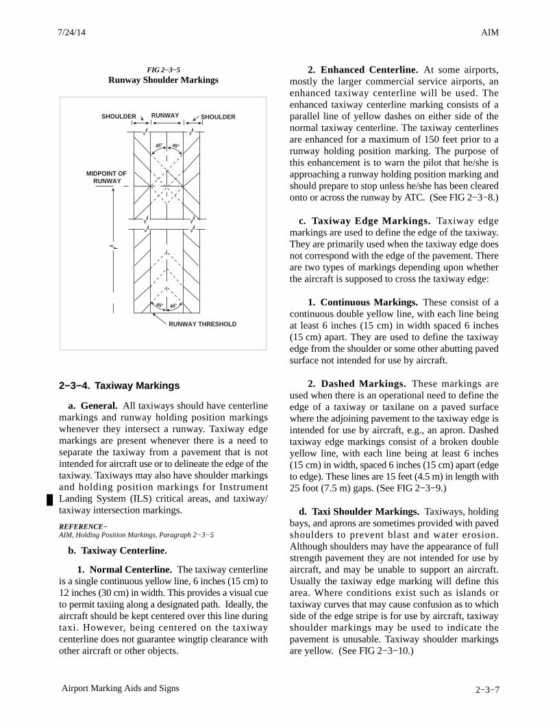
AIM4/3/14
2−3−7Airport Marking Aids and Signs
FIG 2−3−5
Runway Shoulder Markings
RUNWAY THRESHOLD
MIDPOINT OFRUNWAY
SHOULDER SHOULDERRUNWAY
45° 45°
45° 45°
2−3−4. Taxiway Markings
a. General. All taxiways should have centerlinemarkings and runway holding position markingswhenever they intersect a runway. Taxiway edgemarkings are present whenever there is a need toseparate the taxiway from a pavement that is notintended for aircraft use or to delineate the edge of thetaxiway. Taxiways may also have shoulder markingsand holding position markings for InstrumentLanding System (ILS) critical areas, and taxiway/taxiway intersection markings.
REFERENCE−AIM, Holding Position Markings, Paragraph 2−3−5.
b. Taxiway Centerline.
1. Normal Centerline. The taxiway centerlineis a single continuous yellow line, 6 inches (15 cm) to12 inches (30 cm) in width. This provides a visual cueto permit taxiing along a designated path. Ideally, theaircraft should be kept centered over this line duringtaxi. However, being centered on the taxiwaycenterline does not guarantee wingtip clearance withother aircraft or other objects.
2. Enhanced Centerline. At some airports,mostly the larger commercial service airports, anenhanced taxiway centerline will be used. Theenhanced taxiway centerline marking consists of aparallel line of yellow dashes on either side of thenormal taxiway centerline. The taxiway centerlinesare enhanced for a maximum of 150 feet prior to arunway holding position marking. The purpose ofthis enhancement is to warn the pilot that he/she isapproaching a runway holding position marking andshould prepare to stop unless he/she has been clearedonto or across the runway by ATC. (See FIG 2−3−8.)
c. Taxiway Edge Markings. Taxiway edgemarkings are used to define the edge of the taxiway.They are primarily used when the taxiway edge doesnot correspond with the edge of the pavement. Thereare two types of markings depending upon whetherthe aircraft is supposed to cross the taxiway edge:
1. Continuous Markings. These consist of acontinuous double yellow line, with each line beingat least 6 inches (15 cm) in width spaced 6 inches(15 cm) apart. They are used to define the taxiwayedge from the shoulder or some other abutting pavedsurface not intended for use by aircraft.
2. Dashed Markings. These markings areused when there is an operational need to define theedge of a taxiway or taxilane on a paved surfacewhere the adjoining pavement to the taxiway edge isintended for use by aircraft, e.g., an apron. Dashedtaxiway edge markings consist of a broken doubleyellow line, with each line being at least 6 inches(15 cm) in width, spaced 6 inches (15 cm) apart (edgeto edge). These lines are 15 feet (4.5 m) in length with25 foot (7.5 m) gaps. (See FIG 2−3−9.)
d. Taxi Shoulder Markings. Taxiways, holdingbays, and aprons are sometimes provided with pavedshoulders to prevent blast and water erosion.Although shoulders may have the appearance of fullstrength pavement they are not intended for use byaircraft, and may be unable to support an aircraft.Usually the taxiway edge marking will define thisarea. Where conditions exist such as islands ortaxiway curves that may cause confusion as to whichside of the edge stripe is for use by aircraft, taxiwayshoulder markings may be used to indicate thepavement is unusable. Taxiway shoulder markingsare yellow. (See FIG 2−3−10.)
7/24/14 AIM
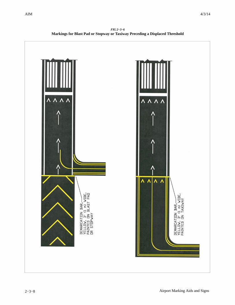
AIM 4/3/14
2−3−8 Airport Marking Aids and Signs
FIG 2−3−6
Markings for Blast Pad or Stopway or Taxiway Preceding a Displaced Threshold
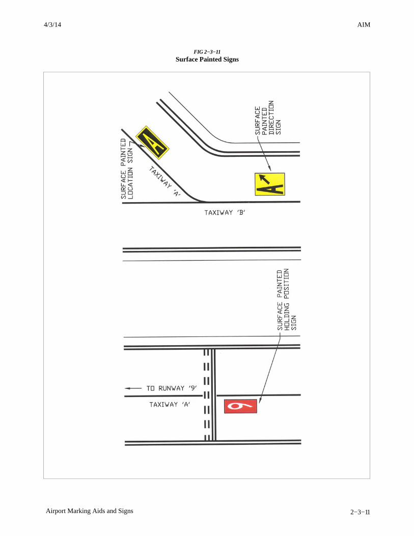
AIM4/3/14
2−3−11Airport Marking Aids and Signs
FIG 2−3−11
Surface Painted Signs
AIM 4/3/14
2−3−12 Airport Marking Aids and Signs
2−3−5. Holding Position Markingsa. Runway Holding Position Markings. For
runways, these markings indicate where an aircraft issupposed to stop when approaching a runway. Theyconsist of four yellow lines, two solid and two dashed,spaced six or twelve inches apart, and extendingacross the width of the taxiway or runway. The solidlines are always on the side where the aircraft is tohold. There are three locations where runway holdingposition markings are encountered.
1. Runway Holding Position Markings onTaxiways. These markings identify the locations ona taxiway where an aircraft is supposed to stop whenit does not have clearance to proceed onto the runway.Generally, runway holding position markings alsoidentify the boundary of the runway safety area foraircraft exiting the runway. The runway holdingposition markings are shown in FIG 2−3−13 andFIG 2−3−16. When instructed by ATC to, “Hold shortof (runway “xx”),” the pilot must stop so that no partof the aircraft extends beyond the runway holdingposition marking. When approaching the runway, apilot should not cross the runway holding positionmarking without ATC clearance at a controlledairport, or without making sure of adequateseparation from other aircraft at uncontrolledairports. An aircraft exiting a runway is not clear ofthe runway until all parts of the aircraft have crossedthe applicable holding position marking.REFERENCE−AIM, Exiting the Runway After Landing,. Paragraph 4−3−20.
2. Runway Holding Position Markings onRunways. These markings are installed on runwaysonly if the runway is normally used by air trafficcontrol for “land, hold short” operations or taxiingoperations and have operational significance only forthose two types of operations. A sign with a whiteinscription on a red background is installed adjacentto these holding position markings. (SeeFIG 2−3−14.) The holding position markings areplaced on runways prior to the intersection withanother runway, or some designated point. Pilotsreceiving instructions “cleared to land, runway “xx””from air traffic control are authorized to use the entirelanding length of the runway and should disregardany holding position markings located on the runway.Pilots receiving and accepting instructions “clearedto land runway “xx,” hold short of runway “yy”” fromair traffic control must either exit runway “xx,” orstop at the holding position prior to runway “yy.”
3. Taxiways Located in Runway Approach
Areas. These markings are used at some airportswhere it is necessary to hold an aircraft on a taxiwaylocated in the approach or departure area of a runwayso that the aircraft does not interfere with theoperations on that runway. This marking is collocatedwith the runway approach area holding position sign.When specifically instructed by ATC “Hold short of(runway xx approach area)” the pilot should stop sono part of the aircraft extends beyond the holdingposition marking. (See subparagraph 2−3−8b2,Runway Approach Area Holding Position Sign, andFIG 2−3−15.)
b. Holding Position Markings for InstrumentLanding System (ILS). Holding position markingsfor ILS critical areas consist of two yellow solid linesspaced two feet apart connected by pairs of solid linesspaced ten feet apart extending across the width of thetaxiway as shown. (See FIG 2−3−16.) A sign with aninscription in white on a red background is installedadjacent to these hold position markings. When theILS critical area is being protected, the pilot shouldstop so no part of the aircraft extends beyond theholding position marking. When approaching theholding position marking, a pilot should not cross themarking without ATC clearance. ILS critical area isnot clear until all parts of the aircraft have crossed theapplicable holding position marking.REFERENCE−AIM, Instrument Landing System (ILS), Paragraph 1−1−9.
c. Holding Position Markings for Taxiway/Taxiway Intersections. Holding position markingsfor taxiway/taxiway intersections consist of a singledashed line extending across the width of the taxiwayas shown. (See FIG 2−3−17.) They are installed ontaxiways where air traffic control normally holdsaircraft short of a taxiway intersection. Wheninstructed by ATC “hold short of (taxiway)” the pilotshould stop so no part of the aircraft extends beyondthe holding position marking. When the marking isnot present the pilot should stop the aircraft at a pointwhich provides adequate clearance from an aircrafton the intersecting taxiway.
d. Surface Painted Holding Position Signs.Surface painted holding position signs have a redbackground with a white inscription and supplementthe signs located at the holding position. This type ofmarking is normally used where the width of theholding position on the taxiway is greater than 200feet(60m). It is located to the left side of the taxiwaycenterline on the holding side and prior to the holdingposition marking. (See FIG 2−3−11.)
3/15/077110.65R CHG 2AIM 7/24/14

AIM4/3/14
4−1−21Services Available to Pilots
f. Everglades Reporting Service.
This service is offered by Miami AutomatedInternational Flight Service Station (MIA AIFSS), inextreme southern Florida. The service is provided toaircraft crossing the Florida Everglades, between LeeCounty (Ft. Myers, FL) VORTAC (RSW) on thenorthwest side, and Dolphin (Miami, FL) VOR(DHP) on the southeast side.
1. The pilot must request the service fromMiami AIFSS.
2. MIA AIFSS frequency information, 122.2,122.3, and 122.65.
3. The pilot must file a VFR flight plan with theremark: ERS.
4. The pilot must maintain 2000 feet of altitude.
5. The pilot must make position reports everyten (10) minutes. SAR begins fifteen (15) minutesafter position report is not made on time.
6. The pilot is expected to land as soon as ispractical, in the event of two−way radio failure, andadvise MIA AIFSS that the service is terminated.
7. The pilot must notify Miami AIFSS when theflight plan is cancelled or the service is suspended.
4−1−22. Airport Reservation Operationsand Special Traffic Management Programs
This section describes procedures for obtainingrequired airport reservations at airports designated bythe FAA and for airports operating under SpecialTraffic Management Programs.
a. Slot Controlled Airports.
1. The FAA may adopt rules to require advanceoperations for unscheduled operations at certainairports. In addition to the information in the rulesadopted by the FAA, a listing of the airports andrelevant information will be maintained on the FAAWeb site listed below.
2. The FAA has established an AirportReservation Office (ARO) to receive and processreservations for unscheduled flights at the slotcontrolled airports. The ARO uses the EnhancedComputer Voice Reservation System (e−CVRS) toallocate reservations. Reservations will be available
beginning 72 hours in advance of the operation at theslot controlled airport. Refer to the Web site ortouch−tone phone interface for the current listing ofslot controlled airports, limitations, and reservationprocedures.
NOTE−The web interface/telephone numbers to obtain areservation for unscheduled operations at a slot controlledairport are:1. http://www.fly.faa.gov/ecvrs.2. Touch−tone: 1−800−875−9694 or 703−707−0568.(e−CVRS interface).3. Trouble number: 540−422−4246.
3. For more detailed information on operationsand reservation procedures at a Slot ControlledAirport, please see Advisory Circular 93−1A,Reservations for Unscheduled Operations at slotcontrolled airports. A copy of the AdvisoryCircular may be obtained via the Internet at:http://www.faa.gov.
b. Special Traffic Management Programs(STMP).
1. Special procedures may be established whena location requires special traffic handling toaccommodate above normal traffic demand (e.g., theIndianapolis 500, Super Bowl) or reduced airportcapacity (e.g., airport runway/taxiway closures forairport construction). The special procedures mayremain in effect until the problem has been resolvedor until local traffic management procedures canhandle the situation and a need for special handling nolonger exists.
2. There will be two methods available forobtaining slot reservations through theATCSCC: the web interface and the touch−toneinterface. If these methods are used, a NOTAM willbe issued relaying the web site address and toll freetelephone number. Be sure to check currentNOTAMs to determine: what airports are includedin the STMP; the dates and times reservations arerequired; the time limits for reservation requests; thepoint of contact for reservations; and any otherinstructions.
c. Users may contact the ARO at 703−904−4452if they have a problem making a reservation or havea question concerning the slot controlled airport/STMP regulations or procedures.
7/24/14 AIM
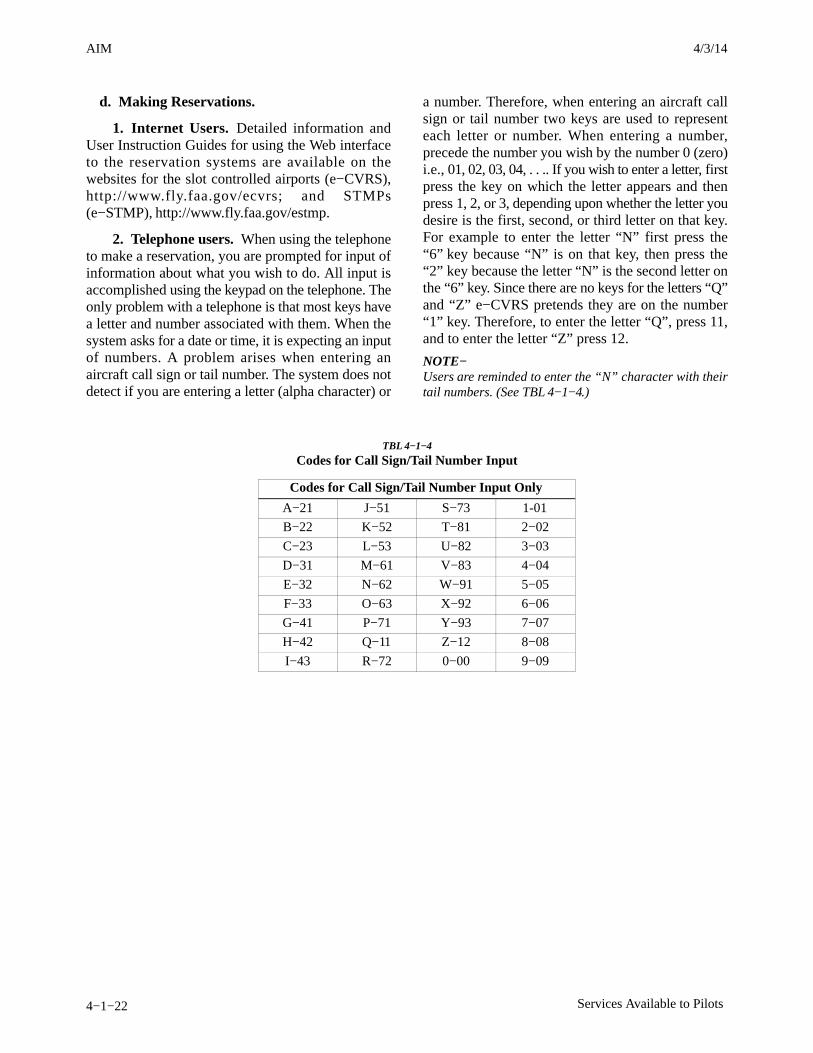
AIM 4/3/14
4−1−22 Services Available to Pilots
d. Making Reservations.
1. Internet Users. Detailed information andUser Instruction Guides for using the Web interfaceto the reservation systems are available on thewebsites for the slot controlled airports (e−CVRS),http://www.fly.faa.gov/ecvrs; and STMPs(e−STMP), http://www.fly.faa.gov/estmp.
2. Telephone users. When using the telephoneto make a reservation, you are prompted for input ofinformation about what you wish to do. All input isaccomplished using the keypad on the telephone. Theonly problem with a telephone is that most keys havea letter and number associated with them. When thesystem asks for a date or time, it is expecting an inputof numbers. A problem arises when entering anaircraft call sign or tail number. The system does notdetect if you are entering a letter (alpha character) or
a number. Therefore, when entering an aircraft callsign or tail number two keys are used to representeach letter or number. When entering a number,precede the number you wish by the number 0 (zero)i.e., 01, 02, 03, 04, . . .. If you wish to enter a letter, firstpress the key on which the letter appears and thenpress 1, 2, or 3, depending upon whether the letter youdesire is the first, second, or third letter on that key.For example to enter the letter “N” first press the“6” key because “N” is on that key, then press the“2” key because the letter “N” is the second letter onthe “6” key. Since there are no keys for the letters “Q”and “Z” e−CVRS pretends they are on the number“1” key. Therefore, to enter the letter “Q”, press 11,and to enter the letter “Z” press 12.
NOTE−Users are reminded to enter the “N” character with theirtail numbers. (See TBL 4−1−4.)
TBL 4−1−4
Codes for Call Sign/Tail Number Input
Codes for Call Sign/Tail Number Input Only
A−21 J−51 S−73 1-01
B−22 K−52 T−81 2−02
C−23 L−53 U−82 3−03
D−31 M−61 V−83 4−04
E−32 N−62 W−91 5−05
F−33 O−63 X−92 6−06
G−41 P−71 Y−93 7−07
H−42 Q−11 Z−12 8−08
I−43 R−72 0−00 9−09

AIM4/3/14
4−3−1Airport Operations
Section 3. Airport Operations
4−3−1. General
Increased traffic congestion, aircraft in climb anddescent attitudes, and pilot preoccupation withcockpit duties are some factors that increase thehazardous accident potential near the airport. Thesituation is further compounded when the weather ismarginal, that is, just meeting VFR requirements.Pilots must be particularly alert when operating in thevicinity of an airport. This section defines some rules,practices, and procedures that pilots should befamiliar with and adhere to for safe airport operations.
4−3−2. Airports with an Operating ControlTower
a. When operating at an airport where trafficcontrol is being exercised by a control tower, pilotsare required to maintain two−way radio contact withthe tower while operating within the Class B, Class C,and Class D surface area unless the tower authorizesotherwise. Initial callup should be made about15 miles from the airport. Unless there is a goodreason to leave the tower frequency before exiting theClass B, Class C, and Class D surface areas, it is agood operating practice to remain on the towerfrequency for the purpose of receiving trafficinformation. In the interest of reducing towerfrequency congestion, pilots are reminded that it isnot necessary to request permission to leave the towerfrequency once outside of Class B, Class C, andClass D surface areas. Not all airports with anoperating control tower will have Class D airspace.These airports do not have weather reporting whichis a requirement for surface based controlledairspace, previously known as a control zone. Thecontrolled airspace over these airports will normallybegin at 700 feet or 1,200 feet above ground level andcan be determined from the visual aeronauticalcharts. Pilots are expected to use good operatingpractices and communicate with the control tower asdescribed in this section.
b. When necessary, the tower controller will issueclearances or other information for aircraft togenerally follow the desired flight path (trafficpatterns) when flying in Class B, Class C, and Class Dsurface areas and the proper taxi routes whenoperating on the ground. If not otherwise authorized
or directed by the tower, pilots of fixed−wing aircraftapproaching to land must circle the airport to the left.Pilots approaching to land in a helicopter must avoidthe flow of fixed−wing traffic. However, in allinstances, an appropriate clearance must be receivedfrom the tower before landing.
FIG 4−3−1
Components of a Traffic Pattern
NOTE−This diagram is intended only to illustrate terminologyused in identifying various components of a traffic pattern.It should not be used as a reference or guide on how to entera traffic pattern.
c. The following terminology for the variouscomponents of a traffic pattern has been adopted asstandard for use by control towers and pilots (SeeFIG 4−3−1):
1. Upwind leg. A flight path parallel to thelanding runway in the direction of landing.
2. Crosswind leg. A flight path at right anglesto the landing runway off its takeoff end.
3. Downwind leg. A flight path parallel to thelanding runway in the opposite direction of landing.
4. Base leg. A flight path at right angles to thelanding runway off its approach end and extendingfrom the downwind leg to the intersection of theextended runway centerline.
5. Final approach. A flight path in thedirection of landing along the extended runwaycenterline from the base leg to the runway.
6. Departure leg. The flight path which beginsafter takeoff and continues straight ahead along theextended runway centerline. The departure climbcontinues until reaching a point at least 1/2 mile
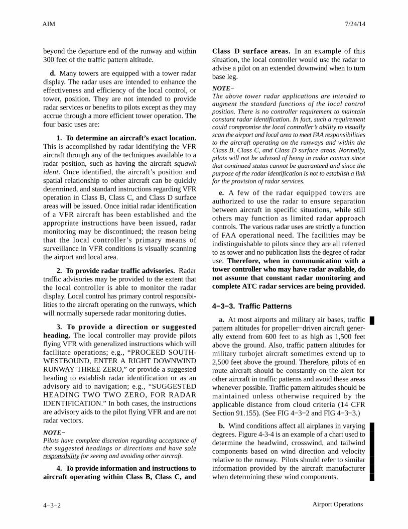
AIM 4/3/14
4−3−2 Airport Operations
beyond the departure end of the runway and within300 feet of the traffic pattern altitude.
d. Many towers are equipped with a tower radardisplay. The radar uses are intended to enhance theeffectiveness and efficiency of the local control, ortower, position. They are not intended to provideradar services or benefits to pilots except as they mayaccrue through a more efficient tower operation. Thefour basic uses are:
1. To determine an aircraft’s exact location.This is accomplished by radar identifying the VFRaircraft through any of the techniques available to aradar position, such as having the aircraft squawkident. Once identified, the aircraft’s position andspatial relationship to other aircraft can be quicklydetermined, and standard instructions regarding VFRoperation in Class B, Class C, and Class D surfaceareas will be issued. Once initial radar identificationof a VFR aircraft has been established and theappropriate instructions have been issued, radarmonitoring may be discontinued; the reason beingthat the local controller’s primary means ofsurveillance in VFR conditions is visually scanningthe airport and local area.
2. To provide radar traffic advisories. Radartraffic advisories may be provided to the extent thatthe local controller is able to monitor the radardisplay. Local control has primary control responsibi-lities to the aircraft operating on the runways, whichwill normally supersede radar monitoring duties.
3. To provide a direction or suggestedheading. The local controller may provide pilotsflying VFR with generalized instructions which willfacilitate operations; e.g., “PROCEED SOUTH-WESTBOUND, ENTER A RIGHT DOWNWINDRUNWAY THREE ZERO,” or provide a suggestedheading to establish radar identification or as anadvisory aid to navigation; e.g., “SUGGESTEDHEADING TWO TWO ZERO, FOR RADARIDENTIFICATION.” In both cases, the instructionsare advisory aids to the pilot flying VFR and are notradar vectors.
NOTE−Pilots have complete discretion regarding acceptance ofthe suggested headings or directions and have soleresponsibility for seeing and avoiding other aircraft.
4. To provide information and instructions toaircraft operating within Class B, Class C, and
Class D surface areas. In an example of thissituation, the local controller would use the radar toadvise a pilot on an extended downwind when to turnbase leg.
NOTE−The above tower radar applications are intended toaugment the standard functions of the local controlposition. There is no controller requirement to maintainconstant radar identification. In fact, such a requirementcould compromise the local controller’s ability to visuallyscan the airport and local area to meet FAA responsibilitiesto the aircraft operating on the runways and within theClass B, Class C, and Class D surface areas. Normally,pilots will not be advised of being in radar contact sincethat continued status cannot be guaranteed and since thepurpose of the radar identification is not to establish a linkfor the provision of radar services.
e. A few of the radar equipped towers areauthorized to use the radar to ensure separationbetween aircraft in specific situations, while stillothers may function as limited radar approachcontrols. The various radar uses are strictly a functionof FAA operational need. The facilities may beindistinguishable to pilots since they are all referredto as tower and no publication lists the degree of radaruse. Therefore, when in communication with atower controller who may have radar available, donot assume that constant radar monitoring andcomplete ATC radar services are being provided.
4−3−3. Traffic Patterns
a. At most airports and military air bases, trafficpattern altitudes for propeller−driven aircraft gener-ally extend from 600 feet to as high as 1,500 feetabove the ground. Also, traffic pattern altitudes formilitary turbojet aircraft sometimes extend up to2,500 feet above the ground. Therefore, pilots of enroute aircraft should be constantly on the alert forother aircraft in traffic patterns and avoid these areaswhenever possible. Traffic pattern altitudes should bemaintained unless otherwise required by theapplicable distance from cloud criteria (14 CFRSection 91.155). (See FIG 4−3−2 and FIG 4−3−3.)
b. Wind conditions affect all airplanes in varyingdegrees. Figure 4-3-4 is an example of a chart used todetermine the headwind, crosswind, and tailwindcomponents based on wind direction and velocityrelative to the runway. Pilots should refer to similarinformation provided by the aircraft manufacturerwhen determining these wind components.
3/15/077110.65R CHG 2AIM 7/24/14

AIM4/3/14
4−3−3Airport Operations
FIG 4−3−2
Traffic Pattern OperationsSingle Runway
EXAMPLE−Key to traffic pattern operations
1. Enter pattern in level flight, abeam the midpoint of therunway, at pattern altitude. (1,000’ AGL is recommendedpattern altitude unless established otherwise. . .)
2. Maintain pattern altitude until abeam approach end ofthe landing runway on downwind leg.
3. Complete turn to final at least 1/4 mile from the runway.
4. Continue straight ahead until beyond departure end ofrunway.
5. If remaining in the traffic pattern, commence turn tocrosswind leg beyond the departure end of the runwaywithin 300 feet of pattern altitude.
6. If departing the traffic pattern, continue straight out, orexit with a 45 degree turn (to the left when in a left−handtraffic pattern; to the right when in a right−hand trafficpattern) beyond the departure end of the runway, afterreaching pattern altitude.
7/24/14 AIM
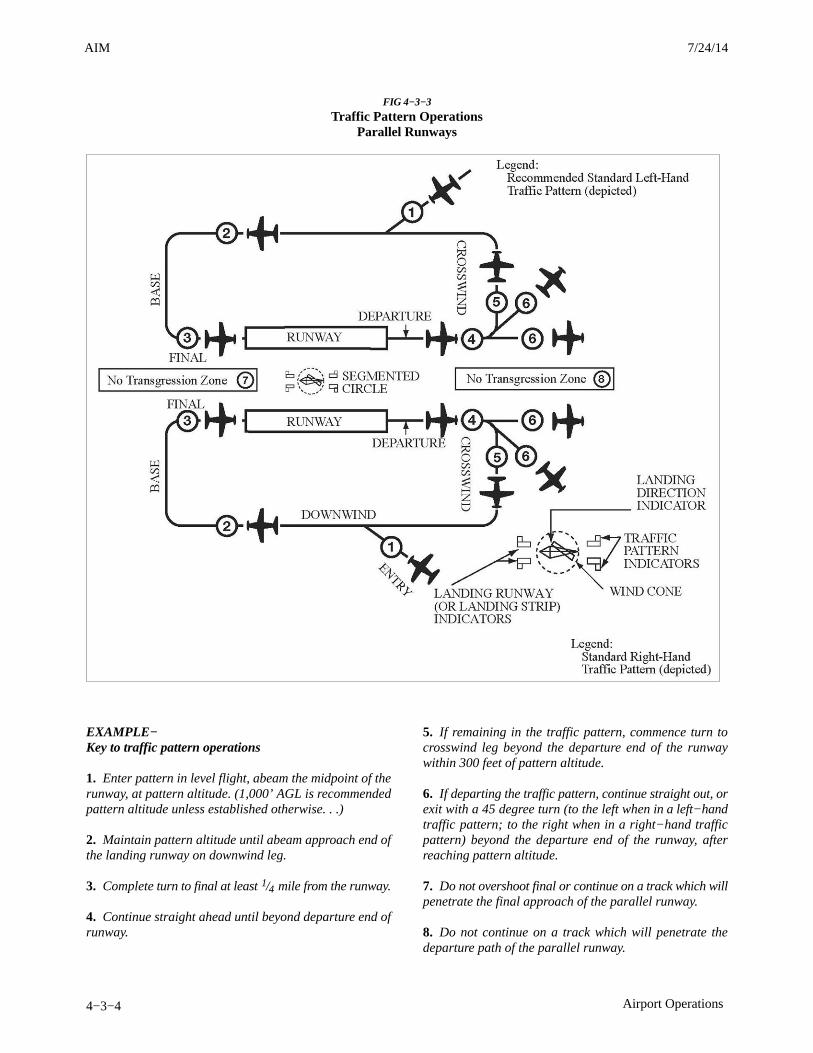
AIM 4/3/14
4−3−4 Airport Operations
FIG 4−3−3
Traffic Pattern OperationsParallel Runways
EXAMPLE−Key to traffic pattern operations
1. Enter pattern in level flight, abeam the midpoint of therunway, at pattern altitude. (1,000’ AGL is recommendedpattern altitude unless established otherwise. . .)
2. Maintain pattern altitude until abeam approach end ofthe landing runway on downwind leg.
3. Complete turn to final at least 1/4 mile from the runway.
4. Continue straight ahead until beyond departure end ofrunway.
5. If remaining in the traffic pattern, commence turn tocrosswind leg beyond the departure end of the runwaywithin 300 feet of pattern altitude.
6. If departing the traffic pattern, continue straight out, orexit with a 45 degree turn (to the left when in a left−handtraffic pattern; to the right when in a right−hand trafficpattern) beyond the departure end of the runway, afterreaching pattern altitude.
7. Do not overshoot final or continue on a track which willpenetrate the final approach of the parallel runway.
8. Do not continue on a track which will penetrate thedeparture path of the parallel runway.
3/15/077110.65R CHG 2AIM 7/24/14
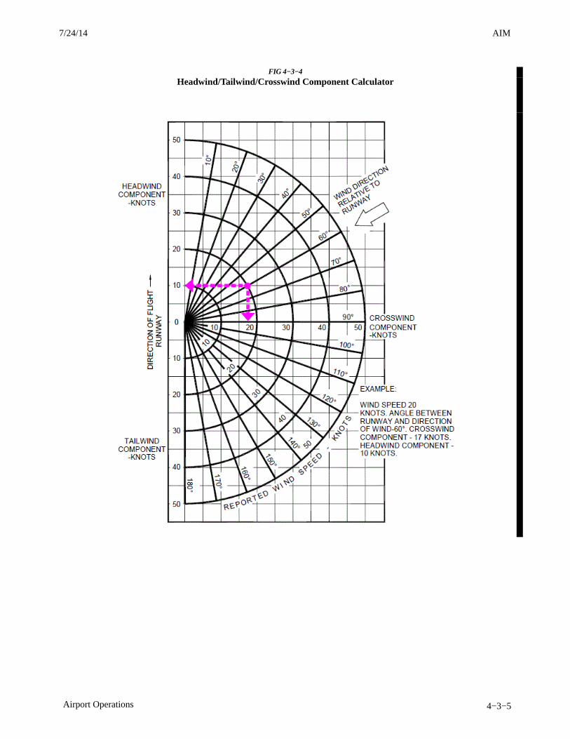
AIM4/3/14
4−3−5Airport Operations
FIG 4−3−4
Headwind/Tailwind/Crosswind Component Calculator
7/24/14 AIM
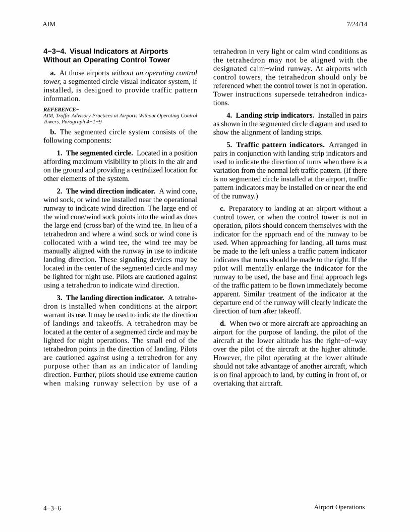
AIM 4/3/14
4−3−6 Airport Operations
4−3−4. Visual Indicators at AirportsWithout an Operating Control Tower
a. At those airports without an operating controltower, a segmented circle visual indicator system, ifinstalled, is designed to provide traffic patterninformation.
REFERENCE−AIM, Traffic Advisory Practices at Airports Without Operating ControlTowers, Paragraph 4−1−9.
b. The segmented circle system consists of thefollowing components:
1. The segmented circle. Located in a positionaffording maximum visibility to pilots in the air andon the ground and providing a centralized location forother elements of the system.
2. The wind direction indicator. A wind cone,wind sock, or wind tee installed near the operationalrunway to indicate wind direction. The large end ofthe wind cone/wind sock points into the wind as doesthe large end (cross bar) of the wind tee. In lieu of atetrahedron and where a wind sock or wind cone iscollocated with a wind tee, the wind tee may bemanually aligned with the runway in use to indicatelanding direction. These signaling devices may belocated in the center of the segmented circle and maybe lighted for night use. Pilots are cautioned againstusing a tetrahedron to indicate wind direction.
3. The landing direction indicator. A tetrahe-dron is installed when conditions at the airportwarrant its use. It may be used to indicate the directionof landings and takeoffs. A tetrahedron may belocated at the center of a segmented circle and may belighted for night operations. The small end of thetetrahedron points in the direction of landing. Pilotsare cautioned against using a tetrahedron for anypurpose other than as an indicator of landingdirection. Further, pilots should use extreme cautionwhen making runway selection by use of a
tetrahedron in very light or calm wind conditions asthe tetrahedron may not be aligned with thedesignated calm−wind runway. At airports withcontrol towers, the tetrahedron should only bereferenced when the control tower is not in operation.Tower instructions supersede tetrahedron indica-tions.
4. Landing strip indicators. Installed in pairsas shown in the segmented circle diagram and used toshow the alignment of landing strips.
5. Traffic pattern indicators. Arranged inpairs in conjunction with landing strip indicators andused to indicate the direction of turns when there is avariation from the normal left traffic pattern. (If thereis no segmented circle installed at the airport, trafficpattern indicators may be installed on or near the endof the runway.)
c. Preparatory to landing at an airport without acontrol tower, or when the control tower is not inoperation, pilots should concern themselves with theindicator for the approach end of the runway to beused. When approaching for landing, all turns mustbe made to the left unless a traffic pattern indicatorindicates that turns should be made to the right. If thepilot will mentally enlarge the indicator for therunway to be used, the base and final approach legsof the traffic pattern to be flown immediately becomeapparent. Similar treatment of the indicator at thedeparture end of the runway will clearly indicate thedirection of turn after takeoff.
d. When two or more aircraft are approaching anairport for the purpose of landing, the pilot of theaircraft at the lower altitude has the right−of−wayover the pilot of the aircraft at the higher altitude.However, the pilot operating at the lower altitudeshould not take advantage of another aircraft, whichis on final approach to land, by cutting in front of, orovertaking that aircraft.
3/15/077110.65R CHG 2AIM 7/24/14
AIM4/3/14
4−3−7Airport Operations
4−3−5. Unexpected Maneuvers in theAirport Traffic Pattern
There have been several incidents in the vicinity ofcontrolled airports that were caused primarily byaircraft executing unexpected maneuvers. ATCservice is based upon observed or known traffic andairport conditions. Controllers establish the sequenceof arriving and departing aircraft by requiring them toadjust flight as necessary to achieve proper spacing.These adjustments can only be based on observedtraffic, accurate pilot reports, and anticipated aircraftmaneuvers. Pilots are expected to cooperate so as topreclude disrupting traffic flows or creatingconflicting patterns. The pilot−in−command of anaircraft is directly responsible for and is the finalauthority as to the operation of the aircraft. Onoccasion it may be necessary for pilots to maneuvertheir aircraft to maintain spacing with the traffic theyhave been sequenced to follow. The controller cananticipate minor maneuvering such as shallow “S”turns. The controller cannot, however, anticipate amajor maneuver such as a 360 degree turn. If a pilotmakes a 360 degree turn after obtaining a landingsequence, the result is usually a gap in the landinginterval and, more importantly, it causes a chainreaction which may result in a conflict with followingtraffic and an interruption of the sequence establishedby the tower or approach controller. Should a pilotdecide to make maneuvering turns to maintainspacing behind a preceding aircraft, the pilot shouldalways advise the controller if at all possible. Exceptwhen requested by the controller or in emergencysituations, a 360 degree turn should never be executedin the traffic pattern or when receiving radar servicewithout first advising the controller.
4−3−6. Use of Runways/Declared Distances
a. Runways are identified by numbers whichindicate the nearest 10−degree increment of theazimuth of the runway centerline. For example,where the magnetic azimuth is 183 degrees, therunway designation would be 18; for a magneticazimuth of 87 degrees, the runway designation wouldbe 9. For a magnetic azimuth ending in the number 5,such as 185, the runway designation could be either18 or 19. Wind direction issued by the tower is alsomagnetic and wind velocity is in knots.
b. Airport proprietors are responsible for takingthe lead in local aviation noise control. Accordingly,
they may propose specific noise abatement plans tothe FAA. If approved, these plans are applied in theform of Formal or Informal Runway Use Programsfor noise abatement purposes.REFERENCE−Pilot/Controller Glossary Term− “Runway Use Program”
1. At airports where no runway use program isestablished, ATC clearances may specify:
(a) The runway most nearly aligned with thewind when it is 5 knots or more;
(b) The “calm wind” runway when wind isless than 5 knots; or
(c) Another runway if operationally advanta-geous.
NOTE−It is not necessary for a controller to specifically inquire ifthe pilot will use a specific runway or to offer a choice ofrunways. If a pilot prefers to use a different runway fromthat specified, or the one most nearly aligned with the wind,the pilot is expected to inform ATC accordingly.
2. At airports where a runway use program isestablished, ATC will assign runways deemed to havethe least noise impact. If in the interest of safety arunway different from that specified is preferred, thepilot is expected to advise ATC accordingly. ATC willhonor such requests and advise pilots when therequested runway is noise sensitive. When use of arunway other than the one assigned is requested, pilotcooperation is encouraged to preclude disruption oftraffic flows or the creation of conflicting patterns.
c. Declared Distances.
1. Declared distances for a runway representthe maximum distances available and suitable formeeting takeoff and landing distance performancerequirements. These distances are determined inaccordance with FAA runway design standards byadding to the physical length of paved runway anyclearway or stopway and subtracting from that sumany lengths necessary to obtain the standard runwaysafety areas, runway object free areas, or runwayprotection zones. As a result of these additions andsubtractions, the declared distances for a runway maybe more or less than the physical length of the runwayas depicted on aeronautical charts and relatedpublications, or available in electronic navigationdatabases provided by either the U.S. Government orcommercial companies.
2. All 14 CFR Part 139 airports report declareddistances for each runway. Other airports may also
7/24/14 AIM
AIM 4/3/14
4−3−8 Airport Operations
report declared distances for a runway if necessaryto meet runway design standards or to indicate thepresence of a clearway or stopway. Where reported,declared distances for each runway end arepublished in the Airport/Facility Directory (A/FD).For runways without published declared distances,the declared distances may be assumed to be equal tothe physical length of the runway unless there is adisplaced landing threshold, in which case theLanding Distance Available (LDA) is shortened bythe amount of the threshold displacement.
NOTE−A symbol is shown on U.S. Government charts toindicate that runway declared distance information isavailable (See appropriate A/FD, Alaska, or PacificSupplement).
(a) The FAA uses the following definitionsfor runway declared distances (See FIG 4−3−5):
REFERENCE−Pilot/Controller Glossary Terms: “Accelerate−Stop DistanceAvailable,” “Landing Distance Available,” “Takeoff DistanceAvailable,” “Takeoff Run Available,” ” Stopway,” and “Clearway.”
(1) Takeoff Run Available (TORA) – Therunway length declared available and suitable forthe ground run of an airplane taking off.
The TORA is typically the physical length of therunway, but it may be shorter than the runway lengthif necessary to satisfy runway design standards. Forexample, the TORA may be shorter than the runwaylength if a portion of the runway must be used tosatisfy runway protection zone requirements.
(2) Takeoff Distance Available (TODA) –The takeoff run available plus the length of anyremaining runway or clearway beyond the far end ofthe takeoff run available.
The TODA is the distance declared available forsatisfying takeoff distance requirements for airplaneswhere the certification and operating rules andavailable performance data allow for the considera-tion of a clearway in takeoff performancecomputations.
NOTE−The length of any available clearway will be included in theTODA published in the A/FD’s entry for that runway end.
(3) Accelerate−Stop Distance Available(ASDA) – The runway plus stopway length declaredavailable and suitable for the acceleration anddeceleration of an airplane aborting a takeoff.
The ASDA may be longer than the physical length ofthe runway when a stopway has been designatedavailable by the airport operator, or it may be shorterthan the physical length of the runway if necessary touse a portion of the runway to satisfy runway designstandards; for example, where the airport operatoruses a portion of the runway to achieve the runwaysafety area requirement. ASDA is the distance usedto satisfy the airplane accelerate−stop distanceperformance requirements where the certificationand operating rules require accelerate−stop distancecomputations.
NOTE−The length of any available stopway will be included in theASDA published in the A/FD’s entry for that runway end.
(4) Landing Distance Available (LDA) −The runway length declared available and suitablefor a landing airplane.
The LDA may be less than the physical length of therunway or the length of the runway remaining beyonda displaced threshold if necessary to satisfy runwaydesign standards;for example, where the airportoperator uses a portion of the runway to achieve therunway safety area requirement.
Although some runway elements (such as stopwaylength and clearway length) may be availableinformation, pilots must use the declared distancesdetermined by the airport operator and not attempt toindependently calculate declared distances byadding those elements to the reported physicallength of the runway.
(b) The airplane operating rules and/or theairplane operating limitations establish minimumdistance requirements for takeoff and landing andare based on performance data supplied in theAirplane Flight Manual or Pilot’s OperatingHandbook. The minimum distances required fortakeoff and landing obtained either in planningprior to takeoff or in performance assessmentsconducted at the time of landing must fall within theapplicable declared distances before the pilot canaccept that runway for takeoff or landing.
(c) Runway design standards may imposerestrictions on the amount of runway available foruse in takeoff and landing that are not apparentfrom the reported physical length of the runway orfrom runway markings and lighting. The runwayelements of Runway Safety Area (RSA), RunwayObject Free Area (ROFA), and Runway Protection
3/15/077110.65R CHG 2AIM 7/24/14

AIM4/3/14
4−3−9Airport Operations
Zone (RPZ) may reduce a runway’s declareddistances to less than the physical length of therunway at geographically constrained airports (SeeFIG 4−3−6). When considering the amount ofrunway available for use in takeoff or landingperformance calculations, the declared distancespublished for a runway must always be used in lieuof the runway’s physical length.REFERENCE−AC 150/5300−13, Airport Design.
(d) While some runway elements associatedwith declared distances may be identifiable throughrunway markings or lighting (for example, adisplaced threshold or a stopway), the individualdeclared distance limits are not marked or otherwiseidentified on the runway. An aircraft is notprohibited from operating beyond a declareddistance limit during the takeoff, landing, or taxioperation provided the runway surface is appropri-ately marked as usable runway (See FIG 4−3−6). Thefollowing examples clarify the intent of thisparagraph.
REFERENCE−AIM, Runway Markings, Paragraph 2−3−3.AC 150/5340−1, Standards for Airport Markings.
EXAMPLE−1. The declared LDA for runway 9 must be used whenshowing compliance with the landing distance require-ments of the applicable airplane operating rules and/orairplane operating limitations or when making a beforelanding performance assessment. The LDA is less than thephysical runway length, not only because of the displacedthreshold, but also because of the subtractions necessaryto meet the RSA beyond the far end of the runway. However,during the actual landing operation, it is permissible forthe airplane to roll beyond the unmarked end of the LDA.
2. The declared ASDA for runway 9 must be used whenshowing compliance with the accelerate−stop distancerequirements of the applicable airplane operating rulesand/or airplane operating limitations. The ASDA is lessthan the physical length of the runway due to subtractionsnecessary to achieve the full RSA requirement. However, inthe event of an aborted takeoff, it is permissible for theairplane to roll beyond the unmarked end of the ASDA asit is brought to a full−stop on the remaining usable runway.
7/24/14 AIM

AIM 4/3/14
4−3−10 Airport Operations
FIG 4−3−5
Declared Distances with Full−Standard Runway Safety Areas, Runway Object Free Areas, and RunwayProtection Zones
3/15/077110.65R CHG 2AIM 7/24/14

AIM4/3/14
4−3−11Airport Operations
FIG 4−3−6
Effects of a Geographical Constraint on a Runway’s Declared Distances
NOTE−A runway’s RSA begins a set distance prior to the threshold and will extend a set distance beyond the end of the runwaydepending on the runway’s design criteria. If these required lengths cannot be achieved, the ASDA and/or LDA will bereduced as necessary to obtain the required lengths to the extent practicable.
7/24/14 AIM
AIM 4/3/14
4−3−12 Airport Operations
4−3−7. Low Level Wind Shear/MicroburstDetection Systems
Low Level Wind Shear Alert System (LLWAS),Terminal Doppler Weather Radar (TDWR), WeatherSystem Processor (WSP), and Integrated TerminalWeather System (ITWS) display information onhazardous wind shear and microburst activity in thevicinity of an airport to air traffic controllers whorelay this information to pilots.
a. LLWAS provides wind shear alert and gust frontinformation but does not provide microburst alerts.The LLWAS is designed to detect low level windshear conditions around the periphery of an airport. Itdoes not detect wind shear beyond that limitation.Controllers will provide this information to pilots bygiving the pilot the airport wind followed by theboundary wind.
EXAMPLE−Wind shear alert, airport wind 230 at 8, south boundarywind 170 at 20.
b. LLWAS “network expansion,” (LLWAS NE)and LLWAS Relocation/Sustainment (LLWAS−RS)are systems integrated with TDWR. These systemsprovide the capability of detecting microburst alertsand wind shear alerts. Controllers will issue theappropriate wind shear alerts or microburst alerts. Insome of these systems controllers also have the abilityto issue wind information oriented to the threshold ordeparture end of the runway.
EXAMPLE−Runway 17 arrival microburst alert, 40 knot loss 3 milefinal.
REFERENCE−AIM, Microbursts, Paragraph 7−1−26.
c. More advanced systems are in the field or beingdeveloped such as ITWS. ITWS provides alerts formicrobursts, wind shear, and significant thunder-storm activity. ITWS displays wind informationoriented to the threshold or departure end of therunway.
d. The WSP provides weather processor enhance-ments to selected Airport Surveillance Radar(ASR)−9 facilities. The WSP provides Air Trafficwith detection and alerting of hazardous weather suchas wind shear, microbursts, and significant thunder-storm activity. The WSP displays terminal area6 level weather, storm cell locations and movement,as well as the location and predicted future position
and intensity of wind shifts that may affect airportoperations. Controllers will receive and issue alertsbased on Areas Noted for Attention (ARENA). AnARENA extends on the runway center line from a3 mile final to the runway to a 2 mile departure.
e. An airport equipped with the LLWAS, ITWS, orWSP is so indicated in the Airport/Facility Directoryunder Weather Data Sources for that particularairport.
4−3−8. Braking Action Reports andAdvisories
a. When available, ATC furnishes pilots thequality of braking action received from pilots orairport management. The quality of braking action isdescribed by the terms “good,” “fair,” “poor,” and“nil,” or a combination of these terms. When pilotsreport the quality of braking action by using the termsnoted above, they should use descriptive terms thatare easily understood, such as, “braking action poorthe first/last half of the runway,” together with theparticular type of aircraft.
b. For NOTAM purposes, braking action reportsare classified according to the most critical term(“fair,” “poor,” or “nil”) used and issued as aNOTAM(D).
c. When tower controllers have received runwaybraking action reports which include the terms pooror nil, or whenever weather conditions are conduciveto deteriorating or rapidly changing runway brakingconditions, the tower will include on the ATISbroadcast the statement, “BRAKING ACTIONADVISORIES ARE IN EFFECT.”
d. During the time that braking action advisoriesare in effect, ATC will issue the latest braking actionreport for the runway in use to each arriving anddeparting aircraft. Pilots should be prepared fordeteriorating braking conditions and should requestcurrent runway condition information if notvolunteered by controllers. Pilots should also beprepared to provide a descriptive runway conditionreport to controllers after landing.
4−3−9. Runway Friction Reports andAdvisories
a. Friction is defined as the ratio of the tangentialforce needed to maintain uniform relative motionbetween two contacting surfaces (aircraft tires to the
3/15/077110.65R CHG 2AIM 7/24/14
AIM4/3/14
4−3−13Airport Operations
pavement surface) to the perpendicular force holdingthem in contact (distributed aircraft weight to theaircraft tire area). Simply stated, friction quantifiesslipperiness of pavement surfaces.
b. The greek letter MU (pronounced “myew”), isused to designate a friction value representingrunway surface conditions.
c. MU (friction) values range from 0 to 100 wherezero is the lowest friction value and 100 is themaximum friction value obtainable. For frozencontaminants on runway surfaces, a MU value of40 or less is the level when the aircraft brakingperformance starts to deteriorate and directionalcontrol begins to be less responsive. The lower theMU value, the less effective braking performancebecomes and the more difficult directional controlbecomes.
d. At airports with friction measuring devices,airport management should conduct friction mea-surements on runways covered with compacted snowand/or ice.
1. Numerical readings may be obtained by usingany FAA approved friction measuring device. Asthese devices do not provide equal numericalreadings on contaminated surfaces, it is necessary todesignate the type of friction measuring device used.
2. When the MU value for any one−third zone ofan active runway is 40 or less, a report should be givento ATC by airport management for dissemination topilots. The report will identify the runway, the time ofmeasurement, the type of friction measuring deviceused, MU values for each zone, and the contaminantconditions, e.g., wet snow, dry snow, slush, deicingchemicals, etc. Measurements for each one−thirdzone will be given in the direction of takeoff andlanding on the runway. A report should also be givenwhen MU values rise above 40 in all zones of arunway previously reporting a MU below 40.
3. Airport management should initiate aNOTAM(D) when the friction measuring device isout of service.
e. When MU reports are provided by airportmanagement, the ATC facility providing approachcontrol or local airport advisory will provide thereport to any pilot upon request.
f. Pilots should use MU information with otherknowledge including aircraft performance character-
istics, type, and weight, previous experience, windconditions, and aircraft tire type (i.e., bias ply vs.radial constructed) to determine runway suitability.
g. No correlation has been established betweenMU values and the descriptive terms “good,” “fair,”“poor,” and “nil” used in braking action reports.
4−3−10. Intersection Takeoffs
a. In order to enhance airport capacities, reducetaxiing distances, minimize departure delays, andprovide for more efficient movement of air traffic,controllers may initiate intersection takeoffs as wellas approve them when the pilot requests. If for ANYreason a pilot prefers to use a different intersection orthe full length of the runway or desires to obtain thedistance between the intersection and the runway end,THE PILOT IS EXPECTED TO INFORM ATCACCORDINGLY.
b. Pilots are expected to assess the suitability of anintersection for use at takeoff during their preflightplanning. They must consider the resultant lengthreduction to the published runway length and to thepublished declared distances from the intersectionintended to be used for takeoff. The minimum runwayrequired for takeoff must fall within the reducedrunway length and the reduced declared distancesbefore the intersection can be accepted for takeoff.REFERENCE−AIM, Use of Runways/Declared Distances, Paragraph 4−3−6.
c. Controllers will issue the measured distancefrom the intersection to the runway end rounded“down” to the nearest 50 feet to any pilot whorequests and to all military aircraft, unless use of theintersection is covered in appropriate directives.Controllers, however, will not be able to inform pilotsof the distance from the intersection to the end of anyof the published declared distances.REFERENCE−FAAO JO 7110.65, Ground Traffic Movement, Paragraph 3−7−1.
d. An aircraft is expected to taxi to (but not onto)the end of the assigned runway unless prior approvalfor an intersection departure is received from groundcontrol.
e. Pilots should state their position on the airportwhen calling the tower for takeoff from a runwayintersection.EXAMPLE−Cleveland Tower, Apache Three Seven Two Two Papa, atthe intersection of taxiway Oscar and runway two threeright, ready for departure.
7/24/14 AIM
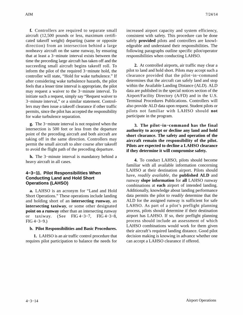
AIM 4/3/14
4−3−14 Airport Operations
f. Controllers are required to separate smallaircraft (12,500 pounds or less, maximum certifi-cated takeoff weight) departing (same or oppositedirection) from an intersection behind a largenonheavy aircraft on the same runway, by ensuringthat at least a 3−minute interval exists between thetime the preceding large aircraft has taken off and thesucceeding small aircraft begins takeoff roll. Toinform the pilot of the required 3−minute hold, thecontroller will state, “Hold for wake turbulence.” Ifafter considering wake turbulence hazards, the pilotfeels that a lesser time interval is appropriate, the pilotmay request a waiver to the 3−minute interval. Toinitiate such a request, simply say “Request waiver to3−minute interval,” or a similar statement. Control-lers may then issue a takeoff clearance if other trafficpermits, since the pilot has accepted the responsibilityfor wake turbulence separation.
g. The 3−minute interval is not required when theintersection is 500 feet or less from the departurepoint of the preceding aircraft and both aircraft aretaking off in the same direction. Controllers maypermit the small aircraft to alter course after takeoffto avoid the flight path of the preceding departure.
h. The 3−minute interval is mandatory behind aheavy aircraft in all cases.
4−3−11. Pilot Responsibilities WhenConducting Land and Hold ShortOperations (LAHSO)
a. LAHSO is an acronym for “Land and HoldShort Operations.” These operations include landingand holding short of an intersecting runway, anintersecting taxiway, or some other designatedpoint on a runway other than an intersecting runwayor taxiway. (See FIG 4−3−7, FIG 4−3−8,FIG 4−3−9.)
b. Pilot Responsibilities and Basic Procedures.
1. LAHSO is an air traffic control procedure thatrequires pilot participation to balance the needs for
increased airport capacity and system efficiency,consistent with safety. This procedure can be donesafely provided pilots and controllers are knowl-edgeable and understand their responsibilities. Thefollowing paragraphs outline specific pilot/operatorresponsibilities when conducting LAHSO.
2. At controlled airports, air traffic may clear apilot to land and hold short. Pilots may accept such aclearance provided that the pilot−in−commanddetermines that the aircraft can safely land and stopwithin the Available Landing Distance (ALD). ALDdata are published in the special notices section of theAirport/Facility Directory (A/FD) and in the U.S.Terminal Procedures Publications. Controllers willalso provide ALD data upon request. Student pilots orpilots not familiar with LAHSO should notparticipate in the program.
3. The pilot−in−command has the finalauthority to accept or decline any land and holdshort clearance. The safety and operation of theaircraft remain the responsibility of the pilot.Pilots are expected to decline a LAHSO clearanceif they determine it will compromise safety.
4. To conduct LAHSO, pilots should becomefamiliar with all available information concerningLAHSO at their destination airport. Pilots shouldhave, readily available, the published ALD andrunway slope information for all LAHSO runwaycombinations at each airport of intended landing.Additionally, knowledge about landing performancedata permits the pilot to readily determine that theALD for the assigned runway is sufficient for safeLAHSO. As part of a pilot’s preflight planningprocess, pilots should determine if their destinationairport has LAHSO. If so, their preflight planningprocess should include an assessment of whichLAHSO combinations would work for them giventheir aircraft’s required landing distance. Good pilotdecision making is knowing in advance whether onecan accept a LAHSO clearance if offered.
3/15/077110.65R CHG 2AIM 7/24/14
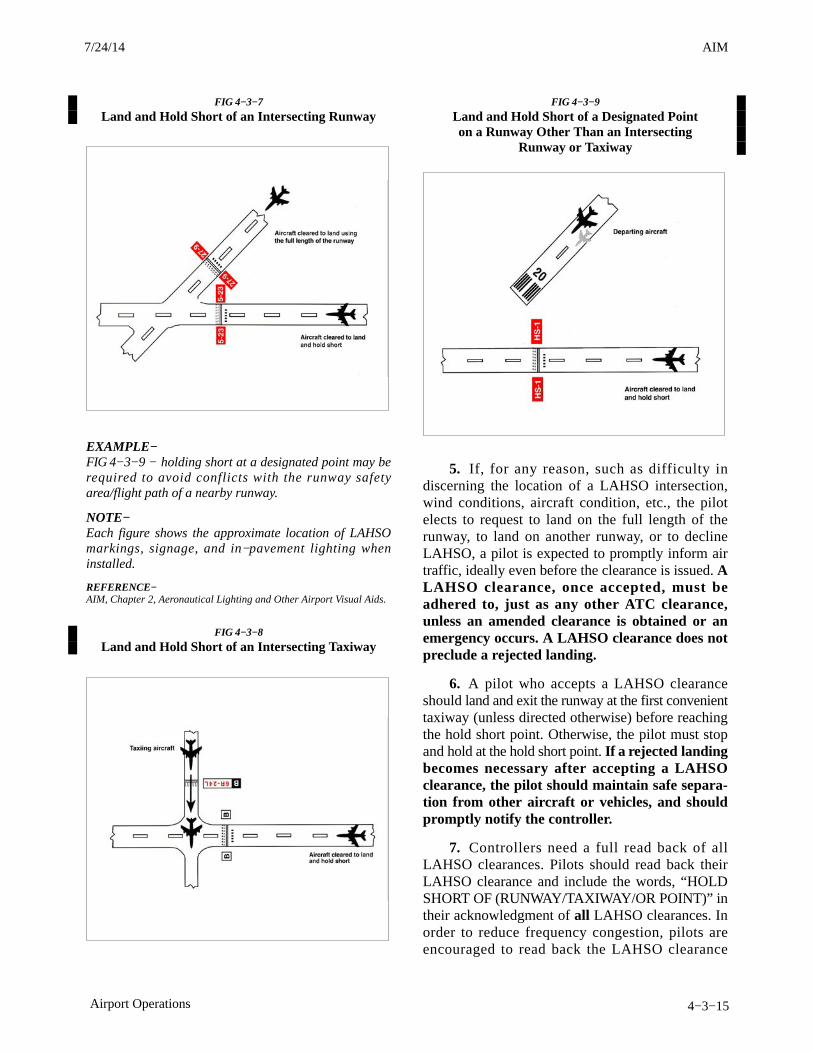
AIM4/3/14
4−3−15Airport Operations
FIG 4−3−7
Land and Hold Short of an Intersecting Runway
EXAMPLE−FIG 4−3−9 − holding short at a designated point may berequired to avoid conflicts with the runway safetyarea/flight path of a nearby runway.
NOTE−Each figure shows the approximate location of LAHSOmarkings, signage, and in−pavement lighting wheninstalled.
REFERENCE−AIM, Chapter 2, Aeronautical Lighting and Other Airport Visual Aids.
FIG 4−3−8
Land and Hold Short of an Intersecting Taxiway
FIG 4−3−9
Land and Hold Short of a Designated Pointon a Runway Other Than an Intersecting
Runway or Taxiway
5. If, for any reason, such as difficulty indiscerning the location of a LAHSO intersection,wind conditions, aircraft condition, etc., the pilotelects to request to land on the full length of therunway, to land on another runway, or to declineLAHSO, a pilot is expected to promptly inform airtraffic, ideally even before the clearance is issued. ALAHSO clearance, once accepted, must beadhered to, just as any other ATC clearance,unless an amended clearance is obtained or anemergency occurs. A LAHSO clearance does notpreclude a rejected landing.
6. A pilot who accepts a LAHSO clearanceshould land and exit the runway at the first convenienttaxiway (unless directed otherwise) before reachingthe hold short point. Otherwise, the pilot must stopand hold at the hold short point. If a rejected landingbecomes necessary after accepting a LAHSOclearance, the pilot should maintain safe separa-tion from other aircraft or vehicles, and shouldpromptly notify the controller.
7. Controllers need a full read back of allLAHSO clearances. Pilots should read back theirLAHSO clearance and include the words, “HOLDSHORT OF (RUNWAY/TAXIWAY/OR POINT)” intheir acknowledgment of all LAHSO clearances. Inorder to reduce frequency congestion, pilots areencouraged to read back the LAHSO clearance
7/24/14 AIM
AIM 4/3/14
4−3−16 Airport Operations
without prompting. Don’t make the controller have toask for a read back!
c. LAHSO Situational Awareness
1. Situational awareness is vital to the successof LAHSO. Situational awareness starts with havingcurrent airport information in the cockpit, readilyaccessible to the pilot. (An airport diagram assistspilots in identifying their location on the airport, thusreducing requests for “progressive taxi instructions”from controllers.)
2. Situational awareness includes effectivepilot−controller radio communication. ATC expectspilots to specifically acknowledge and read back allLAHSO clearances as follows:
EXAMPLE−ATC: “(Aircraft ID) cleared to land runway six right, holdshort of taxiway bravo for crossing traffic (type aircraft).”Aircraft: “(Aircraft ID), wilco, cleared to land runway sixright to hold short of taxiway bravo.”ATC: “(Aircraft ID) cross runway six right at taxiwaybravo, landing aircraft will hold short.”Aircraft: “(Aircraft ID), wilco, cross runway six right atbravo, landing traffic (type aircraft) to hold.”
3. For those airplanes flown with two crew-members, effective intra−cockpit communicationbetween cockpit crewmembers is also critical. Therehave been several instances where the pilot workingthe radios accepted a LAHSO clearance but thensimply forgot to tell the pilot flying the aircraft.
4. Situational awareness also includes a thor-ough understanding of the airport markings, signage,and lighting associated with LAHSO. These visualaids consist of a three−part system of yellowhold−short markings, red and white signage and,in certain cases, in−pavement lighting. Visual aidsassist the pilot in determining where to hold short.FIG 4−3−7, FIG 4−3−8, FIG 4−3−9 depict how thesemarkings, signage, and lighting combinations willappear once installed. Pilots are cautioned that not allairports conducting LAHSO have installed any or allof the above markings, signage, or lighting.
5. Pilots should only receive a LAHSOclearance when there is a minimum ceiling of1,000 feet and 3 statute miles visibility. The intent ofhaving “basic” VFR weather conditions is to allowpilots to maintain visual contact with other aircraftand ground vehicle operations. Pilots should consider
the effects of prevailing inflight visibility (such aslanding into the sun) and how it may affect overallsituational awareness. Additionally, surface vehiclesand aircraft being taxied by maintenance personnelmay also be participating in LAHSO, especially inthose operations that involve crossing an activerunway.
4−3−12. Low Approach
a. A low approach (sometimes referred to as a lowpass) is the go−around maneuver following anapproach. Instead of landing or making a touch−and−go, a pilot may wish to go around (low approach) inorder to expedite a particular operation (a series ofpractice instrument approaches is an example of suchan operation). Unless otherwise authorized by ATC,the low approach should be made straight ahead, withno turns or climb made until the pilot has made athorough visual check for other aircraft in the area.
b. When operating within a Class B, Class C, andClass D surface area, a pilot intending to make a lowapproach should contact the tower for approval. Thisrequest should be made prior to starting the finalapproach.
c. When operating to an airport, not within aClass B, Class C, and Class D surface area, a pilotintending to make a low approach should, prior toleaving the final approach fix inbound (nonprecisionapproach) or the outer marker or fix used in lieu of theouter marker inbound (precision approach), so advisethe FSS, UNICOM, or make a broadcast asappropriate.
REFERENCE−AIM, Traffic Advisory Practices at Airports Without Operating ControlTowers, Paragraph 4−1−9.
4−3−13. Traffic Control Light Signals
a. The following procedures are used by ATCTs inthe control of aircraft, ground vehicles, equipment,and personnel not equipped with radio. These sameprocedures will be used to control aircraft, groundvehicles, equipment, and personnel equipped withradio if radio contact cannot be established. ATCpersonnel use a directive traffic control signal whichemits an intense narrow light beam of a selected color(either red, white, or green) when controlling trafficby light signals.
3/15/077110.65R CHG 2AIM 7/24/14

AIM4/3/14
4−3−17Airport Operations
b. Although the traffic signal light offers theadvantage that some control may be exercised overnonradio equipped aircraft, pilots should be cogni-zant of the disadvantages which are:
1. Pilots may not be looking at the control towerat the time a signal is directed toward their aircraft.
2. The directions transmitted by a light signalare very limited since only approval or disapproval ofa pilot’s anticipated actions may be transmitted. Nosupplement or explanatory information may betransmitted except by the use of the “GeneralWarning Signal” which advises the pilot to be on thealert.
c. Between sunset and sunrise, a pilot wishing toattract the attention of the control tower should turnon a landing light and taxi the aircraft into a position,clear of the active runway, so that light is visible to thetower. The landing light should remain on untilappropriate signals are received from the tower.
d. Air Traffic Control Tower Light Gun Signals.(See TBL 4−3−1.)
e. During daylight hours, acknowledge towertransmissions or light signals by moving the aileronsor rudder. At night, acknowledge by blinking thelanding or navigation lights. If radio malfunctionoccurs after departing the parking area, watch thetower for light signals or monitor tower frequency.
TBL 4−3−1
Air Traffic Control Tower Light Gun Signals
Meaning
Color and Type of SignalMovement of Vehicles,
Equipment and Personnel Aircraft on the Ground Aircraft in Flight
Steady green Cleared to cross, proceed or go Cleared for takeoff Cleared to land
Flashing green Not applicable Cleared for taxi Return for landing (to befollowed by steady green at theproper time)
Steady red STOP STOP Give way to other aircraft andcontinue circling
Flashing red Clear the taxiway/runway Taxi clear of the runway in use Airport unsafe, do not land
Flashing white Return to starting point on airport Return to starting point on airport Not applicable
Alternating red and green Exercise extreme caution Exercise extreme caution Exercise extreme caution
4−3−14. Communications
a. Pilots of departing aircraft should communicatewith the control tower on the appropriate groundcontrol/clearance delivery frequency prior to startingengines to receive engine start time, taxi and/orclearance information. Unless otherwise advised bythe tower, remain on that frequency during taxiingand runup, then change to local control frequencywhen ready to request takeoff clearance.NOTE−Pilots are encouraged to monitor the local tower frequencyas soon as practical consistent with other ATCrequirements.REFERENCE−AIM, Automatic Terminal Information Service (ATIS),Paragraph 4−1−13.
b. The tower controller will consider that pilots ofturbine−powered aircraft are ready for takeoff whenthey reach the runway or warm−up block unlessadvised otherwise.
c. The majority of ground control frequencies arein the 121.6−121.9 MHz bandwidth. Ground controlfrequencies are provided to eliminate frequencycongestion on the tower (local control) frequency andare limited to communications between the tower andaircraft on the ground and between the tower andutility vehicles on the airport, provide a clear VHFchannel for arriving and departing aircraft. They areused for issuance of taxi information, clearances, andother necessary contacts between the tower andaircraft or other vehicles operated on the airport. Apilot who has just landed should not change from thetower frequency to the ground control frequency untildirected to do so by the controller. Normally, only oneground control frequency is assigned at an airport;however, at locations where the amount of traffic sowarrants, a second ground control frequency and/oranother frequency designated as a clearance deliveryfrequency, may be assigned.
7/24/14 AIM
AIM 4/3/14
4−3−18 Airport Operations
d. A controller may omit the ground or localcontrol frequency if the controller believes the pilotknows which frequency is in use. If the groundcontrol frequency is in the 121 MHz bandwidth thecontroller may omit the numbers preceding thedecimal point; e.g., 121.7, “CONTACT GROUNDPOINT SEVEN.” However, if any doubt exists as towhat frequency is in use, the pilot should promptlyrequest the controller to provide that information.
e. Controllers will normally avoid issuing a radiofrequency change to helicopters, known to besingle−piloted, which are hovering, air taxiing, orflying near the ground. At times, it may be necessaryfor pilots to alert ATC regarding single pilotoperations to minimize delay of essential ATCcommunications. Whenever possible, ATC instruc-tions will be relayed through the frequency beingmonitored until a frequency change can beaccomplished. You must promptly advise ATC if youare unable to comply with a frequency change. Also,you should advise ATC if you must land toaccomplish the frequency change unless it is clear thelanding will have no impact on other air traffic;e.g., on a taxiway or in a helicopter operating area.
4−3−15. Gate Holding Due to DepartureDelays
a. Pilots should contact ground control orclearance delivery prior to starting engines as gatehold procedures will be in effect whenever departuredelays exceed or are anticipated to exceed15 minutes. The sequence for departure will bemaintained in accordance with initial call up unlessmodified by flow control restrictions. Pilots shouldmonitor the ground control or clearance deliveryfrequency for engine startup advisories or newproposed start time if the delay changes.
b. The tower controller will consider that pilots ofturbine−powered aircraft are ready for takeoff whenthey reach the runway or warm−up block unlessadvised otherwise.
4−3−16. VFR Flights in Terminal Areas
Use reasonable restraint in exercising the prerogativeof VFR flight, especially in terminal areas. Theweather minimums and distances from clouds areminimums. Giving yourself a greater margin inspecific instances is just good judgment.
a. Approach Area. Conducting a VFR operationin a Class B, Class C, Class D, and Class E surfacearea when the official visibility is 3 or 4 miles is notprohibited, but good judgment would dictate that youkeep out of the approach area.
b. Reduced Visibility. It has always been recog-nized that precipitation reduces forward visibility.Consequently, although again it may be perfectlylegal to cancel your IFR flight plan at any time youcan proceed VFR, it is good practice, whenprecipitation is occurring, to continue IFR operationinto a terminal area until you are reasonably close toyour destination.
c. Simulated Instrument Flights. In conductingsimulated instrument flights, be sure that the weatheris good enough to compensate for the restrictedvisibility of the safety pilot and your greaterconcentration on your flight instruments. Giveyourself a little greater margin when your flight planlies in or near a busy airway or close to an airport.
4−3−17. VFR Helicopter Operations atControlled Airports
a. General.
1. The following ATC procedures and phraseol-ogies recognize the unique capabilities of helicoptersand were developed to improve service to all users.Helicopter design characteristics and user needs oftenrequire operations from movement areas andnonmovement areas within the airport boundary. Inorder for ATC to properly apply these procedures, itis essential that pilots familiarize themselves with thelocal operations and make it known to controllerswhen additional instructions are necessary.
2. Insofar as possible, helicopter operations willbe instructed to avoid the flow of fixed−wing aircraftto minimize overall delays; however, there will bemany situations where faster/larger helicopters maybe integrated with fixed−wing aircraft for the benefitof all concerned. Examples would include IFRflights, avoidance of noise sensitive areas, or use ofrunways/taxiways to minimize the hazardous effectsof rotor downwash in congested areas.
3. Because helicopter pilots are intimatelyfamiliar with the effects of rotor downwash, they arebest qualified to determine if a given operation can beconducted safely. Accordingly, the pilot has the finalauthority with respect to the specific airspeed/altitude
3/15/077110.65R CHG 2AIM 7/24/14

AIM4/3/14
4−3−19Airport Operations
combinations. ATC clearances are in no way intendedto place the helicopter in a hazardous position. It isexpected that pilots will advise ATC if a specificclearance will cause undue hazards to persons orproperty.
b. Controllers normally limit ATC ground serviceand instruction to movement areas; therefore,operations from nonmovement areas are conducted atpilot discretion and should be based on local policies,procedures, or letters of agreement. In order tomaximize the flexibility of helicopter operations, it isnecessary to rely heavily on sound pilot judgment.For example, hazards such as debris, obstructions,vehicles, or personnel must be recognized by thepilot, and action should be taken as necessary to avoidsuch hazards. Taxi, hover taxi, and air taxi operationsare considered to be ground movements. Helicoptersconducting such operations are expected to adhere tothe same conditions, requirements, and practices asapply to other ground taxiing and ATC procedures inthe AIM.
1. The phraseology taxi is used when it isintended or expected that the helicopter will taxi onthe airport surface, either via taxiways or otherprescribed routes. Taxi is used primarily forhelicopters equipped with wheels or in response to apilot request. Preference should be given to thisprocedure whenever it is necessary to minimizeeffects of rotor downwash.
2. Pilots may request a hover taxi when slowforward movement is desired or when it may beappropriate to move very short distances. Pilotsshould avoid this procedure if rotor downwash islikely to cause damage to parked aircraft or if blowingdust/snow could obscure visibility. If it is necessaryto operate above 25 feet AGL when hover taxiing, thepilot should initiate a request to ATC.
3. Air taxi is the preferred method for helicopterground movements on airports provided groundoperations and conditions permit. Unless otherwiserequested or instructed, pilots are expected to remainbelow 100 feet AGL. However, if a higher thannormal airspeed or altitude is desired, the requestshould be made prior to lift−off. The pilot is solelyresponsible for selecting a safe airspeed for thealtitude/operation being conducted. Use of air taxienables the pilot to proceed at an optimumairspeed/altitude, minimize downwash effect, con-serve fuel, and expedite movement from one point to
another. Helicopters should avoid overflight of otheraircraft, vehicles, and personnel during air−taxioperations. Caution must be exercised concerningactive runways and pilots must be certain that air taxiinstructions are understood. Special precautions maybe necessary at unfamiliar airports or airports withmultiple/intersecting active runways. The taxiprocedures given in Paragraph 4−3−18, Taxiing,Paragraph 4−3−19, Taxi During Low Visibility, andParagraph 4−3−20, Exiting the Runway AfterLanding, also apply.
REFERENCE−Pilot/Controller Glossary Term− Taxi.Pilot/Controller Glossary Term− Hover Taxi.Pilot/Controller Glossary Term− Air Taxi.
c. Takeoff and Landing Procedures.
1. Helicopter operations may be conductedfrom a runway, taxiway, portion of a landing strip, orany clear area which could be used as a landing sitesuch as the scene of an accident, a construction site,or the roof of a building. The terms used to describedesignated areas from which helicopters operate are:movement area, landing/takeoff area, apron/ramp,heliport and helipad (See Pilot/Controller Glossary).These areas may be improved or unimproved andmay be separate from or located on an airport/heliport. ATC will issue takeoff clearances frommovement areas other than active runways, or indiverse directions from active runways, withadditional instructions as necessary. Wheneverpossible, takeoff clearance will be issued in lieu ofextended hover/air taxi operations. Phraseology willbe “CLEARED FOR TAKEOFF FROM (taxiway,helipad, runway number, etc.), MAKE RIGHT/LEFT TURN FOR (direction, heading, NAVAIDradial) DEPARTURE/DEPARTURE ROUTE (num-ber, name, etc.).” Unless requested by the pilot,downwind takeoffs will not be issued if the tailwindexceeds 5 knots.
2. Pilots should be alert to wind information aswell as to wind indications in the vicinity of thehelicopter. ATC should be advised of the intendedmethod of departing. A pilot request to takeoff in agiven direction indicates that the pilot is willing toaccept the wind condition and controllers will honorthe request if traffic permits. Departure points couldbe a significant distance from the control tower andit may be difficult or impossible for the controller todetermine the helicopter’s relative position to thewind.
7/24/14 AIM
AIM 4/3/14
4−3−20 Airport Operations
3. If takeoff is requested from nonmovementareas, an area not authorized for helicopter use, anarea not visible from the tower, an unlighted area atnight, or an area off the airport, the phraseology“DEPARTURE FROM (requested location) WILLBE AT YOUR OWN RISK (additional instructions,as necessary). USE CAUTION (if applicable).” Thepilot is responsible for operating in a safe manner andshould exercise due caution.
4. Similar phraseology is used for helicopterlanding operations. Every effort will be made topermit helicopters to proceed direct and land as nearas possible to their final destination on the airport.Traffic density, the need for detailed taxiinginstructions, frequency congestion, or other factorsmay affect the extent to which service can beexpedited. As with ground movement operations, ahigh degree of pilot/controller cooperation andcommunication is necessary to achieve safe andefficient operations.
4−3−18. Taxiing
a. General. Approval must be obtained prior tomoving an aircraft or vehicle onto the movement areaduring the hours an Airport Traffic Control Tower isin operation.
1. Always state your position on the airportwhen calling the tower for taxi instructions.
2. The movement area is normally described inlocal bulletins issued by the airport manager orcontrol tower. These bulletins may be found in FSSs,fixed base operators offices, air carrier offices, andoperations offices.
3. The control tower also issues bulletinsdescribing areas where they cannot provide ATCservice due to nonvisibility or other reasons.
4. A clearance must be obtained prior to taxiingon a runway, taking off, or landing during the hoursan Airport Traffic Control Tower is in operation.
5. A clearance must be obtained prior tocrossing any runway. ATC will issue an explicitclearance for all runway crossings.
6. When assigned a takeoff runway, ATC willfirst specify the runway, issue taxi instructions, andstate any hold short instructions or runway crossingclearances if the taxi route will cross a runway. This
does not authorize the aircraft to “enter” or “cross”the assigned departure runway at any point. In orderto preclude misunderstandings in radio communica-tions, ATC will not use the word “cleared” inconjunction with authorization for aircraft to taxi.
7. When issuing taxi instructions to any pointother than an assigned takeoff runway, ATC willspecify the point to taxi to, issue taxi instructions, andstate any hold short instructions or runway crossingclearances if the taxi route will cross a runway.
NOTE−ATC is required to obtain a readback from the pilot of allrunway hold short instructions.
8. If a pilot is expected to hold short of a runwayapproach (“APPCH”) area or ILS holding position(see FIG 2−3−15, Taxiways Located in RunwayApproach Area), ATC will issue instructions.
9. When taxi instructions are received from thecontroller, pilots should always read back:
(a) The runway assignment.
(b) Any clearance to enter a specific runway.
(c) Any instruction to hold short of a specificrunway or line up and wait.
Controllers are required to request a readback ofrunway hold short assignment when it is not receivedfrom the pilot/vehicle.
b. ATC clearances or instructions pertaining totaxiing are predicated on known traffic and knownphysical airport conditions. Therefore, it is importantthat pilots clearly understand the clearance orinstruction. Although an ATC clearance is issued fortaxiing purposes, when operating in accordance withthe CFRs, it is the responsibility of the pilot to avoidcollision with other aircraft. Since “the pilot−in−com-mand of an aircraft is directly responsible for, and isthe final authority as to, the operation of that aircraft”the pilot should obtain clarification of any clearanceor instruction which is not understood.
REFERENCE−AIM, General, Paragraph 7−3−1.
1. Good operating practice dictates that pilotsacknowledge all runway crossing, hold short, ortakeoff clearances unless there is some misunder-standing, at which time the pilot should query thecontroller until the clearance is understood.
3/15/077110.65R CHG 2AIM 7/24/14

AIM4/3/14
4−3−21Airport Operations
NOTE−Air traffic controllers are required to obtain from the pilota readback of all runway hold short instructions.
2. Pilots operating a single pilot aircraft shouldmonitor only assigned ATC communications afterbeing cleared onto the active runway for departure.Single pilot aircraft should not monitor other thanATC communications until flight from Class B,Class C, or Class D surface area is completed. Thissame procedure should be practiced from after receiptof the clearance for landing until the landing and taxiactivities are complete. Proper effective scanning forother aircraft, surface vehicles, or other objectsshould be continuously exercised in all cases.
3. If the pilot is unfamiliar with the airport or forany reason confusion exists as to the correct taxirouting, a request may be made for progressive taxiinstructions which include step−by−step routingdirections. Progressive instructions may also beissued if the controller deems it necessary due totraffic or field conditions (for example, constructionor closed taxiways).
c. At those airports where the U.S. Governmentoperates the control tower and ATC has authorizednoncompliance with the requirement for two−wayradio communications while operating within theClass B, Class C, or Class D surface area, or at thoseairports where the U.S. Government does not operatethe control tower and radio communications cannotbe established, pilots must obtain a clearance byvisual light signal prior to taxiing on a runway andprior to takeoff and landing.
d. The following phraseologies and proceduresare used in radiotelephone communications withaeronautical ground stations.
1. Request for taxi instructions prior todeparture. State your aircraft identification, loca-tion, type of operation planned (VFR or IFR), and thepoint of first intended landing.
EXAMPLE−Aircraft: “Washington ground, Beechcraft One Three OneFive Niner at hangar eight, ready to taxi, I−F−R toChicago.” Tower: “Beechcraft one three one five niner, Washingtonground, runway two seven, taxi via taxiways Charlie andDelta, hold short of runway three three left.”
Aircraft: “Beechcraft One Three One Five Niner, holdshort of runway three three left.”
2. Receipt of ATC clearance. ARTCC clear-ances are relayed to pilots by airport trafficcontrollers in the following manner.
EXAMPLE−Tower: “Beechcraft One Three One Five Niner, cleared tothe Chicago Midway Airport via Victor Eight, maintaineight thousand.”
Aircraft: “Beechcraft One Three One Five Niner, clearedto the Chicago Midway Airport via Victor Eight, maintaineight thousand.”
NOTE−Normally, an ATC IFR clearance is relayed to a pilot by theground controller. At busy locations, however, pilots maybe instructed by the ground controller to “contactclearance delivery” on a frequency designated for thispurpose. No surveillance or control over the movement oftraffic is exercised by this position of operation.
3. Request for taxi instructions after landing.State your aircraft identification, location, and thatyou request taxi instructions.
EXAMPLE−Aircraft: “Dulles ground, Beechcraft One Four Two SixOne clearing runway one right on taxiway echo three,request clearance to Page.”
Tower: “Beechcraft One Four Two Six One, Dullesground, taxi to Page via taxiways echo three, echo one, andecho niner.”
or
Aircraft: “Orlando ground, Beechcraft One Four Two SixOne clearing runway one eight left at taxiway bravo three,request clearance to Page.”
Tower: “Beechcraft One Four Two Six One, Orlandoground, hold short of runway one eight right.”
Aircraft: “Beechcraft One Four Two Six One, hold shortof runway one eight right.”
4−3−19. Taxi During Low Visibility
a. Pilots and aircraft operators should be constant-ly aware that during certain low visibility conditionsthe movement of aircraft and vehicles on airports maynot be visible to the tower controller. This mayprevent visual confirmation of an aircraft’s adherenceto taxi instructions.
7/24/14 AIM
AIM 4/3/14
4−3−22 Airport Operations
b. Of vital importance is the need for pilots tonotify the controller when difficulties are encoun-tered or at the first indication of becomingdisoriented. Pilots should proceed with extremecaution when taxiing toward the sun. When visiondifficulties are encountered pilots shouldimmediately inform the controller.
c. Advisory Circular 120−57, Surface MovementGuidance and Control System, commonly known asSMGCS (pronounced “SMIGS”) requires a lowvisibility taxi plan for any airport which has takeoffor landing operations in less than 1,200 feet runwayvisual range (RVR) visibility conditions. These plans,which affect aircrew and vehicle operators, mayincorporate additional lighting, markings, andprocedures to control airport surface traffic. Theywill be addressed at two levels; operations less than1,200 feet RVR to 600 feet RVR and operations lessthan 600 feet RVR.
NOTE−Specific lighting systems and surface markings may befound in paragraph 2−1−11, Taxiway Lights, andparagraph 2−3−4, Taxiway Markings.
d. When low visibility conditions exist, pilotsshould focus their entire attention on the safeoperation of the aircraft while it is moving. Checklistsand nonessential communication should be withhelduntil the aircraft is stopped and the brakes set.
4−3−20. Exiting the Runway After Landing
The following procedures must be followed afterlanding and reaching taxi speed.
a. Exit the runway without delay at the firstavailable taxiway or on a taxiway as instructed byATC. Pilots must not exit the landing runway ontoanother runway unless authorized by ATC. Atairports with an operating control tower, pilots shouldnot stop or reverse course on the runway without firstobtaining ATC approval.
b. Taxi clear of the runway unless otherwisedirected by ATC. An aircraft is considered clear of therunway when all parts of the aircraft are past therunway edge and there are no restrictions to itscontinued movement beyond the runway holdingposition markings. In the absence of ATC instruc-tions, the pilot is expected to taxi clear of the landingrunway by taxiing beyond the runway holdingposition markings associated with the landing
runway, even if that requires the aircraft to protrudeinto or cross another taxiway or ramp area. Once allparts of the aircraft have crossed the runway holdingposition markings, the pilot must hold unless furtherinstructions have been issued by ATC.
NOTE−1. The tower will issue the pilot instructions which willpermit the aircraft to enter another taxiway, runway, orramp area when required.
2. Guidance contained in subparagraphs a and b above isconsidered an integral part of the landing clearance andsatisfies the requirement of 14 CFR Section 91.129.
c. Immediately change to ground control fre-quency when advised by the tower and obtain a taxiclearance.
NOTE−1. The tower will issue instructions required to resolve anypotential conflictions with other ground traffic prior toadvising the pilot to contact ground control.
2. Ground control will issue taxi clearance to parking.That clearance does not authorize the aircraft to “enter”or “cross” any runways. Pilots not familiar with the taxiroute should request specific taxi instructions from ATC.
4−3−21. Practice Instrument Approaches
a. Various air traffic incidents have indicated thenecessity for adoption of measures to achieve moreorganized and controlled operations where practiceinstrument approaches are conducted. Practiceinstrument approaches are considered to be instru-ment approaches made by either a VFR aircraft not onan IFR flight plan or an aircraft on an IFR flight plan.To achieve this and thereby enhance air safety, it isAir Traffic’s policy to provide for separation of suchoperations at locations where approach controlfacilities are located and, as resources permit, atcertain other locations served by ARTCCs or parentapproach control facilities. Pilot requests to practiceinstrument approaches may be approved by ATCsubject to traffic and workload conditions. Pilotsshould anticipate that in some instances the controllermay find it necessary to deny approval or withdrawprevious approval when traffic conditions warrant. Itmust be clearly understood, however, that eventhough the controller may be providing separation,pilots on VFR flight plans are required to comply withbasic VFR weather minimums (14 CFR Sec-tion 91.155). Application of ATC procedures or anyaction taken by the controller to avoid trafficconflictions does not relieve IFR and VFR pilots of
3/15/077110.65R CHG 2AIM 7/24/14

AIM4/3/14
4−3−23Airport Operations
their responsibility to see−and−avoid other trafficwhile operating in VFR conditions (14 CFRSection 91.113). In addition to the normal IFRseparation minimums (which includes visual separa-tion) during VFR conditions, 500 feet verticalseparation may be applied between VFR aircraft andbetween a VFR aircraft and the IFR aircraft. Pilots noton IFR flight plans desiring practice instrumentapproaches should always state ‘practice’ whenmaking requests to ATC. Controllers will instructVFR aircraft requesting an instrument approach tomaintain VFR. This is to preclude misunderstandingsbetween the pilot and controller as to the status of theaircraft. If pilots wish to proceed in accordance withinstrument flight rules, they must specifically requestand obtain, an IFR clearance.
b. Before practicing an instrument approach,pilots should inform the approach control facility orthe tower of the type of practice approach they desireto make and how they intend to terminate it,i.e., full−stop landing, touch−and−go, or missed orlow approach maneuver. This information may befurnished progressively when conducting a series ofapproaches. Pilots on an IFR flight plan, who havemade a series of instrument approaches to full stoplandings should inform ATC when they make theirfinal landing. The controller will control flightspracticing instrument approaches so as to ensure thatthey do not disrupt the flow of arriving and departingitinerant IFR or VFR aircraft. The priority affordeditinerant aircraft over practice instrument approachesis not intended to be so rigidly applied that it causesgrossly inefficient application of services. Aminimum delay to itinerant traffic may be appropriateto allow an aircraft practicing an approach tocomplete that approach.
NOTE−A clearance to land means that appropriate separation onthe landing runway will be ensured. A landing clearancedoes not relieve the pilot from compliance with anypreviously issued restriction.
c. At airports without a tower, pilots wishing tomake practice instrument approaches should notifythe facility having control jurisdiction of the desiredapproach as indicated on the approach chart. Allapproach control facilities and ARTCCs are requiredto publish a Letter to Airmen depicting those airportswhere they provide standard separation to both VFRand IFR aircraft conducting practice instrumentapproaches.
d. The controller will provide approved separationbetween both VFR and IFR aircraft when authoriza-tion is granted to make practice approaches to airportswhere an approach control facility is located and tocertain other airports served by approach control oran ARTCC. Controller responsibility for separationof VFR aircraft begins at the point where theapproach clearance becomes effective, or when theaircraft enters Class B or Class C airspace, or a TRSA,whichever comes first.
e. VFR aircraft practicing instrument approachesare not automatically authorized to execute themissed approach procedure. This authorization mustbe specifically requested by the pilot and approved bythe controller. Separation will not be provided unlessthe missed approach has been approved by ATC.
f. Except in an emergency, aircraft cleared topractice instrument approaches must not deviate fromthe approved procedure until cleared to do so by thecontroller.
g. At radar approach control locations when a fullapproach procedure (procedure turn, etc.,) cannot beapproved, pilots should expect to be vectored to afinal approach course for a practice instrumentapproach which is compatible with the generaldirection of traffic at that airport.
h. When granting approval for a practiceinstrument approach, the controller will usually askthe pilot to report to the tower prior to or over the finalapproach fix inbound (nonprecision approaches) orover the outer marker or fix used in lieu of the outermarker inbound (precision approaches).
i. When authorization is granted to conductpractice instrument approaches to an airport with atower, but where approved standard separation is notprovided to aircraft conducting practice instrumentapproaches, the tower will approve the practiceapproach, instruct the aircraft to maintain VFR andissue traffic information, as required.
j. When an aircraft notifies a FSS providing LocalAirport Advisory to the airport concerned of theintent to conduct a practice instrument approach andwhether or not separation is to be provided, the pilotwill be instructed to contact the appropriate facilityon a specified frequency prior to initiating theapproach. At airports where separation is notprovided, the FSS will acknowledge the message andissue known traffic information but will neitherapprove or disapprove the approach.
7/24/14 AIM
AIM 4/3/14
4−3−24 Airport Operations
k. Pilots conducting practice instrumentapproaches should be particularly alert for otheraircraft operating in the local traffic pattern or inproximity to the airport.
4−3−22. Option Approach
The “Cleared for the Option” procedure will permitan instructor, flight examiner or pilot the option tomake a touch−and−go, low approach, missedapproach, stop−and−go, or full stop landing. Thisprocedure can be very beneficial in a trainingsituation in that neither the student pilot nor examineewould know what maneuver would be accomplished.The pilot should make a request for this procedurepassing the final approach fix inbound on aninstrument approach or entering downwind for a VFRtraffic pattern. The advantages of this procedure as atraining aid are that it enables an instructor orexaminer to obtain the reaction of a trainee orexaminee under changing conditions, the pilot wouldnot have to discontinue an approach in the middle ofthe procedure due to student error or pilot proficiencyrequirements, and finally it allows more flexibilityand economy in training programs. This procedurewill only be used at those locations with anoperational control tower and will be subject to ATCapproval.
4−3−23. Use of Aircraft Lights
a. Aircraft position lights are required to be lightedon aircraft operated on the surface and in flight fromsunset to sunrise. In addition, aircraft equipped withan anti−collision light system are required to operatethat light system during all types of operations (dayand night). However, during any adverse meteorolog-ical conditions, the pilot−in−command maydetermine that the anti−collision lights should beturned off when their light output would constitute ahazard to safety (14 CFR Section 91.209).Supplementary strobe lights should be turned off onthe ground when they adversely affect groundpersonnel or other pilots, and in flight when there areadverse reflection from clouds.
b. An aircraft anti−collision light system can useone or more rotating beacons and/or strobe lights, becolored either red or white, and have different (higherthan minimum) intensities when compared to otheraircraft. Many aircraft have both a rotating beaconand a strobe light system.
c. The FAA has a voluntary pilot safety program,Operation Lights On, to enhance the see−and−avoidconcept. Pilots are encouraged to turn on their landinglights during takeoff; i.e., either after takeoffclearance has been received or when beginningtakeoff roll. Pilots are further encouraged to turn ontheir landing lights when operating below10,000 feet, day or night, especially when operatingwithin 10 miles of any airport, or in conditions ofreduced visibility and in areas where flocks of birdsmay be expected, i.e., coastal areas, lake areas,around refuse dumps, etc. Although turning onaircraft lights does enhance the see−and−avoidconcept, pilots should not become complacent aboutkeeping a sharp lookout for other aircraft. Not allaircraft are equipped with lights and some pilots maynot have their lights turned on. Aircraft manufactur-er’s recommendations for operation of landing lightsand electrical systems should be observed.
d. Prop and jet blast forces generated by largeaircraft have overturned or damaged several smalleraircraft taxiing behind them. To avoid similar results,and in the interest of preventing upsets and injuries toground personnel from such forces, the FAArecommends that air carriers and commercialoperators turn on their rotating beacons anytime theiraircraft engines are in operation. General aviationpilots using rotating beacon equipped aircraft are alsoencouraged to participate in this program which isdesigned to alert others to the potential hazard. Sincethis is a voluntary program, exercise caution and donot rely solely on the rotating beacon as an indicationthat aircraft engines are in operation.
e. Prior to commencing taxi, it is recommended toturn on navigation, position, anti-collision, and logolights (if equipped). To signal intent to other pilots,consider turning on the taxi light when the aircraft ismoving or intending to move on the ground, andturning it off when stopped or yielding to otherground traffic. Strobe lights should not be illuminatedduring taxi if they will adversely affect the vision ofother pilots or ground personnel.
f. At the discretion of the pilot-in-command, allexterior lights should be illuminated when taxiing onor across any runway. This increases the conspicu-ousness of the aircraft to controllers and other pilotsapproaching to land, taxiing, or crossing the runway.Pilots should comply with any equipment operatinglimitations and consider the effects of landing andstrobe lights on other aircraft in their vicinity.
3/15/077110.65R CHG 2AIM 7/24/14
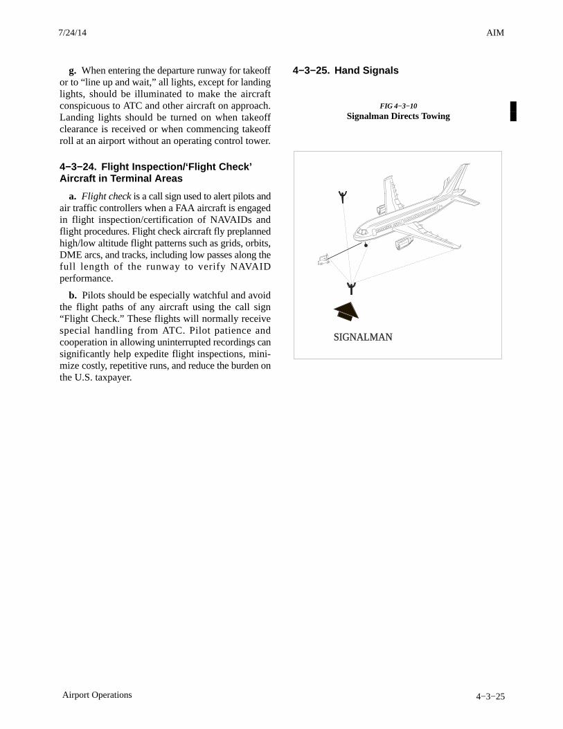
AIM4/3/14
4−3−25Airport Operations
g. When entering the departure runway for takeoffor to “line up and wait,” all lights, except for landinglights, should be illuminated to make the aircraftconspicuous to ATC and other aircraft on approach.Landing lights should be turned on when takeoffclearance is received or when commencing takeoffroll at an airport without an operating control tower.
4−3−24. Flight Inspection/‘Flight Check’Aircraft in Terminal Areas
a. Flight check is a call sign used to alert pilots andair traffic controllers when a FAA aircraft is engagedin flight inspection/certification of NAVAIDs andflight procedures. Flight check aircraft fly preplannedhigh/low altitude flight patterns such as grids, orbits,DME arcs, and tracks, including low passes along thefull length of the runway to verify NAVAIDperformance.
b. Pilots should be especially watchful and avoidthe flight paths of any aircraft using the call sign“Flight Check.” These flights will normally receivespecial handling from ATC. Pilot patience andcooperation in allowing uninterrupted recordings cansignificantly help expedite flight inspections, mini-mize costly, repetitive runs, and reduce the burden onthe U.S. taxpayer.
4−3−25. Hand Signals
FIG 4−3−10
Signalman Directs Towing
SIGNALMAN
7/24/14 AIM

AIM 4/3/14
4−3−26 Airport Operations
FIG 4−3−11
Signalman’s Position
SIGNALMAN
FIG 4−3−12
All Clear(O.K.)
FIG 4−3−13
Start Engine
POINTTOENGINETO BESTARTED
FIG 4−3−14
Pull Chocks
3/15/077110.65R CHG 2AIM 7/24/14
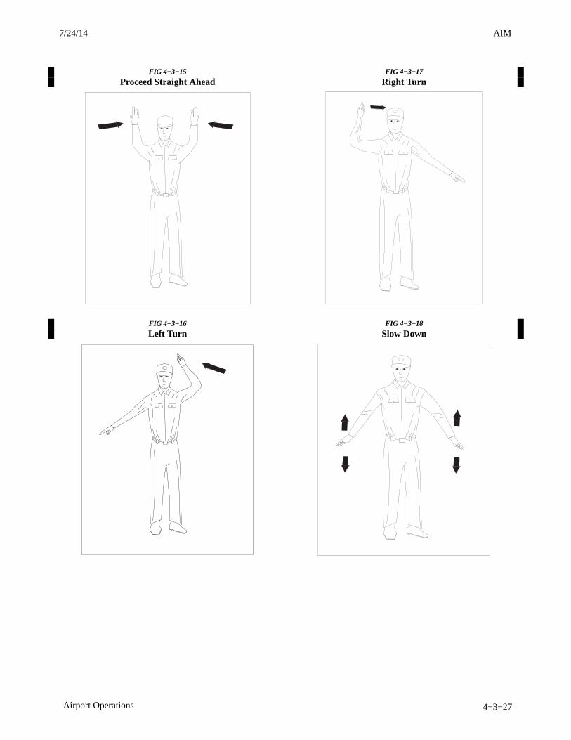
AIM4/3/14
4−3−27Airport Operations
FIG 4−3−15
Proceed Straight Ahead
FIG 4−3−16
Left Turn
FIG 4−3−17
Right Turn
FIG 4−3−18
Slow Down
7/24/14 AIM
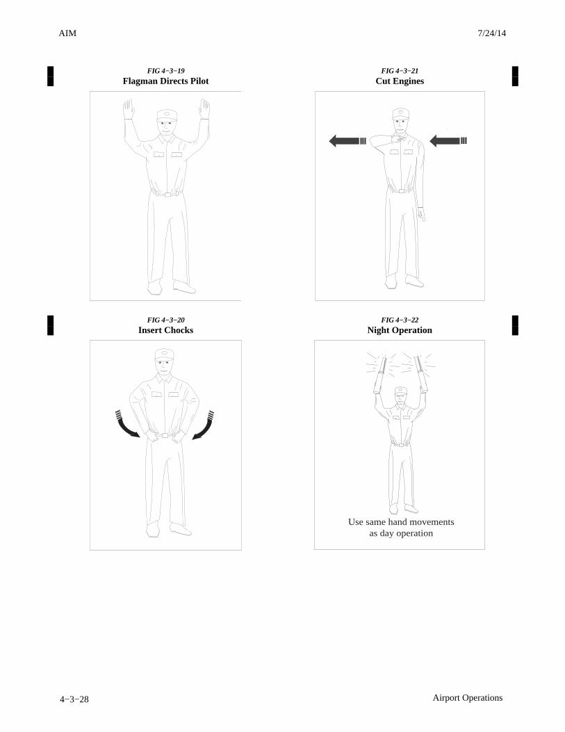
AIM 4/3/14
4−3−28 Airport Operations
FIG 4−3−19
Flagman Directs Pilot
FIG 4−3−20
Insert Chocks
FIG 4−3−21
Cut Engines
FIG 4−3−22
Night Operation
Use same hand movementsas day operation
3/15/077110.65R CHG 2AIM 7/24/14
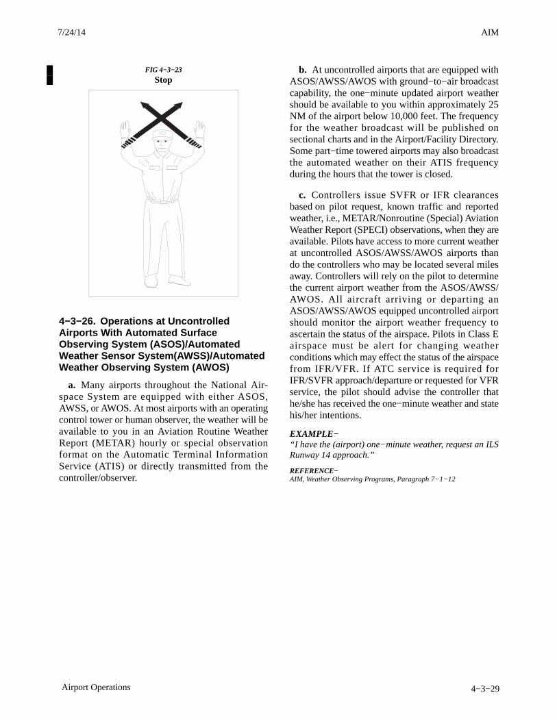
AIM4/3/14
4−3−29Airport Operations
FIG 4−3−23
Stop
4−3−26. Operations at UncontrolledAirports With Automated SurfaceObserving System (ASOS)/AutomatedWeather Sensor System(AWSS)/AutomatedWeather Observing System (AWOS)
a. Many airports throughout the National Air-space System are equipped with either ASOS,AWSS, or AWOS. At most airports with an operatingcontrol tower or human observer, the weather will beavailable to you in an Aviation Routine WeatherReport (METAR) hourly or special observationformat on the Automatic Terminal InformationService (ATIS) or directly transmitted from thecontroller/observer.
b. At uncontrolled airports that are equipped withASOS/AWSS/AWOS with ground−to−air broadcastcapability, the one−minute updated airport weathershould be available to you within approximately 25NM of the airport below 10,000 feet. The frequencyfor the weather broadcast will be published onsectional charts and in the Airport/Facility Directory.Some part−time towered airports may also broadcastthe automated weather on their ATIS frequencyduring the hours that the tower is closed.
c. Controllers issue SVFR or IFR clearancesbased on pilot request, known traffic and reportedweather, i.e., METAR/Nonroutine (Special) AviationWeather Report (SPECI) observations, when they areavailable. Pilots have access to more current weatherat uncontrolled ASOS/AWSS/AWOS airports thando the controllers who may be located several milesaway. Controllers will rely on the pilot to determinethe current airport weather from the ASOS/AWSS/AWOS. All aircraft arriving or departing anASOS/AWSS/AWOS equipped uncontrolled airportshould monitor the airport weather frequency toascertain the status of the airspace. Pilots in Class Eairspace must be alert for changing weatherconditions which may effect the status of the airspacefrom IFR/VFR. If ATC service is required forIFR/SVFR approach/departure or requested for VFRservice, the pilot should advise the controller thathe/she has received the one−minute weather and statehis/her intentions.
EXAMPLE−“I have the (airport) one−minute weather, request an ILSRunway 14 approach.”
REFERENCE−AIM, Weather Observing Programs, Paragraph 7−1−12.
7/24/14 AIM

AIM4/3/14
4−5−13Surveillance Systems
indicated in FIG 4−5−4. TIS users must be alert toaltitude encoder malfunctions, as TIS has nomechanism to determine if client altitude reporting iscorrect. A failure of this nature will cause erroneousand possibly unpredictable TIS operation. If thismalfunction is suspected, confirmation of altitudereporting with ATC is suggested.
(c) Intruder Altitude Reporting. Intruderswithout altitude reporting capability will be dis-played without the accompanying altitude tag.Additionally, nonaltitude reporting intruders areassumed to be at the same altitude as the TIS client foralert computations. This helps to ensure that the pilotwill be alerted to all traffic under radar coverage, butthe actual altitude difference may be substantial.Therefore, visual acquisition may be difficult in thisinstance.
(d) Coverage Limitations. Since TIS isprovided by ground−based, secondary surveillanceradar, it is subject to all limitations of that radar. If anaircraft is not detected by the radar, it cannot bedisplayed on TIS. Examples of these limitations areas follows:
(1) TIS will typically be provided within55 NM of the radars depicted in FIG 4−5−5, TerminalMode S Radar Sites. This maximum range can varyby radar site and is always subject to “line of sight”limitations; the radar and data link signals will beblocked by obstructions, terrain, and curvature of theearth.
(2) TIS will be unavailable at low altitudesin many areas of the country, particularly inmountainous regions. Also, when flying near the“floor” of radar coverage in a particular area,intruders below the client aircraft may not be detectedby TIS.
(3) TIS will be temporarily disrupted whenflying directly over the radar site providing coverageif no adjacent site assumes the service. Aground−based radar, like a VOR or NDB, has a zenithcone, sometimes referred to as the cone of confusionor cone of silence. This is the area of ambiguitydirectly above the station where bearing informationis unreliable. The zenith cone setting for TIS is34 degrees: Any aircraft above that angle withrespect to the radar horizon will lose TIS coveragefrom that radar until it is below this 34 degree angle.The aircraft may not actually lose service in areas of
multiple radar coverage since an adjacent radar willprovide TIS. If no other TIS−capable radar isavailable, the “Good−bye” message will be receivedand TIS terminated until coverage is resumed.
(e) Intermittent Operations. TIS operationmay be intermittent during turns or other maneuver-ing, particularly if the transponder system does notinclude antenna diversity (antenna mounted on thetop and bottom of the aircraft). As in (d) above, TISis dependent on two−way, “line of sight” communica-tions between the aircraft and the Mode S radar.Whenever the structure of the client aircraft comesbetween the transponder antenna (usually located onthe underside of the aircraft) and the ground−basedradar antenna, the signal may be temporarilyinterrupted.
(f) TIS Predictive Algorithm. TIS informa-tion is collected one radar scan prior to the scanduring which the uplink occurs. Therefore, thesurveillance information is approximately 5 secondsold. In order to present the intruders in a “real time”position, TIS uses a “predictive algorithm” in itstracking software. This algorithm uses track historydata to extrapolate intruders to their expectedpositions consistent with the time of display in thecockpit. Occasionally, aircraft maneuvering willcause this algorithm to induce errors in the TISdisplay. These errors primarily affect relative bearinginformation; intruder distance and altitude willremain relatively accurate and may be used to assistin “see and avoid.” Some of the more commonexamples of these errors are as follows:
(1) When client or intruder aircraft maneu-ver excessively or abruptly, the tracking algorithmwill report incorrect horizontal position until themaneuvering aircraft stabilizes.
(2) When a rapidly closing intruder is on acourse that crosses the client at a shallow angle (eitherovertaking or head on) and either aircraft abruptlychanges course within ¼ NM, TIS will display theintruder on the opposite side of the client than itactually is.
These are relatively rare occurrences and will becorrected in a few radar scans once the course hasstabilized.
(g) Heading/Course Reference. Not all TISaircraft installations will have onboard headingreference information. In these installations, aircraftcourse reference to the TIS display is provided by the
AIM 4/3/14
4−5−14 Surveillance Systems
Mode S radar. The radar only determines groundtrack information and has no indication of the clientaircraft heading. In these installations, all intruderbearing information is referenced to ground track anddoes not account for wind correction. Additionally,since ground−based radar will require several scansto determine aircraft course following a coursechange, a lag in TIS display orientation (intruderaircraft bearing) will occur. As in (f) above, intruderdistance and altitude are still usable.
(h) Closely−Spaced Intruder Errors.When operating more than 30 NM from the Mode Ssensor, TIS forces any intruder within 3/8 NM of theTIS client to appear at the same horizontal position asthe client aircraft. Without this feature, TIS coulddisplay intruders in a manner confusing to the pilot incritical situations (e.g., a closely−spaced intruder thatis actually to the right of the client may appear on theTIS display to the left). At longer distances from theradar, TIS cannot accurately determine relativebearing/distance information on intruder aircraft thatare in close proximity to the client.
Because TIS uses a ground−based, rotating radar forsurveillance information, the accuracy of TIS data isdependent on the distance from the sensor (radar)providing the service. This is much the samephenomenon as experienced with ground−basednavigational aids, such as VOR or NDB. As distancefrom the radar increases, the accuracy of surveillancedecreases. Since TIS does not inform the pilot ofdistance from the Mode S radar, the pilot must assumethat any intruder appearing at the same position as theclient aircraft may actually be up to 3/8 NM away inany direction. Consistent with the operation of TIS,an alert on the display (regardless of distance from theradar) should stimulate an outside visual scan,intruder acquisition, and traffic avoidance based onoutside reference.
e. Reports of TIS Malfunctions
1. Users of TIS can render valuable assistance inthe early correction of malfunctions by reporting theirobservations of undesirable performance. Reportersshould identify the time of observation, location, typeand identity of aircraft, and describe the conditionobserved; the type of transponder processor, andsoftware in use can also be useful information. SinceTIS performance is monitored by maintenancepersonnel rather than ATC, it is suggested thatmalfunctions be reported by radio or telephone to thenearest Flight Service Station (FSS) facility.
4−5−7. Automatic DependentSurveillance−Broadcast (ADS−B) Services
a. Introduction
1. Automatic Dependent Surveillance−Broad-cast (ADS−B) is a surveillance technology beingdeployed throughout the NAS (see FIG 4−5−7). TheADS−B system is composed of aircraft avionics anda ground infrastructure. Onboard avionics determinethe position of the aircraft by using the GNSS andtransmit its position along with additional informa-tion about the aircraft to ground stations for use byATC and other ADS−B services. This information istransmitted at a rate of approximately once persecond.
2. In the United States, ADS−B equippedaircraft exchange information is on one of twofrequencies: 978 or 1090 MHz. The 1090 MHzfrequency is associated with Mode A, C, and Stransponder operations. 1090 MHz transponderswith integrated ADS−B functionality extend thetransponder message sets with additional ADS−Binformation. This additional information is knownas an “extended squitter” message and referred to as1090ES. ADS−B equipment operating on 978 MHzis known as the Universal Access Transceiver (UAT).
3/15/077110.65R CHG 2AIM 7/24/14
AIM4/3/14
4−5−17Surveillance Systems
2. Use of ADS−B radar services is limited to theservice volume of the GBT.
NOTE−The coverage volume of GBTs are limited to line−of−sight.
f. Reports of ADS−B Malfunctions
Users of ADS−B can provide valuable assistance inthe correction of malfunctions by reporting instancesof undesirable system performance. Reports shouldidentify the time of observation, location, type andidentity of aircraft, and describe the conditionobserved; the type of avionics system and its softwareversion in use should also be included. Since ADS−Bperformance is monitored by maintenance personnelrather than ATC, it is suggested that malfunctions bereported in any one of the following ways:
1. By radio or telephone to the nearest FlightService Station (FSS) facility.
2. By reporting the failure directly to the FAASafe Flight 21 program at 1−877−FLYADSB orhttp://www.adsb.gov.
4−5−8. Traffic Information Service−Broadcast (TIS−B)
TIS−B is the broadcast of ATC derived trafficinformation to ADS−B equipped (1090ES or UAT)aircraft from ground radio stations. The source of thistraffic information is derived from ground−based airtraffic surveillance radar sensors. TIS−B servicewill be available throughout the NAS where there areboth adequate surveillance coverage (radar) fromground sensors and adequate broadcast coveragefrom ADS−B ground radio stations. The quality levelof traffic information provided by TIS−B isdependent upon the number and type of groundsensors available as TIS−B sources and thetimeliness of the reported data.
a. TIS−B Requirements.
In order to receive TIS−B service, the followingconditions must exist:
1. Aircraft must be equipped with an ADS−Btransmitter/receiver or transceiver, and a cockpitdisplay of traffic information (CDTI).
2. Aircraft must fly within the coverage volumeof a compatible ground radio station that isconfigured for TIS−B uplinks. (Not all ground radio
stations provide TIS−B due to a lack of radarcoverage or because a radar feed is not available).
3. Aircraft must be within the coverage of anddetected by at least one ATC radar serving the groundradio station in use.
b. TIS−B Capabilities.
1. TIS−B is intended to provide ADS−Bequipped aircraft with a more complete traffic picturein situations where not all nearby aircraft areequipped with ADS−B Out. This advisory−onlyapplication is intended to enhance a pilot’s visualacquisition of other traffic.
2. Only transponder−equipped targets(i.e., Mode A/C or Mode S transponders) aretransmitted through the ATC ground systemarchitecture. Current radar siting may result inlimited radar surveillance coverage at loweraltitudes near some airports, with subsequentlylimited TIS−B service volume coverage. If there isno radar coverage in a given area, then there will beno TIS−B coverage in that area.
c. TIS−B Limitations.
1. TIS−B is NOT intended to be used as acollision avoidance system and does not relieve thepilot’s responsibility to “see and avoid” other aircraft,in accordance with 14CFR §91.113b. TIS−B mustnot be used for avoidance maneuvers during timeswhen there is no visual contact with the intruderaircraft. TIS−B is intended only to assist in the visualacquisition of other aircraft.
NOTE−No aircraft avoidance maneuvers are authorized as adirect result of a TIS−B target being displayed in thecockpit.
2. While TIS−B is a useful aid to visual trafficavoidance, its inherent system limitations must beunderstood to ensure proper use.
(a) A pilot may receive an intermittent TIS−Btarget of themselves, typically when maneuvering(e.g., climbing turns) due to the radar not trackingthe aircraft as quickly as ADS−B.
(b) The ADS−B−to−radar association pro-cess within the ground system may at times havedifficulty correlating an ADS−B report withcorresponding radar returns from the same aircraft.When this happens the pilot may see duplicate trafficsymbols (i.e., “TIS−B shadows”) on the cockpitdisplay.
7/24/14 AIM
AIM 4/3/14
4−5−18 Surveillance Systems
(c) Updates of TIS−B traffic reports willoccur less often than ADS−B traffic updates. TIS−Bposition updates will occur approximately onceevery 3−13 seconds depending on the type of radarsystem in use within the coverage area. Incomparison, the update rate for ADS−B is nominallyonce per second.
(d) The TIS−B system only uplinks datapertaining to transponder−equipped aircraft. Aircraftwithout a transponder will not be displayed as TIS−Btraffic.
(e) There is no indication provided when anyaircraft is operating inside or outside the TIS−Bservice volume, therefore it is difficult to know if oneis receiving uplinked TIS−B traffic information.
3. Pilots and operators are reminded that theairborne equipment that displays TIS−B targets is forpilot situational awareness only and is not approvedas a collision avoidance tool. Unless there is animminent emergency requiring immediate action,any deviation from an air traffic control clearance inresponse to perceived converging traffic appearingon a TIS−B display must be approved by thecontrolling ATC facility before commencing themaneuver, except as permitted under certainconditions in 14CFR §91.123. Uncoordinateddeviations may place an aircraft in close proximity toother aircraft under ATC control not seen on theairborne equipment and may result in a pilotdeviation or other incident.
d. Reports of TIS−B Malfunctions
Users of TIS−B can provide valuable assistance in thecorrection of malfunctions by reporting instances ofundesirable system performance. Reporters shouldidentify the time of observation, location, type andidentity of the aircraft, and describe the conditionobserved; the type of avionics system and its softwareversion used. Since TIS−B performance is monitoredby maintenance personnel rather than ATC, it issuggested that malfunctions be reported in anyone ofthe following ways:
1. By radio or telephone to the nearest FlightService Station (FSS) facility.
2. By reporting the failure directly to the FAASurveillance and Broadcast Services Program Officeat 1−877−FLYADSB or http://www.adsb.gov.
4−5−9. Flight Information Service−Broadcast (FIS−B)
a. FIS−B is a ground broadcast service providedthrough the ADS−B Services network over the978 MHz UAT data link. The FAA FIS−B systemprovides pilots and flight crews of properly equippedaircraft with a cockpit display of certain aviationweather and aeronautical information. FIS−B serviceavailability is expected across the NAS in 2013 andis currently available within certain regions.
b. The weather products provided by FIS−B arefor information only. Therefore, these products donot meet the safety and regulatory requirements ofofficial weather products. The weather productsdisplayed on FIS−B should not be used as primaryweather products, i.e., aviation weather to meetoperational and safety requirements. Officialweather products (primary products) can be obtainedfrom a variety of sources including ATC, FSSs, and,if applicable, AOCC VHF/HF voice, which cantransmit aviation weather, NOTAMS, and otheroperational aeronautical information to aircraft inflight. FIS−B augments the traditional ATC/FSS/AOCC services by providing additional informationand, for some products, offers the advantage of beingdisplayed graphically. By using FIS−B for orientationand information, the usefulness of informationreceived from official sources may be enhanced, butthe user should be alert and understand anylimitations associated with individual products.FIS−B provides the initial basic products listed belowat no−charge to the user. Additional products areenvisioned, but may incur subscription charges to theuser. FIS−B reception is line−of−sight within theservice volume of the ground infrastructure.
3/15/077110.65R CHG 2AIM 7/24/14

AIM4/3/14
4−6−7Operational Policy/Procedures for Reduced Vertical Separation Minimum (RVSM) in theDomestic U.S., Alaska, Offshore Airspace and the San Juan FIR
TBL 4−6−1
Pilot/Controller Phraseology
Message Phraseology
For a controller to ascertain the RVSM approval status ofan aircraft:
(call sign) confirm RVSM approved
Pilot indication that flight is RVSM approved Affirm RVSM
Pilot report of lack of RVSM approval (non−RVSM status).Pilot will report non−RVSM status, as follows:
Negative RVSM, (supplementary information,e.g., “Certification flight”).
a. On the initial call on any frequency in the RVSMairspace and . . ..b. In all requests for flight level changes pertaining toflight levels within the RVSM airspace and . . ..c. In all read backs to flight level clearances pertainingto flight levels within the RVSM airspace and . . ..d. In read back of flight level clearances involvingclimb and descent through RVSM airspace (FL 290 − 410).
Pilot report of one of the following after entry into RVSMairspace: all primary altimeters, automatic altitude controlsystems or altitude alerters have failed. (See paragraph 4−6−9, Contingency Actions: WeatherEncounters and Aircraft System Failures.)
NOTE−This phrase is to be used to convey both the initial indication ofRVSM aircraft system failure and on initial contact on allfrequencies in RVSM airspace until the problem ceases to existor the aircraft has exited RVSM airspace.
Unable RVSM Due Equipment
ATC denial of clearance into RVSM airspace Unable issue clearance into RVSM airspace, maintain FL
*Pilot reporting inability to maintain cleared flight leveldue to weather encounter. (See paragraph 4−6−9, Contingency Actions: WeatherEncounters and Aircraft System Failures).
*Unable RVSM due (state reason) (e.g., turbulence,mountain wave)
ATC requesting pilot to confirm that an aircraft hasregained RVSM−approved status or a pilot is ready toresume RVSM
Confirm able to resume RVSM
Pilot ready to resume RVSM after aircraft system orweather contingency
Ready to resume RVSM
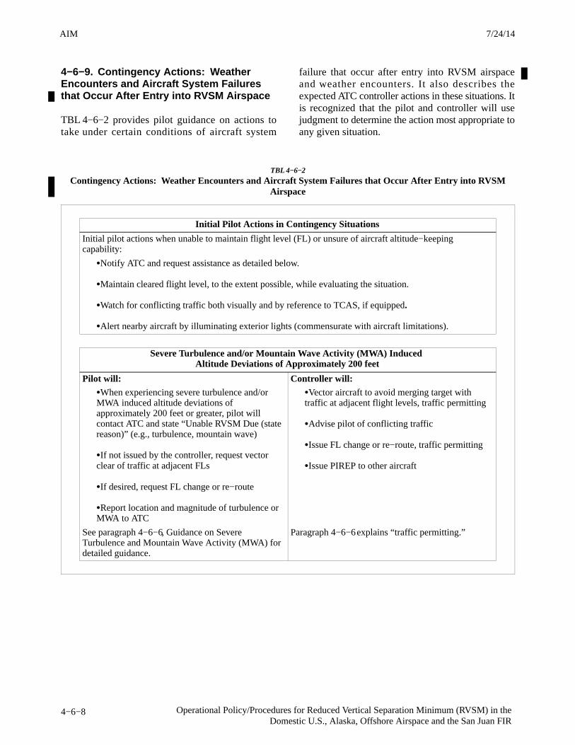
AIM 4/3/14
4−6−8 Operational Policy/Procedures for Reduced Vertical Separation Minimum (RVSM) in theDomestic U.S., Alaska, Offshore Airspace and the San Juan FIR
4−6−9. Contingency Actions: WeatherEncounters and Aircraft System Failuresthat Occur After Entry into RVSM Airspace
TBL 4−6−2 provides pilot guidance on actions totake under certain conditions of aircraft system
failure that occur after entry into RVSM airspaceand weather encounters. It also describes theexpected ATC controller actions in these situations. Itis recognized that the pilot and controller will usejudgment to determine the action most appropriate toany given situation.
TBL 4−6−2
Contingency Actions: Weather Encounters and Aircraft System Failures that Occur After Entry into RVSMAirspace
Initial Pilot Actions in Contingency Situations
Initial pilot actions when unable to maintain flight level (FL) or unsure of aircraft altitude−keepingcapability:
�Notify ATC and request assistance as detailed below.
�Maintain cleared flight level, to the extent possible, while evaluating the situation.
�Watch for conflicting traffic both visually and by reference to TCAS, if equipped.
�Alert nearby aircraft by illuminating exterior lights (commensurate with aircraft limitations).
Severe Turbulence and/or Mountain Wave Activity (MWA) Induced Altitude Deviations of Approximately 200 feet
Pilot will: Controller will:
�When experiencing severe turbulence and/orMWA induced altitude deviations ofapproximately 200 feet or greater, pilot willcontact ATC and state “Unable RVSM Due (statereason)” (e.g., turbulence, mountain wave)
�If not issued by the controller, request vectorclear of traffic at adjacent FLs
�If desired, request FL change or re−route
�Report location and magnitude of turbulence orMWA to ATC
�Vector aircraft to avoid merging target withtraffic at adjacent flight levels, traffic permitting
�Advise pilot of conflicting traffic
�Issue FL change or re−route, traffic permitting
�Issue PIREP to other aircraft
See paragraph 4−6−6, Guidance on SevereTurbulence and Mountain Wave Activity (MWA) fordetailed guidance.
Paragraph 4−6−6 explains “traffic permitting.”
3/15/077110.65R CHG 2AIM 7/24/14
AIM4/3/14
5−1−1Preflight
Chapter 5. Air Traffic Procedures
Section 1. Preflight
5−1−1. Preflight Preparation
a. Every pilot is urged to receive a preflightbriefing and to file a flight plan. This briefing shouldconsist of the latest or most current weather, airport,and en route NAVAID information. Briefing servicemay be obtained from an FSS either by telephone orinterphone, or by radio when airborne. Pilots with acurrent medical certificate in the 48 contiguous Statesmay access toll-free the Direct User Access TerminalSystem (DUATS) through a personal computer.DUATS will provide alpha-numeric preflight weath-er data and allow pilots to file domestic VFR or IFRflight plans.
REFERENCE−AIM, FAA Weather Services, Paragraph 7−1−2, lists DUATS vendors.
NOTE−Pilots filing flight plans via “fast file” who desire to havetheir briefing recorded, should include a statement at theend of the recording as to the source of their weatherbriefing.
b. The information required by the FAA to processflight plans is contained on FAA Form 7233−1, FlightPlan, or FAA Form 7233−4, International Flight Plan.The forms are available at all flight service stations.Additional copies will be provided on request.
REFERENCE−AIM, Flight Plan− VFR Flights, Paragraph 5−1−4AIM, Flight Plan− IFR Flights, Paragraph 5−1−8AIM, International Flight Plan− IFR Flights, Paragraph 5−1−9
c. Consult an FSS or a Weather Service Office(WSO) for preflight weather briefing. SupplementalWeather Service Locations (SWSLs) do not provideweather briefings.
d. FSSs are required to advise of pertinentNOTAMs if a standard briefing is requested, but ifthey are overlooked, don’t hesitate to remind thespecialist that you have not received NOTAMinformation.
NOTE−NOTAMs which are known in sufficient time forpublication and are of 7 days duration or longer arenormally incorporated into the Notices to AirmenPublication and carried there until cancellation time. FDCNOTAMs, which apply to instrument flight procedures, are
also included in the Notices to Airmen Publication up toand including the number indicated in the FDC NOTAMlegend. Printed NOTAMs are not provided during abriefing unless specifically requested by the pilot since theFSS specialist has no way of knowing whether the pilot hasalready checked the Notices to Airmen Publication prior tocalling. Remember to ask for NOTAMs in the Notices toAirmen Publication. This information is not normallyfurnished during your briefing.
REFERENCE−AIM, Notice to Airmen (NOTAM) System, Paragraph 5−1−3.
e. Pilots are urged to use only the latest issue ofaeronautical charts in planning and conducting flightoperations. Aeronautical charts are revised andreissued on a regular scheduled basis to ensure thatdepicted data are current and reliable. In theconterminous U.S., Sectional Charts are updatedevery 6 months, IFR En Route Charts every 56 days,and amendments to civil IFR Approach Charts areaccomplished on a 56−day cycle with a change noticevolume issued on the 28−day midcycle. Charts thathave been superseded by those of a more recent datemay contain obsolete or incomplete flightinformation.REFERENCE−AIM, General Description of Each Chart Series, Paragraph 9−1−4.
f. When requesting a preflight briefing, identifyyourself as a pilot and provide the following:
1. Type of flight planned; e.g., VFR or IFR.
2. Aircraft’s number or pilot’s name.
3. Aircraft type.
4. Departure Airport.
5. Route of flight.
6. Destination.
7. Flight altitude(s).
8. ETD and ETE.
g. Prior to conducting a briefing, briefers arerequired to have the background information listedabove so that they may tailor the briefing to the needsof the proposed flight. The objective is tocommunicate a “picture” of meteorological andaeronautical information necessary for the conduct of
7/24/14 AIM
AIM 4/3/14
5−1−2 Preflight
a safe and efficient flight. Briefers use all availableweather and aeronautical information to summarizedata applicable to the proposed flight. They do notread weather reports and forecasts verbatim unlessspecifically requested by the pilot. FSS briefers donot provide FDC NOTAM information for specialinstrument approach procedures unless specificallyasked. Pilots authorized by the FAA to use specialinstrument approach procedures must specificallyrequest FDC NOTAM information for theseprocedures. Pilots who receive the informationelectronically will receive NOTAMs for special IAPsautomatically.
REFERENCE−AIM, Preflight Briefings, Paragraph 7−1−4, contains those items of aweather briefing that should be expected or requested.
h. FAA by 14 CFR Part 93, Subpart K, hasdesignated High Density Traffic Airports (HDTAs)and has prescribed air traffic rules and requirementsfor operating aircraft (excluding helicopter opera-tions) to and from these airports.
REFERENCE−Airport/Facility Directory, Special Notices Section.AIM, Airport Reservation Operations and Special Traffic ManagementPrograms, Paragraph 4−1−22.
i. In addition to the filing of a flight plan, if theflight will traverse or land in one or more foreigncountries, it is particularly important that pilots leavea complete itinerary with someone directly concernedand keep that person advised of the flight’s progress.If serious doubt arises as to the safety of the flight, thatperson should first contact the FSS.
REFERENCE−AIM, Flights Outside the U.S. and U.S. Territories, Paragraph 5−1−11
j. Pilots operating under provisions of 14 CFRPart 135 on a domestic flight and not having an FAAassigned 3−letter designator, are urged to prefix thenormal registration (N) number with the letter “T” onflight plan filing; e.g., TN1234B.
REFERENCE−AIM, Aircraft Call Signs, Paragraph 4−2−4
5−1−2. Follow IFR Procedures Even WhenOperating VFR
a. To maintain IFR proficiency, pilots are urged topractice IFR procedures whenever possible, evenwhen operating VFR. Some suggested practicesinclude:
1. Obtain a complete preflight and weatherbriefing. Check the NOTAMs.
2. File a flight plan. This is an excellent low costinsurance policy. The cost is the time it takes to fill itout. The insurance includes the knowledge thatsomeone will be looking for you if you becomeoverdue at your destination.
3. Use current charts.
4. Use the navigation aids. Practice maintaininga good course−keep the needle centered.
5. Maintain a constant altitude which isappropriate for the direction of flight.
6. Estimate en route position times.
7. Make accurate and frequent position reportsto the FSSs along your route of flight.
b. Simulated IFR flight is recommended (underthe hood); however, pilots are cautioned to reviewand adhere to the requirements specified in 14 CFRSection 91.109 before and during such flight.
c. When flying VFR at night, in addition to thealtitude appropriate for the direction of flight, pilotsshould maintain an altitude which is at or above theminimum en route altitude as shown on charts. Thisis especially true in mountainous terrain, where thereis usually very little ground reference. Do not dependon your eyes alone to avoid rising unlighted terrain,or even lighted obstructions such as TV towers.
5−1−3. Notice to Airmen (NOTAM) System
a. Time-critical aeronautical information whichis of either a temporary nature or not sufficientlyknown in advance to permit publication onaeronautical charts or in other operational publica-tions receives immediate dissemination via theNational NOTAM System.NOTE−1. NOTAM information is that aeronautical informationthat could affect a pilot’s decision to make a flight. Itincludes such information as airport or aerodromeprimary runway closures, taxiways, ramps, obstructions,communications, airspace, changes in the status ofnavigational aids, ILSs, radar service availability, andother information essential to planned en route, terminal,or landing operations.
2. NOTAM information is transmitted using standardcontractions to reduce transmission time. See TBL 5−1−2for a listing of the most commonly used contractions. Fora complete listing, see FAA Order JO 7340.2,Contractions.
b. NOTAM information is classified into fivecategories. These are NOTAM (D) or distant, Flight
AIM4/3/14
5−3−3En Route Procedures
NOTE−The exchange of information between an aircraft and anARTCC through an FSS is quicker than relay via companyradio because the FSS has direct interphone lines to theresponsible ARTCC sector. Accordingly, when circum-stances dictate a choice between the two, during anARTCC frequency outage, relay via FSS radio isrecommended.
5−3−2. Position Reporting
The safety and effectiveness of traffic controldepends to a large extent on accurate positionreporting. In order to provide the proper separationand expedite aircraft movements, ATC must be ableto make accurate estimates of the progress of everyaircraft operating on an IFR flight plan.
a. Position Identification.
1. When a position report is to be made passinga VOR radio facility, the time reported should be thetime at which the first complete reversal of the“to/from” indicator is accomplished.
2. When a position report is made passing afacility by means of an airborne ADF, the timereported should be the time at which the indicatormakes a complete reversal.
3. When an aural or a light panel indication isused to determine the time passing a reporting point,such as a fan marker, Z marker, cone of silence orintersection of range courses, the time should benoted when the signal is first received and again whenit ceases. The mean of these two times should then betaken as the actual time over the fix.
4. If a position is given with respect to distanceand direction from a reporting point, the distance anddirection should be computed as accurately aspossible.
5. Except for terminal area transition purposes,position reports or navigation with reference to aidsnot established for use in the structure in which flightis being conducted will not normally be required byATC.
b. Position Reporting Points. CFRs requirepilots to maintain a listening watch on the appropriatefrequency and, unless operating under the provisionsof subparagraph c, to furnish position reports passingcertain reporting points. Reporting points areindicated by symbols on en route charts. The
designated compulsory reporting point symbol is a
solid triangle and the “on request” reporting
point symbol is the open triangle . Reportspassing an “on request” reporting point are onlynecessary when requested by ATC.
c. Position Reporting Requirements.
1. Flights Along Airways or Routes. Aposition report is required by all flights regardless ofaltitude, including those operating in accordance withan ATC clearance specifying “VFR−on−top,” overeach designated compulsory reporting point along theroute being flown.
2. Flights Along a Direct Route. Regardlessof the altitude or flight level being flown, includingflights operating in accordance with an ATCclearance specifying “VFR−on−top,” pilots mustreport over each reporting point used in the flight planto define the route of flight.
3. Flights in a Radar Environment. Wheninformed by ATC that their aircraft are in “RadarContact,” pilots should discontinue position reportsover designated reporting points. They shouldresume normal position reporting when ATC advises“RADAR CONTACT LOST” or “RADAR SERVICETERMINATED.”
4. Flights in an Oceanic (Non-radar) Envir-onment. Pilots must report over each point used inthe flight plan to define the route of flight, even if thepoint is depicted on aeronautical charts as an “onrequest” (non-compulsory) reporting point. Foraircraft providing automatic position reporting via anAutomatic Dependent Surveillance-Contract(ADS-C) logon, pilots should discontinue voiceposition reports.
NOTE−ATC will inform pilots that they are in “radar contact”:
(a) when their aircraft is initially identified in the ATCsystem; and
(b) when radar identification is reestablished afterradar service has been terminated or radar contact lost.Subsequent to being advised that the controller hasestablished radar contact, this fact will not be repeated tothe pilot when handed off to another controller. At times,the aircraft identity will be confirmed by the receivingcontroller; however, this should not be construed to meanthat radar contact has been lost. The identity oftransponder equipped aircraft will be confirmed by askingthe pilot to “ident,” “squawk standby,” or to change codes.Aircraft without transponders will be advised of theirposition to confirm identity. In this case, the pilot is
AIM 4/3/14
5−3−4 En Route Procedures
expected to advise the controller if in disagreement with theposition given. Any pilot who cannot confirm the accuracyof the position given because of not being tuned to theNAVAID referenced by the controller, should ask foranother radar position relative to the tuned in NAVAID.
d. Position Report Items:
1. Position reports should include the follow-ing items:
(a) Identification;
(b) Position;
(c) Time;
(d) Altitude or flight level (include actualaltitude or flight level when operating on a clearancespecifying VFR−on−top);
(e) Type of flight plan (not required in IFRposition reports made directly to ARTCCs orapproach control);
(f) ETA and name of next reporting point;
(g) The name only of the next succeedingreporting point along the route of flight; and
(h) Pertinent remarks.
5−3−3. Additional Reports
a. The following reports should be made toATC or FSS facilities without a specific ATCrequest:
1. At all times.
(a) When vacating any previously assignedaltitude or flight level for a newly assigned altitude orflight level.
(b) When an altitude change will be made ifoperating on a clearance specifying VFR−on−top.
(c) When unable to climb/descend at a rate ofa least 500 feet per minute.
(d) When approach has been missed.(Request clearance for specific action; i.e., toalternative airport, another approach, etc.)
(e) Change in the average true airspeed (atcruising altitude) when it varies by 5 percent or10 knots (whichever is greater) from that filed in theflight plan.
(f) The time and altitude or flight level uponreaching a holding fix or point to which cleared.
(g) When leaving any assigned holding fix orpoint.
NOTE−The reports in subparagraphs (f) and (g) may be omitted bypilots of aircraft involved in instrument training at militaryterminal area facilities when radar service is beingprovided.
(h) Any loss, in controlled airspace, of VOR,TACAN, ADF, low frequency navigation receivercapability, GPS anomalies while using installedIFR−certified GPS/GNSS receivers, complete orpartial loss of ILS receiver capability or impairmentof air/ground communications capability. Reportsshould include aircraft identification, equipmentaffected, degree to which the capability to operateunder IFR in the ATC system is impaired, and thenature and extent of assistance desired from ATC.
NOTE−1. Other equipment installed in an aircraft may effectivelyimpair safety and/or the ability to operate under IFR. Ifsuch equipment (e.g., airborne weather radar) malfunc-tions and in the pilot’s judgment either safety or IFRcapabilities are affected, reports should be made as above.
2. When reporting GPS anomalies, include the locationand altitude of the anomaly. Be specific when describingthe location and include duration of the anomaly ifnecessary.
(i) Any information relating to the safety offlight.
2. When not in radar contact.
(a) When leaving final approach fix inboundon final approach (nonprecision approach) or whenleaving the outer marker or fix used in lieu of the outermarker inbound on final approach (precisionapproach).
(b) A corrected estimate at anytime itbecomes apparent that an estimate as previouslysubmitted is in error in excess of 2 minutes. Forflights in the North Atlantic (NAT), a revisedestimate is required if the error is 3 minutes or more.
b. Pilots encountering weather conditions whichhave not been forecast, or hazardous conditionswhich have been forecast, are expected to forward areport of such weather to ATC.
REFERENCE−AIM, Pilot Weather Reports (PIREPs), Paragraph 7−1−20.14 CFR Section 91.183(B) and (C).
3/15/077110.65R CHG 2AIM 7/24/14

AIM4/3/14
5−4−3Arrival Procedures
flight crew of a loss of GPS, the operator mustdevelop procedures to verify correct GPS operation.
REFERENCE−AIM, Global Positioning System (GPS)Paragraph 1−1−18l, Impact of Magnetic Variation on RNAV Sys-tems
5−4−2. Local Flow Traffic Management Pro-gram
a. This program is a continuing effort by the FAAto enhance safety, minimize the impact of aircraftnoise and conserve aviation fuel. The enhancement ofsafety and reduction of noise is achieved in thisprogram by minimizing low altitude maneuvering ofarriving turbojet and turboprop aircraft weighingmore than 12,500 pounds and, by permittingdeparture aircraft to climb to higher altitudes sooner,as arrivals are operating at higher altitudes at thepoints where their flight paths cross. The applicationof these procedures also reduces exposure timebetween controlled aircraft and uncontrolled aircraftat the lower altitudes in and around the terminalenvironment. Fuel conservation is accomplished byabsorbing any necessary arrival delays for aircraftincluded in this program operating at the higher andmore fuel efficient altitudes.
b. A fuel efficient descent is basically anuninterrupted descent (except where level flight isrequired for speed adjustment) from cruising altitudeto the point when level flight is necessary for the pilotto stabilize the aircraft on final approach. Theprocedure for a fuel efficient descent is based on analtitude loss which is most efficient for the majorityof aircraft being served. This will generally result ina descent gradient window of 250−350 feet pernautical mile.
c. When crossing altitudes and speed restrictionsare issued verbally or are depicted on a chart, ATCwill expect the pilot to descend first to the crossingaltitude and then reduce speed. Verbal clearances fordescent will normally permit an uninterrupteddescent in accordance with the procedure asdescribed in paragraph b above. Acceptance of acharted fuel efficient descent (Runway ProfileDescent) clearance requires the pilot to adhere to thealtitudes, speeds, and headings depicted on the chartsunless otherwise instructed by ATC. PILOTSRECEIVING A CLEARANCE FOR A FUELEFFICIENT DESCENT ARE EXPECTED TO
ADVISE ATC IF THEY DO NOT HAVE RUNWAYPROFILE DESCENT CHARTS PUBLISHED FORTHAT AIRPORT OR ARE UNABLE TO COMPLYWITH THE CLEARANCE.
5−4−3. Approach Control
a. Approach control is responsible for controllingall instrument flight operating within its area ofresponsibility. Approach control may serve one ormore airfields, and control is exercised primarily bydirect pilot and controller communications. Prior toarriving at the destination radio facility, instructionswill be received from ARTCC to contact approachcontrol on a specified frequency.
b. Radar Approach Control.
1. Where radar is approved for approach controlservice, it is used not only for radar approaches(Airport Surveillance Radar [ASR] and PrecisionApproach Radar [PAR]) but is also used to providevectors in conjunction with published nonradarapproaches based on radio NAVAIDs (ILS, VOR,NDB, TACAN). Radar vectors can provide courseguidance and expedite traffic to the final approachcourse of any established IAP or to the traffic patternfor a visual approach. Approach control facilities thatprovide this radar service will operate in the follow-ing manner:
(a) Arriving aircraft are either cleared to anouter fix most appropriate to the route being flownwith vertical separation and, if required, givenholding information or, when radar handoffs areeffected between the ARTCC and approach control,or between two approach control facilities, aircraftare cleared to the airport or to a fix so located that thehandoff will be completed prior to the time theaircraft reaches the fix. When radar handoffs areutilized, successive arriving flights may be handedoff to approach control with radar separation in lieuof vertical separation.
(b) After release to approach control, aircraftare vectored to the final approach course (ILS, RNAV,GLS, VOR, ADF, etc.). Radar vectors and altitude orflight levels will be issued as required for spacing andseparating aircraft. Therefore, pilots must not deviatefrom the headings issued by approach control.Aircraft will normally be informed when it isnecessary to vector across the final approach coursefor spacing or other reasons. If approach coursecrossing is imminent and the pilot has not been
7/24/14 AIM
AIM 4/3/14
5−4−4 Arrival Procedures
informed that the aircraft will be vectored across thefinal approach course, the pilot should query thecontroller.
(c) The pilot is not expected to turn inboundon the final approach course unless an approachclearance has been issued. This clearance willnormally be issued with the final vector forinterception of the final approach course, and thevector will be such as to enable the pilot to establishthe aircraft on the final approach course prior toreaching the final approach fix.
(d) In the case of aircraft already inbound onthe final approach course, approach clearance will beissued prior to the aircraft reaching the final approachfix. When established inbound on the final approachcourse, radar separation will be maintained and thepilot will be expected to complete the approachutilizing the approach aid designated in the clearance(ILS, RNAV, GLS, VOR, radio beacons, etc.) as theprimary means of navigation. Therefore, once estab-lished on the final approach course, pilots must notdeviate from it unless a clearance to do so is receivedfrom ATC.
(e) After passing the final approach fix onfinal approach, aircraft are expected to continueinbound on the final approach course and completethe approach or effect the missed approach procedurepublished for that airport.
2. ARTCCs are approved for and may provideapproach control services to specific airports. Theradar systems used by these centers do not provide thesame precision as an ASR/PAR used by approachcontrol facilities and towers, and the update rate is notas fast. Therefore, pilots may be requested to reportestablished on the final approach course.
3. Whether aircraft are vectored to the appropri-ate final approach course or provide their ownnavigation on published routes to it, radar service isautomatically terminated when the landing iscompleted or when instructed to change to advisoryfrequency at uncontrolled airports, whichever occursfirst.
5−4−4. Advance Information on InstrumentApproach
a. When landing at airports with approach controlservices and where two or more IAPs are published,pilots will be provided in advance of their arrival with
the type of approach to expect or that they may bevectored for a visual approach. This information willbe broadcast either by a controller or on ATIS. It willnot be furnished when the visibility is three miles orbetter and the ceiling is at or above the highest initialapproach altitude established for any low altitude IAPfor the airport.
b. The purpose of this information is to aid thepilot in planning arrival actions; however, it is not anATC clearance or commitment and is subject tochange. Pilots should bear in mind that fluctuatingweather, shifting winds, blocked runway, etc., areconditions which may result in changes to approachinformation previously received. It is important thatpilots advise ATC immediately they are unable toexecute the approach ATC advised will be used, or ifthey prefer another type of approach.
c. Aircraft destined to uncontrolled airports,which have automated weather data with broadcastcapability, should monitor the ASOS/AWSS/AWOSfrequency to ascertain the current weather for the air-port. The pilot must advise ATC when he/she hasreceived the broadcast weather and state his/herintentions.
NOTE−1. ASOS/AWSS/AWOS should be set to provide one−minute broadcast weather updates at uncontrolled airportsthat are without weather broadcast capability by a humanobserver.
2. Controllers will consider the long line disseminatedweather from an automated weather system at anuncontrolled airport as trend and planning informationonly and will rely on the pilot for current weatherinformation for the airport. If the pilot is unable to receivethe current broadcast weather, the last long linedisseminated weather will be issued to the pilot. Whenreceiving IFR services, the pilot/aircraft operator isresponsible for determining if weather/visibility isadequate for approach/landing.
d. When making an IFR approach to an airport notserved by a tower or FSS, after ATC advises“CHANGE TO ADVISORY FREQUENCY AP-PROVED” you should broadcast your intentions,including the type of approach being executed, yourposition, and when over the final approach fixinbound (nonprecision approach) or when over theouter marker or fix used in lieu of the outer markerinbound (precision approach). Continue to monitorthe appropriate frequency (UNICOM, etc.) forreports from other pilots.
3/15/077110.65R CHG 2AIM 7/24/14
AIM4/3/14
5−4−7Arrival Procedures
course and glidepath deviation information meetingthe precision standards of ICAO Annex 10. Forexample, PAR, ILS, and GLS are precisionapproaches.
(b) Approach with Vertical Guidance (APV).An instrument approach based on a navigationsystem that is not required to meet the precisionapproach standards of ICAO Annex 10 but providescourse and glidepath deviation information. Forexample, Baro−VNAV, LDA with glidepath,LNAV/VNAV and LPV are APV approaches.
(c) Nonprecision Approach (NPA). An in-strument approach based on a navigation systemwhich provides course deviation information, but noglidepath deviation information. For example, VOR,NDB and LNAV. As noted in subparagraph k, VerticalDescent Angle (VDA) on Nonprecision Approaches,some approach procedures may provide a VerticalDescent Angle as an aid in flying a stabilizedapproach, without requiring its use in order to fly theprocedure. This does not make the approach an APVprocedure, since it must still be flown to an MDA andhas not been evaluated with a glidepath.
b. The method used to depict prescribed altitudeson instrument approach charts differs according totechniques employed by different chart publishers.Prescribed altitudes may be depicted in four differentconfigurations: minimum, maximum, mandatory,and recommended. The U.S. Government distributescharts produced by National Geospatial−IntelligenceAgency (NGA) and FAA. Altitudes are depicted onthese charts in the profile view with underscore,overscore, both or none to identify them as minimum,maximum, mandatory or recommended.
1. Minimum altitude will be depicted with thealtitude value underscored. Aircraft are required tomaintain altitude at or above the depicted value,e.g., 3000.
2. Maximum altitude will be depicted with thealtitude value overscored. Aircraft are required tomaintain altitude at or below the depicted value,e.g., 4000.
3. Mandatory altitude will be depicted with thealtitude value both underscored and overscored.Aircraft are required to maintain altitude at thedepicted value, e.g., 5000.
4. Recommended altitude will be depicted withno overscore or underscore. These altitudes aredepicted for descent planning, e.g., 6000.
NOTE−1. Pilots are cautioned to adhere to altitudes as prescribedbecause, in certain instances, they may be used as the basisfor vertical separation of aircraft by ATC. When a depictedaltitude is specified in the ATC clearance, that altitude be-comes mandatory as defined above.
2. The ILS glide slope is intended to be intercepted at thepublished glide slope intercept altitude. This point marksthe PFAF and is depicted by the ”lightning bolt” symbolon U.S. Government charts. Intercepting the glide slopeat this altitude marks the beginning of the finalapproach segment and ensures required obstacleclearance during descent from the glide slope interceptaltitude to the lowest published decision altitude forthe approach. Interception and tracking of the glide slopeprior to the published glide slope interception altitudedoes not necessarily ensure that minimum, maximum,and/or mandatory altitudes published for any precedingfixes will be complied with during the descent. If the pilotchooses to track the glide slope prior to the glide slopeinterception altitude, they remain responsible forcomplying with published altitudes for any precedingstepdown fixes encountered during the subsequentdescent.
3. Approaches used for simultaneous (parallel)independent and simultaneous close parallel operationsprocedurally require descending on the glideslope from thealtitude at which the approach clearance is issued (refer to5-4-15 and 5-4-16). For simultaneous close parallel(PRM) approaches, the Attention All Users Page (AAUP)may publish a note which indicates that descending on theglideslope/glidepath meets all crossing restrictions.However, if no such note is published, and for simultaneousindependent approaches (4300 and greater runwayseparation) where an AAUP is not published, pilots arecautioned to monitor their descent on the glideslope/pathoutside of the PFAF to ensure compliance with publishedcrossing restrictions during simultaneous operations.
4. When parallel approach courses are less than 2500 feetapart and reduced in-trail spacing is authorized forsimultaneous dependent operations, a chart note willindicate that simultaneous operations require use ofvertical guidance and that the pilot should maintain lastassigned altitude until established on glide slope. Theseapproaches procedurally require utilization of the ILSglide slope for wake turbulence mitigation. Pilots shouldnot confuse these simultaneous dependent operations with(SOIA) simultaneous close parallel PRM approaches,where PRM appears in the approach title.
7/24/14 AIM
AIM 4/3/14
5−4−8 Arrival Procedures
c. Minimum Safe/Sector Altitudes (MSA) arepublished for emergency use on IAP charts. Forconventional navigation systems, the MSA isnormally based on the primary omnidirectionalfacility on which the IAP is predicated. The MSAdepiction on the approach chart contains the facilityidentifier of the NAVAID used to determine the MSAaltitudes. For RNAV approaches, the MSA is basedon the runway waypoint (RWY WP) for straight−inapproaches, or the airport waypoint (APT WP) forcircling approaches. For GPS approaches, the MSAcenter will be the missed approach waypoint(MAWP). MSAs are expressed in feet above meansea level and normally have a 25 NM radius;however, this radius may be expanded to 30 NM ifnecessary to encompass the airport landing surfaces.Ideally, a single sector altitude is established anddepicted on the plan view of approach charts;however, when necessary to obtain relief fromobstructions, the area may be further sectored and asmany as four MSAs established. When established,sectors may be no less than 90� in spread. MSAsprovide 1,000 feet clearance over all obstructions butdo not necessarily assure acceptable navigationsignal coverage.
d. Terminal Arrival Area (TAA)
1. The TAA provides a transition from the enroute structure to the terminal environment with littlerequired pilot/air traffic control interface for aircraft
equipped with Area Navigation (RNAV) systems. ATAA provides minimum altitudes with standardobstacle clearance when operating within the TAAboundaries. TAAs are primarily used on RNAVapproaches but may be used on an ILS approach whenRNAV is the sole means for navigation to the IF;however, they are not normally used in areas of heavyconcentration of air traffic.
2. The basic design of the RNAV procedureunderlying the TAA is normally the “T” design (alsocalled the “Basic T”). The “T” design incorporatestwo IAFs plus a dual purpose IF/IAF that functions asboth an intermediate fix and an initial approach fix.The T configuration continues from the IF/IAF to thefinal approach fix (FAF) and then to the missedapproach point (MAP). The two base leg IAFs aretypically aligned in a straight-line perpendicular tothe intermediate course connecting at the IF/IAF. AHold-in-Lieu-of Procedure Turn (HILPT) isanchored at the IF/IAF and depicted on U.S.Government publications using the “hold−in−lieu−of−PT” holding pattern symbol. When the HILPT isnecessary for course alignment and/or descent, thedual purpose IF/IAF serves as an IAF during the entryinto the pattern. Following entry into the HILPTpattern and when flying a route or sector labeled“NoPT,” the dual-purpose fix serves as an IF, markingthe beginning of the Intermediate Segment. SeeFIG 5−4−1 and FIG 5−4−2 for the Basic “T” TAAconfiguration.
3/15/077110.65R CHG 2AIM 7/24/14
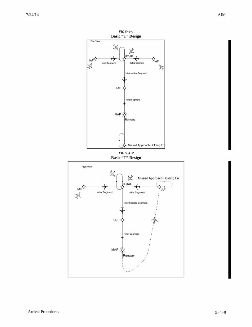
AIM4/3/14
5−4−9Arrival Procedures
FIG 5−4−1
Basic “T” Design
FIG 5−4−2
Basic “T” Design
7/24/14 AIM
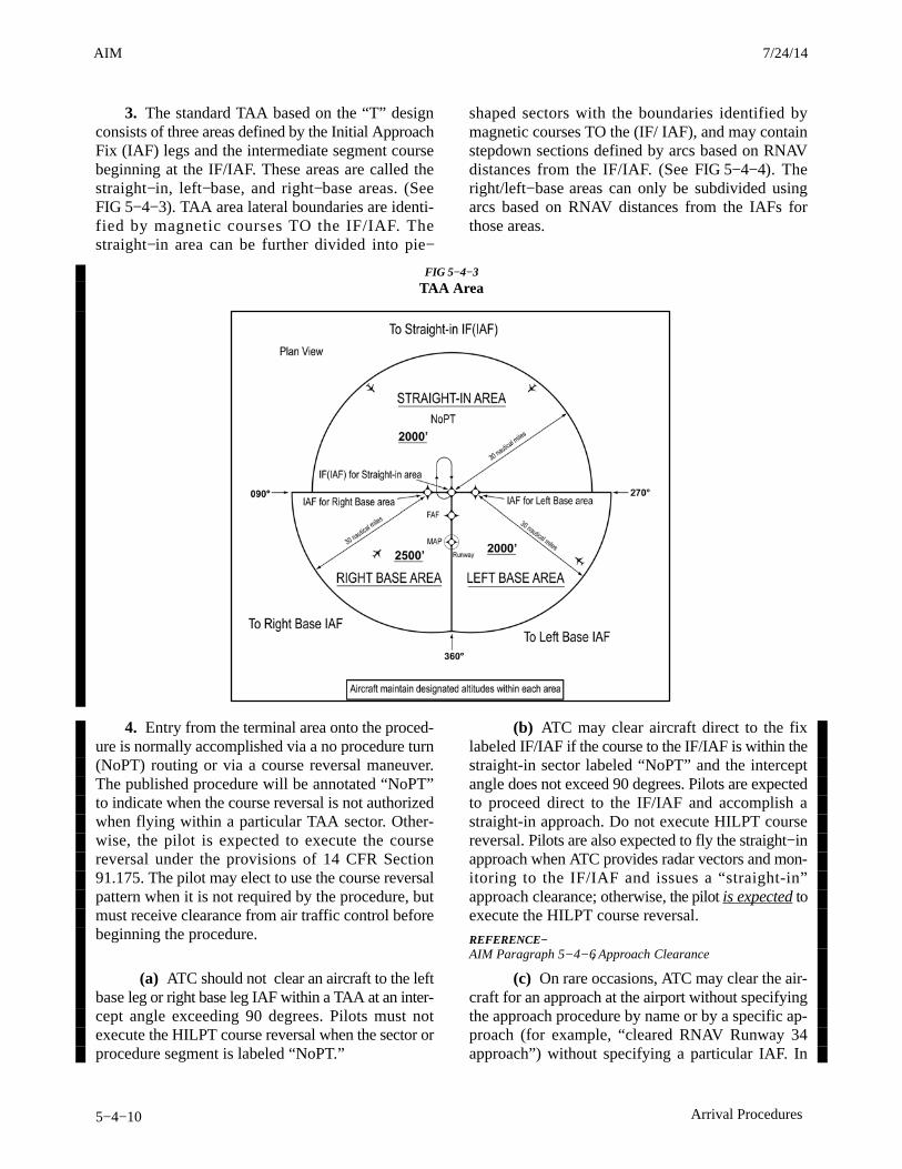
AIM 4/3/14
5−4−10 Arrival Procedures
3. The standard TAA based on the “T” designconsists of three areas defined by the Initial ApproachFix (IAF) legs and the intermediate segment coursebeginning at the IF/IAF. These areas are called thestraight−in, left−base, and right−base areas. (SeeFIG 5−4−3). TAA area lateral boundaries are identi-fied by magnetic courses TO the IF/IAF. Thestraight−in area can be further divided into pie−
shaped sectors with the boundaries identified bymagnetic courses TO the (IF/ IAF), and may containstepdown sections defined by arcs based on RNAVdistances from the IF/IAF. (See FIG 5−4−4). Theright/left−base areas can only be subdivided usingarcs based on RNAV distances from the IAFs forthose areas.
FIG 5−4−3
TAA Area
4. Entry from the terminal area onto the proced-ure is normally accomplished via a no procedure turn(NoPT) routing or via a course reversal maneuver.The published procedure will be annotated “NoPT”to indicate when the course reversal is not authorizedwhen flying within a particular TAA sector. Other-wise, the pilot is expected to execute the coursereversal under the provisions of 14 CFR Section91.175. The pilot may elect to use the course reversalpattern when it is not required by the procedure, butmust receive clearance from air traffic control beforebeginning the procedure.
(a) ATC should not clear an aircraft to the leftbase leg or right base leg IAF within a TAA at an inter-cept angle exceeding 90 degrees. Pilots must notexecute the HILPT course reversal when the sector orprocedure segment is labeled “NoPT.”
(b) ATC may clear aircraft direct to the fixlabeled IF/IAF if the course to the IF/IAF is within thestraight-in sector labeled “NoPT” and the interceptangle does not exceed 90 degrees. Pilots are expectedto proceed direct to the IF/IAF and accomplish astraight-in approach. Do not execute HILPT coursereversal. Pilots are also expected to fly the straight−inapproach when ATC provides radar vectors and mon-itoring to the IF/IAF and issues a “straight-in”approach clearance; otherwise, the pilot is expected toexecute the HILPT course reversal.
REFERENCE−AIM Paragraph 5−4−6, Approach Clearance
(c) On rare occasions, ATC may clear the air-craft for an approach at the airport without specifyingthe approach procedure by name or by a specific ap-proach (for example, “cleared RNAV Runway 34approach”) without specifying a particular IAF. In
3/15/077110.65R CHG 2AIM 7/24/14

AIM4/3/14
5−4−11Arrival Procedures
either case, the pilot should proceed direct to the IAFor to the IF/IAF associated with the sector that theaircraft will enter the TAA and join the approachcourse from that point and if required by that sector(i.e., sector is not labeled “NoPT), complete theHILPT course reversal.
NOTE−If approaching with a TO bearing that is on a sector bound-ary, the pilot is expected to proceed in accordance with a“NoPT” routing unless otherwise instructed by ATC.
5. Altitudes published within the TAA replacethe MSA altitude. However, unlike MSA altitudes theTAA altitudes are operationally usable altitudes.These altitudes provide at least 1,000 feet of obstacleclearance, more in mountainous areas. It is importantthat the pilot knows which area of the TAA the aircraftwill enter in order to comply with the minimum alti-tude requirements. The pilot can determine whicharea of the TAA the aircraft will enter by determiningthe magnetic bearing of the aircraft TO the fix labeledIF/IAF. The bearing should then be compared to thepublished lateral boundary bearings that define theTAA areas. Do not use magnetic bearing to theright-base or left-base IAFs to determine position.
(a) An ATC clearance direct to an IAF or tothe IF/IAF without an approach clearance does not
authorize a pilot to descend to a lower TAA altitude.If a pilot desires a lower altitude without an approachclearance, request the lower TAA altitude from ATC.Pilots not sure of the clearance should confirm theirclearance with ATC or request a specific clearance.Pilots entering the TAA with two−way radio commu-nications failure (14 CFR Section 91.185, IFROperations: Two−way Radio Communications Fail-ure), must maintain the highest altitude prescribed bySection 91.185(c)(2) until arriving at the appropriateIAF.
(b) Once cleared for the approach, pilots maydescend in the TAA sector to the minimum altitudedepicted within the defined area/subdivision, unlessinstructed otherwise by air traffic control. Pilotsshould plan their descent within the TAA to permit anormal descent from the IF/IAF to the FAF. InFIG 5−4−4, pilots within the left or right−base areasare expected to maintain a minimum altitude of 6,000feet until within 17 NM of the associated IAF. Aftercrossing the 17 NM arc, descent is authorized to thelower charted altitudes. Pilots approaching from thenorthwest are expected to maintain a minimum alti-tude of 6,000 feet, and when within 22 NM of theIF/IAF, descend to a minimum altitude of 2,000 feetMSL until crossing the IF/IAF.
FIG 5−4−4
Sectored TAA Areas
7/24/14 AIM
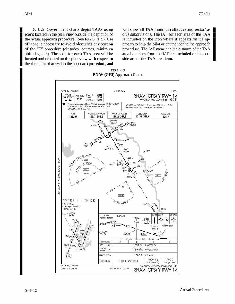
AIM 4/3/14
5−4−12 Arrival Procedures
6. U.S. Government charts depict TAAs usingicons located in the plan view outside the depiction ofthe actual approach procedure. (See FIG 5−4−5). Useof icons is necessary to avoid obscuring any portionof the “T” procedure (altitudes, courses, minimumaltitudes, etc.). The icon for each TAA area will belocated and oriented on the plan view with respect tothe direction of arrival to the approach procedure, and
will show all TAA minimum altitudes and sector/ra-dius subdivisions. The IAF for each area of the TAAis included on the icon where it appears on the ap-proach to help the pilot orient the icon to the approachprocedure. The IAF name and the distance of the TAAarea boundary from the IAF are included on the out-side arc of the TAA area icon.
FIG 5−4−5
RNAV (GPS) Approach Chart
3/15/077110.65R CHG 2AIM 7/24/14
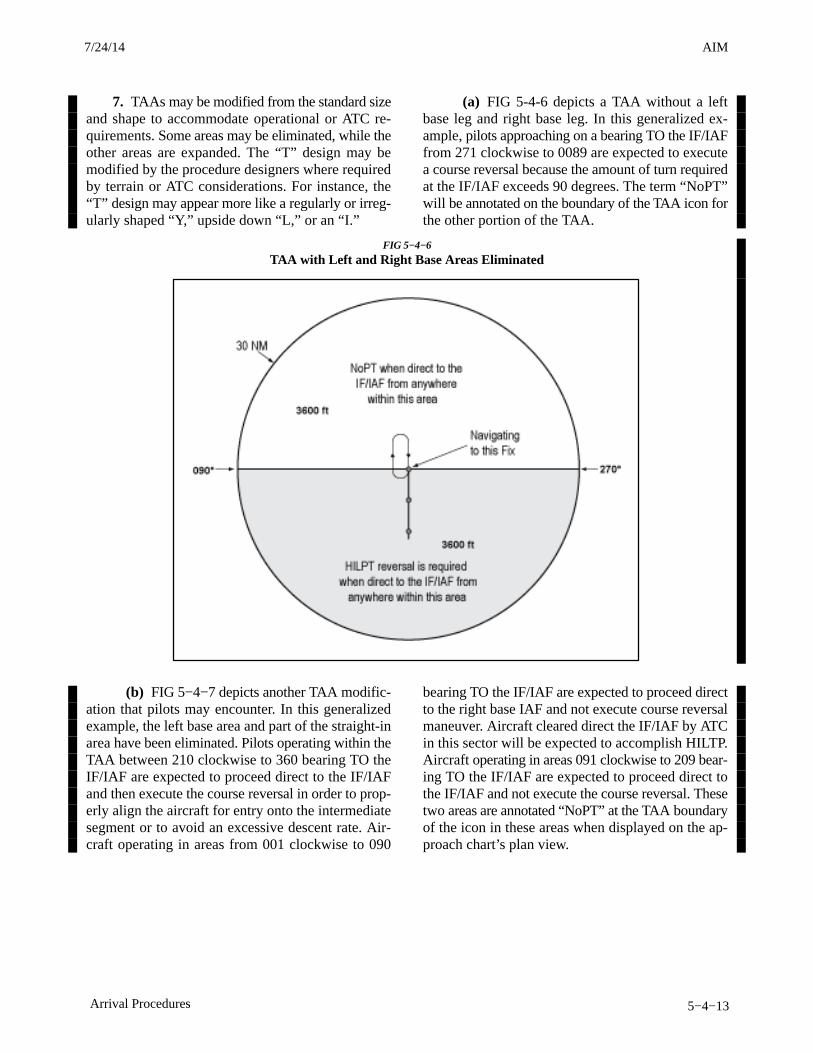
AIM4/3/14
5−4−13Arrival Procedures
7. TAAs may be modified from the standard sizeand shape to accommodate operational or ATC re-quirements. Some areas may be eliminated, while theother areas are expanded. The “T” design may bemodified by the procedure designers where requiredby terrain or ATC considerations. For instance, the“T” design may appear more like a regularly or irreg-ularly shaped “Y,” upside down “L,” or an “I.”
(a) FIG 5-4-6 depicts a TAA without a leftbase leg and right base leg. In this generalized ex-ample, pilots approaching on a bearing TO the IF/IAFfrom 271 clockwise to 0089 are expected to executea course reversal because the amount of turn requiredat the IF/IAF exceeds 90 degrees. The term “NoPT”will be annotated on the boundary of the TAA icon forthe other portion of the TAA.
FIG 5−4−6
TAA with Left and Right Base Areas Eliminated
(b) FIG 5−4−7 depicts another TAA modific-ation that pilots may encounter. In this generalizedexample, the left base area and part of the straight-inarea have been eliminated. Pilots operating within theTAA between 210 clockwise to 360 bearing TO theIF/IAF are expected to proceed direct to the IF/IAFand then execute the course reversal in order to prop-erly align the aircraft for entry onto the intermediatesegment or to avoid an excessive descent rate. Air-craft operating in areas from 001 clockwise to 090
bearing TO the IF/IAF are expected to proceed directto the right base IAF and not execute course reversalmaneuver. Aircraft cleared direct the IF/IAF by ATCin this sector will be expected to accomplish HILTP.Aircraft operating in areas 091 clockwise to 209 bear-ing TO the IF/IAF are expected to proceed direct tothe IF/IAF and not execute the course reversal. Thesetwo areas are annotated “NoPT” at the TAA boundaryof the icon in these areas when displayed on the ap-proach chart’s plan view.
7/24/14 AIM
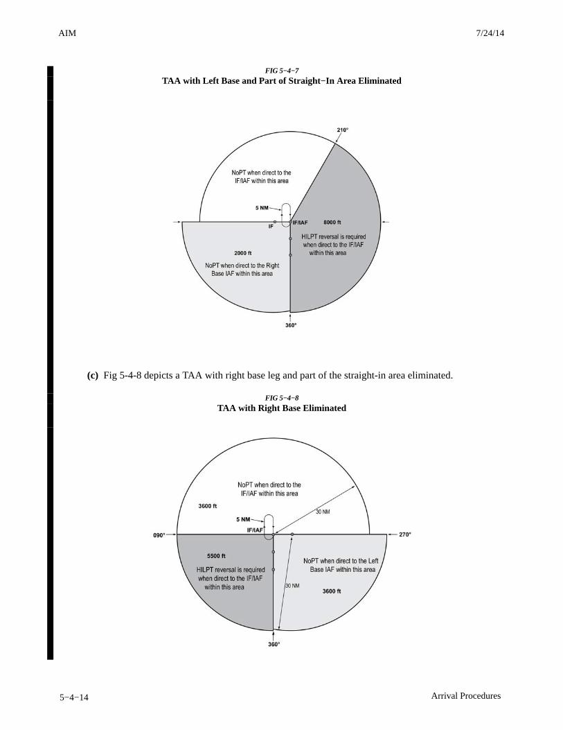
AIM 4/3/14
5−4−14 Arrival Procedures
FIG 5−4−7
TAA with Left Base and Part of Straight−In Area Eliminated
(c) Fig 5-4-8 depicts a TAA with right base leg and part of the straight-in area eliminated.
FIG 5−4−8
TAA with Right Base Eliminated
3/15/077110.65R CHG 2AIM 7/24/14

AIM4/3/14
5−4−15Arrival Procedures
8. When an airway does not cross the lateralTAA boundaries, a feeder route will be establishedfrom an airway fix or NAVAID to the TAA boundaryto provide a transition from the en route structure tothe appropriate IAF. Each feeder route will terminate
at the TAA boundary and will be aligned along a pathpointing to the associated IAF. Pilots should descendto the TAA altitude after crossing the TAA boundaryand cleared for the approach by ATC. (See FIG 5−4−9).
FIG 5−4−9
Examples of a TAA with Feeders from an Airway
9. Each waypoint on the “T” is assigned apronounceable 5−letter name, except the missedapproach waypoint. These names are used for ATCcommunications, RNAV databases, and aeronautical
navigation products. The missed approach waypointis assigned a pronounceable name when it is notlocated at the runway threshold.
7/24/14 AIM
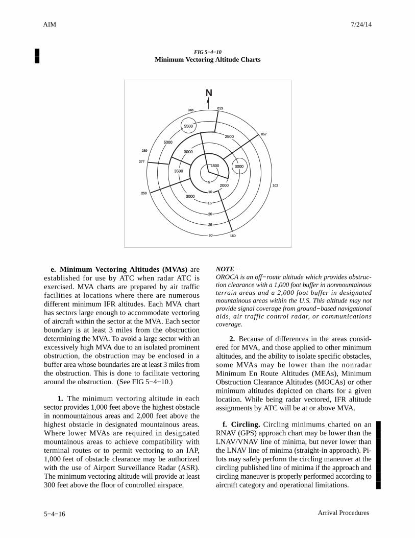
AIM 4/3/14
5−4−16 Arrival Procedures
FIG 5−4−10
Minimum Vectoring Altitude Charts
1500
2000
3000
3000
3000
3500
25005000
5500
5
10
15
20
25
30
348 013
057
102
160
250
277
289
N
e. Minimum Vectoring Altitudes (MVAs) areestablished for use by ATC when radar ATC isexercised. MVA charts are prepared by air trafficfacilities at locations where there are numerousdifferent minimum IFR altitudes. Each MVA charthas sectors large enough to accommodate vectoringof aircraft within the sector at the MVA. Each sectorboundary is at least 3 miles from the obstructiondetermining the MVA. To avoid a large sector with anexcessively high MVA due to an isolated prominentobstruction, the obstruction may be enclosed in abuffer area whose boundaries are at least 3 miles fromthe obstruction. This is done to facilitate vectoringaround the obstruction. (See FIG 5−4−10.)
1. The minimum vectoring altitude in eachsector provides 1,000 feet above the highest obstaclein nonmountainous areas and 2,000 feet above thehighest obstacle in designated mountainous areas.Where lower MVAs are required in designatedmountainous areas to achieve compatibility withterminal routes or to permit vectoring to an IAP,1,000 feet of obstacle clearance may be authorizedwith the use of Airport Surveillance Radar (ASR).The minimum vectoring altitude will provide at least300 feet above the floor of controlled airspace.
NOTE−OROCA is an off−route altitude which provides obstruc-tion clearance with a 1,000 foot buffer in nonmountainousterrain areas and a 2,000 foot buffer in designatedmountainous areas within the U.S. This altitude may notprovide signal coverage from ground−based navigationalaids, air traffic control radar, or communicationscoverage.
2. Because of differences in the areas consid-ered for MVA, and those applied to other minimumaltitudes, and the ability to isolate specific obstacles,some MVAs may be lower than the nonradarMinimum En Route Altitudes (MEAs), MinimumObstruction Clearance Altitudes (MOCAs) or otherminimum altitudes depicted on charts for a givenlocation. While being radar vectored, IFR altitudeassignments by ATC will be at or above MVA.
f. Circling. Circling minimums charted on anRNAV (GPS) approach chart may be lower than theLNAV/VNAV line of minima, but never lower thanthe LNAV line of minima (straight-in approach). Pi-lots may safely perform the circling maneuver at thecircling published line of minima if the approach andcircling maneuver is properly performed according toaircraft category and operational limitations.
3/15/077110.65R CHG 2AIM 7/24/14
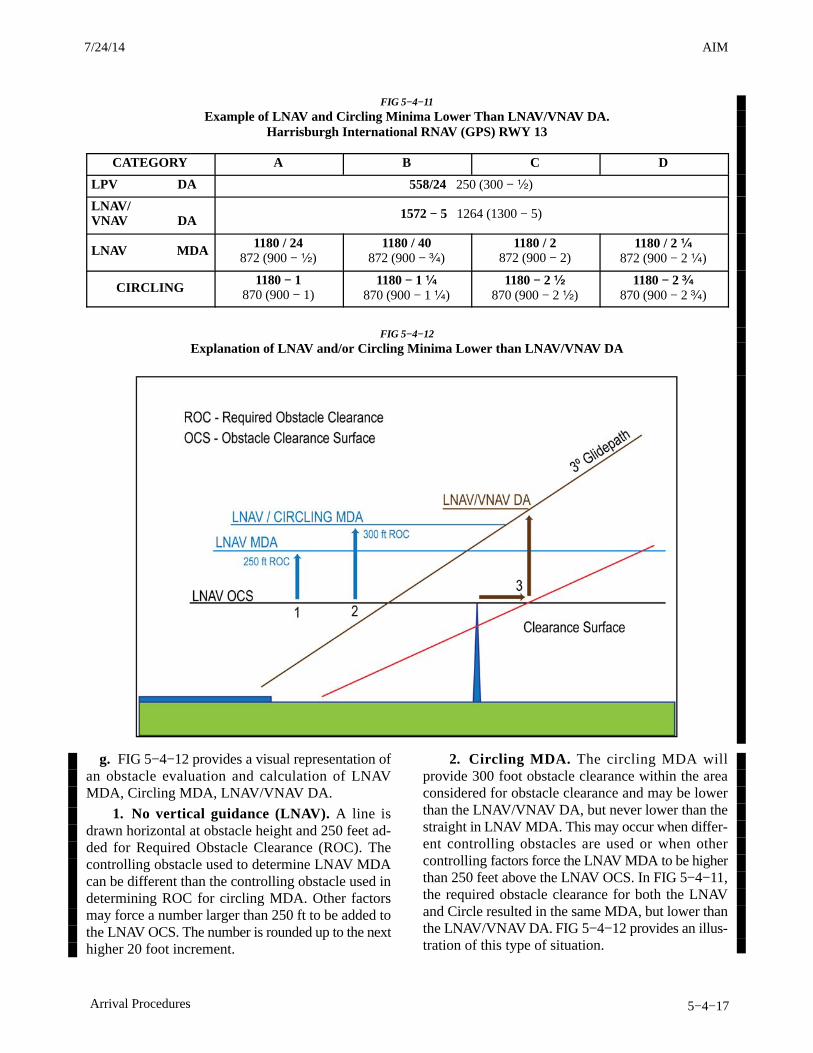
AIM4/3/14
5−4−17Arrival Procedures
FIG 5−4−11
Example of LNAV and Circling Minima Lower Than LNAV/VNAV DA.Harrisburgh International RNAV (GPS) RWY 13
CATEGORY A B C D
LPV DA 558/24 250 (300 − ½)
LNAV/VNAV DA 1572 − 5 1264 (1300 − 5)
LNAV MDA 1180 / 24872 (900 − ½)
1180 / 40872 (900 − ¾)
1180 / 2872 (900 − 2)
1180 / 2 ¼872 (900 − 2 ¼)
CIRCLING 1180 − 1870 (900 − 1)
1180 − 1 ¼870 (900 − 1 ¼)
1180 − 2 ½870 (900 − 2 ½)
1180 − 2 ¾870 (900 − 2 ¾)
FIG 5−4−12
Explanation of LNAV and/or Circling Minima Lower than LNAV/VNAV DA
g. FIG 5−4−12 provides a visual representation ofan obstacle evaluation and calculation of LNAVMDA, Circling MDA, LNAV/VNAV DA.
1. No vertical guidance (LNAV). A line isdrawn horizontal at obstacle height and 250 feet ad-ded for Required Obstacle Clearance (ROC). Thecontrolling obstacle used to determine LNAV MDAcan be different than the controlling obstacle used indetermining ROC for circling MDA. Other factorsmay force a number larger than 250 ft to be added tothe LNAV OCS. The number is rounded up to the nexthigher 20 foot increment.
2. Circling MDA. The circling MDA willprovide 300 foot obstacle clearance within the areaconsidered for obstacle clearance and may be lowerthan the LNAV/VNAV DA, but never lower than thestraight in LNAV MDA. This may occur when differ-ent controlling obstacles are used or when othercontrolling factors force the LNAV MDA to be higherthan 250 feet above the LNAV OCS. In FIG 5−4−11,the required obstacle clearance for both the LNAVand Circle resulted in the same MDA, but lower thanthe LNAV/VNAV DA. FIG 5−4−12 provides an illus-tration of this type of situation.
7/24/14 AIM
AIM 4/3/14
5−4−18 Arrival Procedures
3. Vertical guidance (LNAV/VNAV). A line isdrawn horizontal at obstacle height until reaching theobstacle clearance surface (OCS). At the OCS, a ver-tical line is drawn until reaching the glide path. Thisis the DA for the approach. This method places the of-fending obstacle in front of the LNAV/VNAV DA soit can be seen and avoided. In some situations, thismay result in the LNAV/VNAV DA being higher thanthe LNAV and/or Circling MDA.
h. Visual Descent Points (VDPs) are beingincorporated in nonprecision approach procedures.The VDP is a defined point on the final approachcourse of a nonprecision straight−in approachprocedure from which normal descent from the MDAto the runway touchdown point may be commenced,provided visual reference required by 14 CFRSection 91.175(c)(3) is established. The VDP willnormally be identified by DME on VOR and LOCprocedures and by along−track distance to the nextwaypoint for RNAV procedures. The VDP isidentified on the profile view of the approach chart bythe symbol: V.
1. VDPs are intended to provide additionalguidance where they are implemented. No specialtechnique is required to fly a procedure with a VDP.The pilot should not descend below the MDA prior toreaching the VDP and acquiring the necessary visualreference.
2. Pilots not equipped to receive the VDP shouldfly the approach procedure as though no VDP hadbeen provided.
i. Visual Segment of a Published InstrumentApproach Procedure. Instrument procedures de-signers perform a visual area obstruction evaluationoff the approach end of each runway authorized forinstrument landing, straight−in, or circling. Restric-tions to instrument operations are imposed ifpenetrations of the obstruction clearance surfacesexist. These restrictions vary based on the severity ofthe penetrations, and may include increasing requiredvisibility, denying VDPs, prohibiting night instru-ment operations to the runway, and/or provide a “FlyVisual” option to the landing surface.
1. In isolated cases, due to procedure designpeculiarities, an IAP may contain a published visualflight path. These procedures are annotated “FlyVisual to Airport” or “Fly Visual.” A dashed arrowindicating the visual flight path will be included in the
profile and plan views with an approximate headingand distance to the end of the runway. The depictedground track associated with the visual segmentshould be flown as a “DR” course. When executingthe visual segment, the flight visibility must not beless than that prescribed in the IAP, the pilot must re-main clear of clouds and proceed to the airportmaintaining visual contact with the ground. Altitudeon the visual flight path is at the discretion of the pilot.
2. Since missed approach obstacle clearance isassured only if the missed approach is commenced atthe published MAP or above the DA/MDA, the pilotshould have preplanned climb out options based onaircraft performance and terrain features. Obstacleclearance is the sole responsibility of the pilot whenthe approach is continued beyond the MAP.NOTE−The FAA Administrator retains the authority to approveinstrument approach procedures where the pilot may notnecessarily have one of the visual references specified inCFR 14, part 91.175 and related rules. It is not a functionof procedure design to ensure compliance with part91.175. The annotation “Fly Visual to Airport” providesrelief from part 91.175 requirements that the pilot have dis-tinctly visible and identifiable visual references prior todescent below MDA/DA.
j. Charting of Close in Obstacles on InstrumentProcedure Charts. Obstacles that are close to the air-port may be depicted in either the planview of theinstrument approach chart or the airport sketch.Obstacles are charted in only one of the areas, basedon space available and distance from the runway.These obstacles could be in the visual segment of theinstrument approach procedure. On nonprecisionapproaches, these obstacles should be consideredwhen determining where to begin descent from theMDA (see “Pilot Operational Considerations WhenFlying Nonprecision Approaches” in this paragraph).
k. Vertical Descent Angle (VDA) on Nonpreci-sion Approaches. FAA policy is to publish VDAs onall nonprecision approaches. Published along withVDA is the threshold crossing height (TCH) that wasused to compute the angle. The descent angle may becomputed from either the final approach fix (FAF), ora stepdown fix, to the runway threshold at thepublished TCH. A stepdown fix is only used as thestart point when an angle computed from the FAFwould place the aircraft below the stepdown fixaltitude. The descent angle and TCH information arecharted on the profile view of the instrumentapproach chart following the fix the angle was based
3/15/077110.65R CHG 2AIM 7/24/14
AIM4/3/14
5−4−19Arrival Procedures
on. The optimum descent angle is 3.00 degrees; andwhenever possible the approach will be designedusing this angle.
1. The VDA provides the pilot with informationnot previously available on nonprecision approaches.It provides a means for the pilot to establish astabilized descent from the FAF or stepdown fix to theMDA. Stabilized descent is a key factor in thereduction of controlled flight into terrain (CFIT)incidents. However, pilots should be aware that thepublished angle is for information only − it isstrictly advisory in nature. There is no implicitadditional obstacle protection below the MDA. Pilotsmust still respect the published minimum descentaltitude (MDA) unless the visual cues stated 14 CFRSection 91.175 are present and they can visuallyacquire and avoid obstacles once below the MDA.The presence of a VDA does not guarantee obstacleprotection in the visual segment and does not changeany of the requirements for flying a nonprecisionapproach.
2. Additional protection for the visual segmentbelow the MDA is provided if a VDP is published anddescent below the MDA is started at or after the VDP.Protection is also provided if a Visual Glide SlopeIndicator (VGSI); e.g., VASI or PAPI, is installed andthe aircraft remains on the VGSI glide path anglefrom the MDA. In either case, a chart note willindicate if the VDP or VGSI are not coincident withthe VDA. On RNAV approach charts, a small shadedarrowhead shaped symbol (see the legend of the U.S.Terminal Procedures books, page H1) from the end ofthe VDA to the runway indicates that the 34:1 visualsurface is clear.
3. Pilots may use the published angle andestimated/actual groundspeed to find a target rate ofdescent from the rate of descent table published in theback of the U.S. Terminal Procedures Publication.This rate of descent can be flown with the VerticalVelocity Indicator (VVI) in order to use the VDA asan aid to flying a stabilized descent. No specialequipment is required.
4. Since one of the reasons for publishing a circ-ling only instrument landing procedure is that thedescent rate required exceeds the maximum allowedfor a straight in approach, circling only proceduresmay have VDAs which are considerably steeper thanthe standard 3 degree angle on final. In this case, theVDA provides the crew with information about the
descent rate required to land straight in from the FAFor step down fix to the threshold. This is not intendedto imply that landing straight ahead is recommended,or even possible, since the descent rate may exceedthe capabilities of many aircraft. The pilot mustdetermine how to best maneuver the aircraft withinthe circling obstacle clearance area in order to land.
5. In rare cases the LNAV minima may have alower HAT than minima with a glide path due to thelocation of the obstacles. This should be a clear indic-ation to the pilot that obstacles exist below the MDAwhich the pilot must see in order to ensure adequateclearance. In those cases, the glide path may betreated as a VDA and used to descend to the LNAVMDA as long as all the rules for a nonprecisionapproach are applied at the MDA. However, the pilotmust keep in mind the information in this paragraphand in paragraph 5−4−5l.
l. Pilot Operational Considerations WhenFlying Nonprecision Approaches. The missedapproach point (MAP) on a nonprecision approachis not designed with any consideration to wherethe aircraft must begin descent to execute a safelanding. It is developed based on terrain, obstruc-tions, NAVAID location and possibly air trafficconsiderations. Because the MAP may be locatedanywhere from well prior to the runway threshold topast the opposite end of the runway, the descent fromthe Minimum Descent Altitude (MDA) to the runwaythreshold cannot be determined based on the MAPlocation. Descent from MDA at the MAP when theMAP is located close to the threshold would requirean excessively steep descent gradient to land in thenormal touchdown zone. Any turn from the finalapproach course to the runway heading may also bea factor in when to begin the descent.
1. Pilots are cautioned that descent to astraight−in landing from the MDA at the MAP maybe inadvisable or impossible, on a nonprecisionapproach, even if current weather conditions meet thepublished ceiling and visibility. Aircraft speed, heightabove the runway, descent rate, amount of turn andrunway length are some of the factors which must beconsidered by the pilot to determine if a landing canbe accomplished.
2. Visual descent points (VDPs) provide pilotswith a reference for the optimal location to begindescent from the MDA, based on the designedvertical descent angle (VDA) for the approachprocedure, assuming required visual references are
7/24/14 AIM
AIM 4/3/14
5−4−20 Arrival Procedures
available. Approaches without VDPs have not beenassessed for terrain clearance below the MDA, andmay not provide a clear vertical path to the runway atthe normally expected descent angle. Therefore,pilots must be especially vigilant when descendingbelow the MDA at locations without VDPs. This doesnot necessarily prevent flying the normal angle; itonly means that obstacle clearance in the visualsegment could be less and greater care should beexercised in looking for obstacles in the visualsegment. Use of visual glide slope indicator (VGSI)systems can aid the pilot in determining if the aircraftis in a position to make the descent from the MDA.However, when the visibility is close to minimums,the VGSI may not be visible at the start descent pointfor a “normal” glidepath, due to its location down therunway.
3. Accordingly, pilots are advised to carefullyreview approach procedures, prior to initiating theapproach, to identify the optimum position(s), andany unacceptable positions, from which a descent tolanding can be initiated (in accordance with 14 CFRSection 91.175(c)).
m. Area Navigation (RNAV) InstrumentApproach Charts. Reliance on RNAV systems forinstrument operations is becoming more common-place as new systems such as GPS and augmentedGPS such as the Wide Area Augmentation System(WAAS) are developed and deployed. In order tosupport full integration of RNAV procedures into theNational Airspace System (NAS), the FAAdeveloped a new charting format for IAPs (SeeFIG 5−4−5). This format avoids unnecessaryduplication and proliferation of instrument approachcharts. The original stand alone GPS charts, titledsimply “GPS,” are being converted to the newerformat as the procedures are revised. One reason forthe revision is the addition of WAAS based minimato the approach chart. The reformatted approach chartis titled “RNAV (GPS) RWY XX.” Up to four linesof minima are included on these charts. GroundBased Augmentation System (GBAS) Landing Sys-tem (GLS) was a placeholder for future WAAS andLAAS minima, and the minima was always listed asN/A. The GLS minima line has now been replaced bythe WAAS LPV (Localizer Performance withVertical Guidance) minima on most RNAV (GPS)charts. LNAV/VNAV (lateral navigation/verticalnavigation) was added to support both WAASelectronic vertical guidance and Barometric VNAV.
LPV and LNAV/VNAV are both APV procedures asdescribed in paragraph 5−4−5a7. The original GPSminima, titled “S−XX,” for straight in runway XX, isretitled LNAV (lateral navigation). Circling minimamay also be published. A new type of nonprecisionWAAS minima will also be published on this chartand titled LP (localizer performance). LP will bepublished in locations where vertically guidedminima cannot be provided due to terrain andobstacles and therefore, no LPV or LNAV/VNAVminima will be published. GBAS procedures are pub-lished on a separate chart and the GLS minima line isto be used only for GBAS. ATC clearance for theRNAV procedure authorizes a properly certified pilotto utilize any minimums for which the aircraft is certi-fied (for example, a WAAS equipped aircraft utilizesthe LPV or LP minima but a GPS only aircraft maynot). The RNAV chart includes information format-ted for quick reference by the pilot or flight crew at thetop of the chart. This portion of the chart, developedbased on a study by the Department of Transporta-tion, Volpe National Transportation System Center, iscommonly referred to as the pilot briefing.
1. The minima lines are:
(a) GLS. “GLS” is the acronym for GBASLanding System. The U.S. version of GBAS hastraditionally been referred to as LAAS. Theworldwide community has adopted GBAS as theofficial term for this type of navigation system. Tocoincide with international terminology, the FAA isalso adopting the term GBAS to be consistent with theinternational community. This line was originallypublished as a placeholder for both WAAS and LAASminima and marked as N/A since no minima waspublished. As the concepts for GBAS and WAASprocedure publication have evolved, GLS will nowbe used only for GBAS minima, which will be on aseparate approach chart. Most RNAV(GPS) approachcharts have had the GLS minima line replaced by aWAAS LPV line of minima.
(b) LPV. “LPV” is the acronym for localizerperformance with vertical guidance. RNAV (GPS)approaches to LPV lines of minima take advantage ofthe improved accuracy of WAAS lateral and verticalguidance to provide an approach that is very similarto a Category I Instrument Landing System (ILS).The approach to LPV line of minima is designed forangular guidance with increasing sensitivity as theaircraft gets closer to the runway. The sensitivities arenearly identical to those of the ILS at similar
3/15/077110.65R CHG 2AIM 7/24/14
AIM4/3/14
5−4−21Arrival Procedures
distances. This was done intentionally to allow theskills required to proficiently fly an ILS to readilytransfer to flying RNAV (GPS) approaches to theLPV line of minima. Just as with an ILS, the LPV hasvertical guidance and is flown to a DA. Aircraft canfly this minima line with a statement in the AircraftFlight Manual that the installed equipment supportsLPV approaches. This includes Class 3 and 4TSO−C146 GPS/WAAS equipment.
(c) LNAV/VNAV. LNAV/VNAV identifiesAPV minimums developed to accommodate anRNAV IAP with vertical guidance, usually providedby approach certified Baro−VNAV, but with lateraland vertical integrity limits larger than a precisionapproach or LPV. LNAV stands for LateralNavigation; VNAV stands for Vertical Navigation.This minima line can be flown by aircraft with astatement in the Aircraft Flight Manual that theinstalled equipment supports GPS approaches andhas an approach−approved barometric VNAV, or ifthe aircraft has been demonstrated to supportLNAV/VNAV approaches. This includes Class 2, 3and 4 TSO−C146 GPS/WAAS equipment. Aircraftusing LNAV/VNAV minimums will descend tolanding via an internally generated descent pathbased on satellite or other approach approved VNAVsystems. Since electronic vertical guidance isprovided, the minima will be published as a DA.Other navigation systems may be specificallyauthorized to use this line of minima. (See Section A,Terms/Landing Minima Data, of the U.S. TerminalProcedures books.)
(d) LP. “LP” is the acronym for localizerperformance. Approaches to LP lines of minima takeadvantage of the improved accuracy of WAAS toprovide approaches, with lateral guidance andangular guidance. Angular guidance does not refer toa glideslope angle but rather to the increased lateralsensitivity as the aircraft gets closer to the runway,similar to localizer approaches. However, the LP lineof minima is a Minimum Descent Altitude (MDA)rather than a DA (H). Procedures with LP lines ofminima will not be published with another approachthat contains approved vertical guidance(LNAV/VNAV or LPV). It is possible to have LP andLNAV published on the same approach chart but LPwill only be published if it provides lower minimathan an LNAV line of minima. LP is not a fail−downmode for LPV. LP will only be published if terrain,obstructions, or some other reason prevent publishing
a vertically guided procedure. WAAS avionics mayprovide GNSS−based advisory vertical guidanceduring an approach to an LP line of minima.Barometric altimeter information remains theprimary altitude reference for complying with anyaltitude restrictions. WAAS equipment may notsupport LP, even if it supports LPV, if it was approvedbefore TSO−C145b and TSO−C146b. Receiversapproved under previous TSOs may require anupgrade by the manufacturer in order to be used to flyto LP minima. Receivers approved for LP must havea statement in the approved Flight Manual orSupplemental Flight Manual including LP as one ofthe approved approach types.
(e) LNAV. This minima is for lateralnavigation only, and the approach minimum altitudewill be published as a minimum descent altitude(MDA). LNAV provides the same level of service asthe present GPS stand alone approaches. LNAVminimums support the following navigation systems:WAAS, when the navigation solution will not supportvertical navigation; and, GPS navigation systemswhich are presently authorized to conduct GPSapproaches.
NOTE−GPS receivers approved for approach operations inaccordance with: AC 20−138, Airworthiness Approval ofPositioning and Navigation Systems, qualify for this min-ima. WAAS navigation equipment must be approved inaccordance with the requirements specified inTSO−C145() or TSO−C146() and installed in accordancewith Advisory Circular AC 20−138.
2. Other systems may be authorized to utilizethese approaches. See the description in Section A ofthe U.S. Terminal Procedures books for details.Operational approval must also be obtained forBaro−VNAV systems to operate to the LNAV/VNAVminimums. Baro−VNAV may not be authorized onsome approaches due to other factors, such as no localaltimeter source being available. Baro−VNAV is notauthorized on LPV procedures. Pilots are directed totheir local Flight Standards District Office (FSDO)for additional information.
NOTE−RNAV and Baro−VNAV systems must have a manufacturersupplied electronic database which must include thewaypoints, altitudes, and vertical data for the procedure tobe flown. The system must be able to retrieve the procedureby name from the aircraft navigation database, not just asa manually entered series of waypoints.
7/24/14 AIM
AIM 4/3/14
5−4−22 Arrival Procedures
3. ILS or RNAV (GPS) charts.
(a) Some RNAV (GPS) charts will also con-tain an ILS line of minima to make use of the ILSprecision final in conjunction with the RNAV GPScapabilities for the portions of the procedure prior tothe final approach segment and for the missed ap-proach. Obstacle clearance for the portions of theprocedure other than the final approach segment isstill based on GPS criteria.
NOTE−Some GPS receiver installations inhibit GPS navigationwhenever ANY ILS frequency is tuned. Pilots flyingaircraft with receivers installed in this manner must waituntil they are on the intermediate segment of the procedureprior to the PFAF (PFAF is the active waypoint) to tune theILS frequency and must tune the ILS back to a VOR fre-quency in order to fly the GPS based missed approach.
(b) Charting. There are charting differencesbetween ILS, RNAV (GPS), and GLS approaches.
(1) The LAAS procedure is titled “GLSRWY XX” on the approach chart.
(2) The VDB provides information to theairborne receiver where the guidance is synthesized.
(3) The LAAS procedure is identified by afour alpha−numeric character field referred to as theRPI or approach ID and is similar to the IDENT fea-ture of the ILS.
(4) The RPI is charted.
(5) Most RNAV(GPS) approach chartshave had the GLS (NA) minima line replaced by anLPV line of minima.
(6) Since the concepts for LAAS andWAAS procedure publication have evolved, GLSwill now be used only for LAAS minima, which willbe on a separate approach chart.
4. Required Navigation Performance (RNP)
(a) Pilots are advised to refer to the“TERMS/LANDING MINIMUMS DATA”(Section A) of the U.S. Government TerminalProcedures books for aircraft approach eligibilityrequirements by specific RNP level requirements.
(b) Some aircraft have RNP approval in theirAFM without a GPS sensor. The lowest level ofsensors that the FAA will support for RNP service isDME/DME. However, necessary DME signal maynot be available at the airport of intended operations.
For those locations having an RNAV chart publishedwith LNAV/VNAV minimums, a procedure note maybe provided such as “DME/DME RNP−0.3 NA.”This means that RNP aircraft dependent onDME/DME to achieve RNP−0.3 are not authorized toconduct this approach. Where DME facilityavailability is a factor, the note may read “DME/DMERNP−0.3 Authorized; ABC and XYZ Required.”This means that ABC and XYZ facilities have beendetermined by flight inspection to be required in thenavigation solution to assure RNP−0.3. VOR/DMEupdating must not be used for approach procedures.
5. Chart Terminology
(a) Decision Altitude (DA) replaces thefamiliar term Decision Height (DH). DA conforms tothe international convention where altitudes relate toMSL and heights relate to AGL. DA will eventuallybe published for other types of instrument approachprocedures with vertical guidance, as well. DAindicates to the pilot that the published descent profileis flown to the DA (MSL), where a missed approachwill be initiated if visual references for landing are notestablished. Obstacle clearance is provided to allowa momentary descent below DA while transitioningfrom the final approach to the missed approach. Theaircraft is expected to follow the missed instructionswhile continuing along the published final approachcourse to at least the published runway thresholdwaypoint or MAP (if not at the threshold) beforeexecuting any turns.
(b) Minimum Descent Altitude (MDA) hasbeen in use for many years, and will continue to beused for the LNAV only and circling procedures.
(c) Threshold Crossing Height (TCH) hasbeen traditionally used in “precision” approaches asthe height of the glide slope above threshold. Withpublication of LNAV/VNAV minimums and RNAVdescent angles, including graphically depicteddescent profiles, TCH also applies to the height of the“descent angle,” or glidepath, at the threshold. Unlessotherwise required for larger type aircraft which maybe using the IAP, the typical TCH is 30 to 50 feet.
6. The MINIMA FORMAT will also changeslightly.
(a) Each line of minima on the RNAV IAP istitled to reflect the level of service available; e.g.,GLS, LPV, LNAV/VNAV, LP, and LNAV.CIRCLING minima will also be provided.
3/15/077110.65R CHG 2AIM 7/24/14

AIM4/3/14
5−4−23Arrival Procedures
(b) The minima title box indicates the natureof the minimum altitude for the IAP. For example:
(1) DA will be published next to theminima line title for minimums supporting verticalguidance such as for GLS, LPV or LNAV/VNAV.
(2) MDA will be published as the minimaline on approaches with lateral guidance only, LNAV,or LP. Descent below the MDA must meet theconditions stated in 14 CFR Section 91.175.
(3) Where two or more systems, such asLPV and LNAV/VNAV, share the same minima, eachline of minima will be displayed separately.
7. Chart Symbology changed slightly toinclude:
(a) Descent Profile. The published descentprofile and a graphical depiction of the vertical pathto the runway will be shown. Graphical depiction ofthe RNAV vertical guidance will differ from thetraditional depiction of an ILS glide slope (feather)through the use of a shorter vertical track beginningat the decision altitude.
(1) It is FAA policy to design IAPs withminimum altitudes established at fixes/waypoints toachieve optimum stabilized (constant rate) descentswithin each procedure segment. This design canenhance the safety of the operations and contributetoward reduction in the occurrence of controlledflight into terrain (CFIT) accidents. Additionally, theNational Transportation Safety Board (NTSB)recently emphasized that pilots could benefit frompublication of the appropriate IAP descent angle fora stabilized descent on final approach. The RNAVIAP format includes the descent angle to thehundredth of a degree; e.g., 3.00 degrees. The anglewill be provided in the graphically depicted descentprofile.
(2) The stabilized approach may beperformed by reference to vertical navigationinformation provided by WAAS or LNAV/VNAVsystems; or for LNAV−only systems, by the pilotdetermining the appropriate aircraftattitude/groundspeed combination to attain aconstant rate descent which best emulates thepublished angle. To aid the pilot, U.S. GovernmentTerminal Procedures Publication charts publish anexpanded Rate of Descent Table on the inside of the
back hard cover for use in planning and executingprecision descents under known or approximategroundspeed conditions.
(b) Visual Descent Point (VDP). A VDPwill be published on most RNAV IAPs. VDPs applyonly to aircraft utilizing LP or LNAV minima, notLPV or LNAV/VNAV minimums.
(c) Missed Approach Symbology. In orderto make missed approach guidance more readilyunderstood, a method has been developed to displaymissed approach guidance in the profile view throughthe use of quick reference icons. Due to limited spacein the profile area, only four or fewer icons can beshown. However, the icons may not providerepresentation of the entire missed approachprocedure. The entire set of textual missed approachinstructions are provided at the top of the approachchart in the pilot briefing. (See FIG 5−4−5).
(d) Waypoints. All RNAV or GPSstand−alone IAPs are flown using data pertaining tothe particular IAP obtained from an onboarddatabase, including the sequence of all WPs used forthe approach and missed approach, except that stepdown waypoints may not be included in someTSO−C129 receiver databases. Included in thedatabase, in most receivers, is coding that informs thenavigation system of which WPs are fly−over (FO) orfly−by (FB). The navigation system may provideguidance appropriately − including leading the turnprior to a fly−by WP; or causing overflight of afly−over WP. Where the navigation system does notprovide such guidance, the pilot must accomplish theturn lead or waypoint overflight manually. Chartsymbology for the FB WP provides pilot awarenessof expected actions. Refer to the legend of the U.S.Terminal Procedures books.
(e) TAAs are described in paragraph 5−4−5d,Terminal Arrival Area (TAA). When published, theRNAV chart depicts the TAA areas through the use of“icons” representing each TAA area associated withthe RNAV procedure (See FIG 5−4−5). These iconsare depicted in the plan view of the approach chart,generally arranged on the chart in accordance withtheir position relative to the aircraft’s arrival from theen route structure. The WP, to which navigation isappropriate and expected within each specific TAAarea, will be named and depicted on the associatedTAA icon. Each depicted named WP is the IAF forarrivals from within that area. TAAs may not be used
7/24/14 AIM
AIM 4/3/14
5−4−24 Arrival Procedures
on all RNAV procedures because of airspacecongestion or other reasons.
(f) Hot and Cold Temperature Limitations.A minimum and maximum temperature limitationis published on procedures which authorizeBaro−VNAV operation. These temperaturesrepresent the airport temperature above or belowwhich Baro−VNAV is not authorized toLNAV/VNAV minimums. As an example, thelimitation will read: “Uncompensated Baro−VNAVNA below −8�C (+18�F) or above 47�C (117�F).”This information will be found in the upper left handbox of the pilot briefing. When the temperature isabove the high temperature or below the lowtemperature limit, Baro−VNAV may be used toprovide a stabilized descent to the LNAV MDA;however, extra caution should be used in the visualsegment to ensure a vertical correction is notrequired. If the VGSI is aligned with the publishedglidepath, and the aircraft instruments indicate onglidepath, an above or below glidepath indication onthe VGSI may indicate that temperature error iscausing deviations to the glidepath. These deviationsshould be considered if the approach is continuedbelow the MDA.
NOTE−Many systems which apply Baro−VNAV temperaturecompensation only correct for cold temperature. In thiscase, the high temperature limitation still applies. Also,temperature compensation may require activation bymaintenance personnel during installation in order to befunctional, even though the system has the feature. Somesystems may have a temperature correction capability, butcorrect the Baro−altimeter all the time, rather than just onthe final, which would create conflicts with other aircraftif the feature were activated. Pilots should be aware ofcompensation capabilities of the system prior todisregarding the temperature limitations.
NOTE−Temperature limitations do not apply to flying the LNAV/VNAV line of minima using approach certified WAASreceivers when LPV or LNAV/VNAV are annunciated to beavailable.
(g) WAAS Channel Number/Approach ID.The WAAS Channel Number is an optionalequipment capability that allows the use of a 5−digitnumber to select a specific final approach segmentwithout using the menu method. The Approach ID isan airport unique 4−character combination forverifying the selection and extraction of the correctfinal approach segment information from the aircraft
database. It is similar to the ILS ident, but displayedvisually rather than aurally. The Approach IDconsists of the letter W for WAAS, the runwaynumber, and a letter other than L, C or R, which couldbe confused with Left, Center and Right, e.g., W35A.Approach IDs are assigned in the order that WAASapproaches are built to that runway number at thatairport. The WAAS Channel Number and ApproachID are displayed in the upper left corner of theapproach procedure pilot briefing.
(h) At locations where outages of WAASvertical guidance may occur daily due to initialsystem limitations, a negative W symbol ( ) will beplaced on RNAV (GPS) approach charts. Many ofthese outages will be very short in duration, but mayresult in the disruption of the vertical portion of theapproach. The symbol indicates that NOTAMs orAir Traffic advisories are not provided for outageswhich occur in the WAAS LNAV/VNAV or LPVvertical service. Use LNAV or circling minima forflight planning at these locations, whether as adestination or alternate. For flight operations at theselocations, when the WAAS avionics indicate thatLNAV/VNAV or LPV service is available, thenvertical guidance may be used to complete theapproach using the displayed level of service. Shouldan outage occur during the procedure, reversion toLNAV minima may be required. As the WAAScoverage is expanded, the will be removed.
NOTE−Properly trained and approved, as required, TSO-C145()and TSO-C146() equipped users (WAAS users) with andusing approved baro-VNAV equipment may plan forLNAV/VNAV DA at an alternate airport. Specifically au-thorized WAAS users with and using approved baro-VNAVequipment may also plan for RNP 0.3 DA at the alternateairport as long as the pilot has verified RNP availabilitythrough an approved prediction program.
5−4−6. Approach Clearance
a. An aircraft which has been cleared to a holdingfix and subsequently “cleared . . . approach” has notreceived new routing. Even though clearance for theapproach may have been issued prior to the aircraftreaching the holding fix, ATC would expect the pilotto proceed via the holding fix (his/her last assignedroute), and the feeder route associated with that fix (ifa feeder route is published on the approach chart) tothe initial approach fix (IAF) to commence theapproach. WHEN CLEARED FOR THEAPPROACH, THE PUBLISHED OFF AIRWAY
3/15/077110.65R CHG 2AIM 7/24/14
AIM4/3/14
5−4−25Arrival Procedures
(FEEDER) ROUTES THAT LEAD FROM THEEN ROUTE STRUCTURE TO THE IAF ARE PARTOF THE APPROACH CLEARANCE.
b. If a feeder route to an IAF begins at a fix locatedalong the route of flight prior to reaching the holdingfix, and clearance for an approach is issued, a pilotshould commence the approach via the publishedfeeder route; i.e., the aircraft would not be expectedto overfly the feeder route and return to it. The pilotis expected to commence the approach in a similarmanner at the IAF, if the IAF for the procedure islocated along the route of flight to the holding fix.
c. If a route of flight directly to the initial approachfix is desired, it should be so stated by the controllerwith phraseology to include the words “direct . . . ,”“proceed direct” or a similar phrase which the pilotcan interpret without question. When uncertain of theclearance, immediately query ATC as to what route offlight is desired.
d. The name of an instrument approach, aspublished, is used to identify the approach, eventhough a component of the approach aid, such as theglideslope on an Instrument Landing System, isinoperative or unreliable. The controller will use thename of the approach as published, but must advisethe aircraft at the time an approach clearance is issuedthat the inoperative or unreliable approach aidcomponent is unusable, except when the title of thepublished approach procedures otherwise allows; forexample, ILS Rwy 05 or LOC Rwy 05.
e. The following applies to aircraft on radarvectors and/or cleared “direct to” in conjunction withan approach clearance:
1. Maintain the last altitude assigned by ATCuntil the aircraft is established on a published seg-ment of a transition route, or approach proceduresegment, or other published route, for which a loweraltitude is published on the chart. If already on an es-tablished route, or approach or arrival segment, youmay descend to whatever minimum altitude is listedfor that route or segment.
2. Continue on the vector heading until inter-cepting the next published ground track applicable tothe approach clearance.
3. Once reaching the final approach fix via thepublished segments, the pilot may continue on ap-proach to a landing.
4. If proceeding to an IAF with a publishedcourse reversal (procedure turn or hold-in-lieu of PTpattern), except when cleared for a straight in ap-proach by ATC, the pilot must execute the procedureturn/hold-in-lieu of PT, and complete the approach.
5. If cleared to an IAF/IF via a NoPT route, orno procedure turn/hold-in-lieu of PT is published,continue with the published approach.
6. In addition to the above, RNAV aircraft maybe issued a clearance direct to the IAF/IF at interceptangles not greater than 90 degrees for both conven-tional and RNAV instrument approaches. Controllersmay issue a heading or a course direct to a fix betweenthe IF and FAF at intercept angles not greater than30 degrees for both conventional and RNAV instru-ment approaches. In all cases, controllers will assignaltitudes that ensure obstacle clearance and will per-mit a normal descent to the FAF. When clearingaircraft direct to the IF, ATC will radar monitor theaircraft until the IF and will advise the pilot to expectclearance direct to the IF at least 5 miles from the fix.ATC must issue a straight-in approach clearancewhen clearing an aircraft direct to an IAF/IF with aprocedure turn or hold−in−lieu of a procedure turn,and ATC does not want the aircraft to execute thecourse reversal.
NOTE−Refer to 14 CFR 91.175 (i).
7. RNAV aircraft may be issued a clearance dir-ect to the FAF that is also charted as an IAF, in whichcase the pilot is expected to execute the depicted pro-cedure turn or hold-in-lieu of procedure turn. ATCwill not issue a straight-in approach clearance. If thepilot desires a straight-in approach, they must requestvectors to the final approach course outside of theFAF or fly a published “NoPT” route. When visualapproaches are in use, ATC may clear an aircraft dir-ect to the FAF.
NOTE−1. In anticipation of a clearance by ATC to any fix pub-lished on an instrument approach procedure, pilots ofRNAV aircraft are advised to select an appropriate IAF orfeeder fix when loading an instrument approach procedureinto the RNAV system.
2. Selection of “Vectors-to-Final” or “Vectors” option foran instrument approach may prevent approach fixes loc-ated outside of the FAF from being loaded into an RNAVsystem. Therefore, the selection of these options is discour-aged due to increased workload for pilots to reprogram thenavigation system.
7/24/14 AIM
AIM 4/3/14
5−4−26 Arrival Procedures
f. An RF leg is defined as a constant radius circularpath around a defined turn center that starts and ter-minates at a fix. An RF leg may be published as partof a procedure. Since not all aircraft have the capabil-ity to fly these leg types, pilots are responsible forknowing if they can conduct an RNAV approach withan RF leg. Requirements for RF legs will be indicatedon the approach chart in the notes section or at theapplicable initial approach fix. Controllers will clearRNAV-equipped aircraft for instrument approachprocedures containing RF legs:
1. Via published transitions, or
2. On a heading or course direct to the IAF whena hold-in-lieu of procedure turn is published, and thepilot will execute the procedure, or
3. On a heading or course direct to the IAF/IF, atintercept angles no greater than 90 degrees and thedistance to the waypoint beginning the RF leg is 6NMor greater, or
4. With radar monitoring, on a heading or coursedirect to any waypoint 3 miles or more from the way-point that begins the RF leg, at an intercept angle notgreater than 30 degrees. (See FIG 5−4−13.)
EXAMPLE−1. Controllers will not clear aircraft direct to THIRD be-cause that waypoint begins the RF leg, and aircraft cannotbe vectored or cleared to TURNN or vectored to interceptthe approach segment at any point between THIRD andFORTH because this is the RF leg.
2. Controllers can clear Aircraft 1 direct to SCOND be-cause the distance to THIRD, where the RF leg begins is3NM or greater and the intercept angle will be 30 degreesor less and is radar monitored. Controllers can clearAircraft 2 direct to FIRST because the intercept angle is90 degrees or less, and the distance from FIRST to THIRDis 6NM or greater.
5−4−7. Instrument Approach Procedures
a. Aircraft approach category means a grouping ofaircraft based on a speed of VREF, if specified, or ifVREF is not specified, 1.3 VSO at the maximumcertified landing weight. VREF, VSO, and themaximum certified landing weight are those values asestablished for the aircraft by the certificationauthority of the country of registry. A pilot must usethe minima corresponding to the category determinedduring certification or higher. Helicopters may useCategory A minima. If it is necessary to operate at a
speed in excess of the upper limit of the speed rangefor an aircraft’s category, the minimums for thehigher category must be used. For example, anairplane which fits into Category B, but is circling toland at a speed of 145 knots, must use the approachCategory D minimums. As an additional example, aCategory A airplane (or helicopter) which isoperating at 130 knots on a straight−in approach mustuse the approach Category C minimums. See thefollowing category limits:
1. Category A: Speed less than 91 knots.
2. Category B: Speed 91 knots or more but lessthan 121 knots.
3. Category C: Speed 121 knots or more butless than 141 knots.
4. Category D: Speed 141 knots or more butless than 166 knots.
5. Category E: Speed 166 knots or more.
NOTE−VREF in the above definition refers to the speed used inestablishing the approved landing distance under theairworthiness regulations constituting the typecertification basis of the airplane, regardless of whetherthat speed for a particular airplane is 1.3 VSO, 1.23 VSR, orsome higher speed required for airplane controllability.This speed, at the maximum certificated landing weight,determines the lowest applicable approach category forall approaches regardless of actual landing weight.
b. When operating on an unpublished route orwhile being radar vectored, the pilot, when anapproach clearance is received, must, in addition tocomplying with the minimum altitudes for IFRoperations (14 CFR Section 91.177), maintain thelast assigned altitude unless a different altitude isassigned by ATC, or until the aircraft is established ona segment of a published route or IAP. After theaircraft is so established, published altitudes apply todescent within each succeeding route or approachsegment unless a different altitude is assigned byATC. Notwithstanding this pilot responsibility, foraircraft operating on unpublished routes or whilebeing radar vectored, ATC will, except whenconducting a radar approach, issue an IFR approachclearance only after the aircraft is established on asegment of a published route or IAP, or assign analtitude to maintain until the aircraft is established ona segment of a published route or instrumentapproach procedure. For this purpose, the procedureturn of a published IAP must not be considered a
3/15/077110.65R CHG 2AIM 7/24/14
AIM4/3/14
5−4−27Arrival Procedures
segment of that IAP until the aircraft reaches theinitial fix or navigation facility upon which theprocedure turn is predicated.
EXAMPLE−Cross Redding VOR at or above five thousand, clearedVOR runway three four approach. orFive miles from outer marker, turn right heading three threezero, maintain two thousand until established on thelocalizer, cleared ILS runway three six approach.
NOTE−The altitude assigned will assure IFR obstructionclearance from the point at which the approach clearanceis issued until established on a segment of a published routeor IAP. If uncertain of the meaning of the clearance,immediately request clarification from ATC.
c. Several IAPs, using various navigation andapproach aids may be authorized for an airport. ATCmay advise that a particular approach procedure isbeing used, primarily to expedite traffic. If issued aclearance that specifies a particular approachprocedure, notify ATC immediately if a different oneis desired. In this event it may be necessary for ATCto withhold clearance for the different approach untilsuch time as traffic conditions permit. However, apilot involved in an emergency situation will be givenpriority. If the pilot is not familiar with the specificapproach procedure, ATC should be advised and theywill provide detailed information on the execution ofthe procedure.
REFERENCE−AIM, Advance Information on Instrument Approach, Paragraph 5−4−4.
d. The name of an instrument approach, aspublished, is used to identify the approach, eventhough a component of the approach aid, such as theglideslope on an Instrument Landing System, isinoperative or unreliable. The controller will use thename of the approach as published, but must advisethe aircraft at the time an approach clearance is issuedthat the inoperative or unreliable approach aidcomponent is unusable, except when the title of thepublished approach procedures otherwise allows, forexample, ILS or LOC.
e. Except when being radar vectored to the finalapproach course, when cleared for a specificallyprescribed IAP; i.e., “cleared ILS runway one ninerapproach” or when “cleared approach” i.e., executionof any procedure prescribed for the airport, pilotsmust execute the entire procedure commencing at anIAF or an associated feeder route as described on the
IAP chart unless an appropriate new or revised ATCclearance is received, or the IFR flight plan iscanceled.
f. Pilots planning flights to locations which areprivate airfields or which have instrument approachprocedures based on private navigation aids shouldobtain approval from the owner. In addition, the pilotmust be authorized by the FAA to fly specialinstrument approach procedures associated withprivate navigation aids (see paragraph 5−4−8).Owners of navigation aids that are not for public usemay elect to turn off the signal for whatever reasonthey may have; e.g., maintenance, energyconservation, etc. Air traffic controllers are notrequired to question pilots to determine if they havepermission to land at a private airfield or to useprocedures based on privately owned navigation aids,and they may not know the status of the navigationaid. Controllers presume a pilot has obtainedapproval from the owner and the FAA for use ofspecial instrument approach procedures and is awareof any details of the procedure if an IFR flight planwas filed to that airport.
g. Pilots should not rely on radar to identify a fixunless the fix is indicated as “RADAR” on the IAP.Pilots may request radar identification of an OM, butthe controller may not be able to provide the servicedue either to workload or not having the fix on thevideo map.
h. If a missed approach is required, advise ATCand include the reason (unless initiated by ATC).Comply with the missed approach instructions for theinstrument approach procedure being executed,unless otherwise directed by ATC.REFERENCE−AIM, Missed Approach, Paragraph 5−4−21.AIM, Missed Approach, Paragraph 5−5−5.
5−4−8. Special Instrument ApproachProcedures
Instrument Approach Procedure (IAP) charts reflectthe criteria associated with the U.S. Standard forTerminal Instrument [Approach] Procedures(TERPs), which prescribes standardized methods foruse in developing IAPs. Standard IAPs are publishedin the Federal Register (FR) in accordance withTitle 14 of the Code of Federal Regulations, Part 97,and are available for use by appropriately qualifiedpilots operating properly equipped and airworthyaircraft in accordance with operating rules and
7/24/14 AIM
AIM 4/3/14
5−4−28 Arrival Procedures
procedures acceptable to the FAA. Special IAPs arealso developed using TERPS but are not given publicnotice in the FR. The FAA authorizes only certainindividual pilots and/or pilots in individualorganizations to use special IAPs, and may requireadditional crew training and/or aircraft equipment orperformance, and may also require the use of landingaids, communications, or weather services notavailable for public use. Additionally, IAPs thatservice private use airports or heliports are generallyspecial IAPs.
5−4−9. Procedure Turn and Hold−in−lieu ofProcedure Turn
a. A procedure turn is the maneuver prescribedwhen it is necessary to reverse direction to establishthe aircraft inbound on an intermediate or finalapproach course. The procedure turn orhold−in−lieu−of−PT is a required maneuver when itis depicted on the approach chart, unless cleared byATC for a straight−in approach. Additionally, theprocedure turn or hold−in−lieu−of−PT is notpermitted when the symbol “No PT” is depicted onthe initial segment being used, when a RADARVECTOR to the final approach course is provided,or when conducting a timed approach from a holdingfix. The altitude prescribed for the procedure turn isa minimum altitude until the aircraft is established onthe inbound course. The maneuver must becompleted within the distance specified in theprofile view. For a hold−in−lieu−of−PT, the holdingpattern direction must be flown as depicted and thespecified leg length/timing must not be exceeded.NOTE−The pilot may elect to use the procedure turn orhold−in−lieu−of−PT when it is not required by theprocedure, but must first receive an amended clearancefrom ATC. If the pilot is uncertain whether the ATCclearance intends for a procedure turn to be conducted orto allow for a straight−in approach, the pilot mustimmediately request clarification from ATC (14 CFRSection 91.123).
1. On U.S. Government charts, a barbed arrowindicates the maneuvering side of the outboundcourse on which the procedure turn is made.Headings are provided for course reversal using the45 degree type procedure turn. However, the point atwhich the turn may be commenced and the type andrate of turn is left to the discretion of the pilot (limitedby the charted remain within xx NM distance). Someof the options are the 45 degree procedure turn, theracetrack pattern, the teardrop procedure turn, or the80 degree � 260 degree course reversal. Racetrackentries should be conducted on the maneuvering sidewhere the majority of protected airspace resides. If anentry places the pilot on the non−maneuvering side ofthe PT, correction to intercept the outbound courseensures remaining within protected airspace. Someprocedure turns are specified by procedural track.These turns must be flown exactly as depicted.
2. Descent to the procedure turn (PT)completion altitude from the PT fix altitude (whenone has been published or assigned by ATC) must notbegin until crossing over the PT fix or abeam andproceeding outbound. Some procedures contain anote in the chart profile view that says “Maintain(altitude) or above until established outbound forprocedure turn” (See FIG 5−4−14). Newerprocedures will simply depict an “at or above”altitude at the PT fix without a chart note (SeeFIG 5−4−15). Both are there to ensure requiredobstacle clearance is provided in the procedure turnentry zone (See FIG 5−4−16). Absence of a chart noteor specified minimum altitude adjacent to the PT fixis an indication that descent to the procedure turnaltitude can commence immediately upon crossingover the PT fix, regardless of the direction of flight.This is because the minimum altitudes in the PT entryzone and the PT maneuvering zone are the same.
3/15/077110.65R CHG 2AIM 7/24/143/15/077110.65R CHG 2AIM 7/24/14
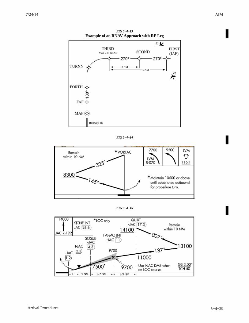
AIM4/3/14
5−4−29Arrival Procedures
FIG 5−4−13
Example of an RNAV Approach with RF Leg
FIG 5−4−14
FIG 5−4−15
7/24/14 AIM
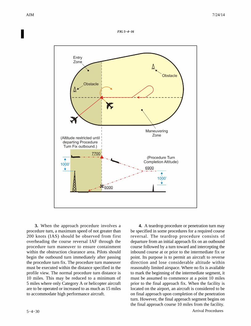
AIM 4/3/14
5−4−30 Arrival Procedures
FIG 5−4−16
3. When the approach procedure involves aprocedure turn, a maximum speed of not greater than200 knots (IAS) should be observed from firstoverheading the course reversal IAF through theprocedure turn maneuver to ensure containmentwithin the obstruction clearance area. Pilots shouldbegin the outbound turn immediately after passingthe procedure turn fix. The procedure turn maneuvermust be executed within the distance specified in theprofile view. The normal procedure turn distance is10 miles. This may be reduced to a minimum of5 miles where only Category A or helicopter aircraftare to be operated or increased to as much as 15 milesto accommodate high performance aircraft.
4. A teardrop procedure or penetration turn maybe specified in some procedures for a required coursereversal. The teardrop procedure consists ofdeparture from an initial approach fix on an outboundcourse followed by a turn toward and intercepting theinbound course at or prior to the intermediate fix orpoint. Its purpose is to permit an aircraft to reversedirection and lose considerable altitude withinreasonably limited airspace. Where no fix is availableto mark the beginning of the intermediate segment, itmust be assumed to commence at a point 10 milesprior to the final approach fix. When the facility islocated on the airport, an aircraft is considered to beon final approach upon completion of the penetrationturn. However, the final approach segment begins onthe final approach course 10 miles from the facility.
3/15/077110.65R CHG 2AIM 7/24/14

AIM4/3/14
5−4−31Arrival Procedures
5. A holding pattern in lieu of procedure turnmay be specified for course reversal in someprocedures. In such cases, the holding pattern isestablished over an intermediate fix or a finalapproach fix. The holding pattern distance or timespecified in the profile view must be observed. For ahold−in−lieu−of−PT, the holding pattern directionmust be flown as depicted and the specified leglength/timing must not be exceeded. Maximumholding airspeed limitations as set forth for allholding patterns apply. The holding pattern maneuveris completed when the aircraft is established on theinbound course after executing the appropriate entry.If cleared for the approach prior to returning to theholding fix, and the aircraft is at the prescribedaltitude, additional circuits of the holding pattern arenot necessary nor expected by ATC. If pilots elect tomake additional circuits to lose excessive altitude orto become better established on course, it is theirresponsibility to so advise ATC upon receipt of theirapproach clearance.
NOTE−Some approach charts have an arrival holding patterndepicted at the IAF using a “thin line” holding symbol. Itis charted where holding is frequently required prior tostarting the approach procedure so that detailed holdinginstructions are not required. The arrival holding patternis not authorized unless assigned by Air Traffic Control.Holding at the same fix may also be depicted on the enroutechart. A hold−in−lieu of procedure turn is depicted by a“thick line” symbol, and is part of the instrument approachprocedure as described in paragraph 5−4−9. (See U. S.Terminal Procedures booklets page E1 for both examples.)
6. A procedure turn is not required when anapproach can be made directly from a specifiedintermediate fix to the final approach fix. In suchcases, the term “NoPT” is used with the appropriatecourse and altitude to denote that the procedure turnis not required. If a procedure turn is desired, andwhen cleared to do so by ATC, descent below theprocedure turn altitude should not be made until theaircraft is established on the inbound course, sincesome NoPT altitudes may be lower than theprocedure turn altitudes.
b. Limitations on Procedure Turns
1. In the case of a radar initial approach to a finalapproach fix or position, or a timed approach from aholding fix, or where the procedure specifies NoPT,no pilot may make a procedure turn unless, when finalapproach clearance is received, the pilot so advises
ATC and a clearance is received to execute aprocedure turn.
2. When a teardrop procedure turn is depictedand a course reversal is required, this type turn mustbe executed.
3. When a holding pattern replaces a procedureturn, the holding pattern must be followed, exceptwhen RADAR VECTORING is provided or whenNoPT is shown on the approach course. Therecommended entry procedures will ensure theaircraft remains within the holding pattern’sprotected airspace. As in the procedure turn, thedescent from the minimum holding pattern altitude tothe final approach fix altitude (when lower) may notcommence until the aircraft is established on theinbound course. Where a holding pattern isestablished in−lieu−of a procedure turn, themaximum holding pattern airspeeds apply.REFERENCE−AIM, Holding, Paragraph 5−3−8j2.
4. The absence of the procedure turn barb in theplan view indicates that a procedure turn is notauthorized for that procedure.
5−4−10. Timed Approaches from a HoldingFix
a. TIMED APPROACHES may be conductedwhen the following conditions are met:
1. A control tower is in operation at the airportwhere the approaches are conducted.
2. Direct communications are maintainedbetween the pilot and the center or approachcontroller until the pilot is instructed to contact thetower.
3. If more than one missed approach procedureis available, none require a course reversal.
4. If only one missed approach procedure isavailable, the following conditions are met:
(a) Course reversal is not required; and,
(b) Reported ceiling and visibility are equalto or greater than the highest prescribed circlingminimums for the IAP.
5. When cleared for the approach, pilots mustnot execute a procedure turn. (14 CFRSection 91.175.)
b. Although the controller will not specificallystate that “timed approaches are in progress,” the
7/24/14 AIM

AIM 4/3/14
5−4−32 Arrival Procedures
assigning of a time to depart the final approach fixinbound (nonprecision approach) or the outer markeror fix used in lieu of the outer marker inbound(precision approach) is indicative that timedapproach procedures are being utilized, or in lieu ofholding, the controller may use radar vectors to theFinal Approach Course to establish a mileage intervalbetween aircraft that will ensure the appropriate timesequence between the final approach fix/outer marker
or fix used in lieu of the outer marker and the airport.
c. Each pilot in an approach sequence will be givenadvance notice as to the time they should leave theholding point on approach to the airport. When a timeto leave the holding point has been received, the pilotshould adjust the flight path to leave the fix as closelyas possible to the designated time. (See FIG 5−4−17.)
3/15/077110.65R CHG 2AIM 7/24/14
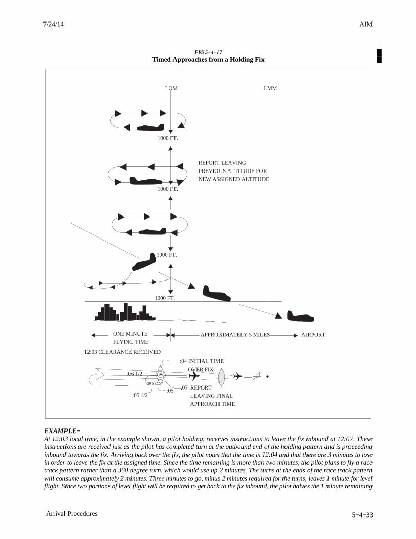
AIM4/3/14
5−4−33Arrival Procedures
FIG 5−4−17
Timed Approaches from a Holding Fix
ONE MINUTE
FLYING TIMEAPPROXIMATELY 5 MILES
12:03 CLEARANCE RECEIVED
:04 INITIAL TIME
OVER FIX
1000 FT.
1000 FT.
1000 FT.
1000 FT.
:06 1/2
:07 REPORT
LEAVING FINAL
APPROACH TIME
:05 1/2:05
30 SEC.
REPORT LEAVING
PREVIOUS ALTITUDE FOR
NEW ASSIGNED ALTITUDE
LMMLOM
AIRPORT
EXAMPLE−At 12:03 local time, in the example shown, a pilot holding, receives instructions to leave the fix inbound at 12:07. Theseinstructions are received just as the pilot has completed turn at the outbound end of the holding pattern and is proceedinginbound towards the fix. Arriving back over the fix, the pilot notes that the time is 12:04 and that there are 3 minutes to losein order to leave the fix at the assigned time. Since the time remaining is more than two minutes, the pilot plans to fly a racetrack pattern rather than a 360 degree turn, which would use up 2 minutes. The turns at the ends of the race track patternwill consume approximately 2 minutes. Three minutes to go, minus 2 minutes required for the turns, leaves 1 minute for levelflight. Since two portions of level flight will be required to get back to the fix inbound, the pilot halves the 1 minute remaining
7/24/14 AIM
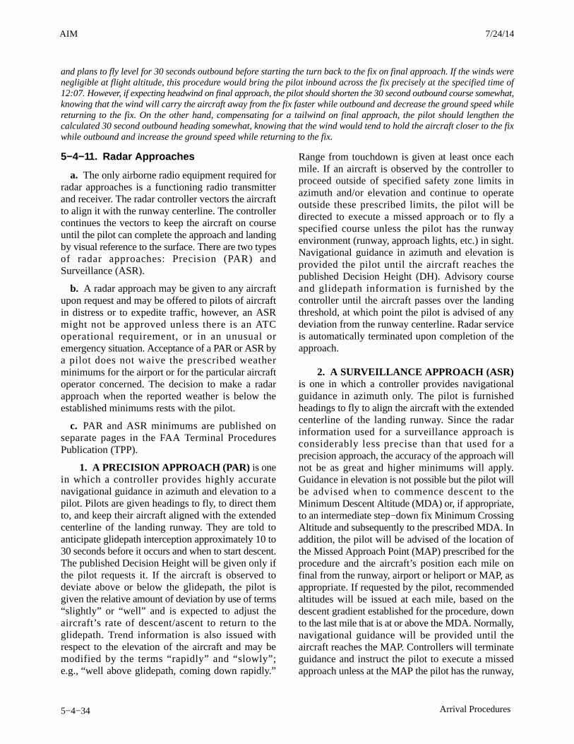
AIM 4/3/14
5−4−34 Arrival Procedures
and plans to fly level for 30 seconds outbound before starting the turn back to the fix on final approach. If the winds werenegligible at flight altitude, this procedure would bring the pilot inbound across the fix precisely at the specified time of12:07. However, if expecting headwind on final approach, the pilot should shorten the 30 second outbound course somewhat,knowing that the wind will carry the aircraft away from the fix faster while outbound and decrease the ground speed whilereturning to the fix. On the other hand, compensating for a tailwind on final approach, the pilot should lengthen thecalculated 30 second outbound heading somewhat, knowing that the wind would tend to hold the aircraft closer to the fixwhile outbound and increase the ground speed while returning to the fix.
5−4−11. Radar Approaches
a. The only airborne radio equipment required forradar approaches is a functioning radio transmitterand receiver. The radar controller vectors the aircraftto align it with the runway centerline. The controllercontinues the vectors to keep the aircraft on courseuntil the pilot can complete the approach and landingby visual reference to the surface. There are two typesof radar approaches: Precision (PAR) andSurveillance (ASR).
b. A radar approach may be given to any aircraftupon request and may be offered to pilots of aircraftin distress or to expedite traffic, however, an ASRmight not be approved unless there is an ATCoperational requirement, or in an unusual oremergency situation. Acceptance of a PAR or ASR bya pilot does not waive the prescribed weatherminimums for the airport or for the particular aircraftoperator concerned. The decision to make a radarapproach when the reported weather is below theestablished minimums rests with the pilot.
c. PAR and ASR minimums are published onseparate pages in the FAA Terminal ProceduresPublication (TPP).
1. A PRECISION APPROACH (PAR) is onein which a controller provides highly accuratenavigational guidance in azimuth and elevation to apilot. Pilots are given headings to fly, to direct themto, and keep their aircraft aligned with the extendedcenterline of the landing runway. They are told toanticipate glidepath interception approximately 10 to30 seconds before it occurs and when to start descent.The published Decision Height will be given only ifthe pilot requests it. If the aircraft is observed todeviate above or below the glidepath, the pilot isgiven the relative amount of deviation by use of terms“slightly” or “well” and is expected to adjust theaircraft’s rate of descent/ascent to return to theglidepath. Trend information is also issued withrespect to the elevation of the aircraft and may bemodified by the terms “rapidly” and “slowly”;e.g., “well above glidepath, coming down rapidly.”
Range from touchdown is given at least once eachmile. If an aircraft is observed by the controller toproceed outside of specified safety zone limits inazimuth and/or elevation and continue to operateoutside these prescribed limits, the pilot will bedirected to execute a missed approach or to fly aspecified course unless the pilot has the runwayenvironment (runway, approach lights, etc.) in sight.Navigational guidance in azimuth and elevation isprovided the pilot until the aircraft reaches thepublished Decision Height (DH). Advisory courseand glidepath information is furnished by thecontroller until the aircraft passes over the landingthreshold, at which point the pilot is advised of anydeviation from the runway centerline. Radar serviceis automatically terminated upon completion of theapproach.
2. A SURVEILLANCE APPROACH (ASR)is one in which a controller provides navigationalguidance in azimuth only. The pilot is furnishedheadings to fly to align the aircraft with the extendedcenterline of the landing runway. Since the radarinformation used for a surveillance approach isconsiderably less precise than that used for aprecision approach, the accuracy of the approach willnot be as great and higher minimums will apply.Guidance in elevation is not possible but the pilot willbe advised when to commence descent to theMinimum Descent Altitude (MDA) or, if appropriate,to an intermediate step−down fix Minimum CrossingAltitude and subsequently to the prescribed MDA. Inaddition, the pilot will be advised of the location ofthe Missed Approach Point (MAP) prescribed for theprocedure and the aircraft’s position each mile onfinal from the runway, airport or heliport or MAP, asappropriate. If requested by the pilot, recommendedaltitudes will be issued at each mile, based on thedescent gradient established for the procedure, downto the last mile that is at or above the MDA. Normally,navigational guidance will be provided until theaircraft reaches the MAP. Controllers will terminateguidance and instruct the pilot to execute a missedapproach unless at the MAP the pilot has the runway,
3/15/077110.65R CHG 2AIM 7/24/14
AIM4/3/14
5−4−35Arrival Procedures
airport or heliport in sight or, for a helicopterpoint−in−space approach, the prescribed visualreference with the surface is established. Also, if, atany time during the approach the controller considersthat safe guidance for the remainder of the approachcannot be provided, the controller will terminateguidance and instruct the pilot to execute a missedapproach. Similarly, guidance termination andmissed approach will be effected upon pilot requestand, for civil aircraft only, controllers may terminateguidance when the pilot reports the runway,airport/heliport or visual surface route(point−in−space approach) in sight or otherwiseindicates that continued guidance is not required.Radar service is automatically terminated at thecompletion of a radar approach.
NOTE−1. The published MDA for straight−in approaches will beissued to the pilot before beginning descent. When asurveillance approach will terminate in a circle−to−landmaneuver, the pilot must furnish the aircraft approachcategory to the controller. The controller will then providethe pilot with the appropriate MDA.
2. ASR APPROACHES ARE NOT AVAILABLE WHENAN ATC FACILITY IS USING CENRAP.
3. A NO−GYRO APPROACH is available toa pilot under radar control who experiencescircumstances wherein the directional gyro or otherstabilized compass is inoperative or inaccurate.When this occurs, the pilot should so advise ATC andrequest a No−Gyro vector or approach. Pilots ofaircraft not equipped with a directional gyro or otherstabilized compass who desire radar handling mayalso request a No−Gyro vector or approach. The pilotshould make all turns at standard rate and shouldexecute the turn immediately upon receipt ofinstructions. For example, “TURN RIGHT,” “STOPTURN.” When a surveillance or precision approachis made, the pilot will be advised after the aircraft hasbeen turned onto final approach to make turns at halfstandard rate.
5−4−12. Radar Monitoring of InstrumentApproaches
a. PAR facilities operated by the FAA and themilitary services at some joint−use (civil andmilitary) and military installations monitor aircrafton instrument approaches and issue radar advisoriesto the pilot when weather is below VFR minimums(1,000 and 3), at night, or when requested by a pilot.This service is provided only when the PAR FinalApproach Course coincides with the final approachof the navigational aid and only during theoperational hours of the PAR. The radar advisoriesserve only as a secondary aid since the pilot hasselected the navigational aid as the primary aid for theapproach.
b. Prior to starting final approach, the pilot will beadvised of the frequency on which the advisories willbe transmitted. If, for any reason, radar advisoriescannot be furnished, the pilot will be so advised.
c. Advisory information, derived from radarobservations, includes information on:
1. Passing the final approach fix inbound(nonprecision approach) or passing the outer markeror fix used in lieu of the outer marker inbound(precision approach).
NOTE−At this point, the pilot may be requested to report sightingthe approach lights or the runway.
2. Trend advisories with respect to elevationand/or azimuth radar position and movement will beprovided.
NOTE−Whenever the aircraft nears the PAR safety limit, the pilotwill be advised that the aircraft is well above or below theglidepath or well left or right of course. Glidepathinformation is given only to those aircraft executing aprecision approach, such as ILS. Altitude information isnot transmitted to aircraft executing other than precisionapproaches because the descent portions of theseapproaches generally do not coincide with the depictedPAR glidepath.
7/24/14 AIM
AIM 4/3/14
5−4−36 Arrival Procedures
3. If, after repeated advisories, the aircraftproceeds outside the PAR safety limit or if a radicaldeviation is observed, the pilot will be advised toexecute a missed approach unless the prescribedvisual reference with the surface is established.
d. Radar service is automatically terminated uponcompletion of the approach.
5−4−13. ILS/RNAV/GLS Approaches toParallel Runways
a. ATC procedures permit ILS/RNAV/GLSinstrument approach operations to dual or tripleparallel runway configurations. ILS/RNAV/GLSapproaches to parallel runways are grouped into threeclasses: Simultaneous Parallel DependentApproaches; Simultaneous (Parallel) IndependentApproaches; and Simultaneous Close Parallel PRMApproaches. (See FIG 5−4−18.) RNAV approachprocedures that are approved for simultaneousoperations require GPS as the sensor for positionupdating. VOR/DME, DME/DME and IRU RNAVupdating is not authorized. The classification of aparallel runway approach procedure is dependent onadjacent parallel runway centerline separation, ATCprocedures, and airport ATC radar monitoring andcommunications capabilities. At some airports one ormore parallel localizer courses may be offset up to 3degrees. ILS approaches with offset localizerconfigurations result in loss of Category II/IIIcapabilities and an increase in decisionaltitude/height (50’).
b. Parallel approach operations demandheightened pilot situational awareness. A thoroughApproach Procedure Chart review should beconducted with, as a minimum, emphasis on thefollowing approach chart information: name andnumber of the approach, localizer frequency, inboundlocalizer/azimuth course, glide slope interceptaltitude, glideslope crossing altitude at the finalapproach fix, decision height, missed approachinstructions, special notes/procedures, and theassigned runway location/proximity to adjacentrunways. Pilots will be advised that simultaneousdependent approaches, simultaneous approaches, orsimultaneous close parallel PRM approaches are inuse. This information may be provided through theATIS.
c. The close proximity of adjacent aircraftconducting simultaneous (parallel) independentapproaches and simultaneous close parallel PRMapproaches mandates strict pilot compliance with allATC clearances. ATC assigned airspeeds, altitudes,and headings must be complied with in a timelymanner. Autopilot coupled approaches require pilotknowledge of procedures necessary to comply withATC instructions. Simultaneous (parallel)independent approaches and simultaneous closeparallel PRM approaches necessitate preciseapproach course tracking to minimize final monitorcontroller intervention, and unwanted NoTransgression Zone (NTZ) penetration. In theunlikely event of a breakout, ATC will not assignaltitudes lower than the minimum vectoring altitude.Pilots should notify ATC immediately if there is adegradation of aircraft or navigation systems.
d. Strict radio discipline is mandatory duringsimultaneous (parallel) independent andsimultaneous close parallel PRM approachoperations. This includes an alert listening watch andthe avoidance of lengthy, unnecessary radiotransmissions. Attention must be given to proper callsign usage to prevent the inadvertent execution ofclearances intended for another aircraft. Use ofabbreviated call signs must be avoided to precludeconfusion of aircraft with similar sounding call signs.Pilots must be alert to unusually long periods ofsilence or any unusual background sounds in theirradio receiver. A stuck microphone may block theissuance of ATC instructions on the tower frequencyby the final monitor controller during simultaneous(parallel) independent and simultaneous closeparallel PRM approaches. In the case of PRMapproaches, the use of a second frequency by themonitor controller mitigates the “stuck mike” or otherblockage on the tower frequency.
REFERENCE−AIM, Chapter 4, Section 2, Radio Communications Phraseology andTechniques, gives additional communications information.
e. Use of Traffic Collision Avoidance Systems(TCAS) provides an additional element of safety toparallel approach operations. Pilots should followrecommended TCAS operating procedures presentedin approved flight manuals, original equipmentmanufacturer recommendations, professionalnewsletters, and FAA publications.
3/15/077110.65R CHG 2AIM 7/24/14

AIM4/3/14
5−4−37Arrival Procedures
FIG 5−4−18
Simultaneous Parallel Approaches(Parallel Runways and Approach Courses and Offset Approach Courses between 2.5 and 3.0 degrees)
7/24/14 AIM

AIM 4/3/14
5−4−38 Arrival Procedures
5−4−14. Simultaneous (Parallel) Dependent ILS/RNAV/GLS Approaches(See FIG 5−4−19.)
FIG 5−4−19
Simultaneous (Parallel) Dependent Approaches
a. Simultaneous (parallel) dependent approachesare an ATC procedure permitting approaches toairports having parallel runway centerlines separatedby between 2,500 feet and 9,000 feet. Integral partsof a total system are ILS, radar, communications,ATC procedures, and required airborne equipment.RNAV equipment in the aircraft or GLS equipmenton the ground and in the aircraft may replace therequired airborne and ground based ILS equipment.
b. A simultaneous (parallel) dependent approachdiffers from a simultaneous (parallel) independentapproach in that, the minimum distance betweenparallel runway centerlines is reduced; there is norequirement for radar monitoring or advisories; anda staggered separation of aircraft on the adjacent finalcourse is required.
c. A minimum of 1.5 NM radar separation(diagonal) is required between successive aircraft onthe adjacent final approach course when runwaycenterlines are at least 2,500 feet but no more than4,300 feet apart. When runway centerlines are morethan 4,300 feet but no more than 9,000 feet apart a
minimum of 2 NM diagonal radar separation isprovided. Aircraft on the same final approach coursecourse within 10 NM of the runway end are provideda minimum of 3 NM radar separation, reduced to2.5 NM in certain circumstances. In addition, aminimum of 1,000 feet vertical or a minimum of threemiles radar separation is provided between aircraftduring turn on to the parallel final approach course.
d. Whenever parallel approaches are in progress,pilots are informed by ATC or via the ATIS thatapproaches to both runways are in use. The chartedIAP also notes which runways may be usedsimultaneously. In addition, the radar controller willhave the interphone capability of communicatingwith the tower controller where separationresponsibility has not been delegated to the tower.
NOTE−ATC will specifically identify these operations as being de-pendent when advertised on the ATIS.
EXAMPLE−Simultaneous dependent ILS runway 19R and 19L in pro-gress.
3/15/077110.65R CHG 2AIM 7/24/14
AIM4/3/14
5−4−39Arrival Procedures
e. At certain airports, simultaneous (parallel) de-pendent approaches are permitted to runways spacedless than 2500 feet apart. In this case, ATC will stag-ger aircraft on the parallel approaches with theleaders always arriving on the same runway. Thetrailing aircraft is permitted diagonal separation ofnot less than 1.5 NM, instead of the single runwayseparation normally utilized for runways spaced lessthan 2500 feet apart. For wake turbulence mitigationreasons: a) 1.5 NM spacing is only permitted whenthe leader is either in the large or small wake turbu-lence category, and b) all aircraft must descend on theglideslope from the altitude at which they werecleared for the approach during these operations.When 1.5 NM reduced separation is authorized, the
IAP briefing strip which indicates that simultaneousoperations require the use of vertical guidance andthat the pilot should maintain last assigned altitudeuntil intercepting the glideslope. No special pilottraining is required to participate in these operations.
NOTE−Either simultaneous dependent ILS approaches or SOIALDA PRM and ILS PRM approaches may be conducted tothese runways depending on weather conditions and trafficvolume. Pilots should use caution so as not to confuse theseoperations. Use SOIA procedures only when the ATIS ad-vertises PRM approaches are in use, refer to AIMparagraph 5-4-16. SFO is the only airport where both pro-cedures are presently conducted.
7/24/14 AIM
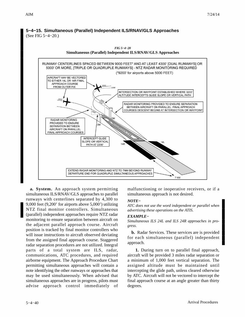
AIM 4/3/14
5−4−40 Arrival Procedures
5−4−15. Simultaneous (Parallel) Independent ILS/RNAV/GLS Approaches(See FIG 5−4−20.)
FIG 5−4−20
Simultaneous (Parallel) Independent ILS/RNAV/GLS Approaches
a. System. An approach system permittingsimultaneous ILS/RNAV/GLS approaches to parallelrunways with centerlines separated by 4,300 to9,000 feet (9,200’ for airports above 5,000’) utilizingNTZ final monitor controllers. Simultaneous(parallel) independent approaches require NTZ radarmonitoring to ensure separation between aircraft onthe adjacent parallel approach course. Aircraftposition is tracked by final monitor controllers whowill issue instructions to aircraft observed deviatingfrom the assigned final approach course. Staggeredradar separation procedures are not utilized. Integralparts of a total system are ILS, radar,communications, ATC procedures, and requiredairborne equipment. The Approach Procedure Chartpermitting simultaneous approaches will contain anote identifying the other runways or approaches thatmay be used simultaneously. When advised thatsimultaneous approaches are in progress, pilots mustadvise approach control immediately of
malfunctioning or inoperative receivers, or if asimultaneous approach is not desired.
NOTE−ATC does not use the word independent or parallel whenadvertising these operations on the ATIS.
EXAMPLE−Simultaneous ILS 24L and ILS 24R approaches in pro-gress.
b. Radar Services. These services are is providedfor each simultaneous (parallel) independentapproach.
1. During turn on to parallel final approach,aircraft will be provided 3 miles radar separation ora minimum of 1,000 feet vertical separation. Theassigned altitude must be maintained untilintercepting the glide path, unless cleared otherwiseby ATC. Aircraft will not be vectored to intercept thefinal approach course at an angle greater than thirtydegrees.
3/15/077110.65R CHG 2AIM 7/24/14

AIM4/3/14
5−4−41Arrival Procedures
2. The final monitor controller will have thecapability of overriding the tower controller on thetower frequency.
3. Pilots will be instructed to contact the towerfrequency prior to the point where NTZ monitoringbegins.
4. Aircraft observed to overshoot the turn−on orto continue on a track which will penetrate the NTZwill be instructed to return to the correct finalapproach course immediately. The final monitorcontroller may cancel the approach clearance, andissue missed approach or other instructions to thedeviating aircraft.
PHRASEOLOGY−“(Aircraft call sign) YOU HAVE CROSSED THE FINALAPPROACH COURSE. TURN (left/right)IMMEDIATELY AND RETURN TO THE FINALAPPROACH COURSE,”
or
“(aircraft call sign) TURN (left/right) AND RETURN TOTHE FINAL APPROACH COURSE.”
5. If a deviating aircraft fails to respond to suchinstructions or is observed penetrating the NTZ, theaircraft on the adjacent final approach course (ifthreatened), will be issued a breakout instruction.
PHRASEOLOGY−“TRAFFIC ALERT (aircraft call sign) TURN (left/right)IMMEDIATELY HEADING (degrees), (climb/descend)AND MAINTAIN (altitude).”
6. Radar monitoring will automatically beterminated when visual separation is applied, theaircraft reports the approach lights or runway in sight,or the aircraft is 1 mile or less from the runwaythreshold. Final monitor controllers will not advisepilots when radar monitoring is terminated.
NOTE−Simultaneous independent approaches conducted to run-ways spaced greater than 9,000 feet (or 9,200’ at airportsabove 5,000’) do not require an NTZ. However, from a pi-lot’s perspective, the same alerts relative to deviatingaircraft will be provided by ATC as are provided when anNTZ is being monitored. Pilots may not be aware as towhether or not an NTZ is being monitored.
7/24/14 AIM
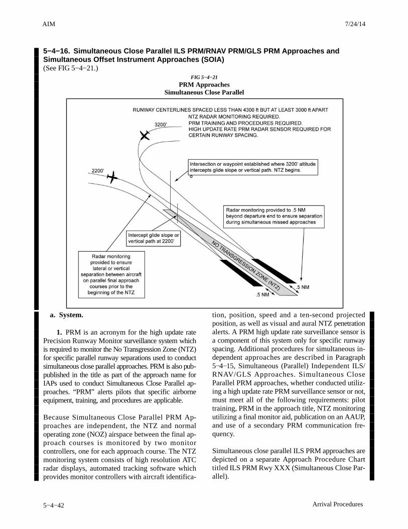
AIM 4/3/14
5−4−42 Arrival Procedures
5−4−16. Simultaneous Close Parallel ILS PRM/RNAV PRM/GLS PRM Approaches andSimultaneous Offset Instrument Approaches (SOIA)(See FIG 5−4−21.)
FIG 5−4−21
PRM ApproachesSimultaneous Close Parallel
a. System.
1. PRM is an acronym for the high update ratePrecision Runway Monitor surveillance system whichis required to monitor the No Transgression Zone (NTZ)for specific parallel runway separations used to conductsimultaneous close parallel approaches. PRM is also pub-published in the title as part of the approach name forIAPs used to conduct Simultaneous Close Parallel ap-proaches. “PRM” alerts pilots that specific airborneequipment, training, and procedures are applicable. Because Simultaneous Close Parallel PRM Ap-proaches are independent, the NTZ and normaloperating zone (NOZ) airspace between the final ap-proach courses is monitored by two monitorcontrollers, one for each approach course. The NTZmonitoring system consists of high resolution ATCradar displays, automated tracking software whichprovides monitor controllers with aircraft identifica-
tion, position, speed and a ten-second projectedposition, as well as visual and aural NTZ penetrationalerts. A PRM high update rate surveillance sensor isa component of this system only for specific runwayspacing. Additional procedures for simultaneous in-dependent approaches are described in Paragraph5−4−15, Simultaneous (Parallel) Independent ILS/RNAV/GLS Approaches. Simultaneous CloseParallel PRM approaches, whether conducted utiliz-ing a high update rate PRM surveillance sensor or not,must meet all of the following requirements: pilottraining, PRM in the approach title, NTZ monitoringutilizing a final monitor aid, publication on an AAUP,and use of a secondary PRM communication fre-quency. Simultaneous close parallel ILS PRM approaches aredepicted on a separate Approach Procedure Charttitled ILS PRM Rwy XXX (Simultaneous Close Par-allel).
3/15/077110.65R CHG 2AIM 7/24/14
AIM4/3/14
5−4−43Arrival Procedures
NOTE−ATC does not use the word “independent” when advert-ising these operations on the ATIS.
EXAMPLE−Simultaneous ILS PRM 33L and ILS PRM 33R approachesin progress.
(a) In the discussion below, RNAV PRM andGLS PRM approaches may be substituted for one orboth of the ILS PRM approaches in a simultaneousclose parallel operation, or, in the case of SOIA, maybe substituted for an ILS PRM and/or LDA PRM ap-proach. RNAV PRM or GLS PRM approaches utilizethe same applicable chart notations and the samefixes, crossing altitudes, and missed approach pro-cedures as the ILS PRM or LDA PRM approach itoverlays. Vertical guidance for an RNAV PRM orGLS PRM approach must be used when substitutingfor an ILS PRM or LDA PRM approach.
(b) RNAV PRM and GLS PRM approachesmay be substituted for:
(1) one or both of the ILS PRM approachesin a simultaneous close parallel operation, or
(2) the ILS PRM and/or LDA PRM ap-proach in a Simultaneous Offset InstrumentApproach (SOIA) operation.
(c) The pilot may request to fly the RNAVPRM or GLS PRM approach in lieu of either the ILSPRM and LDA PRM approaches. ATIS may advert-ise RNAV or GLS PRM approaches to the effectedrunway or runways in the event of the loss of groundbased NAVAIDS. The Attention All Users Page willaddress ILS PRM, LDA PRM, RNAV PRM, or GLSPRM approaches as applicable. In the remainder ofthis section:
(1) The RNAV PRM or GLS PRM ap-proaches may be substituted when reference is madeto an ILS, LOC, or SOIA offset LDA PRM approach.
(2) The RNAV PRM or GLS PRM MissedApproach Point (MAP) in SOIA operations may besubstituted when reference is made to the LDA PRMMAP.
2. Flight Management System (FMS) coding ofthe offset RNAV PRM and GLS PRM approaches ina SOIA operation is different than other RNAV andGLS approach coding in that it does not match the ini-tial procedure published on the charted IAP. In the
SOIA design of the offset approach, the lateral courseterminates at the fictitious threshold point (FTP),which is an extension of the final approach course toa point near the runway threshold. The FTP is desig-nated in the approach coding as the MAP so thatvertical guidance is available to the pilot to the run-way threshold, just as vertical guidance is providedby the LDA glideslope. RNAV and GLS lateral guid-ance, in contrast, is discontinued at the charted MAPand replaced by visual maneuvering to accomplishrunway alignment in the same manner as LDA courseguidance is discontinued at the MAP. As a result of this RNAV and GLS approach coding,when executing a missed approach at and afterpassing the charted MAP, a heading must initially beflown, either hand-flown or using autopilot “headingmode,” before engaging LNAV. If the pilot engagesLNAV immediately, the aircraft will continue to tracktoward the FTP instead of commencing a turn towardthe missed approach holding fix. Notes on the chartedIAP and in the AAUP make specific reference to thisprocedure. Because the SOIA LDA approach is coded in theFMS in same manner as the RNAV GPS approach,this same procedure should be utilized when conduct-ing the LDA PRM missed approach at or inside of theLDA MAP. Some FMSs do not code waypoints inside of the FAFas part of the approach. Therefore, the depicted MAPon the charted IAP may not be included in the offsetapproach coding. Pilots utilizing those FMSs mayidentify the location of the waypoint by noting its dis-tance from the FTP as published on the charted IAP.In those same FMSs, the straight-in SOIA approachwill not display a waypoint inside the PFAF. Thesame procedures may be utilized to identify the un-coded waypoint. In this case, the location isdetermined by noting its distance from the runwaywaypoint as published on the charted IAP. Because the FTP is coded as the MAP, the FMS mapdisplay will depict the initial missed approach courseas beginning at the FTP. This depiction does notmatch the charted initial missed approach procedureon the IAP. Pilots are reminded that charted IAP guid-ance is to be followed, not the map display. Once theaircraft completes the initial turn when commencing
7/24/14 AIM

AIM 4/3/14
5−4−44 Arrival Procedures
a missed approach, the remainder of the procedurecoding is standard and can be utilized as with any oth-er IAP.
b. Simultaneous Offset Instrument Approach(SOIA).
1. SOIA is an acronym for Simultaneous OffsetInstrument Approach, a procedure used to conductsimultaneous approaches to runways spaced less than3,000 feet, but at least 750 feet apart. The SOIA pro-cedure utilizes an ILS PRM approach to one runwayand an offset Localizer Type Directional Aid (LDA)PRM approach with glide slope to the adjacent run-way. In SOIA operations, aircraft are paired, with theaircraft conducting the ILS PRM approach alwayspositioned slightly ahead of the aircraft conductingthe LDA PRM approach.
2. The ILS PRM approach plates used in SOIAoperations are identical to other ILS PRM approachplates, with an additional note, which provides theseparation between the two runways used for simul-taneous approaches. The LDA PRM approach platedisplays the required notations for closely spaced ap-proaches as well as depicting the visual segment ofthe approach.
3. Controllers monitor the SOIA ILS PRM andLDA PRM approaches in exactly the same manner asis done for ILS PRM approaches. The procedures andsystem requirements for SOIA ILS PRM and LDAPRM approaches are identical with those used forsimultaneous close parallel ILS PRM approaches un-til near the LDA PRM approach missed approachpoint (MAP) −− where visual acquisition of the ILSaircraft by the aircraft conducting the LDA PRM ap-proach occurs. Since the ILS PRM and LDA PRMapproaches are identical except for the visual segmentin the SOIA concept, an understanding of the proced-ures for conducting ILS PRM approaches is essentialbefore conducting a SOIA ILS PRM or LDA PRMoperation.
4. In SOIA, the approach course separation (in-stead of the runway separation) meets establishedclose paral lel approach cr i ter ia. Refer toFIG 5−4−22 for the generic SOIA approach geo-metry. A visual segment of the LDA PRM approachis established between the LDA MAP and the runwaythreshold. Aircraft transition in visual conditionsfrom the LDA course, beginning at the LDA MAP, toalign with the runway and can be stabilized by 500
feet above ground level (AGL) on the extended run-way centerline. Aircraft will be “paired” in SOIAoperations, with the ILS aircraft ahead of the LDAaircraft prior to the LDA aircraft reaching the LDAMAP. A cloud ceiling for the approach is establishedso that the LDA aircraft has nominally 30 seconds toacquire the leading ILS aircraft prior to the LDA air-craft reaching the LDA MAP. If visual acquisition isnot accomplished, a missed approach must be ex-ecuted at the LDA MAP.
c. Requirements and Procedures.
Besides system requirements and pilot procedures asidentified in subparagraph a1 above, all pilots musthave completed special training before accepting aclearance to conduct ILS PRM or LDA PRM Simul-taneous Close Parallel Approaches.
1. Pilot Training Requirement. Pilots mustcomplete special pilot training, as outlined below,before accepting a clearance for a simultaneous closeparallel ILS PRM or LDA PRM approach.
(a) For operations under 14 CFR Parts 121,129, and 135, pilots must comply with FAA−ap-proved company training as identified in theirOperations Specifications. Training, at a minim-um, must require pilots to view the FAA video“ILS PRM AND SOIA APPROACHES: INFORM-ATION FOR AIR CARRIER PILOTS.” Refer tohttps://www.faa.gov/training_testing/training/prm/ or search key words FAA PRM foradditional information and to view or download thevideo.
(b) For operations under Part 91:
(1) Pilots operating transport categoryaircraft must be familiar with PRM operations as con-tained in this section of the AIM. In addition, pilotsoperating transport category aircraft must viewthe FAA video “ILS PRM AND SOIAAPPROACHES: INFORMATION FOR AIRCARRIER PILOTS.” Refer to https://www.faa.gov/training_testing/training/prm/ or search keywords FAA PRM for additional information and toview or download the video.
(2) Pilots not operating transport cat-egory aircraft must be familiar with PRM and SOIAoperations as contained in this section of the AIM.The FAA strongly recommends that pilots not in-volved in transport category aircraft operationsview the FAA video, “ILS PRM AND SOIA AP-
3/15/077110.65R CHG 2AIM 7/24/14
AIM4/3/14
5−4−45Arrival Procedures
PROACHES: INFORMATION FOR GENERALAVIATION PILOTS.” Refer tohttps://www.faa.gov/training_testing/training/prm/ or search key words FAA PRM foradditional information and to view or download thevideo.
NOTE−Either simultaneous dependent ILS approaches, or SOIALDA PRM and ILS PRM approaches may be conducted de-pending on weather conditions and traffic volume. Pilotsshould use caution so as not to confuse these operations.Use SOIA procedures only when the ATIS advertises PRMapproaches are in use. For simultaneous (parallel) de-pendent approaches see paragraph 5−4−14. SFO is theonly airport where both procedures are presently conduc-ted.
2. ATC Directed Breakout. An ATC directed“breakout” is defined as a vector off the ILS or LDAapproach course of a threatened aircraft in response toanother aircraft penetrating the NTZ.
3. Dual Communications. The aircraft flyingthe ILS PRM or LDA PRM approach must have thecapability of enabling the pilot/s to listen to two com-munications frequencies simultaneously.
4. Radar Services.
(a) During turn on to parallel final approach,aircraft will be provided 3 miles radar separation ora minimum or 1,000 feet vertical separation. The as-signed altitude must be maintained until interceptingthe glide path, unless cleared otherwise by ATC. Air-craft will not be vectored to intercept the finalapproach course at an angle greater than thirty de-grees.
(b) The final monitor controller will have thecapability of overriding the tower controller on thetower frequency.
(c) Pilots will be instructed to contact thetower frequency prior to the point where NTZ monit-oring begins. Pilots will begin monitoring thesecondary PRM frequency at that time (see DualVHF Communications Required below).
(d) To ensure separation is maintained, and inorder to avoid an imminent situation during simultan-eous close parallel ILS PRM or SOIA ILS PRM andLDA PRM approaches, pilots must immediately com-ply with PRM monitor controller instructions.
(e) Aircraft observed to overshoot the turn−on or to continue on a track which will penetrate theNTZ will be instructed to return to the correct finalapproach course immediately. The final monitor con-troller may cancel the approach clearance, and issuemissed approach or other instructions to the deviatingaircraft.
PHRASEOLOGY−“(Aircraft call sign) YOU HAVE CROSSED THE FINALAPPROACH COURSE. TURN (left/right) IMMEDI-ATELY AND RETURN TO THE LOCALIZER FINALAPPROACH COURSE,”or“(aircraft call sign) TURN (left/right) AND RETURN TOTHE LOCALIZER FINAL APPROACH COURSE.”
(f) If a deviating aircraft fails to respond tosuch instructions or is observed penetrating the NTZ,the aircraft on the adjacent final approach course (ifthreatened) will be issued a breakout instruction.
PHRASEOLOGY−“TRAFFIC ALERT (aircraft call sign) TURN (left/right)IMMEDIATELY HEADING (degrees), (climb/descend)AND MAINTAIN (altitude).”
(g) Radar monitoring will automatically beterminated when visual separation is applied or theaircraft reports the approach lights or runway insight. Otherwise, monitoring continues to at least.5 NM beyond the furthest DER. Final monitor con-trollers will not advise pilots when radar monitoringis terminated.
5. At airports that conduct PRM operations,(ILS PRM, and the case of airports where SOIAs areconducted, ILS PRM and LDA PRM approaches) theAttention All Users Page (AAUP) informs pilots whoare unable to participate that they will be afforded ap-propriate arrival services as operational conditionspermit and must notify the controlling ARTCC assoon as practical, but at least 100 miles from destina-tion.
7/24/14 AIM
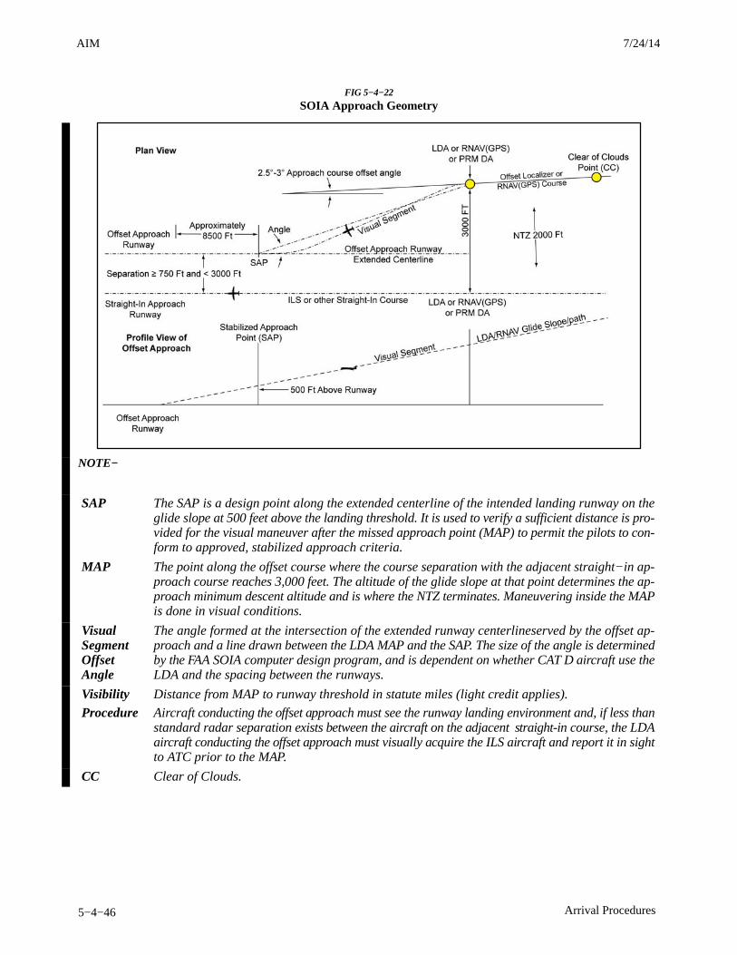
AIM 4/3/14
5−4−46 Arrival Procedures
FIG 5−4−22
SOIA Approach Geometry
NOTE−
SAP The SAP is a design point along the extended centerline of the intended landing runway on theglide slope at 500 feet above the landing threshold. It is used to verify a sufficient distance is pro-vided for the visual maneuver after the missed approach point (MAP) to permit the pilots to con-form to approved, stabilized approach criteria.
MAP The point along the offset course where the course separation with the adjacent straight−in ap-proach course reaches 3,000 feet. The altitude of the glide slope at that point determines the ap-proach minimum descent altitude and is where the NTZ terminates. Maneuvering inside the MAPis done in visual conditions.
VisualSegmentOffsetAngle
The angle formed at the intersection of the extended runway centerlineserved by the offset ap-proach and a line drawn between the LDA MAP and the SAP. The size of the angle is determinedby the FAA SOIA computer design program, and is dependent on whether CAT D aircraft use theLDA and the spacing between the runways.
Visibility Distance from MAP to runway threshold in statute miles (light credit applies).
Procedure Aircraft conducting the offset approach must see the runway landing environment and, if less thanstandard radar separation exists between the aircraft on the adjacent straight-in course, the LDAaircraft conducting the offset approach must visually acquire the ILS aircraft and report it in sightto ATC prior to the MAP.
CC Clear of Clouds.
3/15/077110.65R CHG 2AIM 7/24/14
AIM4/3/14
5−4−47Arrival Procedures
d. Attention All Users Page (AAUP). MultiplePRM approach charts at the same airport have a singleAAUP associated with them that must be referred toin preparation for conducting the approach.
Bullet points are published which summarize thePRM procedures which apply to each approach andmust be briefed before conducting a PRM approach.The following information may be summarized in thebullet points or published in more detail in the Expan-ded Procedures section of the AAUP. Briefing on theExpanded Procedures is optional.
1. ATIS. When the ATIS broadcast advises ILSPRM approaches are in progress (or ILS PRM andLDA PRM approaches in the case of SOIA), pilotsshould brief to fly the ILS PRM or LDA PRM ap-proach. If later advised to expect the ILS or LDAapproach (should one be published), the ILS PRM orLDA PRM chart may be used after completing thefollowing briefing items. The pilot may also requestto fly the RNAV (GPS) PRM in lieu of either the ILSPRM or LDAPRM approach. In the event of the lossof ground based NAVAIDS, the ATIS may advertiseRNAV (GPS) PRM approaches to the effected run-way or runways.
(a) Minimums and missed approach proced-ures are unchanged.
(b) PRM Monitor frequency no longer re-quired.
(c) ATC may assign a lower altitude for glideslope intercept.
NOTE−In the case of the LDA PRM approach, this briefing proced-ure only applies if an LDA-DME approach is alsopublished.
In the case of the SOIA ILS PRM and LDA PRM pro-cedure, the AAUP describes the weather conditionsin which simultaneous approaches are authorized:
Simultaneous approach weather minimums areX,XXX feet (ceiling), x miles (visibility).
2. Dual VHF Communications Required.To avoid blocked transmissions, each runway willhave two frequencies, a primary and a PRM monitorfrequency. The tower controller will transmit on bothfrequencies. The monitor controller’s transmissions,if needed, will override both frequencies. Pilots willONLY transmit on the tower controller’s frequency,but will listen to both frequencies. Select the PRM
monitor frequency audio only when instructed byATC to contact the tower. The volume levels shouldbe set about the same on both radios so that the pilotswill be able to hear transmissions on at least one fre-quency if the other is blocked. Site specificprocedures take precedence over the general informa-tion presented in this paragraph. Refer to the AAUPfor applicable procedures at specific airports.
NOTE−At SFO, pilots conducting SOIA operations select the mon-itor frequency audio when communicating with the finalradar controller. In this special case, the monitor control-ler’s transmissions, if required, override the finalcontroller’s frequency.
3. Breakouts. Breakouts differ from other typesof abandoned approaches in that they can happenanywhere and unexpectedly. Pilots directed by ATCto break off an approach must assume that an aircraftis blundering toward them and a breakout must be ini-tiated immediately.
(a) Hand-fly breakouts. All breakouts areto be hand-flown to ensure the maneuver is accom-plished in the shortest amount of time.
(b) ATC Directed “Breakouts.” ATC dir-ected breakouts will consist of a turn and a climb ordescent. Pilots must always initiate the breakout in re-sponse to an air traffic controller’s instruction.Controllers will give a descending breakout onlywhen there are no other reasonable options available,but in no case will the descent be below the minimumvectoring altitude (MVA) which provides at least1,000 feet required obstruction clearance. TheAAUP may provide the MVA in the final approachsegment as X,XXX feet at (Name) Airport.
NOTE−“TRAFFIC ALERT.” If an aircraft enters the “NO TRANS-GRESSION ZONE (NTZ),” the controller will breakout thethreatened aircraft on the adjacent approach. The phraseo-logy for the breakout will be:
PHRASEOLOGY−TRAFFIC ALERT, (aircraft call sign) TURN (left/right)IMMEDIATELY, HEADING (degrees), CLIMB/ DES-CEND AND MAINTAIN (altitude).
4. ILS PRM Glideslope Navigation. The pilotmay find crossing altitudes published along the finalapproach course. If the approach geometry warrantsit, the pilot is advised on the AAUP that descendingon the ILS or LDA glideslope ensures complyingwith any charted crossing restrictions.
7/24/14 AIM
AIM 4/3/14
5−4−48 Arrival Procedures
5. SOIA and ILS PRM differences as notedon the AAUP.
(a) ILS PRM, LDA Traffic (only publishedon the AAUP when the ILS PRM approach is usedin conjunction with an LDA PRM approach to theadjacent runway). To provide better situationalawareness, and because traffic on the LDA may bevisible on the ILS aircraft’s TCAS, pilots are re-minded of the fact that aircraft will be maneuveringbehind them to align with the adjacent runway. Whileconducting the ILS PRM approach to Runway XXX,other aircraft may be conducting the offset LDA PRMapproach to Runway XXX. These aircraft will ap-proach from the (left/right) rear and will realign withRunway XXX after making visual contact with theILS traffic. Under normal circumstances, these air-craft will not pass the ILS traffic.
(b) SOIA LDA PRM Items. The AAUP sec-tion for the SOIA LDA PRM approach contains mostinformation found in the ILS PRM section. It replacescertain information as seen below and provides pilotswith the procedures to be used in the visual segmentof the LDA PRM approach from the LDA MAP untillanding.
(c) SOIA LDA PRM Navigation (replacesILS PRM (4) and (a) above). The pilot may findcrossing altitudes published along the final approachcourse. The pilot is advised that descending on theLDA glideslope ensures complying with any chartedcrossing restrictions. Remain on the LDA course un-til passing XXXXX (LDA MAP name) intersectionprior to maneuvering to align with the centerline ofRunway XXX.
(d) SOIA (Name) Airport Visual Segment(replaces ILS PRM (4) above). Pilot procedures fornavigating beyond the LDA MAP are spelled out. IfATC advises that there is traffic on the adjacent ILS,pilots are authorized to continue past the LDA MAPto align with runway centerline when:
(1) the ILS traffic is in sight and is expectedto remain in sight,
(2) ATC has been advised that “traffic is insight.” (ATC is not required to acknowledge thistransmission),
(3) the runway environment is in sight.Otherwise, a missed approach must be executed.Between the LDA MAP and the runway threshold, pi-
lots conducting the LDA PRM approach are re-sponsible for separating themselves visually fromtraffic conducting the ILS PRM approach to the adja-cent runway, which means maneuvering the aircraftas necessary to avoid that traffic until landing, andproviding wake turbulence avoidance, if applicable.Pilots maintaining visual separation should adviseATC, as soon as practical, if visual contact with theaircraft conducting the ILS PRM approach is lost andexecute a missed approach unless otherwise instruc-ted by ATC.
e. Differences between Simultaneous ILS andILS PRM or LDA PRM approaches of import-ance to the pilot.
1. Runway Spacing. Prior to simultaneousclose parallel approaches, most ATC directed break-outs were the result of two aircraft in-trail on the samefinal approach course getting too close together. Twoaircraft going in the same direction did not mandatequick reaction times. With PRM closely spaced ap-proaches, two aircraft could be alongside each other,navigating on courses that are separated by less than4,300 feet. In the unlikely event that an aircraft “blun-ders” off its course and makes a worst case turn of 30degrees toward the adjacent final approach course,closing speeds of 135 feet per second could occur thatconstitute the need for quick reaction. A blunder hasto be recognized by the monitor controller, andbreakout instructions issued to the endangered air-craft. The pilot will not have any warning that abreakout is imminent because the blundering air-craft will be on another frequency. It is importantthat, when a pilot receives breakout instructions, he/she assumes that a blundering aircraft is about to orhas penetrated the NTZ and is heading toward his/herapproach course. The pilot must initiate a breakoutas soon as safety allows. While conducting PRM ap-proaches, pilots must maintain an increased sense ofawareness in order to immediately react to an ATC in-struction (breakout) and maneuver as instructed byATC, away from a blundering aircraft.
2. Communications. To help in avoiding com-munication problems caused by stuck microphonesand two parties talking at the same time, two frequen-cies for each runway will be in use during ILS PRMand LDA PRM approach operations, the primarytower frequency and the PRM monitor frequency.The tower controller transmits and receive in a nor-mal fashion on the primary frequency and alsotransmits on the PRM monitor frequency. The monit-
3/15/077110.65R CHG 2AIM 7/24/14
AIM4/3/14
5−4−49Arrival Procedures
or controller’s transmissions override on bothfrequencies. The pilots flying the approach will listento both frequencies but only transmit on the primarytower frequency. If the PRM monitor controller initi-ates a breakout and the primary frequency is blockedby another transmission, the breakout instruction willstill be heard on the PRM monitor frequency.
NOTE−At some airports, the override capability may be on otherthan the tower frequency (KSFO overrides the final radarcontroller frequency). Pilots should carefully review thedual communications requirements on the AAUP prior toaccepting a PRM approach.
3. Breakouts. The probability is extremelylow that an aircraft will “blunder” from its assignedapproach course and enter the NTZ, causing ATC to“breakout” the aircraft approaching on the adjacentILS or LDA course. However, because of the closeproximity of the final approach courses, it is essentialthat pilots follow the ATC breakout instructions pre-cisely and expeditiously. The controller’s “breakout”instructions provide conflict resolution for thethreatened aircraft, with the turn portion of the“breakout” being the single most important elementin achieving maximum protection. A descendingbreakout will only be issued when it is the only con-troller option. In no case will the controller descendan aircraft below the MVA, which will provide at least1,000 feet clearance above obstacles. The pilot is notexpected to exceed 1,000 feet per minute rate of des-cent in the event a descending breakout is issued.
4. Hand-flown Breakouts. The use of theautopilot is encouraged while flying an ILS PRM orLDA PRM approach, but the autopilot must be disen-gaged in the rare event that a breakout is issued.Simulation studies of breakouts have shown that ahand-flown breakout can be initiated consistentlyfaster than a breakout performed using the autopilot.
5. TCAS. The ATC breakout instruction is theprimary means of conflict resolution. TCAS, if in-stalled, provides another form of conflict resolutionin the unlikely event other separation standardswould fail. TCAS is not required to conduct a closelyspaced approach.
The TCAS provides only vertical resolution of air-craft conflicts, while the ATC breakout instructionprovides both vertical and horizontal guidance forconflict resolutions. Pilots should always immedi-ately follow the TCAS Resolution Advisory (RA),
whenever it is received. Should a TCAS RA be re-ceived before, during, or after an ATC breakoutinstruction is issued, the pilot should follow the RA,even if it conflicts with the climb/descent portion ofthe breakout maneuver. If following an RA requiresdeviating from an ATC clearance, the pilot must ad-vise ATC as soon as practical. While following anRA, it is extremely important that the pilot alsocomply with the turn portion of the ATC breakout in-struction unless the pilot determines safety to befactor. Adhering to these procedures assures the pilotthat acceptable “breakout” separation margins willalways be provided, even in the face of a normal pro-cedural or system failure.
5−4−17. Simultaneous ConvergingInstrument Approaches
a. ATC may conduct instrument approachessimultaneously to converging runways; i.e., runwayshaving an included angle from 15 to 100 degrees, atairports where a program has been specificallyapproved to do so.
b. The basic concept requires that dedicated,separate standard instrument approach procedures bedeveloped for each converging runway included.Missed Approach Points must be at least 3 miles apartand missed approach procedures ensure that missedapproach protected airspace does not overlap.
c. Other requirements are: radar availability,nonintersecting final approach courses, precisionapproach capability for each runway and, if runwaysintersect, controllers must be able to apply visualseparation as well as intersecting runway separationcriteria. Intersecting runways also require minimumsof at least 700 foot ceilings and 2 miles visibility.Straight in approaches and landings must be made.
d. Whenever simultaneous convergingapproaches are in progress, aircraft will be informedby the controller as soon as feasible after initialcontact or via ATIS. Additionally, the radar controllerwill have direct communications capability with thetower controller where separation responsibility hasnot been delegated to the tower.
5−4−18. RNP AR Instrument ApproachProcedures
These procedures require authorization analogous tothe special authorization required for Category II orIII ILS procedures. Authorization required (AR)procedures are to be conducted by aircrews meeting
7/24/14 AIM
AIM 4/3/14
5−4−50 Arrival Procedures
special training requirements in aircraft that meet thespecified performance and functional requirements.
a. Unique characteristics of RNP ARApproaches
1. RNP value. Each published line of minimahas an associated RNP value. The indicated valuedefines the lateral and vertical performancerequirements. A minimum RNP type is documentedas part of the RNP AR authorization for each operatorand may vary depending on aircraft configuration oroperational procedures (e.g., GPS inoperative, use offlight director vice autopilot).
2. Curved path procedures. Some RNPapproaches have a curved path, also called aradius−to−a−fix (RF) leg. Since not all aircraft havethe capability to fly these arcs, pilots are responsiblefor knowing if they can conduct an RNP approachwith an arc or not. Aircraft speeds, winds and bankangles have been taken into consideration in thedevelopment of the procedures.
3. RNP required for extraction or not.Where required, the missed approach procedure mayuse RNP values less than RNP−1. The reliability ofthe navigation system has to be very high in order toconduct these approaches. Operation on theseprocedures generally requires redundant equipment,as no single point of failure can cause loss of bothapproach and missed approach navigation.
4. Non−standard speeds or climb gradients.RNP AR approaches are developed based on standardapproach speeds and a 200 ft/NM climb gradient inthe missed approach. Any exceptions to thesestandards will be indicated on the approachprocedure, and the operator should ensure they cancomply with any published restrictions beforeconducting the operation.
5. Temperature Limits. For aircraft usingbarometric vertical navigation (without temperaturecompensation) to conduct the approach, low andhigh−temperature limits are identified on theprocedure. Cold temperatures reduce the glidepathangle while high temperatures increase the glidepathangle. Aircraft using baro VNAV with temperaturecompensation or aircraft using an alternate means forvertical guidance (e.g., SBAS) may disregard thetemperature restrictions. The charted temperaturelimits are evaluated for the final approach segmentonly. Regardless of charted temperature limits ortemperature compensation by the FMS, the pilot mayneed to manually compensate for cold temperature onminimum altitudes and the decision altitude.
6. Aircraft size. The achieved minimums maybe dependent on aircraft size. Large aircraft mayrequire higher minimums due to gear height and/orwingspan. Approach procedure charts will beannotated with applicable aircraft size restrictions.
3/15/077110.65R CHG 2AIM 7/24/14
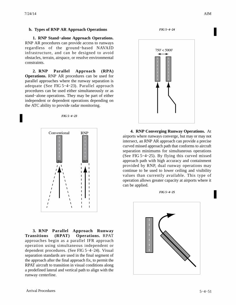
AIM4/3/14
5−4−51Arrival Procedures
b. Types of RNP AR Approach Operations
1. RNP Stand−alone Approach Operations.RNP AR procedures can provide access to runwaysregardless of the ground−based NAVAIDinfrastructure, and can be designed to avoidobstacles, terrain, airspace, or resolve environmentalconstraints.
2. RNP Parallel Approach (RPA)Operations. RNP AR procedures can be used forparallel approaches where the runway separation isadequate (See FIG 5−4−23). Parallel approachprocedures can be used either simultaneously or asstand−alone operations. They may be part of eitherindependent or dependent operations depending onthe ATC ability to provide radar monitoring.
FIG 5−4−23
3. RNP Parallel Approach RunwayTransitions (RPAT) Operations. RPATapproaches begin as a parallel IFR approachoperation using simultaneous independent ordependent procedures. (See FIG 5−4−24). Visualseparation standards are used in the final segment ofthe approach after the final approach fix, to permit theRPAT aircraft to transition in visual conditions alonga predefined lateral and vertical path to align with therunway centerline.
FIG 5−4−24
4. RNP Converging Runway Operations. Atairports where runways converge, but may or may notintersect, an RNP AR approach can provide a precisecurved missed approach path that conforms to aircraftseparation minimums for simultaneous operations(See FIG 5−4−25). By flying this curved missedapproach path with high accuracy and containmentprovided by RNP, dual runway operations maycontinue to be used to lower ceiling and visibilityvalues than currently available. This type ofoperation allows greater capacity at airports where itcan be applied.
FIG 5−4−25
7/24/14 AIM
AIM 4/3/14
5−4−52 Arrival Procedures
5−4−19. Side−step Maneuver
a. ATC may authorize a standard instrumentapproach procedure which serves either one ofparallel runways that are separated by 1,200 feet orless followed by a straight−in landing on the adjacentrunway.
b. Aircraft that will execute a side−step maneuverwill be cleared for a specified approach procedureand landing on the adjacent parallel runway.Example, “cleared ILS runway 7 left approach,side−step to runway 7 right.” Pilots are expected tocommence the side−step maneuver as soon aspossible after the runway or runway environment isin sight. Compliance with minimum altitudesassociated with stepdown fixes is expected even afterthe side−step maneuver is initiated.NOTE−Side−step minima are flown to a Minimum DescentAltitude (MDA) regardless of the approach authorized.
c. Landing minimums to the adjacent runway willbe based on nonprecision criteria and therefore higherthan the precision minimums to the primary runway,but will normally be lower than the published circlingminimums.
5−4−20. Approach and Landing Minimums
a. Landing Minimums. The rules applicable tolanding minimums are contained in 14 CFRSection 91.175. TBL 5−4−1 may be used to convertRVR to ground or flight visibility. For convertingRVR values that fall between listed values, use thenext higher RVR value; do not interpolate. Forexample, when converting 1800 RVR, use 2400 RVRwith the resultant visibility of 1/2 mile.
b. Obstacle Clearance. Final approach obstacleclearance is provided from the start of the finalsegment to the runway or missed approach point,whichever occurs last. Side−step obstacle protectionis provided by increasing the width of the finalapproach obstacle clearance area.
TBL 5−4−1
RVR Value ConversionsRVR Visibility
(statute miles)1600 1/42400 1/23200 5/84000 3/44500 7/85000 16000 1 1/4
1. Circling approach protected areas are definedby the tangential connection of arcs drawn from eachrunway end (see FIG 5−4−26). Circling approachprotected areas developed prior to late 2012 usedfixed radius distances, dependent on aircraftapproach category, as shown in the table on page B2of the U.S. TPP. The approaches using standardcircling approach areas can be identified by theabsence of the “negative C” symbol on the circlingline of minima. Circling approach protected areasdeveloped after late 2012 use the radius distanceshown in the table on page B2 of the U.S. TPP,dependent on aircraft approach category, and thealtitude of the circling MDA, which accounts for trueairspeed increase with altitude. The approaches usingexpanded circling approach areas can be identified bythe presence of the “negative C” symbol on thecircling line of minima (see FIG 5−4−27). Because ofobstacles near the airport, a portion of the circlingarea may be restricted by a procedural note; forexample, “Circling NA E of RWY 17−35.” Obstacleclearance is provided at the published minimums(MDA) for the pilot who makes a straight−inapproach, side−steps, or circles. Once below theMDA the pilot must see and avoid obstacles.Executing the missed approach after starting tomaneuver usually places the aircraft beyond theMAP. The aircraft is clear of obstacles when at orabove the MDA while inside the circling area, butsimply joining the missed approach ground trackfrom the circling maneuver may not provide verticalobstacle clearance once the aircraft exits the circlingarea. Additional climb inside the circling area may berequired before joining the missed approach track.See Paragraph 5−4−21, Missed Approach, foradditional considerations when starting a missedapproach at other than the MAP.
3/15/077110.65R CHG 2AIM 7/24/14
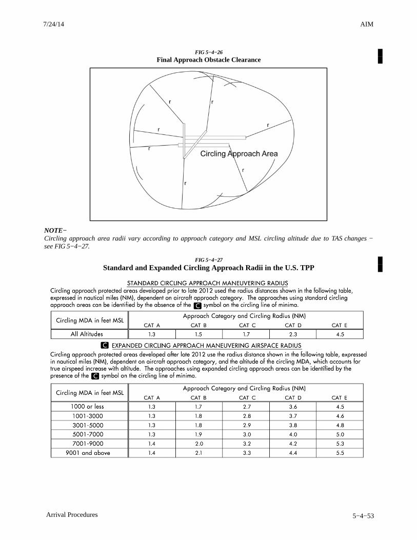
AIM4/3/14
5−4−53Arrival Procedures
FIG 5−4−26
Final Approach Obstacle Clearance
NOTE−Circling approach area radii vary according to approach category and MSL circling altitude due to TAS changes −see FIG 5−4−27.
FIG 5−4−27
Standard and Expanded Circling Approach Radii in the U.S. TPP
7/24/14 AIM
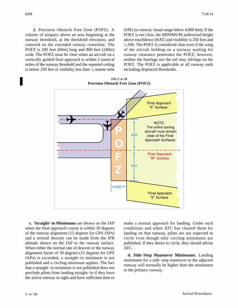
AIM 4/3/14
5−4−54 Arrival Procedures
2. Precision Obstacle Free Zone (POFZ). Avolume of airspace above an area beginning at therunway threshold, at the threshold elevation, andcentered on the extended runway centerline. ThePOFZ is 200 feet (60m) long and 800 feet (240m)wide. The POFZ must be clear when an aircraft on avertically guided final approach is within 2 nauticalmiles of the runway threshold and the reported ceilingis below 250 feet or visibility less than 3/4 statute mile
(SM) (or runway visual range below 4,000 feet). If thePOFZ is not clear, the MINIMUM authorized heightabove touchdown (HAT) and visibility is 250 feet and3/4 SM. The POFZ is considered clear even if the wingof the aircraft holding on a taxiway waiting forrunway clearance penetrates the POFZ; however,neither the fuselage nor the tail may infringe on thePOFZ. The POFZ is applicable at all runway endsincluding displaced thresholds.
FIG 5−4−28
Precision Obstacle Free Zone (POFZ)
c. Straight−in Minimums are shown on the IAPwhen the final approach course is within 30 degreesof the runway alignment (15 degrees for GPS IAPs)and a normal descent can be made from the IFRaltitude shown on the IAP to the runway surface.When either the normal rate of descent or the runwayalignment factor of 30 degrees (15 degrees for GPSIAPs) is exceeded, a straight−in minimum is notpublished and a circling minimum applies. The factthat a straight−in minimum is not published does notpreclude pilots from landing straight−in if they havethe active runway in sight and have sufficient time to
make a normal approach for landing. Under suchconditions and when ATC has cleared them forlanding on that runway, pilots are not expected tocircle even though only circling minimums arepublished. If they desire to circle, they should adviseATC.
d. Side−Step Maneuver Minimums. Landingminimums for a side−step maneuver to the adjacentrunway will normally be higher than the minimumsto the primary runway.
3/15/077110.65R CHG 2AIM 7/24/14
AIM4/3/14
5−4−55Arrival Procedures
e. Published Approach Minimums. Approachminimums are published for different aircraftcategories and consist of a minimum altitude (DA,DH, MDA) and required visibility. These minimumsare determined by applying the appropriate TERPScriteria. When a fix is incorporated in a nonprecisionfinal segment, two sets of minimums may bepublished: one for the pilot that is able to identify thefix, and a second for the pilot that cannot. Two sets ofminimums may also be published when a secondaltimeter source is used in the procedure. When anonprecision procedure incorporates both astepdown fix in the final segment and a secondaltimeter source, two sets of minimums are publishedto account for the stepdown fix and a note addressesminimums for the second altimeter source.
f. Circling Minimums. In some busy terminalareas, ATC may not allow circling and circlingminimums will not be published. Published circlingminimums provide obstacle clearance when pilotsremain within the appropriate area of protection.Pilots should remain at or above the circling altitudeuntil the aircraft is continuously in a position fromwhich a descent to a landing on the intended runwaycan be made at a normal rate of descent using normalmaneuvers. Circling may require maneuvers at lowaltitude, at low airspeed, and in marginal weatherconditions. Pilots must use sound judgment, have anindepth knowledge of their capabilities, and fullyunderstand the aircraft performance to determine theexact circling maneuver since weather, unique airportdesign, and the aircraft position, altitude, andairspeed must all be considered. The following basicrules apply:
1. Maneuver the shortest path to the base ordownwind leg, as appropriate, considering existingweather conditions. There is no restriction frompassing over the airport or other runways.
2. It should be recognized that circlingmaneuvers may be made while VFR or other flyingis in progress at the airport. Standard left turns orspecific instruction from the controller formaneuvering must be considered when circling toland.
3. At airports without a control tower, it may bedesirable to fly over the airport to observe wind andturn indicators and other traffic which may be on therunway or flying in the vicinity of the airport.
REFERENCE−AC 90−66A, Recommended Standards Traffic patterns for AeronauticalOperations at Airports without Operating Control Towers.
4. The missed approach point (MAP) variesdepending upon the approach flown. For verticallyguided approaches, the MAP is at the decisionaltitude/decision height. Non−vertically guided andcircling procedures share the same MAP and the pilotdetermines this MAP by timing from the finalapproach fix, by a fix, a NAVAID, or a waypoint.Circling from a GLS, an ILS without a localizer lineof minima or an RNAV (GPS) approach without anLNAV line of minima is prohibited.
g. Instrument Approach at a Military Field.When instrument approaches are conducted by civilaircraft at military airports, they must be conducted inaccordance with the procedures and minimumsapproved by the military agency having jurisdictionover the airport.
5−4−21. Missed Approach
a. When a landing cannot be accomplished, adviseATC and, upon reaching the missed approach pointdefined on the approach procedure chart, the pilotmust comply with the missed approach instructionsfor the procedure being used or with an alternatemissed approach procedure specified by ATC.
b. Obstacle protection for missed approach ispredicated on the missed approach being initiated atthe decision altitude/height (DA/H) or at the missedapproach point and not lower than minimum descentaltitude (MDA). A climb gradient of at least 200 feetper nautical mile is required, (except for Copterapproaches, where a climb of at least 400 feet pernautical mile is required), unless a higher climbgradient is published in the notes section of theapproach procedure chart. When higher than standardclimb gradients are specified, the end point of thenon−standard climb will be specified at either analtitude or a fix. Pilots must preplan to ensure that theaircraft can meet the climb gradient (expressed in feetper nautical mile) required by the procedure in theevent of a missed approach, and be aware that flyingat a higher than anticipated ground speed increasesthe climb rate requirement (feet per minute). Tablesfor the conversion of climb gradients (feet pernautical mile) to climb rate (feet per minute), basedon ground speed, are included on page D1 of the U.S.Terminal Procedures booklets. Reasonable buffersare provided for normal maneuvers. However, no
7/24/14 AIM
AIM 4/3/14
5−4−56 Arrival Procedures
consideration is given to an abnormally early turn.Therefore, when an early missed approach isexecuted, pilots should, unless otherwise cleared byATC, fly the IAP as specified on the approach plateto the missed approach point at or above the MDA orDH before executing a turning maneuver.
c. If visual reference is lost while circling−to−landfrom an instrument approach, the missed approachspecified for that particular procedure must befollowed (unless an alternate missed approachprocedure is specified by ATC). To becomeestablished on the prescribed missed approachcourse, the pilot should make an initial climbing turntoward the landing runway and continue the turn untilestablished on the missed approach course. Inasmuchas the circling maneuver may be accomplished inmore than one direction, different patterns will berequired to become established on the prescribedmissed approach course, depending on the aircraftposition at the time visual reference is lost.Adherence to the procedure will help assure that anaircraft will remain laterally within the circling andmissed approach obstruction clearance areas. Referto paragraph h concerning vertical obstructionclearance when starting a missed approach at otherthan the MAP. (See FIG 5−4−29.)
d. At locations where ATC radar service isprovided, the pilot should conform to radar vectorswhen provided by ATC in lieu of the publishedmissed approach procedure. (See FIG 5−4−30.)
e. Some locations may have a preplanned alternatemissed approach procedure for use in the event theprimary NAVAID used for the missed approachprocedure is unavailable. To avoid confusion, thealternate missed approach instructions are notpublished on the chart. However, the alternate missed
approach holding pattern will be depicted on theinstrument approach chart for pilot situationalawareness and to assist ATC by not having to issuedetailed holding instructions. The alternate missedapproach may be based on NAVAIDs not used in theapproach procedure or the primary missed approach.When the alternate missed approach procedure isimplemented by NOTAM, it becomes a mandatorypart of the procedure. The NOTAM will specify boththe textual instructions and any additional equipmentrequirements necessary to complete the procedure.Air traffic may also issue instructions for the alternatemissed approach when necessary, such as when theprimary missed approach NAVAID fails during theapproach. Pilots may reject an ATC clearance for analternate missed approach that requires equipmentnot necessary for the published approach procedurewhen the alternate missed approach is issued afterbeginning the approach. However, when the alternatemissed approach is issued prior to beginning theapproach the pilot must either accept the entireprocedure (including the alternate missed approach),request a different approach procedure, or coordinatewith ATC for alternative action to be taken, i.e.,proceed to an alternate airport, etc.
f. When approach has been missed, requestclearance for specific action; i.e., to alternativeairport, another approach, etc.
g. Pilots must ensure that they have climbed to asafe altitude prior to proceeding off the publishedmissed approach, especially in nonradarenvironments. Abandoning the missed approachprior to reaching the published altitude may notprovide adequate terrain clearance. Additional climbmay be required after reaching the holding patternbefore proceeding back to the IAF or to an alternate.
3/15/077110.65R CHG 2AIM 7/24/14
AIM4/3/14
5−4−57Arrival Procedures
FIG 5−4−29
Circling and Missed Approach ObstructionClearance Areas
X
X
CLIMBING TURN
CLIMBING TURN
DECISION TO MISSHERE
DECISIONTO MISS HERE
VOR
VORCIRCLINGMANEUVER
(WHENCLEARED INRIGHT HANDTRAFFICPATTERN)
FIG 5−4−30
Missed Approach
x
CHANUTE
109.2 CNU
090°
1450 12651581
11801172
Portion of a Published ProcedureRemain within
10 NMVOR
MISSED APPROACHClimbing right turn to2600 direct to VOR2600
236°
056°
2500
5.7 NM
R236
056°
011°
191°
h. A clearance for an instrument approachprocedure includes a clearance to fly the publishedmissed approach procedure, unless otherwiseinstructed by ATC. The published missed approachprocedure provides obstacle clearance only when themissed approach is conducted on the missedapproach segment from or above the missed approachpoint, and assumes a climb rate of 200 feet/NM orhigher, as published. If the aircraft initiates a missedapproach at a point other than the missed approachpoint (see paragraph 5−4−5b), from below MDA orDA (H), or on a circling approach, obstacle clearanceis not necessarily provided by following thepublished missed approach procedure, nor isseparation assured from other air traffic in thevicinity.
In the event a balked (rejected) landing occurs at a po-sition other than the published missed approachpoint, the pilot should contact ATC as soon as pos-sible to obtain an amended clearance. If unable tocontact ATC for any reason, the pilot should attemptto re−intercept a published segment of the missed ap-proach and comply with route and altitudeinstructions. If unable to contact ATC, and in the pi-lot’s judgment it is no longer appropriate to fly thepublished missed approach procedure, then considereither maintaining visual conditions if practicableand reattempt a landing, or a circle−climb over theairport. Should a missed approach become necessarywhen operating to an airport that is not served by anoperating control tower, continuous contact with anair traffic facility may not be possible. In this case, thepilot should execute the appropriate go−around/missed approach procedure without delay and contactATC when able to do so.
Prior to initiating an instrument approach procedure,the pilot should assess the actions to be taken in theevent of a balked (rejected) landing beyond themissed approach point or below the MDA or DA (H)considering the anticipated weather conditions andavailable aircraft performance. 14 CFR 91.175(e)authorizes the pilot to fly an appropriate missedapproach procedure that ensures obstruction clear-ance, but it does not necessarily consider separationfrom other air traffic. The pilot must consider otherfactors such as the aircraft’s geographical locationwith respect to the prescribed missed approach point,direction of flight, and/or minimum turning altitudesin the prescribed missed approach procedure. Thepilot must also consider aircraft performance, visual
7/24/14 AIM
AIM 4/3/14
5−4−58 Arrival Procedures
climb restrictions, charted obstacles, publishedobstacle departure procedure, takeoff visual climbrequirements as expressed by nonstandard takeoffminima, other traffic expected to be in the vicinity, orother factors not specifically expressed by the ap-proach procedures.
5−4−22. Use of Enhanced Flight VisionSystems (EFVS) on Instrument Approaches
An EFVS is an installed airborne system which usesan electronic means to provide a display of theforward external scene topography (the applicablenatural or manmade features of a place or regionespecially in a way to show their relative positionsand elevation) through the use of imaging sensors,such as forward looking infrared, millimeter waveradiometry, millimeter wave radar, and/or low lightlevel image intensifying. The EFVS imagery isdisplayed along with the additional flight informationand aircraft flight symbology required by 14 CFR91.175 (m) on a head−up display (HUD), or anequivalent display, in the same scale and alignment asthe external view and includes the display element,sensors, computers and power supplies, indications,and controls. The display is typically presented to thepilot by means of an approved HUD.
a. Basic Strategy Using EFVS. When flying aninstrument approach procedure (IAP), if the runwayenvironment cannot be visually acquired at decisionaltitude (DA) or minimum descent altitude (MDA)using natural vision, then a pilot may use an EFVS tocontinue descending down to 100 feet above theTouchdown Zone Elevation (TDZE), provided all ofthe visibility requirements of 14 CFR part 91.175 (l)are met. The primary reference for maneuvering theaircraft is based on what the pilot sees through theEFVS. At 100 feet above the TDZE, a pilot can con-tinue to descend only when the visual referencerequirements for descent below 100 feet can be seenusing natural vision (without the aid of the EFVS). Inother words, a pilot may not continue to rely on theEFVS sensor image to identify the required visualreferences below 100 feet above the TDZE. Support-ing information is provided by the flight path vector(FPV), flight path angle (FPA) reference cue, on-board navigation system, and other imagery andflight symbology displayed on the EFVS. The FPVand FPA reference cue, along with the EFVS imageryof the Touchdown Zone (TDZ), provide the primary
vertical path reference for the pilot when verticalguidance from a precision approach or approach withvertical guidance is not available.
1. Straight−In Instrument ApproachProcedures. An EFVS may be used to descendbelow DA or MDA from any straight−in IAP, otherthan Category II or Category III approaches,provided all of the requirements of 14 CFR part91.175 (l) are met. This includes straight−in precisionapproaches, approaches with vertical guidance (forexample, LPV or LNAV/VNAV), and non−precisionapproaches (for example, VOR, NDB, LOC, RNAV,GPS, LDA, SDF, etc.).
2. Circling Approach Procedure. An IAPwith a circle−to−land maneuver or circle−to−landminimums does not meet criteria for straight−inlanding minimums. While the regulations do notprohibit EFVS from being used during any phase offlight, they do prohibit it from being used foroperational credit on anything but a straight−in IAPwith straight−in landing minima. EFVS must only beused during a circle−to−land maneuver provided thevisual references required throughout the circlingmaneuver are distinctly visible using natural vision.An EFVS cannot be used to satisfy the requirementthat an identifiable part of the airport be distinctlyvisible to the pilot during a circling maneuver at orabove MDA or while descending below MDA froma circling maneuver.
3. Enhanced Flight Visibility. Flight visibilityis determined by using natural vision, and enhancedflight visibility (EFV) is determined by using anEFVS. 14 CFR part 91.175 (l) requires that the EFVobserved by using an EFVS cannot be less than thevisibility prescribed in the IAP to be used in order tocontinue to descend below the DA or MDA.
b. EFVS Operations At or Below DA or MDADown to 100 Feet Above the TDZE. The visualsegment of an IAP begins at DA or MDA and contin-ues to the runway. There are two means of operatingin the visual segment−−one is by using natural visionand the other is by using an EFVS. If the pilot determ-ines that the EFV observed by using the EFVS is notless than the minimum visibility prescribed in the IAPbeing flown, and the pilot acquires the required visualreferences prescribed in 14 CFR part 91.175 (l)(3) us-ing the EFVS, then the pilot can continue theapproach to 100 feet above the TDZE. To continuethe approach, the pilot uses the EFVS image to visu-ally acquire the runway environment (the approach
3/15/077110.65R CHG 2AIM 7/24/14
AIM4/3/14
5−4−59Arrival Procedures
light system (ALS), if installed, or both the runwaythreshold and the TDZ), confirm lateral alignment,maneuver to the extended runway centerline earlierthan would otherwise be possible, and continue a nor-mal descent from the DA or MDA to 100 feet abovethe TDZE.
1. Required Visual References. In order todescend below DA or MDA, the following visualreferences (specified in 14 CFR part 91.175 (l)(3)) forthe runway of intended landing must be distinctlyvisible and identifiable to the pilot using the EFVS:
(a) The ALS (if installed), or
(b) The following visual references in both(b)(1) and (b)(2) below:
(1) The runway threshold, identified by atleast one of the following: the beginning of the run-way landing surface, the threshold lights, or therunway end identifier lights (REIL).
(2) The TDZ, identified by at least one ofthe following: the runway TDZ landing surface, theTDZ lights, the TDZ markings, or the runway lights.
2. Comparison of Visual Reference Require-ments for EFVS and Natural Vision. The EFVSvisual reference requirements of 14 CFR part 91.175(l)(3) comprise a more stringent standard than thevisual reference requirements prescribed under 14CFR part 91.175 (c)(3) when using natural vision.The more stringent standard is needed because anEFVS might not display the color of the lights usedto identify specific portions of the runway or mightnot be able to consistently display the runway mark-ings. The main differences for EFVS operations arethat the visual glide slope indicator (VGSI) lightscannot be used as a visual reference, and specificvisual references from both the threshold and TDZmust be distinctly visible and identifiable. However,when using natural vision, only one of the specifiedvisual references must be visible and identifiable.
3. Visual References and OffsetApproaches. Pilots must be especially knowledge-able of the approach conditions and approach coursealignment when considering whether to rely on EFVSduring a non−precision approach with an offset finalapproach course. Depending upon the combination ofcrosswind correction and the lateral field of viewprovided by a particular EFVS, the required visualreferences may or may not be within the pilot’s view
looking through the EFVS display. Pilots conductingany non−precision approach must verify lateral align-ment with the runway centerline when determiningwhen to descend from MDA.
4. When to Go Around. Any pilot operatingan aircraft with an EFVS installed should be awarethat the requirements of 14 CFR part 91.175 (c) forusing natural vision and the requirements of 14 CFRpart 91.175 (l) for using an EFVS are different. Apilot would, therefore, first have to determinewhether an approach will be commenced usingnatural vision or using an EFVS. While these two setsof requirements provide a parallel decisionmakingprocess, the requirements for when a missedapproach must be executed differ. Using EFVS, amissed approach must be initiated at or below DA orMDA down to 100 feet above TDZE whenever thepilot determines that:
(a) The EFV is less than the visibility minimaprescribed for the IAP being used;
(b) The required visual references for the run-way of intended landing are no longer distinctlyvisible and identifiable to the pilot using the EFVSimagery;
(c) The aircraft is not continuously in a posi-tion from which a descent to a landing can be madeon the intended runway, at a normal rate of descent,using normal maneuvers; or
(d) For operations under 14 CFR parts 121and 135, the descent rate of the aircraft would notallow touchdown to occur within the TDZ of therunway of intended landing.
5. Missed Approach Considerations. Itshould be noted that a missed approach after passingthe DA, or beyond the missed approach point (MAP),involves additional risk until established on the pub-lished missed approach segment. Initiating ago−around after passing the published MAP may res-ult in loss of obstacle clearance. As with anyapproach, pilot planning should include contingen-cies between the published MAP and touchdown withreference to obstacle clearance, aircraft performance,and alternate escape plans.
c. EFVS Operations At and Below 100 FeetAbove the TDZE. At and below 100 feet above theTDZE, the regulations do not require the EFVS to beturned off or the display to be stowed in order to con-tinue to a landing. A pilot may continue the approach
7/24/14 AIM
AIM 4/3/14
5−4−60 Arrival Procedures
below this altitude using an EFVS as long as the re-quired visual references can be seen through thedisplay using natural vision. An operator may notcontinue to descend beyond this point by relyingsolely on the sensor image displayed on the EFVS.
1. Required Visual References. In order todescend below 100 feet above the TDZE, the flightvisibility−−assessed using natural vision−−must besufficient for the following visual references to bedistinctly visible and identifiable to the pilot withoutreliance on the EFVS to continue to a landing:
(a) The lights or markings of the threshold, or
(b) The lights or markings of the TDZ.
It is important to note that from 100 feet above theTDZE and below, the flight visibility does not haveto be equal to or greater than the visibility prescribedfor the IAP in order to continue descending. It onlyhas to be sufficient for the visual references requiredby 14 CFR part 91.175 (l)(4) to be distinctly visibleand identifiable to the pilot without reliance on theEFVS.
2. Comparison of Visual Reference Require-ments for EFVS and Natural Vision. Again, thevisual reference requirements for EFVS in 14 CFRpart 91.175 (l)(4) are more stringent than those re-quired for natural vision in 14 CFR part 91.175 (c)(3).The main differences for EFVS operations are thatthe ALS and red terminating bars or red side row bars,the REIL, and the VASI cannot be used as visual ref-erences. Only very specific visual references from thethreshold or the TDZ can be used (that is, the lightsor markings of the threshold or the lights or markingsof the TDZ).
3. When to Go Around. A missed approachmust be initiated when the pilot determines that:
(a) The flight visibility is no longer sufficientto distinctly see and identify the required visual refer-ences listed in 14 CFR part 91.175 (l)(4) using naturalvision;
(b) The aircraft is not continuously in a posi-tion from which a descent to a landing can be madeon the intended runway, at a normal rate of descent,using normal maneuvers; or
(c) For operations under 14 CFR parts 121and 135, the descent rate of the aircraft would not al-low touchdown to occur within the TDZ of therunway of intended landing.
While touchdown within the TDZ is not specificallyaddressed in the regulations for operators other than14 CFR parts 121 and 135 operators, continued oper-ations below DA or MDA where touchdown in theTDZ is not assured, where a high sink rate occurs, orwhere the decision to conduct a missed approach pro-cedure is not executed in a timely manner, all createa significant risk to the operation.
4. Missed Approach Considerations. Asnoted earlier, a missed approach initiated after the DAor MAP involves additional risk. At 100 feet or lessabove the runway, it is likely that an aircraft is signi-ficantly below the TERPS missed approach obstacleclearance surface. Prior planning is recommendedand should include contingencies between the pub-lished MAP and touchdown with reference toobstacle clearance, aircraft performance, and altern-ate escape plans.
d. Light Emitting Diode (LED) Airport Light-ing Impact on EFVS Operations. The FAA hasrecently begun to replace incandescent lamps withLEDs at some airports in threshold lights, taxiwayedge lights, taxiway centerline lights, low intensityrunway edge lights, windcone lights, beacons, andsome obstruction lighting. Pilots should be aware thatLED lights cannot be sensed by current EFVS sys-tems.
5−4−23. Visual Approach
a. A visual approach is conducted on an IFR flightplan and authorizes a pilot to proceed visually andclear of clouds to the airport. The pilot must haveeither the airport or the preceding identified aircraftin sight. This approach must be authorized andcontrolled by the appropriate air traffic controlfacility. Reported weather at the airport must have aceiling at or above 1,000 feet and visibility 3 miles orgreater. ATC may authorize this type approach whenit will be operationally beneficial. Visual approachesare an IFR procedure conducted under IFR in visualmeteorological conditions. Cloud clearancerequirements of 14 CFR Section 91.155 are notapplicable, unless required by operationspecifications.
b. Operating to an Airport Without WeatherReporting Service. ATC will advise the pilot whenweather is not available at the destination airport.ATC may initiate a visual approach provided there isa reasonable assurance that weather at the airport is a
3/15/077110.65R CHG 2AIM 7/24/14

AIM4/3/14
5−4−61Arrival Procedures
ceiling at or above 1,000 feet and visibility 3 miles orgreater (e.g., area weather reports, PIREPs, etc.).
c. Operating to an Airport With an OperatingControl Tower. Aircraft may be authorized toconduct a visual approach to one runway while otheraircraft are conducting IFR or VFR approaches toanother parallel, intersecting, or converging runway.When operating to airports with parallel runwaysseparated by less than 2,500 feet, the succeedingaircraft must report sighting the preceding aircraftunless standard separation is being provided by ATC.When operating to parallel runways separated by atleast 2,500 feet but less than 4,300 feet, controllerswill clear/vector aircraft to the final at an angle notgreater than 30 degrees unless radar, vertical, orvisual separation is provided during the turn−on. Thepurpose of the 30 degree intercept angle is to reducethe potential for overshoots of the final and topreclude side−by−side operations with one or bothaircraft in a belly−up configuration during theturn−on. Once the aircraft are established within30 degrees of final, or on the final, these operationsmay be conducted simultaneously. When the parallelrunways are separated by 4,300 feet or more, orintersecting/converging runways are in use, ATCmay authorize a visual approach after advising allaircraft involved that other aircraft are conductingoperations to the other runway. This may beaccomplished through use of the ATIS.
d. Separation Responsibilities. If the pilot hasthe airport in sight but cannot see the aircraft to befollowed, ATC may clear the aircraft for a visualapproach; however, ATC retains both separation andwake vortex separation responsibility. When visuallyfollowing a preceding aircraft, acceptance of thevisual approach clearance constitutes acceptance ofpilot responsibility for maintaining a safe approachinterval and adequate wake turbulence separation.
e. A visual approach is not an IAP and thereforehas no missed approach segment. If a go around isnecessary for any reason, aircraft operating atcontrolled airports will be issued an appropriateadvisory/clearance/instruction by the tower. Atuncontrolled airports, aircraft are expected to remainclear of clouds and complete a landing as soon aspossible. If a landing cannot be accomplished, theaircraft is expected to remain clear of clouds andcontact ATC as soon as possible for further clearance.
Separation from other IFR aircraft will be maintainedunder these circumstances.
f. Visual approaches reduce pilot/controllerworkload and expedite traffic by shortening flightpaths to the airport. It is the pilot’s responsibility toadvise ATC as soon as possible if a visual approachis not desired.
g. Authorization to conduct a visual approach is anIFR authorization and does not alter IFR flight plancancellation responsibility.REFERENCE−AIM, Canceling IFR Flight Plan, Paragraph 5−1−15.
h. Radar service is automatically terminated,without advising the pilot, when the aircraft isinstructed to change to advisory frequency.
5−4−24. Charted Visual Flight Procedure(CVFP)
a. CVFPs are charted visual approachesestablished for environmental/noise considerations,and/or when necessary for the safety and efficiency ofair traffic operations. The approach charts depictprominent landmarks, courses, and recommendedaltitudes to specific runways. CVFPs are designed tobe used primarily for turbojet aircraft.
b. These procedures will be used only at airportswith an operating control tower.
c. Most approach charts will depict someNAVAID information which is for supplementalnavigational guidance only.
d. Unless indicating a Class B airspace floor, alldepicted altitudes are for noise abatement purposesand are recommended only. Pilots are not prohibitedfrom flying other than recommended altitudes ifoperational requirements dictate.
e. When landmarks used for navigation are notvisible at night, the approach will be annotated“PROCEDURE NOT AUTHORIZED AT NIGHT.”
f. CVFPs usually begin within 20 flying milesfrom the airport.
g. Published weather minimums for CVFPs arebased on minimum vectoring altitudes rather than therecommended altitudes depicted on charts.
h. CVFPs are not instrument approaches and donot have missed approach segments.
i. ATC will not issue clearances for CVFPs whenthe weather is less than the published minimum.
7/24/14 AIM
AIM 4/3/14
5−4−62 Arrival Procedures
j. ATC will clear aircraft for a CVFP after the pilotreports siting a charted landmark or a precedingaircraft. If instructed to follow a preceding aircraft,pilots are responsible for maintaining a safe approachinterval and wake turbulence separation.
k. Pilots should advise ATC if at any point they areunable to continue an approach or lose sight of apreceding aircraft. Missed approaches will behandled as a go−around.
5−4−25. Contact Approach
a. Pilots operating in accordance with an IFRflight plan, provided they are clear of clouds and haveat least 1 mile flight visibility and can reasonablyexpect to continue to the destination airport in thoseconditions, may request ATC authorization for acontact approach.
b. Controllers may authorize a contact approachprovided:
1. The contact approach is specificallyrequested by the pilot. ATC cannot initiate thisapproach.
EXAMPLE−Request contact approach.
2. The reported ground visibility at thedestination airport is at least 1 statute mile.
3. The contact approach will be made to anairport having a standard or special instrumentapproach procedure.
4. Approved separation is applied betweenaircraft so cleared and between these aircraft andother IFR or special VFR aircraft.
EXAMPLE−Cleared contact approach (and, if required) at or below(altitude) (routing) if not possible (alternative procedures)and advise.
c. A contact approach is an approach procedurethat may be used by a pilot (with prior authorizationfrom ATC) in lieu of conducting a standard or specialIAP to an airport. It is not intended for use by a piloton an IFR flight clearance to operate to an airport nothaving a published and functioning IAP. Nor is itintended for an aircraft to conduct an instrumentapproach to one airport and then, when “in the clear,”discontinue that approach and proceed to anotherairport. In the execution of a contact approach, the
pilot assumes the responsibility for obstructionclearance. If radar service is being received, it willautomatically terminate when the pilot is instructed tochange to advisory frequency.
5−4−26. Landing Priority
A clearance for a specific type of approach (ILS,RNAV, GLS, ADF, VOR or Visual Approach) to anaircraft operating on an IFR flight plan does not meanthat landing priority will be given over other traffic.ATCTs handle all aircraft, regardless of the type offlight plan, on a “first−come, first−served” basis.Therefore, because of local traffic or runway in use,it may be necessary for the controller in the interestof safety, to provide a different landing sequence. Inany case, a landing sequence will be issued to eachaircraft as soon as possible to enable the pilot toproperly adjust the aircraft’s flight path.
5−4−27. Overhead Approach Maneuver
a. Pilots operating in accordance with anIFR flight plan in Visual MeteorologicalConditions (VMC) may request ATC authorizationfor an overhead maneuver. An overhead maneuver isnot an instrument approach procedure. Overheadmaneuver patterns are developed at airports whereaircraft have an operational need to conduct themaneuver. An aircraft conducting an overheadmaneuver is considered to be VFR and the IFR flightplan is cancelled when the aircraft reaches the initialpoint on the initial approach portion of the maneuver.(See FIG 5−4−31.) The existence of a standardoverhead maneuver pattern does not eliminate thepossible requirement for an aircraft to conform toconventional rectangular patterns if an overheadmaneuver cannot be approved. Aircraft operating toan airport without a functioning control tower mustinitiate cancellation of an IFR flight plan prior toexecuting the overhead maneuver. Cancellation ofthe IFR flight plan must be accomplished aftercrossing the landing threshold on the initial portion ofthe maneuver or after landing. Controllers mayauthorize an overhead maneuver and issue thefollowing to arriving aircraft:
1. Pattern altitude and direction of traffic. Thisinformation may be omitted if either is standard.
PHRASEOLOGY−PATTERN ALTITUDE (altitude). RIGHT TURNS.
3/15/077110.65R CHG 2AIM 7/24/14
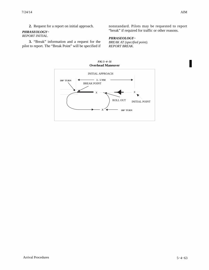
AIM4/3/14
5−4−63Arrival Procedures
2. Request for a report on initial approach.
PHRASEOLOGY−REPORT INITIAL.
3. “Break” information and a request for thepilot to report. The “Break Point” will be specified if
nonstandard. Pilots may be requested to report“break” if required for traffic or other reasons.
PHRASEOLOGY−BREAK AT (specified point).REPORT BREAK.
FIG 5−4−31
Overhead Maneuver
3 - 5 NM
X X
INITIAL POINT
INITIAL APPROACH
X
ROLL OUT
BREAK POINT
180° TURN
180° TURN
7/24/14 AIM

AIM4/3/14
5−6−1National Security and Interception Procedures
Section 6. National Security and Interception Procedures
5−6−1. National Security
a. National security in the control of air traffic isgoverned by 14 CFR Part 99.
b. All aircraft entering domestic U.S. airspacefrom points outside must provide for identificationprior to entry. To facilitate early aircraft identificationof all aircraft in the vicinity of U.S. and internationalairspace boundaries, Air Defense IdentificationZones (ADIZ) have been established.
REFERENCE−AIM, ADIZ Boundaries and Designated Mountainous Areas, Paragraph 5−6−5.
c. Operational requirements for aircraft oper-ations associated with an ADIZ are as follows:
1. Flight Plan. Except as specified in subpara-graphs d and e below, an IFR or DVFR flight planmust be filed with an appropriate aeronautical facilityas follows:
(a) Generally, for all operations that enter anADIZ.
(b) For operations that will enter or exit theU.S. and which will operate into, within or across theContiguous U.S. ADIZ regardless of true airspeed.
(c) The flight plan must be filed beforedeparture except for operations associated with theAlaskan ADIZ when the airport of departure has nofacility for filing a flight plan, in which case the flightplan may be filed immediately after takeoff or whenwithin range of the aeronautical facility.
2. Two-way Radio. For the majority of opera-tions associated with an ADIZ, an operating two-wayradio is required. See 14 CFR Section 99.1 forexceptions.
3. Transponder Requirements. Unless other-wise authorized by ATC, each aircraft conductingoperations into, within, or across the Contiguous U.S.ADIZ must be equipped with an operable radarbeacon transponder having altitude reporting capa-bility (Mode C), and that transponder must be turnedon and set to reply on the appropriate code or asassigned by ATC.
4. Position Reporting.
(a) For IFR flight. Normal IFR positionreporting.
(b) For DVFR flights:
(1) The pilot reports to an appropriateaeronautical facility before penetration: the time,position, and altitude at which the aircraft passed thelast reporting point before penetration and theestimated time of arrival over the next appropriatereporting point along the flight route;
(2) If there is no appropriate reporting pointalong the flight route, the pilot reports at least 15minutes before penetration: the estimated time,position, and altitude at which the pilot will penetrate;or
(3) If the departure airport is within anADIZ or so close to the ADIZ boundary that itprevents the pilot from complying with paragraphs(b)(1) or (2) of this section, the pilot must reportimmediately after departure: the time of departure,the altitude, and the estimated time of arrival over thefirst reporting point along the flight route.
(c) For inbound aircraft of foreign reg-istry. The pilot must report to the aeronauticalfacility at least one hour prior to ADIZ penetration.
5. Aircraft Position Tolerances.
(a) Over land, the tolerance is within plus orminus five minutes from the estimated time over areporting point or point of penetration and within10 NM from the centerline of an intended track overan estimated reporting point or penetration point.
(b) Over water, the tolerance is plus or minusfive minutes from the estimated time over a reportingpoint or point of penetration and within 20 NM fromthe centerline of the intended track over an estimatedreporting point or point of penetration (to include theAleutian Islands).
6. Land−Based ADIZ. Land−Based ADIZ areactivated and deactivated over U.S. metropolitanareas as needed, with dimensions, activation datesand other relevant information disseminated viaNOTAM.
(a) In addition to requirements outlined insubparagraphs c1 through c3, pilots operating within
7/24/14 AIM
AIM 4/3/14
5−6−2 National Security and Interception Procedures
a Land−Based ADIZ must report landing or leavingthe Land−Based ADIZ if flying too low for radarcoverage.
(b) Pilots unable to comply with all require-ments must remain clear of Land−Based ADIZ. Pilotsentering a Land−Based ADIZ without authorizationor who fail to follow all requirements riskinterception by military fighter aircraft.
d. Except when applicable under 14 CFRSection 99.7, 14 CFR Part 99 does not apply toaircraft operations:
1. Within the 48 contiguous states and theDistrict of Columbia, or within the State of Alaska,and remains within 10 miles of the point of departure;
2. Over any island, or within three nauticalmiles of the coastline of any island, in the HawaiiADIZ; or
3. Associated with any ADIZ other than theContiguous U.S. ADIZ, when the aircraft trueairspeed is less than 180 knots.
e. Authorizations to deviate from the requirementsof Part 99 may also be granted by the ARTCC, on alocal basis, for some operations associated with anADIZ.
f. An airfiled VFR Flight Plan makes an aircraftsubject to interception for positive identificationwhen entering an ADIZ. Pilots are, therefore, urgedto file the required DVFR flight plan either in personor by telephone prior to departure.
g. Special Security Instructions.
1. Each person operating an aircraft in an ADIZor Defense Area must, in addition to the applicablerules of part 99, comply with special securityinstructions issued by the Administrator in theinterest of national security, pursuant to agreementbetween the FAA and the Department of Defense, orbetween the FAA and a U.S. Federal security orintelligence agency.
2. Defense Area means any airspace of thecontiguous United States that is not an ADIZ in whichthe control of aircraft is required for reasons ofnational security.
h. Emergency Security Control of Air Traffic(ESCAT).
1. During defense emergency or air defenseemergency conditions, additional special securityinstructions may be issued in accordance with32 CFR 245 Plan for the Emergency Security Controlof Air Traffic (ESCAT).
2. Under the provisions of 32 CFR 245, themilitary will direct the action to be taken in regardto landing, grounding, diversion, or dispersal ofaircraft and the control of air navigation aids in thedefense of the U.S. during emergency conditions.
3. At the time a portion or all of ESCAT isimplemented, ATC facilities will broadcastappropriate instructions received from the Air TrafficControl System Command Center (ATCSCC) overavailable ATC frequencies. Depending oninstructions received from the ATCSCC, VFR flightsmay be directed to land at the nearest availableairport, and IFR flights will be expected to proceed asdirected by ATC.
4. Pilots on the ground may be required to file aflight plan and obtain an approval (through FAA)prior to conducting flight operation.
5. In view of the above, all pilots should monitoran ATC or FSS frequency at all times whileconducting flight operations.
5−6−2. Interception Procedures
a. General.
1. In conjunction with the FAA, Air DefenseSectors monitor air traffic and could order anintercept in the interest of national security ordefense. Intercepts during peacetime operations arevastly different than those conducted under increasedstates of readiness. The interceptors may be fightersor rotary wing aircraft. The reasons for aircraftintercept include, but are not limited to:
(a) Identify an aircraft;
(b) Track an aircraft;
(c) Inspect an aircraft;
(d) Divert an aircraft;
(e) Establish communications with an air-craft.
2. When specific information is required (i.e.,markings, serial numbers, etc.) the interceptor
3/15/077110.65R CHG 2AIM 7/24/14
AIM4/3/14
5−6−3National Security and Interception Procedures
pilot(s) will respond only if, in their judgment, therequest can be conducted in a safe manner. Interceptprocedures are described in some detail in theparagraphs below. In all situations, the interceptorpilot will consider safety of flight for all concernedthroughout the intercept procedure. The interceptorpilot(s) will use caution to avoid startling theintercepted crew or passengers and understand thatmaneuvers considered normal for interceptor aircraftmay be considered hazardous to other aircraft.
3. All aircraft operating in US national airspaceare highly encouraged to maintain a listening watchon VHF/UHF guard frequencies (121.5 or 243.0MHz). If subjected to a military intercept, it isincumbent on civilian aviators to understand theirresponsibilities and to comply with ICAO standardsignals relayed from the intercepting aircraft.Specifically, aviators are expected to contact airtraffic control without delay (if able) on the localoperating frequency or on VHF/UHF guard.Noncompliance may result in the use of force.
b. Fighter intercept phases (See FIG 5−6−1).
1. Approach Phase.As standard procedure, intercepted aircraft areapproached from behind. Typically, interceptoraircraft will be employed in pairs, however, it is notuncommon for a single aircraft to perform theintercept operation. Safe separation between inter-ceptors and intercepted aircraft is the responsibility ofthe intercepting aircraft and will be maintained at alltimes.
2. Identification Phase.Interceptor aircraft will initiate a controlled closuretoward the aircraft of interest, holding at a distance nocloser than deemed necessary to establish positiveidentification and to gather the necessary informa-tion. The interceptor may also fly past the intercepted
aircraft while gathering data at a distance consideredsafe based on aircraft performance characteristics.
3. Post Intercept Phase.An interceptor may attempt to establish communica-tions via standard ICAO signals. In time-criticalsituations where the interceptor is seeking animmediate response from the intercepted aircraft or ifthe intercepted aircraft remains non-compliant toinstruction, the interceptor pilot may initiate a divertmaneuver. In this maneuver, the interceptor fliesacross the intercepted aircraft’s flight path (minimum500 feet separation and commencing from slightlybelow the intercepted aircraft altitude) in the generaldirection the intercepted aircraft is expected to turn.The interceptor will rock its wings (daytime) or flashexternal lights/select afterburners (night) whilecrossing the intercepted aircraft’s flight path. Theinterceptor will roll out in the direction theintercepted aircraft is expected to turn beforereturning to verify the aircraft of interest iscomplying. The intercepted aircraft is expected toexecute an immediate turn to the direction of theintercepting aircraft. If the aircraft of interest does notcomply, the interceptor may conduct a secondclimbing turn across the intercepted aircraft’s flightpath (minimum 500 feet separation and commencingfrom slightly below the intercepted aircraft altitude)while expending flares as a warning signal to theintercepted aircraft to comply immediately and toturn in the direction indicated and to leave the area.The interceptor is responsible to maintain safeseparation during these and all intercept maneuvers.Flight safety is paramount.
NOTE−1. NORAD interceptors will take every precaution topreclude the possibility of the intercepted aircraftexperiencing jet wash/wake turbulence; however, there isa potential that this condition could be encountered.
2. During Night/IMC, the intercept will be from belowflight path.
7/24/14 AIM
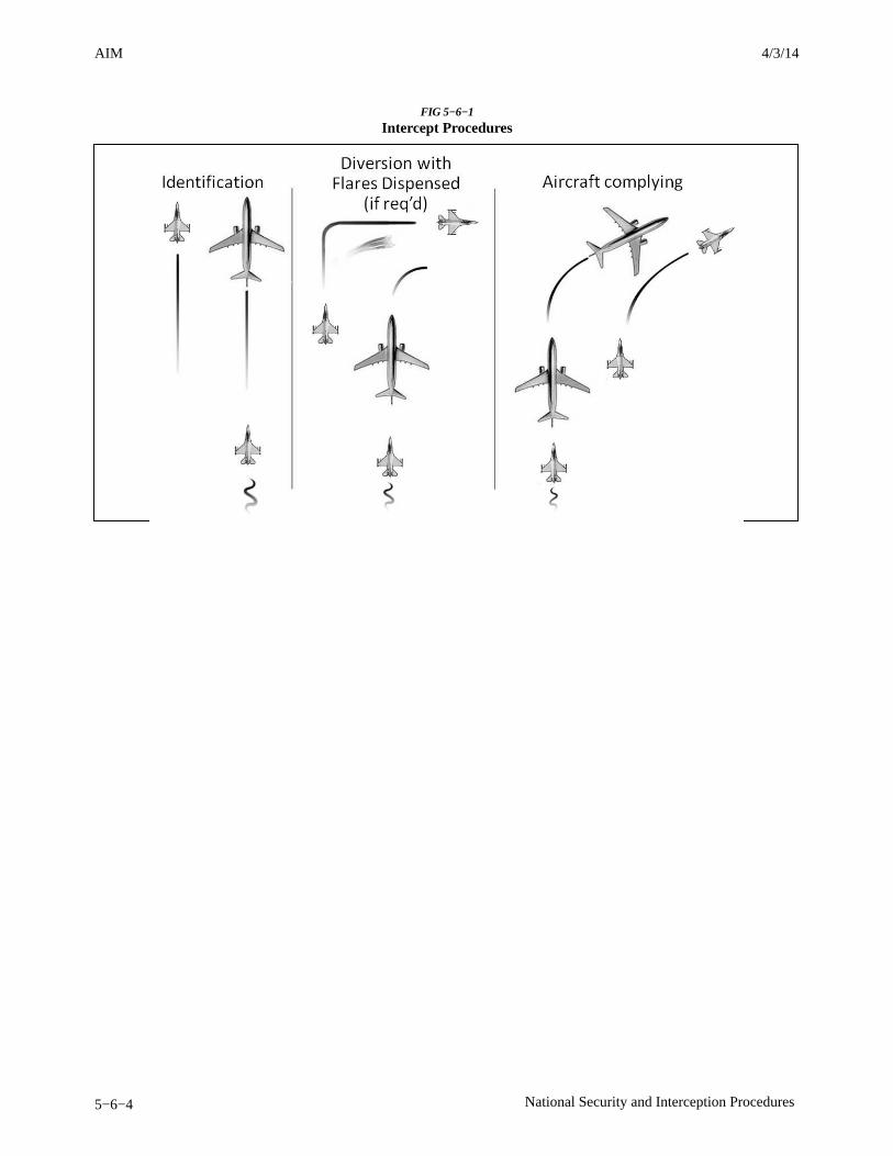
AIM 4/3/14
5−6−4 National Security and Interception Procedures
FIG 5−6−1
Intercept Procedures
AIM4/3/14
7−1−3Meteorology
c. Other Sources of Weather Information
1. Telephone Information Briefing Service(TIBS) (FSS); and in Alaska, Transcribed WeatherBroadcast (TWEB) locations, and telephone accessto the TWEB (TEL−TWEB) provide continuouslyupdated recorded weather information for short orlocal flights. Separate paragraphs in this section giveadditional information regarding these services.
REFERENCE−AIM, Telephone Information Briefing Service (TIBS), Paragraph 7−1−8.AIM, Transcribed Weather Broadcast (TWEB) (Alaska Only),Paragraph 7−1−9.
2. Weather and aeronautical information arealso available from numerous private industrysources on an individual or contract pay basis.Information on how to obtain this service should beavailable from local pilot organizations.
3. The Direct User Access Terminal Sys-tem (DUATS) can be accessed by pilots with acurrent medical certificate toll-free in the 48 contigu-ous States via personal computer. Pilots can receivealpha-numeric preflight weather data and filedomestic VFR and IFR flight plans. The followingare the contract DUATS vendors:
Computer Sciences Corporation (CSC) 15000 Conference Center DriveChantilly, VA 22021−3808Internet Access: http://www.duats.comTelnet Access (modem terminal−style): (800) 767−9989 or telnet://direct.duats.comFor customer service: (800) 345−3828
Data Transformation Corporation (DTC)108−D Greentree RoadTurnersville, NJ 08012Internet Access: http://www.duat.comFor customer service: (800)243−3828
d. Inflight weather information is available fromany FSS within radio range. The common frequencyfor all FSSs is 122.2. Discrete frequencies forindividual stations are listed in the A/FD.
1. Information on In-Flight Weather broadcasts.
REFERENCE−AIM, Inflight Weather Broadcasts, Paragraph 7−1−10.
2. En Route Flight Advisory Service (EFAS) isprovided to serve the nonroutine weather needs ofpilots in flight.
REFERENCE−AIM, En Route Flight Advisory Service (EFAS), Paragraph 7−1−5, givesdetails on this service.
7−1−3. Use of Aviation Weather Products
a. Air carriers and operators certificated under theprovisions of 14 CFR Part 119 are required to use theaeronautical weather information systems defined inthe Operations Specifications issued to that certifi-cate holder by the FAA. These systems may utilizebasic FAA/National Weather Service (NWS) weatherservices, contractor− or operator−proprietary weath-er services and/or Enhanced Weather InformationSystem (EWINS) when approved in the OperationsSpecifications. As an integral part of this systemapproval, the procedures for collecting, producingand disseminating aeronautical weather information,as well as the crew member and dispatcher training tosupport the use of system weather products, must beaccepted or approved.
b. Operators not certificated under the provisionsof 14 CFR Part 119 are encouraged to use FAA/NWSproducts through Flight Service Stations, Direct UserAccess Terminal System (DUATS), and/or FlightInformation Services−Broadcast (FIS−B).
c. The suite of available aviation weather producttypes is expanding, with the development of newsensor systems, algorithms and forecast models. TheFAA and NWS, supported by various weatherresearch laboratories and corporations under contractto the Government, develop and implement newaviation weather product types. The FAA’s NextGenAviation Weather Research Program (AWRP)facilitates collaboration between the NWS, the FAA,and various industry and research representatives.This collaboration ensures that user needs andtechnical readiness requirements are met beforeexperimental products mature to operational applica-tion.
d. The AWRP manages the transfer of aviationweather R&D to operational use through technicalreview panels and conducting safety assessments toensure that newly developed aviation weatherproducts meet regulatory requirements and enhancesafety.
e. The AWRP review and decision−makingprocess applies criteria to weather products at variousstages . The stages are composed of the following:
1. Sponsorship of user needs.
AIM 4/3/14
7−1−4 Meteorology
2. R & D and controlled testing.
3. Experimental application.
4. Operational application.
f. Pilots and operators should be aware thatweather services provided by entities other than FAA,NWS or their contractors (such as the DUAT/DUATSand Lockheed Martin Flight Services) may not meetFAA/NWS quality control standards. Hence,operators and pilots contemplating using suchservices should request and/or review an appropriatedescription of services and provider disclosure. Thisshould include, but is not limited to, the type ofweather product (e.g., current weather or forecastweather), the currency of the product (i.e., productissue and valid times), and the relevance of theproduct. Pilots and operators should be cautiouswhen using unfamiliar products, or products notsupported by FAA/NWS technical specifications.
NOTE−When in doubt, consult with a FAA Flight Service StationSpecialist.
g. In addition, pilots and operators should beaware there are weather services and productsavailable from government organizations beyond thescope of the AWRP process mentioned earlier in thissection. For example, governmental agencies such asthe NWS and the Aviation Weather Center (AWC), orresearch organizations such as the National Centerfor Atmospheric Research (NCAR) display weather“model data” and “experimental” products whichrequire training and/or expertise to properly interpretand use. These products are developmental proto-types that are subject to ongoing research and canchange without notice. Therefore, some data ondisplay by government organizations, or governmentdata on display by independent organizations may beunsuitable for flight planning purposes. Operatorsand pilots contemplating using such services shouldrequest and/or review an appropriate description ofservices and provider disclosure. This should include,but is not limited to, the type of weather product (forexample, current weather or forecast weather), thecurrency of the product (i.e., product issue and validtimes), and the relevance of the product. Pilots andoperators should be cautious when using unfamiliarweather products.
NOTE−When in doubt, consult with a FAA Flight Service StationSpecialist.
h. With increased access to weather products viathe public Internet, the aviation community hasaccess to an over whelming amount of weatherinformation and data that support self-briefing. FAAAC 00-45 (current edition) describes the weatherproducts distributed by the NWS. Pilots andoperators using the public Internet to access weatherfrom a third party vendor should request and/orreview an appropriate description of services andprovider disclosure. This should include, but is notlimited to, the type of weather product (for example,current weather or forecast weather), the currency ofthe product (i.e., product issue and valid times), andthe relevance of the product. Pilots and operatorsshould be cautious when using unfamiliar weatherproducts and when in doubt, consult with a FlightService Specialist.
i. The development of new weather products,coupled with the termination of some legacy textualand graphical products may create confusion betweenregulatory requirements and the new products. Allflight−related, aviation weather decisions must bebased on all available pertinent weather products. Asevery flight is unique and the weather conditions forthat flight vary hour by hour, day to day, multipleweather products may be necessary to meet aviationweather regulatory requirements. Many new weatherproducts now have a Precautionary Use Statementthat details the proper use or application of thespecific product.
j. The FAA has identified three distinct types ofweather information available to pilots and operators.
1. Observations. Raw weather data collectedby some type of sensor suite including surface andairborne observations, radar, lightning, satelliteimagery, and profilers.
2. Analysis. Enhanced depiction and/or inter-pretation of observed weather data.
3. Forecasts. Predictions of the developmentand/or movement of weather phenomena based onmeteorological observations and various mathemat-ical models.
k. Not all sources of aviation weather informationare able to provide all three types of weatherinformation. The FAA has determined that operatorsand pilots may utilize the following approved sourcesof aviation weather information:
1. Federal Government. The FAA and NWScollect raw weather data, analyze the observations,
3/15/077110.65R CHG 2AIM 7/24/14
AIM4/3/14
7−1−5Meteorology
and produce forecasts. The FAA and NWSdisseminate meteorological observations, analyses,and forecasts through a variety of systems. Inaddition, the Federal Government is the onlyapproval authority for sources of weather observa-tions; for example, contract towers and airportoperators may be approved by the Federal
Government to provide weather observations.
2. Enhanced Weather Information System(EWINS). An EWINS is an FAA authorized,proprietary system for tracking, evaluating, report-ing, and forecasting the presence or lack of adverseweather phenomena. The FAA authorizes a certific-ate holder to use an EWINS to produce flightmovement forecasts, adverse weather phenomenaforecasts, and other meteorological advisories. Formore detailed information regarding EWINS, see theAviation Weather Services Advisory Circular 00−45and the Flight Standards Information ManagementSystem 8900.1.
3. Commercial Weather InformationProviders. In general, commercial providersproduce proprietary weather products based onNWS/FAA products with formatting and layoutmodifications but no material changes to the weatherinformation itself. This is also referred to as“repackaging.” In addition, commercial providersmay produce analyses, forecasts, and otherproprietary weather products that substantially alterthe information contained in government−producedproducts. However, those proprietary weatherproducts that substantially alter government−produced weather products or information, may onlybe approved for use by 14 CFR Part 121 and Part 135certificate holders if the commercial provider isEWINS qualified.
NOTE−Commercial weather information providers contracted byFAA to provide weather observations, analyses, andforecasts (e.g., contract towers) are included in the FederalGovernment category of approved sources by virtue ofmaintaining required technical and quality assurancestandards under Federal Government oversight.
l. As a point of clarification, AdvisoryCircular 00−62, Internet Communications ofAviation Weather and NOTAMS, describes theprocess for a weather information provider to becomea Qualified Internet Communications Provider(QICP) and only applies to 14 CFR Part 121 and
Part 135 certificate holders. Therefore, pilotsconducting operations under 14 CFR Part 91 mayaccess weather products via the public Internet.
7−1−4. Preflight Briefing
a. Flight Service Stations (FSSs) are the primarysource for obtaining preflight briefings and inflightweather information. Flight Service Specialists arequalified and certificated by the NWS as PilotWeather Briefers. They are not authorized to makeoriginal forecasts, but are authorized to translate andinterpret available forecasts and reports directly intoterms describing the weather conditions which youcan expect along your flight route and at yourdestination. Available aviation weather reports,forecasts and aviation weather charts are displayed ateach FSS, for pilot use. Pilots should feel free to usethese self briefing displays where available, or to askfor a briefing or assistance from the specialist on duty.Three basic types of preflight briefings are availableto serve your specific needs. These are: StandardBriefing, Abbreviated Briefing, and Outlook Brief-ing. You should specify to the briefer the type ofbriefing you want, along with your appropriatebackground information. This will enable the brieferto tailor the information to your intended flight. Thefollowing paragraphs describe the types of briefingsavailable and the information provided in eachbriefing.REFERENCE−AIM, Preflight Preparation, Paragraph 5−1−1, for items that arerequired.
b. Standard Briefing. You should request aStandard Briefing any time you are planning a flightand you have not received a previous briefing or havenot received preliminary information through massdissemination media; e.g., TIBS, TWEB (Alaskaonly), etc. International data may be inaccurate orincomplete. If you are planning a flight outside ofU.S. controlled airspace, the briefer will advise youto check data as soon as practical after enteringforeign airspace, unless you advise that you have theinternational cautionary advisory. The briefer willautomatically provide the following information inthe sequence listed, except as noted, when it isapplicable to your proposed flight.
1. Adverse Conditions. Significant meteoro-logical and/or aeronautical information that mightinfluence the pilot to alter or cancel the proposedflight; for example, hazardous weather conditions,
7/24/14 AIM
AIM 4/3/14
7−1−6 Meteorology
airport closures, air traffic delays, etc. Pilots shouldbe especially alert for current or forecast weatherthat could reduce flight minimums below VFR orIFR conditions. Pilots should also be alert for anyreported or forecast icing if the aircraft is not certifiedfor operating in icing conditions. Flying into areasof icing or weather below minimums could havedisastrous results.
2. VFR Flight Not Recommended. WhenVFR flight is proposed and sky conditions orvisibilities are present or forecast, surface or aloft,that, in the briefer’s judgment, would make flightunder VFR doubtful, the briefer will describe theconditions, describe the affected locations, and usethe phrase “VFR flight not recommended.” Thisrecommendation is advisory in nature. The finaldecision as to whether the flight can be conductedsafely rests solely with the pilot. Upon receiving a“VFR flight not recommended” statement, thenon−IFR rated pilot will need to make a “go or no go”decision. This decision should be based on weighingthe current and forecast weather conditions againstthe pilot’s experience and ratings. The aircraft’sequipment, capabilities and limitations should alsobe considered.
NOTE−Pilots flying into areas of minimal VFR weather couldencounter unforecasted lowering conditions that place theaircraft outside the pilot’s ratings and experience level.This could result in spatial disorientation and/or loss ofcontrol of the aircraft.
3. Synopsis. A brief statement describing thetype, location and movement of weather systemsand/or air masses which might affect the proposedflight.
NOTE−These first 3 elements of a briefing may be combined in anyorder when the briefer believes it will help to more clearlydescribe conditions.
4. Current Conditions. Reported weatherconditions applicable to the flight will be summarizedfrom all available sources; e.g., METARs/ SPECIs,PIREPs, RAREPs. This element will be omitted if theproposed time of departure is beyond 2 hours, unlessthe information is specifically requested by the pilot.
5. En Route Forecast. Forecast en routeconditions for the proposed route are summarized inlogical order; i.e., departure/climbout, en route, anddescent. (Heights are MSL, unless the contractions
“AGL” or “CIG” are denoted indicating that heightsare above ground.)
6. Destination Forecast. The destination fore-cast for the planned ETA. Any significant changeswithin 1 hour before and after the planned arrival areincluded.
7. Winds Aloft. Forecast winds aloft will beprovided using degrees of the compass. The brieferwill interpolate wind directions and speeds betweenlevels and stations as necessary to provide expectedconditions at planned altitudes. (Heights are MSL.)Temperature information will be provided on request.
8. Notices to Airmen (NOTAMs).
(a) Available NOTAM (D) information perti-nent to the proposed flight, including special useairspace (SUA) NOTAMs for restricted areas, aerialrefueling, and night vision goggles (NVG).
NOTE−Other SUA NOTAMs (D), such as military operationsarea (MOA), military training route (MTR), and warningarea NOTAMs, are considered “upon request” briefingitems as indicated in paragraph 7−1−4b10(a).
(b) Prohibited Areas P−40, P−49, P−56,and the special flight rules area (SFRA) forWashington, DC.
(c) FSS briefers do not provide FDC NOTAMinformation for special instrument approach proce-dures unless specifically asked. Pilots authorized bythe FAA to use special instrument approachprocedures must specifically request FDC NOTAMinformation for these procedures.
NOTE−NOTAM information may be combined with currentconditions when the briefer believes it is logical to do so.
NOTE−NOTAM (D) information and FDC NOTAMs which havebeen published in the Notices to Airmen Publication arenot included in pilot briefings unless a review of thispublication is specifically requested by the pilot. Forcomplete flight information you are urged to review theprinted NOTAMs in the Notices to Airmen Publication andthe A/FD in addition to obtaining a briefing.
9. ATC Delays. Any known ATC delays andflow control advisories which might affect theproposed flight.
10. Pilots may obtain the following fromflight service station briefers upon request:
(a) Information on SUA and SUA−relatedairspace, except those listed in paragraph 7−1−4b8.

AIM4/3/14
7−1−23Meteorology
of information that may provide this specificguidance include manufacturer’s manuals, trainingprograms, and reference guides.
(b) FIS should not serve as the sole source ofaviation weather and other operational information.ATC, FSSs, and, if applicable, AOCC VHF/HF voiceremain as a redundant method of communicatingaviation weather, NOTAMs, and other operationalinformation to aircraft in flight. FIS augments thesetraditional ATC/FSS/AOCC services and, for someproducts, offers the advantage of being displayed asgraphical information. By using FIS for orientation,the usefulness of information received fromconventional means may be enhanced. For example,FIS may alert the pilot to specific areas of concernthat will more accurately focus requests made to FSSor AOCC for inflight updates or similar queries madeto ATC.
(c) The airspace and aeronautical environ-ment is constantly changing. These changes occurquickly and without warning. Critical operationaldecisions should be based on use of the most currentand appropriate data available. When differencesexist between FIS and information obtained by voicecommunication with ATC, FSS, and/or AOCC (ifapplicable), pilots are cautioned to use the mostrecent data from the most authoritative source.
(d) FIS aviation weather products (forexample, graphical ground−based radar precipitationdepictions) are not appropriate for tactical (typicaltimeframe of less than 3 minutes) avoidance of severeweather such as negotiating a path through a weatherhazard area. FIS supports strategic (typical timeframeof 20 minutes or more) weather decisionmaking suchas route selection to avoid a weather hazard area in itsentirety. The misuse of information beyond itsapplicability may place the pilot and aircraft injeopardy. In addition, FIS should never be used in lieuof an individual preflight weather and flight planningbriefing.
(e) DLSP offer numerous MET and AIproducts with information that can be layered on topof each other. Pilots need to be aware that too muchinformation can have a negative effect on theircognitive work load. Pilots need to manage theamount of information to a level that offers the mostpertinent information to that specific flight withoutcreating a cockpit distraction. Pilots may need to
adjust the amount of information based on numerousfactors including, but not limited to, the phase offlight, single pilot operation, autopilot availability,class of airspace, and the weather conditionsencountered.
(f) FIS NOTAM products, including Tempor-ary Flight Restriction (TFR) information, areadvisory−use information and are intended forsituational awareness purposes only. Cockpit dis-plays of this information are not appropriate fortactical navigation − pilots should stay clear of anygeographic area displayed as a TFR NOTAM. Pilotsshould contact FSSs and/or ATC while en route toobtain updated information and to verify the cockpitdisplay of NOTAM information.
(g) FIS supports better pilot decisionmakingby increasing situational awareness. Better decision−making is based on using information from a varietyof sources. In addition to FIS, pilots should takeadvantage of other weather/NAS status sources,including, briefings from Flight Service Stations,FAA’s en route “Flight Watch” service, data fromother air traffic control facilities, airline operationcontrol centers, pilot reports, as well as their ownobservations.
(h) FAA’s Flight Information Service−Broadcast (FIS−B).
(1) FIS−B is a ground−based broadcastservice provided through the FAA’s AutomaticDependent Surveillance–Broadcast (ADS−B) Ser-vices Universal Access Transceiver (UAT) network.The service provides users with a 978 MHz data linkcapability when operating within range and line−of−sight of a transmitting ground station. FIS−B enablesusers of properly−equipped aircraft to receive anddisplay a suite of broadcast weather and aeronauticalinformation products.
(2) The following list represents the initialsuite of text and graphical products available throughFIS−B and provided free−of−charge. Detailedinformation concerning FIS−B meteorologicalproducts can be found in Advisory Circular 00−45,Aviation Weather Services, and AC 00-63, Use ofCockpit Displays of Digital Weather and Aeronautic-al Information. Information on Special Use Airspace(SUA), Temporary Flight Restriction (TFR), andNotice to Airmen (NOTAM) products can be foundin Chapters 3, 4 and 5 of this manual.
AIM 4/3/14
7−1−24 Meteorology
[a] Text: Aviation Routine WeatherReport (METAR) and Special Aviation Report(SPECI);
[b] Text: Pilot Weather Report (PIREP);
[c] Text: Winds and Temperatures Aloft;
[d] Text: Terminal Aerodrome Forecast(TAF) and amendments;
[e] Text: Notice to Airmen (NOTAM)Distant and Flight Data Center;
[f] Text/Graphic: Airmen’s Meteorolo-gical Conditions (AIRMET);
[g] Text/Graphic: Significant Meteoro-logical Conditions (SIGMET);
[h] Text/Graphic: Convective SIG-MET;
[i] Text/Graphic: Special Use Airspace(SUA);
[j] Text/Graphic: Temporary FlightRestriction (TFR) NOTAM; and
[k] Graphic: NEXRAD Composite Re-flectivity Products (Regional and National).
(3) Users of FIS−B should familiarizethemselves with the operational characteristics andlimitations of the system, including: system architec-ture; service environment; product lifecycles; modesof operation; and indications of system failure.
(4) FIS−B products are updated andtransmitted at specific intervals based primarily onproduct issuance criteria. Update intervals aredefined as the rate at which the product data isavailable from the source for transmission. Transmis-sion intervals are defined as the amount of time withinwhich a new or updated product transmission must becompleted and/or the rate or repetition interval atwhich the product is rebroadcast. Update andtransmission intervals for each product are providedin TBL 7−1−1.
(5) Where applicable, FIS−B productsinclude a look−ahead range expressed in nauticalmiles (NM) for three service domains: AirportSurface; Terminal Airspace; and Enroute/Gulf−of−Mexico (GOMEX). TBL 7−1−2 provides servicedomain availability and look−ahead ranging for eachFIS−B product.
(6) Prior to using this capability, usersshould familiarize themselves with the operation ofFIS−B avionics by referencing the applicable User’sGuides. Guidance concerning the interpretation ofinformation displayed should be obtained from theappropriate avionics manufacturer.
(7) FIS−B malfunctions not attributed toaircraft system failures or covered by active NOTAMshould be reported by radio or telephone to the nearestFSS facility.
b. Non−FAA FIS Systems. Several commercialvendors also provide customers with FIS data overboth the aeronautical spectrum and on otherfrequencies using a variety of data link protocols. Insome cases, the vendors provide only the commu-nications system that carries customer messages,such as the Aircraft Communications Addressing andReporting System (ACARS) used by many air carrierand other operators.
1. Operators using non−FAA FIS data forinflight weather and other operational informationshould ensure that the products used conform toFAA/NWS standards. Specifically, aviation weatherand NAS status information should meet thefollowing criteria:
(a) The products should be either FAA/NWS“accepted” aviation weather reports or products, orbased on FAA/NWS accepted aviation weatherreports or products. If products are used which do notmeet this criteria, they should be so identified. Theoperator must determine the applicability of suchproducts to their particular flight operations.
(b) In the case of a weather product which isthe result of the application of a process which altersthe form, function or content of the base FAA/NWSaccepted weather product(s), that process, and anylimitations to the application of the resultant product,should be described in the vendor’s user guidancematerial.
2. An example would be a NEXRAD radarcomposite/mosaic map, which has been modified bychanging the scaling resolution. The methodology ofassigning reflectivity values to the resultant imagecomponents should be described in the vendor’sguidance material to ensure that the user canaccurately interpret the displayed data.
3/15/077110.65R CHG 2AIM 7/24/14
AIM4/3/14
7−1−25Meteorology
TBL 7−1−1
FIS−B Over UAT Product Update and Transmission Intervals
Product FIS-B Over UAT Service
Update Intervals1FIS-B Service
Transmission
Intervals2
AIRMET As Available 5 minutes
Convective SIGMET As Available 5 minutes
METARs/SPECIs 1 minute/As Available 5 minutes
NEXRAD Composite Reflectivity (CONUS) 15 minutes 15 minutes
NEXRAD Composite Reflectivity (Regional) 5 minutes 2.5 minutes
NOTAMs-D/FDC/TFR As Available 10 minutes
PIREP As Available 10 minutes
SIGMET As Available 5 minutes
SUA Status As Available 10 minutes
TAF/AMEND 8 Hours/As Available 10 minutes
Temperatures Aloft 12 Hours 10 minutes
Winds Aloft 12 Hours 10 minutes
1 The Update Interval is the rate at which the product data is available from the source.
2 The Transmission Interval is the amount of time within which a new or updated product transmission must be completedand the rate or repetition interval at which the product is rebroadcast.
7/24/14 AIM
AIM 4/3/14
7−1−26 Meteorology
TBL 7−1−2
Product Parameters for Low/Medium/High Altitude Tier Radios
Product Surface Radios Low Altitude Tier Medium AltitudeTier
High Altitude Tier
CONUS NEXRAD N/A CONUS NEXRADnot provided
CONUS NEXRADimagery
CONUS NEXRADimagery
Winds & TempsAloft
500 NM look−aheadrange
500 NM look−aheadrange
750 NM look−aheadrange
1,000 NM look−ahead range
METAR 100 NM look−aheadrange
250 NM look−aheadrange
375 NM look−aheadrange
CONUS: CONUSClass B & C airportMETARs and 500NM look−aheadrange
Outside of CONUS:500 NM look-aheadrange
TAF 100 NM look−aheadrange
250 NM look−aheadrange
375 NM look−aheadrange
CONUS: CONUSClass B & C airportTAFs and 500 NMlook−ahead range
Outside of CONUS:500 NM look-aheadrange
AIRMET, SIGMET,PIREP, and SUA/SAA
100 NM look−aheadrange. PIREP/SUA/SAA is N/A.
250 NM look−aheadrange
375 NM look−aheadrange
500 NM look−aheadrange
Regional NEXRAD 150 NM look−aheadrange
150 NM look−aheadrange
200 NM look−aheadrange
250 NM look−aheadrange
NOTAMs D, FDC,and TFR
100 NM look−aheadrange
100 NM look−aheadrange
100 NM look−aheadrange
100 NM look−aheadrange
7−1−12. Weather Observing Programs
a. Manual Observations. With only a fewexceptions, these reports are from airport locationsstaffed by FAA or NWS personnel who manuallyobserve, perform calculations, and enter theseobservations into the (WMSCR) communicationsystem. The format and coding of these observationsare contained in Paragraph 7−1−30 , Key to AviationRoutine Weather Report (METAR) and AerodromeForecasts (TAF).
b. Automated Weather Observing System(AWOS).
1. Automated weather reporting systems areincreasingly being installed at airports. Thesesystems consist of various sensors, a processor, acomputer-generated voice subsystem, and a transmit-
ter to broadcast local, minute-by-minute weather datadirectly to the pilot.
NOTE−When the barometric pressure exceeds 31.00 inches Hg.,see Paragraph 7−2−2, Procedures, for the altimetersetting procedures.
2. The AWOS observations will include theprefix “AUTO” to indicate that the data are derivedfrom an automated system. Some AWOS locationswill be augmented by certified observers who willprovide weather and obstruction to vision informa-tion in the remarks of the report when the reportedvisibility is less than 7 miles. These sites, along withthe hours of augmentation, are to be published in theA/FD. Augmentation is identified in the observationas “OBSERVER WEATHER.” The AWOS windspeed, direction and gusts, temperature, dew point,
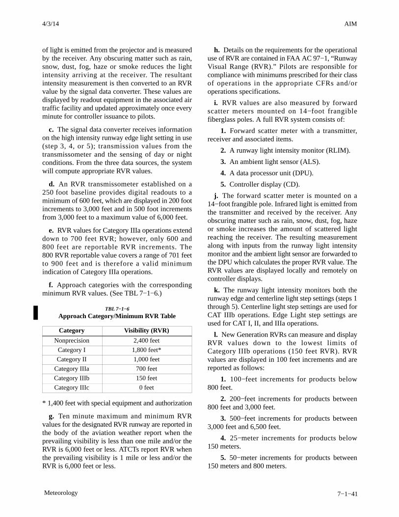
AIM4/3/14
7−1−41Meteorology
of light is emitted from the projector and is measuredby the receiver. Any obscuring matter such as rain,snow, dust, fog, haze or smoke reduces the lightintensity arriving at the receiver. The resultantintensity measurement is then converted to an RVRvalue by the signal data converter. These values aredisplayed by readout equipment in the associated airtraffic facility and updated approximately once everyminute for controller issuance to pilots.
c. The signal data converter receives informationon the high intensity runway edge light setting in use(step 3, 4, or 5); transmission values from thetransmissometer and the sensing of day or nightconditions. From the three data sources, the systemwill compute appropriate RVR values.
d. An RVR transmissometer established on a250 foot baseline provides digital readouts to aminimum of 600 feet, which are displayed in 200 footincrements to 3,000 feet and in 500 foot incrementsfrom 3,000 feet to a maximum value of 6,000 feet.
e. RVR values for Category IIIa operations extenddown to 700 feet RVR; however, only 600 and800 feet are reportable RVR increments. The800 RVR reportable value covers a range of 701 feetto 900 feet and is therefore a valid minimumindication of Category IIIa operations.
f. Approach categories with the correspondingminimum RVR values. (See TBL 7−1−6.)
TBL 7−1−6
Approach Category/Minimum RVR Table
Category Visibility (RVR)
Nonprecision 2,400 feet
Category I 1,800 feet*
Category II 1,000 feet
Category IIIa 700 feet
Category IIIb 150 feet
Category IIIc 0 feet
* 1,400 feet with special equipment and authorization
g. Ten minute maximum and minimum RVRvalues for the designated RVR runway are reported inthe body of the aviation weather report when theprevailing visibility is less than one mile and/or theRVR is 6,000 feet or less. ATCTs report RVR whenthe prevailing visibility is 1 mile or less and/or theRVR is 6,000 feet or less.
h. Details on the requirements for the operationaluse of RVR are contained in FAA AC 97−1, “RunwayVisual Range (RVR).” Pilots are responsible forcompliance with minimums prescribed for their classof operations in the appropriate CFRs and/oroperations specifications.
i. RVR values are also measured by forwardscatter meters mounted on 14−foot frangiblefiberglass poles. A full RVR system consists of:
1. Forward scatter meter with a transmitter,receiver and associated items.
2. A runway light intensity monitor (RLIM).
3. An ambient light sensor (ALS).
4. A data processor unit (DPU).
5. Controller display (CD).
j. The forward scatter meter is mounted on a14−foot frangible pole. Infrared light is emitted fromthe transmitter and received by the receiver. Anyobscuring matter such as rain, snow, dust, fog, hazeor smoke increases the amount of scattered lightreaching the receiver. The resulting measurementalong with inputs from the runway light intensitymonitor and the ambient light sensor are forwarded tothe DPU which calculates the proper RVR value. TheRVR values are displayed locally and remotely oncontroller displays.
k. The runway light intensity monitors both therunway edge and centerline light step settings (steps 1through 5). Centerline light step settings are used forCAT IIIb operations. Edge Light step settings areused for CAT I, II, and IIIa operations.
l. New Generation RVRs can measure and displayRVR values down to the lowest limits ofCategory IIIb operations (150 feet RVR). RVRvalues are displayed in 100 feet increments and arereported as follows:
1. 100−feet increments for products below800 feet.
2. 200−feet increments for products between800 feet and 3,000 feet.
3. 500−feet increments for products between3,000 feet and 6,500 feet.
4. 25−meter increments for products below150 meters.
5. 50−meter increments for products between150 meters and 800 meters.

AIM 4/3/14
7−1−42 Meteorology
6. 100−meter increments for products between800 meters and 1,200 meters.
7. 200−meter increments for products between1,200 meters and 2,000 meters.
7−1−16. Reporting of Cloud Heights
a. Ceiling, by definition in the CFRs and as usedin aviation weather reports and forecasts, is the heightabove ground (or water) level of the lowest layer ofclouds or obscuring phenomenon that is reported as“broken,” “overcast,” or “obscuration,” e.g., anaerodrome forecast (TAF) which reads “BKN030”refers to height above ground level. An area forecastwhich reads “BKN030” indicates that the height isabove mean sea level.REFERENCE−AIM, Key to Aerodrome Forecast (TAF) and Aviation Routine WeatherReport (METAR), Paragraph 7−1−30, defines “broken,” “overcast,” and“obscuration.”
b. Pilots usually report height values above MSL,since they determine heights by the altimeter. This istaken in account when disseminating and otherwiseapplying information received from pilots. (“Ceil-ing” heights are always above ground level.) Inreports disseminated as PIREPs, height referencesare given the same as received from pilots, that is,above MSL.
c. In area forecasts or inflight advisories, ceilingsare denoted by the contraction “CIG” when used withsky cover symbols as in “LWRG TO CIG OVC005,”or the contraction “AGL” after, the forecast cloudheight value. When the cloud base is given in heightabove MSL, it is so indicated by the contraction“MSL” or “ASL” following the height value. Theheights of clouds tops, freezing level, icing, andturbulence are always given in heights above ASL orMSL.
7−1−17. Reporting Prevailing Visibility
a. Surface (horizontal) visibility is reported inMETAR reports in terms of statute miles andincrements thereof; e.g., 1/16, 1/8, 3/
16, 1/4, 5/16, 3/
8, 1/2,
5/8, 3/4, 7/8, 1, 1 1/8, etc. (Visibility reported by an
unaugmented automated site is reported differentlythan in a manual report, i.e., ASOS/AWSS: 0, 1/16, 1/
8,1/4, 1/
2, 3/4, 1, 1 1/4, 1 1/2, 1 3/
4, 2, 2 1/2, 3, 4, 5, etc., AWOS:
M1/4, 1/4, 1/2, 3/4, 1, 1 1/4, 1 1/
2, 1 3/4, 2, 2 1/
2, 3, 4, 5, etc.)Visibility is determined through the ability to see andidentify preselected and prominent objects at a
known distance from the usual point of observation.Visibilities which are determined to be less than7 miles, identify the obscuring atmospheric condi-tion; e.g., fog, haze, smoke, etc., or combinationsthereof.
b. Prevailing visibility is the greatest visibilityequaled or exceeded throughout at least one half ofthe horizon circle, not necessarily contiguous.Segments of the horizon circle which may have asignificantly different visibility may be reported inthe remarks section of the weather report; i.e., thesoutheastern quadrant of the horizon circle may bedetermined to be 2 miles in mist while the remainingquadrants are determined to be 3 miles in mist.
c. When the prevailing visibility at the usual pointof observation, or at the tower level, is less than4 miles, certificated tower personnel will takevisibility observations in addition to those taken at theusual point of observation. The lower of these twovalues will be used as the prevailing visibility foraircraft operations.
7−1−18. Estimating Intensity of Rain andIce Pellets
a. Rain
1. Light. From scattered drops that, regardlessof duration, do not completely wet an exposed surfaceup to a condition where individual drops are easilyseen.
2. Moderate. Individual drops are not clearlyidentifiable; spray is observable just above pave-ments and other hard surfaces.
3. Heavy. Rain seemingly falls in sheets;individual drops are not identifiable; heavy spray toheight of several inches is observed over hardsurfaces.
b. Ice Pellets
1. Light. Scattered pellets that do not com-pletely cover an exposed surface regardless ofduration. Visibility is not affected.
2. Moderate. Slow accumulation on ground.Visibility reduced by ice pellets to less than 7 statutemiles.
3. Heavy. Rapid accumulation on ground.Visibility reduced by ice pellets to less than 3 statutemiles.
3/15/077110.65R CHG 2AIM 7/24/14

AIM4/3/14
7−1−43Meteorology
7−1−19. Estimating Intensity of Snow orDrizzle (Based on Visibility)
a. Light. Visibility more than 1/2 statute mile.
b. Moderate. Visibility from more than 1/4 stat-ute mile to 1/2 statute mile.
c. Heavy. Visibility 1/4 statute mile or less.
7−1−20. Pilot Weather Reports (PIREPs)
a. FAA air traffic facilities are required to solicitPIREPs when the following conditions are reportedor forecast: ceilings at or below 5,000 feet; visibilityat or below 5 miles (surface or aloft); thunderstormsand related phenomena; icing of light degree orgreater; turbulence of moderate degree or greater;wind shear and reported or forecast volcanic ashclouds.
b. Pilots are urged to cooperate and promptlyvolunteer reports of these conditions and otheratmospheric data such as: cloud bases, tops andlayers; flight visibility; precipitation; visibilityrestrictions such as haze, smoke and dust; wind ataltitude; and temperature aloft.
c. PIREPs should be given to the ground facilitywith which communications are established;i.e., EFAS, FSS, ARTCC, or terminal ATC. One ofthe primary duties of EFAS facilities, radio call“FLIGHT WATCH,” is to serve as a collection pointfor the exchange of PIREPs with en route aircraft.
d. If pilots are not able to make PIREPs by radio,reporting upon landing of the inflight conditionsencountered to the nearest FSS or Weather ForecastOffice will be helpful. Some of the uses made of thereports are:
1. The ATCT uses the reports to expedite theflow of air traffic in the vicinity of the field and forhazardous weather avoidance procedures.
2. The FSS uses the reports to brief other pilots,to provide inflight advisories, and weather avoidanceinformation to en route aircraft.
3. The ARTCC uses the reports to expedite theflow of en route traffic, to determine most favorablealtitudes, and to issue hazardous weather informationwithin the center’s area.
4. The NWS uses the reports to verify or amendconditions contained in aviation forecast andadvisories. In some cases, pilot reports of hazardousconditions are the triggering mechanism for theissuance of advisories. They also use the reports forpilot weather briefings.
5. The NWS, other government organizations,the military, and private industry groups use PIREPsfor research activities in the study of meteorologicalphenomena.
6. All air traffic facilities and the NWS forwardthe reports received from pilots into the weatherdistribution system to assure the information is madeavailable to all pilots and other interested parties.
e. The FAA, NWS, and other organizations thatenter PIREPs into the weather reporting system usethe format listed in TBL 7−1−7. Items 1 through 6 areincluded in all transmitted PIREPs along with one ormore of items 7 through 13. Although the PIREPshould be as complete and concise as possible, pilotsshould not be overly concerned with strict format orphraseology. The important thing is that theinformation is relayed so other pilots may benefitfrom your observation. If a portion of the report needsclarification, the ground station will request theinformation. Completed PIREPs will be transmittedto weather circuits as in the following examples:

AIM 4/3/14
7−1−44 Meteorology
TBL 7−1−7
PIREP Element Code Chart
PIREP ELEMENT PIREP CODE CONTENTS
1. 3−letter station identifier XXX Nearest weather reporting location to the reported phenomenon
2. Report type UA or UUA Routine or Urgent PIREP
3. Location /OV In relation to a VOR
4. Time /TM Coordinated Universal Time
5. Altitude /FL Essential for turbulence and icing reports
6. Type Aircraft /TP Essential for turbulence and icing reports
7. Sky cover /SK Cloud height and coverage (sky clear, few, scattered, broken, orovercast)
8. Weather /WX Flight visibility, precipitation, restrictions to visibility, etc.
9. Temperature /TA Degrees Celsius
10. Wind /WV Direction in degrees magnetic north and speed in knots
11. Turbulence /TB See AIM paragraph 7−1−23
12. Icing /IC See AIM paragraph 7−1−22
13. Remarks /RM For reporting elements not included or to clarify previouslyreported items
EXAMPLE−1. KCMH UA /OV APE 230010/TM 1516/FL085/TPBE20/SK BKN065/WX FV03SM HZ FU/TA 20/TB LGT
NOTE−1. One zero miles southwest of Appleton VOR; time1516 UTC; altitude eight thousand five hundred; aircrafttype BE200; bases of the broken cloud layer is six thousandfive hundred; flight visibility 3 miles with haze and smoke;air temperature 20 degrees Celsius; light turbulence.
EXAMPLE−2. KCRW UV /OV KBKW 360015−KCRW/TM1815/FL120//TP BE99/SK IMC/WX RA/TA M08 /WV290030/TB LGT−MDT/IC LGT RIME/RM MDT MXDICG DURC KROA NWBND FL080−100 1750Z
NOTE−2. From 15 miles north of Beckley VOR to Charles-ton VOR; time 1815 UTC; altitude 12,000 feet; typeaircraft, BE−99; in clouds; rain; temperature minus8 Celsius; wind 290 degrees magnetic at 30 knots; light tomoderate turbulence; light rime icing during climbnorthwestbound from Roanoke, VA, between 8,000 and10,000 feet at 1750 UTC.
7−1−21. PIREPs Relating to Airframe Icing
a. The effects of ice on aircraft are cumulative-thrust is reduced, drag increases, lift lessens, andweight increases. The results are an increase in stallspeed and a deterioration of aircraft performance. In
extreme cases, 2 to 3 inches of ice can form on theleading edge of the airfoil in less than 5 minutes. Ittakes but 1/2 inch of ice to reduce the lifting power ofsome aircraft by 50 percent and increases thefrictional drag by an equal percentage.
b. A pilot can expect icing when flying in visibleprecipitation, such as rain or cloud droplets, and thetemperature is between +02 and −10 degrees Celsius.When icing is detected, a pilot should do one of twothings, particularly if the aircraft is not equipped withdeicing equipment; get out of the area ofprecipitation; or go to an altitude where thetemperature is above freezing. This “warmer”altitude may not always be a lower altitude. Properpreflight action includes obtaining information on thefreezing level and the above freezing levels inprecipitation areas. Report icing to ATC, and ifoperating IFR, request new routing or altitude if icingwill be a hazard. Be sure to give the type of aircraft toATC when reporting icing. The following describeshow to report icing conditions.
1. Trace. Ice becomes perceptible. Rate ofaccumulation slightly greater than sublimation.Deicing/anti-icing equipment is not utilized unlessencountered for an extended period of time (over1 hour).
3/15/077110.65R CHG 2AIM 7/24/14
AIM4/3/14
7−1−59Meteorology
b. There is no useful correlation between theexternal visual appearance of thunderstorms and theseverity or amount of turbulence or hail within them.The visible thunderstorm cloud is only a portion of aturbulent system whose updrafts and downdraftsoften extend far beyond the visible storm cloud.Severe turbulence can be expected up to 20 milesfrom severe thunderstorms. This distance decreasesto about 10 miles in less severe storms.
c. Weather radar, airborne or ground based, willnormally reflect the areas of moderate to heavyprecipitation (radar does not detect turbulence). Thefrequency and severity of turbulence generallyincreases with the radar reflectivity which is closelyassociated with the areas of highest liquid watercontent of the storm. NO FLIGHT PATH THROUGHAN AREA OF STRONG OR VERY STRONGRADAR ECHOES SEPARATED BY 20−30 MILESOR LESS MAY BE CONSIDERED FREE OFSEVERE TURBULENCE.
d. Turbulence beneath a thunderstorm should notbe minimized. This is especially true when therelative humidity is low in any layer between thesurface and 15,000 feet. Then the lower altitudes maybe characterized by strong out flowing winds andsevere turbulence.
e. The probability of lightning strikes occurring toaircraft is greatest when operating at altitudes wheretemperatures are between minus 5 degrees Celsiusand plus 5 degrees Celsius. Lightning can strikeaircraft flying in the clear in the vicinity of athunderstorm.
f. METAR reports do not include a descriptor forsevere thunderstorms. However, by understandingsevere thunderstorm criteria, i.e., 50 knot winds or3/4 inch hail, the information is available in the reportto know that one is occurring.
g. Current weather radar systems are able toobjectively determine precipitation intensity. Theseprecipitation intensity areas are described as “light,”“moderate,” “heavy,” and “extreme.”
REFERENCE−Pilot/Controller Glossary, Precipitation Radar Weather Descriptions.
EXAMPLE−1. Alert provided by an ATC facility to an aircraft:(aircraft identification) EXTREME precipitation betweenten o’clock and two o’clock, one five miles. Precipitationarea is two five miles in diameter.
2. Alert provided by an FSS:(aircraft identification) EXTREME precipitation two zeromiles west of Atlanta V−O−R, two five miles wide, movingeast at two zero knots, tops flight level three niner zero.
7−1−29. Thunderstorm Flying
a. Thunderstorm Avoidance. Never regard anythunderstorm lightly, even when radar echoes are oflight intensity. Avoiding thunderstorms is the bestpolicy. Following are some Do’s and Don’ts ofthunderstorm avoidance:
1. Don’t land or takeoff in the face of anapproaching thunderstorm. A sudden gust front oflow level turbulence could cause loss of control.
2. Don’t attempt to fly under a thunderstormeven if you can see through to the other side.Turbulence and wind shear under the storm could behazardous.
3. Don’t attempt to fly under the anvil of athunderstorm. There is a potential for severe andextreme clear air turbulence.
4. Don’t fly without airborne radar into a cloudmass containing scattered embedded thunderstorms.Scattered thunderstorms not embedded usually canbe visually circumnavigated.
5. Don’t trust the visual appearance to be areliable indicator of the turbulence inside athunderstorm.
6. Don’t assume that ATC will offer radarnavigation guidance or deviations around thunder-storms.
7. Don’t use data-linked weather next genera-tion weather radar (NEXRAD) mosaic imagery as thesole means for negotiating a path through athunderstorm area (tactical maneuvering).
8. Do remember that the data-linked NEXRADmosaic imagery shows where the weather was, notwhere the weather is. The weather conditions may be15 to 20 minutes older than the age indicated on thedisplay.
9. Do listen to chatter on the ATC frequency forPilot Weather Reports (PIREP) and other aircraftrequesting to deviate or divert.
10. Do ask ATC for radar navigation guidanceor to approve deviations around thunderstorms, ifneeded.
AIM 4/3/14
7−1−60 Meteorology
11. Do use data-linked weather NEXRADmosaic imagery (for example, Flight InformationService-Broadcast (FIS-B)) for route selection toavoid thunderstorms entirely (strategic maneuver-ing).
12. Do advise ATC, when switched to anothercontroller, that you are deviating for thunderstormsbefore accepting to rejoin the original route.
13. Do ensure that after an authorized weatherdeviation, before accepting to rejoin the originalroute, that the route of flight is clear of thunderstorms.
14. Do avoid by at least 20 miles anythunderstorm identified as severe or giving an intenseradar echo. This is especially true under the anvil ofa large cumulonimbus.
15. Do circumnavigate the entire area if the areahas 6/10 thunderstorm coverage.
16. Do remember that vivid and frequentlightning indicates the probability of a severethunderstorm.
17. Do regard as extremely hazardous anythunderstorm with tops 35,000 feet or higher whetherthe top is visually sighted or determined by radar.
18. Do give a PIREP for the flight conditions.
19. Do divert and wait out the thunderstorms onthe ground if unable to navigate around an area ofthunderstorms.
20. Do contact Flight Service/Flight Watch forassistance in avoiding thunderstorms. Flight Service/Flight Watch specialists have NEXRAD mosaic radarimagery and NEXRAD single site radar with uniquefeatures such as base and composite reflectivity, echotops, and VAD wind profiles.
b. If you cannot avoid penetrating a thunderstorm,following are some Do’s before entering the storm:
1. Tighten your safety belt, put on your shoulderharness (if installed), if and secure all loose objects.
2. Plan and hold the course to take the aircraftthrough the storm in a minimum time.
3. To avoid the most critical icing, establish apenetration altitude below the freezing level or abovethe level of -15ºC.
4. Verify that pitot heat is on and turn oncarburetor heat or jet engine anti-ice. Icing can berapid at any altitude and cause almost instantaneouspower failure and/or loss of airspeed indication.
5. Establish power settings for turbulencepenetration airspeed recommended in the aircraftmanual.
6. Turn up cockpit lights to highest intensity tolessen temporary blindness from lightning.
7. If using automatic pilot, disengage AltitudeHold Mode and Speed Hold Mode. The automaticaltitude and speed controls will increase maneuversof the aircraft thus increasing structural stress.
8. If using airborne radar, tilt the antenna up anddown occasionally. This will permit the detection ofother thunderstorm activity at altitudes other than theone being flown.
c. Following are some Do’s and Don’ts during thethunderstorm penetration:
1. Do keep your eyes on your instruments.Looking outside the cockpit can increase danger oftemporary blindness from lightning.
2. Don’t change power settings; maintainsettings for the recommended turbulence penetrationairspeed.
3. Do maintain constant attitude. Allow thealtitude and airspeed to fluctuate.
4. Don’t turn back once you are in thethunderstorm. A straight course through the stormmost likely will get the aircraft out of the hazardsmost quickly. In addition, turning maneuvers increasestress on the aircraft.
3/15/077110.65R CHG 2AIM 7/24/14
AIM4/3/14
7−5−13Potential Flight Hazards
4. Protect your aircraft while on the ground, ifpossible, from sleet and freezing rain by takingadvantage of aircraft hangars.
5. Take full advantage of the opportunitiesavailable at airports for deicing. Do not refuse deicingservices simply because of cost.
6. Always consider canceling or delaying aflight if weather conditions do not support a safeoperation.
c. If you haven’t already developed a set ofStandard Operating Procedures for cold weatheroperations, they should include:
1. Procedures based on information that isapplicable to the aircraft operated, such as AFMlimitations and procedures;
2. Concise and easy to understand guidance thatoutlines best operational practices;
3. A systematic procedure for recognizing,evaluating and addressing the associated icing risk,and offer clear guidance to mitigate this risk;
4. An aid (such as a checklist or reference cards)that is readily available during normal day−to−dayaircraft operations.
d. There are several sources for guidance relatingto airframe icing, including:
1. http://aircrafticing.grc.nasa.gov/index.html
2. http://www.ibac.org/is−bao/isbao.htm
3. http://www.natasafety1st.org/bus_deice.htm
4. Advisory Circular (AC) 91−74, Pilot Guide,Flight in Icing Conditions.
5. AC 135−17, Pilot Guide Small AircraftGround Deicing.
6. AC 135−9, FAR Part 135 Icing Limitations.
7. AC 120−60, Ground Deicing and Anti−icingProgram.
8. AC 135−16, Ground Deicing and Anti−icingTraining and Checking.
The FAA Approved Deicing Program Updates ispublished annually as a Flight Standards InformationBulletin for Air Transportation and contains detailedinformation on deicing and anti−icing procedures andholdover times. It may be accessed at the followingweb site by selecting the current year’s information
bulletins:http://www.faa.gov/library/manuals/examiners_inspectors/8400/fsat
7−5−15. Avoid Flight in the Vicinity ofExhaust Plumes (Smoke Stacks andCooling Towers)
a. Flight Hazards Exist Around ExhaustPlumes. Exhaust plumes are defined as visible orinvisible emissions from power plants, industrialproduction facilities, or other industrial systems thatrelease large amounts of vertically directed unstablegases (effluent). High temperature exhaust plumescan cause significant air disturbances such asturbulence and vertical shear. Other identifiedpotential hazards include, but are not necessarilylimited to: reduced visibility, oxygen depletion,engine particulate contamination, exposure togaseous oxides, and/or icing. Results of encounteringa plume may include airframe damage, aircraft upset,and/or engine damage/failure. These hazards aremost critical during low altitude flight in calm andcold air, especially in and around approach anddeparture corridors or airport traffic areas. Whether plumes are visible or invisible, the totalextent of their turbulent affect is difficult to predict.Some studies do predict that the significant turbulenteffects of an exhaust plume can extend to heights ofover 1,000 feet above the height of the top of the stackor cooling tower. Any effects will be morepronounced in calm stable air where the plume is veryhot and the surrounding area is still and cold.Fortunately, studies also predict that any amount ofcrosswind will help to dissipate the effects. However,the size of the tower or stack is not a good indicatorof the predicted effect the plume may produce. Themajor effects are related to the heat or size of theplume effluent, the ambient air temperature, and thewind speed affecting the plume. Smaller aircraft canexpect to feel an effect at a higher altitude thanheavier aircraft.
b. When able, a pilot should steer clear ofexhaust plumes by flying on the upwind side ofsmokestacks or cooling towers. When a plume isvisible via smoke or a condensation cloud, remainclear and realize a plume may have both visible andinvisible characteristics. Exhaust stacks withoutvisible plumes may still be in full operation, andairspace in the vicinity should be treated with caution.
7/24/14 AIM

AIM 4/3/14
7−5−14 Potential Flight Hazards
As with mountain wave turbulence or clear airturbulence, an invisible plume may be encounteredunexpectedly. Cooling towers, power plant stacks,exhaust fans, and other similar structures are depictedin FIG 7−5−2.
Pilots are encouraged to exercise caution when flyingin the vicinity of exhaust plumes. Pilots are alsoencouraged to reference the Airport/Facility Direct-ory where amplifying notes may caution pilots andidentify the location of structure(s) emitting exhaustplumes.
The best available information on this phenomenonmust come from pilots via the PIREP reportingprocedures. All pilots encountering hazardousplume conditions are urgently requested to reporttime, location, and intensity (light, moderate, severe,or extreme) of the element to the FAA facility withwhich they are maintaining radio contact. If time andconditions permit, elements should be reportedaccording to the standards for other PIREPs andposition reports (see Paragraph 7−1−23, PIREPSRelating to Turbulence).
FIG 7−5−2
Plumes
3/15/077110.65R CHG 2AIM 7/24/14
AIM4/3/14
7−6−3Safety, Accident, and Hazard Reports
ATC will not interpret a casual remark to mean thata NMAC is being reported. The pilot should state “Iwish to report a near midair collision.”
d. Where to File Reports. Pilots and/or flightcrew members involved in NMAC occurrences areurged to report each incident immediately:
1. By radio or telephone to the nearest FAA ATCfacility or FSS.
2. In writing, in lieu of the above, to the nearestFlight Standards District Office (FSDO).
e. Items to be Reported.
1. Date and time (UTC) of incident.
2. Location of incident and altitude.
3. Identification and type of reporting aircraft,aircrew destination, name and home base of pilot.
4. Identification and type of other aircraft,aircrew destination, name and home base of pilot.
5. Type of flight plans; station altimeter settingused.
6. Detailed weather conditions at altitude orflight level.
7. Approximate courses of both aircraft:indicate if one or both aircraft were climbing ordescending.
8. Reported separation in distance at firstsighting, proximity at closest point horizontally andvertically, and length of time in sight prior to evasiveaction.
9. Degree of evasive action taken, if any (fromboth aircraft, if possible).
10. Injuries, if any.
f. Investigation. The FSDO in whose area theincident occurred is responsible for the investigationand reporting of NMACs.
g. Existing radar, communication, and weatherdata will be examined in the conduct of theinvestigation. When possible, all cockpit crewmembers will be interviewed regarding factorsinvolving the NMAC incident. Air traffic controllerswill be interviewed in cases where one or more of the
involved aircraft was provided ATC service. Bothflight and ATC procedures will be evaluated. Whenthe investigation reveals a violation of an FAAregulation, enforcement action will be pursued.
7−6−4. Unidentified Flying Object (UFO)Reports
a. Persons wanting to report UFO/unexplainedphenomena activity should contact a UFO/unex-plained phenomena reporting data collection center,such as the National UFO Reporting Center, etc.
b. If concern is expressed that life or propertymight be endangered, report the activity to the locallaw enforcement department.
7−6−5. Safety Alerts For Operators (SAFO)and Information For Operators (InFO)
a. SAFOs contain important safety informationthat is often time-critical. A SAFO may containinformation and/or recommended (non-regulatory)action to be taken by the respective operators orparties identified in the SAFO. The audience forSAFOs varies with each subject and may include: Aircarrier certificate holders, air operator certificateholders, general aviation operators, directors ofsafety, directors of operations, directors of mainten-ance, fractional ownership program managers,training center managers, accountable managers atrepair stations, and other parties as applicable.
b. InFOs are similar to SAFOs, but containvaluable information for operators that should helpthem meet administrative requirements or certainregulatory requirements with relatively low urgencyor impact in safety.
c. The SAFO and InFO system provides a meansto rapidly distribute this information to operators andcan be found at:http://www.faa.gov/other_visit/aviation_industry/airline_operators/airline_safety/safo andhttp://www.faa.gov/other_visit/aviation_industry/airline_operators/airline_safety/infoor search keyword FAA SAFO or FAA INFO. Freeelectronic subscription is available on the “ALLSAFOs” or “ALL InFOs” page of the website.
7/24/14 AIM

Pilot/Controller Glossary7/24/14
PCG−1
PILOT/CONTROLLERGLOSSARY
PURPOSE
a. This Glossary was compiled to promote a common understanding of the terms used in the Air TrafficControl system. It includes those terms which are intended for pilot/controller communications. Those termsmost frequently used in pilot/controller communications are printed in bold italics. The definitions are primarilydefined in an operational sense applicable to both users and operators of the National Airspace System. Use ofthe Glossary will preclude any misunderstandings concerning the system’s design, function, and purpose.
b. Because of the international nature of flying, terms used in the Lexicon, published by the InternationalCivil Aviation Organization (ICAO), are included when they differ from FAA definitions. These terms arefollowed by “[ICAO].” For the reader’s convenience, there are also cross references to related terms in other partsof the Glossary and to other documents, such as the Code of Federal Regulations (CFR) and the AeronauticalInformation Manual (AIM).
c. This Glossary will be revised, as necessary, to maintain a common understanding of the system.
EXPLANATION OF CHANGES
d. Terms Added:ATTENTION ALL USERS PAGE (AAUP)RUNWAY ENTRANCE LIGHTS (REL)RUNWAY STATUS LIGHTS (RWSL)SIMULTANEOUS CLOSE PARALLEL APPROACHESSIMULTANEOUS (CONVERGING) DEPENDENT APPROACHESSIMULTANEOUS (CONVERGING) INDEPENDENT APPROACHESSIMULTANEOUS (PARALLEL) DEPENDENT APPROACHESTAKE−OFF HOLD LIGHTS (THL)
e. Terms Deleted:AZIMUTH (MLS)PARALLEL MLS APPROACHES (See PARALLEL ILS APPROACHES)SIMULTANEOUS MLS APPROACHES (See SIMLUTANEOUS ILS APPROACHES)
f. Terms Modified:AERONAUTICAL CHARTAREA NAVIGATION (RNAV) GLOBAL POSITIONING SYSTEM (GPS) PRECISION RUNWAY MONITOR (PRM) APPROACHAUTOLAND APPROACHBREAKOUTCLOSE PARALLEL RUNWAYSCOUPLED APPROACHDECISION ALTITUDE/DECISION HEIGHT [ICAO Annex 6]DECISION HEIGHTFINAL APPROACH FIXFINAL MONITOR AID (FMA)FINAL MONITOR CONTROLLERGATE HOLD PROCEDURES
Pilot/Controller Glossary 7/24/14
PCG−2
GENERAL AVIATIONGLIDESLOPE INTERCEPT ALTITUDEILS PRM APPROACHLOCALIZER OFFSETLOCALIZER TYPE DIRECTIONAL AIDLOCALIZER TYPE DIRECTIONAL AID (LDA) PRECISION RUNWAY MONITOR (PRM) APPROACHMLS CATEGORIESNO TRANSGRESSION ZONE (NTZ)NONRADARPRECISION APPROACH PROCEDUREPRECISION RUNWAY MONITOR (PRM) SYSTEMPRMRADAR SERVICESIMULTANEOUS OFFSET INSTRUMENT APPROACH (SOIA)THRESHOLD CROSSING HEIGHT
g. Editorial/format changes were made where necessary. Revision bars were not used due to the insignificantnature of the changes.
Pilot/Controller Glossary7/24/14
PCG A−1
AAAI−
(See ARRIVAL AIRCRAFT INTERVAL.)
AAR−(See AIRPORT ARRIVAL RATE.)
ABBREVIATED IFR FLIGHT PLANS− Anauthorization by ATC requiring pilots to submit onlythat information needed for the purpose of ATC. Itincludes only a small portion of the usual IFR flightplan information. In certain instances, this may beonly aircraft identification, location, and pilotrequest. Other information may be requested ifneeded by ATC for separation/control purposes. It isfrequently used by aircraft which are airborne anddesire an instrument approach or by aircraft which areon the ground and desire a climb to VFR-on-top.
(See VFR-ON-TOP.)(Refer to AIM.)
ABEAM− An aircraft is “abeam” a fix, point, orobject when that fix, point, or object is approximately90 degrees to the right or left of the aircraft track.Abeam indicates a general position rather than aprecise point.
ABORT− To terminate a preplanned aircraftmaneuver; e.g., an aborted takeoff.
ACC [ICAO]−(See ICAO term AREA CONTROL CENTER.)
ACCELERATE-STOP DISTANCE AVAILABLE−The runway plus stopway length declared availableand suitable for the acceleration and deceleration ofan airplane aborting a takeoff.
ACCELERATE-STOP DISTANCE AVAILABLE[ICAO]− The length of the take-off run available plusthe length of the stopway if provided.
ACDO−(See AIR CARRIER DISTRICT OFFICE.)
ACKNOWLEDGE− Let me know that you havereceived and understood this message.
ACL−(See AIRCRAFT LIST.)
ACLS−(See AUTOMATIC CARRIER LANDINGSYSTEM.)
ACLT−(See ACTUAL CALCULATED LANDING TIME.)
ACROBATIC FLIGHT− An intentional maneuverinvolving an abrupt change in an aircraft’s attitude, anabnormal attitude, or abnormal acceleration notnecessary for normal flight.
(See ICAO term ACROBATIC FLIGHT.)(Refer to 14 CFR Part 91.)
ACROBATIC FLIGHT [ICAO]− Maneuvers inten-tionally performed by an aircraft involving an abruptchange in its attitude, an abnormal attitude, or anabnormal variation in speed.
ACTIVE RUNWAY−(See RUNWAY IN USE/ACTIVE RUNWAY/DUTYRUNWAY.)
ACTUAL CALCULATED LANDING TIME−ACLT is a flight’s frozen calculated landing time. Anactual time determined at freeze calculated landingtime (FCLT) or meter list display interval (MLDI) forthe adapted vertex for each arrival aircraft based uponrunway configuration, airport acceptance rate, airportarrival delay period, and other metered arrivalaircraft. This time is either the vertex time of arrival(VTA) of the aircraft or the tentative calculatedlanding time (TCLT)/ACLT of the previous aircraftplus the arrival aircraft interval (AAI), whichever islater. This time will not be updated in response to theaircraft’s progress.
ACTUAL NAVIGATION PERFORMANCE(ANP)−
(See REQUIRED NAVIGATIONPERFORMANCE.)
ADDITIONAL SERVICES− Advisory informationprovided by ATC which includes but is not limited tothe following:
a. Traffic advisories.
b. Vectors, when requested by the pilot, to assistaircraft receiving traffic advisories to avoid observedtraffic.
c. Altitude deviation information of 300 feet ormore from an assigned altitude as observed on averified (reading correctly) automatic altitudereadout (Mode C).
d. Advisories that traffic is no longer a factor.
Pilot/Controller Glossary 7/24/14
PCG A−2
e. Weather and chaff information.
f. Weather assistance.
g. Bird activity information.
h. Holding pattern surveillance. Additional ser-vices are provided to the extent possible contingentonly upon the controller’s capability to fit them intothe performance of higher priority duties and on thebasis of limitations of the radar, volume of traffic,frequency congestion, and controller workload. Thecontroller has complete discretion for determining ifhe/she is able to provide or continue to provide aservice in a particular case. The controller’s reasonnot to provide or continue to provide a service in aparticular case is not subject to question by the pilotand need not be made known to him/her.
(See TRAFFIC ADVISORIES.)(Refer to AIM.)
ADF−(See AUTOMATIC DIRECTION FINDER.)
ADIZ−(See AIR DEFENSE IDENTIFICATION ZONE.)
ADLY−(See ARRIVAL DELAY.)
ADMINISTRATOR− The Federal Aviation Admin-istrator or any person to whom he/she has delegatedhis/her authority in the matter concerned.
ADR−(See AIRPORT DEPARTURE RATE.)
ADS [ICAO]−(See ICAO term AUTOMATIC DEPENDENTSURVEILLANCE.)
ADS−B−(See AUTOMATIC DEPENDENTSURVEILLANCE−BROADCAST.)
ADS−C−(See AUTOMATIC DEPENDENTSURVEILLANCE−CONTRACT.)
ADVISE INTENTIONS− Tell me what you plan todo.
ADVISORY− Advice and information provided toassist pilots in the safe conduct of flight and aircraftmovement.
(See ADVISORY SERVICE.)
ADVISORY FREQUENCY− The appropriate fre-quency to be used for Airport Advisory Service.
(See LOCAL AIRPORT ADVISORY.)(See UNICOM.)(Refer to ADVISORY CIRCULAR NO. 90-42.)(Refer to AIM.)
ADVISORY SERVICE− Advice and informationprovided by a facility to assist pilots in the safeconduct of flight and aircraft movement.
(See ADDITIONAL SERVICES.)(See EN ROUTE FLIGHT ADVISORYSERVICE.)
(See LOCAL AIRPORT ADVISORY.)(See RADAR ADVISORY.)(See SAFETY ALERT.)(See TRAFFIC ADVISORIES.)(Refer to AIM.)
AERIAL REFUELING− A procedure used by themilitary to transfer fuel from one aircraft to anotherduring flight.
(Refer to VFR/IFR Wall Planning Charts.)
AERODROME− A defined area on land or water(including any buildings, installations and equip-ment) intended to be used either wholly or in part forthe arrival, departure, and movement of aircraft.
AERODROME BEACON [ICAO]− Aeronauticalbeacon used to indicate the location of an aerodromefrom the air.
AERODROME CONTROL SERVICE [ICAO]− Airtraffic control service for aerodrome traffic.
AERODROME CONTROL TOWER [ICAO]− Aunit established to provide air traffic control serviceto aerodrome traffic.
AERODROME ELEVATION [ICAO]− The eleva-tion of the highest point of the landing area.
AERODROME TRAFFIC CIRCUIT [ICAO]− Thespecified path to be flown by aircraft operating in thevicinity of an aerodrome.
AERONAUTICAL BEACON− A visual NAVAIDdisplaying flashes of white and/or colored light toindicate the location of an airport, a heliport, alandmark, a certain point of a Federal airway inmountainous terrain, or an obstruction.
(See AIRPORT ROTATING BEACON.)(Refer to AIM.)
AERONAUTICAL CHART− A map used in airnavigation containing all or part of the following:
Pilot/Controller Glossary7/24/14
PCG A−3
topographic features, hazards and obstructions,navigation aids, navigation routes, designatedairspace, and airports. Commonly used aeronauticalcharts are:
a. Sectional Aeronautical Charts (1:500,000)−Designed for visual navigation of slow or mediumspeed aircraft. Topographic information on thesecharts features the portrayal of relief and a judiciousselection of visual check points for VFR flight.Aeronautical information includes visual and radioaids to navigation, airports, controlled airspace,restricted areas, obstructions, and related data.
b. VFR Terminal Area Charts (1:250,000)−Depict Class B airspace which provides for thecontrol or segregation of all the aircraft within ClassB airspace. The chart depicts topographic informa-tion and aeronautical information which includesvisual and radio aids to navigation, airports,controlled airspace, restricted areas, obstructions,and related data.
c. World Aeronautical Charts (WAC)(1:1,000,000)− Provide a standard series of aeronau-tical charts covering land areas of the world at a sizeand scale convenient for navigation by moderatespeed aircraft. Topographic information includescities and towns, principal roads, railroads, distinc-tive landmarks, drainage, and relief. Aeronauticalinformation includes visual and radio aids tonavigation, airports, airways, restricted areas,obstructions, and other pertinent data.
d. En Route Low Altitude Charts− Provideaeronautical information for en route instrumentnavigation (IFR) in the low altitude stratum.Information includes the portrayal of airways, limitsof controlled airspace, position identification andfrequencies of radio aids, selected airports, minimumen route and minimum obstruction clearancealtitudes, airway distances, reporting points, re-stricted areas, and related data. Area charts, which area part of this series, furnish terminal data at a largerscale in congested areas.
e. En Route High Altitude Charts− Provideaeronautical information for en route instrumentnavigation (IFR) in the high altitude stratum.Information includes the portrayal of jet routes,
identification and frequencies of radio aids, selectedairports, distances, time zones, special use airspace,and related information.
f. Instrument Approach Procedures (IAP) Charts−Portray the aeronautical data which is required toexecute an instrument approach to an airport. Thesecharts depict the procedures, including all relateddata, and the airport diagram. Each procedure isdesignated for use with a specific type of electronicnavigation system including NDB, TACAN, VOR,ILS RNAV and GLS. These charts are identified bythe type of navigational aid(s)/equipment required toprovide final approach guidance.
g. Instrument Departure Procedure (DP) Charts−Designed to expedite clearance delivery and tofacilitate transition between takeoff and en routeoperations. Each DP is presented as a separate chartand may serve a single airport or more than oneairport in a given geographical location.
h. Standard Terminal Arrival (STAR) Charts−Designed to expedite air traffic control arrivalprocedures and to facilitate transition between enroute and instrument approach operations. EachSTAR procedure is presented as a separate chart andmay serve a single airport or more than one airport ina given geographical location.
i. Airport Taxi Charts− Designed to expedite theefficient and safe flow of ground traffic at an airport.These charts are identified by the official airportname; e.g., Ronald Reagan Washington NationalAirport.
(See ICAO term AERONAUTICAL CHART.)
AERONAUTICAL CHART [ICAO]− A representa-tion of a portion of the earth, its culture and relief,specifically designated to meet the requirements ofair navigation.
AERONAUTICAL INFORMATION MANUAL(AIM)− A primary FAA publication whose purposeis to instruct airmen about operating in the NationalAirspace System of the U.S. It provides basic flightinformation, ATC Procedures and general instruc-tional information concerning health, medical facts,factors affecting flight safety, accident and hazardreporting, and types of aeronautical charts and theiruse.
Pilot/Controller Glossary 7/24/14
PCG A−4
AERONAUTICAL INFORMATION PUBLICA-TION (AIP) [ICAO]− A publication issued by or withthe authority of a State and containing aeronauticalinformation of a lasting character essential to airnavigation.
A/FD−(See AIRPORT/FACILITY DIRECTORY.)
AFFIRMATIVE− Yes.
AFIS−(See AUTOMATIC FLIGHT INFORMATIONSERVICE − ALASKA FSSs ONLY.)
AFP−(See AIRSPACE FLOW PROGRAM.)
AIM−(See AERONAUTICAL INFORMATIONMANUAL.)
AIP [ICAO]−(See ICAO term AERONAUTICALINFORMATION PUBLICATION.)
AIR CARRIER DISTRICT OFFICE− An FAA fieldoffice serving an assigned geographical area, staffedwith Flight Standards personnel serving the aviationindustry and the general public on matters related tothe certification and operation of scheduled aircarriers and other large aircraft operations.
AIR DEFENSE EMERGENCY− A military emer-gency condition declared by a designated authority.This condition exists when an attack upon thecontinental U.S., Alaska, Canada, or U.S. installa-tions in Greenland by hostile aircraft or missiles isconsidered probable, is imminent, or is taking place.
(Refer to AIM.)
AIR DEFENSE IDENTIFICATION ZONE (ADIZ)−The area of airspace over land or water, extendingupward from the surface, within which the readyidentification, the location, and the control of aircraftare required in the interest of national security.
a. Domestic Air Defense Identification Zone. AnADIZ within the United States along an internationalboundary of the United States.
b. Coastal Air Defense Identification Zone. AnADIZ over the coastal waters of the United States.
c. Distant Early Warning Identification Zone(DEWIZ). An ADIZ over the coastal waters of theState of Alaska.
d. Land−Based Air Defense Identification Zone.An ADIZ over U.S. metropolitan areas, which isactivated and deactivated as needed, with dimen-sions, activation dates and other relevant informationdisseminated via NOTAM.
Note: ADIZ locations and operating and flight planrequirements for civil aircraft operations are speci-fied in 14 CFR Part 99.
(Refer to AIM.)
AIR NAVIGATION FACILITY− Any facility usedin, available for use in, or designed for use in, aid ofair navigation, including landing areas, lights, anyapparatus or equipment for disseminating weatherinformation, for signaling, for radio-directionalfinding, or for radio or other electrical communica-tion, and any other structure or mechanism having asimilar purpose for guiding or controlling flight in theair or the landing and takeoff of aircraft.
(See NAVIGATIONAL AID.)
AIR ROUTE SURVEILLANCE RADAR− Air routetraffic control center (ARTCC) radar used primarilyto detect and display an aircraft’s position while enroute between terminal areas. The ARSR enablescontrollers to provide radar air traffic control servicewhen aircraft are within the ARSR coverage. In someinstances, ARSR may enable an ARTCC to provideterminal radar services similar to but usually morelimited than those provided by a radar approachcontrol.
AIR ROUTE TRAFFIC CONTROL CENTER− Afacility established to provide air traffic controlservice to aircraft operating on IFR flight planswithin controlled airspace and principally during theen route phase of flight. When equipment capabilitiesand controller workload permit, certain advisory/as-sistance services may be provided to VFR aircraft.
(See EN ROUTE AIR TRAFFIC CONTROLSERVICES.)
(Refer to AIM.)
AIR TAXI− Used to describe a helicopter/VTOLaircraft movement conducted above the surface butnormally not above 100 feet AGL. The aircraft mayproceed either via hover taxi or flight at speeds morethan 20 knots. The pilot is solely responsible forselecting a safe airspeed/altitude for the operationbeing conducted.
(See HOVER TAXI.)(Refer to AIM.)
Pilot/Controller Glossary7/24/14
PCG A−5
AIR TRAFFIC− Aircraft operating in the air or on anairport surface, exclusive of loading ramps andparking areas.
(See ICAO term AIR TRAFFIC.)
AIR TRAFFIC [ICAO]− All aircraft in flight oroperating on the maneuvering area of an aerodrome.
AIR TRAFFIC CLEARANCE− An authorization byair traffic control for the purpose of preventingcollision between known aircraft, for an aircraft toproceed under specified traffic conditions withincontrolled airspace. The pilot-in-command of anaircraft may not deviate from the provisions of avisual flight rules (VFR) or instrument flight rules(IFR) air traffic clearance except in an emergency orunless an amended clearance has been obtained.Additionally, the pilot may request a differentclearance from that which has been issued by airtraffic control (ATC) if information available to thepilot makes another course of action more practicableor if aircraft equipment limitations or companyprocedures forbid compliance with the clearanceissued. Pilots may also request clarification oramendment, as appropriate, any time a clearance isnot fully understood, or considered unacceptablebecause of safety of flight. Controllers should, insuch instances and to the extent of operationalpracticality and safety, honor the pilot’s request.14 CFR Part 91.3(a) states: “The pilot in commandof an aircraft is directly responsible for, and is thefinal authority as to, the operation of that aircraft.”THE PILOT IS RESPONSIBLE TO REQUEST ANAMENDED CLEARANCE if ATC issues aclearance that would cause a pilot to deviate from arule or regulation, or in the pilot’s opinion, wouldplace the aircraft in jeopardy.
(See ATC INSTRUCTIONS.)
(See ICAO term AIR TRAFFIC CONTROLCLEARANCE.)
AIR TRAFFIC CONTROL− A service operated byappropriate authority to promote the safe, orderly andexpeditious flow of air traffic.
(See ICAO term AIR TRAFFIC CONTROLSERVICE.)
AIR TRAFFIC CONTROL CLEARANCE [ICAO]−Authorization for an aircraft to proceed underconditions specified by an air traffic control unit.
Note 1: For convenience, the term air traffic controlclearance is frequently abbreviated to clearancewhen used in appropriate contexts.
Note 2: The abbreviated term clearance may beprefixed by the words taxi, takeoff, departure, enroute, approach or landing to indicate the particularportion of flight to which the air traffic control clear-ance relates.
AIR TRAFFIC CONTROL SERVICE−(See AIR TRAFFIC CONTROL.)
AIR TRAFFIC CONTROL SERVICE [ICAO]− Aservice provided for the purpose of:
a. Preventing collisions:
1. Between aircraft; and
2. On the maneuvering area between aircraftand obstructions.
b. Expediting and maintaining an orderly flow ofair traffic.
AIR TRAFFIC CONTROL SPECIALIST− A personauthorized to provide air traffic control service.
(See AIR TRAFFIC CONTROL.)(See FLIGHT SERVICE STATION.)(See ICAO term CONTROLLER.)
AIR TRAFFIC CONTROL SYSTEM COMMANDCENTER (ATCSCC) − An Air Traffic TacticalOperations facility responsible for monitoring andmanaging the flow of air traffic throughout the NAS,producing a safe, orderly, and expeditious flow oftraffic while minimizing delays. The followingfunctions are located at the ATCSCC:
a. Central Altitude Reservation Function(CARF). Responsible for coordinating, planning,and approving special user requirements under theAltitude Reservation (ALTRV) concept.
(See ALTITUDE RESERVATION.)
b. Airport Reservation Office (ARO).Responsible for approving IFR flights at designatedhigh density traffic airports (John F. Kennedy,LaGuardia, and Ronald Reagan WashingtonNational) during specified hours.
(Refer to 14 CFR Part 93.)(Refer to AIRPORT/FACILITY DIRECTORY.)

Pilot/Controller Glossary 7/24/14
PCG A−6
c. U.S. Notice to Airmen (NOTAM) Office.Responsible for collecting, maintaining, and distrib-uting NOTAMs for the U.S. civilian and military, aswell as international aviation communities.
(See NOTICE TO AIRMEN.)
d. Weather Unit. Monitor all aspects of weatherfor the U.S. that might affect aviation including cloudcover, visibility, winds, precipitation, thunderstorms,icing, turbulence, and more. Provide forecasts basedon observations and on discussions with meteorolo-gists from various National Weather Service offices,FAA facilities, airlines, and private weather services.
AIR TRAFFIC SERVICE− A generic term meaning:
a. Flight Information Service.
b. Alerting Service.
c. Air Traffic Advisory Service.
d. Air Traffic Control Service:
1. Area Control Service,
2. Approach Control Service, or
3. Airport Control Service.
AIR TRAFFIC SERVICE (ATS) ROUTES − Theterm “ATS Route” is a generic term that includes“VOR Federal airways,” “colored Federal airways,”“jet routes,” and “RNAV routes.” The term “ATSroute” does not replace these more familiar routenames, but serves only as an overall title when listingthe types of routes that comprise the United Statesroute structure.
AIRBORNE− An aircraft is considered airbornewhen all parts of the aircraft are off the ground.
AIRBORNE DELAY− Amount of delay to beencountered in airborne holding.
AIRCRAFT− Device(s) that are used or intended tobe used for flight in the air, and when used in air trafficcontrol terminology, may include the flight crew.
(See ICAO term AIRCRAFT.)
AIRCRAFT [ICAO]− Any machine that can derivesupport in the atmosphere from the reactions of the airother than the reactions of the air against the earth’ssurface.
AIRCRAFT APPROACH CATEGORY− Agrouping of aircraft based on a speed of 1.3 times thestall speed in the landing configuration at maximumgross landing weight. An aircraft must fit in only one
category. If it is necessary to maneuver at speeds inexcess of the upper limit of a speed range for acategory, the minimums for the category for thatspeed must be used. For example, an aircraft whichfalls in Category A, but is circling to land at a speedin excess of 91 knots, must use the approachCategory B minimums when circling to land. Thecategories are as follows:
a. Category A− Speed less than 91 knots.
b. Category B− Speed 91 knots or more but lessthan 121 knots.
c. Category C− Speed 121 knots or more but lessthan 141 knots.
d. Category D− Speed 141 knots or more but lessthan 166 knots.
e. Category E− Speed 166 knots or more.(Refer to 14 CFR Part 97.)
AIRCRAFT CLASSES− For the purposes of WakeTurbulence Separation Minima, ATC classifiesaircraft as Heavy, Large, and Small as follows:
a. Heavy− Aircraft capable of takeoff weights of300,000 pounds or more whether or not they areoperating at this weight during a particular phase offlight.
b. Large− Aircraft of more than 41,000 pounds,maximum certificated takeoff weight, up to but notincluding 300,000 pounds.
c. Small− Aircraft of 41,000 pounds or lessmaximum certificated takeoff weight.
(Refer to AIM.)
AIRCRAFT CONFLICT− Predicted conflict, withinURET, of two aircraft, or between aircraft andairspace. A Red alert is used for conflicts when thepredicted minimum separation is 5 nautical miles orless. A Yellow alert is used when the predictedminimum separation is between 5 and approximately12 nautical miles. A Blue alert is used for conflictsbetween an aircraft and predefined airspace.
(See USER REQUEST EVALUATION TOOL.)
AIRCRAFT LIST (ACL)− A view available withURET that lists aircraft currently in or predicted to bein a particular sector’s airspace. The view containstextual flight data information in line format and maybe sorted into various orders based on the specificneeds of the sector team.
(See USER REQUEST EVALUATION TOOL.)
Pilot/Controller Glossary7/24/14
PCG A−7
AIRCRAFT SURGE LAUNCH ANDRECOVERY− Procedures used at USAF bases toprovide increased launch and recovery rates ininstrument flight rules conditions. ASLAR is basedon:
a. Reduced separation between aircraft which isbased on time or distance. Standard arrival separationapplies between participants including multipleflights until the DRAG point. The DRAG point is apublished location on an ASLAR approach whereaircraft landing second in a formation slows to apredetermined airspeed. The DRAG point is thereference point at which MARSA applies asexpanding elements effect separation within a flightor between subsequent participating flights.
b. ASLAR procedures shall be covered in a Letterof Agreement between the responsible USAFmilitary ATC facility and the concerned FederalAviation Administration facility. Initial ApproachFix spacing requirements are normally addressed asa minimum.
AIRMEN’S METEOROLOGICALINFORMATION−
(See AIRMET.)
AIRMET− In-flight weather advisories issued onlyto amend the area forecast concerning weatherphenomena which are of operational interest to allaircraft and potentially hazardous to aircraft havinglimited capability because of lack of equipment,instrumentation, or pilot qualifications. AIRMETsconcern weather of less severity than that covered bySIGMETs or Convective SIGMETs. AIRMETscover moderate icing, moderate turbulence, sustainedwinds of 30 knots or more at the surface, widespreadareas of ceilings less than 1,000 feet and/or visibilityless than 3 miles, and extensive mountainobscurement.
(See AWW.)(See CONVECTIVE SIGMET.)(See CWA.)(See SIGMET.)(Refer to AIM.)
AIRPORT− An area on land or water that is used orintended to be used for the landing and takeoff ofaircraft and includes its buildings and facilities, ifany.
AIRPORT ADVISORY AREA− The area within tenmiles of an airport without a control tower or where
the tower is not in operation, and on which a FlightService Station is located.
(See LOCAL AIRPORT ADVISORY.)(Refer to AIM.)
AIRPORT ARRIVAL RATE (AAR)− A dynamicinput parameter specifying the number of arrivingaircraft which an airport or airspace can accept fromthe ARTCC per hour. The AAR is used to calculatethe desired interval between successive arrivalaircraft.
AIRPORT DEPARTURE RATE (ADR)− A dynamicparameter specifying the number of aircraft whichcan depart an airport and the airspace can accept perhour.
AIRPORT ELEVATION− The highest point of anairport’s usable runways measured in feet from meansea level.
(See TOUCHDOWN ZONE ELEVATION.)(See ICAO term AERODROME ELEVATION.)
AIRPORT/FACILITY DIRECTORY− A publicationdesigned primarily as a pilot’s operational manualcontaining all airports, seaplane bases, and heliportsopen to the public including communications data,navigational facilities, and certain special notices andprocedures. This publication is issued in sevenvolumes according to geographical area.
AIRPORT LIGHTING− Various lighting aids thatmay be installed on an airport. Types of airportlighting include:
a. Approach Light System (ALS)− An airportlighting facility which provides visual guidance tolanding aircraft by radiating light beams in adirectional pattern by which the pilot aligns theaircraft with the extended centerline of the runway onhis/her final approach for landing. Condenser-Discharge Sequential Flashing Lights/SequencedFlashing Lights may be installed in conjunction withthe ALS at some airports. Types of Approach LightSystems are:
1. ALSF-1− Approach Light System withSequenced Flashing Lights in ILS Cat-I configura-tion.
2. ALSF-2− Approach Light System withSequenced Flashing Lights in ILS Cat-II configura-tion. The ALSF-2 may operate as an SSALR whenweather conditions permit.
3. SSALF− Simplified Short Approach LightSystem with Sequenced Flashing Lights.
Pilot/Controller Glossary 7/24/14
PCG A−8
4. SSALR− Simplified Short Approach LightSystem with Runway Alignment Indicator Lights.
5. MALSF− Medium Intensity Approach LightSystem with Sequenced Flashing Lights.
6. MALSR− Medium Intensity Approach LightSystem with Runway Alignment Indicator Lights.
7. RLLS− Runway Lead-in Light SystemConsists of one or more series of flashing lightsinstalled at or near ground level that provides positivevisual guidance along an approach path, eithercurving or straight, where special problems exist withhazardous terrain, obstructions, or noise abatementprocedures.
8. RAIL− Runway Alignment Indicator Lights−Sequenced Flashing Lights which are installed onlyin combination with other light systems.
9. ODALS− Omnidirectional Approach Light-ing System consists of seven omnidirectionalflashing lights located in the approach area of anonprecision runway. Five lights are located on therunway centerline extended with the first lightlocated 300 feet from the threshold and extending atequal intervals up to 1,500 feet from the threshold.The other two lights are located, one on each side ofthe runway threshold, at a lateral distance of 40 feetfrom the runway edge, or 75 feet from the runwayedge when installed on a runway equipped with aVASI.
(Refer to FAAO JO 6850.2, VISUAL GUIDANCELIGHTING SYSTEMS.)
b. Runway Lights/Runway Edge Lights− Lightshaving a prescribed angle of emission used to definethe lateral limits of a runway. Runway lights areuniformly spaced at intervals of approximately 200feet, and the intensity may be controlled or preset.
c. Touchdown Zone Lighting− Two rows oftransverse light bars located symmetrically about therunway centerline normally at 100 foot intervals. Thebasic system extends 3,000 feet along the runway.
d. Runway Centerline Lighting− Flush centerlinelights spaced at 50-foot intervals beginning 75 feetfrom the landing threshold and extending to within 75feet of the opposite end of the runway.
e. Threshold Lights− Fixed green lights arrangedsymmetrically left and right of the runway centerline,identifying the runway threshold.
f. Runway End Identifier Lights (REIL)− Twosynchronized flashing lights, one on each side of the
runway threshold, which provide rapid and positiveidentification of the approach end of a particularrunway.
g. Visual Approach Slope Indicator (VASI)− Anairport lighting facility providing vertical visualapproach slope guidance to aircraft during approachto landing by radiating a directional pattern of highintensity red and white focused light beams whichindicate to the pilot that he/she is “on path” if he/shesees red/white, “above path” if white/white, and“below path” if red/red. Some airports serving largeaircraft have three-bar VASIs which provide twovisual glide paths to the same runway.
h. Precision Approach Path Indicator (PAPI)− Anairport lighting facility, similar to VASI, providingvertical approach slope guidance to aircraft duringapproach to landing. PAPIs consist of a single row ofeither two or four lights, normally installed on the leftside of the runway, and have an effective visual rangeof about 5 miles during the day and up to 20 miles atnight. PAPIs radiate a directional pattern of highintensity red and white focused light beams whichindicate that the pilot is “on path” if the pilot sees anequal number of white lights and red lights, withwhite to the left of the red; “above path” if the pilotsees more white than red lights; and “below path” ifthe pilot sees more red than white lights.
i. Boundary Lights− Lights defining the perimeterof an airport or landing area.
(Refer to AIM.)
AIRPORT MARKING AIDS− Markings used onrunway and taxiway surfaces to identify a specificrunway, a runway threshold, a centerline, a hold line,etc. A runway should be marked in accordance withits present usage such as:
a. Visual.
b. Nonprecision instrument.
c. Precision instrument.(Refer to AIM.)
AIRPORT REFERENCE POINT (ARP)− Theapproximate geometric center of all usable runwaysurfaces.
AIRPORT RESERVATION OFFICE− Officeresponsible for monitoring the operation of slotcontrolled airports. It receives and processes requestsfor unscheduled operations at slot controlled airports.
AIRPORT ROTATING BEACON− A visualNAVAID operated at many airports. At civil airports,
Pilot/Controller Glossary7/24/14
PCG A−9
alternating white and green flashes indicate thelocation of the airport. At military airports, thebeacons flash alternately white and green, but aredifferentiated from civil beacons by dualpeaked (twoquick) white flashes between the green flashes.
(See INSTRUMENT FLIGHT RULES.)(See SPECIAL VFR OPERATIONS.)(See ICAO term AERODROME BEACON.)(Refer to AIM.)
AIRPORT STREAM FILTER (ASF)− An on/offfilter that allows the conflict notification function tobe inhibited for arrival streams into single or multipleairports to prevent nuisance alerts.
AIRPORT SURFACE DETECTION EQUIPMENT(ASDE)− Surveillance equipment specifically de-signed to detect aircraft, vehicular traffic, and otherobjects, on the surface of an airport, and to present theimage on a tower display. Used to augment visualobservation by tower personnel of aircraft and/orvehicular movements on runways and taxiways.There are three ASDE systems deployed in the NAS:
a. ASDE−3− a Surface Movement Radar.
b. ASDE−X− a system that uses a X−band SurfaceMovement Radar and multilateration. Data fromthese two sources are fused and presented on a digitaldisplay.
c. ASDE−3X− an ASDE−X system that uses theASDE−3 Surface Movement Radar.
AIRPORT SURVEILLANCE RADAR− Approachcontrol radar used to detect and display an aircraft’sposition in the terminal area. ASR provides range andazimuth information but does not provide elevationdata. Coverage of the ASR can extend up to 60 miles.
AIRPORT TAXI CHARTS−(See AERONAUTICAL CHART.)
AIRPORT TRAFFIC CONTROL SERVICE− Aservice provided by a control tower for aircraftoperating on the movement area and in the vicinity ofan airport.
(See MOVEMENT AREA.)(See TOWER.)(See ICAO term AERODROME CONTROLSERVICE.)
AIRPORT TRAFFIC CONTROL TOWER−(See TOWER.)
AIRSPACE CONFLICT− Predicted conflict of anaircraft and active Special Activity Airspace (SAA).
AIRSPACE FLOW PROGRAM (AFP)− AFP is aTraffic Management (TM) process administered bythe Air Traffic Control System Command Center(ATCSCC) where aircraft are assigned an ExpectDeparture Clearance Time (EDCT) in order tomanage capacity and demand for a specific area of theNational Airspace System (NAS). The purpose of theprogram is to mitigate the effects of en routeconstraints. It is a flexible program and may beimplemented in various forms depending upon theneeds of the air traffic system.
AIRSPACE HIERARCHY− Within the airspaceclasses, there is a hierarchy and, in the event of anoverlap of airspace: Class A preempts Class B, ClassB preempts Class C, Class C preempts Class D, ClassD preempts Class E, and Class E preempts Class G.
AIRSPEED− The speed of an aircraft relative to itssurrounding air mass. The unqualified term“airspeed” means one of the following:
a. Indicated Airspeed− The speed shown on theaircraft airspeed indicator. This is the speed used inpilot/controller communications under the generalterm “airspeed.”
(Refer to 14 CFR Part 1.)b. True Airspeed− The airspeed of an aircraft
relative to undisturbed air. Used primarily in flightplanning and en route portion of flight. When used inpilot/controller communications, it is referred to as“true airspeed” and not shortened to “airspeed.”
AIRSTART− The starting of an aircraft engine whilethe aircraft is airborne, preceded by engine shutdownduring training flights or by actual engine failure.
AIRWAY− A Class E airspace area established in theform of a corridor, the centerline of which is definedby radio navigational aids.
(See FEDERAL AIRWAYS.)(See ICAO term AIRWAY.)(Refer to 14 CFR Part 71.)(Refer to AIM.)
AIRWAY [ICAO]− A control area or portion thereofestablished in the form of corridor equipped withradio navigational aids.
AIRWAY BEACON− Used to mark airway segmentsin remote mountain areas. The light flashes MorseCode to identify the beacon site.
(Refer to AIM.)
AIT−(See AUTOMATED INFORMATIONTRANSFER.)

Pilot/Controller Glossary 7/24/14
PCG A−10
ALERFA (Alert Phase) [ICAO]− A situation whereinapprehension exists as to the safety of an aircraft andits occupants.
ALERT− A notification to a position that thereis an aircraft-to-aircraft or aircraft-to-airspaceconflict, as detected by Automated ProblemDetection (APD).
ALERT AREA−(See SPECIAL USE AIRSPACE.)
ALERT NOTICE− A request originated by a flightservice station (FSS) or an air route traffic controlcenter (ARTCC) for an extensive communicationsearch for overdue, unreported, or missing aircraft.
ALERTING SERVICE− A service provided to notifyappropriate organizations regarding aircraft in needof search and rescue aid and assist such organizationsas required.
ALNOT−(See ALERT NOTICE.)
ALONG−TRACK DISTANCE (ATD)− The distancemeasured from a point-in-space by systems usingarea navigation reference capabilities that are notsubject to slant range errors.
ALPHANUMERIC DISPLAY− Letters and numer-als used to show identification, altitude, beacon code,and other information concerning a target on a radardisplay.
(See AUTOMATED RADAR TERMINALSYSTEMS.)
ALTERNATE AERODROME [ICAO]− An aero-drome to which an aircraft may proceed when itbecomes either impossible or inadvisable to proceedto or to land at the aerodrome of intended landing.
Note: The aerodrome from which a flight departsmay also be an en-route or a destination alternateaerodrome for the flight.
ALTERNATE AIRPORT− An airport at which anaircraft may land if a landing at the intended airportbecomes inadvisable.
(See ICAO term ALTERNATE AERODROME.)
ALTIMETER SETTING− The barometric pressurereading used to adjust a pressure altimeter forvariations in existing atmospheric pressure or to thestandard altimeter setting (29.92).
(Refer to 14 CFR Part 91.)(Refer to AIM.)
ALTITUDE− The height of a level, point, or objectmeasured in feet Above Ground Level (AGL) or fromMean Sea Level (MSL).
(See FLIGHT LEVEL.)a. MSL Altitude− Altitude expressed in feet
measured from mean sea level.b. AGL Altitude− Altitude expressed in feet
measured above ground level.c. Indicated Altitude− The altitude as shown by an
altimeter. On a pressure or barometric altimeter it isaltitude as shown uncorrected for instrument errorand uncompensated for variation from standardatmospheric conditions.
(See ICAO term ALTITUDE.)
ALTITUDE [ICAO]− The vertical distance of a level,a point or an object considered as a point, measuredfrom mean sea level (MSL).
ALTITUDE READOUT− An aircraft’s altitude,transmitted via the Mode C transponder feature, thatis visually displayed in 100-foot increments on aradar scope having readout capability.
(See ALPHANUMERIC DISPLAY.)(See AUTOMATED RADAR TERMINALSYSTEMS.)
(Refer to AIM.)
ALTITUDE RESERVATION− Airspace utilizationunder prescribed conditions normally employed forthe mass movement of aircraft or other special userrequirements which cannot otherwise beaccomplished. ALTRVs are approved by theappropriate FAA facility.
(See AIR TRAFFIC CONTROL SYSTEMCOMMAND CENTER.)
ALTITUDE RESTRICTION− An altitude or alti-tudes, stated in the order flown, which are to bemaintained until reaching a specific point or time.Altitude restrictions may be issued by ATC due totraffic, terrain, or other airspace considerations.
ALTITUDE RESTRICTIONS ARE CANCELED−Adherence to previously imposed altitude restric-tions is no longer required during a climb or descent.
ALTRV−(See ALTITUDE RESERVATION.)
AMVER−(See AUTOMATED MUTUAL-ASSISTANCEVESSEL RESCUE SYSTEM.)
APB−(See AUTOMATED PROBLEM DETECTIONBOUNDARY.)

Pilot/Controller Glossary7/24/14
PCG A−11
APD−(See AUTOMATED PROBLEM DETECTION.)
APDIA−(See AUTOMATED PROBLEM DETECTIONINHIBITED AREA.)
APPROACH CLEARANCE− Authorization byATC for a pilot to conduct an instrument approach.The type of instrument approach for which aclearance and other pertinent information is providedin the approach clearance when required.
(See CLEARED APPROACH.)(See INSTRUMENT APPROACHPROCEDURE.)
(Refer to AIM.)(Refer to 14 CFR Part 91.)
APPROACH CONTROL FACILITY− A terminalATC facility that provides approach control service ina terminal area.
(See APPROACH CONTROL SERVICE.)(See RADAR APPROACH CONTROLFACILITY.)
APPROACH CONTROL SERVICE− Air trafficcontrol service provided by an approach controlfacility for arriving and departing VFR/IFR aircraftand, on occasion, en route aircraft. At some airportsnot served by an approach control facility, theARTCC provides limited approach control service.
(See ICAO term APPROACH CONTROLSERVICE.)
(Refer to AIM.)
APPROACH CONTROL SERVICE [ICAO]− Airtraffic control service for arriving or departingcontrolled flights.
APPROACH GATE− An imaginary point usedwithin ATC as a basis for vectoring aircraft to thefinal approach course. The gate will be establishedalong the final approach course 1 mile from the finalapproach fix on the side away from the airport andwill be no closer than 5 miles from the landingthreshold.
APPROACH LIGHT SYSTEM−(See AIRPORT LIGHTING.)
APPROACH SEQUENCE− The order in whichaircraft are positioned while on approach or awaitingapproach clearance.
(See LANDING SEQUENCE.)(See ICAO term APPROACH SEQUENCE.)
APPROACH SEQUENCE [ICAO]− The order inwhich two or more aircraft are cleared to approach toland at the aerodrome.
APPROACH SPEED− The recommended speedcontained in aircraft manuals used by pilots whenmaking an approach to landing. This speed will varyfor different segments of an approach as well as foraircraft weight and configuration.
APPROPRIATE ATS AUTHORITY [ICAO]− Therelevant authority designated by the State responsiblefor providing air traffic services in the airspaceconcerned. In the United States, the “appropriate ATSauthority” is the Program Director for Air TrafficPlanning and Procedures, ATP-1.
APPROPRIATE AUTHORITY−
a. Regarding flight over the high seas: the relevantauthority is the State of Registry.
b. Regarding flight over other than the high seas:the relevant authority is the State having sovereigntyover the territory being overflown.
APPROPRIATE OBSTACLE CLEARANCEMINIMUM ALTITUDE− Any of the following:
(See MINIMUM EN ROUTE IFR ALTITUDE.)(See MINIMUM IFR ALTITUDE.)(See MINIMUM OBSTRUCTION CLEARANCEALTITUDE.)
(See MINIMUM VECTORING ALTITUDE.)
APPROPRIATE TERRAIN CLEARANCEMINIMUM ALTITUDE− Any of the following:
(See MINIMUM EN ROUTE IFR ALTITUDE.)(See MINIMUM IFR ALTITUDE.)(See MINIMUM OBSTRUCTION CLEARANCEALTITUDE.)
(See MINIMUM VECTORING ALTITUDE.)
APRON− A defined area on an airport or heliportintended to accommodate aircraft for purposes ofloading or unloading passengers or cargo, refueling,parking, or maintenance. With regard to seaplanes, aramp is used for access to the apron from the water.
(See ICAO term APRON.)
APRON [ICAO]− A defined area, on a landaerodrome, intended to accommodate aircraft forpurposes of loading or unloading passengers, mail orcargo, refueling, parking or maintenance.
ARC− The track over the ground of an aircraft flyingat a constant distance from a navigational aid byreference to distance measuring equipment (DME).
Pilot/Controller Glossary 7/24/14
PCG A−12
AREA CONTROL CENTER [ICAO]− An air trafficcontrol facility primarily responsible for ATCservices being provided IFR aircraft during the enroute phase of flight. The U.S. equivalent facility isan air route traffic control center (ARTCC).
AREA NAVIGATION (RNAV)− A method ofnavigation which permits aircraft operation on anydesired flight path within the coverage of ground− orspace−based navigation aids or within the limits ofthe capability of self-contained aids, or a combinationof these.
Note: Area navigation includes performance−based navigation as well as other operations thatdo not meet the definition of performance−basednavigation.
AREA NAVIGATION (RNAV) APPROACHCONFIGURATION:
a. STANDARD T− An RNAV approach whosedesign allows direct flight to any one of three initialapproach fixes (IAF) and eliminates the need forprocedure turns. The standard design is to align theprocedure on the extended centerline with the missedapproach point (MAP) at the runway threshold, thefinal approach fix (FAF), and the initial approach/intermediate fix (IAF/IF). The other two IAFs will beestablished perpendicular to the IF.
b. MODIFIED T− An RNAV approach design forsingle or multiple runways where terrain oroperational constraints do not allow for the standardT. The “T” may be modified by increasing ordecreasing the angle from the corner IAF(s) to the IFor by eliminating one or both corner IAFs.
c. STANDARD I− An RNAV approach design fora single runway with both corner IAFs eliminated.Course reversal or radar vectoring may be required atbusy terminals with multiple runways.
d. TERMINAL ARRIVAL AREA (TAA)− TheTAA is controlled airspace established in conjunctionwith the Standard or Modified T and I RNAVapproach configurations. In the standard TAA, thereare three areas: straight-in, left base, and right base.The arc boundaries of the three areas of the TAA arepublished portions of the approach and allow aircraftto transition from the en route structure direct to thenearest IAF. TAAs will also eliminate or reducefeeder routes, departure extensions, and procedureturns or course reversal.
1. STRAIGHT-IN AREA− A 30NM arccentered on the IF bounded by a straight lineextending through the IF perpendicular to theintermediate course.
2. LEFT BASE AREA− A 30NM arc centeredon the right corner IAF. The area shares a boundarywith the straight-in area except that it extends out for30NM from the IAF and is bounded on the other sideby a line extending from the IF through the FAF to thearc.
3. RIGHT BASE AREA− A 30NM arc centeredon the left corner IAF. The area shares a boundarywith the straight-in area except that it extends out for30NM from the IAF and is bounded on the other sideby a line extending from the IF through the FAF to thearc.
AREA NAVIGATION (RNAV) GLOBALPOSITIONING SYSTEM (GPS) PRECISIONRUNWAY MONITORING (PRM) APPROACH – AGPS approach, which requires vertical guidance,used in lieu of an ILS PRM approach to conductapproaches to parallel runways whose extendedcenterlines are separated by less than 4,300 feet andat least 3,000 feet, where simultaneous close parallelapproaches are permitted. Also used in lieu of an ILSPRM and/or LDA PRM approach to conductSimultaneous Offset Instrument Approach (SOIA)operations.
ARINC− An acronym for Aeronautical Radio, Inc.,a corporation largely owned by a group of airlines.ARINC is licensed by the FCC as an aeronauticalstation and contracted by the FAA to providecommunications support for air traffic control andmeteorological services in portions of internationalairspace.
ARMY AVIATION FLIGHT INFORMATIONBULLETIN− A bulletin that provides air operationdata covering Army, National Guard, and ArmyReserve aviation activities.
ARO−(See AIRPORT RESERVATION OFFICE.)
ARRESTING SYSTEM− A safety device consistingof two major components, namely, engaging orcatching devices and energy absorption devices forthe purpose of arresting both tailhook and/ornontailhook-equipped aircraft. It is used to preventaircraft from overrunning runways when the aircraftcannot be stopped after landing or during aborted
Pilot/Controller Glossary7/24/14
PCG A−13
takeoff. Arresting systems have various names; e.g.,arresting gear, hook device, wire barrier cable.
(See ABORT.)(Refer to AIM.)
ARRIVAL AIRCRAFT INTERVAL− An internallygenerated program in hundredths of minutes basedupon the AAR. AAI is the desired optimum intervalbetween successive arrival aircraft over the vertex.
ARRIVAL CENTER− The ARTCC having jurisdic-tion for the impacted airport.
ARRIVAL DELAY− A parameter which specifies aperiod of time in which no aircraft will be metered forarrival at the specified airport.
ARRIVAL SECTOR− An operational control sectorcontaining one or more meter fixes.
ARRIVAL SECTOR ADVISORY LIST− Anordered list of data on arrivals displayed at thePVD/MDM of the sector which controls the meterfix.
ARRIVAL SEQUENCING PROGRAM− The auto-mated program designed to assist in sequencingaircraft destined for the same airport.
ARRIVAL TIME− The time an aircraft touches downon arrival.
ARSR−(See AIR ROUTE SURVEILLANCE RADAR.)
ARTCC−(See AIR ROUTE TRAFFIC CONTROLCENTER.)
ARTS−(See AUTOMATED RADAR TERMINALSYSTEMS.)
ASDA−(See ACCELERATE-STOP DISTANCEAVAILABLE.)
ASDA [ICAO]−(See ICAO Term ACCELERATE-STOPDISTANCE AVAILABLE.)
ASDE−(See AIRPORT SURFACE DETECTIONEQUIPMENT.)
ASF−(See AIRPORT STREAM FILTER.)
ASLAR−(See AIRCRAFT SURGE LAUNCH ANDRECOVERY.)
ASP−(See ARRIVAL SEQUENCING PROGRAM.)
ASR−(See AIRPORT SURVEILLANCE RADAR.)
ASR APPROACH−(See SURVEILLANCE APPROACH.)
ASSOCIATED− A radar target displaying a datablock with flight identification and altitudeinformation.
(See UNASSOCIATED.)
ATC−(See AIR TRAFFIC CONTROL.)
ATC ADVISES− Used to prefix a message ofnoncontrol information when it is relayed to anaircraft by other than an air traffic controller.
(See ADVISORY.)
ATC ASSIGNED AIRSPACE− Airspace of definedvertical/lateral limits, assigned by ATC, for thepurpose of providing air traffic segregation betweenthe specified activities being conducted within theassigned airspace and other IFR air traffic.
(See SPECIAL USE AIRSPACE.)
ATC CLEARANCE−(See AIR TRAFFIC CLEARANCE.)
ATC CLEARS− Used to prefix an ATC clearancewhen it is relayed to an aircraft by other than an airtraffic controller.
ATC INSTRUCTIONS− Directives issued by airtraffic control for the purpose of requiring a pilot totake specific actions; e.g., “Turn left heading two fivezero,” “Go around,” “Clear the runway.”
(Refer to 14 CFR Part 91.)
ATC PREFERRED ROUTE NOTIFICATION−URET notification to the appropriate controller of theneed to determine if an ATC preferred route needs tobe applied, based on destination airport.
(See ROUTE ACTION NOTIFICATION.)(See USER REQUEST EVALUATION TOOL.)
ATC PREFERRED ROUTES− Preferred routes thatare not automatically applied by Host.
ATC REQUESTS− Used to prefix an ATC requestwhen it is relayed to an aircraft by other than an airtraffic controller.
Pilot/Controller Glossary 7/24/14
PCG A−14
ATC SECURITY SERVICES − Communicationsand security tracking provided by an ATC facility insupport of the DHS, the DOD, or other Federalsecurity elements in the interest of national security.Such security services are only applicable withindesignated areas. ATC security services do notinclude ATC basic radar services or flight following.
ATC SECURITY SERVICES POSITION − Theposition responsible for providing ATC securityservices as defined. This position does not provideATC, IFR separation, or VFR flight followingservices, but is responsible for providing securityservices in an area comprising airspace assigned toone or more ATC operating sectors. This positionmay be combined with control positions.
ATC SECURITY TRACKING − The continuoustracking of aircraft movement by an ATC facility insupport of the DHS, the DOD, or other securityelements for national security using radar (i.e., radartracking) or other means (e.g., manual tracking)without providing basic radar services (includingtraffic advisories) or other ATC services not definedin this section.
ATCAA−(See ATC ASSIGNED AIRSPACE.)
ATCRBS−(See RADAR.)
ATCSCC−(See AIR TRAFFIC CONTROL SYSTEMCOMMAND CENTER.)
ATCT−(See TOWER.)
ATD−(See ALONG−TRACK DISTANCE.)
ATIS−(See AUTOMATIC TERMINAL INFORMATIONSERVICE.)
ATIS [ICAO]−(See ICAO Term AUTOMATIC TERMINALINFORMATION SERVICE.)
ATS ROUTE [ICAO]− A specified route designed forchanneling the flow of traffic as necessary for theprovision of air traffic services.
Note: The term “ATS Route” is used to mean vari-ously, airway, advisory route, controlled oruncontrolled route, arrival or departure, etc.
ATTENTION ALL USERS PAGE (AAUP)- TheAAUP provides the pilot with additional informationrelative to conducting a specific operation, forexample, PRM approaches and RNAV departures.
AUTOLAND APPROACH−An autoland systemaids by providing control of aircraft systems duringa precision instrument approach to at least decisionaltitude and possibly all the way to touchdown, aswell as in some cases, through the landing rollout.The autoland system is a sub-system of the autopilotsystem from which control surface managementoccurs. The aircraft autopilot sends instructions to theautoland system and monitors the autoland systemperformance and integrity during its execution.
AUTOMATED INFORMATION TRANSFER− Aprecoordinated process, specifically defined infacility directives, during which a transfer of altitudecontrol and/or radar identification is accomplishedwithout verbal coordination between controllersusing information communicated in a full data block.
AUTOMATED MUTUAL-ASSISTANCE VESSELRESCUE SYSTEM− A facility which can deliver, ina matter of minutes, a surface picture (SURPIC) ofvessels in the area of a potential or actual search andrescue incident, including their predicted positionsand their characteristics.
(See FAAO JO 7110.65, Para 10−6−4, INFLIGHTCONTINGENCIES.)
AUTOMATED PROBLEM DETECTION (APD)−An Automation Processing capability that comparestrajectories in order to predict conflicts.
AUTOMATED PROBLEM DETECTIONBOUNDARY (APB)− The adapted distance beyonda facilities boundary defining the airspace withinwhich URET performs conflict detection.
(See USER REQUEST EVALUATION TOOL.)
AUTOMATED PROBLEM DETECTION IN-HIBITED AREA (APDIA)− Airspace surrounding aterminal area within which APD is inhibited for allflights within that airspace.
AUTOMATED RADAR TERMINAL SYSTEMS(ARTS)− A generic term for several tracking systemsincluded in the Terminal Automation Systems (TAS).ARTS plus a suffix roman numeral denotes a majormodification to that system.
a. ARTS IIIA. The Radar Tracking and BeaconTracking Level (RT&BTL) of the modular,programmable automated radar terminal system.
Pilot/Controller Glossary7/24/14
PCG A−15
ARTS IIIA detects, tracks, and predicts primary aswell as secondary radar-derived aircraft targets. Thismore sophisticated computer-driven system up-grades the existing ARTS III system by providingimproved tracking, continuous data recording, andfail-soft capabilities.
b. Common ARTS. Includes ARTS IIE, ARTSIIIE; and ARTS IIIE with ACD (see DTAS) whichcombines functionalities of the previous ARTSsystems.
c. Programmable Indicator Data Processor(PIDP). The PIDP is a modification to theAN/TPX−42 interrogator system currently installedin fixed RAPCONs. The PIDP detects, tracks, andpredicts secondary radar aircraft targets. These aredisplayed by means of computer−generated symbolsand alphanumeric characters depicting flight identifi-cation, aircraft altitude, ground speed, and flight plandata. Although primary radar targets are not tracked,they are displayed coincident with the secondaryradar targets as well as with the other symbols andalphanumerics. The system has the capability ofinterfacing with ARTCCs.
AUTOMATED WEATHER SYSTEM− Any of theautomated weather sensor platforms that collectweather data at airports and disseminate the weatherinformation via radio and/or landline. The systemscurrently consist of the Automated Surface Observ-ing System (ASOS), Automated Weather SensorSystem (AWSS) and Automated Weather Observa-tion System (AWOS).
AUTOMATED UNICOM− Provides completelyautomated weather, radio check capability and airportadvisory information on an Automated UNICOMsystem. These systems offer a variety of features,typically selectable by microphone clicks, on theUNICOM frequency. Availability will be publishedin the Airport/Facility Directory and approach charts.
AUTOMATIC ALTITUDE REPORT−(See ALTITUDE READOUT.)
AUTOMATIC ALTITUDE REPORTING− Thatfunction of a transponder which responds to Mode Cinterrogations by transmitting the aircraft’s altitudein 100-foot increments.
AUTOMATIC CARRIER LANDING SYSTEM−U.S. Navy final approach equipment consisting ofprecision tracking radar coupled to a computer datalink to provide continuous information to the aircraft,
monitoring capability to the pilot, and a backupapproach system.
AUTOMATIC DEPENDENT SURVEILLANCE(ADS) [ICAO]− A surveillance technique in whichaircraft automatically provide, via a data link, dataderived from on−board navigation and positionfixing systems, including aircraft identification, fourdimensional position and additional data asappropriate.
AUTOMATIC DEPENDENT SURVEILLANCE−BROADCAST (ADS-B)− A surveillance system inwhich an aircraft or vehicle to be detected is fittedwith cooperative equipment in the form of a data linktransmitter. The aircraft or vehicle periodicallybroadcasts its GPS−derived position and otherinformation such as velocity over the data link, whichis received by a ground−based transmitter/receiver(transceiver) for processing and display at an airtraffic control facility.
(See GLOBAL POSITIONING SYSTEM.)(See GROUND−BASED TRANSCEIVER.)
AUTOMATIC DEPENDENT SURVEILLANCE−CONTRACT (ADS−C)− A data link positionreporting system, controlled by a ground station, thatestablishes contracts with an aircraft’s avionics thatoccur automatically whenever specific events occur,or specific time intervals are reached.
AUTOMATIC DIRECTION FINDER− An aircraftradio navigation system which senses and indicatesthe direction to a L/MF nondirectional radio beacon(NDB) ground transmitter. Direction is indicated tothe pilot as a magnetic bearing or as a relative bearingto the longitudinal axis of the aircraft depending onthe type of indicator installed in the aircraft. In certainapplications, such as military, ADF operations maybe based on airborne and ground transmitters in theVHF/UHF frequency spectrum.
(See BEARING.)(See NONDIRECTIONAL BEACON.)
AUTOMATIC FLIGHT INFORMATIONSERVICE (AFIS) − ALASKA FSSs ONLY− Thecontinuous broadcast of recorded non−controlinformation at airports in Alaska where a FSSprovides local airport advisory service. The AFISbroadcast automates the repetitive transmission ofessential but routine information such as weather,wind, altimeter, favored runway, breaking action,airport NOTAMs, and other applicable information.The information is continuously broadcast over a
Pilot/Controller Glossary 7/24/14
PCG A−16
discrete VHF radio frequency (usually the ASOS/AWSS/AWOS frequency.)
AUTOMATIC TERMINAL INFORMATIONSERVICE− The continuous broadcast of recordednoncontrol information in selected terminal areas. Itspurpose is to improve controller effectiveness and torelieve frequency congestion by automating therepetitive transmission of essential but routineinformation; e.g., “Los Angeles information Alfa.One three zero zero Coordinated Universal Time.Weather, measured ceiling two thousand overcast,visibility three, haze, smoke, temperature seven one,dew point five seven, wind two five zero at five,altimeter two niner niner six. I-L-S Runway Two FiveLeft approach in use, Runway Two Five Right closed,advise you have Alfa.”
(See ICAO term AUTOMATIC TERMINALINFORMATION SERVICE.)
(Refer to AIM.)
AUTOMATIC TERMINAL INFORMATIONSERVICE [ICAO]− The provision of current, routineinformation to arriving and departing aircraft bymeans of continuous and repetitive broadcaststhroughout the day or a specified portion of the day.
AUTOROTATION− A rotorcraft flight condition inwhich the lifting rotor is driven entirely by action ofthe air when the rotorcraft is in motion.
a. Autorotative Landing/Touchdown Autorota-tion. Used by a pilot to indicate that the landing willbe made without applying power to the rotor.
b. Low Level Autorotation. Commences at analtitude well below the traffic pattern, usually below100 feet AGL and is used primarily for tacticalmilitary training.
c. 180 degrees Autorotation. Initiated from adownwind heading and is commenced well inside thenormal traffic pattern. “Go around” may not bepossible during the latter part of this maneuver.
AVAILABLE LANDING DISTANCE (ALD)− Theportion of a runway available for landing and roll-outfor aircraft cleared for LAHSO. This distance ismeasured from the landing threshold to thehold-short point.
AVIATION WEATHER SERVICE− A serviceprovided by the National Weather Service (NWS) andFAA which collects and disseminates pertinentweather information for pilots, aircraft operators, andATC. Available aviation weather reports andforecasts are displayed at each NWS office and FAAFSS.
(See EN ROUTE FLIGHT ADVISORYSERVICE.)
(See TRANSCRIBED WEATHER BROADCAST.)(See WEATHER ADVISORY.)(Refer to AIM.)
AWW−(See SEVERE WEATHER FORECASTALERTS.)
Pilot/Controller Glossary7/24/14
PCG B−1
BBACK-TAXI− A term used by air traffic controllersto taxi an aircraft on the runway opposite to the trafficflow. The aircraft may be instructed to back-taxi tothe beginning of the runway or at some point beforereaching the runway end for the purpose of departureor to exit the runway.
BASE LEG−(See TRAFFIC PATTERN.)
BEACON−(See AERONAUTICAL BEACON.)(See AIRPORT ROTATING BEACON.)(See AIRWAY BEACON.)(See MARKER BEACON.)(See NONDIRECTIONAL BEACON.)(See RADAR.)
BEARING− The horizontal direction to or from anypoint, usually measured clockwise from true north,magnetic north, or some other reference pointthrough 360 degrees.
(See NONDIRECTIONAL BEACON.)
BELOW MINIMUMS− Weather conditions belowthe minimums prescribed by regulation for theparticular action involved; e.g., landing minimums,takeoff minimums.
BLAST FENCE− A barrier that is used to divert ordissipate jet or propeller blast.
BLAST PAD− A surface adjacent to the ends of arunway provided to reduce the erosive effect of jetblast and propeller wash.
BLIND SPEED− The rate of departure or closing ofa target relative to the radar antenna at whichcancellation of the primary radar target by movingtarget indicator (MTI) circuits in the radar equipmentcauses a reduction or complete loss of signal.
(See ICAO term BLIND VELOCITY.)
BLIND SPOT− An area from which radiotransmissions and/or radar echoes cannot bereceived. The term is also used to describe portionsof the airport not visible from the control tower.
BLIND TRANSMISSION−(See TRANSMITTING IN THE BLIND.)
BLIND VELOCITY [ICAO]− The radial velocity ofa moving target such that the target is not seen onprimary radars fitted with certain forms of fixed echosuppression.
BLIND ZONE−(See BLIND SPOT.)
BLOCKED− Phraseology used to indicate that aradio transmission has been distorted or interrupteddue to multiple simultaneous radio transmissions.
BOTTOM ALTITUDE– In reference to publishedaltitude restrictions on a STAR or STAR runwaytransition, the lowest altitude authorized.
BOUNDARY LIGHTS−(See AIRPORT LIGHTING.)
BRAKING ACTION (GOOD, FAIR, POOR, ORNIL)− A report of conditions on the airportmovement area providing a pilot with a degree/quality of braking that he/she might expect. Brakingaction is reported in terms of good, fair, poor, or nil.
(See RUNWAY CONDITION READING.)
BRAKING ACTION ADVISORIES− When towercontrollers have received runway braking actionreports which include the terms “fair,” “poor,” or“nil,” or whenever weather conditions are conduciveto deteriorating or rapidly changing runway brakingconditions, the tower will include on the ATISbroadcast the statement, “Braking action advisoriesare in effect” on the ATIS broadcast. During the timebraking action advisories are in effect, ATC will issuethe latest braking action report for the runway in useto each arriving and departing aircraft. Pilots shouldbe prepared for deteriorating braking conditions andshould request current runway condition informationif not volunteered by controllers. Pilots should alsobe prepared to provide a descriptive runwaycondition report to controllers after landing.
BREAKOUT− A technique to direct aircraft out ofthe approach stream. In the context of simultaneous(independent) parallel operations, a breakout is usedto direct threatened aircraft away from a deviatingaircraft.
BROADCAST− Transmission of information forwhich an acknowledgement is not expected.
(See ICAO term BROADCAST.)

Pilot/Controller Glossary 7/24/14
PCG B−2
BROADCAST [ICAO]− A transmission of informa-tion relating to air navigation that is not addressed toa specific station or stations.
Pilot/Controller Glossary7/24/14
PCG C−1
CCALCULATED LANDING TIME− A term that maybe used in place of tentative or actual calculatedlanding time, whichever applies.
CALL FOR RELEASE− Wherein the overlyingARTCC requires a terminal facility to initiate verbalcoordination to secure ARTCC approval for releaseof a departure into the en route environment.
CALL UP− Initial voice contact between a facilityand an aircraft, using the identification of the unitbeing called and the unit initiating the call.
(Refer to AIM.)
CANADIAN MINIMUM NAVIGATION PERFOR-MANCE SPECIFICATION AIRSPACE− Thatportion of Canadian domestic airspace within whichMNPS separation may be applied.
CARDINAL ALTITUDES− “Odd” or “Even”thousand-foot altitudes or flight levels; e.g., 5,000,6,000, 7,000, FL 250, FL 260, FL 270.
(See ALTITUDE.)(See FLIGHT LEVEL.)
CARDINAL FLIGHT LEVELS−(See CARDINAL ALTITUDES.)
CAT−(See CLEAR-AIR TURBULENCE.)
CATCH POINT− A fix/waypoint that serves as atransition point from the high altitude waypointnavigation structure to an arrival procedure (STAR)or the low altitude ground−based navigationstructure.
CEILING− The heights above the earth’s surface ofthe lowest layer of clouds or obscuring phenomenathat is reported as “broken,” “overcast,” or“obscuration,” and not classified as “thin” or“partial.”
(See ICAO term CEILING.)
CEILING [ICAO]− The height above the ground orwater of the base of the lowest layer of cloud below6,000 meters (20,000 feet) covering more than halfthe sky.
CENRAP−(See CENTER RADAR ARTSPRESENTATION/PROCESSING.)
CENRAP-PLUS−(See CENTER RADAR ARTSPRESENTATION/PROCESSING-PLUS.)
CENTER−(See AIR ROUTE TRAFFIC CONTROLCENTER.)
CENTER’S AREA− The specified airspace withinwhich an air route traffic control center (ARTCC)provides air traffic control and advisory service.
(See AIR ROUTE TRAFFIC CONTROLCENTER.)
(Refer to AIM.)
CENTER RADAR ARTS PRESENTATION/PROCESSING− A computer program developed toprovide a back-up system for airport surveillanceradar in the event of a failure or malfunction. Theprogram uses air route traffic control center radar forthe processing and presentation of data on the ARTSIIA or IIIA displays.
CENTER RADAR ARTS PRESENTATION/PROCESSING-PLUS− A computer programdeveloped to provide a back-up system for airportsurveillance radar in the event of a terminal secondaryradar system failure. The program uses a combinationof Air Route Traffic Control Center Radar andterminal airport surveillance radar primary targetsdisplayed simultaneously for the processing andpresentation of data on the ARTS IIA or IIIAdisplays.
CENTER TRACON AUTOMATION SYSTEM(CTAS)− A computerized set of programs designedto aid Air Route Traffic Control Centers andTRACONs in the management and control of airtraffic.
CENTER WEATHER ADVISORY− An unsched-uled weather advisory issued by Center WeatherService Unit meteorologists for ATC use to alertpilots of existing or anticipated adverse weatherconditions within the next 2 hours. A CWA maymodify or redefine a SIGMET.
(See AWW.)(See AIRMET.)(See CONVECTIVE SIGMET.)(See SIGMET.)(Refer to AIM.)
Pilot/Controller Glossary 7/24/14
PCG C−2
CENTRAL EAST PACIFIC− An organized routesystem between the U.S. West Coast and Hawaii.
CEP−(See CENTRAL EAST PACIFIC.)
CERAP−(See COMBINED CENTER-RAPCON.)
CERTIFIED TOWER RADAR DISPLAY (CTRD)−A FAA radar display certified for use in the NAS.
CFR−(See CALL FOR RELEASE.)
CHAFF− Thin, narrow metallic reflectors of variouslengths and frequency responses, used to reflect radarenergy. These reflectors when dropped from aircraftand allowed to drift downward result in large targetson the radar display.
CHARTED VFR FLYWAYS− Charted VFR Fly-ways are flight paths recommended for use to bypassareas heavily traversed by large turbine-poweredaircraft. Pilot compliance with recommendedflyways and associated altitudes is strictly voluntary.VFR Flyway Planning charts are published on theback of existing VFR Terminal Area charts.
CHARTED VISUAL FLIGHT PROCEDUREAPPROACH− An approach conducted whileoperating on an instrument flight rules (IFR) flightplan which authorizes the pilot of an aircraft toproceed visually and clear of clouds to the airport viavisual landmarks and other information depicted ona charted visual flight procedure. This approach mustbe authorized and under the control of the appropriateair traffic control facility. Weather minimumsrequired are depicted on the chart.
CHASE− An aircraft flown in proximity to anotheraircraft normally to observe its performance duringtraining or testing.
CHASE AIRCRAFT−(See CHASE.)
CIRCLE-TO-LAND MANEUVER− A maneuverinitiated by the pilot to align the aircraft with arunway for landing when a straight-in landing froman instrument approach is not possible or is notdesirable. At tower controlled airports, this maneuveris made only after ATC authorization has been
obtained and the pilot has established required visualreference to the airport.
(See CIRCLE TO RUNWAY.)(See LANDING MINIMUMS.)(Refer to AIM.)
CIRCLE TO RUNWAY (RUNWAY NUMBER)−Used by ATC to inform the pilot that he/she mustcircle to land because the runway in use is other thanthe runway aligned with the instrument approachprocedure. When the direction of the circlingmaneuver in relation to the airport/runway isrequired, the controller will state the direction (eightcardinal compass points) and specify a left or rightdownwind or base leg as appropriate; e.g., “ClearedVOR Runway Three Six Approach circle to RunwayTwo Two,” or “Circle northwest of the airport for aright downwind to Runway Two Two.”
(See CIRCLE-TO-LAND MANEUVER.)(See LANDING MINIMUMS.)(Refer to AIM.)
CIRCLING APPROACH−(See CIRCLE-TO-LAND MANEUVER.)
CIRCLING MANEUVER−(See CIRCLE-TO-LAND MANEUVER.)
CIRCLING MINIMA−(See LANDING MINIMUMS.)
CLASS A AIRSPACE−(See CONTROLLED AIRSPACE.)
CLASS B AIRSPACE−(See CONTROLLED AIRSPACE.)
CLASS C AIRSPACE−(See CONTROLLED AIRSPACE.)
CLASS D AIRSPACE−(See CONTROLLED AIRSPACE.)
CLASS E AIRSPACE−(See CONTROLLED AIRSPACE.)
CLASS G AIRSPACE− That airspace not designatedas Class A, B, C, D or E.
CLEAR AIR TURBULENCE (CAT)− Turbulenceencountered in air where no clouds are present. Thisterm is commonly applied to high-level turbulenceassociated with wind shear. CAT is often encounteredin the vicinity of the jet stream.
(See WIND SHEAR.)(See JET STREAM.)
CLEAR OF THE RUNWAY−a. Taxiing aircraft, which is approaching a
runway, is clear of the runway when all parts of the

Pilot/Controller Glossary7/24/14
PCG C−3
aircraft are held short of the applicable runwayholding position marking.
b. A pilot or controller may consider an aircraft,which is exiting or crossing a runway, to be clear ofthe runway when all parts of the aircraft are beyondthe runway edge and there are no restrictions to itscontinued movement beyond the applicable runwayholding position marking.
c. Pilots and controllers shall exercise goodjudgement to ensure that adequate separation existsbetween all aircraft on runways and taxiways atairports with inadequate runway edge lines orholding position markings.
CLEARANCE−(See AIR TRAFFIC CLEARANCE.)
CLEARANCE LIMIT− The fix, point, or location towhich an aircraft is cleared when issued an air trafficclearance.
(See ICAO term CLEARANCE LIMIT.)
CLEARANCE LIMIT [ICAO]− The point to whichan aircraft is granted an air traffic control clearance.
CLEARANCE VOID IF NOT OFF BY (TIME)−Used by ATC to advise an aircraft that the departureclearance is automatically canceled if takeoff is notmade prior to a specified time. The pilot must obtaina new clearance or cancel his/her IFR flight plan if notoff by the specified time.
(See ICAO term CLEARANCE VOID TIME.)
CLEARANCE VOID TIME [ICAO]− A timespecified by an air traffic control unit at which aclearance ceases to be valid unless the aircraftconcerned has already taken action to complytherewith.
CLEARED APPROACH− ATC authorization for anaircraft to execute any standard or special instrumentapproach procedure for that airport. Normally, anaircraft will be cleared for a specific instrumentapproach procedure.
(See CLEARED (Type of) APPROACH.)(See INSTRUMENT APPROACHPROCEDURE.)
(Refer to 14 CFR Part 91.)(Refer to AIM.)
CLEARED (Type of) APPROACH− ATC authoriza-tion for an aircraft to execute a specific instrument
approach procedure to an airport; e.g., “Cleared ILSRunway Three Six Approach.”
(See APPROACH CLEARANCE.)(See INSTRUMENT APPROACHPROCEDURE.)
(Refer to 14 CFR Part 91.)(Refer to AIM.)
CLEARED AS FILED− Means the aircraft is clearedto proceed in accordance with the route of flight filedin the flight plan. This clearance does not include thealtitude, DP, or DP Transition.
(See REQUEST FULL ROUTE CLEARANCE.)(Refer to AIM.)
CLEARED FOR TAKEOFF− ATC authorizationfor an aircraft to depart. It is predicated on knowntraffic and known physical airport conditions.
CLEARED FOR THE OPTION− ATC authoriza-tion for an aircraft to make a touch-and-go, lowapproach, missed approach, stop and go, or full stoplanding at the discretion of the pilot. It is normallyused in training so that an instructor can evaluate astudent’s performance under changing situations.
(See OPTION APPROACH.)(Refer to AIM.)
CLEARED THROUGH− ATC authorization for anaircraft to make intermediate stops at specifiedairports without refiling a flight plan while en routeto the clearance limit.
CLEARED TO LAND− ATC authorization for anaircraft to land. It is predicated on known traffic andknown physical airport conditions.
CLEARWAY− An area beyond the takeoff runwayunder the control of airport authorities within whichterrain or fixed obstacles may not extend abovespecified limits. These areas may be required forcertain turbine-powered operations and the size andupward slope of the clearway will differ depending onwhen the aircraft was certificated.
(Refer to 14 CFR Part 1.)
CLIMB TO VFR− ATC authorization for an aircraftto climb to VFR conditions within Class B, C, D, andE surface areas when the only weather limitation isrestricted visibility. The aircraft must remain clear ofclouds while climbing to VFR.
(See SPECIAL VFR CONDITIONS.)(Refer to AIM.)
CLIMBOUT− That portion of flight operationbetween takeoff and the initial cruising altitude.

Pilot/Controller Glossary 7/24/14
PCG C−4
CLIMB VIA– An abbreviated ATC clearance thatrequires compliance with the procedure lateral path,associated speed restrictions, and altitude restrictionsalong the cleared route or procedure.
CLOSE PARALLEL RUNWAYS− Two parallelrunways whose extended centerlines are separated byless than 4,300 feet and at least 3000 feet (750 feet forSOIA operations) that are authorized to conductsimultaneous independent approach operations.PRM and simultaneous close parallel appear inapproach title. Dual communications, special pilottraining, an Attention All Users Page (AAUP), NTZmonitoring by displays that have aural and visualalerting algorithms are required. A high update ratesurveillance sensor is required for certain runway orapproach course spacing.
CLOSED RUNWAY− A runway that is unusable foraircraft operations. Only the airport management/military operations office can close a runway.
CLOSED TRAFFIC− Successive operations involv-ing takeoffs and landings or low approaches wherethe aircraft does not exit the traffic pattern.
CLOUD− A cloud is a visible accumulation ofminute water droplets and/or ice particles in theatmosphere above the Earth’s surface. Cloud differsfrom ground fog, fog, or ice fog only in that the latterare, by definition, in contact with the Earth’s surface.
CLT−(See CALCULATED LANDING TIME.)
CLUTTER− In radar operations, clutter refers to thereception and visual display of radar returns causedby precipitation, chaff, terrain, numerous aircrafttargets, or other phenomena. Such returns may limitor preclude ATC from providing services based onradar.
(See CHAFF.)
(See GROUND CLUTTER.)
(See PRECIPITATION.)
(See TARGET.)
(See ICAO term RADAR CLUTTER.)
CMNPS−(See CANADIAN MINIMUM NAVIGATIONPERFORMANCE SPECIFICATION AIRSPACE.)
COASTAL FIX− A navigation aid or intersectionwhere an aircraft transitions between the domesticroute structure and the oceanic route structure.
CODES− The number assigned to a particularmultiple pulse reply signal transmitted by atransponder.
(See DISCRETE CODE.)
COMBINED CENTER-RAPCON− An air trafficfacility which combines the functions of an ARTCCand a radar approach control facility.
(See AIR ROUTE TRAFFIC CONTROLCENTER.)
(See RADAR APPROACH CONTROLFACILITY.)
COMMON POINT− A significant point over whichtwo or more aircraft will report passing or havereported passing before proceeding on the same ordiverging tracks. To establish/maintain longitudinalseparation, a controller may determine a commonpoint not originally in the aircraft’s flight plan andthen clear the aircraft to fly over the point.
(See SIGNIFICANT POINT.)
COMMON PORTION−(See COMMON ROUTE.)
COMMON ROUTE− That segment of a NorthAmerican Route between the inland navigationfacility and the coastal fix.
OR
COMMON ROUTE− Typically the portion of aRNAV STAR between the en route transition endpoint and the runway transition start point; however,the common route may only consist of a single pointthat joins the en route and runway transitions.
COMMON TRAFFIC ADVISORY FREQUENCY(CTAF)− A frequency designed for the purpose ofcarrying out airport advisory practices whileoperating to or from an airport without an operatingcontrol tower. The CTAF may be a UNICOM,Multicom, FSS, or tower frequency and is identifiedin appropriate aeronautical publications.
(Refer to AC 90-42, Traffic Advisory Practices atAirports Without Operating Control Towers.)
COMPASS LOCATOR− A low power, low ormedium frequency (L/MF) radio beacon installed atthe site of the outer or middle marker of an instrumentlanding system (ILS). It can be used for navigation at
Pilot/Controller Glossary7/24/14
PCG C−5
distances of approximately 15 miles or as authorizedin the approach procedure.
a. Outer Compass Locator (LOM)− A compasslocator installed at the site of the outer marker of aninstrument landing system.
(See OUTER MARKER.)
b. Middle Compass Locator (LMM)− A compasslocator installed at the site of the middle marker of aninstrument landing system.
(See MIDDLE MARKER.)(See ICAO term LOCATOR.)
COMPASS ROSE− A circle, graduated in degrees,printed on some charts or marked on the ground at anairport. It is used as a reference to either true ormagnetic direction.
COMPLY WITH RESTRICTIONS− An ATCinstruction that requires an aircraft being vectoredback onto an arrival or departure procedure to complywith all altitude and/or speed restrictions depicted onthe procedure. This term may be used in lieu ofrepeating each remaining restriction that appears onthe procedure.
COMPOSITE FLIGHT PLAN− A flight plan whichspecifies VFR operation for one portion of flight andIFR for another portion. It is used primarily inmilitary operations.
(Refer to AIM.)
COMPOSITE ROUTE SYSTEM− An organizedoceanic route structure, incorporating reduced lateralspacing between routes, in which compositeseparation is authorized.
COMPOSITE SEPARATION− A method of separat-ing aircraft in a composite route system where, bymanagement of route and altitude assignments, acombination of half the lateral minimum specified forthe area concerned and half the vertical minimum isapplied.
COMPULSORY REPORTING POINTS− Reportingpoints which must be reported to ATC. They aredesignated on aeronautical charts by solid triangles orfiled in a flight plan as fixes selected to define directroutes. These points are geographical locationswhich are defined by navigation aids/fixes. Pilotsshould discontinue position reporting over compul-sory reporting points when informed by ATC thattheir aircraft is in “radar contact.”
CONFIDENCE MANEUVER− A confidence man-euver consists of one or more turns, a climb ordescent, or other maneuver to determine if the pilotin command (PIC) is able to receive and comply withATC instructions.
CONFLICT ALERT− A function of certain air trafficcontrol automated systems designed to alert radarcontrollers to existing or pending situations betweentracked targets (known IFR or VFR aircraft) thatrequire his/her immediate attention/action.
(See MODE C INTRUDER ALERT.)
CONFLICT RESOLUTION− The resolution ofpotential conflictions between aircraft that are radaridentified and in communication with ATC byensuring that radar targets do not touch. Pertinenttraffic advisories shall be issued when this procedureis applied.
Note: This procedure shall not be provided utilizingmosaic radar systems.
CONFORMANCE− The condition established whenan aircraft’s actual position is within the conformanceregion constructed around that aircraft at its position,according to the trajectory associated with theaircraft’s Current Plan.
CONFORMANCE REGION− A volume, boundedlaterally, vertically, and longitudinally, within whichan aircraft must be at a given time in order to be inconformance with the Current Plan Trajectory for thataircraft. At a given time, the conformance region isdetermined by the simultaneous application of thelateral, vertical, and longitudinal conformancebounds for the aircraft at the position defined by timeand aircraft’s trajectory.
CONSOLAN− A low frequency, long-distanceNAVAID used principally for transoceanic naviga-tions.
CONTACT−a. Establish communication with (followed by the
name of the facility and, if appropriate, the frequencyto be used).
b. A flight condition wherein the pilot ascertainsthe attitude of his/her aircraft and navigates by visualreference to the surface.
(See CONTACT APPROACH.)(See RADAR CONTACT.)
CONTACT APPROACH− An approach wherein anaircraft on an IFR flight plan, having an air trafficcontrol authorization, operating clear of clouds with
Pilot/Controller Glossary 7/24/14
PCG C−6
at least 1 mile flight visibility and a reasonableexpectation of continuing to the destination airport inthose conditions, may deviate from the instrumentapproach procedure and proceed to the destinationairport by visual reference to the surface. Thisapproach will only be authorized when requested bythe pilot and the reported ground visibility at thedestination airport is at least 1 statute mile.
(Refer to AIM.)
CONTAMINATED RUNWAY− A runway isconsidered contaminated whenever standing water,ice, snow, slush, frost in any form, heavy rubber, orother substances are present. A runway is contami-nated with respect to rubber deposits or otherfriction-degrading substances when the averagefriction value for any 500-foot segment of the runwaywithin the ALD fails below the recommendedminimum friction level and the average friction valuein the adjacent 500-foot segments falls below themaintenance planning friction level.
CONTERMINOUS U.S.− The 48 adjoining Statesand the District of Columbia.
CONTINENTAL UNITED STATES− The 49 Stateslocated on the continent of North America and theDistrict of Columbia.
CONTINUE− When used as a control instructionshould be followed by another word or wordsclarifying what is expected of the pilot. Example:“continue taxi,” “continue descent,” “continueinbound,” etc.
CONTROL AREA [ICAO]− A controlled airspaceextending upwards from a specified limit above theearth.
CONTROL SECTOR− An airspace area of definedhorizontal and vertical dimensions for which acontroller or group of controllers has air trafficcontrol responsibility, normally within an air routetraffic control center or an approach control facility.Sectors are established based on predominant trafficflows, altitude strata, and controller workload.Pilot-communications during operations within asector are normally maintained on discrete frequen-cies assigned to the sector.
(See DISCRETE FREQUENCY.)
CONTROL SLASH− A radar beacon slash repre-senting the actual position of the associated aircraft.Normally, the control slash is the one closest to the
interrogating radar beacon site. When ARTCC radaris operating in narrowband (digitized) mode, thecontrol slash is converted to a target symbol.
CONTROLLED AIRSPACE− An airspace ofdefined dimensions within which air traffic controlservice is provided to IFR flights and to VFR flightsin accordance with the airspace classification.
a. Controlled airspace is a generic term that coversClass A, Class B, Class C, Class D, and Class Eairspace.
b. Controlled airspace is also that airspace withinwhich all aircraft operators are subject to certain pilotqualifications, operating rules, and equipmentrequirements in 14 CFR Part 91 (for specificoperating requirements, please refer to 14 CFRPart 91). For IFR operations in any class of controlledairspace, a pilot must file an IFR flight plan andreceive an appropriate ATC clearance. Each Class B,Class C, and Class D airspace area designated for anairport contains at least one primary airport aroundwhich the airspace is designated (for specificdesignations and descriptions of the airspace classes,please refer to 14 CFR Part 71).
c. Controlled airspace in the United States isdesignated as follows:
1. CLASS A− Generally, that airspace from18,000 feet MSL up to and including FL 600,including the airspace overlying the waters within 12nautical miles of the coast of the 48 contiguous Statesand Alaska. Unless otherwise authorized, all personsmust operate their aircraft under IFR.
2. CLASS B− Generally, that airspace from thesurface to 10,000 feet MSL surrounding the nation’sbusiest airports in terms of airport operations orpassenger enplanements. The configuration of eachClass B airspace area is individually tailored andconsists of a surface area and two or more layers(some Class B airspaces areas resemble upside-downwedding cakes), and is designed to contain allpublished instrument procedures once an aircraftenters the airspace. An ATC clearance is required forall aircraft to operate in the area, and all aircraft thatare so cleared receive separation services within theairspace. The cloud clearance requirement for VFRoperations is “clear of clouds.”
3. CLASS C− Generally, that airspace from thesurface to 4,000 feet above the airport elevation(charted in MSL) surrounding those airports thathave an operational control tower, are serviced by aradar approach control, and that have a certain
Pilot/Controller Glossary7/24/14
PCG C−7
number of IFR operations or passenger enplane-ments. Although the configuration of each Class Carea is individually tailored, the airspace usuallyconsists of a surface area with a 5 nautical mile (NM)radius, a circle with a 10NM radius that extends nolower than 1,200 feet up to 4,000 feet above theairport elevation and an outer area that is not charted.Each person must establish two-way radio commu-nications with the ATC facility providing air trafficservices prior to entering the airspace and thereaftermaintain those communications while within theairspace. VFR aircraft are only separated from IFRaircraft within the airspace.
(See OUTER AREA.)
4. CLASS D− Generally, that airspace from thesurface to 2,500 feet above the airport elevation(charted in MSL) surrounding those airports thathave an operational control tower. The configurationof each Class D airspace area is individually tailoredand when instrument procedures are published, theairspace will normally be designed to contain theprocedures. Arrival extensions for instrumentapproach procedures may be Class D or Class Eairspace. Unless otherwise authorized, each personmust establish two-way radio communications withthe ATC facility providing air traffic services prior toentering the airspace and thereafter maintain thosecommunications while in the airspace. No separationservices are provided to VFR aircraft.
5. CLASS E− Generally, if the airspace is notClass A, Class B, Class C, or Class D, and it iscontrolled airspace, it is Class E airspace. Class Eairspace extends upward from either the surface or adesignated altitude to the overlying or adjacentcontrolled airspace. When designated as a surfacearea, the airspace will be configured to contain allinstrument procedures. Also in this class are Federalairways, airspace beginning at either 700 or 1,200feet AGL used to transition to/from the terminal or enroute environment, en route domestic, and offshoreairspace areas designated below 18,000 feet MSL.Unless designated at a lower altitude, Class Eairspace begins at 14,500 MSL over the UnitedStates, including that airspace overlying the waterswithin 12 nautical miles of the coast of the 48contiguous States and Alaska, up to, but notincluding 18,000 feet MSL, and the airspace aboveFL 600.
CONTROLLED AIRSPACE [ICAO]− An airspaceof defined dimensions within which air traffic controlservice is provided to IFR flights and to VFR flightsin accordance with the airspace classification.
Note: Controlled airspace is a generic term whichcovers ATS airspace Classes A, B, C, D, and E.
CONTROLLED TIME OF ARRIVAL− Arrival timeassigned during a Traffic Management Program. Thistime may be modified due to adjustments or useroptions.
CONTROLLER−(See AIR TRAFFIC CONTROL SPECIALIST.)
CONTROLLER [ICAO]− A person authorized toprovide air traffic control services.
CONTROLLER PILOT DATA LINKCOMMUNICATIONS (CPDLC)− A two−waydigital communications system that conveys textualair traffic control messages between controllers andpilots using ground or satellite-based radio relaystations.
CONVECTIVE SIGMET− A weather advisoryconcerning convective weather significant to thesafety of all aircraft. Convective SIGMETs are issuedfor tornadoes, lines of thunderstorms, embeddedthunderstorms of any intensity level, areas ofthunderstorms greater than or equal to VIP level 4with an area coverage of 4/10 (40%) or more, and hail3/4 inch or greater.
(See AIRMET.)(See AWW.)(See CWA.)(See SIGMET.)(Refer to AIM.)
CONVECTIVE SIGNIFICANT METEOROLOG-ICAL INFORMATION−
(See CONVECTIVE SIGMET.)
COORDINATES− The intersection of lines ofreference, usually expressed in degrees/minutes/seconds of latitude and longitude, used to determineposition or location.
COORDINATION FIX− The fix in relation to whichfacilities will handoff, transfer control of an aircraft,or coordinate flight progress data. For terminalfacilities, it may also serve as a clearance for arrivingaircraft.
COPTER−(See HELICOPTER.)
Pilot/Controller Glossary 7/24/14
PCG C−8
CORRECTION− An error has been made in thetransmission and the correct version follows.
COUPLED APPROACH− An instrument approachperformed by the aircraft autopilot, and/or visuallydepicted on the flight director, which is receivingposition information and/or steering commands fromonboard navigational equipment. In general, couplednon-precision approaches must be flown manually(autopilot disengaged) at altitudes lower than 50 feetAGL below the minimum descent altitude, andcoupled precision approaches must be flownmanually (autopilot disengaged) below 50 feet AGLunless authorized to conduct autoland operations.Coupled instrument approaches are commonly flownto the allowable IFR weather minima established bythe operator or PIC, or flown VFR for training andsafety.
COURSE−
a. The intended direction of flight in the horizontalplane measured in degrees from north.
b. The ILS localizer signal pattern usuallyspecified as the front course or the back course.
c. The intended track along a straight, curved, orsegmented MLS path.
(See BEARING.)(See INSTRUMENT LANDING SYSTEM.)(See MICROWAVE LANDING SYSTEM.)(See RADIAL.)
CPDLC−(See CONTROLLER PILOT DATA LINKCOMMUNICATIONS.)
CPL [ICAO]−(See ICAO term CURRENT FLIGHT PLAN.)
CRITICAL ENGINE− The engine which, uponfailure, would most adversely affect the performanceor handling qualities of an aircraft.
CROSS (FIX) AT (ALTITUDE)− Used by ATCwhen a specific altitude restriction at a specified fixis required.
CROSS (FIX) AT OR ABOVE (ALTITUDE)− Usedby ATC when an altitude restriction at a specified fixis required. It does not prohibit the aircraft fromcrossing the fix at a higher altitude than specified;however, the higher altitude may not be one that will
violate a succeeding altitude restriction or altitudeassignment.
(See ALTITUDE RESTRICTION.)(Refer to AIM.)
CROSS (FIX) AT OR BELOW (ALTITUDE)−Used by ATC when a maximum crossing altitude ata specific fix is required. It does not prohibit theaircraft from crossing the fix at a lower altitude;however, it must be at or above the minimum IFRaltitude.
(See ALTITUDE RESTRICTION.)(See MINIMUM IFR ALTITUDES.)(Refer to 14 CFR Part 91.)
CROSSWIND−a. When used concerning the traffic pattern, the
word means “crosswind leg.”(See TRAFFIC PATTERN.)
b. When used concerning wind conditions, theword means a wind not parallel to the runway or thepath of an aircraft.
(See CROSSWIND COMPONENT.)
CROSSWIND COMPONENT− The wind compo-nent measured in knots at 90 degrees to thelongitudinal axis of the runway.
CRUISE− Used in an ATC clearance to authorize apilot to conduct flight at any altitude from theminimum IFR altitude up to and including thealtitude specified in the clearance. The pilot maylevel off at any intermediate altitude within this blockof airspace. Climb/descent within the block is to bemade at the discretion of the pilot. However, once thepilot starts descent and verbally reports leaving analtitude in the block, he/she may not return to thataltitude without additional ATC clearance. Further, itis approval for the pilot to proceed to and make anapproach at destination airport and can be used inconjunction with:
a. An airport clearance limit at locations with astandard/special instrument approach procedure. TheCFRs require that if an instrument letdown to anairport is necessary, the pilot shall make the letdownin accordance with a standard/special instrumentapproach procedure for that airport, or
b. An airport clearance limit at locations that arewithin/below/outside controlled airspace and with-out a standard/special instrument approachprocedure. Such a clearance is NOT AUTHORIZA-TION for the pilot to descend under IFR conditionsbelow the applicable minimum IFR altitude nor does
Pilot/Controller Glossary7/24/14
PCG C−9
it imply that ATC is exercising control over aircraftin Class G airspace; however, it provides a means forthe aircraft to proceed to destination airport, descend,and land in accordance with applicable CFRsgoverning VFR flight operations. Also, this providessearch and rescue protection until such time as theIFR flight plan is closed.
(See INSTRUMENT APPROACHPROCEDURE.)
CRUISE CLIMB− A climb technique employed byaircraft, usually at a constant power setting, resultingin an increase of altitude as the aircraft weightdecreases.
CRUISING ALTITUDE− An altitude or flight levelmaintained during en route level flight. This is aconstant altitude and should not be confused with acruise clearance.
(See ALTITUDE.)(See ICAO term CRUISING LEVEL.)
CRUISING LEVEL−(See CRUISING ALTITUDE.)
CRUISING LEVEL [ICAO]− A level maintainedduring a significant portion of a flight.
CT MESSAGE− An EDCT time generated by theATCSCC to regulate traffic at arrival airports.Normally, a CT message is automatically transferredfrom the traffic management system computer to theNAS en route computer and appears as an EDCT. In
the event of a communication failure between thetraffic management system computer and the NAS,the CT message can be manually entered by the TMCat the en route facility.
CTA−(See CONTROLLED TIME OF ARRIVAL.)(See ICAO term CONTROL AREA.)
CTAF−(See COMMON TRAFFIC ADVISORYFREQUENCY.)
CTAS−(See CENTER TRACON AUTOMATIONSYSTEM.)
CTRD−(See CERTIFIED TOWER RADAR DISPLAY.)
CURRENT FLIGHT PLAN [ICAO]− The flightplan, including changes, if any, brought about bysubsequent clearances.
CURRENT PLAN− The ATC clearance the aircrafthas received and is expected to fly.
CVFP APPROACH−(See CHARTED VISUAL FLIGHT PROCEDUREAPPROACH.)
CWA−(See CENTER WEATHER ADVISORY andWEATHER ADVISORY.)

Pilot/Controller Glossary7/24/14
PCG D−1
DD-ATIS−
(See DIGITAL-AUTOMATIC TERMINALINFORMATION SERVICE.)
DA [ICAO]−(See ICAO Term DECISIONALTITUDE/DECISION HEIGHT.)
DAIR−(See DIRECT ALTITUDE AND IDENTITYREADOUT.)
DANGER AREA [ICAO]− An airspace of defineddimensions within which activities dangerous to theflight of aircraft may exist at specified times.
Note: The term “Danger Area” is not used inreference to areas within the United States or anyof its possessions or territories.
DAS−(See DELAY ASSIGNMENT.)
DATA BLOCK−(See ALPHANUMERIC DISPLAY.)
DEAD RECKONING− Dead reckoning, as appliedto flying, is the navigation of an airplane solely bymeans of computations based on airspeed, course,heading, wind direction, and speed, groundspeed,and elapsed time.
DECISION ALTITUDE/DECISION HEIGHT[ICAO Annex 6]- A specified altitude or height (A/H)in the precision approach at which a missed approachmust be initiated if the required visual reference tocontinue the approach has not been established. 1. Decision altitude (DA) is referenced to mean sealevel and decision height (DH) is referenced to thethreshold elevation. 2. Category II and III minima are expressed as a DHand not a DA. Minima is assessed by reference to aradio altimeter and not a barometric altimeter, whichmakes the minima a DH. 3. The required visual reference means that section ofthe visual aids or of the approach area which shouldhave been in view for sufficient time for the pilot tohave made an assessment of the aircraft position andrate of change of position, in relation to the desiredflight path. Decision altitude (DA) - A specified altitude (mean
sea level (MSL)) on an instrument approachprocedure (ILS, GLS, vertically guided RNAV) atwhich the pilot must decide whether to continue theapproach or initiate an immediate missed approach ifthe pilot does not see the required visual references.
DECISION HEIGHT− With respect to the operationof aircraft, means the height at which a decision mustbe made during an ILS, MLS, or PAR instrumentapproach to either continue the approach or to executea missed approach.
(See ICAO term DECISIONALTITUDE/DECISION HEIGHT.)
DECODER− The device used to decipher signalsreceived from ATCRBS transponders to effect theirdisplay as select codes.
(See CODES.)(See RADAR.)
DEFENSE AREA- Any airspace of the contiguousUnited States that is not an ADIZ in which the controlof aircraft is required for reasons of national security.
DEFENSE VISUAL FLIGHT RULES− Rulesapplicable to flights within an ADIZ conducted underthe visual flight rules in 14 CFR Part 91.
(See AIR DEFENSE IDENTIFICATION ZONE.)(Refer to 14 CFR Part 91.)(Refer to 14 CFR Part 99.)
DELAY ASSIGNMENT (DAS)− Delays are distrib-uted to aircraft based on the traffic managementprogram parameters. The delay assignment iscalculated in 15−minute increments and appears as atable in Traffic Flow Management System (TFMS).
DELAY INDEFINITE (REASON IF KNOWN)EXPECT FURTHER CLEARANCE (TIME)− Usedby ATC to inform a pilot when an accurate estimateof the delay time and the reason for the delay cannotimmediately be determined; e.g., a disabled aircrafton the runway, terminal or center area saturation,weather below landing minimums, etc.
(See EXPECT FURTHER CLEARANCE (TIME).)
DELAY TIME− The amount of time that the arrivalmust lose to cross the meter fix at the assigned meterfix time. This is the difference between ACLT andVTA.
Pilot/Controller Glossary 7/24/14
PCG D−2
DEPARTURE CENTER− The ARTCC havingjurisdiction for the airspace that generates a flight tothe impacted airport.
DEPARTURE CONTROL− A function of anapproach control facility providing air traffic controlservice for departing IFR and, under certainconditions, VFR aircraft.
(See APPROACH CONTROL FACILITY.)(Refer to AIM.)
DEPARTURE SEQUENCING PROGRAM− Aprogram designed to assist in achieving a specifiedinterval over a common point for departures.
DEPARTURE TIME− The time an aircraft becomesairborne.
DESCEND VIA– An abbreviated ATC clearance thatrequires compliance with a published procedurelateral path and associated speed restrictions andprovides a pilot-discretion descent to comply withpublished altitude restrictions.
DESCENT SPEED ADJUSTMENTS− Speed decel-eration calculations made to determine an accurateVTA. These calculations start at the transition pointand use arrival speed segments to the vertex.
DESIRED COURSE−
a. True− A predetermined desired course directionto be followed (measured in degrees from true north).
b. Magnetic− A predetermined desired coursedirection to be followed (measured in degrees fromlocal magnetic north).
DESIRED TRACK− The planned or intended trackbetween two waypoints. It is measured in degreesfrom either magnetic or true north. The instantaneousangle may change from point to point along the greatcircle track between waypoints.
DETRESFA (DISTRESS PHASE) [ICAO]− Thecode word used to designate an emergency phasewherein there is reasonable certainty that an aircraftand its occupants are threatened by grave andimminent danger or require immediate assistance.
DEVIATIONS−
a. A departure from a current clearance, such as anoff course maneuver to avoid weather or turbulence.
b. Where specifically authorized in the CFRs andrequested by the pilot, ATC may permit pilots todeviate from certain regulations.
DH−(See DECISION HEIGHT.)
DH [ICAO]−(See ICAO Term DECISION ALTITUDE/DECISION HEIGHT.)
DIGITAL-AUTOMATIC TERMINAL INFORMA-TION SERVICE (D-ATIS)− The service providestext messages to aircraft, airlines, and other usersoutside the standard reception range of conventionalATIS via landline and data link communications tothe cockpit. Also, the service provides a computer−synthesized voice message that can be transmitted toall aircraft within range of existing transmitters. TheTerminal Data Link System (TDLS) D-ATISapplication uses weather inputs from local automatedweather sources or manually entered meteorologicaldata together with preprogrammed menus to providestandard information to users. Airports with D-ATIScapability are listed in the Airport/Facility Directory.
DIGITAL TARGET− A computer−generated symbolrepresenting an aircraft’s position, based on a primaryreturn or radar beacon reply, shown on a digitaldisplay.
DIGITAL TERMINAL AUTOMATION SYSTEM(DTAS)− A system where digital radar and beacondata is presented on digital displays and theoperational program monitors the system perfor-mance on a real−time basis.
DIGITIZED TARGET− A computer−generatedindication shown on an analog radar display resultingfrom a primary radar return or a radar beacon reply.
DIRECT− Straight line flight between two naviga-tional aids, fixes, points, or any combination thereof.When used by pilots in describing off-airway routes,points defining direct route segments becomecompulsory reporting points unless the aircraft isunder radar contact.
DIRECT ALTITUDE AND IDENTITY READ-OUT− The DAIR System is a modification to theAN/TPX-42 Interrogator System. The Navy has twoadaptations of the DAIR System-Carrier Air TrafficControl Direct Altitude and Identification ReadoutSystem for Aircraft Carriers and Radar Air TrafficControl Facility Direct Altitude and Identity ReadoutSystem for land-based terminal operations. TheDAIR detects, tracks, and predicts secondary radaraircraft targets. Targets are displayed by means ofcomputer-generated symbols and alphanumeric
Pilot/Controller Glossary7/24/14
PCG D−3
characters depicting flight identification, altitude,ground speed, and flight plan data. The DAIR Systemis capable of interfacing with ARTCCs.
DIRECTLY BEHIND− An aircraft is considered tobe operating directly behind when it is following theactual flight path of the lead aircraft over the surfaceof the earth except when applying wake turbulenceseparation criteria.
DISCRETE BEACON CODE−(See DISCRETE CODE.)
DISCRETE CODE− As used in the Air TrafficControl Radar Beacon System (ATCRBS), any oneof the 4096 selectable Mode 3/A aircraft transpondercodes except those ending in zero zero; e.g., discretecodes: 0010, 1201, 2317, 7777; nondiscrete codes:0100, 1200, 7700. Nondiscrete codes are normallyreserved for radar facilities that are not equipped withdiscrete decoding capability and for other purposessuch as emergencies (7700), VFR aircraft (1200), etc.
(See RADAR.)(Refer to AIM.)
DISCRETE FREQUENCY− A separate radiofrequency for use in direct pilot-controller commu-nications in air traffic control which reducesfrequency congestion by controlling the number ofaircraft operating on a particular frequency at onetime. Discrete frequencies are normally designatedfor each control sector in en route/terminal ATCfacilities. Discrete frequencies are listed in theAirport/Facility Directory and the DOD FLIP IFR EnRoute Supplement.
(See CONTROL SECTOR.)
DISPLACED THRESHOLD− A threshold that islocated at a point on the runway other than thedesignated beginning of the runway.
(See THRESHOLD.)(Refer to AIM.)
DISTANCE MEASURING EQUIPMENT− Equip-ment (airborne and ground) used to measure, innautical miles, the slant range distance of an aircraftfrom the DME navigational aid.
(See MICROWAVE LANDING SYSTEM.)(See TACAN.)(See VORTAC.)
DISTRESS− A condition of being threatened byserious and/or imminent danger and of requiringimmediate assistance.
DIVE BRAKES−(See SPEED BRAKES.)
DIVERSE VECTOR AREA− In a radar environ-ment, that area in which a prescribed departure routeis not required as the only suitable route to avoidobstacles. The area in which random radar vectorsbelow the MVA/MIA, established in accordance withthe TERPS criteria for diverse departures, obstaclesand terrain avoidance, may be issued to departingaircraft.
DIVERSION (DVRSN)− Flights that are required toland at other than their original destination forreasons beyond the control of the pilot/company, e.g.periods of significant weather.
DME−(See DISTANCE MEASURING EQUIPMENT.)
DME FIX− A geographical position determined byreference to a navigational aid which providesdistance and azimuth information. It is defined by aspecific distance in nautical miles and a radial,azimuth, or course (i.e., localizer) in degreesmagnetic from that aid.
(See DISTANCE MEASURING EQUIPMENT.)(See FIX.)(See MICROWAVE LANDING SYSTEM.)
DME SEPARATION− Spacing of aircraft in terms ofdistances (nautical miles) determined by reference todistance measuring equipment (DME).
(See DISTANCE MEASURING EQUIPMENT.)
DOD FLIP− Department of Defense Flight Informa-tion Publications used for flight planning, en route,and terminal operations. FLIP is produced by theNational Geospatial−Intelligence Agency (NGA) forworld-wide use. United States Government FlightInformation Publications (en route charts andinstrument approach procedure charts) are incorpo-rated in DOD FLIP for use in the National AirspaceSystem (NAS).
DOMESTIC AIRSPACE− Airspace which overliesthe continental land mass of the United States plusHawaii and U.S. possessions. Domestic airspaceextends to 12 miles offshore.
DOWNBURST− A strong downdraft which inducesan outburst of damaging winds on or near the ground.Damaging winds, either straight or curved, are highlydivergent. The sizes of downbursts vary from 1/2mile or less to more than 10 miles. An intensedownburst often causes widespread damage. Damag-
Pilot/Controller Glossary 7/24/14
PCG D−4
ing winds, lasting 5 to 30 minutes, could reach speedsas high as 120 knots.
DOWNWIND LEG−(See TRAFFIC PATTERN.)
DP−(See INSTRUMENT DEPARTURE PROCEDURE.)
DRAG CHUTE− A parachute device installed oncertain aircraft which is deployed on landing roll toassist in deceleration of the aircraft.
DSP−(See DEPARTURE SEQUENCING PROGRAM.)
DT−(See DELAY TIME.)
DTAS−(See DIGITAL TERMINAL AUTOMATIONSYSTEM.)
DUE REGARD− A phase of flight wherein anaircraft commander of a State-operated aircraftassumes responsibility to separate his/her aircraftfrom all other aircraft.
(See also FAAO JO 7110.65, Para 1−2−1, WORDMEANINGS.)
DUTY RUNWAY−(See RUNWAY IN USE/ACTIVE RUNWAY/DUTYRUNWAY.)
DVA−(See DIVERSE VECTOR AREA.)
DVFR−(See DEFENSE VISUAL FLIGHT RULES.)
DVFR FLIGHT PLAN− A flight plan filed for a VFRaircraft which intends to operate in airspace withinwhich the ready identification, location, and controlof aircraft are required in the interest of nationalsecurity.
DVRSN−(See DIVERSION.)
DYNAMIC− Continuous review, evaluation, andchange to meet demands.
DYNAMIC RESTRICTIONS− Those restrictionsimposed by the local facility on an “as needed” basisto manage unpredictable fluctuations in trafficdemands.

Pilot/Controller Glossary7/24/14
PCG E−1
EEAS−
(See EN ROUTE AUTOMATION SYSTEM.)
EDCT−(See EXPECT DEPARTURE CLEARANCETIME.)
EFC−(See EXPECT FURTHER CLEARANCE (TIME).)
ELT−(See EMERGENCY LOCATOR TRANSMITTER.)
EMERGENCY− A distress or an urgency condition.
EMERGENCY LOCATOR TRANSMITTER− Aradio transmitter attached to the aircraft structurewhich operates from its own power source on121.5 MHz and 243.0 MHz. It aids in locatingdowned aircraft by radiating a downward sweepingaudio tone, 2-4 times per second. It is designed tofunction without human action after an accident.
(Refer to 14 CFR Part 91.)(Refer to AIM.)
E-MSAW−(See EN ROUTE MINIMUM SAFE ALTITUDEWARNING.)
EN ROUTE AIR TRAFFIC CONTROL SER-VICES− Air traffic control service provided aircrafton IFR flight plans, generally by centers, when theseaircraft are operating between departure anddestination terminal areas. When equipment, capa-bilities, and controller workload permit, certainadvisory/assistance services may be provided to VFRaircraft.
(See AIR ROUTE TRAFFIC CONTROLCENTER.)
(Refer to AIM.)
EN ROUTE AUTOMATION SYSTEM (EAS)− Thecomplex integrated environment consisting ofsituation display systems, surveillance systems andflight data processing, remote devices, decisionsupport tools, and the related communicationsequipment that form the heart of the automated IFRair traffic control system. It interfaces with automatedterminal systems and is used in the control of en routeIFR aircraft.
(Refer to AIM.)
EN ROUTE CHARTS−(See AERONAUTICAL CHART.)
EN ROUTE DESCENT− Descent from the en routecruising altitude which takes place along the route offlight.
EN ROUTE FLIGHT ADVISORY SERVICE− Aservice specifically designed to provide, upon pilotrequest, timely weather information pertinent tohis/her type of flight, intended route of flight, andaltitude. The FSSs providing this service are listed inthe Airport/Facility Directory.
(See FLIGHT WATCH.)(Refer to AIM.)
EN ROUTE HIGH ALTITUDE CHARTS−(See AERONAUTICAL CHART.)
EN ROUTE LOW ALTITUDE CHARTS−(See AERONAUTICAL CHART.)
EN ROUTE MINIMUM SAFE ALTITUDE WARN-ING− A function of the EAS that aids the controllerby providing an alert when a tracked aircraft is belowor predicted by the computer to go below apredetermined minimum IFR altitude (MIA).
EN ROUTE SPACING PROGRAM (ESP)− Aprogram designed to assist the exit sector inachieving the required in-trail spacing.
EN ROUTE TRANSITION−
a. Conventional STARs/SIDs. The portion of aSID/STAR that connects to one or more en routeairway/jet route.
b. RNAV STARs/SIDs. The portion of a STARpreceding the common route or point, or for a SID theportion following, that is coded for a specific en routefix, airway or jet route.
ESP−(See EN ROUTE SPACING PROGRAM.)
ESTABLISHED−To be stable or fixed on a route,route segment, altitude, heading, etc.
ESTIMATED ELAPSED TIME [ICAO]− Theestimated time required to proceed from onesignificant point to another.
(See ICAO Term TOTAL ESTIMATED ELAPSEDTIME.)
Pilot/Controller Glossary 7/24/14
PCG E−2
ESTIMATED OFF-BLOCK TIME [ICAO]− Theestimated time at which the aircraft will commencemovement associated with departure.
ESTIMATED POSITION ERROR (EPE)−(See Required Navigation Performance)
ESTIMATED TIME OF ARRIVAL− The time theflight is estimated to arrive at the gate (scheduledoperators) or the actual runway on times fornonscheduled operators.
ESTIMATED TIME EN ROUTE− The estimatedflying time from departure point to destination(lift-off to touchdown).
ETA−(See ESTIMATED TIME OF ARRIVAL.)
ETE−(See ESTIMATED TIME EN ROUTE.)
EXECUTE MISSED APPROACH− Instructionsissued to a pilot making an instrument approachwhich means continue inbound to the missedapproach point and execute the missed approachprocedure as described on the Instrument ApproachProcedure Chart or as previously assigned by ATC.The pilot may climb immediately to the altitudespecified in the missed approach procedure uponmaking a missed approach. No turns should beinitiated prior to reaching the missed approach point.When conducting an ASR or PAR approach, executethe assigned missed approach procedure immediately
upon receiving instructions to “execute missedapproach.”
(Refer to AIM.)
EXPECT (ALTITUDE) AT (TIME) or (FIX)− Usedunder certain conditions to provide a pilot with analtitude to be used in the event of two-waycommunications failure. It also provides altitudeinformation to assist the pilot in planning.
(Refer to AIM.)
EXPECT DEPARTURE CLEARANCE TIME(EDCT)− The runway release time assigned to anaircraft in a traffic management program and shownon the flight progress strip as an EDCT.
(See GROUND DELAY PROGRAM.)
EXPECT FURTHER CLEARANCE (TIME)− Thetime a pilot can expect to receive clearance beyond aclearance limit.
EXPECT FURTHER CLEARANCE VIA (AIR-WAYS, ROUTES OR FIXES)− Used to inform apilot of the routing he/she can expect if any part of theroute beyond a short range clearance limit differsfrom that filed.
EXPEDITE− Used by ATC when prompt com-pliance is required to avoid the development of animminent situation. Expedite climb/descent normal-ly indicates to a pilot that the approximate best rateof climb/descent should be used without requiring anexceptional change in aircraft handling characteris-tics.
Pilot/Controller Glossary7/24/14
PCG F−1
FFAF−
(See FINAL APPROACH FIX.)
FAST FILE− An FSS system whereby a pilot files aflight plan via telephone that is recorded and latertranscribed for transmission to the appropriate airtraffic facility. (Alaska only.)
FAWP− Final Approach Waypoint
FCLT−(See FREEZE CALCULATED LANDING TIME.)
FEATHERED PROPELLER− A propeller whoseblades have been rotated so that the leading andtrailing edges are nearly parallel with the aircraftflight path to stop or minimize drag and enginerotation. Normally used to indicate shutdown of areciprocating or turboprop engine due to malfunc-tion.
FEDERAL AIRWAYS−(See LOW ALTITUDE AIRWAY STRUCTURE.)
FEEDER FIX− The fix depicted on InstrumentApproach Procedure Charts which establishes thestarting point of the feeder route.
FEEDER ROUTE− A route depicted on instrumentapproach procedure charts to designate routes foraircraft to proceed from the en route structure to theinitial approach fix (IAF).
(See INSTRUMENT APPROACHPROCEDURE.)
FERRY FLIGHT− A flight for the purpose of:
a. Returning an aircraft to base.
b. Delivering an aircraft from one location toanother.
c. Moving an aircraft to and from a maintenancebase.− Ferry flights, under certain conditions, may beconducted under terms of a special flight permit.
FIELD ELEVATION−(See AIRPORT ELEVATION.)
FILED− Normally used in conjunction with flightplans, meaning a flight plan has been submitted toATC.
FILED EN ROUTE DELAY− Any of the followingpreplanned delays at points/areas along the route of
flight which require special flight plan filing andhandling techniques.
a. Terminal Area Delay. A delay within a terminalarea for touch-and-go, low approach, or otherterminal area activity.
b. Special Use Airspace Delay. A delay within aMilitary Operations Area, Restricted Area, WarningArea, or ATC Assigned Airspace.
c. Aerial Refueling Delay. A delay within anAerial Refueling Track or Anchor.
FILED FLIGHT PLAN− The flight plan as filed withan ATS unit by the pilot or his/her designatedrepresentative without any subsequent changes orclearances.
FINAL− Commonly used to mean that an aircraft ison the final approach course or is aligned with alanding area.
(See FINAL APPROACH COURSE.)(See FINAL APPROACH-IFR.)(See SEGMENTS OF AN INSTRUMENTAPPROACH PROCEDURE.)
FINAL APPROACH [ICAO]− That part of aninstrument approach procedure which commences atthe specified final approach fix or point, or wheresuch a fix or point is not specified.
a. At the end of the last procedure turn, base turnor inbound turn of a racetrack procedure, if specified;or
b. At the point of interception of the last trackspecified in the approach procedure; and ends at apoint in the vicinity of an aerodrome from which:
1. A landing can be made; or2. A missed approach procedure is initiated.
FINAL APPROACH COURSE− A bearing/radial/track of an instrument approach leading to a runwayor an extended runway centerline all without regardto distance.
FINAL APPROACH FIX− The fix from which thefinal approach (IFR) to an airport is executed andwhich identifies the beginning of the final approachsegment. It is designated on Government charts bythe Maltese Cross symbol for nonprecisionapproaches and the lightning bolt symbol,designating the PFAF, for precision approaches; or
Pilot/Controller Glossary 7/24/14
PCG F−2
when ATC directs a lower-than-publishedglideslope/path or vertical path intercept altitude, it isthe resultant actual point of the glideslope/path orvertical path intercept.
(See FINAL APPROACH POINT.)(See GLIDESLOPE INTERCEPT ALTITUDE.)(See SEGMENTS OF AN INSTRUMENTAPPROACH PROCEDURE.)
FINAL APPROACH-IFR− The flight path of anaircraft which is inbound to an airport on a finalinstrument approach course, beginning at the finalapproach fix or point and extending to the airport orthe point where a circle-to-land maneuver or a missedapproach is executed.
(See FINAL APPROACH COURSE.)(See FINAL APPROACH FIX.)(See FINAL APPROACH POINT.)(See SEGMENTS OF AN INSTRUMENTAPPROACH PROCEDURE.)
(See ICAO term FINAL APPROACH.)
FINAL APPROACH POINT− The point, applicableonly to a nonprecision approach with no depictedFAF (such as an on airport VOR), where the aircraftis established inbound on the final approach coursefrom the procedure turn and where the final approachdescent may be commenced. The FAP serves as theFAF and identifies the beginning of the finalapproach segment.
(See FINAL APPROACH FIX.)(See SEGMENTS OF AN INSTRUMENTAPPROACH PROCEDURE.)
FINAL APPROACH SEGMENT−(See SEGMENTS OF AN INSTRUMENTAPPROACH PROCEDURE.)
FINAL APPROACH SEGMENT [ICAO]− Thatsegment of an instrument approach procedure inwhich alignment and descent for landing areaccomplished.
FINAL CONTROLLER− The controller providinginformation and final approach guidance during PARand ASR approaches utilizing radar equipment.
(See RADAR APPROACH.)
FINAL GUARD SERVICE− A value added serviceprovided in conjunction with LAA/RAA only duringperiods of significant and fast changing weatherconditions that may affect landing and takeoffoperations.
FINAL MONITOR AID− A high resolution colordisplay that is equipped with the controller alertsystem hardware/software used to monitor the notransgression zone (NTZ) during simultaneousparallel approach operations. The display includesalert algorithms providing the target predictors, acolor change alert when a target penetrates or ispredicted to penetrate the no transgression zone(NTZ), synthesized voice alerts, and digital mapping.
(See RADAR APPROACH.)
FINAL MONITOR CONTROLLER− Air TrafficControl Specialist assigned to radar monitor theflight path of aircraft during simultaneous parallel(approach courses spaced less than 9000 feet/9200feet above 5000 feet) and simultaneous close parallelapproach operations. Each runway is assigned a finalmonitor controller during simultaneous parallel andsimultaneous close parallel ILS approaches.
FIR−(See FLIGHT INFORMATION REGION.)
FIRST TIER CENTER− The ARTCC immediatelyadjacent to the impacted center.
FIS−B−(See FLIGHT INFORMATIONSERVICE−BROADCAST.)
FIX− A geographical position determined by visualreference to the surface, by reference to one or moreradio NAVAIDs, by celestial plotting, or by anothernavigational device.
FIX BALANCING− A process whereby aircraft areevenly distributed over several available arrival fixesreducing delays and controller workload.
FLAG− A warning device incorporated in certainairborne navigation and flight instruments indicatingthat:
a. Instruments are inoperative or otherwise notoperating satisfactorily, or
b. Signal strength or quality of the received signalfalls below acceptable values.
FLAG ALARM−(See FLAG.)
FLAMEOUT− An emergency condition caused by aloss of engine power.
FLAMEOUT PATTERN− An approach normallyconducted by a single-engine military aircraftexperiencing loss or anticipating loss of engine
Pilot/Controller Glossary7/24/14
PCG F−3
power or control. The standard overhead approachstarts at a relatively high altitude over a runway(“high key”) followed by a continuous 180 degreeturn to a high, wide position (“low key”) followed bya continuous 180 degree turn final. The standardstraight-in pattern starts at a point that results in astraight-in approach with a high rate of descent to therunway. Flameout approaches terminate in the typeapproach requested by the pilot (normally fullstop).
FLIGHT CHECK− A call-sign prefix used by FAAaircraft engaged in flight inspection/certification ofnavigational aids and flight procedures. The word“recorded” may be added as a suffix; e.g., “FlightCheck 320 recorded” to indicate that an automatedflight inspection is in progress in terminal areas.
(See FLIGHT INSPECTION.)
(Refer to AIM.)
FLIGHT FOLLOWING−
(See TRAFFIC ADVISORIES.)
FLIGHT INFORMATION REGION− An airspace ofdefined dimensions within which Flight InformationService and Alerting Service are provided.
a. Flight Information Service. A service providedfor the purpose of giving advice and informationuseful for the safe and efficient conduct of flights.
b. Alerting Service. A service provided to notifyappropriate organizations regarding aircraft in needof search and rescue aid and to assist suchorganizations as required.
FLIGHT INFORMATION SERVICE− A serviceprovided for the purpose of giving advice andinformation useful for the safe and efficient conductof flights.
FLIGHT INFORMATION SERVICE−BROADCAST (FIS−B)− A ground broadcast serviceprovided through the ADS−B Broadcast Servicesnetwork over the UAT data link that operates on 978MHz. The FIS−B system provides pilots and flightcrews of properly equipped aircraft with a cockpitdisplay of certain aviation weather and aeronauticalinformation.
FLIGHT INSPECTION− Inflight investigation andevaluation of a navigational aid to determine whetherit meets established tolerances.
(See FLIGHT CHECK.)(See NAVIGATIONAL AID.)
FLIGHT LEVEL− A level of constant atmosphericpressure related to a reference datum of 29.92 inchesof mercury. Each is stated in three digits that representhundreds of feet. For example, flight level (FL) 250represents a barometric altimeter indication of25,000 feet; FL 255, an indication of 25,500 feet.
(See ICAO term FLIGHT LEVEL.)
FLIGHT LEVEL [ICAO]− A surface of constantatmospheric pressure which is related to a specificpressure datum, 1013.2 hPa (1013.2 mb), and isseparated from other such surfaces by specificpressure intervals.
Note 1: A pressure type altimeter calibrated inaccordance with the standard atmosphere:a. When set to a QNH altimeter setting, willindicate altitude;b. When set to a QFE altimeter setting, willindicate height above the QFE reference datum;andc. When set to a pressure of 1013.2 hPa (1013.2 mb), may be used to indicate flight levels.
Note 2: The terms ‘height’ and ‘altitude,’ used inNote 1 above, indicate altimetric rather thangeometric heights and altitudes.
FLIGHT LINE− A term used to describe the precisemovement of a civil photogrammetric aircraft alonga predetermined course(s) at a predetermined altitudeduring the actual photographic run.
FLIGHT MANAGEMENT SYSTEMS− A comput-er system that uses a large data base to allow routesto be preprogrammed and fed into the system bymeans of a data loader. The system is constantlyupdated with respect to position accuracy byreference to conventional navigation aids. Thesophisticated program and its associated data baseensures that the most appropriate aids are automati-cally selected during the information update cycle.
FLIGHT MANAGEMENT SYSTEM PROCE-DURE− An arrival, departure, or approach proceduredeveloped for use by aircraft with a slant (/) E or slant(/) F equipment suffix.

Pilot/Controller Glossary 7/24/14
PCG F−4
FLIGHT PATH− A line, course, or track along whichan aircraft is flying or intended to be flown.
(See COURSE.)(See TRACK.)
FLIGHT PLAN− Specified information relating tothe intended flight of an aircraft that is filed orally orin writing with an FSS or an ATC facility.
(See FAST FILE.)
(See FILED.)(Refer to AIM.)
FLIGHT PLAN AREA (FPA)− The geographicalarea assigned to a flight service station (FSS) for thepurpose of establishing primary responsibility forservices that may include search and rescue for VFRaircraft, issuance of NOTAMs, pilot briefings,inflight services, broadcast services, emergencyservices, flight data processing, international opera-tions, and aviation weather services. Largeconsolidated FSS facilities may combine FPAs intolarger areas of responsibility (AOR).
(See FLIGHT SERVICE STATION.)(See TIE-IN FACILITY.)
FLIGHT RECORDER− A general term applied toany instrument or device that records informationabout the performance of an aircraft in flight or aboutconditions encountered in flight. Flight recordersmay make records of airspeed, outside airtemperature, vertical acceleration, engine RPM,manifold pressure, and other pertinent variables for agiven flight.
(See ICAO term FLIGHT RECORDER.)
FLIGHT RECORDER [ICAO]− Any type ofrecorder installed in the aircraft for the purpose ofcomplementing accident/incident investigation.
Note: See Annex 6 Part I, for specifications relatingto flight recorders.
FLIGHT SERVICE STATION (FSS) − An air trafficfacility which provides pilot briefings, flight planprocessing, en route radio communications, searchand rescue services, and assistance to lost aircraft andaircraft in emergency situations. FSS also relays ATCclearances, processes Notices to Airmen, andbroadcasts aviation weather and aeronautical inform-ation. In addition, at selected locations, FSS providesEn Route Flight Advisory Service (Flight Watch) and
Airport Advisory Service (AAS) and takes airportweather observations.
(See FLIGHT PLAN AREA.)(See TIE-IN FACILITY.)
FLIGHT STANDARDS DISTRICT OFFICE− AnFAA field office serving an assigned geographicalarea and staffed with Flight Standards personnel whoserve the aviation industry and the general public onmatters relating to the certification and operation ofair carrier and general aviation aircraft. Activitiesinclude general surveillance of operational safety,certification of airmen and aircraft, accidentprevention, investigation, enforcement, etc.
FLIGHT TEST− A flight for the purpose of:
a. Investigating the operation/flight characteris-tics of an aircraft or aircraft component.
b. Evaluating an applicant for a pilot certificate orrating.
FLIGHT VISIBILITY−(See VISIBILITY.)
FLIGHT WATCH− A shortened term for use inair-ground contacts to identify the flight servicestation providing En Route Flight Advisory Service;e.g., “Oakland Flight Watch.”
(See EN ROUTE FLIGHT ADVISORYSERVICE.)
FLIP−(See DOD FLIP.)
FLY HEADING (DEGREES)− Informs the pilot ofthe heading he/she should fly. The pilot may have toturn to, or continue on, a specific compass directionin order to comply with the instructions. The pilot isexpected to turn in the shorter direction to the headingunless otherwise instructed by ATC.
FLY-BY WAYPOINT− A fly-by waypoint requiresthe use of turn anticipation to avoid overshoot of thenext flight segment.
FLY-OVER WAYPOINT− A fly-over waypointprecludes any turn until the waypoint is overflownand is followed by an intercept maneuver of the nextflight segment.
FLY VISUAL TO AIRPORT−(See PUBLISHED INSTRUMENT APPROACHPROCEDURE VISUAL SEGMENT.)
FMA−(See FINAL MONITOR AID.)
Pilot/Controller Glossary7/24/14
PCG F−5
FMS−(See FLIGHT MANAGEMENT SYSTEM.)
FMSP−(See FLIGHT MANAGEMENT SYSTEMPROCEDURE.)
FORMATION FLIGHT− More than one aircraftwhich, by prior arrangement between the pilots,operate as a single aircraft with regard to navigationand position reporting. Separation between aircraftwithin the formation is the responsibility of the flightleader and the pilots of the other aircraft in the flight.This includes transition periods when aircraft withinthe formation are maneuvering to attain separationfrom each other to effect individual control andduring join-up and breakaway.
a. A standard formation is one in which aproximity of no more than 1 mile laterally orlongitudinally and within 100 feet vertically from theflight leader is maintained by each wingman.
b. Nonstandard formations are those operatingunder any of the following conditions:
1. When the flight leader has requested and ATChas approved other than standard formationdimensions.
2. When operating within an authorized altitudereservation (ALTRV) or under the provisions of aletter of agreement.
3. When the operations are conducted inairspace specifically designed for a special activity.
(See ALTITUDE RESERVATION.)(Refer to 14 CFR Part 91.)
FRC−(See REQUEST FULL ROUTE CLEARANCE.)
FREEZE/FROZEN− Terms used in referring toarrivals which have been assigned ACLTs and to thelists in which they are displayed.
FREEZE CALCULATED LANDING TIME− Adynamic parameter number of minutes prior to themeter fix calculated time of arrival for each aircraftwhen the TCLT is frozen and becomes an ACLT (i.e.,the VTA is updated and consequently the TCLT ismodified as appropriate until FCLT minutes prior tometer fix calculated time of arrival, at which timeupdating is suspended and an ACLT and a frozenmeter fix crossing time (MFT) is assigned).
FREEZE HORIZON− The time or point at which anaircraft’s STA becomes fixed and no longer fluctuates
with each radar update. This setting ensures aconstant time for each aircraft, necessary for themetering controller to plan his/her delay technique.This setting can be either in distance from the meterfix or a prescribed flying time to the meter fix.
FREEZE SPEED PARAMETER− A speed adaptedfor each aircraft to determine fast and slow aircraft.Fast aircraft freeze on parameter FCLT and slowaircraft freeze on parameter MLDI.
FRICTION MEASUREMENT− A measurement ofthe friction characteristics of the runway pavementsurface using continuous self-watering frictionmeasurement equipment in accordance with thespecifications, procedures and schedules containedin AC 150/5320−12, Measurement, Construction,and Maintenance of Skid Resistant Airport PavementSurfaces.
FSDO−(See FLIGHT STANDARDS DISTRICT OFFICE.)
FSPD−(See FREEZE SPEED PARAMETER.)
FSS−(See FLIGHT SERVICE STATION.)
FUEL DUMPING− Airborne release of usable fuel.This does not include the dropping of fuel tanks.
(See JETTISONING OF EXTERNAL STORES.)
FUEL REMAINING− A phrase used by either pilotsor controllers when relating to the fuel remaining onboard until actual fuel exhaustion. When transmittingsuch information in response to either a controllerquestion or pilot initiated cautionary advisory to airtraffic control, pilots will state the APPROXIMATENUMBER OF MINUTES the flight can continuewith the fuel remaining. All reserve fuel SHOULDBE INCLUDED in the time stated, as should anallowance for established fuel gauge system error.
FUEL SIPHONING− Unintentional release of fuelcaused by overflow, puncture, loose cap, etc.
FUEL VENTING−(See FUEL SIPHONING.)
FUSED TARGET-(See DIGITAL TARGET)
FUSION [STARS/CARTS]- the combination of allavailable surveillance sources (airport surveillanceradar [ASR], air route surveillance radar [ARSR],ADS-B, etc.) into the display of a single tracked

Pilot/Controller Glossary 7/24/14
PCG F−6
target for air traffic control separation services.FUSION is the equivalent of the currentsingle-sensor radar display. FUSION performance ischaracteristic of a single-sensor radar display system.Terminal areas use mono-pulse secondary surveil-lance radar (ASR 9, Mode S or ASR 11, MSSR).
Pilot/Controller Glossary7/24/14
PCG G−1
GGATE HOLD PROCEDURES− Procedures atElectronic components emitting signals whichprovide vertical guidance by reference to airborneinstruments during instrument approaches such asILS.
GBT−(See GROUND−BASED TRANSCEIVER.)
GCA−(See GROUND CONTROLLED APPROACH.)
GDP−(See GROUND DELAY PROGRAM.)
GENERAL AVIATION− That portion of civilaviation that does not include scheduled orunscheduled air carriers or commercial spaceoperations.
(See ICAO term GENERAL AVIATION.)
GENERAL AVIATION [ICAO]− All civil aviationoperations other than scheduled air services andnonscheduled air transport operations for remunera-tion or hire.
GEO MAP− The digitized map markings associatedwith the ASR-9 Radar System.
GLIDEPATH−(See GLIDESLOPE.)
GLIDEPATH [ICAO]− A descent profile determinedfor vertical guidance during a final approach.
GLIDEPATH INTERCEPT ALTITUDE−(See GLIDESLOPE INTERCEPT ALTITUDE.)
GLIDESLOPE− Provides vertical guidance foraircraft during approach and landing. The glideslope/glidepath is based on the following:
a. Electronic components emitting signals whichprovide vertical guidance by reference to airborneinstruments during instrument approaches such asILS/MLS, or
b. Visual ground aids, such as VASI, whichprovide vertical guidance for a VFR approach or forthe visual portion of an instrument approach andlanding.
c. PAR. Used by ATC to inform an aircraft makinga PAR approach of its vertical position (elevation)relative to the descent profile.
(See ICAO term GLIDEPATH.)
GLIDESLOPE INTERCEPT ALTITUDE− Thepublished minimum altitude to intercept theglideslope in the intermediate segment of aninstrument approach. Government charts use thelightning bolt symbol to identify this intercept point.This intersection is called the Precise Final Approachfix (PFAF). ATC directs a higher altitude, theresultant intercept becomes the PFAF.
(See FINAL APPROACH FIX.)(See SEGMENTS OF AN INSTRUMENTAPPROACH PROCEDURE.)
GLOBAL NAVIGATION SATELLITE SYSTEM(GNSS) [ICAO]− GNSS refers collectively to theworldwide positioning, navigation, and timingdetermination capability available from one or moresatellite constellation in conjunction with a networkof ground stations.
GLOBAL NAVIGATION SATELLITE SYSTEMMINIMUM EN ROUTE IFR ALTITUDE (GNSSMEA)− The minimum en route IFR altitude on apublished ATS route or route segment which assuresacceptable Global Navigation Satellite Systemreception and meets obstacle clearance requirements.(Refer to 14 CFR Part 91.)(Refer to 14 CFR Part 95.)
GLOBAL POSITIONING SYSTEM (GPS)− GPSrefers to the worldwide positioning, navigationand timing determination capability availablefrom the U.S. satellite constellation. The serviceprovided by GPS for civil use is defined in theGPS Standard Positioning System PerformanceStandard. GPS is composed of space, control,and user elements.
GNSS [ICAO]−(See GLOBAL NAVIGATION SATELLITESYSTEM.)
GNSS MEA−(See GLOBAL NAVIGATION SATELLITESYSTEM MINIMUM EN ROUTE IFRALTITUDE.)
Pilot/Controller Glossary 7/24/14
PCG G−2
GO AHEAD− Proceed with your message. Not to beused for any other purpose.
GO AROUND− Instructions for a pilot to abandonhis/her approach to landing. Additional instructionsmay follow. Unless otherwise advised by ATC, aVFR aircraft or an aircraft conducting visualapproach should overfly the runway while climbingto traffic pattern altitude and enter the traffic patternvia the crosswind leg. A pilot on an IFR flight planmaking an instrument approach should execute thepublished missed approach procedure or proceed asinstructed by ATC; e.g., “Go around” (additionalinstructions if required).
(See LOW APPROACH.)(See MISSED APPROACH.)
GPD−(See GRAPHIC PLAN DISPLAY.)
GPS−(See GLOBAL POSITIONING SYSTEM.)
GRAPHIC PLAN DISPLAY (GPD)− A viewavailable with URET that provides a graphic displayof aircraft, traffic, and notification of predictedconflicts. Graphic routes for Current Plans and TrialPlans are displayed upon controller request.
(See USER REQUEST EVALUATION TOOL.)
GROSS NAVIGATION ERROR (GNE) − A lateraldeviation from a cleared track, normally in excess of25 Nautical Miles (NM). More stringent standards(for example, 10NM in some parts of the NorthAtlantic region) may be used in certain regions tosupport reductions in lateral separation.
GROUND−BASED TRANSCEIVER (GBT)− Theground−based transmitter/receiver (transceiver) re-ceives automatic dependent surveillance−broadcastmessages, which are forwarded to an air trafficcontrol facility for processing and display with otherradar targets on the plan position indicator (radardisplay).
(See AUTOMATIC DEPENDENTSURVEILLANCE-BROADCAST.)
GROUND CLUTTER− A pattern produced on theradar scope by ground returns which may degradeother radar returns in the affected area. The effect ofground clutter is minimized by the use of movingtarget indicator (MTI) circuits in the radar equipmentresulting in a radar presentation which displays onlytargets which are in motion.
(See CLUTTER.)
GROUND COMMUNICATION OUTLET (GCO)−An unstaffed, remotely controlled, ground/groundcommunications facility. Pilots at uncontrolledairports may contact ATC and FSS via VHF to atelephone connection to obtain an instrumentclearance or close a VFR or IFR flight plan. They mayalso get an updated weather briefing prior to takeoff.Pilots will use four “key clicks” on the VHF radio tocontact the appropriate ATC facility or six “keyclicks” to contact the FSS. The GCO system isintended to be used only on the ground.
GROUND CONTROLLED APPROACH− A radarapproach system operated from the ground by airtraffic control personnel transmitting instructions tothe pilot by radio. The approach may be conductedwith surveillance radar (ASR) only or with bothsurveillance and precision approach radar (PAR).Usage of the term “GCA” by pilots is discouragedexcept when referring to a GCA facility. Pilots shouldspecifically request a “PAR” approach when aprecision radar approach is desired or request an“ASR” or “surveillance” approach when a nonpreci-sion radar approach is desired.
(See RADAR APPROACH.)
GROUND DELAY PROGRAM (GDP)− A trafficmanagement process administered by the ATCSCC;when aircraft are held on the ground. The purpose ofthe program is to support the TM mission and limitairborne holding. It is a flexible program and may beimplemented in various forms depending upon theneeds of the AT system. Ground delay programsprovide for equitable assignment of delays to allsystem users.
GROUND SPEED− The speed of an aircraft relativeto the surface of the earth.
GROUND STOP (GS)− The GS is a process thatrequires aircraft that meet a specific criteria to remainon the ground. The criteria may be airport specific,airspace specific, or equipment specific; for example,all departures to San Francisco, or all departuresentering Yorktown sector, or all Category I and IIaircraft going to Charlotte. GSs normally occur withlittle or no warning.
GROUND VISIBILITY−(See VISIBILITY.)
GS−(See GROUND STOP.)
Pilot/Controller Glossary7/24/14
PCG H−1
HHAA−
(See HEIGHT ABOVE AIRPORT.)
HAL−(See HEIGHT ABOVE LANDING.)
HANDOFF− An action taken to transfer the radaridentification of an aircraft from one controller toanother if the aircraft will enter the receivingcontroller’s airspace and radio communications withthe aircraft will be transferred.
HAR−(See HIGH ALTITUDE REDESIGN.)
HAT−(See HEIGHT ABOVE TOUCHDOWN.)
HAVE NUMBERS− Used by pilots to inform ATCthat they have received runway, wind, and altimeterinformation only.
HAZARDOUS INFLIGHT WEATHER ADVISO-RY SERVICE− Continuous recorded hazardousinflight weather forecasts broadcasted to airbornepilots over selected VOR outlets defined as anHIWAS BROADCAST AREA.
HAZARDOUS WEATHER INFORMATION−Summary of significant meteorological information(SIGMET/WS), convective significant meteorologi-cal information (convective SIGMET/WST), urgentpilot weather reports (urgent PIREP/UUA), centerweather advisories (CWA), airmen’s meteorologicalinformation (AIRMET/WA) and any other weathersuch as isolated thunderstorms that are rapidlydeveloping and increasing in intensity, or lowceilings and visibilities that are becoming wide-spread which is considered significant and are notincluded in a current hazardous weather advisory.
HEAVY (AIRCRAFT)−(See AIRCRAFT CLASSES.)
HEIGHT ABOVE AIRPORT− The height of theMinimum Descent Altitude above the publishedairport elevation. This is published in conjunctionwith circling minimums.
(See MINIMUM DESCENT ALTITUDE.)
HEIGHT ABOVE LANDING− The height above adesignated helicopter landing area used for helicopterinstrument approach procedures.
(Refer to 14 CFR Part 97.)
HEIGHT ABOVE TOUCHDOWN− The height ofthe Decision Height or Minimum Descent Altitudeabove the highest runway elevation in the touchdownzone (first 3,000 feet of the runway). HAT ispublished on instrument approach charts in conjunc-tion with all straight-in minimums.
(See DECISION HEIGHT.)(See MINIMUM DESCENT ALTITUDE.)
HELICOPTER− A heavier-than-air aircraft sup-ported in flight chiefly by the reactions of the air onone or more power-driven rotors on substantiallyvertical axes.
HELIPAD− A small, designated area, usually with aprepared surface, on a heliport, airport, landing/take-off area, apron/ramp, or movement area used fortakeoff, landing, or parking of helicopters.
HELIPORT− An area of land, water, or structure usedor intended to be used for the landing and takeoff ofhelicopters and includes its buildings and facilities ifany.
HELIPORT REFERENCE POINT (HRP)− Thegeographic center of a heliport.
HERTZ− The standard radio equivalent of frequencyin cycles per second of an electromagnetic wave.Kilohertz (kHz) is a frequency of one thousand cyclesper second. Megahertz (MHz) is a frequency of onemillion cycles per second.
HF−(See HIGH FREQUENCY.)
HF COMMUNICATIONS−(See HIGH FREQUENCY COMMUNICATIONS.)
HIGH ALTITUDE REDESIGN (HAR)− A level ofnon−restrictive routing (NRR) service for aircraftthat have all waypoints associated with the HARprogram in their flight management systems orRNAV equipage.
HIGH FREQUENCY− The frequency band between3 and 30 MHz.
(See HIGH FREQUENCY COMMUNICATIONS.)
Pilot/Controller Glossary 7/24/14
PCG H−2
HIGH FREQUENCY COMMUNICATIONS− Highradio frequencies (HF) between 3 and 30 MHz usedfor air-to-ground voice communication in overseasoperations.
HIGH SPEED EXIT−(See HIGH SPEED TAXIWAY.)
HIGH SPEED TAXIWAY− A long radius taxiwaydesigned and provided with lighting or marking todefine the path of aircraft, traveling at high speed (upto 60 knots), from the runway center to a point on thecenter of a taxiway. Also referred to as long radiusexit or turn-off taxiway. The high speed taxiway isdesigned to expedite aircraft turning off the runwayafter landing, thus reducing runway occupancy time.
HIGH SPEED TURNOFF−(See HIGH SPEED TAXIWAY.)
HIWAS−(See HAZARDOUS INFLIGHT WEATHERADVISORY SERVICE.)
HIWAS AREA−(See HAZARDOUS INFLIGHT WEATHERADVISORY SERVICE.)
HIWAS BROADCAST AREA− A geographical areaof responsibility including one or more HIWASoutlet areas assigned to a FSS for hazardous weatheradvisory broadcasting.
HIWAS OUTLET AREA− An area defined as a 150NM radius of a HIWAS outlet, expanded as necessaryto provide coverage.
HOLD FOR RELEASE− Used by ATC to delay anaircraft for traffic management reasons; i.e., weather,traffic volume, etc. Hold for release instructions(including departure delay information) are used toinform a pilot or a controller (either directly orthrough an authorized relay) that an IFR departureclearance is not valid until a release time or additionalinstructions have been received.
(See ICAO term HOLDING POINT.)
HOLD IN LIEU OF PROCEDURE TURN− A holdin lieu of procedure turn shall be established over afinal or intermediate fix when an approach can bemade from a properly aligned holding pattern. Thehold in lieu of procedure turn permits the pilot toalign with the final or intermediate segment of theapproach and/or descend in the holding pattern to an
altitude that will permit a normal descent to the finalapproach fix altitude. The hold in lieu of procedureturn is a required maneuver (the same as a procedureturn) unless the aircraft is being radar vectored to thefinal approach course, when “NoPT” is shown on theapproach chart, or when the pilot requests or thecontroller advises the pilot to make a “straight−in”approach.
HOLD PROCEDURE− A predetermined maneuverwhich keeps aircraft within a specified airspace whileawaiting further clearance from air traffic control.Also used during ground operations to keep aircraftwithin a specified area or at a specified point whileawaiting further clearance from air traffic control.
(See HOLDING FIX.)(Refer to AIM.)
HOLDING FIX− A specified fix identifiable to apilot by NAVAIDs or visual reference to the groundused as a reference point in establishing andmaintaining the position of an aircraft while holding.
(See FIX.)(See VISUAL HOLDING.)(Refer to AIM.)
HOLDING POINT [ICAO]− A specified location,identified by visual or other means, in the vicinity ofwhich the position of an aircraft in flight ismaintained in accordance with air traffic controlclearances.
HOLDING PROCEDURE−(See HOLD PROCEDURE.)
HOLD-SHORT POINT− A point on the runwaybeyond which a landing aircraft with a LAHSOclearance is not authorized to proceed. This pointmay be located prior to an intersecting runway,taxiway, predetermined point, or approach/departureflight path.
HOLD-SHORT POSITION LIGHTS− Flashingin-pavement white lights located at specifiedhold-short points.
HOLD-SHORT POSITION MARKING− Thepainted runway marking located at the hold-shortpoint on all LAHSO runways.
HOLD-SHORT POSITION SIGNS− Red and whiteholding position signs located alongside thehold-short point.
Pilot/Controller Glossary7/24/14
PCG H−3
HOMING− Flight toward a NAVAID, withoutcorrecting for wind, by adjusting the aircraft headingto maintain a relative bearing of zero degrees.
(See BEARING.)(See ICAO term HOMING.)
HOMING [ICAO]− The procedure of using thedirection-finding equipment of one radio station withthe emission of another radio station, where at leastone of the stations is mobile, and whereby the mobilestation proceeds continuously towards the otherstation.
HOVER CHECK− Used to describe when ahelicopter/VTOL aircraft requires a stabilized hoverto conduct a performance/power check prior to hovertaxi, air taxi, or takeoff. Altitude of the hover willvary based on the purpose of the check.
HOVER TAXI− Used to describe a helicopter/VTOLaircraft movement conducted above the surface andin ground effect at airspeeds less than approximately20 knots. The actual height may vary, and somehelicopters may require hover taxi above 25 feet AGLto reduce ground effect turbulence or provideclearance for cargo slingloads.
(See AIR TAXI.)(See HOVER CHECK.)(Refer to AIM.)
HOW DO YOU HEAR ME?− A question relating tothe quality of the transmission or to determine howwell the transmission is being received.
HZ−(See HERTZ.)

Pilot/Controller Glossary7/24/14
PCG I−1
II SAY AGAIN− The message will be repeated.
IAF−(See INITIAL APPROACH FIX.)
IAP−(See INSTRUMENT APPROACHPROCEDURE.)
IAWP− Initial Approach Waypoint
ICAO−(See ICAO Term INTERNATIONAL CIVILAVIATION ORGANIZATION.)
ICING− The accumulation of airframe ice.
Types of icing are:
a. Rime Ice− Rough, milky, opaque ice formed bythe instantaneous freezing of small supercooledwater droplets.
b. Clear Ice− A glossy, clear, or translucent iceformed by the relatively slow freezing or largesupercooled water droplets.
c. Mixed− A mixture of clear ice and rime ice.
Intensity of icing:
a. Trace− Ice becomes perceptible. Rate ofaccumulation is slightly greater than the rate ofsublimation. Deicing/anti-icing equipment is notutilized unless encountered for an extended period oftime (over 1 hour).
b. Light− The rate of accumulation may create aproblem if flight is prolonged in this environment(over 1 hour). Occasional use of deicing/anti-icingequipment removes/prevents accumulation. It doesnot present a problem if the deicing/anti-icingequipment is used.
c. Moderate− The rate of accumulation is such thateven short encounters become potentially hazardousand use of deicing/anti-icing equipment or flightdiversion is necessary.
d. Severe− The rate of accumulation is such thatdeicing/anti-icing equipment fails to reduce orcontrol the hazard. Immediate flight diversion isnecessary.
IDENT− A request for a pilot to activate the aircrafttransponder identification feature. This will help the
controller to confirm an aircraft identity or to identifyan aircraft.
(Refer to AIM.)
IDENT FEATURE− The special feature in the AirTraffic Control Radar Beacon System (ATCRBS)equipment. It is used to immediately distinguish onedisplayed beacon target from other beacon targets.
(See IDENT.)
IF−(See INTERMEDIATE FIX.)
IFIM−(See INTERNATIONAL FLIGHT INFORMATIONMANUAL.)
IF NO TRANSMISSION RECEIVED FOR(TIME)− Used by ATC in radar approaches to prefixprocedures which should be followed by the pilot inevent of lost communications.
(See LOST COMMUNICATIONS.)
IFR−(See INSTRUMENT FLIGHT RULES.)
IFR AIRCRAFT− An aircraft conducting flight inaccordance with instrument flight rules.
IFR CONDITIONS− Weather conditions below theminimum for flight under visual flight rules.
(See INSTRUMENT METEOROLOGICALCONDITIONS.)
IFR DEPARTURE PROCEDURE−(See IFR TAKEOFF MINIMUMS ANDDEPARTURE PROCEDURES.)
(Refer to AIM.)
IFR FLIGHT−(See IFR AIRCRAFT.)
IFR LANDING MINIMUMS−(See LANDING MINIMUMS.)
IFR MILITARY TRAINING ROUTES (IR)− Routesused by the Department of Defense and associatedReserve and Air Guard units for the purpose ofconducting low-altitude navigation and tacticaltraining in both IFR and VFR weather conditionsbelow 10,000 feet MSL at airspeeds in excess of 250knots IAS.
IFR TAKEOFF MINIMUMS AND DEPARTUREPROCEDURES− Title 14 Code of Federal
Pilot/Controller Glossary 7/24/14
PCG I−2
Regulations Part 91, prescribes standard takeoff rulesfor certain civil users. At some airports, obstructionsor other factors require the establishment ofnonstandard takeoff minimums, departure proce-dures, or both to assist pilots in avoiding obstaclesduring climb to the minimum en route altitude. Thoseairports are listed in FAA/DOD Instrument ApproachProcedures (IAPs) Charts under a section entitled“IFR Takeoff Minimums and Departure Procedures.”The FAA/DOD IAP chart legend illustrates thesymbol used to alert the pilot to nonstandard takeoffminimums and departure procedures. When depart-ing IFR from such airports or from any airports wherethere are no departure procedures, DPs, or ATCfacilities available, pilots should advise ATC of anydeparture limitations. Controllers may query a pilotto determine acceptable departure directions, turns,or headings after takeoff. Pilots should be familiarwith the departure procedures and must assure thattheir aircraft can meet or exceed any specified climbgradients.
IF/IAWP− Intermediate Fix/Initial Approach Way-point. The waypoint where the final approach courseof a T approach meets the crossbar of the T. Whendesignated (in conjunction with a TAA) thiswaypoint will be used as an IAWP when approachingthe airport from certain directions, and as an IFWPwhen beginning the approach from another IAWP.
IFWP− Intermediate Fix Waypoint
ILS−(See INSTRUMENT LANDING SYSTEM.)
ILS CATEGORIES− 1. Category I. An ILS approachprocedure which provides for approach to a heightabove touchdown of not less than 200 feet and withrunway visual range of not less than 1,800 feet.−2. Special Authorization Category I. An ILSapproach procedure which provides for approach toa height above touchdown of not less than 150 feetand with runway visual range of not less than 1,400feet, HUD to DH. 3. Category II. An ILS approachprocedure which provides for approach to a heightabove touchdown of not less than 100 feet and withrunway visual range of not less than 1,200 feet (withautoland or HUD to touchdown and noted onauthorization, RVR 1,000 feet).− 4. SpecialAuthorization Category II with Reduced Lighting.An ILS approach procedure which provides forapproach to a height above touchdown of not lessthan 100 feet and with runway visual range of not less
than 1,200 feet with autoland or HUD to touchdownand noted on authorization (no touchdown zone andcenterline lighting are required).− 5. Category III:
a. IIIA.−An ILS approach procedure whichprovides for approach without a decision heightminimum and with runway visual range of not lessthan 700 feet.
b. IIIB.−An ILS approach procedure whichprovides for approach without a decision heightminimum and with runway visual range of not lessthan 150 feet.
c. IIIC.−An ILS approach procedure whichprovides for approach without a decision heightminimum and without runway visual rangeminimum.
ILS PRM APPROACH− An instrument landingsystem (ILS) approach conducted to parallel runwayswhose extended centerlines are separated by less than4,300 feet and at least 3,000 feet where independentclosely spaced approaches are permitted. Also usedin conjunction with an LDA PRM, RNAV PRM orGLS PRM approach to conduct Simultaneous OffsetInstrument Approach (SOIA) operations. NoTransgression Zone (NTZ) monitoring is required toconduct these approaches. ATC utilizes an enhanceddisplay with alerting and, with certain runwayspacing, a high update rate PRM surveillance sensor.Use of a secondary monitor frequency, pilot PRMtraining, and publication of an Attention All UsersPage are also required for all PRM approaches.
(Refer to AIM)
IM−(See INNER MARKER.)
IMC−(See INSTRUMENT METEOROLOGICALCONDITIONS.)
IMMEDIATELY− Used by ATC or pilots when suchaction compliance is required to avoid an imminentsituation.
INCERFA (Uncertainty Phase) [ICAO]− A situationwherein uncertainty exists as to the safety of anaircraft and its occupants.
INCREASE SPEED TO (SPEED)−(See SPEED ADJUSTMENT.)
INERTIAL NAVIGATION SYSTEM− An RNAVsystem which is a form of self-contained navigation.
(See Area Navigation/RNAV.)
Pilot/Controller Glossary7/24/14
PCG I−3
INFLIGHT REFUELING−(See AERIAL REFUELING.)
INFLIGHT WEATHER ADVISORY−(See WEATHER ADVISORY.)
INFORMATION REQUEST− A request originatedby an FSS for information concerning an overdueVFR aircraft.
INITIAL APPROACH FIX− The fixes depicted oninstrument approach procedure charts that identifythe beginning of the initial approach segment(s).
(See FIX.)(See SEGMENTS OF AN INSTRUMENTAPPROACH PROCEDURE.)
INITIAL APPROACH SEGMENT−(See SEGMENTS OF AN INSTRUMENTAPPROACH PROCEDURE.)
INITIAL APPROACH SEGMENT [ICAO]− Thatsegment of an instrument approach procedurebetween the initial approach fix and the intermediateapproach fix or, where applicable, the final approachfix or point.
INLAND NAVIGATION FACILITY− A navigationaid on a North American Route at which the commonroute and/or the noncommon route begins or ends.
INNER MARKER− A marker beacon used with anILS (CAT II) precision approach located between themiddle marker and the end of the ILS runway,transmitting a radiation pattern keyed at six dots persecond and indicating to the pilot, both aurally andvisually, that he/she is at the designated decisionheight (DH), normally 100 feet above the touchdownzone elevation, on the ILS CAT II approach. It alsomarks progress during a CAT III approach.
(See INSTRUMENT LANDING SYSTEM.)(Refer to AIM.)
INNER MARKER BEACON−(See INNER MARKER.)
INREQ−(See INFORMATION REQUEST.)
INS−(See INERTIAL NAVIGATION SYSTEM.)
INSTRUMENT APPROACH−(See INSTRUMENT APPROACHPROCEDURE.)
INSTRUMENT APPROACH PROCEDURE− Aseries of predetermined maneuvers for the orderlytransfer of an aircraft under instrument flightconditions from the beginning of the initial approachto a landing or to a point from which a landing maybe made visually. It is prescribed and approved for aspecific airport by competent authority.
(See SEGMENTS OF AN INSTRUMENTAPPROACH PROCEDURE.)
(Refer to 14 CFR Part 91.)(Refer to AIM.)
a. U.S. civil standard instrument approachprocedures are approved by the FAA as prescribedunder 14 CFR Part 97 and are available for publicuse.
b. U.S. military standard instrument approachprocedures are approved and published by theDepartment of Defense.
c. Special instrument approach procedures areapproved by the FAA for individual operators but arenot published in 14 CFR Part 97 for public use.
(See ICAO term INSTRUMENT APPROACHPROCEDURE.)
INSTRUMENT APPROACH OPERATIONS[ICAO]* An approach and landing using instrumentsfor navigation guidance based on an instrumentapproach procedure. There are two methods forexecuting instrument approach operations:
a. A two−dimensional (2D) instrument approachoperation, using lateral navigation guidance only;and
b. A three−dimensional (3D) instrument approachoperation, using both lateral and vertical navigationguidance.
Note: Lateral and vertical navigation guidancerefers to the guidance provided either by:a) a ground−based radio navigation aid; orb) computer−generated navigation data fromground−based, space−based, self−containednavigation aids or a combination of these.
(See ICAO term INSTRUMENT APPROACHPROCEDURE.)
INSTRUMENT APPROACH PROCEDURE[ICAO]− A series of predetermined maneuvers byreference to flight instruments with specifiedprotection from obstacles from the initial approachfix, or where applicable, from the beginning of adefined arrival route to a point from which a landingcan be completed and thereafter, if a landing is not

Pilot/Controller Glossary 7/24/14
PCG I−4
completed, to a position at which holding or en routeobstacle clearance criteria apply.
(See ICAO term INSTRUMENT APPROACHOPERATIONS)
INSTRUMENT APPROACH PROCEDURESCHARTS−
(See AERONAUTICAL CHART.)
INSTRUMENT DEPARTURE PROCEDURE(DP)− A preplanned instrument flight rule (IFR)departure procedure published for pilot use, ingraphic or textual format, that provides obstructionclearance from the terminal area to the appropriate enroute structure. There are two types of DP, ObstacleDeparture Procedure (ODP), printed either textuallyor graphically, and, Standard Instrument Departure(SID), which is always printed graphically.
(See IFR TAKEOFF MINIMUMS ANDDEPARTURE PROCEDURES.)
(See OBSTACLE DEPARTURE PROCEDURES.)(See STANDARD INSTRUMENT DEPARTURES.)(Refer to AIM.)
INSTRUMENT DEPARTURE PROCEDURE (DP)CHARTS−
(See AERONAUTICAL CHART.)
INSTRUMENT FLIGHT RULES− Rules governingthe procedures for conducting instrument flight. Alsoa term used by pilots and controllers to indicate typeof flight plan.
(See INSTRUMENT METEOROLOGICALCONDITIONS.)
(See VISUAL FLIGHT RULES.)(See VISUAL METEOROLOGICALCONDITIONS.)
(See ICAO term INSTRUMENT FLIGHTRULES.)
(Refer to AIM.)
INSTRUMENT FLIGHT RULES [ICAO]− A set ofrules governing the conduct of flight underinstrument meteorological conditions.
INSTRUMENT LANDING SYSTEM− A precisioninstrument approach system which normally consistsof the following electronic components and visualaids:
a. Localizer.(See LOCALIZER.)
b. Glideslope.(See GLIDESLOPE.)
c. Outer Marker.(See OUTER MARKER.)
d. Middle Marker.(See MIDDLE MARKER.)
e. Approach Lights.(See AIRPORT LIGHTING.)(Refer to 14 CFR Part 91.)(Refer to AIM.)
INSTRUMENT METEOROLOGICAL CONDI-TIONS− Meteorological conditions expressed interms of visibility, distance from cloud, and ceilingless than the minima specified for visual meteorolog-ical conditions.
(See INSTRUMENT FLIGHT RULES.)(See VISUAL FLIGHT RULES.)(See VISUAL METEOROLOGICALCONDITIONS.)
INSTRUMENT RUNWAY− A runway equippedwith electronic and visual navigation aids for whicha precision or nonprecision approach procedurehaving straight-in landing minimums has beenapproved.
(See ICAO term INSTRUMENT RUNWAY.)
INSTRUMENT RUNWAY [ICAO]− One of thefollowing types of runways intended for theoperation of aircraft using instrument approachprocedures:
a. Nonprecision Approach Runway−An instru-ment runway served by visual aids and a nonvisualaid providing at least directional guidance adequatefor a straight-in approach.
b. Precision Approach Runway, Category I−Aninstrument runway served by ILS and visual aidsintended for operations down to 60 m (200 feet)decision height and down to an RVR of the order of800 m.
c. Precision Approach Runway, Category II−Aninstrument runway served by ILS and visual aidsintended for operations down to 30 m (100 feet)decision height and down to an RVR of the order of400 m.
d. Precision Approach Runway, Category III−Aninstrument runway served by ILS to and along thesurface of the runway and:
1. Intended for operations down to an RVR ofthe order of 200 m (no decision height beingapplicable) using visual aids during the final phase oflanding;
Pilot/Controller Glossary7/24/14
PCG I−5
2. Intended for operations down to an RVR ofthe order of 50 m (no decision height beingapplicable) using visual aids for taxiing;
3. Intended for operations without reliance onvisual reference for landing or taxiing.
Note 1: See Annex 10 Volume I, Part I, Chapter 3,for related ILS specifications.
Note 2: Visual aids need not necessarily bematched to the scale of nonvisual aids provided.The criterion for the selection of visual aids is theconditions in which operations are intended to beconducted.
INTEGRITY− The ability of a system to providetimely warnings to users when the system should notbe used for navigation.
INTERMEDIATE APPROACH SEGMENT−(See SEGMENTS OF AN INSTRUMENTAPPROACH PROCEDURE.)
INTERMEDIATE APPROACH SEGMENT[ICAO]− That segment of an instrument approachprocedure between either the intermediate approachfix and the final approach fix or point, or between theend of a reversal, race track or dead reckoning trackprocedure and the final approach fix or point, asappropriate.
INTERMEDIATE FIX− The fix that identifies thebeginning of the intermediate approach segment of aninstrument approach procedure. The fix is notnormally identified on the instrument approach chartas an intermediate fix (IF).
(See SEGMENTS OF AN INSTRUMENTAPPROACH PROCEDURE.)
INTERMEDIATE LANDING− On the rare occasionthat this option is requested, it should be approved.The departure center, however, must advise theATCSCC so that the appropriate delay is carried overand assigned at the intermediate airport. Anintermediate landing airport within the arrival centerwill not be accepted without coordination with andthe approval of the ATCSCC.
INTERNATIONAL AIRPORT− Relating to interna-tional flight, it means:
a. An airport of entry which has been designatedby the Secretary of Treasury or Commissioner ofCustoms as an international airport for customsservice.
b. A landing rights airport at which specificpermission to land must be obtained from customsauthorities in advance of contemplated use.
c. Airports designated under the Convention onInternational Civil Aviation as an airport for use byinternational commercial air transport and/or interna-tional general aviation.
(See ICAO term INTERNATIONAL AIRPORT.)(Refer to AIRPORT/FACILITY DIRECTORY.)(Refer to IFIM.)
INTERNATIONAL AIRPORT [ICAO]− Any airportdesignated by the Contracting State in whoseterritory it is situated as an airport of entry anddeparture for international air traffic, where theformalities incident to customs, immigration, publichealth, animal and plant quarantine and similarprocedures are carried out.
INTERNATIONAL CIVIL AVIATION ORGA-NIZATION [ICAO]− A specialized agency of theUnited Nations whose objective is to develop theprinciples and techniques of international airnavigation and to foster planning and development ofinternational civil air transport.
a. Regions include:1. African-Indian Ocean Region2. Caribbean Region3. European Region4. Middle East/Asia Region5. North American Region6. North Atlantic Region7. Pacific Region8. South American Region
INTERNATIONAL FLIGHT INFORMATIONMANUAL− A publication designed primarily as apilot’s preflight planning guide for flights intoforeign airspace and for flights returning to the U.S.from foreign locations.
INTERROGATOR− The ground-based surveillanceradar beacon transmitter-receiver, which normallyscans in synchronism with a primary radar,transmitting discrete radio signals which repetitious-ly request all transponders on the mode being used toreply. The replies received are mixed with theprimary radar returns and displayed on the same planposition indicator (radar scope). Also, applied to theairborne element of the TACAN/DME system.
(See TRANSPONDER.)(Refer to AIM.)
Pilot/Controller Glossary 7/24/14
PCG I−6
INTERSECTING RUNWAYS− Two or morerunways which cross or meet within their lengths.
(See INTERSECTION.)
INTERSECTION−
a. A point defined by any combination of courses,radials, or bearings of two or more navigational aids.
b. Used to describe the point where two runways,a runway and a taxiway, or two taxiways cross ormeet.
INTERSECTION DEPARTURE− A departure fromany runway intersection except the end of the runway.
(See INTERSECTION.)
INTERSECTION TAKEOFF−(See INTERSECTION DEPARTURE.)
IR−(See IFR MILITARY TRAINING ROUTES.)
ISR– Indicates the confidence level of the trackrequires 5NM separation. 3NM separation, 1 1/2NMseparation, and target resolution cannot be used.
Pilot/Controller Glossary7/24/14
PCG J−1
JJAMMING− Electronic or mechanical interferencewhich may disrupt the display of aircraft on radar orthe transmission/reception of radio communications/navigation.
JET BLAST− Jet engine exhaust (thrust streamturbulence).
(See WAKE TURBULENCE.)
JET ROUTE− A route designed to serve aircraftoperations from 18,000 feet MSL up to and includingflight level 450. The routes are referred to as “J”routes with numbering to identify the designated
route; e.g., J105.(See Class A AIRSPACE.)(Refer to 14 CFR Part 71.)
JET STREAM− A migrating stream of high-speedwinds present at high altitudes.
JETTISONING OF EXTERNAL STORES− Air-borne release of external stores; e.g., tiptanks,ordnance.
(See FUEL DUMPING.)(Refer to 14 CFR Part 91.)
JOINT USE RESTRICTED AREA−(See RESTRICTED AREA.)


Pilot/Controller Glossary7/24/14
PCG K−1
KKNOWN TRAFFIC− With respect to ATC clear-ances, means aircraft whose altitude, position, andintentions are known to ATC.

Pilot/Controller Glossary7/24/14
PCG L−1
LLAA−
(See LOCAL AIRPORT ADVISORY.)
LAAS−(See LOW ALTITUDE ALERT SYSTEM.)
LAHSO− An acronym for “Land and Hold ShortOperation.” These operations include landing andholding short of an intersecting runway, a taxiway, apredetermined point, or an approach/departureflightpath.
LAHSO-DRY− Land and hold short operations onrunways that are dry.
LAHSO-WET− Land and hold short operations onrunways that are wet (but not contaminated).
LAND AND HOLD SHORT OPERATIONS−Operations which include simultaneous takeoffs andlandings and/or simultaneous landings when alanding aircraft is able and is instructed by thecontroller to hold-short of the intersecting runway/taxiway or designated hold-short point. Pilots areexpected to promptly inform the controller if the holdshort clearance cannot be accepted.
(See PARALLEL RUNWAYS.)
(Refer to AIM.)
LANDING AREA− Any locality either on land,water, or structures, including airports/heliports andintermediate landing fields, which is used, orintended to be used, for the landing and takeoff ofaircraft whether or not facilities are provided for theshelter, servicing, or for receiving or dischargingpassengers or cargo.
(See ICAO term LANDING AREA.)
LANDING AREA [ICAO]− That part of a movementarea intended for the landing or take-off of aircraft.
LANDING DIRECTION INDICATOR− A devicewhich visually indicates the direction in whichlandings and takeoffs should be made.
(See TETRAHEDRON.)
(Refer to AIM.)
LANDING DISTANCE AVAILABLE (LDA)− Therunway length declared available and suitable for alanding airplane.
(See ICAO term LANDING DISTANCEAVAILABLE.)
LANDING DISTANCE AVAILABLE [ICAO]− Thelength of runway which is declared available andsuitable for the ground run of an aeroplane landing.
LANDING MINIMUMS− The minimum visibilityprescribed for landing a civil aircraft while using aninstrument approach procedure. The minimumapplies with other limitations set forth in 14 CFRPart 91 with respect to the Minimum DescentAltitude (MDA) or Decision Height (DH) prescribedin the instrument approach procedures as follows:
a. Straight-in landing minimums. A statement ofMDA and visibility, or DH and visibility, required fora straight-in landing on a specified runway, or
b. Circling minimums. A statement of MDA andvisibility required for the circle-to-land maneuver.
Note: Descent below the MDA or DH must meet theconditions stated in 14 CFR Section 91.175.
(See CIRCLE-TO-LAND MANEUVER.)(See DECISION HEIGHT.)(See INSTRUMENT APPROACHPROCEDURE.)
(See MINIMUM DESCENT ALTITUDE.)(See STRAIGHT-IN LANDING.)(See VISIBILITY.)(Refer to 14 CFR Part 91.)
LANDING ROLL− The distance from the point oftouchdown to the point where the aircraft can bebrought to a stop or exit the runway.
LANDING SEQUENCE− The order in whichaircraft are positioned for landing.
(See APPROACH SEQUENCE.)
LAST ASSIGNED ALTITUDE− The last altitude/flight level assigned by ATC and acknowledged bythe pilot.
(See MAINTAIN.)(Refer to 14 CFR Part 91.)
LATERAL NAVIGATION (LNAV)– A function ofarea navigation (RNAV) equipment which calculates,
Pilot/Controller Glossary 7/24/14
PCG L−2
displays, and provides lateral guidance to a profile orpath.
LATERAL SEPARATION− The lateral spacing ofaircraft at the same altitude by requiring operation ondifferent routes or in different geographical locations.
(See SEPARATION.)
LDA−(See LOCALIZER TYPE DIRECTIONAL AID.)(See LANDING DISTANCE AVAILABLE.)(See ICAO Term LANDING DISTANCEAVAILABLE.)
LF−(See LOW FREQUENCY.)
LIGHTED AIRPORT− An airport where runway andobstruction lighting is available.
(See AIRPORT LIGHTING.)(Refer to AIM.)
LIGHT GUN− A handheld directional light signalingdevice which emits a brilliant narrow beam of white,green, or red light as selected by the tower controller.The color and type of light transmitted can be used toapprove or disapprove anticipated pilot actions whereradio communication is not available. The light gunis used for controlling traffic operating in the vicinityof the airport and on the airport movement area.
(Refer to AIM.)
LIGHT-SPORT AIRCRAFT (LSA)- AnFAA-registered aircraft, other than a helicopter orpowered-lift, that meets certain weight andperformance. Principally it is a single engine aircraftwith a maximum of two seats and weighing no morethan 1,430 pounds if intended for operation on water,or 1,320 pounds if not. They must be of simple design(fixed landing gear (except if intended for operationson water or a glider) piston powered,non-pressurized, with a fixed or ground adjustablepropeller), Performance is also limited to a maximumairspeed in level flight of not more than 120 knotsCAS, have a maximum never-exceed speed of notmore than 120 knots CAS for a glider, and have amaximum stalling speed, without the use oflift-enhancing devices (VS1 ) of not more than45 knots CAS. They may be certificated as eitherExperimental LSA or as a Special LSA aircraft. Aminimum of a sport pilot certificate is required tooperate light-sport aircraft.” (Refer to 14 CFR Part 1,§1.1.)
LINE UP AND WAIT (LUAW)− Used by ATC toinform a pilot to taxi onto the departure runway to lineup and wait. It is not authorization for takeoff. It isused when takeoff clearance cannot immediately beissued because of traffic or other reasons.
(See CLEARED FOR TAKEOFF.)
LOCAL AIRPORT ADVISORY (LAA)− A serviceprovided by facilities, which are located on thelanding airport, have a discrete ground−to−aircommunication frequency or the tower frequencywhen the tower is closed, automated weatherreporting with voice broadcasting, and a continuousASOS/AWSS/AWOS data display, other continuousdirect reading instruments, or manual observationsavailable to the specialist.
(See AIRPORT ADVISORY AREA.)
LOCAL TRAFFIC− Aircraft operating in the trafficpattern or within sight of the tower, or aircraft knownto be departing or arriving from flight in local practiceareas, or aircraft executing practice instrumentapproaches at the airport.
(See TRAFFIC PATTERN.)
LOCALIZER− The component of an ILS whichprovides course guidance to the runway.
(See INSTRUMENT LANDING SYSTEM.)(See ICAO term LOCALIZER COURSE.)(Refer to AIM.)
LOCALIZER COURSE [ICAO]− The locus ofpoints, in any given horizontal plane, at which theDDM (difference in depth of modulation) is zero.
LOCALIZER OFFSET− An angular offset of thelocalizer aligned with 3� of the runway alignment.
LOCALIZER TYPE DIRECTIONAL AID− Alocalizer with an angular offset that exceeds 3�. of therunway alignment used for nonprecision instrumentapproaches with utility and accuracy comparable toa localizer but which are not part of a complete ILS.
(Refer to AIM.)
LOCALIZER TYPE DIRECTIONAL AID (LDA)PRECISION RUNWAY MONITOR (PRM)APPROACH− An approach, which includes aglidslope, used in conjunction with an ILS PRM,RNAV PRM or GLS PRM approach to an adjacentrunway to conduct Simultaneous Offset InstrumentApproaches (SOIA) to parallel runways whosecenterlines are separated by less than 3,000 feet and

Pilot/Controller Glossary7/24/14
PCG L−3
at least 750 feet. NTZ monitoring is required toconduct these approaches.
(See SIMULTANEOUS OFFSET INSTRUMENTAPPROACH (SOIA).)
(Refer to AIM)
LOCALIZER USABLE DISTANCE− The maxi-mum distance from the localizer transmitter at aspecified altitude, as verified by flight inspection, atwhich reliable course information is continuouslyreceived.
(Refer to AIM.)
LOCATOR [ICAO]− An LM/MF NDB used as an aidto final approach.
Note: A locator usually has an average radius ofrated coverage of between 18.5 and 46.3 km (10and 25 NM).
LONG RANGE NAVIGATION−(See LORAN.)
LONGITUDINAL SEPARATION− The longitudi-nal spacing of aircraft at the same altitude by aminimum distance expressed in units of time ormiles.
(See SEPARATION.)(Refer to AIM.)
LORAN− An electronic navigational system bywhich hyperbolic lines of position are determined bymeasuring the difference in the time of reception ofsynchronized pulse signals from two fixed transmit-ters. Loran A operates in the 1750-1950 kHzfrequency band. Loran C and D operate in the100-110 kHz frequency band. In 2010, the U.S. CoastGuard terminated all U.S. LORAN-C transmissions.
(Refer to AIM.)
LOST COMMUNICATIONS− Loss of the ability tocommunicate by radio. Aircraft are sometimesreferred to as NORDO (No Radio). Standard pilotprocedures are specified in 14 CFR Part 91. Radarcontrollers issue procedures for pilots to follow in the
event of lost communications during a radar approachwhen weather reports indicate that an aircraft willlikely encounter IFR weather conditions during theapproach.
(Refer to 14 CFR Part 91.)(Refer to AIM.)
LOW ALTITUDE AIRWAY STRUCTURE− Thenetwork of airways serving aircraft operations up tobut not including 18,000 feet MSL.
(See AIRWAY.)(Refer to AIM.)
LOW ALTITUDE ALERT, CHECK YOUR ALTI-TUDE IMMEDIATELY−
(See SAFETY ALERT.)
LOW ALTITUDE ALERT SYSTEM− An auto-mated function of the TPX-42 that alerts thecontroller when a Mode C transponder equippedaircraft on an IFR flight plan is below apredetermined minimum safe altitude. If requestedby the pilot, Low Altitude Alert System monitoringis also available to VFR Mode C transponderequipped aircraft.
LOW APPROACH− An approach over an airport orrunway following an instrument approach or a VFRapproach including the go-around maneuver wherethe pilot intentionally does not make contact with therunway.
(Refer to AIM.)
LOW FREQUENCY− The frequency band between30 and 300 kHz.
(Refer to AIM.)
LPV− A type of approach with vertical guidance(APV) based on WAAS, published on RNAV (GPS)approach charts. This procedure takes advantage ofthe precise lateral guidance available from WAAS.The minima is published as a decision altitude (DA).
LUAW−(See LINE UP AND WAIT.)

Pilot/Controller Glossary7/24/14
PCG M−1
MMAA−
(See MAXIMUM AUTHORIZED ALTITUDE.)
MACH NUMBER− The ratio of true airspeed to thespeed of sound; e.g., MACH .82, MACH 1.6.
(See AIRSPEED.)
MACH TECHNIQUE [ICAO]− Describes a controltechnique used by air traffic control whereby turbojetaircraft operating successively along suitable routesare cleared to maintain appropriate MACH numbersfor a relevant portion of the en route phase of flight.The principle objective is to achieve improvedutilization of the airspace and to ensure thatseparation between successive aircraft does notdecrease below the established minima.
MAHWP− Missed Approach Holding Waypoint
MAINTAIN−
a. Concerning altitude/flight level, the termmeans to remain at the altitude/flight level specified.The phrase “climb and” or “descend and” normallyprecedes “maintain” and the altitude assignment;e.g., “descend and maintain 5,000.”
b. Concerning other ATC instructions, the term isused in its literal sense; e.g., maintain VFR.
MAINTENANCE PLANNING FRICTIONLEVEL− The friction level specified inAC 150/5320-12, Measurement, Construction, andMaintenance of Skid Resistant Airport PavementSurfaces, which represents the friction value belowwhich the runway pavement surface remainsacceptable for any category or class of aircraftoperations but which is beginning to show signs ofdeterioration. This value will vary depending on theparticular friction measurement equipment used.
MAKE SHORT APPROACH− Used by ATC toinform a pilot to alter his/her traffic pattern so as tomake a short final approach.
(See TRAFFIC PATTERN.)
MAN PORTABLE AIR DEFENSE SYSTEMS(MANPADS)− MANPADS are lightweight, shoul-der−launched, missile systems used to bring downaircraft and create mass casualties. The potential forMANPADS use against airborne aircraft is real and
requires familiarity with the subject. Terroristschoose MANPADS because the weapons are lowcost, highly mobile, require minimal set−up time, andare easy to use and maintain. Although the weaponshave limited range, and their accuracy is affected bypoor visibility and adverse weather, they can be firedfrom anywhere on land or from boats where there isunrestricted visibility to the target.
MANDATORY ALTITUDE− An altitude depictedon an instrument Approach Procedure Chartrequiring the aircraft to maintain altitude at thedepicted value.
MANPADS−(See MAN PORTABLE AIR DEFENSESYSTEMS.)
MAP−(See MISSED APPROACH POINT.)
MARKER BEACON− An electronic navigationfacility transmitting a 75 MHz vertical fan orboneshaped radiation pattern. Marker beacons areidentified by their modulation frequency and keyingcode, and when received by compatible airborneequipment, indicate to the pilot, both aurally andvisually, that he/she is passing over the facility.
(See INNER MARKER.)(See MIDDLE MARKER.)(See OUTER MARKER.)(Refer to AIM.)
MARSA−(See MILITARY AUTHORITY ASSUMESRESPONSIBILITY FOR SEPARATION OFAIRCRAFT.)
MAWP− Missed Approach Waypoint
MAXIMUM AUTHORIZED ALTITUDE− A pub-lished altitude representing the maximum usablealtitude or flight level for an airspace structure orroute segment. It is the highest altitude on a Federalairway, jet route, area navigation low or high route,or other direct route for which an MEA is designatedin 14 CFR Part 95 at which adequate reception ofnavigation aid signals is assured.
MAYDAY− The international radiotelephony distresssignal. When repeated three times, it indicates

Pilot/Controller Glossary 7/24/14
PCG M−2
imminent and grave danger and that immediateassistance is requested.
(See PAN-PAN.) (Refer to AIM.)
MCA−(See MINIMUM CROSSING ALTITUDE.)
MDA−(See MINIMUM DESCENT ALTITUDE.)
MEA−(See MINIMUM EN ROUTE IFR ALTITUDE.)
MEARTS−(See MICRO-EN ROUTE AUTOMATED RADARTRACKING SYSTEM.)
METEOROLOGICAL IMPACT STATEMENT−An unscheduled planning forecast describingconditions expected to begin within 4 to 12 hourswhich may impact the flow of air traffic in a specificcenter’s (ARTCC) area.
METER FIX ARC− A semicircle, equidistant froma meter fix, usually in low altitude relatively close tothe meter fix, used to help CTAS/HOST calculate ameter time, and determine appropriate sector meterlist assignments for aircraft not on an establishedarrival route or assigned a meter fix.
METER FIX TIME/SLOT TIME− A calculated timeto depart the meter fix in order to cross the vertex atthe ACLT. This time reflects descent speedadjustment and any applicable time that must beabsorbed prior to crossing the meter fix.
METER LIST−(See ARRIVAL SECTOR ADVISORY LIST.)
METER LIST DISPLAY INTERVAL− A dynamicparameter which controls the number of minutesprior to the flight plan calculated time of arrival at themeter fix for each aircraft, at which time the TCLT isfrozen and becomes an ACLT; i.e., the VTA isupdated and consequently the TCLT modified asappropriate until frozen at which time updating issuspended and an ACLT is assigned. When frozen,the flight entry is inserted into the arrival sector’smeter list for display on the sector PVD/MDM.MLDI is used if filed true airspeed is less than orequal to freeze speed parameters (FSPD).
METERING− A method of time-regulating arrivaltraffic flow into a terminal area so as not to exceed apredetermined terminal acceptance rate.
METERING AIRPORTS− Airports adapted formetering and for which optimum flight paths aredefined. A maximum of 15 airports may be adapted.
METERING FIX− A fix along an established routefrom over which aircraft will be metered prior toentering terminal airspace. Normally, this fix shouldbe established at a distance from the airport whichwill facilitate a profile descent 10,000 feet aboveairport elevation (AAE) or above.
METERING POSITION(S)− Adapted PVDs/MDMs and associated “D” positions eligible fordisplay of a metering position list. A maximum offour PVDs/MDMs may be adapted.
METERING POSITION LIST− An ordered list ofdata on arrivals for a selected metering airportdisplayed on a metering position PVD/MDM.
MFT−(See METER FIX TIME/SLOT TIME.)
MHA−(See MINIMUM HOLDING ALTITUDE.)
MIA−(See MINIMUM IFR ALTITUDES.)
MICROBURST− A small downburst with outburstsof damaging winds extending 2.5 miles or less. Inspite of its small horizontal scale, an intensemicroburst could induce wind speeds as high as 150knots
(Refer to AIM.)
MICRO-EN ROUTE AUTOMATED RADARTRACKING SYSTEM (MEARTS)− An automatedradar and radar beacon tracking system capable ofemploying both short-range (ASR) and long-range(ARSR) radars. This microcomputer driven systemprovides improved tracking, continuous data record-ing, and use of full digital radar displays.
MICROWAVE LANDING SYSTEM− A precisioninstrument approach system operating in themicrowave spectrum which normally consists of thefollowing components:
a. Azimuth Station.b. Elevation Station.c. Precision Distance Measuring Equipment.(See MLS CATEGORIES.)
MID RVR−(See VISIBILITY.)
MIDDLE COMPASS LOCATOR−(See COMPASS LOCATOR.)
Pilot/Controller Glossary7/24/14
PCG M−3
MIDDLE MARKER− A marker beacon that definesa point along the glideslope of an ILS normallylocated at or near the point of decision height (ILSCategory I). It is keyed to transmit alternate dots anddashes, with the alternate dots and dashes keyed at therate of 95 dot/dash combinations per minute on a1300 Hz tone, which is received aurally and visuallyby compatible airborne equipment.
(See INSTRUMENT LANDING SYSTEM.)(See MARKER BEACON.)(Refer to AIM.)
MILES-IN-TRAIL− A specified distance betweenaircraft, normally, in the same stratum associatedwith the same destination or route of flight.
MILITARY AUTHORITY ASSUMES RESPONSI-BILITY FOR SEPARATION OF AIRCRAFT− Acondition whereby the military services involvedassume responsibility for separation betweenparticipating military aircraft in the ATC system. It isused only for required IFR operations which arespecified in letters of agreement or other appropriateFAA or military documents.
MILITARY LANDING ZONE− A landing strip usedexclusively by the military for training. A militarylanding zone does not carry a runway designation.
MILITARY OPERATIONS AREA−(See SPECIAL USE AIRSPACE.)
MILITARY TRAINING ROUTES− Airspace ofdefined vertical and lateral dimensions establishedfor the conduct of military flight training at airspeedsin excess of 250 knots IAS.
(See IFR MILITARY TRAINING ROUTES.)(See VFR MILITARY TRAINING ROUTES.)
MINIMA−(See MINIMUMS.)
MINIMUM CROSSING ALTITUDE− The lowestaltitude at certain fixes at which an aircraft must crosswhen proceeding in the direction of a higherminimum en route IFR altitude (MEA).
(See MINIMUM EN ROUTE IFR ALTITUDE.)
MINIMUM DESCENT ALTITUDE− The lowestaltitude, expressed in feet above mean sea level, towhich descent is authorized on final approach orduring circle-to-land maneuvering in execution of a
standard instrument approach procedure where noelectronic glideslope is provided.
(See NONPRECISION APPROACHPROCEDURE.)
MINIMUM EN ROUTE IFR ALTITUDE (MEA)−The lowest published altitude between radio fixeswhich assures acceptable navigational signal cover-age and meets obstacle clearance requirementsbetween those fixes. The MEA prescribed for aFederal airway or segment thereof, area navigationlow or high route, or other direct route applies to theentire width of the airway, segment, or route betweenthe radio fixes defining the airway, segment, or route.
(Refer to 14 CFR Part 91.)(Refer to 14 CFR Part 95.)(Refer to AIM.)
MINIMUM FRICTION LEVEL− The friction levelspecified in AC 150/5320-12, Measurement,Construction, and Maintenance of Skid ResistantAirport Pavement Surfaces, that represents theminimum recommended wet pavement surfacefriction value for any turbojet aircraft engaged inLAHSO. This value will vary with the particularfriction measurement equipment used.
MINIMUM FUEL− Indicates that an aircraft’s fuelsupply has reached a state where, upon reaching thedestination, it can accept little or no delay. This is notan emergency situation but merely indicates anemergency situation is possible should any unduedelay occur.
(Refer to AIM.)
MINIMUM HOLDING ALTITUDE− The lowestaltitude prescribed for a holding pattern whichassures navigational signal coverage, communica-tions, and meets obstacle clearance requirements.
MINIMUM IFR ALTITUDES (MIA)− Minimumaltitudes for IFR operations as prescribed in 14 CFRPart 91. These altitudes are published on aeronauticalcharts and prescribed in 14 CFR Part 95 for airwaysand routes, and in 14 CFR Part 97 for standardinstrument approach procedures. If no applicableminimum altitude is prescribed in 14 CFR Part 95 or14 CFR Part 97, the following minimum IFRaltitude applies:
a. In designated mountainous areas, 2,000 feetabove the highest obstacle within a horizontaldistance of 4 nautical miles from the course to beflown; or

Pilot/Controller Glossary 7/24/14
PCG M−4
b. Other than mountainous areas, 1,000 feet abovethe highest obstacle within a horizontal distance of 4nautical miles from the course to be flown; or
c. As otherwise authorized by the Administratoror assigned by ATC.
(See MINIMUM CROSSING ALTITUDE.)(See MINIMUM EN ROUTE IFR ALTITUDE.)(See MINIMUM OBSTRUCTION CLEARANCEALTITUDE.)
(See MINIMUM SAFE ALTITUDE.)(See MINIMUM VECTORING ALTITUDE.)(Refer to 14 CFR Part 91.)
MINIMUM NAVIGATION PERFORMANCESPECIFICATION− A set of standards which requireaircraft to have a minimum navigation performancecapability in order to operate in MNPS designatedairspace. In addition, aircraft must be certified bytheir State of Registry for MNPS operation.
MINIMUM NAVIGATION PERFORMANCESPECIFICATION AIRSPACE− Designated airspacein which MNPS procedures are applied betweenMNPS certified and equipped aircraft. Under certainconditions, non-MNPS aircraft can operate inMNPSA. However, standard oceanic separationminima is provided between the non-MNPS aircraftand other traffic. Currently, the only designatedMNPSA is described as follows:
a. Between FL 285 and FL 420;
b. Between latitudes 27�N and the North Pole;
c. In the east, the eastern boundaries of the CTAsSanta Maria Oceanic, Shanwick Oceanic, andReykjavik;
d. In the west, the western boundaries of CTAsReykjavik and Gander Oceanic and New YorkOceanic excluding the area west of 60�W and southof 38�30’N.
MINIMUM OBSTRUCTION CLEARANCE ALTI-TUDE (MOCA)− The lowest published altitude ineffect between radio fixes on VOR airways,off-airway routes, or route segments which meetsobstacle clearance requirements for the entire routesegment and which assures acceptable navigationalsignal coverage only within 25 statute (22 nautical)miles of a VOR.
(Refer to 14 CFR Part 91.)(Refer to 14 CFR Part 95.)
MINIMUM RECEPTION ALTITUDE− The lowestaltitude at which an intersection can be determined.
(Refer to 14 CFR Part 95.)
MINIMUM SAFE ALTITUDE−
a. The minimum altitude specified in 14 CFRPart 91 for various aircraft operations.
b. Altitudes depicted on approach charts whichprovide at least 1,000 feet of obstacle clearance foremergency use within a specified distance from thenavigation facility upon which a procedure ispredicated. These altitudes will be identified asMinimum Sector Altitudes or Emergency SafeAltitudes and are established as follows:
1. Minimum Sector Altitudes. Altitudes de-picted on approach charts which provide at least1,000 feet of obstacle clearance within a 25-mileradius of the navigation facility upon which theprocedure is predicated. Sectors depicted onapproach charts must be at least 90 degrees in scope.These altitudes are for emergency use only and do notnecessarily assure acceptable navigational signalcoverage.
(See ICAO term Minimum Sector Altitude.)
2. Emergency Safe Altitudes. Altitudes de-picted on approach charts which provide at least1,000 feet of obstacle clearance in nonmountainousareas and 2,000 feet of obstacle clearance indesignated mountainous areas within a 100-mileradius of the navigation facility upon which theprocedure is predicated and normally used only inmilitary procedures. These altitudes are identified onpublished procedures as “Emergency Safe Alti-tudes.”
MINIMUM SAFE ALTITUDE WARNING− Afunction of the ARTS III computer that aids thecontroller by alerting him/her when a tracked ModeC equipped aircraft is below or is predicted by thecomputer to go below a predetermined minimum safealtitude.
(Refer to AIM.)
MINIMUM SECTOR ALTITUDE [ICAO]− Thelowest altitude which may be used under emergencyconditions which will provide a minimum clearanceof 300 m (1,000 feet) above all obstacles located inan area contained within a sector of a circle of 46 km(25 NM) radius centered on a radio aid to navigation.
MINIMUMS− Weather condition requirementsestablished for a particular operation or type of
Pilot/Controller Glossary7/24/14
PCG M−5
operation; e.g., IFR takeoff or landing, alternateairport for IFR flight plans, VFR flight, etc.
(See IFR CONDITIONS.)(See IFR TAKEOFF MINIMUMS ANDDEPARTURE PROCEDURES.)
(See LANDING MINIMUMS.)(See VFR CONDITIONS.)(Refer to 14 CFR Part 91.)(Refer to AIM.)
MINIMUM VECTORING ALTITUDE (MVA)−The lowest MSL altitude at which an IFR aircraft willbe vectored by a radar controller, except as otherwiseauthorized for radar approaches, departures, andmissed approaches. The altitude meets IFR obstacleclearance criteria. It may be lower than the publishedMEA along an airway or J-route segment. It may beutilized for radar vectoring only upon the controller’sdetermination that an adequate radar return is beingreceived from the aircraft being controlled. Chartsdepicting minimum vectoring altitudes are normallyavailable only to the controllers and not to pilots.
(Refer to AIM.)
MINUTES-IN-TRAIL− A specified interval be-tween aircraft expressed in time. This method wouldmore likely be utilized regardless of altitude.
MIS−(See METEOROLOGICAL IMPACTSTATEMENT.)
MISSED APPROACH−
a. A maneuver conducted by a pilot when aninstrument approach cannot be completed to alanding. The route of flight and altitude are shown oninstrument approach procedure charts. A pilotexecuting a missed approach prior to the MissedApproach Point (MAP) must continue along the finalapproach to the MAP.
b. A term used by the pilot to inform ATC thathe/she is executing the missed approach.
c. At locations where ATC radar service isprovided, the pilot should conform to radar vectorswhen provided by ATC in lieu of the publishedmissed approach procedure.
(See MISSED APPROACH POINT.)(Refer to AIM.)
MISSED APPROACH POINT− A point prescribedin each instrument approach procedure at which a
missed approach procedure shall be executed if therequired visual reference does not exist.
(See MISSED APPROACH.)(See SEGMENTS OF AN INSTRUMENTAPPROACH PROCEDURE.)
MISSED APPROACH PROCEDURE [ICAO]− Theprocedure to be followed if the approach cannot becontinued.
MISSED APPROACH SEGMENT−(See SEGMENTS OF AN INSTRUMENTAPPROACH PROCEDURE.)
MLDI−(See METER LIST DISPLAY INTERVAL.)
MLS−(See MICROWAVE LANDING SYSTEM.)
MLS CATEGORIES− MLS Category I. An MLSapproach procedure which provides for an approachto a height above touchdown of not less than 200 feetand a runway visual range of not less than 1,800 feet.
MM−(See MIDDLE MARKER.)
MNPS−(See MINIMUM NAVIGATION PERFORMANCESPECIFICATION.)
MNPSA−(See MINIMUM NAVIGATION PERFORMANCE−SPECIFICATION AIRSPACE.)
MOA−(See MILITARY OPERATIONS AREA.)
MOCA−(See MINIMUM OBSTRUCTION CLEARANCEALTITUDE.)
MODE− The letter or number assigned to a specificpulse spacing of radio signals transmitted or receivedby ground interrogator or airborne transpondercomponents of the Air Traffic Control Radar BeaconSystem (ATCRBS). Mode A (military Mode 3) andMode C (altitude reporting) are used in air trafficcontrol.
(See INTERROGATOR.)(See RADAR.)(See TRANSPONDER.)(See ICAO term MODE.)(Refer to AIM.)
MODE (SSR MODE) [ICAO]− The letter or numberassigned to a specific pulse spacing of the
Pilot/Controller Glossary 7/24/14
PCG M−6
interrogation signals transmitted by an interrogator.There are 4 modes, A, B, C and D specified in Annex10, corresponding to four different interrogationpulse spacings.
MODE C INTRUDER ALERT− A function ofcertain air traffic control automated systems designedto alert radar controllers to existing or pendingsituations between a tracked target (known IFR orVFR aircraft) and an untracked target (unknown IFRor VFR aircraft) that requires immediate attention/action.
(See CONFLICT ALERT.)
MONITOR− (When used with communicationtransfer) listen on a specific frequency and stand byfor instructions. Under normal circumstances do notestablish communications.
MONITOR ALERT (MA)− A function of the TFMSthat provides traffic management personnel with atool for predicting potential capacity problems inindividual operational sectors. The MA is anindication that traffic management personnel need toanalyze a particular sector for actual activity and todetermine the required action(s), if any, needed tocontrol the demand.
MONITOR ALERT PARAMETER (MAP)− Thenumber designated for use in monitor alertprocessing by the TFMS. The MAP is designated foreach operational sector for increments of 15 minutes.
MOSAIC/MULTI−SENSOR MODE− Accepts posi-tional data from multiple radar or ADS−B sites.Targets are displayed from a single source within aradar sort box according to the hierarchy of thesources assigned.
MOVEMENT AREA− The runways, taxiways, andother areas of an airport/heliport which are utilized
for taxiing/hover taxiing, air taxiing, takeoff, andlanding of aircraft, exclusive of loading ramps andparking areas. At those airports/heliports with atower, specific approval for entry onto the movementarea must be obtained from ATC.
(See ICAO term MOVEMENT AREA.)
MOVEMENT AREA [ICAO]− That part of anaerodrome to be used for the takeoff, landing andtaxiing of aircraft, consisting of the maneuvering areaand the apron(s).
MOVING TARGET INDICATOR− An electronicdevice which will permit radar scope presentationonly from targets which are in motion. A partialremedy for ground clutter.
MRA−(See MINIMUM RECEPTION ALTITUDE.)
MSA−(See MINIMUM SAFE ALTITUDE.)
MSAW−(See MINIMUM SAFE ALTITUDE WARNING.)
MTI−(See MOVING TARGET INDICATOR.)
MTR−(See MILITARY TRAINING ROUTES.)
MULTICOM− A mobile service not open to publiccorrespondence used to provide communicationsessential to conduct the activities being performed byor directed from private aircraft.
MULTIPLE RUNWAYS− The utilization of adedicated arrival runway(s) for departures and adedicated departure runway(s) for arrivals whenfeasible to reduce delays and enhance capacity.
MVA−(See MINIMUM VECTORING ALTITUDE.)
Pilot/Controller Glossary7/24/14
PCG N−1
NNAS−
(See NATIONAL AIRSPACE SYSTEM.)
NATIONAL AIRSPACE SYSTEM− The commonnetwork of U.S. airspace; air navigation facilities,equipment and services, airports or landing areas;aeronautical charts, information and services; rules,regulations and procedures, technical information,and manpower and material. Included are systemcomponents shared jointly with the military.
NATIONAL BEACON CODE ALLOCATIONPLAN AIRSPACE− Airspace over United Statesterritory located within the North American continentbetween Canada and Mexico, including adjacentterritorial waters outward to about boundaries ofoceanic control areas (CTA)/Flight InformationRegions (FIR).
(See FLIGHT INFORMATION REGION.)
NATIONAL FLIGHT DATA CENTER− A facility inWashington D.C., established by FAA to operate acentral aeronautical information service for thecollection, validation, and dissemination ofaeronautical data in support of the activities ofgovernment, industry, and the aviation community.The information is published in the National FlightData Digest.
(See NATIONAL FLIGHT DATA DIGEST.)
NATIONAL FLIGHT DATA DIGEST− A daily(except weekends and Federal holidays) publicationof flight information appropriate to aeronauticalcharts, aeronautical publications, Notices to Airmen,or other media serving the purpose of providingoperational flight data essential to safe and efficientaircraft operations.
NATIONAL SEARCH AND RESCUE PLAN− Aninteragency agreement which provides for theeffective utilization of all available facilities in alltypes of search and rescue missions.
NAVAID−(See NAVIGATIONAL AID.)
NAVAID CLASSES− VOR, VORTAC, and TACANaids are classed according to their operational use.The three classes of NAVAIDs are:
a. T− Terminal.
b. L− Low altitude.
c. H− High altitude.Note: The normal service range for T, L, and H classaids is found in the AIM. Certain operationalrequirements make it necessary to use some ofthese aids at greater service ranges thanspecified. Extended range is made possiblethrough flight inspection determinations. Someaids also have lesser service range due to location,terrain, frequency protection, etc. Restrictions toservice range are listed in Airport/FacilityDirectory.
NAVIGABLE AIRSPACE− Airspace at and abovethe minimum flight altitudes prescribed in the CFRsincluding airspace needed for safe takeoff andlanding.
(Refer to 14 CFR Part 91.)
NAVIGATION REFERENCE SYSTEM (NRS)−The NRS is a system of waypoints developed for usewithin the United States for flight planning andnavigation without reference to ground basednavigational aids. The NRS waypoints are located ina grid pattern along defined latitude and longitudelines. The initial use of the NRS will be in the highaltitude environment in conjunction with the HighAltitude Redesign initiative. The NRS waypoints areintended for use by aircraft capable of point−to−pointnavigation.
NAVIGATION SPECIFICATION [ICAO]− A set ofaircraft and flight crew requirements needed tosupport performance−based navigation operationswithin a defined airspace. There are two kinds ofnavigation specifications:
a. RNP specification. A navigation specificationbased on area navigation that includes therequirement for performance monitoring andalerting, designated by the prefix RNP; e.g., RNP 4,RNP APCH.
b. RNAV specification. A navigation specifica-tion based on area navigation that does not include therequirement for performance monitoring and alert-ing, designated by the prefix RNAV; e.g., RNAV 5,RNAV 1.
Note: The Performance−based Navigation Manual(Doc 9613), Volume II contains detailed guidance

Pilot/Controller Glossary 7/24/14
PCG N−2
on navigation specifications.
NAVIGATIONAL AID− Any visual or electronicdevice airborne or on the surface which providespoint-to-point guidance information or position datato aircraft in flight.
(See AIR NAVIGATION FACILITY.)
NBCAP AIRSPACE−(See NATIONAL BEACON CODE ALLOCATIONPLAN AIRSPACE.)
NDB−(See NONDIRECTIONAL BEACON.)
NEGATIVE− “No,” or “permission not granted,” or“that is not correct.”
NEGATIVE CONTACT− Used by pilots to informATC that:
a. Previously issued traffic is not in sight. It maybe followed by the pilot’s request for the controller toprovide assistance in avoiding the traffic.
b. They were unable to contact ATC on aparticular frequency.
NFDC−(See NATIONAL FLIGHT DATA CENTER.)
NFDD−(See NATIONAL FLIGHT DATA DIGEST.)
NIGHT− The time between the end of evening civiltwilight and the beginning of morning civil twilight,as published in the Air Almanac, converted to localtime.
(See ICAO term NIGHT.)
NIGHT [ICAO]− The hours between the end ofevening civil twilight and the beginning of morningcivil twilight or such other period between sunset andsunrise as may be specified by the appropriateauthority.
Note: Civil twilight ends in the evening when thecenter of the sun’s disk is 6 degrees below thehorizon and begins in the morning when the centerof the sun’s disk is 6 degrees below the horizon.
NO GYRO APPROACH− A radar approach/vectorprovided in case of a malfunctioning gyro-compassor directional gyro. Instead of providing the pilotwith headings to be flown, the controller observes theradar track and issues control instructions “turnright/left” or “stop turn” as appropriate.
(Refer to AIM.)
NO GYRO VECTOR−(See NO GYRO APPROACH.)
NO TRANSGRESSION ZONE (NTZ)− The NTZ isa 2,000 foot wide zone, located equidistant betweenparallel runway or SOIA final approach courses inwhich flight is normally not allowed.
NONAPPROACH CONTROL TOWER− Author-izes aircraft to land or takeoff at the airport controlledby the tower or to transit the Class D airspace. Theprimary function of a nonapproach control tower isthe sequencing of aircraft in the traffic pattern and onthe landing area. Nonapproach control towers alsoseparate aircraft operating under instrument flightrules clearances from approach controls and centers.They provide ground control services to aircraft,vehicles, personnel, and equipment on the airportmovement area.
NONCOMMON ROUTE/PORTION− That segmentof a North American Route between the inlandnavigation facility and a designated North Americanterminal.
NONCOMPOSITE SEPARATION− Separation inaccordance with minima other than the compositeseparation minimum specified for the area con-cerned.
NONDIRECTIONAL BEACON− An L/MF or UHFradio beacon transmitting nondirectional signalswhereby the pilot of an aircraft equipped withdirection finding equipment can determine his/herbearing to or from the radio beacon and “home” on ortrack to or from the station. When the radio beacon isinstalled in conjunction with the Instrument LandingSystem marker, it is normally called a CompassLocator.
(See AUTOMATIC DIRECTION FINDER.)(See COMPASS LOCATOR.)
NONMOVEMENT AREAS− Taxiways and apron(ramp) areas not under the control of air traffic.
NONPRECISION APPROACH−(See NONPRECISION APPROACHPROCEDURE.)
NONPRECISION APPROACH PROCEDURE− Astandard instrument approach procedure in which noelectronic glideslope is provided; e.g., VOR,TACAN, NDB, LOC, ASR, LDA, or SDFapproaches.
NONRADAR− Precedes other terms and generallymeans without the use of radar, such as:
Pilot/Controller Glossary7/24/14
PCG N−3
a. Nonradar Approach. Used to describeinstrument approaches for which course guidance onfinal approach is not provided by ground-basedprecision or surveillance radar. Radar vectors to thefinal approach course may or may not be provided byATC. Examples of nonradar approaches are VOR,NDB, TACAN, ILS, RNAV, and GLS approaches.
(See FINAL APPROACH COURSE.)(See FINAL APPROACH-IFR.)(See INSTRUMENT APPROACHPROCEDURE.)
(See RADAR APPROACH.)
b. Nonradar Approach Control. An ATC facilityproviding approach control service without the use ofradar.
(See APPROACH CONTROL FACILITY.)(See APPROACH CONTROL SERVICE.)
c. Nonradar Arrival. An aircraft arriving at anairport without radar service or at an airport served bya radar facility and radar contact has not beenestablished or has been terminated due to a lack ofradar service to the airport.
(See RADAR ARRIVAL.)(See RADAR SERVICE.)
d. Nonradar Route. A flight path or route overwhich the pilot is performing his/her own navigation.The pilot may be receiving radar separation, radarmonitoring, or other ATC services while on anonradar route.
(See RADAR ROUTE.)
e. Nonradar Separation. The spacing of aircraft inaccordance with established minima without the useof radar; e.g., vertical, lateral, or longitudinalseparation.
(See RADAR SEPARATION.)(See ICAO term NONRADAR SEPARATION.)
NONRADAR SEPARATION [ICAO]− Theseparation used when aircraft position information isderived from sources other than radar.
NON−RESTRICTIVE ROUTING (NRR)− Portionsof a proposed route of flight where a user can flightplan the most advantageous flight path with norequirement to make reference to ground−basedNAVAIDs.
NOPAC−(See NORTH PACIFIC.)
NORDO (No Radio)− Aircraft that cannot or do notcommunicate by radio when radio communication isrequired are referred to as “NORDO.”
(See LOST COMMUNICATIONS.)
NORMAL OPERATING ZONE (NOZ)− The NOZis the operating zone within which aircraft flightremains during normal independent simultaneousparallel ILS approaches.
NORTH AMERICAN ROUTE− A numericallycoded route preplanned over existing airway androute systems to and from specific coastal fixesserving the North Atlantic. North American Routesconsist of the following:
a. Common Route/Portion. That segment of aNorth American Route between the inland navigationfacility and the coastal fix.
b. Noncommon Route/Portion. That segment of aNorth American Route between the inland navigationfacility and a designated North American terminal.
c. Inland Navigation Facility. A navigation aid ona North American Route at which the common routeand/or the noncommon route begins or ends.
d. Coastal Fix. A navigation aid or intersectionwhere an aircraft transitions between the domesticroute structure and the oceanic route structure.
NORTH AMERICAN ROUTE PROGRAM (NRP)−The NRP is a set of rules and procedures which aredesigned to increase the flexibility of user flightplanning within published guidelines.
NORTH MARK− A beacon data block sent by thehost computer to be displayed by the ARTS on a 360degree bearing at a locally selected radar azimuth anddistance. The North Mark is used to ensure correctrange/azimuth orientation during periods ofCENRAP.
NORTH PACIFIC− An organized route systembetween the Alaskan west coast and Japan.
NOTAM−(See NOTICE TO AIRMEN.)
NOTAM [ICAO]− A notice containing informationconcerning the establishment, condition or change inany aeronautical facility, service, procedure orhazard, the timely knowledge of which is essential topersonnel concerned with flight operations.
a. I Distribution− Distribution by means oftelecommunication.
b. II Distribution− Distribution by means otherthan telecommunications.
Pilot/Controller Glossary 7/24/14
PCG N−4
NOTICE TO AIRMEN− A notice containinginformation (not known sufficiently in advance topublicize by other means) concerning theestablishment, condition, or change in anycomponent (facility, service, or procedure of, orhazard in the National Airspace System) the timelyknowledge of which is essential to personnelconcerned with flight operations.
a. NOTAM(D)− A NOTAM given (in addition tolocal dissemination) distant dissemination beyondthe area of responsibility of the Flight ServiceStation. These NOTAMs will be stored and availableuntil canceled.
b. FDC NOTAM− A NOTAM regulatory innature, transmitted by USNOF and given systemwide dissemination.
(See ICAO term NOTAM.)
NOTICES TO AIRMEN PUBLICATION− Apublication issued every 28 days, designed primarily
for the pilot, which contains current NOTAMinformation considered essential to the safety offlight as well as supplemental data to otheraeronautical publications. The contraction NTAP isused in NOTAM text.
(See NOTICE TO AIRMEN.)
NRR−(See NON−RESTRICTIVE ROUTING.)
NRS−(See NAVIGATION REFERENCE SYSTEM.)
NTAP−(See NOTICES TO AIRMEN PUBLICATION.)
NUMEROUS TARGETS VICINITY (LOCA-TION)− A traffic advisory issued by ATC to advisepilots that targets on the radar scope are too numerousto issue individually.
(See TRAFFIC ADVISORIES.)
Pilot/Controller Glossary7/24/14
PCG O−1
OOBSTACLE− An existing object, object of naturalgrowth, or terrain at a fixed geographical location orwhich may be expected at a fixed location within aprescribed area with reference to which verticalclearance is or must be provided during flightoperation.
OBSTACLE DEPARTURE PROCEDURE (ODP)−A preplanned instrument flight rule (IFR) departureprocedure printed for pilot use in textual or graphicform to provide obstruction clearance via the leastonerous route from the terminal area to theappropriate en route structure. ODPs are recom-mended for obstruction clearance and may be flownwithout ATC clearance unless an alternate departureprocedure (SID or radar vector) has been specificallyassigned by ATC.
(See IFR TAKEOFF MINIMUMS ANDDEPARTURE PROCEDURES.)
(See STANDARD INSTRUMENTDEPARTURES.)
(Refer to AIM.)
OBSTACLE FREE ZONE− The OFZ is a threedimensional volume of airspace which protects forthe transition of aircraft to and from the runway. TheOFZ clearing standard precludes taxiing and parkedairplanes and object penetrations, except forfrangible NAVAID locations that are fixed byfunction. Additionally, vehicles, equipment, andpersonnel may be authorized by air traffic control toenter the area using the provisions of FAAO JO7110.65, Para 3−1−5, VEHICLES/EQUIPMENT/PERSONNEL ON RUNWAYS. The runway OFZand when applicable, the inner-approach OFZ, andthe inner-transitional OFZ, comprise the OFZ.
a. Runway OFZ. The runway OFZ is a definedvolume of airspace centered above the runway. Therunway OFZ is the airspace above a surface whoseelevation at any point is the same as the elevation ofthe nearest point on the runway centerline. Therunway OFZ extends 200 feet beyond each end of therunway. The width is as follows:
1. For runways serving large airplanes, thegreater of:
(a) 400 feet, or
(b) 180 feet, plus the wingspan of the mostdemanding airplane, plus 20 feet per 1,000 feet ofairport elevation.
2. For runways serving only small airplanes:
(a) 300 feet for precision instrument run-ways.
(b) 250 feet for other runways serving smallairplanes with approach speeds of 50 knots, or more.
(c) 120 feet for other runways serving smallairplanes with approach speeds of less than 50 knots.
b. Inner-approach OFZ. The inner-approach OFZis a defined volume of airspace centered on theapproach area. The inner-approach OFZ applies onlyto runways with an approach lighting system. Theinner-approach OFZ begins 200 feet from the runwaythreshold at the same elevation as the runwaythreshold and extends 200 feet beyond the last lightunit in the approach lighting system. The width of theinner-approach OFZ is the same as the runway OFZand rises at a slope of 50 (horizontal) to 1 (vertical)from the beginning.
c. Inner-transitional OFZ. The inner transitionalsurface OFZ is a defined volume of airspace along thesides of the runway and inner-approach OFZ andapplies only to precision instrument runways. Theinner-transitional surface OFZ slopes 3 (horizontal)to 1 (vertical) out from the edges of the runway OFZand inner-approach OFZ to a height of 150 feet abovethe established airport elevation.
(Refer to AC 150/5300-13, Chapter 3.)(Refer to FAAO JO 7110.65, Para 3−1−5,VEHICLES/EQUIPMENT/PERSONNEL ONRUNWAYS.)
OBSTRUCTION− Any object/obstacle exceedingthe obstruction standards specified by 14 CFRPart 77, Subpart C.
OBSTRUCTION LIGHT− A light or one of a groupof lights, usually red or white, frequently mounted ona surface structure or natural terrain to warn pilots ofthe presence of an obstruction.
OCEANIC AIRSPACE− Airspace over the oceans ofthe world, considered international airspace, whereoceanic separation and procedures per the Interna-tional Civil Aviation Organization are applied.Responsibility for the provisions of air traffic control

Pilot/Controller Glossary 7/24/14
PCG O−2
service in this airspace is delegated to variouscountries, based generally upon geographic proximi-ty and the availability of the required resources.
OCEANIC DISPLAY AND PLANNING SYS-TEM− An automated digital display system whichprovides flight data processing, conflict probe, andsituation display for oceanic air traffic control.
OCEANIC NAVIGATIONAL ERROR REPORT− Areport filed when an aircraft exiting oceanic airspacehas been observed by radar to be off course. ONERreporting parameters and procedures are contained inFAAO 7110.82, Monitoring of Navigational Perfor-mance In Oceanic Areas.
OCEANIC PUBLISHED ROUTE− A route estab-lished in international airspace and charted ordescribed in flight information publications, such asRoute Charts, DOD Enroute Charts, Chart Supple-ments, NOTAMs, and Track Messages.
OCEANIC TRANSITION ROUTE− An ATS routeestablished for the purpose of transitioning aircraftto/from an organized track system.
ODAPS−(See OCEANIC DISPLAY AND PLANNINGSYSTEM.)
ODP−(See OBSTACLE DEPARTURE PROCEDURE.)
OFF COURSE− A term used to describe a situationwhere an aircraft has reported a position fix or isobserved on radar at a point not on the ATC-approvedroute of flight.
OFF-ROUTE VECTOR− A vector by ATC whichtakes an aircraft off a previously assigned route.Altitudes assigned by ATC during such vectorsprovide required obstacle clearance.
OFFSET PARALLEL RUNWAYS− Staggeredrunways having centerlines which are parallel.
OFFSHORE/CONTROL AIRSPACE AREA− Thatportion of airspace between the U.S. 12 NM limit andthe oceanic CTA/FIR boundary within which airtraffic control is exercised. These areas areestablished to provide air traffic control services.Offshore/Control Airspace Areas may be classifiedas either Class A airspace or Class E airspace.
OFT−(See OUTER FIX TIME.)
OM−(See OUTER MARKER.)
ON COURSE−
a. Used to indicate that an aircraft is established onthe route centerline.
b. Used by ATC to advise a pilot making a radarapproach that his/her aircraft is lined up on the finalapproach course.
(See ON-COURSE INDICATION.)
ON-COURSE INDICATION− An indication on aninstrument, which provides the pilot a visual meansof determining that the aircraft is located on thecenterline of a given navigational track, or anindication on a radar scope that an aircraft is on agiven track.
ONE-MINUTE WEATHER− The most recent oneminute updated weather broadcast received by a pilotfrom an uncontrolled airport ASOS/AWSS/AWOS.
ONER−(See OCEANIC NAVIGATIONAL ERRORREPORT.)
OPERATIONAL−(See DUE REGARD.)
OPERATIONS SPECIFICATIONS [ICAO]− Theauthorizations, conditions and limitations associatedwith the air operator certificate and subject to theconditions in the operations manual.
OPPOSITE DIRECTION AIRCRAFT− Aircraft areoperating in opposite directions when:
a. They are following the same track in reciprocaldirections; or
b. Their tracks are parallel and the aircraft areflying in reciprocal directions; or
c. Their tracks intersect at an angle of more than135�.
OPTION APPROACH− An approach requested andconducted by a pilot which will result in either atouch-and-go, missed approach, low approach,stop-and-go, or full stop landing.
(See CLEARED FOR THE OPTION.)(Refer to AIM.)
ORGANIZED TRACK SYSTEM− A series of ATSroutes which are fixed and charted; i.e., CEP,NOPAC, or flexible and described by NOTAM; i.e.,NAT TRACK MESSAGE.
Pilot/Controller Glossary7/24/14
PCG O−3
OROCA− An off-route altitude which providesobstruction clearance with a 1,000 foot buffer innonmountainous terrain areas and a 2,000 foot bufferin designated mountainous areas within the UnitedStates. This altitude may not provide signal coveragefrom ground-based navigational aids, air trafficcontrol radar, or communications coverage.
OTR−(See OCEANIC TRANSITION ROUTE.)
OTS−(See ORGANIZED TRACK SYSTEM.)
OUT− The conversation is ended and no response isexpected.
OUTER AREA (associated with Class C airspace)−Nonregulatory airspace surrounding designatedClass C airspace airports wherein ATC provides radarvectoring and sequencing on a full-time basis for allIFR and participating VFR aircraft. The serviceprovided in the outer area is called Class C servicewhich includes: IFR/IFR−standard IFR separation;IFR/VFR−traffic advisories and conflict resolution;and VFR/VFR−traffic advisories and, as appropriate,safety alerts. The normal radius will be 20 nauticalmiles with some variations based on site-specificrequirements. The outer area extends outward fromthe primary Class C airspace airport and extends fromthe lower limits of radar/radio coverage up to theceiling of the approach control’s delegated airspaceexcluding the Class C charted area and other airspaceas appropriate.
(See CONFLICT RESOLUTION.)(See CONTROLLED AIRSPACE.)
OUTER COMPASS LOCATOR−(See COMPASS LOCATOR.)
OUTER FIX− A general term used within ATC todescribe fixes in the terminal area, other than the finalapproach fix. Aircraft are normally cleared to thesefixes by an Air Route Traffic Control Center or anApproach Control Facility. Aircraft are normallycleared from these fixes to the final approach fix orfinal approach course.
OR
OUTER FIX− An adapted fix along the convertedroute of flight, prior to the meter fix, for whichcrossing times are calculated and displayed in themetering position list.
OUTER FIX ARC− A semicircle, usually about a50−70 mile radius from a meter fix, usually in highaltitude, which is used by CTAS/HOST to calculateouter fix times and determine appropriate sectormeter list assignments for aircraft on an establishedarrival route that will traverse the arc.
OUTER FIX TIME− A calculated time to depart theouter fix in order to cross the vertex at the ACLT. Thetime reflects descent speed adjustments and anyapplicable delay time that must be absorbed prior tocrossing the meter fix.
OUTER MARKER− A marker beacon at or near theglideslope intercept altitude of an ILS approach. It iskeyed to transmit two dashes per second on a 400 Hztone, which is received aurally and visually bycompatible airborne equipment. The OM is normallylocated four to seven miles from the runway thresholdon the extended centerline of the runway.
(See INSTRUMENT LANDING SYSTEM.)(See MARKER BEACON.)(Refer to AIM.)
OVER− My transmission is ended; I expect aresponse.
OVERHEAD MANEUVER− A series of predeter-mined maneuvers prescribed for aircraft (often information) for entry into the visual flight rules (VFR)traffic pattern and to proceed to a landing. Anoverhead maneuver is not an instrument flight rules(IFR) approach procedure. An aircraft executing anoverhead maneuver is considered VFR and the IFRflight plan is cancelled when the aircraft reaches the“initial point” on the initial approach portion of themaneuver. The pattern usually specifies thefollowing:
a. The radio contact required of the pilot.
b. The speed to be maintained.
c. An initial approach 3 to 5 miles in length.
d. An elliptical pattern consisting of two 180degree turns.
e. A break point at which the first 180 degree turnis started.
f. The direction of turns.
g. Altitude (at least 500 feet above the convention-al pattern).
h. A “Roll-out” on final approach not less than 1/4mile from the landing threshold and not less than 300feet above the ground.

Pilot/Controller Glossary 7/24/14
PCG O−4
OVERLYING CENTER− The ARTCC facility thatis responsible for arrival/departure operations at aspecific terminal.

Pilot/Controller Glossary7/24/14
PCG P−1
PP TIME−
(See PROPOSED DEPARTURE TIME.)
P-ACP−(See PREARRANGED COORDINATIONPROCEDURES.)
PAN-PAN− The international radio-telephony urgen-cy signal. When repeated three times, indicatesuncertainty or alert followed by the nature of theurgency.
(See MAYDAY.)(Refer to AIM.)
PAR−(See PRECISION APPROACH RADAR.)
PAR [ICAO]−(See ICAO Term PRECISION APPROACHRADAR.)
PARALLEL ILS APPROACHES− Approaches toparallel runways by IFR aircraft which, whenestablished inbound toward the airport on theadjacent final approach courses, are radar-separatedby at least 2 miles.
(See FINAL APPROACH COURSE.)(See SIMULTANEOUS ILS APPROACHES.)
PARALLEL OFFSET ROUTE− A parallel track tothe left or right of the designated or establishedairway/route. Normally associated with Area Navi-gation (RNAV) operations.
(See AREA NAVIGATION.)
PARALLEL RUNWAYS− Two or more runways atthe same airport whose centerlines are parallel. Inaddition to runway number, parallel runways aredesignated as L (left) and R (right) or, if three parallelrunways exist, L (left), C (center), and R (right).
PBCT−(See PROPOSED BOUNDARY CROSSINGTIME.)
PBN(See ICAO Term PERFORMANCE−BASEDNAVIGATION.)
PDC−(See PRE−DEPARTURE CLEARANCE.)
PERFORMANCE−BASED NAVIGATION (PBN)[ICAO]− Area navigation based on performancerequirements for aircraft operating along an ATSroute, on an instrument approach procedure or in adesignated airspace.
Note: Performance requirements are expressed innavigation specifications (RNAV specification,RNP specification) in terms of accuracy, integrity,continuity, availability, and functionality needed forthe proposed operation in the context of aparticular airspace concept.
PERMANENT ECHO− Radar signals reflected fromfixed objects on the earth’s surface; e.g., buildings,towers, terrain. Permanent echoes are distinguishedfrom “ground clutter” by being definable locationsrather than large areas. Under certain conditions theymay be used to check radar alignment.
PHOTO RECONNAISSANCE− Military activitythat requires locating individual photo targets andnavigating to the targets at a preplanned angle andaltitude. The activity normally requires a lateral routewidth of 16 NM and altitude range of 1,500 feet to10,000 feet AGL.
PILOT BRIEFING− A service provided by the FSSto assist pilots in flight planning. Briefing items mayinclude weather information, NOTAMS, militaryactivities, flow control information, and other itemsas requested.
(Refer to AIM.)
PILOT IN COMMAND− The pilot responsible forthe operation and safety of an aircraft during flighttime.
(Refer to 14 CFR Part 91.)
PILOT WEATHER REPORT− A report of meteoro-logical phenomena encountered by aircraft in flight.
(Refer to AIM.)
PILOT’S DISCRETION− When used in conjunc-tion with altitude assignments, means that ATC hasoffered the pilot the option of starting climb ordescent whenever he/she wishes and conducting theclimb or descent at any rate he/she wishes. He/shemay temporarily level off at any intermediatealtitude. However, once he/she has vacated analtitude, he/she may not return to that altitude.
Pilot/Controller Glossary 7/24/14
PCG P−2
PIREP−(See PILOT WEATHER REPORT.)
PITCH POINT− A fix/waypoint that serves as atransition point from a departure procedure or the lowaltitude ground−based navigation structure into thehigh altitude waypoint system.
PLANS DISPLAY− A display available in URETthat provides detailed flight plan and predictedconflict information in textual format for requestedCurrent Plans and all Trial Plans.
(See USER REQUEST EVALUATION TOOL.)
POFZ−(See PRECISION OBSTACLE FREE ZONE.)
POINT OUT−(See RADAR POINT OUT.)
POINT−TO−POINT (PTP)− A level of NRR servicefor aircraft that is based on traditional waypoints intheir FMSs or RNAV equipage.
POLAR TRACK STRUCTURE− A system oforganized routes between Iceland and Alaska whichoverlie Canadian MNPS Airspace.
POSITION REPORT− A report over a knownlocation as transmitted by an aircraft to ATC.
(Refer to AIM.)
POSITION SYMBOL− A computer-generatedindication shown on a radar display to indicate themode of tracking.
POSITIVE CONTROL− The separation of all airtraffic within designated airspace by air trafficcontrol.
PRACTICE INSTRUMENT APPROACH− Aninstrument approach procedure conducted by a VFRor an IFR aircraft for the purpose of pilot training orproficiency demonstrations.
PRE−DEPARTURE CLEARANCE− An applicationwith the Terminal Data Link System (TDLS) thatprovides clearance information to subscribers,through a service provider, in text to the cockpit orgate printer.
PREARRANGED COORDINATION− A standard-ized procedure which permits an air traffic controllerto enter the airspace assigned to another air trafficcontroller without verbal coordination. The proce-dures are defined in a facility directive which ensuresstandard separation between aircraft.
PREARRANGED COORDINATION PROCE-DURES− A facility’s standardized procedure thatdescribes the process by which one controller shallallow an aircraft to penetrate or transit anothercontroller’s airspace in a manner that assures standardseparation without individual coordination for eachaircraft.
PRECIPITATION− Any or all forms of waterparticles (rain, sleet, hail, or snow) that fall from theatmosphere and reach the surface.
PRECIPITATION RADAR WEATHER DE-SCRIPTIONS − Existing radar systems cannot detectturbulence. However, there is a direct correlationbetween the degree of turbulence and other weatherfeatures associated with thunderstorms and theweather radar precipitation intensity. Controllers willissue (where capable) precipitation intensity asobserved by radar when using weather and radarprocessor (WARP) or NAS ground based digitalradars with weather capabilities. When precipitationintensity information is not available, the intensitywill be described as UNKNOWN. When intensitylevels can be determined, they shall be described as:
a. LIGHT (< 30 dBZ)
b. MODERATE (30 to 40 dBZ)
c. HEAVY (> 40 to 50 dBZ)
d. EXTREME (> 50 dBZ)(Refer to AC 00−45, Aviation Weather Services.)
PRECISION APPROACH−(See PRECISION APPROACH PROCEDURE.)
PRECISION APPROACH PROCEDURE− Astandard instrument approach procedure in which anelectronic glideslope/or other type of glidepath isprovided ; e.g., ILS, PAR, and GLS.
(See INSTRUMENT LANDING SYSTEM.)(See PRECISION APPROACH RADAR.)
Pilot/Controller Glossary7/24/14
PCG P−3
PRECISION APPROACH RADAR− Radar equip-ment in some ATC facilities operated by the FAAand/or the military services at joint-use civil/militarylocations and separate military installations to detectand display azimuth, elevation, and range of aircrafton the final approach course to a runway. Thisequipment may be used to monitor certain nonradarapproaches, but is primarily used to conduct aprecision instrument approach (PAR) wherein thecontroller issues guidance instructions to the pilotbased on the aircraft’s position in relation to the finalapproach course (azimuth), the glidepath (elevation),and the distance (range) from the touchdown point onthe runway as displayed on the radar scope.
Note: The abbreviation “PAR” is also used todenote preferential arrival routes in ARTCCcomputers.
(See GLIDEPATH.)(See PAR.)(See PREFERENTIAL ROUTES.)(See ICAO term PRECISION APPROACHRADAR.)
(Refer to AIM.)
PRECISION APPROACH RADAR [ICAO]− Pri-mary radar equipment used to determine the positionof an aircraft during final approach, in terms of lateraland vertical deviations relative to a nominal approachpath, and in range relative to touchdown.
Note: Precision approach radars are designed toenable pilots of aircraft to be given guidance byradio communication during the final stages of theapproach to land.
PRECISION OBSTACLE FREE ZONE (POFZ)−An 800 foot wide by 200 foot long area centered onthe runway centerline adjacent to the thresholddesigned to protect aircraft flying precisionapproaches from ground vehicles and other aircraftwhen ceiling is less than 250 feet or visibility is lessthan 3/4 statute mile (or runway visual range below4,000 feet.)
PRECISION RUNWAY MONITOR (PRM)SYSTEM− Provides air traffic controllersmonitoring the NTZ during simultaneous closeparallel PRM approaches with precision, high updaterate secondary surveillance data. The high update ratesurveillance sensor component of the PRM system isonly required for specific runway or approach courseseparation. The high resolution color monitoringdisplay, Final Monitor Aid (FMA) of the PRM
system, or other FMA with the same capability,presents (NTZ) surveillance track data to controllersalong with detailed maps depicting approaches andno transgression zone and is required for allsimultaneous close parallel PRM NTZ monitoringoperations.
(Refer to AIM)
PREDICTIVE WIND SHEAR ALERT SYSTEM(PWS)− A self−contained system used onboard someaircraft to alert the flight crew to the presence of apotential wind shear. PWS systems typically monitor3 miles ahead and 25 degrees left and right of theaircraft’s heading at or below 1200’ AGL. Departingflights may receive a wind shear alert after they startthe takeoff roll and may elect to abort the takeoff.Aircraft on approach receiving an alert may elect togo around or perform a wind shear escape maneuver.
PREFERENTIAL ROUTES− Preferential routes(PDRs, PARs, and PDARs) are adapted in ARTCCcomputers to accomplish inter/intrafacility controllercoordination and to assure that flight data is posted atthe proper control positions. Locations having a needfor these specific inbound and outbound routesnormally publish such routes in local facilitybulletins, and their use by pilots minimizes flightplan route amendments. When the workload or trafficsituation permits, controllers normally provide radarvectors or assign requested routes to minimizecircuitous routing. Preferential routes are usuallyconfined to one ARTCC’s area and are referred to bythe following names or acronyms:
a. Preferential Departure Route (PDR). A specificdeparture route from an airport or terminal area to anen route point where there is no further need for flowcontrol. It may be included in an InstrumentDeparture Procedure (DP) or a Preferred IFR Route.
b. Preferential Arrival Route (PAR). A specificarrival route from an appropriate en route point to anairport or terminal area. It may be included in aStandard Terminal Arrival (STAR) or a Preferred IFRRoute. The abbreviation “PAR” is used primarilywithin the ARTCC and should not be confused withthe abbreviation for Precision Approach Radar.
c. Preferential Departure and Arrival Route(PDAR). A route between two terminals which arewithin or immediately adjacent to one ARTCC’s area.PDARs are not synonymous with Preferred IFRRoutes but may be listed as such as they doaccomplish essentially the same purpose.
(See PREFERRED IFR ROUTES.)

Pilot/Controller Glossary 7/24/14
PCG P−4
PREFERRED IFR ROUTES− Routes establishedbetween busier airports to increase system efficiencyand capacity. They normally extend through one ormore ARTCC areas and are designed to achievebalanced traffic flows among high density terminals.IFR clearances are issued on the basis of these routesexcept when severe weather avoidance procedures orother factors dictate otherwise. Preferred IFR Routesare listed in the Airport/Facility Directory. If a flightis planned to or from an area having such routes butthe departure or arrival point is not listed in theAirport/Facility Directory, pilots may use that part ofa Preferred IFR Route which is appropriate for thedeparture or arrival point that is listed. Preferred IFRRoutes are correlated with DPs and STARs and maybe defined by airways, jet routes, direct routesbetween NAVAIDs, Waypoints, NAVAID radials/DME, or any combinations thereof.
(See CENTER’S AREA.)(See INSTRUMENT DEPARTUREPROCEDURE.)
(See PREFERENTIAL ROUTES.)(See STANDARD TERMINAL ARRIVAL.)(Refer to AIRPORT/FACILITY DIRECTORY.)(Refer to NOTICES TO AIRMEN PUBLICATION.)
PRE-FLIGHT PILOT BRIEFING−(See PILOT BRIEFING.)
PREVAILING VISIBILITY−(See VISIBILITY.)
PRIMARY RADAR TARGET− An analog or digitaltarget, exclusive of a secondary radar target,presented on a radar display.
PRM−(See ILS PRM APPROACH and PRECISIONRUNWAY MONITOR SYSTEM.)
PROCEDURE TURN− The maneuver prescribedwhen it is necessary to reverse direction to establishan aircraft on the intermediate approach segment orfinal approach course. The outbound course,direction of turn, distance within which the turn mustbe completed, and minimum altitude are specified inthe procedure. However, unless otherwise restricted,the point at which the turn may be commenced andthe type and rate of turn are left to the discretion of thepilot.
(See ICAO term PROCEDURE TURN.)
PROCEDURE TURN [ICAO]− A maneuver inwhich a turn is made away from a designated track
followed by a turn in the opposite direction to permitthe aircraft to intercept and proceed along thereciprocal of the designated track.
Note 1: Procedure turns are designated “left” or“right” according to the direction of the initial turn.
Note 2: Procedure turns may be designated asbeing made either in level flight or whiledescending, according to the circumstances ofeach individual approach procedure.
PROCEDURE TURN INBOUND− That point of aprocedure turn maneuver where course reversal hasbeen completed and an aircraft is established inboundon the intermediate approach segment or finalapproach course. A report of “procedure turninbound” is normally used by ATC as a positionreport for separation purposes.
(See FINAL APPROACH COURSE.)(See PROCEDURE TURN.)(See SEGMENTS OF AN INSTRUMENTAPPROACH PROCEDURE.)
PROFILE DESCENT− An uninterrupted descent(except where level flight is required for speedadjustment; e.g., 250 knots at 10,000 feet MSL) fromcruising altitude/level to interception of a glideslopeor to a minimum altitude specified for the initial orintermediate approach segment of a nonprecisioninstrument approach. The profile descent normallyterminates at the approach gate or where theglideslope or other appropriate minimum altitude isintercepted.
PROGRESS REPORT−(See POSITION REPORT.)
PROGRESSIVE TAXI− Precise taxi instructionsgiven to a pilot unfamiliar with the airport or issuedin stages as the aircraft proceeds along the taxi route.
PROHIBITED AREA−(See SPECIAL USE AIRSPACE.)(See ICAO term PROHIBITED AREA.)
PROHIBITED AREA [ICAO]− An airspace ofdefined dimensions, above the land areas or territorialwaters of a State, within which the flight of aircraftis prohibited.
PROMINENT OBSTACLE– An obstacle that meetsone or more of the following conditions:
a. An obstacle which stands out beyond theadjacent surface of surrounding terrain and immedi-ately projects a noticeable hazard to aircraft in flight.
b. An obstacle, not characterized as low and closein, whose height is no less than 300 feet above the
Pilot/Controller Glossary7/24/14
PCG P−5
departure end of takeoff runway (DER) elevation, iswithin 10NM from the DER, and that penetrates thatairport/heliport’s diverse departure obstacle clear-ance surface (OCS).
c. An obstacle beyond 10NM from an airport/heli-port that requires an obstacle departure procedure(ODP) to ensure obstacle avoidance.
(See OBSTACLE.)(See OBSTRUCTION.)
PROPOSED BOUNDARY CROSSING TIME−Each center has a PBCT parameter for each internalairport. Proposed internal flight plans are transmittedto the adjacent center if the flight time along theproposed route from the departure airport to thecenter boundary is less than or equal to the value ofPBCT or if airport adaptation specifies transmissionregardless of PBCT.
PROPOSED DEPARTURE TIME− The time that theaircraft expects to become airborne.
PROTECTED AIRSPACE− The airspace on eitherside of an oceanic route/track that is equal to one-halfthe lateral separation minimum except wherereduction of protected airspace has been authorized.
PROTECTED SEGMENT- The protected segment isa segment on the amended TFM route that is to be
inhibited from automatic adapted route alteration byERAM.
PT−(See PROCEDURE TURN.)
PTP−(See POINT−TO−POINT.)
PTS−(See POLAR TRACK STRUCTURE.)
PUBLISHED INSTRUMENT APPROACHPROCEDURE VISUAL SEGMENT− A segment onan IAP chart annotated as “Fly Visual to Airport” or“Fly Visual.” A dashed arrow will indicate the visualflight path on the profile and plan view with anassociated note on the approximate heading anddistance. The visual segment should be flown as adead reckoning course while maintaining visualconditions.
PUBLISHED ROUTE− A route for which an IFRaltitude has been established and published; e.g.,Federal Airways, Jet Routes, Area NavigationRoutes, Specified Direct Routes.
PWS−(See PREDICTIVE WIND SHEAR ALERTSYSTEM.)


Pilot/Controller Glossary7/24/14
PCG Q−1
QQ ROUTE− ‘Q’ is the designator assigned topublished RNAV routes used by the United States.
QNE− The barometric pressure used for the standardaltimeter setting (29.92 inches Hg.).
QNH− The barometric pressure as reported by aparticular station.
QUADRANT− A quarter part of a circle, centered ona NAVAID, oriented clockwise from magnetic north
as follows: NE quadrant 000-089, SE quadrant090-179, SW quadrant 180-269, NW quadrant270-359.
QUEUING−(See STAGING/QUEUING.)
QUICK LOOK− A feature of the EAS and ARTSwhich provides the controller the capability todisplay full data blocks of tracked aircraft from othercontrol positions.

Pilot/Controller Glossary7/24/14
PCG R−1
RRAA−
(See REMOTE AIRPORT ADVISORY.)
RADAR− A device which, by measuring the timeinterval between transmission and reception of radiopulses and correlating the angular orientation of theradiated antenna beam or beams in azimuth and/orelevation, provides information on range, azimuth,and/or elevation of objects in the path of thetransmitted pulses.
a. Primary Radar− A radar system in which aminute portion of a radio pulse transmitted from a siteis reflected by an object and then received back at thatsite for processing and display at an air traffic controlfacility.
b. Secondary Radar/Radar Beacon (ATCRBS)− Aradar system in which the object to be detected isfitted with cooperative equipment in the form of aradio receiver/transmitter (transponder). Radarpulses transmitted from the searching transmitter/re-ceiver (interrogator) site are received in thecooperative equipment and used to trigger adistinctive transmission from the transponder. Thisreply transmission, rather than a reflected signal, isthen received back at the transmitter/receiver site forprocessing and display at an air traffic control facility.
(See INTERROGATOR.)(See TRANSPONDER.)(See ICAO term RADAR.)(Refer to AIM.)
RADAR [ICAO]− A radio detection device whichprovides information on range, azimuth and/orelevation of objects.
a. Primary Radar− Radar system which usesreflected radio signals.
b. Secondary Radar− Radar system wherein aradio signal transmitted from a radar station initiatesthe transmission of a radio signal from anotherstation.
RADAR ADVISORY− The provision of advice andinformation based on radar observations.
(See ADVISORY SERVICE.)
RADAR ALTIMETER−(See RADIO ALTIMETER.)
RADAR APPROACH− An instrument approachprocedure which utilizes Precision Approach Radar(PAR) or Airport Surveillance Radar (ASR).
(See AIRPORT SURVEILLANCE RADAR.)(See INSTRUMENT APPROACHPROCEDURE.)
(See PRECISION APPROACH RADAR.)(See SURVEILLANCE APPROACH.)(See ICAO term RADAR APPROACH.)(Refer to AIM.)
RADAR APPROACH [ICAO]− An approach,executed by an aircraft, under the direction of a radarcontroller.
RADAR APPROACH CONTROL FACILITY− Aterminal ATC facility that uses radar and nonradarcapabilities to provide approach control services toaircraft arriving, departing, or transiting airspacecontrolled by the facility.
(See APPROACH CONTROL SERVICE.)
a. Provides radar ATC services to aircraftoperating in the vicinity of one or more civil and/ormilitary airports in a terminal area. The facility mayprovide services of a ground controlled approach(GCA); i.e., ASR and PAR approaches. A radarapproach control facility may be operated by FAA,USAF, US Army, USN, USMC, or jointly by FAAand a military service. Specific facility nomencla-tures are used for administrative purposes only andare related to the physical location of the facility andthe operating service generally as follows:
1. Army Radar Approach Control (ARAC)(Army).
2. Radar Air Traffic Control Facility (RATCF)(Navy/FAA).
3. Radar Approach Control (RAPCON) (AirForce/FAA).
4. Terminal Radar Approach Control(TRACON) (FAA).
5. Air Traffic Control Tower (ATCT) (FAA).(Only those towers delegated approach controlauthority.)
RADAR ARRIVAL− An aircraft arriving at anairport served by a radar facility and in radar contactwith the facility.
(See NONRADAR.)
Pilot/Controller Glossary 7/24/14
PCG R−2
RADAR BEACON−(See RADAR.)
RADAR CLUTTER [ICAO]− The visual indicationon a radar display of unwanted signals.
RADAR CONTACT−
a. Used by ATC to inform an aircraft that it isidentified on the radar display and radar flightfollowing will be provided until radar identificationis terminated. Radar service may also be providedwithin the limits of necessity and capability. When apilot is informed of “radar contact,” he/sheautomatically discontinues reporting over compulso-ry reporting points.
(See RADAR CONTACT LOST.)(See RADAR FLIGHT FOLLOWING.)(See RADAR SERVICE.)(See RADAR SERVICE TERMINATED.)(Refer to AIM.)
b. The term used to inform the controller that theaircraft is identified and approval is granted for theaircraft to enter the receiving controllers airspace.
(See ICAO term RADAR CONTACT.)
RADAR CONTACT [ICAO]− The situation whichexists when the radar blip or radar position symbol ofa particular aircraft is seen and identified on a radardisplay.
RADAR CONTACT LOST− Used by ATC to informa pilot that radar data used to determine the aircraft’sposition is no longer being received, or is no longerreliable and radar service is no longer being provided.The loss may be attributed to several factorsincluding the aircraft merging with weather or groundclutter, the aircraft operating below radar line of sightcoverage, the aircraft entering an area of poor radarreturn, failure of the aircraft transponder, or failure ofthe ground radar equipment.
(See CLUTTER.)(See RADAR CONTACT.)
RADAR ENVIRONMENT− An area in which radarservice may be provided.
(See ADDITIONAL SERVICES.)(See RADAR CONTACT.)(See RADAR SERVICE.)(See TRAFFIC ADVISORIES.)
RADAR FLIGHT FOLLOWING− The observationof the progress of radar identified aircraft, whoseprimary navigation is being provided by the pilot,
wherein the controller retains and correlates theaircraft identity with the appropriate target or targetsymbol displayed on the radar scope.
(See RADAR CONTACT.)(See RADAR SERVICE.)(Refer to AIM.)
RADAR IDENTIFICATION− The process ofascertaining that an observed radar target is the radarreturn from a particular aircraft.
(See RADAR CONTACT.)(See RADAR SERVICE.)(See ICAO term RADAR IDENTIFICATION.)
RADAR IDENTIFICATION [ICAO]− The processof correlating a particular radar blip or radar positionsymbol with a specific aircraft.
RADAR IDENTIFIED AIRCRAFT− An aircraft, theposition of which has been correlated with anobserved target or symbol on the radar display.
(See RADAR CONTACT.)(See RADAR CONTACT LOST.)
RADAR MONITORING−(See RADAR SERVICE.)
RADAR NAVIGATIONAL GUIDANCE−(See RADAR SERVICE.)
RADAR POINT OUT− An action taken by acontroller to transfer the radar identification of anaircraft to another controller if the aircraft will or mayenter the airspace or protected airspace of anothercontroller and radio communications will not betransferred.
RADAR REQUIRED− A term displayed on chartsand approach plates and included in FDC NOTAMsto alert pilots that segments of either an instrumentapproach procedure or a route are not navigablebecause of either the absence or unusability of aNAVAID. The pilot can expect to be provided radarnavigational guidance while transiting segmentslabeled with this term.
(See RADAR ROUTE.)(See RADAR SERVICE.)
RADAR ROUTE− A flight path or route over whichan aircraft is vectored. Navigational guidance andaltitude assignments are provided by ATC.
(See FLIGHT PATH.)(See ROUTE.)
RADAR SEPARATION−(See RADAR SERVICE.)
Pilot/Controller Glossary7/24/14
PCG R−3
RADAR SERVICE− A term which encompasses oneor more of the following services based on the use ofradar which can be provided by a controller to a pilotof a radar identified aircraft.
a. Radar Monitoring− The radar flight-followingof aircraft, whose primary navigation is beingperformed by the pilot, to observe and note deviationsfrom its authorized flight path, airway, or route.When being applied specifically to radar monitoringof instrument approaches; i.e., with precisionapproach radar (PAR) or radar monitoring ofsimultaneous ILS,RNAV and GLS approaches, itincludes advice and instructions whenever an aircraftnears or exceeds the prescribed PAR safety limit orsimultaneous ILS RNAV and GLS no transgressionzone.
(See ADDITIONAL SERVICES.)(See TRAFFIC ADVISORIES.)
b. Radar Navigational Guidance− Vectoringaircraft to provide course guidance.
c. Radar Separation− Radar spacing of aircraft inaccordance with established minima.
(See ICAO term RADAR SERVICE.)
RADAR SERVICE [ICAO]− Term used to indicatea service provided directly by means of radar.
a. Monitoring− The use of radar for the purpose ofproviding aircraft with information and advicerelative to significant deviations from nominal flightpath.
b. Separation− The separation used when aircraftposition information is derived from radar sources.
RADAR SERVICE TERMINATED− Used by ATCto inform a pilot that he/she will no longer beprovided any of the services that could be receivedwhile in radar contact. Radar service is automaticallyterminated, and the pilot is not advised in thefollowing cases:
a. An aircraft cancels its IFR flight plan, exceptwithin Class B airspace, Class C airspace, a TRSA,or where Basic Radar service is provided.
b. An aircraft conducting an instrument, visual, orcontact approach has landed or has been instructed tochange to advisory frequency.
c. An arriving VFR aircraft, receiving radarservice to a tower-controlled airport within Class Bairspace, Class C airspace, a TRSA, or wheresequencing service is provided, has landed; or to all
other airports, is instructed to change to tower oradvisory frequency.
d. An aircraft completes a radar approach.
RADAR SURVEILLANCE− The radar observationof a given geographical area for the purpose ofperforming some radar function.
RADAR TRAFFIC ADVISORIES− Advisoriesissued to alert pilots to known or observed radartraffic which may affect the intended route of flightof their aircraft.
(See TRAFFIC ADVISORIES.)
RADAR TRAFFIC INFORMATION SERVICE−(See TRAFFIC ADVISORIES.)
RADAR VECTORING [ICAO]− Provision ofnavigational guidance to aircraft in the form ofspecific headings, based on the use of radar.
RADIAL− A magnetic bearing extending from aVOR/VORTAC/TACAN navigation facility.
RADIO−
a. A device used for communication.
b. Used to refer to a flight service station; e.g.,“Seattle Radio” is used to call Seattle FSS.
RADIO ALTIMETER− Aircraft equipment whichmakes use of the reflection of radio waves from theground to determine the height of the aircraft abovethe surface.
RADIO BEACON−(See NONDIRECTIONAL BEACON.)
RADIO DETECTION AND RANGING−(See RADAR.)
RADIO MAGNETIC INDICATOR− An aircraftnavigational instrument coupled with a gyro compassor similar compass that indicates the direction of aselected NAVAID and indicates bearing with respectto the heading of the aircraft.
RAIS−(See REMOTE AIRPORT INFORMATIONSERVICE.)
RAMP−(See APRON.)
RANDOM ALTITUDE− An altitude inappropriatefor direction of flight and/or not in accordance withFAAO JO 7110.65, Para 4−5−1, VERTICALSEPARATION MINIMA.

Pilot/Controller Glossary 7/24/14
PCG R−4
RANDOM ROUTE− Any route not established orcharted/published or not otherwise available to allusers.
RC−(See ROAD RECONNAISSANCE.)
RCAG−(See REMOTE COMMUNICATIONSAIR/GROUND FACILITY.)
RCC−(See RESCUE COORDINATION CENTER.)
RCO−(See REMOTE COMMUNICATIONS OUTLET.)
RCR−(See RUNWAY CONDITION READING.)
READ BACK− Repeat my message back to me.
RECEIVER AUTONOMOUS INTEGRITY MON-ITORING (RAIM)− A technique whereby a civilGNSS receiver/processor determines the integrity ofthe GNSS navigation signals without reference tosensors or non-DoD integrity systems other than thereceiver itself. This determination is achieved by aconsistency check among redundant pseudorangemeasurements.
RECEIVING CONTROLLER− A controller/facilityreceiving control of an aircraft from anothercontroller/facility.
RECEIVING FACILITY−(See RECEIVING CONTROLLER.)
RECONFORMANCE− The automated process ofbringing an aircraft’s Current Plan Trajectory intoconformance with its track.
REDUCE SPEED TO (SPEED)−(See SPEED ADJUSTMENT.)
REIL−(See RUNWAY END IDENTIFIER LIGHTS.)
RELEASE TIME− A departure time restrictionissued to a pilot by ATC (either directly or through anauthorized relay) when necessary to separate adeparting aircraft from other traffic.
(See ICAO term RELEASE TIME.)
RELEASE TIME [ICAO]− Time prior to which anaircraft should be given further clearance or prior towhich it should not proceed in case of radio failure.
REMOTE AIRPORT ADVISORY (RAA)− Aremote service which may be provided by facilities,which are not located on the landing airport, but havea discrete ground−to−air communication frequencyor tower frequency when the tower is closed,automated weather reporting with voice available tothe pilot at the landing airport, and a continuousASOS/AWSS/AWOS data display, other directreading instruments, or manual observation isavailable to the FSS specialist.
REMOTE AIRPORT INFORMATION SERVICE(RAIS)− A temporary service provided by facilities,which are not located on the landing airport, but havecommunication capability and automated weatherreporting available to the pilot at the landing airport.
REMOTE COMMUNICATIONS AIR/GROUNDFACILITY− An unmanned VHF/UHF transmitter/receiver facility which is used to expand ARTCCair/ground communications coverage and to facilitatedirect contact between pilots and controllers. RCAGfacilities are sometimes not equipped with emergen-cy frequencies 121.5 MHz and 243.0 MHz.
(Refer to AIM.)
REMOTE COMMUNICATIONS OUTLET− Anunmanned communications facility remotely con-trolled by air traffic personnel. RCOs serve FSSs.RTRs serve terminal ATC facilities. An RCO or RTRmay be UHF or VHF and will extend thecommunication range of the air traffic facility. Thereare several classes of RCOs and RTRs. The class isdetermined by the number of transmitters orreceivers. Classes A through G are used primarily forair/ground purposes. RCO and RTR class Ofacilities are nonprotected outlets subject toundetected and prolonged outages. RCO (O’s) andRTR (O’s) were established for the express purposeof providing ground-to-ground communicationsbetween air traffic control specialists and pilotslocated at a satellite airport for delivering en routeclearances, issuing departure authorizations, andacknowledging instrument flight rules cancellationsor departure/landing times. As a secondary function,they may be used for advisory purposes whenever theaircraft is below the coverage of the primaryair/ground frequency.
REMOTE TRANSMITTER/RECEIVER−(See REMOTE COMMUNICATIONS OUTLET.)
Pilot/Controller Glossary7/24/14
PCG R−5
REPORT− Used to instruct pilots to advise ATC ofspecified information; e.g., “Report passing Hamil-ton VOR.”
REPORTING POINT− A geographical location inrelation to which the position of an aircraft isreported.
(See COMPULSORY REPORTING POINTS.)(See ICAO term REPORTING POINT.)(Refer to AIM.)
REPORTING POINT [ICAO]− A specified geo-graphical location in relation to which the position ofan aircraft can be reported.
REQUEST FULL ROUTE CLEARANCE− Usedby pilots to request that the entire route of flight beread verbatim in an ATC clearance. Such requestshould be made to preclude receiving an ATCclearance based on the original filed flight plan whena filed IFR flight plan has been revised by the pilot,company, or operations prior to departure.
REQUIRED NAVIGATION PERFORMANCE(RNP)– A statement of the navigational performancenecessary for operation within a defined airspace.The following terms are commonly associated withRNP:
a. Required Navigation Performance Level orType (RNP-X). A value, in nautical miles (NM), fromthe intended horizontal position within which anaircraft would be at least 95-percent of the total flyingtime.
b. Required Navigation Performance (RNP)Airspace. A generic term designating airspace, route(s), leg (s), operation (s), or procedure (s) whereminimum required navigational performance (RNP)have been established.
c. Actual Navigation Performance (ANP). Ameasure of the current estimated navigationalperformance. Also referred to as Estimated PositionError (EPE).
d. Estimated Position Error (EPE). A measure ofthe current estimated navigational performance. Alsoreferred to as Actual Navigation Performance (ANP).
e. Lateral Navigation (LNAV). A function of areanavigation (RNAV) equipment which calculates,displays, and provides lateral guidance to a profile orpath.
f. Vertical Navigation (VNAV). A function of areanavigation (RNAV) equipment which calculates,
displays, and provides vertical guidance to a profileor path.
RESCUE COORDINATION CENTER− A searchand rescue (SAR) facility equipped and manned tocoordinate and control SAR operations in an areadesignated by the SAR plan. The U.S. Coast Guardand the U.S. Air Force have responsibility for theoperation of RCCs.
(See ICAO term RESCUE CO-ORDINATIONCENTRE.)
RESCUE CO-ORDINATION CENTRE [ICAO]− Aunit responsible for promoting efficient organizationof search and rescue service and for coordinating theconduct of search and rescue operations within asearch and rescue region.
RESOLUTION ADVISORY−A display indicationgiven to the pilot by the traffic alert and collisionavoidance systems (TCAS II) recommending amaneuver to increase vertical separation relative to anintruding aircraft. Positive, negative, and verticalspeed limit (VSL) advisories constitute the resolutionadvisories. A resolution advisory is also classified ascorrective or preventive
RESTRICTED AREA−(See SPECIAL USE AIRSPACE.)(See ICAO term RESTRICTED AREA.)
RESTRICTED AREA [ICAO]− An airspace ofdefined dimensions, above the land areas or territorialwaters of a State, within which the flight of aircraftis restricted in accordance with certain specifiedconditions.
RESUME NORMAL SPEED− Used by ATC toadvise a pilot to resume an aircraft’s normal operatingspeed. It is issued to terminate a speed adjustmentwhere no published speed restrictions apply. It doesnot delete speed restrictions in published proceduresof upcoming segments of flight. This does not relievethe pilot of those speed restrictions, which areapplicable to 14 CFR Section 91.117.
RESUME OWN NAVIGATION− Used by ATC toadvise a pilot to resume his/her own navigationalresponsibility. It is issued after completion of a radarvector or when radar contact is lost while the aircraftis being radar vectored.
(See RADAR CONTACT LOST.)(See RADAR SERVICE TERMINATED.)
RESUME PUBLISHED SPEED- Used by ATC toadvise a pilot to resume published speed restrictions
Pilot/Controller Glossary 7/24/14
PCG R−6
that are applicable to a SID, STAR, or otherinstrument procedure. It is issued to terminate a speedadjustment where speed restrictions are published ona charted procedure.
RMI−(See RADIO MAGNETIC INDICATOR.)
RNAV−(See AREA NAVIGATION (RNAV).)
RNAV APPROACH− An instrument approachprocedure which relies on aircraft area navigationequipment for navigational guidance.
(See AREA NAVIGATION (RNAV).)(See INSTRUMENT APPROACHPROCEDURE.)
ROAD RECONNAISSANCE− Military activityrequiring navigation along roads, railroads, andrivers. Reconnaissance route/route segments areseldom along a straight line and normally require alateral route width of 10 NM to 30 NM and an altituderange of 500 feet to 10,000 feet AGL.
ROGER− I have received all of your lasttransmission. It should not be used to answer aquestion requiring a yes or a no answer.
(See AFFIRMATIVE.)(See NEGATIVE.)
ROLLOUT RVR−(See VISIBILITY.)
ROUTE− A defined path, consisting of one or morecourses in a horizontal plane, which aircraft traverseover the surface of the earth.
(See AIRWAY.)(See JET ROUTE.)(See PUBLISHED ROUTE.)(See UNPUBLISHED ROUTE.)
ROUTE ACTION NOTIFICATION− URET notifi-cation that a PAR/PDR/PDAR has been applied to theflight plan.
(See ATC PREFERRED ROUTENOTIFICATION.)
(See USER REQUEST EVALUATION TOOL.)
ROUTE SEGMENT− As used in Air Traffic Control,a part of a route that can be defined by two
navigational fixes, two NAVAIDs, or a fix and aNAVAID.
(See FIX.)(See ROUTE.)(See ICAO term ROUTE SEGMENT.)
ROUTE SEGMENT [ICAO]− A portion of a route tobe flown, as defined by two consecutive significantpoints specified in a flight plan.
RSA−(See RUNWAY SAFETY AREA.)
RTR−(See REMOTE TRANSMITTER/RECEIVER.)
RUNWAY− A defined rectangular area on a landairport prepared for the landing and takeoff run ofaircraft along its length. Runways are normallynumbered in relation to their magnetic directionrounded off to the nearest 10 degrees; e.g., Runway1, Runway 25.
(See PARALLEL RUNWAYS.)(See ICAO term RUNWAY.)
RUNWAY [ICAO]− A defined rectangular area on aland aerodrome prepared for the landing and take-offof aircraft.
RUNWAY CENTERLINE LIGHTING−(See AIRPORT LIGHTING.)
RUNWAY CONDITION READING− Numericaldecelerometer readings relayed by air trafficcontrollers at USAF and certain civil bases for use bythe pilot in determining runway braking action.These readings are routinely relayed only to USAFand Air National Guard Aircraft.
(See BRAKING ACTION.)
RUNWAY END IDENTIFIER LIGHTS−(See AIRPORT LIGHTING.)
RUNWAY ENTRANCE LIGHTS (REL)—An arrayof red lights which include the first light at the holdline followed by a series of evenly spaced lights to therunway edge aligned with the taxiway centerline, andone additional light at the runway centerline in linewith the last two lights before the runway edge.
RUNWAY GRADIENT− The average slope, mea-sured in percent, between two ends or points on arunway. Runway gradient is depicted on Governmentaerodrome sketches when total runway gradientexceeds 0.3%.
RUNWAY HEADING− The magnetic direction thatcorresponds with the runway centerline extended, not
Pilot/Controller Glossary7/24/14
PCG R−7
the painted runway number. When cleared to “fly ormaintain runway heading,” pilots are expected to flyor maintain the heading that corresponds with theextended centerline of the departure runway. Driftcorrection shall not be applied; e.g., Runway 4, actualmagnetic heading of the runway centerline 044, fly044.
RUNWAY IN USE/ACTIVE RUNWAY/DUTYRUNWAY− Any runway or runways currently beingused for takeoff or landing. When multiple runwaysare used, they are all considered active runways. Inthe metering sense, a selectable adapted item whichspecifies the landing runway configuration ordirection of traffic flow. The adapted optimum flightplan from each transition fix to the vertex isdetermined by the runway configuration for arrivalmetering processing purposes.
RUNWAY LIGHTS−(See AIRPORT LIGHTING.)
RUNWAY MARKINGS−(See AIRPORT MARKING AIDS.)
RUNWAY OVERRUN− In military aviation exclu-sively, a stabilized or paved area beyond the end of arunway, of the same width as the runway plusshoulders, centered on the extended runwaycenterline.
RUNWAY PROFILE DESCENT− An instrumentflight rules (IFR) air traffic control arrival procedureto a runway published for pilot use in graphic and/ortextual form and may be associated with a STAR.Runway Profile Descents provide routing and maydepict crossing altitudes, speed restrictions, andheadings to be flown from the en route structure to thepoint where the pilot will receive clearance for andexecute an instrument approach procedure. ARunway Profile Descent may apply to more than onerunway if so stated on the chart.
(Refer to AIM.)
RUNWAY SAFETY AREA− A defined surfacesurrounding the runway prepared, or suitable, forreducing the risk of damage to airplanes in the eventof an undershoot, overshoot, or excursion from therunway. The dimensions of the RSA vary and can bedetermined by using the criteria contained withinAC 150/5300-13, Airport Design, Chapter 3.Figure 3−1 in AC 150/5300-13 depicts the RSA. Thedesign standards dictate that the RSA shall be:
a. Cleared, graded, and have no potentiallyhazardous ruts, humps, depressions, or other surfacevariations;
b. Drained by grading or storm sewers to preventwater accumulation;
c. Capable, under dry conditions, of supportingsnow removal equipment, aircraft rescue andfirefighting equipment, and the occasional passage ofaircraft without causing structural damage to theaircraft; and,
d. Free of objects, except for objects that need tobe located in the runway safety area because of theirfunction. These objects shall be constructed on lowimpact resistant supports (frangible mounted struc-tures) to the lowest practical height with the frangiblepoint no higher than 3 inches above grade.
(Refer to AC 150/5300-13, Airport Design,Chapter 3.)
RUNWAY STATUS LIGHTS (RWSL)SYSTEM—The RWSL is a system of runway andtaxiway lighting to provide pilots increasedsituational awareness by illuminating runway entrylights (REL) when the runway is unsafe for entry orcrossing, and take-off hold lights (THL) when therunway is unsafe for departure.
RUNWAY TRANSITION−a. Conventional STARs/SIDs. The portion of a
STAR/SID that serves a particular runway orrunways at an airport.
b. RNAV STARs/SIDs. Defines a path(s) fromthe common route to the final point(s) on a STAR. Fora SID, the common route that serves a particularrunway or runways at an airport.
RUNWAY USE PROGRAM− A noise abatementrunway selection plan designed to enhance noiseabatement efforts with regard to airport communitiesfor arriving and departing aircraft. These plans aredeveloped into runway use programs and apply to allturbojet aircraft 12,500 pounds or heavier; turbojetaircraft less than 12,500 pounds are included only ifthe airport proprietor determines that the aircraftcreates a noise problem. Runway use programs arecoordinated with FAA offices, and safety criteriaused in these programs are developed by the Office ofFlight Operations. Runway use programs areadministered by the Air Traffic Service as “Formal”or “Informal” programs.
a. Formal Runway Use Program− An approvednoise abatement program which is defined and

Pilot/Controller Glossary 7/24/14
PCG R−8
acknowledged in a Letter of Understanding betweenFlight Operations, Air Traffic Service, the airportproprietor, and the users. Once established, participa-tion in the program is mandatory for aircraft operatorsand pilots as provided for in 14 CFR Section 91.129.
b. Informal Runway Use Program− An approvednoise abatement program which does not require a
Letter of Understanding, and participation in theprogram is voluntary for aircraft operators/pilots.
RUNWAY VISIBILITY VALUE−(See VISIBILITY.)
RUNWAY VISUAL RANGE−(See VISIBILITY.)
Pilot/Controller Glossary7/24/14
PCG S−1
SSAA−
(See SPECIAL ACTIVITY AIRSPACE.)
SAFETY ALERT− A safety alert issued by ATC toaircraft under their control if ATC is aware the aircraftis at an altitude which, in the controller’s judgment,places the aircraft in unsafe proximity to terrain,obstructions, or other aircraft. The controller maydiscontinue the issuance of further alerts if the pilotadvises he/she is taking action to correct the situationor has the other aircraft in sight.
a. Terrain/Obstruction Alert− A safety alert issuedby ATC to aircraft under their control if ATC is awarethe aircraft is at an altitude which, in the controller’sjudgment, places the aircraft in unsafe proximity toterrain/obstructions; e.g., “Low Altitude Alert, checkyour altitude immediately.”
b. Aircraft Conflict Alert− A safety alert issued byATC to aircraft under their control if ATC is aware ofan aircraft that is not under their control at an altitudewhich, in the controller’s judgment, places bothaircraft in unsafe proximity to each other. With thealert, ATC will offer the pilot an alternate course ofaction when feasible; e.g., “Traffic Alert, advise youturn right heading zero niner zero or climb to eightthousand immediately.”
Note: The issuance of a safety alert is contingentupon the capability of the controller to have anawareness of an unsafe condition. The course ofaction provided will be predicated on other trafficunder ATC control. Once the alert is issued, it issolely the pilot’s prerogative to determine whatcourse of action, if any, he/she will take.
SAFETY LOGIC SYSTEM− A software enhance-ment to ASDE−3, ASDE−X, and ASDE−3X, thatpredicts the path of aircraft landing and/or departing,and/or vehicular movements on runways. Visual andaural alarms are activated when the safety logicprojects a potential collision. The Airport MovementArea Safety System (AMASS) is a safety logicsystem enhancement to the ASDE−3. The SafetyLogic System for ASDE−X and ASDE−3X is anintegral part of the software program.
SAFETY LOGIC SYSTEM ALERTS−
a. ALERT− An actual situation involving two realsafety logic tracks (aircraft/aircraft, aircraft/vehicle,
or aircraft/other tangible object) that safety logic haspredicted will result in an imminent collision, basedupon the current set of Safety Logic parameters.
b. FALSE ALERT−1. Alerts generated by one or more false
surface−radar targets that the system has interpretedas real tracks and placed into safety logic.
2. Alerts in which the safety logic software didnot perform correctly, based upon the designspecifications and the current set of Safety Logicparameters.
3. The alert is generated by surface radar targetscaused by moderate or greater precipitation.
c. NUISANCE ALERT− An alert in which one ormore of the following is true:
1. The alert is generated by a known situationthat is not considered an unsafe operation, such asLAHSO or other approved operations.
2. The alert is generated by inaccurate secon-dary radar data received by the Safety Logic System.
3. One or more of the aircraft involved in thealert is not intending to use a runway (for example,helicopter, pipeline patrol, non−Mode C overflight,etc.).
d. VALID NON−ALERT− A situation in whichthe safety logic software correctly determines that analert is not required, based upon the designspecifications and the current set of Safety Logicparameters.
e. INVALID NON−ALERT− A situation in whichthe safety logic software did not issue an alert whenan alert was required, based upon the designspecifications.
SAIL BACK− A maneuver during high windconditions (usually with power off) where float planemovement is controlled by water rudders/openingand closing cabin doors.
SAME DIRECTION AIRCRAFT− Aircraft areoperating in the same direction when:
a. They are following the same track in the samedirection; or
b. Their tracks are parallel and the aircraft areflying in the same direction; or
c. Their tracks intersect at an angle of less than 45degrees.
Pilot/Controller Glossary 7/24/14
PCG S−2
SAR−(See SEARCH AND RESCUE.)
SAY AGAIN− Used to request a repeat of the lasttransmission. Usually specifies transmission orportion thereof not understood or received; e.g., “Sayagain all after ABRAM VOR.”
SAY ALTITUDE− Used by ATC to ascertain anaircraft’s specific altitude/flight level. When theaircraft is climbing or descending, the pilot shouldstate the indicated altitude rounded to the nearest 100feet.
SAY HEADING− Used by ATC to request an aircraftheading. The pilot should state the actual heading ofthe aircraft.
SCHEDULED TIME OF ARRIVAL (STA)− A STAis the desired time that an aircraft should cross acertain point (landing or metering fix). It takes othertraffic and airspace configuration into account. ASTA time shows the results of the TMA schedulerthat has calculated an arrival time according toparameters such as optimized spacing, aircraftperformance, and weather.
SDF−(See SIMPLIFIED DIRECTIONAL FACILITY.)
SEA LANE− A designated portion of water outlinedby visual surface markers for and intended to be usedby aircraft designed to operate on water.
SEARCH AND RESCUE− A service which seeksmissing aircraft and assists those found to be in needof assistance. It is a cooperative effort using thefacilities and services of available Federal, state andlocal agencies. The U.S. Coast Guard is responsiblefor coordination of search and rescue for the MaritimeRegion, and the U.S. Air Force is responsible forsearch and rescue for the Inland Region. Informationpertinent to search and rescue should be passedthrough any air traffic facility or be transmitteddirectly to the Rescue Coordination Center bytelephone.
(See FLIGHT SERVICE STATION.)(See RESCUE COORDINATION CENTER.)(Refer to AIM.)
SEARCH AND RESCUE FACILITY− A facilityresponsible for maintaining and operating a searchand rescue (SAR) service to render aid to persons andproperty in distress. It is any SAR unit, station, NET,or other operational activity which can be usefully
employed during an SAR Mission; e.g., a Civil AirPatrol Wing, or a Coast Guard Station.
(See SEARCH AND RESCUE.)
SECNOT−(See SECURITY NOTICE.)
SECONDARY RADAR TARGET− A target derivedfrom a transponder return presented on a radardisplay.
SECTIONAL AERONAUTICAL CHARTS−(See AERONAUTICAL CHART.)
SECTOR LIST DROP INTERVAL− A parameternumber of minutes after the meter fix time whenarrival aircraft will be deleted from the arrival sectorlist.
SECURITY NOTICE (SECNOT) − A SECNOT is arequest originated by the Air Traffic SecurityCoordinator (ATSC) for an extensive communica-tions search for aircraft involved, or suspected ofbeing involved, in a security violation, or areconsidered a security risk. A SECNOT will includethe aircraft identification, search area, and expirationtime. The search area, as defined by the ATSC, couldbe a single airport, multiple airports, a radius of anairport or fix, or a route of flight. Once the expirationtime has been reached, the SECNOT is considered tobe cancelled.
SECURITY SERVICES AIRSPACE − Areasestablished through the regulatory process or byNOTAM, issued by the Administrator under title 14,CFR, sections 99.7, 91.141, and 91.139, whichspecify that ATC security services are required; i.e.,ADIZ or temporary flight rules areas.
SEE AND AVOID− When weather conditionspermit, pilots operating IFR or VFR are required toobserve and maneuver to avoid other aircraft.Right-of-way rules are contained in 14 CFR Part 91.
SEGMENTED CIRCLE− A system of visualindicators designed to provide traffic patterninformation at airports without operating controltowers.
(Refer to AIM.)
SEGMENTS OF AN INSTRUMENT APPROACHPROCEDURE− An instrument approach proceduremay have as many as four separate segmentsdepending on how the approach procedure isstructured.
a. Initial Approach− The segment between theinitial approach fix and the intermediate fix or the
Pilot/Controller Glossary7/24/14
PCG S−3
point where the aircraft is established on theintermediate course or final approach course.
(See ICAO term INITIAL APPROACHSEGMENT.)
b. Intermediate Approach− The segment betweenthe intermediate fix or point and the final approachfix.
(See ICAO term INTERMEDIATE APPROACHSEGMENT.)
c. Final Approach− The segment between the finalapproach fix or point and the runway, airport, ormissed approach point.
(See ICAO term FINAL APPROACH SEGMENT.)
d. Missed Approach− The segment between themissed approach point or the point of arrival atdecision height and the missed approach fix at theprescribed altitude.
(Refer to 14 CFR Part 97.)
(See ICAO term MISSED APPROACHPROCEDURE.)
SEPARATION− In air traffic control, the spacing ofaircraft to achieve their safe and orderly movement inflight and while landing and taking off.
(See SEPARATION MINIMA.)(See ICAO term SEPARATION.)
SEPARATION [ICAO]− Spacing between aircraft,levels or tracks.
SEPARATION MINIMA− The minimum longitudi-nal, lateral, or vertical distances by which aircraft arespaced through the application of air traffic controlprocedures.
(See SEPARATION.)
SERVICE− A generic term that designates functionsor assistance available from or rendered by air trafficcontrol. For example, Class C service would denotethe ATC services provided within a Class C airspacearea.
SEVERE WEATHER AVOIDANCE PLAN− Anapproved plan to minimize the affect of severeweather on traffic flows in impacted terminal and/orARTCC areas. SWAP is normally implemented toprovide the least disruption to the ATC system whenflight through portions of airspace is difficult orimpossible due to severe weather.
SEVERE WEATHER FORECAST ALERTS−Preliminary messages issued in order to alert usersthat a Severe Weather Watch Bulletin (WW) is beingissued. These messages define areas of possiblesevere thunderstorms or tornado activity. Themessages are unscheduled and issued as required bythe Storm Prediction Center (SPC) at Norman,Oklahoma.
(See AIRMET.)(See CONVECTIVE SIGMET.)(See CWA.)(See SIGMET.)
SFA−(See SINGLE FREQUENCY APPROACH.)
SFO−(See SIMULATED FLAMEOUT.)
SHF−(See SUPER HIGH FREQUENCY.)
SHORT RANGE CLEARANCE− A clearanceissued to a departing IFR flight which authorizes IFRflight to a specific fix short of the destination whileair traffic control facilities are coordinating andobtaining the complete clearance.
SHORT TAKEOFF AND LANDING AIRCRAFT−An aircraft which, at some weight within its approvedoperating weight, is capable of operating from arunway in compliance with the applicable STOLcharacteristics, airworthiness, operations, noise, andpollution standards.
(See VERTICAL TAKEOFF AND LANDINGAIRCRAFT.)
SIAP−(See STANDARD INSTRUMENT APPROACHPROCEDURE.)
SID−(See STANDARD INSTRUMENT DEPARTURE.)
SIDESTEP MANEUVER− A visual maneuveraccomplished by a pilot at the completion of aninstrument approach to permit a straight-in landingon a parallel runway not more than 1,200 feet to eitherside of the runway to which the instrument approachwas conducted.
(Refer to AIM.)
SIGMET− A weather advisory issued concerningweather significant to the safety of all aircraft.
Pilot/Controller Glossary 7/24/14
PCG S−4
SIGMET advisories cover severe and extremeturbulence, severe icing, and widespread dust orsandstorms that reduce visibility to less than 3 miles.
(See AIRMET.)(See AWW.)(See CONVECTIVE SIGMET.)(See CWA.)(See ICAO term SIGMET INFORMATION.)(Refer to AIM.)
SIGMET INFORMATION [ICAO]− Informationissued by a meteorological watch office concerningthe occurrence or expected occurrence of specifieden-route weather phenomena which may affect thesafety of aircraft operations.
SIGNIFICANT METEOROLOGICAL INFOR-MATION−
(See SIGMET.)
SIGNIFICANT POINT− A point, whether a namedintersection, a NAVAID, a fix derived from aNAVAID(s), or geographical coordinate expressed indegrees of latitude and longitude, which isestablished for the purpose of providing separation,as a reporting point, or to delineate a route of flight.
SIMPLIFIED DIRECTIONAL FACILITY− ANAVAID used for nonprecision instrumentapproaches. The final approach course is similar tothat of an ILS localizer except that the SDF coursemay be offset from the runway, generally not morethan 3 degrees, and the course may be wider than thelocalizer, resulting in a lower degree of accuracy.
(Refer to AIM.)
SIMULATED FLAMEOUT− A practice approachby a jet aircraft (normally military) at idle thrust to arunway. The approach may start at a runway (highkey) and may continue on a relatively high and widedownwind leg with a continuous turn to final. Itterminates in landing or low approach. The purposeof this approach is to simulate a flameout.
(See FLAMEOUT.)
SIMULTANEOUS CLOSE PARALLELAPPROACHES- A simultaneous, independentapproach operation permitting ILS/RNAV/GLSapproaches to airports having parallel runwaysseparated by at least 3,000 feet and less than 4300 feetbetween centerlines. Aircraft are permitted to passeach other during these simultaneous operations.Integral parts of a total system are radar, NTZmonitoring with enhanced FMA color displays that
include aural and visual alerts and predictive aircraftposition software, communications override, ATCprocedures, an Attention All Users Page (AAUP),PRM in the approach name, and appropriate groundbased and airborne equipment. High update ratesurveillance sensor required for certain runway orapproach course separations.
SIMULTANEOUS (CONVERGING)DEPENDENT APPROACHES-An approachoperation permitting ILS/RNAV/GLS approaches torunways or missed approach courses that intersectwhere required minimum spacing between theaircraft on each final approach course is required.
SIMULTANEOUS (CONVERGING)INDEPENDENT APPROACHES- An approachoperation permitting ILS/RNAV/GLS approaches tonon-parallel runways where approach proceduredesign maintains the required aircraft spacingthroughout the approach and missed approach andhence the operations may be conductedindependently.
SIMULTANEOUS ILS APPROACHES− Anapproach system permitting simultaneous ILS/MLSapproaches to airports having parallel runwaysseparated by at least 4,300 feet between centerlines.Integral parts of a total system are ILS/MLS, radar,communications, ATC procedures, and appropriateairborne equipment.
(See PARALLEL RUNWAYS.)(Refer to AIM.)
SIMULTANEOUS OFFSET INSTRUMENTAPPROACH (SOIA)− An instrument landingsystem comprised of an ILS PRM, RNAV PRM orGLS PRM approach to one runway and an offsetLDA PRM with glideslope or an RNAV PRM orGLS PRM approach utilizing vertical guidance toanother where parallel runway spaced less than 3,000feet and at least 750 feet apart. The approach coursesconverge by 2.5 to 3 degrees. Simultaneous closeparallel PRM approach procedures apply up to thepoint where the approach course separation becomes3,000 feet, at the offset MAP. From the offset MAPto the runway threshold, visual separation by theaircraft conducting the offset approach is utilized.
(Refer to AIM)
SIMULTANEOUS (PARALLEL) DEPENDENTAPPROACHES- An approach operation permittingILS/RNAV/GLS approaches to adjacent parallelrunways where prescribed diagonal spacing must be
Pilot/Controller Glossary7/24/14
PCG S−5
maintained. Aircraft are not permitted to pass eachother during simultaneous dependent operations.Integral parts of a total system ATC procedures, andappropriate airborne and ground based equipment.
SINGLE DIRECTION ROUTES− Preferred IFRRoutes which are sometimes depicted on highaltitude en route charts and which are normally flownin one direction only.
(See PREFERRED IFR ROUTES.)(Refer to AIRPORT/FACILITY DIRECTORY.)
SINGLE FREQUENCY APPROACH− A serviceprovided under a letter of agreement to militarysingle-piloted turbojet aircraft which permits use ofa single UHF frequency during approach for landing.Pilots will not normally be required to changefrequency from the beginning of the approach totouchdown except that pilots conducting an en routedescent are required to change frequency whencontrol is transferred from the air route traffic controlcenter to the terminal facility. The abbreviation“SFA” in the DOD FLIP IFR Supplement under“Communications” indicates this service is availableat an aerodrome.
SINGLE-PILOTED AIRCRAFT− A militaryturbojet aircraft possessing one set of flight controls,tandem cockpits, or two sets of flight controls butoperated by one pilot is considered single-piloted byATC when determining the appropriate air trafficservice to be applied.
(See SINGLE FREQUENCY APPROACH.)
SKYSPOTTER− A pilot who has receivedspecialized training in observing and reportinginflight weather phenomena.
SLASH− A radar beacon reply displayed as anelongated target.
SLDI−(See SECTOR LIST DROP INTERVAL.)
SLOT TIME−(See METER FIX TIME/SLOT TIME.)
SLOW TAXI− To taxi a float plane at low power orlow RPM.
SN−(See SYSTEM STRATEGIC NAVIGATION.)
SPEAK SLOWER− Used in verbal communicationsas a request to reduce speech rate.
SPECIAL ACTIVITY AIRSPACE (SAA)− Anyairspace with defined dimensions within the NationalAirspace System wherein limitations may beimposed upon aircraft operations. This airspace maybe restricted areas, prohibited areas, militaryoperations areas, air ATC assigned airspace, and anyother designated airspace areas. The dimensions ofthis airspace are programmed into URET and can bedesignated as either active or inactive by screen entry.Aircraft trajectories are constantly tested against thedimensions of active areas and alerts issued to theapplicable sectors when violations are predicted.
(See USER REQUEST EVALUATION TOOL.)
SPECIAL EMERGENCY− A condition of air piracyor other hostile act by a person(s) aboard an aircraftwhich threatens the safety of the aircraft or itspassengers.
SPECIAL INSTRUMENT APPROACH PROCE-DURE−
(See INSTRUMENT APPROACH PROCEDURE.)
SPECIAL USE AIRSPACE− Airspace of defineddimensions identified by an area on the surface of theearth wherein activities must be confined because oftheir nature and/or wherein limitations may beimposed upon aircraft operations that are not a part ofthose activities. Types of special use airspace are:
a. Alert Area− Airspace which may contain a highvolume of pilot training activities or an unusual typeof aerial activity, neither of which is hazardous toaircraft. Alert Areas are depicted on aeronauticalcharts for the information of nonparticipating pilots.All activities within an Alert Area are conducted inaccordance with Federal Aviation Regulations, andpilots of participating aircraft as well as pilotstransiting the area are equally responsible forcollision avoidance.
b. Controlled Firing Area− Airspace whereinactivities are conducted under conditions socontrolled as to eliminate hazards to nonparticipatingaircraft and to ensure the safety of persons andproperty on the ground.
c. Military Operations Area (MOA)− A MOA isairspace established outside of Class A airspace areato separate or segregate certain nonhazardousmilitary activities from IFR traffic and to identify forVFR traffic where these activities are conducted.
(Refer to AIM.)
d. Prohibited Area− Airspace designated under14 CFR Part 73 within which no person may operate

Pilot/Controller Glossary 7/24/14
PCG S−6
an aircraft without the permission of the usingagency.
(Refer to AIM.)(Refer to En Route Charts.)
e. Restricted Area− Airspace designated under14 CFR Part 73, within which the flight of aircraft,while not wholly prohibited, is subject to restriction.Most restricted areas are designated joint use andIFR/VFR operations in the area may be authorized bythe controlling ATC facility when it is not beingutilized by the using agency. Restricted areas aredepicted on en route charts. Where joint use isauthorized, the name of the ATC controlling facilityis also shown.
(Refer to 14 CFR Part 73.)(Refer to AIM.)
f. Warning Area− A warning area is airspace ofdefined dimensions extending from 3 nautical milesoutward from the coast of the United States, thatcontains activity that may be hazardous tononparticipating aircraft. The purpose of suchwarning area is to warn nonparticipating pilots of thepotential danger. A warning area may be located overdomestic or international waters or both.
SPECIAL VFR CONDITIONS− Meteorologicalconditions that are less than those required for basicVFR flight in Class B, C, D, or E surface areas andin which some aircraft are permitted flight undervisual flight rules.
(See SPECIAL VFR OPERATIONS.)(Refer to 14 CFR Part 91.)
SPECIAL VFR FLIGHT [ICAO]− A VFR flightcleared by air traffic control to operate within ClassB, C, D, and E surface areas in metrologicalconditions below VMC.
SPECIAL VFR OPERATIONS− Aircraft operatingin accordance with clearances within Class B, C, D,and E surface areas in weather conditions less than thebasic VFR weather minima. Such operations must berequested by the pilot and approved by ATC.
(See SPECIAL VFR CONDITIONS.)(See ICAO term SPECIAL VFR FLIGHT.)
SPEED−(See AIRSPEED.)(See GROUND SPEED.)
SPEED ADJUSTMENT− An ATC procedure used torequest pilots to adjust aircraft speed to a specific
value for the purpose of providing desired spacing.Pilots are expected to maintain a speed of plus orminus 10 knots or 0.02 Mach number of the specifiedspeed. Examples of speed adjustments are:
a. “Increase/reduce speed to Mach point(number.)”
b. “Increase/reduce speed to (speed in knots)” or“Increase/reduce speed (number of knots) knots.”
SPEED BRAKES− Moveable aerodynamic deviceson aircraft that reduce airspeed during descent andlanding.
SPEED SEGMENTS− Portions of the arrival routebetween the transition point and the vertex along theoptimum flight path for which speeds and altitudesare specified. There is one set of arrival speedsegments adapted from each transition point to eachvertex. Each set may contain up to six segments.
SQUAWK (Mode, Code, Function)− Activatespecific modes/codes/functions on the aircrafttransponder; e.g., “Squawk three/alpha, two one zerofive, low.”
(See TRANSPONDER.)
STA−(See SCHEDULED TIME OF ARRIVAL.)
STAGING/QUEUING− The placement, integration,and segregation of departure aircraft in designatedmovement areas of an airport by departure fix, EDCT,and/or restriction.
STAND BY− Means the controller or pilot mustpause for a few seconds, usually to attend to otherduties of a higher priority. Also means to wait as in“stand by for clearance.” The caller shouldreestablish contact if a delay is lengthy. “Stand by” isnot an approval or denial.
STANDARD INSTRUMENT APPROACH PRO-CEDURE (SIAP)−
(See INSTRUMENT APPROACH PROCEDURE.)
STANDARD INSTRUMENT DEPARTURE (SID)−A preplanned instrument flight rule (IFR) air trafficcontrol (ATC) departure procedure printed forpilot/controller use in graphic form to provideobstacle clearance and a transition from the terminalarea to the appropriate en route structure. SIDs areprimarily designed for system enhancement toexpedite traffic flow and to reduce pilot/controller
Pilot/Controller Glossary7/24/14
PCG S−7
workload. ATC clearance must always be receivedprior to flying a SID.
(See IFR TAKEOFF MINIMUMS ANDDEPARTURE PROCEDURES.)
(See OBSTACLE DEPARTURE PROCEDURE.)(Refer to AIM.)
STANDARD RATE TURN− A turn of three degreesper second.
STANDARD TERMINAL ARRIVAL− Apreplanned instrument flight rule (IFR) air trafficcontrol arrival procedure published for pilot use ingraphic and/or textual form. STARs providetransition from the en route structure to an outer fixor an instrument approach fix/arrival waypoint in theterminal area.
STANDARD TERMINAL ARRIVAL CHARTS−(See AERONAUTICAL CHART.)
STANDARD TERMINAL AUTOMATION RE-PLACEMENT SYSTEM (STARS)−
(See DTAS.)
STAR−(See STANDARD TERMINAL ARRIVAL.)
STATE AIRCRAFT− Aircraft used in military,customs and police service, in the exclusive serviceof any government, or of any political subdivision,thereof including the government of any state,territory, or possession of the United States or theDistrict of Columbia, but not including anygovernment-owned aircraft engaged in carryingpersons or property for commercial purposes.
STATIC RESTRICTIONS− Those restrictions thatare usually not subject to change, fixed, in place,and/or published.
STATIONARY RESERVATIONS− Altitudereservations which encompass activities in a fixedarea. Stationary reservations may include activities,such as special tests of weapons systems orequipment, certain U.S. Navy carrier, fleet, andanti-submarine operations, rocket, missile and droneoperations, and certain aerial refueling or similaroperations.
STEP TAXI− To taxi a float plane at full power orhigh RPM.
STEP TURN− A maneuver used to put a float planein a planing configuration prior to entering an active
sea lane for takeoff. The STEP TURN maneuvershould only be used upon pilot request.
STEPDOWN FIX− A fix permitting additionaldescent within a segment of an instrument approachprocedure by identifying a point at which acontrolling obstacle has been safely overflown.
STEREO ROUTE− A routinely used route of flightestablished by users and ARTCCs identified by acoded name; e.g., ALPHA 2. These routes minimizeflight plan handling and communications.
STOL AIRCRAFT−(See SHORT TAKEOFF AND LANDINGAIRCRAFT.)
STOP ALTITUDE SQUAWK− Used by ATC toinform an aircraft to turn-off the automatic altitudereporting feature of its transponder. It is issued whenthe verbally reported altitude varies 300 feet or morefrom the automatic altitude report.
(See ALTITUDE READOUT.)(See TRANSPONDER.)
STOP AND GO− A procedure wherein an aircraftwill land, make a complete stop on the runway, andthen commence a takeoff from that point.
(See LOW APPROACH.)(See OPTION APPROACH.)
STOP BURST−(See STOP STREAM.)
STOP BUZZER−(See STOP STREAM.)
STOP SQUAWK (Mode or Code)− Used by ATC totell the pilot to turn specified functions of the aircrafttransponder off.
(See STOP ALTITUDE SQUAWK.)(See TRANSPONDER.)
STOP STREAM− Used by ATC to request a pilot tosuspend electronic attack activity.
(See JAMMING.)
STOPOVER FLIGHT PLAN− A flight plan formatwhich permits in a single submission the filing of asequence of flight plans through interim full-stopdestinations to a final destination.
STOPWAY− An area beyond the takeoff runway noless wide than the runway and centered upon theextended centerline of the runway, able to support theairplane during an aborted takeoff, without causingstructural damage to the airplane, and designated by
Pilot/Controller Glossary 7/24/14
PCG S−8
the airport authorities for use in decelerating theairplane during an aborted takeoff.
STRAIGHT-IN APPROACH IFR− An instrumentapproach wherein final approach is begun withoutfirst having executed a procedure turn, notnecessarily completed with a straight-in landing ormade to straight-in landing minimums.
(See LANDING MINIMUMS.)(See STRAIGHT-IN APPROACH VFR.)(See STRAIGHT-IN LANDING.)
STRAIGHT-IN APPROACH VFR− Entry into thetraffic pattern by interception of the extended runwaycenterline (final approach course) without executingany other portion of the traffic pattern.
(See TRAFFIC PATTERN.)
STRAIGHT-IN LANDING− A landing made on arunway aligned within 30� of the final approachcourse following completion of an instrumentapproach.
(See STRAIGHT-IN APPROACH IFR.)
STRAIGHT-IN LANDING MINIMUMS−(See LANDING MINIMUMS.)
STRAIGHT-IN MINIMUMS−(See STRAIGHT-IN LANDING MINIMUMS.)
STRATEGIC PLANNING− Planning wherebysolutions are sought to resolve potential conflicts.
SUBSTITUTE ROUTE− A route assigned to pilotswhen any part of an airway or route is unusablebecause of NAVAID status. These routes consist of:
a. Substitute routes which are shown on U.S.Government charts.
b. Routes defined by ATC as specific NAVAIDradials or courses.
c. Routes defined by ATC as direct to or betweenNAVAIDs.
SUNSET AND SUNRISE− The mean solar times ofsunset and sunrise as published in the NauticalAlmanac, converted to local standard time for thelocality concerned. Within Alaska, the end of eveningcivil twilight and the beginning of morning civiltwilight, as defined for each locality.
SUPER HIGH FREQUENCY− The frequency bandbetween 3 and 30 gigahertz (GHz). The elevation andazimuth stations of the microwave landing system
operate from 5031 MHz to 5091 MHz in thisspectrum.
SUPPLEMENTAL WEATHER SERVICELOCATION− Airport facilities staffed with contractpersonnel who take weather observations andprovide current local weather to pilots via telephoneor radio. (All other services are provided by the parentFSS.)
SUPPS− Refers to ICAO Document 7030 RegionalSupplementary Procedures. SUPPS containprocedures for each ICAO Region which are uniqueto that Region and are not covered in the worldwideprovisions identified in the ICAO Air NavigationPlan. Procedures contained in Chapter 8 are based inpart on those published in SUPPS.
SURFACE AREA− The airspace contained by thelateral boundary of the Class B, C, D, or E airspacedesignated for an airport that begins at the surface andextends upward.
SURPIC− A description of surface vessels in the areaof a Search and Rescue incident including theirpredicted positions and their characteristics.
(Refer to FAAO JO 7110.65, Para 10−6−4,INFLIGHT CONTINGENCIES.)
SURVEILLANCE APPROACH− An instrumentapproach wherein the air traffic controller issuesinstructions, for pilot compliance, based on aircraftposition in relation to the final approach course(azimuth), and the distance (range) from the end ofthe runway as displayed on the controller’s radarscope. The controller will provide recommendedaltitudes on final approach if requested by the pilot.
(Refer to AIM.)
SWAP−(See SEVERE WEATHER AVOIDANCE PLAN.)
SWSL−(See SUPPLEMENTAL WEATHER SERVICELOCATION.)
SYSTEM STRATEGIC NAVIGATION− Militaryactivity accomplished by navigating along apreplanned route using internal aircraft systems tomaintain a desired track. This activity normallyrequires a lateral route width of 10 NM and altituderange of 1,000 feet to 6,000 feet AGL with some routesegments that permit terrain following.
Pilot/Controller Glossary7/24/14
PCG T−1
TTACAN−
(See TACTICAL AIR NAVIGATION.)
TACAN-ONLY AIRCRAFT− An aircraft, normallymilitary, possessing TACAN with DME but no VORnavigational system capability. Clearances mustspecify TACAN or VORTAC fixes and approaches.
TACTICAL AIR NAVIGATION− An ultra-highfrequency electronic rho-theta air navigation aidwhich provides suitably equipped aircraft acontinuous indication of bearing and distance to theTACAN station.
(See VORTAC.)(Refer to AIM.)
TAILWIND− Any wind more than 90 degrees to thelongitudinal axis of the runway. The magneticdirection of the runway shall be used as the basis fordetermining the longitudinal axis.
TAKEOFF AREA−(See LANDING AREA.)
TAKEOFF DISTANCE AVAILABLE (TODA)– Thetakeoff run available plus the length of any remainingrunway or clearway beyond the far end of the takeoffrun available.
(See ICAO term TAKEOFF DISTANCEAVAILABLE.)
TAKEOFF DISTANCE AVAILABLE [ICAO]− Thelength of the takeoff run available plus the length ofthe clearway, if provided.
TAKEOFF HOLD LIGHTS (THL)– The THLsystem is composed of in-pavement lighting in adouble, longitudinal row of lights aligned either sideof the runway centerline. The lights are focusedtoward the arrival end of the runway at the “line upand wait” point, and they extend for 1,500 feet infront of the holding aircraft. Illuminated red lightsindicate to an aircraft in position for takeoff or rollingthat it is unsafe to takeoff because the runway isoccupied or about to be occupied by an aircraft orvehicle.
TAKEOFF ROLL − The process whereby an aircraftis aligned with the runway centerline and the aircraftis moving with the intent to take off. For helicopters,
this pertains to the act of becoming airborne afterdeparting a takeoff area.
TAKEOFF RUN AVAILABLE (TORA) – Therunway length declared available and suitable for theground run of an airplane taking off.
(See ICAO term TAKEOFF RUN AVAILABLE.)
TAKEOFF RUN AVAILABLE [ICAO]− The lengthof runway declared available and suitable for theground run of an aeroplane take-off.
TARGET− The indication shown on an analogdisplay resulting from a primary radar return or aradar beacon reply.
(See ASSOCIATED.)(See DIGITAL TARGET.)(See DIGITIZED RADAR TARGET.)(See FUSED TARGET)(See PRIMARY RADAR TARGET.)(See RADAR.)(See SECONDARY RADAR TARGET.)(See TARGET SYMBOL.)(See ICAO term TARGET.)(See UNASSOCIATED.)
TARGET [ICAO]− In radar:
a. Generally, any discrete object which reflects orretransmits energy back to the radar equipment.
b. Specifically, an object of radar search orsurveillance.
TARGET RESOLUTION− A process to ensure thatcorrelated radar targets do not touch. Targetresolution must be applied as follows:
a. Between the edges of two primary targets or theedges of the ASR-9/11 primary target symbol.
b. Between the end of the beacon control slash andthe edge of a primary target.
c. Between the ends of two beacon control slashes.Note 1: Mandatory traffic advisories and safetyalerts must be issued when this procedure is used.
Note 2: This procedure must not be used whenutilizing mosaic radar systems or multi−sensormode.
TARGET SYMBOL− A computer-generated indica-tion shown on a radar display resulting from aprimary radar return or a radar beacon reply.
Pilot/Controller Glossary 7/24/14
PCG T−2
TARMAC DELAY− The holding of an aircraft on theground either before departure or after landing withno opportunity for its passengers to deplane.
TARMAC DELAY AIRCRAFT− An aircraft whosepilot−in−command has requested to taxi to the ramp,gate, or alternate deplaning area to comply with theThree−hour Tarmac Rule.
TARMAC DELAY REQUEST− A request by thepilot−in−command to taxi to the ramp, gate, oralternate deplaning location to comply with theThree−hour Tarmac Rule.
TAS−(See TERMINAL AUTOMATION SYSTEMS.)
TAWS−(See TERRAIN AWARENESS WARNINGSYSTEM.)
TAXI− The movement of an airplane under its ownpower on the surface of an airport (14 CFRSection 135.100 [Note]). Also, it describes thesurface movement of helicopters equipped withwheels.
(See AIR TAXI.)(See HOVER TAXI.)(Refer to 14 CFR Section 135.100.)(Refer to AIM.)
TAXI PATTERNS− Patterns established to illustratethe desired flow of ground traffic for the differentrunways or airport areas available for use.
TCAS−(See TRAFFIC ALERT AND COLLISIONAVOIDANCE SYSTEM.)
TCH−(See THRESHOLD CROSSING HEIGHT.)
TCLT−(See TENTATIVE CALCULATED LANDINGTIME.)
TDLS−(See TERMINAL DATA LINK SYSTEM.)
TDZE−(See TOUCHDOWN ZONE ELEVATION.)
TELEPHONE INFORMATION BRIEFING SER-VICE− A continuous telephone recording ofmeteorological and/or aeronautical information.
(Refer to AIM.)
TEMPORARY FLIGHT RESTRICTION (TFR) − ATFR is a regulatory action issued by the FAA via theU.S. NOTAM System, under the authority of UnitedStates Code, Title 49. TFRs are issued within thesovereign airspace of the United States and itsterritories to restrict certain aircraft from operatingwithin a defined area on a temporary basis to protectpersons or property in the air or on the ground. Whilenot all inclusive, TFRs may be issued for disaster orhazard situations such as: toxic gas leaks or spills,fumes from flammable agents, aircraft accident/in-cident sites, aviation or ground resources engaged inwildlife suppression, or aircraft relief activitiesfollowing a disaster. TFRs may also be issued insupport of VIP movements; for reasons of nationalsecurity; or when determined necessary for themanagement of air traffic in the vicinity of aerialdemonstrations or major sporting events. NAS usersor other interested parties should contact a FSS forTFR information. Additionally, TFR information canbe found in automated briefings, NOTAM publica-tions, and on the internet at http://www.faa.gov. TheFAA also distributes TFR information to aviationuser groups for further dissemination.
TENTATIVE CALCULATED LANDING TIME− Aprojected time calculated for adapted vertex for eacharrival aircraft based upon runway configuration,airport acceptance rate, airport arrival delay period,and other metered arrival aircraft. This time is eitherthe VTA of the aircraft or the TCLT/ACLT of theprevious aircraft plus the AAI, whichever is later.This time will be updated in response to an aircraft’sprogress and its current relationship to other arrivals.
TERMINAL AREA− A general term used to describeairspace in which approach control service or airporttraffic control service is provided.
TERMINAL AREA FACILITY− A facility provid-ing air traffic control service for arriving anddeparting IFR, VFR, Special VFR, and on occasionen route aircraft.
(See APPROACH CONTROL FACILITY.)(See TOWER.)
TERMINAL AUTOMATION SYSTEMS (TAS)−TAS is used to identify the numerous automatedtracking systems including ARTS IIE, ARTS IIIA,ARTS IIIE, STARS, and MEARTS.
TERMINAL DATA LINK SYSTEM (TDLS)− Asystem that provides Digital Automatic TerminalInformation Service (D−ATIS) both on a specified
Pilot/Controller Glossary7/24/14
PCG T−3
radio frequency and also, for subscribers, in a textmessage via data link to the cockpit or to a gateprinter. TDLS also provides Pre−departure Clear-ances (PDC), at selected airports, to subscribers,through a service provider, in text to the cockpit or toa gate printer. In addition, TDLS will emulate theFlight Data Input/Output (FDIO) information withinthe control tower.
TERMINAL RADAR SERVICE AREA− Airspacesurrounding designated airports wherein ATCprovides radar vectoring, sequencing, and separationon a full-time basis for all IFR and participating VFRaircraft. The AIM contains an explanation of TRSA.TRSAs are depicted on VFR aeronautical charts.Pilot participation is urged but is not mandatory.
TERMINAL VFR RADAR SERVICE− A nationalprogram instituted to extend the terminal radarservices provided instrument flight rules (IFR)aircraft to visual flight rules (VFR) aircraft. Theprogram is divided into four types service referred toas basic radar service, terminal radar service area(TRSA) service, Class B service and Class C service.The type of service provided at a particular locationis contained in the Airport/Facility Directory.
a. Basic Radar Service− These services areprovided for VFR aircraft by all commissionedterminal radar facilities. Basic radar service includessafety alerts, traffic advisories, limited radarvectoring when requested by the pilot, andsequencing at locations where procedures have beenestablished for this purpose and/or when covered bya letter of agreement. The purpose of this service is toadjust the flow of arriving IFR and VFR aircraft intothe traffic pattern in a safe and orderly manner and toprovide traffic advisories to departing VFR aircraft.
b. TRSA Service− This service provides, inaddition to basic radar service, sequencing of all IFRand participating VFR aircraft to the primary airportand separation between all participating VFRaircraft. The purpose of this service is to provideseparation between all participating VFR aircraft andall IFR aircraft operating within the area defined as aTRSA.
c. Class C Service− This service provides, inaddition to basic radar service, approved separationbetween IFR and VFR aircraft, and sequencing ofVFR aircraft, and sequencing of VFR arrivals to theprimary airport.
d. Class B Service− This service provides, inaddition to basic radar service, approved separationof aircraft based on IFR, VFR, and/or weight, andsequencing of VFR arrivals to the primary airport(s).
(See CONTROLLED AIRSPACE.)(See TERMINAL RADAR SERVICE AREA.)(Refer to AIM.)(Refer to AIRPORT/FACILITY DIRECTORY.)
TERMINAL-VERY HIGH FREQUENCY OMNI-DIRECTIONAL RANGE STATION− A very highfrequency terminal omnirange station located on ornear an airport and used as an approach aid.
(See NAVIGATIONAL AID.)(See VOR.)
TERRAIN AWARENESS WARNING SYSTEM(TAWS)− An on−board, terrain proximity alertingsystem providing the aircrew ‘Low Altitudewarnings’ to allow immediate pilot action.
TERRAIN FOLLOWING− The flight of a militaryaircraft maintaining a constant AGL altitude abovethe terrain or the highest obstruction. The altitude ofthe aircraft will constantly change with the varyingterrain and/or obstruction.
TETRAHEDRON− A device normally located onuncontrolled airports and used as a landing directionindicator. The small end of a tetrahedron points in thedirection of landing. At controlled airports, thetetrahedron, if installed, should be disregardedbecause tower instructions supersede the indicator.
(See SEGMENTED CIRCLE.)(Refer to AIM.)
TF−(See TERRAIN FOLLOWING.)
THAT IS CORRECT− The understanding you haveis right.
THREE−HOUR TARMAC RULE– Rule that relatesto Department of Transportation (DOT) requirementsplaced on airlines when tarmac delays are anticipatedto reach 3 hours.
360 OVERHEAD−(See OVERHEAD MANEUVER.)
THRESHOLD− The beginning of that portion of therunway usable for landing.
(See AIRPORT LIGHTING.)(See DISPLACED THRESHOLD.)
THRESHOLD CROSSING HEIGHT− Thetheoretical height above the runway threshold at

Pilot/Controller Glossary 7/24/14
PCG T−4
which the aircraft’s glideslope antenna would be ifthe aircraft maintains the trajectory established by themean ILS glideslope or the altitude at which thecalculated glidepath of an RNAV or GPS approaches.
(See GLIDESLOPE.)(See THRESHOLD.)
THRESHOLD LIGHTS−(See AIRPORT LIGHTING.)
TIBS−(See TELEPHONE INFORMATION BRIEFINGSERVICE.)
TIE-IN FACILITY– The FSS primarily responsiblefor providing FSS services, including telecommu-nications serv ices for landing facil i t ies ornavigational aids located within the boundaries of aflight plan area (FPA). Three-letter identifiers areassigned to each FSS/FPA and are annotated as tie-infacilities in A/FDs, the Alaska Supplement, thePacific Supplement, and FAA Order JO 7350.8,Location Identifiers. Large consolidated FSSfacilities may have many tie-in facilities or FSSsectors within one facility.
(See FLIGHT PLAN AREA.)(See FLIGHT SERVICE STATION.)
TIME GROUP− Four digits representing the hourand minutes from the Coordinated Universal Time(UTC) clock. FAA uses UTC for all operations. Theterm “ZULU” may be used to denote UTC. The word“local” or the time zone equivalent shall be used todenote local when local time is given during radio andtelephone communications. When written, a timezone designator is used to indicate local time; e.g.“0205M” (Mountain). The local time may be basedon the 24-hour clock system. The day begins at 0000and ends at 2359.
TIS−B−(See TRAFFIC INFORMATIONSERVICE−BROADCAST.)
TMA−(See TRAFFIC MANAGEMENT ADVISOR.)
TMPA−(See TRAFFIC MANAGEMENT PROGRAMALERT.)
TMU−(See TRAFFIC MANAGEMENT UNIT.)
TODA−(See TAKEOFF DISTANCE AVAILABLE.)(See ICAO term TAKEOFF DISTANCEAVAILABLE.)
TOI−(See TRACK OF INTEREST.)
TOP ALTITUDE– In reference to SID publishedaltitude restrictions the charted “maintain” altitudecontained in the procedure description or assigned byATC.
TORA−(See TAKEOFF RUN AVAILABLE.)(See ICAO term TAKEOFF RUN AVAILABLE.)
TORCHING− The burning of fuel at the end of anexhaust pipe or stack of a reciprocating aircraftengine, the result of an excessive richness in the fuelair mixture.
TOTAL ESTIMATED ELAPSED TIME [ICAO]−For IFR flights, the estimated time required fromtake-off to arrive over that designated point, definedby reference to navigation aids, from which it isintended that an instrument approach procedure willbe commenced, or, if no navigation aid is associatedwith the destination aerodrome, to arrive over thedestination aerodrome. For VFR flights, theestimated time required from take-off to arrive overthe destination aerodrome.
(See ICAO term ESTIMATED ELAPSED TIME.)
TOUCH-AND-GO− An operation by an aircraft thatlands and departs on a runway without stopping orexiting the runway.
TOUCH-AND-GO LANDING−(See TOUCH-AND-GO.)
TOUCHDOWN−a. The point at which an aircraft first makes
contact with the landing surface.b. Concerning a precision radar approach (PAR),
it is the point where the glide path intercepts thelanding surface.
(See ICAO term TOUCHDOWN.)
TOUCHDOWN [ICAO]− The point where thenominal glide path intercepts the runway.
Note: Touchdown as defined above is only a datumand is not necessarily the actual point at which theaircraft will touch the runway.
TOUCHDOWN RVR−(See VISIBILITY.)
Pilot/Controller Glossary7/24/14
PCG T−5
TOUCHDOWN ZONE− The first 3,000 feet of therunway beginning at the threshold. The area is usedfor determination of Touchdown Zone Elevation inthe development of straight-in landing minimums forinstrument approaches.
(See ICAO term TOUCHDOWN ZONE.)
TOUCHDOWN ZONE [ICAO]− The portion of arunway, beyond the threshold, where it is intendedlanding aircraft first contact the runway.
TOUCHDOWN ZONE ELEVATION− The highestelevation in the first 3,000 feet of the landing surface.TDZE is indicated on the instrument approachprocedure chart when straight-in landing minimumsare authorized.
(See TOUCHDOWN ZONE.)
TOUCHDOWN ZONE LIGHTING−(See AIRPORT LIGHTING.)
TOWER− A terminal facility that uses air/groundcommunications, visual signaling, and other devicesto provide ATC services to aircraft operating in thevicinity of an airport or on the movement area.Authorizes aircraft to land or takeoff at the airportcontrolled by the tower or to transit the Class Dairspace area regardless of flight plan or weatherconditions (IFR or VFR). A tower may also provideapproach control services (radar or nonradar).
(See AIRPORT TRAFFIC CONTROL SERVICE.)(See APPROACH CONTROL FACILITY.)(See APPROACH CONTROL SERVICE.)(See MOVEMENT AREA.)(See TOWER EN ROUTE CONTROLSERVICE.)
(See ICAO term AERODROME CONTROLTOWER.)
(Refer to AIM.)
TOWER EN ROUTE CONTROL SERVICE− Thecontrol of IFR en route traffic within delegatedairspace between two or more adjacent approachcontrol facilities. This service is designed to expeditetraffic and reduce control and pilot communicationrequirements.
TOWER TO TOWER−(See TOWER EN ROUTE CONTROLSERVICE.)
TPX-42− A numeric beacon decoder equipment/system. It is designed to be added to terminal radarsystems for beacon decoding. It provides rapid target
identification, reinforcement of the primary radartarget, and altitude information from Mode C.
(See AUTOMATED RADAR TERMINALSYSTEMS.)
(See TRANSPONDER.)
TRACEABLE PRESSURE STANDARD− Thefacility station pressure instrument, with certifica-tion/calibration traceable to the National Institute ofStandards and Technology. Traceable pressurestandards may be mercurial barometers, commis-sioned ASOS/AWSS or dual transducer AWOS, orportable pressure standards or DASI.
TRACK− The actual flight path of an aircraft over thesurface of the earth.
(See COURSE.)(See FLIGHT PATH.)(See ROUTE.)(See ICAO term TRACK.)
TRACK [ICAO]− The projection on the earth’ssurface of the path of an aircraft, the direction ofwhich path at any point is usually expressed indegrees from North (True, Magnetic, or Grid).
TRACK OF INTEREST (TOI)− Displayed datarepresenting an airborne object that threatens or hasthe potential to threaten North America or NationalSecurity. Indicators may include, but are not limitedto: noncompliance with air traffic control instructionsor aviation regulations; extended loss of communica-tions; unusual transmissions or unusual flightbehavior; unauthorized intrusion into controlledairspace or an ADIZ; noncompliance with issuedflight restrictions/security procedures; or unlawfulinterference with airborne flight crews, up to andincluding hijack. In certain circumstances, an objectmay become a TOI based on specific and credibleintelligence pertaining to that particular aircraft/object, its passengers, or its cargo.
TRACK OF INTEREST RESOLUTION− A TOIwill normally be considered resolved when: theaircraft/object is no longer airborne; the aircraftcomplies with air traffic control instructions, aviationregulations, and/or issued flight restrictions/securityprocedures; radio contact is re−established andauthorized control of the aircraft is verified; theaircraft is intercepted and intent is verified to benonthreatening/nonhostile; TOI was identified basedon specific and credible intelligence that was laterdetermined to be invalid or unreliable; or displayeddata is identified and characterized as invalid.

Pilot/Controller Glossary 7/24/14
PCG T−6
TRAFFIC−
a. A term used by a controller to transfer radaridentification of an aircraft to another controller forthe purpose of coordinating separation action. Trafficis normally issued:
1. In response to a handoff or point out,
2. In anticipation of a handoff or point out, or
3. In conjunction with a request for control of anaircraft.
b. A term used by ATC to refer to one or moreaircraft.
TRAFFIC ADVISORIES− Advisories issued to alertpilots to other known or observed air traffic whichmay be in such proximity to the position or intendedroute of flight of their aircraft to warrant theirattention. Such advisories may be based on:
a. Visual observation.
b. Observation of radar identified and nonidenti-fied aircraft targets on an ATC radar display, or
c. Verbal reports from pilots or other facilities.Note 1: The word “traffic” followed by additionalinformation, if known, is used to provide suchadvisories; e.g., “Traffic, 2 o’clock, one zero miles,southbound, eight thousand.”
Note 2: Traffic advisory service will be provided tothe extent possible depending on higher priorityduties of the controller or other limitations; e.g.,radar limitations, volume of traffic, frequencycongestion, or controller workload. Radar/nonradar traffic advisories do not relieve the pilotof his/her responsibility to see and avoid otheraircraft. Pilots are cautioned that there are manytimes when the controller is not able to give trafficadvisories concerning all traffic in the aircraft’sproximity; in other words, when a pilot requests oris receiving traffic advisories, he/she should notassume that all traffic will be issued.
(Refer to AIM.)
TRAFFIC ALERT (aircraft call sign), TURN(left/right) IMMEDIATELY, (climb/descend) ANDMAINTAIN (altitude).
(See SAFETY ALERT.)
TRAFFIC ALERT AND COLLISION AVOID-ANCE SYSTEM− An airborne collision avoidancesystem based on radar beacon signals which operatesindependent of ground-based equipment. TCAS-Igenerates traffic advisories only. TCAS-II generates
traffic advisories, and resolution (collision avoid-ance) advisories in the vertical plane.
TRAFFIC INFORMATION−(See TRAFFIC ADVISORIES.)
TRAFFIC INFORMATION SERVICE−BROADCAST (TIS−B)− The broadcast of ATCderived traffic information to ADS−B equipped(1090ES or UAT) aircraft. The source of this trafficinformation is derived from ground−based air trafficsurveillance sensors, typically from radar targets.TIS−B service will be available throughout the NASwhere there are both adequate surveillance coverage(radar) and adequate broadcast coverage fromADS−B ground stations. Loss of TIS−B will occurwhen an aircraft enters an area not covered by theGBT network. If this occurs in an area with adequatesurveillance coverage (radar), nearby aircraft thatremain within the adequate broadcast coverage(ADS−B) area will view the first aircraft. TIS−B maycontinue when an aircraft enters an area withinadequate surveillance coverage (radar); nearbyaircraft that remain within the adequate broadcastcoverage (ADS−B) area will not view the firstaircraft.
TRAFFIC IN SIGHT− Used by pilots to inform acontroller that previously issued traffic is in sight.
(See NEGATIVE CONTACT.)(See TRAFFIC ADVISORIES.)
TRAFFIC MANAGEMENT ADVISOR (TMA)− Acomputerized tool which assists Traffic ManagementCoordinators to efficiently schedule arrival traffic toa metered airport, by calculating meter fix times anddelays then sending that information to the sectorcontrollers.
TRAFFIC MANAGEMENT PROGRAM ALERT−A term used in a Notice to Airmen (NOTAM) issuedin conjunction with a special traffic managementprogram to alert pilots to the existence of the programand to refer them to either the Notices to Airmenpublication or a special traffic management programadvisory message for program details. The contrac-tion TMPA is used in NOTAM text.
TRAFFIC MANAGEMENT UNIT− The entity inARTCCs and designated terminals directly involvedin the active management of facility traffic. Usuallyunder the direct supervision of an assistant managerfor traffic management.
Pilot/Controller Glossary7/24/14
PCG T−7
TRAFFIC NO FACTOR− Indicates that the trafficdescribed in a previously issued traffic advisory is nofactor.
TRAFFIC NO LONGER OBSERVED− Indicatesthat the traffic described in a previously issued trafficadvisory is no longer depicted on radar, but may stillbe a factor.
TRAFFIC PATTERN− The traffic flow that isprescribed for aircraft landing at, taxiing on, or takingoff from an airport. The components of a typicaltraffic pattern are upwind leg, crosswind leg,downwind leg, base leg, and final approach.
a. Upwind Leg− A flight path parallel to thelanding runway in the direction of landing.
b. Crosswind Leg− A flight path at right angles tothe landing runway off its upwind end.
c. Downwind Leg− A flight path parallel to thelanding runway in the direction opposite to landing.The downwind leg normally extends between thecrosswind leg and the base leg.
d. Base Leg− A flight path at right angles to thelanding runway off its approach end. The base legnormally extends from the downwind leg to theintersection of the extended runway centerline.
e. Final Approach. A flight path in the direction oflanding along the extended runway centerline. Thefinal approach normally extends from the base leg tothe runway. An aircraft making a straight-in approachVFR is also considered to be on final approach.
(See STRAIGHT-IN APPROACH VFR.)(See TAXI PATTERNS.)(See ICAO term AERODROME TRAFFICCIRCUIT.)
(Refer to 14 CFR Part 91.)(Refer to AIM.)
TRAFFIC SITUATION DISPLAY (TSD)− TSD is acomputer system that receives radar track data fromall 20 CONUS ARTCCs, organizes this data into amosaic display, and presents it on a computer screen.The display allows the traffic management coordina-tor multiple methods of selection and highlighting ofindividual aircraft or groups of aircraft. The user hasthe option of superimposing these aircraft positionsover any number of background displays. Thesebackground options include ARTCC boundaries, anystratum of en route sector boundaries, fixes, airways,military and other special use airspace, airports, andgeopolitical boundaries. By using the TSD, a
coordinator can monitor any number of trafficsituations or the entire systemwide traffic flows.
TRAJECTORY− A URET representation of the pathan aircraft is predicted to fly based upon a CurrentPlan or Trial Plan.
(See USER REQUEST EVALUATION TOOL.)
TRAJECTORY MODELING− The automated pro-cess of calculating a trajectory.
TRANSCRIBED WEATHER BROADCAST− Acontinuous recording of meteorological and aeronau-tical information that is broadcast on L/MF and VORfacilities for pilots. (Provided only in Alaska.)
(Refer to AIM.)
TRANSFER OF CONTROL− That action wherebythe responsibility for the separation of an aircraft istransferred from one controller to another.
(See ICAO term TRANSFER OF CONTROL.)
TRANSFER OF CONTROL [ICAO]− Transfer ofresponsibility for providing air traffic control service.
TRANSFERRING CONTROLLER− A controller/facility transferring control of an aircraft to anothercontroller/facility.
(See ICAO term TRANSFERRINGUNIT/CONTROLLER.)
TRANSFERRING FACILITY−(See TRANSFERRING CONTROLLER.)
TRANSFERRING UNIT/CONTROLLER [ICAO]−Air traffic control unit/air traffic controller in theprocess of transferring the responsibility forproviding air traffic control service to an aircraft tothe next air traffic control unit/air traffic controlleralong the route of flight.
Note: See definition of accepting unit/controller.
TRANSITION−
a. The general term that describes the change fromone phase of flight or flight condition to another; e.g.,transition from en route flight to the approach ortransition from instrument flight to visual flight.
b. A published procedure (DP Transition) used toconnect the basic DP to one of several en routeairways/jet routes, or a published procedure (STARTransition) used to connect one of several en routeairways/jet routes to the basic STAR.
(Refer to DP/STAR Charts.)
TRANSITION POINT− A point at an adaptednumber of miles from the vertex at which an arrival
Pilot/Controller Glossary 7/24/14
PCG T−8
aircraft would normally commence descent from itsen route altitude. This is the first fix adapted on thearrival speed segments.
TRANSITION WAYPOINT− The waypoint thatdefines the beginning of a runway or en routetransition on an RNAV SID or STAR.
TRANSITIONAL AIRSPACE− That portion ofcontrolled airspace wherein aircraft change from onephase of flight or flight condition to another.
TRANSMISSOMETER− An apparatus used todetermine visibility by measuring the transmission oflight through the atmosphere. It is the measurementsource for determining runway visual range (RVR)and runway visibility value (RVV).
(See VISIBILITY.)
TRANSMITTING IN THE BLIND− A transmis-sion from one station to other stations incircumstances where two-way communicationcannot be established, but where it is believed that thecalled stations may be able to receive thetransmission.
TRANSPONDER− The airborne radar beaconreceiver/transmitter portion of the Air Traffic ControlRadar Beacon System (ATCRBS) which automati-cally receives radio signals from interrogators on theground, and selectively replies with a specific replypulse or pulse group only to those interrogationsbeing received on the mode to which it is set torespond.
(See INTERROGATOR.)(See ICAO term TRANSPONDER.)(Refer to AIM.)
TRANSPONDER [ICAO]− A receiver/transmitterwhich will generate a reply signal upon proper
interrogation; the interrogation and reply being ondifferent frequencies.
TRANSPONDER CODES−(See CODES.)
TRANSPONDER OBSERVED − Phraseology usedto inform a VFR pilot the aircraft’s assigned beaconcode and position have been observed. Specifically,this term conveys to a VFR pilot the transponderreply has been observed and its position correlated fortransit through the designated area.
TRIAL PLAN− A proposed amendment whichutilizes automation to analyze and display potentialconflicts along the predicted trajectory of the selectedaircraft.
TRSA−(See TERMINAL RADAR SERVICE AREA.)
TSD−(See TRAFFIC SITUATION DISPLAY.)
TURBOJET AIRCRAFT− An aircraft having a jetengine in which the energy of the jet operates aturbine which in turn operates the air compressor.
TURBOPROP AIRCRAFT− An aircraft having a jetengine in which the energy of the jet operates aturbine which drives the propeller.
TURN ANTICIPATION− (maneuver anticipation).
TVOR−(See TERMINAL-VERY HIGH FREQUENCYOMNIDIRECTIONAL RANGE STATION.)
TWEB−(See TRANSCRIBED WEATHER BROADCAST.)
TWO-WAY RADIO COMMUNICATIONS FAIL-URE−
(See LOST COMMUNICATIONS.)
Pilot/Controller Glossary7/24/14
PCG U−1
UUHF−
(See ULTRAHIGH FREQUENCY.)
ULTRAHIGH FREQUENCY− The frequency bandbetween 300 and 3,000 MHz. The bank of radiofrequencies used for military air/ground voicecommunications. In some instances this may go aslow as 225 MHz and still be referred to as UHF.
ULTRALIGHT VEHICLE− A single-occupantaeronautical vehicle operated for sport or recreationalpurposes which does not require FAA registration, anairworthiness certificate, nor pilot certification.Operation of an ultralight vehicle in certain airspacerequires authorization from ATC
(Refer to 14 CFR Part 103.)
UNABLE− Indicates inability to comply with aspecific instruction, request, or clearance.
UNASSOCIATED− A radar target that does notdisplay a data block with flight identification andaltitude information.
(See ASSOCIATED.)
UNDER THE HOOD− Indicates that the pilot isusing a hood to restrict visibility outside the cockpitwhile simulating instrument flight. An appropriatelyrated pilot is required in the other control seat whilethis operation is being conducted.
(Refer to 14 CFR Part 91.)
UNFROZEN− The Scheduled Time of Arrival (STA)tags, which are still being rescheduled by trafficmanagement advisor (TMA) calculations. Theaircraft will remain unfrozen until the time thecorresponding estimated time of arrival (ETA) tagpasses the preset freeze horizon for that aircraft’sstream class. At this point the automatic reschedulingwill stop, and the STA becomes “frozen.”
UNICOM− A nongovernment communication facil-ity which may provide airport information at certain
airports. Locations and frequencies of UNICOMs areshown on aeronautical charts and publications.
(See AIRPORT/FACILITY DIRECTORY.)(Refer to AIM.)
UNPUBLISHED ROUTE− A route for which nominimum altitude is published or charted for pilotuse. It may include a direct route between NAVAIDs,a radial, a radar vector, or a final approach coursebeyond the segments of an instrument approachprocedure.
(See PUBLISHED ROUTE.)(See ROUTE.)
UNRELIABLE (GPS/WAAS)− An advisory topilots indicating the expected level of service of theGPS and/or WAAS may not be available. Pilots mustthen determine the adequacy of the signal for desireduse.
UPWIND LEG−(See TRAFFIC PATTERN.)
URET−(See USER REQUEST EVALUATION TOOL.)
URGENCY− A condition of being concerned aboutsafety and of requiring timely but not immediateassistance; a potential distress condition.
(See ICAO term URGENCY.)
URGENCY [ICAO]− A condition concerning thesafety of an aircraft or other vehicle, or of person onboard or in sight, but which does not requireimmediate assistance.
USAFIB−(See ARMY AVIATION FLIGHT INFORMATIONBULLETIN.)
USER REQUEST EVALUATION TOOL (URET)−User Request Evaluation Tool is an automated toolprovided at each Radar Associate position in selectedEn Route facilities. This tool utilizes flight and radardata to determine present and future trajectories forall active and proposal aircraft and providesenhanced, automated flight data management.

Pilot/Controller Glossary7/24/14
PCG V−1
VVASI−
(See VISUAL APPROACH SLOPE INDICATOR.)
VCOA−(See VISUAL CLIMB OVER AIRPORT.)
VDP−(See VISUAL DESCENT POINT.)
VECTOR− A heading issued to an aircraft to providenavigational guidance by radar.
(See ICAO term RADAR VECTORING.)
VERIFY− Request confirmation of information;e.g., “verify assigned altitude.”
VERIFY SPECIFIC DIRECTION OF TAKEOFF(OR TURNS AFTER TAKEOFF)− Used by ATC toascertain an aircraft’s direction of takeoff and/ordirection of turn after takeoff. It is normally used forIFR departures from an airport not having a controltower. When direct communication with the pilot isnot possible, the request and information may berelayed through an FSS, dispatcher, or by othermeans.
(See IFR TAKEOFF MINIMUMS ANDDEPARTURE PROCEDURES.)
VERTEX− The last fix adapted on the arrival speedsegments. Normally, it will be the outer marker of therunway in use. However, it may be the actualthreshold or other suitable common point on theapproach path for the particular runway configura-tion.
VERTEX TIME OF ARRIVAL− A calculated time ofaircraft arrival over the adapted vertex for the runwayconfiguration in use. The time is calculated via theoptimum flight path using adapted speed segments.
VERTICAL NAVIGATION (VNAV)– A function ofarea navigation (RNAV) equipment which calculates,displays, and provides vertical guidance to a profileor path.
VERTICAL SEPARATION− Separation betweenaircraft expressed in units of vertical distance.
(See SEPARATION.)
VERTICAL TAKEOFF AND LANDING AIR-CRAFT− Aircraft capable of vertical climbs and/or
descents and of using very short runways or smallareas for takeoff and landings. These aircraft include,but are not limited to, helicopters.
(See SHORT TAKEOFF AND LANDINGAIRCRAFT.)
VERY HIGH FREQUENCY− The frequency bandbetween 30 and 300 MHz. Portions of this band, 108to 118 MHz, are used for certain NAVAIDs; 118 to136 MHz are used for civil air/ground voicecommunications. Other frequencies in this band areused for purposes not related to air traffic control.
VERY HIGH FREQUENCY OMNIDIRECTION-AL RANGE STATION−
(See VOR.)
VERY LOW FREQUENCY− The frequency bandbetween 3 and 30 kHz.
VFR−(See VISUAL FLIGHT RULES.)
VFR AIRCRAFT− An aircraft conducting flight inaccordance with visual flight rules.
(See VISUAL FLIGHT RULES.)
VFR CONDITIONS− Weather conditions equal toor better than the minimum for flight under visualflight rules. The term may be used as an ATCclearance/instruction only when:
a. An IFR aircraft requests a climb/descent inVFR conditions.
b. The clearance will result in noise abatementbenefits where part of the IFR departure route doesnot conform to an FAA approved noise abatementroute or altitude.
c. A pilot has requested a practice instrumentapproach and is not on an IFR flight plan.
Note: All pilots receiving this authorization mustcomply with the VFR visibility and distance fromcloud criteria in 14 CFR Part 91. Use of the termdoes not relieve controllers of their responsibility toseparate aircraft in Class B and Class C airspaceor TRSAs as required by FAAO JO 7110.65. Whenused as an ATC clearance/instruction, the termmay be abbreviated “VFR;” e.g., “MAINTAINVFR,” “CLIMB/DESCEND VFR,” etc.
VFR FLIGHT−(See VFR AIRCRAFT.)
Pilot/Controller Glossary 7/24/14
PCG V−2
VFR MILITARY TRAINING ROUTES− Routesused by the Department of Defense and associatedReserve and Air Guard units for the purpose ofconducting low-altitude navigation and tacticaltraining under VFR below 10,000 feet MSL atairspeeds in excess of 250 knots IAS.
VFR NOT RECOMMENDED− An advisoryprovided by a flight service station to a pilot duringa preflight or inflight weather briefing that flightunder visual flight rules is not recommended. To begiven when the current and/or forecast weatherconditions are at or below VFR minimums. It doesnot abrogate the pilot’s authority to make his/her owndecision.
VFR-ON-TOP− ATC authorization for an IFRaircraft to operate in VFR conditions at anyappropriate VFR altitude (as specified in 14 CFR andas restricted by ATC). A pilot receiving thisauthorization must comply with the VFR visibility,distance from cloud criteria, and the minimum IFRaltitudes specified in 14 CFR Part 91. The use of thisterm does not relieve controllers of their responsibil-ity to separate aircraft in Class B and Class C airspaceor TRSAs as required by FAAO JO 7110.65.
VFR TERMINAL AREA CHARTS−(See AERONAUTICAL CHART.)
VFR WAYPOINT−(See WAYPOINT.)
VHF−(See VERY HIGH FREQUENCY.)
VHF OMNIDIRECTIONAL RANGE/TACTICALAIR NAVIGATION−
(See VORTAC.)
VIDEO MAP− An electronically displayed map onthe radar display that may depict data such as airports,heliports, runway centerline extensions, hospitalemergency landing areas, NAVAIDs and fixes,reporting points, airway/route centerlines, bound-aries, handoff points, special use tracks, obstructions,prominent geographic features, map alignmentindicators, range accuracy marks, minimum vector-ing altitudes.
VISIBILITY− The ability, as determined byatmospheric conditions and expressed in units of
distance, to see and identify prominent unlightedobjects by day and prominent lighted objects bynight. Visibility is reported as statute miles, hundredsof feet or meters.
(Refer to 14 CFR Part 91.)
(Refer to AIM.)
a. Flight Visibility− The average forward horizon-tal distance, from the cockpit of an aircraft in flight,at which prominent unlighted objects may be seenand identified by day and prominent lighted objectsmay be seen and identified by night.
b. Ground Visibility− Prevailing horizontal visi-bility near the earth’s surface as reported by theUnited States National Weather Service or anaccredited observer.
c. Prevailing Visibility− The greatest horizontalvisibility equaled or exceeded throughout at least halfthe horizon circle which need not necessarily becontinuous.
d. Runway Visibility Value (RVV)− The visibilitydetermined for a particular runway by a transmis-someter. A meter provides a continuous indication ofthe visibility (reported in miles or fractions of miles)for the runway. RVV is used in lieu of prevailingvisibility in determining minimums for a particularrunway.
e. Runway Visual Range (RVR)− An instrumen-tally derived value, based on standard calibrations,that represents the horizontal distance a pilot will seedown the runway from the approach end. It is basedon the sighting of either high intensity runway lightsor on the visual contrast of other targets whicheveryields the greater visual range. RVR, in contrast toprevailing or runway visibility, is based on what apilot in a moving aircraft should see looking down therunway. RVR is horizontal visual range, not slantvisual range. It is based on the measurement of atransmissometer made near the touchdown point ofthe instrument runway and is reported in hundreds offeet. RVR is used in lieu of RVV and/or prevailingvisibility in determining minimums for a particularrunway.
1. Touchdown RVR− The RVR visibilityreadout values obtained from RVR equipmentserving the runway touchdown zone.
2. Mid-RVR− The RVR readout values obtainedfrom RVR equipment located midfield of the runway.
Pilot/Controller Glossary7/24/14
PCG V−3
3. Rollout RVR− The RVR readout valuesobtained from RVR equipment located nearest therollout end of the runway.
(See ICAO term FLIGHT VISIBILITY.)(See ICAO term GROUND VISIBILITY.)(See ICAO term RUNWAY VISUAL RANGE.)(See ICAO term VISIBILITY.)
VISIBILITY [ICAO]− The ability, as determined byatmospheric conditions and expressed in units ofdistance, to see and identify prominent unlightedobjects by day and prominent lighted objects bynight.
a. Flight Visibility−The visibility forward fromthe cockpit of an aircraft in flight.
b. Ground Visibility−The visibility at an aero-drome as reported by an accredited observer.
c. Runway Visual Range [RVR]−The range overwhich the pilot of an aircraft on the centerline of arunway can see the runway surface markings or thelights delineating the runway or identifying itscenterline.
VISUAL APPROACH− An approach conducted onan instrument flight rules (IFR) flight plan whichauthorizes the pilot to proceed visually and clear ofclouds to the airport. The pilot must, at all times, haveeither the airport or the preceding aircraft in sight.This approach must be authorized and under thecontrol of the appropriate air traffic control facility.Reported weather at the airport must be ceiling at orabove 1,000 feet and visibility of 3 miles or greater.
(See ICAO term VISUAL APPROACH.)
VISUAL APPROACH [ICAO]− An approach by anIFR flight when either part or all of an instrumentapproach procedure is not completed and theapproach is executed in visual reference to terrain.
VISUAL APPROACH SLOPE INDICATOR−(See AIRPORT LIGHTING.)
VISUAL CLIMB OVER AIRPORT (VCOA)− Adeparture option for an IFR aircraft, operating invisual meteorological conditions equal to or greaterthan the specified visibility and ceiling, to visuallyconduct climbing turns over the airport to thepublished “climb−to” altitude from which to proceedwith the instrument portion of the departure. VCOA
procedures are developed to avoid obstacles greaterthan 3 statute miles from the departure end of therunway as an alternative to complying with climbgradients greater than 200 feet per nautical mile.These procedures are published in the ‘Take−OffMinimums and (Obstacle) Departure Procedures’section of the Terminal Procedures Publications.
(See AIM.)
VISUAL DESCENT POINT− A defined point on thefinal approach course of a nonprecision straight-inapproach procedure from which normal descent fromthe MDA to the runway touchdown point may becommenced, provided the approach threshold of thatrunway, or approach lights, or other markingsidentifiable with the approach end of that runway areclearly visible to the pilot.
VISUAL FLIGHT RULES− Rules that govern theprocedures for conducting flight under visualconditions. The term “VFR” is also used in theUnited States to indicate weather conditions that areequal to or greater than minimum VFR requirements.In addition, it is used by pilots and controllers toindicate type of flight plan.
(See INSTRUMENT FLIGHT RULES.)(See INSTRUMENT METEOROLOGICALCONDITIONS.)
(See VISUAL METEOROLOGICALCONDITIONS.)
(Refer to 14 CFR Part 91.)(Refer to AIM.)
VISUAL HOLDING− The holding of aircraft atselected, prominent geographical fixes which can beeasily recognized from the air.
(See HOLDING FIX.)
VISUAL METEOROLOGICAL CONDITIONS−Meteorological conditions expressed in terms ofvisibility, distance from cloud, and ceiling equal to orbetter than specified minima.
(See INSTRUMENT FLIGHT RULES.)(See INSTRUMENT METEOROLOGICALCONDITIONS.)
(See VISUAL FLIGHT RULES.)
VISUAL SEGMENT−(See PUBLISHED INSTRUMENT APPROACHPROCEDURE VISUAL SEGMENT.)
Pilot/Controller Glossary 7/24/14
PCG V−4
VISUAL SEPARATION− A means employed byATC to separate aircraft in terminal areas and en routeairspace in the NAS. There are two ways to effect thisseparation:
a. The tower controller sees the aircraft involvedand issues instructions, as necessary, to ensure thatthe aircraft avoid each other.
b. A pilot sees the other aircraft involved and uponinstructions from the controller provides his/her ownseparation by maneuvering his/her aircraft asnecessary to avoid it. This may involve followinganother aircraft or keeping it in sight until it is nolonger a factor.
(See SEE AND AVOID.)(Refer to 14 CFR Part 91.)
VLF−(See VERY LOW FREQUENCY.)
VMC−(See VISUAL METEOROLOGICALCONDITIONS.)
VOICE SWITCHING AND CONTROL SYSTEM−The VSCS is a computer controlled switching systemthat provides air traffic controllers with all voicecircuits (air to ground and ground to ground)necessary for air traffic control.
(See VOICE SWITCHING AND CONTROLSYSTEM.)
(Refer to AIM.)
VOR− A ground-based electronic navigation aidtransmitting very high frequency navigation signals,360 degrees in azimuth, oriented from magneticnorth. Used as the basis for navigation in the NationalAirspace System. The VOR periodically identifiesitself by Morse Code and may have an additionalvoice identification feature. Voice features may beused by ATC or FSS for transmitting instructions/information to pilots.
(See NAVIGATIONAL AID.)(Refer to AIM.)
VOR TEST SIGNAL−(See VOT.)
VORTAC− A navigation aid providing VORazimuth, TACAN azimuth, and TACAN distancemeasuring equipment (DME) at one site.
(See DISTANCE MEASURING EQUIPMENT.)(See NAVIGATIONAL AID.)(See TACAN.)(See VOR.)(Refer to AIM.)
VORTICES− Circular patterns of air created by themovement of an airfoil through the air whengenerating lift. As an airfoil moves through theatmosphere in sustained flight, an area of area of lowpressure is created above it. The air flowing from thehigh pressure area to the low pressure area around andabout the tips of the airfoil tends to roll up into tworapidly rotating vortices, cylindrical in shape. Thesevortices are the most predominant parts of aircraftwake turbulence and their rotational force isdependent upon the wing loading, gross weight, andspeed of the generating aircraft. The vortices frommedium to heavy aircraft can be of extremely highvelocity and hazardous to smaller aircraft.
(See AIRCRAFT CLASSES.)(See WAKE TURBULENCE.)(Refer to AIM.)
VOT− A ground facility which emits a test signal tocheck VOR receiver accuracy. Some VOTs areavailable to the user while airborne, and others arelimited to ground use only.
(See AIRPORT/FACILITY DIRECTORY.)(Refer to 14 CFR Part 91.)(Refer to AIM.)
VR−(See VFR MILITARY TRAINING ROUTES.)
VSCS−(See VOICE SWITCHING AND CONTROLSYSTEM.)
VTA−(See VERTEX TIME OF ARRIVAL.)
VTOL AIRCRAFT−(See VERTICAL TAKEOFF AND LANDINGAIRCRAFT.)

Pilot/Controller Glossary7/24/14
PCG W−1
WWA−
(See AIRMET.)(See WEATHER ADVISORY.)
WAAS−(See WIDE-AREA AUGMENTATION SYSTEM.)
WAKE TURBULENCE− Phenomena resulting fromthe passage of an aircraft through the atmosphere.The term includes vortices, thrust stream turbulence,jet blast, jet wash, propeller wash, and rotor washboth on the ground and in the air.
(See AIRCRAFT CLASSES.)(See JET BLAST.)(See VORTICES.)(Refer to AIM.)
WARNING AREA−(See SPECIAL USE AIRSPACE.)
WAYPOINT− A predetermined geographical posi-tion used for route/instrument approach definition,progress reports, published VFR routes, visualreporting points or points for transitioning and/orcircumnavigating controlled and/or special useairspace, that is defined relative to a VORTAC stationor in terms of latitude/longitude coordinates.
WEATHER ADVISORY− In aviation weatherforecast practice, an expression of hazardous weatherconditions not predicted in the area forecast, as theyaffect the operation of air traffic and as prepared bythe NWS.
(See AIRMET.)(See SIGMET.)
WHEN ABLE−
a. In conjunction with ATC instructions, gives thepilot the latitude to delay compliance until acondition or event has been reconciled. Unlike “pilotdiscretion,” when instructions are prefaced “whenable,” the pilot is expected to seek the firstopportunity to comply.
b. In conjunction with a weather deviationclearance, requires the pilot to determine when he/sheis clear of weather, then execute ATC instructions.
c. Once a maneuver has been initiated, the pilot isexpected to continue until the specifications of the
instructions have been met. “When able,” should notbe used when expeditious compliance is required.
WIDE-AREA AUGMENTATION SYSTEM(WAAS)− The WAAS is a satellite navigation systemconsisting of the equipment and software whichaugments the GPS Standard Positioning Service(SPS). The WAAS provides enhanced integrity,accuracy, availability, and continuity over and aboveGPS SPS. The differential correction functionprovides improved accuracy required for precisionapproach.
WILCO− I have received your message, understandit, and will comply with it.
WIND GRID DISPLAY− A display that presents thelatest forecasted wind data overlaid on a map of theARTCC area. Wind data is automatically entered andupdated periodically by transmissions from theNational Weather Service. Winds at specificaltitudes, along with temperatures and air pressurecan be viewed.
WIND SHEAR− A change in wind speed and/or winddirection in a short distance resulting in a tearing orshearing effect. It can exist in a horizontal or verticaldirection and occasionally in both.
WIND SHEAR ESCAPE– An unplanned abortivemaneuver initiated by the pilot in command (PIC) asa result of onboard cockpit systems. Wind shearescapes are characterized by maximum thrust climbsin the low altitude terminal environment until windshear conditions are no longer detected.
WING TIP VORTICES−(See VORTICES.)
WORDS TWICE−a. As a request: “Communication is difficult.
Please say every phrase twice.”
b. As information: “Since communications aredifficult, every phrase in this message will be spokentwice.”
WORLD AERONAUTICAL CHARTS−(See AERONAUTICAL CHART.)
WS−(See SIGMET.)(See WEATHER ADVISORY.)

Pilot/Controller Glossary 7/24/14
PCG W−2
WST−(See CONVECTIVE SIGMET.)(See WEATHER ADVISORY.)
7/24/14 AIM
Index I−1
INDEX[References are to page numbers]
AAccident, Aircraft, Reporting, 7−6−1
Accident Cause Factors, 7−5−1
Adherence to Clearance, 4−4−5
ADIZ. See Air Defense Identification Zones
ADS−B. See Automatic Dependent Broadcast Services
ADS−R. See Automatic DependentSurveillance−Rebroadcast
AdvisoriesBraking Action, 4−3−12Inflight Aviation Weather, 7−1−8Minimum Fuel, 5−5−7Runway Friction, 4−3−12Traffic, 5−5−4
Aerobatic Flight, 8−1−8
Aerodrome Forecast (TAF), 7−1−69, 7−1−70, 7−1−71
AeronauticalCharts, 9−1−1Publications, 9−1−1
Aeronautical Light Beacons, 2−2−1
AFIS. See Automatic Flight Information Service
AHRS. See Attitude Heading Reference System
Air Ambulance Flights, 4−2−4
Air Defense Identification Zone, Land−Based, 5−6−1
Air Defense Identification Zones, 5−6−1, 5−6−9
Air Route Surveillance Radar, 4−5−7
Air Route Traffic Control Centers, 4−1−1
Air Traffic ControlAircraft Separation, 4−4−1Clearances, 4−4−1Pilot Services, 4−1−1
Air Route Traffic Control Centers, 4−1−1Airport Reservations, 4−1−21Approach Control Service, Arriving VFR Aircraft,
4−1−2Automatic Terminal Information Service, 4−1−7Communications, Release of IFR Aircraft, Airports
without Operating Control Tower, 4−1−1Control Towers, 4−1−1Flight Service Stations, 4−1−1Ground Vehicle Operations, 4−1−6Hazardous Area Reporting Service, 4−1−18IFR Approaches, 4−1−6
Operation Raincheck, 4−1−2Operation Take−off, 4−1−2Radar Assistance to VFR Aircraft, 4−1−11Radar Traffic Information Service, 4−1−8Recording and Monitoring, 4−1−1Safety Alert, 4−1−10Terminal Radar Services for VFR Aircraft, 4−1−12Tower En Route Control, 4−1−14Traffic Advisory Practices, Airports Without
Operating Control Towers, 4−1−2Transponder Operation, 4−1−15Unicom, Use for ATC Purposes, 4−1−7Unicom/Multicom, 4−1−6
Air Traffic Control Radar Beacon System, 4−1−15,4−5−2
AircraftArresting Devices, 2−3−30Call Signs, 4−2−3Lights, Use in Airport Operations, 4−3−24Unmanned, 7−5−2VFR, Emergency Radar Service, 6−2−1
Aircraft Conflict Alert, 4−1−11
AirportAids, Marking, 2−3−1
Holding Position, 2−3−12Pavement, 2−3−1
Holding Position, 2−3−1Other, 2−3−1Runway, 2−3−1Taxiway, 2−3−1
Airport Advisory/Information Services, 3−5−1Lighting Aids, 2−1−1Local Airport Advisory (LAA), 4−1−3Operations, 4−3−1
Communications, 4−3−17Exiting the Runway, After Landing, 4−3−22Flight Check Aircraft, In Terminal Areas, 4−3−25Flight Inspection, 4−3−25Gate Holding, Departure Delays, 4−3−18Intersection Takeoffs, 4−3−13Low Approach, 4−3−16Low Level Wind Shear/Microburst Detection
Systems, 4−3−12Option Approach, 4−3−24Signals, Hand, 4−3−25Taxi During Low Visibility, 4−3−21Traffic Control Light Signals, 4−3−16Traffic Patterns, 4−3−1, 4−3−2Use of Aircraft Lights, 4−3−24

7/24/14AIM
IndexI−2
[References are to page numbers]
Use of Runways, 4−3−7VFR Flights in Terminal Areas, 4−3−18VFR Helicopter at Controlled Airports, 4−3−18With Operating Control Tower, 4−3−1Without Operating Control Tower, 4−3−6
Remote Airport Advisory (RAA), 3−5−1, 4−1−4Remote Airport Information Service (RAIS), 3−5−1,
4−1−4Signs, 2−3−1, 2−3−19
Destination, 2−3−28Direction, 2−3−25Information, 2−3−29Location, 2−3−23Mandatory Instruction, 2−3−20Runway Distance Remaining, 2−3−29
Airport Reservations, 4−1−21
Airport Surface Detection Equipment − Model X,4−5−7
Airport Surveillance Radar, 4−5−7
Airspace, 3−1−1Basic VFR Weather Minimums, 3−1−1Class D, 3−2−8Class E, 3−2−9Class G, 3−3−1Controlled, 3−2−1
Advisories, Traffic, 3−2−1Alerts, Safety, 3−2−1Class A, 3−2−2Class B, 3−2−2Class C, 3−2−4IFR Requirements, 3−2−1IFR Separation, 3−2−1Parachute Jumps, 3−2−2Ultralight Vehicles, 3−2−2Unmanned Free Balloons, 3−2−2VFR Requirements, 3−2−1
Flight Levels, 3−1−2General Dimensions, Segments, 3−1−1Military Training Routes, 3−5−1Other Areas, 3−5−1Parachute Jumping, 3−5−5Special Use, 3−4−1Temporary Flight Restrictions, 3−5−2Terminal Radar Service Areas, 3−5−9VFR Cruising Altitudes, 3−1−2VFR Routes, Published, 3−5−5
Class B Airspace, VFR Transition Routes, 3−5−7VFR Corridors, 3−5−7VFR Flyways, 3−5−5
Airway, 5−3−5
Airways, Course Changes, 5−3−7
Alcohol, 8−1−1
Alert, Safety, 4−1−10, 5−5−3
Alert Areas, 3−4−2
Alignment of Elements Approach Slope Indicator,2−1−5
Alphabet, Phonetic, 4−2−5
ALS. See Approach Light Systems
AltimeterDensity Altitude, 7−5−4Errors, 7−2−3Setting, 7−2−1
High Barometric Pressure, 7−2−4Low Barometric Pressure, 7−2−4
AltitudeAutomatic Reporting, 4−1−15Effects, 8−1−3
Hypoxia, 8−1−3High Altitude Destinations, 5−1−27Mandatory, 5−4−7Maximum, 5−4−7Minimum, 5−4−7
Ambulance, Air, 4−2−4
Amended Clearances, 4−4−2
ApproachAdvance Information, Instrument Approach, 5−4−4Approach Control, 5−4−3Clearance, 5−4−24Contact, 5−4−62, 5−5−2Instrument, 5−5−2Instrument Approach Procedure, Charts, 5−4−5Instrument Approach Procedures, 5−4−26Low, 4−3−16Minimums, 5−4−52Missed, 5−4−55, 5−5−2No−Gyro, 5−4−35Option, 4−3−24Overhead Approach Maneuver, 5−4−62Precision, 5−4−34Surveillance, 5−4−34Visual, 5−4−60, 5−5−5
Approach Control Service, VFR Arriving Aircraft,4−1−2
Approach Light Systems, 2−1−1
ApproachesIFR, 4−1−6Parallel Runways, ILS/RNAV/GLS, 5−4−36Radar, 5−4−34
7/24/14 AIM
Index I−3
[References are to page numbers]
Timed, 5−4−31
Area Navigation (RNAV), 1−2−1, 5−1−14, 5−3−6,5−5−7
Area Navigation (RNAV) Routes, 5−3−6
ARFF (Aircraft Rescue and Fire Fighting) EmergencyHand Signals, 6−5−1
ARFF (Aircraft Rescue and Fire Fighting) Radio CallSign, 6−5−1
Arresting Devices, Aircraft, 2−3−30
ARSR. See Air Route Surveillance Radar
ARTCC. See Air Route Traffic Control Centers
ASDE−X. See Airport Surface DetectionEquipment−Model X
Ash, Volcanic, 7−5−7
ASOS. See Automated Surface Observing System
ASR. See Airport Surveillance Radar; SurveillanceApproach
ATCRBS. See Air Traffic Control Radar BeaconSystem
ATCT. See Control Towers
ATIS. See Automatic Terminal Information Service
Attitude Heading Reference System (AHRS), 1−1−17
Authority, Statutory, 1−1−1
Automated Surface Observing System (ASOS), 4−3−29,7−1−29
Automated Weather Observing System (AWOS),4−3−29, 7−1−26
Automated Weather Sensor System (AWSS), 4−3−29
Automated Weather Sensor System (AWSS), 7−1−29
Automatic Altitude Reporting, 4−1−15
Automatic Dependent Surveillance−Broadcast Services,4−5−14
Automatic Dependent Surveillance−Rebroadcast,4−5−20
Automatic Flight Information Service (AFIS) − AlaskaFSSs Only, 4−1−8
Automatic Terminal Information Service, 4−1−7
AWOS. See Automated Weather Observing System
BBalloons, Unmanned, 7−5−2
Free, 3−2−2
BeaconAeronautical Light, 2−2−1Code, 2−2−1Marker, 1−1−9Nondirectional Radio, 1−1−1
Beacons, Airport/Heliport, 2−1−14
BirdBird Strike
Reduction, 7−4−1Reporting, 7−4−1
Hazards, 7−4−1Migratory, 7−4−1
Bird/Other Wildlife Strike Reporting, Form. SeeAppendix 1
Block Island Reporting Service, 4−1−19
Braking Action Advisories, 4−3−12
Braking Action Reports, 4−3−12
Briefing, Preflight, 7−1−5
CCall Signs
Aircraft, 4−2−3Ground Station, 4−2−4
Cape Code Radar Overwater Flight Following, 4−1−19
Carbon Monoxide Poisoning, 8−1−5
CAT. See Clear Air Turbulence
CDR. See Coded Depature Route
Changeover Points, 5−3−8
Charted Visual Flight Procedures, 5−4−61
Charts, Aeronautical, 9−1−1
Class A Airspace, 3−2−2Definition, 3−2−2Operating Rules, 3−2−2Pilot/Equipment Requirements, 3−2−2
Class B Airspace, 3−2−2ATC Clearances, 3−2−3Definition, 3−2−2Flight Procedures, 3−2−3Mode C Veil, 3−2−3Operating Rules, 3−2−2
7/24/14AIM
IndexI−4
[References are to page numbers]
Pilot/Equipment Requirements, VFR Operations,3−2−2
Proximity Operations, 3−2−4Separation, 3−2−3VFR Transition Routes, 3−5−7
Class C Airspace, 3−2−4Air Traffic Services, 3−2−5Aircraft Separation, 3−2−5Definition, 3−2−4Operating Rules, 3−2−4Outer Area, 3−2−5Pilot/Equipment Requirements, 3−2−4Secondary Airports, 3−2−6
Class D Airspace, 3−2−8Definition, 3−2−8Operating Rules, 3−2−8Pilot/Equipment Requirements, 3−2−8Separation for VFR Aircraft, 3−2−8
Class E Airspace, 3−2−9Definition, 3−2−9Operating Rules, 3−2−9Pilot/Equipment Requirements, 3−2−9Separation for VFR Aircraft, 3−2−9Types, 3−2−9Vertical Limits, 3−2−9
Class G Airspace, 3−3−1IFR Requirements, 3−3−1VFR Requirements, 3−3−1
Clear Air Turbulence, 7−1−48
ClearanceAbbreviated IFR Departure, 5−2−2Adherence, 4−4−5Air Traffic, 5−5−1Air Traffic Control, 4−4−1Amended, 4−4−2Approach, 5−4−24IFR, VFR−on−Top, 4−4−4IFR Flights, 4−4−5Issuance, Pilot Responsibility, 4−4−4Items, 4−4−1
Altitude Data, 4−4−2Clearance Limit, 4−4−1Departure Procedure, 4−4−1Holding Instructions, 4−4−2Route of Flight, 4−4−1
Pre−Taxi, 5−2−1Prefix, 4−4−1Taxi, 5−2−1VFR Flights, 4−4−5Void Times, 5−2−4
Clearances, Special VFR Clearances, 4−4−3
Clearing Procedures, Visual, 4−4−10
Coded Depature Route, 4−4−3
Collision, Avoidance, Judgment, 8−1−8
Communication, RadioContact, Reestablishing, 6−4−2Two−way Failure, 6−4−1
IFR Conditions, 6−4−1Transponder Usage, 6−4−2VFR Conditions, 6−4−1
CommunicationsARTCC, 5−3−1
Additional Reports, 5−3−4Position Reporting, 5−3−3
Distress, 6−3−1Radio, 4−2−1
Phonetic Alphabet, 4−2−5Release, 4−1−1Urgency, 6−3−1
Conflict Alert, Aircraft, 4−1−11
Contact Approach, 5−4−62
Contact Procedures, 4−2−1Initial Contact, 4−2−1
Control of Lighting Systems, 2−1−11
Control Towers, 4−1−1
Controlled Firing Areas, 3−4−2
Controller, Responsibility, 5−3−8, 5−4−61, 5−5−1
COP. See Changeover Points
CORONA, 7−5−9
Course Lights, 2−2−1
CVFP. See Charted Visual Flight Procedures
DDecompression Sickness, 8−1−4
Density Altitude, Effects, 7−5−4
Departure, Restrictions, 5−2−4
Departure Control, 5−2−5
Departures, Instrument, 5−5−6
Direct User Access Terminal System, 7−1−3
Discrete Emergency Frequency, 6−5−1
Distance Measuring Equipment, 1−1−3, 1−1−9, 5−3−12
Distress, 6−3−1

7/24/14 AIM
Index I−5
[References are to page numbers]
Ditching Procedures, 6−3−3
DME. See Distance Measuring Equipment
Doppler Radar, 1−1−18
DUATS. See Direct User Access System
E
Ear Block, 8−1−4
EFAS. See En Route Flight Advisory Service
EFVS. See Enhanced Flight Vision Systems
ELT. See Emergency Locator Transmitters
Emergency, 6−1−1Air Piracy, 6−3−6Airborne Aircraft Inspection, 7−5−8Aircraft, Overdue, 6−2−5Body Signals, 6−2−6Ditching Procedures, 6−3−3Explosives Detection, FAA K−9 Team Program,
6−2−3Fuel Dumping, 6−3−7Inflight Monitoring and Reporting, 6−2−3Intercept and Escort, 6−2−1Locator Transmitters, 6−2−2Obtaining Assistance, 6−3−2Pilot Authority, 6−1−1Pilot Responsibility, 6−1−1Request Assistance Immediately, 6−1−1Search and Rescue, 6−2−4Services, 6−2−1
Radar Service for VFR Aircraft in Difficulty,6−2−1
Survival Equipment, 6−2−6Transponder Operation, 6−2−1VFR Search and Rescue Protection, 6−2−5
Emergency Locator Transmitter, 6−2−2
En Route Flight Advisory Service, 7−1−7
Enhanced Flight Vision Systems, 5−4−58
Escort, 6−2−1
Explosives, FAA K−9 Detection Team Program, 6−2−3
FFAROS. See Final Approach Runway Occupancy
Signal (FAROS)
Final Approach Runway Occupancy Signal (FAROS),2−1−9
Final Guard, 3−5−1
FIS−B. See Flight Information Service−Broadcast
Fitness, FlightAlcohol, 8−1−1Emotion, 8−1−2Fatigue, 8−1−2Hypoxia, 8−1−3Stress, 8−1−2
FlightAerobatic, 8−1−8Fitness, 8−1−1Illusions, 8−1−5Over National Forests, 7−4−1Over National Parks, 7−4−1Over National Refuges, 7−4−1Safety, Meteorology, 7−1−1Vision, 8−1−6
Flight Check Aircraft, 4−3−25
Flight Information Service−Broadcast, 4−5−18
Flight Information Services, 7−1−22
Flight Inspections Aircraft, 4−3−25
Flight Management System, 1−2−3, 5−1−12
Flight PlanChange, 5−1−30
Proposed Departure Time, 5−1−30Closing
DVFR, 5−1−30VFR, 5−1−30
Composite, VFR/IFR, 5−1−11DVFR Flights, 5−1−10Explanation of IFR, 5−1−15Explanation of VFR, 5−1−9Form 7233−1, 5−1−9, 5−1−16IFR, Canceling, 5−1−30IFR Flights, Domestic, 5−1−11VFR Flights, 5−1−7
Flight Restrictions, Temporary, 3−5−2
Flight Service Stations, 4−1−1
Flights, Outside the United States, 5−1−28
Fly Visual to Airport, 5−4−18
Flying, Mountain, 7−5−3

7/24/14AIM
IndexI−6
[References are to page numbers]
FMS. See Flight Management System
FormsBird Strike Incident/Ingestion Report, Appendix 1−1Volcanic Activity Reporting Form, Appendix 2−1
Frequency, Instrument Landing System, 1−1−10
FSS. See Flight Service Stations
Fuel Dumping, 6−3−7
GGate Holding, 4−3−18
GBAS. See Ground Based Augmentation System
Glideslope, Visual Indicators, 2−1−1
Global Navigation Satellite System, 1−1−17, 1−1−36,5−1−12
Global Positioning System, 1−1−18Database, 1−1−25Equipment, 1−1−25GPS Approach Procedures, 1−1−25
GNSS. See Global Navigation Satellite System
GPS. See Global Positioning System
GPS Approach Procedures, 1−1−25
Ground Based Augmentation System (GBAS), 1−1−37
Ground Based Augmentation System (GBAS) LandingSystem (GLS), 1−1−36
Ground Station, Call Signs, 4−2−4
Ground Vehicle Operations, 4−1−6
Gulf of Mexico Grid System, 10−1−6
HHalf−Way Signs, 7−5−5
Hand Signals, 4−3−25
HazardAntenna Tower, 7−5−1Bird, 7−4−1Flight
Obstructions to Flight, 7−5−1Potential, 7−5−1VFR in Congested Areas, 7−5−1
Ground Icing Conditions, 7−5−12Mountain Flying, 7−5−3Overhead Wires, 7−5−2
Thermal Plumes, 7−5−13Unmanned Balloons, 7−5−2Volcanic Ash, 7−5−7
Hazardous Area Reporting Service, 4−1−18
HDTA. See High Density Traffic Airports
HelicopterIFR Operations, 10−1−1Landing Area Markings, 2−3−19VFR Operations at Controlled Airports, 4−3−18Special Operations, 10−2−1Wake Turbulence, 7−3−6
High Density Traffic Airports, 4−1−21
Hold, For Release, 5−2−4
Holding, 5−3−8
Holding Position Markings, 2−3−1, 2−3−12for Instrument Landing Systems, 2−3−12for Taxiway/Taxiway Intersections, 2−3−12
Holding Position Signs, Surface Painted, 2−3−12
Hypoxia, 8−1−3
IIcing Terms, 7−1−45
IFR, 4−4−4Operations, To High Altitude Destinations, 5−1−27Procedures, Use When Operating VFR, 5−1−2
IFRApproaches, 4−1−6Military Training Routes, 3−5−2Separation Standards, 4−4−7
ILS. See Instrument Landing System
In−Runway Lighting, 2−1−6Taxiway Centerline Lead−off Lights, 2−1−6Taxiway Centerline Lead−On Lights, 2−1−6Touchdown Zone Lighting, 2−1−6
Incident, Aircraft, Reporting, 7−6−1
Inertial Navigation System, 1−1−17
Inertial Reference Unit (IRU), 1−1−17, 5−1−12
Initial Contact, 4−2−1
INS. See Internal Navigation System
Instrument Departure Procedures (DP), 5−2−5
Instrument Landing System, 1−1−7Category, 1−1−10Compass Locator, 1−1−10

7/24/14 AIM
Index I−7
[References are to page numbers]
Course, Distortion, 1−1−11Distance Measuring Equipment, 1−1−9Frequency, 1−1−10Glide Path, 1−1−9Glide Slope, 1−1−9
Critical Area, 1−1−11Holding Position Markings, 2−3−12Inoperative Components, 1−1−11Localizer, 1−1−8
Critical Area, 1−1−11Locators, Compass, 1−1−7Marker Beacon, 1−1−9Minimums, 1−1−10
Instrument Meteorological Conditions (IMC), 5−2−6
Integrated Terminal Weather System, 4−3−12
Intercept, 6−2−1
InterceptionProcedures, 5−6−2Signals, 5−6−7
Interchange Aircraft, 4−2−4
International Flight Plan, IFR, Domestic, International,5−1−17
International Flight Plan (FAA Form 7233−4)− IFRFlights (For Domestic or International Flights),5−1−17
Intersection Takeoffs, 4−3−13
IR. See IFR Military Training Routes
IRU. See Inertial Reference Unit
ITWS. See Integrated Terminal Weather System
KK−9 Explosives Detection Team, 6−2−3
LLAHSO. See Land and Hold Short Operations
Land and Hold Short Lights, 2−1−6
Land and Hold Short Operations (LAHSO), 4−3−14
LandingMinimums, 5−4−52Priority, 5−4−62
Laser Operations, 7−5−10
Law Enforcement OperationsCivil, 5−6−6Military, 5−6−6
LDA. See Localizer−Type Directional Aid
Leased Aircraft, 4−2−4
Lifeguard, 4−2−4
Light Signals, Traffic Control, 4−3−16
LightingAeronautical Light Beacons, 2−2−1Aids
Airport, 2−1−1Approach Light Systems, 2−1−1Control of Lighting Systems, 2−1−11In−Runway Lighting, 2−1−6Pilot Control of Airport Lighting, 2−1−11Runway End Identifier Lights, 2−1−6Taxiway Lights, 2−1−15
Airport/Heliport Beacons, 2−1−14Airport, Radio Control, 4−1−6Code Beacon, 2−2−1Course, 2−2−1Navigation, 2−2−1Obstruction, 2−2−1
Line Up and Wait , 5−2−1
LLWAS. See Low Level Wind Shear Alert System
Local Airport Advisory (LAA), 3−5−1, 4−1−3
Local Flow Traffic Management Program, 5−4−3
Localizer Performance with Vertical Guidance, 1−1−32
Localizer−Type Directional Aid, 1−1−8
Locator, Compass, 1−1−10
Long Island Sound Reporting Service, 4−1−18
Long Range Navigation, 1−1−17
LORAN. See Long Range Navigation
Low Approach, 4−3−16
Low Level Wind Shear Alert System (LLWAS),4−3−12, 7−1−52
Low Level Wind Shear/Microburst Detection Systems,4−3−12
LPV. See Localizer Perfomance with Vertical Guidance
LUAW. See Line Up and Wait
7/24/14AIM
IndexI−8
[References are to page numbers]
MMagnetic Variation, 1−1−28
MAYDAY, 6−3−1
MedicalCarbon Monoxide Poisoning, 8−1−5Decompression Sickness, 8−1−4Facts, Pilots, 8−1−1Flight, Ear Block, 8−1−4Illness, 8−1−1Medication, 8−1−1Sinus Block, 8−1−4
Meteorology, 7−1−1ATC InFlight Weather Avoidance, 7−1−38Automated Surface Observing System, 7−1−29Categorical Outlooks, 7−1−18Clear Air Turbulence, 7−1−48Cloud Heights, Reporting, 7−1−42Direct User Access Terminal System, 7−1−3Drizzle, Intensity, 7−1−43En Route Flight Advisory Service, 7−1−7FAA Weather Services, 7−1−1ICAO, Weather Formats, 7−1−63Icing, Airframe, 7−1−44Inflight Aviation Weather Advisories, 7−1−8Inflight Weather Broadcasts, 7−1−19Microbursts, 7−1−48National Weather Service, Aviation Products, 7−1−1Pilot Weather Reports, 7−1−43Precipitation, Intensity, 7−1−42Preflight Briefing, 7−1−5Runway Visual Range, 7−1−40Telephone Information Briefing Service, 7−1−19Thunderstorms, 7−1−58
Flying, 7−1−59Transcribed Weather Broadcast, 7−1−19Turbulence, 7−1−47Visibility, Reporting, 7−1−42Weather, Radar Services, 7−1−34Weather Observing Programs, 7−1−26Wind Shear, 7−1−48
Microwave Landing System, 1−1−14Approach Azimuth Guidance, 1−1−14Data Communications, 1−1−15Elevation Guidance, 1−1−15Operational Flexibility, 1−1−16Range Guidance, 1−1−15
Military NOTAMs, 5−1−3
Military Operations Areas, 3−4−2
Military Training Routes, 3−5−1
IFR, 3−5−2VFR, 3−5−2
Minimum, Fuel Advisory, 5−5−7
Minimum Safe Altitudes, 5−4−8
Minimum Turning Altitude (MTA), 5−3−8
Minimum Vectoring Altitudes, 5−4−16
MinimumsApproach, 5−4−52Instrument Landing Systems, 1−1−10Landing, 5−4−52
Missed Approach, 5−4−55
MLS. See Microwave Landing System
MOA. See Military Operations Areas
Mode C, 4−1−15
Mountain Flying, 7−5−3
Mountain Wave, 7−5−4
Mountainous Areas, 5−6−9
MSA. See Minimum Safe Altitudes
MTA. See Minimum Turning Altitude (MTA)
Multicom, 4−1−6
MVA. See Minimum Vectoring Altitudes
NNational Forests, 7−4−1
National Geospatial−Intelligence Agency (NGA),5−4−7
National Parks, 7−4−1
National Refuges, 7−4−1
National Security Areas, 3−4−2
National Weather Service, Aviation Products, 7−1−1
NAVAIDIdentifier Removal During Maintenance, 1−1−16Maintenance, 1−1−16Performance, User Report, 1−1−17Service Volumes, 1−1−4with Voice, 1−1−17
Navigation, Aids, 1−1−1Nondirectional Radio Beacon, 1−1−1Radio, VHF Omni−directional Range, 1−1−1
Navigation Reference System (NRS), 5−1−15
7/24/14 AIM
Index I−9
[References are to page numbers]
NavigationalAids, Radio
Distance Measuring Equipment, 1−1−3Doppler Radar, 1−1−18Identifier Removal During Maintenance, 1−1−16Instrument Landing System, 1−1−7Localizer−Type Directional Aid, 1−1−8Long Range Navigation, 1−1−17Microwave Landing System, 1−1−14Navaid Service Volumes, 1−1−4NAVAIDs with Voice, 1−1−17Performance, User Report, 1−1−17Simplified Directional Facility, 1−1−12Tactical Air Navigation, 1−1−3VHF Omni−directional Range/Tactical Air
Navigation, 1−1−3Inertial Navigation System, 1−1−17
NDB. See Nondirectional Radio Beacon
Near Midair Collision, 7−6−2
NGA. See National Geospatial−Intelligence Agency
NMAC. See Near Midair Collision
Nondirectional Radio Beacon, 1−1−1
Nonmovement Area Boundary Markings, 2−3−18
NOTAM. See Notice to Airmen
Notice to Airmen, 5−1−2FDC NOTAM, 5−1−3NOTAM Contractions, 5−1−6NOTAM D, 5−1−3
Notice to Airmen System, 5−1−2
Notices to Airmen Publication, NTAP, 5−1−3
O
Obstacle Departure Procedures, 5−2−5
Obstruction Alert, 4−1−10
Operation Raincheck, 4−1−2
Operation Take−off, 4−1−2
Operational Information System (OIS), 5−1−10
Option Approach, 4−3−24
PP−static, 7−5−9
PAN−PAN, 6−3−1
PAPI. See Precision Approach Path Indicator
PAR. See Precision Approach; Precision ApproachRadar
Parachute Jumps, 3−2−2, 3−5−5
Phonetic Alphabet, 4−2−5
PilotAuthority, 6−1−1Responsibility, 4−1−14, 4−4−1, 4−4−4, 5−4−61,
5−5−1, 6−1−1, 7−3−6
Pilot Control of Airport Lighting, 2−1−11
Pilot Visits to Air Traffic Facilities, 4−1−1
Pilot Weather Reports, 7−1−43
Piracy, Air, Emergency, 6−3−6
PIREPs. See Pilot Weather Reports
Pointer NOTAMs, 5−1−3
Position Reporting, 5−3−3
Pre−departure Clearance Procedures, 5−2−1
Precipitation Static, 7−5−9
Precision Approach, 5−4−34
Precision Approach Path Indicator, 2−1−4
Precision Approach Radar, 4−5−7
Precision Approach Systems, 1−1−36
Preflight, Preparation, 5−1−1
Priority, Landing, 5−4−62
Procedure Turn, 5−4−28Limitations, 5−4−31
ProceduresArrival, 5−4−1En Route, 5−3−1Instrument Approach, 5−4−26Interception, 5−6−2
Prohibited Areas, 3−4−1
Publications, Aeronautical, 9−1−1
Published Instrument Approach Procedure VisualSegment, 5−4−18
Pulsating Visual Approach Slope Indicator, 2−1−5

7/24/14AIM
IndexI−10
[References are to page numbers]
RRadar
Air Traffic Control Radar Beacon System, 4−5−2Airport Route Surveillance Radar, 4−5−7Airport Surveillance Radar, 4−5−7Approach Control, 5−4−3Approaches, 5−4−34Capabilities, 4−5−1Doppler, 1−1−18Limitations, 4−5−1Monitoring of Instrument Approaches, 5−4−35Precision Approach, 4−5−7Precision Approach Radar, 4−5−7Surveillance, 4−5−7Vector, 5−5−3
Radar Assistance to VFR Aircraft, 4−1−11
Radar Beacon, Phraseology, 4−1−17
Radar Sequencing and Separation, VFR Aircraft,TRSA, 4−1−13
Radar Traffic Information Service, 4−1−8
Radio, Communications, 4−2−1Altitudes, 4−2−6Contact Procedures, 4−2−1Directions, 4−2−6Inoperative Transmitter, 4−2−7Phonetic Alphabet, 4−2−5Receiver Inoperative, 4−2−7Speeds, 4−2−6Student Pilots, 4−2−4Technique, 4−2−1Time, 4−2−6Transmitter and Receiver Inoperative, 4−2−7VFR Flights, 4−2−8
RCLS. See Runway Centerline Lighting
Receiver, VOR, Check, 1−1−2
REIL. See Runway End Identifier Lights
REL. See Runway Entrance Lights
Release Time, 5−2−4
Remote Airport Advisory (RAA), 3−5−1, 4−1−4
Remote Airport Information Service (RAIS), 3−5−1,4−1−4
Required Navigation Performance (RNP), 1−2−1,5−4−22
Required Navigation Performance (RNP) Operations,5−1−30, 5−5−7
Rescue Coordination CenterAir Force, 6−2−5
Alaska, 6−2−5Coast Guard, 6−2−4Joint Rescue, Hawaii, 6−2−5
Reservations, Airport, 4−1−21
ResponsibilityController, 5−3−8, 5−4−61, 5−5−1Pilot, 4−1−14, 4−4−1, 4−4−4, 5−4−61, 5−5−1, 6−1−1,
7−3−6
Restricted Areas, 3−4−1
RestrictionsDeparture, 5−2−4Flight, Temporary, 3−5−2
RIL. See Runway Intersection Lights (RIL)
RNAV. See Area Navigation
RNP. See Required Navigation Performance
RouteCoded Departure Route, 4−4−3Course Changes, 5−3−7
Route System, 5−3−5
Runway Friction Reports, 4−3−12Aiming Point Markings, 2−3−2Centerline Markings, 2−3−2Closed
Lighting, 2−3−18Marking, 2−3−18
Demarcation Bar, 2−3−4Designators, 2−3−2Friction Advisories, 4−3−12Holding Position Markings, 2−3−12Markings, 2−3−1Separation, 4−4−9Shoulder Markings, 2−3−3Side Stripe Markings, 2−3−3Signs, Distance Remaining, 2−3−29Threshold Bar, 2−3−4Threshold Markings, 2−3−3Touchdown Zone Markers, 2−3−2
Runway Edge Light Systems, 2−1−6End Identifier Lights, 2−1−6Entrance Lights, 2−1−7Centerline Lighting System, 2−1−6Status Light (RWSL) System, 2−1−7, 2−1−8
Runway Intersection Lights (RIL), 2−1−9
RWSL System, Runway Status Light (RWSL) System.See Runway Status Light (RWSL) System
7/24/14 AIM
Index I−11
[References are to page numbers]
Runway, Visual Range, 7−1−40
Runways, Use, 4−3−7
RVR. See Runway Visual Range
SSafety
Alert, 5−5−3Alerts, 3−2−1
Aircraft Conflict, 3−2−1Mode C Intruder, 3−2−1Terrain/Obstruction, 3−2−1
Aviation, Reporting, 7−6−1Seaplane, 7−5−6
Safety Alert, 4−1−10Aircraft Conflict Alert, 4−1−11Obstruction Alert, 4−1−10Terrain Alert, 4−1−10
SAR. See Search and Rescue
SCAT−I DGPS. See Special Category I DifferentialGPS
Scuba Diving, Decompression Sickness, 8−1−4
SDF. See Simplified Directional Facility
Seaplane, Safety, 7−5−6
Search and Rescue, 6−2−1, 6−2−4
Security, National, 5−6−1
Security Identification Display Area, 2−3−31
See and Avoid, 5−5−4
SeparationIFR, Standards, 4−4−7Runway, 4−4−9Visual, 4−4−10, 5−5−5Wake Turbulence, 7−3−7
Sequenced flashing lights (SFL), 2−1−11
SFL. See Sequenced flashing lights
SIDA. See Security Identifications Display Area
Side−Step Maneuver, 5−4−52
SignsAirport, 2−3−1Half−Way, 7−5−5
Simplified Directional Facility, 1−1−12
Sinus Block, 8−1−4
Special Category I Differential GPS (SCAT−I DGPS),1−1−37
Special Instrument Approach Procedures, 1−1−36,5−4−27
Special Traffic Management Programs, 4−1−21
Special Use Airspace, 3−4−1Alert Areas, 3−4−2Controlled Firing Areas, 3−4−2Military Operations Areas, 3−4−2Prohibited Areas, 3−4−1Restricted Areas, 3−4−1Warning Areas, 3−4−1
Special Use Airspace (SUA) NOTAMs, 5−1−3
Special VFR Clearances, 4−4−3
Speed, Adjustments, 4−4−7, 5−5−4
Standard Instrument Departures, 5−2−5
Standard Terminal Arrival, 5−4−1
STAR. See Standard Terminal Arrival
Surface Painted Holding Position Signs, 2−3−12
Surveillance Approach, 5−4−34
Surveillance Radar, 4−5−7
Surveillance Systems, 4−5−1
TTACAN. See Tactical Air Navigation
Tactical Air Navigation, 1−1−3
TAF. See Aerodrome Forecast
Takeoff Hold Lights (THL), 2−1−8
Takeoffs, Intersection, 4−3−13
TaxiClearance, 5−2−1During Low Visibility, 4−3−21
TaxiwayCenterline Markings, 2−3−7Closed
Lighting, 2−3−18Marking, 2−3−18
Edge Markings, 2−3−7Geographic Position Markings, 2−3−10Holding Position Markings, 2−3−12Markings, 2−3−1, 2−3−7Shoulder Markings, 2−3−7Surface Painted Direction Signs, 2−3−10Surface Painted Location Signs, 2−3−10

7/24/14AIM
IndexI−12
[References are to page numbers]
Taxiway Centerline Lead−Off Lights, 2−1−6
Taxiway Lights, 2−1−15Centerline, 2−1−15Clearance Bar, 2−1−15Edge, 2−1−15Runway Guard, 2−1−15Stop Bar, 2−1−15
TCAS. See Traffic Alert and Collision AvoidanceSystem
TDWR. See Terminal Doppler Weather Radar
TDZL. See Touchdown Zone Lights
TEC. See Tower En Route Control
Telephone Information Briefing Service, 7−1−19
Temporary Flight Restrictions, 3−5−2
Terminal Arrival Area (TAA), 5−4−8
Terminal Doppler Weather Radar (TDWR), 4−3−12,7−1−53
Terminal Radar Service Areas, 3−5−9
Terminal Radar Services for VFR Aircraft, 4−1−12
Terminal Weather Information For Pilots System(TWIP), 7−1−58
Terrain Alert, 4−1−10
THL. See Takeoff Hold Lights
TIBS. See Telephone Information Briefing Service
TimeClearance Void, 5−2−4Release, 5−2−4
TIS. See Traffic Information Service
TIS−B. See Traffic Information Service−Broadcast
TLS. See Transponder Landing System
Touchdown Zone Lights (TDZL), 2−1−6
Tower, Antenna, 7−5−1
Tower En Route Control, 4−1−14
TrafficAdvisories, 5−5−4Local Flow Traffic Management Program, 5−4−3
Traffic Advisory Practices, Airports Without OperatingControl Towers, 4−1−2
Traffic Alert and Collision Avoidance System, 4−4−11
Traffic Control Light Signals, 4−3−16
Traffic Information Service, 4−5−8
Traffic Information Service (TIS), 4−4−11
Traffic Information Service−Broadcast , 4−5−17
Traffic Patterns, 4−3−2
Transcribed Weather Broadcast, 7−1−19
Transponder Landing System (TLS), 1−1−36
Transponder Operation, 4−1−15Automatic Altitude Reporting, 4−1−15Code Changes, 4−1−16Emergency, 6−2−1Ident Feature, 4−1−16Mode C, 4−1−15Under Visual Flight Rules, 4−1−17VFR, 4−1−17
Tri−Color Visual Approach Slope Indicator, 2−1−4
TRSA. See Terminal Radar Service Areas
Turbulence, Wake, 7−3−1Air Traffic Separation, 7−3−7Helicopters, 7−3−6Pilot Responsibility, 7−3−6Vortex Behavior, 7−3−2Vortex Generation, 7−3−1Vortex Strength, 7−3−1
TWEB. See Transcribed Weather Broadcast
TWIP. See Terminal Weather Information For PilotsSystem
UUltralight Vehicles, 3−2−2
Unicom, 4−1−6
Unidentified Flying Object (UFO) Reports, 7−6−3
Unmanned Aircraft, 7−5−2
Urgency, 6−3−1
VVASI. See Visual Approach Slope Indicator
VCOA. See Visual Climb Over the Airport
VDP. See Visual Descent Points
Vector, Radar, 5−5−3
Vehicle Roadway Markings, 2−3−16
Vertical Navigation, 5−1−12
VFR Corridors, 3−5−7

7/24/14 AIM
Index I−13
[References are to page numbers]
VFR Flights in Terminal Areas, 4−3−18
VFR Flyways, 3−5−5
VFR Military Training Routes, 3−5−2
VFR Transition Routes, 3−5−7
VFR−on−Top, 5−5−6
VHF Omni−directional Range, 1−1−1
VHF Omni−directional Range/Tactical Air Navigation,1−1−3
VisualApproach, 5−4−60, 5−5−5Clearing Procedures, 4−4−10Glideslope Indicators, 2−1−1Separation, 4−4−10, 5−5−5
Visual Approach Slope Indicator, 2−1−1
Visual Climb Over the Airport (VCOA), 5−2−8
Visual Descent Points, 5−4−18
Visual Meteorological Conditions (VMC), 5−2−6
Visual Segment, 5−4−18
VNAV. See Vertical Navigation
Void Times, Clearance, 5−2−4
Volcanic, Ash, 7−5−7
Volcanic Activity Reporting, Forms. See Appendix 2
VORSee also VHF Omni−directional RangeReceiver Check, 1−1−2
VOR Receiver Checkpoint Markings, 2−3−16
VORTAC. See VHF Omni−directional Range/TacticalAir Navigation
VR. See VFR Military Training Routes
WWaivers, 4−1−23
Wake, Turbulence, 7−3−1
Warning Areas, 3−4−1
WeatherDeviations in Oceanic Controlled Airspace, 7−1−39ICAO, Weather Formats, 7−1−63
Weather System Processor (WSP), 4−1−23, 4−3−12,7−1−54
WSP. See Weather System Processor


U.S. DepartmentOf Transportation
Federal AviationAdministration
800 Independence Ave., S.W.
Washington, D.C. 20591
FORWARDING SERVICE REQUESTED
Official Business
Penalty for Private Use $300