Embed Size (px)
Citation preview

U.S. Coast Guard
Marine Safety Center
Technical Report
SCANDIES ROSE
Stability Analysis
February 8, 2021
No part of a report of a marine casualty investigation shall be admissible as evidence in any civil or administrative proceeding, other than an administrative proceeding initiated by the United States. 46 U.S.C. §6308.
MSC SCANDIES ROSE Technical Report
MBI Exhibit CG 059 Page 1 of 93

Table of Contents
1. Executive Summary ................................................................................................................ 3
2. References ............................................................................................................................... 4
3. Introduction ............................................................................................................................. 5
4. SCANDIES ROSE Computer Hydrostatic Modeling............................................................. 6
4.1. SCANDIES ROSE – Reference Drawings ...................................................................... 6
4.2. MSC Modeling Software ................................................................................................. 6
4.3. MSC Model Building Assumptions ................................................................................. 7
4.4. Model Comparison and Results ..................................................................................... 21
4.5. Hydrostatic Hull Modeling Conclusions ........................................................................ 31
5. SCANDIES ROSE Stability Tests ........................................................................................ 32
5.1. 1988 Stability Test ......................................................................................................... 34
5.2. 2019 Stability Test ......................................................................................................... 44
5.3. Stability Test Conclusions .............................................................................................. 56
6. SCANDIES ROSE Stability Criteria .................................................................................... 57
6.1. Stability Instructions Provided by Mr. Culver ............................................................... 57
6.2. Stability Criteria Assumptions ....................................................................................... 61
6.3. Hydrostatics Model Modifications for Loading Condition Evaluation ......................... 68
6.4. 46 CFR 28.555 Freeing Port Criteria Evaluation ........................................................... 69
6.5. Loading Condition Stability Criteria Evaluation ........................................................... 71
6.6. 1988 Loading Condition Evaluation .............................................................................. 71
6.7. 2019 Loading Condition Evaluation .............................................................................. 78
6.8. Investigating Officer’s Conditions for Loading during the Casualty Voyage ............... 85
6.9. Stability Criteria Evaluation Conclusions ...................................................................... 90
7. Conclusions ........................................................................................................................... 91
8. Appendices ............................................................................................................................ 93
No part of a report of a marine casualty investigation shall be admissible as evidence in any civil or administrative proceeding, other than an administrative proceeding initiated by the United States. 46 U.S.C. §6308.
MSC SCANDIES ROSE Technical Report
MBI Exhibit CG 059 Page 2 of 93

1. EXECUTIVE SUMMARY
This report documents a forensic technical stability analysis of Fishing Vessel SCANDIES
ROSE, completed by the U.S. Coast Guard Marine Safety Center (MSC) in support of the formal
Marine Board of Investigation into the capsize and sinking that occurred on December 31, 2019.
MSC used available information to independently generate a detailed computer hydrostatics
model. This model was compared to the hydrostatics model prepared by Mr. Bruce Culver, the
naval architect hired by the owner of SCANDIES ROSE, who conducted and documented
stability analyses and instructions for the ship in 1988 and 2019. Significant modeling
differences were observed when comparing the owner’s naval architect’s hydrostatics model to
MSC’s.
Using available stability test data from 1988 and 2019 tests, MSC evaluated the suitability of the
tests and resulting light ship characteristics. Light ship characteristics used by the owner’s naval
architect in stability analysis are not supported by the stability test notes. Available stability test
procedures and documentation in 2019 give MSC low confidence in calculated light ship weight
and centers of gravity.
Hydrostatics models and light ship characteristics were used to evaluate each of SCANDIES
ROSE’s sample loading conditions as well as potential casualty voyage conditions for
compliance with relevant stability criteria. When modeled by MSC, the majority of SCANDIES
ROSE’s 2019 sample loading conditions fail required stability criteria. Hydrostatics modeling
demonstrates that the estimated casualty voyage loading condition may have met the restrictions
of the owner’s naval architect’s 2019 Stability Instruction but failed regulatory stability criteria,
including water on deck, intact stability, and severe wind and roll criteria.
No part of a report of a marine casualty investigation shall be admissible as evidence in any civil or administrative proceeding, other than an administrative proceeding initiated by the United States. 46 U.S.C. §6308.
MSC SCANDIES ROSE Technical Report
MBI Exhibit CG 059 Page 3 of 93

2. REFERENCES
(a) Bruce Culver, GHS Hydrostatics Computer Model: “JOB1945.GF”
(b) Bruce Culver’s Calculations and Notes, dates ranging from 1988 to 2019, 138 pages
(c) Bruce Culver, Stability Booklet for F/V SCANDIES ROSE, dated April 2019
(d) Bender Welding & Machine Co., Inc., "Lines," 132B-915-1, Rev. 1, Dated May-1977
(e) Bender Welding & Machine Co., Inc., "Scantling Plan and Profile," 130KC-001-101-03,
Rev. 0, Dated June-1977
(f) Bender Welding & Machine Co., Inc., "Poop and Focsle Deck," 132B-108-1, Rev. 1, Dated
Sept-1977
(g) Bender Welding & Machine Co., Inc., "Midship & Typ Sections," 132B-101-2, Rev. 0,
Dated June-1977
(h) Bender Welding & Machine Co., Inc., "Transv. Bulkheads & Long'l," 303-114-1, Rev. 1,
Dated June-1977
(i) Bender Welding & Machine Co., Inc., "Bulkheads, Sheet 2," 303-114-2, Rev. 2, Dated Aug-
1977
(j) Bender Welding & Machine Co., Inc., "Vents Fills and Sounding Tubes," 303-511-1, Rev. 0,
Dated Aug-1977
(k) Bender Welding & Machine Co., Inc., "Midship & Typ. Sections," 130KC-001-101-02, Rev.
0, Dated June-1977
(l) Bender Welding & Machine Co., Inc., "Maindeck," 130KC-001-107-01, Rev. 0, Dated June-
1977
(m) Bender Welding & Machine Co., Inc., "Pilot House," 130KC-001-111-05, Rev. A, Dated
Sept-1977
(n) "Capacity Plan," Not Numbered or Titled, Dated Feb-1978
(o) Fishermen’s Maritime Services, Inc., “Condition and Valuation Survey, F/V SCANDIES
ROSE,” dated June 20, 2019.
(p) American Bureau of Shipping, International Load Line Certificate Issued to PATRICIA LEE
(O.N. 597612), dated 23 January 1996
No part of a report of a marine casualty investigation shall be admissible as evidence in any civil or administrative proceeding, other than an administrative proceeding initiated by the United States. 46 U.S.C. §6308.
MSC SCANDIES ROSE Technical Report
MBI Exhibit CG 059 Page 4 of 93

3. INTRODUCTION
A Formal Marine Board of Investigation into the sinking of Commercial Fishing Vessel
SCANDIES ROSE (O.N. 602351) was convened as required by USCG Deputy Commandant of
Operations (CG-DCO) Memorandum on January 16, 2020. As requested by the members of the
investigation team, MSC utilized relevant naval architecture principles to evaluate the stability of
SCANDIES ROSE to assist in determining the cause of sinking on December 21, 2019. This
report has been generated to provide a summary of MSC’s findings.
Documentation made available to MSC included an existing computer hydrostatics model (ref
(a)), miscellaneous notes and documentation on stability from 1988 and 2019 (ref (b)), the 2019
Stability Booklet for SCANDIES ROSE (ref (c)), vessel drawings (refs (d) through (n)), a recent
condition and valuation survey (ref (o)), sample loading conditions (within refs (b) and (c)), and
sister vessel PATRICIA LEE’s Load Line Certificate (ref (p)). Based on this documentation,
MSC completed a series of independent technical analyses culminating in an evaluation of
regulatory stability criteria for 17 sample loading conditions and two potential casualty voyage
loading conditions. MSC’s analysis follows the procedure typical of modern stability analysis:
hydrostatics modeling, stability test, and loading condition evaluation.
Section 4 provides a detailed description of the development of MSC’s computer model and
assumptions made to hydrostatically model SCANDIES ROSE. MSC’s computer model is
compared against the computer model provided as reference (a).
Section 5 reviews the owner’s naval architect’s documented stability test data from 1988 and
2019. Using this data, independent light ship weights and centers of gravity are calculated by
MSC and differences are highlighted between MSC’s values and those in references (b) and (c).
Section 6 evaluates loading conditions provided in references (b) and (c) using regulatory
stability criteria. Loading conditions are analyzed using a combination of light ship
characteristics and hydrostatics models. Estimated loading conditions during the casualty
voyage are also analyzed for compliance with regulatory stability criteria.
Section 7 details initial conclusions based on the analyses contained in Sections 4 through 6.
No part of a report of a marine casualty investigation shall be admissible as evidence in any civil or administrative proceeding, other than an administrative proceeding initiated by the United States. 46 U.S.C. §6308.
MSC SCANDIES ROSE Technical Report
MBI Exhibit CG 059 Page 5 of 93

4. SCANDIES ROSE COMPUTER HYDROSTATIC MODELING
The stability requirements of 46 CFR Part 28, Subpart E involve comparing a vessel’s static
stability characteristics against statutory criteria. These criteria provide safety margins to
account for actual operation of the vessel in a dynamic environment. Hydrostatic properties
involved in regulatory analysis include draft, displacement, heel, trim, free surface effects from
tanks, and calculation of righting arm plots against angles of heel. Although it is possible to
accomplish these tasks through calculation by hand, the calculation complexity typically requires
the use of a computerized hull model. The computerized hull model is a 3-D representation of
the hull of the vessel and can include tanks and windages (like superstructure and masts).
Hydrostatics computer models are typically constructed using the vessel’s lines plan or table of
offsets. If available, additional vessel drawings are used to add detail and verify dimensions;
these drawings can include the tank capacity plan, general arrangements plan, and structural
drawings.
4.1. SCANDIES ROSE – Reference Drawings
Sufficient drawings are available to create a hydrostatic model of the SCANDIES ROSE. Many
of the plans noted as references (d) through (n) bear hand-written markings that identify the
plans as pertaining to PATRICIA LEE (Bender Welding and Machine Co. Hull #303), a sister
vessel to SCANDIES ROSE (ex. ENTERPRISE, Bender Welding and Machine Co. Hull #747).
4.2. MSC Modeling Software
MSC modeled SCANDIES ROSE using Robert McNeel & Associates’ “Rhinoceros” Software.
This software was used to create a 3-D surface model of the hull, bulwarks, and superstructure of
SCANDIES ROSE. Once the outer shell was constructed in Rhinoceros, MSC created body-
section cuts of the hull surface to generate offsets that were imported into Creative System’s
“GHS” Software Version 17. MSC created tanks, added crab pot windage, and added weights
within the GHS software in preparation for hydrostatic analysis.
No part of a report of a marine casualty investigation shall be admissible as evidence in any civil or administrative proceeding, other than an administrative proceeding initiated by the United States. 46 U.S.C. §6308.
MSC SCANDIES ROSE Technical Report
MBI Exhibit CG 059 Page 6 of 93

4.3. MSC Model Building Assumptions
The primary reference drawing for hydrostatically modeling SCANDIES ROSE is the Lines Plan
(132B-915-1), reference (d), as shown in Figure 1. However, modern photographs of
SCANDIES ROSE show significant differences in the poop and forecastle profiles when
comparing the lines plan to a profile picture from 2019 (Figure 2).
When the Lines Plan for SCANDIES ROSE is overlaid on a 2019 profile photograph from the
vessel survey in Figure 2, it can be clearly seen that the actual watertight envelope, especially in
the area of the enclosed poop and forecastle, differs from the lines plan: the poop deck is
significantly shorter, and the forecastle has less height and is longer. When the Scantling Plan
and Profile drawing (ref (e)) is overlaid over the same 2019 profile picture (Figure 3), it shows
that the as-built transom angle is inaccurately reflected in the Structural Profile, but the length of
the Forecastle and Poop is still much different. These discrepancies may be the result of vessel
modification.
It is not clear from drawing numbers if each document listed as reference (d) through (n) is
specific to SCANDIES ROSE or a sister vessel. Hand written markings on many of the drawings
indicate possible applicability to several hull numbers. In order to complete the model, MSC
made several assumptions documented below.
No part of a report of a marine casualty investigation shall be admissible as evidence in any civil or administrative proceeding, other than an administrative proceeding initiated by the United States. 46 U.S.C. §6308.
MSC SCANDIES ROSE Technical Report
MBI Exhibit CG 059 Page 7 of 93

Figure 1: SCANDIES ROSE Lines Plan, dated May 1977 (ref D)
No part of a report of a marine casualty investigation shall be admissible as evidence in any civil or administrative proceeding, other than an administrative proceeding initiated by the United States. 46 U.S.C. §6308.
MSC SCANDIES ROSE Technical Report
MBI Exhibit CG 059 Page 8 of 93

Figure 2: 2019 Profile photograph of SCANDIES ROSE (ref (o)) with Lines Plan profile (ref (d)) overlaid with watertight envelope highlighted in yellow and
large profile differences in the poop and forecastle called out
No part of a report of a marine casualty investigation shall be admissible as evidence in any civil or administrative proceeding, other than an administrative proceeding initiated by the United States. 46 U.S.C. §6308.
MSC SCANDIES ROSE Technical Report
MBI Exhibit CG 059 Page 9 of 93

Figure 3: 2019 Profile photograph of SCANDIES ROSE from (ref (o)) with Scantling Plan and Profile (ref (e)) overlaid. Note that the plan matches the vessel’s
transom, but indicates additional buoyant volume at the forward end of the poop (white highlighted area)
No part of a report of a marine casualty investigation shall be admissible as evidence in any civil or administrative proceeding, other than an administrative proceeding initiated by the United States. 46 U.S.C. §6308.
MSC SCANDIES ROSE Technical Report
MBI Exhibit CG 059 Page 10 of 93

4.3.1. Forecastle and Poop Buoyancy Modeling
The “Poop and Focsle Deck” Drawing (ref (f)) provides dimensions for the extent of the Poop.
This drawing also indicates that the engine room vents are located on the Poop Deck behind the
pilothouse stairs between frames 45 and 47. These dimensions for the Poop Deck extents appear
to match the 2019 profile photograph (ref (o)). MSC assumed that these dimensions and
downflooding points are accurate.
No drawings are available that accurately show the extents of the forecastle. Overlaid recent
photographs of SCANDIES ROSE (Figure 2 and Figure 3) indicate that the forecastle extended
higher and further aft than indicated on vessel drawings. Assumptions were made by MSC to
account for the extents of this buoyant volume. Figure 4 shows SCANDIES ROSE (ex.
ENTERPRISE) at delivery in 1978; in this photograph, the forecastle apparently matches vessel
drawings (with less height and less aft extent). In 2019, the shelter area aft of the enclosed
forecastle was open at the after end but enclosed by bulwarks and the forecastle deck as shown in
Figure 5; this area was not fully enclosed and therefore not buoyant. The aft extent of the
enclosed forecastle was assumed to remain in the same location as shown on the drawings (frame
8). This assumption is supported by the visible crane pedestal in Figure 5, which shows the
pedestal aft of the forecastle bulkhead. Additional support is provided in Figure 3, which shows
the foremast at the aft extent of the enclosed forecastle, which matches the aft extent of the
forecastle in Figure 4.
Figure 4: SCANDIES ROSE (ex. ENTERPRISE) at delivery in 1978. Photograph provided by USCG Marine Board
of Investigation
No part of a report of a marine casualty investigation shall be admissible as evidence in any civil or administrative proceeding, other than an administrative proceeding initiated by the United States. 46 U.S.C. §6308.
MSC SCANDIES ROSE Technical Report
MBI Exhibit CG 059 Page 11 of 93

It appears that, at some point, the forecastle was modified to increase its height. The original
forecastle deck appears to be indicated on the side shell just above the vessel name with what
appears to be half round. Interior views (from ref (o)) of the forecastle storage spaces indicate a
lower ceiling as well. To model the height of the forecastle deck, the 2019 profile picture from
reference (o) was measured and scaled to determine the forward and aftmost heights. The side
shell was extended tangent to the existing side shell to meet these new forecastle heights.
4.3.2. Superstructure Modeling
Similar to forecastle decks heights, MSC measured and scaled the 2019 profile photograph
within reference (o) to develop profiles for the bulwarks, house, masts, anchor, and cranes.
Transverse extents of these superstructure elements were determined using measurements from
reference (o) and estimated from photographs using these measurements as a reference.
For stability modeling, bulwarks are assumed to match the condition shown in Figure 2 and
Figure 3. Figure 7 shows much greater bulwark heights with fitted wave walls but these were
not modelled.
Overlapping windage areas are present in MSC’s model due to the cranes, crab pots, and
bulwarks. To account for this, the MSC model windage calculations include the effect of
Figure 5: Photo from page 21 of ref (o) showing starboard crane pedestal aft of forecastle bulkhead
No part of a report of a marine casualty investigation shall be admissible as evidence in any civil or administrative proceeding, other than an administrative proceeding initiated by the United States. 46 U.S.C. §6308.
MSC SCANDIES ROSE Technical Report
MBI Exhibit CG 059 Page 12 of 93

shielding from other components. For example: a crane could be shielded by crab pots if they
are in front of the crane, and crab pots on the lowest tier are partially shielded by the bulwarks.
These areas are not double counted for windage.
4.3.3. Surface Ice Modeling
To evaluate icing, as required by 46 CFR 28.550, ice is assumed to be a thin layer on the exposed
surfaces of areas above the water. 46 CFR 28.550 prescribes a thickness of ice for exposed
vertical and horizontal surfaces; however, diagonal surfaces (ex. tumblehome at the transom) are
not addressed by the regulations. MSC accounted for these diagonal surfaces by vectoring
exposed surfaces on the poop, forecastle, bulwarks, and superstructure vertically 1.3 inches and
outward 0.65 inches.1 The diagonally downward facing pilothouse windows and flood lights on
the masts were assumed to remain free of ice. The layer formed by the vectored surface to the
existing structural component was given a density of 56.7 lbs. per cubic foot to be equivalent to
the weight specified by 46 CFR 28.550: 6.14 lbs. per square foot of 1.3-inch thick ice (or 3.07
lbs. per square foot of 0.65-inch thick ice). By modeling ice in this manner, MSC accounted for
both the weight and centers of gravity of ice as shown in Table 1.
No icing layer was added below the main deck level, assuming that any surfaces above the
waterline but below the main deck frequently contact sea water and do not experience icing.
Within MSC’s model, the ice layer was assumed to have no buoyancy or windage and could be
turned off for conditions where icing was not required.
1 Outward means:
• outboard for longitudinal surfaces
• aftward for transverse surfaces aft of amidships
• forward for transverse surfaces forward of amidships and the front of the house
No part of a report of a marine casualty investigation shall be admissible as evidence in any civil or administrative proceeding, other than an administrative proceeding initiated by the United States. 46 U.S.C. §6308.
MSC SCANDIES ROSE Technical Report
MBI Exhibit CG 059 Page 13 of 93

Ice Weight and Center of Gravity Ice Weight
(LT)
Ice LCG
(from MS)
Ice VCG
(abv. BL)
Ice on House 4.0 36.9a 31.8
Ice on Forecastle 2.0 55.2f 26.8
Ice on Poop 2.6 45.0a 21.5
Ice on Port Crane Boom 0.3 3.8a 35.1
Ice on Port Crane Pedestal 0.1 13.6f 26.0
Ice on Starboard Crane Boom 0.1 12.7f 27.4
Ice on Starboard Crane Pedestal 0.1 2.9f 21.2
Ice on Aft Mast 0.02 33.3a 48.8
Ice on Aft Mast Stays 0.03 31.3a 43.8
Ice on Forward Mast 0.05 44.2f 39.3
Ice on Forward Mast Stays 0.15 50.3f 35.9
Ice on Bulwarks 2.0 15.2f 18.1
Total Icing Load 11.3 10.0a 26.2
Table 1: Icing Loads on Hull and Superstructure Parts Calculated by MSC Model
No part of a report of a marine casualty investigation shall be admissible as evidence in any civil or administrative proceeding, other than an administrative proceeding initiated by the United States. 46 U.S.C. §6308.
MSC SCANDIES ROSE Technical Report
MBI Exhibit CG 059 Page 14 of 93

Figure 6: SCANDIES ROSE Capacity Plan, dated October 2007 (ref (n))
No part of a report of a marine casualty investigation shall be admissible as evidence in any civil or administrative proceeding, other than an administrative proceeding initiated by the United States. 46 U.S.C. §6308.
MSC SCANDIES ROSE Technical Report
MBI Exhibit CG 059 Page 15 of 93

4.3.4. Tank Modeling
Tanks were modeled using dimensions provided in the structural drawings (refs (e), (g), (h), (i),
and (j)). The permeability of these tanks was then set so that the tank capacities matched the
provided Tank Capacity Plan (Figure 6, ref (n)). The Tank Capacity Plan is of unknown origin
which leads to lower confidence in tank volumes. To mitigate the potential error caused by
differences in tank volumes, stability criteria evaluation of loading conditions within this report
are performed by loading tanks by weight and not volume fractions. This method allows tanks to
be loaded with the correct weight magnitude and results in negligible errors in the center of
Table 2: Tank Table for MSC Model Tank Capacities
Tanks
(Side Indicated
by Last
Character)
Capacity
Plan
Volume
Capacity
Plan
Volume
MSC
Model
Volume
MSC
Model
Volume
Difference
with
Capacity
Plan
MSC Final
Model
Volume
MSC Final
Model
Volume
Permeable
Volume
Error to
Capacity
Plan
(cu.ft) (gallons) (cu.ft) (gallons) % (cu.ft) (gallons) %
HOLD1.C 3630.0 27154.3 4225.3 31607.4 -16% 0.859 3630.0 27154.3 0%
HOLD2.C 4195.0 31380.8 5006.3 37449.7 -19% 0.838 4195.0 31380.8 0%
HOLD3.C 3590.0 26855.1 4342.0 32480.4 -21% 0.827 3590.0 26855.1 0%
DBLBTM_F.C 427.8 3200.0 581.0 4346.2 -36% 0.736 427.8 3200.0 0%
DBLBTM_M.C 842.2 6300.0 1024.5 7663.8 -22% 0.822 842.2 6300.0 0%
DBLBTM_A.C 842.2 6300.0 1004.7 7515.7 -19% 0.838 842.2 6300.0 0%
FWDWING.S 1193.8 8930.0 420.8 3147.8 -5% 0.949 399.2 2986.1 0%
FWDWING.P 1193.8 8930.0 420.8 3147.8 -5% 0.949 399.2 2986.1 0%
MIDWING.S *tank added from fwd 837.6 6265.7 -5% 0.949 794.6 5943.9 0%
MIDWING.P *tank added from fwd 837.6 6265.7 -5% 0.949 794.6 5943.9 0%
AFTWING.S 769.5 5756.0 773.5 5786.2 -1% 0.995 769.5 5756.0 0%
AFTWING.P 769.5 5756.0 773.5 5786.2 -1% 0.995 769.5 5756.0 0%
AFTFUEL.S 987.9 7390.0 1016.2 7601.7 -3% 0.972 987.9 7390.0 0%
AFTFUEL.P 699.1 5230.0 765.1 5723.3 -9% 0.914 699.1 5230.0 0%
DAYTANK.P 520.0 3890.0 529.6 3961.7 -2% 0.982 520.0 3890.0 0%
HYD_OIL.S 93.6 700.0 175.1 1309.8 -87% 0.534 93.6 700.0 0%
HYD_OIL.P 93.6 700.0 175.1 1309.8 -87% 0.534 93.6 700.0 0%
WATER.S 1019.3 7625.0 1028.7 7695.2 -1% 0.991 1019.3 7625.0 0%
WATER.P 1019.3 7625.0 1028.7 7695.2 -1% 0.991 1019.3 7625.0 0%
LUBE_OIL.P 160.4 1200.0 251.2 1879.1 -57% 0.639 160.4 1200.0 0%
SETTLING.C 406.4 3040.0 408.6 3056.5 -1% 0.995 406.4 3040.0 0%
SEWAGE.S 520.0 3890.0 529.6 3961.7 -2% 0.982 520.0 3890.0 0%
BULWARK.C 12530.3 93733.2 0.950 11903.8 89046.5
FOREPEAK.C 635.6 4754.6 0.950 603.8 4516.9
BALFWD.C 750.3 5612.6 0.950 712.8 5332.0
BOWSTORE.C 3861.1 28883.0 0.950 3668.0 27438.9
WORKSHOP.C 5278.7 39487.4 0.950 5014.8 37513.0
PWAY.S 1401.6 10484.7 0.950 1331.5 9960.5
PWAY.P 1401.6 10484.7 0.950 1331.5 9960.5
ER.C 9396.0 70287.0 0.500 4698.0 35143.5
BERTHING.C 8489.6 63506.6 0.950 8065.1 60331.3
MSC Per-
meability
(set to
match
capacity
plan)
No part of a report of a marine casualty investigation shall be admissible as evidence in any civil or administrative proceeding, other than an administrative proceeding initiated by the United States. 46 U.S.C. §6308.
MSC SCANDIES ROSE Technical Report
MBI Exhibit CG 059 Page 16 of 93

gravity and moment of inertia of the contents within the tanks. The notable limitation to this
method is when prescribed loading of a tank is greater than the capacity of the tank, in which
case the tank can only be loaded to 100% capacity. The magnitude of these errors is addressed
in Section 6.2.10.
As shown in Table 2, some model tank capacities significantly differed from the values in the
capacity plan and required significant correction by adjusting the assumed permeability. MSC
assumed that cargo hold capacities, which required permeability corrections of 16-21%, differ
because of installed insulation.
Double bottom fuel tank permeability corrections of 19-36% indicate inaccuracy in either the
modeling of these tanks or the tank capacity table. While some reduced permeability may be due
to internal structure and piping, the magnitude of the corrections is indicative of some geometric
modeling errors in either MSC’s model or the capacity plan. This potential error is mitigated in
the stability criteria analysis section of this report (Section 6) because no double bottom tanks are
loaded in any of the 2019 loading conditions, and only the forward double bottom tank is
partially loaded in the 1988 loading conditions.
Hydraulic and lube oil tanks are small and the large permeability adjustments made to match the
capacity plan were assumed to have negligible impact on the stability analysis.
Interior compartments are not included in the capacity plan but are listed in Table 2 for
completeness.
4.3.5. Crab Pot Modeling
Crab pots were modeled using available deck area with a clear overhead. For MSC’s model, the
deck area was chosen from two feet forward of the Poop and House to the foremast (the
overhanging shelter deck at the aft end of the forecastle can take pots both on the main deck and
on top of the forecastle deck; MSC assumed the shelter deck does not substantially restrict
loading). Available crab pot deck area extends from 44 feet forward to 25 feet aft of amidships.
This area is 33 feet wide at the aft end and 31.5 feet wide at the extreme forward end (for the
forward-most row only). Because the crane booms on the port and starboard pedestal cranes can
be moved and pots can be shifted slightly, cranes were not deducted from available deck area
and do not restrict the volume in which pots can be loaded for MSC’s model. SCANDIES
ROSE had a raised wear deck on which pots were stacked. This wear deck is noted as 18” above
the steel deck at the rails by the 2019 Condition and Valuation Survey (ref (o)); crab pots were
loaded starting at this vertical height by MSC.
No part of a report of a marine casualty investigation shall be admissible as evidence in any civil or administrative proceeding, other than an administrative proceeding initiated by the United States. 46 U.S.C. §6308.
MSC SCANDIES ROSE Technical Report
MBI Exhibit CG 059 Page 17 of 93

Two pot dimensions were provided:
• Small Pots: 7 x 6.5 x 3 feet at 835 lbs. each (dimensions from ref (o); weight taken
from ref (b))
• Large Pots: 8.5 x 7.5 x 3.5 at 867 lbs. each (as measured by Coast Guard Marine
Safety Detachment Dutch Harbor and averaged for pots with gear)
With limited deck space available and a maximum height prescribed by ref (c) (“Do not obscure
vision from the pilothouse”), crab pot capacity varies dependent on the size of pots as shown in
Table 3. Crab pot sizes specified in SCANDIES ROSE stability instructions from 1988 and
2019 call out pot capacities of 220, 208, and 168 to the pilothouse windows. If large pots were
used and limited to a height below the top of the pilothouse windows, a maximum of only 200
pots could be carried within the available deck space.
Figure 7: SCANDIES ROSE profile picture with 5-tiers of pots, date unknown
Crab Pot Capacities Number of
Small Pots
Number of
Large Pots
1st Tier 98 72
2nd Tier 44 32
3rd Tier 44 32
4th Tier 44 32
5th Tier 44 32
Total: 274 200
Pot Weight, Each (lbs.) 835 867
Total Pot Weight (lbs.) 228,790 173,400
Wind Profile Area (sq. ft) 167 172
Table 3: Crab Pot Dimensions and MSC Model Capacities
No part of a report of a marine casualty investigation shall be admissible as evidence in any civil or administrative proceeding, other than an administrative proceeding initiated by the United States. 46 U.S.C. §6308.
MSC SCANDIES ROSE Technical Report
MBI Exhibit CG 059 Page 18 of 93

4.3.6. Crab Pot Icing
46 CFR 28.550 provides little guidance for the manner in which crab pots should be treated for
icing. The text of the regulation requires ice to be applied to horizontal and vertical surfaces.
This could mean just the outer round tube structure of the pot and not the mesh in between,
however pictures of iced crab pots suggest that this is not a conservative assumption (Figure 8).
Additionally, 46 CFR 28.550 (d) states:
The height of the center of gravity of the accumulated ice should be calculated
according to the position of each corresponding horizontal surface (deck and
gangway) and each other continuous surface on which ice can reasonably be
expected to accumulate. The projected horizontal and vertical area of each
small discontinuous surface such as a rail, a spar, and rigging with no sail can
be accounted for by increasing the calculated area by 15 percent.
The mesh between tubular crab pot frames is not a continuous surface to which 15% can be
added so an assumption must be made to account for the icing on the stack. For the purpose of
crab pot icing calculations required by 46 CFR 28.550, MSC assumed that the top of the exposed
tier, outboard sides, and fore and aft areas of the stack are surfaces prone to icing, and treated
them as continuous horizontal and vertical surfaces. Areas were not increased by 15%.
Small Crab Pot Icing Cumulative
Weights and Center of Gravity
Cumulative
Number of
7x6.5x3 ft
Pots on Deck
Cumulative
Ice Weight
(LT)
Cumulative
Ice VCG
(abv. BL)
1st Tier 1 - 98 7.2 22.3
2nd Tier 99 - 142 7.8 24.5
3rd Tier 143 - 186 8.6 26.7
4th Tier 187 - 230 9.3 28.7
5th Tier 231 - 274 10.1 30.7
Table 4: Crab pot ice weights and centers of gravity for small pots
Large Crab Pot Icing Cumulative
Weights and Center of Gravity
Cumulative
Number of
7x6.5x3 ft
Pots on Deck
Cumulative
Ice Weight
(LT)
Cumulative
Ice VCG
(abv. BL)
1st Tier 1 - 72 7.8 23.1
2nd Tier 73 - 104 8.5 25.6
3rd Tier 105 - 136 9.4 28.0
4th Tier 137 - 168 10.3 30.3
5th Tier 169 - 200 11.3 32.5
Table 5: Crab pot ice weights and centers of gravity for large pots
No part of a report of a marine casualty investigation shall be admissible as evidence in any civil or administrative proceeding, other than an administrative proceeding initiated by the United States. 46 U.S.C. §6308.
MSC SCANDIES ROSE Technical Report
MBI Exhibit CG 059 Page 19 of 93

Because this analysis evaluates loading conditions having differing crab pot tier heights, Table 4
and Table 5 provide the assumed icing weights and centers of gravity for each tier of crab pots.
To simplify analysis, a step function was used: horizontal icing was assumed to act on the
highest tier on which any pots are loaded; this effectively creates a five-sided rectangular box of
ice around loaded crab pots (no ice is assumed on the bottom of the stack).
Figure 8: Iced crab pots on SANDRA FIVE (photo credit: NTSB)
4.3.7. Downflooding Points
In SCANDIES ROSE’s “Vents Fills and Sounding Tubes" drawing (ref (j)) all tank fittings are
noted to have caps or vent check valves to prevent downflooding. Watertight doors are noted on
the main deck. With these features being effectively water tight, the lowest downflooding points
are the engine room vents, which are noted to be behind the stairs to the pilothouse on the poop
deck. The location of these vents is indicated on the “Poop and Focsle Deck” drawing (ref (f))
which shows them as 4’ long, on the poop deck between frames 45 and 47, and 12 feet 10 inches
off centerline on both the port and starboard sides. The location appears to be confirmed by
Figure 9, which appears in reference (o).
4.3.8. Reference Drafts
No design or full load draft is provided for SCANDIES ROSE in the drawings. To assume a
reasonable draft, MSC used sister ship PATRICIA LEE’s winter load line as provided in
No part of a report of a marine casualty investigation shall be admissible as evidence in any civil or administrative proceeding, other than an administrative proceeding initiated by the United States. 46 U.S.C. §6308.
MSC SCANDIES ROSE Technical Report
MBI Exhibit CG 059 Page 20 of 93

reference (p). The winter load line freeboard is 1 foot 4-¾ inches below the main deck at
amidships, which provided an assumed design molded draft of 13.0 feet. The stability
instructions provided in 2019 (within ref (c)) indicate that the vessel can safely operate with a 6-
inch freeboard. The amidships molded draft associated with this freeboard is 13.8 feet. A light
operating draft is assumed at 8.5 feet to correspond with the lowest drafts in provided
hydrostatics tables from reference (b) (Table 6).
Figure 9: Engine room vent shown behind pilot house stairs from ref (p)
4.4. Model Comparison and Results
A hull model of SCANDIES ROSE was provided to MSC by the Coast Guard Marine Board of
Investigation (ref (a)). This model is in the format of a “geometry file” for use with Creative
System’s GHS software. The model does not bear any notes regarding dates or authorship. To
verify that reference (a) is the computer model used in the stability notes provided in reference
(b), MSC checked the hydrostatics using Table 6 which appears in ref (c)) and compared that to
hydrostatics of Mr. Culver’s reference (a) model generated by MSC’s GHS software, shown in
Table 7. This comparison showed only negligibly small differences, assumed to be caused by
No part of a report of a marine casualty investigation shall be admissible as evidence in any civil or administrative proceeding, other than an administrative proceeding initiated by the United States. 46 U.S.C. §6308.
MSC SCANDIES ROSE Technical Report
MBI Exhibit CG 059 Page 21 of 93

the different software versions.2 Based on this comparison, reference (a) is assumed to be the
same model used to carry out stability calculations within references (b) and (c).
To validate the accuracy of the stability models, comparisons were made between reference (a)
and MSC’s model with the small crab pot sizes in Table 9 through Table 13.
Hull modeling results compare well for hull shape below the main deck. Hydrostatics of both
models match within 1% tolerance of displacement between drafts of 8.5 feet to 12.25 feet when
comparing Table 7 and Table 8.
Table 6: Hydrostatics Properties of for SCANDIES ROSE from ref (c)
2 Ref (b) uses GHS Version 6.44. The creation date of this version of GHS was estimated by Creative Systems to be
approximately 1995. GHS Version 17 was released by Creative Systems in 2020.
No part of a report of a marine casualty investigation shall be admissible as evidence in any civil or administrative proceeding, other than an administrative proceeding initiated by the United States. 46 U.S.C. §6308.
MSC SCANDIES ROSE Technical Report
MBI Exhibit CG 059 Page 22 of 93

Table 7: Hydrostatics Properties of Mr. Culver’s ref (a) Model Using GHS Version 17
Table 8: Hydrostatics Properties of MSC's SCANDIES ROSE Model
No part of a report of a marine casualty investigation shall be admissible as evidence in any civil or administrative proceeding, other than an administrative proceeding initiated by the United States. 46 U.S.C. §6308.
MSC SCANDIES ROSE Technical Report
MBI Exhibit CG 059 Page 23 of 93

Although models match well for below deck volume, significant differences exist between
reference (a) and MSC’s volumes for the forepeak and poop. These volumes provide reserve
buoyancy for SCANDIES ROSE and are important when evaluating stability scenarios as they
become submerged. The accuracy of these volumes become especially important when
freeboard is low: at an assumed design draft of 13.0 feet, where SCANDIES ROSE has low
freeboard and parts of the forecastle and poop become submerged at heel angles of 5 degrees.
With a draft of 13.8 feet, parts of the forecastle and poop submerge at heel angles of only 2
degrees.
Table 12 compares tank volumes between reference (a), MSC’s model, and the noted volumes on
the tank capacity plan (Figure 6, ref (n)). MSC’s modeled tank capacities are set to equal the
noted capacity plan tank volumes. Reference (a) tank capacities are generally larger than noted
on SCANDIES ROSE’s capacity plan with modeled hold volumes 4% to 8% larger and wing
fuel tanks 1% to 9% larger. The portside aft fuel tank in reference (a) has 16% less volume than
the capacity plan; this is a result of the lube oil tank being modeled differently than shown on the
capacity plan. Reference (a) also has deductions within the water tanks that are not present on
MSC Icing Cumulative Weights
and Center of Gravity (Small
Crab Pots)
Cumulative
Number of
7x6.5x3 ft
Pots on deck
Cumulative
Ice Weight
(LT)
Cumulative
Ice LCG
(aft of MS)
Cumulative
Ice VCG
(abv. BL)
Icing on Superstructure and Hull 0 11.3 10.0 26.2
1st Tier 1 - 98 18.5 3.7 24.7
2nd Tier 99 - 142 19.1 3.5 25.5
3rd Tier 143 - 186 19.9 3.2 26.4
4th Tier 187 - 230 20.6 2.9 27.3
5th Tier 231 - 274 21.4 2.6 28.3
Table 9: Cumulative ice weights and centers of gravity combining superstructure and hull icing with small crab pot
icing
MSC Icing Cumulative Weights
and Center of Gravity (Large
Crab Pots)
Cumulative
Number of
8.5x7.5x3.5 ft
Pots on deck
Cumulative
Ice Weight
(LT)
Cumulative
Ice LCG
(aft of MS)
Cumulative
Ice VCG
(abv. BL)
Icing on Superstructure and Hull 0 11.3 10.0 26.2
1st Tier 1 - 72 19.1 2.2 24.9
2nd Tier 73 - 104 19.8 1.8 25.9
3rd Tier 105 - 136 20.7 1.3 27.0
4th Tier 137 - 168 21.7 0.9 28.1
5th Tier 169 - 200 22.5 0.5 29.3
Table 10: Cumulative ice weights and centers of gravity combining superstructure and hull icing with large crab pot
icing
No part of a report of a marine casualty investigation shall be admissible as evidence in any civil or administrative proceeding, other than an administrative proceeding initiated by the United States. 46 U.S.C. §6308.
MSC SCANDIES ROSE Technical Report
MBI Exhibit CG 059 Page 24 of 93

the capacity plan or structural drawings. These deductions result in reference (a)’s water tanks
having 12% less volume than the capacity plan. Reference (a) does not include the settling tank
in the engine room or the mid and aft double bottom fuel tanks.
Significant differences also exist between reference (a) and MSC’s modeled wind profiles as
shown in Table 13. Compared to recent profile pictures (Table 13), reference (a) underrepresents
the windage area of the crab pots and the average height of the windage area of the
superstructure. Reference (a) lacks any apparent way to model higher tiers of crab pots even
though the model is limited to approximately 3 tiers as shown in the picture overlay in Table 13.
This results in erroneously low heeling moments when a wind pressure is applied to the vessel:
Table 13 shows an example 53 knot wind at a draft of 13.0 feet. For this condition, reference (a)
has a heeling moment 45% less than MSC’s with 5 tiers of pots and 30% lower than MSC’s with
3 tiers of pots. Table 14 compares reference (a) to MSC’s model with large crab pots. Because
the large crab pots have more wind area, greater differences between reference (a) and MSC’s
model are shown.
Differences in windage and crab pots between models leads to drastically different weight
calculations for icing as well. To accurately model the weight and centers of gravity of
accumulated ice, MSC’s model explicitly adds this layer to top and vertical sides of windage
volumes. Reference (a) does not include icing—reference (b) indicates that it is later added as a
fixed weight and no calculations showing the derivation of this weight and center of gravity are
provided. For comparison, reference (b) accounts for icing that is fixed with 16.08 long tons of
ice at a longitudinal center of gravity of 3.89 feet forward of amidships and vertical center of
gravity of 21.39 feet. Table 9 shows the icing weights from MSC’s model. Reference (b)’s
weight for icing is 24 to 27% lower than MSC’s for icing on 5-tiers of pots. Because this ice
weight is located at a high vertical center of gravity, it has a significant impact on SCANDIES
ROSE’s stability.
No downflooding points are present within reference (a) or indicated in the notes provided in
reference (b) for comparison. However, an erroneous statement within reference (b) was noted
regarding 2019 Stability Test notes shown in Figure 10.
Figure 10: Downflooding statement from 2019 stability test notes within ref (b)
Using MSC’s Model (Figure 11) at a draft of 13.0 feet, downflooding occurs at a heel angle of
35°. Even at an assumed light ship draft of 8.5 feet, the downflooding heel angle to the engine
No part of a report of a marine casualty investigation shall be admissible as evidence in any civil or administrative proceeding, other than an administrative proceeding initiated by the United States. 46 U.S.C. §6308.
MSC SCANDIES ROSE Technical Report
MBI Exhibit CG 059 Page 25 of 93

room vents is 56° which is far below the statement shown in Figure 10 that the vessel “would
have to heel almost 90° to let water in."
Figure 11: Downflooding points at reference draft (13.0 feet) and associated angle of downflood (35°)
Figure 12: Downflooding points at light draft (8.5 feet) and associated angle of downflood (56°)
Superstructure
Below Main
Deck Hull
Volume
Enclosed
Poop
No part of a report of a marine casualty investigation shall be admissible as evidence in any civil or administrative proceeding, other than an administrative proceeding initiated by the United States. 46 U.S.C. §6308.
MSC SCANDIES ROSE Technical Report
MBI Exhibit CG 059 Page 26 of 93

Table 11: Comparison of ref (a) and MSC's Hull Model Buoyancy with 2019 Profile Photo from ref (o)
Displacement (Buoyant) Parts:
(cu.ft) (cu.ft) %
HULL.C 43743.2 43,643.30 -0.2%
FORECASTLE.C 3837.7 4,925.50 28.3%
POOP.C 10628.5 8,489.60 -20.1%
SKEG.C 0 79.9 100.0%
Total Displacement Volume 58,209.4 57,138.3 -1.8%
Difference with Ref. ARef. A Volume
Reference A - Provided GHS Computer Hull Model CG MSC GHS Computer Hull ModelF/V SCANDIES ROSE
Computer Model Comparison
All Dispacement, Tank, and Profile:
(Survey Photo - 6 June 2019)
Displacement (Buoyant) Parts Only:
MSC Model Volume
No part of a report of a marine casualty investigation shall be admissible as evidence in any civil or administrative proceeding, other than an administrative proceeding initiated by the United States. 46 U.S.C. §6308.
MSC SCANDIES ROSE Technical Report
MBI Exhibit CG 059 Page 27 of 93

Table 12: Tank Capacity Comparison between ref (a) and MSC’s Model
Tanks
Capacity
Plan
Volume
Capacity
Plan
Volume
Ref. A
Volume
Ref. A
Volume
Difference
with
Capacity
Plan
Ref. A Per-
meability
Ref. A
Final
Model
Volume
Ref. A
Final
Model
Volume
Permeable
Volume
Error to
Capacity
Plan
MSC
Model
Volume
MSC
Model
Volume
Difference
with
Capacity
Plan
MSC
Final
Model
Volume
MSC
Final
Model
Volume
Permeable
Volume
Error to
Capacity
Plan
(cu.ft) (gallons) (cu.ft) (gallons) % (cu.ft) (gallons) % (cu.ft) (gallons) % (cu.ft) (gallons) %
HOLD1.C 3630.0 27154.3 3830.6 28654.9 -6% 0.985 3773.1 28225.1 -4% 4225.3 31607.4 -16% 0.859 3630.0 27154.3 0%
HOLD2.C 4195.0 31380.8 4464.8 33399.0 -6% 0.985 4397.8 32898.0 -5% 5006.3 37449.7 -19% 0.838 4195.0 31380.8 0%
HOLD3.C 3590.0 26855.1 3924.0 29353.6 -9% 0.985 3865.1 28913.3 -8% 4342.0 32480.4 -21% 0.827 3590.0 26855.1 0%
DBLBTM_F.C 427.8 3200.0 488.1 3651.2 -14% 0.985 480.8 3596.5 -12% 581.0 4346.2 -36% 0.736 427.8 3200.0 0%
DBLBTM_M.C 842.2 6300.0 Tank not modeled 100% 0.0 0.0 100% 1024.5 7663.8 -22% 0.822 842.2 6300.0 0%
DBLBTM_A.C 842.2 6300.0 Tank not modeled 100% 0.0 0.0 100% 1004.7 7515.7 -19% 0.838 842.2 6300.0 0%
FWDWING.S 1193.8 8930.0 384.8 2878.5 -2% 0.985 379.0 2835.3 -1% 420.8 3147.8 -5% 0.949 399.2 2986.1 0%
FWDWING.P 1193.8 8930.0 384.8 2878.5 -2% 0.985 379.0 2835.3 -1% 420.8 3147.8 -5% 0.949 399.2 2986.1 0%
MIDWING.S *tank added from fwd 835.4 6249.2 -2% 0.985 822.9 6155.5 -1% 837.6 6265.7 -5% 0.949 794.6 5943.9 0%
MIDWING.P *tank added from fwd 835.4 6249.2 -2% 0.985 822.9 6155.5 -1% 837.6 6265.7 -5% 0.949 794.6 5943.9 0%
AFTWING.S 769.5 5756.0 849.1 6351.7 -10% 0.985 836.4 6256.4 -9% 773.5 5786.2 -1% 0.995 769.5 5756.0 0%
AFTWING.P 769.5 5756.0 849.1 6351.7 -10% 0.985 836.4 6256.4 -9% 773.5 5786.2 -1% 0.995 769.5 5756.0 0%
AFTFUEL.S 987.9 7390.0 1013.0 7577.8 -3% 0.985 997.8 7464.1 -1% 1016.2 7601.7 -3% 0.972 987.9 7390.0 0%
AFTFUEL.P 699.1 5230.0 821.7 6146.7 -18% 0.985 809.4 6054.5 -16% 765.1 5723.3 -9% 0.914 699.1 5230.0 0%
DAYTANK.P 520.0 3890.0 500.0 3740.3 4% 0.985 492.5 3684.2 5% 529.6 3961.7 -2% 0.982 520.0 3890.0 0%
HYD_OIL.S 93.6 700.0 145.7 1089.9 -56% 0.985 143.5 1073.6 -53% 175.1 1309.8 -87% 0.534 93.6 700.0 0%
HYD_OIL.P 93.6 700.0 145.7 1089.9 -56% 0.985 143.5 1073.6 -53% 175.1 1309.8 -87% 0.534 93.6 700.0 0%
WATER.S 1019.3 7625.0 906.1 6778.1 11% 0.985 892.5 6676.4 12% 1028.7 7695.2 -1% 0.991 1019.3 7625.0 0%
WATER.P 1019.3 7625.0 906.1 6778.1 11% 0.985 892.5 6676.4 12% 1028.7 7695.2 -1% 0.991 1019.3 7625.0 0%
LUBE_OIL.P 160.4 1200.0 191.3 1431.0 -19% 0.985 188.4 1409.6 -17% 251.2 1879.1 -57% 0.639 160.4 1200.0 0%
SETTLING.C 406.4 3040.0 Tank not modeled 100% 0.985 0.0 0.0 100% 408.6 3056.5 -1% 0.995 406.4 3040.0 0%
SEWAGE.S 520.0 3890.0 500.0 3740.3 4% 0.985 492.5 3684.2 5% 529.6 3961.7 -2% 0.982 520.0 3890.0 0%
BULWARK.C 12530.3 93733.2 0.950 11903.8 89046.5
FOREPEAK.C 635.6 4754.6 0.950 603.8 4516.9
BALFWD.C 750.3 5612.6 0.950 712.8 5332.0
BOWSTORE.C 3861.1 28883.0 0.950 3668.0 27438.9
WORKSHOP.C 5278.7 39487.4 0.950 5014.8 37513.0
PWAY.S 1401.6 10484.7 0.950 1331.5 9960.5
PWAY.P 1401.6 10484.7 0.950 1331.5 9960.5
ER.C 9396.0 70287.0 0.500 4698.0 35143.5
BERTHING.C 8489.6 63506.6 0.950 8065.1 60331.3
Reference A - Provided GHS Computer Hull Model CG MSC GHS Computer Hull ModelF/V SCANDIES ROSE
Computer Model Comparison
MSC Per-
meability
(set to
match
capacity
plan)
Tanks Only
(Compared with Capacity Plan
Dated 10/19/2007)
No part of a report of a marine casualty investigation shall be admissible as evidence in any civil or administrative proceeding, other than an administrative proceeding initiated by the United States. 46 U.S.C. §6308.
MSC SCANDIES ROSE Technical Report
MBI Exhibit CG 059 Page 28 of 93

Table 13: Windage area comparison between ref (a) and MSC's Model with small pots overlaid on profile picture of SCANDIES ROSE (date unknown)
F/V SCANDIES ROSE
Computer Model Comparison
Windage Surface Areas and
Heeling Moments
#REF!
Windage Part Tiers of Pots
Average Height
Above Waterline Exposed Area
Heeling Moment
with 53 knot wind Tiers of Pots
Average Height
Above Waterline Exposed Area
Heeling Moment
with 53 knot wind
(feet) (sq.feet) (foot-Long Tons) (feet) (sq.feet) (foot-Long Tons)
Hull Windage at 13.0' Draft not noted 6.1 796.0 27.5 5 7.0 681.5 31.8
Superstructure Windage not noted 11.0 1056.0 66.3 5 14.8 933.0 84.9
Crab Pot Windage not noted 17.0 252.4 24.9 5 13.4 1211.2 100.2
Totals not noted 2104.4 118.7 5 2825.6 216.9
Hull Windage at 13.0' Draft 4 7.0 681.5 31.8
Superstructure Windage 4 14.8 933.0 84.9
Crab Pot Windage 4 11.9 1005.1 74.5
Totals 4 2619.6 191.2
Hull Windage at 13.0' Draft 3 7.0 681.5 31.8
Superstructure Windage 3 14.8 933.0 84.9
Crab Pot Windage 3 10.2 816.7 52.6
Totals 3 2431.2 169.2
Reference A - Provided GHS Computer Hull Model CG MSC GHS Computer Hull Model
No part of a report of a marine casualty investigation shall be admissible as evidence in any civil or administrative proceeding, other than an administrative proceeding initiated by the United States. 46 U.S.C. §6308.
MSC SCANDIES ROSE Technical Report
MBI Exhibit CG 059 Page 29 of 93

Table 14: Windage area comparison between ref (a) and MSC's Model with large pots overlaid on profile picture of SCANDIES ROSE (date unknown)
F/V SCANDIES ROSE
Computer Model Comparison
Windage Surface Areas and
Heeling Moments
Windage Part Tiers of Pots
Average Height
Above Waterline Exposed Area
Heeling Moment
with 53 knot wind Tiers of Pots
Average Height
Above Waterline Exposed Area
Heeling Moment
with 53 knot wind
(feet) (sq.feet) (foot-Long Tons) (feet) (sq.feet) (foot-Long Tons)
Hull Windage at 13.0' Draft not noted 6.1 796.0 27.5 5 7.0 681.5 31.8
Superstructure Windage not noted 11.0 1056.0 66.3 5 14.8 933.0 84.9
Crab Pot Windage not noted 17.0 252.4 24.9 5 15.3 1477.2 138.9
Totals not noted 2104.4 118.7 5 3091.6 255.5
Hull Windage at 13.0' Draft 4 7.0 681.5 31.8
Superstructure Windage 4 14.8 933.0 84.9
Crab Pot Windage 4 13.3 1244.3 102.4
Totals 4 2858.8 219.0
Hull Windage at 13.0' Draft 3 6.9 681.5 31.8
Superstructure Windage 3 14.8 933.0 84.9
Crab Pot Windage 3 13.3 994.4 71.5
Totals 3 2608.8 188.1
Reference A - Provided GHS Computer Hull Model CG MSC GHS Computer Hull Model
No part of a report of a marine casualty investigation shall be admissible as evidence in any civil or administrative proceeding, other than an administrative proceeding initiated by the United States. 46 U.S.C. §6308.
MSC SCANDIES ROSE Technical Report
MBI Exhibit CG 059 Page 30 of 93

4.5. Hydrostatic Hull Modeling Conclusions
Sufficient drawings and recent photographs of SCANDIES ROSE were provided to allow
detailed hull modeling and a high confidence in MSC’s hydrostatic model. Buoyant volumes
(Hull, Forecastle, Poop) are modeled with the highest confidence given the quality of the lines
plan and verification using structural drawings. Superstructure and windage profiles are
modeled with high confidence as well, with multiple photographs matching MSC’s modeled
profile. Icing surfaces are accurate to regulatory requirements of 46 CFR 28.550 with the
assumption that only the outer surfaces of the crab pot stack are subject to surface icing.
Good correlation of buoyant volumes below the main deck was obtained between the owner’s
naval architect’s model in reference (a) and MSC’s model. Almost all other model areas have
significant differences. Reference (a) differs from recent photographs. Many of the differences
in reference (a) occur in the non-conservative direction, making the model portray a safer
condition than reality: the poop buoyant volume is too large, windage areas are too small, icing
loads are lower in magnitude and height, and tank capacities do not match SCANDIES ROSE
documented tank capacities. Reference (a) neglects downflooding altogether, which drastically
inflates the maximum heel angles at which the model predicts SCANDIES ROSE can survive
without flooding.
No part of a report of a marine casualty investigation shall be admissible as evidence in any civil or administrative proceeding, other than an administrative proceeding initiated by the United States. 46 U.S.C. §6308.
MSC SCANDIES ROSE Technical Report
MBI Exhibit CG 059 Page 31 of 93

5. SCANDIES ROSE STABILITY TESTS
An inclining test was required for SCANDIES ROSE by 46 CFR 28.535 due to substantial
alterations of the vessel after 1991. As revealed by the 2019 inclining test, SCANDIES ROSE
experienced the following changes, all defined as “substantial alterations” by 46 CFR 28.501 (c):
• An increase in the vertical center of gravity at lightweight by more than 2 inches (51
millimeters) compared to the original lightweight value.
• An increase or decrease of lightweight displacement by more than 3 percent of the
original lightweight displacement.
• A shift of the longitudinal center of gravity of more than 1 percent of the vessel's
length.
Federal regulations for the procedure and performance of inclining tests on uninspected fishing
vessels are not strictly defined; 46 CFR 28.535 (d) states:
ASTM F 1321 (incorporated by reference, see §28.40), with the exception of
Annexes A and B, may be used as guidance for any inclining test or
deadweight survey conducted under this section.
For the purpose of evaluating the accuracy of inclining tests performed on SCANDIES ROSE,
this document will compare documented procedures with reference (b) to those prescribed in
ASTM F 1321-92.
The purpose of an inclining test is to determine a vessel’s light ship characteristics, specifically
the empty vessel weight (light ship weight) and center of gravity. Inclining test results are
dependent on the 3-D form of the vessel, and modern tests typically use computerized hull
models to perform required calculations. Section 4 of this report describes discrepancies found
with the computerized hull model of SCANDIES ROSE.
A complete inclining test consists of two distinct parts: a lightweight (or deadweight) survey and
an inclining test. The terms “stability test” and “inclining test” are often used interchangeably;
however, the lightweight survey is an integral and required part of an inclining test as outlined by
ASTM F 1321-92.
The purpose of the lightweight survey is to identify the vessel’s light ship weight and
longitudinal center of gravity (LCG). This is achieved through the following generalized steps
with quoted text from ASTM F 1321-92:
(1) “Survey the entire vessel to identify all items that need to be added to the vessel, removed
from the vessel, or relocated on the vessel to bring the vessel to the light ship condition.”
This includes liquids in tanks while recommending “all tanks should be empty and clean
or completely full.” Specific accuracy requirements include tank soundings to the nearest
1/8 inch.
No part of a report of a marine casualty investigation shall be admissible as evidence in any civil or administrative proceeding, other than an administrative proceeding initiated by the United States. 46 U.S.C. §6308.
MSC SCANDIES ROSE Technical Report
MBI Exhibit CG 059 Page 32 of 93

(2) “Take freeboard/draft readings to establish the position of the waterline to determine the
displacement of the vessel at the time of the stability test. It is recommended that at least
five freeboard readings, approximately equally spaced, be taken on each side of the
vessel or that all draft marks (forward, midship, and aft) be read on each side of the
vessel. Take draft mark readings to assist in determining the waterline defined by
freeboard readings or to verify the vertical location of draft marks on vessels where their
location has not been confirmed. The locations for each freeboard reading should be
clearly marked. The longitudinal location along the vessel must be accurately determined
and recorded since the (molded) depth at each point will be obtained from the vessel’s
lines. All freeboard measurements should include a reference note clarifying the inclusion
of the coaming in the measurement and the coaming height.” Specific accuracy
requirements include freeboard measurements to the nearest 1/8 inch.
The purpose of the inclining test is to identify the vertical center of gravity (VCG). Transverse
center of gravity (TCG) is also found during the inclining test, although this point is normally
near the centerline of a vessel that is symmetric about its centerline. Determination of the VCG
is achieved by moving weights a known transverse distance on the vessel and measuring the
inclination of the vessel. “The standard test uses eight weight movements” according to ASTM
F1321-92.
During the stability test, two conditions for the vessel are found:
• Condition 0 is the vessel weight, LCG, and VCG as found during the test (this includes
weights that must be deducted or added such as inclining test weights)
• Condition 1 is the vessel weight, LCG, and VCG for the empty, but operationally
complete vessel (the light ship condition)
Two documented stability tests were performed on SCANDIES ROSE as indicated by the
documents within reference (b):
Date Location Naval Architect
1988 Aug 28 Duwamish Shipyard, Seattle, WA Bruce Culver and R. Merrill
2019 April 12 Lake Union, Seattle, WA Bruce Culver
Available documentation for both tests indicates that the tests do not conform to the ASTM
F1321-91 standard and fail to provide a basis for the resulting lightweights and centers of gravity
used in subsequent stability analysis in reference (b).
No part of a report of a marine casualty investigation shall be admissible as evidence in any civil or administrative proceeding, other than an administrative proceeding initiated by the United States. 46 U.S.C. §6308.
MSC SCANDIES ROSE Technical Report
MBI Exhibit CG 059 Page 33 of 93

5.1. 1988 Stability Test
5.1.1. 1988 Lightweight Survey
Documentation provided within reference (b) for the 1988 lightweight survey (Figure 13)
indicates that SCANDIES ROSE displacement at the time of the stability test was 690.49 long
tons with an LCG of 11.24 feet aft of amidships. These values are normally based on the
freeboard and draft measurements provided on page 2 of the stability test documentation, which
are provided in Figure 14.
Figure 13: Notes within ref (b) Calculating the Light ship Weight Condition of SCANDIES ROSE from 1988
Figure 14: Notes within ref (b) Plotting the Location and Position of Lightweight Survey Freeboard and Draft
Readings
No part of a report of a marine casualty investigation shall be admissible as evidence in any civil or administrative proceeding, other than an administrative proceeding initiated by the United States. 46 U.S.C. §6308.
MSC SCANDIES ROSE Technical Report
MBI Exhibit CG 059 Page 34 of 93

Using the sketch in Figure 14, the following potential errors are noted when referencing ASTM
F1321-92:
• Only two freeboards and two draft readings are noted. Five freeboard are
recommended. (ASTM F1321-92 Section 7.1.2.1)
• The longitudinal location of readings is not noted, although some major reference
features of the vessel can be inferred (i.e. Extreme aft, aft-most part of main deck,
draft mark locations) (ASTM F1321-92 Section 7.1.2.1)
• Freeboards do not note the inclusion of coaming heights or deck thickness (ASTM
F1321-92 Sections 7.1.2.1 and 7.1.2.8)
• It is not apparent whether freeboards were recorded on both sides of the vessel
(ASTM F1321-92 Section 7.1.2.1)
• Although draft marks may be substituted for freeboards, the exact location of the
mark should be verified in drydock (ASTM F1321-92 Section 7.1.2.6)
• Freeboard and draft readings do not appear to meet the recommended precision of
1/8 inch (ASTM F1321-92 Section 9.1)
No drawings are available showing draft mark locations on the hull. To reference these
locations, a picture of the vessel was used (Figure 15, from ref (o)). Visible draft marks in the
picture were referenced to the shear plan by matching this plan to the main deck line. Good
correlation was found between the size of the marks (typically 6 inches tall, 6 inches between
marks) as well as with the bottom of the skeg and bottom tangent line of the bow; however, the
draft markings may have changed between the 1988 stability test and the time of the photograph.
Drafts are calculated by deducting the freeboard from the hull depth at the reading location using
the hull model provided (ref (a)). Draft marks are converted to baseline drafts as shown in Table
15.
No part of a report of a marine casualty investigation shall be admissible as evidence in any civil or administrative proceeding, other than an administrative proceeding initiated by the United States. 46 U.S.C. §6308.
MSC SCANDIES ROSE Technical Report
MBI Exhibit CG 059 Page 35 of 93

Freeboard/
Draft
Measurement 1
Freeboard/
Draft
Measurement 2
Freeboard/
Draft
Measurement 3
Freeboard/
Draft
Measurement 4
Longitudinal Location
(feet from amidships) -61.500 -44.400 -36.000 56.000
Hull Depth at Location
(ref (a), feet to baseline) 14.450 22.960 14.430 26.070
Deck Thickness
(if noted) 0.000 0.000 0.000 0.000
Freeboard
(From ref (b), feet from top of deck) 2.833 3.958
Draft at Marks
(feet) 13.375 3.833
Draft at Location
(ref (a), feet to baseline) 11.617 11.167 10.472 5.173
Least Squared Fit Trendline 11.873 10.905 10.430 5.221
Error 0.257 -0.262 -0.042 0.047
Table 15: Drafts Calculated from Freeboards Using Depths from ref (a)
No part of a report of a marine casualty investigation shall be admissible as evidence in any civil or administrative proceeding, other than an administrative proceeding initiated by the United States. 46 U.S.C. §6308.
MSC SCANDIES ROSE Technical Report
MBI Exhibit CG 059 Page 36 of 93

Figure 15: 2019 profile photograph from ref (o) with Lines Plan profile (ref (d)) and green draft marks overlaid to indicate MSC’s assumed draft mark locations
No part of a report of a marine casualty investigation shall be admissible as evidence in any civil or administrative proceeding, other than an administrative proceeding initiated by the United States. 46 U.S.C. §6308.
MSC SCANDIES ROSE Technical Report
MBI Exhibit CG 059 Page 37 of 93

ASTM F1321-92 recommends that the naval architect use an outboard profile drawing of the
ship to plot the location and position of each freeboard and draft reading. The resultant line from
the plot can then be used to identify the quality of the readings: the points should fall on a
straight line for a ship that is not hogging or sagging. Good correlation with a straight line is
found using these measurements with an R-squared value of 0.9948. Using the model provided
as reference (a), the displacement for Condition 0 is calculated as 595.44 long tons with an LCG
of 10.94 feet aft of amidships.
The computer hull model independently developed by MSC has slightly different main deck
depths than reference (a). When using these depths to reduce freeboards to drafts, the R-squared
value is 0.9951 (closeness of fit with a straight line). The displacement is calculated as 597.71
long tons with an LCG of 9.97 feet aft of amidships representing good correlation with reference
(a).
No correction for deck thickness is noted in the freeboard measurements. Structural drawings
note that deck plating is 5/16” thick, which represents an error in weight calculation of 1 long ton
when applied to the freeboard readings to convert them to baseline drafts. This plate thickness
error is considered negligible and is not addressed further.
The hydrostatics model provided as reference (a) does not match the waterplane shown in Figure
14 when the weights listed in Figure 13 are entered: the model provided by Mr. Culver cannot
replicate the results of Mr. Culver’s 1988 Lightship Calculations. A comparison of Table 6
(provided hydrostatics table using GHS version 6.44) and Table 7 (hydrostatics of the provided
model using MSC’s GHS version 17.30C) demonstrate through similarity that the software
version is not a source of the discrepancy. It is therefore likely that a different hydrostatics
model was used in 1988 and not the hydrostatics model provided as reference (a).
No part of a report of a marine casualty investigation shall be admissible as evidence in any civil or administrative proceeding, other than an administrative proceeding initiated by the United States. 46 U.S.C. §6308.
MSC SCANDIES ROSE Technical Report
MBI Exhibit CG 059 Page 38 of 93

The weights to remove and add to the tested condition (Condition 0) to calculate the light ship
condition (Condition 1), cannot be verified from the information provided to MSC in reference
(b). Using the weight magnitudes and locations as given, the results are calculated as shown in
Table 17. Using reference (a), the as-tested (Condition 0) displacement is 95 Long Tons less
than documented. This 95 LT weight discrepancy is carried forward from Condition 0 through
the light ship weight calculation (Condition 1) contained in reference (b).
For the reasons noted previously, MSC considers its model and calculations of light ship
characteristics to be more accurate than those determined in reference (a) and B, and thus used
them in subsequent analysis. MSC’s calculations match those completed with reference (a)
within a 2% tolerance. MSC’s calculated lightweight of 392.57 long tons and LCG of 8.47 feet
aft of amidships was used in the stability analysis in this report.
Weight
Magnitude
(LT)
Longitudinal
Center of
Gravity (Feet,
Positive Aft)
Longitudinal
(Trimming)
Moment
(Feet*LT)
Calculations from 1988 Test Notes in ref (b),
As Tested, Condition 0: 690.49 11.24 7761.11
ref (a) Calculation,
As Tested, Condition 0: 595.44 10.94 6514.11
MSC Model Calculation,
As Tested, Condition 0: 597.71 9.97 5959.17
Weight to Deduct from 1988 Test Notes in ref (b): 208.14 12.61 2624.52
Weight to Add from 1988 Test Notes in ref (b): 3.00 -2.00 -6.00
Calculations from 1988 Test Notes in ref (b),
Light Ship, Condition 1: 485.35 14.09 5213.09
ref (a) Calculation,
Light Ship, Condition 1: 390.30 9.95 3883.60
MSC Model Calculation,
Light Ship, Condition 1: 392.57 8.47 3325.07
Table 16: Calculation of light ship weight (Condition 1) from 1988 stability test notes provided with ref (b)
No part of a report of a marine casualty investigation shall be admissible as evidence in any civil or administrative proceeding, other than an administrative proceeding initiated by the United States. 46 U.S.C. §6308.
MSC SCANDIES ROSE Technical Report
MBI Exhibit CG 059 Page 39 of 93

5.1.2. 1988 Inclining Test
Calculation of the vertical center of gravity is dependent upon the calculation of vessel
lightweight; noted errors in the weight calculation propagate into the vertical center of gravity
calculation.
Figure 16: Stability test notes (from ref (b)) calculating weights to add and remove with calculation error
highlighted. The correct calculation is: 5.20 𝐿𝑇 𝑥 0.50 𝑓𝑡 = 2.60 𝐿𝑇 ∗ 𝑓𝑡
No part of a report of a marine casualty investigation shall be admissible as evidence in any civil or administrative proceeding, other than an administrative proceeding initiated by the United States. 46 U.S.C. §6308.
MSC SCANDIES ROSE Technical Report
MBI Exhibit CG 059 Page 40 of 93

Figure 17 documents the inclining test performed on SCANDIES ROSE in 1988. This inclining
test does not conform to the following items recommended by ASTM F1321-92:
• Inclining used only 4 weight movements (6 off-centerline movements are recommended
by ASTM F1321-92 Section 7.1.3.3)
• Maximum pendulum deflection is unacceptably low at a maximum of 0.5625 inches (6
inches is recommended by ASTM F1321-92 5.6.2)
• The inclining plot does not cross the origin as shown in Figure 18, and the pendulum
deflection with zero weight shift should have been recorded twice (ASTM F1321-92
7.1.3.8). Figure 18 would have a point on the origin if the “3rd Trial” entry in Figure 17
was accurate. Lack of zero crossing indicates a potential error or steady heeling moment
which could be verified if zero weight shift readings were obtained and plotted.
The slope of the plot provided in Figure 18 represents the ship’s transverse metacentric height,
GM, multiplied by the total weight of the vessel (this product is referred to as “GMTM”) and this
is how the vertical center of gravity is calculated. A slope of 3866.55 foot⸱tons is noted in Figure
18.
Figure 17: Stability test notes recording weight shifts and inclination angles from 1988 (ref (b))
No part of a report of a marine casualty investigation shall be admissible as evidence in any civil or administrative proceeding, other than an administrative proceeding initiated by the United States. 46 U.S.C. §6308.
MSC SCANDIES ROSE Technical Report
MBI Exhibit CG 059 Page 41 of 93

Using the data from Figure 17, MSC independently plotted and calculated the slope by least-
squared linear regression. If the measurement for “Trial 3” is correct, the slope is 3856.49
foot⸱tons. If the measurement provided for “Trial 3” is erroneous (as indicated by omission of it
in Figure 18), the slope is calculated as 3844.66 foot⸱tons by MSC.
Table 17 indicates that the vertical center of gravity ranges from a minimum, or most favorable
value, of 14.09 feet (as used by the stability analysis provided in ref (b)) to a maximum of 15.08
feet. MSC considers the most accurate value to be MSC’s calculated value without using the
“Trial 3” point; future stability analysis in this report is based on this assumed vertical center of
gravity of 14.63 feet.
Figure 18: Stability test notes plotting heeling moments and tangents of inclining from 1988 notes in ref (b)
No part of a report of a marine casualty investigation shall be admissible as evidence in any civil or administrative proceeding, other than an administrative proceeding initiated by the United States. 46 U.S.C. §6308.
MSC SCANDIES ROSE Technical Report
MBI Exhibit CG 059 Page 42 of 93

Weight
Source
Condition
0 Weight
(LT)
GMTM
Source
GMTM
(ft*LT)
GM
(feet)
Formal Free
Surface Corr.
(feet)
Condition 0
KM (from
model, feet)
Condition
0 VCG
(feet)
Condition
0 Vert.
Moment
(ft*LT)
Sum of
Weight to
Add/ Remove
Moment of
Wt. to Add/
Remove
(ft*LT)
Light
Weight
(LT)
Light
Weight
VCG (feet)
ref (b)
Calculation 690.49 MSC(a) 3856.49 5.59 0.34 17.94 12.01 8296.13 -205.14 1386.80 485.35 14.24
ref (b)
Calculation 690.49 MSC(b) 3844.66 5.57 0.34 17.94 12.03 8307.96 -205.14 1386.80 485.35 14.26
ref (b)
Calculation 690.49 ref (b) 3866.55 5.60 0.34 17.94 12.00 8286.07 -205.14 1386.80 485.35 14.22
ref (b)
Calculation
(as recorded)
690.49 ref (b) 3866.55 5.60 0.34 17.87(c) 11.93 8237.55 -205.14 1397.72(d) 485.35 14.09
ref (a) Model 595.44 MSC(a) 3856.49 6.48 0.34 19.01 12.19 7260.37 -205.14 -1386.80 390.3 15.05
ref (a) Model 595.44 MSC(b) 3844.66 6.46 0.34 19.01 12.21 7272.20 -205.14 -1386.80 390.3 15.08
ref (a) Model 595.44 ref (b) 3866.55 6.49 0.34 19.01 12.18 7250.31 -205.14 -1386.80 390.3 15.02
MSC Model 597.71 MSC(a) 3856.49 6.45 0.34 18.70 11.91 7117.47 -205.14 -1386.80 392.57 14.60
MSC Model 597.71 MSC(b) 3844.66 6.43 0.34 18.70 11.93 7129.30 -205.14 -1386.80 392.57 14.63
MSC Model 597.71 ref (b) 3866.55 6.47 0.34 18.70 11.89 7107.41 -205.14 -1386.80 392.57 14.57
Note (a) MSC calculated GMTM including “trial 3” zero weight movement point
Note (b) MSC calculated GMTM not including “trial 3” zero weight movement point
Note (c) KM is given in ref (b) notes, not from Model
Note (d) Moment includes mathematical error in calculation shown in Figure 16
Table 17: Variability in Vertical Center of Gravity (VCG) Calculations with Lightweights and Incline Plot
No part of a report of a marine casualty investigation shall be admissible as evidence in any civil or administrative proceeding, other than an administrative proceeding initiated by the United States. 46 U.S.C. §6308.
MSC SCANDIES ROSE Technical Report
MBI Exhibit CG 059 Page 43 of 93
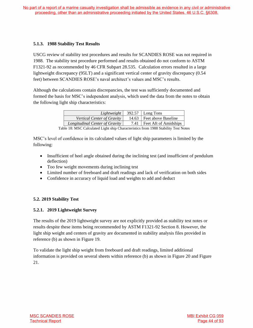
5.1.3. 1988 Stability Test Results
USCG review of stability test procedures and results for SCANDIES ROSE was not required in
1988. The stability test procedure performed and results obtained do not conform to ASTM
F1321-92 as recommended by 46 CFR Subpart 28.535. Calculation errors resulted in a large
lightweight discrepancy (95LT) and a significant vertical center of gravity discrepancy (0.54
feet) between SCANDIES ROSE’s naval architect’s values and MSC’s results.
Although the calculations contain discrepancies, the test was sufficiently documented and
formed the basis for MSC’s independent analysis, which used the data from the notes to obtain
the following light ship characteristics:
Lightweight 392.57 Long Tons
Vertical Center of Gravity 14.63 Feet above Baseline
Longitudinal Center of Gravity 7.41 Feet Aft of Amidships Table 18: MSC Calculated Light ship Characteristics from 1988 Stability Test Notes
MSC’s level of confidence in its calculated values of light ship parameters is limited by the
following:
• Insufficient of heel angle obtained during the inclining test (and insufficient of pendulum
deflection)
• Too few weight movements during inclining test
• Limited number of freeboard and draft readings and lack of verification on both sides
• Confidence in accuracy of liquid load and weights to add and deduct
5.2. 2019 Stability Test
5.2.1. 2019 Lightweight Survey
The results of the 2019 lightweight survey are not explicitly provided as stability test notes or
results despite these items being recommended by ASTM F1321-92 Section 8. However, the
light ship weight and centers of gravity are documented in stability analysis files provided in
reference (b) as shown in Figure 19.
To validate the light ship weight from freeboard and draft readings, limited additional
information is provided on several sheets within reference (b) as shown in Figure 20 and Figure
21.
No part of a report of a marine casualty investigation shall be admissible as evidence in any civil or administrative proceeding, other than an administrative proceeding initiated by the United States. 46 U.S.C. §6308.
MSC SCANDIES ROSE Technical Report
MBI Exhibit CG 059 Page 44 of 93

Using the notes in Figure 19 and Figure 20, the “weight to deduct” is calculated so that the
weight and longitudinal center of gravity can be calculated in the as-tested condition (Condition
0).
The total weight to deduct from Table 19 and the light ship weight used in Figure 19 were used
by MSC to calculate the weight and LCG of SCANDIES ROSE during the 2019 stability test
because this was not provided in reference (b). The as-tested (Condition 0) weight was assumed
to be 587.73 Long Tons with an LCG of 2.96 feet aft of amidships.
Several disparate freeboard and draft measurements are provided in reference (b) as shown in
Table 20. Using reference (a), these measurement sets provide a range of weights for the vessel
as tested (Condition 0) from 606.52 LT to 611.47 LT. It is not known which freeboards were
actually measured during the lightweight survey performed at the time of the stability test in
2019. MSC assumed that the freeboards within the larger list of depths, freeboards, and drafts at
Figure 19: 2019 stability analysis (provided within ref (b)) noting the light ship weight and centers of gravity,
dated 13-May-2019
Figure 20: Ref (b) notes with apparent weights to deduct. Undated but assumed to be relevant to the 2019
stability test.
No part of a report of a marine casualty investigation shall be admissible as evidence in any civil or administrative proceeding, other than an administrative proceeding initiated by the United States. 46 U.S.C. §6308.
MSC SCANDIES ROSE Technical Report
MBI Exhibit CG 059 Page 45 of 93

the top of Figure 21 represent data as measured during the lightweight survey because these
measurements do not result in a perfectly straight waterline plot—indicative of rough data as
measured in the field. However, observed erasures and lack of context for the values in Figure
21 decrease confidence in these values.
Figure 21: ref (b) notes with apparent draft and freeboard readings and weights to deduct. Weights to deduct
mostly correspond to those in Figure 20 (see Table 19). Undated but assumed to be relevant to the 2019 stability
test.
GHS command
for defining
drafts
MSC assumed
this data was
recorded during
the lightweight
survey
No part of a report of a marine casualty investigation shall be admissible as evidence in any civil or administrative proceeding, other than an administrative proceeding initiated by the United States. 46 U.S.C. §6308.
MSC SCANDIES ROSE Technical Report
MBI Exhibit CG 059 Page 46 of 93

Figure 22: ref (b) notes plotting the location and position of lightweight survey freeboard and draft readings on SCANDIES ROSE dated 12-Apr-2019
No part of a report of a marine casualty investigation shall be admissible as evidence in any civil or administrative proceeding, other than an administrative proceeding initiated by the United States. 46 U.S.C. §6308.
MSC SCANDIES ROSE Technical Report
MBI Exhibit CG 059 Page 47 of 93

Item Weight (LT) LCG (feet)
Inclining Weights 6.53 4.00f
Personnel 0.41 2.00f
Misc. on Deck Weights 1.34 12.00f
WATER.P Tank 30% Capacity 2000 gal 7.46 28.45a
WATER.S Tank 30% Capacity 2000 gal 7.46 28.45a
DAYTANK.P Tank 81% Capacity 3000 gal 9.67 56.08a
AFTFUEL.S Tank 27% Capacity* 2000 gal* 6.53 44.78a
Total Weight to Deduct 39.40 30.87a
* Note: 27% capacity in the Starboard Aft Fuel Tank is equivalent to 2,000 gallons/6.53 LT of diesel as
noted by ref (n), which indicates the aft fuel tank capacity is 7,390 gallons. ref (b) indicates 27% and
3,000 gallons are loaded in this tank. 3,000 gallons would be equivalent to 41% of capacity with 9.80
LT of diesel according to the Capacity Plan, Ref N. Table 19: Weights to Deduct from ref (b) 2019 Stability Test Notes
Light ship is determined by applying the weight to deduct to the as-tested (Condition 0) weight
of the vessel as shown in Table 22. Using the freeboard measurement sets in reference (b), light
ship weight ranges from 567.12 LT to 572.07. However, reference (b) indicates 548.32 LT was
used in stability calculations shown in Figure 19. This light ship weight is between 18.80 LT to
23.75 LT less than calculated during the stability test and approximately 150 LT heavier than the
light ship weight in 1988.
In addition to using a light ship weight that is not supported by the stability test measurements,
documentation within reference (b) indicate the following items that do not conform to
recommended stability test procedures:
• SCANDIES ROSE had excessive trim (>2 feet) during the lightweight survey and
was not “as close as possible to even list and design trim” as recommended (ASTM
F1321-92 section 5.4)
• Five freeboards were apparently recorded (Figure 21) but not on each side as
recommended (ASTM F1321-92 section 7.1.2.1)
• Draft marks were apparently not taken, although extreme baseline drafts are shown
in Figure 22 (ASTM F1321-92 section 7.1.2.1)
• A survey of the vessel to “identify all items that need to be added to the vessel,
removed from the vessel, or relocated on the vessel” was apparently not complete as
indicated by Figure 23 (ASTM F1321-92 section 7.1.1.4)
• Freeboards do not note the inclusion of coaming heights or deck thickness (ASTM
F1321-92 sections 7.1.2.1 and 7.1.2.8)
• No report, data sheets, or calculations are provided (ASTM F1321-92 sections 8.1
through 8.3)
A lightweight of 578.33 long tons with an LCG of 0.52 feet aft of amidships is calculated as item
(d) of Table 22. These values are calculated using MSC’s model from the freeboards listed in
Figure 21; this list of depths, freeboards, and calculated drafts is the typical way that raw data is
No part of a report of a marine casualty investigation shall be admissible as evidence in any civil or administrative proceeding, other than an administrative proceeding initiated by the United States. 46 U.S.C. §6308.
MSC SCANDIES ROSE Technical Report
MBI Exhibit CG 059 Page 48 of 93

recorded during a lightweight survey and these values are the most supported within the stability
test notes. However, this light ship weight is 183 long tons (46%) heavier than that found in
1988. Possible sources of this discrepancy include errors in freeboard readings or weights to
deduct.
A letter to Mr. Mattesen within reference (b) acknowledges the heavier than expected
lightweight after the stability test (Figure 23). This letter cites several possible discrepancies
including missing weights, weight growth, and tankage.
Figure 23: Letter from Mr. Culver to Dan Mattesen dated 17 May 2019 (found within ref (b)), indicating that
unknown weight may have been onboard during the stability test
No part of a report of a marine casualty investigation shall be admissible as evidence in any civil or administrative proceeding, other than an administrative proceeding initiated by the United States. 46 U.S.C. §6308.
MSC SCANDIES ROSE Technical Report
MBI Exhibit CG 059 Page 49 of 93

Longitudinal Location (feet from
amidships) → 61.5a 18a 8a 2f 12f 22f 64.5f Calculated Displacement and LCG
using ref (a) GHS Model Source ↓ Reading
(a) ref (b) List of Depths,
Freeboard, Drafts
(Top of Figure 21)
Freeboard 5.125 5.400 5.570 5.830 6.230 Displacement: 611.47 LT
Draft 9.225 8.930 8.760 8.870 8.870 LCG: 2.78 ft aft MS
Error -0.140 0.078 0.171 -0.016 -0.093 Least-squared fit, R2: 0.4816
(b) ref (b) GHS Command
for Defining Drafts
(Line 10 of Figure 21)
Freeboard Displacement: 606.52 LT
Draft 9.230 8.760 LCG: 5.51 ft aft MS
Error 0.000 0.000 Least-squared fit, R2: N/A
(c) ref (b) Plotted Data
(Figure 22)
Freeboard 5.125 5.319 5.513 6.079 6.693 Displacement: 608.99 LT
Draft 10.050 9.225 9.011 8.817 8.621 8.407 7.603 Longitudinal Center of
Gravity: 4.52 ft aft MS
Error 0.006 -0.018 0.001 -0.001 0.000 0.019 -0.006 Least-squared fit, R2: 0.9998
Cell Shading Represents Data Provided in ref (b), all others calculated by MSC
Table 20: Disparate freeboard and draft measurements from 2019 stability test using ref (a) GHS model to calculate values
Cell Shading Represents Data Provided in ref (b), All Others Calculated by MSC
Table 21: Disparate freeboard and draft measurements from 2019 stability test using MSC’s model to calculate values
Longitudinal Location (feet from
amidships) → 61.5a 18a 8a 2f 12f 22f 64.5f Calculated Displacement and LCG
using MSC’s GHS Model Source ↓ Reading
(d) ref (b) List of Depths,
Freeboard, Drafts
(Top of Figure 21).
Drafts Calculated from MSC
Model
Freeboard 5.125 5.400 5.570 5.830 6.230 Displacement: 617.73 LT
Draft 9.275 8.970 8.800 8.760 8.780 LCG: 2.43 ft aft MS
Error -0.118 0.067 0.117 0.037 -0.103 Least-squared fit, R2: 0.7656
(e) ref (b) Plotted Data
(Figure 22).
Drafts Calculated from MSC
Model
Freeboard 5.125 5.319 5.513 6.079 6.693 Displacement: 612.38 LT
Draft 10.050 9.275 9.051 8.857 8.511 8.317 7.603 LCG: 3.59 ft aft MS
Error 0.026 -0.069 -0.045 -0.051 0.095 0.089 -0.047 Least-squared fit, R2: 0.9919
No part of a report of a marine casualty investigation shall be admissible as evidence in any civil or administrative proceeding, other than an administrative proceeding initiated by the United States. 46 U.S.C. §6308.
MSC SCANDIES ROSE Technical Report
MBI Exhibit CG 059 Page 50 of 93

Calculation Source
Weight
Magnitude
(LT)
Longitudinal
Center of
Gravity
(Feet,
Positive Aft)
Longitudinal
(Trimming)
Moment
(Feet*LT)
Co
nd
itio
n 0
(W
eig
ht
as
Tes
ted
)
(a) ref (b) List of Depths, Freeboard, Drafts
(Top of Figure 21), Using ref (a) 611.47 2.78 1699.89
(b) ref (b) GHS Command for Defining Drafts
(Line 10 of Figure 21), Using ref (a) 606.52 5.51 3341.93
(c) ref (b) Plotted Data (Figure 22),
Using ref (a) 608.99 4.52 2752.63
(d) ref (b) of Depths, Freeboard, Drafts (Top
of Figure 21).
Drafts Calculated from MSC Model
617.73 2.43 1501.08
(e) ref (b) Plotted Data (Figure 22).
Drafts Calculated from MSC Model 612.38 3.59 2198.44
Weight to Deduct from 2019 Test Notes
(Table 19): 39.40 30.87 1216.161
Weight to Add from 2019 Test Notes: 0 0 0
Co
nd
itio
n 1
(L
igh
t S
hip
Wei
gh
t)
(a) ref (b) List of Depths, Freeboard, Drafts
(Top of Figure 21), Using ref (a) 572.07 0.85 483.73
(b) ref (b) GHS Command for Defining Drafts
(Line 10 of Figure 21), Using ref (a) 567.12 3.75 2125.76
(c) ref (b) Plotted Data (Figure 22),
Using ref (a) 569.59 2.70 1536.47
(d) ref (b) List of Depths, Freeboard, Drafts
(Top of Figure 21).
Drafts Calculated from MSC Model
578.33 0.52 300.73
(e) ref (b) Plotted Data (Figure 22).
Drafts Calculated from MSC Model 572.98 1.74 996.99
Weight Actually Used in ref (b) Calculations
(Figure 19), Not Supported by Test Notes 548.32 3.30 1809.46
Table 22: Calculation of light ship weight (Condition 1) from 2019 Stability Test Notes
No part of a report of a marine casualty investigation shall be admissible as evidence in any civil or administrative proceeding, other than an administrative proceeding initiated by the United States. 46 U.S.C. §6308.
MSC SCANDIES ROSE Technical Report
MBI Exhibit CG 059 Page 51 of 93

5.2.2. 2019 Inclining Test
Calculation of the vertical center of gravity from an inclining test is dependent upon the
calculation of vessel lightweight; errors in the weight calculation propagate into the vertical
center of gravity calculation.
Figure 24 documents the inclining test performed on SCANDIES ROSE in 2019. This inclining
test does not conform to the following items recommended by ASTM F1321-92:
• Maximum pendulum deflection is low at a maximum of 5.43 inches (6 inches is
recommended by ASTM F1321-92 section 5.6.2)
• The plot of points contained in Figure 24 would not cross the origin as shown in Figure
25 and does not appear to be a “best fit” through the points. The pendulum deflection
with zero weight shift should have been recorded twice (ASTM F1321-92 section
7.1.3.8). Figure 25 would have a point on the origin if the “4th Trial” entry in Figure 24
was accurate. Lack of zero crossing indicates a potential error or steady heeling moment
which could be verified if zero weight shift readings were obtained and plotted.
Figure 24: 2019 test notes recording weight shifts and inclination angles (from ref (b))
No part of a report of a marine casualty investigation shall be admissible as evidence in any civil or administrative proceeding, other than an administrative proceeding initiated by the United States. 46 U.S.C. §6308.
MSC SCANDIES ROSE Technical Report
MBI Exhibit CG 059 Page 52 of 93

The slope of the plot provided in Figure 25 represents the ship’s transverse GM multiplied by the
total weight of the vessel (this product is referred to as “GMTM”) and this is how the vertical
center of gravity is calculated. A slope of 2067 foot⸱tons is indicated in Figure 25.
Using the data from Figure 24, MSC independently plotted and calculated the slope by least-
squared linear regression. If the measurement for “Trial 4” is correct, the slope is 2042.4
foot⸱tons. If the measurement provided for “Trial 4” is erroneous (as indicated by the lack of
recorded pendulum readings in Figure 24), the slope is calculated as 2043.4 foot⸱tons by MSC.
These GMTM results are close in value and the latter calculated value of 2043.4 foot⸱tons is
considered most accurate.
Table 23 shows the method for calculating lightweight VCG. There is no documentation within
available test notes in reference (b) to support the values used in stability analysis to generate
reference (c). Table 23 indicates that the vertical center of gravity ranges from a minimum or
most favorable of 14.69 feet (as used in the ref (b) stability analysis) to a maximum of 15.62 feet
(the most accurate value supported by test notes and the MSC computer model).
Figure 25: Stability test notes plotting heeling moments and tangents of inclining from 2019 (ref (b))
No part of a report of a marine casualty investigation shall be admissible as evidence in any civil or administrative proceeding, other than an administrative proceeding initiated by the United States. 46 U.S.C. §6308.
MSC SCANDIES ROSE Technical Report
MBI Exhibit CG 059 Page 53 of 93

Weight
Source
Condition
0 Weight
(LT)
GMTM
Source
GMTM
(ft*LT) GM (feet)
Formal
Free
Surface
Corr.
(feet)
Condition
0 KM
(from
model,
feet)
Condition
0 VCG
(feet)
Condition
0 Vert.
Moment
(ft*LT)
Sum of
Weight
to Add/
Remove
(LT)
Moment
of Wt. to
Add/
Remove
(ft*LT)
Light
Weight
(LT)
Light
Weight
VCG
(feet)
Item (a)
from Table
20
611.47 ref (b) 2067 3.38 0.068 18.61 15.16 9270.86 -39.40 -359.53 572.07 15.58
Item (d)
from Table
21
617.73 ref (b) 2067 3.35 0.067 18.24 14.83 9158.80 -39.40 -359.53 578.33 15.21
Item (a)
from Table
20
611.47 MSC 2043.4 3.34 0.068 18.61 15.20 9294.46 -39.40 -359.53 572.07 15.62
Item (d)
from Table
21
617.73 MSC 2043.4 3.31 0.067 18.24 14.86 9182.40 -39.40 -359.53 578.33 15.26
ref (b) 2019
Loading
Conditions
? ? ? ? ? ? ? ? ? ? 548.32 14.69
Table 23: Variability in vertical center of gravity (VCG) calculations with lightweights and incline plots
No part of a report of a marine casualty investigation shall be admissible as evidence in any civil or administrative proceeding, other than an administrative proceeding initiated by the United States. 46 U.S.C. §6308.
MSC SCANDIES ROSE Technical Report
MBI Exhibit CG 059 Page 54 of 93

5.2.3. 2019 Stability Test Results
Although an inclining test was required after substantial alterations between 1988 and 2019,
USCG review of stability test procedures and results for SCANDIES ROSE was not required.
Documentation within reference (b) indicates that the stability test procedure performed did not
conform with ASTM F1321-92, as recommended by 46 CFR Subpart 28.535. Available
documentation within reference (b) appears to use a lightweight and center of gravity that are not
supported by the stability test performed in 2019.
The stability test in 2019 was not well documented, and MSC’s independent analysis attempted
to use the best available information to calculate the following approximate light ship
characteristics:
Lightweight 578.33 Long Tons
Vertical Center of Gravity 15.26 Feet above Baseline
Longitudinal Center of Gravity 0.52 Feet Aft of Amidships Table 24: MSC calculated light ship characteristics from 2019 stability test notes
MSC has a low level of confidence in the light ship weight characteristics in Table 24. MSC’s
level of confidence in these values is limited by the following:
• Lack of confidence in weights to deduct during the stability test (this concern is shared in
the letter provided as Figure 23)
• Spacing of freeboard measurements along the hull and apparent lack of verification on
both sides
• Potential errors in measurement or recording of freeboard values
• Excessive additional light ship weight of vessel as compared to 1988 stability test results
(45% higher).
Of the above items, the excessive weight growth from 1988 is the most concerning. Figure 23
notes that there may have been additional weight in the holds that was unaccounted for during
the deadweight survey. Using the light ship weight and centers of gravity from 2019 and 1988,
MSC calculated the hypothetical amount of weight and average location of this additional weight
in Table 25.
Change in Lightweight 180.09 Long Tons
VCG of Changed Weight 16.65 Feet above Baseline
LCG of Changed Weight 14.72 Feet Fwd. of
Amidships Table 25: MSC calculated weight change and centers of gravity from 1988 to 2019
The average center of gravity of the additional weight corresponds to a longitudinal location near
the port side crane pedestal and vertical location near the deck level. This weight and center of
gravity could be achieved in many different ways including (but not limited to) structural
changes to the hull (possibly the additional height added to the forecastle or crane modifications)
No part of a report of a marine casualty investigation shall be admissible as evidence in any civil or administrative proceeding, other than an administrative proceeding initiated by the United States. 46 U.S.C. §6308.
MSC SCANDIES ROSE Technical Report
MBI Exhibit CG 059 Page 55 of 93

and loaded tanks or holds not discovered during the deadweight survey as noted in Figure 23.
The apparent change in weight and center of gravity may also indicate erroneous measurements
in either the lightweight survey or inclining.
5.3. Stability Test Conclusions
Significant errors exist in both the 1988 and 2019 lightweight surveys as part of their respective
stability tests. These surveys provide the light ship weight and longitudinal center of gravity of
the vessel. Reference (b) does not contain information from either the 1988 or 2019 test data that
supports the light ship weights used in the stability calculations conducted by the owner’s naval
architect. MSC’s low confidence in the 2019 lightweight survey carries forward though the
inclining test and results in overall low confidence in the stability test results.
Lightweight
(Long Tons)
LCG (Ft. Aft
of Amidships)
VCG (Ft.
Abv
Baseline)
Notes
1988 Values Used in ref (b)
Calculations 485.35 10.74 14.09
Not Supported by
Test Notes
1988 Values from MSC Review
of Test Notes 392.57 7.41 14.63 Moderate Confidence
2019 Values Used in ref (b)
Calculations 548.32 3.30 14.69
Not Supported by
Test Notes
2019 Values from MSC Review
of Test Notes 578.33 0.52 15.26 Low Confidence
Table 26: Results of 1988 and 2019 Stability Tests
No part of a report of a marine casualty investigation shall be admissible as evidence in any civil or administrative proceeding, other than an administrative proceeding initiated by the United States. 46 U.S.C. §6308.
MSC SCANDIES ROSE Technical Report
MBI Exhibit CG 059 Page 56 of 93

6. SCANDIES ROSE STABILITY CRITERIA
SCANDIES ROSE was required to meet 46 CFR Part 28 Subpart E, Stability Requirements for
Commercial Fishing Industry Vessels which include the following operational stability criteria:
• 46 CFR 28.530: Stability Instructions
• 46 CFR 28.565: Water on Deck
• 46 CFR 28.570: Intact Righting Energy
• 46 CFR 170.173(c): Alternate Intact Criteria (per 46 CFR 28.570(c))
• 46 CFR 28.575: Severe Wind and Roll
Loading conditions for SCANDIES ROSE are documented within the 1988 and 2019 Stability
Instructions and Stability Books (ref (b) and (c)). Two additional loading conditions were
provided to MSC by the Marine Board of Investigation—these conditions are estimates of the
loading condition during the casualty voyage.
Items from Sections 4 and 5 of this report (hydrostatic modeling and stability tests) provide the
required information and means by which to evaluate stability criteria for each loading condition.
Errors in the hydrostatic model and stability test results propagate into the evaluation of stability
criteria.
6.1. Stability Instructions Provided by Mr. Culver
46 CFR 28.530 requires that SCANDIES ROSE maintain stability instructions developed by a
qualified individual. This regulation requires:
Each vessel must be provided with stability instructions which provide the
master or individual in charge of the vessel with loading constraints and
operating restrictions which maintain the vessel in a condition which meets the
applicable stability requirements of this subpart.
To provide flexibility, 46 CFR 28.530(d) provides a list of specific information that MAY be
included in the stability instructions.
Two distinct documents with “Instructions to Master” of SCANDIES ROSE were made
available: stability instructions from 1988 are shown in Figure 26 found within reference (b), and
stability instructions provided in 2019 in Figure 27 found within reference (c).
In the 1988 stability instructions, the prescriptive limits of SCANDIES ROSE can be
summarized as:
No part of a report of a marine casualty investigation shall be admissible as evidence in any civil or administrative proceeding, other than an administrative proceeding initiated by the United States. 46 U.S.C. §6308.
MSC SCANDIES ROSE Technical Report
MBI Exhibit CG 059 Page 57 of 93

• A maximum of 220 crab pots in up to 5 tiers OR deck load not to exceed 160,000 lbs.3
• A maximum of four tiers of pots in icing conditions
Other limits are provided, but it is not clear if they are requirements. These include:
• Fuel volume when leaving port (50,000 gallons)
• Water tanks full when leaving port
• The best stability condition for cargo holds is filling center only or center and aft
• Use of fuel from one wing tank pair at a time sequencing burn off to minimize trim
(maximum trim not given).
2019 stability instructions (ref (c)) provide the following prescriptive stability limits:
• 208 pots (of 835 lbs. each) can be carried on deck with one or two holds flooded
• 168 pots can be carried on deck with all three holds flooded and the forward wing fuel
tanks empty
• Flooded holds must be full or empty
• Freeboard must not be less than 6 inches at any point
3 It is not clear if 220 crab pots would equal a deck load of 160,000 lbs., which would equate to 727 lbs. per pot
No part of a report of a marine casualty investigation shall be admissible as evidence in any civil or administrative proceeding, other than an administrative proceeding initiated by the United States. 46 U.S.C. §6308.
MSC SCANDIES ROSE Technical Report
MBI Exhibit CG 059 Page 58 of 93

Figure 26: 1988 Stability Instructions for SCANDIES ROSE from ref (b)
No part of a report of a marine casualty investigation shall be admissible as evidence in any civil or administrative proceeding, other than an administrative proceeding initiated by the United States. 46 U.S.C. §6308.
MSC SCANDIES ROSE Technical Report
MBI Exhibit CG 059 Page 59 of 93

Figure 27: 2019 Stability Instructions for SCANDIES ROSE from ref (c)
No part of a report of a marine casualty investigation shall be admissible as evidence in any civil or administrative proceeding, other than an administrative proceeding initiated by the United States. 46 U.S.C. §6308.
MSC SCANDIES ROSE Technical Report
MBI Exhibit CG 059 Page 60 of 93

6.2. Stability Criteria Assumptions
6.2.1. Load Line Assumption
46 CFR Chapter I, Subchapter E did not require SCANDIES ROSE to have a load line.
However, SCANDIES ROSE sister ship PATRICA LEE was issued a load line by the American
Bureau of Shipping in 1996 as shown in Figure 28 and provided to MSC by the American
Bureau of Shipping (ref (p)). This load line requires a winter freeboard of 1 foot, 4.75 inches
from the main deck at amidships. As a reference point on SCANDIES ROSE, this load line is
incorporated into stability evaluations at a height of 13.0 feet above the baseline to correspond
with 1 foot 4.75 inches from the molded deck line at amidships. Although a load line was not
compulsory for SCANDIES ROSE, the sister ship load line provides a regulatory measure of
reserve buoyancy that is an alternative to the criteria in 46 CFR Chapter I Subchapter E.
Because the load line was an alternate criterion and not required for SCANDIES ROSE,
submerged load line results are highlighted in yellow instead of red in Table 29 to Table 46.
6.2.2. Initial Heel Angles After Loading
Off center or asymmetric consumable tanks such as the fuel day tank, aft fuel tanks, lube oil
tank, and sewage tank result in initial heel angles for many of SCANDIES ROSE’s loading
conditions. MSC assumed the SCANDIES ROSE was upright with zero initial heel in all
loading conditions by shifting cargo transversely to correct heel. When crab pots are loaded, this
transverse shift is calculated and applied for the top tier pot weights first and progress to lower
tiers if needed to attain enough magnitude in righting moment. When tendering equipment is
specified in sample loading conditions, the transverse weight shift is achieved by loading deck
equipment off centerline to correct the vessel’s heel angle.
The assumption that SCANDIES ROSE was always upright in a static equilibrium condition for
all conditions of loadings is not conservative; it is likely that off-center tanks, especially the
constant use of the fuel oil day tank on the port side, frequently caused a heel angle for
SCANDIES ROSE. Righting arms for a vessel with an off-centerline weight condition are
subject to a cosine correction which can significantly reduce righting area and range (angles) of
stability.
No part of a report of a marine casualty investigation shall be admissible as evidence in any civil or administrative proceeding, other than an administrative proceeding initiated by the United States. 46 U.S.C. §6308.
MSC SCANDIES ROSE Technical Report
MBI Exhibit CG 059 Page 61 of 93

Figure 28: International Load Line Certificate Issued to PATRICIA LEE in 1996 (ref (p))
No part of a report of a marine casualty investigation shall be admissible as evidence in any civil or administrative proceeding, other than an administrative proceeding initiated by the United States. 46 U.S.C. §6308.
MSC SCANDIES ROSE Technical Report
MBI Exhibit CG 059 Page 62 of 93

6.2.3. 46 CFR 28.540 Free Surface Assumption for All Criteria
46 CFR 28.540 requires the use of either formal free surface effect or calculation of free surface
using the moment of transference method to evaluate the transverse weight shift in tanks as the
vessel heels. The moment of transference method results in lesser weight shifts for large angles
of heel and less negative impact to righting area in general. MSC approximated the moment of
transference method by calculating the true weight shifts in each tank and assigning free surface
as the product of tank waterplane moment of inertia, tank permeability, and density of tank
contents; this process is the “true free surface” calculation method within GHS software.
It is not known if wing fuel tanks had cross connection piping. Wing tank pairs were treated as
individual tanks by MSC for the purpose of free surface moments. This assumption is less
conservative and results in lower free surface moments than assuming the tanks are cross
connected.
6.2.4. 46 CFR 28.550 Icing Assumptions
Icing is discussed in Sections 4.3.3 and 4.3.6. MSC’s model applied vertical surface ice weight
to the sides and ends of each crab pot tier that is loaded. MSC’s model applied horizontal
surface ice weight to the highest tier of pots that are loaded as indicated in Section 4.3.6. The
owner’s naval architect’s model, reference (a), requires the use of a fixed weight and center of
gravity for ice which was applied using the weights documented in reference (b).
6.2.5. 46 CFR 28.555 Freeing Ports
The size of freeing ports was evaluated below in Section 6.4. For these measurements, the deck
edge (sheer line) of the MSC hydrostatics model was used to evaluate main deck bulwark
lengths. A procedure for determining required sheer (longitudinal main deck curvature) is not
noted in 46 CFR 28.555 (g). SCANDIES ROSE was assumed to have sufficient sheer for the
purpose of 46 CFR 28.555 (g). The bycatch chute was assumed to provide no contribution to
freeing port area.
6.2.6. 46 CFR Watertight and Weathertight Integrity Assumptions
Both reference (a) and MSC’s model assumed that the hull below the main deck, enclosed
forecastle, and enclosed poop are watertight. All doors leading to these enclosed buoyant
No part of a report of a marine casualty investigation shall be admissible as evidence in any civil or administrative proceeding, other than an administrative proceeding initiated by the United States. 46 U.S.C. §6308.
MSC SCANDIES ROSE Technical Report
MBI Exhibit CG 059 Page 63 of 93

volumes were assumed to be watertight and closed. No buoyancy is assumed for the house and
superstructure. The skeg, included in MSC’s model, is assumed to be non-buoyant.
All compartment and tank vents are assumed to have effective check valves that prevent water
ingress.
The only known downflooding points were assumed to be the engine room vents behind the
pilothouse stairs (see section 4.3.7). Although references (a) through (c) did not include these
points for stability analysis, MSC added them to the reference (a) model for the purpose of
evaluating all stability criteria; this model with added downflooding points is named “CulverDF”
in results tables (Table 29 to Table 46).
6.2.7. 46 CFR 28.570 Intact Righting Energy Assumptions
46 CFR 28.570(a)(7) requires a range of positive righting arms to 60° of heel unless hatches are
normally kept closed or open holds are flooded. Because Stability Instructions for SCANDIES
ROSE require the holds to be full or closed and empty, the lesser criteria of 46 CFR 28.570(b)(3)
which specifies a range of positive righting arms to 50° of heel is required.
46 CFR 28.570(c) allows the Rahola Criteria listed in 46 CFR 170.173(c) to be used as a suitable
alternative to the Torremolinos Criteria given in 46 CFR 28.570(a). Because this is an alternate
standard and not required, failing conditions for these alternate criteria are shown in yellow
rather than red in results tables (Table 29 to Table 46).
6.2.8. 46 CFR 28.575 Severe Wind and Roll Assumptions
MSC evaluated SCANDIES ROSE for the Severe Wind and Roll Criteria using the International
Maritime Organization (IMO) Severe Wind and Roll function within GHS. Both IMO Severe
Wind and Roll Criteria (from Resolution A.562(14)) and 46 CFR 28.575 criteria follow the same
procedure, applying a “gust” wind speed to the lateral area (windage) of the hull that
logarithmically increases as a function of the height above waterline. For a vessel that operates
on “other than protected waters,” 46 CFR 28.575 (b) requires the gust wind speed to be:
𝑉(ℎ) = 85.3[0.124 × ln(0.3048 × ℎ) + 0.772] (in feet per second)
At a nominal height of 33 feet above the waterline, this gust wind speed is 53.4 knots (90.2 feet
per second). The area that the wind speed acts upon was calculated by breaking up the lateral
plane area or windage into horizontal bands that are 0.25 feet high. Every 0.25 feet of height
above the waterline, the wind velocity was calculated using the above formula with the windage
No part of a report of a marine casualty investigation shall be admissible as evidence in any civil or administrative proceeding, other than an administrative proceeding initiated by the United States. 46 U.S.C. §6308.
MSC SCANDIES ROSE Technical Report
MBI Exhibit CG 059 Page 64 of 93

area calculated with consideration for shielded components (e.g. crab pots on deck could prevent
wind pressure from acting on a crane’s windage).
Wind speed must be used with a coefficient of drag in order to define a pressure acting on the
lateral plane area. Although the drag coefficient is not explicitly defined within 46 CFR 28.575,
MSC calculated it as 1.2 using the wind heeling lever formula specified by the regulation.
MSC evaluated the k-coefficient required in 46 CFR 28.575(c) by calculating the lateral plane
area of the skeg (98.8 square feet) and treating it as a bar keel for the purpose of the regulation.
The k-coefficient is evaluated using either prescribed values for round hulls or hard-chine hulls
or using the third table of Tables 28.575 in 46 CFR. Entering values for this table include the
area of keel and loading condition waterplane length and breadths. Using SCANDIES ROSE’s
loading condition waterline lengths and breadths, a k-coefficient value of approximately 0.79 is
found. Because SCANDIES ROSE has sharp bilges (chines), a k-coefficient of 0.7 is allowed.
The k-coefficient is less conservative with smaller values of “k.” MSC’s analysis assumed the
lower 0.7 value for the k-coefficient.
For each load condition evaluated in this report, all 46 CFR 28.575 coefficients are presented in
the Appendices under the heading “IMO parameters.”
6.2.9. 46 CFR 28.580 Unintentional Flooding Assumptions
Unintentional flooding (damage) criteria does not apply to SCANDIES ROSE because these
criteria are limited to vessels that were “built on or after September 15, 1991.” Although
SCANDIES ROSE underwent some modifications after 1991, modification or alteration is not a
factor considered in the regulatory applicability of 46 CFR 28.580.
No part of a report of a marine casualty investigation shall be admissible as evidence in any civil or administrative proceeding, other than an administrative proceeding initiated by the United States. 46 U.S.C. §6308.
MSC SCANDIES ROSE Technical Report
MBI Exhibit CG 059 Page 65 of 93

Table 27: MSC model tank load differences from ref (b) load condition specification
Loading Condition
Hyd
ro-S
tati
cs M
od
el
Tan
k fw
dw
ing
(s)
Wei
ght
Dif
f.
(LT)
Tan
k fw
dw
ing
(p)
Wei
ght
Dif
f.
(LT)
Tan
k m
idw
ing
(s)
Wei
ght
Dif
f.
(LT)
Tan
k m
idw
ing
(p)
Wei
ght
Dif
f.
(LT)
Tan
k af
twin
g (s
) W
eigh
t D
iff.
(LT)
Tan
k af
twin
g (p
) W
eigh
t D
iff.
(LT)
Tan
k w
ater
(s)
Wei
ght
Dif
f.
(LT)
Tan
k w
ater
(p
) W
eigh
t D
iff.
(LT)
Tan
k af
tfu
el (
s) W
eigh
t D
iff.
(LT)
Tan
k af
tfu
el (
p)
Wei
ght
Dif
f.
(LT)
Tan
k Lu
beo
il (p
) W
eigh
t D
iff.
(LT)
Tan
k d
ayta
nk
(p)
Wei
ght
Dif
f.
(LT)
Tan
k se
wag
e (s
) W
eigh
t D
iff.
(LT)
Tan
k d
blb
tmc
Wei
ght
Dif
f. (
LT)
Tota
l Dif
fere
nce
(LT
)
% D
iffe
ren
ce (
of
Dis
pla
cem
ent,
LT)
1988 Stability Book Condition 1:
Departure, Full Fuel, 212 PotsMSC -2.8 -2.8 -1.9 -1.9 -1.7 -1.7 0.0 0.0 0.0 -1.0 0.0 0.0 0.0 0.0 13.8 1.54%
1988 Stability Book Condition 2:
Arrival on Fishing Grounds, 75%
Fuel and Water
MSC -2.8 -2.8 -1.9 -1.9 -1.7 -1.7 0.0 0.0 0.0 0.0 0.0 0.0 0.0 0.0 12.8 1.32%
1988 Stability Book Condition 3:
Fishing, Moving Pots, 50% Fuel,
212 Pots, 3 Holds Full
MSC 0.0 0.0 0.0 0.0 -1.7 -1.7 0.0 0.0 0.0 0.0 0.0 0.0 0.0 0.0 3.4 0.33%
1988 Stability Book Condition 4:
Fishing, 25% FuelMSC 0.0 0.0 0.0 0.0 0.0 0.0 0.0 0.0 0.0 0.0 0.0 0.0 0.0 0.0 0.0 0.00%
1988 Stability Book Condition 5:
Burned Out, 10% Fuel, 50 Pots, 3
Holds Full
MSC 0.0 0.0 0.0 0.0 0.0 0.0 0.0 0.0 0.0 0.0 0.0 0.0 0.0 0.0 0.0 0.00%
1988 Stability Book Condition 6:
Departure, Full Fuel, 3 Holds Full,
168 Pots
MSC -2.8 -2.8 -1.9 -1.9 -1.7 -1.7 0.0 0.0 0.0 0.0 0.0 0.0 0.0 0.0 12.8 1.16%
2019 Stability Book Condition 1:
Max Consumables, 208 Pots,
Holds 2 and 3 full
MSC 0.0 0.0 -0.3 -0.3 -2.1 -2.1 0.0 0.0 0.0 0.0 0.0 0.0 0.0 0.0 4.8 0.45%
2019 Stability Book Condition 2:
75% Consumables, 208 Pots,
Holds 2 and 3 Full
MSC 0.0 0.0 0.0 0.0 -2.1 -2.1 0.0 0.0 0.0 0.0 0.0 0.0 0.0 0.0 4.2 0.41%
2019 Stability Book Condition 3:
50% Consumables, 208 Pots,
Holds 2 and 3 Full
MSC 0.0 0.0 0.0 0.0 -2.1 -2.1 0.0 0.0 0.0 0.0 0.0 0.0 0.0 0.0 4.2 0.41%
2019 Stability Book Condition 4:
25% Consumables, 208 Pots,
Holds 2 and 3 Full
MSC 0.0 0.0 0.0 0.0 -2.1 -2.1 0.0 0.0 0.0 0.0 0.0 0.0 0.0 0.0 4.2 0.43%
2019 Stability Book Condition 5:
10% Consumables, 208 Pots,
Holds 2 and 3 Full
MSC 0.0 0.0 0.0 0.0 0.0 0.0 0.0 0.0 0.0 0.0 0.0 0.0 0.0 0.0 0.0 0.00%
2019 Stability Book Condition 6:
Max Consumables, Tendering,
All Holds Full
MSC 0.0 0.0 -0.3 -0.3 -2.1 -2.1 0.0 0.0 -0.3 -1.6 0.0 0.0 0.0 0.0 6.7 0.58%
2019 Stability Book Condition 7:
75% Consumables, Tendering, All
Holds Full
MSC 0.0 0.0 0.0 0.0 -2.1 -2.1 0.0 0.0 -0.3 -1.6 0.0 0.0 0.0 0.0 6.1 0.55%
2019 Stability Book Condition 8:
50% Consumables, Tendering, All
Holds Full
MSC 0.0 0.0 0.0 0.0 -2.1 -2.1 0.0 0.0 0.0 0.0 0.0 0.0 0.0 0.0 4.2 0.40%
2019 Stability Book Condition 9:
25% Consumables, Tendering, All
Holds Full
MSC 0.0 0.0 0.0 0.0 -2.1 -2.1 0.0 0.0 0.0 0.0 0.0 0.0 0.0 0.0 4.2 0.41%
2019 Stability Book Condition 10:
10% Consumables, Tendering, All
Holds Full
MSC 0.0 0.0 0.0 0.0 0.0 0.0 0.0 0.0 0.0 0.0 0.0 0.0 0.0 0.0 0.0 0.00%
2019 Stability Book Condition 11:
Crabbing, 3 Holds Full, 168 PotsMSC 0.0 0.0 -0.3 -0.3 -2.1 -2.1 0.0 0.0 0.0 0.0 0.0 0.0 0.0 0.0 4.8 0.41%
Investigating Officer's Condition
1: 198 Pots, Holds 2 and 3 Full.
Fuel and Water Full, 20,000lb bait
MSC 0.0 0.0 -0.3 -0.3 -2.1 -2.1 0.0 0.0 -0.3 -1.6 0.0 0.0 0.0 0.0 6.7 0.61%
Investigating Officer's Condition
2: 198 Pots, Holds 2 and 3 Full.
Fuel and Water Full except #1
WTs, 20,000lb bait
MSC 0.0 0.0 -0.3 -0.3 -2.1 -2.1 0.0 0.0 -0.3 -1.6 0.0 0.0 0.0 0.0 6.7 0.62%
No part of a report of a marine casualty investigation shall be admissible as evidence in any civil or administrative proceeding, other than an administrative proceeding initiated by the United States. 46 U.S.C. §6308.
MSC SCANDIES ROSE Technical Report
MBI Exhibit CG 059 Page 66 of 93

Table 28: Ref (a) model tank load differences from ref (b) load condition specifications from 1988
6.2.10. Tank Loading Assumptions
Section 4 discusses assumptions made to generate MSC’s tank model. Because of differences
between reference (a) and MSC’s model tank sizes, tank loadings are performed by adding the
specified weight of fluid and not using volume fractions. The benefit of this method is that it
allowed tanks to be loaded with the correct weight magnitude of fluid resulting in negligible
errors in center of gravity and moment of inertia within the tank. However, this method does
result in errors when modeled tanks have less capacity than specified by the loading condition.
Because several of MSC’s modeled tanks are smaller than reference (a)’s as shown in Table 12,
tanks loads must be limited to 100% of their capacity resulting in lesser loads than specified in
the loading condition. The total magnitude of these errors is less than 2% of the displacement
weight of the vessel in all loading conditions as shown in Table 27.
The reference (a) model also truncated some loading conditions from 1988, presumably because
the model provided to MSC is different than the one used in 1988. Table 28 shows the loading
conditions in which reference (a)’s forward and aft wing tanks have insufficient capacity to take
the load specified in the 1988 loading conditions.
Loading Condition
Hyd
ro-S
tati
cs M
od
el
Tan
k fw
dw
ing
(s)
Wei
ght
Dif
f.
(LT)
Tan
k fw
dw
ing
(p)
Wei
ght
Dif
f.
(LT)
Tan
k m
idw
ing
(s)
Wei
ght
Dif
f.
(LT)
Tan
k m
idw
ing
(p)
Wei
ght
Dif
f.
(LT)
Tan
k af
twin
g (s
) W
eigh
t D
iff.
(LT)
Tan
k af
twin
g (p
) W
eigh
t D
iff.
(LT)
Tan
k w
ater
(s)
Wei
ght
Dif
f.
(LT)
Tan
k w
ater
(p
) W
eigh
t D
iff.
(LT)
Tan
k af
tfu
el (
s) W
eigh
t D
iff.
(LT)
Tan
k af
tfu
el (
p)
Wei
ght
Dif
f.
(LT)
Tan
k Lu
beo
il (p
) W
eigh
t D
iff.
(LT)
Tan
k d
ayta
nk
(p)
Wei
ght
Dif
f.
(LT)
Tan
k se
wag
e (s
) W
eigh
t D
iff.
(LT)
Tan
k d
blb
tmc
Wei
ght
Dif
f. (
LT)
Tota
l Dif
fere
nce
(LT
)
% D
iffe
ren
ce (
of
Dis
pla
cem
ent,
LT)
1988 Stability Book Condition 1:
Departure, Full Fuel, 212 PotsCulverDF -3.3 -3.3 -1.3 -1.3 0.0 0.0 0.0 0.0 0.0 0.0 0.0 0.0 0.0 0.0 9.2 1.05%
1988 Stability Book Condition 2:
Arrival on Fishing Grounds, 75%
Fuel and Water
CulverDF -3.3 -3.3 -1.3 -1.3 0.0 0.0 0.0 0.0 0.0 0.0 0.0 0.0 0.0 0.0 9.2 0.98%
1988 Stability Book Condition 3:
Fishing, Moving Pots, 50% Fuel,
212 Pots, 3 Holds Full
CulverDF 0.0 0.0 0.0 0.0 0.0 0.0 0.0 0.0 0.0 0.0 0.0 0.0 0.0 0.0 0.0 0.00%
1988 Stability Book Condition 4:
Fishing, 25% FuelCulverDF 0.0 0.0 0.0 0.0 0.0 0.0 0.0 0.0 0.0 0.0 0.0 0.0 0.0 0.0 0.0 0.00%
1988 Stability Book Condition 5:
Burned Out, 10% Fuel, 50 Pots, 3
Holds Full
CulverDF 0.0 0.0 0.0 0.0 0.0 0.0 0.0 0.0 0.0 0.0 0.0 0.0 0.0 0.0 0.0 0.00%
1988 Stability Book Condition 6:
Departure, Full Fuel, 3 Holds Full,
168 Pots
CulverDF -3.3 -3.3 -1.3 -1.3 0.0 0.0 0.0 0.0 0.0 0.0 0.0 0.0 0.0 0.0 9.2 0.87%
No part of a report of a marine casualty investigation shall be admissible as evidence in any civil or administrative proceeding, other than an administrative proceeding initiated by the United States. 46 U.S.C. §6308.
MSC SCANDIES ROSE Technical Report
MBI Exhibit CG 059 Page 67 of 93

6.3. Hydrostatics Model Modifications for Loading Condition Evaluation
The MSC model modifies the wind profile of crab pots based on the number of pots loaded
assuming that pots are loaded in the sequence indicated in Figure 29. This sequence was chosen
so that modeling could account for loading conditions with various numbers of crab pots. With
this sequence, pots are loaded in the most densely packed manner possible. Wind profile and
icing for crab pots are added using a stepwise function that adds the lateral wind profile area and
surface ice weights of an entire tier once a single pot is loaded on that tier.4 This function uses
Table 3 for crab pot capacities on each tier. For the MSC model, no crab pot or deck equipment
profile is assumed when only tendering equipment or non-crab pot cargos are loaded.
Reference (a) has a fixed wind profile that remains unmodified throughout all calculations. To
allow measurement of the model’s response, MSC added several points to reference (a):
• Downflooding points were added as specified in Section 4.3.7 to enable evaluation of all
required stability criteria
• A reference point was added that corresponds to PATRICIA LEE’s load line
• A deck edge reference line was added to enable freeboard measurements along the
length
No further modifications to the reference (a) model were made by MSC. The resulting
hydrostatics model is named “CulverDF” in the following results tables (Table 29 to Table 46).
4 Using a stepwise function to generate an assumed wind profile and icing surfaces can overestimate the height of
the center of the windage pressure and the vertical center of gravity of ice on the pots. However, the assumed
“maximum density” loading pot sequence underestimates the vertical center of gravity of pot weights by loading
pots as low to the deck as possible. Both the loading sequence and stepwise functions are used to simplify modeling
by limiting the number of loading permutations necessary while allowing the model to adjust the wind profile and
icing surfaces. While these assumptions do not cancel each other out, the potential error they introduce is negligibly
small. Both approaches can theoretically result in possible loading conditions that conform to the stability
instruction provided in ref (c).
Figure 29: MSC Model Assumed Crab Pot Loading Sequence
No part of a report of a marine casualty investigation shall be admissible as evidence in any civil or administrative proceeding, other than an administrative proceeding initiated by the United States. 46 U.S.C. §6308.
MSC SCANDIES ROSE Technical Report
MBI Exhibit CG 059 Page 68 of 93

6.4. 46 CFR 28.555 Freeing Port Criteria Evaluation
Freeing port criteria was evaluated using the profile picture from reference (o). Using the length
of SCANDIES ROSE to scale measurements from the picture, freeing port area and bulwark
length was measured as indicated in Figure 30. The resolution of the photograph and relatively
small freeing port dimensions limit measurement accuracy to the nearest 0.1 foot representing an
estimated 15% error in freeing port area.5
The length of bulwark, including the sheltered area forward was measured along the sheer line to
be 76.2 feet.
The minimum freeing port area on each side is required by 46 CFR 28.555 (d) to be 0.23 times
the length of the bulwark. For a deck length of 76.2 feet, the minimum freeing port area was
17.5 feet on each side. Total freeing port area on the starboard side was measured to be 8.0
square feet (with a potential range of 6.9 to 9.2 square feet due to measurement error). This
freeing port area is 50% to 60% less than required by 46 CFR 28.555 (d).
46 CFR 28.555 (e) requires increased freeing port area for bulwarks higher than 4 feet. Using
the profile picture shown in Figure 30, a combined bulwark length of 38.2 feet was measured to
be higher than 4 feet above the deck edge. This additional bulwark height would have increased
the required freeing port area by approximately 3 square feet (some heights of the bulwark could
not be accurately measured due to obstructions in the photograph).
Figure 30: Profile Picture of SCANDIES ROSE from Ref (o) with Scaled Freeing Port Areas and Deck Lengths, the
photograph and measurements are scaled with Rhinoceros drawing software
5 Typical freeing ports were measured on the photograph at 2.8 feet long by 0.5 feet high with an area of 1.2 square
feet. With a measurement accuracy within 0.1 feet, freeing port area measurements have approximately 15% error.
Ref. (o) lists the freeing port size as 28 inches to 30 inches (2.3 to 2.5 feet) long. These indicated lengths are 10% to
16% smaller than measured using the photograph. This variability between documented freeing port dimensions
and measurements from the photograph apparently support the estimated error percentage.
No part of a report of a marine casualty investigation shall be admissible as evidence in any civil or administrative proceeding, other than an administrative proceeding initiated by the United States. 46 U.S.C. §6308.
MSC SCANDIES ROSE Technical Report
MBI Exhibit CG 059 Page 69 of 93

Figure 31: Sample loading conditions from 1988 from within ref (b)
No part of a report of a marine casualty investigation shall be admissible as evidence in any civil or administrative proceeding, other than an administrative proceeding initiated by the United States. 46 U.S.C. §6308.
MSC SCANDIES ROSE Technical Report
MBI Exhibit CG 059 Page 70 of 93

6.5. Loading Condition Stability Criteria Evaluation
All loading conditions were analyzed by MSC using Creative Systems’ GHS Software version
17. Detailed results for each loading condition are included in Appendix A for loading
conditions evaluated with the reference (a) hydrostatics model and Appendix B for loading
conditions evaluated with the MSC hydrostatics model with small pots (as defined in Section
4.3.5), and Appendix C for loading conditions evaluated with the MSC hydrostatics model with
large pots.
In the tables below, required stability criteria were highlighted in red if the SCANDIES ROSE
loading condition failed to comply with them. Optional, alternate, and stability criteria
prescribed by the reference (b) and reference (c) stability instructions were highlighted in yellow
when a failing condition was encountered or the calculation could not be completed.
6.6. 1988 Loading Condition Evaluation
Loading conditions were evaluated by using the weights provided in reference (b) (Figure 31
provides an example of a loading condition from 1988 as specified in reference (b)). Section 5
of this report demonstrates the variability in light ship weights and centers of gravity and
separate evaluations were made with the values specified in reference (b) and calculated by
MSC.
Crab pot total weights were used with reference (a) because they were provided in this manner
within the loading conditions found in reference (b). The effective weight of one crab pot in
these 1988 load conditions is 721 lbs. each.
As noted in Section 4.3.5, “small” and “large” crab pots were assumed in the MSC model.
Respectively, these pots weigh 835 and 867 lbs. each and were loaded to the total quantity of
pots prescribed by the loading conditions in reference (b). This assumption significantly
increased the total weight of pots for MSC model load conditions.
1988 Loading Condition 5 is the only loading condition analyzed in this report that passed
stability criteria with both hydrostatics models and crab pot sizes. Appendices contain righting
arm plots for this loading condition on pages A5-1, A11-1, B5-1, B11-1, C5-1, and C11-1.
No part of a report of a marine casualty investigation shall be admissible as evidence in any civil or administrative proceeding, other than an administrative proceeding initiated by the United States. 46 U.S.C. §6308.
MSC SCANDIES ROSE Technical Report
MBI Exhibit CG 059 Page 71 of 93

6.6.1. 1988 Loading Condition Evaluation: Provided Model/Provided Light ship
The provided model, reference (a), does not have enough detail to evaluate the 46 CFR 28.565
Water on Deck Criterion. Otherwise, all 1988 loading conditions passed stability criteria when
using the reference (a) model and provided light ship in reference (b) and shown in Figure 31.
Hydrostatics Model: ref (a) Light ship Characteristics Source: ref (b) (from Figure 31)
Loading Condition
Light-
ship
Source
Hydro-
Statics
Model
Displace-
ment
(LT)
Trim
(ft aft)
Minimum
Freeboard
(feet above
waterline)
PATRICIA LEE
Winter
Loadline
Height (feet
abv
waterline)
§28.565
Water on
Deck
§28.570
Intact
Righting
Energy
§170.173(c)
Alternate
Intact
Criteria
§28.575
Severe Wind
and Roll
1988 Stability Book Condition 1:
Departure, Full Fuel, 212 Pots
Culver
1988CulverDF 875.34 4.47 2.46 1.73
Not
EvaluatedPASS PASS PASS
1988 Stability Book Condition 2:
Arrival on Fishing Grounds, 75% Fuel
and Water
Culver
1988CulverDF 936.60 2.56 2.07 1.06
Not
EvaluatedPASS PASS PASS
1988 Stability Book Condition 3:
Fishing, Moving Pots, 50% Fuel, 212
Pots, 3 Holds Full
Culver
1988CulverDF 999.73 -1.32 1.68 0.30
Not
EvaluatedPASS PASS PASS
1988 Stability Book Condition 4:
Fishing, 25% Fuel
Culver
1988CulverDF 931.90 -1.31 2.32 0.95
Not
EvaluatedPASS PASS PASS
1988 Stability Book Condition 5:
Burned Out, 10% Fuel, 50 Pots, 3
Holds Full
Culver
1988CulverDF 869.91 -1.11 2.93 1.55
Not
EvaluatedPASS PASS PASS
1988 Stability Book Condition 6:
Departure, Full Fuel, 3 Holds Full,
168 Pots
Culver
1988CulverDF 1062.13 -0.47 1.11 -0.26
Not
EvaluatedPASS PASS PASS
Table 29: 1988 loading condition evaluation using the ref (a) hydrostatics model and ref (b) specified light ship
weight and centers of gravity from 1988 (see Appendix A, pages A1 to A6 for loading condition detail)
No part of a report of a marine casualty investigation shall be admissible as evidence in any civil or administrative proceeding, other than an administrative proceeding initiated by the United States. 46 U.S.C. §6308.
MSC SCANDIES ROSE Technical Report
MBI Exhibit CG 059 Page 72 of 93

6.6.2. 1988 Loading Condition Evaluation: Provided Model/MSC Light ship
All 1988 loading conditions were determined to pass stability criteria (with the exception of
Water on Deck Criterion) when using the reference (a) model. The evaluation results below used
the light ship calculated by MSC (shown in Table 18) using the stability test notes within
reference (b).
Hydrostatics Model: ref (a) Light ship Characteristics Source: MSC (Table 18)
Lightweight: 392.57 Long Tons
Vertical Center of Gravity: 14.63 Feet above Baseline
Longitudinal Center of Gravity: 7.41 Feet Aft of Amidships
Loading Condition
Light-
ship
Source
Hydro-
Statics
Model
Displace-
ment
(LT)
Trim
(ft aft)
Minimum
Freeboard
(feet above
waterline)
PATRICIA LEE
Winter
Loadline
Height (feet
abv
waterline)
§28.565
Water on
Deck
§28.570
Intact
Righting
Energy
§170.173(c)
Alternate
Intact
Criteria
§28.575
Severe Wind
and Roll
1988 Stability Book Condition 1:
Departure, Full Fuel, 212 Pots
MSC
1988CulverDF 782.53 2.25 3.60 2.54
Not
EvaluatedPASS PASS PASS
1988 Stability Book Condition 2:
Arrival on Fishing Grounds, 75% Fuel
and Water
MSC
1988CulverDF 843.80 0.34 3.20 1.86
Not
EvaluatedPASS PASS PASS
1988 Stability Book Condition 3:
Fishing, Moving Pots, 50% Fuel, 212
Pots, 3 Holds Full
MSC
1988CulverDF 906.92 -3.55 2.49 1.11
Not
EvaluatedPASS PASS PASS
1988 Stability Book Condition 4:
Fishing, 25% Fuel
MSC
1988CulverDF 839.09 -3.56 3.14 1.76
Not
EvaluatedPASS PASS PASS
1988 Stability Book Condition 5:
Burned Out, 10% Fuel, 50 Pots, 3
Holds Full
MSC
1988CulverDF 777.11 -3.38 3.74 2.37
Not
EvaluatedPASS PASS PASS
1988 Stability Book Condition 6:
Departure, Full Fuel, 3 Holds Full,
168 Pots
MSC
1988CulverDF 969.32 -2.67 1.92 0.55
Not
EvaluatedPASS PASS PASS
Table 30: 1988 loading condition evaluation using the ref (a) hydrostatics model and MSC calculated light ship
weight and centers of gravity from 1988 (see Appendix A, pages A7 to A12 for loading condition detail)
No part of a report of a marine casualty investigation shall be admissible as evidence in any civil or administrative proceeding, other than an administrative proceeding initiated by the United States. 46 U.S.C. §6308.
MSC SCANDIES ROSE Technical Report
MBI Exhibit CG 059 Page 73 of 93

6.6.3. 1988 Loading Condition Evaluation: MSC Model/Provided Light Ship/Small Pots
Using MSC’s model and reference (b)’s light ship weight and centers of gravity, two loading
conditions failed required intact stability criteria. These conditions passed the criteria when
using the reference (a) model and failed when using MSC’s model because the MSC model has
less above deck buoyancy from the enclosed poop, and a greater total weight of crab pots (each
pot weighs more). These features each cause downflooding points to submerge faster: less
buoyancy and more weight leads to lesser righting moments at higher angles of heel.
Model: MSC/Small Pots Light ship Characteristics Source: ref (b) (from Figure 31)
Loading Condition
Light-
ship
Source
Hydro-
Statics
Model
Displace-
ment
(LT)
Trim
(ft aft)
Minimum
Freeboard
(feet above
waterline)
PATRICIA LEE
Winter
Loadline
Height (feet
abv
waterline)
§28.565
Water on
Deck
§28.570
Intact
Righting
Energy
§170.173(c)
Alternate
Intact
Criteria
§28.575
Severe Wind
and Roll
1988 Stability Book Condition 1:
Departure, Full Fuel, 212 Small Pots
Culver
1988
MSC Small
Pots Small
Pots
896.63 4.36 2.04 1.54 PASS PASS PASS PASS
1988 Stability Book Condition 2:
Arrival on Fishing Grounds, 75% Fuel
and Water
Culver
1988
MSC Small
Pots970.65 2.50 1.67 0.75 PASS PASS PASS PASS
1988 Stability Book Condition 3:
Fishing, Moving Small Pots, 50%
Fuel, 212 Small Pots, 3 Holds Full
Culver
1988
MSC Small
Pots1045.21 -1.74 1.27 -0.10 PASS FAIL FAIL PASS
1988 Stability Book Condition 4:
Fishing, 25% Fuel
Culver
1988
MSC Small
Pots980.82 -1.72 1.89 0.52 PASS PASS PASS PASS
1988 Stability Book Condition 5:
Burned Out, 10% Fuel, 50 Small Pots,
3 Holds Full
Culver
1988
MSC Small
Pots908.79 -1.28 2.60 1.22 PASS PASS PASS PASS
1988 Stability Book Condition 6:
Departure, Full Fuel, 3 Holds Full,
168 Small Pots
Culver
1988
MSC Small
Pots1103.67 -0.84 0.77 -0.62 PASS FAIL FAIL PASS
Table 31: 1988 loading condition evaluation using MSC’s hydrostatics model and ref (b) specified light ship weight
and centers of gravity from 1988 with small pots modeled (see Appendix B, pages B1 to B6 for loading condition
detail)
No part of a report of a marine casualty investigation shall be admissible as evidence in any civil or administrative proceeding, other than an administrative proceeding initiated by the United States. 46 U.S.C. §6308.
MSC SCANDIES ROSE Technical Report
MBI Exhibit CG 059 Page 74 of 93

6.6.4. 1988 Loading Condition Evaluation: MSC Model/MSC Light ship/Small Pots
MSC’s calculated light ship weight is 93 long tons less than the reference (b) specified weight.
Using MSC’s model with MSC’s lower light ship weight, SCANDIES ROSE was shown to have
more reserve buoyancy and is shown to pass all stability criteria when using MSC’s lower
calculated light ship weight.
Model: MSC/SmallPots Light ship Characteristics Source: MSC (Table 24)
Lightweight: 392.57 Long Tons
Vertical Center of Gravity: 14.63 Feet above Baseline
Longitudinal Center of Gravity: 7.41 Feet Aft of Amidships
Loading Condition
Light-
ship
Source
Hydro-
Statics
Model
Displace-
ment
(LT)
Trim
(ft aft)
Minimum
Freeboard
(feet above
waterline)
PATRICIA LEE
Winter
Loadline
Height (feet
abv
waterline)
§28.565
Water on
Deck
§28.570
Intact
Righting
Energy
§170.173(c)
Alternate
Intact
Criteria
§28.575
Severe Wind
and Roll
1988 Stability Book Condition 1:
Departure, Full Fuel, 212 Small Pots
MSC
1988
MSC Small
Pots803.82 2.08 3.37 2.36 PASS PASS PASS PASS
1988 Stability Book Condition 2:
Arrival on Fishing Grounds, 75% Fuel
and Water
MSC
1988
MSC Small
Pots877.87 0.24 2.96 1.57 PASS PASS PASS PASS
1988 Stability Book Condition 3:
Fishing, Moving Small Pots, 50%
Fuel, 212 Small Pots, 3 Holds Full
MSC
1988
MSC Small
Pots952.40 -4.02 1.94 0.72 PASS PASS PASS PASS
1988 Stability Book Condition 4:
Fishing, 25% Fuel
MSC
1988
MSC Small
Pots888.01 -4.03 2.55 1.34 PASS PASS PASS PASS
1988 Stability Book Condition 5:
Burned Out, 10% Fuel, 50 Small Pots,
3 Holds Full
MSC
1988
MSC Small
Pots815.99 -3.59 3.30 2.04 PASS PASS PASS PASS
1988 Stability Book Condition 6:
Departure, Full Fuel, 3 Holds Full,
168 Small Pots
MSC
1988
MSC Small
Pots1010.87 -3.08 1.50 0.19 PASS PASS PASS PASS
Table 32: 1988 loading condition evaluation using MSC’s hydrostatics model and MSC’s calculated light ship
weight and centers of gravity from 1988 with small pots modeled (see Appendix B, pages B7 to B12 for loading
condition detail)
No part of a report of a marine casualty investigation shall be admissible as evidence in any civil or administrative proceeding, other than an administrative proceeding initiated by the United States. 46 U.S.C. §6308.
MSC SCANDIES ROSE Technical Report
MBI Exhibit CG 059 Page 75 of 93

6.6.5. 1988 Loading Condition Evaluation: MSC Model/Provided Light ship/Large Pots
Using MSC’s model with large crab pots, the total capacity with 5-tiers is limited to 200 pots.
This prevents the MSC model from attaining the specified capacity of 212 pots for 1988 loading
conditions 1 through 3. When compared to MSC’s model evaluation using small pots, the
additional weight of large crab pots causes many 1988 loading conditions to fail intact stability
criteria as a result of downflooding and failure to produce enough righting area over a range of
angles from 0 to 30 degrees.
Model: MSC/Large Pots Light ship Characteristics Source: ref (b) (from Figure 31)
Loading Condition
Light-
ship
Source
Hydro-
Statics
Model
Displace-
ment
(LT)
Trim
(ft aft)
Minimum
Freeboard
(feet above
waterline)
PATRICIA LEE
Winter
Loadline
Height (feet
abv
waterline)
§28.565
Water on
Deck
§28.570
Intact
Righting
Energy
§170.173(c)
Alternate
Intact
Criteria
§28.575
Severe Wind
and Roll
1988 Stability Book Condition 1:
Departure, Full Fuel, 212 Large Pots
Culver
1988
MSC Large
Pots895.01 4.12 2.10 1.54 PASS PASS PASS PASS
1988 Stability Book Condition 2:
Arrival on Fishing Grounds, 75% Fuel
and Water
Culver
1988
MSC Large
Pots969.05 2.26 1.73 0.76 PASS FAIL FAIL PASS
1988 Stability Book Condition 3:
Fishing, Moving Large Pots, 50%
Fuel, 212 Large Pots, 3 Holds Full
Culver
1988
MSC Large
Pots1043.59 -1.99 1.27 -0.09 PASS FAIL FAIL PASS
1988 Stability Book Condition 4:
Fishing, 25% Fuel
Culver
1988
MSC Large
Pots979.20 -1.97 1.89 0.52 PASS FAIL PASS PASS
1988 Stability Book Condition 5:
Burned Out, 10% Fuel, 50 Large Pots,
3 Holds Full
Culver
1988
MSC Large
Pots909.51 -1.35 2.59 1.21 PASS PASS PASS PASS
1988 Stability Book Condition 6:
Departure, Full Fuel, 3 Holds Full,
168 Large Pots
Culver
1988
MSC Large
Pots1106.07 -1.08 0.73 -0.65 PASS FAIL FAIL PASS
Table 33: 1988 loading condition evaluation using MSC’s hydrostatics model and ref (b) specified light ship weight
and centers of gravity from 1988 with large pots modeled (see Appendix C, pages C1 to C6 for loading condition
detail)
No part of a report of a marine casualty investigation shall be admissible as evidence in any civil or administrative proceeding, other than an administrative proceeding initiated by the United States. 46 U.S.C. §6308.
MSC SCANDIES ROSE Technical Report
MBI Exhibit CG 059 Page 76 of 93

6.6.6. 1988 Loading Condition Evaluation: MSC Model/MSC Light ship/Large Pots
Using MSC’s model with large crab pots, the total capacity with 5-tiers is limited to 200 pots.
This again prevents the MSC model from attaining the specified capacity of 212 pots for 1988
loading conditions 1 through 3. All 1988 loading conditions with large pots passed all stability
criteria using MSC’s 1988 calculated light ship weight which is 93 long tons less than the
reference (b) specified weight.
Model: MSC/Large Pots Light ship Characteristics Source: MSC (Table 24)
Lightweight: 392.57 Long Tons
Vertical Center of Gravity: 14.63 Feet above Baseline
Longitudinal Center of Gravity: 7.41 Feet Aft of Amidships
Loading Condition
Light-
ship
Source
Hydro-
Statics
Model
Displace-
ment
(LT)
Trim
(ft aft)
Minimum
Freeboard
(feet above
waterline)
PATRICIA LEE
Winter
Loadline
Height (feet
abv
waterline)
§28.565
Water on
Deck
§28.570
Intact
Righting
Energy
§170.173(c)
Alternate
Intact
Criteria
§28.575
Severe Wind
and Roll
1988 Stability Book Condition 1:
Departure, Full Fuel, 212 Large Pots
MSC
1988
MSC Large
Pots802.20 1.83 3.43 2.36 PASS PASS PASS PASS
1988 Stability Book Condition 2:
Arrival on Fishing Grounds, 75% Fuel
and Water
MSC
1988
MSC Large
Pots876.24 -0.02 2.97 1.57 PASS PASS PASS PASS
1988 Stability Book Condition 3:
Fishing, Moving Large Pots, 50%
Fuel, 212 Large Pots, 3 Holds Full
MSC
1988
MSC Large
Pots950.78 -4.28 1.92 0.73 PASS PASS PASS PASS
1988 Stability Book Condition 4:
Fishing, 25% Fuel
MSC
1988
MSC Large
Pots886.34 -4.29 2.53 1.35 PASS PASS PASS PASS
1988 Stability Book Condition 5:
Burned Out, 10% Fuel, 50 Large Pots,
3 Holds Full
MSC
1988
MSC Large
Pots816.70 -3.66 3.29 2.03 PASS PASS PASS PASS
1988 Stability Book Condition 6:
Departure, Full Fuel, 3 Holds Full,
168 Large Pots
MSC
1988
MSC Large
Pots1013.26 -3.33 1.45 0.16 PASS PASS PASS PASS
Table 34: 1988 loading condition evaluation using MSC’s hydrostatics model and ref (b) specified light ship weight
and centers of gravity from 1988 with large pots modeled (see Appendix C, pages C7 to C12 for loading condition
detail)
No part of a report of a marine casualty investigation shall be admissible as evidence in any civil or administrative proceeding, other than an administrative proceeding initiated by the United States. 46 U.S.C. §6308.
MSC SCANDIES ROSE Technical Report
MBI Exhibit CG 059 Page 77 of 93

6.7. 2019 Loading Condition Evaluation
Loading conditions were evaluated by using the weights and tank loadings provided in reference
(b). Section 5 demonstrates the variability in light ship weights and centers of gravity and
separate evaluations were made with the values specified by reference (b) and those calculated
by MSC.
MSC noted that many of the prescribed loading conditions in reference (b) have significant
forward trim. Although trim is not explicitly limited by any stability guidance or regulation,
forward trim is usually avoided on most operating ships.
2019 Loading Condition 1 was the closest example stability book condition to the estimated
casualty condition provided to MSC. Appendices contain righting arm plots for the evaluation of
2019 Loading Condition 1 stability criteria on pages A13-1, A24-1, B13-1, B24-1, C13-1, and
C24-1.
6.7.1. 2019 Loading Condition Evaluation: Provided Model/Provided Light ship
Four of the 2019 loading conditions failed stability criteria when using the reference (a)
hydrostatics model and light ship characteristics calculated by the owner’s naval architect (ref
(b)). Downflooding angle is the cause of failure for each of the failing cases noted in Table 35.
As provided to MSC, reference (a) did not include downflooding points and MSC added them to
conduct this evaluation; without downflooding points, these failing cases would not have been
apparent. Sample loading condition #11, found in reference (c) failed to maintain 6 inches of
freeboard as required by the 2019 stability instructions to the master also appearing in reference
(c).
No part of a report of a marine casualty investigation shall be admissible as evidence in any civil or administrative proceeding, other than an administrative proceeding initiated by the United States. 46 U.S.C. §6308.
MSC SCANDIES ROSE Technical Report
MBI Exhibit CG 059 Page 78 of 93

Hydrostatics Model: ref (a) Light ship Characteristics Source: ref (b) (from Figure 19)
Loading Condition
Light-
ship
Source
Hydro-
Statics
Model
Displace-
ment
(LT)
Trim
(ft aft)
Minimum
Freeboard
(feet above
waterline)
PATRICIA LEE
Winter
Loadline
Height (feet
abv
waterline)
§28.565
Water on
Deck
§28.570
Intact
Righting
Energy
§170.173(c)
Alternate
Intact
Criteria
§28.575
Severe Wind
and Roll
2019 Stability Book Condition 1: Max
Consumables, 208 Pots, Holds 2 and
3 full
Culver
2019CulverDF 1050.57 -0.72 1.22 -0.16
Not
EvaluatedFAIL FAIL PASS
2019 Stability Book Condition 2: 75%
Consumables, 208 Pots, Holds 2 and
3 Full
Culver
2019CulverDF 1003.74 -0.08 1.68 0.31
Not
EvaluatedPASS PASS PASS
2019 Stability Book Condition 3: 50%
Consumables, 208 Pots, Holds 2 and
3 Full
Culver
2019CulverDF 990.50 1.03 1.72 0.48
Not
EvaluatedFAIL FAIL PASS
2019 Stability Book Condition 4: 25%
Consumables, 208 Pots, Holds 2 and
3 Full
Culver
2019CulverDF 956.14 -0.40 2.13 0.75
Not
EvaluatedPASS PASS PASS
2019 Stability Book Condition 5: 10%
Consumables, 208 Pots, Holds 2 and
3 Full
Culver
2019CulverDF 925.59 -0.69 2.41 1.03
Not
EvaluatedPASS PASS PASS
2019 Stability Book Condition 6: Max
Consumables, Tendering, All Holds
Full
Culver
2019CulverDF 1122.68 -1.83 0.50 -0.87
Not
EvaluatedFAIL FAIL PASS
2019 Stability Book Condition 7: 75%
Consumables, Tendering, All Holds
Full
Culver
2019CulverDF 1075.85 -1.24 0.96 -0.42
Not
EvaluatedPASS PASS PASS
2019 Stability Book Condition 8: 50%
Consumables, Tendering, All Holds
Full
Culver
2019CulverDF 1019.70 -2.22 1.46 0.08
Not
EvaluatedPASS PASS PASS
2019 Stability Book Condition 9: 25%
Consumables, Tendering, All Holds
Full
Culver
2019CulverDF 985.34 -3.62 1.74 0.36
Not
EvaluatedPASS PASS PASS
2019 Stability Book Condition 10:
10% Consumables, Tendering, All
Holds Full
Culver
2019CulverDF 954.77 -3.93 2.00 0.65
Not
EvaluatedPASS PASS PASS
2019 Stability Book Condition 11:
Crabbing, 3 Holds Full, 168 Pots
Culver
2019CulverDF 1125.43 -3.94 0.39 -0.96
Not
EvaluatedFAIL FAIL PASS
Table 35: 2019 loading condition evaluation using the ref (a) hydrostatics model and ref (b) specified light ship
weight and centers of gravity from 2019 (see Appendix A, pages A13 to A23 for loading condition detail)
No part of a report of a marine casualty investigation shall be admissible as evidence in any civil or administrative proceeding, other than an administrative proceeding initiated by the United States. 46 U.S.C. §6308.
MSC SCANDIES ROSE Technical Report
MBI Exhibit CG 059 Page 79 of 93

6.7.2. 2019 Loading Condition Evaluation: Provided Model/MSC Light ship
Using the model provided in reference (a), eight of eleven loading conditions failed intact
stability criteria when MSC’s calculated light ship characteristics are applied. Two loading
conditions (6 and 11) have a minimum freeboard less than 6 inches.
Hydrostatics Model: ref (a) Light ship Characteristics Source: MSC (Table 24)
Lightweight: 578.33 Long Tons
Vertical Center of Gravity: 15.26 Feet above Baseline
Longitudinal Center of Gravity: 0.52 Feet Aft of Amidships
Loading Condition
Light-
ship
Source
Hydro-
Statics
Model
Displace-
ment
(LT)
Trim
(ft aft)
Minimum
Freeboard
(feet above
waterline)
PATRICIA LEE
Winter
Loadline
Height (feet
abv
waterline)
§28.565
Water on
Deck
§28.570
Intact
Righting
Energy
§170.173(c)
Alternate
Intact
Criteria
§28.575
Severe Wind
and Roll
2019 Stability Book Condition 1: Max
Consumables, 208 Pots, Holds 2 and
3 full
MSC
2019CulverDF 1080.55 -2.59 0.87 -0.50
Not
EvaluatedFAIL FAIL PASS
2019 Stability Book Condition 2: 75%
Consumables, 208 Pots, Holds 2 and
3 Full
MSC
2019CulverDF 1033.75 -1.99 1.33 -0.04
Not
EvaluatedFAIL FAIL PASS
2019 Stability Book Condition 3: 50%
Consumables, 208 Pots, Holds 2 and
3 Full
MSC
2019CulverDF 1020.51 -0.90 1.49 0.12
Not
EvaluatedFAIL FAIL PASS
2019 Stability Book Condition 4: 25%
Consumables, 208 Pots, Holds 2 and
3 Full
MSC
2019CulverDF 986.15 -2.33 1.77 0.40
Not
EvaluatedFAIL FAIL PASS
2019 Stability Book Condition 5: 10%
Consumables, 208 Pots, Holds 2 and
3 Full
MSC
2019CulverDF 955.60 -2.63 2.05 0.68
Not
EvaluatedFAIL FAIL PASS
2019 Stability Book Condition 6: Max
Consumables, Tendering, All Holds
Full
MSC
2019CulverDF 1152.65 -3.62 0.17 -1.21
Not
EvaluatedFAIL FAIL PASS
2019 Stability Book Condition 7: 75%
Consumables, Tendering, All Holds
Full
MSC
2019CulverDF 1105.87 -3.07 0.62 -0.75
Not
EvaluatedFAIL FAIL PASS
2019 Stability Book Condition 8: 50%
Consumables, Tendering, All Holds
Full
MSC
2019CulverDF 1049.71 -4.06 1.08 -0.26
Not
EvaluatedPASS PASS PASS
2019 Stability Book Condition 9: 25%
Consumables, Tendering, All Holds
Full
MSC
2019CulverDF 1015.34 -5.45 1.21 0.03
Not
EvaluatedPASS PASS PASS
2019 Stability Book Condition 10:
10% Consumables, Tendering, All
Holds Full
MSC
2019CulverDF 984.77 -5.78 1.43 0.31
Not
EvaluatedPASS PASS PASS
2019 Stability Book Condition 11:
Crabbing, 3 Holds Full, 168 Pots
MSC
2019CulverDF 1155.42 -5.79 -0.21 -1.32
Not
EvaluatedFAIL FAIL PASS
Table 36: 2019 loading condition evaluation using the ref (a) hydrostatics model and MSC’s calculated light ship
weight and centers of gravity from 2019 (see Appendix A, pages A24 to A34 for loading condition detail)
No part of a report of a marine casualty investigation shall be admissible as evidence in any civil or administrative proceeding, other than an administrative proceeding initiated by the United States. 46 U.S.C. §6308.
MSC SCANDIES ROSE Technical Report
MBI Exhibit CG 059 Page 80 of 93

6.7.3. 2019 Loading Condition Evaluation: MSC Model/Provided Light ship/Small Pots
MSC’s analysis indicated that nine of eleven of SCANDIES ROSE 2019 loading conditions
failed stability criteria using MSC’s model with reference (b) light ship characteristics. These
were likely the result of differences in MSC’s model compared to reference (a), including
enclosed poop buoyancy, windage area, icing load and center of gravity, and water on deck.
Model: MSC/Small Pots Light ship Characteristics Source: ref (b) (from Figure 19)
Loading Condition
Light-
ship
Source
Hydro-
Statics
Model
Displace-
ment
(LT)
Trim
(ft aft)
Minimum
Freeboard
(feet above
waterline)
PATRICIA LEE
Winter
Loadline
Height (feet
abv
waterline)
§28.565
Water on
Deck
§28.570
Intact
Righting
Energy
§170.173(c)
Alternate
Intact
Criteria
§28.575
Severe Wind
and Roll
2019 Stability Book Condition 1: Max
Consumables, 208 Small Pots, Holds
2 and 3 full
Culver
2019
MSC Small
Pots1077.45 0.04 1.02 -0.38 PASS FAIL FAIL FAIL
2019 Stability Book Condition 2: 75%
Consumables, 208 Small Pots, Holds
2 and 3 Full
Culver
2019
MSC Small
Pots1031.14 0.66 1.41 0.08 PASS FAIL FAIL FAIL
2019 Stability Book Condition 3: 50%
Consumables, 208 Small Pots, Holds
2 and 3 Full
Culver
2019
MSC Small
Pots1017.91 1.78 1.32 0.24 PASS FAIL FAIL FAIL
2019 Stability Book Condition 4: 25%
Consumables, 208 Small Pots, Holds
2 and 3 Full
Culver
2019
MSC Small
Pots983.55 0.37 1.91 0.52 PASS FAIL FAIL FAIL
2019 Stability Book Condition 5: 10%
Consumables, 208 Small Pots, Holds
2 and 3 Full
Culver
2019
MSC Small
Pots957.09 0.10 2.16 0.77 PASS FAIL FAIL FAIL
2019 Stability Book Condition 6: Max
Consumables, Tendering, All Holds
Full
Culver
2019
MSC Small
Pots1154.28 -1.97 0.23 -1.13 PASS FAIL FAIL PASS
2019 Stability Book Condition 7: 75%
Consumables, Tendering, All Holds
Full
Culver
2019
MSC Small
Pots1107.95 -1.41 0.70 -0.68 PASS FAIL FAIL PASS
2019 Stability Book Condition 8: 50%
Consumables, Tendering, All Holds
Full
Culver
2019
MSC Small
Pots1053.68 -2.27 1.16 -0.19 PASS FAIL FAIL PASS
2019 Stability Book Condition 9: 25%
Consumables, Tendering, All Holds
Full
Culver
2019
MSC Small
Pots1019.32 -3.65 1.35 0.10 PASS PASS PASS PASS
2019 Stability Book Condition 10:
10% Consumables, Tendering, All
Holds Full
Culver
2019
MSC Small
Pots992.86 -3.94 1.57 0.34 PASS PASS PASS PASS
2019 Stability Book Condition 11:
Crabbing, 3 Holds Full, 168 Small
Pots
Culver
2019
MSC Small
Pots1162.71 -3.64 -0.01 -1.27 FAIL FAIL FAIL FAIL
Table 37: 2019 loading condition evaluation using MSC’s hydrostatics model and ref (b) specified light ship weight
and centers of gravity from 2019 with small pots modeled (see Appendix B, pages B13 to B23 for loading condition
detail)
No part of a report of a marine casualty investigation shall be admissible as evidence in any civil or administrative proceeding, other than an administrative proceeding initiated by the United States. 46 U.S.C. §6308.
MSC SCANDIES ROSE Technical Report
MBI Exhibit CG 059 Page 81 of 93

6.7.4. 2019 Loading Condition Evaluation: MSC Model/MSC Light ship/Small Pots
When MSC’s light ship weight was used with the MSC model, all 2019 loading conditions failed
stability criteria. During evaluation, Loading Condition 11 was initially unstable with excessive
forward trim (7.35 feet) and list (27° to port).
Model: MSC/Small Pots Light ship Characteristics Source: MSC (Table 24)
Lightweight: 578.33 Long Tons
Vertical Center of Gravity: 15.26 Feet above Baseline
Longitudinal Center of Gravity: 0.52 Feet Aft of Amidships
Loading Condition
Light-
ship
Source
Hydro-
Statics
Model
Displace-
ment
(LT)
Trim
(ft aft)
Minimum
Freeboard
(feet above
waterline)
PATRICIA LEE
Winter
Loadline
Height (feet
abv
waterline)
§28.565
Water on
Deck
§28.570
Intact
Righting
Energy
§170.173(c)
Alternate
Intact
Criteria
§28.575
Severe Wind
and Roll
2019 Stability Book Condition 1: Max
Consumables, 208 Small Pots, Holds
2 and 3 full
MSC
2019
MSC Small
Pots1107.46 -1.80 0.65 -0.71 FAIL FAIL FAIL FAIL
2019 Stability Book Condition 2: 75%
Consumables, 208 Small Pots, Holds
2 and 3 Full
MSC
2019
MSC Small
Pots1061.15 -1.21 1.12 -0.26 FAIL FAIL FAIL FAIL
2019 Stability Book Condition 3: 50%
Consumables, 208 Small Pots, Holds
2 and 3 Full
MSC
2019
MSC Small
Pots1047.95 -0.12 1.29 -0.11 FAIL FAIL FAIL FAIL
2019 Stability Book Condition 4: 25%
Consumables, 208 Small Pots, Holds
2 and 3 Full
MSC
2019
MSC Small
Pots1013.56 -1.53 1.55 0.17 FAIL FAIL FAIL FAIL
2019 Stability Book Condition 5: 10%
Consumables, 208 Small Pots, Holds
2 and 3 Full
MSC
2019
MSC Small
Pots987.09 -1.82 1.78 0.41 FAIL FAIL FAIL FAIL
2019 Stability Book Condition 6: Max
Consumables, Tendering, All Holds
Full
MSC
2019
MSC Small
Pots1184.26 -3.82 -0.27 -1.51 PASS FAIL FAIL PASS
2019 Stability Book Condition 7: 75%
Consumables, Tendering, All Holds
Full
MSC
2019
MSC Small
Pots1137.95 -3.20 0.29 -1.01 PASS FAIL FAIL PASS
2019 Stability Book Condition 8: 50%
Consumables, Tendering, All Holds
Full
MSC
2019
MSC Small
Pots1083.69 -4.06 0.69 -0.52 PASS FAIL FAIL PASS
2019 Stability Book Condition 9: 25%
Consumables, Tendering, All Holds
Full
MSC
2019
MSC Small
Pots1049.33 -5.45 0.80 -0.23 PASS FAIL FAIL PASS
2019 Stability Book Condition 10:
10% Consumables, Tendering, All
Holds Full
MSC
2019
MSC Small
Pots1022.87 -5.75 0.99 0.01 PASS FAIL PASS PASS
2019 Stability Book Condition 11:
Crabbing, 3 Holds Full, 168 Small
Pots
MSC
2019
MSC Small
Pots1192.72 -7.35 -10.59 -11.14 FAIL FAIL FAIL FAIL
Table 38: 2019 loading condition evaluation using MSC’s hydrostatics model and MSC’s calculated light ship
weight and centers of gravity from 2019 with small pots modeled (see Appendix B, pages B24 to B34 for loading
condition detail)
No part of a report of a marine casualty investigation shall be admissible as evidence in any civil or administrative proceeding, other than an administrative proceeding initiated by the United States. 46 U.S.C. §6308.
MSC SCANDIES ROSE Technical Report
MBI Exhibit CG 059 Page 82 of 93

6.7.5. 2019 Loading Condition Evaluation: MSC Model/Provided Light ship/Large Pots
MSC’s analysis indicated that nine of eleven of the 2019 loading conditions failed stability
criteria using MSC’s model large pots and reference (b)’s light ship characteristics. Pot capacity
was limited to 200 pots for 2019 Loading Conditions 1 through 5 (208 specified).
Model: MSC/Large Pots Light ship Characteristics Source: ref (b) (from Figure 19)
Loading Condition
Light-
ship
Source
Hydro-
Statics
Model
Displace-
ment
(LT)
Trim
(ft aft)
Minimum
Freeboard
(feet above
waterline)
PATRICIA LEE
Winter
Loadline
Height (feet
abv
waterline)
§28.565
Water on
Deck
§28.570
Intact
Righting
Energy
§170.173(c)
Alternate
Intact
Criteria
§28.575
Severe Wind
and Roll
2019 Stability Book Condition 1: Max
Consumables, 208 Large Pots, Holds
2 and 3 full
Culver
2019
MSC Large
Pots1079.25 -0.29 0.99 -0.40 FAIL FAIL FAIL FAIL
2019 Stability Book Condition 2: 75%
Consumables, 208 Large Pots, Holds
2 and 3 Full
Culver
2019
MSC Large
Pots1032.98 0.33 1.44 0.05 FAIL FAIL FAIL FAIL
2019 Stability Book Condition 3: 50%
Consumables, 208 Large Pots, Holds
2 and 3 Full
Culver
2019
MSC Large
Pots1019.71 1.45 1.36 0.21 FAIL FAIL FAIL FAIL
2019 Stability Book Condition 4: 25%
Consumables, 208 Large Pots, Holds
2 and 3 Full
Culver
2019
MSC Large
Pots985.34 0.03 1.88 0.49 FAIL FAIL FAIL FAIL
2019 Stability Book Condition 5: 10%
Consumables, 208 Large Pots, Holds
2 and 3 Full
Culver
2019
MSC Large
Pots958.88 -0.24 2.13 0.73 FAIL FAIL FAIL FAIL
2019 Stability Book Condition 6: Max
Consumables, Tendering, All Holds
Full
Culver
2019
MSC Large
Pots1154.28 -1.97 0.23 -1.13 PASS FAIL FAIL PASS
2019 Stability Book Condition 7: 75%
Consumables, Tendering, All Holds
Full
Culver
2019
MSC Large
Pots1107.95 -1.41 0.70 -0.68 PASS FAIL FAIL PASS
2019 Stability Book Condition 8: 50%
Consumables, Tendering, All Holds
Full
Culver
2019
MSC Large
Pots1053.68 -2.27 1.16 -0.19 PASS FAIL FAIL PASS
2019 Stability Book Condition 9: 25%
Consumables, Tendering, All Holds
Full
Culver
2019
MSC Large
Pots1019.32 -3.65 1.35 0.10 PASS PASS PASS PASS
2019 Stability Book Condition 10:
10% Consumables, Tendering, All
Holds Full
Culver
2019
MSC Large
Pots992.86 -3.94 1.57 0.34 PASS PASS PASS PASS
2019 Stability Book Condition 11:
Crabbing, 3 Holds Full, 168 Large
Pots
Culver
2019
MSC Large
Pots1166.85 -3.95 -0.11 -1.34 FAIL FAIL FAIL FAIL
Table 39: 2019 loading condition evaluation using MSC’s hydrostatics model and ref (b) specified light ship weight
and centers of gravity from 2019 with large pots modeled (see Appendix C, pages C13 to C23 for loading condition
detail)
No part of a report of a marine casualty investigation shall be admissible as evidence in any civil or administrative proceeding, other than an administrative proceeding initiated by the United States. 46 U.S.C. §6308.
MSC SCANDIES ROSE Technical Report
MBI Exhibit CG 059 Page 83 of 93

6.7.6. 2019 Loading Condition Evaluation: MSC Model/MSC Light ship/Large Pots
MSC’s analysis indicated that all 2019 loading conditions failed stability criteria using MSC’s
model with large pots and MSC’s light ship characteristics. Pot capacity was limited to 200 pots
for 2019 Loading Conditions 1 through 5 (208 specified). Condition 11 was initially unstable.
Model: MSC/Large Pots Light ship Characteristics Source: MSC (Table 24)
Lightweight: 578.33 Long Tons
Vertical Center of Gravity: 15.26 Feet above Baseline
Longitudinal Center of Gravity: 0.52 Feet Aft of Amidships
Loading Condition
Light-
ship
Source
Hydro-
Statics
Model
Displace-
ment
(LT)
Trim
(ft aft)
Minimum
Freeboard
(feet above
waterline)
PATRICIA LEE
Winter
Loadline
Height (feet
abv
waterline)
§28.565
Water on
Deck
§28.570
Intact
Righting
Energy
§170.173(c)
Alternate
Intact
Criteria
§28.575
Severe Wind
and Roll
2019 Stability Book Condition 1: Max
Consumables, 208 Large Pots, Holds
2 and 3 full
MSC
2019
MSC Large
Pots1109.26 -2.13 0.62 -0.74 FAIL FAIL FAIL FAIL
2019 Stability Book Condition 2: 75%
Consumables, 208 Large Pots, Holds
2 and 3 Full
MSC
2019
MSC Large
Pots1062.94 -1.54 1.08 -0.29 FAIL FAIL FAIL FAIL
2019 Stability Book Condition 3: 50%
Consumables, 208 Large Pots, Holds
2 and 3 Full
MSC
2019
MSC Large
Pots1049.71 -0.45 1.26 -0.14 FAIL FAIL FAIL FAIL
2019 Stability Book Condition 4: 25%
Consumables, 208 Large Pots, Holds
2 and 3 Full
MSC
2019
MSC Large
Pots1015.35 -1.87 1.51 0.14 FAIL FAIL FAIL FAIL
2019 Stability Book Condition 5: 10%
Consumables, 208 Large Pots, Holds
2 and 3 Full
MSC
2019
MSC Large
Pots988.89 -2.16 1.74 0.38 FAIL FAIL FAIL FAIL
2019 Stability Book Condition 6: Max
Consumables, Tendering, All Holds
Full
MSC
2019
MSC Large
Pots1184.26 -3.82 -0.27 -1.51 PASS FAIL FAIL PASS
2019 Stability Book Condition 7: 75%
Consumables, Tendering, All Holds
Full
MSC
2019
MSC Large
Pots1137.95 -3.20 0.29 -1.01 PASS FAIL FAIL PASS
2019 Stability Book Condition 8: 50%
Consumables, Tendering, All Holds
Full
MSC
2019
MSC Large
Pots1083.69 -4.06 0.69 -0.52 PASS FAIL FAIL PASS
2019 Stability Book Condition 9: 25%
Consumables, Tendering, All Holds
Full
MSC
2019
MSC Large
Pots1049.33 -5.45 0.80 -0.23 PASS FAIL FAIL PASS
2019 Stability Book Condition 10:
10% Consumables, Tendering, All
Holds Full
MSC
2019
MSC Large
Pots1022.87 -5.75 0.99 0.01 PASS FAIL PASS PASS
2019 Stability Book Condition 11:
Crabbing, 3 Holds Full, 168 Large
Pots
MSC
2019
MSC Large
Pots1196.86 -9.05 -28.49 -6.47 FAIL FAIL FAIL FAIL
Table 40: 2019 loading condition evaluation using MSC’s hydrostatics model and MSC’s calculated light ship
weight and centers of gravity from 2019 with large pots modeled (see Appendix C, pages C24 to C34 for loading
condition detail)
No part of a report of a marine casualty investigation shall be admissible as evidence in any civil or administrative proceeding, other than an administrative proceeding initiated by the United States. 46 U.S.C. §6308.
MSC SCANDIES ROSE Technical Report
MBI Exhibit CG 059 Page 84 of 93

6.8. Investigating Officer’s Conditions for Loading during the Casualty Voyage
Two conditions approximating the casualty voyage were evaluated using both the reference (a)
and MSC hydrostatic models. Each loading condition assumed 195 pots were loaded. Both
large and small crab pot dimensions and weights were analyzed. Each loading condition assumed
that #2 and #3 holds were full. 20,000 lbs. (8.9 long tons) of bait was assumed to be loaded in
the freezer in the port forecastle.6 All wing and aft fuel tanks are assumed full in condition 1.
Wing and aft fuel tanks are assumed full in condition 2 with the exception of the forward wing
tanks. Because references (b) and (c) did not consider the double bottom fuel tanks in any of the
2019 loading conditions, these tanks are assumed empty in both conditions.
In each evaluation of the casualty loading conditions, the stability instructions in reference (c)
were satisfied or very nearly satisfied regardless of model or light ship characteristics (Loading
Condition 1 has a freeboard of 5 inches when using the ref (a) model with MSC’s lightship
characteristics). Pot loads, cargo holds, and fuel tanks were also loaded in accordance with
reference (c) with the exception of the tank capacity limitations described in Table 27.
Righting arm plots are provided for Estimated Casualty Condition 1 in the appendices on pages
A35-1, A37-1, B35-1, B37-1, C35-1, and C37-1. These righting arm plots indicate low righting
areas for all combinations of hydrostatics model, lightship weights, and crab pot sizes.
6 Bait weight is considered in one document within ref (b) for Loading Condition 1; this document is dated 2004-
May-12. For the 2019 loading conditions, MSC did not add the weight of bait because Loading Condition 1 is
described by a newer document within ref (b) dated 2019-May-13, with no bait.
No part of a report of a marine casualty investigation shall be admissible as evidence in any civil or administrative proceeding, other than an administrative proceeding initiated by the United States. 46 U.S.C. §6308.
MSC SCANDIES ROSE Technical Report
MBI Exhibit CG 059 Page 85 of 93

6.8.1. Casualty Voyage Estimated Loading Condition Evaluation Using Ref (a) Model
Table 41 and Table 42 show the stability criteria evaluation results when using the reference (a)
hydrostatics model. Both casualty voyage loading conditions failed intact stability criteria as a
result of downflooding angle regardless of light ship weight used in the analysis.
Hydrostatics Model: ref (a) Light ship Characteristics Source: ref (b) (from Figure 19)
Loading Condition
Light-
ship
Source
Hydro-
Statics
Model
Displace-
ment
(LT)
Trim
(ft aft)
Minimum
Freeboard
(feet above
waterline)
PATRICIA LEE
Winter
Loadline
Height (feet
abv
waterline)
§28.565
Water on
Deck
§28.570
Intact
Righting
Energy
§170.173(c)
Alternate
Intact
Criteria
§28.575
Severe Wind
and Roll
Investigating Officer's Condition 1:
195 Pots, Holds 2 and 3 Full. Fuel and
Water Full, 20,000lb bait
Culver
2019CulverDF 1098.72 0.83 0.72 -0.56
Not
EvaluatedFAIL FAIL PASS
Investigating Officer's Condition 2:
195 Pots, Holds 2 and 3 Full. Fuel and
Water Full except #1 WTs, 20,000lb
bait
Culver
2019CulverDF 1084.43 1.46 0.78 -0.40
Not
EvaluatedFAIL FAIL PASS
Table 41: Estimated casualty voyage loading condition evaluation using the ref (a) hydrostatics model and ref (b)
light ship characteristic (see Appendix A, pages A35 to A36 for loading condition detail)
Hydrostatics Model: ref (a) Light ship Characteristics Source: MSC (Table 24)
Lightweight: 578.33 Long Tons
Vertical Center of Gravity: 15.26 Feet above Baseline
Longitudinal Center of Gravity: 0.52 Feet Aft of Amidships
Loading Condition
Light-
ship
Source
Hydro-
Statics
Model
Displace-
ment
(LT)
Trim
(ft aft)
Minimum
Freeboard
(feet above
waterline)
PATRICIA LEE
Winter
Loadline
Height (feet
abv
waterline)
§28.565
Water on
Deck
§28.570
Intact
Righting
Energy
§170.173(c)
Alternate
Intact
Criteria
§28.575
Severe Wind
and Roll
Investigating Officer's Condition 1:
195 Pots, Holds 2 and 3 Full. Fuel and
Water Full, 20,000lb bait
MSC
2019CulverDF 1132.46 -1.09 0.43 -0.95
Not
EvaluatedFAIL FAIL FAIL
Investigating Officer's Condition 2:
195 Pots, Holds 2 and 3 Full. Fuel and
Water Full except #1 WTs, 20,000lb
bait
MSC
2019CulverDF 1114.44 -0.42 0.62 -0.75
Not
EvaluatedFAIL FAIL FAIL
Table 42: Estimated casualty voyage loading condition evaluation using the ref (a) hydrostatics model and MSC
calculated light ship characteristic (see Appendix A, pages A37 to A38 for loading condition detail)
No part of a report of a marine casualty investigation shall be admissible as evidence in any civil or administrative proceeding, other than an administrative proceeding initiated by the United States. 46 U.S.C. §6308.
MSC SCANDIES ROSE Technical Report
MBI Exhibit CG 059 Page 86 of 93

6.8.2. Casualty Voyage Estimated Loading Condition Evaluation Using MSC’s Model
Table 43 and Table 44 show the stability criteria evaluation results when using MSC’s
hydrostatics model and small crab pots. Table 45 and Table 46 show stability criteria evaluation
with large crab pots.
For the casualty voyage loading conditions using MSC’s model, icing was applied as required by
46 CFR 28.550: 1.3 inches of surface ice was applied to exposed horizontal surfaces and 0.65
inches was applied to exposed vertical surfaces on the port and starboard sides and ends of the
vessel. Sloped surfaces received a combination of horizontal and vertical icing thickness as
described in Section 4.3.3.
All casualty voyage loading conditions were shown to fail intact stability and severe wind and
roll criteria for both light ship weight assumptions (ref (b)’s and MSC’s). When MSC’s
calculated light ship characteristics or large pots are used in the evaluation, both estimated
casualty loading conditions failed all stability criteria while remaining in apparent compliance
with the Stability Instructions to the Master (ref (c)) with the exception of the minimum
freeboard of 6 inches.7
Righting arm plots and the detailed stability criteria information provided in the appendices
indicate that the estimated casualty loading conditions have sufficient metacentric height (GM)
to pass that specific criterion of the 46 CFR 28.570 and alternate 46 CFR 170.170 intact stability
criteria. Because GM is a measure of initial stability and closely related to roll period,
SCANDIES ROSE may have physically felt stable to crew members in these conditions despite
having dangerously low righting energy.
7 Calculated freeboards are nearly compliant attaining values ranging from 3 to 6 inches.
No part of a report of a marine casualty investigation shall be admissible as evidence in any civil or administrative proceeding, other than an administrative proceeding initiated by the United States. 46 U.S.C. §6308.
MSC SCANDIES ROSE Technical Report
MBI Exhibit CG 059 Page 87 of 93

Model: MSC/Small Pots Light ship Characteristics Source: ref (b) (from Figure 19)
Loading Condition
Light-
ship
Source
Hydro-
Statics
Model
Displace-
ment
(LT)
Trim
(ft aft)
Minimum
Freeboard
(feet above
waterline)
PATRICIA LEE
Winter
Loadline
Height (feet
abv
waterline)
§28.565
Water on
Deck
§28.570
Intact
Righting
Energy
§170.173(c)
Alternate
Intact
Criteria
§28.575
Severe Wind
and Roll
Investigating Officer's Condition 1:
195 Small Pots, Holds 2 and 3 Full.
Fuel and Water Full, 20,000lb bait
Culver
2019
MSC Small
Pots1122.60 1.46 0.39 -0.76 PASS FAIL FAIL FAIL
Investigating Officer's Condition 2:
195 Small Pots, Holds 2 and 3 Full.
Fuel and Water Full except #1 WTs,
20,000lb bait
Culver
2019
MSC Small
Pots1104.55 2.15 0.43 -0.57 PASS FAIL FAIL FAIL
Table 43: Estimated casualty voyage loading condition evaluation using MSC’s hydrostatics model and ref (b) light
ship characteristics with small pots modeled (see Appendix B, pages B35 to B36 for loading condition detail)
Model: MSC/Small Pots Light ship Characteristics Source: MSC (Table 24)
Lightweight: 578.33 Long Tons
Vertical Center of Gravity: 15.26 Feet above Baseline
Longitudinal Center of Gravity: 0.52 Feet Aft of Amidships
Loading Condition
Light-
ship
Source
Hydro-
Statics
Model
Displace-
ment
(LT)
Trim
(ft aft)
Minimum
Freeboard
(feet above
waterline)
PATRICIA LEE
Winter
Loadline
Height (feet
abv
waterline)
§28.565
Water on
Deck
§28.570
Intact
Righting
Energy
§170.173(c)
Alternate
Intact
Criteria
§28.575
Severe Wind
and Roll
Investigating Officer's Condition 1:
195 Small Pots, Holds 2 and 3 Full.
Fuel and Water Full, 20,000lb bait
MSC
2019
MSC Small
Pots1152.58 -0.37 0.30 -1.10 FAIL FAIL FAIL FAIL
Investigating Officer's Condition 2:
195 Small Pots, Holds 2 and 3 Full.
Fuel and Water Full except #1 WTs,
20,000lb bait
MSC
2019
MSC Small
Pots1134.55 0.29 0.48 -0.91 FAIL FAIL FAIL FAIL
Table 44: Estimated casualty voyage loading condition evaluation using MSC’s hydrostatics model and MSC
calculated light ship characteristics with small pots modeled (see Appendix B, pages B37 to B38 for loading
condition detail)
No part of a report of a marine casualty investigation shall be admissible as evidence in any civil or administrative proceeding, other than an administrative proceeding initiated by the United States. 46 U.S.C. §6308.
MSC SCANDIES ROSE Technical Report
MBI Exhibit CG 059 Page 88 of 93

Model: MSC/Large Pots Light ship Characteristics Source: ref (b) (from Figure 19)
Loading Condition
Light-
ship
Source
Hydro-
Statics
Model
Displace-
ment
(LT)
Trim
(ft aft)
Minimum
Freeboard
(feet above
waterline)
PATRICIA LEE
Winter
Loadline
Height (feet
abv
waterline)
§28.565
Water on
Deck
§28.570
Intact
Righting
Energy
§170.173(c)
Alternate
Intact
Criteria
§28.575
Severe Wind
and Roll
Investigating Officer's Condition 1:
195 Large Pots, Holds 2 and 3 Full.
Fuel and Water Full, 20,000lb bait
Culver
2019
MSC Large
Pots1127.30 1.12 0.41 -0.81 FAIL FAIL FAIL FAIL
Investigating Officer's Condition 2:
195 Large Pots, Holds 2 and 3 Full.
Fuel and Water Full except #1 WTs,
20,000lb bait
Culver
2019
MSC Large
Pots1109.25 1.81 0.45 -0.63 FAIL FAIL FAIL FAIL
Table 45: Estimated casualty voyage loading condition evaluation using MSC’s hydrostatics model and ref (b) light
ship characteristics with large pots modeled (see Appendix C, pages C35 to C36 for loading condition detail)
Model: MSC/Large Pots Light ship Characteristics Source: MSC (Table 24)
Lightweight: 578.33 Long Tons
Vertical Center of Gravity: 15.26 Feet above Baseline
Longitudinal Center of Gravity: 0.52 Feet Aft of Amidships
Loading Condition
Light-
ship
Source
Hydro-
Statics
Model
Displace-
ment
(LT)
Trim
(ft aft)
Minimum
Freeboard
(feet above
waterline)
PATRICIA LEE
Winter
Loadline
Height (feet
abv
waterline)
§28.565
Water on
Deck
§28.570
Intact
Righting
Energy
§170.173(c)
Alternate
Intact
Criteria
§28.575
Severe Wind
and Roll
Investigating Officer's Condition 1:
195 Large Pots, Holds 2 and 3 Full.
Fuel and Water Full, 20,000lb bait
MSC
2019
MSC Large
Pots1157.28 -0.72 0.24 -1.16 FAIL FAIL FAIL FAIL
Investigating Officer's Condition 2:
195 Large Pots, Holds 2 and 3 Full.
Fuel and Water Full except #1 WTs,
20,000lb bait
MSC
2019
MSC Large
Pots1139.26 -0.05 0.43 -0.97 FAIL FAIL FAIL FAIL
Table 46: Estimated casualty voyage loading condition evaluation using MSC’s hydrostatics model and MSC
calculated light ship characteristics with large pots modeled (see Appendix C, pages C37 to C38 for loading
condition detail)
No part of a report of a marine casualty investigation shall be admissible as evidence in any civil or administrative proceeding, other than an administrative proceeding initiated by the United States. 46 U.S.C. §6308.
MSC SCANDIES ROSE Technical Report
MBI Exhibit CG 059 Page 89 of 93

6.9. Stability Criteria Evaluation Conclusions
Most loading conditions from 1988 for SCANDIES ROSE were shown to pass stability criteria.
Compared to reference (a), MSC’s model uses higher crab pot weights and has less buoyant
volume aft than the loading conditions provided in reference (b). This likely caused some of the
1988 loading conditions to fail intact righting energy criteria as a result of downflooding angle
and righting area.
Using reference (a) (without downflooding points) and light ship weight characteristics specified
in reference (b) resulted in loading conditions that apparently passed all applicable stability
criteria. However, when downflooding angles were added to the reference (a) hydrostatics
model (as required by the stability criteria), four 2019 loading conditions failed to meet stability
criteria in any combination of light ship characteristics or crab pot dimensions. Additionally, the
estimated casualty voyage condition, while nearly meeting all stability instructions from
reference (c), failed intact stability requirements for righting area.
Dramatically worse results are obtained when using MSC’s hydrostatics model. While closely
matching reference (a)’s hydrostatics properties from the main deck down, MSC’s model differs
in wind profile, reserve buoyancy, bulwarks to evaluate water on deck, and icing weight and
center of gravity. The majority of the reference (b) sample loading conditions failed stability
criteria when using MSC’s model. MSC’s model showed that when crab pots are loaded on
deck, no 2019 loading conditions met the Severe Wind and Roll criteria. Using MSC’s model,
this evaluation indicated that for MSC’s calculated lightship weight based on the 2019 stability
test notes, all 2019 sample loading conditions failed, and Condition 11 was initially unstable.
Larger and heavier crab pots were shown to fail stability criteria by larger margins.
Potential casualty voyage conditions evaluated with MSC’s model each failed intact and severe
wind and roll criteria. When using MSC’s calculated light ship characteristics or large crab pots,
both casualty voyage conditions failed all stability criteria.
Although SCANDIES ROSE did not require a load line, sister vessel PATRICIA LEE’s winter
load line was included in evaluations. Many cases were found where stability criteria failed in
loading conditions that did not submerge the load line, and some loading conditions submerged
the load line and passed stability criteria. For SCANDIES ROSE and the sample loading
conditions, load line submergence is correlated with failing stability conditions (load line height
correctly predicted passing stability criteria for 80% of loading conditions evaluated).
No part of a report of a marine casualty investigation shall be admissible as evidence in any civil or administrative proceeding, other than an administrative proceeding initiated by the United States. 46 U.S.C. §6308.
MSC SCANDIES ROSE Technical Report
MBI Exhibit CG 059 Page 90 of 93

7. CONCLUSIONS
The following observations and conclusions are provided based on MSC’s modeling,
assumptions and analysis:
1. Compared to recent pictures, the hydrostatics model provided for SCANDIES ROSE (ref (a))
did not accurately represent the SCANDIES ROSE and has the following deficiencies:
a. Reference (a) did not accurately model poop or forecastle enclosed volume, thus
overstating the reserve buoyancy of the poop and understating the reserve buoyancy
of the forecastle.
b. Reference (a) did not model bulwarks, precluding evaluation of the water on deck
criterion required by 46 CFR 28.565.
c. Reference (a) had significantly less superstructure windage than shown in
photographs. This error in windage modeling significantly underpredicted wind
heeling moments for the severe wind and roll criteria of 46 CFR 28.575.
d. References (a) and (b) apparently neglected downflooding, which inflated the
maximum heel angles at which the reference (a) model predicted SCANDIES ROSE
could survive without flooding.
e. Compared to MSC’s hydrostatics model and calculations, reference (b)’s indicated
icing weight, icing center of gravity, and reference (a)’s crab pot windage area were
significantly lower.
f. Significant differences were observed when comparing reference (a)’s tank capacities
to the provided capacity plan (ref (n)) or MSC’s modeled tank capacities.
2. Reference (b) documentation of stability tests conducted on SCANDIES ROSE in 1988 and
2019 did not support the light ship characteristics used in the owner’s naval architect’s
stability evaluations:
a. Significant errors exist in both the 1988 and 2019 lightweight surveys. These surveys
provided the light ship weight and longitudinal center of gravity of the vessel.
Neither the 1988 nor 2019 test data supported the light ship weights used by reference
(b) in stability calculations.
b. Reference (b)’s inclining test calculations contained mathematical errors and carried
through errors in light ship weight, precluding the accurate calculation of the vessel’s
vertical center of gravity.
c. Stability test data from 2019 represented weight growth from 1988 in such excess
(45% increase) that MSC has low confidence the data can be used to accurately
calculate light ship weight and center of gravity.
No part of a report of a marine casualty investigation shall be admissible as evidence in any civil or administrative proceeding, other than an administrative proceeding initiated by the United States. 46 U.S.C. §6308.
MSC SCANDIES ROSE Technical Report
MBI Exhibit CG 059 Page 91 of 93

3. A combination of errors in hydrostatic modeling and stability test determination of light ship
characteristics indicates that references (b) and (c) could not have accurately evaluated
SCANDIES ROSE loading conditions for compliance with regulatory stability criteria:
a. Reference (a) contains significant errors and omissions in hydrostatic modeling such
that the provided model (ref a) could not accurately evaluate loading conditions for
compliance with all regulatory criteria.
b. MSC’s analysis indicated that when appropriate downflooding points are added to
reference (a), four sample 2019 loading conditions failed to meet stability criteria.
c. MSC’s analysis indicated that the majority of 2019 sample loading conditions from
references (b) and (c) failed to meet stability criteria when using the MSC model.
4. MSC’s analysis indicated that the estimated casualty voyage conditions, while nearly
meeting all of reference (c)’s stability instructions, failed to meet regulatory stability
requirements; this is the case for all combinations of hydrostatics modeling and light ship
weight characteristics.
5. The magnitude and asymmetry of icing during the casualty voyage was likely different than
the symmetric 1.3/0.65-inch-thick icing required for stability criteria evaluation by 46 CFR
28.550; this could have made stability worse than calculated during the casualty voyage.
No part of a report of a marine casualty investigation shall be admissible as evidence in any civil or administrative proceeding, other than an administrative proceeding initiated by the United States. 46 U.S.C. §6308.
MSC SCANDIES ROSE Technical Report
MBI Exhibit CG 059 Page 92 of 93

8. APPENDICES
A. Stability Book Loading Conditions Using Reference (a) Model with Downflooding Points
B. Stability Book Loading Conditions Using MSC Model with Small Pots
C. Stability Book Loading Conditions Using MSC Model with Large Pots
No part of a report of a marine casualty investigation shall be admissible as evidence in any civil or administrative proceeding, other than an administrative proceeding initiated by the United States. 46 U.S.C. §6308.
MSC SCANDIES ROSE Technical Report
MBI Exhibit CG 059 Page 93 of 93