Embed Size (px)
Citation preview
(19) United States US 2013 O144128A1
(12) Patent Application Publication (10) Pub. No.: US 2013/0144128A1 de Juan, Jr. et al. (43) Pub. Date: Jun. 6, 2013
(54) OCULAR INSERT APPARATUS AND METHODS
(76) Inventors: Eugene de Juan, Jr., Menlo Park, CA (US); Yair Alster, Menlo Park, CA (US); Cary J. Reich, Menlo Park, CA (US); K. Angela MacFarlane, Menlo Park, CA (US); Janelle Chang, Menlo Park, CA (US); Stephen Boyd, Menlo Park, CA (US); David Sierra, Menlo Park, CA (US); Jose D. Alejandro, Menlo Park, CA (US); Douglas Sutton, Menlo Park, CA (US)
(21) Appl. No.: 13/618,052
(22) Filed: Sep. 14, 2012
Related U.S. Application Data Provisional application No. 61/534,845, filed on Sep. 14, 2011, provisional application No. 61/568,624, filed on Dec. 8, 2011.
(60)
Superior rectuS
Lateral rectuS
Inferior oblique
Inferior / \ rectuS
Superior Superior oblique oblique
Publication Classification
(51) Int. Cl. A6B 7/00 (2006.01)
(52) U.S. Cl. CPC ................................ A61B 17/00234 (2013.01) USPC .......................................................... 600/236
(57) ABSTRACT A comfortable insert comprises a retention structure sized for placement under the eyelids and along at least a portion of conjunctival sac of the upper and lower lids of the eye. The retention structure resists deflection when placed in the con junctival sac of the eye and to guide the insert along the sac when the eye moves. The retention structure can be config ured in many ways to provide the resistance to deflection and may comprise a hoop strength so as to urge the retention structure outward and inhibit movement of the retention structure toward the cornea. The insert may move rotationally with deflection along the conjunctival sac, and may comprise a retention structure having a cross sectional dimension sized to fit within folds of the conjunctiva. The insert may comprise a release mechanism and therapeutic agent to release thera peutic amounts of the therapeutic agent for an extended time.
Superior rectus
inferior oblique
Inferior rectuS
\\\\ N-1 % /,
Patent Application Publication Jun. 6, 2013 Sheet 1 of 73 US 2013/014.4128A1
Patent Application Publication Jun. 6, 2013 Sheet 2 of 73 US 2013/014.4128A1
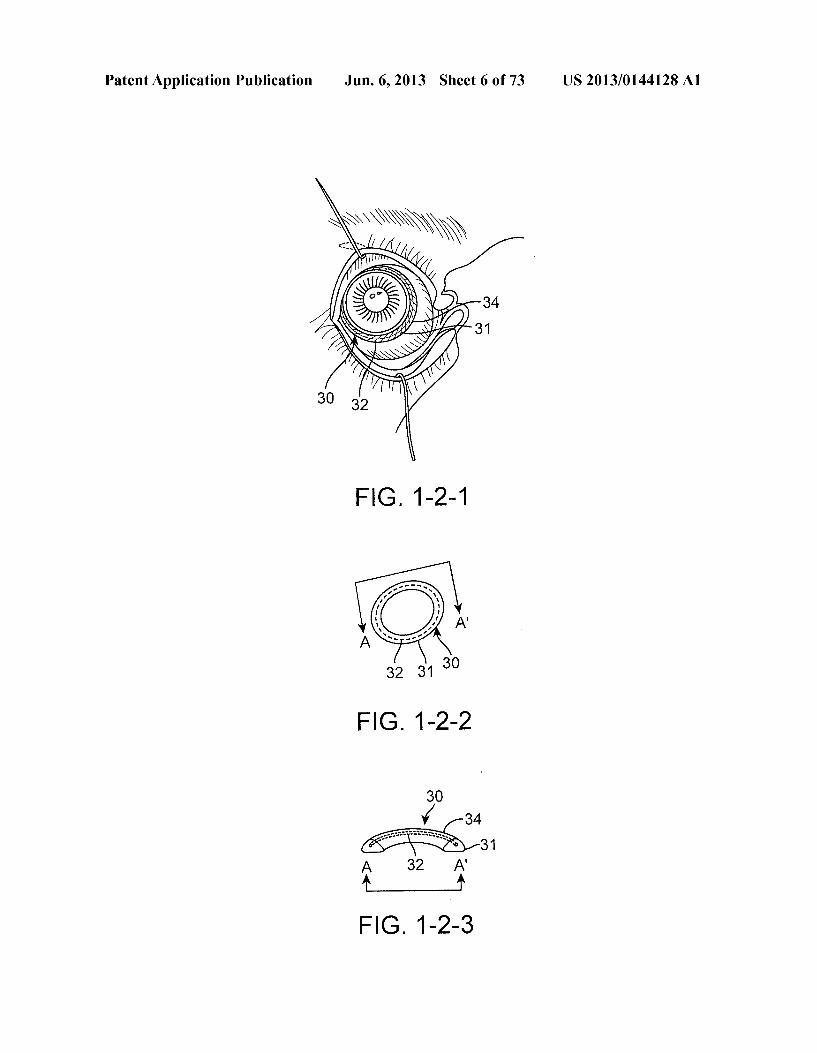
50
58F
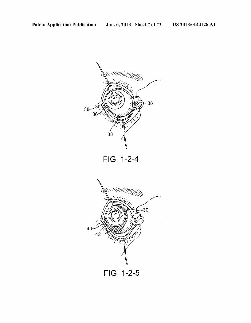
42
58
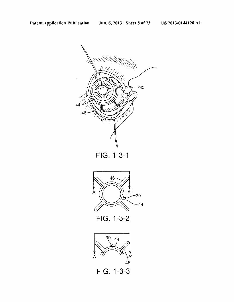
52
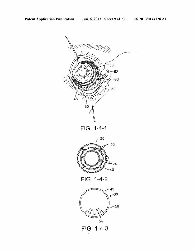
FIG. 1C
Patent Application Publication Jun. 6, 2013 Sheet 3 of 73 US 2013/0144128A1
FIG 1D
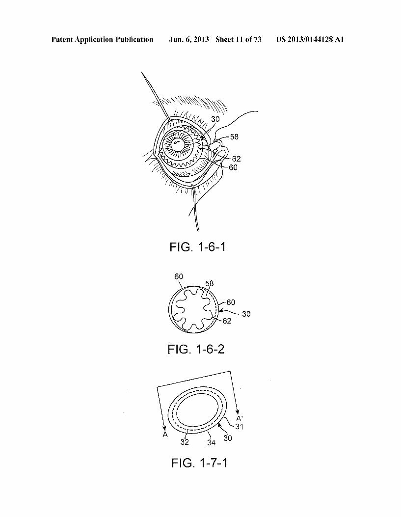
Patent Application Publication Jun. 6, 2013 Sheet 4 of 73 US 2013/014.4128A1
Superior rectus Superior rectus
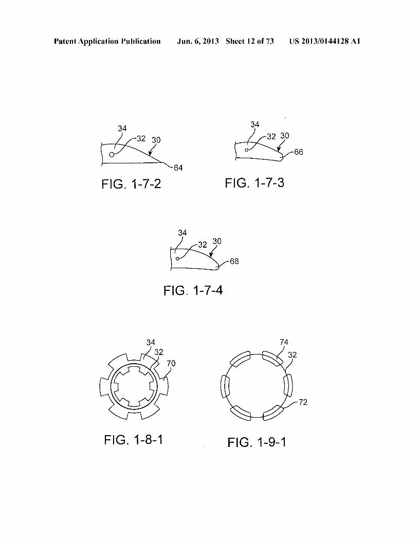
Superior Superior oblique oblique
Lateral rectuS
Inferior Inferior oblique oblique
Inferior / \ Inferior rectuS rectuS
N-2 FIG 1E
Patent Application Publication Jun. 6, 2013 Sheet 5 of 73 US 2013/014.4128A1
FIG 1-1-2
Patent Application Publication Jun. 6, 2013 Sheet 6 of 73 US 2013/014.4128A1
Patent Application Publication Jun. 6, 2013 Sheet 7 of 73 US 2013/014.4128A1
FIG 1-2-5
Patent Application Publication Jun. 6, 2013 Sheet 8 of 73 US 2013/014.4128A1
F.G. 1-3-3
Patent Application Publication Jun. 6, 2013 Sheet 9 of 73 US 2013/014.4128A1

Patent Application Publication Jun. 6, 2013 Sheet 10 of 73 US 2013/014.4128A1
FIG 1-5-2
30
56
FIG 1-5-3
Patent Application Publication Jun. 6, 2013 Sheet 11 of 73 US 2013/014.4128A1
F.G. 1-6-1
FIG. 1-7-1
Patent Application Publication Jun. 6, 2013 Sheet 12 of 73 US 2013/014.4128A1
34 34
66
64
FIG. 1-7-2 FIG. 1-7-3
34
32 30 68
FIG 1-7-4
34 74 32 32
70
72
FIG 1-8-1 FIG. 1-9-1
Patent Application Publication Jun. 6, 2013 Sheet 13 of 73 US 2013/014.4128A1
114A
11 O
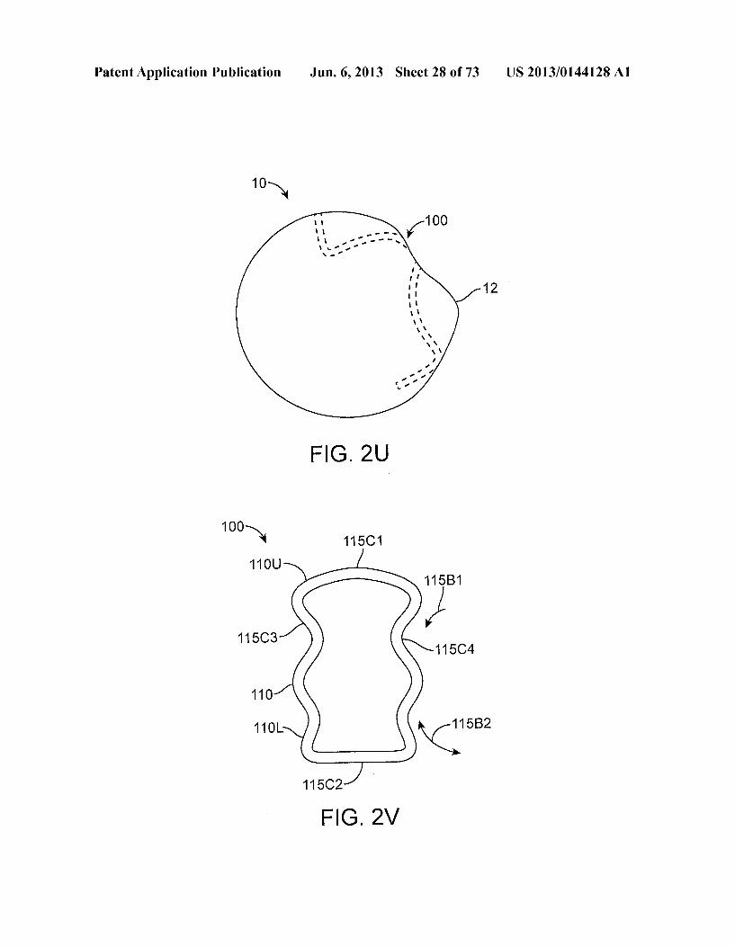
- K?" O
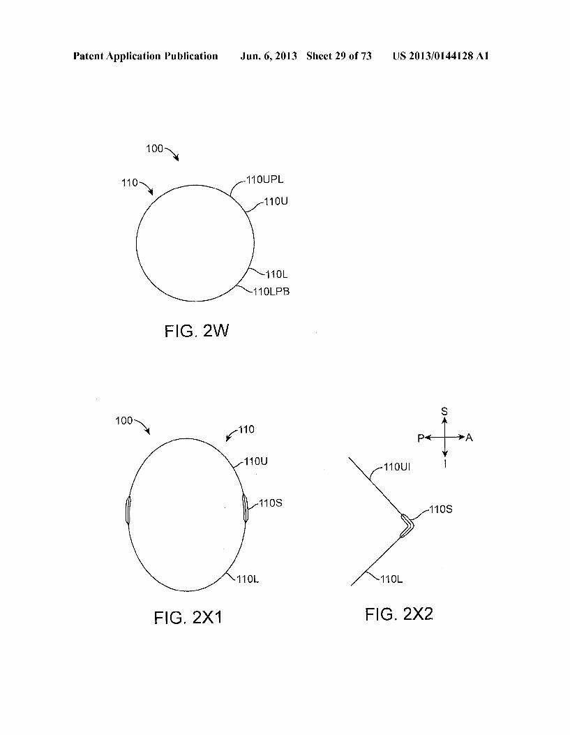
FIG. 2B
114C
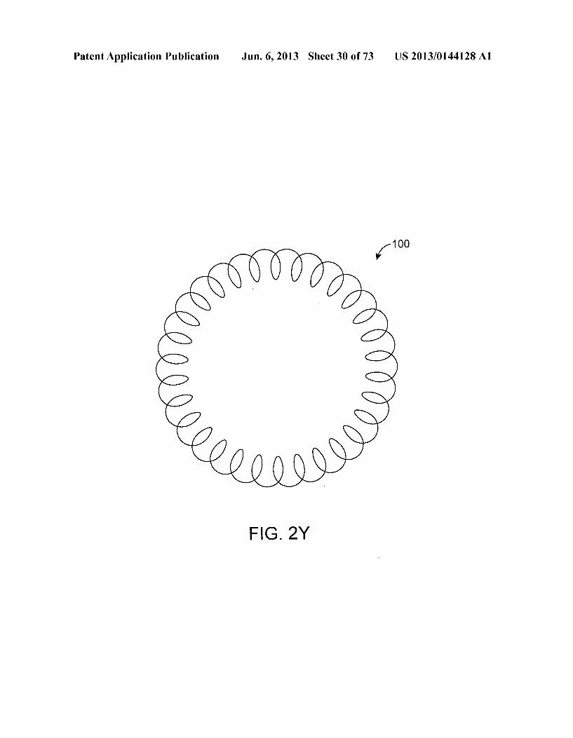
11 4D K—? -100
110
114B
(S2 FIG. 2C
Patent Application Publication Jun. 6, 2013 Sheet 14 of 73 US 2013/014.4128A1
110 11 OU Y Y 11 OSLA
11OL
FIG. 2C1
y 11 OL
110UN ?
110T-f W 11 OTA
FIG. 2C2
Patent Application Publication Jun. 6, 2013 Sheet 15 of 73 US 2013/014.4128A1
114A2
Patent Application Publication Jun. 6, 2013 Sheet 16 of 73 US 2013/014.4128A1
114S2
Patent Application Publication Jun. 6, 2013 Sheet 17 of 73 US 2013/0144128A1
Patent Application Publication Jun. 6, 2013 Sheet 18 of 73 US 2013/014.4128A1
115C1 110S 110
115C1 11 OH
11 OH FIG. 2M
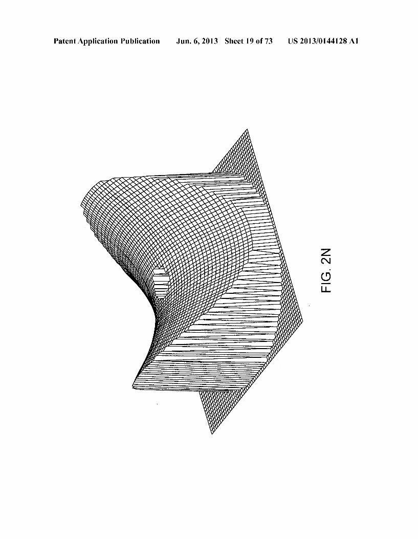
US 2013/0144128A1 Jun. 6, 2013 Sheet 19 of 73 Patent Application Publication
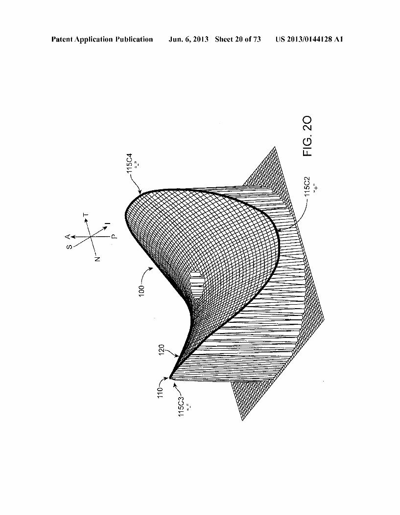
US 2013/0144128A1 Jun. 6, 2013 Sheet 20 of 73 Patent Application Publication
Patent Application Publication Jun. 6, 2013 Sheet 21 of 73 US 2013/014.4128A1
1104
100- 11 OD1
11 OD2
110L FIG. 2P1
S
1104 42
100- A P 18
11 OB1 11 OB2 16
N-10 44
11 OL FG. 2P2
S 1OO N A P
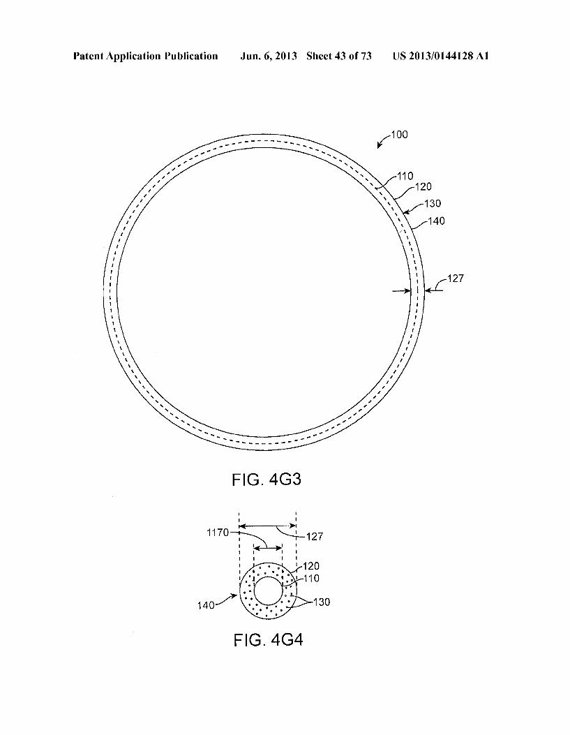
()(Q 11 OH1 11 OH2
FIG. 2P3
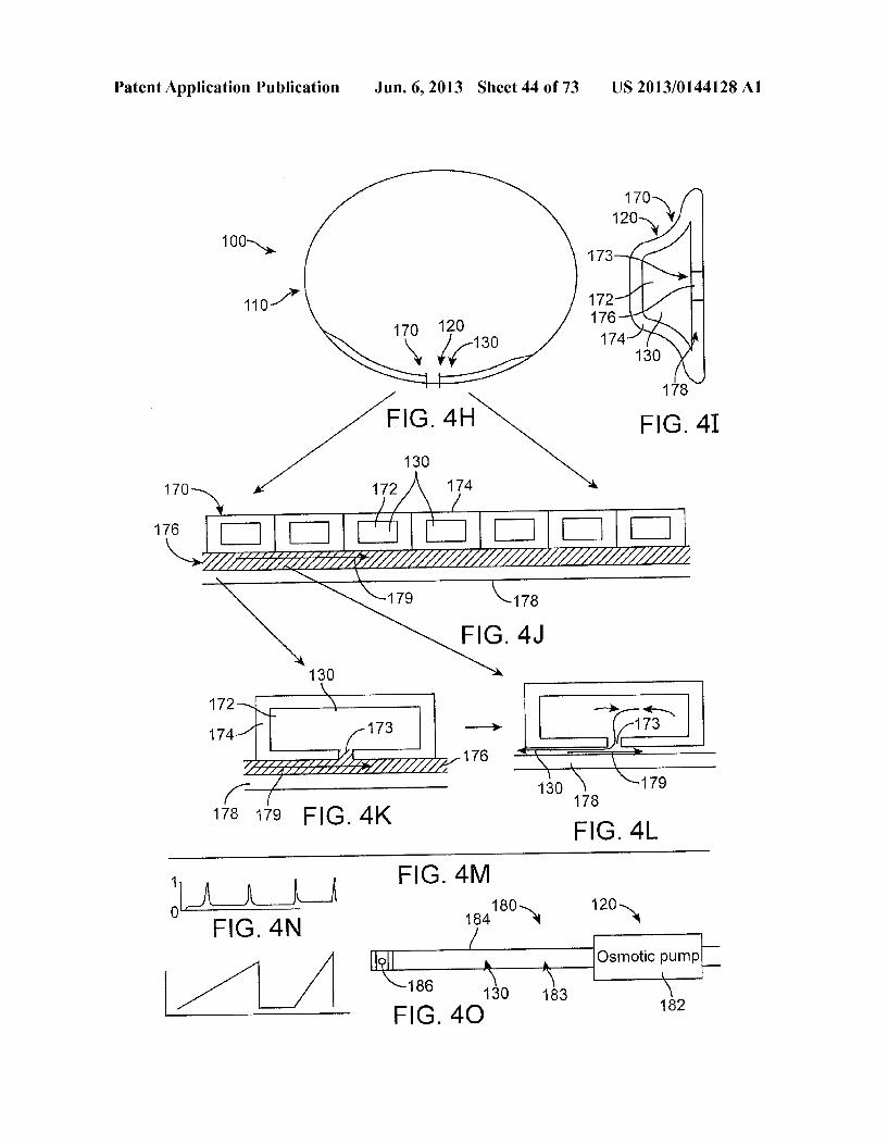
Patent Application Publication Jun. 6, 2013 Sheet 22 of 73 US 2013/014.4128A1
100-N S T
A P
N
115C3
11 OL
115C2
1OO S N T
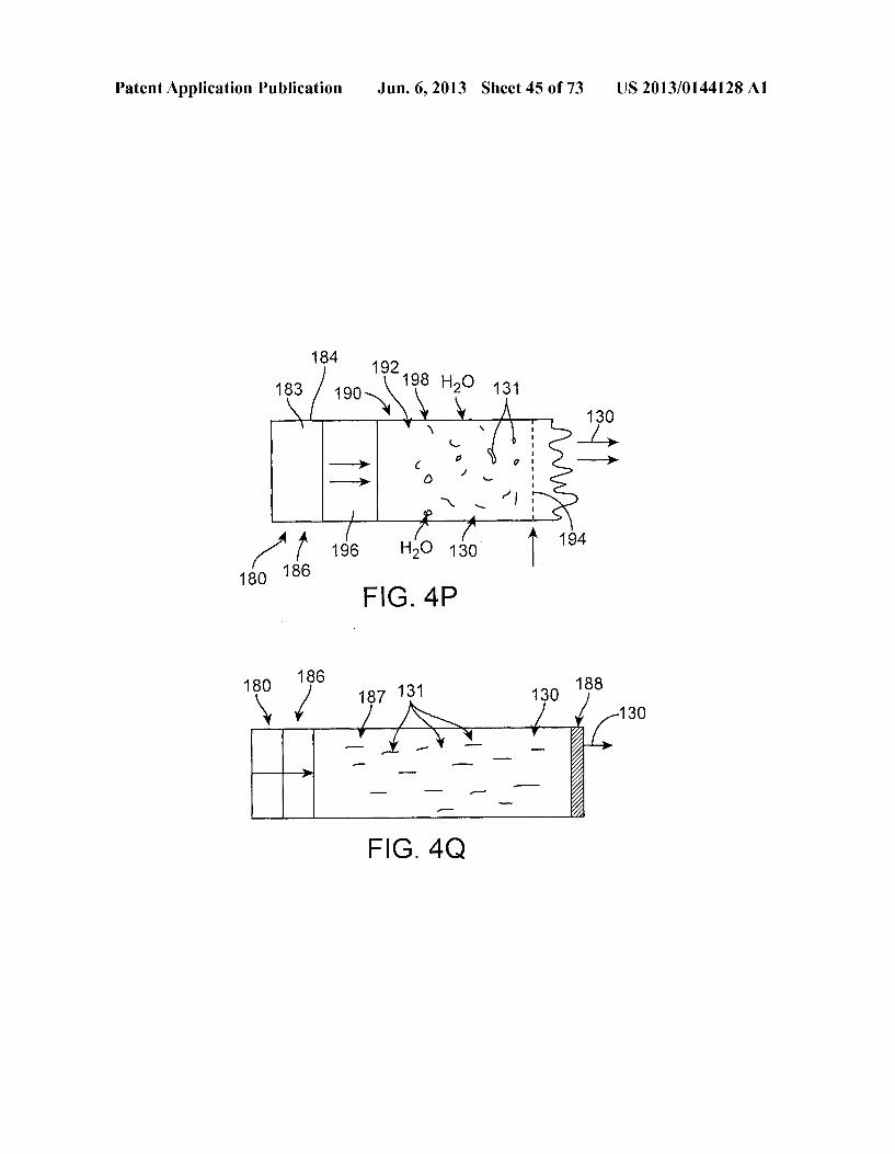
115C1 A P
N
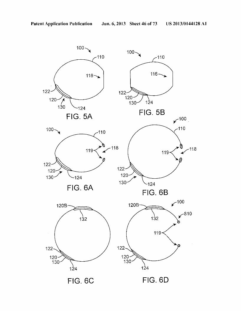
115C4
115C2
FG. 2P5
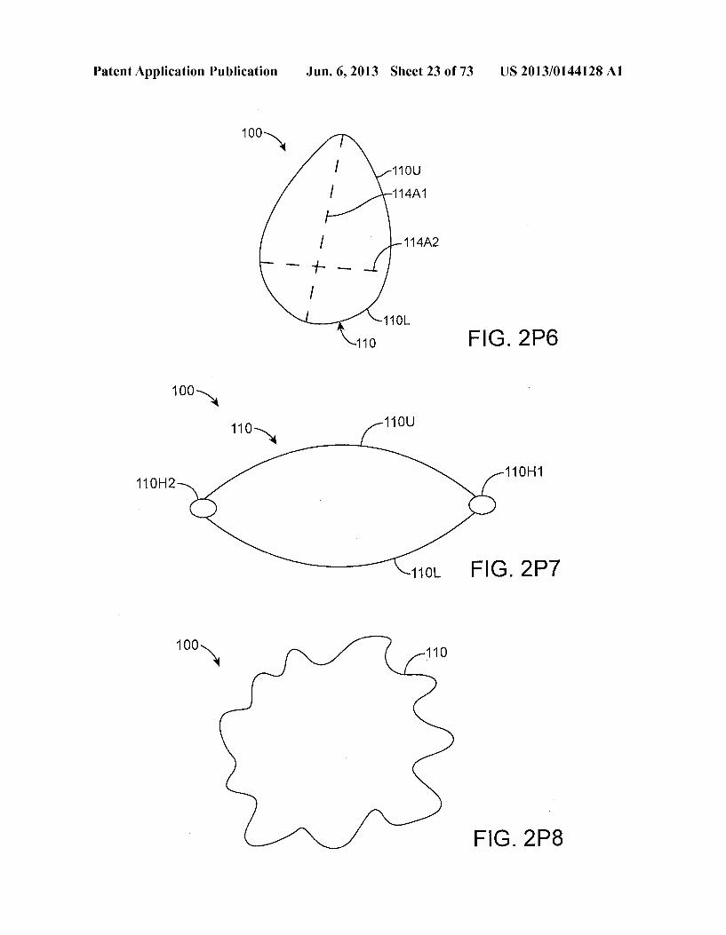
Patent Application Publication Jun. 6, 2013 Sheet 23 of 73 US 2013/014.4128A1
1 OO N 11 OU
114A1
114A2
11 OL
110 FIG. 2P6
11 OH1 11 OH2
FIG. 2P7
100- 110
FG. 2P8
Patent Application Publication Jun. 6, 2013 Sheet 24 of 73 US 2013/0144128A1
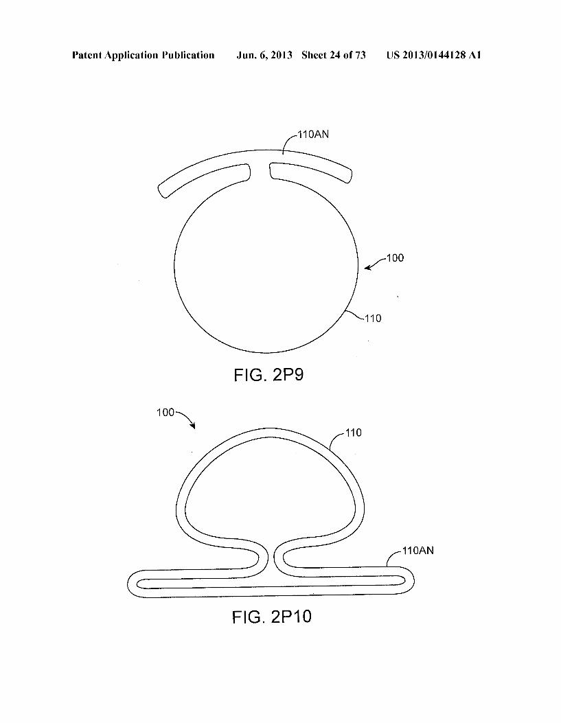
11 OAN
100 41
110
FIG. 2P9
1 OO N 110
11 OAN
FIG. 2P10
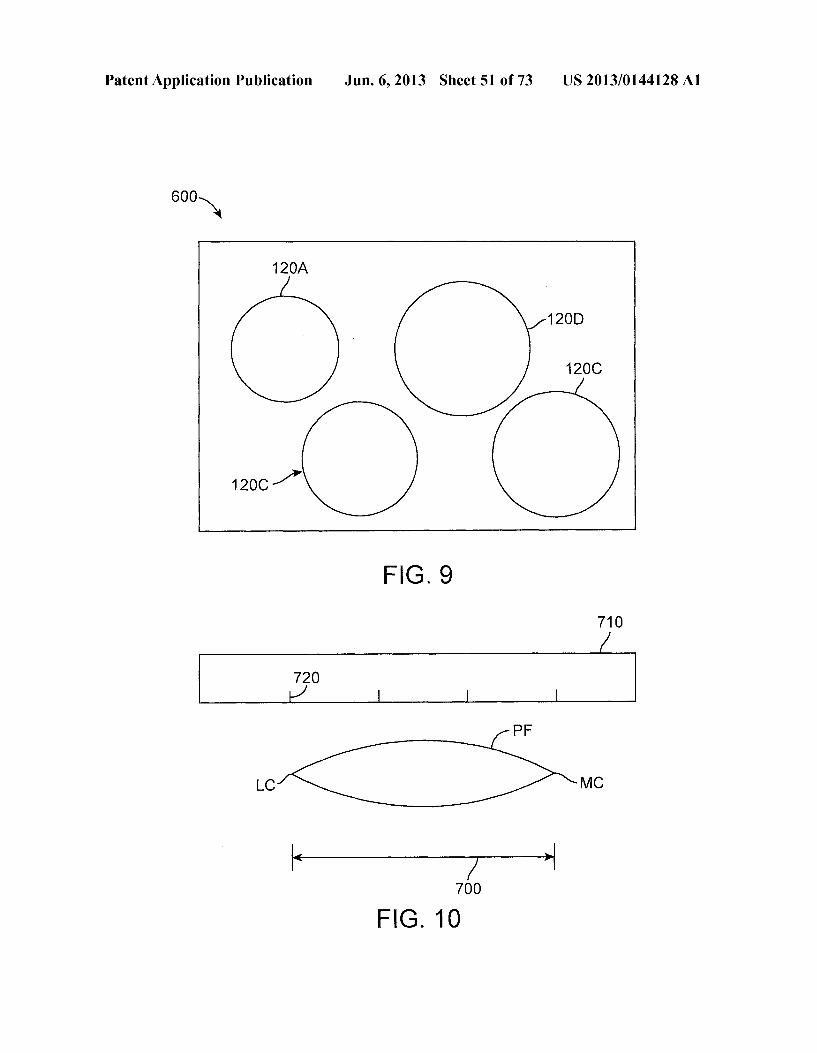
Patent Application Publication Jun. 6, 2013 Sheet 25 of 73 US 2013/014.4128A1
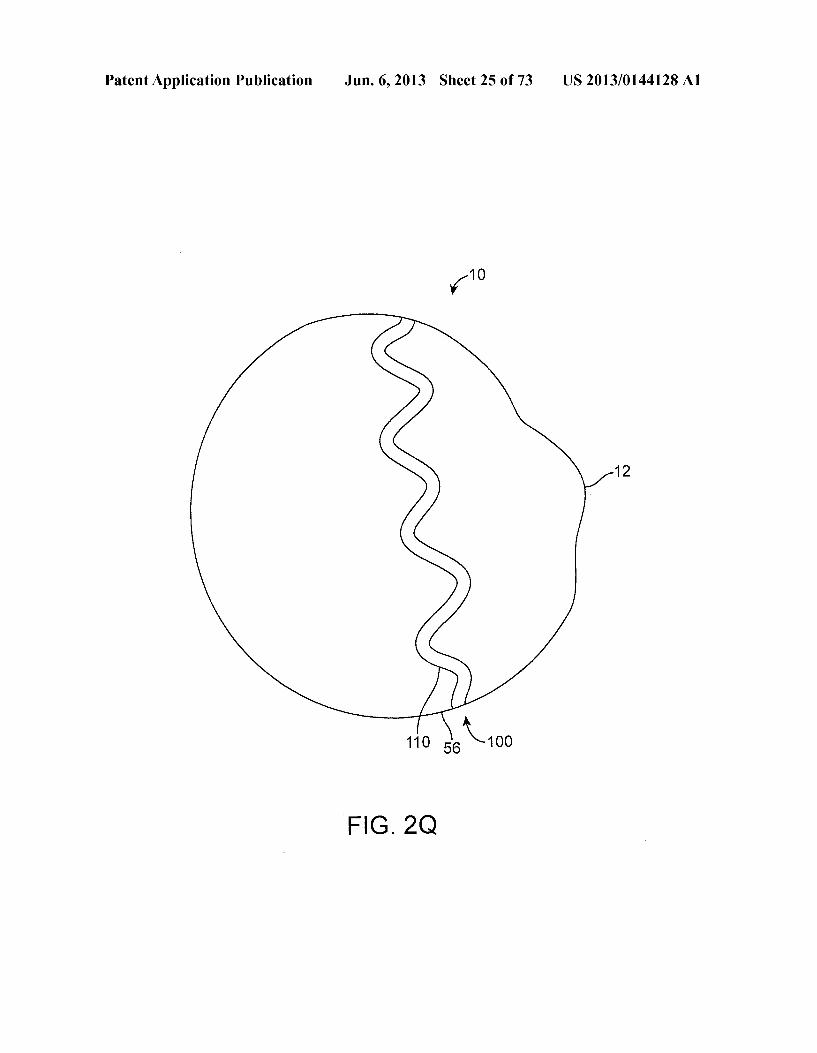
-10
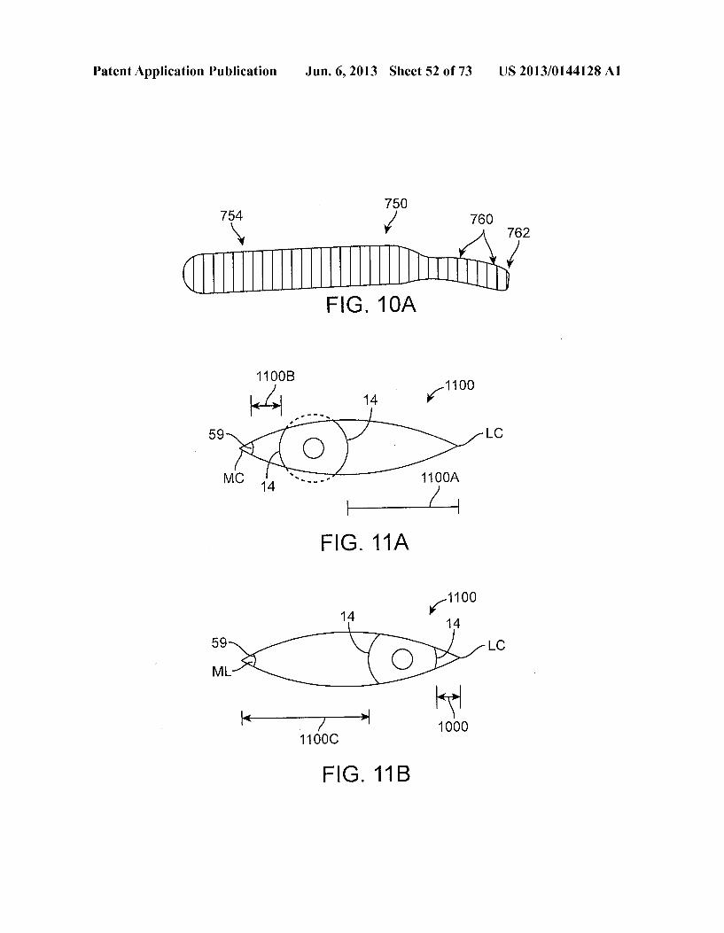
12
110 A too
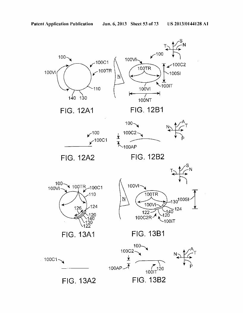
FIG 2G
Patent Application Publication Jun. 6, 2013 Sheet 26 of 73 US 2013/014.4128A1
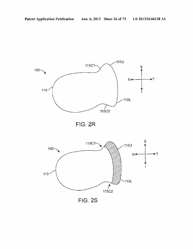
11 OU 115C1 S
100-N N T
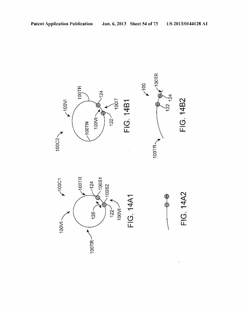
110
11 OL
115C2
11 O
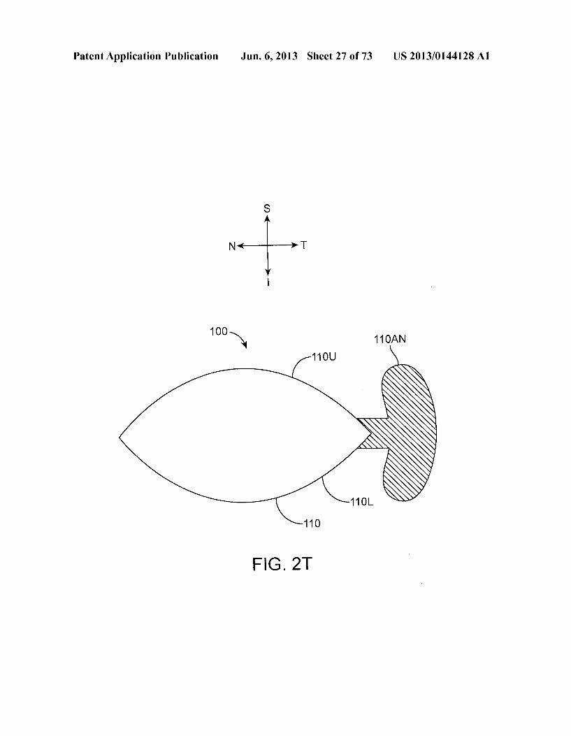
Patent Application Publication Jun. 6, 2013 Sheet 27 of 73 US 2013/014.4128A1
Patent Application Publication Jun. 6, 2013 Sheet 28 of 73 US 2013/014.4128A1
1 OO N 115C1 11 OU
115C3 115C4
110
11 OL ce
115C2
FIG 2V
Patent Application Publication
100 N. 110 11 OUPL
N 11 OU
11 OL
11 OLPB
FIG 2W
1 OO N -110
11 OU
11 OS
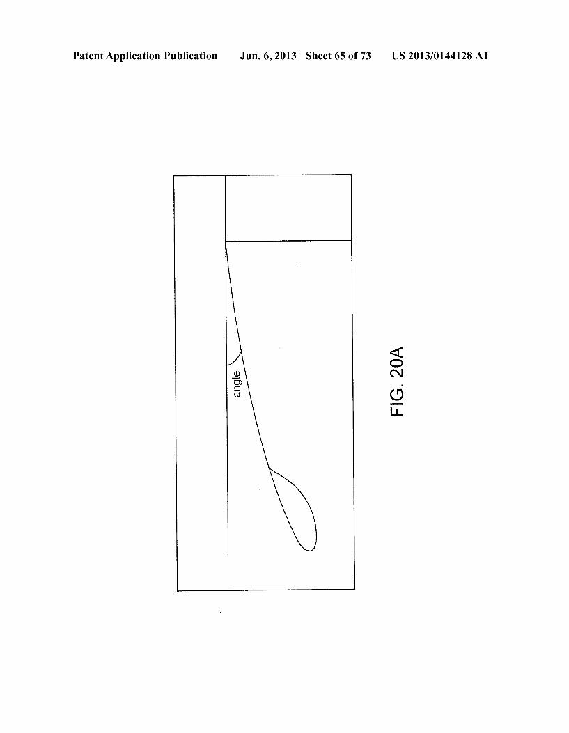
11 OL
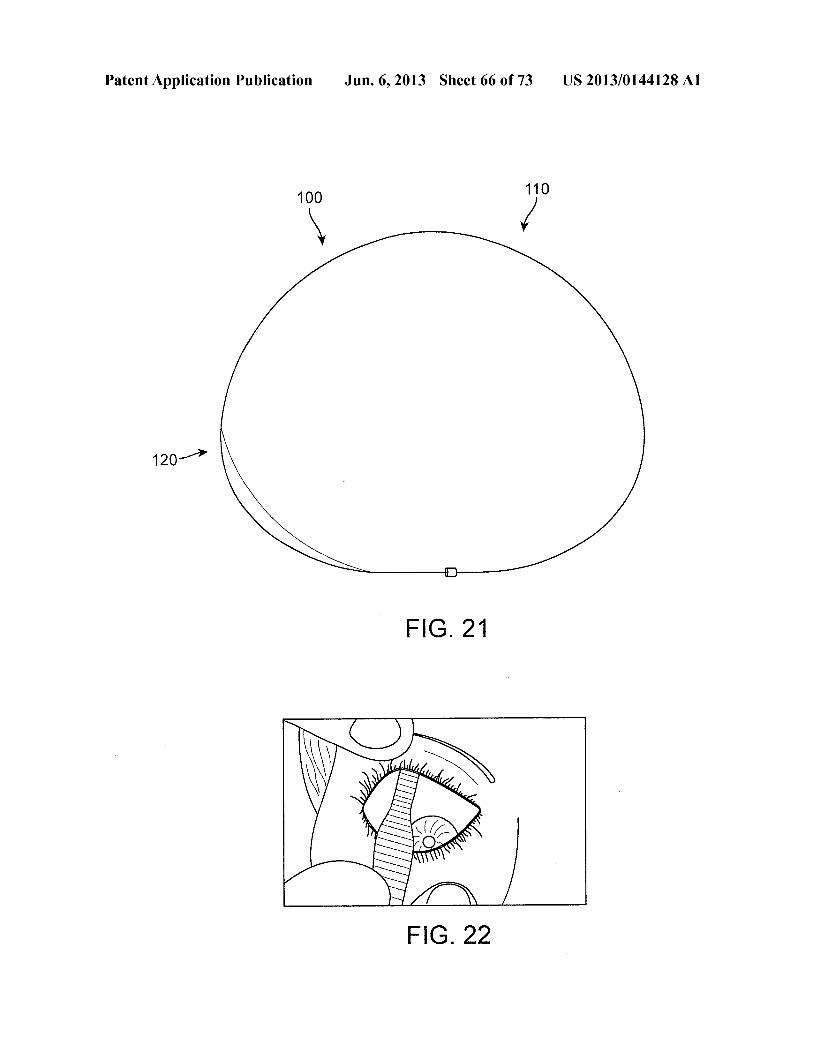
FIG 2X1
Jun. 6, 2013 Sheet 29 of 73 US 2013/014.4128A1
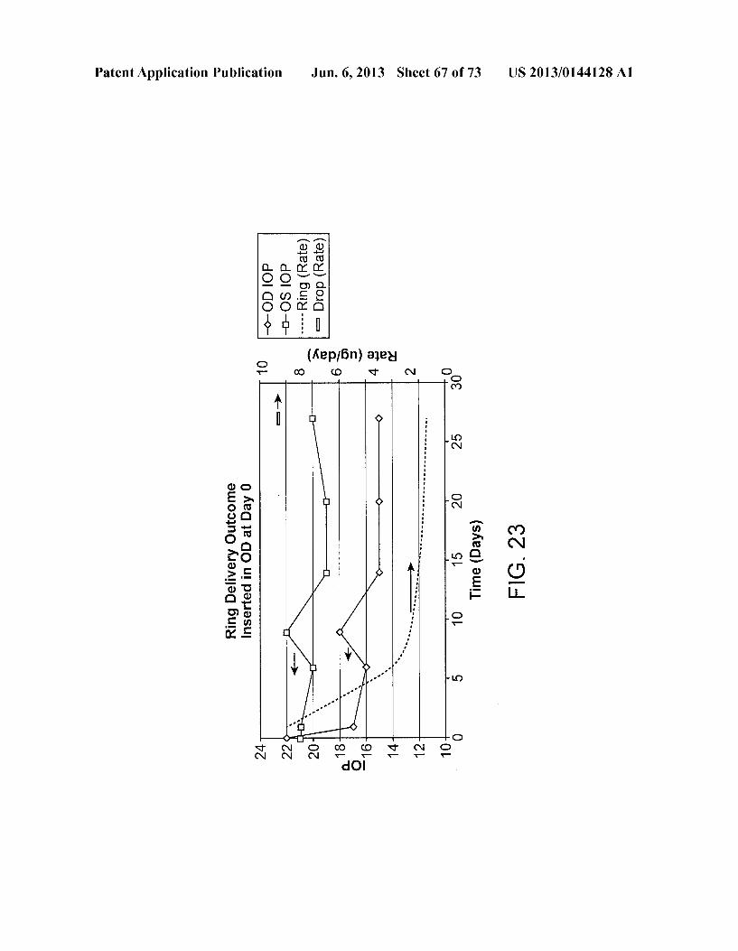
11 OS
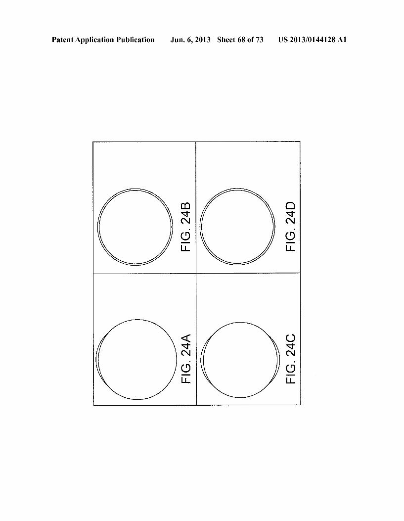
11 OL
FIG 2X2
Patent Application Publication Jun. 6, 2013 Sheet 30 of 73 US 2013/014.4128A1
Patent Application Publication Jun. 6, 2013 Sheet 31 of 73 US 2013/014.4128A1
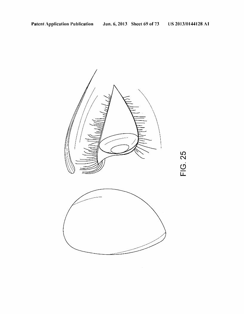
100 Y
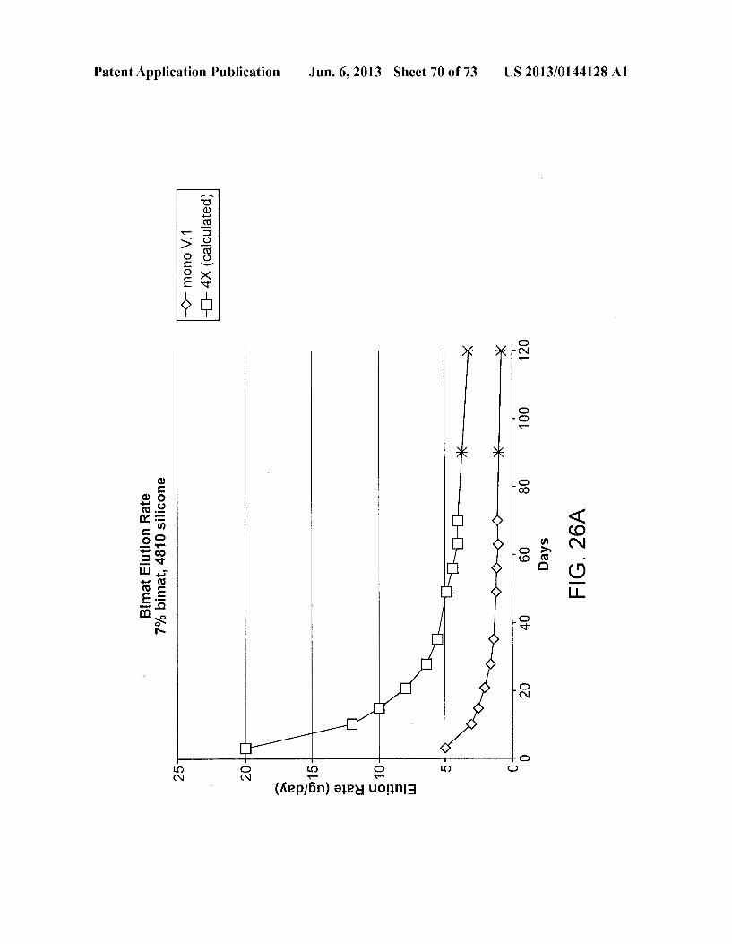
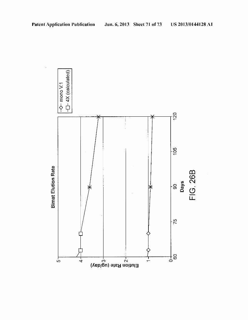
11 O 11 OU
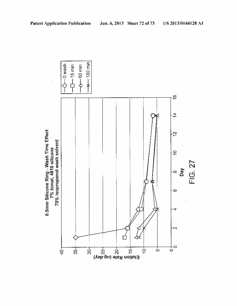
11 OU
11OJ
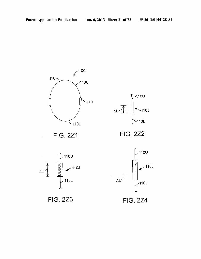
Al- |-ro 11 OL Iro.
FIG 2Z1 FG. 2Z2
11 OU 11 OU
al -110J -110J 11 OL A1 11 OL
FG, 2Z3 FIG. 2Z4
Patent Application Publication Jun. 6, 2013 Sheet 32 of 73
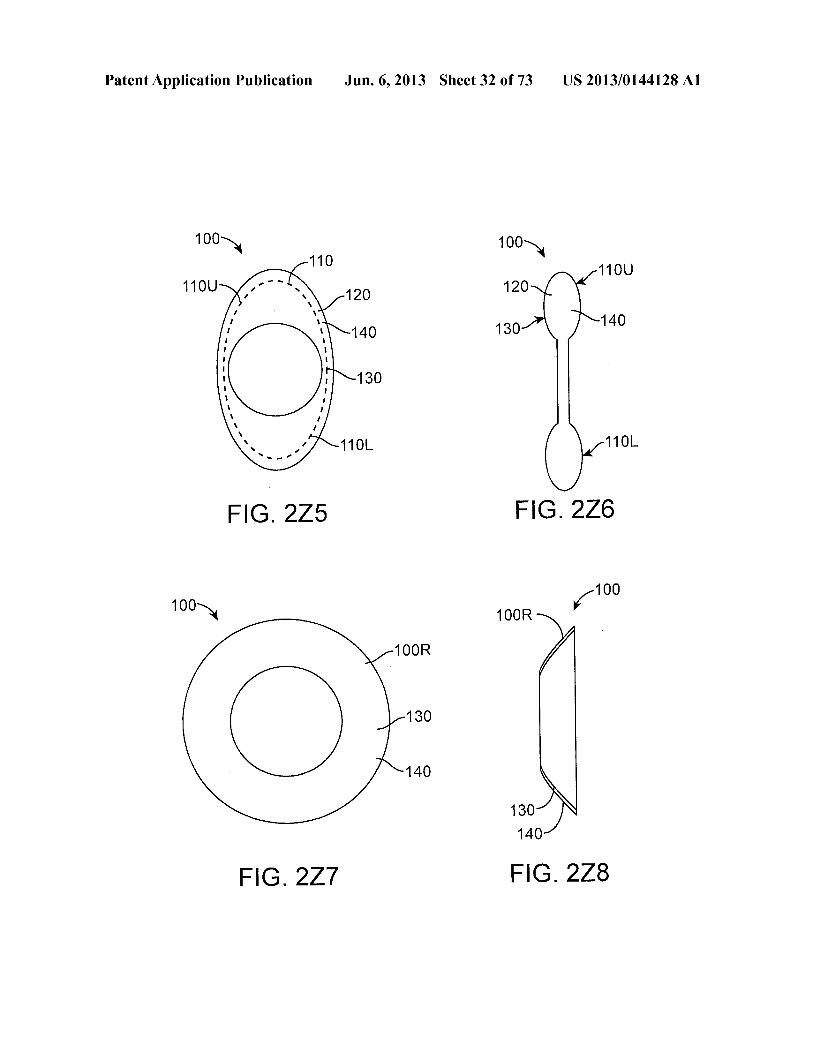
FIG 2Z7
1OOR
130
140
11 OL
FIG. 276
100 Y 1 OOR
130 N 140
FIG 2Z8
US 2013/014.4128A1
Patent Application Publication Jun. 6, 2013 Sheet 33 of 73 US 2013/014.4128A1
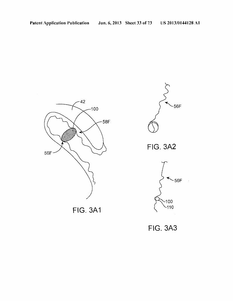
FIG 3A2
100
FIG 3A1 ro
FG. 3A3
Patent Application Publication Jun. 6, 2013 Sheet 34 of 73 US 2013/014.4128A1
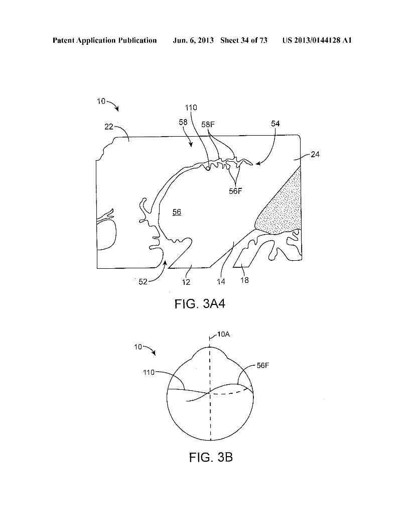
10-N 110
t 12 14 18
FIG 3A4
-10A 10N
56F
11 O Q
FIG. 3B
Patent Application Publication Jun. 6, 2013 Sheet 35 of 73 US 2013/014.4128A1
4OM
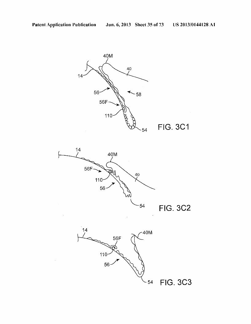
FIG. 3C 1
14 40M 56F
110
54 FIG. 3C3
Patent Application Publication Jun. 6, 2013 Sheet 36 of 73 US 2013/014.4128A1
Patent Application Publication Jun. 6, 2013 Sheet 37 of 73 US 2013/014.4128A1
f 100 T
Patent Application Publication Jun. 6, 2013 Sheet 38 of 73 US 2013/014.4128A1
100- 120 100-N 110
(2S 110
T N T 2. N
FIG. 3H " FG, 3G 100
100-N - 162 y e-N
11 O , 110
T N
120 164
FG, 3.I 130 100
100- 113 -> K? ?
-> K-164
Q-1 r. 110 110 FIG 3J-1
100 FIG 3K N -170
110 -140 17O
172
Stz 140 130
FIG. 3L FIG 3L-1
Patent Application Publication Jun. 6, 2013 Sheet 39 of 73 US 2013/014.4128A1
53 42 N 42
58 130 52
6& 130 56
XXXXX
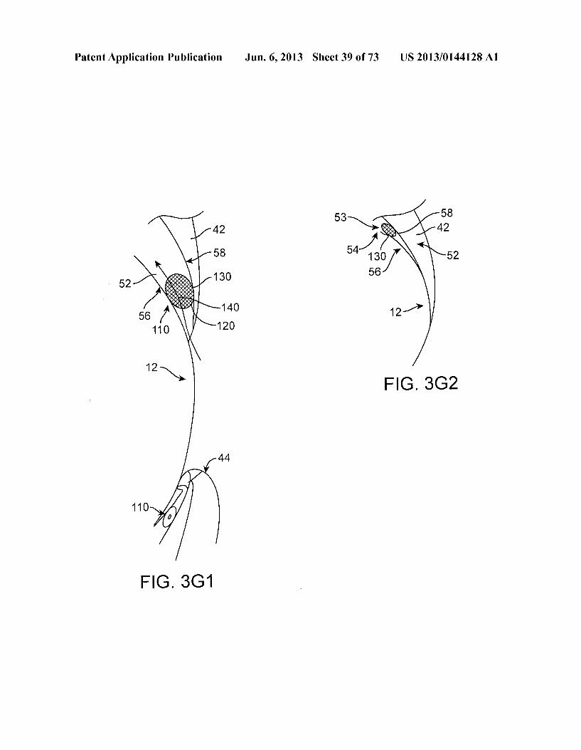
&T ) 140 12-1 120
FG, 3G2
Patent Application Publication Jun. 6, 2013 Sheet 40 of 73 US 2013/014.4128A1
130
11 O
130 110 110 A-1
126
FIG 4E
Patent Application Publication Jun. 6, 2013 Sheet 41 of 73 US 2013/014.4128A1
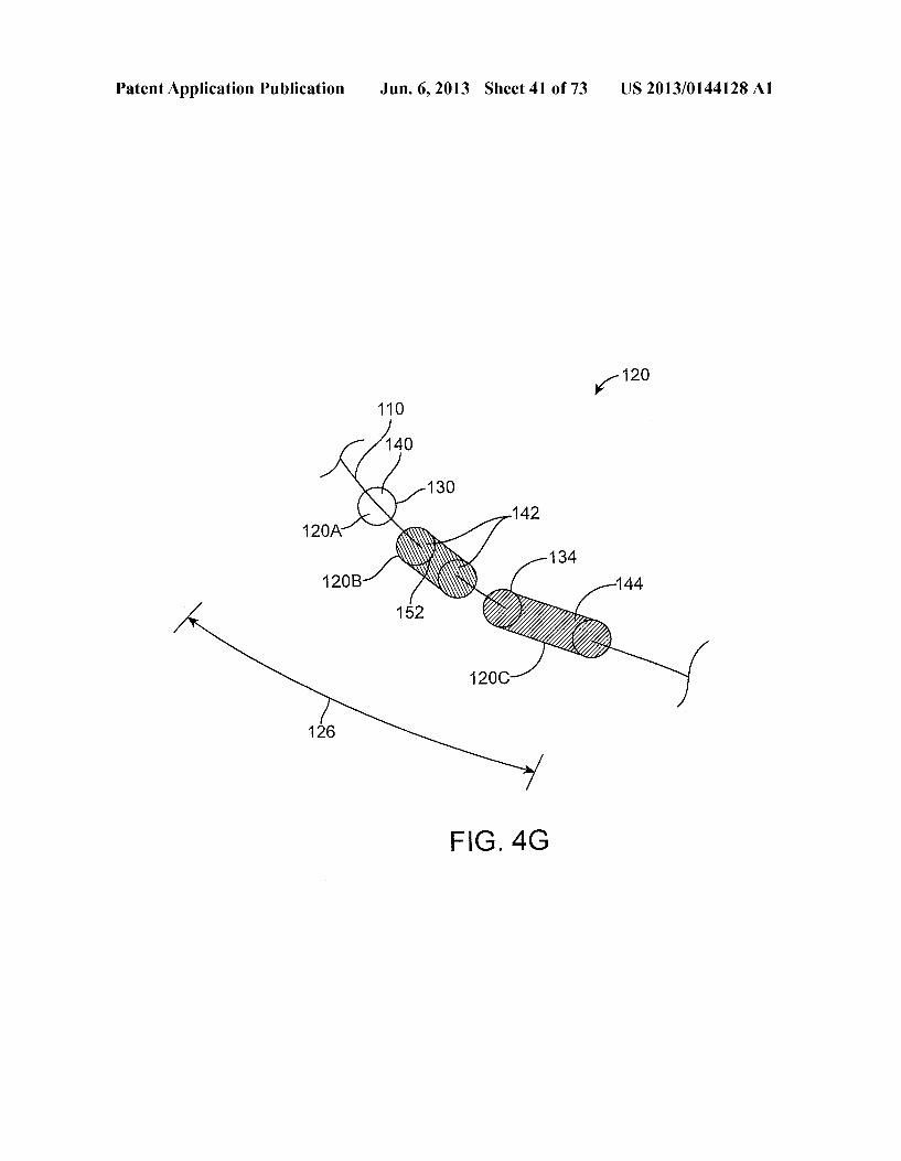
120 y
FG, 4G
Patent Application Publication Jun. 6, 2013 Sheet 42 of 73 US 2013/014.4128A1
Patent Application Publication Jun. 6, 2013 Sheet 43 of 73 US 2013/014.4128A1
Patent Application Publication Jun. 6, 2013 Sheet 44 of 73 US 2013/0144128A1
100-N 173 N
110-1 172 176
NY 2 174 130 178
FIG 4H FIG. 4I
170
2
172-N Y "it "l Z2422-176 SC / 130 -179
178 179 FIG. 4K FIG. 4L
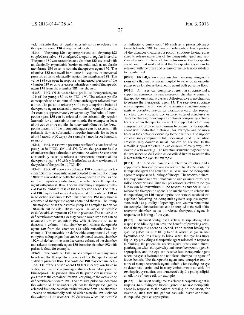
1 FIG. 4M
IJ J – 180- 120 FIG 4N
IL. A osmote pump 184
186 130 183 2 FIG. 4O 18
Patent Application Publication Jun. 6, 2013 Sheet 45 of 73 US 2013/014.4128A1
Patent Application Publication Jun. 6, 2013 Sheet 46 of 73 US 2013/014.4128A1
100 N. 110
122 N 120
130 124
FIG 5A
100- 110
risk 122 122 120
130 / N24 120 130
FIG 6A
12OB
122 122
120 120 130 130
124 124
F.G. 6C FIG. 6D
Patent Application Publication Jun. 6, 2013 Sheet 47 of 73 US 2013/014.4128A1
7 N 11 O
116 T 11 N T N
110
F.G. 5I FIG 5J
Patent Application Publication Jun. 6, 2013 Sheet 48 of 73 US 2013/0144128A1
Patent Application Publication Jun. 6, 2013 Sheet 49 of 73 US 2013/0144128A1
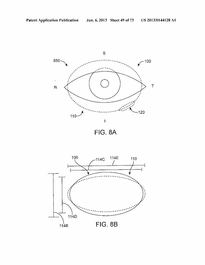
1OO 114C 114E 110
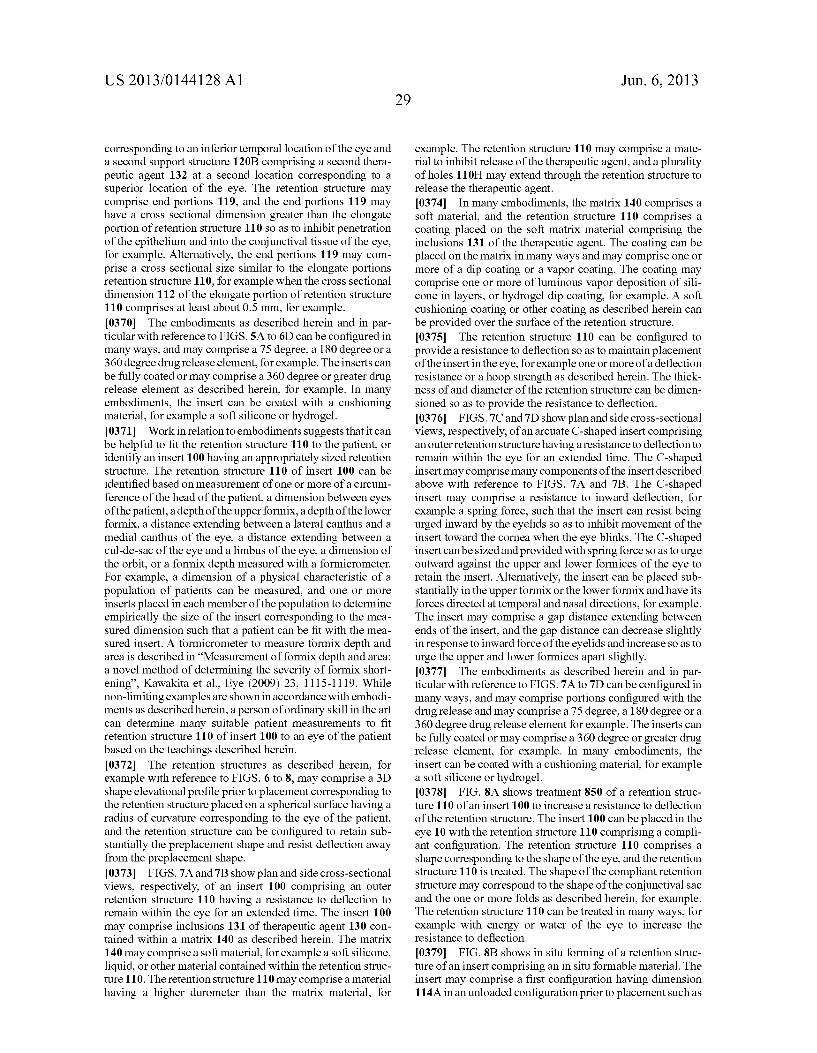
114B FIG. 8B
Patent Application Publication Jun. 6, 2013 Sheet 50 of 73 US 2013/014.4128A1
322
Patent Application Publication Jun. 6, 2013 Sheet 51 of 73 US 2013/014.4128A1
600 N
FIG 9
710
720
PF
700
FIG 10
Patent Application Publication Jun. 6, 2013 Sheet 52 of 73 US 2013/014.4128A1
754 750
N y 760 y
FIG 1 OA
1100
11 OOC
FIG 11B
Patent Application Publication Jun. 6, 2013 Sheet 53 of 73 US 2013/014.4128A1
S T N
100 100- 1OOC1 100V
1. -100C2 1OOV -100TR 1 OOS
N 110 ov, S100T 140 130 1OONT
F.G. 12A1 FIG. 12B1
122 100C2R1
F.G. 1 3B1 1 OO N A
to- N T 100C1 N. - \s
100AP- 106.20 P
US 2013/014.4128A1 Jun. 6, 2013 Sheet 54 of 73 Patent Application Publication
Patent Application Publication Jun. 6, 2013 Sheet 55 of 73 US 2013/014.4128A1
100-N 11 O
1OOTR
1OOV (Z) 1<
(2 124 122
130 132
N-110 140 142
F.G. 16B

Patent Application Publication Jun. 6, 2013 Sheet 56 of 73 US 2013/014.4128A1
100N 110 100-N 110 130
140
120 130
FIG. 16C
110
Patent Application Publication Jun. 6, 2013 Sheet 57 of 73 US 2013/0144128A1
1700
1712 SY 1722
C 1714 CS 1724 1710 1720
FIG. 17A
FIG. 17B
Patent Application Publication Jun. 6, 2013 Sheet 58 of 73 US 2013/0144128A1
11712BC
1712AC
F.G. 17C
1712AC
12OS3
1712CC
F.G. 17D
Patent Application Publication Jun. 6, 2013 Sheet 59 of 73 US 2013/014.4128A1
1710
FIG. 17E
1720
120 1714 R.
1710
FIG 17F
Patent Application Publication Jun. 6, 2013 Sheet 60 of 73 US 2013/014.4128A1
1712BC
1712AC
1710 1712CC
Patent Application Publication
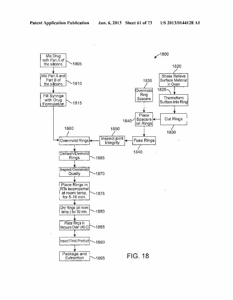
Mix Drug With Part A of the silicone 1805
Mix Part A and Part B of
the Silicone 1810
Fill Syringe with Drug Formulation 1815
1860
Ovenmold Rings
Dellash/Demold Rings
Inspect Ovenmold Quality
Place Rings in RTs isoproponal at room temp. for 5-10 min.
Dry Rings (atroom temp.) for 30 min.
Place Rings in Vacuum Oven (40C)
Package and Extraction
Insert Final Product
Jun. 6, 2013 Sheet 61 of 73
1840
1850
Inspect joint Integrity
1865
1870
1875
1880
1885
1890
1895
US 2013/014.4128A1
1800 1.
Oven mold Ring
Spacers
Place Spacers on Rings
1845
FIG. 18
1820
Stress Relieve Surface Material
in Owen 1825
Thermoform Surface into Ring
1830

Patent Application Publication Jun. 6, 2013 Sheet 62 of 73 US 2013/014.4128A1
FIG. 18A
110
SS 59 ( )
FG 18B
Patent Application Publication Jun. 6, 2013 Sheet 63 of 73 US 2013/014.4128A1
Patent Application Publication Jun. 6, 2013 Sheet 64 of 73 US 2013/014.4128A1
12O
2S 110
T nasal N T
110 St 120
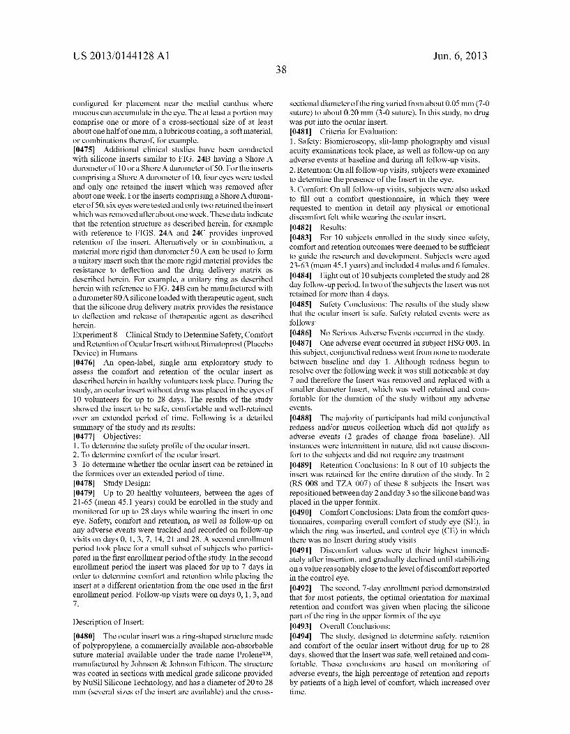
F.G. 19A FIG. 19E
110
C." N St N T
120 S.
FIG. 19B 110
F.G. 19F
C. is 2 120 OR
FIG. 19C 120
2 is T N
F.G. 19D
Patent Application Publication Jun. 6, 2013 Sheet 65 of 73 US 2013/0144128A1
Patent Application Publication Jun. 6, 2013 Sheet 66 of 73 US 2013/014.4128A1
1 O 100 1
US 2013/014.4128A1 Jun. 6, 2013 Sheet 67 of 73 Patent Application Publication
CHO|| ClO–O–
Patent Application Publication Jun. 6, 2013 Sheet 68 of 73 US 2013/014.4128A1
CC O V N CN CN
CD O - -
Patent Application Publication Jun. 6, 2013 Sheet 69 of 73 US 2013/014.4128A1
Patent Application Publication Jun. 6, 2013 Sheet 70 of 73 US 2013/014.4128A1
area
"O C) wim
c
Sl 9 X 8 SF
83s 8 i
.
S.
S
O O O O
(Kepibn) eley uoung S S
Patent Application Publication Jun. 6, 2013 Sheet 71 of 73 US 2013/014.4128A1
s 2 2 {}
3s S. i
US 2013/014.4128A1 Jun. 6, 2013 Sheet 72 of 73
?uÐA?os useM | Ouedoudos! %0,1
Patent Application Publication
O O ld O CN CN wer ver
(Aepfn) ele uon O cy
d cy)
Patent Application Publication Jun. 6, 2013 Sheet 73 of 73 US 2013/014.4128A1
CD w CS Y C .9 ww
2 I
a 3 O a 5 5
(Aepffn) eye
F
US 2013/0144128A1
OCULAR INSERTAPPARATUS AND METHODS
CROSS-REFERENCES TO RELATED APPLICATIONS
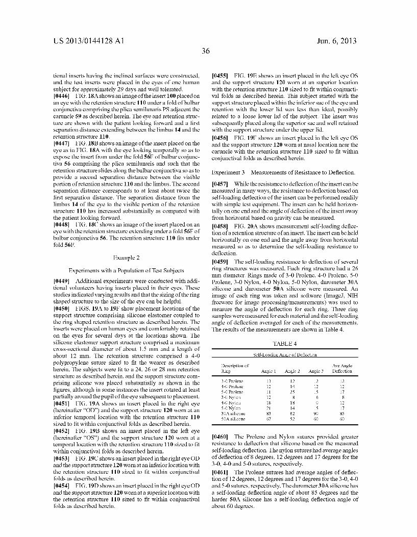
0001. This application claims priority of the following co-pending U.S. Provisional patent applications: (1) U.S. Provisional Application Ser. No. 61/534,845, titled "Ocular Insert Apparatus And Methods.” filed on Sep. 14, 2011; and (2) U.S. Provisional Application Ser. No. 61/568,624, titled "Ocular Insert Apparatus And Methods.” filed on Dec. 8, 2011. The disclosures of the Provisional Patent Applications are hereby incorporated by reference in their entirety. 0002 The subject matter of the present application is related to the following co-assigned patent applications: PCT App. No. PCT/US2010/037268, published as WO2010/ 141729 on Dec. 9, 2010, entitled “Anterior Segment Drug Delivery”; U.S. patent application Ser. No. 13/151,001, filed on Jun. 1, 2010, entitled “Anterior Segment Drug Delivery': and U.S. Prov. Pat. App. Ser. No. 61/534,845, filed on Sep. 14, 2011, entitled "Ocular Insert Apparatus and Methods, the full disclosures of which are incorporated herein by refer CCC.
BACKGROUND
0003 1. Field. 0004. Described herein are structures, systems, and meth ods for placement of an insert on an eye that may be used to treat the eye. Exemplary embodiments provide ocular inserts used for drug delivery, along with methods for using ocular inserts positioned on or near the anterior Surface of the eye. The exemplary inserts may be worn along an anterior Surface of the eye outside the optical Zone, and can deliver therapeu tically efficacious amounts of one or more therapeutic agents. 0005 0006 A variety of ophthalmic and non-ophthalmic condi tions necessitate administration of various drugs to the eye. Eye drops and gels can be effective drug delivery vehicles, but can also have significant disadvantages. Specifically, eye drops mix with fluid in the tear film, but may have a residence time of only 2-5 minutes in the tear film. As little as 5% of the drug may be absorbed locally; some or all of the rest being carried from the lacrimal sac into the lacrimal duct, which can have potentially undesirable effects. Consequently, most of the drug may be wasted with less than ideal amounts delivered to the targeted tissue. Also, the presence of the drug in the bloodstream may have potentially harmful side effects. Gels may adhere more effectively to the eye, but can also blur the patient’s vision. Both eye drops and gels may need to be reapplied frequently for Some therapies, and patients may not administer the eye drops or gels as frequently as directed in at least some instances, such that the amount of drug delivered can be less than ideal. For example, in at least Some instances a Substantial number of patients may not refill their prescrip tion after one year, and the Substantial number of patients can be up to fifty percent in some instances. Thus, a need remains for improved drug delivery to the eye having less frequent user application and providing improved regularity of the amount of drug delivered to the eye. Another potential disad Vantage of topically applied drops and gels can be that Such bolus dosing may result in hyperemia and irritation of ocular tissue in at least some instances.
2. Background.
Jun. 6, 2013
0007 Inlight of the disadvantages of eye drops, it is under standable that a variety of alternatives have been proposed. Among the known prior alternatives to drops include treat ments in which insert structures containing or impregnated with drugs have been placed under an eyelid, in a punctum, or on the cornea with drug-impregnated contact lenses, and the like.
0008 Although such prior insert structures appear to present significant potential advantages over drop-adminis tered drug treatment of the eye, the prior approaches with insert structures can provide less than ideal results in at least Some instances. Although intravitreal and intraocular implants have been proposed, Such implants can be more invasive that would be ideal in at least some instances. While punctual plugs can be less invasive, the amount of therapeutic agent available for Sustained release can be less than ideal in at least Some instances. The clinical acceptance of the prior insert structures has been less than ideal, and many drugs continue to be delivered to the front of the eye with drops. Clinical studies with prior insert structures appear to have shown that in at least some instances the priorinsert structures may not work as well as would be ideal for at least some patients of a patient population. Factors that may have con tributed to the limited acceptance of prior ocular inserts include: a lack of efficacy, a lack of comfort, propensity for displacement or movement from a desired position on the eye, incidents of inadvertent expulsion during sleep or rubbing of the eye, interference with vision, and difficulty with place ment and removal. For example, in at least some instances the prior insert structures may not be retained in the eye as long as would be ideal, resulting in less than ideal amounts of the drug delivered to the eye. In at least some instances, the force of the eyelids, eye movement, change in insert position, or eye rub bing may not keep the prior inserts in the eye and the force of the eyelid may expel the insert from the eye. The prior insert devices can be less comfortable than would be ideal, and in at least Some instances blinking of the eye may cause the insert to touch the cornea, or rub against the palpebral or bulbar conjunctiva, resulting in discomfort for the patient in at least Some instances. Further, assuming the prior insert structure can be retained in the eye for the extended time, the amount of drug released and the release rate profile of the amount released for the extended time can be less than ideal for at least some of the prior insert structures in at least some instances.
0009. In light of the above, new drug delivery devices, systems, and methods would be beneficial, particularly for delivering therapeutic agents to the anterior segment of the eye. It would be particularly advantageous to provide improved ocular inserts which are configured as to gain greater acceptance from both physicians and users, with Such inserts ideally being easier to insert and remove, providing greater retention and compliance with a population of patients, providing greater patient comfort while remaining on the eye for an extended time, being non-toxic and not interfering with vision, and the like. It would also be desirable to provide improved ocular inserts which would provide improved amounts of release, release profiles and pharmaco kinetics throughout long term use, including providing safe, efficient and reproducible local therapeutic agent release from the device with limited systemic or localized side effects and effective transportation to and absorption by tissues that provide therapeutic benefits, ideally while being relatively easy to manufacture at a reasonable price.
US 2013/0144128A1
SUMMARY
00.10 Embodiments are generally provided for improved inserts and methods for placement on the conjunctiva of the eye, Such that the inserts can be retained on the eyes of many patients for an extended time. Although, specific reference is made to drug-delivery devices and associated methods, embodiments can be used with many applications where it would be helpful to retain a structure on the eye. Many embodiments provide an ocular insert to deliver a therapeutic agent that can be comfortably placed at many locations of the conjunctiva, including along at least a portion of the conjunc tival sac. The insert can move when placed on the conjunctiva and can be retained with the eye so as to provide improved comfort for the patient. The insert may comprise a resistance to deflection to retain the insert comfortably within the eye. The insert can be configured in many ways to provide the resistance to deflection. The insert may comprise a matrix comprising a therapeutic agent and the resistance to deflec tion, and the matrix may comprise a material providing the resistance to deflection. Alternatively or in combination, the insert may comprise a retention structure and a Support struc ture coupled to the retention structure, in which the support structure may contain the therapeutic agent. The retention structure may comprise an inner structure with the Support structure comprising the therapeutic agent covering at least a portion of the retention structure, or the retention structure may comprise an outer structure covering at least a portion of the Support structure comprising the therapeutic agent. 0011. The insert may be configured such that the insert can be deflected during insertion and removal and may comprise the resistance to deflection for comfort and retention. The insert comprising the resistance to deflection can be comfort ably placed at one or more of many locations of the conjunc tiva, Such that many patients can be treated comfortably and the placement can be adjusted based on the anatomy of the patient and physician preference. The insert may comprise the resistance to deflection Such that the conjunctiva can be shaped with the insert so as to receive the insert, and in many embodiments the insert may comprise an amount of resis tance to form one or more of a fold, a pocket, or deformation of the conjunctiva So as to receive and retain the insert. The one or more locations where the insert can be placed include the inferior conjunctival sac, an inferior temporal location of the conjunctival sac, an inferior nasal location of the conjunc tival sac, the Superior conjunctival sac, portions of the upper and lower conjunctival sacs near lateral canthus of the palpe bral fissure, portions of the upper and lower conjunctival sacs near the medial canthus and caruncle. These areas are well Suited to receive structures having relatively large Volumes for extended release of one or more therapeutic agents. 0012. The insert can be configured in many ways to treat a patient with a therapeutic agent for an extended time, and may comprise one or more of a high dose of therapeutic agent, a Substantial Surface area to release the therapeutic agent, a hoop strength to resist deflection, a bending strength to resist deflection, a shape profile to fit the eye, or a biasing curve to retain the insert, and combinations thereof. The insert may comprise biasing shape so as to retain the insert, for example with a curve, bend, or other deflected shape to retain the insert. The biasing shape may comprise a resiliently curved biasing spring structure shaped to provide force in response to deflection so as to urge one or more of the first portion or the second portion toward the eye to retain the insert.
Jun. 6, 2013
0013 The insert can be sized and shaped for placement under the eyelids and along at least a portion of a conjunctival sac of the upper and lower lids of the eye, or combinations thereof. The insert can be sized and shaped so as to move within the conjunctival sac of the eye and be held on the eye without attachment to the eye so as to provide improved comfort. The insert may comprise a preformed shape profile corresponding to a curved shape profile of the eye extending away from a plane, such that the insert can resist deflection away from bulbar conjunctiva toward the plane when placed. The insert can be configured to deflect when placed in the conjunctival sac of the eye and guide the insert along the sac when the eye moves with one or more of rotation or cyclo torsion. The insert may also comprise resistance to deflection so as to urge the insert outward and inhibit movement of the retention structure toward the cornea. The insert may com prise a first portion having a first resistance to deflection and a second portion having a second resistance to deflection less than the first portion, such that first portion can resist deflec tion of the upper lid and the second portion can fit within the one or more folds of the lower lid. The first portion and the second portion may comprise a similar material, and the first portion may have a cross sectional size greater than the sec ond portion to provide the increased resistance to deflection, and the increased cross sectional size of the first portion may help to retain the first portion with the upper lid. Alternatively or in combination, the increased cross-sectional size of the first portion may provide anchoring under the upper lid. The insert may move rotationally with deflection along the con junctival sac Such that the retention structure can slide along the conjunctival sac about an axis of rotation passing through the iris and the pupil of the eye. In many embodiments the insert can allow sliding movement along the conjunctiva in response to torsional or other movement of the eye so as to improve comfort for the patient. 0014. The insert can be configured in many ways to pro vide the resistance to deflection. The insert may comprise a retention structure providing a majority of the resistance to deflection. Alternatively, the insert can be configured to pro vide the resistance to deflection without a retention structure, and in many embodiments may comprise with a drug delivery matrix configured to provide the resistance to deflection Such that the insert can be provided without the retention structure. 0015 The eye comprises upper and lower conjunctival sacs corresponding to the upper eyelid and the lower eyelid, and each of the upper and lower conjunctival sacs comprises a bulbar portion of conjunctiva and a palpebral portion of conjunctiva. The bulbar portion and the palpebral portion of each sac may comprise a plurality of folds, and the insert may comprise a resistance to deflection so as to shape the conjunc tiva and form one or more of an indentation, a deformation, a fold or a pocket of the conjunctiva. The insert can be elongate and sized to extend a substantial distance along the shaped conjunctiva, such that the retention structure can be held with the one or more of the indentation, the deformation, the fold or the pocket of the conjunctiva. The palpebral and bulbar conjunctiva may each be shaped with the retention structure So as to comprise one or more folds or pockets, and the insert can extend Substantially along the one or more folds or pock ets such that the retention structure can move with the eye. The shaped conjunctival tissue may comprise tissue of the formix, or conjunctival tissue located away from the formix, or combinations thereof. The movement of the insert along the conjunctival sac, resistance to inward deflection, resis
US 2013/0144128A1
tance to deflection to shape the conjunctiva can provide improved comfort for the patient. 0016. The insert may comprise an amount of therapeutic agent Sufficient to release therapeutic amounts of the thera peutic agent for an extended time, and the insert can be configured in many ways so as to release the therapeutic amounts for the extended time. The therapeutic agent may be contained in a matrix having inclusions of the therapeutic agent, and a surface area of the matrix can be sized to release the therapeutic amounts for the extended time. The insert may comprise a lubricous coating on one or more of the retention structure or the Support structure, and the therapeutic agent may be released from the surface through the lubricous coat ing. The therapeutic amounts of the therapeutic agent may be substantially released at intervals with one or more of an erodible material or a pump, which may provide increased efficacy of at least some therapeutic agents such as prostag landins. The therapeutic agent can be released at intervals with pulsatile flow from a pump Such as an osmotic pump, and the pump may be coupled to a container comprising inclu sions of the therapeutic agent so as to release solubilized therapeutic agent with pulsatile flow and inhibit release of the inclusions. Alternatively, an inner drug delivery matrix hav ing a therapeutic agent loaded thereon may comprise the retention structure, and an outer structure provided over the inner drug delivery matrix, in which the outer structure com prises a rate limiting structure, a structure to provide comfort, or combinations thereof.
0017. The retention structure can be configured in many ways to provide increased comfort for the patient, and can be placed in many ways. The retention structure may comprise Soft material at locations corresponding to one or more of the lacrimal gland or the caruncle, and can be shaped to inhibit contact with tissue near one or more of the lacrimal gland or the caruncle. Although the retention structure may comprise one or more of many shapes such as circular, oval, serpentine, saddle shaped, cylindrical ortoric, the retention structure may comprise one or more portions shaped to inhibit irritation to the lacrimal gland and the caruncle. The retention structure can be shaped to inhibit contact with the conjunctiva covering the lacrimal gland, and the retention structure may comprise an extension shaped to extend around the lacrimal gland. The extension can extend inward toward the pupil around the lacrimal gland, or outward away from the pupil around the lacrimal gland. The retention structure may comprise a por tion shaped to extend away from the caruncle when placed, Such as an inward extension.
0018. Additional aspects are recited in the claims below, and can provide additional Summary in accordance with embodiments described herein. It is contemplated that the embodiments as described herein and recited in the claims may be combined in many ways, and any one or more of the elements recited in the claims can be combined together in accordance with embodiments and teachings as described herein.
BRIEF DESCRIPTION OF THE DRAWINGS
0019 FIG. 1A shows a side sectional view of an eye suit able for combination with an insert, in accordance with an embodiment; 0020 FIG. 1B shows front view of the eye as in FIG. 1A, in accordance with an embodiment;
Jun. 6, 2013
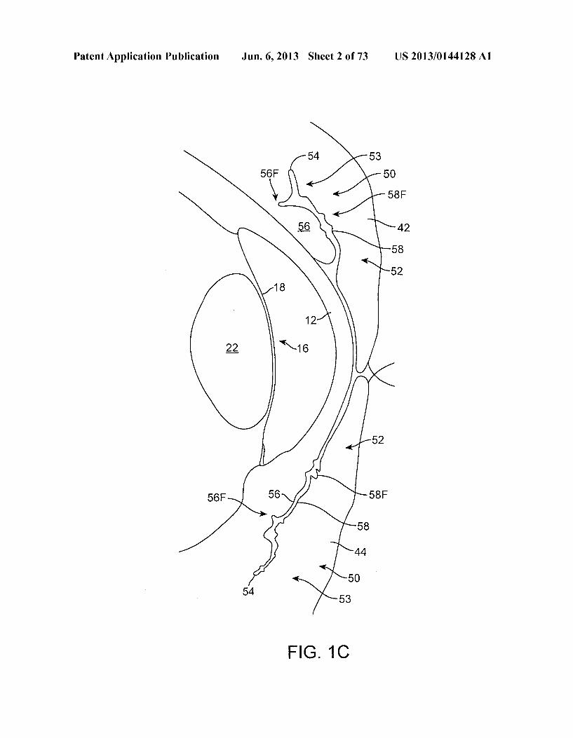
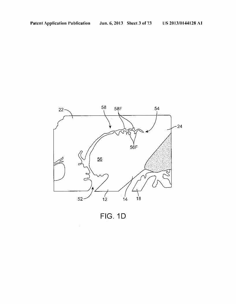
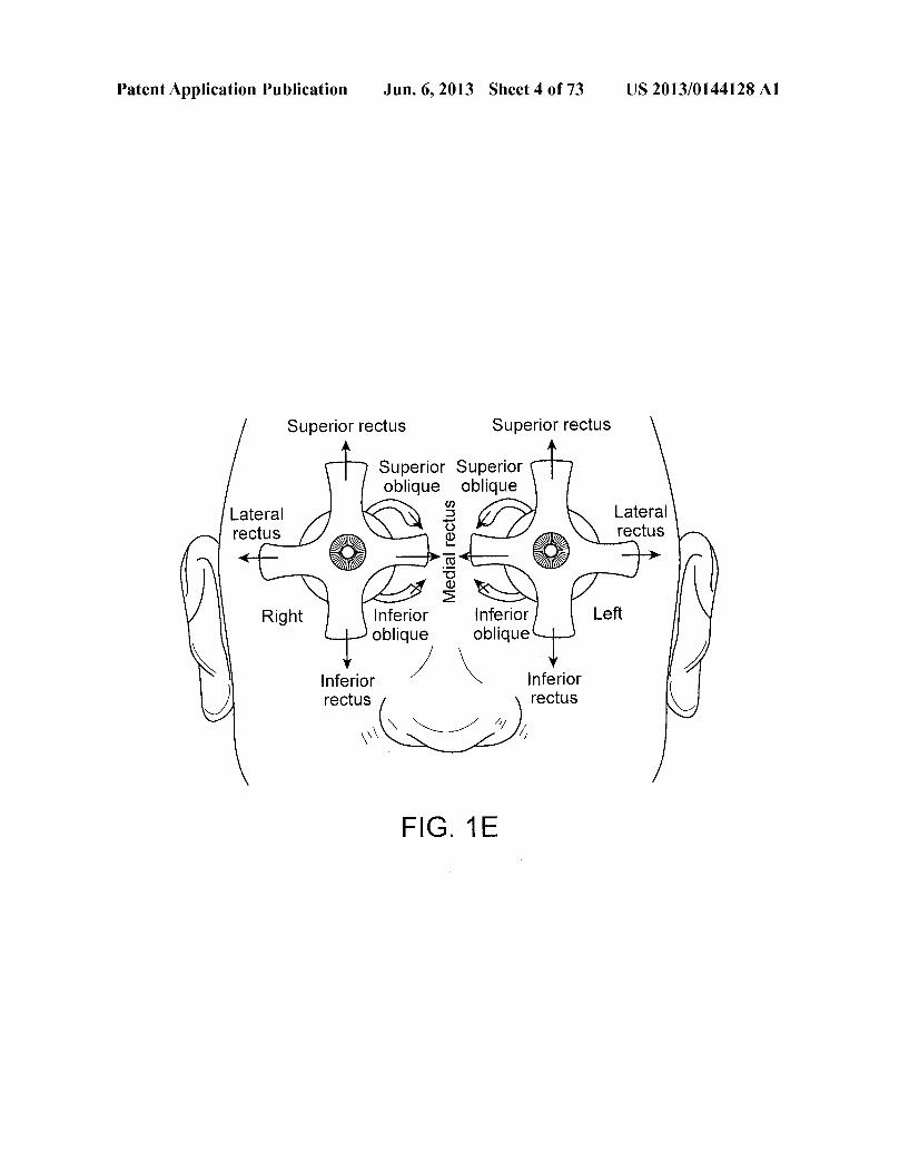
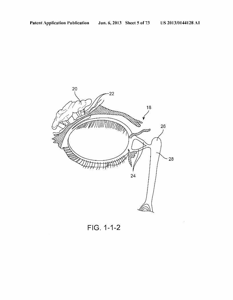
0021 FIG.1C side sectional view of the conjunctiva of the upper and lower lids of the eye as in FIGS. 1A and 1B, in accordance with an embodiment; 0022 FIG. 1D shows a side sectional view of the upper lid of the eye as in FIGS. 1A to 1C and the folds of the conjunc tiva, in accordance with an embodiment; 0023 FIG.1E shows muscles of a pair of eyes that provide cyclotorsion of the eye suitable for combination with an ocu lar insert, in accordance with an embodiment; 0024 FIG. 1-1-2 shows an anatomical tissue structure of an eye suitable for treatment with ocular inserts; 0025 FIG. 1-2-1 shows an embodiment of a therapeutic system comprising an ocular insert, that may also include an insertion device, a configuration altering material that dis Solves (or Swells, weakens, tightens, or effects some other activation mechanism) to reconfigure the implant from an insertion configuration to a deployed configuration, or the like: 0026 FIGS. 1-2-2 and 1-2-3 show a top view and cross sectional view of the therapeutic system shown in FIG. 1-2-1: 0027 FIG. 1-2-4 shows an embodiment of the therapeutic system where the ring comprises two radially outwardly and/ or anteriorly extending protrusions or bumps on opposed portions of its surface; 0028 FIG. 1-2-5 shows an alternative embodiment of the ring-shaped therapeutic device system. In this embodiment, a crescent or banana-shaped reservoir is attached to the inferior portion of the ocular insert: 0029 FIGS. 1-3-1 to 1-3-3 show another embodiment of the therapeutic system including a ring-shaped structure with a diameter of at least 8 mm, sized to fit outside the optical Zone of the cornea, and also having two or more haptics; 0030 FIGS. 1-4-1 to 1-4-2 show an alternate embodiment of the therapeutic system in which two or more concentric ring-shaped structures are held together by four or more hap tics; 0031 FIG. 1-4-3 shows an embodiment that employs an eccentric design Such that the one or more ring portions or arc segments are present in the inferior area of the ring to target delivery to the area of the eye where tears may more readily pool, as in the cul-de-sac: 0032 FIGS. 1-5-1 through 1-5-3 show a serpentine embodiment of therapeutic system which shows an expand able ocular insert: 0033 FIGS. 1-6-1 and 1-6-2 show another embodiment where the second cushioning structure comprises two hydro gel Scleral contact lenses attached to each other, so as to sandwich the first rigid structure between them; 0034 FIG. 1-7-1 shows a close-up of an exemplary ocular insert of the therapeutic device system in which the second structure is disposed throughout the circumferential length of the first structure; 0035 FIG. 1-7-2 shows a cross-section of a therapeutic device system comprising a second structure with a tapered outer and/or inner edge; 0036 FIG. 1-7-3 shows a cross-section of a therapeutic device system comprising a second structure with a beveled edge; 0037 FIG. 1-7-4 shows a cross-section of a therapeutic device system comprising a second structure with a rounded edge;
US 2013/0144128A1
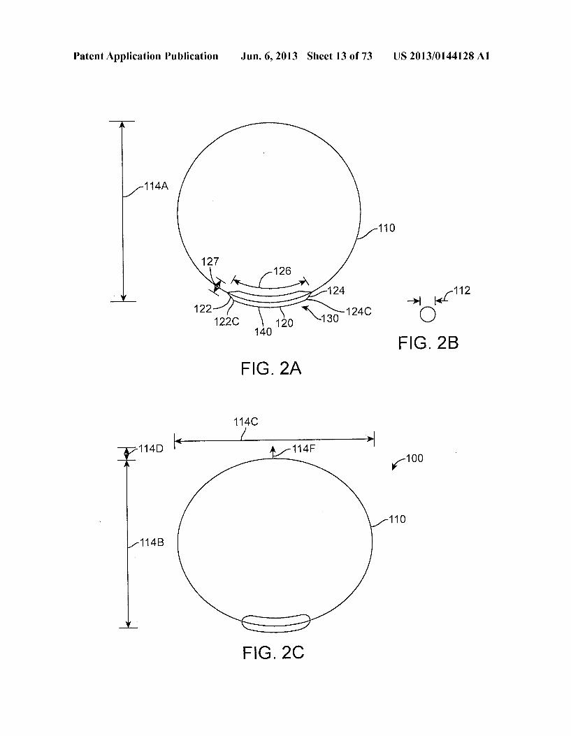
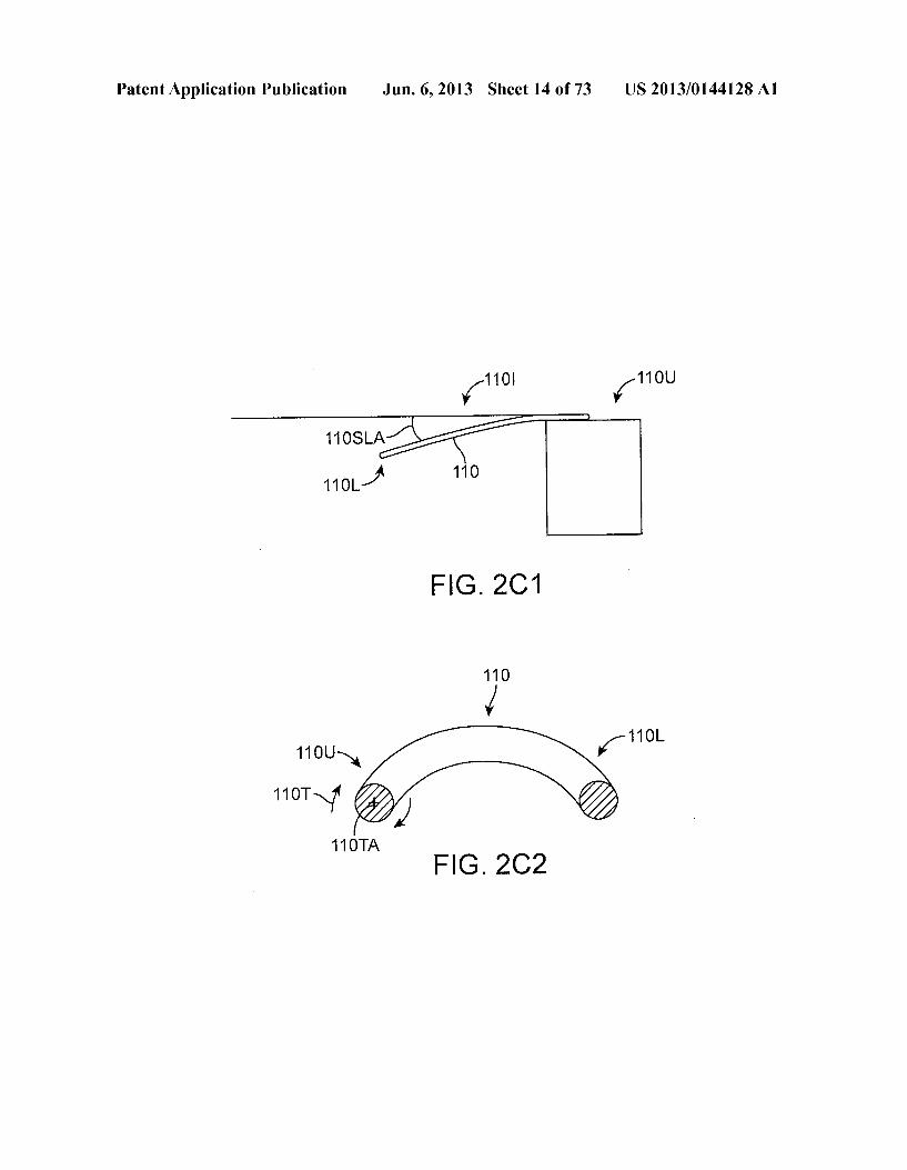
0038 FIG. 1-8-1 shows a therapeutic device system with a second structure that may have an anterior and/or posterior surface that can be shaped as well to the radius of curvature of the eye; 0039 FIG. 1-9-1 shows the second, cushioning structure disposed over discrete portions of the length of the first Sup porting structure; 0040 FIG. 2A shows an insert for insertion into an eye, in accordance with an embodiment; 0041 FIG. 2B shows a cross sectional view of a retention structure, in accordance with an embodiment; 0042 FIG. 2C shows an insert as in FIGS. 2A and 2B deflected in response to placement in an eye and correspond ing force to urge the retention structure outward, in accor dance with an embodiment; 0.043 FIG. 2C1 shows a retention structure self-loaded and deflected at an angle, in accordance with an embodiment; 0044 FIG. 2C2 shows torsion of a retention structure at a
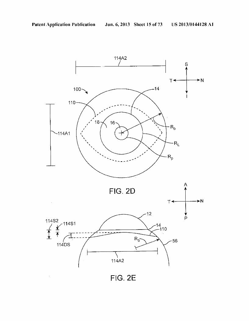
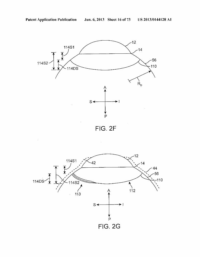
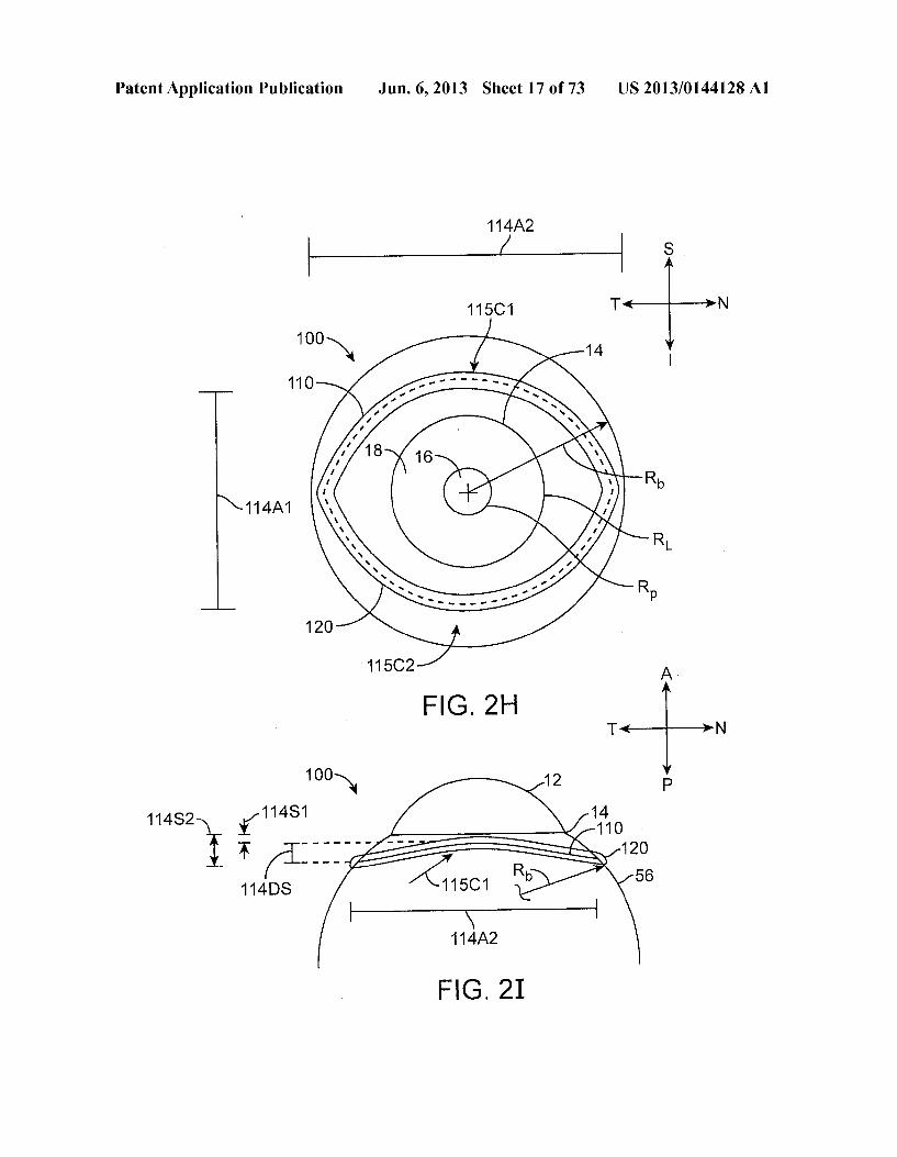
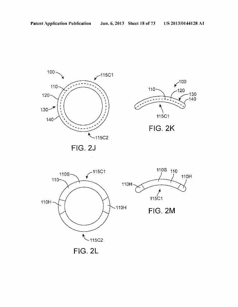
first location at resistance to twisting, in accordance with an embodiment; 0045 FIG. 2D shows an insert having a preformed oval shape extending along a convex spherical Surface. Such that the insert extends away from a plane and resists deflection toward the plane, in accordance with an embodiment; 0046 FIG. 2E shows a view of an insert as in FIG. 2D extending along nasal-temporal and anterior posterior direc tions, in accordance with an embodiment; 0047 FIG.2F shows a side view of an insert as in FIG. 2D extending along Superior-inferior and anterior posterior directions, in accordance with an embodiment; 0048 FIG. 2G shows an insert having a preformed oval shape extending along a convex spherical Surface and in which the oval ring has a first portion corresponding to the upper conjunctival sac and a second portion corresponding to the lower conjunctival sac, in which the second portion cor responding to the lower conjunctival sac has a thinner cross section than the first portion corresponding to the upper con junctival sac, Such that the ring extends away from a plane and resists deflection toward the plane and places the second portion on the bulbar conjunctiva when the first portion is retained with the upper lid, in accordance with an embodi ment, 0049 FIG.2H shows an insert comprising a support struc ture and a retention structure having a preformed oval shape extending along a convex spherical Surface, such that the insert extends away from a plane and resists deflection toward the plane, in accordance with an embodiment; 0050 FIG.2I shows a top view of an insert as in FIG. 214 extending along nasal-temporal and anterior posterior direc tions, in accordance with an embodiment; 0051 FIG.2J shows an insert comprising a support struc ture and a retention structure having a preformed curved annular shape corresponding to the eyelid. Such that the insert extends away from a plane and resists deflection toward the plane, in accordance with an embodiment; 0052 FIG. 2K shows a top view of an insert as in FIG.2J extending along nasal-temporal and anterior posterior direc tions and having the preformed curved surface corresponding to the eyelid along the nasal temporal direction to fit the eye, in accordance with an embodiment; 0053 FIG. 2L shows an insert comprising a retention structure comprising hinge portion and a stiff portion having a preformed curved annular shape corresponding to the eye
Jun. 6, 2013
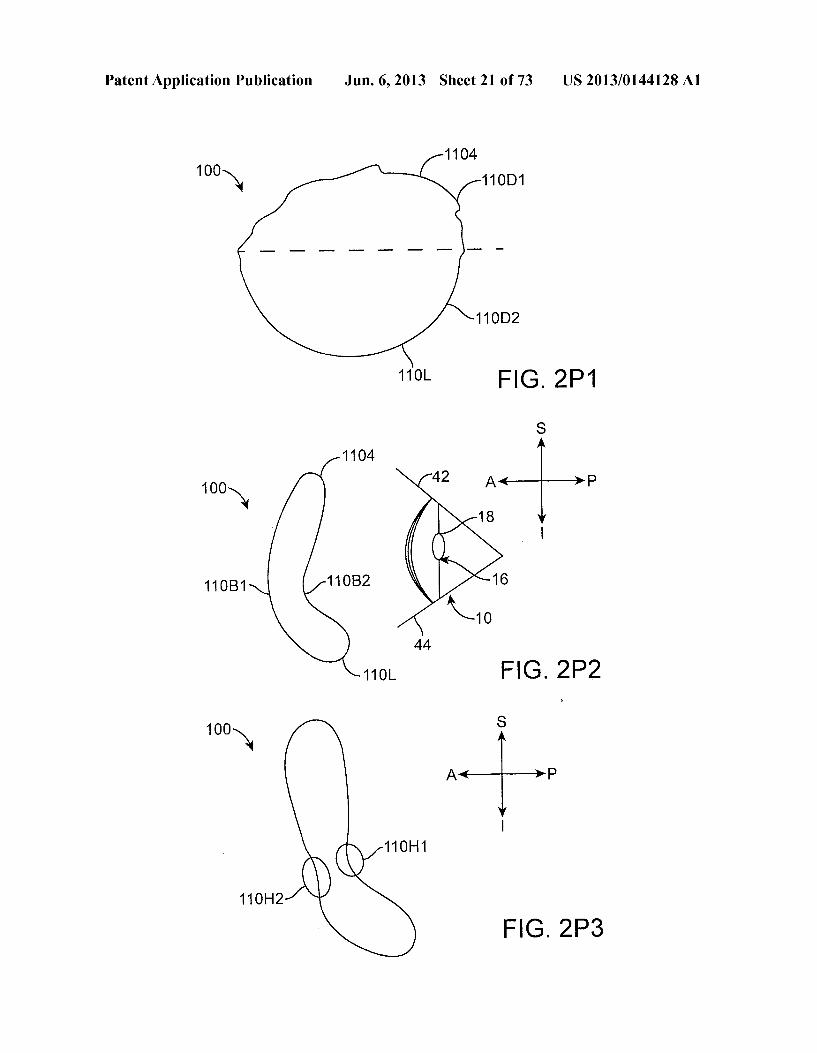
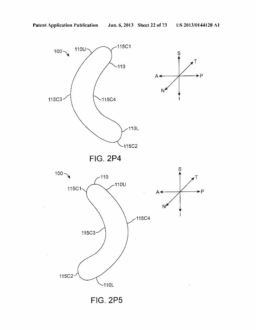
lid, Such that the insert extends away from a plane and resists deflection toward the plane, in accordance with an embodi ment; 0054 FIG.2M shows a top view of an insert as in FIG.2L extending along nasal-temporal and anterior posterior direc tions and having the stiff preformed curved surface corre sponding to the eyelid along the nasal temporal direction to fit the eye, in accordance with an embodiment; 0055 FIG.2N shows an isometric view of an insert having a 3-D shape profile corresponding to a saddle having positive curvature along the nasal and temporal portions and opposing negative curvature along the inferior and Superior portions, Such that the nasal and temporal portions are posterior to the inferior and Superior portions when placed, in accordance with an embodiment; 0056 FIG.2O shows an isometric view of an insert having a 3-D shape profile corresponding to a saddle having negative curvature along the nasal and temporal portions and opposing positive curvature along the inferior and Superior portions, Such that the nasal and temporal portions are anterior to the inferior and Superior portions when placed, in accordance with an embodiment; 0057 FIG. 2P1 shows an insert comprising a retention structure having an upper portion comprising a first durom eter and a lower portion comprising a second durometer, in accordance with an embodiment; 0.058 FIG. 2P2 shows an insert comprising a retention structure having an upper portion and a lower portion in which the lower portion is curved inward toward the eye, for example with a lower bend, in accordance with an embodi ment; 0059 FIG. 2P3 shows an insert comprising a retention structure having a hinges to couple an upper portion to a lower portion and allow the upper portion to Swing toward the lower portion, in accordance with an embodiment; 0060 FIG. 2P4 shows an insert comprising a retention structure having a first upper portion and a second lower portion with bias curve such that the upper and lower portions extend posteriorly to the nasal and temporal portions prior to placement, in accordance with an embodiment; 0061 FIG. 2P5 shows an insert comprising a retention structure having a first upper portion and a second lower portion with bias curve such that the upper and lower portions extend anteriorly to the nasal and temporal portions prior to placement, in accordance with an embodiment; 0062 FIG. 2P6 shows an insert comprising a retention structure having an oblong shape and having first upper por tion and a second lower portion in which the upper portion comprises an elongate oval shape portion to extend into the upperformix and the lower portion comprises a shorter wider oval shape to extend into the lowerformix, in accordance with an embodiment; 0063 FIG. 2P7 shows an insert comprising a retention structure comprising an upper portion and a lower portion coupled with hinges so as to define an elliptical shape, in accordance with an embodiment; 0064 FIG. 2P8 shows an insert comprising a flexible redundant retention structure to seat the retention structure in the eye, in accordance with an embodiment; 0065 FIG. 2P9 shows an insert comprising an upper anchor, in accordance with an embodiment; 0.066 FIG. 2P10 shows an insert comprising a lower anchor to resist pull of the round structure, in accordance with an embodiment;
US 2013/0144128A1
0067 FIG. 2CR shows an insert comprising a retention structure configured to exert at least Some pressure on the conjunctiva to retain the insert, in accordance with an embodiment; 0068 FIG. 2R shows an insert comprising a retention structure having a curved portion to extend laterally to the temporal formix of the eye, in accordance with an embodi ment, 0069 FIG. 2S shows an insert comprising a retention structure having an outer curved portion to extend laterally to the temporal formix of the eye, in accordance with an embodi ment, 0070 FIG. 2T shows an insert comprising a retention structure having an outeranchor portion to extend laterally to the temporal formix of the eye, in accordance with an embodi ment, 0071 FIGS. 2U and 2V show an insert comprising a reten tion structure having an upper portion sized to extend into the upperformix and a lower portion sized to extend into a lower formix with an intermediate portion between the upper and lower portions and wherein the upper and lower portions curve posteriorly from the intermediate portion to fit the upper and lowerformices, respectively, in accordance with an embodiment; 0072 FIG. 2W shows an insert comprising an upper por tion comprising a hydrophilic Surface and a lower portion comprising a hydrophobic Surface, in accordance with an embodiment; 0073 FIG. 2X1 and 2X2 show front and side views, respectively, of an insert comprising an upper portion and a lower portion and a stiff portions to angularly bias the upper portion and the lower portion toward each other, in accor dance with an embodiment; 0074 FIG.2Y shows an insert comprising an expandable retention structure to allow the insert to be stretched to fit the eye, in accordance with an embodiment; 0075 FIG. 2Z1 shows an insert comprising a retention structure having an upper portion and a lower portion coupled with a variable joint to as to vary a size of the retention structure and insert, in accordance with an embodiment; 0076 FIG. 2Z2 shows a telescopic joint of an insert as in FIG. 2Z1, in accordance with an embodiment; 0077 FIG.273 shows a shock absorbing spring joint of an insert as in FIG. 2Z1, in accordance with an embodiment; 0078 FIG. 2Z4 shows a ratcheting joint of an insert as in FIG. 2Z1, in accordance with an embodiment; 007.9 FIGS. 275 and 2Z6 show front and side views, respectively, of an insert comprising an elongate shapehaving upper and lower portions sized to extend into upper and lower formices, respectively, so as to provide Substantially greater amounts of therapeutic agent than the intermediate portions locatable near the lateral and medial canthus, in accordance with an embodiment; 0080 FIGS. 2Z7 and 2Z8 show front and side views, respectively, of a rigid insert having a curved shape sized to fit the eye of the patient such that the insert can be worn com fortably for an extended time, in accordance with an embodi ment, I0081 FIG. 3A1 shows an insert placed between folds of conjunctiva, in accordance with an embodiment; 0082 FIG. 3 A2 shows a fold of conjunctiva receiving an insert, in accordance with an embodiment; 0083 FIG. 3A3 shows an insert sized to fit between folds of conjunctiva, in accordance with an embodiment;
Jun. 6, 2013
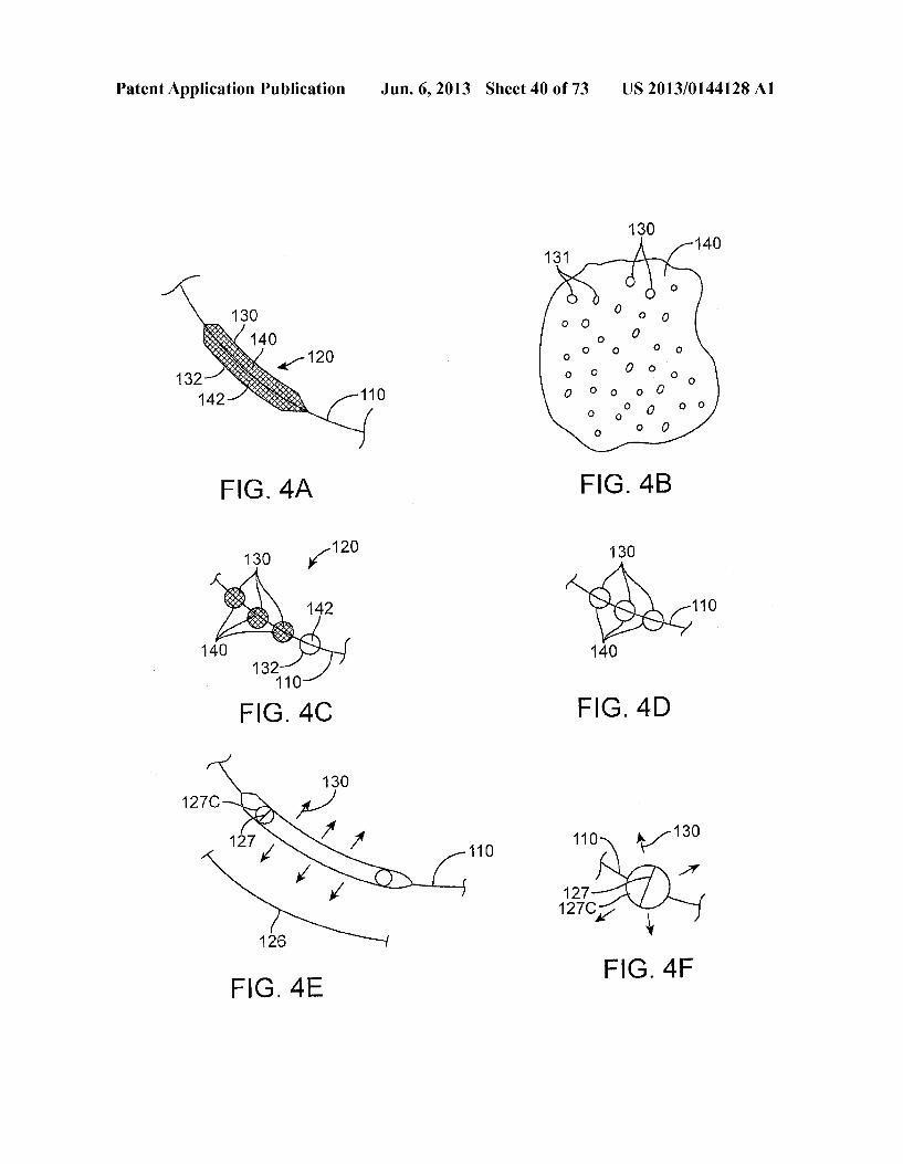
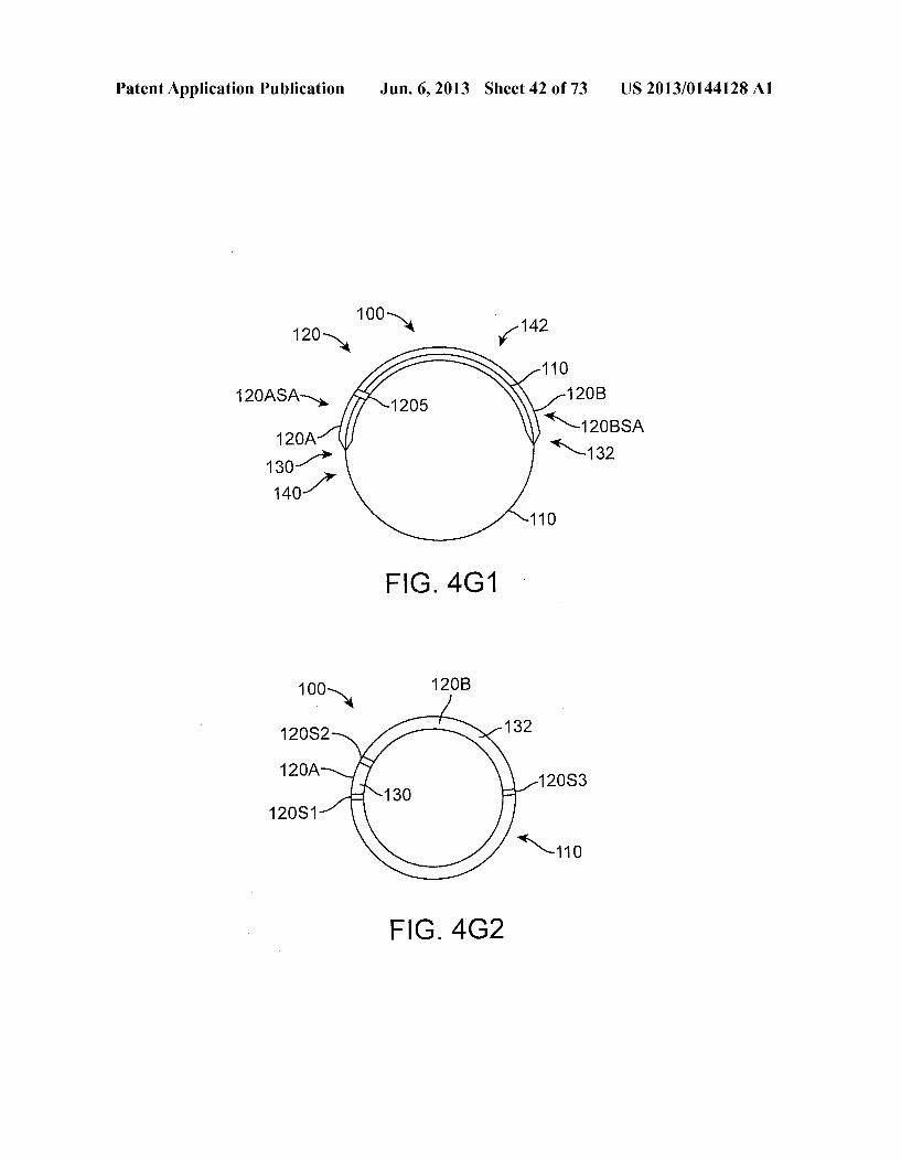
008.4 FIG. 3A4 shows a retention structure of an insert as in FIGS. 2A to 2G placed on an eye such that the retention structure has fit into one or more of a plurality of folds of the bulbar conjunctiva, in accordance with an embodiment; 0085 FIG. 3B shows a retention structure under a fold of bulbar conjunctiva, in accordance with an embodiment; 0086 FIGS. 3C1 to 3C3 show a retention structure under a fold of bulbar conjunctiva moving with rotation of the eye, in accordance with an embodiment; I0087 FIG. 3D shows an initial inferior placement of an insert comprising a retention structure, in accordance with an embodiment; I0088 FIG.3E show an insert initially placed as in FIG. 3D which has moved rotationally along the conjunctiva about an axis of rotation extending through a pupil of the eye, in accordance with an embodiment; 0089 FIG. 3F shows the an insert located at an inferior temporal location of the conjunctiva of the eye and the orbit, in accordance with an embodiment; 0090 FIG. 3G shows the support structure placed superi orly, in accordance with an embodiment; 0091 FIG. 3G-1 shows the support structure placed supe riorly at an initial location of the Superior conjunctival sac, in accordance with an embodiment; 0092 FIG. 3G-2 shows the support structure seated in the cul-de-sac of the Superior conjunctival sac following place ment as in FIG. 3G-1, in accordance with an embodiment; 0093 FIG. 3H shows the support structure located at an inferior nasal location of the eye so as to extend near the caruncle, in accordance with an embodiment; 0094 FIG.3I shows the support structure placed at a tem poral location of the eye, in accordance with an embodiment; 0.095 FIG. 3J shows retention structure comprising a first portion having a first resistance to deflection and a second portion having a second resistance to deflection less than the first portion, in accordance with an embodiment; 0096 FIG. 3J-1 shows a side cross sectional view of the retention structure as in FIG. 3J, in accordance with an embodiment; 0097 FIG.3K shows an insert comprising a support struc ture comprising a matrix of therapeutic agent on the retention structure as in FIG. 3J, in accordance with an embodiment; 0.098 FIG. 3L shows an insert comprising a lubricous coating, in accordance with an embodiment; 0099 FIG.3L-1 shows a layer of the lubricous coating on the Surface of the matrix containing the therapeutic agent as in FIG. 3L, in accordance with an embodiment; 0100 FIG. 4A shows an insert comprising a plurality of therapeutic agents loaded on a first portion of the Support structure and a second portion of the Support structure, in accordance with an embodiment; 0101 FIG. 4B shows a matrix comprising inclusions of a therapeutic agent, in accordance with an embodiment; 0102 FIG.4C shows a plurality of support structures com prising a plurality of therapeutic agents placed together on a retention structure at a location corresponding to placement along an inferior temporal portion of the conjunctiva of the eye, in accordance with an embodiment; 0103 FIG. 4D shows a plurality of support structures along a retention structure, in accordance with an embodi ment; 0104 FIG. 4E shows release of a therapeutic agent from a matrix having a surface area sized to treat the patient for an extended time, in accordance with an embodiment;
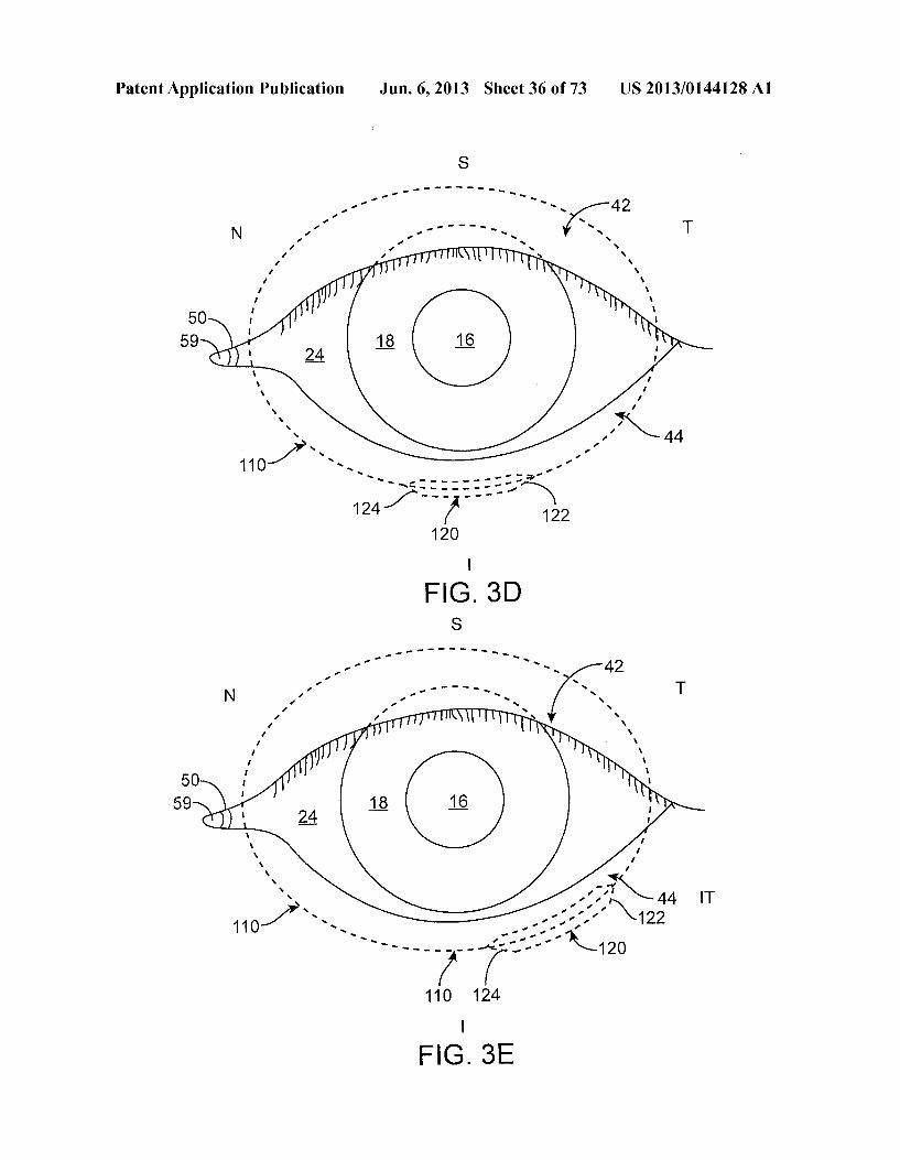
US 2013/0144128A1
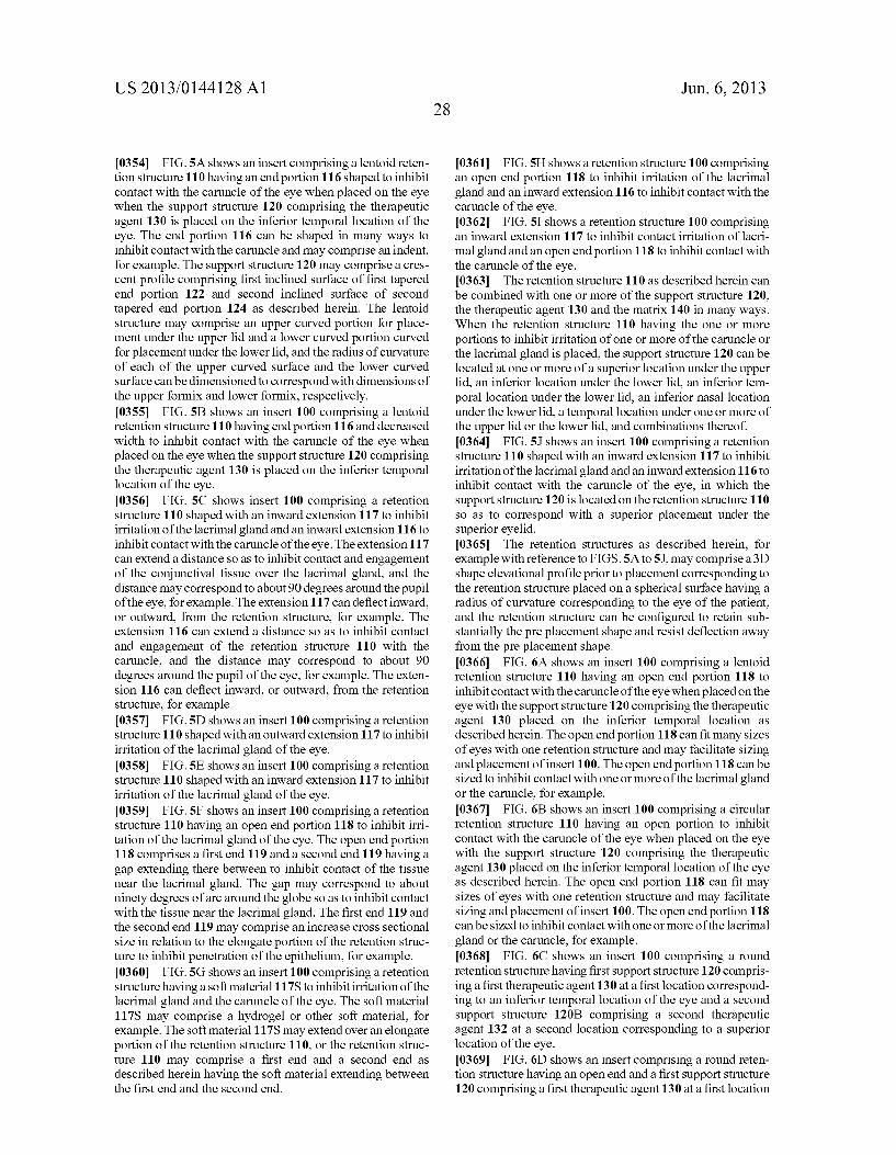
0105 FIG. 4F shows release of a therapeutic agent from a spherical Surface of a spherical matrix structure located on a retention structure, in which the spherical Surface has an area to release therapeutic amounts of the therapeutic agent for the extended time, in accordance with an embodiment; 0106 FIG. 4G shows a plurality of at least three support structures along a retention structure comprising a plurality of at least three therapeutic agents, in accordance with an embodiment; 0107 FIG. 4G-1 shows a plurality of support structures comprising a first therapeutic agent contained within a first matrix and a second therapeutic agent contained within a second matrix, in accordance with an embodiment; 0108 FIG. 4G-2 shows a retention structure comprising a ring, the ring comprising a plurality of ring segments, in accordance with an embodiment; 0109 FIG. 4G-3 shows an annular insert comprising a retention structure comprising an annular ring and an annular Support comprising a matrix of therapeutic agent covering the retention structure, in accordance with an embodiment; 0110 FIG.4G-4 shows across-sectional view of the reten tion structure and support structure of FIG. 4G-3, in accor dance with an embodiment; 0111 FIG. 4H shows an insert comprising a structure hav ing an erodible material to release a therapeutic agent for an extended time, in accordance with an embodiment; 0112 FIG. 4I shows a transverse cross sectional view of the structure comprising the erodible material as in FIG. 4H. in accordance with an embodiment; 0113 FIG. 4J shows a side cross sectional view of the structure comprising the erodible material as in FIGS. 4H and 4I, in accordance with an embodiment; 0114 FIG. 4K shows a container having a channel occluded with an erodible material as in FIGS. 4H to 4J, in accordance with an embodiment; 0115 FIG. 4L shows the container as in FIG. 4K having the material eroded away from the channel to release the therapeutic agent, in accordance with an embodiment; 0116 FIG. 4M shows a pump to release a therapeutic agent with pulsatile flow, in accordance with an embodiment; 0117 FIG. 4N shows a release profile of therapeutic agent of the pump as in FIG. 4M, in accordance with an embodi ment, 0118 FIG.4O shows a pressure profile of a chamber of the pump as in FIGS. 4M and 4N, in accordance with an embodi ment, 0119 FIG. 4P shows reservoir chamber comprising inclu sions of a therapeutic agent coupled to an osmotic pump with a piston so as to release therapeutic agent with pulsatile flow, in accordance with an embodiment; 0120 FIG. 4Q shows reservoir chamber comprising inclu sions of a therapeutic agent coupled to valve of an osmotic pump so as to release therapeutic agent with pulsatile flow, in accordance with an embodiment; 0121 FIG. 5A shows an insert comprising a lentoid reten tion structure having an end portion shaped to inhibit contact with the caruncle of the eye when the support structure com prising the therapeutic agent is placed on the inferior tempo ral location of the eye, in accordance with an embodiment; 0122 FIG. 5B shows an insert comprising a lentoid reten tion structure having decreased width to inhibit contact with the caruncle of the eye when the Support structure comprising the therapeutic agent is placed on the inferior temporal loca tion of the eye, in accordance with an embodiment;
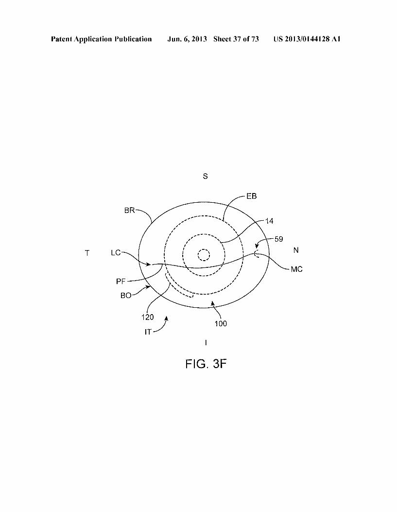
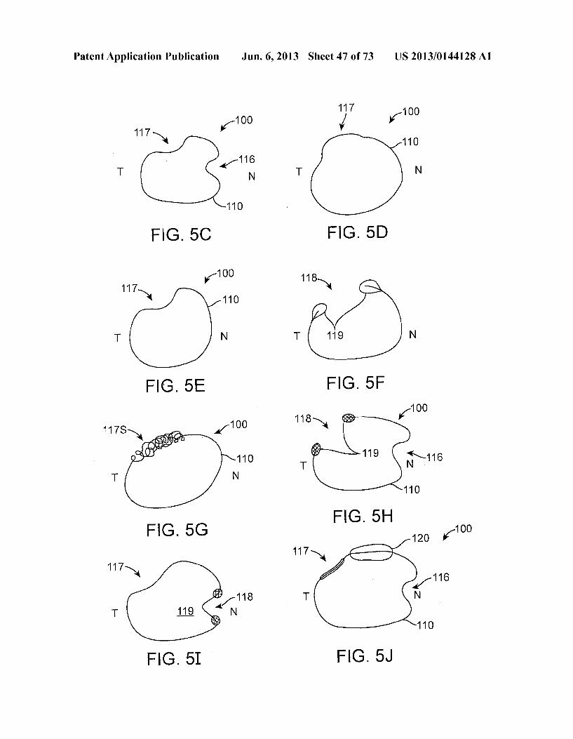
Jun. 6, 2013
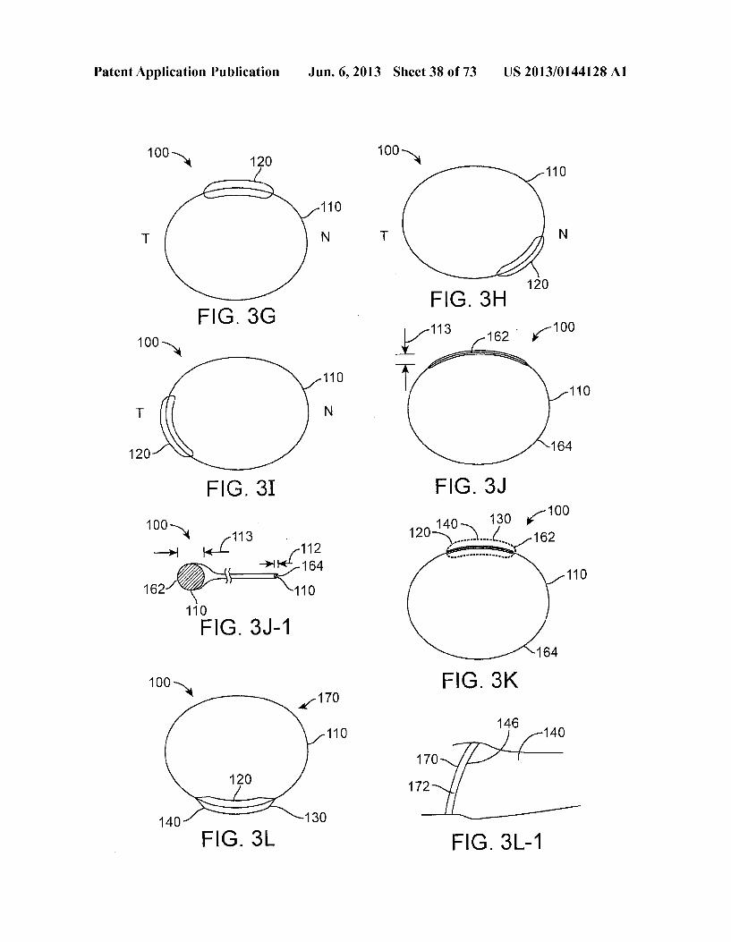
I0123 FIG. 5C shows an insert comprising a retention structure shaped with an inward extension to inhibit irritation of the lacrimal gland and an inward extension to inhibit con tact with the caruncle of the eye, in accordance with an embodiment; 0.124 FIG. 5D shows an insert comprising a retention structure shaped with an outward extension to inhibit irrita tion of the lacrimal gland of the eye, in accordance with an embodiment; 0.125 FIG. 5E shows an insert comprising a retention structure shaped with an inward extension to inhibit irritation of the lacrimal gland of the eye, in accordance with an embodiment; 0.126 FIG. 5F shows an insert comprising a retention structure having an open end portion to inhibitirritation of the lacrimal gland of the eye, in accordance with an embodiment; I0127 FIG. 5G shows an insert comprising a retention structure having a soft material to inhibit irritation of the lacrimal gland and the caruncle of the eye, in accordance with an embodiment; I0128 FIG. 5H shows a retention structure comprising an open end portion to inhibit irritation of the lacrimal gland and an inward extension portion to inhibit contact with the caruncle of the eye, in accordance with an embodiment; I0129 FIG. 5I shows a retention structure comprising an inward extension portion to inhibit contact irritation of lacri mal gland and an open end portion to inhibit contact with the caruncle of the eye, in accordance with an embodiment; 0.130 FIG. 5J shows an insert comprising a retention structure shaped with an inward extension to inhibit irritation of the lacrimal gland and an inward extension to inhibit con tact with the caruncle of the eye, in which the support struc ture is located on the retention structure so as to correspond with a Superior placement under the Superior eyelid, in accor dance with an embodiment; I0131 FIG. 6A shows an insert comprising a lentoid reten tion structure having an open end portion to inhibit contact with the caruncle of the eye when placed on the eye with the Support structure comprising the therapeutic agent placed on the inferior temporal location, in accordance with an embodi ment; I0132 FIG. 6B shows an insert comprising a circular reten tion structure having an open portion to inhibit contact with the caruncle of the eye when placed on the eye with the Support structure comprising the therapeutic agent placed on the inferior temporal location of the eye, in accordance with an embodiment; 0.133 FIG. 6C shows an insert comprising a round reten tion structure having first Support structure comprising a first therapeutic agent at a first location corresponding to an infe rior temporal location of the eye and a second Support struc ture comprising a second therapeutic agent at a second loca tion corresponding to a Superior location of the eye, in accordance with an embodiment; 0.134 FIG. 6D shows an insert comprising a round reten tion structure having an open end and a first Support structure comprising a first therapeutic agent at a first location corre sponding to an inferior temporal location of the eye and a second Support structure comprising a second therapeutic agent at a second location corresponding to a Superior loca tion of the eye, in accordance with an embodiment; I0135 FIGS. 7A and 7B show planand side cross-sectional views, respectively, of an insert comprising an outer retention
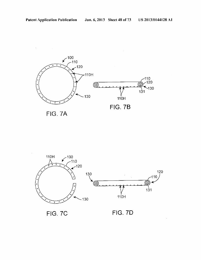
US 2013/0144128A1
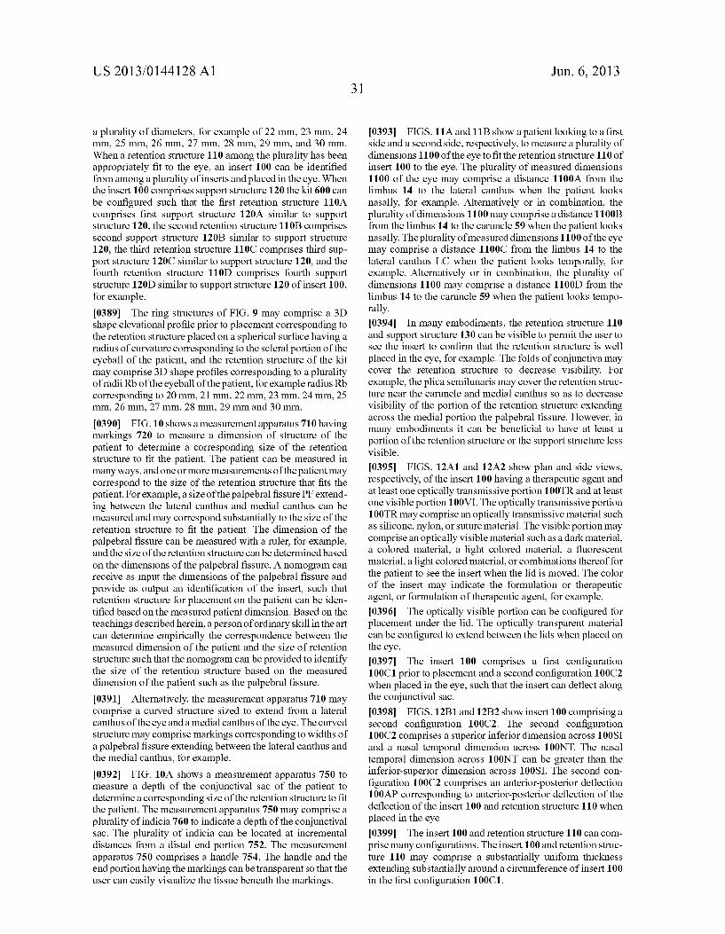
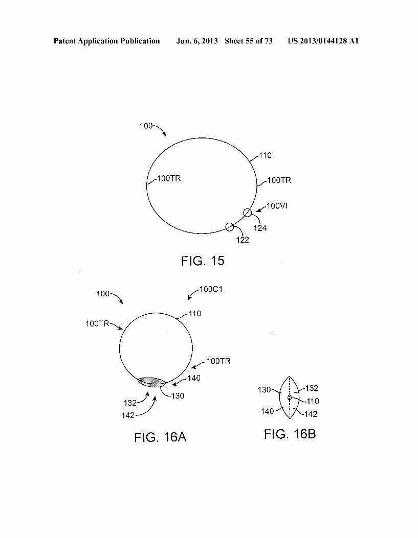
structure having a resistance to deflection to remain within the eye for an extended time, in accordance with an embodiment; 0.136 FIGS. 7C and 7D show plan and side cross-sectional views, respectively, of an arcuate C-shaped insert comprising an outer retention structure having a resistance to deflection to remain within the eye for an extended time, in accordance with an embodiment; 0137 FIG. 8A shows treatment of a retention structure of an insert to increase a resistance to deflection of the retention structure, in accordance with an embodiment; 0138 FIG. 8B shows in situ forming of a retention struc ture of an insert, in accordance with an embodiment; 0139 FIG.8C shows a flowable material placedon the eye to form at least a portion of the insert, in accordance with an embodiment; 0140 FIG.8D depicts syringe system300 with barrel 302, needle hilt 303, needle 304 with rounded tip306 having outlet 308 and plunger 310 with pusher 312, in accordance with an embodiment; 0141 FIG.8E shows a syringe system being used to intro duce hydrogel precursors into the cul-de-sac, for example into the formix, with the precursors left in on or more of the cul-de-sac or the formix, in accordance with an embodiment; 0142 FIG. 9 shows a kit comprising a plurality of reten tion structures having incrementally increasing sizes to deter mine a size of the retention structure to fit the patient, in accordance with an embodiment; 0143 FIG. 10 shows a measurement apparatus to measure a dimension of structure of the patient to determine a corre sponding size of the retention structure to fit the patient, in accordance with an embodiment; 014.4 FIG. 10A shows a measurement apparatus to mea Sure a depth of the conjunctival sac of the patient to determine a corresponding size of the retention structure to fit the patient, in accordance with an embodiment; 0145 FIGS. 11A and 11B show a patient looking to a first side and a second side, respectively, to determine a dimension of the eye, in accordance with an embodiment; 0146 FIGS. 12A1 and 12A2 show plan and side views, respectively, of the insert having a therapeutic agent and at least one optically transmissive portion and at least one vis ible portion, in accordance with an embodiment; 0147 FIGS. 12B1 and 12B2 show insert 100 comprising second configuration 100C2, in accordance with an embodi ment, 0148 FIGS. 13A1 and 13A2 show a support structure configured to resist movement away from the inferior tempo ral portion of the conjunctival sac, in accordance with an embodiment; 0149 FIGS. 13B1 and 13B2 show insert 100 comprising second configuration 100C2, in accordance with an embodi ment, 0150 FIG. 14A1 and 14A2 show plane and side views, respectively, of structure comprising a first structure and a second structure spaced apart with distance to maintain the first structure and the second structure in the inferior temporal location of the conjunctival sac, in accordance with an embodiment; 0151 FIGS. 14B1 and 14B2 show the insert 100 placed along at least a portion of the conjunctival sac of an eye, in accordance with an embodiment; 0152 FIG. 15 shows insert comprising a C-shaped con figuration with retention structure comprising a first end and a second end, in accordance with an embodiment;
Jun. 6, 2013
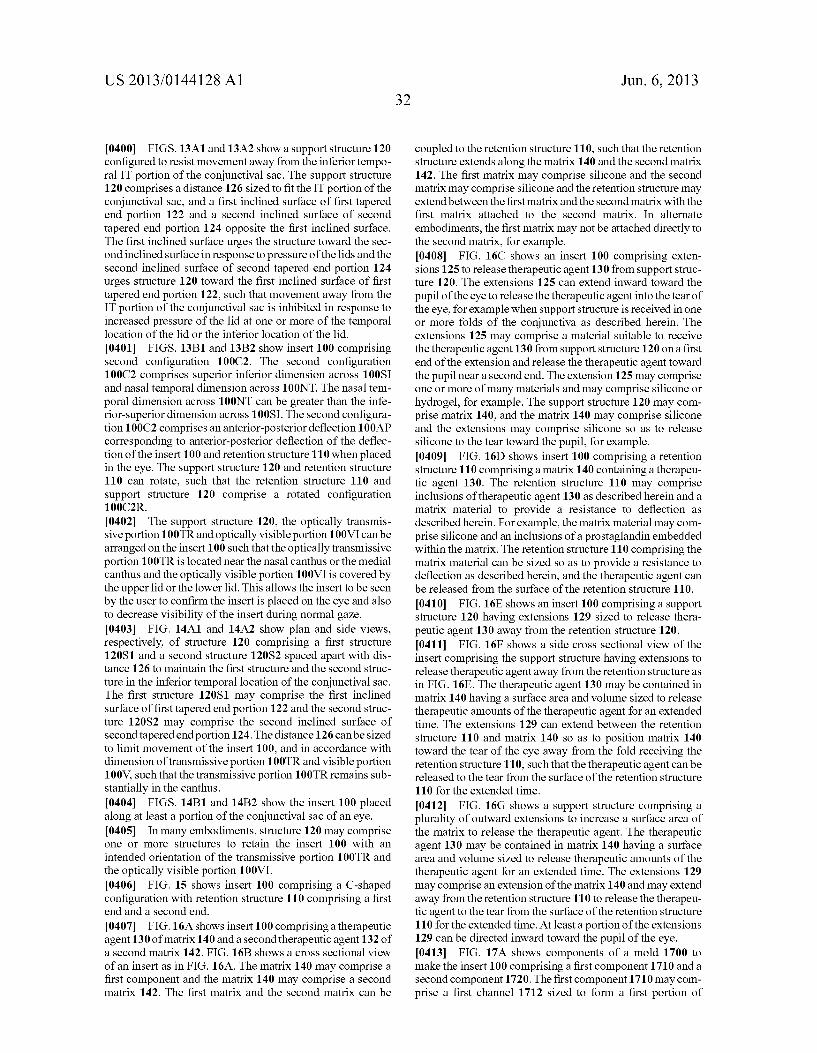
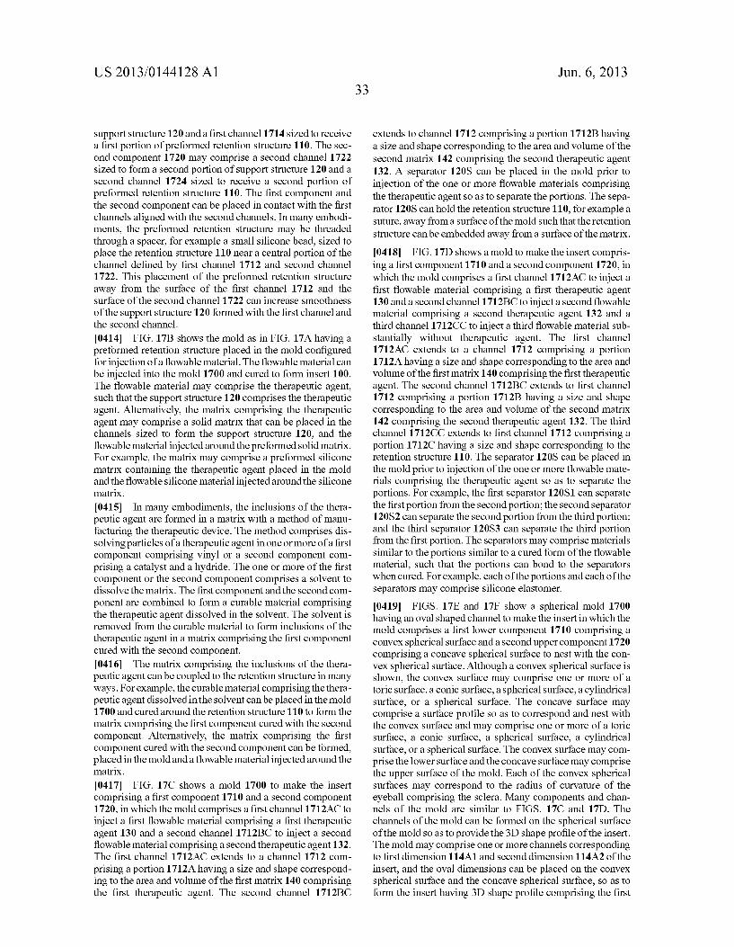
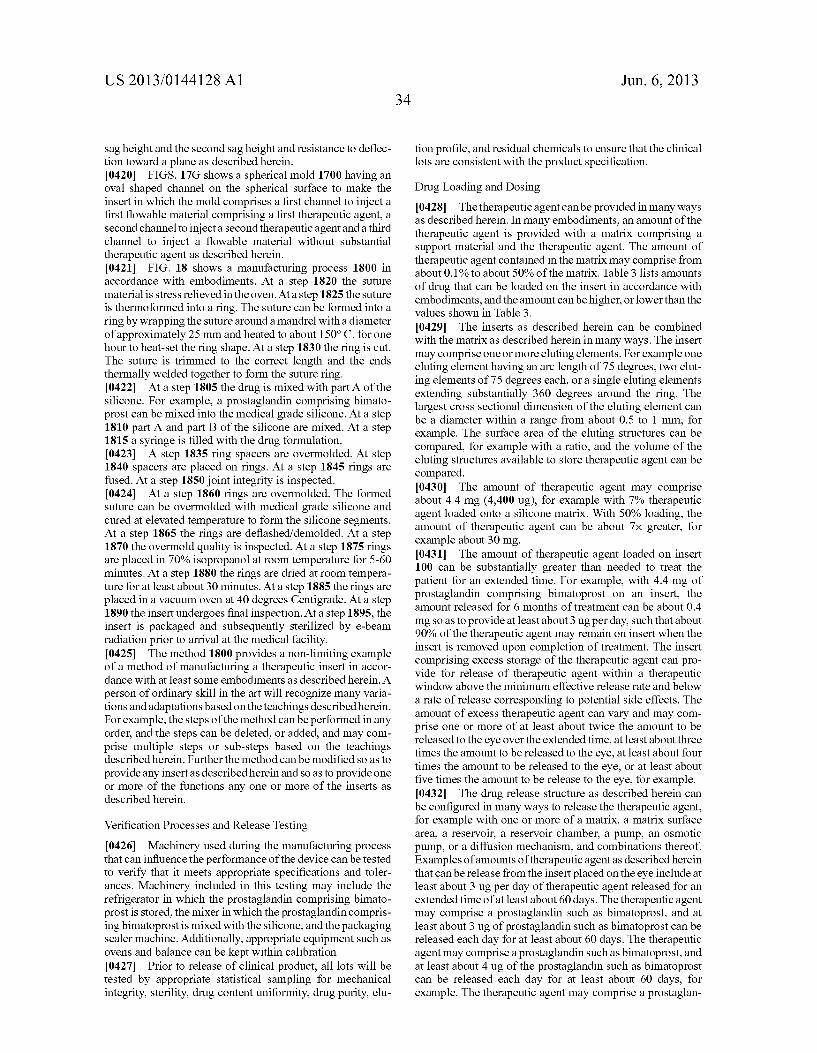
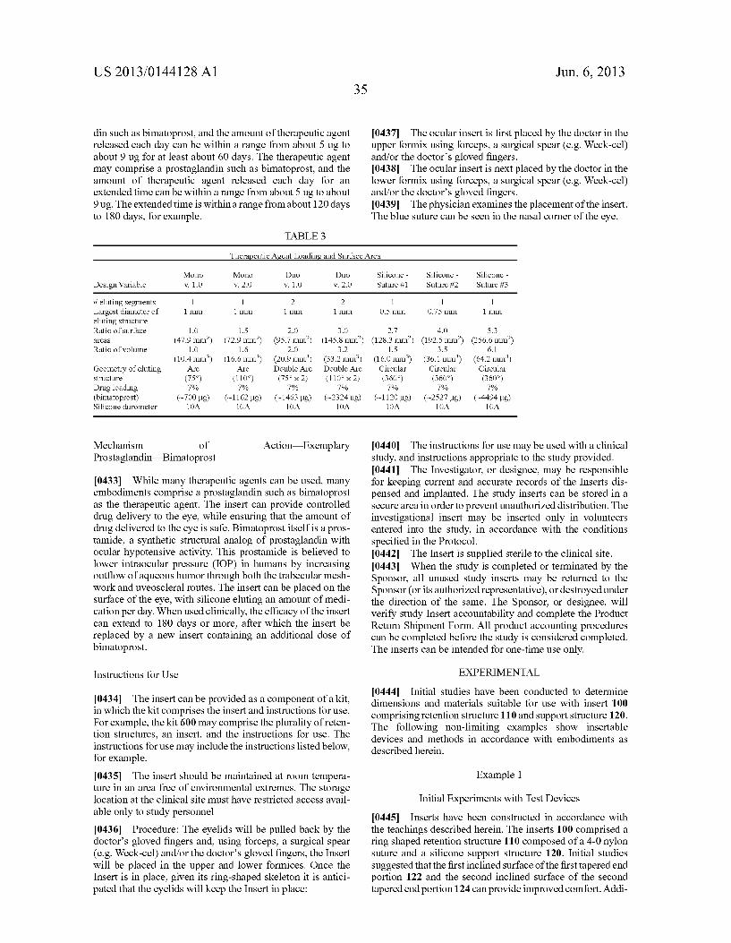
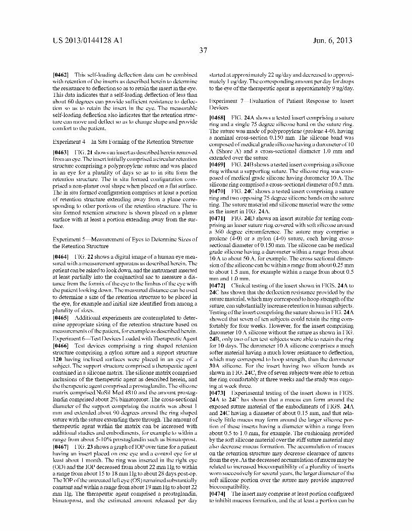
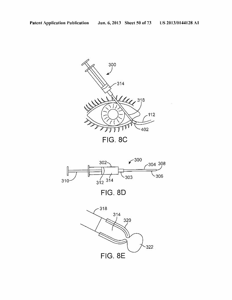
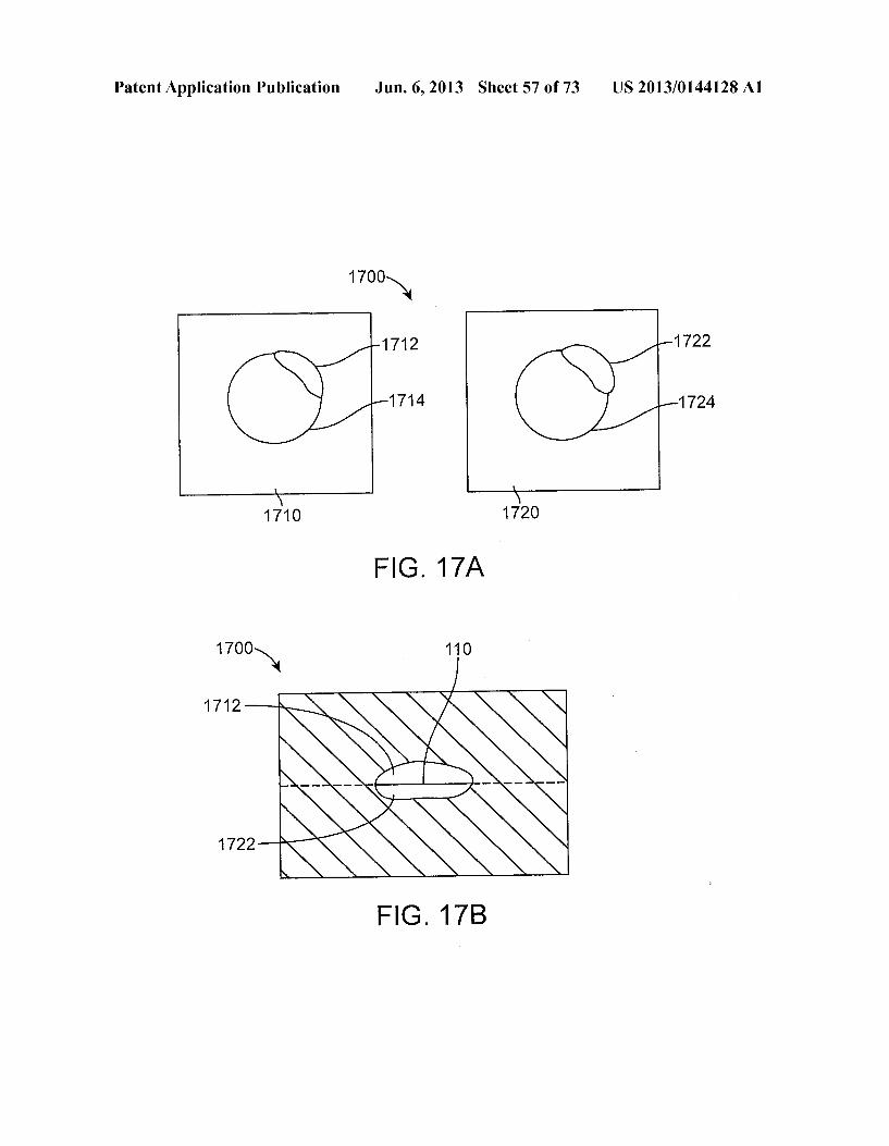
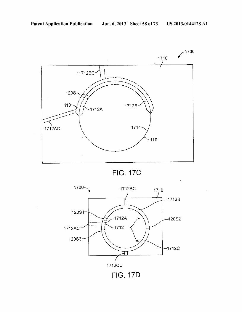
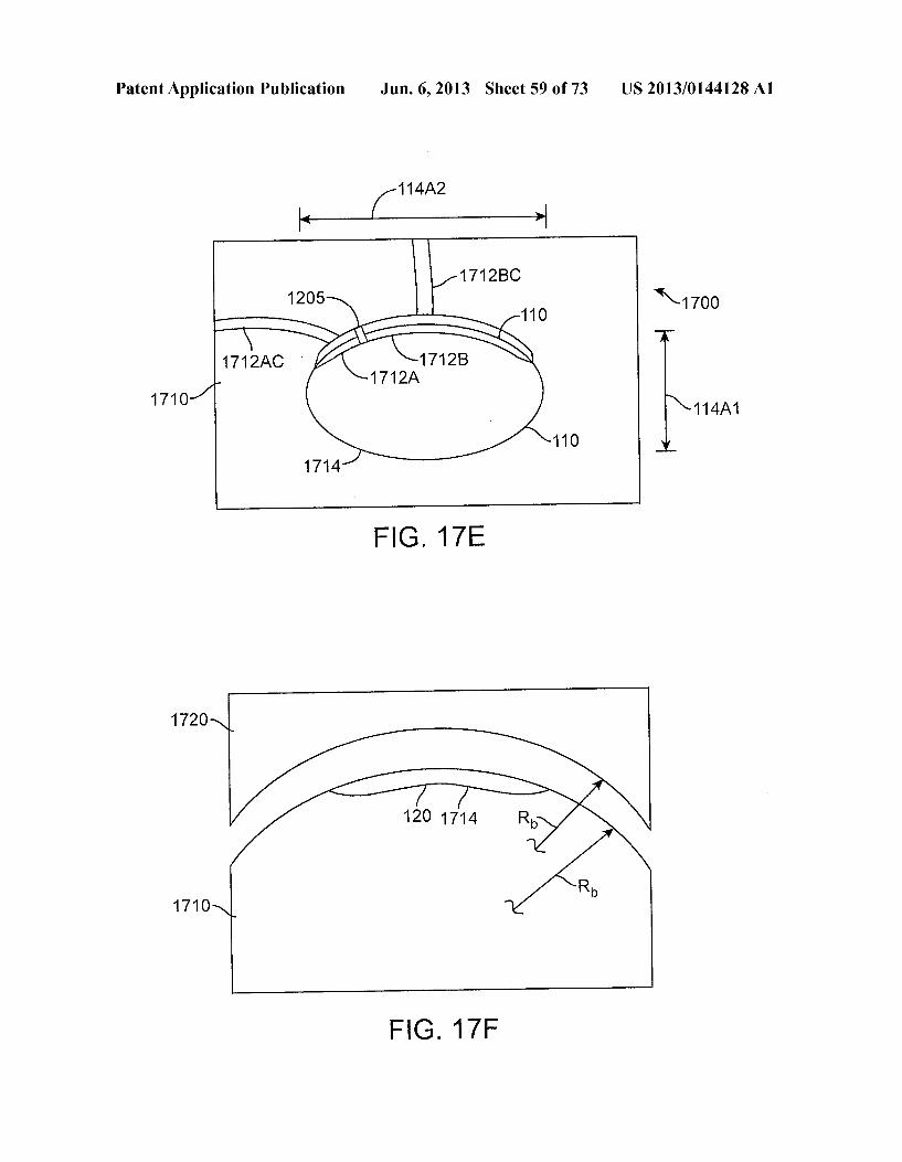
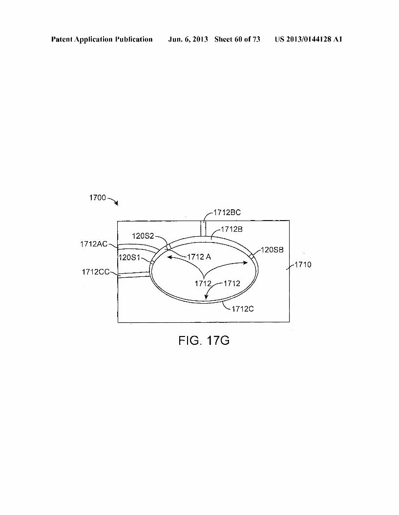
0153 FIG. 16A shows an insert comprising a therapeutic agent of matrix and a second therapeutic agent of a second matrix, in accordance with an embodiment; 0154 FIG.16B shows across sectional view of an insertas in FIG.16A, in accordance with an embodiment; 0155 FIG.16C shows an insert comprising extensions to release a therapeutic agent, in accordance with an embodi ment; 0156 FIG. 16D shows a retention structure comprising a matrix containing a therapeutic agent, in accordance with an embodiment; 0157 FIG. 16E shows an insert comprising a support structure having extensions to release therapeutic agent away from the retention structure, in accordance with an embodi ment; 0158 FIG. 16F shows a side cross sectional view of an insert comprising a Support structure having extensions to release therapeutic agent away from the retention structure as in FIG.16E, in accordance with an embodiment; 0159 FIG. 16G shows a support structure comprising a plurality of outward extensions to increase a Surface area of the matrix to release the therapeutic agent, in accordance with embodiments; 0160 FIG. 17A shows a mold to make the insert compris ing a first component and a second component, in accordance with an embodiment; (0161 FIG. 17B shows the mold as in FIG. 17A having a preformed retention structure placed in the mold configured for injection of a flowable material, in accordance with an embodiment; 0162 FIG. 17C shows a mold to make the insert compris ing a first component and a second component, in which the mold comprises a first channel to inject a first flowable mate rial comprising a first therapeutic agent and a second channel to inject a second flowable material comprising a second therapeutic agent, in accordance with an embodiment; 0163 FIG. 17D shows a mold to make the insert compris ing a first component and a second component, in which the mold comprises a first channel to inject a first flowable mate rial comprising a first therapeutic agent and a second channel to inject a second flowable material comprising a second therapeutic agent and a third channel to inject a third flowable material Substantially without therapeutic agent, in accor dance with an embodiment; 0164 FIGS. 17E and 17F show a spherical mold having an oval shaped channel to make the insert in which the mold comprises a first lower component comprising a convex spherical Surface and a second upper component comprising a concave spherical Surface to nest with the convex spherical Surface, in accordance with an embodiment; 0.165 FIGS. 17G shows a spherical mold having an oval shaped channel to make the insert in which the mold com prises a first channel to inject a first flowable material com prising a first therapeutic agent, a second channel to inject a second flowable material comprising a second therapeutic agent and a third channel to inject a flowable material without Substantial therapeutic agent, in accordance with an embodi ment; 0166 FIG. 18 shows a manufacturing process, in accor dance with an embodiment; 0.167 FIG. 18A shows an image of the insert placed on an eye with the retention structure under a fold of conjunctiva, in accordance with an embodiment;
US 2013/0144128A1
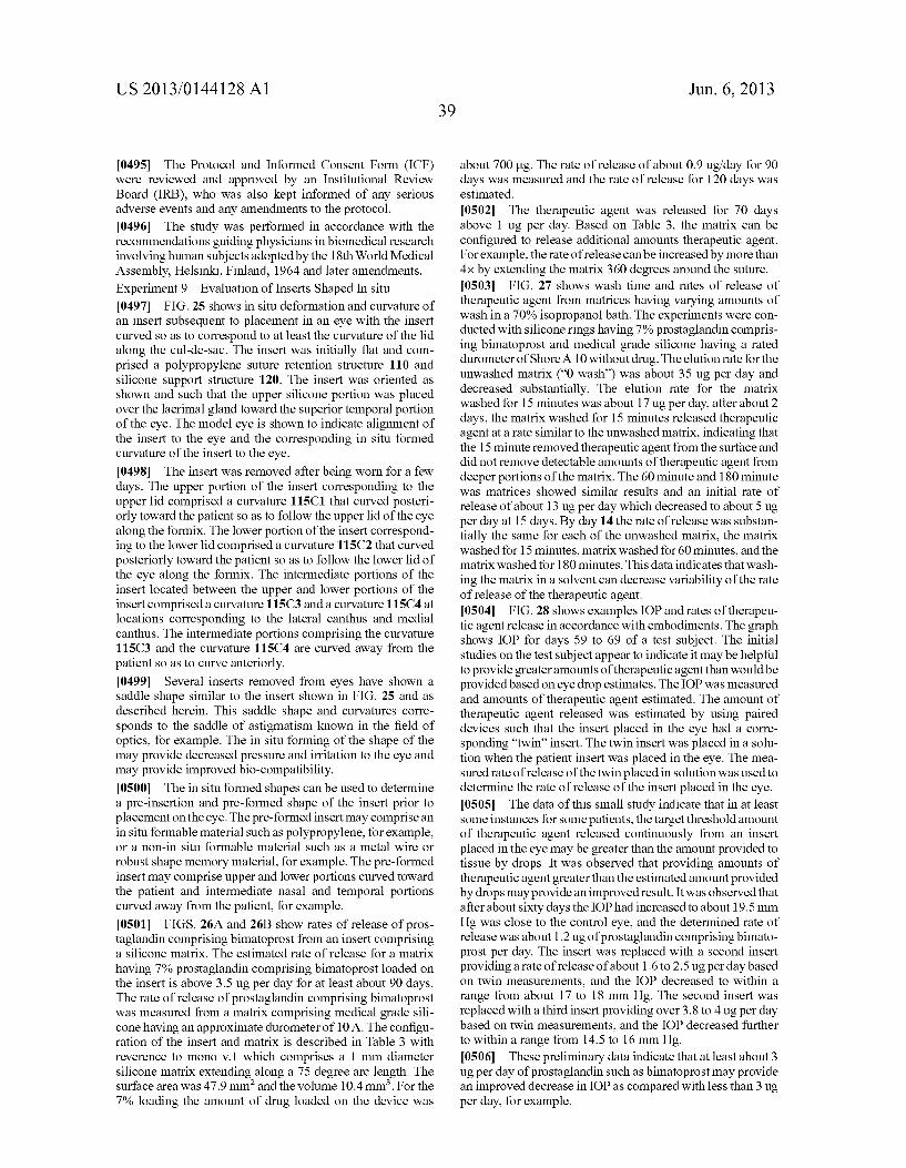
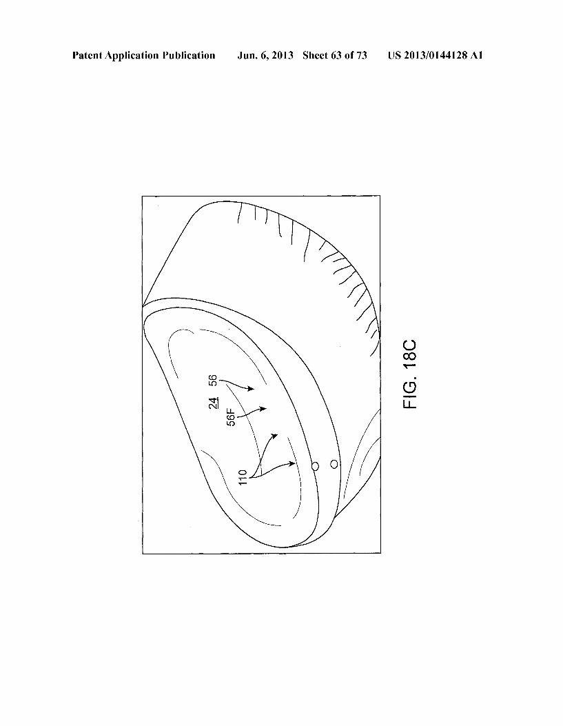
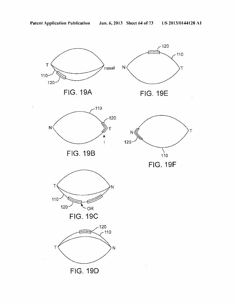
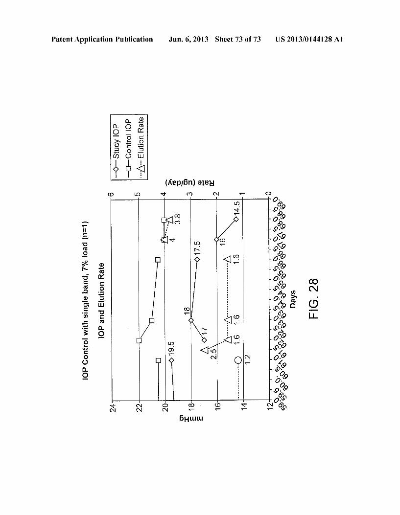
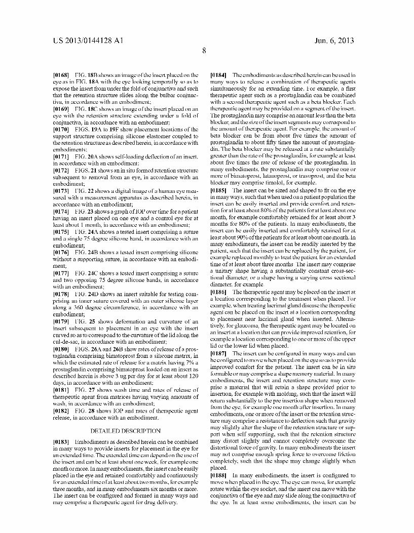
0168 FIG. 18B shows an image of the insert placed on the eye as in FIG. 18A with the eye looking temporally so as to expose the insert from under the fold of conjunctiva and such that the retention structure slides along the bulbar conjunc tiva, in accordance with an embodiment; 0169 FIG. 18C shows an image of the insert placed on an eye with the retention structure extending under a fold of conjunctiva, in accordance with an embodiment; (0170 FIGS. 19A to 19F show placement locations of the Support structure comprising silicone elastomer coupled to the retention structure as described herein, inaccordance with embodiments; 0171 FIG. 20A shows self-loading deflection of an insert, in accordance with an embodiment; 0172 FIGS. 21 shows an in situ formed retention structure Subsequent to removal from an eye, in accordance with an embodiment; 0173 FIG.22 shows a digital image of a human eye mea Sured with a measurement apparatus as described herein, in accordance with an embodiment; 0.174 FIG. 23 shows a graph of IOP over time for a patient having an insert placed on one eye and a control eye for at least about 1 month, in accordance with an embodiment; 0175 FIG. 24A shows a tested insert comprising a suture and a single 75 degree silicone band, in accordance with an embodiment; 0176 FIG.24B shows a tested insert comprising silicone without a Supporting Suture, in accordance with an embodi ment, 0177 FIG.24C shows a tested insert comprising a suture and two opposing 75 degree silicone bands, in accordance with an embodiment; 0.178 FIG.24D shows an insert suitable for testing com prising an inner Suture covered with an outer silicone layer along a 360 degree circumference, in accordance with an embodiment; 0179 FIG. 25 shows deformation and curvature of an insert Subsequent to placement in an eye with the insert curved so as to correspond to the curvature of the lid along the cul-de-sac, in accordance with an embodiment; 0180 FIGS. 26A and 26B show rates of release of a pros taglandin comprising bimatoprost from a silicone matrix, in which the estimated rate of release for a matrix having 7% a prostaglandin comprising bimatoprost loaded on an insert as described herein is above 3 ug per day for at least about 120 days, in accordance with an embodiment; 0181 FIG. 27 shows wash time and rates of release of therapeutic agent from matrices having varying amounts of wash, in accordance with an embodiment; 0182 FIG. 28 shows IOP and rates of therapeutic agent release, in accordance with an embodiment.
DETAILED DESCRIPTION
0183 Embodiments as described herein can be combined in many ways to provide inserts for placement in the eye for an extended time. The extended time can depend on the use of the insert and can be at least about one week, for example one month or more. In many embodiments, the insert can be easily placed in the eye and retained comfortably and continuously for an extended time of at least about two months, for example three months, and in many embodiments six months or more. The insert can be configured and formed in many ways and may comprise a therapeutic agent for drug delivery.
Jun. 6, 2013
0.184 The embodiments as described herein can be used in many ways to release a combination of therapeutic agents simultaneously for an extending time. For example, a first therapeutic agent such as a prostaglandin can be combined with a second therapeutic agent Such as a beta blocker. Each therapeutic agent may be provided on a segment of the insert. The prostaglandin may comprise an amountless than the beta blocker, and the size of the insert segments may correspond to the amount of therapeutic agent. For example, the amount of beta blocker can be from about five times the amount of prostaglandin to about fifty times the amount of prostaglan din. The beta blocker may be released at a rate substantially greater than the rate of the prostaglandin, for example at least about five times the rate of release of the prostaglandin. In many embodiments, the prostaglandin may comprise one or more of bimatoprost, latanoprost, or travoprost, and the beta blocker may comprise timolol, for example. 0185. The insert can be sized and shaped to fit on the eye in many ways, such that when used on a patient population the insert can be easily inserted and provide comfort and reten tion for at least about 80% of the patients for at least about one month, for example comfortably retained for at least about 3 months for 80% of the patients. In many embodiments, the insert can be easily inserted and comfortably retained for at least about 90% of the patients for at least about one month. In many embodiments, the insert can be readily inserted by the patient, such that the insert can be replaced by the patient, for example replaced monthly to treat the patient for an extended time of at least about three months. The insert may comprise a unitary shape having a substantially constant cross-sec tional diameter, or a shape having a varying cross sectional diameter, for example. 0186 The therapeutic agent may be placed on the insert at a location corresponding to the treatment when placed. For example, when treating lacrimal gland disease the therapeutic agent can be placed on the insert at a location corresponding to placement near lacrimal gland when inserted. Alterna tively, for glaucoma, the therapeutic agent may be located on an insert at a location that can provide improved retention, for example a location corresponding to one or more of the upper lid or the lower lid when placed. 0187. The insert can be configured in many ways and can be configured to move when placed on the eye so as to provide improved comfort for the patient. The insert can be in situ formable or may comprise a shape memory material. In many embodiments, the insert and retention structure may com prise a material that will retain a shape provided prior to insertion, for example with molding, Such that the insert will return substantially to the pre insertion shape when removed from the eye, for example one month after insertion. In many embodiments, one or more of the insert or the retention struc ture may comprise a resistance to deflection Such that gravity may slightly alter the shape of the retention structure or Sup port when self supporting, such that the retention structure may distort slightly and cannot completely overcome the distortional force of gravity. In many embodiments the insert may not comprise enough spring force to overcome friction completely, such that the shape may change slightly when placed. 0188 In many embodiments, the insert is configured to move when placed in the eye. The eye can move, for example rotate within the eye socket, and the insert can move with the conjunctiva of the eye and may slide along the conjunctiva of the eye. In at least Some embodiments, the insert can be
US 2013/0144128A1
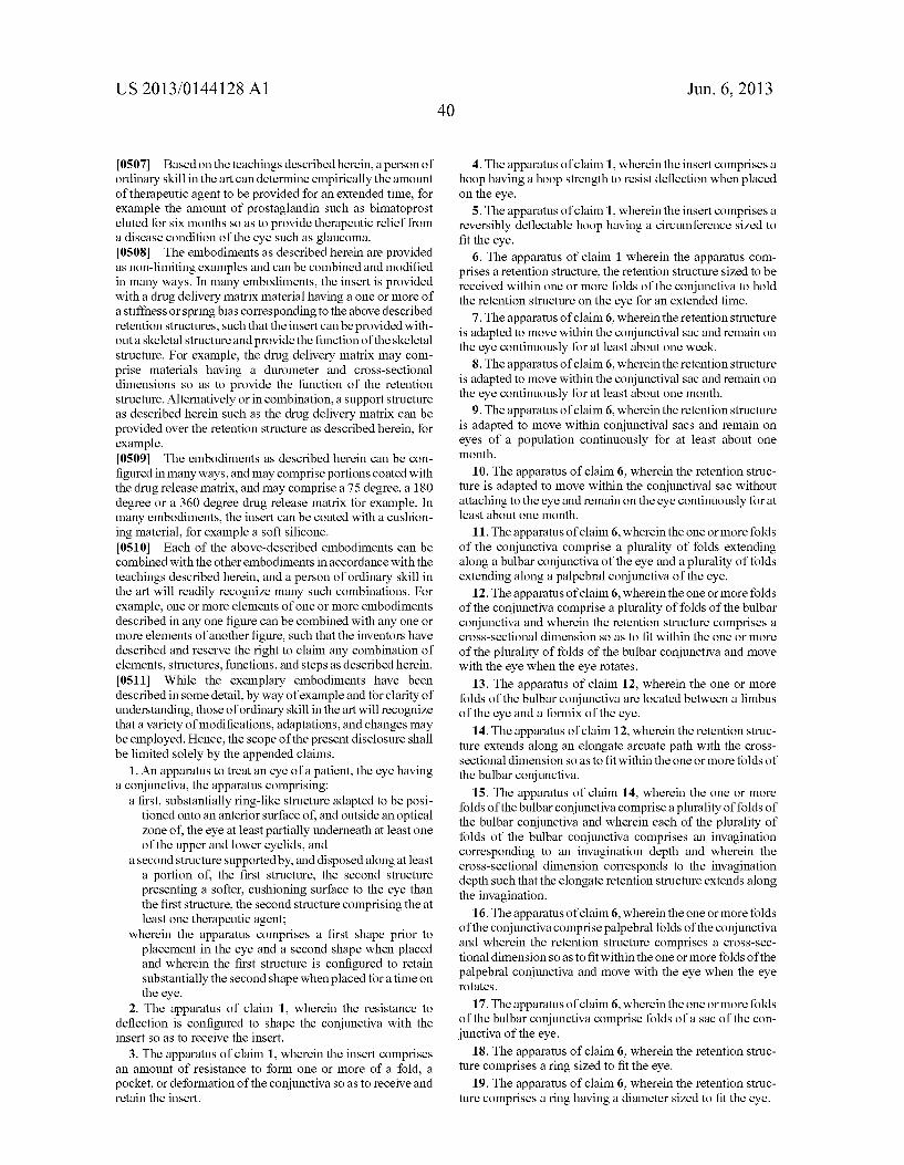
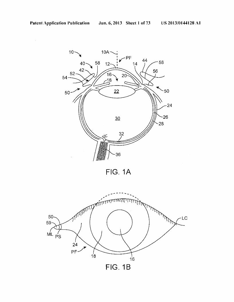
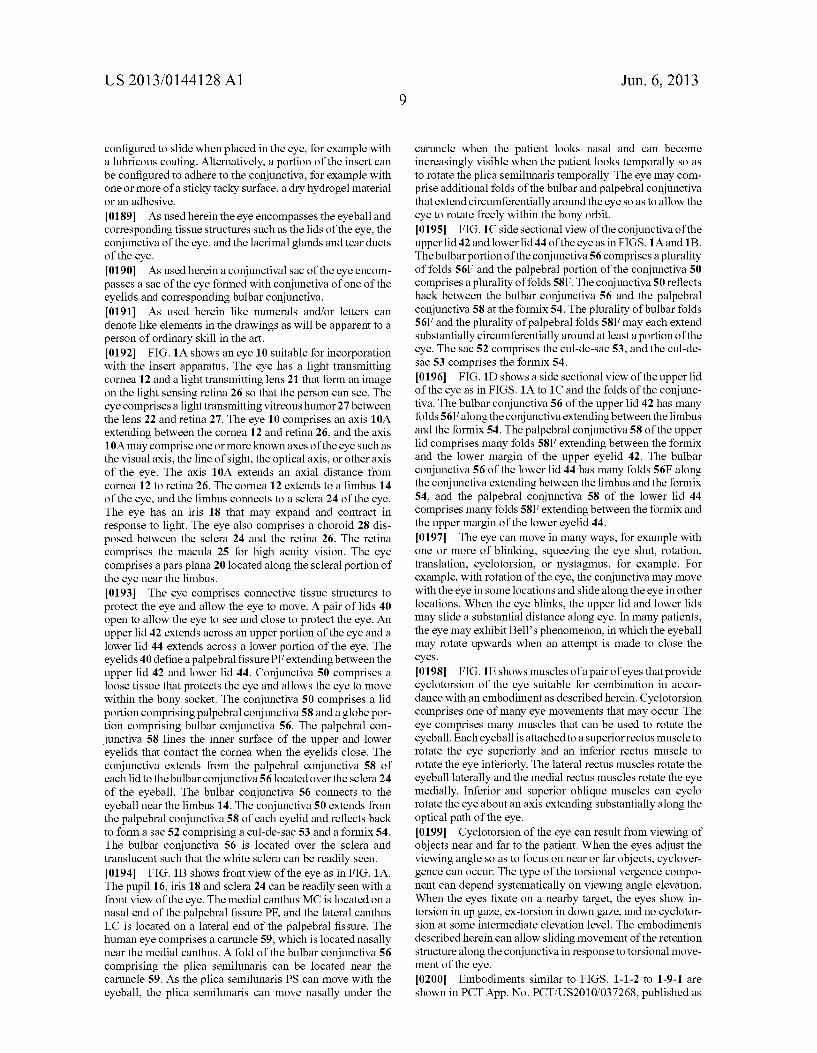
configured to slide when placed in the eye, for example with a lubricous coating. Alternatively, a portion of the insert can be configured to adhere to the conjunctiva, for example with one or more of a sticky tacky Surface, a dry hydrogel material or an adhesive. 0189 As used herein the eye encompasses the eyeball and corresponding tissue structures such as the lids of the eye, the conjunctiva of the eye, and the lacrimal glands and tear ducts of the eye. 0190. As used herein a conjunctival sac of the eye encom passes a sac of the eye formed with conjunctiva of one of the eyelids and corresponding bulbar conjunctiva. 0191 As used herein like numerals and/or letters can denote like elements in the drawings as will be apparent to a person of ordinary skill in the art. 0.192 FIG. 1A shows an eye 10 suitable for incorporation with the insert apparatus. The eye has a light transmitting cornea 12 and a light transmitting lens 21 that form an image on the light sensing retina 26 so that the person can see. The eye comprises a light transmitting vitreous humor 27 between the lens 22 and retina 27. The eye 10 comprises an axis 10A extending between the cornea 12 and retina 26, and the axis 10A may comprise one or more known axes of the eye such as the visual axis, the line of sight, the optical axis, or other axis of the eye. The axis 10A extends an axial distance from cornea 12 to retina 26. The cornea 12 extends to a limbus 14 of the eye, and the limbus connects to a sclera 24 of the eye. The eye has an iris 18 that may expand and contract in response to light. The eye also comprises a choroid 28 dis posed between the sclera 24 and the retina 26. The retina comprises the macula 25 for high acuity vision. The eye comprises a pars plana 20 located along the Scleral portion of the eye near the limbus. 0193 The eye comprises connective tissue structures to protect the eye and allow the eye to move. A pair of lids 40 open to allow the eye to see and close to protect the eye. An upper lid 42 extends across an upper portion of the eye and a lower lid 44 extends across a lower portion of the eye. The eyelids 40 define a palpebral fissure PF extending between the upper lid 42 and lower lid 44. Conjunctiva 50 comprises a loose tissue that protects the eye and allows the eye to move within the bony socket. The conjunctiva 50 comprises a lid portion comprising palpebral conjunctiva 58 and a globe por tion comprising bulbar conjunctiva 56. The palpebral con junctiva 58 lines the inner surface of the upper and lower eyelids that contact the cornea when the eyelids close. The conjunctiva extends from the palpebral conjunctiva 58 of each lid to the bulbar conjunctiva 56 located over the sclera 24 of the eyeball. The bulbar conjunctiva 56 connects to the eyeball near the limbus 14. The conjunctiva 50 extends from the palpebral conjunctiva 58 of each eyelid and reflects back to form a sac 52 comprising a cul-de-sac 53 and a formix54. The bulbar conjunctiva 56 is located over the sclera and translucent Such that the white Sclera can be readily seen. (0194 FIG. 1B shows front view of the eye as in FIG. 1A. The pupil 16, iris 18 and sclera 24 can be readily seen with a front view of the eye. The medial canthus MC is located on a nasal end of the palpebral fissure PF, and the lateral canthus LC is located on a lateral end of the palpebral fissure. The human eye comprises a caruncle 59, which is located nasally near the medial canthus. A fold of the bulbar conjunctiva 56 comprising the plica semilunaris can be located near the caruncle 59. As the plica semilunaris PS can move with the eyeball, the plica semilunaris can move nasally under the
Jun. 6, 2013
caruncle when the patient looks nasal and can become increasingly visible when the patient looks temporally so as to rotate the plica semilunaris temporally. The eye may com prise additional folds of the bulbar and palpebral conjunctiva that extend circumferentially around the eye so as to allow the eye to rotate freely within the bony orbit. (0195 FIG. 1C side sectional view of the conjunctiva of the upper lid 42 and lower lid 44 of the eye as in FIGS. 1A and 1B. The bulbarportion of the conjunctiva 56 comprises a plurality of folds 56F and the palpebral portion of the conjunctiva 50 comprises a plurality offolds 58F. The conjunctiva 50 reflects back between the bulbar conjunctiva 56 and the palpebral conjunctiva 58 at the formix54. The plurality of bulbar folds 56F and the plurality of palpebral folds 58F may each extend substantially circumferentially around at least a portion of the eye. The sac 52 comprises the cul-de-sac 53, and the cul-de sac 53 comprises the formix 54. 0.196 FIG. 1D shows a side sectional view of the upper lid of the eye as in FIGS. 1A to 1C and the folds of the conjunc tiva. The bulbar conjunctiva 56 of the upper lid 42 has many folds 56F along the conjunctiva extending between the limbus and the formix 54. The palpebral conjunctiva 58 of the upper lid comprises many folds 58F extending between the formix and the lower margin of the upper eyelid 42. The bulbar conjunctiva 56 of the lower lid 44 has many folds 56F along the conjunctiva extending between the limbus and the formix 54, and the palpebral conjunctiva 58 of the lower lid 44 comprises many folds 58F extending between the formix and the upper margin of the lower eyelid 44. 0197) The eye can move in many ways, for example with one or more of blinking, Squeezing the eye shut, rotation, translation, cyclotorsion, or nystagmus, for example. For example, with rotation of the eye, the conjunctiva may move with the eye in some locations and slide along the eye in other locations. When the eye blinks, the upper lid and lower lids may slide a substantial distance along eye. In many patients, the eye may exhibit Bell's phenomenon, in which the eyeball may rotate upwards when an attempt is made to close the eyes. 0198 FIG.1E shows muscles of a pair of eyes that provide cyclotorsion of the eye suitable for combination in accor dance with an embodiment as described herein. Cyclotorsion comprises one of many eye movements that may occur. The eye comprises many muscles that can be used to rotate the eyeball. Each eyeball is attached to a superior rectus muscle to rotate the eye Superiorly and an inferior rectus muscle to rotate the eye inferiorly. The lateral rectus muscles rotate the eyeball laterally and the medial rectus muscles rotate the eye medially. Inferior and Superior oblique muscles can cyclo rotate the eye about an axis extending Substantially along the optical path of the eye. 0199 Cyclotorsion of the eye can result from viewing of objects near and far to the patient. When the eyes adjust the viewing angle so as to focus on near or far objects, cyclover gence can occur. The type of the torsional vergence compo nent can depend systematically on viewing angle elevation. When the eyes fixate on a nearby target, the eyes show in torsion in up gaze, ex-torsion in down gaze, and no cyclotor sion at some intermediate elevation level. The embodiments described herein can allow sliding movement of the retention structure along the conjunctiva in response to torsional move ment of the eye. 0200 Embodiments similar to FIGS. 1-1-2 to 1-9-1 are shown in PCT App. No. PCT/US2010/037268, published as
US 2013/0144128A1
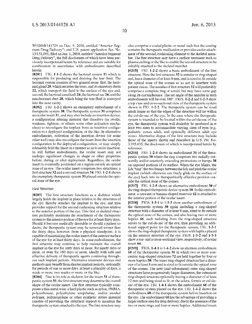
WO2010/141729 on Dec. 9, 2010, entitled “Anterior Seg ment Drug Delivery': and U.S. patent application Ser. No. 13/151,001, filed on Jun. 1, 2010, entitled “Anterior Segment Drug Delivery', the full disclosures of which have been pre viously incorporated herein by reference and are suitable for combination in accordance with embodiments described herein. 0201 FIG. 1-1-2 shows the lacrimal system 11 which is responsible for producing and draining the tear fluid. The lacrimal system consists of two general areas: first, the lacri mal gland 20, which secretes the tears, and its excretory ducts 22, which transport the fluid to the surface of the eye and, second, the lacrimal canaliculi 24, the lacrimal sac 26, and the nasolacrimal duct 28, which bring the tear fluid is conveyed into the nose cavity. 0202 FIG. 1-2-1 shows an exemplary embodiment of a therapeutic system 30. The therapeutic system 30 comprises an ocular insert 31, and may also include an insertion device, a configuration altering material that dissolves (or Swells, weakens, tightens, or effects some other activation mecha nism) to reconfigure the implant from an insertion configu ration to a deployed configuration, or the like. In alternative embodiments, activation of the insertion device (or some other tool) may also reconfigure the insert from the insertion configuration to the deployed configuration, or may simply releasably hold the insert in a manner So as to assist insertion. In still further embodiments, the ocular insert may not undergo significant changes in shape or other properties before, during, or after deployment. Regardless, the ocular insert is eventually positioned on a region outside an optical Zone of an eye. The ocular insert comprises two structures: a first structure 32 and a second structure 34. FIG. 1-2-1 shows the exemplary therapeutic system 30 placed outside the opti cal Zone of the eye.
First Structure
0203 The first structure functions as a skeleton which largely holds the implant in place relative to the structures of the eye, thereby attaches the implant to the eye, and thus provides Support for the second cushioning structure relative to the anterior portion of the eye. This first or skeletal struc ture preferably maintains the attachment of the therapeutic system to the anteriorportion of the eye for at least thirty days. Should it become medically desirable or should a patient so desire, the therapeutic system may be removed sooner than the thirty days; however, from a physical standpoint, it is capable of maintaining the ocularinsert of the anterior Surface of the eye for at least thirty days. In some embodiments, the first structure may continue to help maintain the overall implant in the eye for sixty days or more, for ninety days or more, or even for 180 days or more, ideally with safe and effective delivery of therapeutic agents continuing through out Such implant periods. Alternative treatment devices and methods may benefit from shorter implant periods, optionally for periods of one or more days, at least a plurality of days, a week or more, two weeks or more, or the like. 0204. Due to its role as skeleton for the insert 31 of thera peutic system 30, the first structure may determine the overall shape of the ocular insert. The first structure typically com prises a thin metal wire, a hard plastic such as nylon, PMMA, polycarbonate, polyethylene terepthalate, and/or another polymer, polypropylene or other synthetic Suture material capable of providing the structural Support to maintain the therapeutic system attached to the eye. The first structure may
Jun. 6, 2013
also comprise a coated plastic or metal Such that the coating contains the therapeutic medication or provides easier attach ment of the second, cushioning element to the skeletal mem ber. The first structure may have a surface treatment such as plasma etching or the like to enable the second structure to be suitably attached to the skeletal member. 0205 FIG. 1-2-2 shows a basic embodiment of the first structure. Here the first structure 32 is annular or ring-shaped and, has a diameter of at least 8 mm, and is sized to fit outside the optical Zone of the cornea so as not to interfere with patient vision. The annulus of first structure 32 will preferably comprise a complete ring or toroid, but may have some gap along its circumference. The arc angle of the annulus in Such embodiments will be over 180°. FIGS. 1-2-2 and 1-2-3 Show a top view and cross-sectional view of the therapeutic system shown in FIG. 1-2-2. The therapeutic system can be sized much larger so that the edges of the structure will lie within the cul-de-sac of the eye. In the case where the therapeutic system is intended to be located within the cul-de-sac of the eye, the therapeutic system will desirably be produced in at least two sizes to accommodate varying sizes of eyes (e.g. pediatric versus adult, and optionally different adult eye sizes). Alternative shapes of the first structure may include those of the inserts shown and described in U.S. Pat. No. 3.995,635, the disclosure of which is incorporated herein by reference.
0206 FIG. 1-2-4 shows an embodiment 36 of the thera peutic system 30 where the ring comprises two radially out wardly and/or anteriorly extending protrusions or bumps 38 on opposed portions of its surface. When the eye blinks, the lids “trap' the two bumps between the lids and push the ocular implant (which otherwise can freely glide on the surface of the eye) back into its therapeutically effective position out side the optical Zone of the cornea. 0207 FIG. 1-2-5 shows an alternative embodiment 30 of the ring-shaped therapeutic device system30. In this embodi ment, a crescent or banana-shaped reservoir 62 is attached to the inferior portion of the ocular insert. 0208 FIGS. 1-3-1 to 1-3-3 show another embodiment of the therapeutic system 30 again including a ring-shaped structure with a diameter of at least 8 mm, sized to fit outside the optical Zone of the cornea, and also having two or more haptics 66, each radiating from the ring-shaped structure across to the cul-de-sac of the eye, thus providing an addi tional support point for the therapeutic system. FIG. 1-3-1 shows the ring-shaped therapeutic system with haptics placed on the anterior structure of the eye. FIGS. 1-3-2 and 1-3-3 show a top- and a cross-sectional view, respectively, of ocular insert 64.
0209 FIGS. 1-4-1 to 1-4-2 show an alternate embodiment 68 of the therapeutic system 30 in which two or more con centric ring-shaped structures 72 are held together by four or more haptics 50. The inner ring-shaped structure has a diam eter of at least 8 mm and is sized to fit outside the optical Zone of the cornea. The next (and Subsequent) outer ring-shaped structures have progressively larger diameters, the outermost ring-shaped structure optionally having a diameter of at least 12 mm and being sized to fit on the Sclera, formix or cul-de sac of the eye. FIG. 1-4-1 shows the embodiment 68 of the therapeutic system placed on the eye. FIG. 1-4-2 shows the embodiment 68 of the therapeutic system before insertion on the eye. The embodiment 68 has the advantage of providing a larger Surface area for drug delivery, due to the presence of the two or more rings and four or more haptics. Additional insert
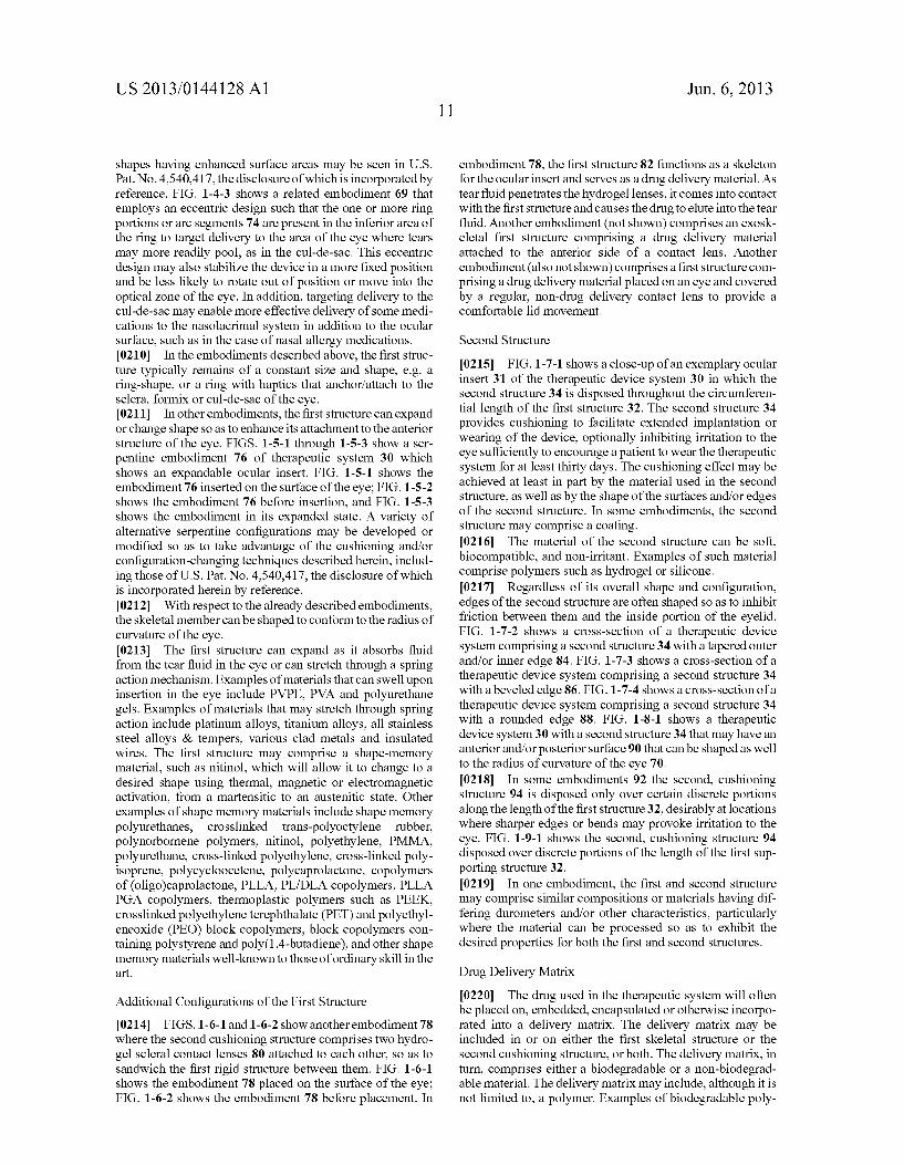
US 2013/0144128A1
shapes having enhanced Surface areas may be seen in U.S. Pat. No. 4,540,417, the disclosure of which is incorporated by reference. FIG. 1-4-3 shows a related embodiment 69 that employs an eccentric design Such that the one or more ring portions or arc segments 74 are present in the inferior area of the ring to target delivery to the area of the eye where tears may more readily pool, as in the cul-de-sac. This eccentric design may also stabilize the device in a more fixed position and be less likely to rotate out of position or move into the optical Zone of the eye. In addition, targeting delivery to the cul-de-sac may enable more effective delivery of some medi cations to the nasolacrimal system in addition to the ocular Surface, such as in the case of nasal allergy medications. 0210. In the embodiments described above, the first struc ture typically remains of a constant size and shape, e.g. a ring-shape, or a ring with haptics that anchor/attach to the Sclera, formix or cul-de-sac of the eye. 0211. In other embodiments, the first structure can expand or change shape so as to enhance its attachment to the anterior structure of the eye. FIGS. 1-5-1 through 1-5-3 show a ser pentine embodiment 76 of therapeutic system 30 which shows an expandable ocular insert. FIG. 1-5-1 shows the embodiment 76 inserted on the surface of the eye; FIG. 1-5-2 shows the embodiment 76 before insertion, and FIG. 1-5-3 shows the embodiment in its expanded state. A variety of alternative serpentine configurations may be developed or modified so as to take advantage of the cushioning and/or configuration-changing techniques described herein, includ ing those of U.S. Pat. No. 4,540,417, the disclosure of which is incorporated herein by reference. 0212. With respect to the already described embodiments, the skeletal member can be shaped to conform to the radius of curvature of the eye. 0213. The first structure can expand as it absorbs fluid from the tear fluid in the eye or can stretch through a spring action mechanism. Examples of materials that can Swell upon insertion in the eye include PVPE, PVA and polyurethane gels. Examples of materials that may stretch through spring action include platinum alloys, titanium alloys, all stainless steel alloys & tempers, various clad metals and insulated wires. The first structure may comprise a shape-memory material. Such as initinol, which will allow it to change to a desired shape using thermal, magnetic or electromagnetic activation, from a martensitic to an austenitic state. Other examples of shape memory materials include shape memory polyurethanes, crosslinked trans-polyoctylene rubber, polynorbornene polymers, nitinol, polyethylene, PMMA, polyurethane, cross-linked polyethylene, cross-linked poly isoprene, polycycloocetene, polycaprolactone, copolymers of (oligo)caprolactone, PLLA, PL/DLA copolymers, PLLA PGA copolymers, thermoplastic polymers such as PEEK, crosslinked polyethylene terephthalate (PET) and polyethyl eneoxide (PEO) block copolymers, block copolymers con taining polystyrene and poly(1,4-butadiene), and other shape memory materials well-known to those of ordinary skill in the art.
Additional Configurations of the First Structure 0214 FIGS. 1-6-1 and 1-6-2 show another embodiment 78 where the second cushioning structure comprises two hydro gel Scleral contact lenses 80 attached to each other, so as to sandwich the first rigid structure between them. FIG. 1-6-1 shows the embodiment 78 placed on the surface of the eye; FIG. 1-6-2 shows the embodiment 78 before placement. In
Jun. 6, 2013
embodiment 78, the first structure 82 functions as a skeleton for the ocular insert and serves as a drug delivery material. As tear fluid penetrates the hydrogel lenses, it comes into contact with the first structure and causes the drug to elute into the tear fluid. Another embodiment (not shown) comprises an exosk eletal first structure comprising a drug delivery material attached to the anterior side of a contact lens. Another embodiment (also not shown) comprises a first structure com prising a drug delivery material placed on an eye and covered by a regular, non-drug delivery contact lens to provide a comfortable lid movement.
Second Structure
0215 FIG. 1-7-1 shows a close-up of an exemplary ocular insert 31 of the therapeutic device system 30 in which the second structure 34 is disposed throughout the circumferen tial length of the first structure 32. The second structure 34 provides cushioning to facilitate extended implantation or wearing of the device, optionally inhibiting irritation to the eye sufficiently to encourage a patient to wear the therapeutic system for at least thirty days. The cushioning effect may be achieved at least in part by the material used in the second structure, as well as by the shape of the Surfaces and/or edges of the second structure. In some embodiments, the second structure may comprise a coating. 0216. The material of the second structure can be soft, biocompatible, and non-irritant. Examples of Such material comprise polymers such as hydrogel or silicone. 0217 Regardless of its overall shape and configuration, edges of the second structure are often shaped so as to inhibit friction between them and the inside portion of the eyelid. FIG. 1-7-2 shows a cross-section of a therapeutic device system comprising a second structure 34 with a tapered outer and/or inner edge 84. FIG. 1-7-3 shows a cross-section of a therapeutic device system comprising a second structure 34 with a beveled edge 86. FIG. 1-7-4 shows a cross-section of a therapeutic device system comprising a second structure 34 with a rounded edge 88. FIG. 1-8-1 shows a therapeutic device system 30 with a second structure 34 that may have an anterior and/or posterior surface 90 that can be shaped as well to the radius of curvature of the eye 70. 0218. In some embodiments 92 the second, cushioning structure 94 is disposed only over certain discrete portions along the length of the first structure 32, desirably at locations where sharper edges or bends may provoke irritation to the eye. FIG. 1-9-1 shows the second, cushioning structure 94 disposed over discrete portions of the length of the first Sup porting structure 32. 0219. In one embodiment, the first and second structure may comprise similar compositions or materials having dif fering durometers and/or other characteristics, particularly where the material can be processed so as to exhibit the desired properties for both the first and second structures.
Drug Delivery Matrix
0220. The drug used in the therapeutic system will often be placed on, embedded, encapsulated or otherwise incorpo rated into a delivery matrix. The delivery matrix may be included in or on either the first skeletal structure or the second cushioning structure, or both. The delivery matrix, in turn, comprises either a biodegradable or a non-biodegrad able material. The delivery matrix may include, although it is not limited to, a polymer. Examples of biodegradable poly
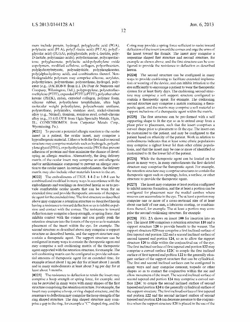
US 2013/0144128A1
mers include protein, hydrogel, polyglycolic acid (PGA), polylactic acid (PLA), poly(L-lactic acid) (PLLA), poly(L- glycolic acid) (PLGA), polyglycolide, poly-L-lactide, poly D-lactide, poly(amino acids), polydioxanone, polycaprolac tone, polygluconate, polylactic acid-polyethylene oxide copolymers, modified cellulose, collagen, polyorthoesters, polyhydroxybutyrate, polyanhydride, polyphosphoester, poly(alpha-hydroxy acid), and combinations thereof. Non biodegradable polymers may comprise silicone, acrylates, polyethylenes, polyurethane, polyurethane, hydrogel, poly ester (e.g., DACRONR) from E.I. Du Pont de Nemours and Company, Wilmington, Del.), polypropylene, polytetrafluo roethylene (PTFE), expanded PTFE (ePTFE), polyetherether ketone (PEEK), nylon, extruded collagen, polymer foam, silicone rubber, polyethylene terephthalate, ultra high molecular weight polyethylene, polycarbonate urethane, polyurethane, polyimides, stainless steel, nickel-titanium alloy (e.g., Nitinol), titanium, stainless steel, cobalt-chrome alloy (e.g., ELGILOY(R) from Elgin Specialty Metals, Elgin, Ill.: CONICHROME(R) from Carpenter Metals Corp., Wyomissing, Pa.). 0221) To prevent a potential allergic reaction to the ocular insert in a patient, the ocular insert, may comprise a hypoallergenic material. Either or both the first and/or second structure may comprise materials such as hydrogels, polyeth ylene glycol (PEG), or polyethylene oxide (PEO) that prevent adhesion of proteins and thus minimize the chance of devel oping an allergic reaction. Alternatively, the drug delivery matrix of the ocular insert may comprise an anti-allergenic and/or antihistaminic compound to prevent an allergic reac tion to the ocular insert. In certain embodiments, the delivery matrix may also include other materials known in the art. 0222. The embodiments of FIGS. 1-1-2 to 1-9-1 can be combined and modified in many ways in accordance with the embodiments and teachings as described herein so as to pro vide comfortable ocular inserts that can be worn for an extended time and provide therapeutic amounts of therapeu tic agent for the extended time. The first structure as described above may comprise a retention structure as described herein having a resistance to inward deflection so as to inhibit expul sion and contact with the cornea. The resistance to inward deflection may comprise a hoop strength, or spring force, that inhibits contact with the cornea and can gently push the retention structure into the formix of the eye so as to maintain placement of the insert within the eye, for example. The second structure as described above may comprise a Support structure as described herein, and the Support structure may contain a therapeutic agent. The Support structure can be configured in many ways to contain the therapeutic agent and may comprise a soft cushioning matrix of the therapeutic agent Supported with the retention structure, for example. The Soft cushioning matrix can be configured to provide Substan tial amounts of therapeutic agent for an extended time, for example at least about 1 lug per day for at least about 1 month and in many embodiments at least about 3 ug per day for at least about 3 months.
0223) The resistance to deflection to retain the insert may comprise a hoop strength or spring force, for example, and can be provided in many ways with many shapes of the first structure comprising the retention structure. For example, the insert may comprise a hoop, or ring shaped structure, and the resistance to deflection may comprise the hoop strength of the ring shaped structure. The ring shaped structure may com prise a gap in the ring, for example a “C” shaped ring, and the
Jun. 6, 2013
C-ring may provide a spring force Sufficient to resist inward deflection of the insert toward the cornea and urge the arms of the insert toward the formix. The insert may comprise a serpentine shaped first structure and second structure, for example as shown above, and the first structure can be con figured to provide the resistance to deflection as described herein.
0224. The second structure can be configured in many ways to provide cushioning to facilitate extended implanta tion or wearing of the device, and can inhibit irritation to the eye sufficiently to encourage a patient to wear the therapeutic system for at least thirty days. The cushioning second struc ture may comprise a soft Support structure configured to contain a therapeutic agent, for example. The cushioning second structure may comprise a matrix containing a thera peutic agent, and the matrix may comprise a soft material to Support inclusions of a therapeutic agent within the matrix. 0225. The first structure can be pre-formed with a self Supporting shape to fit the eye so as to extend away from a plane prior to placement, Such that the insert comprises a curved shape prior to placement to fit the eye. The insert can be customized to the patient, and may be configured to the patient based on ethnicity of the patient. Work in relation to embodiments indicates that at least some ethnic populations may comprise a tighter lower lid than other ethnic popula tions, and that the insert may be one or more of identified or customized to fit the lower lid of the patient. 0226. While the therapeutic agent can be loaded on the insert in many ways, in many embodiments the first skeletal structure may comprise the therapeutic agent. For example, the retention structure may comprise structures to contain the therapeutic agent such as openings, holes, a surface, or other structure to provide the therapeutic agent. 0227. The insert may comprise at least portion configured to inhibit mucous formation, and the at least a portion can be configured for placement near the medial canthus where mucous can accumulate in the eye. The at least a portion may comprise one or more of a cross-sectional size of at least about one half of one mm, a lubricous coating, or combina tions thereof, for example. The at least a portion may com prise the second cushioning structure, for example. 0228 FIG. 2A shows an insert 100 for insertion into an eye. The insert 100 comprises a retention structure 110 and a support structure 120 to provide benefit to the wearer. The support structure 120 may comprise a first inclined surface of first tapered end portion 122 and a second inclined surface of second tapered end portion 124, so as to allow the Support structure 120 to slide within the conjunctival sac of the eye. The first inclined surface of first tapered end portion 122 may comprise a curved surface 122C to couple the first inclined surface of first tapered end poftion 122 to the generally elon gate Surface of the Support structure that can be cylindrical. The first and second inclined surfaces can be configured in many ways and may comprise crescent, torpedo or other shapes so as to contact the conjunctiva within the sac and allow movement of the insert. The second inclined surface of second tapered end portion 124 may comprise a curved Sur face 124C to couple the second inclined surface of second tapered end portion 124 to the generally cylindrical surface of the support structure. The first inclined surface of first tapered end portion 122 and the second inclined surface of second tapered end portion 124 can decrease pressure to the conjunc tiva when the support structure 120 is placed in the sac of the
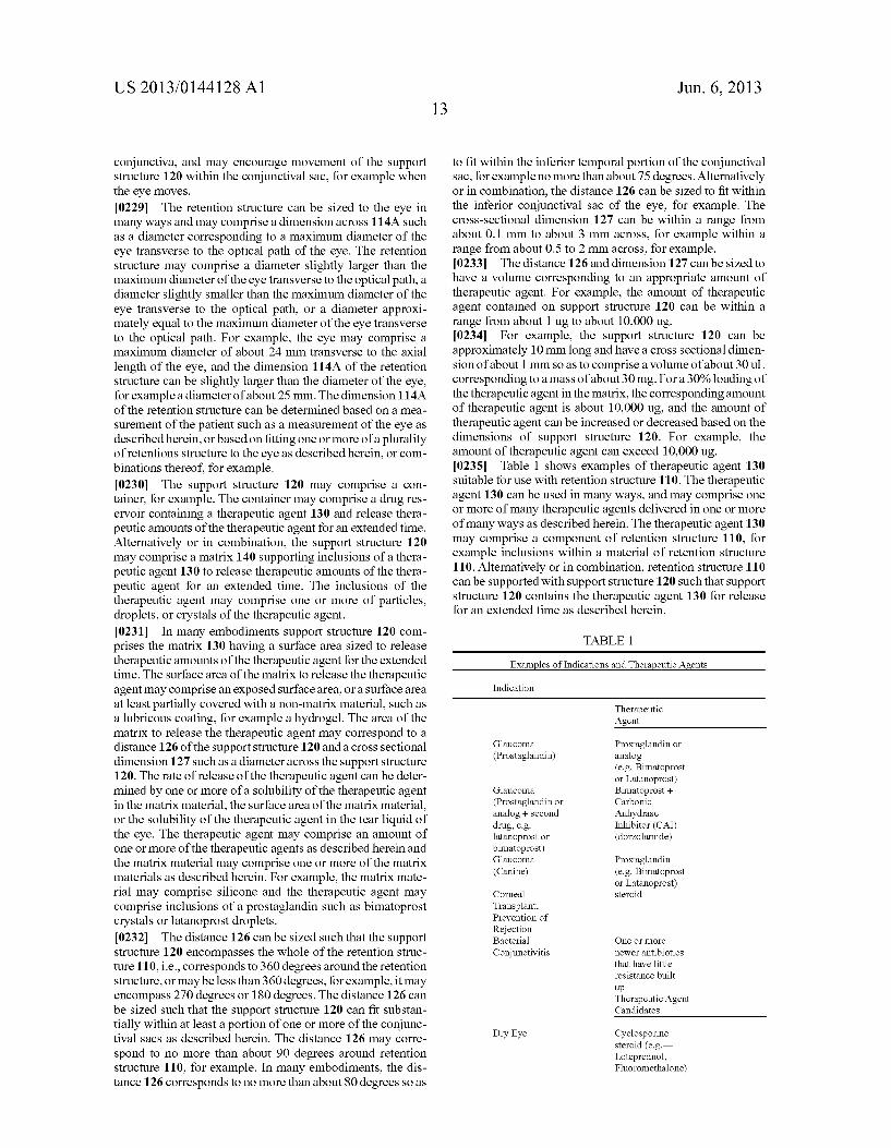
US 2013/0144128A1
conjunctiva, and may encourage movement of the Support structure 120 within the conjunctival sac, for example when the eye moves. 0229. The retention structure can be sized to the eye in many ways and may comprise a dimension across 114A Such as a diameter corresponding to a maximum diameter of the eye transverse to the optical path of the eye. The retention structure may comprise a diameter slightly larger than the maximum diameter of the eye transverse to the optical path, a diameter slightly smaller than the maximum diameter of the eye transverse to the optical path, or a diameter approxi mately equal to the maximum diameter of the eye transverse to the optical path. For example, the eye may comprise a maximum diameter of about 24 mm transverse to the axial length of the eye, and the dimension 114A of the retention structure can be slightly larger than the diameter of the eye, for example a diameter of about 25 mm. The dimension 114A of the retention structure can be determined based on a mea Surement of the patient Such as a measurement of the eye as described herein, or based on fitting one or more of a plurality of retentions structure to the eye as described herein, or com binations thereof, for example. 0230. The support structure 120 may comprise a con
tainer, for example. The container may comprise a drug res ervoir containing a therapeutic agent 130 and release thera peutic amounts of the therapeutic agent for an extended time. Alternatively or in combination, the support structure 120 may comprise a matrix 140 supporting inclusions of a thera peutic agent 130 to release therapeutic amounts of the thera peutic agent for an extended time. The inclusions of the therapeutic agent may comprise one or more of particles, droplets, or crystals of the therapeutic agent. 0231. In many embodiments support structure 120 com prises the matrix 130 having a surface area sized to release therapeutic amounts of the therapeutic agent for the extended time. The surface area of the matrix to release the therapeutic agent may comprise an exposed Surface area, or a surface area at least partially covered with a non-matrix material. Such as a lubricous coating, for example a hydrogel. The area of the matrix to release the therapeutic agent may correspond to a distance 126 of the support structure 120 and a cross sectional dimension 127 Such as a diameteracross the Support structure 120. The rate of release of the therapeutic agent can be deter mined by one or more of a solubility of the therapeutic agent in the matrix material, the Surface area of the matrix material, or the solubility of the therapeutic agent in the tear liquid of the eye. The therapeutic agent may comprise an amount of one or more of the therapeutic agents as described herein and the matrix material may comprise one or more of the matrix materials as described herein. For example, the matrix mate rial may comprise silicone and the therapeutic agent may comprise inclusions of a prostaglandin Such as bimatoprost crystals or latanoprost droplets. 0232. The distance 126 can be sized such that the support structure 120 encompasses the whole of the retention struc ture 110, i.e., corresponds to 360 degrees around the retention structure, or may be less than 360 degrees, for example, it may encompass 270 degrees or 180 degrees. The distance 126 can be sized such that the support structure 120 can fit substan tially within at least a portion of one or more of the conjunc tival sacs as described herein. The distance 126 may corre spond to no more than about 90 degrees around retention structure 110, for example. In many embodiments, the dis tance 126 corresponds to no more than about 80 degrees so as
Jun. 6, 2013
to fit within the inferior temporal portion of the conjunctival sac, for example no more than about 75 degrees. Alternatively or in combination, the distance 126 can be sized to fit within the inferior conjunctival sac of the eye, for example. The cross-sectional dimension 127 can be within a range from about 0.1 mm to about 3 mm across, for example within a range from about 0.5 to 2 mm across, for example. 0233. The distance 126 and dimension 127 can be sized to have a Volume corresponding to an appropriate amount of therapeutic agent. For example, the amount of therapeutic agent contained on Support structure 120 can be within a range from about 1 ug to about 10,000 ug. 0234 For example, the support structure 120 can be approximately 10 mm long and have a cross sectional dimen sion of about 1 mm so as to comprise a volume of about 30 ul corresponding to a mass of about 30 mg. For a 30% loading of the therapeutic agent in the matrix, the corresponding amount of therapeutic agent is about 10,000 ug, and the amount of therapeutic agent can be increased or decreased based on the dimensions of support structure 120. For example, the amount of therapeutic agent can exceed 10,000 ug. 0235 Table 1 shows examples of therapeutic agent 130 suitable for use with retention structure 110. The therapeutic agent 130 can be used in many ways, and may comprise one or more of many therapeutic agents delivered in one or more of many ways as described herein. The therapeutic agent 130 may comprise a component of retention structure 110, for example inclusions within a material of retention structure 110. Alternatively or in combination, retention structure 110 can be supported with support structure 120 such that support structure 120 contains the therapeutic agent 130 for release for an extended time as described herein.
TABLE 1
Examples of Indications and Therapeutic Agents
Indication
Therapeutic Agent
Glaucoma Prostaglandin or (Prostaglandin) analog
(e.g. Bimatoprost or Latanoprost)
Glaucoma Bimatoprost + (Prostaglandin or analog + second drug, e.g. latanoprost or bimatoprost) Glaucoma (Canine)
Corneal Transplant, Prevention of Rejection Bacterial Conjunctivitis
Dry Eye
Carbonic Anhydrase Inhibitor (CAI) (dorzolamide)
Prostaglandin (e.g. Bimatoprost or Latanoprost) steroid
One or more newer antibiotics that have little resistance built up Therapeutic Agent Candidates
Cyclosporine steroid (e.g.— Loteprednol, Fluoromethalone)
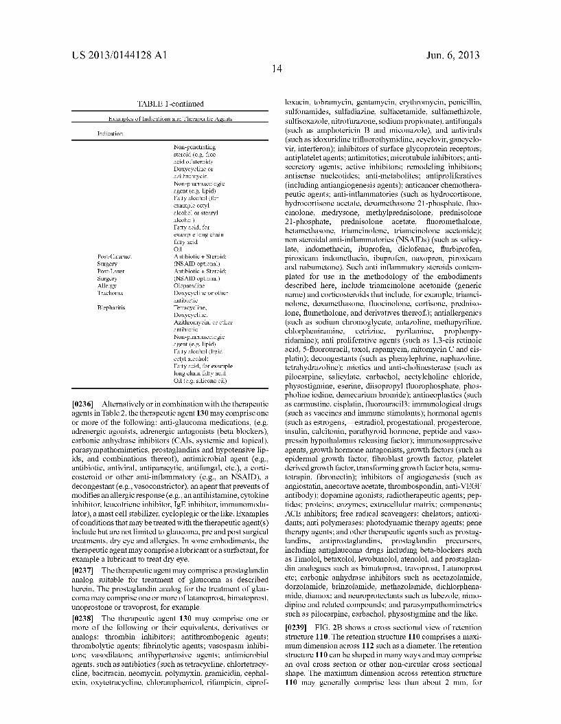
US 2013/0144128A1
TABLE 1-continued
Examples of Indications and Therapeutic Agents
Indication
Non-penetrating steroid (e.g. free acid of steroid) Doxycycline or azithromycin Non-pharmacologic agent (e.g. lipid) Fatty alcohol (for example cetyl alcohol or stearyl alcohol) Fatty acid, for example long chain fatty acid Oil Antibiotic + Steroid: (NSAID optional) Antibiotic + Steroid: (NSAID optional) Olopatadine Doxycycline or other antibiotic Tetracycline, Doxycycline, Azithromycin, or other antibiotic Non-pharmacologic agent (e.g. lipid) Fatty alcohol (lipid cetyl alcohol) Fatty acid, for example long chain fatty acid Oil (e.g. silicone oil)
Post-Cataract Surgery Post-Laser Surgery Allergy Trachoma
Blepharitis
0236 Alternatively or in combination with the therapeutic agents in Table 2, the therapeutic agent 130 may comprise one or more of the following: anti-glaucoma medications, (e.g. adrenergic agonists, adrenergic antagonists (beta blockers), carbonic anhydrase inhibitors (CAIs, systemic and topical), parasympathomimetics, prostaglandins and hypotensive lip ids, and combinations thereof), antimicrobial agent (e.g., antibiotic, antiviral, antiparacytic, antifungal, etc.), a corti costeroid or other anti-inflammatory (e.g., an NSAID), a decongestant (e.g., vasoconstrictor), an agent that prevents of modifies an allergic response (e.g., an antihistamine, cytokine inhibitor, leucotriene inhibitor, IgE inhibitor, immunomodu lator), a mast cell stabilizer, cycloplegic or the like. Examples of conditions that may be treated with the therapeutic agent(s) include but are not limited to glaucoma, pre and post Surgical treatments, dry eye and allergies. In some embodiments, the therapeutic agent may comprise a lubricantora Surfactant, for example a lubricant to treat dry eye. 0237 The therapeutic agent may comprise a prostaglandin analog Suitable for treatment of glaucoma as described herein. The prostaglandin analog for the treatment of glau coma may comprise one or more of latanoprost, bimatoprost, unoprostone or travoprost, for example. 0238. The therapeutic agent 130 may comprise one or more of the following or their equivalents, derivatives or analogs: thrombin inhibitors; antithrombogenic agents; thrombolytic agents; fibrinolytic agents; vasospasm inhibi tors; vasodilators; antihypertensive agents; antimicrobial agents, such as antibiotics (such as tetracycline, chlortetracy cline, bacitracin, neomycin, polymyxin, gramicidin, cephal exin, oxytetracycline, chloramphenicol, rifampicin, ciprof
14 Jun. 6, 2013
loxacin, tobramycin, gentamycin, erythromycin, penicillin, Sulfonamides, Sulfadiazine, Sulfacetamide, Sulfamethizole, Sulfisoxazole, nitrofuraZone, Sodium propionate), antifungals (such as amphotericin B and miconazole), and antivirals (such as idoxuridine trifluorothymidine, acyclovir, gancyclo Vir, interferon); inhibitors of Surface glycoprotein receptors; antiplatelet agents; antimitotics; microtubule inhibitors; anti secretory agents; active inhibitors; remodeling inhibitors; antisense nucleotides; anti-metabolites; antiproliferatives (including antiangiogenesis agents); anticancer chemothera peutic agents; anti-inflammatories (such as hydrocortisone, hydrocortisone acetate, dexamethasone 21-phosphate, fluo cinolone, medrysone, methylprednisolone, prednisolone 21-phosphate, prednisolone acetate, fluoromethalone, betamethasone, triamcinolone, triamcinolone acetonide); non steroidal anti-inflammatories (NSAIDs) (such as salicy late, indomethacin, ibuprofen, diclofenac, flurbiprofen, piroXicam indomethacin, ibuprofen, naxopren, piroxicam and nabumetone). Such anti inflammatory steroids contem plated for use in the methodology of the embodiments described here, include triamcinolone acetonide (generic name) and corticosteroids that include, for example, triamci nolone, dexamethasone, fluocinolone, cortisone, predniso lone, flumetholone, and derivatives thereof); antiallergenics (such as Sodium chromoglycate, antazoline, methapyriline, chlorpheniramine, cetrizine, pyrilamine, prophenpy ridamine); anti proliferative agents (such as 1.3-cis retinoic acid, 5-fluorouracil, taxol, rapamycin, mitomycin C and cis platin); decongestants (such as phenylephrine, naphazoline, tetrahydrazoline); miotics and anti-cholinesterase (such as pilocarpine, Salicylate, carbachol, acetylcholine chloride, physostigmine, eserine, diisopropyl fluorophosphate, phos pholine iodine, demecarium bromide); antineoplastics (such as carmustine, cisplatin, fluorouracil3; immunological drugs (such as vaccines and immune stimulants); hormonal agents (such as estrogens, estradiol, progestational, progesterone, insulin, calcitonin, parathyroid hormone, peptide and vaso pressin hypothalamus releasing factor); immunosuppressive agents, growth hormone antagonists, growth factors (such as epidermal growth factor, fibroblast growth factor, platelet derived growth factor, transforming growth factor beta, Soma totrapin, fibronectin); inhibitors of angiogenesis (such as angiostatin, anecortave acetate, thrombospondin, anti-VEGF antibody); dopamine agonists; radiotherapeutic agents; pep tides; proteins; enzymes; extracellular matrix; components; ACE inhibitors; free radical scavengers; chelators; antioxi dants; anti polymerases; photodynamic therapy agents; gene therapy agents; and other therapeutic agents such as prostag landins, antiprostaglandins, prostaglandin precursors, including antiglaucoma drugs including beta-blockers such as Timolol, betaxolol, levobunolol, atenolol, and prostaglan din analogues such as bimatoprost, travoprost, Latanoprost etc.; carbonic anhydrase inhibitors such as acetazolamide, dorzolamide, brinzolamide, methazolamide, dichlorphena mide, diamox, and neuroprotectants such as lubezole, nimo dipine and related compounds; and parasympathomimetrics Such as pilocarpine, carbachol, physostigmine and the like. 0239 FIG. 2B shows a cross sectional view of retention structure 110. The retention structure 110 comprises a maxi mum dimension across 112 Such as a diameter. The retention structure 110 can be shaped in many ways and may comprise an oval cross section or other non-circular cross sectional shape. The maximum dimension across retention structure 110 may generally comprise less than about 2 mm, for
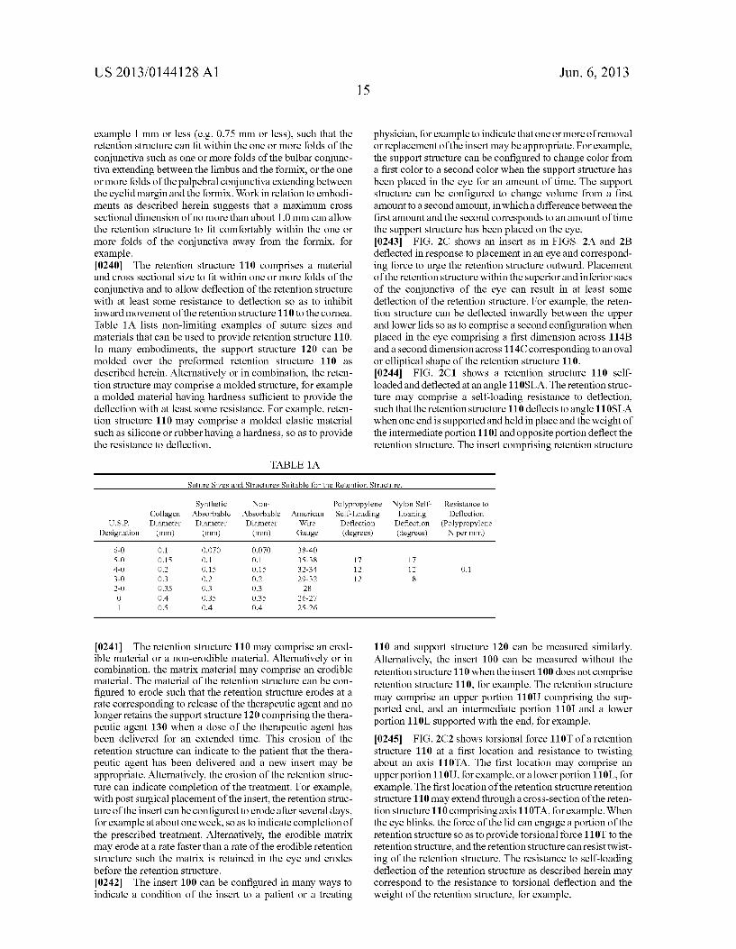
US 2013/0144128A1
example 1 mm or less (e.g. 0.75 mm or less). Such that the retention structure can fit within the one or more folds of the conjunctiva Such as one or more folds of the bulbar conjunc tiva extending between the limbus and the formix, or the one or more folds of the palpebral conjunctiva extending between the eyelid margin and the formix. Workin relation to embodi ments as described herein suggests that a maximum cross sectional dimension of no more than about 1.0 mm can allow the retention structure to fit comfortably within the one or more folds of the conjunctiva away from the formix, for example. 0240. The retention structure 110 comprises a material and cross sectional size to fit within one or more folds of the conjunctiva and to allow deflection of the retention structure with at least some resistance to deflection so as to inhibit inward movement of the retention structure 110 to the cornea. Table 1A lists non-limiting examples of Suture sizes and materials that can be used to provide retention structure 110. In many embodiments, the support structure 120 can be molded over the preformed retention structure 110 as described herein. Alternatively or in combination, the reten tion structure may comprise a molded structure, for example a molded material having hardness Sufficient to provide the deflection with at least some resistance. For example, reten tion structure 110 may comprise a molded elastic material Such as silicone or rubber having a hardness, so as to provide the resistance to deflection.
TABLE 1A
15 Jun. 6, 2013
physician, for example to indicate that one or more of removal or replacement of the insert may be appropriate. For example, the Support structure can be configured to change color from a first color to a second color when the Support structure has been placed in the eye for an amount of time. The Support structure can be configured to change Volume from a first amount to a second amount, in which a difference between the first amount and the second corresponds to an amount of time the Support structure has been placed on the eye. 0243 FIG. 2C shows an insert as in FIGS. 2A and 2B deflected in response to placement in an eye and correspond ing force to urge the retention structure outward. Placement of the retention structure within the superior and inferior sacs of the conjunctiva of the eye can result in at least some deflection of the retention structure. For example, the reten tion structure can be deflected inwardly between the upper and lower lids so as to comprise a second configuration when placed in the eye comprising a first dimension across 114B and a second dimension across 114C corresponding to an oval or elliptical shape of the retention structure 110. 0244 FIG. 2C1 shows a retention structure 110 self loaded and deflected at an angle 110SLA. The retention struc ture may comprise a self-loading resistance to deflection, such that the retention structure 110 deflects to angle 110SLA when one end is Supported and held in place and the weight of the intermediate portion 110I and opposite portion deflect the retention structure. The insert comprising retention structure
Suture Sizes and Structures Suitable for the Retention Structure.
Synthetic Non- Polypropylene Nylon Self- Resistance to Collagen Absorbable Absorbable American Self-Loading Loading Deflection
U.S.P. Diameter Diameter Diameter Wire Deflection Deflection (Polypropylene Designation (mm) (mm) (mm) Gauge (degrees) (degrees) N per mm)
6-O O.1 O.O70 O.O70 38-40 S-O O.15 O.1 O.1 35-38 17 17 4-0 O.2 O.15 O.15 32-34 12 12 O.1 3-0 O.3 O.2 O.2 29-32 12 8 2-0 O.35 O.3 O.3 28 O 0.4 O.35 O3S 26-27 1 O.S 0.4 0.4 25-26
0241 The retention structure 110 may comprise an erod ible material or a non-erodible material. Alternatively or in combination, the matrix material may comprise an erodible material. The material of the retention structure can be con figured to erode Such that the retention structure erodes at a rate corresponding to release of the therapeutic agent and no longer retains the Support structure 120 comprising the thera peutic agent 130 when a dose of the therapeutic agent has been delivered for an extended time. This erosion of the retention structure can indicate to the patient that the thera peutic agent has been delivered and a new insert may be appropriate. Alternatively, the erosion of the retention struc ture can indicate completion of the treatment. For example, with post Surgical placement of the insert, the retention struc ture of the insert can be configured to erode after several days, for example at about one week, so as to indicate completion of the prescribed treatment. Alternatively, the erodible matrix may erode at a rate faster than a rate of the erodible retention structure such the matrix is retained in the eye and erodes before the retention structure. 0242. The insert 100 can be configured in many ways to indicate a condition of the insert to a patient or a treating
110 and support structure 120 can be measured similarly. Alternatively, the insert 100 can be measured without the retention structure 110 when the insert 100 does not comprise retention structure 110, for example. The retention structure may comprise an upper portion 110U comprising the Sup ported end, and an intermediate portion 110I and a lower portion 110L supported with the end, for example. 0245 FIG. 2C2 shows torsional force 110T of a retention structure 110 at a first location and resistance to twisting about an axis 110TA. The first location may comprise an upper portion 110U, for example, or a lower portion 110L, for example. The first location of the retention structure retention structure 110 may extend through a cross-section of the reten tion structure 110 comprising axis 110TA, for example. When the eye blinks, the force of the lid can engage a portion of the retention structure so as to provide torsional force 110T to the retention structure, and the retention structure can resist twist ing of the retention structure. The resistance to self-loading deflection of the retention structure as described herein may correspond to the resistance to torsional deflection and the weight of the retention structure, for example.
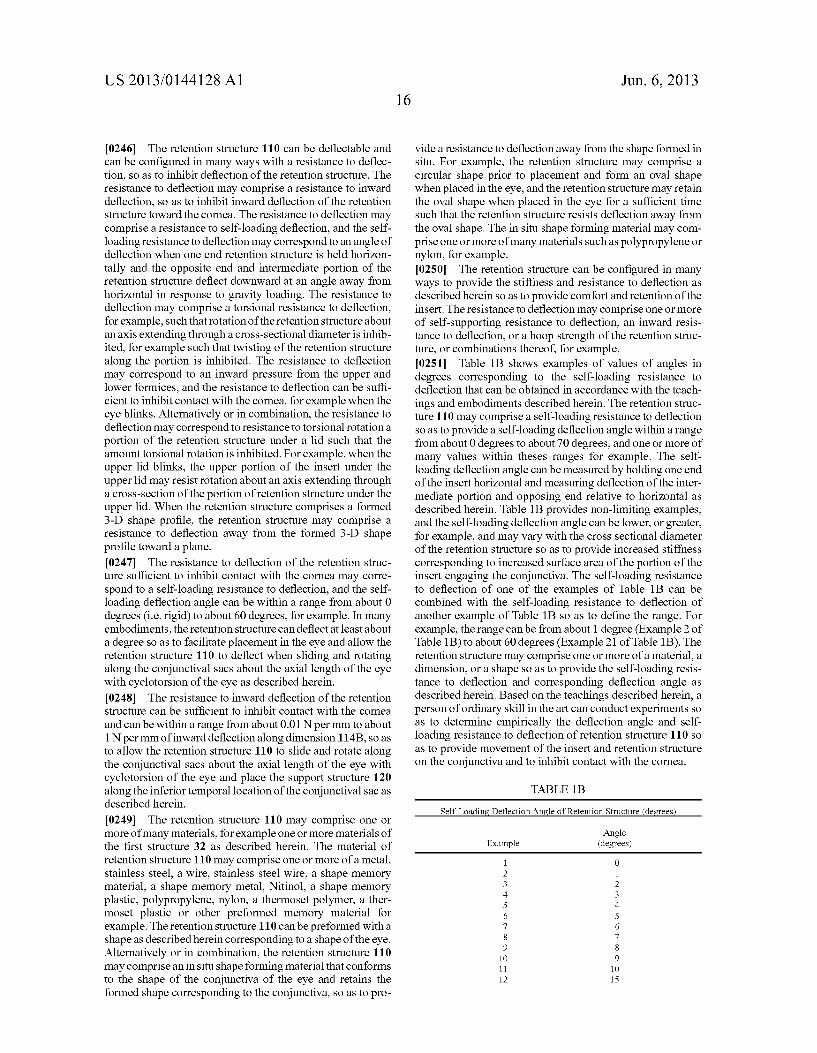
US 2013/0144128A1
0246 The retention structure 110 can be deflectable and can be configured in many ways with a resistance to deflec tion, so as to inhibit deflection of the retention structure. The resistance to deflection may comprise a resistance to inward deflection, so as to inhibit inward deflection of the retention structure toward the cornea. The resistance to deflection may comprise a resistance to self-loading deflection, and the self loading resistance to deflection may correspond to an angle of deflection when one end retention structure is held horizon tally and the opposite end and intermediate portion of the retention structure deflect downward at an angle away from horizontal in response to gravity loading. The resistance to deflection may comprise a torsional resistance to deflection, for example, such that rotation of the retention structure about an axis extending through a cross-sectional diameter is inhib ited, for example such that twisting of the retention structure along the portion is inhibited. The resistance to deflection may correspond to an inward pressure from the upper and lower formices, and the resistance to deflection can be suffi cient to inhibit contact with the cornea, for example when the eye blinks. Alternatively or in combination, the resistance to deflection may correspond to resistance to torsional rotation a portion of the retention structure under a lid such that the amount torsional rotation is inhibited. For example, when the upper lid blinks, the upper portion of the insert under the upper lid may resist rotation about an axis extending through a cross-section of the portion of retention structure under the upper lid. When the retention structure comprises a formed 3-D shape profile, the retention structure may comprise a resistance to deflection away from the formed 3-D shape profile toward a plane. 0247 The resistance to deflection of the retention struc ture sufficient to inhibit contact with the cornea may corre spond to a self-loading resistance to deflection, and the self loading deflection angle can be within a range from about 0 degrees (i.e. rigid) to about 60 degrees, for example. In many embodiments, the retention structure can deflectat least about a degree so as to facilitate placement in the eye and allow the retention structure 110 to deflect when sliding and rotating along the conjunctival sacs about the axial length of the eye with cyclotorsion of the eye as described herein. 0248. The resistance to inward deflection of the retention structure can be sufficient to inhibit contact with the cornea and can be within a range from about 0.01 N per mm to about 1N per mm of inward deflection along dimension 114B, so as to allow the retention structure 110 to slide and rotate along the conjunctival sacs about the axial length of the eye with cyclotorsion of the eye and place the support structure 120 along the inferior temporal location of the conjunctival sac as described herein.
0249. The retention structure 110 may comprise one or more of many materials, for example one or more materials of the first structure 32 as described herein. The material of retention structure 110 may comprise one or more of a metal, stainless steel, a wire, stainless Steel wire, a shape memory material, a shape memory metal, Nitinol, a shape memory plastic, polypropylene, nylon, a thermoset polymer, a ther moset plastic or other preformed memory material for example. The retention structure 110 can be preformed with a shape as described herein corresponding to a shape of the eye. Alternatively or in combination, the retention structure 110 may comprise an in situ shape forming material that conforms to the shape of the conjunctiva of the eye and retains the formed shape corresponding to the conjunctiva, so as to pro
Jun. 6, 2013
vide a resistance to deflection away from the shape formed in situ. For example, the retention structure may comprise a circular shape prior to placement and form an oval shape when placed in the eye, and the retention structure may retain the oval shape when placed in the eye for a sufficient time such that the retention structure resists deflection away from the oval shape. The in situ shape forming material may com prise one or more of many materials such as polypropylene or nylon, for example. 0250. The retention structure can be configured in many ways to provide the stiffness and resistance to deflection as described herein so as to provide comfort and retention of the insert. The resistance to deflection may comprise one or more of self-supporting resistance to deflection, an inward resis tance to deflection, or a hoop strength of the retention struc ture, or combinations thereof, for example. 0251 Table 1B shows examples of values of angles in degrees corresponding to the self-loading resistance to deflection that can be obtained in accordance with the teach ings and embodiments described herein. The retention struc ture 110 may comprise a self-loading resistance to deflection So as to provide a self-loading deflection angle within a range from about 0 degrees to about 70 degrees, and one or more of many values within theses ranges for example. The self loading deflection angle can be measured by holding one end of the insert horizontal and measuring deflection of the inter mediate portion and opposing end relative to horizontal as described herein. Table 1B provides non-limiting examples, and the self-loading deflection angle can be lower, or greater, for example, and may vary with the cross sectional diameter of the retention structure so as to provide increased stiffness corresponding to increased Surface area of the portion of the insert engaging the conjunctiva. The self-loading resistance to deflection of one of the examples of Table 1B can be combined with the self-loading resistance to deflection of another example of Table 1B so as to define the range. For example, the range can be from about 1 degree (Example 2 of Table 1B) to about 60 degrees (Example 21 of Table 1B). The retention structure may comprise one or more of a material, a dimension, or a shape so as to provide the self-loading resis tance to deflection and corresponding deflection angle as described herein. Based on the teachings described herein, a person of ordinary skill in the art can conduct experiments so as to determine empirically the deflection angle and self loading resistance to deflection of retention structure 110 so as to provide movement of the insert and retention structure on the conjunctiva and to inhibit contact with the cornea.
TABLE 1B
Self-Loading Deflection Angle of Retention Structure (degrees
Angle Example (degrees)
1 O 2 1 3 2 4 3 5 4 6 5 7 6 8 7 9 8 10 9 11 10 12 15
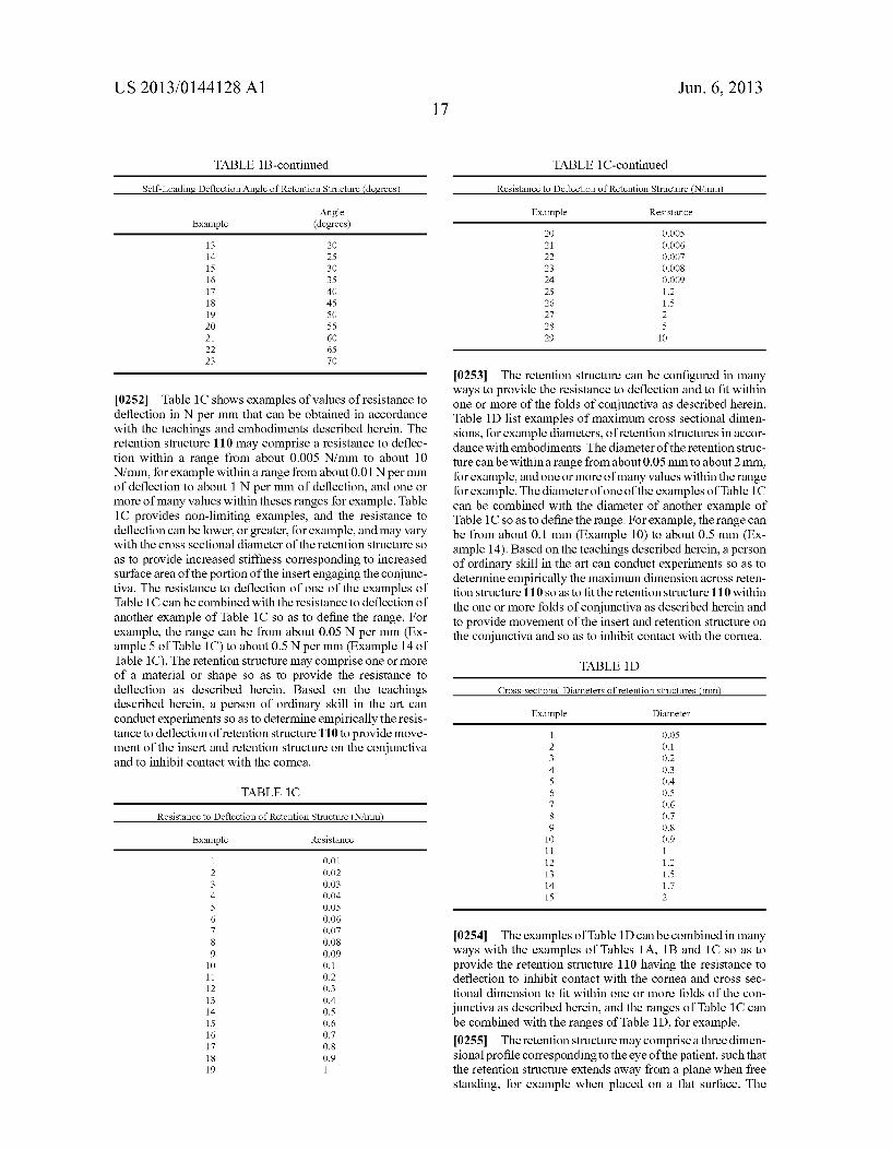
US 2013/0144128A1
TABLE 1 B-continued
Self-Loading Deflection Angle of Retention Structure (degrees
Angle Example (degrees)
13 2O 14 25 15 30 16 35 17 40 18 45 19 50 2O 55 21 60 22 65 23 70
0252 Table 1 C shows examples of values of resistance to deflection in N per mm that can be obtained in accordance with the teachings and embodiments described herein. The retention structure 110 may comprise a resistance to deflec tion within a range from about 0.005 N/mm to about 10 N/mm. for example within a range from about 0.01 N per mm of deflection to about 1 N per mm of deflection, and one or more of many values within theses ranges for example. Table 1C provides non-limiting examples, and the resistance to deflection can be lower, or greater, for example, and may vary with the cross sectional diameter of the retention structure so as to provide increased stiffness corresponding to increased Surface area of the portion of the insert engaging the conjunc tiva. The resistance to deflection of one of the examples of Table 1C can be combined with the resistance to deflection of another example of Table 1C so as to define the range. For example, the range can be from about 0.05 N per mm (Ex ample 5 of Table 1C) to about 0.5 N per mm (Example 14 of Table 1C). The retention structure may comprise one or more of a material or shape so as to provide the resistance to deflection as described herein. Based on the teachings described herein, a person of ordinary skill in the art can conduct experiments so as to determine empirically the resis tance to deflection of retention structure 110 to provide move ment of the insert and retention structure on the conjunctiva and to inhibit contact with the cornea.
TABLE 1C
Resistance to Deflection of Retention Structure (NImm
Example Resistance
1 O.O1 2 O.O2 3 O.O3 4 O.04 5 O.OS 6 O.O6 7 O.O7 8 O.08 9 O.09 10 O.1 11 O.2 12 O.3 13 0.4 14 O.S 15 O6 16 0.7 17 O.8 18 O.9 19 1
17 Jun. 6, 2013
TABLE 1 C-continued
Resistance to Deflection of Retention Structure (NImm
Example Resistance
2O O.OOS 21 O.OO6 22 O.OO7 23 O.OO8 24 O.OO9 25 1.2 26 1.5 27 2 28 5 29 10
0253) The retention structure can be configured in many ways to provide the resistance to deflection and to fit within one or more of the folds of conjunctiva as described herein. Table 1D list examples of maximum cross sectional dimen sions, for example diameters, of retention structures in accor dance with embodiments. The diameter of the retention struc ture can be within a range from about 0.05 mm to about 2 mm, for example, and one or more of many values within the range for example. The diameter of one of the examples of Table 1C can be combined with the diameter of another example of Table 1 C so as to define the range. For example, the range can be from about 0.1 mm (Example 10) to about 0.5 mm (Ex ample 14). Based on the teachings described herein, a person of ordinary skill in the art can conduct experiments so as to determine empirically the maximum dimension across reten tion structure 110 so as to fit the retention structure 110 within the one or more folds of conjunctiva as described herein and to provide movement of the insert and retention structure on the conjunctiva and so as to inhibit contact with the cornea.
TABLE 1D
Cross-sectional Diameters of retention structures (mm
Example Diameter
O.OS O.1 O.2 O.3 0.4 O.S O6 0.7 O.8 O.9 1 1.2 1.5 1.7 2
1
0254 The examples of Table 1D can be combined in many ways with the examples of Tables 1A, 1B and 1C so as to provide the retention structure 110 having the resistance to deflection to inhibit contact with the cornea and cross sec tional dimension to fit within one or more folds of the con junctiva as described herein, and the ranges of Table 1C can be combined with the ranges of Table 1D, for example. 0255. The retention structure may comprise a three dimen sional profile corresponding to the eye of the patient, Such that the retention structure extends away from a plane when free standing, for example when placed on a flat surface. The
US 2013/0144128A1
examples of Tables 1A, 1B, 1C, and 1D can be combined with the preformed shape to provide a resistance to deflection Such that the retention structure extends away from a plane when placed on a flat surface and urges the portion of the retention structure placed under the lower lid toward the eyeball when the first portion of the retention structure is placed under the upper lid. Work in relation to embodiments also suggests that one or more of the resistance to deflection or the column strength can provide Sufficient force so as to transmit circum ferential torsional force from a first portion of the structure to a second portion of the structure, such that the first portion of the structure can urge the second portion of the structure. For example, the first portion comprising at least a portion of Support structure 120 may urge a second portion comprising at least a portion retention structure 110 circumferentially around the pupil of the eye with cyclotorsion of the eye. The retention structure 110 may comprise a molded preformed retention structure, for example a molded silicone elastomer having the three dimensional oval shape corresponding to the bulbar conjunctiva of the eye of the patient, and the three dimensional molded shape may comprise a resistance to deflection toward a plane similar to the sutures of Table 1C. For example, work in relation to embodiments Suggests that silicone elastomer having a cross-sectional diameter of within a range from about 0.5 mm to about 1.0 mm may have a resistance to deflection similar to a polypropylene Suture having a cross-sectional diameter within a range from about 0.1 mm to about 0.2 mm.
0256 FIG. 2D shows an insert having a preformed oval shape extending along a convex surface of an eye. Such that the ring extends away from a plane and resists deflection toward a plane. The insert can be configured to deflect away from a plane in many ways and can be bent at one or more locations so as to extend away from the plane, or may com prise one or more curved portions extending away from the plane with curvature corresponding to the eye so as to fit the eye of the patient with the one or more curved portions, or combinations thereof. The plane may correspond to a plane of the limbus 14. The convex surface of the eye may comprise one or more of a spherical Surface, a toric Surface, an elliptical Surface, a cylindrical Surface, a conical Surface, or combina tions thereof, corresponding to one or more of the Scleral surface or the bulbar conjunctival surface of the eye of patient. The insert 100 may comprise a three dimensional shape (hereinafter "3D) corresponding substantially to the shape of the insert when placed on the eye. The pre-formed shape of retention structure 110 prior to placement on the eye may comprise a substantially oval shape having an elevation pro file corresponding to the oval shape placed on a spherical surface corresponding to the eyeball of the patient. The sub stantially oval preformed shape may comprise a first maxi mum dimension across 114A1 in a first direction correspond ing to a Superior-inferior direction along the eyeball of the patient and a second maximum dimension across 114A2 along a second direction corresponding to a nasal-temporal direction along the eyeball of the patient. The first maximum dimension across 114A1 may correspond to a minor axis of an ellipse and the second dimension across 114A2 may cor respond to a major axis of an ellipse, although the generally oval shape may comprise one or more of many shapes such as lentoid, conic cross section, elliptical or other shape projected onto a spherical surface as described herein. The insert 100 may extend closer to the limbus 14 in along the Superior and inferiorportions than the nasal and temporal portions. As the
Jun. 6, 2013
eyeball may correspond to a substantially spherical Surface, the eyeball may comprise a radius of curvature Rb corre sponding to the spherical shape of the eyeball. Consequently, the nasal and temporal portions of the insert may extend away from a plane corresponding to the inferior and Superior por tions of the insert.
0257 FIG. 2E shows a side view of an insert as in FIG. 2D extending along nasal-temporal and anterior posterior direc tions. The anterior direction A, the posterior direction P, the nasal direction N, and the temporal direction T are each shown. The insert may comprise a preformed 3D shape cor responding to the radius Rb and the first dimension across 114A1 and the second dimension across 114A2, such that the lower portion of the insert is urged posteriorly toward the bulbar conjunctiva when the upper lid covers at least a portion of the insert. Alternatively or in combination, the insert may comprise a preformed 3D shape corresponding to the radius Rb and the first dimension across 114A1 and the second dimension across 114A2, such that the lower portion of the insert resists deflection anteriorly away the bulbar conjunc tiva when the upper lid covers at least a portion of the insert. This resistance to deflection can be provided with the insert preformed with the 3D profile corresponding to the radius Rb of the patient. The limbus 14 may correspond to a plane of the eye. The retention structure 110 may comprise a first pre formed Sag height 114S1 corresponding to an anterior-poste rior elevation distance from the limbus to the inferior and superior portions of the insert. The retention structure 110 may comprise a second preformed sag height 114S2 corre sponding to an anterior posterior elevation distance from the limbus to the nasal and temporal portions of the insert. The difference in the Sag heights may comprise a differential sag height 114DS and the differential sag height 114DS may correspond to an amount the retention structure deflects from a plane when the insert is placed on a flat surface. The Support structure 120 can be shaped similarly to the retention struc ture 110, such that the insert 100 comprises the three dimen sional shape corresponding to the eye of the patient. The retention structure 110 may comprise one or more of many shapes as described herein, and the corresponding Sag height profile extending around the insert can be determined based on the projection of the shape onto a spherical Surface having radius Rb corresponding to the eye of the patient. The reten tion structure 110 and the support structure 120 comprising the three dimensional shape profiles may comprise the resis tance to deflection as described herein.
0258. The insert 100 comprising the retention structure having the 3D shape profile may comprise a Surface to retain the insert. The Surface may be configured in one or more of many ways to retain the insert. The Surface may comprise a Sticky, tacky Surface to retain the insert within the one or more folds of the conjunctiva. The Sticky, tacky Surface may com prise a soft hydrophilic Surface, such as the Surface of a soft silicone elastomer. Alternatively or in combination, the Sur face may comprise a coating of hydrogel material as described herein, for example a substantially dry hydrogel material Such that the dry hydrogel material may stick to the one or more folds when placed and moisture drawn from the tissue or mucus contacting the hydrogel. For example, the hydrogel coating may extend along a portion of the insert corresponding to the lacrimal gland. Alternatively, the insert may comprise a lubricous coating to encourage movement of the insert with the eye, such that the 3D shape profile can slide along the conjunctiva and resist deformation when the eye
US 2013/0144128A1
moves. For example, the lubricous coating can be placed over the insert at locations corresponding to one or more of the lacrimal gland or the caruncle. The insert 100 comprising the 3D shape/profile as described herein may provide retention when substantially the entire surface of the insert 100 com prising the retention structure 110 and the support structure 120 are each coated with the lubricous coating as described herein, such that the insert 100 can slide along the sacs of the conjunctiva and seat the insert with movement of the insert along the conjunctiva. For example, the insert 100 may be dip-coated in a hydrogel, and the hydrogel can be moist so as to provide the lubricous coating and resist deflection of the insert away from the inferior bulbar conjunctiva with the 3D shape profile as described herein. 0259 FIG.2F shows a side view of an insert as in FIG. 2D extending along Superior-inferior and anterior-posterior directions. The anterior direction A, the posterior direction P. the superior direction S, and the inferior direction I are each shown, along with the corresponding Sag heights. 0260 FIG. 2G shows an insert having a preformed oval shape extending along a spherical Surface and in which the oval ring has a first portion corresponding to the upper con junctival sac and a second portion corresponding to the lower conjunctival sac and thinner than the second portion, Such that the ring extends away from a plane and resists deflection toward a plane and urges the lower portion toward the inferior bulbar conjunctiva when the first portion is retained with the upper lid. The insert 100 may comprise a portion placed under the upper lid having a cross sectional size 113 greater than a portion of the insert placed under the lower lid having a cross sectional size 112. The thicker portion placed under the upper lid can be retained at least partially with the pressure of the lid, and the 3D shape profile of the insert can resist deflection of the lower portion away from the bulbar conjunctiva. The portion comprising the cross sectional size 113 may contain one or more therapeutic agents and matrices to contain the therapeutic agent Such as a silicone matrix comprising inclu sions of a therapeutic agent, and the portion comprising the cross sectional size 112 may comprise the retention structure 110 such as the Suture or molded silicone ring segment as described herein. 0261 FIG. 2H shows an insert 100 comprising a support structure 120 and a retention structure 110 having a pre formed oval shape extending along a convex spherical Sur face, such that the insert extends away from a plane and resists deflection toward the plane. The insert is shown as seen from the front of the patient so as to extend along nasal/temporal and anterior/posterior directions. 0262 FIG.2I shows a top view of the insert 100 as in FIG. 2H extending along nasal-temporal and anterior posterior directions. The shape of the pre-formed insert 100 corre sponds to the shape of inserts that have been in situ formed within the eye as described herein. 0263. In many embodiments, the pre-formed shape of the insert 100 is determined substantially by the retention struc ture 110 that is covered with the support structure 120 com prising matrix 140 containing therapeutic agent 130 as described herein. Alternatively, the support structure 120 as described herein can be configured with sufficient stiffness so as to provide the preformed three-dimensional shape provide such that the insert can be provided without the retention structure. The upper (superior) portion of the insert 100 com prises a curvature 115C1 so that the insert bends posteriorly and toward the eye. The lower (inferior) portion of the insert
Jun. 6, 2013
100 comprises a curvature 115C2 so that the insert bends posteriorly and toward the eye. The intermediate nasal por tion of the insert 100 comprises a curvature 115C3 so that the insert bends anteriorly and away from the eye. The interme diate nasal portion of the insert 100 comprises a curvature 115C4 so that the insert bends anteriorly and away from the eye. 0264 FIG. 2J shows an insert 100 comprising a retention structure 110 having a preformed curved annular shape cor responding to the eyelid, Such that the insert extends away from a plane and resists deflection toward the plane. In many embodiments, the pre-formed shape of the insert 100 is deter mined substantially by the retention structure 110 that is covered with the support structure 120 comprising matrix 140 containing therapeutic agent 130 as described herein. Alter natively, the support structure 120 as described herein can be configured with sufficient stiffness so as to provide the pre formed three-dimensional shape provide such that the insert can be provided without the retention structure. The insert 100 comprises a support structure 120, as described herein such as a matrix 140 to contain and therapeutic agent 130. The upper portion comprises a curvature 115C1 corresponding to the upper lid of the patient and the lower portion 115C2 corresponding to the curvature of the lower lid of the patient. 0265 FIG. 2K shows a top view of an insert as in FIG. 2J extending along nasal-temporal and anterior posterior direc tions and having the preformed curved Surface corresponding to the eyelids along the nasal temporal direction to fit the eye. 0266 FIG.2L shows an insert 100 comprising a retention structure 110 comprising hinge portions 110H and a stiff portions 110S having a preformed curved annular shape cor responding to the eyelid, Such that the insert extends away from a plane and resists deflection toward the plane. The upper portion and lower portions comprise curvatures 115C1, 115C2, respectively, corresponding to the eyelids. The hinge portions 110 Hallow the insert to bend and fit the eye. The stiff portions allow the upper and lower portions to extend into the upper and lower formices of the eye. In many embodiments, the pre-formed shape of the insert 100 is determined substan tially by the retention structure 110 that is covered with the Support structure 120 comprising matrix 140 containing therapeutic agent 130 as described herein. Alternatively, the support structure 120 as described herein can be configured with sufficient stiffness so as to provide the preformed three dimensional shape provide Such that the insert can be pro vided without the retention structure.
0267 FIG.2M shows a top view of an insert as in FIG.2L extending along nasal-temporal and anterior posterior direc tions and having the stiff preformed curved surface corre sponding to the eyelid along the nasal temporal direction to fit the eye. 0268 FIG. 2N shows an isometric view of an insert 100 having a 3-D shape profile corresponding to a saddle shape 100S (such as a hyperbolic paraboloid) having positive cur Vature away from the eye along the nasal and temporal por tions and opposing negative curvature toward the eye along the inferior and Superior portions, such that the nasal and temporal portions are posterior to the inferior and Superior portions when placed. The saddle 100S may comprise shape and curvature corresponding to a mathematically defined saddle Such as the saddle of astigmatism. Based on the teach ings described herein, a person of ordinary skill in the art can determine the saddle shape to fit an eye of a patient. The insert 100 may comprise the retention structure 110 as described
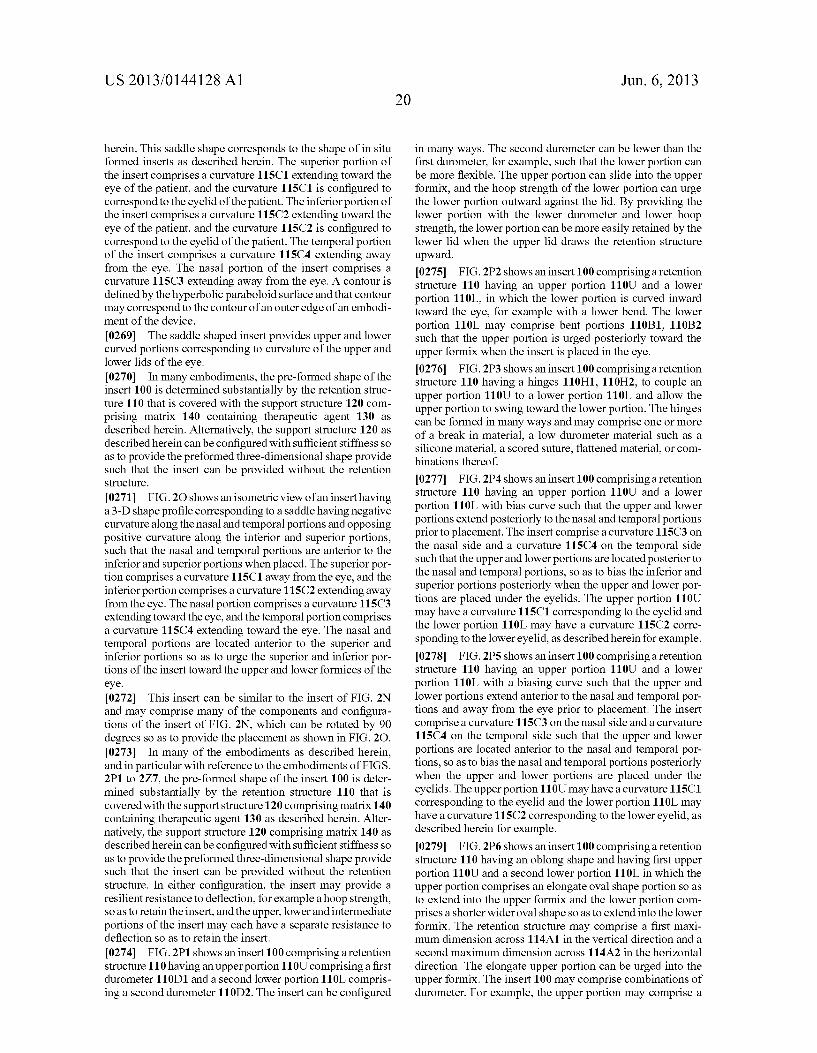
US 2013/0144128A1
herein. This saddle shape corresponds to the shape of in situ formed inserts as described herein. The superior portion of the insert comprises a curvature 115C1 extending toward the eye of the patient, and the curvature 115C1 is configured to correspond to the eyelid of the patient. The inferiorportion of the insert comprises a curvature 115C2 extending toward the eye of the patient, and the curvature 115C2 is configured to correspond to the eyelid of the patient. The temporal portion of the insert comprises a curvature 115C4 extending away from the eye. The nasal portion of the insert comprises a curvature 115C3 extending away from the eye. A contour is defined by the hyperbolic paraboloid surface and that contour may correspond to the contour of an outer edge of an embodi ment of the device. 0269. The saddle shaped insert provides upper and lower curved portions corresponding to curvature of the upper and lower lids of the eye. 0270. In many embodiments, the pre-formed shape of the insert 100 is determined substantially by the retention struc ture 110 that is covered with the support structure 120 com prising matrix 140 containing therapeutic agent 130 as described herein. Alternatively, the support structure 120 as described herein can be configured with sufficient stiffness so as to provide the preformed three-dimensional shape provide such that the insert can be provided without the retention Structure.
0271 FIG.2O shows an isometric view of an insert having a 3-D shape profile corresponding to a saddle having negative curvature along the nasal and temporal portions and opposing positive curvature along the inferior and Superior portions, Such that the nasal and temporal portions are anterior to the inferior and Superiorportions when placed. The Superior por tion comprises a curvature 115C1 away from the eye, and the inferiorportion comprises a curvature 115C2 extending away from the eye. The nasal portion comprises a curvature 115C3 extending toward the eye, and the temporal portion comprises a curvature 115C4 extending toward the eye. The nasal and temporal portions are located anterior to the Superior and inferior portions so as to urge the Superior and inferior por tions of the insert toward the upper and lowerformices of the eye.
0272. This insert can be similar to the insert of FIG. 2N and may comprise many of the components and configura tions of the insert of FIG. 2N, which can be rotated by 90 degrees so as to provide the placement as shown in FIG.2O. 0273. In many of the embodiments as described herein, and in particular with reference to the embodiments of FIGS. 2P1 to 2Z7, the pre-formed shape of the insert 100 is deter mined substantially by the retention structure 110 that is covered with the support structure 120 comprising matrix 140 containing therapeutic agent 130 as described herein. Alter natively, the support structure 120 comprising matrix 140 as described herein can be configured with sufficient stiffness so as to provide the preformed three-dimensional shape provide such that the insert can be provided without the retention structure. In either configuration, the insert may provide a resilient resistance to deflection, for example a hoop strength, So as to retain the insert, and the upper, lower and intermediate portions of the insert may each have a separate resistance to deflection so as to retain the insert. 0274 FIG. 2P1 shows an insert 100 comprising a retention structure 110 having an upperportion 110U comprising a first durometer 110D1 and a second lower portion 110L compris ing a second durometer 110D2. The insert can be configured
20 Jun. 6, 2013
in many ways. The second durometer can be lower than the first durometer, for example, Such that the lower portion can be more flexible. The upper portion can slide into the upper formix, and the hoop strength of the lower portion can urge the lower portion outward against the lid. By providing the lower portion with the lower durometer and lower hoop strength, the lower portion can be more easily retained by the lower lid when the upper lid draws the retention structure upward. 0275 FIG. 2P2 shows an insert 100 comprising a retention structure 110 having an upper portion 110U and a lower portion 110L, in which the lower portion is curved inward toward the eye, for example with a lower bend. The lower portion 110L may comprise bent portions 110B1, 110B2 Such that the upper portion is urged posteriorly toward the upperformix when the insert is placed in the eye. 0276 FIG. 2P3 shows an insert 100 comprising a retention structure 110 having a hinges 110H1, 110H2, to couple an upper portion 110U to a lower portion 110L and allow the upper portion to Swing toward the lower portion. The hinges can be formed in many ways and may comprise one or more of a break in material, a low durometer material Such as a silicone material, a scored Suture, flattened material, or com binations thereof.
0277 FIG. 2P4 shows an insert 100 comprising a retention structure 110 having an upper portion 110U and a lower portion 110L with bias curve such that the upper and lower portions extend posteriorly to the nasal and temporal portions prior to placement. The insert comprise a curvature 115C3 on the nasal side and a curvature 115C4 on the temporal side Such that the upper and lower portions are located posterior to the nasal and temporal portions, so as to bias the inferior and Superior portions posteriorly when the upper and lower por tions are placed under the eyelids. The upper portion 110U may have a curvature 115C1 corresponding to the eyelid and the lower portion 110L may have a curvature 115C2 corre sponding to the lower eyelid, as described herein for example. (0278 FIG. 2P5 shows an insert 100 comprising a retention structure 110 having an upper portion 110U and a lower portion 110L with a biasing curve such that the upper and lower portions extendanterior to the nasal and temporal por tions and away from the eye prior to placement. The insert comprise a curvature 115C3 on the nasal side and a curvature 115C4 on the temporal side such that the upper and lower portions are located anterior to the nasal and temporal por tions, so as to bias the nasal and temporal portions posteriorly when the upper and lower portions are placed under the eyelids. The upper portion 110U may have a curvature 115C1 corresponding to the eyelid and the lower portion 110L may have a curvature 115C2 corresponding to the lower eyelid, as described herein for example. (0279 FIG. 2P6 shows an insert 100 comprising a retention structure 110 having an oblong shape and having first upper portion 110U and a second lower portion 110L in which the upper portion comprises an elongate oval shape portion so as to extend into the upper formix and the lower portion com prises a shorter wideroval shape so as to extend into the lower formix. The retention structure may comprise a first maxi mum dimension across 114A1 in the vertical direction and a second maximum dimension across 114A2 in the horizontal direction. The elongate upper portion can be urged into the upper formix. The insert 100 may comprise combinations of durometer. For example, the upper portion may comprise a
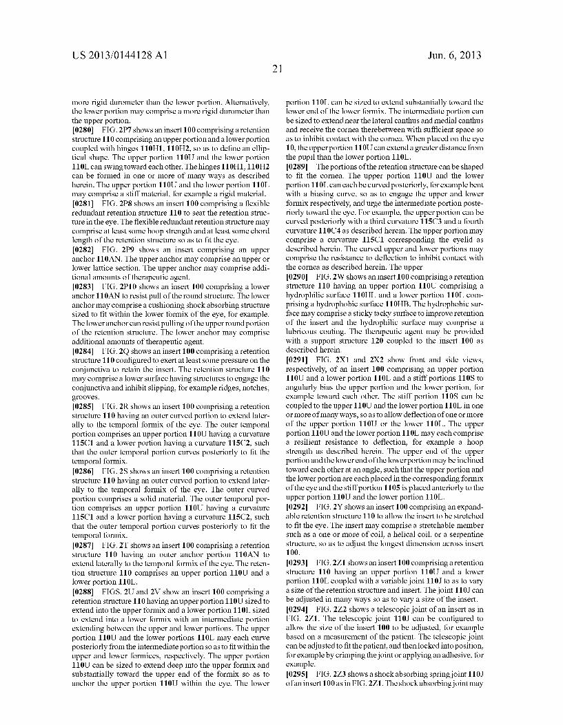
US 2013/0144128A1
more rigid durometer than the lower portion. Alternatively, the lower portion may comprise a more rigid durometer than the upper portion. 0280 FIG.2P7 shows an insert 100 comprising a retention structure 110 comprising an upper portion and a lower portion coupled with hinges 110H1, 110H2, so as to define an ellip tical shape. The upper portion 110U and the lower portion 110L can swing toward each other. The hinges 110H1, 110H2 can be formed in one or more of many ways as described herein. The upper portion 110U and the lower portion 110L may comprise a stiff material, for example a rigid material. (0281 FIG. 2P8 shows an insert 100 comprising a flexible redundant retention structure 110 to seat the retention struc ture in the eye. The flexible redundant retention structure may comprise at least some hoop strength and at least some chord length of the retention structure so as to fit the eye. 0282 FIG. 2P9 shows an insert comprising an upper anchor 110AN. The upper anchor may comprise an upper or lower lattice section. The upper anchor may comprise addi tional amounts of therapeutic agent. (0283 FIG. 2P10 shows an insert 100 comprising a lower anchor 110AN to resist pull of the round structure. The lower anchor may comprise a cushioning shock absorbing structure sized to fit within the lower formix of the eye, for example. The lower anchor can resist pulling of the upper round portion of the retention structure. The lower anchor may comprise additional amounts of therapeutic agent. 0284 FIG.2O shows an insert 100 comprising a retention structure 110 configured to exert at least some pressure on the conjunctiva to retain the insert. The retention structure 110 may comprise a lower Surface having structures to engage the conjunctiva and inhibit slipping, for example ridges, notches, grooves. 0285 FIG. 2R shows an insert 100 comprising a retention structure 110 having an outer curved portion to extend later ally to the temporal formix of the eye. The outer temporal portion comprises an upper portion 110U having a curvature 115C1 and a lower portion having a curvature 115C2, such that the outer temporal portion curves posteriorly to fit the temporal formix. 0286 FIG.2S shows an insert 100 comprising a retention structure 110 having an outer curved portion to extend later ally to the temporal formix of the eye. The outer curved portion comprises a Solid material. The outer temporal por tion comprises an upper portion 110U having a curvature 115C1 and a lower portion having a curvature 115C2, such that the outer temporal portion curves posteriorly to fit the temporal formix. 0287 FIG.2T shows an insert 100 comprising a retention structure 110 having an outer anchor portion 110AN to extend laterally to the temporal formix of the eye. The reten tion structure 110 comprises an upper portion 110U and a lower portion 110L. 0288 FIGS. 2U and 2V show an insert 100 comprising a retention structure 110 having an upper portion 110U sized to extend into the upper formix and a lower portion 110L sized to extend into a lower formix with an intermediate portion extending between the upper and lower portions. The upper portion 110U and the lower portions 110L may each curve posteriorly from the intermediate portion so as to fit within the upper and lower formices, respectively. The upper portion 110U can be sized to extend deep into the upper formix and substantially toward the upper end of the formix so as to anchor the upper portion 110U within the eye. The lower
Jun. 6, 2013
portion 110L can be sized to extend substantially toward the lower end of the lower formix. The intermediate portion can be sized to extend near the lateral canthus and medial canthus and receive the corneatherebetween with sufficient space so as to inhibit contact with the cornea. When placed on the eye 10, the upperportion 110U can extend a greater distance from the pupil than the lower portion 110L. 0289. The portions of the retention structure can be shaped to fit the cornea. The upper portion 110U and the lower portion 110L can each be curved posteriorly, for example bent with a biasing curve, so as to engage the upper and lower formix respectively, and urge the intermediate portion poste riorly toward the eye. For example, the upper portion can be curved posteriorly with a third curvature 115C3 and a fourth curvature 110C4 as described herein. The upper portion may comprise a curvature 115C1 corresponding the eyelid as described herein. The curved upper and lower portions may comprise the resistance to deflection to inhibit contact with the cornea as described herein. The upper 0290 FIG.2W shows an insert 100 comprising a retention structure 110 having an upper portion 110U comprising a hydrophilic surface 110HL and a lower portion 110L com prising a hydrophobic surface 110HB. The hydrophobic sur face may comprise a sticky tacky Surface to improve retention of the insert and the hydrophilic Surface may comprise a lubricous coating. The therapeutic agent may be provided with a support structure 120 coupled to the insert 100 as described herein.
0291 FIG. 2X1 and 2X2 show front and side views, respectively, of an insert 100 comprising an upper portion 110U and a lower portion 110L and a stiff portions 110S to angularly bias the upper portion and the lower portion, for example toward each other. The stiff portion 110S can be coupled to the upper 110U and the lower portion 110L in one or more of many ways, so as to allow deflection of one or more of the upper portion 110U or the lower 110L. The upper portion 110U and the lower portion 110L may each comprise a resilient resistance to deflection, for example a hoop strength as described herein. The upper end of the upper portion and the lower end of the lower portion may be inclined toward each other at an angle, such that the upper portion and the lower portion are each placed in the corresponding formix of the eye and the stiff portion 1105 is placed anteriorly to the upper portion 110U and the lower portion 110L. 0292 FIG.2Y shows an insert 100 comprising an expand able retention structure 110 to allow the insert to be stretched to fit the eye. The insert may comprise a stretchable member Such as a one or more of coil, a helical coil, or a serpentine structure, so as to adjust the longest dimension across insert 1OO.
0293 FIG.271 shows an insert 100 comprising a retention structure 110 having an upper portion 110U and a lower portion 110L coupled with a variable joint 110J to as to vary a size of the retention structure and insert. The joint 110J can be adjusted in many ways so as to vary a size of the insert. 0294 FIG. 2Z2 shows a telescopic joint of an insert as in FIG. 2Z1. The telescopic joint 110J can be configured to allow the size of the insert 100 to be adjusted, for example based on a measurement of the patient. The telescopic joint can be adjusted to fit the patient, and then locked into position, for example by crimping the joint or applying an adhesive, for example. 0295 FIG. 273 shows a shock absorbing spring joint 110J ofan insert 100 as in FIG.271. The shock absorbing joint may
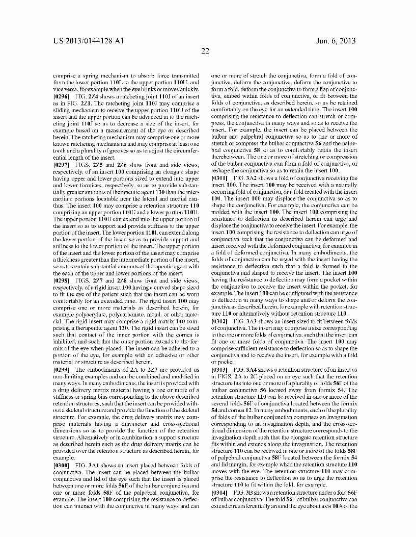
US 2013/0144128A1
comprise a spring mechanism to absorb force transmitted from the lower portion 110L to the upper portion 110U, and Vice versa, for example when the eyeblinks or moves quickly. 0296 FIG. 2Z4 shows a ratcheting joint 110J of an insert as in FIG. 2Z1. The ratcheting joint 110J may comprise a sliding mechanism to receive the upper portion 110U of the insert and the upper portion can be advanced in to the ratch eting joint 110J so as to decrease a size of the insert, for example based on a measurement of the eye as described herein. The ratcheting mechanism may comprise one or more known ratcheting mechanisms and may comprise at least one tooth and a plurality of grooves so as to adjust the circumfer ential length of the insert. 0297 FIGS. 275 and 2Z6 show front and side views, respectively, of an insert 100 comprising an elongate shape having upper and lower portions sized to extend into upper and lower formices, respectively, so as to provide Substan tially greater amounts of therapeutic agent 130 than the inter mediate portions locatable near the lateral and medial can thus. The insert 100 may comprise a retention structure 110 comprising an upper portion 110U and a lower portion 110U. The upper portion 110U can extend into the upper portion of the insert So as to Support and provide stiffness to the upper portion of the insert. The lower portion 110L can extendalong the lower portion of the insert So as to provide Support and stiffness to the lower portion of the insert. The upper portion of the insert and the lower portion of the insert may comprise a thickness greater than the intermediate portion of the insert, so as to contain substantial amounts of therapeutic agent with the each of the upper and lower portions of the insert. 0298 FIGS. 2Z7 and 2Z8 show front and side views, respectively, of a rigid insert 100 having a curved shape sized to fit the eye of the patient such that the insert can be worn comfortably for an extended time. The rigid insert 100 may comprise one or more materials as described herein, for example polyacrylate, polycarbonate, metal, or other mate rial. The rigid insert may comprise a rigid matrix 140 com prising a therapeutic agent 130. The rigid insert can be sized Such that contact of the inner portion with the cornea is inhibited, and such that the outer portion extends to the for mix of the eye when placed. The insert can be adhered to a portion of the eye, for example with an adhesive or other material or structure as described herein.
0299. The embodiments of 2A to 2Z7 are provided as non-limiting examples and can be combined and modified in many ways. In many embodiments, the insertis provided with a drug delivery matrix material having a one or more of a stiffness or spring bias corresponding to the above described retention structures, such that the insert can be provided with out a skeletal structure and provide the function of the skeletal structure. For example, the drug delivery matrix may com prise materials having a durometer and cross-sectional dimensions so as to provide the function of the retention structure. Alternatively or in combination, a Support structure as described herein such as the drug delivery matrix can be provided over the retention structure as described herein, for example. 0300 FIG. 3A1 shows an insert placed between folds of conjunctiva. The insert can be placed between the bulbar conjunctiva and lid of the eye such that the insert is placed between one or more folds 56F of the bulbar conjunctiva and one or more folds 58F of the palpebral conjunctiva, for example. The insert 100 comprising the resistance to deflec tion can interact with the conjunctiva in many ways and can
22 Jun. 6, 2013
one or more of stretch the conjunctiva, form a fold of con junctiva, deform the conjunctiva, deform the conjunctiva to form a fold, deform the conjunctiva to form a flap of conjunc tiva, embed within folds of conjunctiva, or fit between the folds of conjunctiva, as described herein, so as be retained comfortably on the eye for an extended time. The insert 100 comprising the resistance to deflection can stretch or com press, the conjunctiva in many ways and so as to receive the insert. For example, the insert can be placed between the bulbar and palpebral conjunctiva so as to one or more of stretch or compress the bulbar conjunctiva 56 and the palpe bral conjunctiva 58 so as to comfortably retain the insert therebetween. The one or more of stretching or compression of the bulbar conjunctiva can form a fold of conjunctiva, or reshape the conjunctiva so as to retain the insert 100. 0301 FIG. 3A2 shows a fold of conjunctiva receiving the insert 100. The insert 100 may be received with a naturally occurring fold of conjunctiva, or a fold created with the insert 100. The insert 100 may displace the conjunctiva so as to shape the conjunctiva. For example, the conjunctiva can be molded with the insert 100. The insert 100 comprising the resistance to deflection as described herein can urge and displace the conjunctiva to receive the insert. For example, the insert 100 comprising the resistance to deflection can urge of conjunctiva Such that the conjunctiva can be deformed and insert received with the deformed conjunctiva, for example in a fold of deformed conjunctiva. In many embodiments, the folds of conjunctiva can be urged with the insert having the resistance to deflection such that a fold is formed in the conjunctiva and shaped to receive the insert. The insert 100 having the resistance to deflection may form a pocket within the conjunctiva to receive the insert within the pocket, for example. The insert 100 can be configured with the resistance to deflection in many ways to shape and/or deform the con junctiva as described herein, for example with retention struc ture 110 or alternatively without retention structure 110. 0302 FIG. 3A3 shows an insert sized to fit between folds of conjunctiva. The insert may comprise a size corresponding to the one or more folds of conjunctiva, Such that the insert can fit one or more folds of conjunctiva. The insert 100 may comprise Sufficient resistance to deflection so as to shape the conjunctiva and to receive the insert, for example with a fold or pocket. 0303 FIG. 3A4 shows a retention structure of an insert as in FIGS. 2A to 2C placed on an eye such that the retention structure fits into one or more of a plurality offolds 56F of the bulbar conjunctiva 56 located away from formix 54. The retention structure 110 can be received in one or more of the several folds 56F of conjunctiva located between the formix 54 and cornea 12. In many embodiments, each of the plurality of folds of the bulbar conjunctiva comprises an invagination corresponding to an invagination depth, and the cross-sec tional dimension of the retention structure corresponds to the invagination depth Such that the elongate retention structure fits within and extends along the invagination. The retention structure 110 can be received in one or more of the folds 58F of palpebral conjunctiva 58F located between the formix 54 and lid margin, for example when the retention structure 110 moves with the eye. The retention structure 110 may com prise the resistance to deflection so as to urge the retention structure 110 to fit within the fold, for example. 0304 FIG.3B shows a retention structure under a fold 56F of bulbar conjunctiva. The fold 56F of bulbar conjunctiva can extend circumferentially around the eye about axis 10A of the
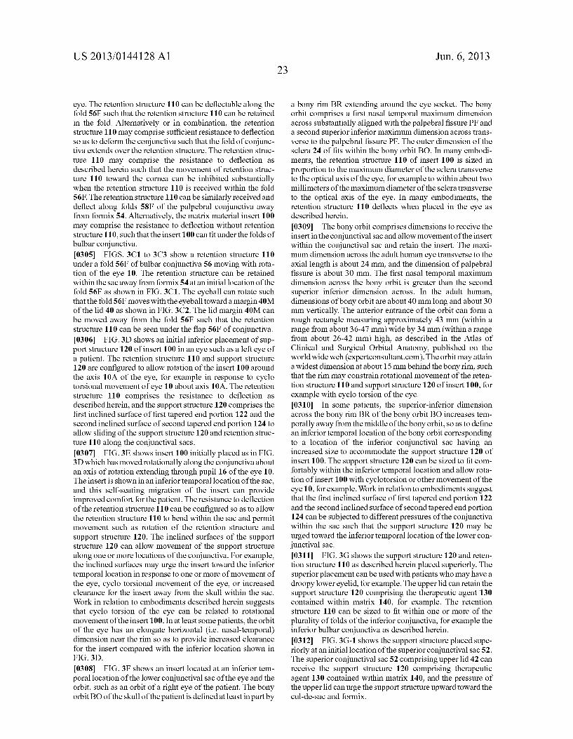
US 2013/0144128A1
eye. The retention structure 110 can be deflectable along the fold 56F such that the retention structure 110 can be retained in the fold. Alternatively or in combination, the retention structure 110 may comprise sufficient resistance to deflection So as to deform the conjunctiva Such that the fold of conjunc tiva extends over the retention structure. The retention struc ture 110 may comprise the resistance to deflection as described herein such that the movement of retention struc ture 110 toward the cornea can be inhibited substantially when the retention structure 110 is received within the fold 56F. The retention structure 110 can be similarly received and deflect along folds 58F of the palpebral conjunctiva away from formix 54. Alternatively, the matrix material insert 100 may comprise the resistance to deflection without retention structure 110, such that the insert 100 can fit under the folds of bulbar conjunctiva. 0305 FIGS. 3C1 to 3C3 show a retention structure 110 under a fold 56F of bulbar conjunctiva 56 moving with rota tion of the eye 10. The retention structure can be retained within the sac away from formix54 at an initial location of the fold 56F as shown in FIG. 3C1. The eyeball can rotate such that the fold56F moves with the eyeball toward a margin 40M of the lid 40 as shown in FIG. 3C2. The lid margin 40M can be moved away from the fold 56F such that the retention structure 110 can be seen under the flap 56F of conjunctiva. 0306 FIG. 3D shows an initial inferior placement of Sup port structure 120 of insert 100 in an eye such as a left eye of a patient. The retention structure 110 and support structure 120 are configured to allow rotation of the insert 100 around the axis 10A of the eye, for example in response to cyclo torsional movement of eye 10 about axis 10A. The retention structure 110 comprises the resistance to deflection as described herein, and the support structure 120 comprises the first inclined surface of first tapered end portion 122 and the second inclined Surface of second tapered end portion 124 to allow sliding of the support structure 120 and retention struc ture 110 along the conjunctival sacs. 0307 FIG.3E shows insert 100 initially placed as in FIG. 3D which has moved rotationally along the conjunctiva about an axis of rotation extending through pupil 16 of the eye 10. The insert is shown in an inferior temporal location of the sac, and this self-seating migration of the insert can provide improved comfort for the patient. The resistance to deflection of the retention structure 110 can be configured so as to allow the retention structure 110 to bend within the sac and permit movement such as rotation of the retention structure and support structure 120. The inclined surfaces of the support structure 120 can allow movement of the support structure along one or more locations of the conjunctiva. For example, the inclined surfaces may urge the insert toward the inferior temporal location in response to one or more of movement of the eye, cyclo torsional movement of the eye, or increased clearance for the insert away from the skull within the sac. Work in relation to embodiments described herein suggests that cyclo torsion of the eye can be related to rotational movement of the insert 100. In at least some patients, the orbit of the eye has an elongate horizontal (i.e. nasal-temporal) dimension near the rim so as to provide increased clearance for the insert compared with the inferior location shown in FIG. 3D.
0308 FIG. 3F shows an insert located at an inferior tem poral location of the lower conjunctival sac of the eye and the orbit, such as an orbit of a right eye of the patient. The bony orbit BO of the skull of the patient is defined at least in part by
Jun. 6, 2013
a bony rim BR extending around the eye socket. The bony orbit comprises a first nasal temporal maximum dimension across substantially aligned with the palpebral fissure PF and a second Superior inferior maximum dimension across trans verse to the palpebral fissure PF. The outer dimension of the sclera 24 of fits within the bony orbit BO. In many embodi ments, the retention structure 110 of insert 100 is sized in proportion to the maximum diameter of the Sclera transverse to the optical axis of the eye, for example to within about two millimeters of the maximum diameter of the sclera transverse to the optical axis of the eye. In many embodiments, the retention structure 110 deflects when placed in the eye as described herein.
0309 The bony orbit comprises dimensions to receive the insert in the conjunctival sac and allow movement of the insert within the conjunctival sac and retain the insert. The maxi mum dimension across the adult human eye transverse to the axial length is about 24 mm, and the dimension of palpebral fissure is about 30 mm. The first nasal temporal maximum dimension across the bony orbit is greater than the second Superior inferior dimension across. In the adult human, dimensions of bony orbit are about 40 mm long and about 30 mm vertically. The anterior entrance of the orbit can form a rough rectangle measuring approximately 43 mm (within a range from about 36-47 mm) wide by 34 mm (within a range from about 26-42 mm) high, as described in the Atlas of Clinical and Surgical Orbital Anatomy, published on the worldwide web (expertconsultant.com). The orbit may attain a widest dimension at about 15 mm behind the bony rim, such that the rim may constrain rotational movement of the reten tion structure 110 and support structure 120 of insert 100, for example with cyclo torsion of the eye. 0310. In some patients, the superior-inferior dimension across the bony rim BR of the bony orbit BO increases tem porally away from the middle of the bony orbit, so as to define an inferior temporal location of the bony orbit corresponding to a location of the inferior conjunctival sac having an increased size to accommodate the Support structure 120 of insert 100. The support structure 120 can be sized to fit com fortably within the inferior temporal location and allow rota tion of insert 100 with cyclotorsion or other movement of the eye 10, for example. Work in relation to embodiments suggest that the first inclined surface of first tapered end portion 122 and the second inclined surface of second tapered end portion 124 can be subjected to different pressures of the conjunctiva within the sac such that the support structure 120 may be urged toward the inferior temporal location of the lower con junctival sac. 0311 FIG. 3G shows the support structure 120 and reten tion structure 110 as described herein placed superiorly. The Superior placement can be used with patients who may have a droopy lower eyelid, for example. The upper lid can retain the support structure 120 comprising the therapeutic agent 130 contained within matrix 140, for example. The retention structure 110 can be sized to fit within one or more of the plurality of folds of the inferior conjunctiva, for example the inferior bulbar conjunctiva as described herein. 0312 FIG. 3G-1 shows the support structure placed supe riorly at an initial location of the Superior conjunctival sac 52. The Superior conjunctival sac 52 comprising upper lid 42 can receive the Support structure 120 comprising therapeutic agent 130 contained within matrix 140, and the pressure of the upper lid can urge the Support structure upward toward the cul-de-sac and formix.

US 2013/0144128A1
0313 FIG.3G-2 shows the support structure 120 seated in the cul-de-sac 53 comprising formix 54 of the superior con junctival sac 52 following placement as in FIG. 3G-1. The retention structure 110 can extend along the lower sac and fit within the one or more folds of the lower sac, for example bulbar folds, as described herein. 0314 FIG. 3H shows the support structure 120 located at an inferior nasal location of the eye so as to extend near the caruncle. The Support structure 120 may comprise a low resistance to deflection, for example less than the retention structure 110, such that the support structure and retention structure can deflect together on the eye. This low resistance to deflection can permit placement of the Support structure 120 at many locations as described herein. 0315 FIG. 3I shows the support structure 120 placed at a temporal location of the eye. 0316 FIG. 3J shows retention structure 110 comprising a
first portion 162 having a first resistance to deflection and a second portion 164 having a second resistance to deflection less than the first portion. The first resistance to deflectionless than the second resistance to deflection may comprise one or more of a varying thickness of retention structure 110, a varying material of retention structure 110 or a plurality of materials of retention structure 110. The first portion 162 may comprise a greater cross sectional dimension; e.g., diameter, than the second portion, so as to increase the resistance to deflection of the first portion relative to the second portion, for example. This increased resistance to deflection can permit the first portion 162 of the retention structure to be placed under the superior (upper) lid so as to inhibit movement of the first portion 162 toward the cornea. The sizing of the first portion 162 can urge the first portion toward the formix 54. The relatively smaller cross-sectional size of the second por tion 164 can permit the second portion to fit within the one or more folds of the inferior (lower) sac of the eye as described herein.
0317 FIG. 3J-1 shows a side cross sectional view of the retention structure 110 as in FIG. 3.J. The retention structure 110 may comprise a cross sectional dimension 112 of the elongate second portion of the retention structure, and a cross sectional dimension 113 of the first portion 162 of the reten tion structure. The first portion 162 and the second portion 164 may comprise Substantially the same material Such that the thinner second portion has the resistance to deflection lower than the thicker second portion as described herein. 0318 FIG. 3K shows an insert 100 comprising a support structure 120 comprising a matrix 140 of therapeutic agent 130 on the retention structure 110 as in FIG. 3.J. The support structure 120 can be located on retention structure 110 so as to correspond to one or more Support structure locations as described herein, such as nasal placement, temporal place ment, inferior placement, Superior placement, or inferior tem poral placement, when the wider first portion 162 is placed Superiorly, for example. For example, the Support structure 120 comprising the matrix 140 and the wider first portion 162 can be placed Superiorly, for example. Alternatively or in combination, the Support structure 120 comprising matrix 140 of therapeutic agent 130 can be placed at one or more of many locations on the retention structure 110 corresponding to one or more locations of the eye when the first portion is placed superiorly. For example, the support structure 120 comprising matrix 140 containing therapeutic agent 130 can
24 Jun. 6, 2013
be located on retention structure 110 for placement inferiorly when the wider first portion 162 is placed superiorly, for example. 0319 FIG. 3L shows an insert comprising a lubricous coating. The lubricous 170 coating can allow the insert to move along the conjunctiva of the eye and can cover one or more of the retention structure 110 or the support structure 120. For example, the lubricous coating may cover the Sup port structure 120 comprising matrix 140 containing thera peutic agent 130, and the therapeutic agent 130 can be released through the surface of the matrix 140 as described herein. Alternatively or in combination, the lubricous coating may cover at least a portion of the retention structure. For example the lubricous coating 170 may cover a portion of the retention structure corresponding to locations near the lacri mal gland. Alternatively, the lubricous coating 170 may cover the Support structure and the retention structure, for example with dip coating of insert 100. 0320 FIG.3L-1 shows a layer 172 of the lubricous coating 170 on a surface 172 of the matrix 140 as in FIG.3L. The layer 172 may extend over the surface the matrix 140 that releases the therapeutic agent as described herein. The therapeutic agent 130 can be released through the layer 172, and the rate of release can be determined substantially by surface area of the matrix 140 and the solubility of the therapeutic agent in the tear of the eye. 0321. The lubricous coating may comprise one or more of an oil, a Surfactant, a hydrogel, polyvinyl alcohol (PVA). hydroxyethyl methacrylate (HEMA), sodium polyacrylate, acrylate polymers and copolymers having hydrophilic groups, N-vinylpyrrolidone (NVP), agarose, methylcellu lose, ethylene oxide (ETO), polyethylene oxide (PTO) or hyaluronan, for example. 0322 FIG. 4A shows an insert comprising a plurality of therapeutic agents loaded on a first portion of the Support structure 120 and a second portion of the support structure 120. The support structure 120 can be configured to reside in the inferior temporal location of the conjunctival sac or other location as described herein. The plurality of therapeutic agents may comprise therapeutic agent 130 contained within matrix 140 and a second therapeutic agent 132 contained within a second matrix 142, for example. The first matrix 140 and second matrix 142 may comprise similar materials, for example silicone elastomer comprising siloxane. While many matrix materials can be used, work in relation to embodi ments Suggests that known commercially available silicone elastomer from NuSil can be used as the matrix material. 0323 FIG. 4B shows a matrix comprising inclusions 131 of a therapeutic agent 130 in matrix 140. The inclusions 131 may comprise particles of the therapeutic agent such as one or more of solid particles, liquid particles, crystals or droplets of the therapeutic agent within the matrix 140. The solid par ticles can provide release of therapeutic amounts of the thera peutic agent for an extended time, and the release rate con nects can be one of more of Zero order release, first order release, or intermediate release rates, or combinations thereof. For example, the release rate can be substantially Zero order when the inclusions 131 remain in the matrix and transition to substantially first order when the inclusions have substantially dissolved. 0324 FIG. 4C shows support structure 120 comprising a plurality of Support structures, in which the plurality of Sup port structures comprise a plurality of therapeutic agents placed together on a retention structure at a location corre
US 2013/0144128A1
sponding to placement along an inferior temporal portion of the conjunctiva of the eye. The plurality of support structures can be spaced apart so as to extenda distance 126 on retention structure 120 suitable for placement along the inferior tem poral portion of the conjunctival sac as described herein. The plurality of structures may comprise therapeutic agent 130 within matrix 140 to release the therapeutic agent and second therapeutic agent 132 within second matrix 142 to release the second therapeutic agent. 0325 FIG. 4D shows a support structure 120 comprising a plurality of Support structures located along retention struc ture 110 to release the therapeutic agent 130. The plurality of Support structures can be shaped in many ways, and may comprise round objects such as spherical balls, or cylinders, for example. The plurality of Support structures can extend a distance along retention structure 110 for placement in the inferior temporal location of the conjunctival sac. The plural ity of objects may increase the Surface area of the matrix to increase the rate of release of the therapeutic agent with the increased Surface area, for example. 0326 FIG. 4E shows release of a therapeutic agent from a matrix 140 having a surface area sized to treat the patient for an extended time. The matrix 140 comprises a Surface area defined substantially by distance 126 and cross sectional dimension 127. Such as a diameter. The cross-sectional dimension may correspond to a distance around the structure 120 such as a circumference 127C. The area of the matrix 140 may correspond substantially to the circumference 127C multiplied by the distance 126. 0327 FIG. 4F shows release of a therapeutic agent from a spherical Surface of a Support structure 120 comprising matrix located on a retention structure 110. The spherical Surface has an area to release therapeutic amounts of the therapeutic agent for the extended time. The structure 120 comprises dimension across 127, which may comprise a diameter across the spherical structure. The Surface area of the matrix can be readily determined in many ways by one of ordinary skill in the art, for example by the relationship: Surface Area=PI*(Diameter)2. 0328 FIG. 4G shows support structure 120 comprising a plurality of at least three Support structures along a retention structure comprising a plurality of at least three therapeutic agents. The structure comprising the at least three therapeutic agents can extend a distance 126 for placement in the con junctival sac, for example within an inferior temporal portion of the sac as described herein. The at least three support structures may comprise a first Support structure 120A com prising a first therapeutic agent 130, a second Support struc ture 120B comprising a second therapeutic agent 132 and a third Support structure comprising a third therapeutic agent 134. The first therapeutic agent 130 can be contained within first matrix 140, the second therapeutic agent 132 contained within second matrix 142 and the third therapeutic agent 134 contained within third matrix 144. Each of the therapeutic agents may be contained on one or more matrices of one or more Support structures. 0329 FIG. 4G-1 shows a plurality of support structures comprising a first therapeutic agent contained within a first matrix and a second therapeutic agent contained within a second matrix. The insert 100 may comprise a Support struc ture 120 comprising a plurality of segments in which each segment comprises a matrix to contain a therapeutic agent. The first segment 120ASA may comprise the first therapeutic agent 130 contained in the first matrix 140 as described
Jun. 6, 2013
herein. The second segment 120BSA may comprise the sec ond therapeutic agent 132 contained in a second matrix 142. The first segment can be separated from the second segment with a separator 120S. The first segment, the second segment, and the separator may comprise similar materials, for example silicone elastomer, Such that the first segment and the second segment can bond to the separator. Each of the segments may comprise segments of a ring and be sized to slide along the conjunctival sacs with torsion as described herein. The retention structure 110 may extend through each of the segments and the separator. 0330. The surface area and loading of the therapeutic agent of each segment may correspond to the rate of release of each therapeutic agent. For example, different regions of the insert, for example different segments may have different drugs and surface areas of the matrix for different release rates. The first therapeutic agent may comprise a prostaglan din Such as one or more of bimatoprost, latanoprost, or tra voprost, and the second therapeutic agent may comprise a beta blocker such as timolol. The beta blocker can be released at a rate that is faster than the prostaglandin, for example within a range from about 5 to 20 times the rate of release of the prostaglandin, for example 10x. The portion of Support structure 120 comprising the beta blocker may comprise a proportionally greater Surface area to provide the rate of release, for example a Surface area that is at least about twice the Surface area of the prostaglandin, for example a Surface area within a range from about 5 to 20 times the surface area of the prostaglandin. The prostaglandin and the beta blocker may each comprise inclusions within the first or second matrix, respectively. 0331 Each segment comprising the Surface area and therapeutic agent may be coated. The coating may comprise a material that readily passes the therapeutic agent, such as a hydrogel. Alternatively, the coating may comprise a material that inhibits release of the therapeutic agent, and a size and number of the holes for each segment configured to release the therapeutic agent at therapeutic rates for an extended time. For example, the size and number of holes of the segment comprising the beta blocker can provide at least about 2 twice the surface area to release the beta blocker, for example at least about 5 to 20 times the surface area to release the beta blocker relative to the prostaglandin. In many embodiments, one or more of the support structure 120 and the retention structure 110 comprise a pre-insertion three dimensional shape profile as described herein, for example to resist deflec tion away from the inferior bulbar conjunctiva. 0332 FIG. 4G-2 shows a retention structure comprising a ring, in which the ring comprises a plurality of ring segments. The retention structure 110 may comprise the support struc ture 120 to contain the therapeutic agent 130. The ring seg ments may comprise different drugs at different rates on single ring. The insert 100 comprising the ring structure may comprise a substantially constant cross-sectional diameter, or a varying cross-sectional diameter as described herein. The insert 100 comprises a first support portion 120A comprising a first therapeutic agent 130, a second support portion 120B comprising a second therapeutic agent 132 and a third portion Substantially without therapeutic agent and comprising a retention structure 110. The first portion 120A can be sepa rated from the third portion with a first separator 120S1. The first portion 120A can be separated from the second portion 120B with a second separator 120S2. The second portion can be separated from the third portion with a third separator
US 2013/0144128A1
120S3. Each of the first portion 120A, the second portion 120B, the third portion, the first separator, the second sepa rator and the third separator may comprise a similar material, for example silicone. The portions can contact the separators So as to bond to the separators when the portions are cured, Such that the insert may comprise a plurality of segment portions bonded together with the separators. 0333 FIG. 4G-3 shows an annular insert comprising a retention structure comprising 100 an annular ring and an annular support 120 comprising a matrix 140 of therapeutic agent 130 covering the retention structure. The annular Sup port structure 120 comprises a cross-sectional dimension 127 sized to provide therapeutic amounts of the therapeutic agent for the extended time. The matrix may comprise one or more of many materials as described herein, for example silicon and therapeutic agent.
0334 FIG.4G-4 shows across-sectional view of the reten tion structure and support structure of FIG. 4G-3. The cross sectional dimension 117D across the retention structure 110 is sized to provide the resistance to deflection so as to retain the insert within the eye, for example with the hoop strength. The retention structure 110 may comprise one or more of many materials as described herein, Such as a silicone having a durometer of at least about 60A, for example a durometer of 80A. In many embodiments, the retention structure 110 com prises a durometer less than the durometer of matrix 140. 0335 An insert comprising unitary structure can be uti lized with the drug eluting structure and resistance to deflec tion, as described herein. The unitary insert can be configured So as to provide deflection, and drug release as described herein. The insert may comprise inclusions of a therapeutic agent contained in a matrix as described herein. The matrix containing the therapeutic agent may comprise strength and resistance to deflection similar to the insert comprising the skeleton as described herein. The matrix 140 may comprise a Support 120 comprising a Support material of the matrix. The matrix 140 may comprise a Support material having a hard ness So as to provide the resistance to deflection as described herein, such that the function of the retention structure can be provided by the matrix 140 without the retention structure, for example. The Support material may comprise one or more of a silicone, a polyacrylate, or a polycarbonate for example, having a harness Sufficient to provide the resistance to deflec tion.
0336. The cross-sectional dimension across a portion of the insert can be sized to provide the resistance to deflection so as to retain the insert within the eye, for example with the resistance to self-loading deflection as described herein. The material may comprise a durometer of 50 A or more, for example 80 A or more, so as to provide the resistance to deflection. In many embodiments, the unitary insert com prises a silicone material having a durometer of about 80 A or more, and inclusions of the therapeutic agent. 0337 The unitary insert comprising one or more of the resistance to deflection, the resistance to self-loading deflec tion, the self-loading deflection angle, the torsional resistance twisting, or the hoop strength, or combinations thereof as described herein, can be combined with any one or more shapes or structures as described herein. For example, the unitary insert may comprise the one or more of self-loading resistance to deflection, the self-loading deflection angle, the hinges, the 3D shape profile, the bias, the curved bias, or the
26 Jun. 6, 2013
dual durometer upper and lower portions, for example, with reference to Tables 1A to 1D and FIGS. 2A to 2Z7, for example. 0338 FIG. 4H shows an insert 100 comprising a support structure 120 comprising an at least partially erodible struc ture 170 comprising an erodible material 176 to release a therapeutic agent 130 for an extended time. The erodible structure 170 can be coupled to the retention structure 110 as described herein.
0339 FIG. 4I shows a transverse cross sectional view of the at least partially erodible structure 170 comprising the erodible material 176 as in FIG. 4H. A barrier material 174 is shaped to define a chamber 172 of the support structure 120. A channel 173 extends from chamber 172 to an opening to release the therapeutic agent. The channel 176 can be blocked with an erodible material to inhibit release of the therapeutic agent 130 contained in the chamber. When material 176 erodes, the channel 173 opens to release the therapeutic agent. 0340 FIG. 4J shows a side cross sectional view of the structure 170 comprising the erodible material 176 as in FIGS. 4H and 4I. A plurality of chambers may contain thera peutic agent 130, and the plurality of chambers may comprise a first chamber 172 and a second chamber 174. The erodible material may be located on a Substantially non-erodible Sup port, such as a substrate 178, and the erodible material occupy a channel defined with a substantially non-erodible material, Such that the material erodes along an exposed surface of the material. The substrate 178 can be positioned on a first side of the erodible material and the plurality of chambers on a sec ond side of the erodible material so as to define an erosion path 179. The erosion path may comprise a linear path, and the containers may comprise openings arranged along the linear path to release the therapeutic agent from each con tainer in sequence. The erosion path can be linear, for example straight, or curved. The erosion path can be arranged to sequentially release the therapeutic agent from each of the plurality of chambers, for example from the first chamber first and the second chamber second. Alternatively, the order can be reversed. The rate of erosion and spacing of the chambers can be arranged so as to release an amount of the therapeutic agent at Substantially regular intervals, for example daily. The plurality of chambers and erodible material can be arranged in many ways to release the therapeutic agent at regular inter vals for an extended time of at least one week, for example one month or more such as an extended time of two or more months. For example, the plurality of chambers may com prise 90 chambers to release a therapeutic amount each day for at least about three months. The plurality of chambers may comprise 180 or more chambers to provide the extended release for at least about 6 months, for example. The sizing of the chambers and spacing can be manufactured in many ways, for example with nano-technology and etching to form the chambers and deposition to form the erodible material. 0341 FIG. 4K shows a reservoir chamber having channel 173 occluded with erodible material 176 as in FIGS. 4H to 4.J.
0342 FIG. 4L shows the container as in FIG. 4K having the material 176 eroded away from the channel to release the therapeutic agent 130 from the reservoir chamber. 0343 FIG. 4M shows a pump 180 to release a therapeutic agent 130 with pulsatile flow. The pump 180 may comprise one or more of many pumps such as an osmotic pump 182, and active pump such as a micro-electro-mechanical (herein after “MEMS) pump. The pump can be configured to pro