Embed Size (px)
Citation preview

US Deportment of Transportation
1200 New Jersey Ave SE Washing ton DC 20590
Federal HighwayAdministration May 6 20 16
In Reply Refer To
HSSTWZ-340 Mr Felipe Almanza
TrafFix Devices Inc
160 A venida La Pata
San Clemente CA 92672
Dear Mr Almanza
This letter is in response to your February 26 20 15 reques t for the Federa l Highway
Administration (Fl lVA) to review a roadside sarety device hardware or system for el igibili ty
for reimbursement under the Federal-aid highway program This r11 wA letter ofeligibility is
assigned FHWA control number VZ-3-W and is valid until a subsequent letter is issued by
Fl IWA that expressly rcforcnccs thi s device
Decision
The fo llowing devices are e ligible with detail s provided in the fo rm which is attached as an
integra l part of this letter
bull ADA Urbanite Longitudina l Channelizing Device
Scope of this Letter
To be found eligible for Federal-a id fund ing new roadside safety devices should meet the crash
test and evaluation criteria contained in the American Association of State I lighway and
Transportation Officia lsmiddot Manual for Assessing Sa rcty Hardware (MASH) However the
FHWA the Department of Transportation and the United States Government do not regulate the
manufac ture of roadside safety devices Eligibi lity fo r reimbursement under the Federal-aid
highway program does not establish approval certification or endorsement of the device for any
parti cular purpose or use
This letter is not a determination by the FHWA the Department of Transportation or the United
States Government that a vehicle crash involving the device wi ll result in any particular outcome
no r is it a guarantee of the in-service performance of this device Proper manufac turing
insta ll at ion and main tenance are requ ired in order fo r this device to function as tested
This find ing of eligibil ity is li mited to the crashworthiness of the system and docs not cover other
structural features nor conformity middotith the Manual on Uniform Traflic Control Devices
2
Eligibility for Reimbursement
Based solely on a review ofcrash test results and certifications submitted by the manufacturer
and the crash test laboratory FHWA agrees that the device described herein meets the crash test
and evaluation criteria of the American Association of State Highway and Transportation
Officials Manual for Assessing Safety Hardware (MASH) Therefore the device is eligible for
reimbursement under the Federal-aid highway program if installed under the range of tested conditions
Name of system ADA Urbanite Longitudinal Channelizing Device
Type of system Work Zone
Test Level MASH Test Level 3 (TL3)
Testing conducted by KARCO
Task Force 13 Designator na
Date of request February 26 2015
Date initially acknowledged March 26 2015
Date ofcompleted package March 26 2015
FHWA concurs with the recommendation of the accredited crash testing laboratory as stated
within the attached form
Full Description of the Eligible Device
The device and supporting documentation including reports of the crash tests or other testing
done videos of any crash testing andor drawings of the device are described in the attached
form
Notice
Ifa manufacturer makes any modification to any of their roadside safety hardware that has an
existing eligibility letter from FHW A the manufacturer must notify FHW A of such modification
with a request for continued eligibility for reimbursement The notice of all modifications to a
device must be accompanied by
o Significant modifications - For these modifications crash test results must be
submitted with accompanying documentation and videos
o Non-signification modifications - For these modifications a statement from the
crash test laboratory on the potential effect of the modification on the ability of
the device to meet the relevant crash test criteria
FHW As determination of continued eligibility for the modified hardware will be based on
whether the modified hardware will continue to meet the relevant crash test criteria
3
You are expected to supply potential users with sufficient information on design installation and maintenance requirements to ensure proper performance
You are expected to certify to potential users that the hardware furnished has the same chemistry
mechanical properties and geometry as that submitted for review and that it will meet the test and evaluation criteria of the MASH
Issuance of this letter does not convey property rights of any sort or any exclusive privilege
This letter is based on the premise that information and reports submitted by you are accurate and correct We reserve the right to modify or revoke this letter if ( I) there arc any inaccuracies
in the information submitted in support of your requesc for this letter (2) the qualification resting
was flawed (3) in-service performance or other information reveals safety problems (4) the
system is significantly different from the version that was crash tested or (5) any other
information indicates that the letter was issued in error or otherwise does not reflect full and
complete in formation about the crash worthiness of the system
Standard Provisions
bull To prevent misunderstanding by others this letter of eligibility designated as FHWA
control number WZ-340 shall not be reproduced except in full This letter and the test
documentation upon which it is based are public information All such tellers and
documentation may be reviewed upon request
bull This letter shall not be construed as authorization or consent by the FH WA to use
manufacture or sell any patented system for which the applicant is not the patent holder
bull If the subject device is a patented product it may be considered to be proprietary If
propriecary systems are specified by a highway agency for use on Federal-aid projects
(a) they must be supplied through competitive bidding with equally suitable unpatentcd
items (b) the highway agency must certify that they arc essential for synchronization
with the existing highway facilities or that no equally suitable alternative exists or (c)
they must be used for research or for a distinctive type of construction on relatively short
sections of road for experimental purposes Our regulations concerning proprietary
products are contained in Title 23 Code of Federal Regulations Section 635411
Sinccrelx yours
LQエゥOセ $ セヲウォャMichael S Griffith
Director Office of Safety Technologies
Office of Safety
Enclosures
Version 91 1115)
Page 1 of 3
Request for Federal Aid Reimbursement Eligibility ofHighway Safety Hardware
Date of Request February 26 2015 I (e New ( Resubmission
Name Felipe Almanza QI
tmiddote Company Traffix Devices Inc
Address 160 Avenida la Pata San Clemente CA 92672 セJ
111 Country United States
To Michael S Griffith Director
FHWA Office of Safety Technologies
I request the following devices be considered eligible for reimbursement under the Federal-aid highway program
I1-1-q
System Type Submission Type Device Name I Variant Testing Criterion Test
level
WZ Crash Worthy Work
Zone Traffic Control Devices
(i Physical Crash Testing
(Engineering Analysis
ADNUrbanite
Longitudinal
Channelizing Device
AASHTOMASH Tl3
By submitting this request for review and evaluation by the Federal Highway Administration I certify
that the product(s) was (were) tested in conformity with the AASHTO Manual for Assessing Safety
Hardware and that the evaluation results meet the appropriate evaluation criteria in the MASH
Identification of the individual or organization responsible for the product
Contact Name Felipe Almanza Same as Submitter 181
Company Name Traffix Devices Inc Same as Submitter 181
Address 160 Avenida La Pata San Clemente CA 92672 Same as Submitter 181
Country United States Same as Submitter 181 Enter below all disclosures of financial interests as required by the FHWA Federal-Aid Reimbursement
Eligibility Process for Safety Hardware Devices document
TrafFix Devices Inc Corporate Office 160 Avenida la Pata San Clemente CA 92672 and Karco Engineering LlC
9270 Holly Road Adelanto CA 92301 share no ($000) financial interests between the two organizations
This includes no ($000) shared financial interest but not limited to
i Compensation including wages salaries commissions professional fees or fees for business referrals (dollar
values are not needed)
ii Consulting relationships
iii Research funding or other forms of research support
iv Patents copyrights and other intellectual property interests
v Licenses or contractual relationships or
vi Business ownership and investment interests
Version 91 (1115)
Page 2 of 3
PRODUCT DESCRIPTION
(New Hardware or
bull Significant Modification
Modification to
r Existing Hardware I The TrafFix Devices ADNUrbanite Wall is a temporary work zone device designed to be an ADA compliant
safety device used to channelize and direct pedestrians through a safe pathway
Individual wall sections are interconnected to each other to form a continuous unobstructed vertical wall The
connected wall sections are designated with a pedestrian and non-pedestrian side
The ADNUrbanite Wall is an ADA compliant device that has a pedestrian side with no tripping hazards or gaps
between the wall segments The top surface provides a continuous smooth physical hand contact rail used for
guidance through a pathway The bottom surface provides a detectable tapping surface used to tap a long
cane by persons with low vision to provide additional guidance in combination with the top hand guide
surface The bottom surface has minimal gaps to prevent canes from snagging but still allows for water to flow
freely in the event ofa rainy condition On the non-pedestrian side there are two legs protruding outward
used to support the wall segments Ballast can be placed on the top of each leg to secure the walls if needed
The Urbanite version of the ADA Wall is a crowd control product which may or may not be ADA compliant
In between the top and bottom surfaces is the open middle section designed with ten individual segmented
openings to allow service animals to see through the device and to minimize wind loading on the side surfaces
Each ADAUrbanite Wall is constructed of polyethylene plastic and weighs approximately 230 lbs
(104 kg) The ADA Wall measures 380 in (965 mm) tall 720 in (18 m) long and 30 in (76
mm) wide Each ADA Wall has a traffic side and a pedestrianbull side as shown in the
accompanying drawing Each unit has two (2) hinged legs constructed from steel tubing located
on the traffic side The legs provide stability and support and can be ballasted The units
interlock by way of two (2) 125 in (32 mm) diameter plastic pins at one end that insert Into two
(2) mating barrels on the opposite end which allow the units to hinge at each connection Each
ADNUrbanite Wall has provisions for attaching a barricade light at each end
The as-tested ADA Longitudinal Channelizing Device consisted of an array of thirty-four
(34) ADA Walls which measured 1958 ft (597 m) in length A 450 lb (224 kg) sandbag was
placed on each leg of each ADA Wall for stabilization purposes The as-tested ADA Longitudinal Channelizing
Device had barricade lights installed on the impact side of twelve (12) units located in the impact zone There
was one (1) barricade light installed on the impacted unit Two (2) units upstream and nine (9) units
downstream from the impacted unit also had barricade lights installed on them
CRASH TESTING
A brief description of each crash test and its result
Required Test
Number
Narrative
Description Evaluation Results
3-90 (11 OOC)
The test article was positioned at an angle of 1oo deg to the
direction of travel of the test vehicle with the vehicle
impacting the center of unit eight (8) The test was conducted
using a commercial available 2009 Kia Rio 4-door sedan with a
test inertial mass of 23832 lbs (10811 kg) The test vehicle
impacted the longitudinal channelizer at a velocity of 6054
mph (9743 kmh)
PASS
ᄚB_セL roedbfftf9 _u
Submitter Signature Felipe Almanza セNZNZGNコZZエャGABャャャMヲNゥャヲャャGNinセエエヲG |ッ セkHoョ|c
ᄋᄋ Gᄋ _v|
「エキZNZh o ャNャセ oャエQQIヲ OlOO
Submit Form
Version 91 (1115)
Page 3 of 3
Required Test
Number Narrative
Description Evaluation Results
The test article was positioned at an angle of 100 deg to the
direction of travel of the test vehicle with the vehicle
impacting the center of unit eight 8 The test was conducted 3-91 2270P using a commercial available 2008 Dodge Ram 4-door truck PASS
with a test inertial mass of49712 lbs (22545 kg The test
vehicle impacted the longitudinal channelizer at a velocity of 6145 mph 9889 kmh)
Full Sca le Crash Testing was done in compliance with MASH by the following accredi ted crash t est
laboratory (cite the laboratorys accred itation st atus as noted in the crash test reports)
Laboratory Name
Ogially signtd by sセ キョ mセセウNオキBMG
ON ltn bull Stevro Ma tUY _t o --KARCO (n9inH1lt11J llC 04 Laboratory Signature Steven Matsusaka irmaA-stTlaUUlgt$5trlto com c=-US Otr 201602 1611JSS4 -laquoltx1
Address 9270 Holly Rd Adelanto CA 92301 Same as Submitter D Country United States ofAmerica Same as Submitter D Accreditation Certificate
Number and Dates of current TL-371 December 18 2015
Accreditation period
AITACHMENTS
Attach to this form
I ) Additional disclosures of related financial interest as indicated above
2) A copy of the full test report video and a Test Data Summary Sheet for each test conducted in
support of this request
3) A drawing or drawings of the device(s) that conform to the Task Force-13 Drawing Specifications
(Hardware Guide Drawing Standards] For proprietary products a sing le isometric line drawing is
usual ly acceptable to illustrate the product with detailed specifications intended use and contact
infonnation provided on the reverse Additional drawings (not in TF-13 format) showing details that
are relevant to understanding the dimensions and perfonnance of the dev ice should also be submitted
to faci litate our review
FHWA Official Business Only
Eligibi lity Letter AASHTO TF 13
Number Date Designator Key Words
TrafFix Devices Inc 160 Avenida La Pata San Clemente CA 92673
Attention Mr Felipe Almanza
Date April 20 2016
Mr Felipe Almanza
On July 2 2015 one Test Level 3 Test 90 was conducted on the TrafFix Devices Inc ADA Longitudinal Channelizing Device per the Manual for Assessing Safety Hardware (MASH) test procedure The test vehicle used for this test was a 2009 Kia Rio 4-door sedan The test vehicle had a hood height of 311 in (790 mm) The specified hood height dimension measurement as outlined in the MASH test procedure is 240 in plusmn 4 in (600 mmplusmn 100 mm) In recent years the Kia Rio test vehicles hood height has been increasing with its model year An lnterlaboratory Comparison performed at Task Force 13 has confirmed this observation
Despite the hood height dimension falling out of the MASH tolerance KARCO determined that the dimension would not have a significant effect on the performance of the system for this test For test 3-90 the ADA Longitudinal Channelizing Device engaged the entire front end of the vehicle from the ground all the way to the base of the windshield Because the test vehicle impacted the test article across its entire height the location of the hood height had a negligible effect on the impact
Sincerely yours
Steven D Matsusaka Engineering Department Supervisor KARCO Engineering LLC
SECTION 4
MASI TEST 3-90 SUMMARY
Test Artlde TQff1x Devices APA loAャャ エ ャャANョセi Chlnnebzuig Deyice Proiect No P333g1)
Test PrO)rim MASH 3middot90 Test oセエZ 1008113
SEQUENTIAL PllOTOGRAPHS
bセXbebg 0 IDh 0 101h 0 llllh 0 llXh 0 00 bull 0 40 bull
PLAN VIEW
1bull bull bull Clbull tabull bull bullbull bullbull bull ftbull -middot
ᄋ セ
9 TRP3339-0lmiddotA
SECTION 4
MA SH TEST J-90 SUMMARY (CONTINUED)
Test Artide Traffx Oevjces APA Lonoitudlnal ChannelzJno Device Project No 33139-01
Test Pro0ram MASH no Test Date 100813
SUMMARY TABLE
GENERAL 11FORAIATION IMPACT CONDITIONS
TEST AGENCY karcoセNliNLc セ IMPACT VELOCITY C0lt54 mpl(0743kmh)
TESTNUgt8poundR pSSQセQ 1APACT ANGLE() 107
TEST DESIGNATION 3-GO ILIPACT LOCATION - Cltttelto1UnltL8
TEST DAT E 1Q8113 VEHICLE SNAGGING Ncn4
TEST ARTICLE VEHICLE POCKETIPIG u TEST ARTIClE NMtE rrulkl AOA セcエャョョッ「ョァ _ VEHICLE ST ABILITY s-rxcry --shyTEST ART ICLE TYPE LonQOlditul 」セM POST IMPACT TRAJECTORY Acupublbull
INSTALLATION LENGTH 1058 セセャャ 1 ml OGCUiANI KlgtK VAlUtS
ROAD SURFACE CO)qtiO I Sol - OCCUPANT IMPACT セョji 72 iv (L-2 mis) middotshyARTICLE HEIGHT SW N セ in (g12 mml - VELOCITY Llerol GO f1Js 121 mlsl
ARTICLE W EJGHT 230 lbs ( 10 4 IQ) RIOEOOWN -セセ N コNセ 0
INSTALLATION セi gle () ACCELERATION JOO Ll - middot2-1 g -TEST VEHICLE MAXlMVM ROLL ANGLE(bull) 2H
VEHICLE TYPE I DESI GllATION 1100C 1IAXllIUM PITCH AtlGLE ( ) eo YEAR Mlol(E ANO LOOEL lOOOKbRm lIAXIJIJJ1 YAW AllGLE() zo CURB MASS セ 1 lbs (10000 g) ᄋ セ ゥ カセ GBM GBG ョョG NLNN cNNuZ
TEST INEATIAL MASS 2383-21bs (10810 kg) - VEHICLE DAMAGE SCAlE 12-FRmiddot1 -shyGROSS ST ATIC LIASS - セURA「ッH ャ ャUThqI COLLISION cwvGE CUSSFJATICll 121-REW I
150 tn C4 o t11 d he vehdo contbullttnbull on CAASH SEVERITY 12920 kip-I Hjセ g kJ) lIAXIMUlI DeFOIWATION
llw lront bumbelt
The me1gtoureltI detorm11bon were a rcut ofo pomiddottect セ」ッ ョ oャGヲ Impact to bnng the vehicle to a セエッー N The actual test Impact 」 ッ オ セ nunimal damage
10 TR-P33 139-01middotA
SECTION 4
MASH TEST3S1 SUMMARY
Test Mcie TraF1x Dey1ces ADA Lona11ug1na1 Cllilonellzino Device Project No P33J40-0
Tesl Program MASH 3-91 Tesl Dale 1008113
SEQUENTIAL PHOTOGRAPHS
0 000 I 04001 0-00
u middot
01001 0200 1 0-3001
PLAN VIEW
s- セ NN t l bull
v _l1M _
9 TR-P33140-01-A
SECTION 4
MASH TEST J-91 SUMMARY bullbull (CONTINUED)
Test Article TraFlx Devices ADA Lonalludinal Channelzina Device Project No P33 140-01
Test Program MASH 3-91 Test Date 100813
SUMMARY TABLE
GENERAL INFORMATION IMPACT COtlDITIONS
TEST AGEtKY KARCO セN⦅NMLァ L Le - LIPACT VELOCITY 61 45 mh (Ga 80 lim1)
TEST NUMBER P33 140-()1 LIPACT ANGLE() 103
TEST DESIGNATION 3-Q1 LIPACT LOCATION CenlaquodUnlt8
TEST CATE tOta13 - V-HICLE SNAGGmG None-TEST ARTICLE VEHICLE POCKETING None middotshy
TEST ARTICLE tlAhE I MODEL adaセセoNNM VEHICLE STABILITY 5lliSfgtaay
TEST ARTICLE TYPE セ」セ POST IMPACT TRAJ ECTORY Aclteplgtble
InSTALLATION LENG TH I gl8 ft (597111) OCCUPANT RISK VALU ES
ROAD SURFACE Ccnq-Sol OCCUPANT IMPACT Lo-igilucngtI 0 8 fls (3 0 rrJs) -ARTICLE HEIGHT 378 on (Ile rrm) VELOCITY LnrU -shy -3l flfs 1-1 0mls)
ARTICLE W EIGHT 230 lbs t 104 i1 RIOEOOWN セ middot 17g
INSTALLATlON ANGLE ( ) t00 ACCELERATION lUDI M セ
Uo --shy -shyTEST VEHICLE LAXIMUM ROLL ANGLE() -4 1
VEHCLE TYPE I OESIGNATION 2270P LAXllUM PITCH ANGLE( ) -1-2
YEAR MAKE ANO MODEL セ Qodoe Rom_ llAXIMUM YAW ANGLE () -Z5
CURB MASS 48600 lbs (204 5 Ila) VEHICLE DAMAGE
TEST LlERTIAL MASS 4070Vlil (22545 kg) VEHICLE OMIAGE SCALE 12-fRmiddot I
GROSS STATIC MASS 40702 lbs (22545 kg)_ COWSlON DAMAGE CLASSFCATlON 12iilEW I
CRASH SEVERITY (lJ) 625Jl セイエN (06 lJ) LAXIMUM oセormation 03 Cl IOllgtt lolld tht C Cltn1nt en
Ch9 rnnt txrnblfr
10 TR-P33 t 40-01middotA
0
c
I I I I I I I I I I
セ i ⦅ ⦅ l
0
c
11I 111
11I 1 middot セN セA
セ LEGS IN
IOlf
セ
DEPLOYED POSfTON Urbanite Woll
__ deg セᄋNュ
SQE
B セZBᄚ カエエQ イ
owe NO Jr(V
57000UO A SHEE110r l
URBANITE WALL TYPICAL INSTALLATION
0
WARNING LIGHTS CAN BE MOUNTED (IF NEEDED
c C
SAND BAGS CAN BE ISEO FOR ADDED bauastofneededIセGMMセセセセセ⦅⦅NNNNNNNN⦅
Urbanite Wall Array
C-shy sセe OWG Nb REV0-Allllilllshy
B 500-176 A NOTES UNLESS OTHERWISE SPECIFIED degQ SHfEl bullOF 1
セQュセ
See DWG 500middot 118 ForAssembly
TrLE
bull e e 00
ebull 768
L1920 URBANITE WALL c cADA WALL
See DWG 5C0middot17P For Assembly
ADA URBANITE A
Foot Comparison
SuE oWG NO -
REV セCbullbullbull11shy11bull11bull
セ]McihuiGM-- _ti bullbull B 500-177 A
-degrtnbull 1HUl I CF ILamp1Tt
PEDESTRIAN SIDE
NON PEDESTRIAN SIDE
ADA WALL ARRAY
TrafFix Devices Inc Sl lEETNO DATE
I OF 2 21615
WARNING LIGHT
URBANITE WALL
SANDBAG
URBANITE WALL ARRAY
TrafFix
I OF 2 224 15
Devices Inc SHEET NO DATE
INTENDED USE
The Traffix Devices ADA Wall is a temporary work zone device designed to be an ADA compliant safety
device used to channelize g11ide and direct pedestrians through n safe pathway Individual wall sections arc
interconnected to each other to fom1 a continuous unobstnieted vertical wall The connected wall sections
arc designated with a pedestrian and non-pedesttian side On the pedestrian s ide there arc no tripping
hazards or gaps between the wall segments
The top surface provides a con tinuous smooth physical hnud contact rai l used for gui dance through a
pathway The bottom surface provides a detectable tapping surface used to tap a long cane by persons with
low vision to provide additional guidance in combinntion wi th the top hand guide surface The bottom
surface has minimal gaps to prevent canes from snagging but s till allows water to flow freely in the event of
a rainy condition
On the non-pedcsuian side there are two legs protniding outward used to support the wall segments
Ballast can be pl aced on the top of each leg to add stability to the walls i r needed In between the top and
bottom surfaces is the open middle section designed with ten individual segmented openings to allow
sc1v icc animals to see through the device and to minimjzc wind loading on the side surfaces
Tl1e ADA Vall is made from polyethylene mnterial and manufactured using a blow molding process The
blow molded polyethylene produces a durable component with high impuct resis tance nnd ideal for use in
extreme freezing conditions and extreme high temperature use
Ench ADA Wall is constrncted ofpolyethylene plastic and weighs approximately 230 lbs ( I 04 kg) The
ADA Wall measures 380 in (965 mm) tall 720 in ( 18 m) long and 30 in (76111111) wide Each ADA
Vall has a traffic side and a pedestrian side as shown in the accompanying drawing Each unit has two
(2) hinged legs constmcted from steel rubing located on the traffic side The legs provide s tabil ity and
suppott and can be ballas ted The units interlock by way of two (2) 125 in (32 mm) diameter plastic pins nt
one end that insert into two (2) mating banmiddotels on the opposite end which allow the units to hinge at each
connection Each ADA Wall nlso has provisions for attaching a banicadc light at each end
The ADA is designed to provide pedestrian guidance v itl1 as few as one wall section or an unlimited
number of sectious
CONT ACT INFORMATION
TraJFix Devices Inc Corporate Headquarters
160 A venida La Pata San Clemente CA 92673 wwwtraffixdevicescom
Phone + I (949)-36 1-5663 Fax + I (949)-361-9205
Email infotrafftxdev icescom
ADA WALL ARRAY
TrafFix SHEET NO DATE Devices Inc
2 OF2 2116115

Version 91 (1115)
Page 2 of 3
PRODUCT DESCRIPTION
(New Hardware or
bull Significant Modification
Modification to
r Existing Hardware I The TrafFix Devices ADNUrbanite Wall is a temporary work zone device designed to be an ADA compliant
safety device used to channelize and direct pedestrians through a safe pathway
Individual wall sections are interconnected to each other to form a continuous unobstructed vertical wall The
connected wall sections are designated with a pedestrian and non-pedestrian side
The ADNUrbanite Wall is an ADA compliant device that has a pedestrian side with no tripping hazards or gaps
between the wall segments The top surface provides a continuous smooth physical hand contact rail used for
guidance through a pathway The bottom surface provides a detectable tapping surface used to tap a long
cane by persons with low vision to provide additional guidance in combination with the top hand guide
surface The bottom surface has minimal gaps to prevent canes from snagging but still allows for water to flow
freely in the event ofa rainy condition On the non-pedestrian side there are two legs protruding outward
used to support the wall segments Ballast can be placed on the top of each leg to secure the walls if needed
The Urbanite version of the ADA Wall is a crowd control product which may or may not be ADA compliant
In between the top and bottom surfaces is the open middle section designed with ten individual segmented
openings to allow service animals to see through the device and to minimize wind loading on the side surfaces
Each ADAUrbanite Wall is constructed of polyethylene plastic and weighs approximately 230 lbs
(104 kg) The ADA Wall measures 380 in (965 mm) tall 720 in (18 m) long and 30 in (76
mm) wide Each ADA Wall has a traffic side and a pedestrianbull side as shown in the
accompanying drawing Each unit has two (2) hinged legs constructed from steel tubing located
on the traffic side The legs provide stability and support and can be ballasted The units
interlock by way of two (2) 125 in (32 mm) diameter plastic pins at one end that insert Into two
(2) mating barrels on the opposite end which allow the units to hinge at each connection Each
ADNUrbanite Wall has provisions for attaching a barricade light at each end
The as-tested ADA Longitudinal Channelizing Device consisted of an array of thirty-four
(34) ADA Walls which measured 1958 ft (597 m) in length A 450 lb (224 kg) sandbag was
placed on each leg of each ADA Wall for stabilization purposes The as-tested ADA Longitudinal Channelizing
Device had barricade lights installed on the impact side of twelve (12) units located in the impact zone There
was one (1) barricade light installed on the impacted unit Two (2) units upstream and nine (9) units
downstream from the impacted unit also had barricade lights installed on them
CRASH TESTING
A brief description of each crash test and its result
Required Test
Number
Narrative
Description Evaluation Results
3-90 (11 OOC)
The test article was positioned at an angle of 1oo deg to the
direction of travel of the test vehicle with the vehicle
impacting the center of unit eight (8) The test was conducted
using a commercial available 2009 Kia Rio 4-door sedan with a
test inertial mass of 23832 lbs (10811 kg) The test vehicle
impacted the longitudinal channelizer at a velocity of 6054
mph (9743 kmh)
PASS
ᄚB_セL roedbfftf9 _u
Submitter Signature Felipe Almanza セNZNZGNコZZエャGABャャャMヲNゥャヲャャGNinセエエヲG |ッ セkHoョ|c
ᄋᄋ Gᄋ _v|
「エキZNZh o ャNャセ oャエQQIヲ OlOO
Submit Form
Version 91 (1115)
Page 3 of 3
Required Test
Number Narrative
Description Evaluation Results
The test article was positioned at an angle of 100 deg to the
direction of travel of the test vehicle with the vehicle
impacting the center of unit eight 8 The test was conducted 3-91 2270P using a commercial available 2008 Dodge Ram 4-door truck PASS
with a test inertial mass of49712 lbs (22545 kg The test
vehicle impacted the longitudinal channelizer at a velocity of 6145 mph 9889 kmh)
Full Sca le Crash Testing was done in compliance with MASH by the following accredi ted crash t est
laboratory (cite the laboratorys accred itation st atus as noted in the crash test reports)
Laboratory Name
Ogially signtd by sセ キョ mセセウNオキBMG
ON ltn bull Stevro Ma tUY _t o --KARCO (n9inH1lt11J llC 04 Laboratory Signature Steven Matsusaka irmaA-stTlaUUlgt$5trlto com c=-US Otr 201602 1611JSS4 -laquoltx1
Address 9270 Holly Rd Adelanto CA 92301 Same as Submitter D Country United States ofAmerica Same as Submitter D Accreditation Certificate
Number and Dates of current TL-371 December 18 2015
Accreditation period
AITACHMENTS
Attach to this form
I ) Additional disclosures of related financial interest as indicated above
2) A copy of the full test report video and a Test Data Summary Sheet for each test conducted in
support of this request
3) A drawing or drawings of the device(s) that conform to the Task Force-13 Drawing Specifications
(Hardware Guide Drawing Standards] For proprietary products a sing le isometric line drawing is
usual ly acceptable to illustrate the product with detailed specifications intended use and contact
infonnation provided on the reverse Additional drawings (not in TF-13 format) showing details that
are relevant to understanding the dimensions and perfonnance of the dev ice should also be submitted
to faci litate our review
FHWA Official Business Only
Eligibi lity Letter AASHTO TF 13
Number Date Designator Key Words
TrafFix Devices Inc 160 Avenida La Pata San Clemente CA 92673
Attention Mr Felipe Almanza
Date April 20 2016
Mr Felipe Almanza
On July 2 2015 one Test Level 3 Test 90 was conducted on the TrafFix Devices Inc ADA Longitudinal Channelizing Device per the Manual for Assessing Safety Hardware (MASH) test procedure The test vehicle used for this test was a 2009 Kia Rio 4-door sedan The test vehicle had a hood height of 311 in (790 mm) The specified hood height dimension measurement as outlined in the MASH test procedure is 240 in plusmn 4 in (600 mmplusmn 100 mm) In recent years the Kia Rio test vehicles hood height has been increasing with its model year An lnterlaboratory Comparison performed at Task Force 13 has confirmed this observation
Despite the hood height dimension falling out of the MASH tolerance KARCO determined that the dimension would not have a significant effect on the performance of the system for this test For test 3-90 the ADA Longitudinal Channelizing Device engaged the entire front end of the vehicle from the ground all the way to the base of the windshield Because the test vehicle impacted the test article across its entire height the location of the hood height had a negligible effect on the impact
Sincerely yours
Steven D Matsusaka Engineering Department Supervisor KARCO Engineering LLC
SECTION 4
MASI TEST 3-90 SUMMARY
Test Artlde TQff1x Devices APA loAャャ エ ャャANョセi Chlnnebzuig Deyice Proiect No P333g1)
Test PrO)rim MASH 3middot90 Test oセエZ 1008113
SEQUENTIAL PllOTOGRAPHS
bセXbebg 0 IDh 0 101h 0 llllh 0 llXh 0 00 bull 0 40 bull
PLAN VIEW
1bull bull bull Clbull tabull bull bullbull bullbull bull ftbull -middot
ᄋ セ
9 TRP3339-0lmiddotA
SECTION 4
MA SH TEST J-90 SUMMARY (CONTINUED)
Test Artide Traffx Oevjces APA Lonoitudlnal ChannelzJno Device Project No 33139-01
Test Pro0ram MASH no Test Date 100813
SUMMARY TABLE
GENERAL 11FORAIATION IMPACT CONDITIONS
TEST AGENCY karcoセNliNLc セ IMPACT VELOCITY C0lt54 mpl(0743kmh)
TESTNUgt8poundR pSSQセQ 1APACT ANGLE() 107
TEST DESIGNATION 3-GO ILIPACT LOCATION - Cltttelto1UnltL8
TEST DAT E 1Q8113 VEHICLE SNAGGING Ncn4
TEST ARTICLE VEHICLE POCKETIPIG u TEST ARTIClE NMtE rrulkl AOA セcエャョョッ「ョァ _ VEHICLE ST ABILITY s-rxcry --shyTEST ART ICLE TYPE LonQOlditul 」セM POST IMPACT TRAJECTORY Acupublbull
INSTALLATION LENGTH 1058 セセャャ 1 ml OGCUiANI KlgtK VAlUtS
ROAD SURFACE CO)qtiO I Sol - OCCUPANT IMPACT セョji 72 iv (L-2 mis) middotshyARTICLE HEIGHT SW N セ in (g12 mml - VELOCITY Llerol GO f1Js 121 mlsl
ARTICLE W EJGHT 230 lbs ( 10 4 IQ) RIOEOOWN -セセ N コNセ 0
INSTALLATION セi gle () ACCELERATION JOO Ll - middot2-1 g -TEST VEHICLE MAXlMVM ROLL ANGLE(bull) 2H
VEHICLE TYPE I DESI GllATION 1100C 1IAXllIUM PITCH AtlGLE ( ) eo YEAR Mlol(E ANO LOOEL lOOOKbRm lIAXIJIJJ1 YAW AllGLE() zo CURB MASS セ 1 lbs (10000 g) ᄋ セ ゥ カセ GBM GBG ョョG NLNN cNNuZ
TEST INEATIAL MASS 2383-21bs (10810 kg) - VEHICLE DAMAGE SCAlE 12-FRmiddot1 -shyGROSS ST ATIC LIASS - セURA「ッH ャ ャUThqI COLLISION cwvGE CUSSFJATICll 121-REW I
150 tn C4 o t11 d he vehdo contbullttnbull on CAASH SEVERITY 12920 kip-I Hjセ g kJ) lIAXIMUlI DeFOIWATION
llw lront bumbelt
The me1gtoureltI detorm11bon were a rcut ofo pomiddottect セ」ッ ョ oャGヲ Impact to bnng the vehicle to a セエッー N The actual test Impact 」 ッ オ セ nunimal damage
10 TR-P33 139-01middotA
SECTION 4
MASH TEST3S1 SUMMARY
Test Mcie TraF1x Dey1ces ADA Lona11ug1na1 Cllilonellzino Device Project No P33J40-0
Tesl Program MASH 3-91 Tesl Dale 1008113
SEQUENTIAL PHOTOGRAPHS
0 000 I 04001 0-00
u middot
01001 0200 1 0-3001
PLAN VIEW
s- セ NN t l bull
v _l1M _
9 TR-P33140-01-A
SECTION 4
MASH TEST J-91 SUMMARY bullbull (CONTINUED)
Test Article TraFlx Devices ADA Lonalludinal Channelzina Device Project No P33 140-01
Test Program MASH 3-91 Test Date 100813
SUMMARY TABLE
GENERAL INFORMATION IMPACT COtlDITIONS
TEST AGEtKY KARCO セN⦅NMLァ L Le - LIPACT VELOCITY 61 45 mh (Ga 80 lim1)
TEST NUMBER P33 140-()1 LIPACT ANGLE() 103
TEST DESIGNATION 3-Q1 LIPACT LOCATION CenlaquodUnlt8
TEST CATE tOta13 - V-HICLE SNAGGmG None-TEST ARTICLE VEHICLE POCKETING None middotshy
TEST ARTICLE tlAhE I MODEL adaセセoNNM VEHICLE STABILITY 5lliSfgtaay
TEST ARTICLE TYPE セ」セ POST IMPACT TRAJ ECTORY Aclteplgtble
InSTALLATION LENG TH I gl8 ft (597111) OCCUPANT RISK VALU ES
ROAD SURFACE Ccnq-Sol OCCUPANT IMPACT Lo-igilucngtI 0 8 fls (3 0 rrJs) -ARTICLE HEIGHT 378 on (Ile rrm) VELOCITY LnrU -shy -3l flfs 1-1 0mls)
ARTICLE W EIGHT 230 lbs t 104 i1 RIOEOOWN セ middot 17g
INSTALLATlON ANGLE ( ) t00 ACCELERATION lUDI M セ
Uo --shy -shyTEST VEHICLE LAXIMUM ROLL ANGLE() -4 1
VEHCLE TYPE I OESIGNATION 2270P LAXllUM PITCH ANGLE( ) -1-2
YEAR MAKE ANO MODEL セ Qodoe Rom_ llAXIMUM YAW ANGLE () -Z5
CURB MASS 48600 lbs (204 5 Ila) VEHICLE DAMAGE
TEST LlERTIAL MASS 4070Vlil (22545 kg) VEHICLE OMIAGE SCALE 12-fRmiddot I
GROSS STATIC MASS 40702 lbs (22545 kg)_ COWSlON DAMAGE CLASSFCATlON 12iilEW I
CRASH SEVERITY (lJ) 625Jl セイエN (06 lJ) LAXIMUM oセormation 03 Cl IOllgtt lolld tht C Cltn1nt en
Ch9 rnnt txrnblfr
10 TR-P33 t 40-01middotA
0
c
I I I I I I I I I I
セ i ⦅ ⦅ l
0
c
11I 111
11I 1 middot セN セA
セ LEGS IN
IOlf
セ
DEPLOYED POSfTON Urbanite Woll
__ deg セᄋNュ
SQE
B セZBᄚ カエエQ イ
owe NO Jr(V
57000UO A SHEE110r l
URBANITE WALL TYPICAL INSTALLATION
0
WARNING LIGHTS CAN BE MOUNTED (IF NEEDED
c C
SAND BAGS CAN BE ISEO FOR ADDED bauastofneededIセGMMセセセセセ⦅⦅NNNNNNNN⦅
Urbanite Wall Array
C-shy sセe OWG Nb REV0-Allllilllshy
B 500-176 A NOTES UNLESS OTHERWISE SPECIFIED degQ SHfEl bullOF 1
セQュセ
See DWG 500middot 118 ForAssembly
TrLE
bull e e 00
ebull 768
L1920 URBANITE WALL c cADA WALL
See DWG 5C0middot17P For Assembly
ADA URBANITE A
Foot Comparison
SuE oWG NO -
REV セCbullbullbull11shy11bull11bull
セ]McihuiGM-- _ti bullbull B 500-177 A
-degrtnbull 1HUl I CF ILamp1Tt
PEDESTRIAN SIDE
NON PEDESTRIAN SIDE
ADA WALL ARRAY
TrafFix Devices Inc Sl lEETNO DATE
I OF 2 21615
WARNING LIGHT
URBANITE WALL
SANDBAG
URBANITE WALL ARRAY
TrafFix
I OF 2 224 15
Devices Inc SHEET NO DATE
INTENDED USE
The Traffix Devices ADA Wall is a temporary work zone device designed to be an ADA compliant safety
device used to channelize g11ide and direct pedestrians through n safe pathway Individual wall sections arc
interconnected to each other to fom1 a continuous unobstnieted vertical wall The connected wall sections
arc designated with a pedestrian and non-pedesttian side On the pedestrian s ide there arc no tripping
hazards or gaps between the wall segments
The top surface provides a con tinuous smooth physical hnud contact rai l used for gui dance through a
pathway The bottom surface provides a detectable tapping surface used to tap a long cane by persons with
low vision to provide additional guidance in combinntion wi th the top hand guide surface The bottom
surface has minimal gaps to prevent canes from snagging but s till allows water to flow freely in the event of
a rainy condition
On the non-pedcsuian side there are two legs protniding outward used to support the wall segments
Ballast can be pl aced on the top of each leg to add stability to the walls i r needed In between the top and
bottom surfaces is the open middle section designed with ten individual segmented openings to allow
sc1v icc animals to see through the device and to minimjzc wind loading on the side surfaces
Tl1e ADA Vall is made from polyethylene mnterial and manufactured using a blow molding process The
blow molded polyethylene produces a durable component with high impuct resis tance nnd ideal for use in
extreme freezing conditions and extreme high temperature use
Ench ADA Wall is constrncted ofpolyethylene plastic and weighs approximately 230 lbs ( I 04 kg) The
ADA Wall measures 380 in (965 mm) tall 720 in ( 18 m) long and 30 in (76111111) wide Each ADA
Vall has a traffic side and a pedestrian side as shown in the accompanying drawing Each unit has two
(2) hinged legs constmcted from steel rubing located on the traffic side The legs provide s tabil ity and
suppott and can be ballas ted The units interlock by way of two (2) 125 in (32 mm) diameter plastic pins nt
one end that insert into two (2) mating banmiddotels on the opposite end which allow the units to hinge at each
connection Each ADA Wall nlso has provisions for attaching a banicadc light at each end
The ADA is designed to provide pedestrian guidance v itl1 as few as one wall section or an unlimited
number of sectious
CONT ACT INFORMATION
TraJFix Devices Inc Corporate Headquarters
160 A venida La Pata San Clemente CA 92673 wwwtraffixdevicescom
Phone + I (949)-36 1-5663 Fax + I (949)-361-9205
Email infotrafftxdev icescom
ADA WALL ARRAY
TrafFix SHEET NO DATE Devices Inc
2 OF2 2116115

SECTION 4
MASI TEST 3-90 SUMMARY
Test Artlde TQff1x Devices APA loAャャ エ ャャANョセi Chlnnebzuig Deyice Proiect No P333g1)
Test PrO)rim MASH 3middot90 Test oセエZ 1008113
SEQUENTIAL PllOTOGRAPHS
bセXbebg 0 IDh 0 101h 0 llllh 0 llXh 0 00 bull 0 40 bull
PLAN VIEW
1bull bull bull Clbull tabull bull bullbull bullbull bull ftbull -middot
ᄋ セ
9 TRP3339-0lmiddotA
SECTION 4
MA SH TEST J-90 SUMMARY (CONTINUED)
Test Artide Traffx Oevjces APA Lonoitudlnal ChannelzJno Device Project No 33139-01
Test Pro0ram MASH no Test Date 100813
SUMMARY TABLE
GENERAL 11FORAIATION IMPACT CONDITIONS
TEST AGENCY karcoセNliNLc セ IMPACT VELOCITY C0lt54 mpl(0743kmh)
TESTNUgt8poundR pSSQセQ 1APACT ANGLE() 107
TEST DESIGNATION 3-GO ILIPACT LOCATION - Cltttelto1UnltL8
TEST DAT E 1Q8113 VEHICLE SNAGGING Ncn4
TEST ARTICLE VEHICLE POCKETIPIG u TEST ARTIClE NMtE rrulkl AOA セcエャョョッ「ョァ _ VEHICLE ST ABILITY s-rxcry --shyTEST ART ICLE TYPE LonQOlditul 」セM POST IMPACT TRAJECTORY Acupublbull
INSTALLATION LENGTH 1058 セセャャ 1 ml OGCUiANI KlgtK VAlUtS
ROAD SURFACE CO)qtiO I Sol - OCCUPANT IMPACT セョji 72 iv (L-2 mis) middotshyARTICLE HEIGHT SW N セ in (g12 mml - VELOCITY Llerol GO f1Js 121 mlsl
ARTICLE W EJGHT 230 lbs ( 10 4 IQ) RIOEOOWN -セセ N コNセ 0
INSTALLATION セi gle () ACCELERATION JOO Ll - middot2-1 g -TEST VEHICLE MAXlMVM ROLL ANGLE(bull) 2H
VEHICLE TYPE I DESI GllATION 1100C 1IAXllIUM PITCH AtlGLE ( ) eo YEAR Mlol(E ANO LOOEL lOOOKbRm lIAXIJIJJ1 YAW AllGLE() zo CURB MASS セ 1 lbs (10000 g) ᄋ セ ゥ カセ GBM GBG ョョG NLNN cNNuZ
TEST INEATIAL MASS 2383-21bs (10810 kg) - VEHICLE DAMAGE SCAlE 12-FRmiddot1 -shyGROSS ST ATIC LIASS - セURA「ッH ャ ャUThqI COLLISION cwvGE CUSSFJATICll 121-REW I
150 tn C4 o t11 d he vehdo contbullttnbull on CAASH SEVERITY 12920 kip-I Hjセ g kJ) lIAXIMUlI DeFOIWATION
llw lront bumbelt
The me1gtoureltI detorm11bon were a rcut ofo pomiddottect セ」ッ ョ oャGヲ Impact to bnng the vehicle to a セエッー N The actual test Impact 」 ッ オ セ nunimal damage
10 TR-P33 139-01middotA
SECTION 4
MASH TEST3S1 SUMMARY
Test Mcie TraF1x Dey1ces ADA Lona11ug1na1 Cllilonellzino Device Project No P33J40-0
Tesl Program MASH 3-91 Tesl Dale 1008113
SEQUENTIAL PHOTOGRAPHS
0 000 I 04001 0-00
u middot
01001 0200 1 0-3001
PLAN VIEW
s- セ NN t l bull
v _l1M _
9 TR-P33140-01-A
SECTION 4
MASH TEST J-91 SUMMARY bullbull (CONTINUED)
Test Article TraFlx Devices ADA Lonalludinal Channelzina Device Project No P33 140-01
Test Program MASH 3-91 Test Date 100813
SUMMARY TABLE
GENERAL INFORMATION IMPACT COtlDITIONS
TEST AGEtKY KARCO セN⦅NMLァ L Le - LIPACT VELOCITY 61 45 mh (Ga 80 lim1)
TEST NUMBER P33 140-()1 LIPACT ANGLE() 103
TEST DESIGNATION 3-Q1 LIPACT LOCATION CenlaquodUnlt8
TEST CATE tOta13 - V-HICLE SNAGGmG None-TEST ARTICLE VEHICLE POCKETING None middotshy
TEST ARTICLE tlAhE I MODEL adaセセoNNM VEHICLE STABILITY 5lliSfgtaay
TEST ARTICLE TYPE セ」セ POST IMPACT TRAJ ECTORY Aclteplgtble
InSTALLATION LENG TH I gl8 ft (597111) OCCUPANT RISK VALU ES
ROAD SURFACE Ccnq-Sol OCCUPANT IMPACT Lo-igilucngtI 0 8 fls (3 0 rrJs) -ARTICLE HEIGHT 378 on (Ile rrm) VELOCITY LnrU -shy -3l flfs 1-1 0mls)
ARTICLE W EIGHT 230 lbs t 104 i1 RIOEOOWN セ middot 17g
INSTALLATlON ANGLE ( ) t00 ACCELERATION lUDI M セ
Uo --shy -shyTEST VEHICLE LAXIMUM ROLL ANGLE() -4 1
VEHCLE TYPE I OESIGNATION 2270P LAXllUM PITCH ANGLE( ) -1-2
YEAR MAKE ANO MODEL セ Qodoe Rom_ llAXIMUM YAW ANGLE () -Z5
CURB MASS 48600 lbs (204 5 Ila) VEHICLE DAMAGE
TEST LlERTIAL MASS 4070Vlil (22545 kg) VEHICLE OMIAGE SCALE 12-fRmiddot I
GROSS STATIC MASS 40702 lbs (22545 kg)_ COWSlON DAMAGE CLASSFCATlON 12iilEW I
CRASH SEVERITY (lJ) 625Jl セイエN (06 lJ) LAXIMUM oセormation 03 Cl IOllgtt lolld tht C Cltn1nt en
Ch9 rnnt txrnblfr
10 TR-P33 t 40-01middotA
0
c
I I I I I I I I I I
セ i ⦅ ⦅ l
0
c
11I 111
11I 1 middot セN セA
セ LEGS IN
IOlf
セ
DEPLOYED POSfTON Urbanite Woll
__ deg セᄋNュ
SQE
B セZBᄚ カエエQ イ
owe NO Jr(V
57000UO A SHEE110r l
URBANITE WALL TYPICAL INSTALLATION
0
WARNING LIGHTS CAN BE MOUNTED (IF NEEDED
c C
SAND BAGS CAN BE ISEO FOR ADDED bauastofneededIセGMMセセセセセ⦅⦅NNNNNNNN⦅
Urbanite Wall Array
C-shy sセe OWG Nb REV0-Allllilllshy
B 500-176 A NOTES UNLESS OTHERWISE SPECIFIED degQ SHfEl bullOF 1
セQュセ
See DWG 500middot 118 ForAssembly
TrLE
bull e e 00
ebull 768
L1920 URBANITE WALL c cADA WALL
See DWG 5C0middot17P For Assembly
ADA URBANITE A
Foot Comparison
SuE oWG NO -
REV セCbullbullbull11shy11bull11bull
セ]McihuiGM-- _ti bullbull B 500-177 A
-degrtnbull 1HUl I CF ILamp1Tt
PEDESTRIAN SIDE
NON PEDESTRIAN SIDE
ADA WALL ARRAY
TrafFix Devices Inc Sl lEETNO DATE
I OF 2 21615
WARNING LIGHT
URBANITE WALL
SANDBAG
URBANITE WALL ARRAY
TrafFix
I OF 2 224 15
Devices Inc SHEET NO DATE
INTENDED USE
The Traffix Devices ADA Wall is a temporary work zone device designed to be an ADA compliant safety
device used to channelize g11ide and direct pedestrians through n safe pathway Individual wall sections arc
interconnected to each other to fom1 a continuous unobstnieted vertical wall The connected wall sections
arc designated with a pedestrian and non-pedesttian side On the pedestrian s ide there arc no tripping
hazards or gaps between the wall segments
The top surface provides a con tinuous smooth physical hnud contact rai l used for gui dance through a
pathway The bottom surface provides a detectable tapping surface used to tap a long cane by persons with
low vision to provide additional guidance in combinntion wi th the top hand guide surface The bottom
surface has minimal gaps to prevent canes from snagging but s till allows water to flow freely in the event of
a rainy condition
On the non-pedcsuian side there are two legs protniding outward used to support the wall segments
Ballast can be pl aced on the top of each leg to add stability to the walls i r needed In between the top and
bottom surfaces is the open middle section designed with ten individual segmented openings to allow
sc1v icc animals to see through the device and to minimjzc wind loading on the side surfaces
Tl1e ADA Vall is made from polyethylene mnterial and manufactured using a blow molding process The
blow molded polyethylene produces a durable component with high impuct resis tance nnd ideal for use in
extreme freezing conditions and extreme high temperature use
Ench ADA Wall is constrncted ofpolyethylene plastic and weighs approximately 230 lbs ( I 04 kg) The
ADA Wall measures 380 in (965 mm) tall 720 in ( 18 m) long and 30 in (76111111) wide Each ADA
Vall has a traffic side and a pedestrian side as shown in the accompanying drawing Each unit has two
(2) hinged legs constmcted from steel rubing located on the traffic side The legs provide s tabil ity and
suppott and can be ballas ted The units interlock by way of two (2) 125 in (32 mm) diameter plastic pins nt
one end that insert into two (2) mating banmiddotels on the opposite end which allow the units to hinge at each
connection Each ADA Wall nlso has provisions for attaching a banicadc light at each end
The ADA is designed to provide pedestrian guidance v itl1 as few as one wall section or an unlimited
number of sectious
CONT ACT INFORMATION
TraJFix Devices Inc Corporate Headquarters
160 A venida La Pata San Clemente CA 92673 wwwtraffixdevicescom
Phone + I (949)-36 1-5663 Fax + I (949)-361-9205
Email infotrafftxdev icescom
ADA WALL ARRAY
TrafFix SHEET NO DATE Devices Inc
2 OF2 2116115
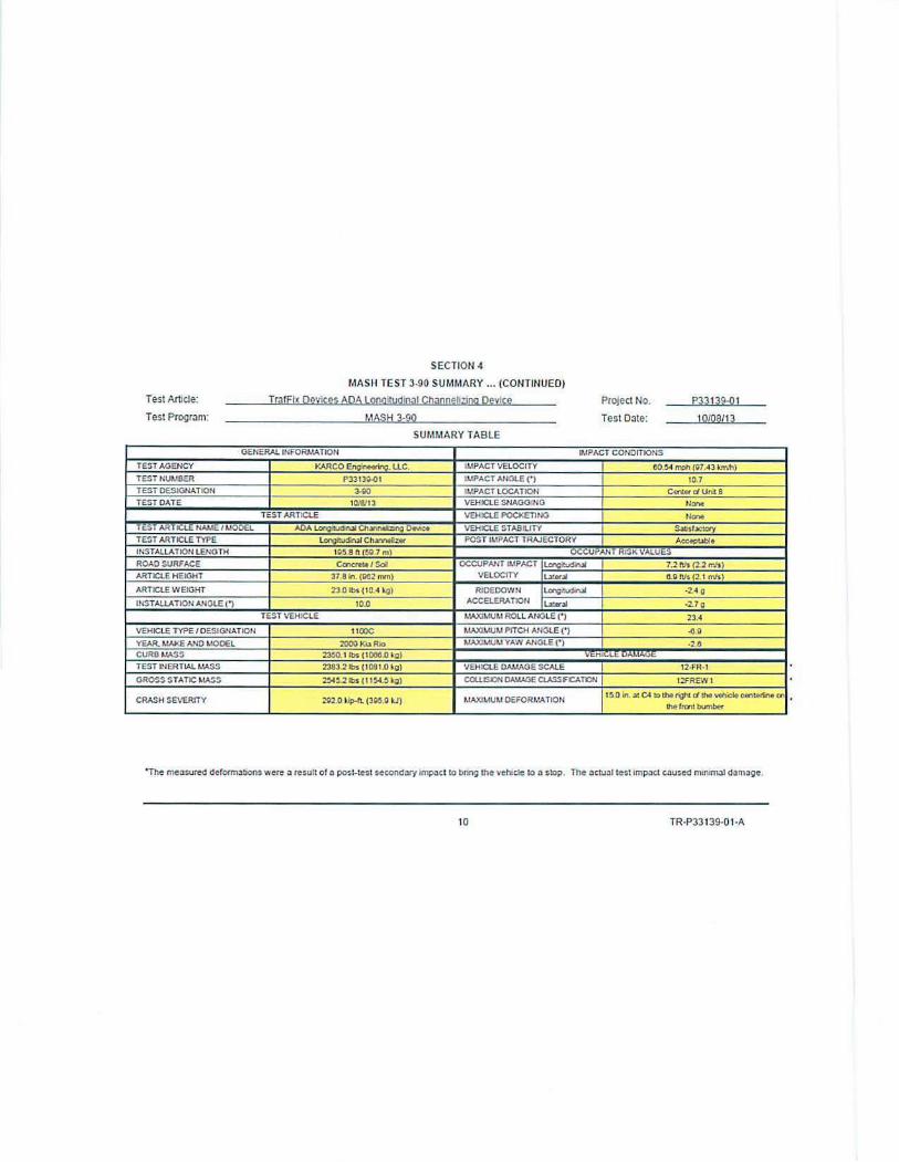
SECTION 4
MASH TEST J-91 SUMMARY bullbull (CONTINUED)
Test Article TraFlx Devices ADA Lonalludinal Channelzina Device Project No P33 140-01
Test Program MASH 3-91 Test Date 100813
SUMMARY TABLE
GENERAL INFORMATION IMPACT COtlDITIONS
TEST AGEtKY KARCO セN⦅NMLァ L Le - LIPACT VELOCITY 61 45 mh (Ga 80 lim1)
TEST NUMBER P33 140-()1 LIPACT ANGLE() 103
TEST DESIGNATION 3-Q1 LIPACT LOCATION CenlaquodUnlt8
TEST CATE tOta13 - V-HICLE SNAGGmG None-TEST ARTICLE VEHICLE POCKETING None middotshy
TEST ARTICLE tlAhE I MODEL adaセセoNNM VEHICLE STABILITY 5lliSfgtaay
TEST ARTICLE TYPE セ」セ POST IMPACT TRAJ ECTORY Aclteplgtble
InSTALLATION LENG TH I gl8 ft (597111) OCCUPANT RISK VALU ES
ROAD SURFACE Ccnq-Sol OCCUPANT IMPACT Lo-igilucngtI 0 8 fls (3 0 rrJs) -ARTICLE HEIGHT 378 on (Ile rrm) VELOCITY LnrU -shy -3l flfs 1-1 0mls)
ARTICLE W EIGHT 230 lbs t 104 i1 RIOEOOWN セ middot 17g
INSTALLATlON ANGLE ( ) t00 ACCELERATION lUDI M セ
Uo --shy -shyTEST VEHICLE LAXIMUM ROLL ANGLE() -4 1
VEHCLE TYPE I OESIGNATION 2270P LAXllUM PITCH ANGLE( ) -1-2
YEAR MAKE ANO MODEL セ Qodoe Rom_ llAXIMUM YAW ANGLE () -Z5
CURB MASS 48600 lbs (204 5 Ila) VEHICLE DAMAGE
TEST LlERTIAL MASS 4070Vlil (22545 kg) VEHICLE OMIAGE SCALE 12-fRmiddot I
GROSS STATIC MASS 40702 lbs (22545 kg)_ COWSlON DAMAGE CLASSFCATlON 12iilEW I
CRASH SEVERITY (lJ) 625Jl セイエN (06 lJ) LAXIMUM oセormation 03 Cl IOllgtt lolld tht C Cltn1nt en
Ch9 rnnt txrnblfr
10 TR-P33 t 40-01middotA
0
c
I I I I I I I I I I
セ i ⦅ ⦅ l
0
c
11I 111
11I 1 middot セN セA
セ LEGS IN
IOlf
セ
DEPLOYED POSfTON Urbanite Woll
__ deg セᄋNュ
SQE
B セZBᄚ カエエQ イ
owe NO Jr(V
57000UO A SHEE110r l
URBANITE WALL TYPICAL INSTALLATION
0
WARNING LIGHTS CAN BE MOUNTED (IF NEEDED
c C
SAND BAGS CAN BE ISEO FOR ADDED bauastofneededIセGMMセセセセセ⦅⦅NNNNNNNN⦅
Urbanite Wall Array
C-shy sセe OWG Nb REV0-Allllilllshy
B 500-176 A NOTES UNLESS OTHERWISE SPECIFIED degQ SHfEl bullOF 1
セQュセ
See DWG 500middot 118 ForAssembly
TrLE
bull e e 00
ebull 768
L1920 URBANITE WALL c cADA WALL
See DWG 5C0middot17P For Assembly
ADA URBANITE A
Foot Comparison
SuE oWG NO -
REV セCbullbullbull11shy11bull11bull
セ]McihuiGM-- _ti bullbull B 500-177 A
-degrtnbull 1HUl I CF ILamp1Tt
PEDESTRIAN SIDE
NON PEDESTRIAN SIDE
ADA WALL ARRAY
TrafFix Devices Inc Sl lEETNO DATE
I OF 2 21615
WARNING LIGHT
URBANITE WALL
SANDBAG
URBANITE WALL ARRAY
TrafFix
I OF 2 224 15
Devices Inc SHEET NO DATE
INTENDED USE
The Traffix Devices ADA Wall is a temporary work zone device designed to be an ADA compliant safety
device used to channelize g11ide and direct pedestrians through n safe pathway Individual wall sections arc
interconnected to each other to fom1 a continuous unobstnieted vertical wall The connected wall sections
arc designated with a pedestrian and non-pedesttian side On the pedestrian s ide there arc no tripping
hazards or gaps between the wall segments
The top surface provides a con tinuous smooth physical hnud contact rai l used for gui dance through a
pathway The bottom surface provides a detectable tapping surface used to tap a long cane by persons with
low vision to provide additional guidance in combinntion wi th the top hand guide surface The bottom
surface has minimal gaps to prevent canes from snagging but s till allows water to flow freely in the event of
a rainy condition
On the non-pedcsuian side there are two legs protniding outward used to support the wall segments
Ballast can be pl aced on the top of each leg to add stability to the walls i r needed In between the top and
bottom surfaces is the open middle section designed with ten individual segmented openings to allow
sc1v icc animals to see through the device and to minimjzc wind loading on the side surfaces
Tl1e ADA Vall is made from polyethylene mnterial and manufactured using a blow molding process The
blow molded polyethylene produces a durable component with high impuct resis tance nnd ideal for use in
extreme freezing conditions and extreme high temperature use
Ench ADA Wall is constrncted ofpolyethylene plastic and weighs approximately 230 lbs ( I 04 kg) The
ADA Wall measures 380 in (965 mm) tall 720 in ( 18 m) long and 30 in (76111111) wide Each ADA
Vall has a traffic side and a pedestrian side as shown in the accompanying drawing Each unit has two
(2) hinged legs constmcted from steel rubing located on the traffic side The legs provide s tabil ity and
suppott and can be ballas ted The units interlock by way of two (2) 125 in (32 mm) diameter plastic pins nt
one end that insert into two (2) mating banmiddotels on the opposite end which allow the units to hinge at each
connection Each ADA Wall nlso has provisions for attaching a banicadc light at each end
The ADA is designed to provide pedestrian guidance v itl1 as few as one wall section or an unlimited
number of sectious
CONT ACT INFORMATION
TraJFix Devices Inc Corporate Headquarters
160 A venida La Pata San Clemente CA 92673 wwwtraffixdevicescom
Phone + I (949)-36 1-5663 Fax + I (949)-361-9205
Email infotrafftxdev icescom
ADA WALL ARRAY
TrafFix SHEET NO DATE Devices Inc
2 OF2 2116115

0
c
I I I I I I I I I I
セ i ⦅ ⦅ l
0
c
11I 111
11I 1 middot セN セA
セ LEGS IN
IOlf
セ
DEPLOYED POSfTON Urbanite Woll
__ deg セᄋNュ
SQE
B セZBᄚ カエエQ イ
owe NO Jr(V
57000UO A SHEE110r l
URBANITE WALL TYPICAL INSTALLATION
0
WARNING LIGHTS CAN BE MOUNTED (IF NEEDED
c C
SAND BAGS CAN BE ISEO FOR ADDED bauastofneededIセGMMセセセセセ⦅⦅NNNNNNNN⦅
Urbanite Wall Array
C-shy sセe OWG Nb REV0-Allllilllshy
B 500-176 A NOTES UNLESS OTHERWISE SPECIFIED degQ SHfEl bullOF 1
セQュセ
See DWG 500middot 118 ForAssembly
TrLE
bull e e 00
ebull 768
L1920 URBANITE WALL c cADA WALL
See DWG 5C0middot17P For Assembly
ADA URBANITE A
Foot Comparison
SuE oWG NO -
REV セCbullbullbull11shy11bull11bull
セ]McihuiGM-- _ti bullbull B 500-177 A
-degrtnbull 1HUl I CF ILamp1Tt
PEDESTRIAN SIDE
NON PEDESTRIAN SIDE
ADA WALL ARRAY
TrafFix Devices Inc Sl lEETNO DATE
I OF 2 21615
WARNING LIGHT
URBANITE WALL
SANDBAG
URBANITE WALL ARRAY
TrafFix
I OF 2 224 15
Devices Inc SHEET NO DATE
INTENDED USE
The Traffix Devices ADA Wall is a temporary work zone device designed to be an ADA compliant safety
device used to channelize g11ide and direct pedestrians through n safe pathway Individual wall sections arc
interconnected to each other to fom1 a continuous unobstnieted vertical wall The connected wall sections
arc designated with a pedestrian and non-pedesttian side On the pedestrian s ide there arc no tripping
hazards or gaps between the wall segments
The top surface provides a con tinuous smooth physical hnud contact rai l used for gui dance through a
pathway The bottom surface provides a detectable tapping surface used to tap a long cane by persons with
low vision to provide additional guidance in combinntion wi th the top hand guide surface The bottom
surface has minimal gaps to prevent canes from snagging but s till allows water to flow freely in the event of
a rainy condition
On the non-pedcsuian side there are two legs protniding outward used to support the wall segments
Ballast can be pl aced on the top of each leg to add stability to the walls i r needed In between the top and
bottom surfaces is the open middle section designed with ten individual segmented openings to allow
sc1v icc animals to see through the device and to minimjzc wind loading on the side surfaces
Tl1e ADA Vall is made from polyethylene mnterial and manufactured using a blow molding process The
blow molded polyethylene produces a durable component with high impuct resis tance nnd ideal for use in
extreme freezing conditions and extreme high temperature use
Ench ADA Wall is constrncted ofpolyethylene plastic and weighs approximately 230 lbs ( I 04 kg) The
ADA Wall measures 380 in (965 mm) tall 720 in ( 18 m) long and 30 in (76111111) wide Each ADA
Vall has a traffic side and a pedestrian side as shown in the accompanying drawing Each unit has two
(2) hinged legs constmcted from steel rubing located on the traffic side The legs provide s tabil ity and
suppott and can be ballas ted The units interlock by way of two (2) 125 in (32 mm) diameter plastic pins nt
one end that insert into two (2) mating banmiddotels on the opposite end which allow the units to hinge at each
connection Each ADA Wall nlso has provisions for attaching a banicadc light at each end
The ADA is designed to provide pedestrian guidance v itl1 as few as one wall section or an unlimited
number of sectious
CONT ACT INFORMATION
TraJFix Devices Inc Corporate Headquarters
160 A venida La Pata San Clemente CA 92673 wwwtraffixdevicescom
Phone + I (949)-36 1-5663 Fax + I (949)-361-9205
Email infotrafftxdev icescom
ADA WALL ARRAY
TrafFix SHEET NO DATE Devices Inc
2 OF2 2116115
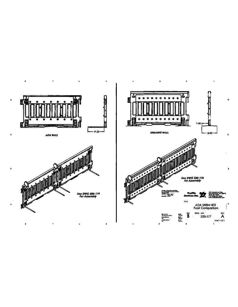