Embed Size (px)
Citation preview
NPS ARCHIVE1990.09ELKIN, L.
NAVAL POSTGRADUATE SCHOOL
Monterey , California
THESIS
r
CORROSION MECHANISMS AND BEHAVIOR OFA P-130X GR/6063 AL
COMPOSITE IN AQUEOUS ENVIRONMENTS
by
Leslie R. Elkin
September 1990
Thesis Advisor Indranath Dutta
Approved for public release; distribution is unlimited.

lclassiiied
urity classification of this page
REPORT DOCUMENTATION PAGE
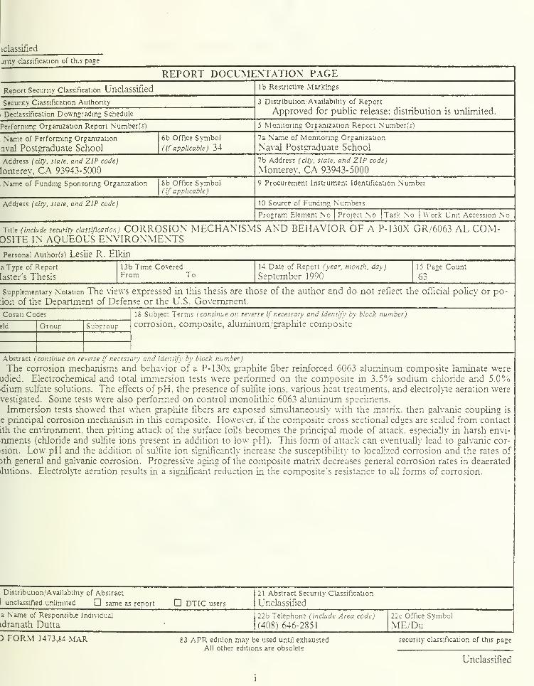
Report Security Classification Unclassified lb Restrictive Markings
Security Classification Authority
Declassification Downgrading Schedule
3 Distribution Availability of Report
Approved for public release; distribution is unlimited.
Performing Organization Report Number(s) 5 Monitoring Organization Report Number(s)
Name of Performing Organization
aval Postgraduate School
6b Office Symbol
(if applicable) 34
7a Name of Monitoring Organization
Naval Postgraduate School
Address (city, siate, and ZIP code)
lonterev, CA 93943-5000
7b Address (tin, state, and ZIP code)
Monterev, CA 93943-5000
Name of Funding/Sponsoring Organization 8b Office Symbol(if applicable)
9 Procurement Instrument identification Number
Address (city, slate, and ZIP code) 10 Source of Funding Numbers
Program Element No Project No Task No Work Unit Accession N
Title (include security classification) CORROSION MECHANISMS AND BEHAVIOR OF A P-130X GR/6063 AL COM-OSITE IN AQUEOUS ENVIRONMENTSPersonal Author(s) Leslie R. Elkin
a Type of Report
[aster's Thesis
13b Time CoveredFrom To
14 Date of Report (year, month, day)
September 1990
15 Page Count
63
Supplementary Notation The views expressed in this thesis are those of the author and do not reflect the official policy or po-
:ion of the Department of Defense or the U.S. Government.
Cosati Codes
eld Grouo Subsroup
18 Subject Terms i continue on reverse if necessary and identify by block number)
corrosion, composite, aluminum/graphite composite
Abstract (continue on reverse if necessary and identify by block number)
The corrosion mechanisms and behavior of a P-130x graphite fiber reinforced 6063 aluminum composite laminate were
udied. Electrochemical and total immersion tests were performed on the composite in 3.5% sodium chloride and 5.0%>dium sulfate solutions. The effects of pH, the presence of sulfite ions, various heat treatments, and electrolyte aeration werevestigated. Some tests were also performed on control monolithic 6063 aluminum specimens.
Immersion tests showed that when graphite fibers are exposed simultaneously with the matrix, then galvanic coupling is
e principal corrosion mechanism in this composite. However, if the composite cross sectional edges are sealed from contact
tth the environment, then pitting attack of the surface foils becomes the principal mode of attack, especially in harsh envi-
nments (chloride and sulfite ions present in addition to low pH). This form of attack can eventually lead to galvanic cor-
sion. Low pH and the addition of sulfite ion significantly increase the susceptibility to localized corrosion and the rates of
3th general and galvanic corrosion. Progressive aging of the composite matrix decreases general corrosion rates in deaerated
ilutions. Electrolyte aeration results in a significant reduction in the composite's resistance to all forms of corrosion.
Distribution/Availability of Abstract
unclassified, unlimited D same as report D DT1C users
21 Abstract Security Classification
Unclassified
a Name of Responsible Individual
idranath Dutta22b Telephone (include Area code)
(408) 646-2851
22c Office Symbol
ME/Du) FORM 1473,84 MAR 83 APR edition may be used until exhausted
All other editions are obsolete
security classification of this page
Unclassified

Approved for public release; distribution is unlimited.
Corrosion Mechanisms and Behavior of a P-130x Gr/6063 Al
Composite in Aqueous Environments
by
Leslie R. Elkin
Lieutenant, United States Navy
B.S., Purdue University, 1984
Submitted in partial fulfillment of the
requirements for the degree of
MASTER OF SCIENCE IN MECHANICAL ENGINEERING
from the
NAVAL POSTGRADUATE SCHOOLSeptember 1990
Anthony J. Healcy. Chairman.
Department of Mechanical Engineering
ABSTRACT
The corrosion mechanisms and behavior of a P-130x graphite fiber reinforced 6063
aluminum composite laminate were studied. Electrochemical and total immersion tests
were performed on the composite in 3.5% sodium chloride and 5.0% sodium sulfate
solutions. The effects of pH, the presence of sulfite ions, various heat treatments, and
electrolyte aeration were investigated. Some tests were also performed on control
monolithic 6063 aluminum specimens.
Immersion tests showed that when graphite fibers are exposed simultaneously with the
matrix, then galvanic coupling is the principal corrosion mechanism in this composite.
However, if the composite cross sectional edges are sealed from contact with the
environment, then pitting attack of the surface foils becomes the principal mode of attack,
especially in harsh environments (chloride and sulfite ions present in addition to low pH).
This form of attack can eventually lead to galvanic corrosion. Low pH and the addition of
sulfite ion significantly increase the susceptibility to localized corrosion and the rates of
both general and galvanic corrosion. Progressive aging of the composite matrix decreases
general corrosion rates in deaerated solutions. Electrolyte aeration results in a significant
reduction in resistance to all forms of corrosion.
hi
L-
TABLE OF CONTENTS
I. INTRODUCTION 1
A. CORROSION OF ALUMINUM ALLOYS-MECHANISMS AND BEHAVIOR..
2
B. CORROSION MECHANISMS AND BEHAVIOR OF MMCS 6
C. RESEARCH OBJECTIVES AND OVERVIEW 10
II. EXPERIMENTAL MATERIALS AND PROCEDURE 11
A. MATERIALS 11
B. SAMPLE PREPARATION AND ELECTRODE FABRICATION 13
1. Composite and 6063 Monolithic Aluminum 13
2. Graphite Fiber Electrodes 14
C. EXPERIMENTAL 14
1. Data Acquisition Equipment 14
2. Electrochemical Technique Parameters 15
a. Corrosion Potential Test Parameters 15
b. Galvanic Corrosion Test Parameters 15
c. Galvanodynamic Test Parameters 16
d. Polarization Resistance Test Parameters 16
e. Potentiodynamic Test Parameters 17
3. Behavior Study Tests 18
4. Immersion Tests 19
III. MECHANISM STUDY 20
A. RESULTS 20
1 . Immersion Tests 20
a. Edge Protected Samples 20
iv

b. Non Edge Protected Samples 26
2. Electrochemical Test Results 30
a. Polarization Test Plots 30
b. Polarization Test Micrographs 34
B. MECHANISM DISCUSSION 37
IV. EFFECT OF ENVIRONMENTAL AND MATERIAL VARIABLES 44
A. RESULTS 44
B. DISCUSSION 44
1. Corrosion Behavior in Deaerated Solutions 46
a. Effect of pH 46
b. Effect of Sulfite Ion Presence 47
c. Effect of Heat Treatment 48
2. Corrosion Behavior in Aerated Solutions 49
V. CONCLUSIONS 51
REFERENCES 53
INITIAL DISTR BUTION LIST 56

I. INTRODUCTION
Today's technology demands the development of new materials offering better
performance, increased reliability, and adherence to stringent property requirements. An
important class of materials considered to fall into this category is composites. A
composite is formed when two or more constituents are combined on a macroscopic scale.
This new material is designed to combine the best features of each constituent by
maximizing certain material properties. [Ref. 1]
Composite materials generally consist of a high strength or high modulus
reinforcement combined with a bulk material, called the matrix. The reinforcement, which
may be in the shape of particles, whiskers, or fibers, is the component that carries the
major stresses and loads, while the matrix allows the transfer of these stresses and loads to
the fiber. Composite materials can be divided into three broad groups based upon the
matrix material: metal, ceramic, or plastic. [Ref. 2]
Metal matrix composites are promising materials for use in structural or dynamic
applications because they can take advantage of the many superior material properties of
both the matrix and the reinforcement. These advantages include the combination of the
following properties: [Ref. 2]
• High specific strength and modulus• High toughness and impact properties
• High electrical and thermal conductivity
• Excellent reproducibility of properties
A particular metal matrix composite (MMC) widely used today consists of an
aluminum matrix and a graphite fiber reinforcement. Aluminum and its alloys are of
interest to the industrial and scientific communities because of their strength and formability
combined with low density, their good thermal and electrical conductivities, and their
1
ability to resist corrosion [Ref. 3]. Graphite fibers possess both a high modulus of
elasticity and a high thermal conductivity. The proper combination of aluminum and
graphite to form a MMC should produce a new material which has high stiffness and
strength, good ductility, and high thermal conductivity. [Ref. 4]
The Naval Weapons Support Center, Crane, Indiana has chosen a 6063 aluminum
alloy reinforced with 27 volume percent P130-X continuous graphite fibers as a potential
candidate for use in electronic module frames because of its low density, high stiffness,
and high thermal conductivity. The combination of these key properties is necessary as
weight, vibration reduction, and heat removal are all potentially limiting design factors. In
his master's thesis [Ref. 4], LT King proposed composite elastic modulus and thermal
conductivity values determined from the rule of mixtures. The analysis indicates that by
forming this composite monolithic 6063 aluminum's elastic modulus is raised more than
threefold and its thermal conductivity by almost twofold. These results indicate that
combining 6063 aluminum and P130-X graphite fibers gives a composite capable of
meeting the high stiffness and thermal conductivity demands of advanced electronic module
frames.
In addition to processing, performance, and material property studies, an evaluation of
this MMCs resistance to corrosive marine environments is necessary.
A. CORROSION OF ALUMINUM ALLOYS-MECHANISMS AND
BEHAVIOR
The thermodynamic stability of aluminum in water is commonly expressed by the
potential-pH diagram which was devised by Pourbaix and is shown in Fig. 1 [Ref. 5,6].
This diagram delineates regions in which corrosion of aluminum is likely to occur.
Aluminum forms a passive oxide barrier or exhibits immunity in the other regions. For
example, deviations in pH above or below the range of 4 to 9 results in a shift from a

LUI
<Uui
UJQO
qUJ>
UJ -
"J 21< UJ
h- e>
20uj q:(- oo >-
CL IQ<z:<h-
1.2
I 1 1 I 1 1 1
0.6CORROSION
-
0.4 -
PASSIVATION-
0.4 CORROSION ~
0.8 —
1.2 ^ -
1.6 -
-2
IMMUNITY "*\^^2.4
1 ! 1 1 1 1 1 >^-2 6 8
PH
10 16
Figure 1: Pourbaix diagram for aluminum in H2O at 25 degrees Celsius.
regime in which pitting will be the predominate mode of corrosion to one in which general
corrosion predominates.
When exposed to the atmosphere, aluminum immediately forms an adherent and
'complete' oxide layer. Upon immersion in water, this film grows to some equilibrium
thickness depending on several factors which include temperature and pH. In
environments of near neutral pH, defects in the oxide film may lead to a pitting mode of
corrosion. Aluminum is very susceptible to this form of attack, but at the same time shows
good resistance to general corrosion.
Pitting is not only the most common form of attack in aluminum, but it is also the most
insidious. Preferential pitting attack occurs at defects in the oxide film usually due to
surface inclusions. Inside the pit, aluminum ions are hydrolyzed raising the acidity within
the pit and causing further pit propagation. As this process proceeds a cap of various
aluminum oxides and hydroxides forms over the pit eventually blocking its operation
[Ref. 6]. The chloride ion and other halides play a significant role in this process [Ref. 7].
In marine environments, the primary corrosive ingredient is chloride ion. Sea water
contains various salts, in addition to NaCl, amounting to approximately 3.5% by weight of
sea water. In order to simplify and standardize laboratory experiments in which sea water
testing is to be done, an aqueous 3.5% NaCl solution is often used. This is necessary to
help eliminate all the possible complicating variables introduced by the vast number of ionic
species present in sea water. [Ref. 4]
Besides those species which are naturally occurring in sea water, some man-made
species are also of concern. For example, ships use fuels containing varying amounts of
sulfur. During combustion, sulfur in the fuels forms sulfur dioxide (SO2) and sulfur
trioxide (SO3). When these mix with the moist environment they form sulfuric and

sulfurous acids. Of these, sulfurous acid is the most serious corrosive material and can
exist in a variety of concentrations depending upon fuel sulfur content, power setting, and
other factors. [Ref. 8]
Many researchers [Ref. 9,10,11,12] have studied the interaction between passive
aluminum films, ions present in solution, and pitting susceptibility. While a mechanism
describing the propagation of pitting has been generally accepted, there exists no clear
understanding of how pitting is initiated. Isaacs [Ref. 9] states: "The processes which
occur in the passive layer which are directly responsible for its breakdown and the onset of
localized corrosion are at present unclear." He goes on to suggest some possible causes as:
adsorption, penetration, passive film solubility, perturbation events, and vacancy
clustering. The apparent bottom line is that two things are necessary to initiate pitting: (1)
an aggressive anion and (2) particular heterogeneities in the metal. Isaacs concluded that in
aluminum breakdown and repassivation occur at the same point in the passive film. Tan
and Chin [Ref. 10] determined that anodic polarization of 6061-T6 aluminum in neutral
sodium sulfate solutions resulted in passivation of the material with no pitting. But, with
the gradual addition of chloride ion passivity was destroyed. Above about 100 ppm
chloride ion adc pits began to form and increased in size and density with increasing
chloride ion concentration.
In their background study, Elboujdaini et. al. [Ref. 11] referenced various research
discussing the effect that chloride and sulfate ions have on passive oxide film stability.
This research indicated that the ionic resistance of the passive oxide film is lowered when
chloride ions are present and get included at certain selected locations in the film. Sulfate
ions, on the other hand, do not get included in the film and, as a result, there is no harmful
effect on film resistance. Other research [Ref. 12] has shown that immersion of many
aluminum alloys, including alloy 6061, in 1000 ppm cerium chloride for one week
markedly improves their resistance to localized corrosion. A conclusion of this research
was that the use of rare earth chlorides as media for passivation is worth evaluating.
Crevice and galvanic corrosion are two other important corrosion modes in aluminum
alloys, in addition to general and pitting corrosion. The mechanism of crevice corrosion is
the same as that for pitting, in general. It is autocatalytic in nature, occurs in very localized
regions, and requires mobility differences between ionic species to operate. In sodium
chloride solutions, aluminum in contact with most other metals, will corrode preferentially.
Aluminum becomes the anode and cathodically protects the metal connected to it. The
degree to which aluminum corrodes when coupled to a more cathodic metal depends on the
area ratio of the couple, the degree to which the aluminum is polarized, and the electrolyte.
If aluminum must be coupled to a more cathodic metal, the most desirable arrangement
would be to have a large aluminum to small cathode area ratio. When coupled to
aluminum, some metals will polarize the aluminum sufficiently to cause it to exceed its
pitting potential. Galvanic corrosion will be accelerated in electrolytes containing halide
salts, aeration, and plenty of cathodic reactant. [Ref. 5]
B . CORROSION MECHANISMS AND BEHAVIOR OF MMC'S
Because of their dual nature, metal matrix composites are susceptible to three adverse
processes: galvanic coupling of the matrix and the reinforcement, crevice attack at the
matrix/reinforcement interface, and preferred localized attack at structural and compositional
inhomogeneities within the metal matrix [Ref. 13].
Some knowledge of the various MMC fabrication techniques and the problems
encountered in them is necessary before considering possible corrosion processes in
MMCs. For instance, fibers are sometimes reactive or nonwetting [Ref. 14] with the
molten matrix material and must be coated to make the fibers wettable and limit fiber
reactivity. If this coating is imperfect, the effect on material properties may be deleterious.
Carbides, oxides, or intermetaJlics may form at matrix/reinforcement interfaces during high
temperature processing. Vastly different thermal expansion coefficients between the matrix
and the reinforcement can result in large thermal residual stresses upon cooling [Ref. 4].
These and other processing artifacts can result in additional corrosion beyond that listed
above and due to the simple combination of matrix and reinforcement.
Traditional descriptions of corrosion behavior include material weight loss, thickness
reduction, and pit depth [Ref. 15]. Some weight loss experiments [Ref. 15,16] done on
MMCs indicate that this approach may need some revision. In some cases, especially with
graphite/aluminum MMCs, these researchers saw initial composite weight gain from the
oxide formed and trapped during the corrosion process. As a result, tests which give
weight loss results are potentially inappropriate and should be reserved for qualitative
judgements only.
Vassilaros et. al. [Ref. 15] performed a qualitative study of the corrosion behavior of
two different types of VSB-32 graphite 6061 aluminum MMCs. They found that when
excessive exposure to a marine environment was allowed, pitting initiated on the surface
foils and propagated to the graphite/aluminum interfaces. The aluminum corrosion product
formed in the pit blistered the MMC. In their marine environment exposure studies, edge
protection was used on some samples in order to elucidate various corrosion behaviors.
This protection consisted of a coating applied only on surfaces with both matrix and
reinforcement exposed. The samples without edge protection experienced much more
severe corrosion than those with edge protection.
Additional qualitative studies of the corrosion behavior of MMCs have been
conducted. Pfeifer [Ref. 16] studied the marine atmospheric corrosion of Thornel-50
graphite fiber 201 and 202 aluminum MMCs. He found that corrosion, once initiated,
continued preferentially along foil interfaces and between wires. This type of attack was
more rapid than attack along the fiber/matrix interfaces. Aylor and Kain [Ref. 17J tested
various silicon carbide and graphite/aluminum MMCs in marine environments. They found
that for the graphite/aluminum composites tested, exposed edges resulted in blistering and
exfoliation of the aluminum surface foils. The primary corrosion mode in silicon
carbide/aluminum MMCs was pitting occurring at the matrix/reinforcement interfaces. In
their status report on the corrosion of aluminum matrix composites, Metzger and Fishman
[Ref. 18] reviewed past corrosion data and summarized their observations. They
concluded that the types of corrosion seen in marine atmosphere studies was a result of
imperfect consolidation of the composite including possible inadequate fiber wetting during
infiltration of the fiber bundle. It appeared that well-bonded composites exhibited better
corrosion resistance.
To date, the majority of MMC corrosion testing has been conducted in the laboratory
under closely controlled conditions. More testing is necessary, however, because there are
some questions that remain unanswered. The goals of the tests conducted thus far have
been twofold. First, to describe how a composite will behave when environmental
parameters are altered. And, second, to understand the principal modes of corrosion
leading to degradation of a composite's material properties.
While some researchers have concluded that galvanic corrosion plays a major role in
the accelerated corrosion of graphite/aluminum and graphite/magnesium MMCs, about an
equal number have not. In her study of the corrosion behavior of graphite/magnesium
MMCs, Trzaskoma [Ref. 19] determined that galvanic coupling plays an important role in
the aqueous corrosion of graphite/magnesium composites. Vassilaros et. al. [Ref. 15] in
their marine environment corrosion study of VSB-32 graphite 6061 aluminum composites,
likewise determined that galvanic coupling was the dominant corrosion mechanism. Yet
another group [Ref. 20] claimed that galvanic coupling in a graphite/aluminum composite

between the Thornel 50 graphite fibers and the 6061 aluminum alloy promoted crevice
corrosion at the fiber/matrix interface.
These conclusions indicating the importance of galvanic coupling between the matrix
and the reinforcement conflict with the conclusions of other researchers. For example, in
two of their papers, Aylor and Moran [Ref. 21,22] concluded that galvanic corrosion
between graphite fibers and the aluminum matrix is not the predominant reason for
accelerated corrosion in graphite/aluminum composites. Instead, the accelerated attack is
caused by some kind of segregation (or compound formation) at the fiber/matrix interfaces.
In another study by Hihara and Latanision [Ref. 23] exfoliation of a P100 graphite fiber
6061 aluminum composite was shown to be more destructive than classical galvanic
corrosion. The exfoliation was observed to be a result of the formation of pits in the
diffusion bond regions caused by microstructural chloride containing zones.
Crevice attack at the matrix/reinforcement interface and preferred localized attack
within the metal matrix have been found to be important in both graphite/aluminum
composites and other MMCs. Sedriks et. al. [Ref. 24] used electrochemical techniques to
study the corrosion behavior of boron/aluminum MMCs and found that crevice attack at the
interface was the principle reason for the higher corrosion rate of the composite versus the
unreinforced alloy. In the study mentioned above by Hihara and Latanision [Ref. 23], the
graphite/aluminum composite was polarized to 2.0 Volts versus a saturated calomel
electrode (SCE) in a deaerated 0.5M sodium sulfate solution at pH 7. Crevices were found
to form under these conditions along the perimeters of the graphite fibers. The crevice
formation was determined to be a result of the graphite oxidizing to carbon dioxide.
Preferred localized attack at microstructural inhomogeneites has been deemed
important in certain cases. In the same research discussed above, Hihara and Latanision
[Ref. 23] blame the titanium-boron chemical vapor deposition (Ti-B CVD) composite
9
fabrication process for allowing residual microstructural chlorides to become trapped within
the diffusion bond regions. Severe pitting was observed to coincide with the diffusion
bond regions causing the precursor wires to disbond. Trzaskoma et. al. [Ref. 25] studied
the effects of silicon carbide on pit initiation susceptibility for three silicon
carbide/aluminum alloy composite systems in sodium chloride solutions. They found that
pitting potentials and hence the pitting susceptibilities of the composites were not much
different from those of the unreinforced alloy. In a more recent study, Trzaskoma
[Ref. 26] determined that pits initiated at secondary particles within the matrix of a silicon
carbide/5456 aluminum alloy. It was shown that these particles were intermetallic phases
composed of alloying elements Mg, Cr, Mn, Fe, and Al.
C. RESEARCH OBJECTIVES AND OVERVIEW
There were two primary objectives in this investigation of the aqueous corrosion of a
P-130x graphite/6063 aluminum composite. First, to characterize the composite's
corrosion behavior in an aqueous 3.5% sodium chloride solution while varying solution
pH and aeration, matrix heat treatment, and the presence of sulfite ion. And second, to
understand the fundamental mechanism or mechanisms of corrosion in this composite in
both 3.5% sodium chloride and 5.0% sodium sulfate solutions. Both electrochemical and
immersion tests were employed in this research.
The experimental materials and procedures used will be detailed before discussing the
results of both the mechanism and behavior studies.
10
II. EXPERIMENTAL MATERIALS AND PROCEDURE
A. MATERIALS
The P-130x graphite fibers used both in the fabrication of the composite and in this
research as electrode material for galvanic corrosion testing were obtained from Amoco
Performance Products, Richfield, Connecticut. The fibers are experimental as the Y in P-
130x indicates and are roughly 10-12 mm in diameter. They are continuous throughout the
composite, but their cross-sectional shape, while nominally circular, is predominantly
irregular due to difficulty in fabrication. The fibers obtained directly from Amoco came in a
spool-wound 2000 fiber tow, with no twist.
The control monolithic 6063 aluminum used in this research was obtained from
ALCOA as extruded angle stock in the -Tl (overaged) temper.
The composite was fabricated by DWA Composites, Chatsworth, California.
Fabrication was by a proprietary method which involved coating the 2000 fiber tow using
the Titanium Boron chemical vaper deposition (Ti-B CVD) method and infiltrating the
coated fiber tow with molten 6063 aluminum to form precursor wires. The precursor wires
were then layed out in alternating 0° and 90° biases between two layers of 6063 aluminum
foils. This "sandwich" was then diffusion bonded to form the final 0-90 cross-plied
continuous fiber composite. The as-received composite was determined to be in the
overaged condition. Figure 2 shows an optical micrograph of a composite cross-section.
Between the two surface foils (top and bottom) are eight alternating layers of graphite
fiber/6063 aluminum diffusion bonded precursor wires. The only exception in this
composite is that the center two (of the eight alternating) layers of precursor wires are
1 1

Figure 2: Optical micrograph of a composite edge revealing longitudinal and transverse
fiber layers and composite surface foils (top and bottom). (50X)
1 2

aligned parallel to each other. The finished product was supplied in sheets 0.15 m long,
and 0.0015 m thick.
B . SAMPLE PREPARATION AND ELECTRODE FABRICATION
1 . Composite and 6063 Monolithic Aluminum
Specimens for most of the electrochemical tests were cut into disks 0.015 m in
diameter. This was accomplished for both the monolith and the composite by electric
discharge machining using a brass electrode. The monolithic metal electrodes used in the
galvanic corrosion runs were machined to a 0.0151 m by 0.020 m by 0.003 m rectangular
slab, and then tapped to accept the specimen holder rod on one of the 0.0151 m by 0.003 m
faces. Immersion tests were conducted on coupons of composite material measuring 0.014
meters long by 0.007 meters wide by 0.0015 meters thick.
Immediately prior to all experiments, the monolith and composite specimens were
wet sanded to 600 grit on SiC paper. With the composite, this was done most carefully, to
avoid perforation of the surface foil. The specimens were then rinsed in tap water followed
by a distilled water rinse, an ethanol rinse, and then dried under a hot air gun. Certain
polarization and immersion tests required that the exposed specimen surface be polished.
In all cases the specimens used in these tests were first polished on a 6 (im diamond
paste wheel (after 600 grit SiC paper) followed by a 3 |im and 1 |im diamond paste
polishing.
As part of the mechanism study, samples were viewed in the SEM and/or light
microscope after testing. The procedure for cleaning these samples was as follows. First,
a rubber stopper was rubbed back and forth (under running tap water) across the exposed
surface to remove the majority of the corrosion products. Second, the samples were rinsed
in distilled water and ethanol and then dried under a hot air gun. Additional corrosion
products were removed by stirring the sample in a beaker of 70% nitric acid for about two
13

to three minutes according to NACE Standard TM-01-69 [Ref. 27]. Finally, the samples
were again rinsed in tap water, then distilled water and ultrasonically cleaned in ethanol.
2 . Graphite Fiber Electrodes
Graphite fiber electrodes were required as the second working electrode in the
galvanic corrosion experiments along with the monolithic aluminum slabs. They were
constructed by soldering to an electrical connector both a length of graphite fiber tow and
an isulated copper wire. The wire, with attached length of graphite fiber tow, was then
pulled through a 0.10 m length of Vycor tubing until about a 0.015 m length of fibers were
left protuding from the opposite end of the tube. The end of the tube with graphite fibers
left protruding was plugged with a slow-curing epoxy. At the other end of the tube, some
of the excess wire was secured to the outside top of the tube with electrical tape to prevent
any movement of the soldered junction. To complete the assembly, the free end of the wire
and the wire end of the glass tube were fed through the hole in a rubber stopper. The
schematic drawing of a similar graphite electrode assembly can be found in LT King's
master thesis [Ref. 4].
C. EXPERIMENTAL
1 . Data Acquisition Equipment
An EG&G Princeton Applied Research (PAR) Corporation Model 351 Corrosion
Measurement System was used in all electrochemical tests. This system was comprised of
a PAR Model 1000 System Processor connected through a parallel interface to a single
PAR Model 273 Potentiostat/Galvanostat. The PAR Model K47 Corrosion Cell was
connected through an electrometer to the Model 273. The addition of an RE0093 Plotter
rounded out the corrosion measurement system used here. A detailed description of the
Model 351 Corrosion Measurement System can be found in the system's operating manual
[Ref. 28].
14
2 . Electrochemical Technique Parameters
There are eleven experimental techniques already set up and stored in the system
software. These techniques may be used with the default parameters or may be modified
by the operator. The techniques are listed in Reference 28, p. II-2. In this study,
potentiodynamic, polarization resistance, galvanodynamic, galvanic corrosion, and
corrosion potential techniques were used. The parameters chosen for each technique in this
study will be summarized in the remainder of this section. The sample used in each test,
except the galvanic corrosion runs and some polarization tests, was a disk held in the K105
flat specimen holder. This arrangement results in exactly 0.0001 m2 (or 1 cm2) of exposed
surface area to the electrolyte. Exceptions to this sample geometry will be noted in the
appropriate sections.
a. Corrosion Potential Test Parameters
The only parameter controlled by the operator for this measurement is time.
In general, 24 hours was a sufficient length of time to allow stabilization of the specimen's
corrosion potential, Ecorr . Curve smoothing choices available to the operator are: no
smoothing, seven point smoothing, and 15 point smoothing. Seven point smoothing was
used in all of the ele trochemical tests.
b . Galvanic Corrosion Test Parameters
The monolithic 6063 aluminum slabs presented a surface area of 0.0008 m2
to the electrolyte. As in the corrosion potential tests, 24 hours was usually a sufficient
length of time for stabilization of the galvanic corrosion potential (Ega iv ) to occur. The
same was true for the stabilization of the galvanic corrosion current density, igalv-
The graphite area fraction utilized in all galvanic corrosion runs was 0.40.
This was accomplished by trimming excess fiber tow from the ends of the graphite fiber
electrodes such that the appropriate exposed area ratio between graphite and monolithic
15
aluminum was established. Refer to Reference 4, Appendix C for detailed calculations
leading to the necessary exposed length of graphite fiber.
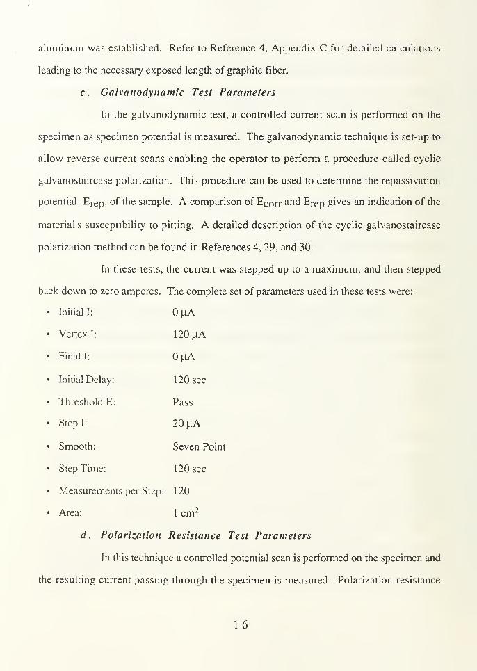
c . Galvanodynamic Test Parameters
In the galvanodynamic test, a controlled current scan is performed on the
specimen as specimen potential is measured. The galvanodynamic technique is set-up to
allow reverse current scans enabling the operator to perform a procedure called cyclic
galvanostaircase polarization. This procedure can be used to determine the repassivation
potential, Erep, of the sample. A comparison of Ecorr and Erep gives an indication of the
material's susceptibility to pitting. A detailed description of the cyclic galvanostaircase
polarization method can be found in References 4, 29, and 30.
In these tests, the current was stepped up to a maximum, and then stepped
back down to zero amperes. The complete set of parameters used in these tests were:
• Initial I: |iA
• Vertex I: 120(iA
• Final I: |iA
• Initial Delay: 120 sec
• Threshold E: Pass
• Step I: 20 ^lA
• Smooth: Seven Point
• Step Time: 120 sec
• Measurements per Step: 120
• Area: 1 cm2
d. Polarization Resistance Test Parameters
In this technique a controlled potential scan is performed on the specimen and
the resulting current passing through the specimen is measured. Polarization resistance
16
plots developed from this method provide a means of determining the corrosion current
density, icorr- [Ref. 28: pp. VII 29-37]
The complete set of parameters used in these tests were:
Initial E: 20 mV below ECOrr
Final E: 20 mV above ECOrr
Initial Delay: 3600 sec
Scan Rate: 0.01 mV/sec
Density: 2.7 g/cm3
Area: 1 cm2
Smooth: Seven Point
IR Compensation: Disabled
e. Potentiodynamic Test Parameters
This technique was used entirely in support of the mechanism studies. The
corrosion characteristics of monolithic 6063 aluminum, composite surface foils, and
composite cross sections in various electrolytes were determined and compared using this
technique. A vast amount of information can be obtained from the current-potential
relationship developed with this method. This data can be used to determine Ecorr , icom
Tafel slopes, and other important electrochemical information.
All three sample types tested were polished to a 1 |im finish using the sample
preparation process outlined in part B of this chapter. The corrosion measurement system
alignment for these tests was identical to that used in the other electrochemical tests. The
flat specimen holder was also used in all tests. This presented no problem for the
monolithic aluminum and composite surface foil samples, but for the composite cross
section samples a modification to the sample's geometry was necessary. This was done by
'sandwiching' the composite between two hemispherical halves of Teflon and using slow-
17
cure epoxy to bond the sample between the two halves of Teflon. A disk-shaped specimen
was obtained using this procedure. The exposed sample surface area in composite cross
section tests was 0.000016 m2 (or 0.16 cm2).
The potential scans were all initiated at a potential sufficiently below the
corrosion potential, Ecorr , so that well-defined cathodic slopes could be generated. The
complete set of parameters used in these tests were:
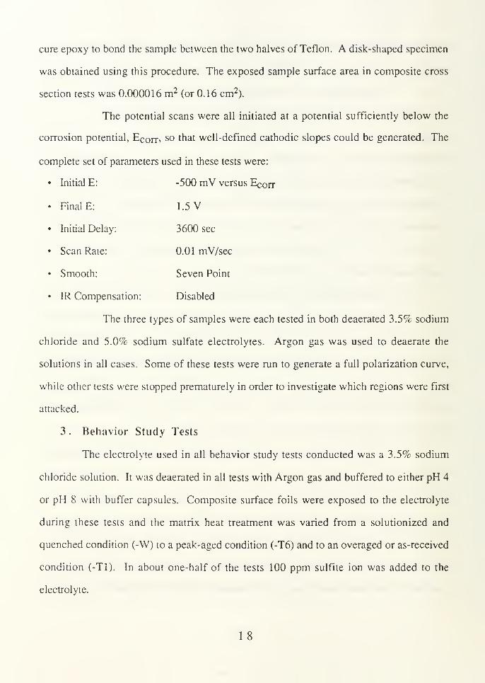
Initial E: -500 mV versus Ecorr
Final E: 1.5 V
Initial Delay: 3600 sec
Scan Rate: 0.01 mV/sec
Smooth: Seven Point
IR Compensation: Disabled
The three types of samples were each tested in both deaerated 3.5% sodium
chloride and 5.0% sodium sulfate electrolytes. Argon gas was used to deaerate the
solutions in all cases. Some of these tests were run to generate a full polarization curve,
while other tests were stopped prematurely in order to investigate which regions were first
attacked.
3 . Behavior Study Tests
The electrolyte used in all behavior study tests conducted was a 3.5% sodium
chloride solution. It was deaerated in all tests with Argon gas and buffered to either pH 4
or pH 8 with buffer capsules. Composite surface foils were exposed to the electrolyte
during these tests and the matrix heat treatment was varied from a solutionized and
quenched condition (-W) to a peak-aged condition (-T6) and to an overaged or as-received
condition (-T1). In about one-half of the tests 100 ppm sulfite ion was added to the
electrolyte.
1 8
Ecorr* Erep> icorr. igalv> and Ega iv were measured for each combination of
matrix heat treatment, pH, and presence or absence of sulfite ion. Analytical grade sodium
chloride and 10 Megaohm-cm distilled water were used to prepare the solutions. Behavior
study results and discussion are given in Chapter IV.
4 . Immersion Tests
Solutions used in this testing were prepared in the same manner as described in
the above section. Two types of tests were conducted in this portion of the mechanism
study. The first type of test involved samples with only their surface foils exposed to the
electrolyte, and in the second type of test, one polished composite edge and both surface
foils were exposed. A thin run of slow-cure epoxy was applied to the composite edges
which required protection.
Three immersion baths were prepared for the surface foil tests. All were aqueous
3.5% sodium chloride solutions. Two of the three were titrated to pH 4 with hydrochloric
acid and the remaining bath was titrated to pH 8 with sodium hydroxide. To one of the pH
4 baths, 1000 ppm sulfite ion was added. The samples were immersed for 10 weeks,
removed, and cleaned following the procedure outlined above prior to micrography.
Four samples with one polished edge exposed to the electroyte were immersed in
3.5% sodium chloride and 5.0% sodium sulfate solutions. Immersion test run times were
two and fourteen days. Two of the samples were immersed in the 3.5% sodium chloride
electrolyte, one for two days and one for 14. The remaining two samples were immersed
in 5.0% sodium sulfate, one for two days and one for 14. Exposed composite cross
sections tested in this manner were also cleaned using the method outlined above.
19

III. MECHANISM STUDY
A. RESULTS
1 . Immersion Tests
a. Edge Protected Samples
A low magnification (1 IX) micrograph of the three edge sealed immersion
samples (after ten weeks immersion and before cleaning) can be seen in Figure 3. The top
coupon was immersed in a 3.5% sodium chloride solution which was titrated to pH 8 with
sodium hydroxide. The two bottom samples were also immersed in 3.5% sodium
chloride, but they were titrated to pH 4 with hydrochloric acid. 1000 ppm sulfite ion was
added to the electrolyte in which the bottom left sample was immersed.
Both samples immersed in the pH 4 electrolytes formed a thick, white,
hydrated oxide film (probably hydrargillite, Al203«3H20) [Ref. 5] within one week versus
relatively little formation on the sample immersed in the pH 8 electrolyte.
A closer look at the surface foil of the sample (after cleaning) which was
immersed in the pH 8 electrolyte reveals no indication of pitting after ten weeks. Figure 4
shows a SEM micrograph (53 IX) of a general surface foil region. The appearance of the
protective oxide film on this sample can be described as being porous.
The low magnification (1 IX) micrograph presented in Figure 5 was taken of
the sample which was immersed in the pH 4 electrolyte containing no sulfite ion. This
micrograph (taken after the sample was cleaned) reveals the relative location of pits which
were observed under the SEM. A representative pit from this sample can be seen in Figure
6. Again, the oxide film on this sample in the area surrounding the pit has a porous
appearance identical to that seen on the pH 8 specimen. The pits in this specimen's surface
20

Figure 3: Low magnification micrograph ( 1 IX) of the three edge sealed immersionsamples after ten weeks immersion (and before cleaning).
Figure 4: SEM micrograph of an edge protected sample immersed for ten weeks in 3.5%sodium chloride (titrated to pH 8). Taken after cleaning. (53 IX)
2 1

Figure 5: Stereomicroscope micrograph of an edge protected sample immersed for ten
weeks in 3.5% sodium chloride (titrated to pH 4). Taken after cleaning. (1 IX)
Figure 6: SEM micrograph of an edge protected sample immersed for ten weeks in 3.5%sodium chloride (titrated to pH 4). Taken after cleaning. (53 IX)
22

.
foil correspond to the widely spaced black spots (of varying diameter) seen in Figure 5. A
region in the bottom of the pit shown in Figure 6 has been blown up and can be seen in
Figure 7. Crystallographic facets are clearly visible in this SEM micrograph. Trzaskoma
[Ref. 26] observed the same crystallographic behavior in pits formed on 5456 and 6061
aluminum alloys in sodium chloride solutions. This behavior is typical for aluminum and
the faceting probably results from preferential etching of the { 100} planes [Ref. 26].
Shown in Figure 8 is a low magnification (11X) micrograph of the sample
which was immersed in the pH 4 electrolyte containing 1000 ppm sulfite ion (after
cleaning). A comparison of Figure 8 to Figure 5 reveals that the addition of sulfite ion at
pH 4 results in an increase in the surface foil pit density. The numerous, small black spots
covering the surface of this specimen correspond to pits as seen under the SEM. Shown in
Figure 9 is a representative pit from the surface of this specimen. A typical pit in this
specimen measured 20 to 25 microns in diameter, compared to a diameter of 60 to 70
microns for a typical pit in the sample immersed in the pH 4 electrolyte containing no sulfite
ion.
The protective oxide film in the region surrounding the pit shown in Figure 9
can be seen to have a dimpled appearance. This is in contrast to the porous appearance of
the oxide layer formed on the surfaces of the pits immersed in both pH 4 and pH 8
electrolytes containing no sulfite. A high magnification blow up of a region in the bottom
of the pit seen in Figure 9, can be seen in Figure 10. The same crystallographic faceting
can be observed in this micrograph as in the micrograph in Figure 7.
23

Figure 7: This SEM micrograph is a high magnification (2.87kX) blow-up of the bottom
of the pit seen in Figure 6.
Figure 8: A stereomicroscope micrograph of an edge protected sample immersed for ten
weeks in 3.5% sodium chloride (titrated to pH 4 and with 1000 ppm sulfite ion
added). (1 IX)
24
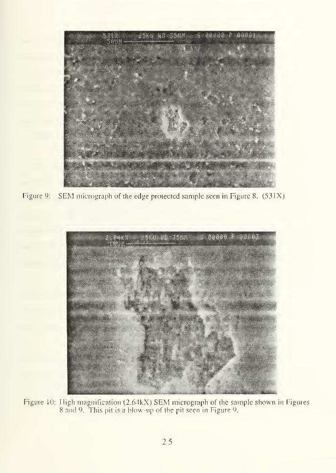
Figure 9: SEM micrograph of the edge protected sample seen in Figure 8. (53 IX)
Figure 10: High magnification (2.64kX) SEM micrograph of the sample shown in Figures
8 and 9. This pit is a blow-up of the pit seen in Figure 9.
2 5
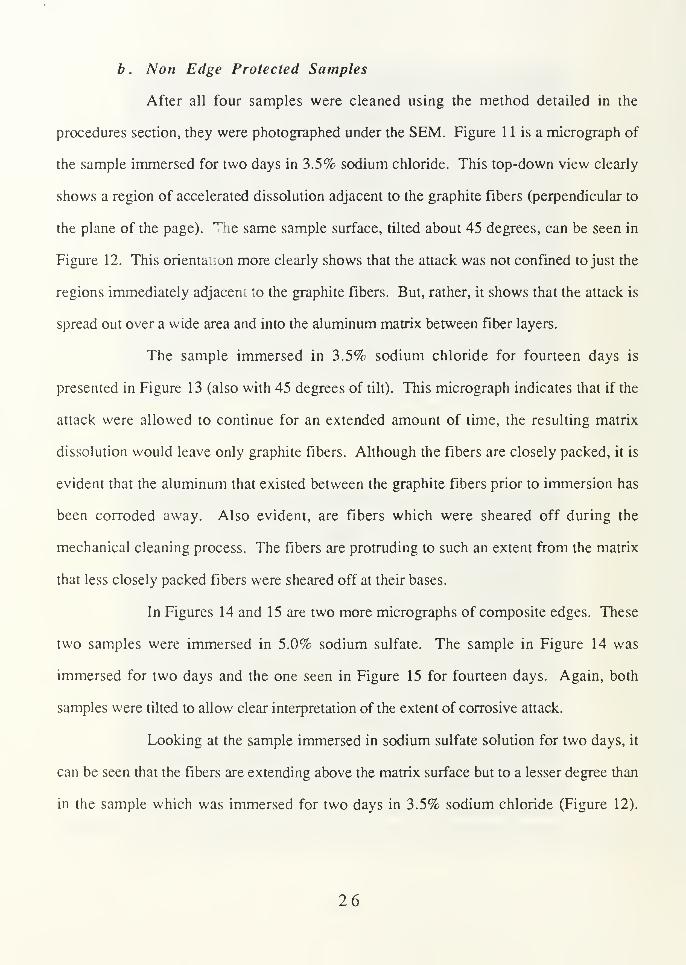
b . Non Edge Protected Samples
After all four samples were cleaned using the method detailed in the
procedures section, they were photographed under the SEM. Figure 1 1 is a micrograph of
the sample immersed for two days in 3.5% sodium chloride. This top-down view clearly
shows a region of accelerated dissolution adjacent to the graphite fibers (perpendicular to
the plane of the page). The same sample surface, tilted about 45 degrees, can be seen in
Figure 12. This oriental.on more clearly shows that the attack was not confined to just the
regions immediately adjacem to the graphite fibers. But, rather, it shows that the attack is
spread out over a wide area and into the aluminum matrix between fiber layers.
The sample immersed in 3.5% sodium chloride for fourteen days is
presented in Figure 13 (also with 45 degrees of tilt). This micrograph indicates that if the
attack were allowed to continue for an extended amount of time, the resulting matrix
dissolution would leave only graphite fibers. Although the fibers are closely packed, it is
evident that the aluminum that existed between the graphite fibers prior to immersion has
been corroded away. Also evident, are fibers which were sheared off during the
mechanical cleaning process. The fibers are protruding to such an extent from the matrix
that less closely packed fibers were sheared off at their bases.
In Figures 14 and 15 are two more micrographs of composite edges. These
two samples were immersed in 5.0% sodium sulfate. The sample in Figure 14 was
immersed for two days and the one seen in Figure 15 for fourteen days. Again, both
samples were tilted to allow clear interpretation of the extent of corrosive attack.
Looking at the sample immersed in sodium sulfate solution for two days, it
can be seen that the fibers are extending above the matrix surface but to a lesser degree than
in the sample which was immersed for two days in 3.5% sodium chloride (Figure 12).
26
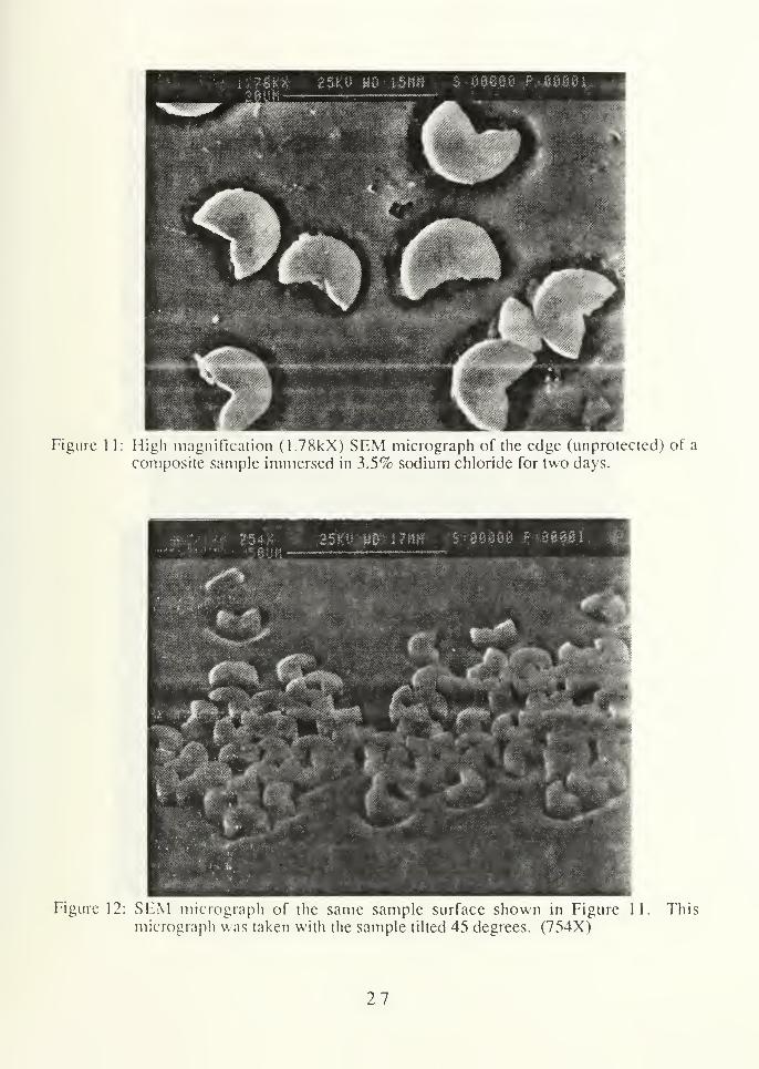
Figure 1 1: High magnification (1.78kX) SEM micrograph of the edge (unprotected) of a
composite sample immersed in 3.5% sodium chloride for two days.
Figure 12: SEM micrograph of the same sample surface shown in Figure 11.
micrograph was taken with the sample tilted 45 degrees. (754X)This
27

Figure 13: SEM micrograph of an unprotected edge sample immersed in 3.5% sodiumchloride for 14 days. The sample is tilted 45 degrees. (735X)
_jg#»F**
< .:^.&&^VP& :" '" '
Figure 14: SEM micrograph of an unprotected edge sample immersed in 5.0% sodiumsulfate for two days. The sample is tilted 45 degrees. (769X)
28

Figure 15: SEM micrograph of an unprotected edge sample immersed in 5.0% sodium
sulfate for 14 days. The sample is tilted 45 degrees. (769X)
29

Another noticeable feature about the corrosive attack on the surface of this sample is that
there is a slight dip in matrix elevation in the regions immediately adjacent to the fibers.
After fourteen days, the sample shown in Figure 15 has suffered severe
corrosive attack of the same order as that sustained by the sample immersed for fourteen
days in sodium chloride. It does appear, however, that the extent of attack is slightly
greater in the sample immersed in sodium chloride. Another result common to all four edge
exposed immersion samples is the fact that graphite fiber diameters remained constant no
matter what th jxposure length.
2 . Electrochemical Test Results
a. Polarization Test Plots
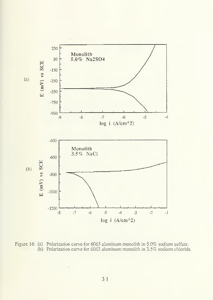
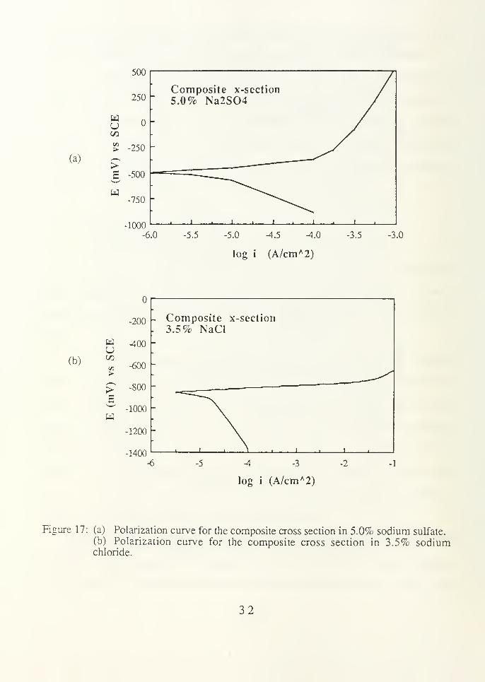
Of the six full polarization tests conducted, the results of bur are shown in
Figures 16 and 17. Table 1 gives the pertinent electrochemical data derived from these
polarization plots. The data from two other plots, which are not shown, is also included in
the table.
There are many key points which can be generated from these plots and from
Table 1. First, the shape of the anodic regions in the four plots indicates that sodium
sulfate is passivating to the monolith and the composite cross section while sodium chloride
is not. The Tafel slopes, 8a and 6C , were determined from the anodic and cathodic
polarization legs of the respective plots and entered in Table 1. A comparison of these
slopes also indicates that sodium chloride is a far more aggressive electrolyte than sodium
sulfate. For instance, 6a increases from 19.5 mV/decade for the monolith in sodium
chloride to 492 mV/decade for the monolith in sodium sulfate.
Another key point is that the corrosion current density (icorrX and therefore
the corrosion rate, is greater for the composite cross section than for the composite surface
foil or the monolith in both sodium chloride and sodium sulfate electrolytes. Also, iCorr for
30
(a)
u
>
U
250"
50"
-150
-350 "
-550 F
-750
-950
Monolith5.0% Na2S04
-7 -6
log i (A/cm A2)
-5 A
(b)U
B
-400
-600 -
-800
-1000
-1200
Monolith3.5% NaCl
-7 -5 -4 -3
log i (A/cm A2)
.?
Figure 16: (a) Polarization curve for 6063 aluminum monolith in 5.0% sodium sulfate.
(b) Polarization curve for 6063 aluminum monolith in 3.5% sodium chloride.
31
(a)
500
250
wuCO
> -250
>E -500
U3-750
-1000
Composite x-section
5.0% Na2S04
-6.0 -5.5 -5.0 -4.5 -4.0
log i (A/cm A2)
-3.5 -3.0
(b)
wu
>
>
-
200 - Composite x-section
3.5% NaCl
400
-600
-800
•looo h
-1200
-1400
-6 -5 -4 -3
log i (A/cm A2)
-1
Figure 17: (a) Polarization curve for the composite cross section in 5.0% sodium sulfate,
(b) Polarization curve for the composite cross section in 3.5% sodiumchloride.
32

3CO
<
>1—1
c1—1—
o
ooCNoo
1
oOOr-
Oi
-3-
ooCN
ONr-
i
or—
*
to
CO
<
oo
CNCO
co
oCOin o"
co
dCN
£
<
6
"5t
oqo ^
mno
O
COT—
I
oo
oCO
CD
0)a>c6
CO.
coom
ooNO
oCM<3-
CN^3"
o<ua>£
CQ.
in
inoCNcs
pCOoo
CO
CO
inON
CNOn
Material/Exposed
Surface/Electrolyte
ooonO
sisi
u
=300
"53
O cd
6S
oo TTSO
"c/a ^O BCX o£ S3o «U 8
1o
3oo
<u
8PC °°C CNO C3
u z
Uz
.i"ocos
O00CN03
z
ii"oco3
33
the cross section in sodium chloride is approximately two and one-half times greater than in
sodium sulfate (Table 1). The remaining icorr's were foundto be very close to each other.
The corrosion potential values found in tests conducted in the sodium sulfate electrolyte
are, in general, considerably noble to those found in tests conducted in the sodium chloride
electrolyte.
The exchange current density (i ) is yet another important electrochemical
parameter which can be generated from these tests. The iG values given in Table 1 are for
the hydrogen reduction reaction. From Table 1, it can be seen that the io's determined from
the composite surface foil and monolith polarization tests in sodium chloride are on the
order of lO 8 A/cm2. This is about 2 orders of magnitude less than the remaining iG values.
For instance, iQ found for the composite surface foil in sodium chloride is about 140 times
less than the i found for the composite cross section in sodium chloride. The only
variable changed between these two tests was that graphite fibers were exposed
simultaneously with matrix in the cross section test.
This last result will be considered in the mechanism discussion section along
with a superposition of the four polarization plots.
b . Polarization Test Micrographs
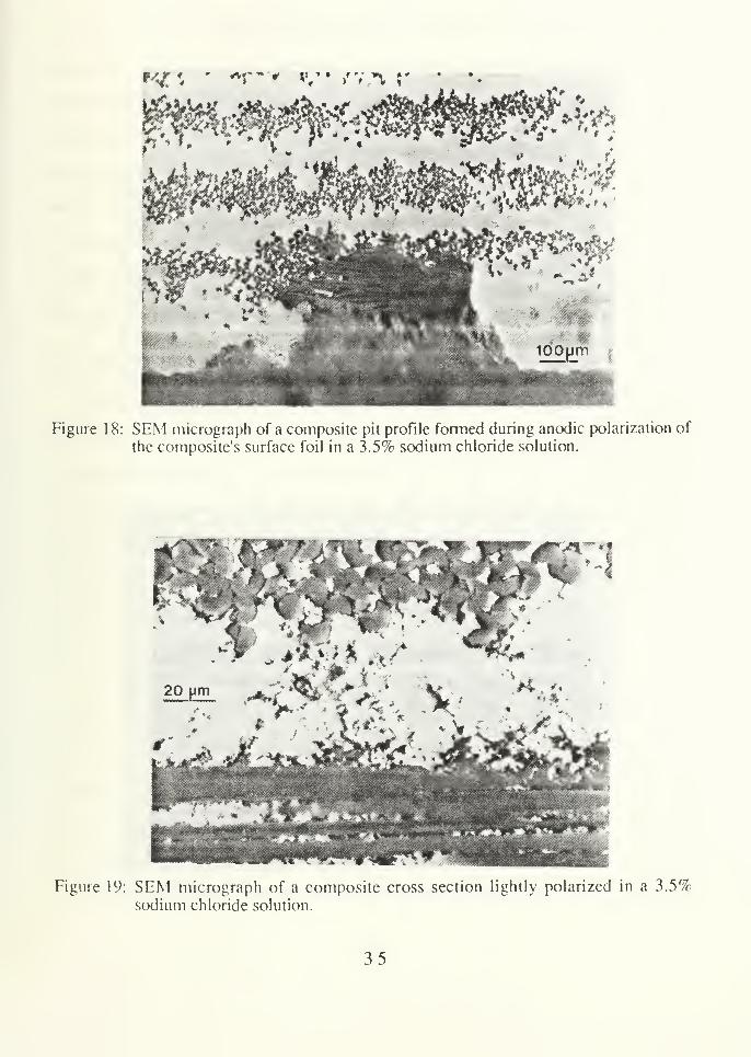
Figure 1 8 shows a SEM micrograph of a composite pit profile which formed
during anodic polarization of the composite's surface foil in 3.5% sodium chloride. Upon
close examination, it can be seen that the matrix metal within regions of high fiber density
is attacked preferentially. Also apparent, is the fact that once the pit has propagated to the
underlying fiber layer, matrix dissolution proceeds rapidly along the longitudinal fiber
direction. These results suggest either galvanic coupling or localized crevice corrosion at
the interface and in regions of high fiber packing.
34
**f* '"* <y • /va ?'
•J 4
Figure 1 8: SEM micrograph of a composite pit profile formed during anodic polarization of
the composite's surface foil in a 3.5% sodium chloride solution.
Figure 19: SEM micrograph of a composite cross section lightly polarized in a 3.5%sodium chloride solution.
35
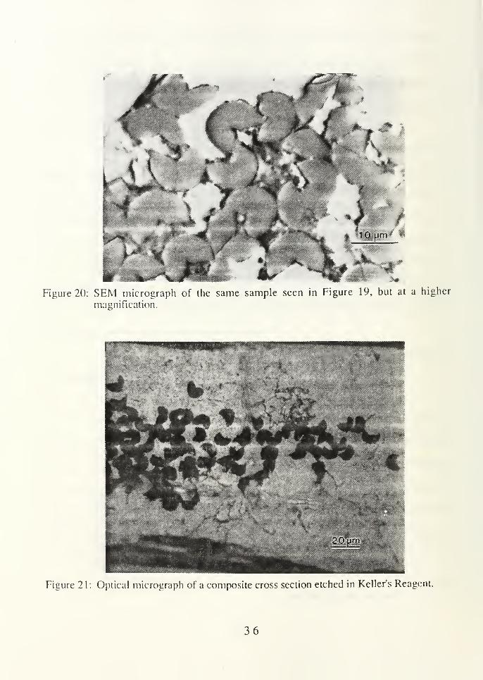
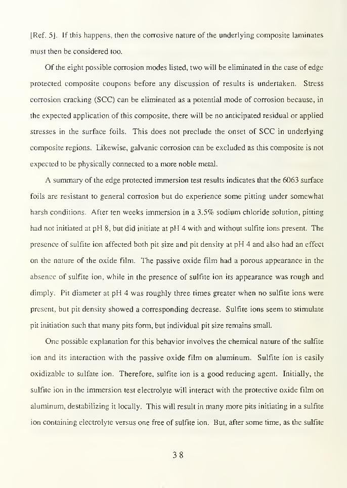
Figure 20: SEM micrograph of the same sample seen in Figure 19, but at a higher
magnification.
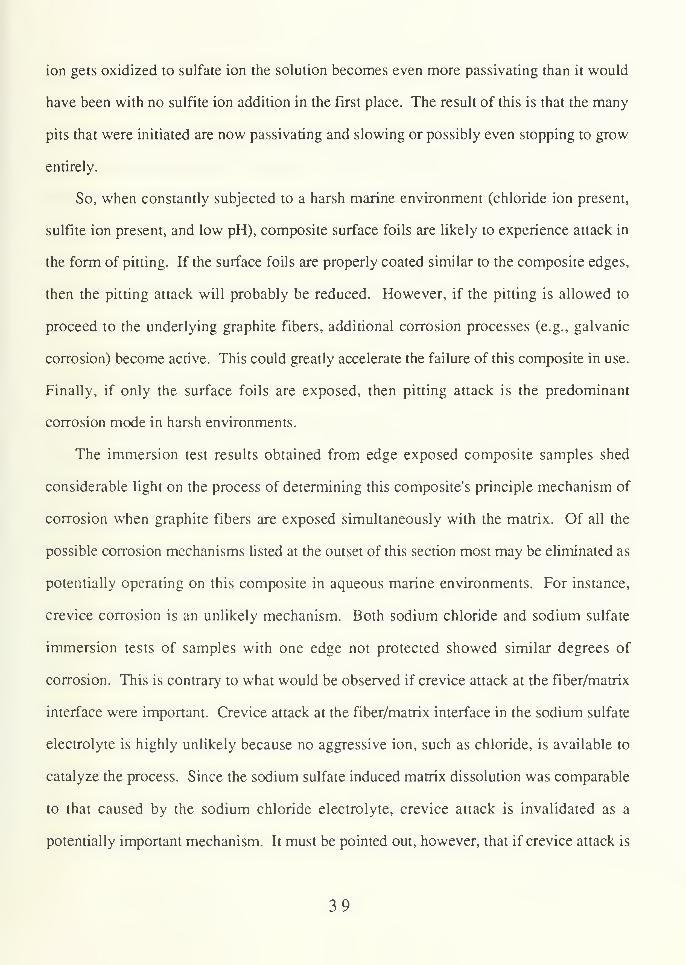
Figure 21 : Optical micrograph of a composite cross section etched in Keller's Reagent.
36

SEM micrographs were also taken of a composite cross section
which was anodically polarized (lightly) in 3.5% sodium chloride. These micrographs
appear in Figures 19 and 20. They indicate that initial attack upon anodic polarization of
composite cross sections occurs at fiber/matrix interfaces (Figure 20) and at localized
regions between fiber layers (Figure 19). As shown in Figure 21, a composite cross
section etched in Keller's Reagent shows localized attack similar to that observed in Figure
19. Apparantly, upon anodic polarization, areas which are first attacked include all high
energy regions-both at the fiber/matrix interface and at what are likely microstructural
segregations at grain boundaries in the matrix between fiber layers.
B. MECHANISM DISCUSSION
The task of establishing the principal corrosion mode(s) in aqueous environments for
this MMC is complicated. Multiple corrosion modes are potentially superimposed or
convoluted simultaneously. Therefore, a careful and comprehensive testing and evaluation
scheme is necessary in order to decouple possibly overlapping effects. The corrosion
modes most likely to be important in this MMC are galvanic coupling of the aluminum
matrix with the graphite reinforcement, crevice attack at the fiber/matrix interface, and
localized attack at structural and compositional inhomogeneities within the metal matrix
[Ref. 13].
While these corrosion modes may arise due to the addition of graphite fibers to the
aluminum matrix, the standard corrosion modes affecting aluminum alloys alone may also
become important in this MMC. For example, if the edges of a composite coupon are all
sealed, then only the surface foils will be exposed to the marine environment or electrolyte.
In this case, general corrosion, pitting attack, stress corrosion cracking, galvanic corrosion,
and corrosion fatigue of the surface foils would be the potential principal modes of
corrosion in this composite unless, of course, the integrity of the surface foils is violated
37
[Ref. 5J. If this happens, then the corrosive nature of the underlying composite laminates
must then be considered too.
Of the eight possible corrosion modes listed, two will be eliminated in the case of edge
protected composite coupons before any discussion of results is undertaken. Stress
corrosion cracking (SCC) can be eliminated as a potential mode of corrosion because, in
the expected application of this composite, there will be no anticipated residual or applied
stresses in the surface foils. This does not preclude the onset of SCC in underlying
composite regions. Likewise, galvanic corrosion can be excluded as this composite is not
expected to be physically connected to a more noble metal.
A summary of the edge protected immersion test results indicates that the 6063 surface
foils are resistant to general corrosion but do experience some pitting under somewhat
harsh conditions. After ten weeks immersion in a 3.5% sodium chloride solution, pitting
had not initiated at pH 8, but did initiate at pH 4 with and without sulfite ions present. The
presence of sulfite ion affected both pit size and pit density at pH 4 and also had an effect
on the nature of the oxide film. The passive oxide film had a porous appearance in the
absence of sulfite ion, while in the presence of sulfite ion its appearance was rough and
dimply. Pit diameter at pH 4 was roughly three times greater when no sulfite ions were
present, but pit density showed a corresponding decrease. Sulfite ions seem to stimulate
pit initiation such that many pits form, but individual pit size remains small.
One possible explanation for this behavior involves the chemical nature of the sulfite
ion and its interaction with the passive oxide film on aluminum. Sulfite ion is easily
oxidizable to sulfate ion. Therefore, sulfite ion is a good reducing agent. Initially, the
sulfite ion in the immersion test electrolyte will interact with the protective oxide film on
aluminum, destabilizing it locally. This will result in many more pits initiating in a sulfite
ion containing electrolyte versus one free of sulfite ion. But, after some time, as the sulfite
38
ion gets oxidized to sulfate ion the solution becomes even more passivating than it would
have been with no sulfite ion addition in the first place. The result of this is that the many
pits that were initiated are now passivating and slowing or possibly even stopping to grow
entirely.
So, when constantly subjected to a harsh marine environment (chloride ion present,
sulfite ion present, and low pH), composite surface foils are likely to experience attack in
the form of pitting. If the surface foils are properly coated similar to the composite edges,
then the pitting attack will probably be reduced. However, if the pitting is allowed to
proceed to the underlying graphite fibers, additional corrosion processes (e.g., galvanic
corrosion) become active. This could greatly accelerate the failure of this composite in use.
Finally, if only the surface foils are exposed, then pitting attack is the predominant
corrosion mode in harsh environments.
The immersion test results obtained from edge exposed composite samples shed
considerable light on the process of determining this composite's principle mechanism of
corrosion when graphite fibers are exposed simultaneously with the matrix. Of all the
possible corrosion mechanisms listed at the outset of this section most may be eliminated as
potentially operating on this composite in aqueous marine environments. For instance,
crevice corrosion is an unlikely mechanism. Both sodium chloride and sodium sulfate
immersion tests of samples with one edge not protected showed similar degrees of
corrosion. This is contrary to what would be observed if crevice attack at the fiber/matrix
interface were important. Crevice attack at the fiber/matrix interface in the sodium sulfate
electrolyte is highly unlikely because no aggressive ion, such as chloride, is available to
catalyze the process. Since the sodium sulfate induced matrix dissolution was comparable
to that caused by the sodium chloride electrolyte, crevice attack is invalidated as a
potentially important mechanism. It must be pointed out, however, that if crevice attack is
39

present in the sodium chloride electrolyte, then its severity is negligible compared to the
principal corrosion mechanism.
If localized attack were the primary mechanism, then again, the vast majority of the
matrix dissolution would have been concentrated in very small areas (either in the matrix
between fiber layers or immediately adjacent to the fibers) and not spread out over the
whole matrix surface as was observed in these tests. Specifically, interfacial attack, attack
at compositional inhomogeneities, pitting, and graphite fiber oxidation can be ruled out as
possible important mechanisms. The first three of these can be discounted as unimportant
because of the widespread nature of the matrix dissolution. If these three do exist, then
their effects are masked by a much more important mechanism. Graphite fiber oxidation
can be ruled out because fiber diameter remained unchanged for the duration of the
immersion testing.
The widespread matrix dissolution seen here is not a result of general corrosion. It
was shown in the last section that general corrosion of the surface foils was rendered
neglible by the formation of a protective oxide film over a large pH range. The same
protective oxide film was not observed to form on the matrix in the unprotected edge tests.
Also, in both two day immersion tests, the matrix immediately adjacent to the graphite
fibers was observed to have undergone greater corrosion than elsewhere. This is another
indication that general or uniform attack can be eliminated as important. Since the
aluminum matrix material is no different than the composite surface foils, the only possible
explanation for the widespread matrix attack is galvanic coupling between the graphite
fibers and the aluminum matrix. This coupling effect hinders the aluminum's ability to
form an oxide film and results in dissolution of the aluminum matrix. The four elements
required for galvanic attack are certainly present. Specifically, these elements are the anode
(the 6063 aluminum matrix), the cathode (the graphite fibers), the electrical connection
40
between them (they are in physical contact), and the electrolyte. So, the principal initiating
corrosion mode on a completely unprotected composite is expected to be galvanic coupling.
Electrochemical test results confirm the conclusion that galvanic coupling between the
graphite reinforcement and the aluminum matrix is the principal mode of corrosion in this
composite when the edges are unprotected or when a pit propagates to an underlying fiber
layer. A definitive way of evaluating the influence of the graphite fibers in the matrix is to
overlay the Tafel slopes (obtained during the polarization studies) on a single plot and
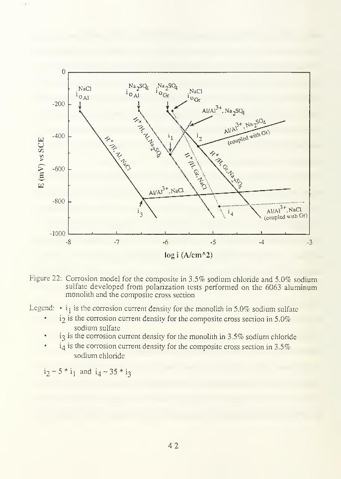
notice the shift in icorr to increasing current densities when gTaphite fibers are present.
This schematic is presented in Figure 22.
The first point borne out by the plot shown in Figure 22 concerns the relative
magnitudes of the exchange current density of hydrogen reduction, iG . As indicated in the
results section, io for a composite surface foil or for the monolith in 3.5% sodium chloride
was significantly increased when both aluminum matrix and graphite fibers were exposed
to the electrolyte. This suggests that the substrate for the cathodic reaction changes from
aluminum to graphite when graphite fibers are exposed in conjunction with aluminum,
increasing i and icorr- The exchange current density increase is attributed to the hydrogen
reduction reaction ccurring on the exposed graphite fibers (as they are more noble to
aluminum) as opposed to occurring on the aluminum matrix. If the hydrogen reduction
reaction were to continue on the aluminum matrix instead of the simultaneously exposed
graphite fibers, then there would have been no coupling between the aluminum and the
graphite and as a result no shift in i would have been observed.
Corrosion current densities associated with cross section exposed samples are
considered galvanic corrosion current densities (igalv's) in this analysis. As seen in Figure
22, a shift to greater corrosion current densities was seen in both the sodium chloride and
the sodium sulfate electrolytes. The same relative shift was observed when the composite
41
-200 -
-400 -
UCO
> -600
-800 -
1000
NaCl Na2S04 Na
2S04
NaCl
AiyAl3+
,NaCl
(coupled with Gr)
-6 -5
logi (A/cm A2)
-3
Figure 22: Corrosion model for the composite in 3.5% sodium chloride and 5.0% sodiumsulfate developed from polarization tests performed on the 6063 aluminummonolith and the composite cross section
Legend: • ij is the corrosion current density for the monolith in 5.0% sodium sulfate
• 12 is the corrosion current density for the composite cross section in 5.0%
sodium sulfate
i3 is the corrosion current density for the monolith in 3.5% sodium chloride
i4 is the corrosion current density for the composite cross section in 3.5%
sodium chloride
12-5*1! and i4~ 35 *
i3
42

surface foil data were overlayed on the cross section data. Slight differences in the Tafel
slopes and iQ values add up to the significant shift in corrosion current densities. This
consistent trend of increasing current densities from iCOrr to igalv lends additional support
to the conclusion that galvanic coupling is important in this composite.
The polarization results indicating the regions of initial matrix dissolution as being
localized do not run contrary to the theory of galvanic coupling. These results simply show
that upon light anodic polarization specific high energy regions are subject to attack first.
This can be explained on the basis of anodic and cathodic rates of reaction and how they are
affected by anodic polarization. Upon anodic polarization, the anodic reaction rate is raised
depending upon the magnitude of Ba . High energy interfaces and zones (such as surface
precipitates and grain boundary particles) will be the first regions affected. At the same
time, the cathodic reaction rate is reduced. As the degree of polarization is raised, the
anodic and cathodic reaction rates become more separated (from their value at the free
corrosion potential, Ecorr). This will result in a masking of the effect of galvanic coupling
which is a process that will only occur to its fullest extent at the free corrosion potential.
In summary, a variety of tests were devised to show that galvanic coupling in this
composite is important (in aqueous environments). Polarization studies and immersion
tests were used. A careful and comprehensive analysis of the results of these tests
including generous application of the principles of electrochemical theory has provided the
means of elucidating the role of galvanic corrosion.
43

IV. EFFECT OF ENVIRONMENTAL AND MATERIALVARIABLES
A. RESULTS
The complete set of behavior study data can be seen in parts (A), (B), and (C) of Table
2. Results given in parts (A) and (B) of the table were obtained with the 3.5% sodium
chloride electrolyte deaerated. Part (C) of the table contains the results obtained by LT J.
D. King in his master's thesis [Ref. 4]. The behavior data tabulated here is from testing
conducted with an aerated 3.5% sodium chloride electrolyte. All solutions were buffered to
either pH 4 or pH 8 as indicated in the second column of each part of the table. The matrix
heat treatment of the composite tested is listed in the leftmost column.
B. DISCUSSION
The effect of changing environmental and material variables (pH, presence or absence
of sulfite ions, matrix heat treatment, and electrolyte aeration) on the corrosion behavior
parameters (Ecorr , Erep, icorr> igalv> and Egaiv ) will be discussed here. And, since these
behavior parameters are directly linked to pitting susceptibility, and general and galvanic
corrosion rates, the discussion will primarily focus on how these three key measures of
corrosion are affected by changes in one of the environmental or material variables.
Because the analysis of the corrosion behavior of this composite is a complicated process,
it will be split into an analysis of the composite's behavior in aerated and deaerated
solutions, where the cathodic half-cell reactions, and hence the corrosion mechanisms,
might be considerably different.
44

TABLE 2
(A) ELECTROCHEMICAL TEST RESULTS IN 3.5% NaCl (DEAERATED)
Heat Treatment Electrolyte pH Ecorr Erep icorr igalv Egalv
-Tl 8 -950 -807 0.115 0.870 -860
-T6 8 -945 -811 0.529 0.844-W 8 -910 -804 0.972 0.568 -868
-Tl 4 -811 -803 0.704 2.975 -806-T6 4 -805 -799 1.56 -788
-W 4 -810 -799 3.10 1.625 -785
(B) ELECTROCHEMICAL TEST RESULTS IN 3.5% NaCl (100 PPM SULFITE ION
ADDED AND DEAERATED)
Heat Treatment Electrolyte pH Ecorr Erep icorr igalv Egalv
-Tl 8 -821 -808 0.236 0.217 -806
-W 8 -837 -810 1.24 0.230 -768
-Tl 4 -797 -812 20.7 6.63 -804
-W 4 -804 -813 29.4 7.94 -766
(C) ELECTROCHEMICAL TEST RESULTS IN 3.5% NaCl (AERATED)
Heat Treatment Electrolyte pH Ecorr Erep icorr igalv Egalv
-Tl 8 -775 -771 13.6 85 -770
-W 8 -795 -744 4.39 40 -750
-Tl 4 -766 -764 41.1 350 -760
-W 4 -751 -768 15.1 250 -730
Units: Ecorr , Erep, and Egaiv measured in mV; icorr and igalv measured in fiA/cm2
45

1 . Corrosion Behavior in Deaerated Solutions
a. Effect of pH
Results based on pH effect are valid for all three heat treatments and sulfite
ion presence unless otherwise noted. The effects of heat treatment and sulfite ion addition
will be treated separately in subsequent sections. As seen in Tables 2(A) and 2(B), ECOrr is
more noble at pH 4 than at pH 8, and it is also evident that a change in pH between 8 and 4
has little or no effect on Erep. The combination of these two results implies that the surface
foils have good resistance to pitting at pH 8 because Erep is considerably more
electropositive than Ecorr . However, at pH 4 the surface foil is less resistant to pitting
because Ecorr is almost equal to Erep (in other words, a slight fluctuation in Ecorr may
cause Ecorr to go greater than Erep resulting in the inability of previously existing pits to
repassivate). When sulfite ions are added, Ecorr becomes electropositive to Erep at pH 4
making the surface foil considerably more susceptible to pitting. The probability of pitting
is greater with sulfite ions present because none of the pits can repassivate. These results
correlate with immersion test results.
When pH drops from 8 to 4, as seen in Tables 2(A) and 2(B), ic0rr increases
probably due to passive film breakdown at pH 4. Referring to the Pourbaix diagram
shown on page 3, the region of passivity of aluminum in pure water has its leftmost margin
at pH 4. Therefore, in sodium chloride electrolytes, it is likely that this region of passivity
will shrink, resulting in the oxide film becoming less stable at pH 4 than it would be if in
pure water-thus causing the greater icorr values at pH 4 than at pH 8. Ega iv shows the
same trend as ECOrr i.e., at pH 4 Egaiv is more noble than at pH 8. At any given pH, heat
treatment, or sulfite ion presence, Ega iv is electropositive relative to ECOrr since galvanic
coupling polarizes the aluminum electropositively. Galvanic corrosion current density
46

(igalv) increases at pH 4, following the same trend as icon- The rates of both galvanic and
general corrosion are greater at pH 4 than at pH 8.
With sulfite ions present, a change in pH from 8 to 4 has no effect on Egaiv
(Table 2(B)). Although this is apparently contrary to what was found in the absence of
sulfite ions (Table 2(A)), a close examination suggests that this is actually consistent with
what is expected, as elucidated below. In the absence of sulfite ions with the matrix in the -
Tl condition, for example, Ecorr shifted electropositively by 139 mV as the pH changed
from 8 to 4. The corresponding electropositive shift in Egalv was substantially less at 54
mV. With sulfite ions present, on the other hand, the electropositive shift in Ecorr for the -
Tl condition due to a change of pH from 8 to 4 was only 24 mV. So, the corresponding
change in Ega jv in the presence of sulfite ions would be expected to be negligible.
The susceptibility to localized corrosion and the rates of both general and
galvanic corrosion were found to increase significantly when lowering pH from 8 to 4 for
all heat treatments and with or without the presence of sulfite ions.
b. Effect of Sulfite Ion Presence
Corrosion potential (ECOrr) values are all shifted to more noble potentials
when sulfite ions ai present (Tables 2(A) and 2(B)). The shift at pH 4 is lower, however.
Erep is slightly more electronegative in the presence of sulfite ions, but with Erep, the more
significant change is at pH 4. The combined effects of Erep and Ecorr result in a lowering
of the pitting resistance in the presence of sulfite ions. Also, the addition of sulfite ions
results in an increase in icorr at all heat treatments and pH levels (Tables 2(A) and 2(B)).
At pH 8, the addition of sulfite ions has a very small effect on igalv (Sulfite
ion addition seems to decrease igalv slightly, although this effect is difficult to ascertain
since the currents involved are very small. At pH 8, the principal cathodic reaction is
expected to be oxygen reduction, the possibility of which is minimal due to deaeration,
47

resulting in the low observed iCorr and igalv-)- At pH 4, the addition of sulfite ions causes
igalv to increase significantly (Tables 2(A) and 2(B)). This is consistent with the increase
seen in icorr upon sulfite addition. Ega iv shifts in the electropositive direction due to the
addition of sulfite ions and this is consistent with the electropositive shift in ECOrr in tne
presence of sulfite ions.
In summary, the presence of sulfite ions at pH 8 has little effect on the
overall corrosion behavior of the composite, however, at pH 4 the presence of sulfite ions
reduces pitting resistance and increases the rates of both general and galvanic corrosion. At
pH 4 the protective oxide film on aluminum is less stable than at pH 8 as suggested by the
Pourbaix diagram. The addition of sulfite ion has a further destabilizing effect on the film
resulting in the observed deterioration in the pitting resistance. This is apparent from a
comparison of Figures 5 and 8, as discussed in section III.A. The increase in igalv and
icorr in the presence of sulfite ions can probably be attributed to the same effect.
c. Effect of Heat Treatment
As shown in Tables 2(A) and 2(B), heat treatment seems to have little effect
on ECOrr and Erep and therefore little effect on pitting susceptibility. It is observed from
Table 2(A) that the maximum iCOrr is obtained with the matrix in the -W condition, while
intermediate icorr's and minimum icorr's are obtained with the matrix in the -T6 and -Tl
conditions, respectively. This suggests that the general corrosion rate decreases with
progressive aging. The same trend is observed in Table 2(B) for a 3.5% sodium chloride
solution with 100 ppm sulfite ion addition.
In the absence of sulfite ions, igalv. on the other hand, seems to increase
slightly with aging, although to a much lesser extent than the decrease in iCorr (Table 2(A)).
Little effect of heat treatment on igalv is observed when sulfite ions are present in the
electrolyte (Table 2(B)). This indicates that the effect of heat treatment in the rate of
48

galvanic corrosion is minimal. The galvanic corrosion potential (Ega iv ) is relatively
insensitive to heat treatment in the absence of sulfite ions (Table 2(A)), but becomes
somewhat more noble in the presence of sulfite ions (Table 2(B)).
In summary, heat treatment has little effect on the susceptibility to localized
corrosion at a given pH. The rate of general corrosion, however, was found to decrease
appreciably due to progressive aging. The rate of galvanic corrosion between aluminum
and graphite is affected little by heat treatment. If galvanic corrosion is a dominant
mechanism of corrosion (i.e., when graphite and aluminum are simultaneously exposed to
the electrolyte), then matrix heat treatment is not expected to have a significant impact on
the corrosion behavior of the composite. If, on the other hand, the edges of the composite
laminate are sealed (i.e., only the surface foil is exposed to the electrolyte), then the matrix
should be heat treated to the -T6 condition or a slightly overaged condition to reduce the
susceptibility to pitting and general corrosion.
2 . Corrosion Behavior in Aerated Solutions
There are some important differences in the composite's corrosion behavior when
exposed to aerated solutions versus deaerated solutions (Table 2(C)). First, both ECorr and
Ere p, are more noble in aerated solutions than in deaerated solutions. But the two are
comparable at each pH level, making the composite susceptible to pitting at both pH 4 and
at pH 8. Second, upon solutionizing and quenching (-W), the general and galvanic
corrosion rates were found to decrease contrary to what was observed in deaerated
solutions. The exact nature of such a behavior reversal is not understood at this point.
In addition, in aerated solutions, the magnitudes of both icorr and igalv are
significantly greater than in deaerated solutions at both pH levels and all heat treatments. At
pH 8 this is expected because oxygen reduction is the princple cathodic reaction at pH 8
and this reaction is minimal in deaerated solutions. In deaerated solutions at pH 4 the
49

hydrogen reduction reaction is the only feasible cathodic reaction. When the electrolyte
(pH 4) is aerated, the oxygen reduction reaction (C>2+4H++4e"-->2H20) becomes the
primary cathodic reaction. Since both icorr and igalv arc found to be greater in the pH 4
solution in the presence of oxygen, it can be inferred that the overall rate of the cathodic
half-cell reaction is greater in the aerated solution, resulting in the observed acceleration in
corrosion.
50
V. CONCLUSIONS
The corrosion mechanisms and behavior of a P-130x graphite fiber reinforced 6063
aluminum composite laminate were studied. Depending upon the degree of exposure of the
composite to its environment, one of two corrosion mechanisms will become important. In
immersion tests, composite surface foils were found to be susceptible to pitting attack when
just the composite edges were sealed. The surface foils showed good resistance to
localized attack at pH 8, but at pH 4, with and without the presence of sulfite ions, the
surface foils pitted after 10 weeks immersion in 3.5% sodium chloride. The presence of
sulfite ions in solution results in a high pit density, but individual pit size remains small.
Finally, pitting of the surface foils is important in harsh environments (e.g., chloride and
sulfite ions present, in addition to low pH) and can eventually lead to galvanic corrosion.
If the composite edges were exposed to the electrolyte in addition to the surface foils,
then galvanic coupling of the matrix and fibers became more important than pitting attack of
the surface foils. This was true for both aqueous 3.5% sodium chloride and 5.0% sodium
sulfate immersion studies after 10 weeks.
The behavior studies were all conducted in 3.5% sodium chloride solutions with
varying pH (4 or 8), electrolyte aeration, matrix heat treatment, and presence of sulfite ion.
The effects that changes in pH were seen to have on the corrosion behavior of the
composite were significant. The susceptibility to localized corrosion and the rates of both
general and galvanic corrosion increased significantly when lowering pH from 8 to 4. This
effect was observed at all heat treatments and with or without the presence of sulfite ions.
The addition of sulfite ions, at pH 4, also reduced the composite's resistance to pitting
and increased the rates of both general and galvanic corrosion. Heat treatment was found
51
to have little effect on the susceptibility to localized corrosion at a given pH, however,
general corrosion rates were found to decrease appreciably due to progressive aging when
the electrolyte is deaerated.
Electrolyte aeration results in a significant reduction in the composite's corrosion
resistance to all forms of corrosion. For example, the composite was more susceptible to
pitting at both pH 4 and pH 8, instead of just being susceptible to localized corrosion at pH
4 when the solution is deaerated. Both general and galvanic corrosion rates are
substantially greater than in deaerated solutions at both pH levels and all heat treatments.
52

REFERENCES
1
.
MMCIAC, Introduction to Metal Matrix Material, MMCIAC #272, p. 2-2, 1982.
2. Kreider, K. G., in Introduction to Metal-Matrix Composites, Kreider, K. G., ed.,
pp. 1-8, Academic Press, 1974.
3. King, F., Aluminium and its Alloys, p. 253, Ellis Horwood Limited, 1987.
4. King, J. D., Characterization of the Corrosion of a P-130x Graphite Fiber Reinforced
6063 Aluminum Metal Matrix Composite, Master's Thesis, Naval Postgraduate
School, Monterey, California, December 1989.
5. Hollingsworth, E. H., and Hunsicker, H. Y., in Corrosion and Corrosion Protection
Handbook, Schweitzer, P. A., ed., pp. 111-145, Marcel Dekker, Inc., 1983.
6. Kucera, V., and Mattsson, E., in Corrosion Mechanisms, Mansfeld, F., ed., pp. 211-
284, Marcel Dekker, Inc., 1987.
7. Fontana, M. G., and Greene, N. D.,Corrosion Engineering, p. 54, McGraw-Hill,1978.
8. Materials Advisory Group U.S. Army Material Command and NACE, Paper No. 29,
Corrosion of Electronic Equipment Aboard Naval Ships, Bjelland, L. K., andSchuler, M. D., pp. 387-388, December 1972.
9. Isaacs, H. S., "The Localized Breakdown and Repair of Passive Surfaces DuringPitting," Corrosion Science, Vol. 29, No. 2/3, pp. 313-323, 1989.
10. Tan, T. C, ana Chin, D-T., "Polarization of Aluminum During AC Corrosion in
Sulfate Solutions," Journal of the Electrochemical Society: Electrochemical Science
and Technology, Vol. 132, No. 4, pp. 766-772, April 1985.
1 1. Elboujdaini, M. and others, "An Electrochemical Investigation of the Behaviour of
Aluminum Alloys in Different Electrolytes,"Corrosion Science, Vol. 30, No. 8/9,
pp. 855-867, 1990.
12. Mansfeld, F., and others, "Pitting and Passivation of Al Alloys and Al-Based MetalMatrix Composites,"Journal of the Electrochemical Society: Electrochemical
Science and Technology, Vol. 137, No. 1, pp. 78-82, 1990.
13. Trzaskoma, P. P., "Aqueous Corrosion of Metal-Matrix Composites," Journal ofMetals, Vol. 40, pp. 21-23, December 1988.
53

14. Himbeault, D. D., Varin, R. A., and Piekarski, K., "Coating of Graphite Fibers with
Tungsten Carbide Using Solid and Liquid Copper as a Transfer Medium,"Metallurgical Transactions A, Vol. 19A, pp. 2109-21 13, August 1988.
15. Vassilaros, M. G., and others, in Mechanical Behavior of Metal-Matrix Composites,Hack, J. E., and Amateau, M. F., eds., pp. 335-353, TMS-AIME, 1983.
16. Pfeifer, W. H., in Hybrid and Select Metal Matrix Composites: A State-of-the-Art
Review, Renton, W. J., ed., pp. 231-255, American Institute of Aeronautics andAstronautics, 1977.
17. American Society for Testing and Materials, ASTM Special Technical Publication 864,
Recent Advances in Composites in the United States and Japan, Aylor, D. M., andKain, R. M., pp. 632-647, June 1983.
18. Metzger, M., and Fishman, S. G., "Corrosion of Aluminum-Matrix Composites.
Status Report," Industrial Engineering Chemistry Product Resources Development,Vol. 22, pp. 296-302, June 1983.
19. Trzaskoma, P. P., "Corrosion Behavior of a Graphite Fiber/Magnesium Metal Matrix
Composite in Aqueous Chloride Solution," Corrosion, Vol. 42, pp. 609-613,
October 1986.
20. Naval Sea Systems Command, Materials and Structures Division, Research andTechnology Directorate, The Corrosion of 6061Aluminum Alloy—Thornel 50Graphite Composite in Distilled Water and NaCl Solution, by D. L. Dull, W. C.
Harrigan, Jr., and M. F. Amateau, pp. 7-16, 6 May 1975.
21
.
Aylor, D. M., and Moran, P. J., "Effect of Reinforcement on the Pitting Behavior of
Aluminum--Base Metal Matrix Composites," Journal of the Electrochemical
Society: Electrochemical Science and Technology, Vol. 132, pp. 1277-1281, June
1985.
22. Aylor, D. M., and Moran, P. J., "Pitting Corrosion Behavior of 6061 AluminumFoils in Sea Water," Journal of the Electrochemical Society: Electrochemical
Science and Technology, Vol. 133, pp. 949-951, May 1986.
23. Office of Naval Research, Localized Corrosion Induced in Graphite/Aluminum Metal-Matrix Composites by Residual Microstructural Chloride, by L. H. Hihara and R.
M. Latanision, pp. 1-13, February 1990.
24. Sedriks, A. J., Green, J. A. S., and Novak, D. L., "Corrosion Behavior ofAluminum-Boron Composites in Aqueous Chloride Solutions," Metallurgical
Transactions, Vol 2. pp. 871-875, March 1971.
25. Trzaskoma, P. P., and McCafferty, E., "Corrosion Behavior of SiC/Al Metal Matrix
Composites," Journal of the Electrochemical Society: Electrochemical Science andTechnology, Vol. 130, pp. 1804-1809, September 1983.
54
26. Trzaskoma, P. P., "Pit Morphology of Aluminum Alloy and Silicon
Carbide/Aluminum Alloy Metal Matrix Composites," Corrosion, Vol. 46, pp. 402-
409, May 1990.
27. National Association of Corrosion Engineers, NACE Standard TM-01-69, LaboratoryCorrosion Testing ofMetalsfor the Process Industries, 1969.
28. EG&G Princeton Applied Research, Model 351 Corrosion Measurement SystemPreliminary Operating Manual, 1985.
29. Hirozawa, S. T., "Galvanostaircase Polarization", Journal of the ElectrochemicalSociety: Electrochemical Science and Technology, Vol. 130, pp. 1718-1721,
August 1983.
30. American Society for Testing and Materials, "Standard Test Method for ConductingCyclic Galvanostaircase Polarization," Designation: G 100-89, Annual Book ofASTM Standards, pp. 260-262, 1989.
55
INITIAL DISTRIBUTION LIST
No. Copies
1
.
Defense Technical Information Center 2
Cameron Station
Alexandria, VA 22304-6145
2. Library, Code 52 2
Naval Postgraduate School
Monterey, CA 93943-5002
3. Department Chairman, Code ME 1
Department of Mechanical Engineering
Naval Postgraduate School
Monterey, CA 93943-5000
4. Naval Engineering Curricular Office, Code 34 1
Naval Postgraduate School
Monterey, CA 93943-5000
5
.
Professor I. Dutta, Code ME/Du 3
Department of Mechanical Engineering
Naval Postgraduate School
Monterey, CA 93943-5000
6. LT Leslie R. Elkin, USN 1
1804 Twin Oaks LaneLafayette, IN 47905
7. Mr. Kevin G. Beasley 1
Electronic Development DepartmentNaval Weapons Support Center
Crane, IN 47522
8
.
Dr. Patricia P. Trzaskoma 1
Surface Protection Section Code 6322Material Science and Technology Division
Naval Research Laboratory
Washington, DC 20375
56