Embed Size (px)
Citation preview
NORTH ATLANTIC TREATY ORGANISATION
RESEARCH AND TECHNOLOGYORGANISATION
AC/323(MSG-032)TP/293 www.rto.nato.int
RTO TECHNICAL REPORT TR-MSG-032
Urban Combat Advanced Training Technology
(Technologie avancée d'entraînement au combat urbain)
Final Report of Task Group 032.
Published April 2010
Distribution and Availability on Back Cover


NORTH ATLANTIC TREATY ORGANISATION
RESEARCH AND TECHNOLOGYORGANISATION
AC/323(MSG-032)TP/293 www.rto.nato.int
RTO TECHNICAL REPORT TR-MSG-032
Urban Combat Advanced Training Technology
(Technologie avancée d'entraînement au combat urbain)
Final Report of Task Group 032.

ii RTO-TR-MSG-032
The Research and Technology Organisation (RTO) of NATO
RTO is the single focus in NATO for Defence Research and Technology activities. Its mission is to conduct and promote co-operative research and information exchange. The objective is to support the development and effective use of national defence research and technology and to meet the military needs of the Alliance, to maintain a technological lead, and to provide advice to NATO and national decision makers. The RTO performs its mission with the support of an extensive network of national experts. It also ensures effective co-ordination with other NATO bodies involved in R&T activities.
RTO reports both to the Military Committee of NATO and to the Conference of National Armament Directors. It comprises a Research and Technology Board (RTB) as the highest level of national representation and the Research and Technology Agency (RTA), a dedicated staff with its headquarters in Neuilly, near Paris, France. In order to facilitate contacts with the military users and other NATO activities, a small part of the RTA staff is located in NATO Headquarters in Brussels. The Brussels staff also co-ordinates RTO’s co-operation with nations in Middle and Eastern Europe, to which RTO attaches particular importance especially as working together in the field of research is one of the more promising areas of co-operation.
The total spectrum of R&T activities is covered by the following 7 bodies: • AVT Applied Vehicle Technology Panel • HFM Human Factors and Medicine Panel • IST Information Systems Technology Panel • NMSG NATO Modelling and Simulation Group • SAS System Analysis and Studies Panel • SCI Systems Concepts and Integration Panel
• SET Sensors and Electronics Technology Panel
These bodies are made up of national representatives as well as generally recognised ‘world class’ scientists. They also provide a communication link to military users and other NATO bodies. RTO’s scientific and technological work is carried out by Technical Teams, created for specific activities and with a specific duration. Such Technical Teams can organise workshops, symposia, field trials, lecture series and training courses. An important function of these Technical Teams is to ensure the continuity of the expert networks.
RTO builds upon earlier co-operation in defence research and technology as set-up under the Advisory Group for Aerospace Research and Development (AGARD) and the Defence Research Group (DRG). AGARD and the DRG share common roots in that they were both established at the initiative of Dr Theodore von Kármán, a leading aerospace scientist, who early on recognised the importance of scientific support for the Allied Armed Forces. RTO is capitalising on these common roots in order to provide the Alliance and the NATO nations with a strong scientific and technological basis that will guarantee a solid base for the future.
The content of this publication has been reproduced directly from material supplied by RTO or the authors.
Published April 2010
Copyright © RTO/NATO 2010 All Rights Reserved
ISBN 978-92-837-0098-2
Single copies of this publication or of a part of it may be made for individual use only. The approval of the RTA Information Management Systems Branch is required for more than one copy to be made or an extract included in another publication. Requests to do so should be sent to the address on the back cover.

RTO-TR-MSG-032 iii
Table of Contents
Page
List of Figures viii
List of Tables ix
List of Acronyms x
Terms of Reference xii
Acknowledgements xv
Task Group Participants xvi
Executive Summary and Synthèse ES-1
Chapter 1 – Introduction 1-1 1.1 Introduction 1-1 1.2 Background 1-1
1.2.1 Future Operating Environment 1-1 1.2.2 NATO Military Operations in Urban Terrain (MOUT) Team of Experts (TOE) 1-3 1.2.3 Key Conclusions/Recommendation from MOUT/TOE Study 1-4
1.3 Establishment of the UCATT Task Group 1-5 1.3.1 Purpose 1-5 1.3.2 Objectives 1-5 1.3.3 Participation 1-6 1.3.4 Relationship with Other Groups 1-6
1.4 Study Methodology 1-6 1.4.1 Definition of Urban Operations 1-6 1.4.2 Staged Approach 1-6
Chapter 2 – USE CASES 2-1 2.1 Introduction 2-1 2.2 USE CASE 0: National Training on National Site 2-2
2.2.1 Abstract (1) 2-2 2.3 USE CASE 1: Live MOUT Training – National Force on a National Site 2-2
2.3.1 Abstract (1) 2-2 2.3.2 Abstract (2) – Operation BUGALAND 2-2 2.3.3 Abstract (3) – EHQ Orders/Directions 2-3
2.4 USE CASE 2: Use Other Nations Training Facility and Staff 2-3 2.4.1 Abstract (1) 2-3 2.4.2 Abstract (2) 2-3 2.4.3 Abstract (3) 2-3
2.5 USE CASE 3a: Distributed Combined Training 2-3 2.5.1 Abstract (1) 2-3

iv RTO-TR-MSG-032
2.5.2 Abstract (2) 2-4 2.5.3 Abstract (3) 2-4
2.6 USE CASE 3b: Combined Training in Mission Area 2-4 2.6.1 Abstract (1) 2-4 2.6.2 Abstract (2) – The Capital 2-4 2.6.3 Abstract (3) – The New Mission 2-4 2.6.4 Abstract (4) – Forces 2-4
2.7 USE CASE 4: Command and Staff Training for Engagements in Different Mission Areas 2-5 2.7.1 Abstract (1) 2-5 2.7.2 Abstract (2) 2-5 2.7.3 Abstract (3) 2-5
2.8 Verification of USE CASES by FIBUA/MOUT WG 2-5 2.9 Summary of Answers to Questions 2-6 2.10 Conclusions 2-6 2.11 Recommendations 2-6
Chapter 3 – Site Register and Compendium of Best Practice 3-1 3.1 Introduction 3-1 3.2 Site Survey Sub-Group 3-1 3.3 Results of Site Survey 3-1 3.4 Summary of Findings on FIBUA/MOUT Website 3-2 3.5 Compendium of Best Practice 3-2 3.6 Conclusion 3-3 3.7 Recommendations 3-3
Chapter 4 – Required Capabilities of FIBUA/MOUT Training Facilities 4-1 4.1 Introduction 4-1 4.2 The Purpose of the Capability Requirements Matrix 4-1 4.3 How the Matrix was Created 4-1 4.4 Observations 4-2 4.5 Conclusion 4-3 4.6 Recommendations 4-3
Chapter 5 – Functional Architecture 5-1 5.1 Purpose of a Functional Architecture 5-1 5.2 Functional Components 5-1 5.3 Considerations Regarding the Functional Architecture 5-3 5.4 Internal and External Interfaces 5-4
5.4.1 Engage ⇒ Sense (E1) 5-5 5.4.2 Control Training System Status ⇒ Sense (E2) 5-5 5.4.3 Control Dynamic Object Status ⇒ Sense (E3) 5-5 5.4.4 Report Status ⇒ Capture Data (E4) 5-5 5.4.5 Use EXCON Communication ⇔ Use EXCON Communication (E5) 5-6 5.4.6 Use C4I ⇒ Capture Data (E6) 5-6

RTO-TR-MSG-032 v
5.4.7 Manage Data ⇒ Use C4I (E7) 5-6 5.4.8 Manage Data ⇔ Internal with External Systems (E8) 5-6
5.5 Conclusion 5-6
Chapter 6 – Data Interoperability Analysis 6-1 6.1 Purpose 6-1 6.2 Approach 6-1
6.2.1 Focus of Analysis 6-1 6.2.2 Assumptions 6-1
6.3 Results 6-2 6.4 Further Work 6-3
6.4.1 Training Environment Standardisation 6-3 6.4.2 Health and Safety 6-4 6.4.3 Other External Interfaces 6-4
Chapter 7 – Interoperability Code Sets 7-1 7.1 Objective 7-1 7.2 Standards to Support Urban Training in 2020 7-1 7.3 Legacy Systems and Transition 7-2 7.4 Engagement Aspects 7-2
7.4.1 Engagement Data Set (TES-Code) 7-2 7.4.1.1 Dual Structure of the Code Sets 7-3 7.4.1.2 Data Encoding Needs 7-4 7.4.1.3 Target Designating Engagements 7-4 7.4.1.4 Possible Code Set for Target Designating Systems 7-4 7.4.1.5 Non-Target Designating Engagements 7-7
7.5 Vulnerability Data Set 7-7 7.6 Effect Representation (ER) Data Set 7-8 7.7 Data Communication Aspects of the Engagement 7-8 7.8 Transition Phase 7-8
7.8.1 Background 7-8 7.8.2 General Concept 7-9 7.8.3 Definitions 7-9 7.8.4 Legacy System Engaging UCATT System 7-10
7.8.4.1 Legacy System Engaging UCATT System with Legacy CI on Target 7-10 7.8.4.2 Legacy System Engaging a UCATT System 7-10
7.8.5 UCATT System Engaging Legacy System 7-11 7.8.5.1 UCATT System Engaging Legacy System with UCATT CI on Target 7-11 7.8.5.2 UCATT System Engaging Legacy System with Legacy CI on Target 7-11
7.9 OSAG Code Transition Phase Support Concept 7-11 7.9.1 Guiding Principles 7-12
7.10 Way Ahead 7-12 7.10.1 SISO Standardisation 7-12 7.10.2 Review and Development of USE CASES 7-13 7.10.3 Funded Experiments 7-13
vi RTO-TR-MSG-032
Chapter 8 – Research Requirements 8-1 8.1 Introduction 8-1 8.2 Dynamic Objects 8-1
8.2.1 Dynamic Object Interfaces 8-1 8.2.2 Power and Data Connection 8-1
8.3 EXCON and C4I 8-2 8.3.1 Dynamic Object to EXCON 8-2 8.3.2 C4I Interoperability 8-2 8.3.3 EXCON to EXCON 8-2
8.4 Simulation of the Urban Environment 8-2 8.4.1 Best Practice for Urban Effects 8-2 8.4.2 Common Terrain Fidelity 8-2 8.4.3 Common Human Representation 8-3
8.5 Urban AAR 8-3 8.6 Conclusions 8-3 8.7 Recommendations 8-3
Chapter 9 – Recommendations 9-1 9.1 Introduction 9-1 9.2 Recommendations 9-1
9.2.1 Maintenance of UCATT Report 9-1 9.2.2 Related Working Groups 9-1 9.2.3 Benefit and Continued Involvement of Industry 9-2 9.2.4 Continuation of the UCATT TG 9-2 9.2.5 Standardisation of External Interfaces of the Functional Architecture 9-3 9.2.6 Standard Engagement Codes 9-3
9.2.6.1 Standard on Laser Communication 9-3 9.2.6.2 Non-Target Designating Code Addition 9-3 9.2.6.3 Standard on Vulnerability 9-3 9.2.6.4 Standard on Effect Representation (ER) 9-3 9.2.6.5 Standard on Data Communication Protocols 9-3
9.2.7 Continuous Review of the USE CASES 9-4 9.2.8 Funded Experiments 9-4 9.2.9 Site Register Update and Best Practice 9-4 9.2.10 Training Facility Recommendation 9-4 9.2.11 Health, Safety and Environmental 9-4
Chapter 10 – References 10-1
Annex A – List of Meetings and Objectives A-1
Annex B – Team of Experts Report to Land Group 8 B-1
Annex C – Results of Questions Submitted to FIBUA/MOUT Working Group on C-1 USE CASES

RTO-TR-MSG-032 vii
Annex D – FIBUA/MOUT Register D-1
Annex E – Example of Best Practice for the Observer Controller Function in E-1 Support of Infantry Battalion Exercise
Annex F – Capability Requirements Matrix F-1
Annex G – Functional Architecture G-1
Annex H – Interfaces H-1
Annex I – External Interfaces I-1 Appendix I1: Firing Data I-4 Appendix I2: Target Data I-7
Annex J – Interoperability Code Sets J-1 Appendix J1: Weapon System Table (Example) J-2
J1.1 Anti-Tank J-3 J1.2 Mines J-5 J1.3 Hand Grenades J-6 J1.4 Rifles J-7 J1.5 Machine Guns J-8 J1.6 Grenade Launchers J-9 J1.7 Mortar J-10 J1.8 Artillery Tube J-12 J1.9 Artillery Rocket J-14 J1.10 Thermobaric J-15 J1.11 Less Lethal Weapon J-16
Appendix J2: Possible Target Designating Dynamic Object Code J-17 J2.1 Capabilities of the Code J-17 J2.2 Structure J-17 J2.3 Contents J-17 J2.4 Contents Tables J-19 J2.5 Timing for Time Based Coding Systems (e.g. Laser Simulation) J-24
Appendix J3: Possible External Report Manifestations J-26 J3.1 Effects Representation (ER) – Relevant Events on the Side of the Shooter J-26 J3.2 ER-Relevant Events on Targets J-26
Appendix J4: Legacy OSAG – Code Enhancement Options J-29 J4.1 Introduction J-29 J4.2 Background J-29 J4.3 Guiding Principles J-29 J4.4 Example of Implementation J-30 J4.5 Conceptual OSAG II Ammunition Code Tables J-31
J4.5.1 2-Way Ammunition Codes J-32 J4.5.2 1-Way Ammunition Codes J-36
Annex K – New Terms of Reference and Technical Activity Programme K-1

viii RTO-TR-MSG-032
List of Figures
Figure Page
Figure 1-1 Typical Urban Area 1-1 Figure 1-2 Patrolling in Kabul 1-2 Figure 1-3 Roadmap for Improving Capability in Conducting Urban Operations 1-3 Figure 1-4 Study Approach 1-7
Figure 2-1 Link between USE CASES, Function Architecture and Technical 2-1 Recommendations
Figure 3-1 Copehill Down, United Kingdom, One of the Many Sites Included in the Survey 3-1 of Urban Training Facilities Figure 3-2 FIBUA/MOUT WG Website 3-2
Figure 4-1 Urban Operations Training 4-1
Figure 5-1 Functional Components 5-3 Figure 5-2 External Interfaces (E1 to E8) 5-5
Figure 6-1 Direct/Indirect Fire Case 6-2 Figure 6-2 Secondary Effects 6-3
Figure 7-1 General Concept 7-9 Figure 7-2 Legacy -> UCATT (Legacy CI) 7-10 Figure 7-3 Legacy -> UCATT 7-10 Figure 7-4 UCATT -> Legacy (with UCATT CI) 7-11 Figure 7-5 UCATT -> Legacy 7-11
Figure 8-1 Diagram Illustrating USE CASE 2 8-1
Figure 9-1 UCATT Continuation in the Context of Work by the FIBUA/MOUT WG 9-2
Figure D-1 Screenshot FIBUA/MOUT Website D-1 Figure D-2 Site Overview Screenshot from FIBUA/MOUT Website D-2
Figure E-1 PDA Type Display E-2 Figure E-2 Exercise Supporting Staff Structure E-3
Figure G-1 The System Functions of a FIBUA/MOUT Site G-1 Figure G-2 The System Functions of a Dynamic Object G-2 Figure G-3 Exercise Control G-3 Figure G-4 Observer Controller G-5 Figure G-5 After Action Review G-6 Figure G-6 System Control G-7 Figure G-7 Facility Control G-8
Figure H-1 Interfaces in the Functional Architecture H-1

RTO-TR-MSG-032 ix
List of Tables
Table Page
Table 2-1 Overview on the Identified USE CASES for UO2020 Training 2-2
Table 7-1 External Interface Information Set 7-3 Table 7-2 Data Set Required for Target Designating Engagements 7-4
Table J3-1 Examples of Engagement Events J-26 Table J3-2 Examples of Effects on Targets J-26 Table J4-1 Example of Code Structure J-30 Table J4-2 Example of Implementation for User A J-30 Table J4-3 Example of Implementation for User B J-31 Graphs Graph 7-1 Overview of Timing 7-7 Graph J2-1 Overview of Timing J-25

x RTO-TR-MSG-032
List of Acronyms
AAR After Action Review ACT Allied Command Transformation AGDUS Ausbildungsgeräd Duelsimulator / Duel Simulator in German Language C2IEDM Command and Control Information Exchange Data Model C4I Command, Control, Communications, Computers and Intelligence C-BML Coalition Battle Management Language CDT Code Discriminator/Translator CI Central Interface CJTF Combined Joint Task Force CTC Combat Training Centre CTIA Cellular Telecommunications Industry Association DIS Distributed Interactive Simulation DO Dynamic Object ER Effects Representation EHQ European Headquarters EU European Union EXCON Exercise Control FIBUA Fighting In Built-Up Areas H&S Health and Safety HLA High Level Architecture IPR Intellectual Property Rights JC3IEDM Joint Consultation, Command and Control Information Exchange Data Model JCTF Joint Coalition Task Force JRTC Joint Readiness Training Center JRTC-MOUT-IS Joint Readiness Training Center Military Operations in Urbanised Terrain Instrumentation System LG/8 Land Group 8 (Group under NAAG) LO2020 Land Operations in the Year 2020 M&S Modelling and Simulation MILSTD Military Standard MIP Multinational Interoperability Programme MOD Ministry Of Defence MODAF Ministry of Defence Architectural Framework (UK term) MOUT Military Operations in Urban Terrain MRE Mission Rehearsal Exercise MSMP Modelling and Simulation Master Plan NAAG NATO Army Armaments Group NATO North Atlantic Treaty Organisation
RTO-TR-MSG-032 xi
NBC Nuclear, Biological and Chemical NC3A NATO Command, Control & Communications Agency NLOS Non Line Of Sight NMSG NATO Modelling and Simulation Group NTD Non Target Designating O/C Observer Controller OPFOR Opposing Forces ORD Operational Requirements Document OSAG Optical Interface specification for the German CTC PDG Product Development Group PfP Partners for Peace PI Pulse Interval PID Player Identity PSO Peace Support Operation R&D Research and Development RTO Research and Technology Organisation SAF Semi-Automated Forces SAS System Analysis and Studies SC System Control SE Synthetic Environment SHAPE Supreme Headquarters Allied Powers Europe SISO Simulation Interoperability Standards Organization TES Tactical Engagement Simulation TG Task Group TINA Telecommunications Information Networking Architecture TOE Team Of Experts TSWG Training and Simulation Working Group TTP Tactics, Techniques and Procedures UCATT Urban Combat Advanced Training Technology UN United Nations UO2020 Urban Operations in the Year 2020 WES Weapon Effects System WG Working Group

xii RTO-TR-MSG-032
Terms of Reference
I. ORIGIN
A. Background The NATO Modeling and Simulation Action/ Master Plan (MSMP) identified the need for common open standards and technical frameworks to promote the interoperability and reuse of models and simulations across the Alliance. Included in this requirement is the need for a common technical framework for “Live” training among members of the Alliance. Urban warfare is arguably the most deadly type of warfare and tends to neutralise the technical superiority of modern militaries. Nation’s investments in the first generation of MOUT training facilities began in the early 1990s. Much has been learned over the past decade but there is minimal effort in the area of formal standardisation and interoperability. The NATO structure and objectives make it the most suitable organisation to harmonise training requirements and spearhead the effort toward common technical architecture and standards for the next generation of MOUT facilities.
B. Justification The recent SAS-030 “Study on Urban Operations” and “Land Operations 2020” both clearly indicate that cities are the most likely battlefield in the 21st century. The urban environment confronts military forces with a large range of activities, from full-scale, high-intensity combat, to humanitarian assistance operations and police actions – often simultaneously. There are currently no standard interfaces or architectures that enable nations to share their MOUT training capability with other members of the Alliance. Execution of joint or combined multinational MOUT exercises would require considerable modification to host nation facilities.
Agreement on a generic set of requirements, technical architecture, and standards will make the next generation of MOUT systems more affordable and enable execution of multinational exercises.
II. OBJECTIVES
A. Area of Research and Scope The overall objective of this effort is to foster greater compatibility and interoperability of MOUT training systems and thus enables sharing of national facilities among members of the Alliance. The TG will leverage previous work accomplished by the Team of Experts from NAAG Land Group 8. The TG will fulfil this objective through the collaborative efforts of simulation experts from participating member countries, industry partners, and appropriate NATO Training Groups and military users. A Technical Report detailing best practices and proposed architecture and standards will be delivered.
B. Specific Activities to be Performed by the TG Operational Concepts: The group will examine user requirements for the timeframe 2010, and develop a generic set of requirements.
Battlefield Effects: The group will conduct an investigation into techniques currently used and research required for representing aural cues and visual effects of all relevant munitions.
Exercise Control (EXCON) and After Action Review (AAR): The group will identify the major elements of the EXCON and AAR subsystems and identify the data to be captured during exercises, and the methods to be used for performance assessments.

RTO-TR-MSG-032 xiii
System Architecture: The group will nominate an appropriate generic architecture for future systems and appropriate interfaces for communications and interactions with virtual and constructive simulations and C4I systems.
Standards: To achieve interoperability/compatibility the following areas will be addressed: agreement on a generic set of tables for vulnerability and lethality; agreement on a standard laser code; agreement on a single laser safety standard; recommendations for frequency spectrum required for training instrumentation.
Produce the Technical Report.
C. Products Interim and Final Technical Reports addressing operational concepts, systems architecture, terminology, and methodology for achieving the highest degree of compatibility and interoperability of MOUT training systems will be provided.
D. Overall Duration The duration of the task group will be three years, starting as an approved activity in Spring 2003 with the final report submitted in Spring 2006.
III. RESOURCES
A. Membership Participating nations are initially Canada, France, Germany, Finland, the Netherlands, Switzerland, the United Kingdom, and the United States. Ing. Jan Vermeulen, Directorate of Materiel RNLA, C3I, will serve as chairperson of the TG.
B. National and/or NATO Resources Needed Input to and participation in the meetings will be the responsibility of the nations supporting the Task Group (TG). The TG is expected to communicate on the specific topics highlighted above via email and in 2 – 3 day meetings 3 – 4 times a year.
C. RTA Resources Needed Report Publication.
IV. SECURITY CLASSIFICATION LEVELS
NATO UNCLASSIFIED.
V. PARTICIPATION BY PARTNER NATIONS
Partner nations will be invited to participate.
VI. LIAISON
The group is to liaise with:
• SHAPE (User).

xiv RTO-TR-MSG-032
• Army Training Group, Training and Simulation Working Group (ATG-TSWG) (Training Requirements).
• Army Training Group, Fighting in Built Up Areas/Military Operations in Urban Terrain (ATG- FIBUA/ MOUT) Working Group (Training Requirements).
• Land Group 3/Working Group 2 on Military Operations in Urban Terrain and Non-Lethal Capabilities.
• Simulation Interoperability Standards Organization (SISO).

RTO-TR-MSG-032 xv
Acknowledgements
The Chairman wishes to thank all those members of the Task Group (TG) from both Government and Industry from each of the participating nations for their hard work and endeavours in delivering this report and their contributions during the life of the UCATT TG. In particular he extends his thanks to Mr. Gary Washam (Cubic) who has ensured that the group has remained focussed on its outputs from its first meeting.

xvi RTO-TR-MSG-032
Task Group Participants
Individual Nations that participated (representatives came from Government and/or Industry):
Finland FIN France FRA Germany DEU Greece GRC New Zealand NZL Sweden SWE Switzerland CHE Netherlands NLD Turkey TUR United Kingdom GBR United States of America USA Steering Group Members:
Chairman: Ing. Jan Vermeulen, Defence Materiel Command, NLD (12)
Secretary: Mr. Osmo Forstén, National Defence College, FIN (10) Other Steering Group Member: Mr. Gary Washam, Cubic International, USA (11)
Other Participants:
Nation Rank/Title
Name Department/Company Timeframe*
CHE Col. Fenner, Max Swiss Army 2003 – 2006 (12)
CHE Mr. Herren, Hugo Swiss MoD 2003 – 2006 (11)
CHE Mr. Luethi, Roland RUAG 2003 – 2006 (9)
CHE Ms. Buchanan, Nancy Tenetec Innovations Inc. 2003 – 2006 (9)
DEU Maj. Muller-Marquardt, Stefan
German Armed Forces 2003 (1)
DEU Mr. Lieberich, Helmut BWB, German MOD 2003 – 2004 (1)
DEU Mr. Thinnes, Armin BWB, German MOD 2005 – 2006 (6)
DEU Mr. Wichmann, Eckhard EADS/TSF 2003 – 2006 (7)
DEU Mr. Int-Veen, Rainer EADS/TSF 2003 – 2006 (6)
DEU Mr. Böttcher, Holger COEL 2003 – 2006 (7)
DEU Mr. Dietrich, Juergen COMET/Diehl 2003 – 2005 (4)
FIN Maj. Kortelainen, Pekka Finnish Defence Forces 2003 (1)
* Number of meetings attended shown in brackets.

RTO-TR-MSG-032 xvii
Nation Rank/Title
Name Department/Company Timeframe*
FRA Mr. Queval, Remy Thales Training & Simulation 2003 – 2005 (4)
FRA Mr. Hervé, Rochard Thales Training & Simulation 2006 (2)
FRA Mr. Anglade, Claude EADS 2003 (1)
FRA Mr. Gallo, Laurent EADS 2003 (1)
GRC LtCol. Kallinis, George Hellenic Armed Forces 2003 (1)
GBR Maj. Galvin, Kevin Directorate Equipment Capability (Ground Manoeuvre), UK MOD
2004 – 2005 (8)
GBR Mr. Wong, Kwok QinetiQ 2005 – 2006 (2)
GBR Mr. Wright, Mathew QinetiQ 2005 – 2006 (4)
NLD LtCol. Uilenbroek, George Dutch Army MTC 2003 – 2004 (1)
NLD Mr. Gouweleeuw, Rudi TNO 2003 – 2005 (7)
NLD Mr. Bloem, Micha TNO 2006 (3)
NZL Mr. Fairweather, Keith OSCMAR 2003 (1)
SWE Maj. Gullstrand, Johnny Swedish Armed Forces 2003 – 2006 (10)
SWE Mr. Brandin, Joakim C-ITS/BAE 2004 – 2005 (4)
SWE Mr. Olander, Johan SAAB Training Systems 2003 (1)
SWE Mr. Manley, Håkan SAAB Training Systems 2003 – 2006 (9)
SWE Mr. Holmquist, Anders SAAB Training Systems 2006 (2)
SWE Mr. Nyfelt, Leif NSC 2004 – 2006 (4)
SWE Mr. Larsson, Göran C-ITS 2003 (1)
SWE Mr. Karlsson, Magnus C-ITS 2004 (1)
TUR LtCol. Yavas, Altan Turkish Army 2004 (1)
USA Col. Reyenga, Robert PEO STRI, U.S. Army 2003 (3)
USA Ms. Kahl, Randi PEO STRI, U.S. Army 2003 – 2006 (6)
USA Mr. Coltman, Dick Anteon Corporation 2003 (2)
USA Mr. North, Steve Anteon Corporation 2004 – 2005 (4)
USA Mr. Alonso, A. Anteon Corporation 2003 (1)
* Number of meetings attended shown in brackets.

xviii RTO-TR-MSG-032
RTO-TR-MSG-032 ES - 1
Urban Combat Advanced Training Technology (RTO-TR-MSG-032)
Executive Summary
INTRODUCTION The Urban Combat Advanced Training Technology (UCATT) Task Group (TG) was established within the NATO Modelling and Simulation Group (NMSG) in 2003 as MSG-032 TG-023. The UCATT TG was tasked to exchange and assess information on Military Operations in Urban Terrain (MOUT) facilities and training/simulation systems with a view toward establishing best practice. In addition it was required to identify interoperability requirements and a suitable architecture and a standard set of interfaces that would enable interoperability of MOUT training components. Uniquely the UCATT TG from the outset drew its members from both government and industry.
BACKGROUND Two NATO studies have been fundamental to taking the work of the UCATT TG forward; RTO 1999 Technical Report, Land Operations in the Year 2020 (LO2020) [1] and their 2003 Urban Operations in the Year 2020 (UO2020) report [4]. LO2020 concluded that NATO forces would potentially have to conduct future operations in urban areas and furthermore it made a series of recommendations and training was highlighted as an area that needed to be improved.
THE UCATT TASK GROUP Over a three year period the UCATT TG has held 12 meetings and although in its ToR it was required to liaise with a number of groups both within SHAPE and outside of NATO, who included the Training and Simulation Working Group (TSWG), the FIBUA/MOUT Working Group (WG), Topical Group 3 from the NAAG and the Simulation Interoperability Standards Organization (SISO), it found that the major contact group was the FIBUA/MOUT WG. They received briefs on the work of the UCATT TG at each of their meetings. They assisted by validating requirements from nations represented in their group. More recently there has however been active liaison with TSWG who have been examining Tactical Engagement Simulation (TES) interoperability and they have recognised that the architecture being recommended in this report is equally applicable in meeting their purpose. In addition papers have been given to SISO and at ITEC.
Initial work centred on developing a set of USE CASES, a capability requirements matrix and creation of a web based portal for disseminating information on FIBUA/MOUT facilities and best practice.
Based on the USE CASES and a capability requirements matrix developed by the UCATT TG, both of which were validated by the FIBUA/MOUT WG, the UCATT TG defined a functional architecture, which provides the context to define requirements for interoperability.
CONCLUSION AND RECOMMENDATIONS In conclusion the work to date has provided NATO with a scaleable functional architecture based on USE CASES agreed by the military user community in NATO and partner nations. Work on identifying best practice however has been limited. Indications so far would suggest there is still more to be done particularly

ES - 2 RTO-TR-MSG-032
in developing the standards and more needs to be done to address the other two simulation domains of constructive and virtual simulation in support of urban training.
As a result of the work the following key recommendations are made:
1) To use the functional architecture defined in this report as the basis for developing and procuring TES equipment for training for urban operations or instrumented MOUT sites.
2) To work out in more detail; standardisation of laser codes, requirements for virtual and constructive MOUT training, Effects Representation (ER), data communication including the exchange of data with C4I systems, the integration of LVC domains and further development of the UCATT functional architecture as required.
RTO-TR-MSG-032 ES - 3
Technologie avancée d’entraînement au combat urbain
(RTO-TR-MSG-032)
Synthèse
INTRODUCTION
Le groupe de travail (TG) sur la Technologie avancée d’entraînement au combat urbain (UCATT) a été constitué au sein du groupe de modélisation et de simulation de l’OTAN (NMSG) en 2003 sous la référence MSG-032 TG-023. L’UCATT TG a reçu pour tâche d’échanger et d’évaluer les informations sur les installations et systèmes d’entraînement/simulation concernant les opérations militaires en zone urbaine (MOUT) en vue de définir les meilleures pratiques. Il lui a en outre été demandé d’identifier les besoins en interopérabilité ainsi qu’une architecture adaptée et un ensemble standard d’interfaces qui pourraient permettre l’interopérabilité des composantes de l’entraînement MOUT. De manière unique l’UCATT TG a, dès le début, été constitué de membres en provenance à la fois du gouvernement et de l’industrie.
ARRIERE-PLAN
Deux études de l’OTAN ont été fondamentales dans la progression du travail de l’UCATT TG ; le rapport technique RTO 1999 : Opérations terrestres en 2020 (LO2020) [1] et son rapport de 2003 Opérations urbaines en 2020 (UO2020) [4]. LO2020 concluait que les forces de l’OTAN auraient potentiellement à conduire leurs opérations futures en zone urbaine ; il émettait en outre une série de recommandations et mettait l’accent sur la nécessité d’améliorer l’entraînement.
LE GROUPE DE TRAVAIL UCATT
Sur une période de trois ans l’UCATT TG a tenu 12 réunions. Bien que dans son ToR il était demandé de se mettre en liaison avec un certain nombre de groupes appartenant au SHAPE et extérieurs à l’OTAN, groupes qui comprenaient le groupe de travail sur la simulation et l’entraînement (TSWG), le groupe de travail FIBUA/MOUT (GT), le groupe thématique 3 du NAAG et l’Organisation de normalisation de l’interopérabilité en matière de simulation (SISO), il est apparu que le groupe de contact principal était le GT de FIBUA/MOUT. Des notes sur le travail de l’ UCATT TG lui furent envoyées à chacune de ses réunions ; il apporta son aide en validant les exigences des nations représentées dans son groupe. Il y eut cependant plus récemment une liaison active avec le TSWG qui étudiait l’interopérabilité en matière de simulation d’engagement tactique (TES) et il fut reconnu que l’architecture recommandée dans ce rapport s’appliquait également à la satisfaction de son objectif. De plus des documents ont été donnés au SISO et à l’ITEC.
Le travail initial a porté sur le développement d’un jeu de SITUATIONS d’UTILISATION, d’une matrice d’exigences capacitaires et sur la création d’un portail internet pour diffuser l’information sur les installations FIBUA/MOUT et sur les meilleures pratiques.
A partir des SITUATIONS d’UTILISATION et de la matrice capacitaire développés par l’UCATT TG, qui ont été tous les deux validés par le FIBUA/MOUT WG, l’UCATT TG a défini une architecture fonctionnelle, qui fournit le contexte nécessaire à la définition des conditions d’interopérabilité.

ES - 4 RTO-TR-MSG-032
CONCLUSION ET RECOMMANDATIONS
En conclusion : les travaux, à ce jour, ont fourni à l’OTAN une architecture fonctionnelle d’une dimension modulable basée sur les SITUATIONS d’UTILISATION, agréée par la communauté des utilisateurs militaires de l’OTAN et des nations partenaires. Le travail sur l’identification des meilleures pratiques a cependant été limité. Les indications fournies jusqu’ici suggéreraient qu’il y a encore davantage à faire en particulier dans le développement des normes et qu’il doit en être fait plus pour aborder les deux autres domaines de la simulation, de la simulation constructrice et virtuelle en soutien de l’entraînement urbain.
En conclusion des travaux, les recommandations principales suivantes sont faites :
1) Employer l’architecture fonctionnelle définie dans ce rapport comme base pour développer et acquérir l’équipement TES pour l’entraînement aux opérations urbaines ou pour les sites équipés MOUT.
2) Et, plus en détail : standardisation des codes laser, exigences d’entraînement virtuel et constructif MOUT, représentation des effets (ER), communication des données comprenant l’échange des données avec des systèmes de C4I, intégration des domaines de LVC et développement ultérieur de l’architecture fonctionnelle UCATT selon besoin.

RTO-TR-MSG-032 1 - 1
Chapter 1 – INTRODUCTION
“The rule is, not to besiege walled cities if it can possibly be avoided.” Sun-Tzu, The Art of War
1.1 INTRODUCTION This is the final report on the work of the Urban Combat Advanced Training Technology (UCATT) Task Group (TG) which was established within the NATO Modelling and Simulation Group (NMSG) in 2003 as MSG-032 TG-023. It was established in order to examine key interoperability issues that had been identified in a feasibility study that was conducted between 2001 and 2002 by a NATO Military Operations in Urban Terrain (MOUT) Team of Experts (TOE).
1.2 BACKGROUND Urban operations are not new and despite Sun-Tzu’s rule military forces throughout history have been confronted with the need to conduct some form of urban operations. The NATO Research and Technology Organisation’s (RTO) Technical Report Land Operations in the Year 2020 (LO2020) [1] came to the conclusion that NATO forces would potentially have to conduct future operations in urban areas. This had been made evident by events that had taken place in locations like Panama City, Kuwait City, Mogadishu, Port-au-Prince, Grozny, Sarajevo and Kinshasa. The battle for An Najaf by the U.S. Army in March 2003 and Fallujah predominantly by the U.S. Marine Corps in October 2004, both in Iraq, and continuing operations in that country and Afghanistan have provided more evidence that future military operations are more likely to take place in the urban environment. This is perhaps particularly true with asymmetric warfare waged by terrorists and others who see that the technical advantages of NATO forces can be negated in urban areas. A number of papers in the last decade have made this point and they argue that this is because, ‘urban warfare is relatively cheap and low tech making it particularly appealing to non-state actors and unconventional forces’ and that ‘… soldiers are often described as ill-prepared (in equipment, doctrine, training and psychology) for the type of fighting that will occur if an enemy chooses to fight in urban terrain’ [2][3].
1.2.1 Future Operating Environment LO2020 stated that urban operations will be characterised by their physical structures, the presence of non-combatants and both complex well developed infrastructure on one hand and poorer infrastructure in areas like shanty towns on the other (as illustrated in Figure 1-1 and Figure 1-2), and that such operations would pose significant challenges for the Alliance.
Figure 1-1: Typical Urban Area (Photograph K. Galvin).

INTRODUCTION
1 - 2 RTO-TR-MSG-032
Figure 1-2: Patrolling in Kabul (UK Defence Image Library).
The study group that produced the LO2020 report stated that present capabilities for operating in urban areas were essentially those of World War II, which are characterised by massive mechanised confrontations in fairly open terrain, with high levels of casualties and extensive collateral damage. It argued that NATO commanders had very few military options which would avoid serious damage and casualties when dealing with an enemy in urban areas. Such effects were considered unacceptable, particularly at the lower levels of conflict, where NATO forces are more likely to become involved. Therefore, the study group considered that it was essential that NATO provides its commanders with a range of capabilities for dealing with the varying conditions of operations in urban areas.
To follow up on these findings, Supreme Headquarters Allied Powers Europe (SHAPE) established a Military Application Study to examine the need for joint and combined doctrine and concepts for operations in urban areas. Seven NATO nations agreed to provide members for this study group, and the Studies, Analyses and Simulation (SAS) panel agreed in May 2000 that the UK should provide the Director. The study group examined the requirements of the SAS panel and prepared its report, Urban Operations in 2020 (UO2020) [4]. The results are intended to identify directions for further research and to contribute to the NATO Defence Planning Process, the Defence Capabilities Initiative, and the Concept Development Experimentation Process.
The UO2020 study group report [4] outlined a description of the likely nature of the future urban environment and it “observed that urban areas will continue to increase in number and size and are likely to become focal points for unrest and conflict. The physical and human complexity of this environment presents unique challenges for a NATO commander which are not adequately addressed by those military capabilities designed for open environments.”
The report covered a range of issues related to conducting military operations in urban environments and identified 42 areas where it felt that NATO could enhance or deliver new capabilities. It also highlighted training as an area for improvement, stating:
Specific training in urban areas is considered the best short-term enhancement available to NATO. While training is the responsibility of individual NATO nations, the lessons learned from training can be shared. Wherever possible, training should be focused upon joint and coalition operations in urban areas, featuring all aspects of the ‘3 Block War’1. Specific training/exercises would allow commanders to employ forces with more confidence while taking acceptable risks. However, there is the need for more urban-specific training facilities. There is also a need to combine these training facilities with simulation system(s) to portray more accurately the complexity of the urban battlespace. The training should be able to
1 General C.C. Krulak, Commandant U.S. Marine Corps, “The Three Block War: Fighting in Urban Areas”, presented at the
National Press Club, Washington, D.C., 10 October 1997.

INTRODUCTION
RTO-TR-MSG-032 1 - 3
present the complexity of the urban battlespace at the operational level. The requirement to train and educate commanders in the cultural, political and ethnic background pertaining to the urban area will enhance their capability to deal successfully with such operations if and when they occur.
The study group produced a roadmap which is at Figure 1-3. The development of training facilities is one of the key activities to enable NATO/PfP nations to train more effectively by 2020. By implication training facilities need to be in place before that date and migration actions must commence now.
NATO Urban Operations Activities
National Urban Operations Activities
Studies Exercise
Training Facilities
Implementation of DOTMLPF DecisionsDevelop Doctrine
Establish NATO Working Group(Technical and Operational)
Identify and Monitor National Activities
• Appoint UO Proponent
• Coordinate with ongoing NATO UO activities
• Adopt USECT & Capability Construct
• Initiate Concept Development & Experimentation
• Follow on Working Group (choice of lead nation)
Exercise
2002 20XX 2020
Prio
rity
Prio
rity
Figure 1-3: Roadmap for Improving Capability in Conducting Urban Operations [4].
1.2.2 NATO Military Operations in Urban Terrain (MOUT) Team of Experts (TOE) In a response to LO2020 and whilst a study group was examining UO2020, the NATO MOUT/TOE under the direction of the National Army Armaments Group (NAAG) Land Group 8 (LG/8) conducted its own feasibility study which was presented to LG/8 in April 2002 [5]. The aim of the study was:
“To investigate and recommend a generic set of unclassified requirements to be made available for all NATO/PfP nations to inform requirements and standards for development of instrumented MOUT capability. The generic requirement will specify and detail interface requirements.”
The team identified some key interoperability issues:
a) Operational Concepts: The requirement for a user led group that would examine common user requirements for the timeframe 2010, and greater harmonisation of doctrine (Tactics, Training and Procedures (TTPs)).

INTRODUCTION
1 - 4 RTO-TR-MSG-032
b) Battlefield Effects: The achievement of common objectives between nations in the following areas: pyrotechnics’ techniques and visual cueing, collateral effects (shooting through walls – effects of artillery/armour).
c) TES Interoperability: Tactical Engagement Simulations (TES) capability should be a specialist sub-set of Battlefield effects. TES capability should examine laser code, class and vulnerability code to ensure interoperability. The team envisaged three levels of TES interoperability:
• To borrow/use existing equipment from other nations, i.e. Dutch troops borrowing German equipment when training at German facility;
• To develop interoperability between existing TES by adapting current equipment. It considered that 2010 would be a realistic date for this to be achieved; and
• Development of common standards and new TES equipment which was recognised might not be possible until 2020.
d) Sensory Cueing: Sensory cueing should be as close as possible to reality representing visual, audio, shock, Haptic/tactile, pressure, smell, effects of direct and indirect fire, explosives, non-lethal weapons and Nuclear, Biological and Chemical (NBC) weapon effects.
e) Pyrotechnics: The major issues here were with regards to safety regulations and common representation of effects.
f) Exercise Control (EXCON) / After Action Review (AAR): EXCON conducts the following: planning, preparation, conducting an exercise, preparing and providing an interactive AAR (provides feedback, is interactive, objective and flexible). It considered that a possible way ahead was to incorporate a Synthetic Environment (SE) to provide contextual information, i.e. a platoon in MOUT operates within a company context. It pointed out that integration of training functionality with operational equipment is necessary but there was a need to avoid data contamination between the two domains. Major issues and potential areas for interoperability included:
• The need to minimise training staff particularly Observer Controllers (O/C) in the field; • The requirement to capture all data to provide situational awareness and statistical analysis;
and • The consequent need for smart tools to present the right information at the right time, in the
right format.
g) System Architecture: The generic architecture for future systems – interfaces with communications / Command, Control, Communications, Computers and Intelligence systems (C4I) – and compatibility with LO2020 concept.
1.2.3 Key Conclusions/Recommendation from MOUT/TOE Study At the end of the feasibility study the team reached the following key conclusions:
• There are sufficient areas of interest where standardisation would add value to recommend continuing the activities of the group.
• There is a requirement to formally identify and stimulate a representative User group to act as a focus for the work.
• There are sufficient areas of potential interoperability for practical investigation by NATO bodies and agencies such as NATO Command, Control and Communications Agency (NC3A) and NMSG.
Its recommendation was that a NATO MOUT Simulation WG be formed to conduct an in depth examination of identified issues.

INTRODUCTION
RTO-TR-MSG-032 1 - 5
1.3 ESTABLISHMENT OF THE UCATT TASK GROUP
The report was approved by the NAAG and the UCATT TG was formally established. However as a result of a NATO summit in Prague in the autumn of 2002 approximately 30% of the groups where reduced, including LG/8, leaving the proposed UCATT TG without a parent organisation within NATO. After negotiations with the NMSG the work of the UCATT TG was brought under their control and held its first meeting in The Hague, The Netherlands in June 2003. A list of meetings held since then and the objective for each is at Annex A.
1.3.1 Purpose The purpose of the UCATT TG was to provide recommendations for a generic set of unclassified requirements for the development of instrumented Fighting in Built-Up Areas (FIBUA)/MOUT sites, available to all NATO/PfP countries in the timeframe 2020.
1.3.2 Objectives The UCATT TG had a number of key objectives [6] which evolved from the work carried out by the MOUT/TOE:
• Exchange and assess information on MOUT facilities and training/simulation systems;
• Gather military feedback as to the effectiveness of current solutions with a view toward establishing best practice;
• Identify a suitable architecture and standard set of interfaces that would enable interoperability of MOUT training components without inhibiting future research and enhancements;
• Identify limitations and constraints on MOUT development with a view toward recommending areas for future research;
• Provide a report detailing best practice for MOUT training facilities; and
• Establish a working relationship with industry partners and ensure that industrial participation was worthwhile.
It was recognised that it had to address the three areas highlighted by the NATO MOUT/TOE report:
• Operational Concepts – A comprehensive list of generic user requirements needed to be developed working in conjunction with NATO training groups and military users. In addition a generic set of data for lethality and vulnerability would be required to enable interoperability of each nation’s simulation systems.
• System Architecture – It was calculated that there were in excess of 100 national MOUT facilities in existence or under construction. These facilities are expensive to construct and operate and most exhibit similar form and functionality but there was no common architecture or interface standards that enable interoperability of one nation’s systems in another’s MOUT training facility.
• Technical Challenges – That significant issues exist regarding frequency spectrum allocation and management, laser safety, laser compatibility, battlefield effects simulations, sensor cueing, NBC simulation, firing through walls, indirect fires, tracking and position/location in built up areas. It was concluded that many of these challenges could be solved if there was agreement on, and articulation of, future NATO training functional requirements. This would enable industry suppliers to better focus their independent research.
INTRODUCTION
1 - 6 RTO-TR-MSG-032
1.3.3 Participation The UCATT TG consisted of a combination of NATO and Partners for Peace (PfP) nations and representatives from industry. The decision to involve industry from the outset produced a win-win situation for both. This was because national defence organisations did not have all the knowledge but were in a position to provide industry with context and direction. The UCATT TG has had a good balance between national Government (both military and civilian) and industrial representatives. The UCATT TG initially consisted of representatives from the following:
• NATO and PfP nations: DEU, CHE, FIN, GBR, GRC, NLD, SWE and USA. TUR subsequently attended one meeting; and
• Industrial participation from Cubic Defence Systems (USA), SAAB Training Systems (SWE), RUAG (CHE), COEL (DEU), Thales (FRA), Tenetec (CHE), EADS (FRA), TSF (DEU), NSC (SWE), COMET (DEU), OSCMAR (NZL) and C-ITS (SWE).
1.3.4 Relationship with Other Groups Communication with other NATO groups was established and there have been two groups that have been important in this respect; the FIBUA/MOUT Working Group (FIBUA/MOUT WG) and the Training Simulation Working Group (TSWG). Both groups belong to the NATO Army Training Group and represent the user community. All the work that is done by the UCATT TG has been communicated to, and where necessary verified by, the respective user community. In practice this meant that the UCATT TG has participated in the FIBUA/MOUT WG. The contact with the TSWG was less frequent until 2005 because until then it was not examining TES interoperability. It was, however, recognised that the interoperability requirements and standards advocated by the UCATT TG are equally applicable outside the urban training environment.
1.4 STUDY METHODOLOGY The starting point for the UCATT TG was the conclusions and the findings of the MOUT/TOE [1]. This report was approved by LG/8 and the NAAG. As one of the LO2020 report [2] conclusions was that a military operation was more likely to take place in an urban environment this was used as a framework reference document to guide the UCATT TG. The UO2020 report [3] provided more specific guidance for the work. Both documents indicated the capability gaps within NATO for conducting MOUT. These gaps were taken in account in the analysis.
1.4.1 Definition of Urban Operations For the purposes of this study operations in an urban area, or urban operations, are defined as those military and other activities in an area of operations where significant defining characteristics are manmade physical structures, associated urban infrastructures and non-combatant populations.
1.4.2 Staged Approach The UCATT TG adopted a staged approach which is illustrated in Figure 1-4. It began by:
• Identifying USE CASES in close co-operation with the FIBUA/MOUT WG (Chapter 2);
• Conducting an overview of existing FIBUA/MOUT training sites (Chapter 3); and
• Conducting an examination of the capabilities required which were mapped to the USE CASES (Chapter 4).

INTRODUCTION
RTO-TR-MSG-032 1 - 7
This was followed by:
• Developing a functional architecture and identification of internal and external interfaces (Chapter 5);
• Identifying data interoperability issues (Chapter 6);
• Work on interoperability code sets (Chapter 7); and
• A review of future research requirements (Chapter 8).
The overall output is this report which includes recommendations about the way ahead (Chapter 9).
Draft PrelimUSE CASES
MatrixAnalysis
Define Common Functional Requirements
DefineFunctional
Architecture
ValidateFunctional
Architecture
Define and summarize functionalInterfaces derived from USE CASES
DefineInteroperability
Elements / Parameters
DraftInteroperabilitySpecification
Best PracticesReport
Collect / ProcessUser SiteFeedback
Research NeedsReport
SiteRegister
DefineResearch
Needs
DefineBest Practice
LO 2020Study
DefineUser Survey
Upgrade USE CASES
UO 2020Study
Identify Impacts from UO2020 on
Training Requirements
Objective
Input Product
Task
Reference Functional
Architecture
Map USE CASES v Matrix
Final Report To NATO
Figure 1-4: Study Approach.

INTRODUCTION
1 - 8 RTO-TR-MSG-032

RTO-TR-MSG-032 2 - 1
Chapter 2 – USE CASES
2.1 INTRODUCTION
The main objective in developing a set of USE CASES was to ensure that all training requirements could be identified and that a generic architecture could be built that was able to accommodate each nation’s requirement. It also provided an opportunity for beginning the process of cooperation with the FIBUA/ MOUT WG which would be asked to validate the USE CASES and answer a set of generic questions for each one.
The UO 2020 report [4] described the capabilities needed by NATO commanders to conduct operations in urban environment in that timeframe. In addition, to support the development process, the UCATT WG used a U.S. Army presentation of a Vision of the Future Force 2020 to further ensure that members had an understanding of how the urban battle space might look at that time. Based on the report, presentation and thoughts of each of the national representatives, the UCATT TG developed a set of USE CASES and supporting scenarios, which not only described the current situation but accommodated how it was considered that nations might need to train in the future.
The USE CASES developed ranged from the conduct of national training on a national site with no need for any interoperability to staff training in a mission area with several nations participating in coalition operations. The results of the work were five USE CASES and supporting scenarios that it was thought would help to both visualise and understand the complexities in each case that had to be considered in order to determine training requirements. The USE CASES were verified in conjunction with the FIBUA/MOUT WG. This also helped in capturing the training needs of the different nations. The USE CASES provided a basis for the development of the Capability Requirement Matrix described in Chapter 4. The link between USE CASES and the Functional Architecture described in Chapter 5 is shown in Figure 2-1 below.
Figure 2-1: Link between USE CASES, Functional Architecture and Technical Recommendations.

USE CASES
2 - 2 RTO-TR-MSG-032
Table 2-1: Overview on the Identified USE CASES for UO2020 Training
USE CASE 0 National training on national site
USE CASE 1 Live MOUT training – National force on national site (consolidated combined training)
USE CASE 2 Use other nations training facility and staff
USE CASE 3a Distributed combined training
USE CASE 3b Combined training in mission area
USE CASE 4 Command and staff training for engagements in different mission areas
Having identified a set of USE CASES, the UCATT TG developed a set of supporting scenarios (abstracts) for each one. These are listed in more detail below.
2.2 USE CASE 0: NATIONAL TRAINING ON NATIONAL SITE
2.2.1 Abstract (1) In this scenario it is a national responsibility for education, training and certification of units conducting urban training. Priority is driven by individual national doctrine and policy.
As a result this USE CASE was not addressed by the FIBUA/MOUT WG, because this was seen as the responsibility of each individual nation and no harmonisation was considered necessary.
2.3 USE CASE 1: LIVE MOUT TRAINING – NATIONAL FORCE ON A NATIONAL SITE
2.3.1 Abstract (1) In Europe a combined European Headquarters (EHQ) is established. From the European Union (EU) this EHQ is mandated to support international peace support/peace enforcement operations all over the world. Individual European countries will contribute their forces to the EHQ. The appointed commander is responsible for training any taskforce subordinated to it.
2.3.2 Abstract (2) – Operation BUGALAND BUGALAND is a small country in the continent of Africa. The country is a City state similar to present day Singapore. The country is divided into three ethnic groups that have been fighting. This has resulted in the government being kicked out of power.
The local police force no longer exists and although the fighting is over the country is divided into three areas where the three groups are living.
The situation is still very fragile and extremely sensitive. The EU has been asked to control the situation in BUGALAND and help to re-establish local government so that elections can take place within a year from now. The EHQ has formed a taskforce to conduct the mission.

USE CASES
RTO-TR-MSG-032 2 - 3
2.3.3 Abstract (3) – EHQ Orders/Directions A battalion sized taskforce will be sent to BUGALAND for a peace support/peace enforcement operation. Key points are:
• The taskforce must be ready in two months from now.
• The taskforce will consist of a battalion HQ staff from NLD, two companies of military police from BEL and one light armored company from DEU.
• To provide training of the taskforce the Dutch Government has made its urban training centre at Marnehuizen available. Assigned units will use their own operational equipment and Marnehuizen is instrumented with training equipment.
2.4 USE CASE 2: USE OTHER NATIONS TRAINING FACILITY AND STAFF
2.4.1 Abstract (1) The situation in REDLAND has not been stable for some time and a small fraction in the country has decided to take militant action and has taken ten ministers/politicians as hostages.
The United Nations (UN) has decided that military force is the only way to deal with the situation as negotiations with the fraction have stalled. The UN plans to rescue the hostages. The Italian Government has volunteered its special forces and can be prepared in five days.
The intelligence services know that the hostages are in basement of a house in a small mountain village in the middle of REDLAND. The immediate surrounding area will be defended by 30 militants.
It is winter and the temperature is -10°C and it will be daylight between 0800 and 1800.
2.4.2 Abstract (2) The Commander of the Italian Special Forces Company who is responsible for the mission is looking for a training site with the right facilities. He has heard about a potential training facility in Switzerland and makes a call to the commander at Walenstadt to see whether the facility is available and suitable to his mission.
What he is searching for is a site that provides the right conditions, a staff that is able to provide training support and an Opposing Force (OPFOR) which speaks a different language.
2.4.3 Abstract (3) The Italian unit will use its own operational and training equipment capability. This will require that it is interfaced with both the training site’s instrumentation and OPFOR equipment/instrumentation.
2.5 USE CASE 3A: DISTRIBUTED COMBINED TRAINING
2.5.1 Abstract (1) A Joint Coalition Task Force (JCTF) is preparing for a UN mission. It is going to Northern PASAMOWA where it will assume responsibility for the safety in PASA City and MOWA City for six months.
During this period the first “free” election will take place. There are numerous fractions/forces which will try to interfere with the electoral process.

USE CASES
2 - 4 RTO-TR-MSG-032
The JCTF mission is a joint operation and involves forces from NATO, the EU and PfP countries.
The Commander is a Brigadier-General from Sweden and his deputy commander is a Colonel from Germany. The HQ is equally staffed with military personnel from SWE, USA, GBR, DEU, EST. Interoperability of C4I Systems and common database for operational and training data exists. All participants have access to a network to enable distributed training to take place. Live and virtual forces are available to support training in each country.
2.5.2 Abstract (2) Step one is to conduct a “Command and staff training” (USE CASE 4) mission rehearsal exercise (MRE) in order to standardise proceedings and get to understand how the Commander and other staff members operate. The MRE will be distributed with the HQ and battalions’ staffs participating from their own country. Staff from the UN will provide Exercise Control (EXCON) and will provide support for the scenarios and operate the Fractional Semi-Automated Force (SAF) representation in the system.
2.5.3 Abstract (3) Step two is to conduct a “Distributed combined” exercise (USE CASE 3a). The exercise will be distributed with the HQ and battalions in each country using national operational and training equipment (Weapons Effects Systems (WES)) and training sites. Fractions/OPFOR will be provided locally but their actions will be controlled by UN EXCON.
2.6 USE CASE 3B: COMBINED TRAINING IN MISSION AREA
2.6.1 Abstract (1) A Combined Joint Task Force (CJTF) is deployed in the country of MIINNIMALI in the continent of Africa. The first task of the CJTF was to stabilise the situation by conducting peace enforcement. This was successfully achieved and at this moment they are in a Peacekeeping phase of the operation.
The CJTF has been tasked to control the elections for a new government. The country MIINNIMALI consists of one large city known as “The Capital” and a number of smaller cities/towns. For historical reasons the elections will only take place in “The Capital” city and not in the smaller cities/towns in the rest of the country.
2.6.2 Abstract (2) – The Capital “The Capital” has a population of 5 million people with a further 10 million people living elsewhere in the country. The elections will take one week and in that week it is expected that millions of people will occupy “The Capital”. The city itself is built on ten small hills and is a combination of industrial areas, apartment type housing estates and office complexes.
2.6.3 Abstract (3) – The New Mission The CJTF commander has the possibility of training for the next phase of his mission. He has a mobile instrumented system and a village available to conduct his training. The units are now in place and available for training. The elections are not supported by the whole community and situations where enforcement may be necessary are expected.
2.6.4 Abstract (4) – Forces The CJTF commander and staff are from HUN and other force elements are as follows:

USE CASES
RTO-TR-MSG-032 2 - 5
• Air Force: 1 Squadron from FRA, 1 Squadron from FIN and 1 Squadron from GRC;
• Navy (Marines): 1 Battalion from ESP, 1 Company from NOR;
• Army: ` 1 Battalion each from POL, CZE, TUR and AUS; and
• UN and EU: Observers.
2.7 USE CASE 4: COMMAND AND STAFF TRAINING FOR ENGAGEMENTS IN DIFFERENT MISSION AREAS
2.7.1 Abstract (1) A Joint Coalition Task Force (JCTF) is preparing for a UN mission. It is going to Northern PASSAMOWA where it will assume responsibility for the safety in PASSA City and MOWA City for six months.
During this period the first “free” election will take place. There are numerous fractions/forces which will try to interfere with the electoral process.
The JCTF mission is a joint operation and involves forces from NATO, the EU and PfP countries.
The Commander is a Brigadier-General from Sweden and his deputy commander is a Colonel from Germany. The HQ are equally staffed from military personnel from SWE, USA, GBR, DEU, EST. Interoperability of C4I Systems and common database for operational and training data exists. All participants have access to a network to enable distributed training to take place. Live and virtual forces are available to support training in each country.
2.7.2 Abstract (2) Step one is to conduct a “Command and staff training” (USE CASE 4) mission rehearsal exercise (MRE) in order to standardise proceedings and get to understand how the Commander and other staff members operate. The MRE will be distributed with the HQ and battalions’ staffs participating from their own country. Staff from the UN will provide Exercise Control (EXCON) and will provide support for the scenarios and operate the fractional Semi-Automated Forces (SAF) representation in the system.
2.7.3 Abstract (3) Step two is to conduct a “Distributed combined” exercise (USE CASE 3a). The exercise will be distributed with the HQ and battalions’ in each country using national operational and training equipment (i.e. WES) and training sites. Fractions/OPFOR will be provided locally but their actions will be controlled by UN EXCON.
2.8 VERIFICATION OF USE CASES BY FIBUA/MOUT WG In order to work together with the FIBUA/MOUT WG it was necessary that it understood the basic tenets of UO 2020 [3].
One of the main questions to answer was: “What level of training will be required, when operating at national sites and in the area of operations?”
The FIBUA/MOUT WG was then asked to review the USE CASES and answer the following 10 questions:
• What objective(s) do you think the commander would like to train?
• What kind of risks does the training eliminate?

USE CASES
2 - 6 RTO-TR-MSG-032
• What type of actions/situations would you like to train?
• What are the most important training events for the individual soldiers/units?
• Make a time schedule of this Exercise, Planning, Preparation, Exercise, and AAR.
• Do you think it is necessary to train together as a taskforce?
• Do you think that this USE CASE is or will be a realistic scenario?
• Could you describe the training system that you would like to have for this training event?
• Make a list of interoperability aspects.
• Make a list of legal aspects.
The answers from FIBUA/MOUT WG as a result of the questions above are at Annex C.
2.9 SUMMARY OF ANSWERS TO QUESTIONS
To complete the questions for each USE CASE the FIBUA/MOUT WG were divided into syndicates. The majority of participants considered that the USE CASE as described was both realistic and most likely in the 2020 timeframe. Inevitably as subject matter experts on current FIBUA/MOUT training they were able to utilise their collected experiences to determine training needs but their knowledge of how future technology might provide solutions to their needs were limited. This is clearly a task for the UCATT TG in order to identify the right training technology for supporting training for MOUT.
It is clear however that USE CASES will need to be checked and certainly modified as we begin to move towards 2020, because the situations and “point-of-focus” will inevitably change and be adapted. A decision by the TSWG to utilise the UCATT USE CASES in support of their requirement for overall TES interoperability will enrich the work already undertaken in this area.
2.10 CONCLUSIONS
The method of using USE CASES for the UCATT TG helped participants to have a common understanding of the problem.
USE CASES and more importantly operational experience show that interoperability must apply at levels below battalion as more composite coalition forces are brought together for operations.
2.11 RECOMMENDATIONS
These USE CASES should be updated and re-verified by a future UCATT TG.

RTO-TR-MSG-032 3 - 1
Chapter 3 – SITE REGISTER AND COMPENDIUM OF BEST PRACTICE
3.1 INTRODUCTION In the final report of the LG/8 MOUT TOE it recommended that, if approved, a MOUT WG should:
“… investigate certain emerging technologies that offer benefit to simulation systems addressing MOUT, standardise areas for future MOUT and potentially improve the interoperability between nations (should that be required). The technical document will focus on best practice, draft technical solutions, and if possible recommend open standards.”
A primary objective of the UCATT TG is to provide a generic set of unclassified requirements for the development of instrumented FIBUA/MOUT sites for urban training by the year 2020. To do this, the group felt it would be essential to have as a benchmark an overview of existing FIBUA/MOUT training facilities and best practice.
3.2 SITE SURVEY SUB-GROUP To conduct this task a Site Survey Sub-Group was established and it was considered that the best source of information would come from the FIBUA/MOUT WG. A Site Survey Register Form was developed in the form of an Excel Spreadsheet and each nation represented in the FIBUA/MOUT WG was requested to complete this Form, detailing their respective facilities, contact details, capacity and equipment currently used or planned for use. It was agreed that the combined results were to be made available to all NATO nations and partners.
3.3 RESULTS OF THE SITE SURVEY The Site Register Form was distributed both within the UCATT TG and the FIBUA/MOUT WG. A total of 13 completed forms were received from eight different nations at the first stage. The responses were combined in a single tabular report. The UCATT TG decided to publish the Site Register separately as a useful source of data for nations planning or expanding training facilities in the near term. It was considered that a website would be the best medium to publish this unclassified data.
Figure 3-1: Copehill Down, United Kingdom, One of the Many Sites Included in the Survey of Urban Training Facilities (Photograph – UK Urban Ops Wing).

SITE REGISTER AND COMPENDIUM OF BEST PRACTICE
3 - 2 RTO-TR-MSG-032
In the FIBUA/MOUT WG there were discussions about the importance of having such a site. All countries were in favour of publishing to a Web site, and the Swedish delegates volunteered for the task. Germany requested that access to the completed form be restricted, so the Site Register is password-controlled. The information on the Web site as at December 2005 had grown to include 29 sites from 18 countries, and in addition it now contains information about training courses that are provided by some nations. Access to the website is at www.fibuamout.info. Figure 3-2 illustrates the site. In Annex D there are more detailed instructions and illustrations in relation to the site.
Figure 3-2: FIBUA/MOUT WG Website.
3.4 SUMMARY OF FINDINGS ON FIBUA/MOUT WEBSITE
The Site Register summary provides a valuable, albeit incomplete, overview of the current state of MOUT training. An analysis of the collected data reveals that the majority of these sites are used for force-on-force training up to company level. The sites are small- to medium-sized (up to 40 buildings) with two exceptions having 89 and 120 buildings – Copehill Down in the UK and Marnehuizen in The Netherlands. One-day exercises are usual, but longer exercises (to a maximum of 15 days) are also being conducted. The tendency is to exercise during the day only, but some of the longer exercises run day and night. Most of the respondents indicate that the training sites are also used by national police forces.
3.5 COMPENDIUM OF BEST PRACTICE
The “Compendium of Best Practice” could not be completed as expected because the input was not provided by the respondents. In retrospect, the Site Register Form was not ideally suited for the purpose of collecting specific hardware recommendations and best practices. The FIBUA/MOUT WG has however developed a NATO FIBUA/MOUT Handbook. Although this Handbook does not provide a “Compendium of Best Practices” per se it could provide a starting point in the development of best practices in training for urban operations. The Handbook can be accessed on the FIBUA/MOUT website. An example of what is being

SITE REGISTER AND COMPENDIUM OF BEST PRACTICE
RTO-TR-MSG-032 3 - 3
suggested as Best Practice by the FIBUA/MOUT WG for the O/C function is at Annex E. This however would need to be validated by the FIBUA/MOUT WG.
3.6 CONCLUSION
Considerable effort was put in to developing the Site Register and this could not have been achieved without the close co-operation of the FIBUA/MOUT WG and the fact that a member of that group was also a member of the UCATT TG. This continued relationship will be essential to the success of any further work in this area.
3.7 RECOMMENDATIONS
It is recommended that Site Register Summary should be maintained and updated twice a year, after each meeting of the FIBUA/MOUT WG. The responsibility for administering the website lies with the FIBUA/ MOUT WG although support from a future UCATT TG would be available where technical details are needed. At present the UCATT TG has published its reports on this site but as these will be transferred to the RTO WISE site it is recommended that in the future, only a link is provided to the RTO WISE site.
A separate questionnaire aimed directly at collecting recommendations on best practice should be circulated by the FIBUA/MOUT WG and the result presented on the website. The UCATT TG should continue to support the FIBUA/MOUT WG in collating a “Compendium of Best Practice” if this is still required.

SITE REGISTER AND COMPENDIUM OF BEST PRACTICE
3 - 4 RTO-TR-MSG-032

RTO-TR-MSG-032 4 - 1
Chapter 4 – REQUIRED CAPABILITIES OF FIBUA/MOUT TRAINING FACILITIES
Figure 4-1: Urban Operations Training (Photograph – Matthew Wright).
4.1 INTRODUCTION
It was recognised in 2003 that doctrine published by individual NATO/PfP countries did not support or identify joint or multi-national requirements for conducting effective military operations in an urbanised environment. Very few training exercises were conducted at the joint or multi-national level in an urban training environment. Countries had different requirements for the level of live training conducted from team (2-4 personnel) through to brigade level. Even in 2006 urban training is not mandated by many of the countries. The UCATT TG, as one of its tasks, sought to identify the needs of the different countries’ training capability requirements, evaluate those requirements, and make recommendations on a generic set of capability requirements for urban operations training in the Live, Virtual and Constructive (LVC) domains. In order to carry out this task a Requirements Matrix Sub-Group was established.
4.2 THE PURPOSE OF THE CAPABILITY REQUIREMENTS MATRIX
The purpose of the capability requirements matrix was to identify those components needed to support the training at all levels from team to brigade including non-military and Peace Support Operations (PSO). Although it was initially intended to include all three environments only the live training environment was completed. The development of the matrix and its subsequent analysis was used to identify common elements, interoperability issues and where standards could be applicable in conducting urban training. These were then addressed in the functional architecture and interfaces that are described in Chapter 5 through the definition of a common set of functional training requirements.
4.3 HOW THE MATRIX WAS CREATED
The UCATT TG aim was to form a set of requirements to allow all NATO and PfP nations the ability to conduct multi-national urban operations training exercises through the identification of interoperability
REQUIRED CAPABILITIES OF FIBUA/MOUT TRAINING FACILITIES
4 - 2 RTO-TR-MSG-032
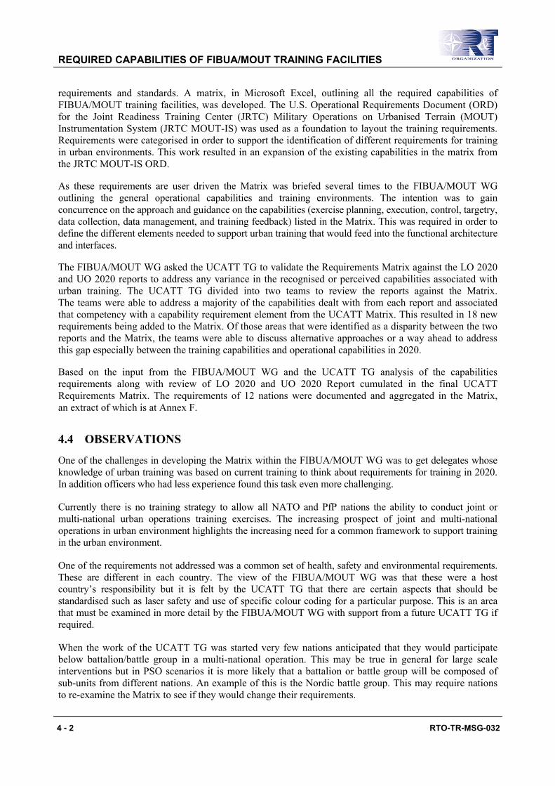
requirements and standards. A matrix, in Microsoft Excel, outlining all the required capabilities of FIBUA/MOUT training facilities, was developed. The U.S. Operational Requirements Document (ORD) for the Joint Readiness Training Center (JRTC) Military Operations on Urbanised Terrain (MOUT) Instrumentation System (JRTC MOUT-IS) was used as a foundation to layout the training requirements. Requirements were categorised in order to support the identification of different requirements for training in urban environments. This work resulted in an expansion of the existing capabilities in the matrix from the JRTC MOUT-IS ORD.
As these requirements are user driven the Matrix was briefed several times to the FIBUA/MOUT WG outlining the general operational capabilities and training environments. The intention was to gain concurrence on the approach and guidance on the capabilities (exercise planning, execution, control, targetry, data collection, data management, and training feedback) listed in the Matrix. This was required in order to define the different elements needed to support urban training that would feed into the functional architecture and interfaces.
The FIBUA/MOUT WG asked the UCATT TG to validate the Requirements Matrix against the LO 2020 and UO 2020 reports to address any variance in the recognised or perceived capabilities associated with urban training. The UCATT TG divided into two teams to review the reports against the Matrix. The teams were able to address a majority of the capabilities dealt with from each report and associated that competency with a capability requirement element from the UCATT Matrix. This resulted in 18 new requirements being added to the Matrix. Of those areas that were identified as a disparity between the two reports and the Matrix, the teams were able to discuss alternative approaches or a way ahead to address this gap especially between the training capabilities and operational capabilities in 2020.
Based on the input from the FIBUA/MOUT WG and the UCATT TG analysis of the capabilities requirements along with review of LO 2020 and UO 2020 Report cumulated in the final UCATT Requirements Matrix. The requirements of 12 nations were documented and aggregated in the Matrix, an extract of which is at Annex F.
4.4 OBSERVATIONS
One of the challenges in developing the Matrix within the FIBUA/MOUT WG was to get delegates whose knowledge of urban training was based on current training to think about requirements for training in 2020. In addition officers who had less experience found this task even more challenging.
Currently there is no training strategy to allow all NATO and PfP nations the ability to conduct joint or multi-national urban operations training exercises. The increasing prospect of joint and multi-national operations in urban environment highlights the increasing need for a common framework to support training in the urban environment.
One of the requirements not addressed was a common set of health, safety and environmental requirements. These are different in each country. The view of the FIBUA/MOUT WG was that these were a host country’s responsibility but it is felt by the UCATT TG that there are certain aspects that should be standardised such as laser safety and use of specific colour coding for a particular purpose. This is an area that must be examined in more detail by the FIBUA/MOUT WG with support from a future UCATT TG if required.
When the work of the UCATT TG was started very few nations anticipated that they would participate below battalion/battle group in a multi-national operation. This may be true in general for large scale interventions but in PSO scenarios it is more likely that a battalion or battle group will be composed of sub-units from different nations. An example of this is the Nordic battle group. This may require nations to re-examine the Matrix to see if they would change their requirements.

REQUIRED CAPABILITIES OF FIBUA/MOUT TRAINING FACILITIES
RTO-TR-MSG-032 4 - 3
The work was captured in an Excel Spreadsheet and, although this proved to a useful tool when used to capture requirements it was less useful in mapping of the functional architecture. The UK used a software application, MooD, developed to support the UK Ministry of Defence (MOD) Architectural Framework (MODAF) (similar to NATO Architectural Framework) to map the Functional Architecture to the requirements. This was demonstrated to the UCATT TG and it was recommended that it should be used to document and capture requirements and the Functional Architecture including associated information flows and data. This would also allow for future changes to be made and an expansion of the architecture as necessary.
4.5 CONCLUSION
The UCATT TG has taken the first step with the publication of the UCATT Capability Requirements Matrix which identifies the live training requirements and elements to support urban training. Although as stated it was intended to look at virtual and constructive requirements it was recognised that in the time frame that this task could not be comprehensively completed. It still needs to be done so that the requirements for the integration of LVC urban training can be documented and appropriate interoperability standards developed.
4.6 RECOMMENDATIONS
The following recommendations are made:
• The identification of an overarching approach to train within each nation’s facilities, interoperability between training systems and devices of the different countries, and supporting legacy training devices needs to be further investigated, along with the identification of the training requirements for urban operations in the areas of virtual and constructive. This should be carried out by a follow on UCATT TG.
• The relationship with the FIBUA/MOUT WG was invaluable to the work of UCATT as it provided contact with 25 NATO/PfP countries. In the event that a follow on UCATT TG is approved with a remit to examine the areas of virtual and constructive urban training requirements and LVC integration it will be necessary to establish a more formal relationship with the Army Training Group and in particular both the FIBUA/MOUT WG and TSWG. This is because they represent the user community and will need to endorse future urban training capability requirements.
• Health, Safety and Environmental requirements are examined to see if a common standard can be developed in some areas. The FIBUA/MOUT WG is currently working on Health and Safety (H&S procedures and a follow on UCATT TG should be prepared to support this work.
• Adopt the MooD software and transfer requirements data into its associated database and taking a MODAF/NATO Architectural Framework approach to future development. This will require funding support from MSCO/RTO in Paris.

REQUIRED CAPABILITIES OF FIBUA/MOUT TRAINING FACILITIES
4 - 4 RTO-TR-MSG-032

RTO-TR-MSG-032 5 - 1
Chapter 5 – FUNCTIONAL ARCHITECTURE
5.1 PURPOSE OF THE FUNCTIONAL ARCHITECTURE
The capabilities identified in Chapter 4 describe the requirements for a FIBUA/MOUT training site from a user viewpoint. In order to derive from these capabilities a generic set of requirements for the development of instrumented FIBUA/MOUT sites, it is necessary to have a common understanding of the training system from a system point of view. This means that there must be insight into the functions of the training system, how they are grouped together into components and what types of interactions take place between those components. Only then it is possible to discuss interoperability issues and compose the desired requirements.
In order to gain this insight and bridge the gap between the capabilities on the one hand and requirements for the development of instrumented FIBUA/MOUT sites on the other hand, an architecture must be created and agreed upon.
Formally, an architecture is “the organisational structure of a system or component, their relationships, and the principles and guidelines governing their design and evolution over time” (IEEE 610.12). There are many different types of architecture, but two main categories are the functional and design architectures:
• A functional architecture is “an arrangement of functions and their sub-functions and interfaces (internal and external) that defines the execution sequencing, conditions for control or data flow, and the performance requirements to satisfy the requirements baseline”.
• A design architecture is “an arrangement of design elements that provides the design solution for a product or life cycle process intended to satisfy the functional architecture and the requirements baseline” (IEEE 1220).
It is the purpose of the UCATT TG to set requirements for interoperability, which is the ability of systems to exchange data, information and services to enable them to operate effectively together. At the same time, industry should have the freedom to propose and implement the most cost-effective solutions, as long as they satisfy the interoperability requirements. So in fact, we are interested mostly in the system interfaces. In this context, an interface describes the characteristics at a common boundary or connection between systems or components.
To identify and define the system boundaries and interactions with other systems (external interfaces), it is sufficient to create and analyse a functional architecture of an instrumented FIBUA/MOUT site. This functional architecture must be representative enough to cover all of the USE CASES defined in Chapter 2 and the requirements from the capability matrix, while not touching specific design or implementation issues. The functional architecture captures what the system can do, not how it does it (e.g. by wireless transmission or through a cable).
Another subject of particular interest is the level of detail of the functional architecture. Too few details will result in insufficient possibilities for interoperability, while too many details will result in losing oversight and identifying irrelevant interfaces for interoperability.
5.2 FUNCTIONAL COMPONENTS
In practice, an instrumented FIBUA/MOUT site is composed of several sub-systems. In order to understand the system and to provide a proper context to examine the capabilities in the matrix, it helps to distinguish functional components. Within this background, a functional component is a logical sub-system of the instrumented FIBUA/MOUT site that performs a group of related functions.

FUNCTIONAL ARCHITECTURE
5 - 2 RTO-TR-MSG-032
Although functional components do have a relation with physical components or facilities, in this study it is definitely not intended to influence the physical implementation or location of the FIBUA/MOUT site. The breakdown of the system into functional components serves purely to facilitate in defining interoperability.
The UCATT TG distinguished the following 6 main functional components of a FIBUA/MOUT training system:
• Dynamic Object (DO) – This is an entity that has a status that can be changed and/or can perform activities (influencing the environment). It could be a player (e.g. a human being, a weapon system), a weapon that can be transferred to other players (e.g. a rifle), a target (e.g. a pop-up board, a dummy), a wall that can be breached, etc., a DO can be nested, e.g. a weapon can be carried by a soldier who is mounted in a vehicle.
• Exercise Control (EXCON) – The capability to define and (remotely) monitor and control an exercise. Generally this is done from a central location.
• Observer Controller (O/C) – The capability to monitor and control an exercise by distributed, local means.
• After Action Review (AAR) – The capability to analyse the results of an exercise and provide feedback to the trainees.
• System Control (SC) – The capability to monitor and control the training system itself, necessary to support the training exercise.
• Facility Control (FC) – The capability to represent the static training environment (the infrastructure, buildings, roads, etc.). This can be either fixed or mobile (e.g. containers).
The O/C component might seem a logical part of EXCON. They share a lot of functionality, but the O/C capability also has some other functionality that clearly distinguishes it from EXCON and therefore it is justified to consider the O/C as a separate component.
The following figure gives an overview of the different components. A more detailed description of all the sub-components is given in Annex G.
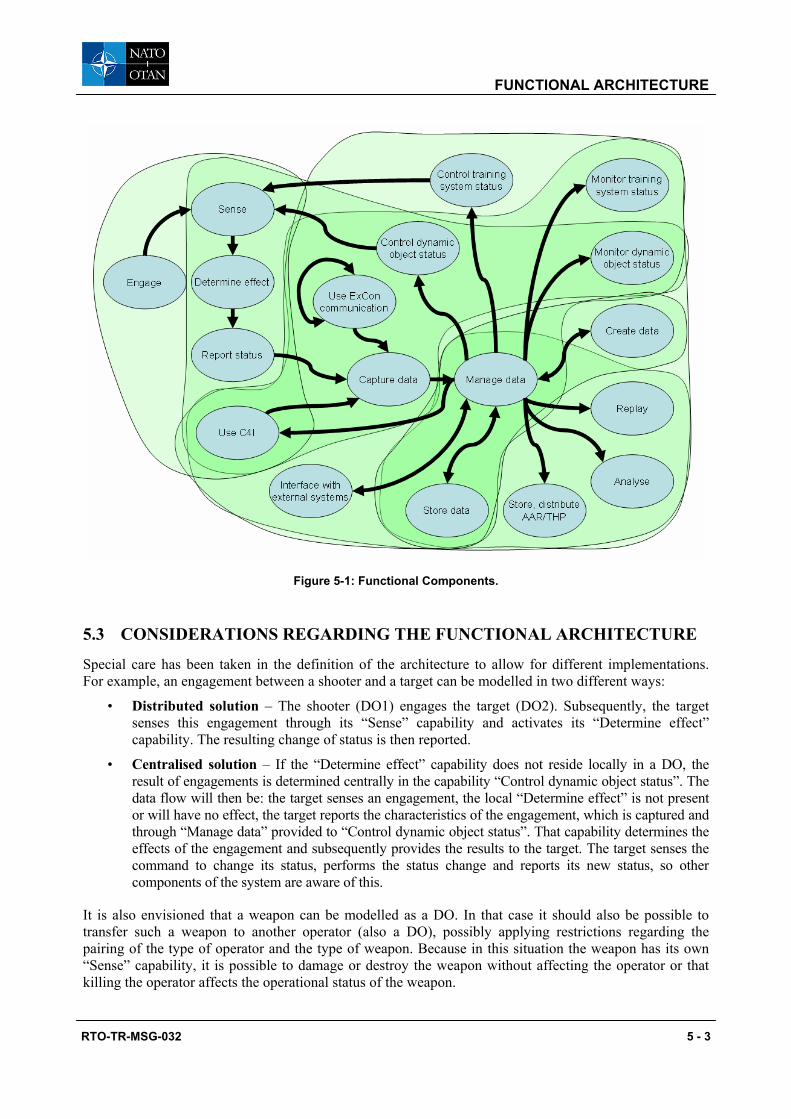
FUNCTIONAL ARCHITECTURE
RTO-TR-MSG-032 5 - 3
Figure 5-1: Functional Components.
5.3 CONSIDERATIONS REGARDING THE FUNCTIONAL ARCHITECTURE
Special care has been taken in the definition of the architecture to allow for different implementations. For example, an engagement between a shooter and a target can be modelled in two different ways:
• Distributed solution – The shooter (DO1) engages the target (DO2). Subsequently, the target senses this engagement through its “Sense” capability and activates its “Determine effect” capability. The resulting change of status is then reported.
• Centralised solution – If the “Determine effect” capability does not reside locally in a DO, the result of engagements is determined centrally in the capability “Control dynamic object status”. The data flow will then be: the target senses an engagement, the local “Determine effect” is not present or will have no effect, the target reports the characteristics of the engagement, which is captured and through “Manage data” provided to “Control dynamic object status”. That capability determines the effects of the engagement and subsequently provides the results to the target. The target senses the command to change its status, performs the status change and reports its new status, so other components of the system are aware of this.
It is also envisioned that a weapon can be modelled as a DO. In that case it should also be possible to transfer such a weapon to another operator (also a DO), possibly applying restrictions regarding the pairing of the type of operator and the type of weapon. Because in this situation the weapon has its own “Sense” capability, it is possible to damage or destroy the weapon without affecting the operator or that killing the operator affects the operational status of the weapon.

FUNCTIONAL ARCHITECTURE
5 - 4 RTO-TR-MSG-032
5.4 INTERNAL AND EXTERNAL INTERFACES
In the context of our functional architecture, an interface is a connection between system functions over which data is exchanged. Those interfaces must be identified and the type of data which is transferred over those interfaces must be specified, as part of the guidelines for interoperability. Annex H describes in more detail the internal and external interfaces.
A distinction can be made between internal interfaces and external interfaces. An external interface is a possible connection between two different systems, while an internal interface is never involved in transferring data between different systems. For the purposes of interoperability, and thus for the objectives of the UCATT, internal interfaces are not of interest and do not have to be specified any further.
Considering every interface as an external interface would yield the greatest flexibility regarding interoperability: communication can be established irrespective of the system to which the involved system functions belong. However, this solution would also pose the most restrictive demands on the design of FIBUA/MOUT sites.
As stated before, the starting point of this study is the USE CASES and those determine the external interfaces. For example, it cannot be deduced from the USE CASES that a sensor from a DO should be replaced by a sensor from another system. Instead, the DO as a whole is seen as the indivisible entity that interoperates with other systems. Therefore the interface between the system functions “Sense” and “Determine effect” is considered as an internal interface.
Another decision to limit the number of external interfaces is to assume that once data has arrived within a system, it will be managed by the system’s central function “Manage data”. That function will provide other functions access to the data they require through internal interfaces.
Data will arrive within a system through the functions “Capture data” and “Interface with external systems”. “Capture data” is a function that receives real-time data from a DO and C4I systems. The function “Interface with external systems” was created to exchange data between systems real-time and off-line. For example, it must be possible to execute an exercise in System A and analyse the recorded data in System B. Instead of declaring the interface between “Manage data” and “Analyse” as an external interface, the recorded data will be sent to System B, using “Interface with external systems”, whereupon System B will provide its relevant functions access to that data.
Based on the analysis of the USE CASES, the following external interfaces, as illustrated in Figure 5-2 were identified.

FUNCTIONAL ARCHITECTURE
RTO-TR-MSG-032 5 - 5
Figure 5-2: External Interfaces (E1 to E8).
5.4.1 Engage ⇒ Sense (E1) (⇒ is the direction that data flows)
This interface is the interaction between dynamic objects and implements for example the direct fire from a shooter (DO1 from System A) on a target (DO2 from System B).
5.4.2 Control Training System Status ⇒ Sense (E2)
This interface controls the technical status of a dynamic object. Through this interface it is possible that system control from System A starts up or calibrates DO2 from System B.
5.4.3 Control Dynamic Object Status ⇒ Sense (E3)
This interface controls the operational status of a dynamic object. An example is that EXCON from System A assigns a kill to DO2 of System B, either as a direct action or to simulate the effects from an artillery strike.
5.4.4 Report Status ⇒ Capture Data (E4)
The status of DOs is communicated through this interface. It includes for example DO2 of System B signalling it being damaged to EXCON of System A.

FUNCTIONAL ARCHITECTURE
5 - 6 RTO-TR-MSG-032
5.4.5 Use EXCON Communication ⇔ Use EXCON Communication (E5) (⇔ implies a two way flow of data)
This interface enables the communication between training staff members of different systems operating in the same exercise. For example, an O/C wearing equipment from System B must be able to communicate with the O/C and training staff in EXCON of System A.
The interface between “Use EXCON communication” and “Capture data” is not considered as an external interface. The reason for this is that since the EXCON communication capability is already interoperable, each system can capture the training staff communication using its own mechanisms.
5.4.6 Use C4I ⇒ Capture Data (E6) When military personnel are equipped with C4I systems, it is assumed that the training staff are also equipped with those C4I systems, to monitor the situational awareness of the troops or to provide input to those C4I systems (for example to represent a higher control headquarters).
This interface provides data from C4I systems to the FIBUA/MOUT site. This includes for example a report from a scout that he has detected an enemy vehicle or a graphical sketch showing the situation. This data can be stored in the training system for analyses purposes and can be used during AAR.
It is recommendable that different C4I systems should be interoperable among themselves, but that is considered outside the scope of this study and within NATO it is the responsibility of NC3A.
5.4.7 Manage Data ⇒ Use C4I (E7) This interface provides data from a training system to a C4I system.
An operational overlay created by the training staff and used in EXCON can be distributed to the C4I systems of the troops that are training. It could also be possible that the training system provides status information of entities (either “live” dynamic objects or “virtual” players) to the C4I systems.
5.4.8 Manage Data ⇔ Interface with External Systems (E8) This interface enables the exchange of data between training systems. This interface can be either off-line or real-time. Examples of off-line data exchange are the transfer of a created scenario from System A to System B and the transfer of a recorded exercise from System A to System B. An example of a real-time data exchange is the creation of a minefield in System A, which is communicated to System B.
5.5 CONCLUSION
Based on the USE CASES and the capability requirements matrix the UCATT TG defined a functional architecture, which provides the context to define requirements for interoperability. The functional architecture reflects the capabilities that a FIBUA/MOUT site must possess, finding a balance between applicability and complexity, without addressing implementation issues. Since the purpose of the UCATT TG is to set requirements for interoperability, it is recommended that the external interfaces defined in this chapter have to be standardised. This is the subject of Chapters 6 and 7.

RTO-TR-MSG-032 6 - 1
Chapter 6 – DATA INTEROPERABILITY ANALYSIS
6.1 PURPOSE
The purpose of the data interoperability analysis is to identify those components of the overall training system (based on the Functional Architecture, Chapter 5) that have external interfaces and therefore require standardisation if multi-national training is to be supported by future MOUT sites. The data interoperability analysis does not include specific recommendations regarding the structure of data or the method of transmission, but it does detail the content of data transmissions.
6.2 APPROACH
6.2.1 Focus of Analysis
Dynamic Objects (DO) (participants, weapons and platforms) were the primary focus of this analysis since these are the elements of the system that are likely to travel to another location for training purposes (see the USE CASES in Chapter 2). The training buildings, in some cases also dynamic objects, must also be able to react to attacks from visiting troops and the analysis therefore examined these external interfaces as well.
This analysis focuses on the interactions of DOs. The external interfaces are E1 (between DOs) and E4 (from DO to EXCON), as identified in Chapter 5. The UCATT TG described the categories of data being transferred between functional components, distinguishing between trigger events, outgoing events and effects. This analysis takes into consideration all conceivable weapon types (direct fire, area weapon, chemical attacks, and so on), platforms and infrastructure, to ensure that interoperability can be defined for multi-national exercises. This analysis is presented in Annex I.
The data interoperability analysis is presented as a tabular account of what takes place from the time a weapon is fired until an engagement report is available at the EXCON. This sequence is populated with some exemplar interactions for major weapon and target types.
6.2.2 Assumptions
The main assumption is that before any country can be interoperable internationally, it must be internally interoperable: each country should have the capability to operate instrumented combined arms exercises. To enable interoperability, this core capability is then subject to the external interfaces identified in Chapter 5. If any of these core features exist for one country and not the other, then interoperability will only be possible at the lowest common feature set. However, if both countries populate the feature set, then interoperability is feasible, even if the actual mechanisms differ between countries.
To help define these feature sets, the UCATT WG has described the case of a DO vs. DO engagement. Annex I shows how the sequence of events moves from the initial trigger pull or detonation through to reporting to EXCON and any secondary effects. The information within these events is provided as a complete feature set which can include non-transmitted information. This is important as certain assumptions about the data are made in the process of physically implementing a system.
Take the example of a DO to DO engagement event: the sequence of shooting to engagement report can be achieved using two methods:
• Local engagement adjudication; and
• Remote/centralised engagement adjudication.
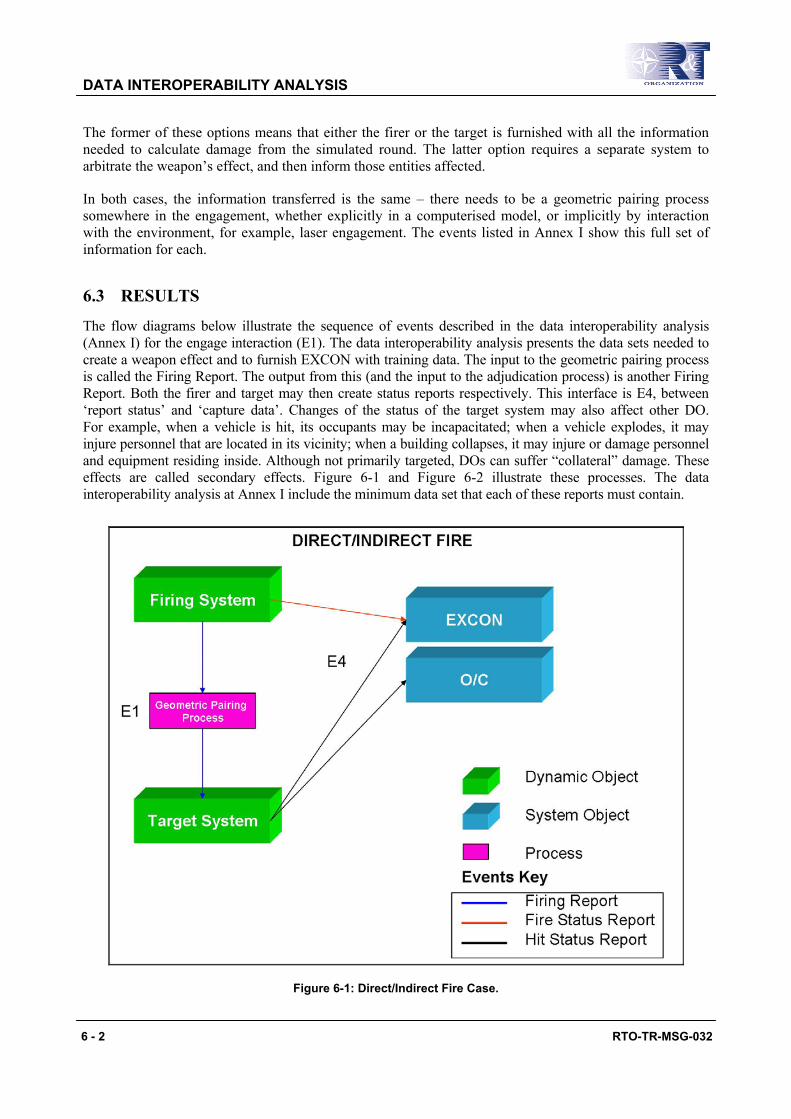
DATA INTEROPERABILITY ANALYSIS
6 - 2 RTO-TR-MSG-032
The former of these options means that either the firer or the target is furnished with all the information needed to calculate damage from the simulated round. The latter option requires a separate system to arbitrate the weapon’s effect, and then inform those entities affected.
In both cases, the information transferred is the same – there needs to be a geometric pairing process somewhere in the engagement, whether explicitly in a computerised model, or implicitly by interaction with the environment, for example, laser engagement. The events listed in Annex I show this full set of information for each.
6.3 RESULTS
The flow diagrams below illustrate the sequence of events described in the data interoperability analysis (Annex I) for the engage interaction (E1). The data interoperability analysis presents the data sets needed to create a weapon effect and to furnish EXCON with training data. The input to the geometric pairing process is called the Firing Report. The output from this (and the input to the adjudication process) is another Firing Report. Both the firer and target may then create status reports respectively. This interface is E4, between ‘report status’ and ‘capture data’. Changes of the status of the target system may also affect other DO. For example, when a vehicle is hit, its occupants may be incapacitated; when a vehicle explodes, it may injure personnel that are located in its vicinity; when a building collapses, it may injure or damage personnel and equipment residing inside. Although not primarily targeted, DOs can suffer “collateral” damage. These effects are called secondary effects. Figure 6-1 and Figure 6-2 illustrate these processes. The data interoperability analysis at Annex I include the minimum data set that each of these reports must contain.
Figure 6-1: Direct/Indirect Fire Case.

DATA INTEROPERABILITY ANALYSIS
RTO-TR-MSG-032 6 - 3
Figure 6-2: Secondary Effects.
6.4 FURTHER WORK
6.4.1 Training Environment Standardisation There is more to training interoperability than just the system interoperability described in Chapter 5. The need for common training procedures is known in as much as when a visiting unit is briefed at a foreign training facility, they are told the local ‘rules’, both for safety and integration with other national forces. The UCATT TG has identified interoperability areas that result in the need for hardware standards, but are actually driven by training methodology. An example is the indication of battle damage to vehicles: Swiss forces use orange smoke to indicate a kill, whereas in the UK, a flashing white strobe light is used. The UCATT sister group, the FIBUA/MOUT WG, will be advised on training interoperability areas that need a military resolution. However, where a generic response is required from the technical system, the UCATT TG will provide advice. For example, indication of a round’s effect on a target will usually require some kind of visual response, whether it is smoke, light or other pyrotechnic device. Annex J, Appendix J2 shows examples of effects that might be required for each event.
There is a need for continued development of internationally recognised training standards. The UCATT TG has compiled a table of effects expected to be encountered. These encompass audio and visual effects – final ratification of these effects will be provided by further development of international training standards.
There is a need for a set of vulnerability tables that can be used by different countries, whilst maintaining each country’s proprietary capability data. This could either be a generic data set, or an agreed simplified set of data provided by each country or vehicle provider.
DATA INTEROPERABILITY ANALYSIS
6 - 4 RTO-TR-MSG-032
6.4.2 Health and Safety As well as training coherence issues, H&S must be addressed. For example, laser training in the United States uses Class 3a, whilst in the UK eye-safe is considered as Class 1. This safety issue would prohibit the use of US training equipment against UK troops, regardless of technical interoperability.
H&S issues would fall into three categories:
• Training procedures and reporting;
• Physical impact of training equipment; and
• Radiation impact of training equipment.
The FIBUA/MOUT WG is currently working on H&S procedures and standards for urban training.
The physical impact of training equipment needs to be standardised across countries – this might take the form of existing military or civilian safety standards (e.g. MILSTD, BS Kite Mark). These standards can be reviewed to assess if a suitable lowest common safety standard can be implemented.
Safe levels of radiation from radio antennas and laser emitters, is an area that is being researched. As most military RF systems are based on civilian systems (e.g. microwave, cellular phones) any safety standards should leverage off these developments.
6.4.3 Other External Interfaces The focus on dynamic object interfaces E1 and E4 provides an immediate way forward for inter-entity level interoperability. The next chapter sets out a standard coding for the E1 interaction. However, to fully develop the dynamic object interoperability, E4 must also be considered.
There is still a requirement for the other external interfaces, described in Chapter 5, to be explored. However, not all these capabilities are extant in most country’s training systems, particularly for integration with C4I systems. Further work to define these interactions is needed before a complete standard can be produced. In some cases, operational interoperability standards may be re-useable within a training system. The decision by the U.S. Army in September 2005 to use the Command and Control Information Exchange Data Model (C2IEDM) (now replaced by the Joint Consultation, Command and Control Information Exchange Data Model (JC3IEDM)) as the interface between Modeling and Simulation (M&S) systems and C4I system, and the fact that JC3IEDM is being developed by 26 nations under the Multi-national Interoperability Program (MIP) would be the logical starting point in conducting further analysis.

RTO-TR-MSG-032 7 - 1
Chapter 7 – INTEROPERABILITY CODE SETS
7.1 OBJECTIVE This chapter, as the rest of this report, is dedicated to the growing need for multi-national military training in urban environments. The UCATT TG proposes a methodology to achieve a standard for live (force-on-force) urban combat engagement codes (referred to as the UCATT Code). In order to approach this goal the group has undertaken all the research and discussions depicted in the previous chapters. The architecture as described in Chapter 5 and expanded in Chapter 6 provided the External Interfaces that were required to be interoperable (E1-E4). This was done to gain an understanding of the military training needs of all participating nations. This chapter focuses on the External Interface E1.
The approach to this subject has been governed by the needs and capabilities of the future. Future technology and capabilities have been predicted by the UCATT TG, using a conservative approach. These capabilities need to be included into the design of the future engagement standard. This must be done to create a powerful innovative standard that shall be capable of handling future needs rather than trying to accommodate worldwide existing standards (legacy standards) and downsizing future requirements to old or existing capabilities. However legacy systems are a fact and any standard proposed that does not consider these existing systems will be destined to exist as a perfect technical solution that will never be used in the real world. Therefore this chapter proposes mechanisms that will guarantee the migration from existing systems to a future standard.
Upon closer investigation it became clear to the UCATT TG that engagements need to be standardised not only in the mere process of the actual engagement but in all aspects of its manifestation in the training environment. The UCATT TG identified the following engagement aspects that need to be standardised:
• The actual engagement – the simulation of a weapon firing event and the transaction between shooter and target;
• The vulnerability (model) of the target – the definition of a target’s susceptibility to a given threat type;
• The effect representation – the characterisation of the multi-sensory (e.g. acoustic, optical) response to an engagement; and
• The data communication aspect of the engagement – the process of sharing information through technological media.
The scope of these issues is beyond the capacity of the group at this time. A future UCATT TG should continue to investigate and pursue the implementation of the issues outlined in this chapter. As an example of the process the following sections attempt to outline the elements of standardisation of the first three bulleted points above.
7.2 STANDARDS TO SUPPORT URBAN TRAINING IN 2020 The need to conduct a range of different urban training scenarios by 2020 was outlined in Chapters 1, 2 and 4 and the UCATT capability requirement matrix (Annex F). Those requirements will dictate the level of fidelity that goes into this standardisation process.
The weapon systems of the near future will have greater range, better effects and an increased Non-Line of Sight capability (NLOS). “Fire and Forget”, “Less Than Lethal” weapons and “Cooperative Engagement” capabilities will have more impact on the training environment. A list of the weapon systems currently used in the military FIBUA/MOUT training community was initiated by the FIBUA/MOUT WG and can be found in the Appendix J1.

INTEROPERABILITY CODE SETS
7 - 2 RTO-TR-MSG-032
The current simulators are mostly capable of supporting line of sight interaction. The capabilities needed for the future NLOS are presently under development and will potentially be fielded in the near future. A future standard needs to implement all principles and methods to negotiate between the possible implementations.
7.3 LEGACY SYSTEMS AND TRANSITION
Many countries have already procured force-on-force simulation equipment of various kinds. Some other countries are presently procuring equipment or CTC systems. Some examples of existing codes can be found below (and there might be systems currently under development with proprietary code sets that will have to be considered up until the year 2020 and potentially beyond):
• MILES I/II
• AMSTI-90 ‘MILES’
• OSAG (Optical System Interface for AGDUS and the German CTC)
• COSIM
• TALISSI
• SIMLAS
• REACT
• ENCL, NCL, ACL
• SIM FIRE
• FAST-CODE
This list is only included to give the reader an insight into the diversity of present systems. It does not try to evaluate the capabilities of the depicted main suppliers. Some of the codes are proprietary to the main supplier, other codes are public domain and some codes are government confidential.
Since legacy systems are a fact in the real world and it is highly unlikely that a government will decide to discard their investment in current simulation equipment, an orderly transition solution from legacy, to “UCATT code” systems would be optimal. This transition is described in more detail in Section 7.8 and illustrates proven methods and procedures to obtain a transitional capability that allows the continued usage of the legacy systems while the UCATT code capable systems are gradually implemented.
7.4 ENGAGEMENT ASPECTS
This section deals with the functions of the Functional Components as outlined in the previous chapters. It identifies the different data sets needed to engage a target:
• Engagement data set (see Section 7.4.1); and
• Vulnerability data set (see Section 7.4.2).
7.4.1 Engagement Data Set (TES-Code) The UCATT code has to be open source covering the information needs of modern simulation training. It needs to be free of company intellectual property rights (IPR), provided under Open Content License and standardized (see Section 7.10.1).

INTEROPERABILITY CODE SETS
RTO-TR-MSG-032 7 - 3
7.4.1.1 Dual Structure of the Code Sets
The UCATT TG has identified the following parameters for the external interface E1 as defined in the External Interface information sets (Annex I) and illustrated in Table 7-1 below.
Table 7-1: External Interface Information Set
Object Report Types Must Know Data Inherent in Must Know Data Firing Report Shooter Platform ID Type (vehicle, person, aircraft)
Call-sign
Affiliation (red force, blue force, civilian, etc.)
Assignment (leader squad 1, supply vehicle, etc.) Shooter Platform Location X position
Y position
Z position Weapon ID Weapon Type Ammunition Ammunition Type
Type of delivery (direct, indirect)
Type of effect (explosive, smoke, biological, etc.)
Duration of effect (immediate, temporary, lingering, etc.)
Aim point Location
Orientation
Angle
Charge
External conditions (wind, etc.)
Weapon conditions (barrel temperature, etc.) Type of detonation Impact
Proximity
Time
This comprehensive approach to the engagement procedure (transmitting all data that might be required by non-target designating systems) leads to:
• The creation of a large engagement data set (namely all data required to specify the lethal envelope); and
• The need to transfer the larger engagement data set to every DO in the field.
Every single engagement therefore results in a large number of transmissions or information “broadcast” to all DO while only one or eventually a few DOs need to receive the data.

INTEROPERABILITY CODE SETS
7 - 4 RTO-TR-MSG-032
On the other hand only a small sub-set of this data is required and sent to only one (or a few) DO if the attacker has the ability to designate an individual target and already determine the point of impact on the target as it is standard with sophisticated TES systems (2nd generation precision systems).
It is therefore desired to create a code set that can serve both situations depending on the target designating capability of the attacking DO.
If possible it is recommended to compress the transmitted data using a non-mutating compression algorithm. It might actually be desirable to use an error correcting code to prevent code re-transmissions.
7.4.1.2 Data Encoding Needs
The UCATT TG found that the number of DOs (e.g. Players) will increase as a result of the proposed concept. The UO2020 report [4] also indicates that the number of weapon systems and ammunitions used will increase in the future.
Summing up the expected code needs for 2020 we can safely assume that the code will have to accommodate large numbers (the UCATT TG definition of DO mandates a player number for any active portion of a building such as windows, doors, walls, roofs, rooms, etc.). Therefore the proposed data structure needs to include an extensive number of possible DO of various types (as described in Section 5.2). The structure needs to provide a large number of weapons and ammunitions that should be sufficient to last well past the year 2020. The accuracy of the engagement itself (hit position values) needs to be increased in order to satisfy the needs of 2020.
7.4.1.3 Target Designating Engagements
Systems that are able to designate targets during the engagement process are able to operate with a smaller set of the UCATT code. Designating engagement parameters may therefore be transmitted using a sub-set of the UCATT code. This sub-set will also be used for other DO (e.g. O/C) if applicable.
Table 7-2: Data Set Required for Target Designating Engagements
Object Report Types Must Know Data Inherent in Must Know Data
Firing Report Platform ID Unique player code
Weapon ID Weapon Type
Ammunition Ammunition Type (determines: effect, duration, …)
Hit Position X,Y coordinate of the impact
Flight Time Time till impact
Hit Distance Proximity of the target
7.4.1.4 Possible Code Set for Target Designating Systems
The described UCATT target designating code sub-set is designed in a way to mature during the time of usage by using a fixed system of code population (see Appendix J2 for details). This creates an ability to adapt to the technological advancements that are expected during the life-time of the code without the need to change the code itself.
7.4.1.4.1 Capabilities of the UCATT Target Designation Code Sub-Set
The capabilities are:

INTEROPERABILITY CODE SETS
RTO-TR-MSG-032 7 - 5
• More than 42 million DO – Players (42,515,279).
• More than 500 thousand different weapon systems (524,879).
• More than 6000 different ammunitions per weapon system (6480).
• Target accuracy from 1 mm up to 500 m.
• Distance from 0 m up to 500,000 m.
7.4.1.4.2 Structure
The structure of the UCATT target designation code sub-set is targeted towards TES interoperability. The described structure can currently be implemented within the limits of eye safety if used for laser simulation and should pose no difficulty in future implementations. The UCATT code structure as described is intended to operate in a manner that enables a single data word to transfer all necessary data to complete an engagement. One data word includes a complete shot result or a complete control/test instruction respectively. The information is not divided into several data words. Each data word comprises 24 elements each. Each element offers 80 possible data positions. For safe detection each data word is transmitted four times.
Bottom Up definition:
• 80 bits form one element.
• 24 elements form one word.
• One word is one data set.
7.4.1.4.3 Data Word Contents
The elements of each data word are defined as follows:
• Elements 1 and 2: Sync
The first pulse positions in Elements 1 and 2 are always occupied, resulting in a pulse distance of 40 µs.
• Element 3 to 5: Weapon ID Code
The weapon type of the attacking dynamic object is encoded in Elements 3 to 5, thus offering a range of 524,879 individual weapon types.
• Elements 6 and 7: Ammunition Code
In these elements the ammunition type is encoded. This element has to be evaluated in combination with Elements 3 to 5, offering 6480 different ammunition types per weapon. An example of this element would be:
5 calibre 7.62 standard
6 calibre 7.62 tracer
7 calibre 7.62 full metal
8 …
The Elements 3 to 7 are providing enough code capability for 524,879 weapons with 6480 ammunition types per weapon.

INTEROPERABILITY CODE SETS
7 - 6 RTO-TR-MSG-032
• Elements 8 to 12 and 14: Hit Position Code (azimuth: x and elevation: y)
These elements describe the deviation of hit position in azimuth and elevation as measured by the attacking system in relation to the centre of the target. The value range is from 1 mm up to more than 500 m.
This element ensures that even a 500 m miss can still be transferred to the target.
• Elements 16 to 18: Hit Distance
The hit distance is the sum of the values given in Elements 16 to 18 in meters. This value ranges from 0 m all the way to 505,600 m.
The Element 18 codes 18-79 and 18-80 are used to transmit alternate code selection information to the other system to enhance the code scheme even more (providing two possible sub-sets of the code).
• Elements 19 to 22: Platform ID Code
The Player ID (PID) number of the attacking simulator is encoded in Element 19 to 22, thus offering a range of more than 41 million possible players.
• Element 23: Flight Time Code
The flight time of any ammunition can be coded into Element 23 offering a flight time in seconds up to 80 sec.
• Element 24: Checksum
The checksum is derived summing up the Elements 3 to 23, modulo 80. It is used to determine the validity of any received code.
• Elements 13, 15: Reserved
The code provides 2 reserved elements that can be used to implement special codes and other elements needed in the future.
7.4.1.4.5 Timing for Time Based Coding Systems (e.g. Laser Simulation)
For time based coding systems the following timing can be used to ensure a data transmission that covers the needs of 2020 scenarios. The values described below are within the technological capacity of present systems. The timing, if applied with laser simulators, can currently be implemented within the limits of eye safety and should pose no difficulty in future implementations:
• Each Pulse Interval (PI) has a length of 500 ns.
• Each element (80 PI) has a duration of 40 µs.
• 24 elements form one word with a duration of 960 µs.
• Each word is repeated 4 times with a spacing of 1 ms.
• A complete time based transmission therefore requires about 7 ms.
• Short transmission time to ensure code transmission without restrictions on weapon handling.
The timing is depicted in the Graph 7-1 below.

INTEROPERABILITY CODE SETS
RTO-TR-MSG-032 7 - 7
8079787776757473...n...87654321
Each Element comprises 80 Pulse Positions of 500 ns each (40 us)
2423222120191817...e...87654321
24 Elements of 40 us each (960 us)
8079787776757473...n...87654321
Each Element comprises 80 Pulse Positions of 500 ns each (40 us)
2423222120191817...e...87654321
24 Elements of 40 us each (960 us)
8079787776757473...n...87654321
Each Element comprises 80 Pulse Positions of 500 ns each (40 us)
2423222120191817...e...87654321
24 Elements of 40 us each (960 us)
Graph 7-1: Overview of Timing.
In each element up to one data position may be occupied. The first pulse positions in Elements 1 and 2 are always occupied, resulting in a pulse distance of 40 µs.
In all elements exactly one pulse position has to be occupied. This results in 22 elements which are used for information encoding. Together with the two synchronization pulses mentioned before, each data word comprises exactly 24 pulses.
Information on which pulse position is occupied is defined by the leading edge of the pulse, while the pulse itself as a rule is significantly longer than one pulse position.
7.4.1.5 Non-Target Designating Engagements Target designating engagements between a shooter and a target are defined as interactions where the involved DOs can directly exchange information. Examples are a soldier firing his rifle at another soldier or a tank firing at a building.
Non-target designating engagements are interactions between a weapon system (ammunition) and other DOs where the other DOs can only be determined during activation of the weapon. Often this applies to Area Weapon Effects, indirect weapons or guided munitions. Examples are the explosion of an artillery shell, a hand grenade or a chemical cloud. Information for non-target designating systems (e.g. hand grenades that have area weapon effects) may include the data described in Table 7-1.
Non-designating engagement parameters may be transmitted using the entire UCATT code. This code will be used for other DO if applicable. The UCATT TG has identified the need for an extended non-target designating code portion. A future UCATT TG needs to pursue a compatible, non-target designating code addition. This addition would determine how to send TES data for non-target designating weapon systems. The UCATT TG did not complete this portion of the code definition but it is recommended that this is addressed in the near future.
7.5 VULNERABILITY DATA SET This section deals with the necessity to have standardised vulnerabilities if multi-system (synonym for multi-national) exercises shall be conducted. Interoperability is not only achieved by the ability to engage the other system. Similar engagements (e.g. the same calibre on the same type of vehicle) need to cause similar damage.
Vulnerability is included in the force-on-force simulation world by a representation of the objects vulnerability parameters (commonly known as vulnerability models). Vulnerability and engagement
INTEROPERABILITY CODE SETS
7 - 8 RTO-TR-MSG-032
parameters are assessed to determine the outcome of any engagement. It is therefore obvious that vulnerability and engagement parameters need to be of one kind (one code) in order to get appropriate results. The restriction is actually even harder in such a way that a given code set does not define the outcome of the engagement since the vulnerability model finally defines the object’s post engagement status. Only a matched code set plus matched vulnerability models ensure the desired object interaction.
The UCATT TG proposes to develop standardised training vulnerability models that can be used instead of “classified” national vulnerability models during joint exercises. The overall architecture will also need to support the use of classified models in individual countries’ indigenous exercises.
7.6 EFFECT REPRESENTATION (ER) DATA SET
This section deals with the necessity to use similar or identical means of effect representation (ER) for defined engagement results (acoustical, visual, etc.). The ER feedback has to be aligned under multi-national training conditions in order to guarantee identical action and behavior on the recipient side of the ER process (e.g. soldiers will expect identical visualization of a certain weapon effect).
This section acknowledges the need for ER but the final decision should be agreed upon by the NATO FIBUA/MOUT WG and TSWG since they represent the user community and have the relevant military experience to evaluate possible solutions. The tables in Appendix J3 are intentionally provided in order to initiate the thought process. The UCATT TG expects changes to this table to be completed by the military subject matter experts. The content was provided by populating the tables at Appendices I1 and I2 (Fire and Target Entity Events) that supported the data interoperability analysis in Chapter 6.
There is no need to standardise “system internal” ER (e.g. messages displayed inside a vehicle). These representations do not influence the behavior of other players and – if well designed – do not lead to misinterpretation of certain engagement situations. It is up to the respective nation/system manufacturer to implement appropriate “system internal” ER.
7.7 DATA COMMUNICATION ASPECTS OF THE ENGAGEMENT
The UCATT TG has identified the need for a standardised data communication protocol on the level of the DO external interfaces. A future UCATT TG needs to pursue a common data communication interface in order to address the need for a common data communication. The standard determines how to receive and evaluate incoming data. The UCATT TG refrains from a definition of the final physical layer that eventually transports the data. This exceeded the current capabilities of the group and needs to be addressed in the near future.
7.8 TRANSITION PHASE
7.8.1 Background The procedures and technologies proposed in this chapter have been implemented and used successfully on various projects already. They are designed to provide the ability to transition from a multi-code to a standardised universal code. The depicted solution ensures a safe and gradual transition from the old code set to the new set while maintaining the usual training capabilities.
Looking at Section 7.4.2 it might sound contradictory to state that the key to interoperability is actually the capability to use or provide better support to several vulnerability models. Upon closer examination however the first paragraph mandates only matched vulnerability models but does not exclude additional

INTEROPERABILITY CODE SETS
RTO-TR-MSG-032 7 - 9
models. As long as the models are clearly distinguished (e.g. by code) it is possible to match attacker parameters with the corresponding vulnerability model.
The general concept is to support the transition phase by allowing two or more code sets (legacy1, legacy2 and the UCATT code set) to be used in parallel. A code discriminator will identify the received code and provide it to the “responsible central interface”. This would be done by first selecting the vulnerability model (e.g. by the attacker’s code) and secondly by applying this attacker code to the chosen (matching) vulnerability model.
This concept has the advantage that it is not bound to a certain means of data transmission (e.g. laser) but offers the ability of being interoperable with different TES implementations. It is a proven technological standard and it can be implemented in a cost efficient way during the normal upgrade cycles of the systems.
7.8.2 General Concept The main idea is to support the transition phase by allowing two or multiple code sets to be received. A code discriminator will identify the received code and provide it to the “responsible central interface”. This is illustrated in Figure 7-1.
Legacy Vulnerability Table
UCATT Vulnerability TableMulti-Code
Receiver
Code Discriminator
Figure 7-1: General Concept.
The general transition concept might require additional hardware for the legacy systems but this additional hardware can still be used after the transition. If the legacy receivers can be programmed to accept the UCATT code it might be possible to initiate the transition by upgrading the decoding software.
7.8.3 Definitions The following definitions are given for the sake of clarity and are not intended as hardware design guidelines. Functions may be manifested in one or several pieces of hardware. The definitions are based on a hardware concept that is typical for present TES systems, but as said before the design is not mandatory:
• Multi-Code Receiver: A receiver that is able to receive the legacy code as well as the UCATT code. This receiver will be typical to the legacy code; it might be a universal (multi-legacy code capable) version.
• Code Discriminator/Translator (CDT): The CDT decodes the received data and decides which central interface is responsible for the received code. It can also translate received codes into another legacy code scheme. Translation is always limited to the capabilities of the legacy code (the UCATT code is stronger than legacy codes; it cannot fully be translated into legacy code).

INTEROPERABILITY CODE SETS
7 - 10 RTO-TR-MSG-032
• Central Interface (CI): The CI stores the vulnerability tables and reports engagement results according to the legacy or UCATT code requirements.
7.8.4 Legacy System Engaging UCATT System
7.8.4.1 Legacy System Engaging UCATT System with Legacy CI on Target
Legacy System UCATT System
Legacy CI Report
UCATT CI Unused during transition
CDT
Figure 7-2: Legacy -> UCATT (Legacy CI).
If a legacy system engages a UCATT system the CDT will identify the legacy code and send the code to the legacy CI. This might be necessary during an early stage of the transition that is governed by a large number of existing legacy systems. The UCATT CI would be part of the UCATT system but not yet activated in this early stage of the transition.
7.8.4.2 Legacy System Engaging a UCATT System
Legacy System UCATT System
UCATT CI Report
Code translation
CDT
Figure 7-3: Legacy -> UCATT.
If fewer legacy systems exist it will be possible to activate the UCATT CI on the target systems and use the extended functionality of the UCATT code. If a legacy system engages a UCATT system the CDT will identify and translate the legacy code into the UCATT code and send the code to the UCATT CI.

INTEROPERABILITY CODE SETS
RTO-TR-MSG-032 7 - 11
7.8.5 UCATT System Engaging Legacy System
7.8.5.1 UCATT System Engaging Legacy System with UCATT CI on Target
UCATT System Legacy System
UCATT CI CDT
Report
Legacy CI Unused during transition
Figure 7-4: UCATT -> Legacy (with UCATT CI).
If a UCATT system engages a legacy system the CDT will identify the UCATT code and send the code to the UCATT CI. This solution ensures that all UCATT code features can be used at an early stage of the transition process. However it requires an additional UCATT CI on all involved legacy systems.
7.8.5.2 UCATT System Engaging Legacy System with Legacy CI on Target
UCATT System Legacy System
Legacy CI Report
CDT
Code translation
Figure 7-5: UCATT -> Legacy.
If a UCATT system engages a legacy system the CDT will identify and translate the UCATT Code into the legacy code and send the code to the legacy CI. This is done during a transition phase to ensure operation of existing equipment. This solution requires the need to solve over-capacity problems (e.g. avoid large PID numbers possible in the UCATT code) in the training organization structure.
7.9 OSAG CODE TRANSITION PHASE SUPPORT CONCEPT
The UCATT TG proposes to finish the code transition phase by the year 2020 which is 13 years after the publication of this report. Appendix J4 depicts how the OSAG code can be modified to achieve a level of interoperation that would enable the OSAG code community to conduct joint training operations in the near future, in effect at the beginning of the 13 year transition phase.

INTEROPERABILITY CODE SETS
7 - 12 RTO-TR-MSG-032
Appendix J4 shows in detail how to modify existing OSAG systems to support the increase in number of weapon systems already used. This next section is an extract from that appendix. The total number of possible ammunition codes is increased by the factor 2.5. The total number of weapon systems classes is raised to 38 classes using 2 to 10 different ammunition types. During international exercises all codes will be interpreted as the generic ammunition type of the applicable class.
7.9.1 Guiding Principles The following are guiding principles on how to achieve a code system that has a defined ammunition code structure and which allows unique user defined ammunitions to be implemented. A brief description would be to say that the OSAG II proposal is an introduction of 38 ammunition classes (categories) which are described in Appendix J4. Every single one of these classes is defined by a generic ammunition code and the first ammunition code within the sequence of codes belonging to the applicable class is to be implemented and interpreted in the same way in every system supporting this new approach.
Each user nation can then choose and define unique ammunitions within the appropriate class, based on ammunition effect, using the remaining ammunition codes. These codes can be used during national exercises. During joint training the 38 ammunition classes will be used to determine the effects of an engagement. The more precise, user nation specific ammunitions can be used during national (single user) training, enhancing the training fidelity by providing detailed information about the particular ammunition. During national training exercises the proposed concept ensures that all simulators will still be able to interpret the ammunition codes according to the locally defined tailoring with the unique ammunition code implementations that exist today. During international exercises, the proposal eliminates the problem with undefined codes as all codes, unless identically defined, will be interpreted as the generic ammunition type of the applicable class. As an example all rocket propelled grenade type weapons (Carl Gustav, Panzerfaust, Bazooka, RPG7, etc.) are interpreted as the same generic weapon (AT Rocket).
7.10 WAY AHEAD
7.10.1 SISO Standardisation SISO is an organisation supporting standards development. SISO is well established in the military simulation community, and has several yearly conferences focusing on interoperability. SISO has among its record of products the Distributed Interactive Simulation (DIS) and the High Level Architecture (HLA). Both DIS and HLA standards are cornerstones of interoperability in all types of simulation today.
The UCATT TG proposes the identified engagement aspects to be standardised utilising the SISO process and be recognised by NATO as the definitive standard for training system development. It is recommended that a future UCATT TG and SISO establish a formal relationship in order to produce the standard according to SISO proven procedures. A follow on UCATT TG would contribute to the process and send representatives to support a SISO Product Development Group (PDG) and retain final responsibility for the development of the standard. The UCATT TG recommends following the SISO six-step development and support process as outlined below [6]:
• Step 1 – Activity Approval: Groups like the UCATT TG can apply for formal SISO approval to begin product work, which will initiate the SISO Balloted Product process. The group proposing the product develops a SISO Product Nomination (PN).
• Step 2 – Product Development: A PDG is created to produce the Product(s). Consensus is sought in meeting the terms of the Product Nomination.
• Step 3 – Product Balloting: Once the PDG has completed Step 2, the next phase is balloting. The PDG resolves comments resulting from the ballot.

INTEROPERABILITY CODE SETS
RTO-TR-MSG-032 7 - 13
• Step 4 – Product Approval: The product and its development must adhere to SISO principles for inclusion as a SISO product.
• Step 5 – Interpretation, Distribution and Configuration Management: A Product Support Group (PSG) will be responsible for interpretation of a SISO balloted product.
• Step 6 – Periodic Review: Products are reviewed timely to ensure their usefulness, relevance and quality.
7.10.2 Review and Development of USE CASES A future UCATT TG will need continue to review the USE CASES and consider development of additional USE CASES with greater detail to support evolving training requirements. The follow on UCATT TG should utilise the USE CASES as definitions for future test exercises in support of the overall standardisation efforts.
7.10.3 Funded Experiments The UCATT TG believes it is essential to conduct test experiments for the purpose of evaluation and validation of the standards in development for urban training technologies. These experiments provide an iterative process through which theses standards and compliant systems may be developed. It is recommended that funding of these experiments shall be provided by individual countries’ defence organizations or NATO Allied Command Transformation (ACT).

INTEROPERABILITY CODE SETS
7 - 14 RTO-TR-MSG-032
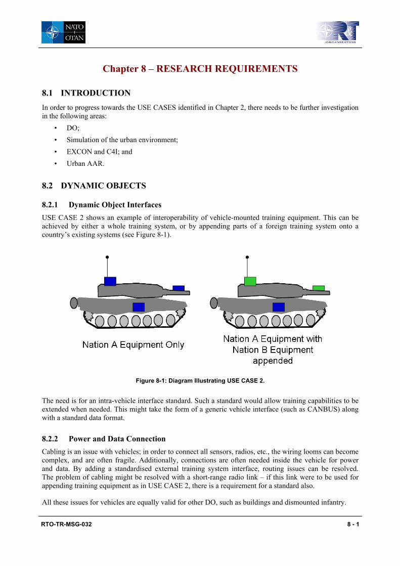
RTO-TR-MSG-032 8 - 1
Chapter 8 – RESEARCH REQUIREMENTS
8.1 INTRODUCTION In order to progress towards the USE CASES identified in Chapter 2, there needs to be further investigation in the following areas:
• DO; • Simulation of the urban environment; • EXCON and C4I; and • Urban AAR.
8.2 DYNAMIC OBJECTS
8.2.1 Dynamic Object Interfaces USE CASE 2 shows an example of interoperability of vehicle-mounted training equipment. This can be achieved by either a whole training system, or by appending parts of a foreign training system onto a country’s existing systems (see Figure 8-1).
Figure 8-1: Diagram Illustrating USE CASE 2.
The need is for an intra-vehicle interface standard. Such a standard would allow training capabilities to be extended when needed. This might take the form of a generic vehicle interface (such as CANBUS) along with a standard data format.
8.2.2 Power and Data Connection Cabling is an issue with vehicles; in order to connect all sensors, radios, etc., the wiring looms can become complex, and are often fragile. Additionally, connections are often needed inside the vehicle for power and data. By adding a standardised external training system interface, routing issues can be resolved. The problem of cabling might be resolved with a short-range radio link – if this link were to be used for appending training equipment as in USE CASE 2, there is a requirement for a standard also.
All these issues for vehicles are equally valid for other DO, such as buildings and dismounted infantry.

RESEARCH REQUIREMENTS
8 - 2 RTO-TR-MSG-032
8.3 EXCON AND C4I
8.3.1 Dynamic Object to EXCON Chapter 7 describes a standard for interface E1; Chapter 6 shows that in order to have a fully interoperable DO, interfaces E4 and E3/2 need standards. This will form the reporting system from each DO to EXCON, and remote system control functionality.
8.3.2 C4I Interoperability C4I systems can transmit data either at the platform level, via interface E4, or at EXCON via interfaces E6/7. It is not the remit of the UCATT TG to decide on standards for C4I system interoperability. There is however considerable investment in developing C4I interoperability standards, in particular within NATO. The MIP (although not a NATO body) is the current body that is charged with developing a standardised information exchange data model. This model is currently JC3IEDM Version 3.0. There are 26 nations and organisations involved in the development process and given recent decisions in the United States by both the U.S. Army and the U.S. Marine Corps to use the JC3IEDM as the interface between C2 and M&S it would seem the most logical starting place. As a result, JC3IEDM should be fully explored and where possible carried into the UCATT standard. Where JC3IEDM does not provide a means of exchanging data required to support training in an urban environment then extensions may need to be added or taken into the core JC3IEDM.
In addition within SISO there is a PDG that is focussing on C2-to-M&S interoperability and are developing a standard, Coalition Battle Management Language (C-BML). Within the NMSG, MSG-048 is tasked with assessing the phase 1 standard that the C-BML PDG are developing and it is possible that this standard will be applicable to a UCATT standard for exchanging data between urban training and C4I systems.
8.3.3 EXCON to EXCON An interface between different EXCON systems is required to fulfil USE CASES 3a and 4. This should allow for operations in different training areas to be interconnected at the command level. Interfacing at this level is most commonly encountered in computer simulation systems, e.g. DIS and HLA, and the United States are developing live training interface standards in the form of CTIA and TENA.
8.4 SIMULATION OF THE URBAN ENVIRONMENT
8.4.1 Best Practice for Urban Effects Simulation of the urban environment will encompass the determination of any effect and the representation of that effect. Chapter 6 has already noted that there is a need for standardised damage tables and for common simulation effects. In the urban environment, there is a need for a standard practice for representation of on-building effects. Interoperable or common damage tables are problematic due to the conflicting needs for unclassified data versus realistic weapon effects. Further research is required to define a set of standard weapon effects that can be ratified for international training events.
8.4.2 Common Terrain Fidelity If a geometric pairing system is to be used successfully in an interoperable environment, there needs to be a compatible process in determining engagements. This is driven by interoperable damage tables, mentioned above, and an interoperable simulation of the urban environment. The requirement is for standardised terrain database fidelity to prevent conflicts in engagement resolution.

RESEARCH REQUIREMENTS
RTO-TR-MSG-032 8 - 3
8.4.3 Common Human Representation Human representation is important in the urban training environment: Participants need to react to non-lethal weapons, and OPFOR should react to effects-based operations. There is a need for a standardised representation of human effects, such as suppression, to enable interoperability.
8.5 URBAN AAR
Given the complexity of the urban environment and the importance of good communication and control skills, AAR must provide sufficient information to allow an instructor to show evidence for the training audience. The nature of this evidence must be presented in a manner that is easy for a military audience to understand and assimilate. NATO standard symbology and mapping conventions exist for 2D representations (this includes “2.5D”; icons placed on to a 3D terrain). However, the visual complexity of the urban environment presents a great challenge to understanding of the battle space. Showing each individual is a method to comprehend the details of the battle, but this can quickly clutter a display. A common standard for symbology would allow entities to be aggregated by unit and/or by geographic location (i.e. within a building). There are existing NATO groups looking at common visualisation – AAR visualisation for urban operations needs to leverage from developments in these areas (e.g. IST-043 Visualisation and the Common Operational Picture WG).
8.6 CONCLUSIONS
The two main emphasises of this chapter have been on defining equipment interoperability for DOs, EXCON and C4I, and secondly for process standards, urban representation and training tools.
Equipment interoperability research falls into defining standards for military training data transfer, and physical standards for connectivity and safety. Both have the potential to leverage off other standards (e.g. JC3IEDM and C-BML) and international industrial standards (e.g. Bluetooth).
The representation of the urban environment is a training process issue, which needs to be addressed by the appropriate NATO group (most likely the TSWG and FIBUA/MOUT WG), with technical support from industry partners where required for modelling standards, etc.
8.7 RECOMMENDATIONS
The following areas are recommended for future research:
Research to be assigned to a follow on UCATT TG:
• Develop intra-DO interface standards.
• Develop EXCON to DO and EXCON to EXCON interface standards.
• Develop DO/EXCON to C4I interface standards.
• Define and ratify a set of expandable damage tables for representing urban effects.
Research to monitor, provide advice on and pull-through from other NATO research areas:
• Develop training process standards for multi-national interoperability.
• Develop AAR standards for common visualisation of training information.
RESEARCH REQUIREMENTS
8 - 4 RTO-TR-MSG-032

RTO-TR-MSG-032 9 - 1
Chapter 9 – RECOMMENDATIONS
9.1 INTRODUCTION
The UCATT TG in the preceding chapters of this report has made a number of recommendations to improve overall approaches to training in an urban environment. Although all recommendations have been agreed by the members of group, it is recognised that nations can and will each have their own, potentially diverse emphasises on their technical, operational or tactical needs. In addition, each of the different industrial members of UCATT have their own visions of what they see as a future urban training system related on their past R&D, legacy technical solutions and understanding of customer requirements. Regardless of these facts all of the recommendations that have been listed in this chapter are, as stated, commonly agreed and are intended to provide a common baseline for each nation in order to deliver interoperability and give industry direction in their respective efforts as well as future R&D in more focused areas.
9.2 RECOMMENDATIONS
In order to improve overall approaches to training in an urban environment the UCATT TG is making the following recommendations as listed in the sub-sections below.
9.2.1 Maintenance of UCATT Report The work undertaken by the UCATT TG and encapsulated within this report is based on a vision of urban operations as laid out in UO2020 [4] and the belief that:
• Nations will need to increasingly train for operations in an urban environment that will require the use of either national or other nations FIBUA/MOUT facilities as described in the USE CASES;
• Increasingly that training will be coalition; and
• Use technology that is currently or likely to be available in the 2020 timescale.
Although it is recognised that the context for military operations is changing and that what we expect today will be different tomorrow, it is clear that most operations will be conducted within an urban environment across the full spectrum of conflict and they will be joint. Therefore the work of the UCATT TG needs to be maintained and its report must be updated so that it will remain a valuable resource document and continue to guide national defence acquisition organisations and industry as they develop FIBUA/MOUT facilities through to 2020 and beyond.
The maintenance of the UCATT report can be conducted by a small group of UCATT TG members that would meet once every year to discuss and update the report based on a continued understanding of the military context, changes in technology and progress towards interoperability through the standardisation process.
9.2.2 Related Working Groups The UCATT TG has been concentrating on the area of training with simulators in the urban environment; however there are a number of other working groups in this important area working under the NATO umbrella. The UCATT report has to be recognised and taken into account by TSWG, FIBUA/MOUT WG and other RTA and NMSG task groups. Both combat and the war against terrorism will increasingly take place within the urban environment and therefore the need to train in this environment will increase in importance in future military training and the work that has been done in this area will contribute to the actions of the others. It is expected that this report will carry more weight, since the document has been

RECOMMENDATIONS
9 - 2 RTO-TR-MSG-032
produced – unlike many other reports – in partnership with members of industry who will ultimately deliver the required capability that is interoperable between nations.
9.2.3 Benefit and Continued Involvement of Industry Industry partners were invited to work within the UCATT TG and the benefit which they gained while providing their expertise was that those members of industry were able to form a closer relationship with those nations participating and their urban simulation experts. This has enabled industry to understand the user needs which should help to direct their own R&D work. This report will provide industry with guidance on areas where they should invest and by their participation it is hoped that nations will follow the guidelines in this report although it is recognised that there will be technological development and solutions which are beyond the group’s knowledge at the time the report was completed which will need to be considered when both industry and nation invest in urban training facilities. To deliver interoperability it will require industry to work together and it is hoped that they will continue to provide support for the development of the proposed standards and continue to participate in a future UCATT TG. It is also recognised that in looking at other areas in the constructive and virtual simulations areas that need to be integrated with the live environment that other industry participants may join a future UCATT TG.
9.2.4 Continuation of the UCATT TG The work of the UCATT TG is not finalised – a report is produced but there are a number of other areas that need to be examined in more detail. These areas include: laser standardisation, the use of virtual and constructive simulation in FIBUA/MOUT training, ER (e.g. coloured smoke), data communication, etc. A key area that will need more investigation in future urban military training is C4I systems and their connectivity with training systems. The TG is willing to continue the work with the same structural concept; working together with industry. A draft new TAP and TOR for UCATT 2 is at Annex K. Figure 9-1 is an elaboration together with NATO FIBUA/MOUT working group and is describing how the work of a new UCATT TAP will potentially contribute in the future. As the overall goal for UCATT work has been stated to be year 2020, also this figure will cover the different milestones until then [Section 4.6].
Figure 9-1: UCATT Continuation in the Context of Work by the FIBUA/MOUT WG.

RECOMMENDATIONS
RTO-TR-MSG-032 9 - 3
9.2.5 Standardisation of External Interfaces of the Functional Architecture Since the purpose of the UCATT TG is to set requirements for interoperability, it is recommended that the external interfaces defined in the functional architecture have to be standardised. In taking an architectural approach it is also recommended that the MooD software used to demonstrate how data can be captured and linked to requirements data into its associated database is used to develop the Functional Architecture. This will require funding support from MSCO/RTO in Paris [Section 4.6].
9.2.6 Standard Engagement Codes
9.2.6.1 Standard on Laser Communication The UCATT TG agreed on the urgent need of a standardised (laser) communication code. This UCATT code has to be an open code covering the information needs of modern simulation training. It needs to be free of company IPR, provided under Open Content License and standardised at the SISO/NATO level. When a decision towards a continuation of the UCATT TG is made, one of the focuses of this group must be the continuing support and survey of the code standardisation process [Section 7.4.1].
Industrial participants within the UCATT TG have been working on the first step towards standardisation of laser communication for Direct Fire Weapon Effect Simulation (DFWES). Their efforts can lead into the development of an open standard. This standard, which is presently today based on laser technology, can make interoperability between different national soldier/weapon systems possible.
The report contains examples of possible future code structures and ways to migrate legacy codes to a standardised UCATT code set. The UCATT TG recommends following the proposed migration path so that the process can be finished by 2020.
9.2.6.2 Non-Target Designating Code Addition The UCATT TG has identified the need for an extended NTD code portion. A future UCATT TG needs to pursue a compatible NTD code addition as this was not completed. This NTD addition would determine how to send TES data for non-target designating weapon systems.
9.2.6.3 Standard on Vulnerability
To avoid negative training effects and classification issues, a future UCATT TG proposes to develop standardised training vulnerability models that can be used instead of “classified” national vulnerability models during joint exercises. The overall UCATT architecture will nevertheless support the use of classified models in individual countries’ indigenous exercises.
9.6.2.4 Standard on Effect Representation (ER)
Effect Representation (ER) is a vital part of the engagement simulation process (see Chapter 7 for details). A common “ER-language” is essential for multi-national exercises. ER-needs and ER-means should be agreed upon by the FIBUA/MOUT WG and TSWG since they represent the user community and can evaluate possible solutions.
9.6.2.5 Standard on Data Communication Protocols
The UCATT TG has identified the need for a standardised data communication protocol on the level of the DO external interfaces. A future UCATT TG needs to pursue a common data communication interface in order to address the need for a common data communication. The standard should determine how to receive and evaluate incoming data. A future task should be to continue research on the data communication protocol, leading to the definition of the physical layer that transports the data.

RECOMMENDATIONS
9 - 4 RTO-TR-MSG-032
9.2.7 Continuous Review of the USE CASES A review and development of additional USE CASES with greater detail to support evolving training requirements is essential. A follow on UCATT TG plans to utilise the USE CASES as definitions for future experiments in support of the depicted standardisation efforts.
9.2.8 Funded Experiments The UCATT TG believes it is essential to conduct test experiments for the purpose of evaluation and validation of the standards in development for urban training technologies. These experiments would provide an iterative process through which standards and compliant systems may be developed. The funding of these experiments should be provided by the national defence organisations or by NATO ACT.
9.2.9 Site Register Update and Best Practice It is recommended that Site Register summary should be maintained and updated twice a year, after each meeting of the FIBUA/MOUT WG. The responsibility for administering the website lies with the FIBUA/ MOUT WG although support from a future UCATT TG would be available where technical details are needed. At present the UCATT TG have published its reports on this site but as this will be transferred to the RTO WISE site. It is recommended that in future only a link is provided to the RTO WISE site.
A separate questionnaire aimed directly at collecting best practice recommendations should be circulated by the FIBUA/MOUT WG and the result presented on the website. A future UCATT TG should continue to support the FIBUA/MOUT WG in collating a “Compendium of Best Practice”. The NATO Urban Operations Handbook could potentially incorporate best practice.
9.2.10 Training Facility Recommendation The identification of an overarching approach to train within each nation’s facilities, interoperability between training systems and devices of different countries, and supporting legacy training devices needs to be further investigated, along with the identification of the training requirements for urban operations in the areas of virtual and constructive.
The relationship with the FIBUA/MOUT WG was invaluable to the work of the UCATT TG because it provided contact with 25 NATO/PfP countries. In the event that the work of the UCATT TG is continued to examine the areas of virtual and constructive requirements and LVC integration then a more formalised relationship should be developed with the Army Sub-Group and both the FIBUA/MOUT WG and TSWG because they are key users and need to endorse future requirements.
9.2.11 Health, Safety and Environmental Health, Safety and Environmental requirements need to be examined to see if a common standard can be developed in appropriate areas.

RTO-TR-MSG-032 10 - 1
Chapter 10 – REFERENCES
[1] NATO Land Operations 2020 (NATO reference RTO-TR-8 dated 1999).
[2] Jones, Col S.M., U.S. Army, “Re-Examining Tomorrow’s Battlefield: Taking the Fight into the Cities”, Student Issue Paper, Centre for Strategic Leadership, U.S. Army War College, June 2003, Volume S03-01.
[3] Hahn II, Robert F., and Jezior, B., “Urban Warfare and the Urban Warfighter of 2025”, Parameters, Summer 1999, pp 74-86.
[4] NATO Urban Operations 2020 (NATO reference RTO-TR-071 – AC/323 (SAS-030) TP/35 dated April 2003).
[5] NATO Land Group 8 Military Operations in Urban Terrain (MOUT) Team of Experts (TOE) Report to NATO Land Group 8 – April 2002 dated 25 March 2002.
[6] Simulation Interoperability Standards Organization, “Balloted Products Development Process”, SISO-ADM-003-2005.1, 26th August 2005.

REFERENCES
10 - 2 RTO-TR-MSG-032

RTO-TR-MSG-032 A - 1
Annex A – LIST OF MEETINGS AND OBJECTIVES
Serial Date Location Objectives
1 11-13 June 2003 The Hague, Netherlands
Agree task plan
Identify preliminary requirements
Develop USE CASES
Develop MOUT site register plan
2 13-15 Sept. 2003 Paris, France Refine USE CASES
Develop capability requirements matrix
Review status of MOUT site register
3 4-5 Dec. 2003 Orlando, USA Mapping of requirements to UO2020
4 22-23 April 2004 Shrivenham, UK Complete USE CASES
Work on capability requirements matrix
5 September 2004 Stockholm, Sweden Identify logical components and develop draft functional architecture from USE CASES
Finalise capability requirements matrix
Review MOUT site register
6 6-7 Dec. 2004 Orlando, USA Review functional architecture and sub-systems
Review definitions of functional sub-systems
Review interfaces between sub-systems
Establish internal and external interfaces to functional sub-systems
7 24-28 April 2005 Amsterdam, Netherlands
Review capability requirements matrix
Review interfaces between sub-systems
Develop external interface data sets
8 26-28 Sept. 2005 Walenstadt, Switzerland
Identify interoperability elements
Draft interoperability report
9 27-29 Nov. 2005 Orlando, USA Develop report structure
10 15-19 May 2006 Farnborough, UK Develop interoperability specification
Discuss best practice, site register
11 4-6 Sept. 2006 Amsterdam, Netherlands
Draft task group report
12 7-8 Dec. 2006 Orlando, USA Finalise task group report

ANNEX A – LIST OF MEETINGS AND OBJECTIVES
A - 2 RTO-TR-MSG-032

RTO-TR-MSG-032 B - 1
Annex B – TEAM OF EXPERTS REPORT TO LAND GROUP 8
_______________________________________________ _____________________________________
NORTH ATLANTIC TREATY ORGANIZATION
25 March 2002
Reference: ##
NATO LAND GROUP 8 MILITARY OPERATIONS IN URBAN TERRAIN (MOUT) TEAM OF EXPERTS (TOE) REPORT TO NATO LAND GROUP 8 - APRIL 2002
Reference: NATO Land Operations 2020 – (NATO Reference RTO-TR-8)
“By 2010 75% of the world’s population will live in large urban areas.
ERGO
Cities are the most likely battlefields in the 21st Century”
Netherlands Defence Science Board
“There is no Western technological dominance on the Urban Battlefield”.
Maj. Ronald Poetiray RNLMC

ANNEX B – TEAM OF EXPERTS REPORT TO LAND GROUP 8
B - 2 RTO-TR-MSG-032
ABSTRACT
1. This aim of this paper is to report on the findings of the activities of the NATO LG/8 Military Operations in Urban Terrain (MOUT) Team of Experts (TOE). The subject of the paper is to identify areas in which potential MOUT Training solutions may benefit from standardisation thus enhancing interoperability between nations. The move into live simulation has produced no real interoperability standards over the last 15 years. The growing importance of live simulation and the deeper integration of allied forces in training may require a degree of system interoperability. A number of MOUT simulation applications or sub-systems lend themselves to being better defined and investigated as possible areas for standardisation. The MOUT TOE invited representatives from industry to share their thoughts as to future developments. In return the MOUT TOE proposes to better define the NATO User requirement.
2. The paper is intended for consideration by NATO LG/8 at the Spring Meeting of LG/8 2nd Week in April). This paper acts as a summary of progress to date and makes recommendation to LG/8 regarding the potential for possible NATO sponsored practical Programmes of Work (POW).1
INTRODUCTION
3. A Changed Environment. By 2010 75% of the world’s population will live in large urban areas. These urban areas will have many different characteristics according to their location, function and ethnic makeup. However, a major factor they will have in common is the growing tendency to be used as a combat arena. The difficulties of conducting military operations in Urban terrain are well documented and litter the pages of recent history including Stalingrad 1942, Hue City 1968 and Palestine 2002. In general MOUT is expensive in military manpower and high in casualties to both military and civilian alike. Urban environments also degrade the use of current weapon systems due to limited arcs, visibility and importantly the existence of a civilian population2 and resultant restrictive Rules of Engagement.
4. The Capability Gap. The problems and limitations associated with developing training environments to better enable MOUT are only just beginning to be understood as first generation systems are fielded. Whilst Combat Training Centres (CTC) making use of laser Tactical Engagement Systems (TES) for force on force manoeuvre & combat are becoming “de rigeur” for most Western nations, the ability to conduct meaningful training within the MOUT environment is limited. There is a growing interest amongst NATO nations into developing training solutions for better MOUT training. Current TES have limited applicability for MOUT due to shorter ranges and associated beamwidth/sensor density. The range of pyrotechnic effects is also limited and certain weapon types are not represented. Additionally, the need to provide training experience is missing.
5. NATO Response. NATO Land Group 8 (LG/8) Simulation Interoperability for joint training and operational support, formed a Team Of Experts (TOE) to investigate the MOUT training problem in conjunction with industry and relevant research authorities. NATO LG/8 has the remit to anticipate future training requirements and to shape future policy in line with extant Defence Capabilities Initiative (DCI) EE93 and relevant NATO training policy documents/papers.4 Current military requirements focus on the development of standardisation for virtual and constructive simulations. However, there is growing recognition between the Group members that live simulation standards have been neglected for some time,
1 The timeframe for this report may enable discussion and possible approval of practical investigations to be made
at the NMSG Fall 02 Mtg. 2. Whilst an “enemy” civilian population may not be friendly in the sense that they aid an invader, their status as
civilians protects them under the Geneva Convention and basic laws on human rights. 3. Defence Capabilities Initiative (DCI) EE9 – “Develop and implement operational simulation devices within the
NAAG by identifying standards and seeking opportunities for collaboration between nations 4. Currently, Land Operations 2020, SHAPE – NATO policy for Training, Evaluation and Exercises & NATO
Modelling and Simulation Master Plan

ANNEX B – TEAM OF EXPERTS REPORT TO LAND GROUP 8
RTO-TR-MSG-032 B - 3
hence the focus on MOUT. The MOUT TOE restricted itself to examining potential areas of interoperability within future training system solutions and also sought to identify and make contact with NATO Military User Groups in order to provide coherency to the investigation. In line with current NATO practice, the TOE met three times during an initial 12 month period in order to examine feasibility prior to making a report and recommendation to the parent body, NATO LG/8.
AIM
6. Aim. The NAAG Land Group (LG) 8 MOUT TOE set itself the following task:
“To investigate and recommend a generic set of unclassified requirements to be made available for all NATO/PfP nations to inform requirements and standards for development of instrumented MOUT capability. The generic requirement will specify and detail interface requirements”.
The specific aim of the MOUT TOE was to see if this investigation was practicable and if so to recommend to NATO LG/8 a way ahead/Programme of Work (POW).
LG/8 MOUT TOE – SUMMARY OF ACTIVITY
HELSINKI –OCT 01
7. Helsinki – Oct 01. The first meetings of the NATO MOUT TOE took place in Helsinki, Finland over the period 5 –10 Oct 01:
a. MOUT TOE NATO Members Pre-Meeting – 5 Oct 01. This meeting sought to confirm how the MOUT TOE would operate and to identify potential areas for NATO standardisation. These specific areas relate to areas where either Government/NATO Furnished Information could be applied or where standardisation does not constrain potential industrial solutions:
(1) Laser Information Coding, Positional Reference, Percentage Kill (PK) Frequency/Bandwidth Issues, Weapon Effect, Timestamp for engagement. Power, After Action Review, Standard Application Programmable Interface (API), Binary Laser Code for Projectiles, etc.
(2) The pre-meeting also recognised that there were areas in which Subject Matter Expertise (SME) is required in order to assist the TOE:
(a) STANAG for Laser Safety. Eye safety especially relating to GaAs sensors in the range .9-1.1um.
(b) Future Proofing. Ongoing developments into instrumented range facilities to ensure future proofing of interoperability standards.
(3) The pre-meeting concluded that SHAPE/NC3A were the legitimate end users of the products. SHAPE was supportive of the drive toward a “MOUT” STANAG and the NATO Training Simulation Working Group (TSWG) was seen as representative of national User requirements.
b. MOUT TOE – 8-10 Oct 01. The main meeting focused on examination of the potential for harmonisation of user requirements for the future MOUT environment5. In the spirit of openness
5. For future read 10-15 years hence circa 2015.
ANNEX B – TEAM OF EXPERTS REPORT TO LAND GROUP 8
B - 4 RTO-TR-MSG-032
and trust, industrial participants were invited to share commercial-in-confidence information with the Government representatives. This first meeting between User representatives and industrial was generally thought to be a good idea as it created an informed arena for continuing dialogue regarding future MOUT technical challenges circa 2010/2020. It was felt that there were potential areas for standardisation and that NATO (amongst other agencies and user groups) needed to support such a venture. A number of detailed industrial presentations were delivered. Industry saw a generic set of requirements for future MOUT as being helpful to better focus their efforts but a note of caution was sounded regarding the desire to be too overly prescriptive thus constraining novel ideas and applications.
ORLANDO – DEC 01
8. Orlando – Dec 01 - General. The second meeting of the MOUT TOE was held on 27th Nov 2001 at the US Army Simulation Training and Instrument Command (STRICOM). The meeting followed the same format as the Helsinki Meeting, namely an introduction by NATO as to the aims and objectives of the MOUT TOE followed by presentations from industry as to the perceived way ahead. Of particular interest to the MOUT TOE was the US Army STRICOM vision for future training for which sought evolutionary progression to ensure that the training support will become much more interoperable through current initiatives including:
a. Common Training Information Architecture (CTIA). Defining the products that will be needed to provide for that level of interoperability. Working between live, virtual and constructive simulations. An ongoing research programme.
b. “One TES” (Tactical Engagement Simulation (generic term for MILES). Within US there are many variants of TES. “One TES” is seen as the evolving standard to best define the future standards.
9. Orlando – Discussion Topics. Some themes raised at Helsinki were further discussed and areas for interoperability examined:
a. Generic NATO set of Tables for Vulnerability, Lethality. A common set of tables for vulnerability/Lethality would assist interoperability. This is “doable” and will assist industry.
b. Health and Safety. Laser standards regarding health and safety are not consistent between NATO nations.
c. Physical Transition between Open and Restricted Environments. Many MOUT facilities are being designed as integral parts of Combat Training Centres (CTCs). This may imply specific MOUT simulation solutions, which are not applicable to more open terrain where current TES systems operate. In the future, will there be two diverging technologies at play?
d. Frequency Requirements for Instrumented Ranges. The frequency requirements for instrumented ranges may not be universally applicable due to national bandwidth constraints.
e. Quantification of Training Standards. The NATO aspiration to quantify training standards will likely lead to some form of standardisation of test exercise and After Action Review process. This process standardisation for training is still in a nascent form.
10. Orlando – Summary. In summary:
a. “De-facto Standards”. The evolving US standards for instrumented ranges (CTIA) were recognised.

ANNEX B – TEAM OF EXPERTS REPORT TO LAND GROUP 8
RTO-TR-MSG-032 B - 5
b. Areas for Standardisation. Certain areas such as Ph/Pk may offer themselves open to standardisation within NATO to enable meaningful force on force training in pursuit of further quantifying training benefit.
c. Subject Matter Expertise. The need to involve further SMEs was understood, especially relating to specific issues such as Health and Safety.
THUN – FEB 02
11. Thun – Feb 02 - General. The 3rd Meeting of the NATO Military Operations in Urban Terrain (MOUT) Team of Experts (TOE) was conducted in Thun, Switzerland over the period 5-8 Feb 02. The meeting was in two parts:
a. A pre-meeting on Tue 5th Feb of NATO/PfP LG/8 delegates which agreed the agenda and method of working for the main meeting.
b. The main meeting (Wed 6th – Fri 8th Feb) further examined the nature and scope of the MOUT training capability gap and explored areas that may benefit NATO/PfP nations by adopting some form of standardisation of equipments and/or procedures.
12. User Focus. Of interest at Thun, was the number of User briefings given which exposed some of the limitations of current MOUT Training:
a. Lack of Variety of Urban Terrain Types/Inability to Support the All Arms Battle. A major limitation in MOUT was the lack of variety of urban terrain types and ability to support the all arms battle i.e. Artillery and Armour representation in simulation. A possible way to better replicate urban terrain types in terms of size, area and types of building may be representation in the virtual world augmenting current live elements. However, the limitations of the virtual world are themselves recognised. Urban Ops are not purely infantry but infantry is the current focus for simulation. The UK experience of WW2 showed that towards the end of the war, firepower became the dominant factor in MOUT. The role of the man in individual FIBUA skills became secondary to better and more co-ordination of other battlefield assets. The shock effect of armour, the use of artillery & air all need to be replicated within MOUT training facilities of the future or else false lessons may be learned.
b. Limitations in technology/TES equipment to support FIBUA.6 Too many simulation systems and new technology can serve to distract uses from the “job in hand”. An example - Virtual technology was seen as the de-facto means of training some yeas ago; the reality nowadays is somewhat different.
c. Lack of opportunity to train at formation level.7 Most nations live MOUT facilities can only cope with a company sized group or Battle Group at best. However, formation level is perceived as being a critical level of command and resourcing MOUT. There is little opportunity for testing this level of command less than in the constructive environment. It may be that the fusion of the live/constructive world is a positive step in initially addressing this problem
d. Home Station Training. Individual MOUT training is required at homestation not purely at Combat Training Centres (CTCs).
6. Laser cannot shoot through walls, opportunities for TES cheating, ability to portray tank and artillery rounds etc.
Battlefield Effects. 7. Lack of opportunity to train above unit level. There is a need to portray Brigade level operations.

ANNEX B – TEAM OF EXPERTS REPORT TO LAND GROUP 8
B - 6 RTO-TR-MSG-032
e. Merging of Tactical/Operational Levels of Warfighting. The “distance” between tactical and operational levels within MOUT is fast becoming minimised. Development of doctrine is required to recognise this closing gap.
f. Emerging Threats. There are a number of emerging threats that will profoundly alter the way we conduct MOUT. Of note is the growing use and widespread availability of Thermobaric weapons – “overpressure weapons”. These are weapons that are optimised for blast and have a longer effect then conventional High Explosive. The use of these weapons will render conventional tactics, training and procedures for MOUT largely obsolescent.
13. NATO Organisation and the Relationship between NATO MOUT/FIBUA Groups. The relationship between the three identified groups that had specific Urban training (simulation) responsibilities was discussed. NATO LG/8 MOUT TOE was seeking a representative NATO group that could act as a focus for User MOUT requirements. Both the Training Simulation Working Group (TSWG) and the MOUT/FIBUA WG Chairmen were present at the meeting8 and an outline relationship discussed.
RELATIONSHIP WITH OTHER NATO GROUPS
14. Research Technology Board (RTB) – SAS Groups. One Research Technology Board (RTB) SAS study has been identified which will provide LG/8 MOUT TOE with a guideline for future activity: NATO-SAS 30 Study “Military Operations in Urban Terrain in 2020”.
15. NATO Training and Simulation Working Group (TSWG). The need to define the relationship, establish liaison and de-conflict with other groups working in the MOUT field is paramount. The NATO Training and Simulation Working Group (TSWG) [Doctrinal – and User focus] & the FIBUA/MOUT WG [Operational requirement provider] are key elements in the LG/8 work to develop interoperability standards. Both the TSWG & FIBUA/MOUT WG report to the Army Simulation Group (ASG) under the NATO Training Group. It was agreed that the “formalisation” of the relationship with respect to the specific MOUT/TOE work, through the respective NATO chains of command, should be an action conducted by the NATO LG/8.
IDENTIFIED ISSUES & POTENTIAL AREAS FOR INTEROPERABILITY
16. General. A number of potential interoperability areas have been identified by the MOUT TOE, and are assessed to be worthy of follow up investigation and activity:
a. Operational Concepts. A User led group that would examine common user requirements for the timeframe 2010, Tactics, Training and Procedures.
b. Battlefield Effects. An investigation onto pyrotechnics techniques & visual cueing, collateral effects (shooting though walls – effects of artillery/armour.
c. Exercise Control (EXCON) /After Action Review (AAR). Formalising the concept of AAR, quantification of training benefit ergo requirement to capture certain information.
d. System Architecture. The generic architecture for future systems – interfaces with communivcations/C4I systems. Compatibility with Land Operations 2020 concept.
17. Operational Concepts. There is a recognised overall capability requirement and gap for MOUT/FIBUA training but these requirements differ between nations. Greater harmonisation of User requirements and doctrine is necessary before proceeding to standardisation of equipment and procedures.
8. Lt. Col. L Cyr CA and Maj. A Rule UK respectively.

ANNEX B – TEAM OF EXPERTS REPORT TO LAND GROUP 8
RTO-TR-MSG-032 B - 7
An investigation into Mission Essential Tasks is required. A potential action placed on LG/8 was to request ASG to conduct this study – possibly through the MOUT/FIBUA WG.
18. Battlefield Effects. Tactical Engagement Simulations (TES) capability should be a specialist sub-set of Battlefield effects. TES capability should examine Laser Code, class and vulnerability9 code to ensure interoperability. There is a fundamental requirement to achieve common objectives between nations in the following areas:
a. TES Interoperability. Three levels of TES interoperability are envisaged:
(1) To borrow/use existing equipment from other nations i.e. NL troops borrowing GE equipment when training at GE facility.
(2) To develop interoperability between existing TES. Adapt current equipment – 2010 is a realistic date for this to be achieved.
(3) Development of common standards and new TES equipment. Only really an option by 2020.
b. Sensory Cueing. Sensory cueing as close as possible to reality. Visual, audio, shock, Haptic/tactile, Pressure, smell, effects of direct and indirect fire, explosives, Non-Lethal weapons, NBC.
c. Pyrotechnics. The major issue here regards safety regulations and common representation of effects.
19. EXCON/AAR. Essentially, EXCON conducts the following; planning, preparation, conduct, preparing and providing an interactive AAR (provides feedback, is interactive, objective and flexible). Major issues and potential areas for interoperability include:
a. The need to minimise training staff particularly Observer Controllers in the field.
b. The requirement to capture all data10 to provide situational awareness and statistical analysis.
c. The consequent need for smart tools to present the right information at the right time, in the right format.
A possible way ahead is to incorporate a Synthetic Environment (SE) to provide contextual information i.e. platoon in MOUT operates within a company context. An SE also provides means of examining “what ifs” – from a set point alternative actions and outcomes can be postulated. Integration of training functionality with operational equipment is necessary but there is a need to avoid data contamination between the two domains. A conclusion was the need to seek wider collaboration with industry e.g. entertainment industry working in Virtual Reality (VR).
20. System Architecture. The system architecture is the common core for all applications. The service core includes protocols, data collection & storage. A common object interface required connecting with applications; EXCON, AAR, Video, targetry etc. The feeling is that nothing is impossible but the will is to solicit consensus between nations. However, an objection to this approach was the perception that 9. Dividing into laser classes is done in different ways in the US & Europe. The US tolerates a 4 times higher figure
than Europe. 10. For example; accurate position of individuals and units, weapon directions, contacts, resulting damage, communication,
C4ISR, observation arcs, logistical expenditure, CSS etc.

ANNEX B – TEAM OF EXPERTS REPORT TO LAND GROUP 8
B - 8 RTO-TR-MSG-032
industry would be micro-managed by Government and their role is relegated to supplying objects to be hosted on the common object architecture.
SUMMARY
21. LG/8 exists to promote the use of standards to aid interoperability. There is a fine balance between timely standards and constant innovation from industry. However, the meetings of the MOUT TOE opened up a constructive dialogue with industry and identified actions NATO can take to move toward interoperability.
22. It was recognised that the demands of industry with regard to commercial secrecy are reasonable and practical. It is hoped that these constraints on open dialogue will not prevent the definition of generic operational requirements for future MOUT.
23. A number of important areas may offer potential for future activity to support greater interoperability:
a. A revision of health and safety issues with respect to constraints imposed on developing a full range of battlefield effects.
b. Investigation into the vulnerability models used by different nations if force on force training is conducted using individual nation’s equipment is seen as a potential first step in interoperability for 2010.
c. Need to provide a consistent view of operational requirement for MOUT training in the timeframe 2010. This requirement is not seen as a NATO LG/8 but a NATO ASG responsibility. d. Capture of key data points derived from essential tasks in order to quantify training standards. These key data points will define the information capture requirement. Again this is a user led investigation to define together with training experts what elements have to be carried out and to what standard to satisfy the conduct of these tasks. e. Specific key (legacy solution) areas such as: weapon effects, weapon laser coding, system interface(s), AAR.
CONCLUSIONS & RECOMMENDATION
24. Conclusions. The NATO LG/8 MOUT TOE has come to the conclusion that:
a. There are sufficient areas of interest where standardisation would add value to recommend continuing the activities of the group.
b. There is a requirement to formally identify and stimulate a representative User group to act as a focus for the work.
c. There are sufficient areas of potential interoperability for practical investigation by NATO bodies and agencies such as NC3A and NMSG.
25. Recommendation. The recommendation from the LG/8 MOUT TOE is that a NATO MOUT Simulation WG be formed to conduct in depth examination of identified MOUT TOE issues.

ANNEX B – TEAM OF EXPERTS REPORT TO LAND GROUP 8
RTO-TR-MSG-032 B - 9
WAY AHEAD
26. Proposed Way Ahead. Subject to approval by NATO LG/8, the proposed output of the MOUT Simulation WG should be a technical document and briefing to NATO after a period not exceeding 2 years. The intention will be to investigate certain emerging technologies that offer benefit to simulation systems addressing MOUT, standardise areas for future MOUT and potentially improve the interoperability between nations (should that be required). The technical document will focus on best practice, draft technical solutions, and if possible recommend open standards.

ANNEX B – TEAM OF EXPERTS REPORT TO LAND GROUP 8
B - 10 RTO-TR-MSG-032

RTO-TR-MSG-032 C - 1
Annex C – RESULTS OF QUESTIONS SUBMITTED TO FIBUA/MOUT WORKING GROUP ON USE CASES
C.1 INTRODUCTION These are the results of the 10 questions submitted to the FIBUA/MOUT Working Group (WG) in April 2004 on the USE CASES described in Chapter 2. The answers provided an important cross-check of the USE CASES identified by the UCATT WG and the “needs and tasks”, identified in the FIBUA/MOUT WG.
C.2 RESULTS
Questions USE CASE 1:
Live MOUT training – Multi-national force
on national site
USE CASE 2:
Use other nations training facility
and staff
USE CASE 3a:
Distributed combined training
USE CASE 3b:
Combined training in mission area
USE CASE 4:
Command and staff training for engagements in
different mission areas
1) What objective(s) do you think the commander would like to train?
• PSO/PEO • Landscape • Social environment
(language, economy, laws, traditions)
• Population • Political situation • Factions • Logistics • Team building:
• Coordination • Communications • Rules of
engagement
• Destroying UAV/ Robots/etc.
• Co-operation/ working together/ team building/ procedures within staff, commanders lines, units (functional and technical)
• Train/rehearse doctrine and ROE, if gaps are discovered, procedures should be extended
• Peace-keeping during election period
• Interoperability ground-sea-air and nations/unit levels
• Staff training • Train your
intelligence staff • Checkpoint • Crowd control • SWAT • Security controls
(entrance to voting places)
• Train staff in the way the commander operates
• How he wants to be organised
• Information flow • Understanding of
doctrine and procedures

ANNEX C – RESULTS OF QUESTIONS SUBMITTED TO FIBUA/MOUT WORKING GROUP ON USE CASES
C - 2 RTO-TR-MSG-032
Questions USE CASE 1:
Live MOUT training – Multi-national force
on national site
USE CASE 2:
Use other nations training facility
and staff
USE CASE 3a:
Distributed combined training
USE CASE 3b:
Combined training in mission area
USE CASE 4:
Command and staff training for engagements in
different mission areas
1) What objective(s) do you think the commander would like to train? (cont’d)
• Task Force • Organisation
(chain of command)
• House clearing • Patrolling • CRC (crowd riot
control) • Information war
(cyber space)
• Train/rehearse the specific mission, scenarios (aspects are plans, assets, units)
• Escorting convoys and people
• Close air support • Evacuation
2) What kind of risks does the training eliminate?
• BLUFOR identity, (reduce personnel losses, equipment damage)
• Interaction within the units
• Miscommunication • Escalation of power
(show of force, controlled reaction)
• Eliminate enemy technical threats
• Own casualties • Keep hostage alive
• Misunderstanding, misinterpretation of each other / mission / commander’s intent
• Weak elements in the planning
• Improper use of assets
• Prevent situations getting out of control
• Keeping law and order
• Keeping the troops calm
• Prevent misunderstanding between troops
• Build up the minds • Not to have the
right information • Not to over-react • To bring everybody
on the same level and understanding of the situation
• Ensures staff understands how commander operates
• Provides clear understanding of the organisation
• Establishes work process and information handling
• Common understanding of doctrine and procedures
• Logistic problems • ROE inconsistencies • Misunderstanding of
national capabilities

ANNEX C – RESULTS OF QUESTIONS SUBMITTED TO FIBUA/MOUT WORKING GROUP ON USE CASES
RTO-TR-MSG-032 C - 3
Questions USE CASE 1:
Live MOUT training – Multi-national force
on national site
USE CASE 2:
Use other nations training facility
and staff
USE CASE 3a:
Distributed combined training
USE CASE 3b:
Combined training in mission area
USE CASE 4:
Command and staff training for engagements in
different mission areas
2) What kind of risks does the training eliminate? (cont’d)
• Govern the basic skill on each level
• To be sure on the ROE
• To be killed
3) What type of actions/situations would you like to train for?
• Checkpoints (vehicle/people searches)
• Objective approach • Crowd control • House clearing • Refugees • Rural and terrorist
operations • Patrolling • NBC • Protection of Red
Cross aid • Train new police
force
• Entering and fighting in a modern building
• The whole spectrum: • Peace-keeping/
peace-enforcing • High intensity
conflict / urban ops / asymmetric warfare
• Non-combatant evacuation
• Humanitarian relief ops
• Hostage rescue ops
• Adapted for each level, single and joint (army, navy, air force)
• Riot control (day/night)
• Rules of engagements • Check-points • Search operations
(house, vehicles, ships…)
• Staff training • Communication • Patrolling urban areas • Patrolling urban
seaside, harbour (Navy)
• How to support the organisation of election
• Practice planning • Course of action
analysis • Decision process • Dissemination of plan • Plan execution and
monitoring

ANNEX C – RESULTS OF QUESTIONS SUBMITTED TO FIBUA/MOUT WORKING GROUP ON USE CASES
C - 4 RTO-TR-MSG-032
Questions USE CASE 1:
Live MOUT training – Multi-national force
on national site
USE CASE 2:
Use other nations training facility
and staff
USE CASE 3a:
Distributed combined training
USE CASE 3b:
Combined training in mission area
USE CASE 4:
Command and staff training for engagements in
different mission areas
3) What type of actions/situations would you like to train for? (cont’d)
• Support the CIMIC/NGO activities (logistics/medics)
• Worst case scenario, rapid reaction force
• Insertion of snipers, recon, HUMINT, etc.
• Support from Air/Navy
4) What are the most important training moments for the individual soldiers/ units?
• Self defence • Threats • Communications • Live firing • Contact with local
people (establish rapport)
• Unwarranted attacks • Decisive actions
• Close in on the enemy
• Opening a building • Worse case scenario • Fighting with
integrated IT environment
• To experience the transition from the training situation to the “real situation” as close to reality as possible (at distributed locations)
• Soldiers: • Basic skills • Situation
awareness (ROE)
• Social and political environment
• Units: • Working together • Capability (100
against 100,000) • Where are our
limits? • Understanding the
situation and keeping focussed on the task
• Minimise use of force
• Gain understanding of the overall command process that will be in place once deployed (gathering and sharing background information)
• Gain an awareness of the capabilities of each nations forces assigned
• Gain an understanding of how the staff intends to operate (collaborative planning process)

ANNEX C – RESULTS OF QUESTIONS SUBMITTED TO FIBUA/MOUT WORKING GROUP ON USE CASES
RTO-TR-MSG-032 C - 5
Questions USE CASE 1:
Live MOUT training – Multi-national force
on national site
USE CASE 2:
Use other nations training facility
and staff
USE CASE 3a:
Distributed combined training
USE CASE 3b:
Combined training in mission area
USE CASE 4:
Command and staff training for engagements in
different mission areas
4) What are the most important training moments for the individual soldiers/ units? (cont’d)
• Operating efficiently (event driven practice)
• Analyze and assess performance (prepare and conduct AAR)
5) Make a time schedule of this exercise, Planning, Preparation, Exercise, AAR?
• Schedule block time for the range
• Staff – build multiple scenarios within first 2 weeks
• 1 week training of basics engagement skills
• 1 week joint training • 1 week on attack
procedures/process • Ensure targetry has
right silhouettes available and sufficient supply
• Expedite the AAR turn time, use results for additional training requirements
• Preparatory planning (Can be weeks before): • Schedule period • Intel gathering
(photos, building, area, weather, etc.)
• Preparation (Can be weeks before): • Developing
scenario, OPORD, etc.
• Coordination with Swiss training centre
• Basic training with ADL and SIM
• There should be several exercises, from low (unit) level to CJTF, to include staff exercises
• Planning and preparation should be as short as possible
• Exercises should be as intense as is possible
• AAR should be delivered as quickly as possible (multi- level)
• Schedule • D-45 Scheduling
training • D-35 Staff training,
basic skills • D-25 Unit training
(staff integrated) • D-15 Examine,
rehearsal • D-10 Training and
preparing theatre area • D-0 Be prepared
• Does not drive training requirements
• D-130 Stand up Bde HQ
• D-120 Train Bde HQ • D-60 CPX I at
Bde/Bn level/AAR following
• D-30 CPX II/AAR following
• D-Deployment

ANNEX C – RESULTS OF QUESTIONS SUBMITTED TO FIBUA/MOUT WORKING GROUP ON USE CASES
C - 6 RTO-TR-MSG-032
Questions USE CASE 1:
Live MOUT training – Multi-national force
on national site
USE CASE 2:
Use other nations training facility
and staff
USE CASE 3a:
Distributed combined training
USE CASE 3b:
Combined training in mission area
USE CASE 4:
Command and staff training for engagements in
different mission areas
5) Make a time schedule of this exercise, Planning, Preparation, Exercise, AAR? (cont’d)
• Breakdown of training: • Day 1: Training in
use of own electro tech equipment
• Day 2: Individual drills in urban fighting
• Day 3: Group training
• Day 4: Task related • Day 5: Task related • Every day an AAR
will be conducted
6) Do you think it is necessary to train together as a task force? (Explain your answer)
• Absolutely as the task force must understand how each other operate in order to identify the weaknesses/ capabilities of each other. This will help establish the training objectives that must be accomplished
• Yes it is necessary, because we always have to do. For example: • To work together
with helicopters for entering the house from the top and/or by coming down by rope
• Yes, “train as you fight”
• Yes • Staff training up to
brigade level • Live training up to
company (battalion) level
• Yes, because we have: • Different
languages, TTPs, systems, logistics
• Yes in order to achieve operational effectiveness you must train together prior to operational deployment
• Ideal solution is centralised staff, optional is distributed)

ANNEX C – RESULTS OF QUESTIONS SUBMITTED TO FIBUA/MOUT WORKING GROUP ON USE CASES
RTO-TR-MSG-032 C - 7
Questions USE CASE 1:
Live MOUT training – Multi-national force
on national site
USE CASE 2:
Use other nations training facility
and staff
USE CASE 3a:
Distributed combined training
USE CASE 3b:
Combined training in mission area
USE CASE 4:
Command and staff training for engagements in
different mission areas
6) Do you think it is necessary to train together as a task force? (Explain your answer) (cont’d)
• Need to understand different national procedures/ equipment, special compositions of forces
• To work together with a doctor/ medical squad/ section
• To work together with an engineer platoon/troop
• To work together with a CIMIC
• Mainly staffs but also be able to support/ reinforce units
7) Do you think that this USE CASE is or will be a realistic scenario?
• Yes, however the task force identified is too small. Would also need to know how long the operation will last?
• Could be • Yes • All 15 million people in one city? Is not really realistic, even if it is about historical reasons
• Yes. But need more units to solve
• Yes but needs to be more precise in wording
8) Could you describe (in headlines) the training system that you would like to have for this training (2 slides
• OPFOR (force on force capability)
• Live fire training • Fully instrumented
indoor/outdoor system
• Staff and commanders should be training different scenarios
• Advance TES (non-laser based), to shoot through walls
• NLW • Live/virtual training
facility
• Embedded exercise control at all levels (e.g. data capture, integrate several local situations into one common scenario)
• Layered exercise control: • Distributed staff
(including C-CJTF)
• Staff training – multi-media training system (online video, online pictures on a constructive/virtual training system, or embedded system in our C4I with access to public information sources
• Distributed • Secure • Real time voice and
video to emulate tactical comms
• Full tactical digital information exchange
• Common operational lexicon

ANNEX C – RESULTS OF QUESTIONS SUBMITTED TO FIBUA/MOUT WORKING GROUP ON USE CASES
C - 8 RTO-TR-MSG-032
Questions USE CASE 1:
Live MOUT training – Multi-national force
on national site
USE CASE 2:
Use other nations training facility
and staff
USE CASE 3a:
Distributed combined training
USE CASE 3b:
Combined training in mission area
USE CASE 4:
Command and staff training for engagements in
different mission areas
8) Could you describe (in headlines) the training system that you would like to have for this training (2 slides) (cont’d)
• Task force to build upon those scenarios
• Interactive training (tactical training for the task force)
• Perhaps a language conversion system (Interpreter device)
• Add BUGALAND virtual environment to scenarios, if possible
• Mobile training systems to take to BUGALAND (mission area)
• National staff elements
• National units • Highly automated
AAR functions to minimise training staff personnel
• Integration between live and virtual. Only down to certain levels (e.g. company/ squadron)
• Unit training – Live training system which allows to train to the engagement of all engaged weapon systems including non-lethal weapons, etc., in urban environment
• Staff trainer – Computer Assisted Exercises (CAX)
• PsyOps • Force-On-Force
trainer system (laser)
• Reliable exercise comms and network
• Comprehensive and compatible constructive simulation
• Common terrain and environment database
• Exercise management system
• Capability to prepare and distribute AAR to training audience
9) Make a list of interoperability aspects?
• Command, Control, Communication, Computers, Intelligence, Reconnaissance (C4ISR) systems
• Logistics • Command and
Control • Sight Recognition
(presentation devices)
• High speed data • Coded data (security) • TES • Non-laser based
• C4I interoperability is given/assumed
• Supply/medivac procedures, also legal aspects of cross supply (for example use of ammunition)
• Data-exchange between national training sites and C4I systems
• C4I training system (for staff training)
• Interoperability with WESS and TESS
• C4I • ROE • Training systems • Tactics/techniques/
procedures (TTP)
• C4I information sharing
• Training information sharing
• System performance to support common environment and terrain database
• Language translation and interoperability
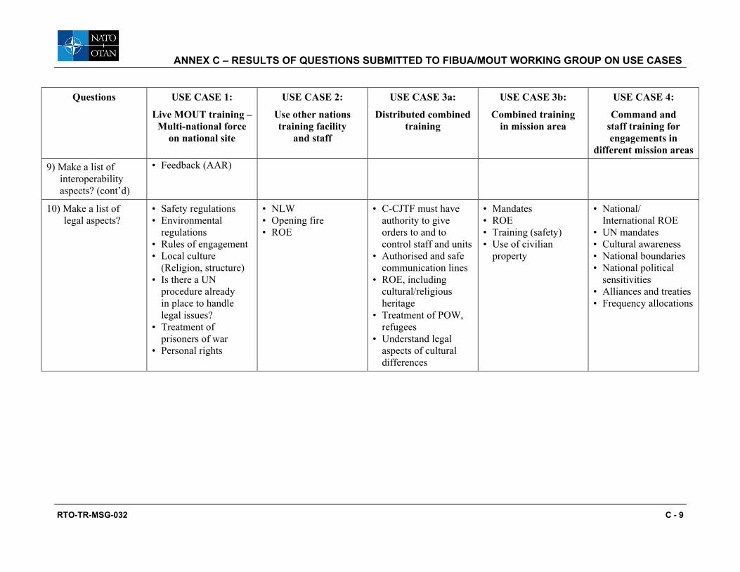
ANNEX C – RESULTS OF QUESTIONS SUBMITTED TO FIBUA/MOUT WORKING GROUP ON USE CASES
RTO-TR-MSG-032 C - 9
Questions USE CASE 1:
Live MOUT training – Multi-national force
on national site
USE CASE 2:
Use other nations training facility
and staff
USE CASE 3a:
Distributed combined training
USE CASE 3b:
Combined training in mission area
USE CASE 4:
Command and staff training for engagements in
different mission areas
9) Make a list of interoperability aspects? (cont’d)
• Feedback (AAR)
10) Make a list of legal aspects?
• Safety regulations • Environmental
regulations • Rules of engagement • Local culture
(Religion, structure) • Is there a UN
procedure already in place to handle legal issues?
• Treatment of prisoners of war
• Personal rights
• NLW • Opening fire • ROE
• C-CJTF must have authority to give orders to and to control staff and units
• Authorised and safe communication lines
• ROE, including cultural/religious heritage
• Treatment of POW, refugees
• Understand legal aspects of cultural differences
• Mandates • ROE • Training (safety) • Use of civilian
property
• National/ International ROE
• UN mandates • Cultural awareness • National boundaries • National political
sensitivities • Alliances and treaties • Frequency allocations

ANNEX C – RESULTS OF QUESTIONS SUBMITTED TO FIBUA/MOUT WORKING GROUP ON USE CASES
C - 10 RTO-TR-MSG-032

RTO-TR-MSG-032 D - 1
Annex D – FIBUA/MOUT REGISTER
The FIBUA/MOUT Website is a restricted website that is accessible by password and is located at www.fibuamoutsite.info. Its purpose is to provide information related to FIBUA/MOUT training sites, best practice (tactics and training), new technology and general news items related to urban training.
Figure D-1 illustrates the MOUT Sites webpage. As clearly stated in the text at the top of the page it relies on member nations to input the necessary detail.
Figure D-1: Screenshot from FIBUA/MOUT Website.

ANNEX D – FIBUA/MOUT REGISTER
D - 2 RTO-TR-MSG-032
Figure D-2: Site Overview Screenshot from FIBUA/MOUT Website.

RTO-TR-MSG-032 E - 1
Annex E – EXAMPLE OF BEST PRACTICE FOR THE OBSERVER CONTROLLER FUNCTION IN SUPPORT
OF INFANTRY BATTALION EXERCISE
E.1 INTRODUCTION
As a result of a Syndicate discussion at a meeting of the FIBUA/MOUT WG they made the following suggestions regarding the functions of an Observer Controller (O/C). They defined the function as having two sub-functions:
• Observer – Observing and taking notes (Monitoring); and
• Controller – Should/can interfere in the conduct of the exercise and supports the conduct of the After Action Review (AAR).
E.2 O/C REQUIREMENTS IN SUPPORT OF AN INFANTRY BATTALION EXERCISE
The following are the O/C requirements for an Infantry battalion exercise suggested as best practice:
• O/C Capabilities – The O/C will require the capability to:
• Monitoring of radio/communication on the unit/sub-unit network; and
• Monitoring of radio/communication on the O/C net.
• Soldier/Two-Man Team (1-2) – 1 x O/C unless training is at a basic level, in this case the task may need additional O/C. Main responsibility will be:
• Monitoring every soldier (by eyes on observation) focussing on basic skills/drills.
• Squad/Section Group (6-10) – 1 or 2 x O/C unless training is at a basic level, in this case the task may need additional O/C. Responsible for monitoring squad/section network, (platoon network) and the O/C network both Blue Forces and Opposing Forces (OPFOR). Key tasks are to:
• Focus on squad/section leadership and Command and Control (C2);
• Focus on use of support weapons and Infantry Fighting Vehicles (IFV);
• Monitoring every soldier/support weapon in squad/section using where available “on-line” portable display type equipment such as Personnel Digital Assistant (PDA) to provide dynamic information (e.g. location, status, images and overlays);
• Be able to switch between graphics/images by clicking icons (soldier/weapon/sensors);
• Be able to activate/deactivate the enemy;
• Be able to activate/deactivate targets/effects; and
• Be able to split up into two O/C (with communications).

ANNEX E – EXAMPLE OF BEST PRACTICE FOR THE OBSERVER CONTROLLER FUNCTION IN SUPPORT OF INFANTRY BATTALION EXERCISE
E - 2 RTO-TR-MSG-032
SL
MG
R2
+
R1
AT1
Cam1
Cam2
Cam3
Cam4STATUS:AT2Light Wounded1 x AT4CS300 x 5,56
AT2
R1
SLSL
MGMG
R2R2
++
R1R1
AT1AT1
Cam1
Cam2
Cam3
Cam4STATUS:AT2Light Wounded1 x AT4CS300 x 5,56
AT2AT2
R1R1
Figure E-1: PDA Type Display.
• Platoon – 1 x O/C to follow Platoon Leader/Commander, 1 x O/C per squad/section (maximum effort). Responsible for monitoring platoon network, (company network) and the O/C network both Blue Forces and Opposing Forces (OPFOR). Key tasks are to:
• Focus on platoon leadership and C2;
• Focus on use of support weapons and IFV;
• Monitoring every squad (soldier), support weapon in platoon using where available “on-line” portable display type equipment such as PDA to provide dynamic information (e.g. location, status, images and overlays);
• Be able to switch between graphics/images by clicking icons (soldier/weapon/sensors);
• Be able to activate/deactivate OPFOR; and
• Be able to activate/deactivate targets/effects.
• Company – 1 x O/C to follow Company Commander, 1 x 2ic, 1 x O/C per platoon (maximum effort) and 1 to 3 x O/C to monitor Support systems (combat support, combat service support). Responsible for monitoring company network, (battalion network) and the O/C network both Blue Forces and Opposing Forces (OPFOR). Need for controlling safety on squad/section (Safety team dependent on scenario). Key tasks are to:
• Focus on company leadership and C2;
• Focus on support weapons and IFV and Tanks);
• Monitoring every platoon (squad), support weapon in company using where available “on-line” portable display type equipment such as PDA to provide dynamic information (e.g. location, status, images and overlays);
• Be able to switch between graphics/images by clicking icons (soldier/weapon/sensors);
• Be able to activate/deactivate the enemy; and
• Be able to activate/deactivate targets/effects.

ANNEX E – EXAMPLE OF BEST PRACTICE FOR THE OBSERVER CONTROLLER FUNCTION IN SUPPORT OF INFANTRY BATTALION EXERCISE
RTO-TR-MSG-032 E - 3
• Battalion – 4 x O/C to follow Battalion Staff, 2 x O/C per company (maximum effort). O/C employment will depend on battalion organisation and exercise scenario. Responsibility for monitoring battalion network, (brigade network) and the O/C network both Blue Forces and Opposing Forces (OPFOR). Need for controlling safety on squad (Safety team dependent on scenario):
• Focus on Battalion leadership and C2;
• Focus on support weapon and battalion level functions;
• Monitoring every company (platoon), support weapons in battalion using where available “on-line” portable display type equipment such as PDA to provide dynamic information (e.g. location, status, images and overlays);
• Be able to switch between graphics/images by clicking icons (soldier/weapon/sensors); and
• Be able to activate/deactivate the enemy.
Situation Center/EXCON
Exercise Staff O/C
O/CSafety
Situation Center/EXCON
Exercise Staff O/C
O/CSafety
Situation Center/EXCON
Exercise Staff O/C
O/CSafety
Figure E-2: Exercise Supporting Staff Structure.

ANNEX E – EXAMPLE OF BEST PRACTICE FOR THE OBSERVER CONTROLLER FUNCTION IN SUPPORT OF INFANTRY BATTALION EXERCISE
E - 4 RTO-TR-MSG-032

RTO-TR-MSG-032 F - 1
Annex F – CAPABILITY REQUIREMENTS MATRIX
Colour Coding of the Requirements G This is a functional requirement relevant to the functional architecture
Y Design constraint
A This requirement is a duplicate, it is covered by one or more other requirements
R This is not a functional requirement relevant to the functional architecture
GENERAL OPERATIONAL CAPABILITIES
1) Provide Linkages to:
G a) Virtual training environment
G b) Constructive training environment
G c) C4I systems
G d) Other live instrumentation systems
2) Support:
G a) Legacy/analogue training units
G b) Modernised/digital training units
G c) Unclassified training events
G d) Classified training events
G
e) Training level from individual soldier up through brigade staff (including multi-national joint and 3 block war)
G f) Current multi-national doctrine and TTPs
3) Support Operational Concept – Continuous Support:
Y a) Up to 24 hours/day
Y b) Up to 300 days/year
Y c) Maximum exercise duration:
Y 1) 1 day
Y 2) 3 days
Y 3) 5 days
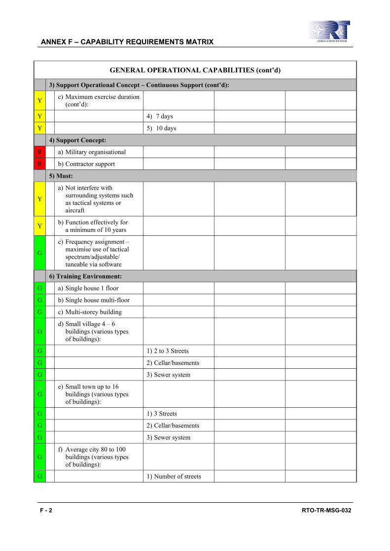
ANNEX F – CAPABILITY REQUIREMENTS MATRIX
F - 2 RTO-TR-MSG-032
GENERAL OPERATIONAL CAPABILITIES (cont’d)
3) Support Operational Concept – Continuous Support (cont’d):
Y c) Maximum exercise duration (cont’d):
Y 4) 7 days
Y 5) 10 days
4) Support Concept:
R a) Military organisational
R b) Contractor support
5) Must:
Y
a) Not interfere with surrounding systems such as tactical systems or aircraft
Y b) Function effectively for a minimum of 10 years
G
c) Frequency assignment – maximise use of tactical spectrum/adjustable/ tuneable via software
6) Training Environment:
G a) Single house 1 floor
G b) Single house multi-floor
G c) Multi-storey building
G d) Small village 4 – 6
buildings (various types of buildings):
G 1) 2 to 3 Streets
G 2) Cellar/basements
G 3) Sewer system
G e) Small town up to 16
buildings (various types of buildings):
G 1) 3 Streets
G 2) Cellar/basements
G 3) Sewer system
G f) Average city 80 to 100
buildings (various types of buildings):
G 1) Number of streets
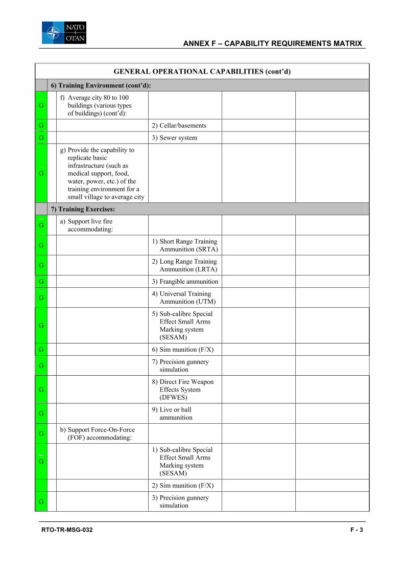
ANNEX F – CAPABILITY REQUIREMENTS MATRIX
RTO-TR-MSG-032 F - 3
GENERAL OPERATIONAL CAPABILITIES (cont’d)
6) Training Environment (cont’d):
G f) Average city 80 to 100
buildings (various types of buildings) (cont’d):
G 2) Cellar/basements
G 3) Sewer system
G
g) Provide the capability to replicate basic infrastructure (such as medical support, food, water, power, etc.) of the training environment for a small village to average city
7) Training Exercises:
G a) Support live fire accommodating:
G 1) Short Range Training Ammunition (SRTA)
G 2) Long Range Training Ammunition (LRTA)
G 3) Frangible ammunition
G 4) Universal Training Ammunition (UTM)
G
5) Sub-calibre Special Effect Small Arms Marking system (SESAM)
G 6) Sim munition (F/X)
G 7) Precision gunnery simulation
G 8) Direct Fire Weapon
Effects System (DFWES)
G 9) Live or ball ammunition
G b) Support Force-On-Force (FOF) accommodating:
G
1) Sub-calibre Special Effect Small Arms Marking system (SESAM)
2) Sim munition (F/X)
G 3) Precision gunnery simulation

ANNEX F – CAPABILITY REQUIREMENTS MATRIX
F - 4 RTO-TR-MSG-032
GENERAL OPERATIONAL CAPABILITIES (cont’d)
7) Training Exercises (cont’d):
G b) Support Force-On-Force
(FOF) accommodating (cont’d):
4) Tactical Engagement Simulation (TES)
G c) Support Force-On-Target (FOT) accommodating:
G
1) Sub-calibre Special Effect Small Arms Marking system (SESAM)
G 2) Sim munition (F/X)
G 3) Precision gunnery simulation
G 4) Tactical Engagement Simulation (TES)
PERFORMANCE CAPABILITIES
1) Exercise Planning:
Y a) Long-range (180+ day out):
Y 1) Selection of missions
Y 2) Determination of tasks
Y 3) Establishment of
training objectives and measures
Y 4) Development of task organisation
Y b) Short-range (90 – 180 day out):
Y 1) Cross-reference of
training events and objectives
Y 2) Identification and
allocation of resources
Y 3) Coordination with support agencies
Y
4) Publication of training guidance and a planning calendar

ANNEX F – CAPABILITY REQUIREMENTS MATRIX
RTO-TR-MSG-032 F - 5
PERFORMANCE CAPABILITIES (cont’d)
1) Exercise Planning (cont’d):
Y c) Near-term (30 – 90 days out):
Y 1) Allocation of resources
Y 2) Publication of schedule
Y 3) Provision of training
execution and evaluation
2) Scenario Development:
G a) Create/modify operational plans
G b) Use/modify archived scenarios
G c) Create custom-designed graphics and symbols
G d) Use/generate digital terrain data
G e) Provide scenarios with the capability to:
R
1) Represent appropriate tactics and behaviours for civilian paramilitary forces, non-combatants, and vehicles
G
2) Provide multi-sided, multi-force combat operations; i.e. more than two-sided, red versus blue, to include Civilians On the Battlefield (COB), guerrilla forces, and other friendly and opposing forces as required for realistic combat operations
R
3) Represent appropriate international, regional, and local situation in the context of population, ethnic, cultural and political factions

ANNEX F – CAPABILITY REQUIREMENTS MATRIX
F - 6 RTO-TR-MSG-032
PERFORMANCE CAPABILITIES (cont’d)
3) System Preparation:
G a) System installation:
G 1) Mount or embed
Tactical Engagement System (TES):
G a) Dismounted personnel
G b) Vehicles
G c) Weapons
G d) Aircraft
G e) Combat boats
Y
2) Install must not require any permanent or irreversible modification to personal equipment or platforms (unless modifications are approved by systems manager)
Y
3) Use vehicle/weapon platform power sources, sensors, etc. (to use existing power sources to reduce additional power sources needed to operate the system)
Y
4) Install on/interface with host prior to unit draw and perform function within 5 minutes of power application
Y
5) Install on/interface with host prior to unit draw and perform function within 25 minutes of power application for aircraft

ANNEX F – CAPABILITY REQUIREMENTS MATRIX
RTO-TR-MSG-032 F - 7
PERFORMANCE CAPABILITIES (cont’d)
3) System Preparation (cont’d):
G a) System installation (cont’d):
Y 6) Mobile and
conformable components:
Y
a) Automatically recognised, control and communicate with system peripherals
Y b) Standardised “quick”
connect/disconnect plug
Y b) Site preparation:
Y 1) Type of facility:
Y a) Fixed site
Y b) Mobile or transportable unit
Y c) Distributed
Y 2) Standardised “quick”
connect/disconnect plug
Y 3) Mission capable:
Y a) Fixed site within 6 hours of notification
Y
b) Mobile or transportable unit within 4 hours of notification
Y
4) Mobile or transportable unit must be configured and tested within 24 hours of arrival at training site
A c) Scenario preparation:
A
1) Capable to develop and use standardised and tailorable scenario to meet training objectives

ANNEX F – CAPABILITY REQUIREMENTS MATRIX
F - 8 RTO-TR-MSG-032
PERFORMANCE CAPABILITIES (cont’d)
3) System Preparation (cont’d):
A c) Scenario preparation (cont’d):
A
2) Provide for exercises control required to support training objectives through:
A a) Target and sensor actuation events
A
b) Battlefield visualisations simulation/ stimulation
A c) Threat simulations
G d) System initialisation:
G
1) Capable to bring to a mission-capable condition to support the exercises
G
2) Be able to initialise all or selected part of the system on command
G 3) Resume initialisation on command
G
4) Set system components and software to unit-specific condition to establish the configuration required to support the exercise
G 5) Enter unit-specific
initialisation data to support the exercise
G
e) Exercise rehearsal – verify functions before full initialisation (self-test subcomponents)
G f) Readiness verification –
verify readiness of system to support:
G
1) Perform pre-exercise checks/test to report ready status of system components

ANNEX F – CAPABILITY REQUIREMENTS MATRIX
RTO-TR-MSG-032 F - 9
PERFORMANCE CAPABILITIES (cont’d)
3) System Preparation (cont’d):
G f) Readiness verification –
verify readiness of system to support (cont’d):
G 2) Generate listing of
initialisation data and results
4) Exercise Execution:
G a) Capable of:
G 1) Collect, manage, and analyze voice data
G 2) Collect, manage and analyze video data
G 3) Collect, manage,
and analyze digital exercise data
R 4) Live role playing
G 5) Communications
with field components
G
6) Communications with trainers (Observers/ Controllers)
G 7) Communications
with staff components
G
8) Monitor status of the total system, including distributed components (e.g. other sites)
G b) Combat area simulation:
G
1) Provide doctrinally accurate representation of terrain:
G a) Leveraging synthetic environment
G b) Warfighting system
battlefield visualisation
G c) Tactical system digital terrain

ANNEX F – CAPABILITY REQUIREMENTS MATRIX
F - 10 RTO-TR-MSG-032
PERFORMANCE CAPABILITIES (cont’d)
4) Exercise Execution (cont’d):
G c) Weapon simulation:
G
1) Simulate the engagement and physical/structure damage and casualty producing effects of:
G a) Direct weapons and munitions
G b) Indirect weapons and munitions
G c) Air delivered
weapons and munitions
G d) Non-lethal weapons and munitions
G e) Hand grenades
G f) Thermo baric
G
2) Simulate the effects of weapon engagement data causing visual collateral damage without any permanent damage to the structure
G d) Environment hazards simulation:
G
1) Simulate the physical/structure damage and casualty producing effects of:
G a) Environmental
G b) Industrial
G
2) Simulate the effects of environmental and/or industrial without any permanent damage to the structure or inducing health factors on role players or soldiers

ANNEX F – CAPABILITY REQUIREMENTS MATRIX
RTO-TR-MSG-032 F - 11
PERFORMANCE CAPABILITIES (cont’d)
4) Exercise Execution (cont’d):
G e) Target control:
G
1) Provide or enable the capability to synchronise target, sensor or stimulator presentation functions for:
G a) Live fire exercises
G b) Force-On-Target exercises
G c) Force-On-Force (FOF) exercises
G 2) Allow to interface
with existing or future targets system
G 3) Allow the operator the ability to:
G
a) Run complete scenario automatically by time control
G
b) Run complete scenario automatically by event control
G c) Run scenario on command
G d) Start scenario from
any step in the scenario
G e) Stop the scenario on
command at any step in the scenario
G f) Restart the scenario
at any step in the scenario
G g) Modify the scenario
G h) Change from on
scenario to another scenario
G 4) Enable targets or stimulator randomly
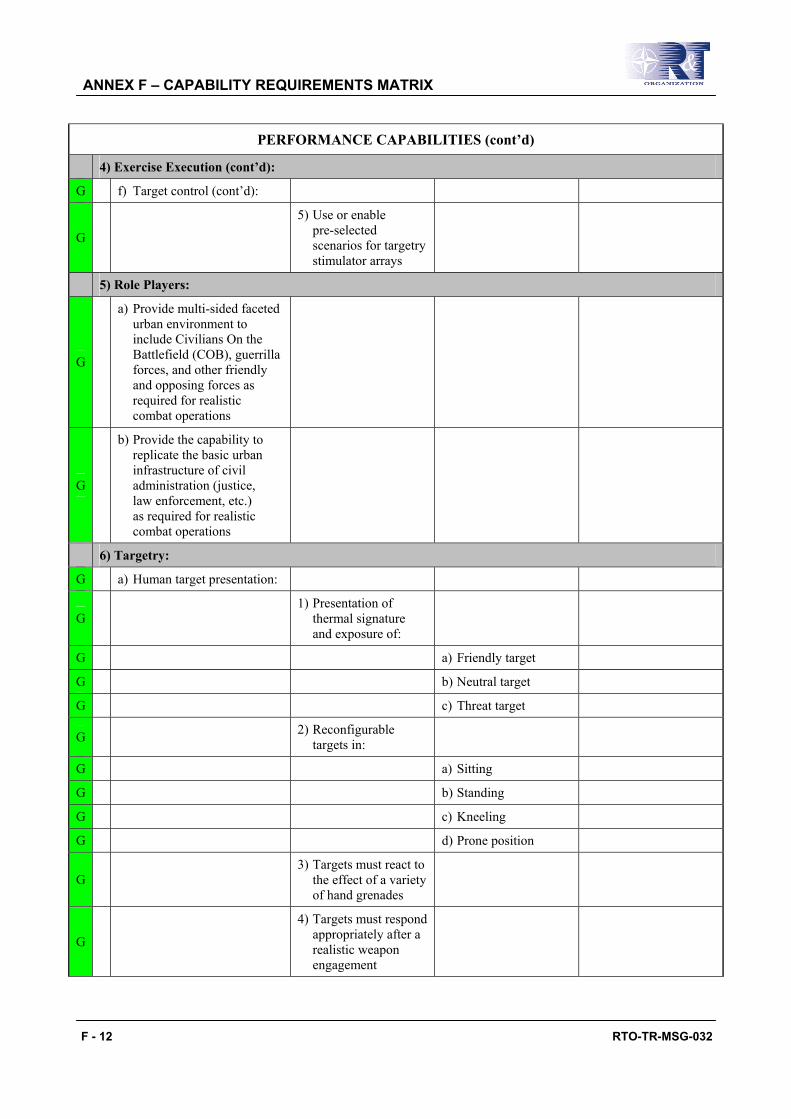
ANNEX F – CAPABILITY REQUIREMENTS MATRIX
F - 12 RTO-TR-MSG-032
PERFORMANCE CAPABILITIES (cont’d)
4) Exercise Execution (cont’d):
G f) Target control (cont’d):
G
5) Use or enable pre-selected scenarios for targetry stimulator arrays
5) Role Players:
G
a) Provide multi-sided faceted urban environment to include Civilians On the Battlefield (COB), guerrilla forces, and other friendly and opposing forces as required for realistic combat operations
G
b) Provide the capability to replicate the basic urban infrastructure of civil administration (justice, law enforcement, etc.) as required for realistic combat operations
6) Targetry:
G a) Human target presentation:
G 1) Presentation of
thermal signature and exposure of:
G a) Friendly target
G b) Neutral target
G c) Threat target
G 2) Reconfigurable targets in:
G a) Sitting
G b) Standing
G c) Kneeling
G d) Prone position
G 3) Targets must react to
the effect of a variety of hand grenades
G
4) Targets must respond appropriately after a realistic weapon engagement

ANNEX F – CAPABILITY REQUIREMENTS MATRIX
RTO-TR-MSG-032 F - 13
PERFORMANCE CAPABILITIES (cont’d)
6) Targetry (cont’d):
G a) Human target presentation (cont’d):
G
5) Shoot back target signature/simulate flash, bang and smoke of threat weapon engagement
G
6) Will have the capability to adjust to response from 1 – 10 seconds
G
7) Provide two way audio to replicate normal human interaction
G 8) Provide animation
to replicate normal human interaction
Y 9) Provide a thermal signature
Y 10) Must be able to
react to all types of training exercises
G
11) Will stimulate battlefield combat identification capabilities at extended ranges
G b) Vehicle target presentation:
G 1) Wheeled vehicle targetry must be:
G a) 2 dimensional
G b) 3 dimensional
G 2) Provide a thermal signature
G
3) Must provide audio and visual feedback after a realistic weapon engagement
G
4) Must be programmable and operate by remote control/self propel

ANNEX F – CAPABILITY REQUIREMENTS MATRIX
F - 14 RTO-TR-MSG-032
PERFORMANCE CAPABILITIES (cont’d)
6) Targetry (cont’d):
G b) Vehicle target presentation (cont’d):
G 5) Must respond to
hit placement recognition
G
6) Shoot back target signature/simulate flash, bang, and smoke of threat weapon engagement
G
7) Provide two-way audio to replicate normal vehicle interaction
G 8) Provide animation
to replicate normal vehicle interaction
Y 9) Provide a thermal signature
Y 10) Must be able to
react to all types of training exercises
G
11) Will stimulate battlefield combat identification capabilities at extended ranges
7) Data Collection:
G a) Capable of:
G 1) Collect, verify,
record, transmit and receive voice:
G a) Inside buildings; at minimum:
G i) Stairwell
G ii) Room
G iii) Hallway
G iv) Tunnel/sewer system
G v) Tunnel entry/access
areas to include basement
G b) Rooftops
G c) Outside buildings

ANNEX F – CAPABILITY REQUIREMENTS MATRIX
RTO-TR-MSG-032 F - 15
PERFORMANCE CAPABILITIES (cont’d)
7) Data Collection (cont’d): G a) Capable of (cont’d):
G 2) Collect, verify, and record video:
G a) Inside buildings; at minimum:
G i) Stairwell G ii) Room G iii) Hallway G iv) Tunnel/sewer system
G
v) Tunnel entry/access areas to include basement
G b) Primary approach into: G i) Rooftops G ii) Outside buildings
G 3) Collect, verify, and
record digital force-on-force exercise data
4) Collect, verify, and
record live fire exercise data
G 5) Interface with exercise systems
G 6) Interface with external systems:
G a) Constructive systems G b) Virtual systems
G c) Other live training systems
R 7) Interface with devices
link to and supporting the exercise
G 8) Data must be collected by:
G
a) Force (combat, combat support and combat service support, special operations forces (SOF), etc.):
G
i) Battle status by echelon
G
ii) Troop status by echelon

ANNEX F – CAPABILITY REQUIREMENTS MATRIX
F - 16 RTO-TR-MSG-032
PERFORMANCE CAPABILITIES (cont’d)
7) Data Collection (cont’d):
G a) Capable of (cont’d):
G 8) Data must be collected by (cont’d):
G b) Warfighting platform
(weapon type and unique ID)
G c) Echelon (team,
squad, platoon, and company team)
G d) Army universal task
list and battlefield operation system
G
9) Collect and interpret/ process digital training performance data to minimise training staff
G 10) Time tag in near real-time:
G a) Position location
G b) System status
G c) Voice/video
G d) Tactical Engagement
Simulation (TES) data for:
G i) Exercise participants
G ii) Vehicles
G iii) Aircraft
G
iv) Selected support personnel, vehicles, aircraft within maneuver area and surrounding airspace
G 11) Store all essential exercise data
G
12) Provide position location (X,Y,Z axis) down to individual instrumented level:
G a) Indoor
G b) Outdoor

ANNEX F – CAPABILITY REQUIREMENTS MATRIX
RTO-TR-MSG-032 F - 17
PERFORMANCE CAPABILITIES (cont’d)
7) Data Collection (cont’d):
G a) Capable of (cont’d):
R
13) Record and display position location for fixed and rotary wing (transport, scout, and attack) aircraft operating in the urban training maneuver area
Y 14) All collection devices must:
Y a) Be unobtrusive to the training unit
Y
b) Operate and withstand all type of environmental conditions
Y c) Operate and
withstand all type of scenarios:
Y
i) Short Range Training Ammunition (SRTA)
Y
ii) Long Range Training Ammunition (LRTA)
Y
iii) Universal Training Ammunition (UTM)
Y
iv) Sub-calibre Special Effect Small Arms Marking system (SESAM)
Y
v) Precision gunnery simulation
Y
vi) Tactical Engagement Simulation (TES)
Y
vii) Ball ammunition /service ammunition
Y
d) Operate in artificial conditions (i.e. obscurants (smoke))
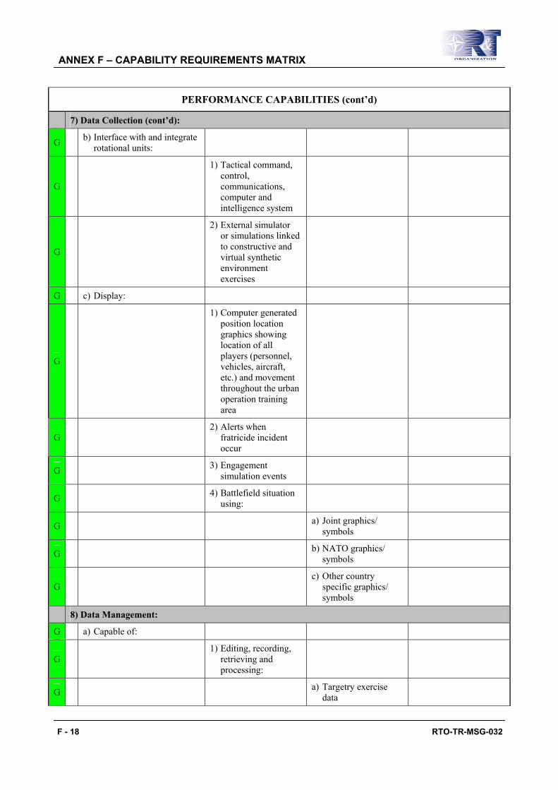
ANNEX F – CAPABILITY REQUIREMENTS MATRIX
F - 18 RTO-TR-MSG-032
PERFORMANCE CAPABILITIES (cont’d)
7) Data Collection (cont’d):
G b) Interface with and integrate rotational units:
G
1) Tactical command, control, communications, computer and intelligence system
G
2) External simulator or simulations linked to constructive and virtual synthetic environment exercises
G c) Display:
G
1) Computer generated position location graphics showing location of all players (personnel, vehicles, aircraft, etc.) and movement throughout the urban operation training area
G 2) Alerts when
fratricide incident occur
G 3) Engagement simulation events
G 4) Battlefield situation using:
G a) Joint graphics/ symbols
G b) NATO graphics/ symbols
G c) Other country
specific graphics/ symbols
8) Data Management:
G a) Capable of:
G 1) Editing, recording,
retrieving and processing:
G a) Targetry exercise data

ANNEX F – CAPABILITY REQUIREMENTS MATRIX
RTO-TR-MSG-032 F - 19
PERFORMANCE CAPABILITIES (cont’d)
8) Data Management (cont’d):
G a) Capable of (cont’d):
G 1) Editing, recording,
retrieving and processing (cont’d):
G b) Tactical engagement
simulation exercise data
G c) Voice exercise data
G d) Video exercise data
G e) Digital exercise data
G 2) Manipulating data to
display battle events at workstations with:
G a) Position location
G b) Date/time synchronisation
G c) Textual and graphical data
G 3) Organise, sort,
collate, distribute and display:
G a) Targetry exercise data
G b) Tactical engagement
simulation exercise data
G c) Voice exercise data
G d) Video exercise data
G e) Digital exercise data
G 4) Retrieve and process
casualty/damage assess for:
G a) Direct weapons
engagement simulations
G b) Area weapons
engagement simulations
G
c) Nuclear, biological, and chemical engagement simulations

ANNEX F – CAPABILITY REQUIREMENTS MATRIX
F - 20 RTO-TR-MSG-032
PERFORMANCE CAPABILITIES (cont’d)
8) Data Management (cont’d): G a) Capable of (cont’d):
G 4) Retrieve and process
casualty/damage assess for (cont’d):
G
d) Electronic warfare engagement simulations (including jamming)
G e) Information warfare
G
5) Selectively retrieving, process, distributing and displaying exercise data at:
G a) Group workstations
G b) Individual workstations
G c) In central analysis facilities
G d) In remote analysis facilities
G
6) Entering, recording, retrieving, editing and displaying textual and graphical data at workstations
G
7) Determine movement and speed of movement of exercise players
G
8) Organise digital training performance data in data structures to prepare to build the after action review
G
9) Retrieve and process digital training performance data to replay exercise history to support performance analysis and feedback
G
10) Provide capability to prepare, scan, and edit graphic control measures in accordance with current operational symbology and graphics

ANNEX F – CAPABILITY REQUIREMENTS MATRIX
RTO-TR-MSG-032 F - 21
PERFORMANCE CAPABILITIES (cont’d) 8) Data Management (cont’d):
G a) Capable of (cont’d):
G
11) Provide capability to translate between different languages when handling tactical and training data from multi-national participants/systems
9) Exercise Control:
G a) Capable of:
G
1) Provide two-way non-tactical communications between analysts and controller in the central or remote analysis facilities
G
2) Provide two-way tactical communications between exercise controller in the central and remote analysis facilities and the unit in the field to assist in role playing and controlling the exercise
G
3) Provide two-way non-tactical communications between analysts, scenario controller and role players in the central or remote areas
G
4) Monitor voice, video, RF and digital representation replicating the battlefield and tactical engagement simulations
G
5) Generate and transmit control commands from workstation to warfighting platforms/embedded training system and Tactical Engagement Simulation (TES) in the field

ANNEX F – CAPABILITY REQUIREMENTS MATRIX
F - 22 RTO-TR-MSG-032
PERFORMANCE CAPABILITIES (cont’d)
9) Exercise Control (cont’d):
G a) Capable of (cont’d):
G
6) Exchange exercise data with external simulations and system to control the conduct of the exercise
G
7) Must generate audio/ voice alerts when pre-defined significant safety or controller events occur
A
8) Provide, on demand, current tactical status of fully instrumented players in exercise area
A
9) Monitor and display instrumented direct and indirect fire engagement battlefield damage and assessment
G
10) Record control commands from the central or remote analysis facilities and controller devices in the field for later replay and review
G
11) Provide the capability to control and continuously monitor the operational status of all discrete digital and analogue devices
G 12) Provide the
capability from a central point:
G a) Inside buildings; at minimum:
G i) Alert system (safety)
G ii) Locking doors

ANNEX F – CAPABILITY REQUIREMENTS MATRIX
RTO-TR-MSG-032 F - 23
PERFORMANCE CAPABILITIES (cont’d)
9) Exercise Control (cont’d):
G
a) Capable of (cont’d): 12) Provide the capability from a central point (cont’d):
G a) Inside buildings; at minimum (cont’d):
G iii) Lighting
G iv) Battlefield effects
G v) Targets
G vi) Audio
G vii) Video
G b) Outside buildings; at minimum:
G i) Alert system (safety)
G ii) Lighting
G iii) Battlefield effects
G iv) Targets
G v) Audio
G vi) Video
G
13) Provide the capability to administratively kill or resurrect any instrumented player within training area
A
14) Exchange digital data to control the conduct of the exercise with:
A a) Live simulations
A b) Virtual simulations
A c) Constructive simulations
G b) Generate and display:
G 1) Exercise report and summaries
G
2) Information to perform near real-time casualty and damage assessments for area weapons engagement simulations

ANNEX F – CAPABILITY REQUIREMENTS MATRIX
F - 24 RTO-TR-MSG-032
PERFORMANCE CAPABILITIES (cont’d)
9) Exercise Control (cont’d):
G b) Generate and display (cont’d):
G
3) Alarms and alerts when operating limits are not maintained
G 4) Weather data
G c) Be able to control up to
multiple different exercises simultaneously
10) Data Analysis:
G a) Capable of:
G 1) Query data
G 2) Correlate and analyze:
G a) Targerty exercise data
G b) Tactical Engagement
Simulation (TES) exercise data
G c) Voice exercise data
G d) Video exercise data
G e) Digital exercise data
G 3) Selectively retrieve
and display exercise data
G 4) Store, edit, and replay voice and video data
G 5) Export data
G 6) Replay exercise history
G b) Archive data
11) Training Feedback:
G a) Preparation:
G 1) Provide the ability to mix
G a) Voice recordings
G b) Video recordings
G c) Graphics
G d) Digital data
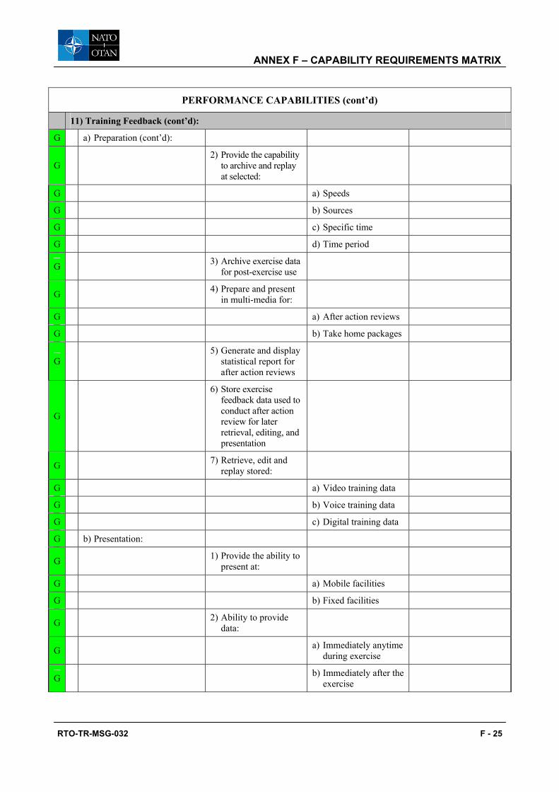
ANNEX F – CAPABILITY REQUIREMENTS MATRIX
RTO-TR-MSG-032 F - 25
PERFORMANCE CAPABILITIES (cont’d)
11) Training Feedback (cont’d):
G a) Preparation (cont’d):
G 2) Provide the capability
to archive and replay at selected:
G a) Speeds
G b) Sources
G c) Specific time
G d) Time period
G 3) Archive exercise data for post-exercise use
G 4) Prepare and present in multi-media for:
G a) After action reviews
G b) Take home packages
G 5) Generate and display
statistical report for after action reviews
G
6) Store exercise feedback data used to conduct after action review for later retrieval, editing, and presentation
G 7) Retrieve, edit and replay stored:
G a) Video training data
G b) Voice training data
G c) Digital training data
G b) Presentation:
G 1) Provide the ability to present at:
G a) Mobile facilities
G b) Fixed facilities
G 2) Ability to provide data:
G a) Immediately anytime during exercise
G b) Immediately after the exercise

ANNEX F – CAPABILITY REQUIREMENTS MATRIX
F - 26 RTO-TR-MSG-032
PERFORMANCE CAPABILITIES (cont’d)
11) Training Feedback (cont’d):
G b) Presentation (cont’d):
G 2) Ability to provide data (cont’d):
G c) After change of mission + 2 hours
G d) After change of mission + 4 hours
G e) After change of mission + 6 hours
G
3) Capture the discussion and points/lesson learned generated during the conduct of the after action review
G 4) Provide the delivery of the presentation in:
G a) Hard copy
G b) Removable electronic media
G c) Take home package:
G 1) Provide the delivery in:
G a) Hard copy
G b) Removable electronic media
G d) Archive:
G 1) Transfer to removable media:
G a) Video training data
G b) Voice training data
G c) Digital training data
G d) Exercise history data
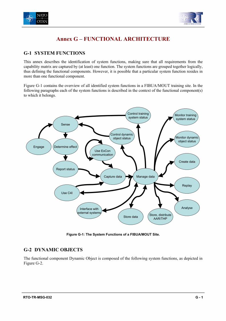
RTO-TR-MSG-032 G - 1
Annex G – FUNCTIONAL ARCHITECTURE
G-1 SYSTEM FUNCTIONS
This annex describes the identification of system functions, making sure that all requirements from the capability matrix are captured by (at least) one function. The system functions are grouped together logically, thus defining the functional components. However, it is possible that a particular system function resides in more than one functional component.
Figure G-1 contains the overview of all identified system functions in a FIBUA/MOUT training site. In the following paragraphs each of the system functions is described in the context of the functional component(s) to which it belongs.
Manage data
Control trainingsystem status
Engage
Sense
Determine effect
Report status
Control dynamicobject status
Use ExConcommunication
Capture data
Use C4I
Interface withexternal systems
Store data
Monitor dynamicobject status
Monitor trainingsystem status
Create data
Replay
Analyse
Store, distributeAAR/THP
Figure G-1: The System Functions of a FIBUA/MOUT Site.
G-2 DYNAMIC OBJECTS
The functional component Dynamic Object is composed of the following system functions, as depicted in Figure G-2.

ANNEX G – FUNCTIONAL ARCHITECTURE
G - 2 RTO-TR-MSG-032
Manage data
Control trainingsystem status
Engage
Sense
Determine effect
Report status
Control dynamicobject status
Use ExConcommunication
Capture data
Use C4I
Interface withexternal systems
Store data
Monitor dynamicobject status
Monitor trainingsystem status
Create data
Replay
Analyse
Store, distributeAAR/THP
Dynamic Object
Figure G-2: The System Functions of a Dynamic Object.
Engage The capability to actively interact with other dynamic objects (e.g. for a rifle: firing a projectile, for a hand grenade: explode).
Sense The capability to sense an event concerning the dynamic object. This could be that the dynamic object is being engaged (e.g. being hit) or that the dynamic object performs an action (“self-sense”, e.g. fire a weapon, changing location as can be sensed by GPS). Also, the dynamic object can receive a direct command to change its status.
Determine Effect The capability to change the status of the dynamic object, depending on the characteristics of the dynamic object and the characteristics of the triggering event (e.g. for a player: get injured, for a target: drop down). This capability resides locally in each dynamic object.
Report Status The capability to represent the current (change of) status of the dynamic object. Depending on the implementation, it can be activated in regular time steps or when a relevant change has occurred. This capability includes the communication of its status within the training system (e.g. location, operational status) and the physical representation in terms of several different effects (visual, audio, smell, taste, movement, electromagnetic, etc.).
Use C4I The capability to monitor and interact with C4I systems (e.g. those issued to personnel, those embedded within weapon systems).

ANNEX G – FUNCTIONAL ARCHITECTURE
RTO-TR-MSG-032 G - 3
G-3 EXERCISE CONTROL
The functional component Exercise Control (EXCON) is composed of the following system functions, as depicted in Figure G-3.
Exercise Control
Manage data
Control trainingsystem status
Engage
Sense
Determine effect
Report status
Control dynamicobject status
Use ExConcommunication
Capture data
Use C4I
Interface withexternal systems
Store data
Monitor dynamicobject status
Monitor trainingsystem status
Create data
Replay
Analyse
Store, distributeAAR/THP
Figure G-3: Exercise Control.
Create Data The capability to define exercises, e.g. defining the dynamic objects that will take part, their initial status, planned events (e.g. artillery strike).
Capture Data The capability to receive information from training system components and C4I systems.
Store Data The capability to retain data.
Replay The capability to review the events that have occurred and have been stored during a certain exercise (e.g. actions of dynamic objects, communications, C4I information).
Analyse The capability to evaluate the results of an exercise.
Store and Distribute AAR/THP
The capability to create, save and issue evaluation material and THP.
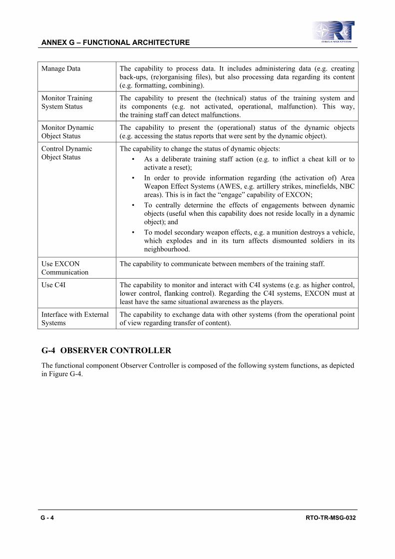
ANNEX G – FUNCTIONAL ARCHITECTURE
G - 4 RTO-TR-MSG-032
Manage Data The capability to process data. It includes administering data (e.g. creating back-ups, (re)organising files), but also processing data regarding its content (e.g. formatting, combining).
Monitor Training System Status
The capability to present the (technical) status of the training system and its components (e.g. not activated, operational, malfunction). This way, the training staff can detect malfunctions.
Monitor Dynamic Object Status
The capability to present the (operational) status of the dynamic objects (e.g. accessing the status reports that were sent by the dynamic object).
Control Dynamic Object Status
The capability to change the status of dynamic objects: • As a deliberate training staff action (e.g. to inflict a cheat kill or to
activate a reset); • In order to provide information regarding (the activation of) Area
Weapon Effect Systems (AWES, e.g. artillery strikes, minefields, NBC areas). This is in fact the “engage” capability of EXCON;
• To centrally determine the effects of engagements between dynamic objects (useful when this capability does not reside locally in a dynamic object); and
• To model secondary weapon effects, e.g. a munition destroys a vehicle, which explodes and in its turn affects dismounted soldiers in its neighbourhood.
Use EXCON Communication
The capability to communicate between members of the training staff.
Use C4I The capability to monitor and interact with C4I systems (e.g. as higher control, lower control, flanking control). Regarding the C4I systems, EXCON must at least have the same situational awareness as the players.
Interface with External Systems
The capability to exchange data with other systems (from the operational point of view regarding transfer of content).
G-4 OBSERVER CONTROLLER
The functional component Observer Controller is composed of the following system functions, as depicted in Figure G-4.

ANNEX G – FUNCTIONAL ARCHITECTURE
RTO-TR-MSG-032 G - 5
Observer / Controller
Manage data
Control trainingsystem status
Engage
Sense
Determine effect
Report status
Control dynamicobject status
Use ExConcommunication
Capture data
Use C4I
Interface withexternal systems
Store data
Monitor dynamicobject status
Monitor trainingsystem status
Create data
Replay
Analyse
Store, distributeAAR/THP
Figure G-4: Observer Controller.
Sense Although O/Cs are not players, they operate within the training environment and need to have information about for example artillery zones, minefields, when they are engaged, etc.
Determine Effect Many of the sensed events will result in reports to the O/C, not into the change of its status (e.g. an O/C should be notified when he enters a minefield, but he will not be injured by that minefield).
Report Status For example in order to represent the position of an O/C in the training staff applications.
Use C4I The capability to monitor and interact with C4I systems. Regarding the C4I systems, an O/C must at least have the same situational awareness as the players.
Capture Data The capability to receive information from training system components and C4I systems.
Monitor Dynamic Object Status
Like the central training staff, an O/C must be able to monitor the (operational) status of the dynamic objects.
Control Dynamic Object Status
And to change the status of a dynamic object.
Use EXCON Communication

ANNEX G – FUNCTIONAL ARCHITECTURE
G - 6 RTO-TR-MSG-032
G-5 AFTER ACTION REVIEW
The functional component After Action Review is composed of the following system functions, as depicted in Figure G-5.
After Action Review
Manage data
Control trainingsystem status
Engage
Sense
Determine effect
Report status
Control dynamicobject status
Use ExConcommunication
Capture data
Use C4I
Interface withexternal systems
Store data
Monitor dynamicobject status
Monitor trainingsystem status
Create data
Replay
Analyse
Store, distributeAAR/THP
Figure G-5: After Action Review.
As can be deduced from the functional breakdown, AAR is functionally a full sub-component of EXCON, but is was considered very important to make this group of functions visible at the highest level as a functional component of a FIBUA/MOUT system.
G-6 SYSTEM CONTROL
The functional component System Control is composed of the following system functions, as depicted in Figure G-6.

ANNEX G – FUNCTIONAL ARCHITECTURE
RTO-TR-MSG-032 G - 7
System Control
Manage data
Control trainingsystem status
Engage
Sense
Determine effect
Report status
Control dynamicobject status
Use ExConcommunication
Capture data
Use C4I
Interface withexternal systems
Store data
Monitor dynamicobject status
Monitor trainingsystem status
Create data
Replay
Analyse
Store, distributeAAR/THP
Figure G-6: System Control.
Capture Data
Monitor Training System Status
The capability to present the (technical) status of the training system and its components (e.g. not activated, operational, malfunction).
Control Training System Status
The capability to change the (technical) status of the training system or its components. This concerns the system configuration only (e.g. start up, shut down).
Use EXCON Communication
The capability to communicate on the EXCON communication network (e.g. exchange information between system maintenance and the training staff).
Monitor Dynamic Object Status
The capability to present the (operational) status of the dynamic objects (e.g. in order to check the (technical) operational status).
Control Dynamic Object Status
The capability to change the (operational) status of the dynamic objects. This concerns the operational configuration only (e.g. to change set the damage status).
Manage Data Store Data
Interface with External Systems
The capability to exchange data with other systems (from the technical point of view to establish data transfer).

ANNEX G – FUNCTIONAL ARCHITECTURE
G - 8 RTO-TR-MSG-032
G-7 FACILITY CONTROL
The functional component Facility Control is composed of the following system functions, as depicted in Figure G-7.
Facility Control
Manage data
Control trainingsystem status
Engage
Sense
Determine effect
Report status
Control dynamicobject status
Use ExConcommunication
Capture data
Use C4I
Interface withexternal systems
Store data
Monitor dynamicobject status
Monitor trainingsystem status
Create data
Replay
Analyse
Store, distributeAAR/THP
Figure G-7: Facility Control.
Create Data The capability to create a representation of the training environment, e.g. for use as maps and 3D databases.
Store Data
Manage Data

RTO-TR-MSG-032 H - 1
Annex H – INTERFACES
This annex describes in more detail the internal and external interfaces as defined in the functional architecture.
Figure H-1: Interfaces in the Functional Architecture.
ID From To Description
E1 Engage Sense Provides the characteristics of an engagement of a dynamic object.
Sense Determine effect Provides the characteristics of an engagement in order to determine the effects of that engagement.
Determine effect Report status Provides the (change of) operational status of a dynamic object.
E4 Report status Capture data Provides the current status of a dynamic object, both operational status and technical status.
E2 Control training system status
Sense Provides the (change of) technical status of a dynamic object.
E3 Control dynamic object status
Sense Provides the (change of) operational status of a dynamic object.

ANNEX H – INTERFACES
H - 2 RTO-TR-MSG-032
ID From To Description
Use EXCON communication
Capture data Provides data on the EXCON communication network that has to be logged.
E5 Use EXCON communication
Use EXCON communication
Provides to communication between EXCON members of different training systems.
E6 Use C4I Capture data Provides C4I data to the training system (e.g. to be used for AAR, to distribute to EXCON applications).
Capture data Manage data Provides real-time data that has to be processed and/or stored.
Manage data Monitor dynamic object status
Provides data to monitor the operational status of dynamic objects.
Manage data Monitor training system status
Provides data to monitor the technical status of the training system components.
Manage data Control dynamic object status
Provides data to set the operational status of dynamic objects.
Manage data Control training system status
Provides data to set the technical status of training system components.
Manage data Store data Provides processed data to be stored.
Store data Manage data Provides stored data to be (re)processed.
Manage data Create data Provides information about the resources and capabilities of the training system in order to create a scenario.
Create data Manage data Provides scenario data to be stored. It includes initialisation data for all systems involved (e.g. training system, C4I systems).
Manage data Replay Provides data to replay a recorded exercise.
Manage data Analyse Provides data to evaluate.
Manage data Store and distribute AAR/THP
Provides data to create/modify AAR/THP.
Store and distribute AAR/THP
Manage data Provides AAR/THP data to be stored.
E7 Manage data Use C4I Provides data from the training system to C4I systems.
E8 Interface with external systems
Manage data Provides external system data to the training system.
E8 Manage data Interface with external systems
Provides training system data to external systems.

RTO-TR-MSG-032 I - 1
Annex I – EXTERNAL INTERFACES
Below are the basic assumptions concerning the information needed in the different reporting events. Appendices I1 and I2 provide a more detailed analysis of Firing and Target Data.
Object Report Types
Must Know Data Inherent in Must Know Data Might Know Data
Firing Report Shooter platform ID Type (vehicle, person, aircraft) Target platform type
Call-sign
Affiliation (red force, blue force, civilian, etc.)
Target platform affiliation
Assignment (leader squad 1, supply vehicle, etc.)
Target platform assignment
Shooter platform
location x, y, z Target platform location
Weapon ID Type Predicted point of impact
on target Aim point Location
Orientation
Angle
Charge
External conditions (wind, etc.)
Weapon conditions (barrel temperature, etc.)
Type of detonation Impact
Proximity
Time Munition Type of delivery (direct, indirect)
Type of effect (explosive, smoke, biological, etc.)
Duration of effect (immediate, temporary, lingering, etc.)
Hit Status Report Target platform ID Type (vehicle, person, aircraft) Shooter platform type
Call-sign
Affiliation (red force, blue force, civilian, etc.)
Shooter platform affiliation

ANNEX I – EXTERNAL INTERFACES
I - 2 RTO-TR-MSG-032
Object Report Types
Must Know Data Inherent in Must Know Data Might Know Data
Hit Status Report (cont’d)
Target platform ID (cont’d)
Assignment (leader squad 1, supply vehicle, etc.)
Shooter platform assignment
Target platform
status Health (dead, wounded, mobility kill, etc.)
Shooter platform status
Resources (weapons available, rounds remaining, etc.)
Target platform
location x, y, z
Damage sustained
(total kill, tracks destroyed, etc.)
Point of impact on platform (arm, vehicle track, etc.)
Weapon type
Ammunition type
Angle of hit
Force of effect at target location
Self-protection levels
Vulnerability to munition Shooter platform ID Weapon ID Ammunition ID Fire Status Report Shooter platform ID Type (vehicle, person, aircraft)
Call-sign
Affiliation (red force, blue force, civilian, etc.)
Assignment (leader squad 1, supply vehicle, etc.)
Shooter platform
status Health (dead, wounded, mobility kill, etc.)
Resources (weapons available, rounds remaining, etc.)
Shooter platform
location x, y, z

ANNEX I – EXTERNAL INTERFACES
RTO-TR-MSG-032 I - 3
Object Report Types
Must Know Data Inherent in Must Know Data Might Know Data
Fire Status Report (cont’d)
Weapon ID Type
Aim point Location
Orientation
Angle
Charge
External conditions (wind, etc.)
Weapon conditions (barrel temperature, etc.)
Type of detonation Impact
Proximity
Time Munition Type of delivery (direct, indirect)
Type of effect (explosive, smoke, biological, etc.)
Duration of effect (immediate, temporary, lingering, etc.)
Status Report Platform ID Type (vehicle, person, aircraft)
Call-sign
Affiliation (red force, blue force, civilian, etc.)
Assignment (leader squad 1, supply vehicle, etc.)
Platform status Health (dead, wounded, mobility kill,
etc.)
Resources (weapons available, rounds remaining, etc.)

ANNEX I – EXTERNAL INTERFACES
I - 4 RTO-TR-MSG-032
Appendix I1: FIRING DATA
INTRA INTER Internal External
Object Name
Trigger Event
Trigger Event Data
Status Change Visual Effect Acoustic Effect Physical Effect
Visual Effect Acoustic Effect
Physical Effect
Outgoing Event
Outgoing Event Data
Outgoing Event
Recipient
Shooter Fire Main Armament Fired, Secondary Armament Fired, Co-axial weapon Fired
Reduced Ammo, set Weapon Parameters, e.g. barrel temperature, Initiate temporal delays, Set wear and tear parameters
White smoke, temporary, to obscure vision, confirm shot, Cuing information injected into site, for example tracer, to show shooter flight path
Explosive sound, temporary, to impose stress on crew and to increase crew’s situational awareness of crew
Impose firing rate constraints
Smoke, temporary, to indicate position, distance and direction, muzzle fire flash
Loud explosion, temporary, used to reveal position and direction
Firing Report
Shooter Platform ID, Shooter Platform Status, Shooter Platform Location, Weapon ID, Aim Point, Type of Detonation, Munitions
Dynamic Object
Shooter Fire Status Report
Shooter Platform ID, Shooter Platform Status, Shooter Platform Location, Weapon ID, Aim Point, Type of Detonation, Munitions, Observed target for scenario representation
EXCON

ANNEX I – EXTERNAL INTERFACES
RTO-TR-MSG-032 I - 5
INTRA INTER Internal External
Object Name
Trigger Event
Trigger Event Data
Status Change Visual Effect Acoustic Effect Physical Effect
Visual Effect Acoustic Effect
Physical Effect
Outgoing Event
Outgoing Event Data
Outgoing Event
Recipient
Shooter Deploy/ Fire
Type of self-defence, start time, duration, smoke signature
Reduced assets Popping sound to indication protection is launched awareness of crew
Not required White smoke, temporary, to obscure vision Fire Status Report
Shooter Platform ID, Shooter Platform Status, Shooter Platform Location, Weapon ID, Aim Point, Type of Detonation, Munitions, Observed target for scenario representation
EXCON
Shooter Fire Small arms fired, hand grenade, AT weapon, NL weapon, machine gun
Reduced Ammo, set Weapon Parameters, e.g. barrel temperature, Initiate temporal delays, Set wear and tear parameters
Cueing information injected into field of view for example tracer, to show shooter flight path
Impose firing rate constraints
White smoke, temporary, to obscure vision, confirm shot
Explosive sound, temporary, to impose stress on shooter and to increase situation awareness of surrounding players
In case of hand grenade/ explosives dummies required to reveal location of threat
Firing Report
Shooter Platform ID, Shooter Platform Status, Shooter Platform Location, Weapon ID, Aim Point, Type of Detonation, Munitions, Observed target for scenario representation
Dynamic Object

ANNEX I – EXTERNAL INTERFACES
I - 6 RTO-TR-MSG-032
INTRA INTER Internal External
Object Name
Trigger Event
Trigger Event Data
Status Change Visual Effect Acoustic Effect Physical Effect
Visual Effect Acoustic Effect
Physical Effect
Outgoing Event
Outgoing Event Data
Outgoing Event
Recipient
Indirect Shooter
Fire Artillery, mortar, NBC, mines
White smoke, temporary, to obscure vision, confirm shot, Cuing information injected into site, for example tracer, to show shooter flight path
White smoke, temporary, to obscure vision
Explosive sound, temporary, to impose stress on crew and to increase crew’s situational awareness of crew
Impose firing rate constraints
Smoke, temporary, to indicate position, distance and direction, muzzle fire flash
Loud explosion, temporary, used to reveal position and direction
Firing Report
Shooter Platform ID, Shooter Platform Status, Shooter Platform Location, Weapon ID, Aim Point, Type of Detonation, Munitions, Observed target for scenario representation
Dynamic Object
Fire Status Report
Shooter Platform ID, Shooter Platform Status, Shooter Platform Location, Weapon ID, Aim Point, Type of Detonation, Munitions, Observed target for scenario representation
EXCON

ANNEX I – EXTERNAL INTERFACES
RTO-TR-MSG-032 I - 7
Appendix I2: TARGET DATA
INTRA Internal External
INTER
Object Name
Trigger Event
Trigger Event Data
Status Change Visual Effect Acoustic Effect
Physical Effect
Visual Effect Acoustic Effect
Physical Effect
Outgoing Event
Outgoing Event Data
Outgoing Event
Recipient
Platform System – Armed or Unarmed (e.g. tank or utility vehicle)
Firing Report
Shooter Platform ID, Shooter Platform Status, Shooter Platform Location, Weapon ID, Aim Point, Type of Detonation, Munitions
Total, mobility, crew, passenger, comms kill, degree of contamination (biological, chemical or radiological)
Engagement results on crew displays, Temporary visible indication to indicate temporary visible damage, e.g. rounds ricocheting off tank, mines exploding
Loud or minor explosion, near miss indication, Alarm (chemical)
Vehicle stopped, unable to communicate, unable to fire weapons, update own C4I systems
Permanent visible indication to indicate permanent visible damage, e.g. flashing light (permanent), to indicate visible total damage
Loud or minor explosion, Alarm
Vehicle Stopped, Unable to Fire and Communicate and marked according to damage criteria
Hit Status Report
Target Platform, Target Platform Status, Target Platform Location, Damage Sustained (Engagement results) (Shooter Platform ID) (Weapon ID) Ammunition ID), Damage Results
EXCON
Hit Status Report
Target Platform, Target Platform Status, Target Platform Location, Damage Sustained (Engagement results) (Shooter Platform ID) (Weapon ID) Ammunition ID), Damage Results
O/C
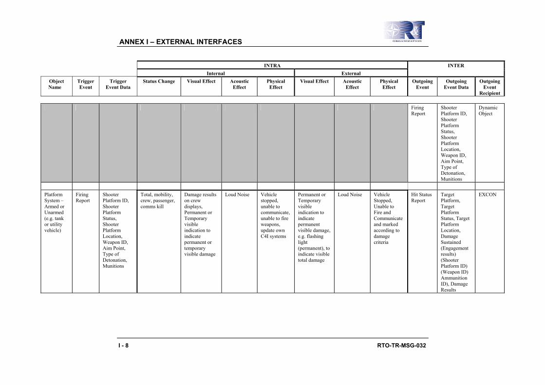
ANNEX I – EXTERNAL INTERFACES
I - 8 RTO-TR-MSG-032
INTRA Internal External
INTER
Object Name
Trigger Event
Trigger Event Data
Status Change Visual Effect Acoustic Effect
Physical Effect
Visual Effect Acoustic Effect
Physical Effect
Outgoing Event
Outgoing Event Data
Outgoing Event
Recipient
Firing Report
Shooter Platform ID, Shooter Platform Status, Shooter Platform Location, Weapon ID, Aim Point, Type of Detonation, Munitions
Dynamic Object
Platform System – Armed or Unarmed (e.g. tank or utility vehicle)
Firing Report
Shooter Platform ID, Shooter Platform Status, Shooter Platform Location, Weapon ID, Aim Point, Type of Detonation, Munitions
Total, mobility, crew, passenger, comms kill
Damage results on crew displays, Permanent or Temporary visible indication to indicate permanent or temporary visible damage
Loud Noise Vehicle stopped, unable to communicate, unable to fire weapons, update own C4I systems
Permanent or Temporary visible indication to indicate permanent visible damage, e.g. flashing light (permanent), to indicate visible total damage
Loud Noise Vehicle Stopped, Unable to Fire and Communicate and marked according to damage criteria
Hit Status Report
Target Platform, Target Platform Status, Target Platform Location, Damage Sustained (Engagement results) (Shooter Platform ID) (Weapon ID) Ammunition ID), Damage Results
EXCON

ANNEX I – EXTERNAL INTERFACES
RTO-TR-MSG-032 I - 9
INTRA Internal External
INTER
Object Name
Trigger Event
Trigger Event Data
Status Change Visual Effect Acoustic Effect
Physical Effect
Visual Effect Acoustic Effect
Physical Effect
Outgoing Event
Outgoing Event Data
Outgoing Event
Recipient
Hit Status Report
Target Platform, Target Platform Status, Target Platform Location, Damage Sustained (Engagement results) (Shooter Platform ID) (Weapon ID) Ammunition ID), Damage Results
O/C
Firing Report
Shooter Platform ID, Shooter Platform Status, Shooter Platform Location, Weapon ID, Aim Point, Type of Detonation, Munitions
Dynamic Object
Personnel Firing
Report Shooter Platform ID, Shooter Platform Status, Shooter Platform
Casualty status, wounds
Engagement results on displays
Yes plus near miss indication
Unable to communicate, unable to fire weapons, update own C4I systems, mobility
Permanent visible indication to indicate permanent visible damage, e.g. flashing light (permanent), to indicate visible total damage
Unable to communicate, unable to fire weapons, update own C4I systems, mobility
Hit Status Report
Target Platform, Target Platform Status, Target Platform Location,
EXCON

ANNEX I – EXTERNAL INTERFACES
I - 10 RTO-TR-MSG-032
INTRA Internal External
INTER
Object Name
Trigger Event
Trigger Event Data
Status Change Visual Effect Acoustic Effect
Physical Effect
Visual Effect Acoustic Effect
Physical Effect
Outgoing Event
Outgoing Event Data
Outgoing Event
Recipient
Location, Weapon ID, Aim Point, Type of Detonation, Munitions
reduction reduction Damage Sustained (Engagement results) (Shooter Platform ID) (Weapon ID) Ammunition ID), Damage Results
Hit Status Report
Target Platform, Target Platform Status, Target Platform Location, Damage Sustained (Engagement results) (Shooter Platform ID) (Weapon ID) Ammunition ID), Damage Results
O/C
Personnel Firing
Report Shooter Platform ID, Shooter Platform Status, Shooter Platform Location, Weapon ID,
Casualty status, wounds
Damage results on displays
Yes – Noise Unable to communicate, unable to fire weapons, update own C4I systems, mobility reduction
Permanent visible indication to indicate permanent visible damage, e.g. flashing light (permanent), to indicate visible total damage
Unable to communicate, unable to fire weapons, update own C4I systems, mobility reduction
Hit Status Report
Target Platform, Target Platform Status, Target Platform Location, Damage Sustained
EXCON

ANNEX I – EXTERNAL INTERFACES
RTO-TR-MSG-032 I - 11
INTRA Internal External
INTER
Object Name
Trigger Event
Trigger Event Data
Status Change Visual Effect Acoustic Effect
Physical Effect
Visual Effect Acoustic Effect
Physical Effect
Outgoing Event
Outgoing Event Data
Outgoing Event
Recipient
Aim Point, Type of Detonation, Munitions
(Engagement results) (Shooter Platform ID) (Weapon ID) Ammunition ID), Damage Results
Hit Status Report
Target Platform, Target Platform Status, Target Platform Location, Damage Sustained (Engagement results) (Shooter Platform ID) (Weapon ID) Ammunition ID), Damage Results
O/C

ANNEX I – EXTERNAL INTERFACES
I - 12 RTO-TR-MSG-032
INTRA Internal External
INTER
Object Name
Trigger Event
Trigger Event Data
Status Change Visual Effect Acoustic Effect
Physical Effect
Visual Effect Acoustic Effect
Physical Effect
Outgoing Event
Outgoing Event Data
Outgoing Event
Recipient
Building Firing Report
Shooter Platform ID, Shooter Platform Status, Shooter Platform Location, Weapon ID, Aim Point, Type of Detonation, Munitions
Degree of Damage (Total Destruction, Partial Destruction (e.g. rooms, stairwell), Permanent or Temporary Unusable), Contamination State
Engagement results on inside of building, Permanent or Temporary visible indication to indicate permanent/ temporary visible damage, e.g. blocking doors/windows/stairs, fire, smoke, rounds ricocheting off walls, lighting, building motion (shaking).
Yes plus near miss indication (e.g. loud bang, sound of rifle/ MG fire)
Unable to enter or exit a room inside, move up/down stairs, unable to provide protection, change in IR properties, lines of sight impacted, motion
Engagement results on outside of building, Permanent or Temporary visible indication to indicate permanent/ temporary visible damage, e.g. blocking doors/windows/outside stairwells, fire, smoke, rounds ricocheting off outside walls, lighting.
Yes plus near miss indication (loud bang)
Unable to enter or exit a building, unable to provide protection or cover, change in IR properties, lines of sight impacted
Hit Status Report
Target Platform, Target Platform Status, Target Platform Location, Damage Sustained (Engagement results) (Shooter Platform ID) (Weapon ID) Ammunition ID), Damage Results
EXCON
Hit Status Report
Target Platform, Target Platform Status, Target Platform Location, Damage Sustained (Engagement results) (Shooter Platform ID) (Weapon ID) Ammunition ID), Damage Results
O/C

ANNEX I – EXTERNAL INTERFACES
RTO-TR-MSG-032 I - 13
INTRA Internal External
INTER
Object Name
Trigger Event
Trigger Event Data
Status Change Visual Effect Acoustic Effect
Physical Effect
Visual Effect Acoustic Effect
Physical Effect
Outgoing Event
Outgoing Event Data
Outgoing Event
Recipient
Firing Report
Shooter Platform ID, Shooter Platform Status, Shooter Platform Location, Weapon ID, Aim Point, Type of Detonation, Munitions
Dynamic Object (impact on personnel/vehicle inside or outside proximity of building)
Transferable Weapon (Rifle, ATK, Pistol, Mortar, Grenade, etc.)
Firing Report
Shooter Platform ID, Shooter Platform Status, Shooter Platform Location, Weapon ID, Aim Point, Type of Detonation, Munitions
Weapon disabled None None Cannot operate weapon
Weapon status Potentially in future when you have acoustic weapon effects instead of blank ammo, e.g. "no bang but click"
Cannot operate weapon
Hit Status Report
Shooter Platform ID (New), Weapon ID, Ammunition ID, Shooter Platform Status
EXCON
Hit Status Report
Shooter Platform ID (New), Weapon ID, Ammunition ID, Shooter Platform Status
O/C
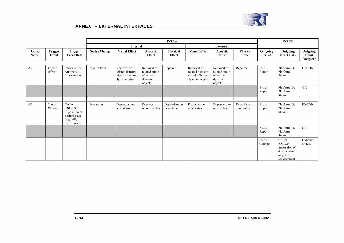
ANNEX I – EXTERNAL INTERFACES
I - 14 RTO-TR-MSG-032
INTRA Internal External
INTER
Object Name
Trigger Event
Trigger Event Data
Status Change Visual Effect Acoustic Effect
Physical Effect
Visual Effect Acoustic Effect
Physical Effect
Outgoing Event
Outgoing Event Data
Outgoing Event
Recipient
All Repair effect
Personnel or Automated Intervention
Repair Status Removal of related damage visual effect on dynamic object
Removal of related audio effect on dynamic object
Repaired Removal of related damage visual effect on dynamic object
Removal of related audio effect on dynamic object
Repaired Status Report
Platform ID, Platform Status
EXCON
Status Report
Platform ID, Platform Status
O/C
All Status
Change O/C or EXCON imposition of desired state (e.g. kill, repair, reset)
New status Dependent on new status
Dependent on new status
Dependent on new status
Dependent on new status
Dependent on new status
Dependent on new status
Status Report
Platform ID, Platform Status
EXCON
Status Report
Platform ID, Platform Status
O/C
Status Change
O/C or EXCON imposition of desired state (e.g. kill, repair, reset)
Dynamic Object
RTO-TR-MSG-032 J - 1
Annex J – INTEROPERABILITY CODE SETS
The following appendices support the UCATT proposals for standardisation proposed in Chapter 7:
• Appendix J1: Weapon System Table (Example);
• Appendix J2: Possible Target designating dynamic object code;
• Appendix J3 : Possible External Report Manifestations; and
• Appendix J4: Legacy OSAG – Code Enhancement Options.

ANNEX J – INTEROPERABILITY CODE SETS
J - 2 RTO-TR-MSG-032
Appendix J1: WEAPON SYSTEM TABLE (EXAMPLE)
The FIBUA/MOUT WG has started to populate weapon system tables in an effort to capture existing weapon systems that will have a role in the FIBUA/MOUT environment. As a general rule all weapon systems used for open terrain will be relevant for FIBUA/MOUT training because the FIBUA/MOUT scenario includes the approach towards the object (city, village, …), the military action inside the object and might also include the leaving of the object.
The weapon tables are incomplete and are provided as an example with the intent to initiate a thought process throughout the user community. The goal is to have every country that is interested in developing interoperability to support the process by entering it is non-confidential weapon type data into the appropriate table. New tables of weapon systems not yet included in this process can be created if necessary.
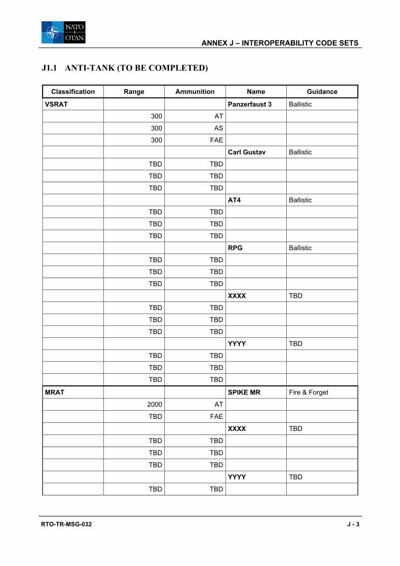
ANNEX J – INTEROPERABILITY CODE SETS
RTO-TR-MSG-032 J - 3
J1.1 ANTI-TANK (TO BE COMPLETED)
Classification Range Ammunition Name Guidance
VSRAT Panzerfaust 3 Ballistic
300 AT
300 AS
300 FAE
Carl Gustav Ballistic
TBD TBD
TBD TBD
TBD TBD
AT4 Ballistic
TBD TBD
TBD TBD
TBD TBD
RPG Ballistic
TBD TBD
TBD TBD
TBD TBD
XXXX TBD
TBD TBD
TBD TBD
TBD TBD
YYYY TBD
TBD TBD
TBD TBD
TBD TBD
MRAT SPIKE MR Fire & Forget
2000 AT
TBD FAE
XXXX TBD
TBD TBD
TBD TBD
TBD TBD
YYYY TBD
TBD TBD

ANNEX J – INTEROPERABILITY CODE SETS
J - 4 RTO-TR-MSG-032
Classification Range Ammunition Name Guidance
TBD TBD
TBD TBD
LRAT SPIKE LR Fire & Forget/Observe
4000 AT
TBD TBD
TBD TBD
HOT Wire Guided
TBD TBD
TBD TBD
TBD TBD
SAGGER Wire Guided
3000 TBD
TBD TBD
TBD TBD
VLRAT KONKURS
> 4000 AT
TBD TBD
TBD TBD

ANNEX J – INTEROPERABILITY CODE SETS
RTO-TR-MSG-032 J - 5
J1.2 MINES (TO BE COMPLETED)
Classification Use Effect Name
Anti-Tank
Surface Blast UKM-63
Anti-Tank DM 31
Horizontal Anti-Tank RL Schwer
TBD TBD TBD
TBD TBD TBD
TBD TBD TBD
Anti-Personnel
Surface Blast TBD
Horizontal Directed Bullets Claymore
Jump Mine Fragmentation TBD
TBD TBD TBD
TBD TBD TBD
TBD TBD TBD

ANNEX J – INTEROPERABILITY CODE SETS
J - 6 RTO-TR-MSG-032
J1.3 HAND GRENADES (TO BE COMPLETED)
Classification Type Range Effect Name
Lethal Fragmentation
Thrown approx. 30 m Lethal up to 25 m DM 61
TBD TBD TBD
TBD TBD TBD
TBD TBD TBD
Concussion
Thrown approx. 30 m Lethal up to 15 m
in Closed Spaces M 100
TBD TBD TBD
TBD TBD TBD
TBD TBD TBD
Anti-Tank
Thrown approx. 30 m Thrown Directed
by Parachute 58 K-100
TBD TBD TBD
Less Lethal Concussion
Thrown approx. 30 m
HGR 85
TBD TBD TBD
TBD TBD TBD
TBD TBD TBD
Non-Lethal Stungrenade
Thrown approx. 30 m Flashbang
Smoke
Thrown approx. 30 m TBD
TBD TBD TBD
Teargas
Thrown approx. 30 m TBD
TBD TBD TBD
Rubber Bullets
Thrown approx. 30 m TBD TBD
TBD TBD TBD
TBD TBD TBD

ANNEX J – INTEROPERABILITY CODE SETS
RTO-TR-MSG-032 J - 7
J1.4 RIFLES (TO BE COMPLETED)
Classification Calibre Effect Range Name Remarks
Sub-MG
9 mm 0 – 150 m MP5
9 mm 0 – 150 m KGP9
4.7 mm PPW
TBD XXX
TBD YYY
TBD ZZZ
Carbine
5.56 mm 0 – 300 m C8
7.62 mm TBD TBD
TBD XXX
TBD YYY
Assault
5.56 mm 0 – 600 m C7
7.62 mm 0 – 600 m AK63D
TBD XXX
TBD YYY
TBD ZZZ
MRSW
7.62 mm 500 – 1500 m SVD
.338 TBD Timberwolf
TBD XXX
TBD YYY
TBD ZZZ
LRSW
12.7 mm +1500 m Barret
12.7 mm +1500 m Gepard M1
14.5 mm TBD Elephant M1
TBD XXX
TBD YYY
TBD ZZZ

ANNEX J – INTEROPERABILITY CODE SETS
J - 8 RTO-TR-MSG-032
J1.5 MACHINE GUNS (TO BE COMPLETED)
Classification Calibre Effect range Max Range Name
Machine Guns
Light
5.56 mm 400 m 800 m Minimi
5.56 mm 400 m 800 m C9
7.62 mm 800 m RPK
TBD TBD TBD TBD
Medium
7.62 mm 1200 m PKM
7.62 mm 1200 m M-60
7.62 mm 1200 m C6
7.62 mm 1200 m FN MAG
TBD TBD TBD TBD
Heavy
12.7 mm 800 m 1500 m DSK
12.7 mm 800 m 1500 m M2 Browning
14.5 mm 1200 m 2000 m NSVT
TBD TBD TBD TBD
Chain Gun
7.62 mm 800 m 1200 m PKT
14.5 mm 1000 m 1800 m KPVT
20 mm 1500 m 2000 m TBD
25 mm 1500 m 3000 m TBD
30 mm 2500 m 3000 m 2A72
30 mm 2500 m 3000 m BushMaster
TBD TBD TBD TBD

ANNEX J – INTEROPERABILITY CODE SETS
RTO-TR-MSG-032 J - 9
J1.6 GRENADE LAUNCHERS
Classification Calibre Effect Range Name Remarks
Low Velocity
40 mm HE 300 m or less HK-79 Underslung GL
40 mm HE 300 m or less M-203 Underslung GL
TBD TBD TBD TBD TBD
TBD HE/DP M-79 Grenade Launcher
FAE TBD TBD TBD
Smoke TBD TBD TBD
Teargas TBD TBD TBD
Non-Lethal TBD TBD TBD
TBD TBD TBD TBD TBD
TBD TBD TBD TBD TBD
TBD TBD TBD TBD TBD
High Velocity
40 mm HE 2000 m or less MK-19 Programmable Time of
Explosion
40 mm HE 2000 m or less AGS-17 Programmable Time of
Explosion
TBD HE/DP
TBD TBD TBD TBD TBD
TBD TBD TBD TBD TBD
TBD TBD TBD TBD TBD

ANNEX J – INTEROPERABILITY CODE SETS
J - 10 RTO-TR-MSG-032
J1.7 MORTAR (TO BE COMPLETED)
Classification Calibre Effect Fuse Range ´Name
Light
60 mm
HE Impact Min.: Max.: TBD
TBD TBD
Illumination TBD TBD TBD
TBD TBD TBD
Smoke TBD TBD TBD
TBD TBD TBD
TBD TBD TBD TBD
TBD
TBD TBD TBD TBD
Medium
82 mm
HE Impact or Delay Min.: Max.:
TBD TBD
TBD TBD
Illumination TBD TBD TBD
TBD TBD TBD
Smoke TBD TBD TBD
TBD TBD TBD
Anti-Tank TBD TBD TBD
TBD TBD TBD
Heavy
120 mm
HE
Impact or Delay Min.: Max.:
TBD TBD
TBD TBD
Illumination
TBD TBD TBD
TBD TBD TBD

ANNEX J – INTEROPERABILITY CODE SETS
RTO-TR-MSG-032 J - 11
Classification Calibre Effect Fuse Range ´Name
TBD TBD TBD
Smoke
TBD TBD TBD
TBD TBD TBD
Anti-Tank
TBD TBD TBD
TBD TBD TBD

ANNEX J – INTEROPERABILITY CODE SETS
J - 12 RTO-TR-MSG-032
J1.8 ARTILLERY TUBE (TO BE COMPLETED)
Classification Calibre Effect Fuse Range Name
Light (≤ 105)
105 mm
HE
Impact TBD TBD
Delay TBD TBD
TBD TBD TBD
Illumination
TBD TBD TBD
Smoke
TBD TBD TBD
Anti-Tank
Guided TBD TBD
Unguided TBD TBD
Medium 106 – 154
150 mm .:
HE
Impact TBD TBD
Delay TBD TBD
TBD TBD TBD
Illumination
TBD TBD TBD
Smoke
TBD TBD TBD
Anti-Tank
Guided TBD TBD
Unguided TBD TBD
Scatter Mines
TBD TBD TBD
Chemical Warheads
TBD TBD TBD
Nuclear Warheads
TBD TBD TBD

ANNEX J – INTEROPERABILITY CODE SETS
RTO-TR-MSG-032 J - 13
Classification Calibre Effect Fuse Range Name
Heavy 155 or More
155 mm
HE
Impact TBD TBD
Delay TBD TBD
TBD TBD TBD
Illumination
TBD TBD TBD
Smoke
TBD TBD TBD
Anti-Tank
Guided TBD TBD
Unguided TBD TBD
Scatter Mines
TBD TBD TBD
Chemical Warheads
TBD TBD TBD
Nuclear Warheads
TBD TBD TBD
TBD
TBD TBD TBD

ANNEX J – INTEROPERABILITY CODE SETS
J - 14 RTO-TR-MSG-032
J1.9 ARTILLERY ROCKET (TO BE COMPLETED)
Classification Caliber Effect Fuse Range Name
Light TBD
HE
Impact TBD TBD
Delay TBD TBD
Programmable TBD TBD
TBD TBD TBD
Bomblets
TBD TBD TBD
Chemical Warheads
TBD TBD TBD
Nuclear Warheads
TBD TBD TBD
FAE
TBD TBD TBD
Heavy
122 mm
HE
Impact TBD TBD
Delay TBD TBD
Programmable TBD BM-21
Programmable TBD MLRS
TBD TBD TBD
Bomblets
Impact TBD GRAD
TBD TBD TBD
Chemical Warheads
TBD TBD TBD
Nuclear Warheads
TBD TBD TBD
FAE
TBD TBD TBD

ANNEX J – INTEROPERABILITY CODE SETS
RTO-TR-MSG-032 J - 15
J1.10 THERMOBARIC (TO BE COMPLETED)
Classification Delivery Caliber Effect Range Name
FAE
Bombs
TBD FAE TBD TBD
TBD FAE TBD TBD
Rocket Launcher
TBD FAE TBD TBD
TBD FAE TBD TBD
Artillery Grenades
TBD FAE TBD TBD
TBD FAE TBD TBD
Low Velocity Grenades
TBD FAE TBD TBD
TBD FAE TBD TBD
Flamethrower
TBD TBD TBD TBD
TBD TBD TBD TBD

ANNEX J – INTEROPERABILITY CODE SETS
J - 16 RTO-TR-MSG-032
J1.11 LESS LETHAL WEAPON (TO BE COMPLETED)
Classification Delivery Caliber Effect Range Name
Non-Lethal
ShotGun
TBD TBD TBD TBD
Grenades
TBD TBD TBD TBD
Grenade Launchers
TBD TBD TBD TBD
Sprays
Liquid TBD TBD TBD
Moisture TBD TBD TBD
Gas TBD TBD TBD
TBD TBD TBD TBD
Gas
TBD TBD TBD TBD
Less Lethal
ShotGun
TBD TBD TBD TBD
Grenades
TBD TBD TBD TBD
Grenade Launchers
TBD TBD TBD TBD
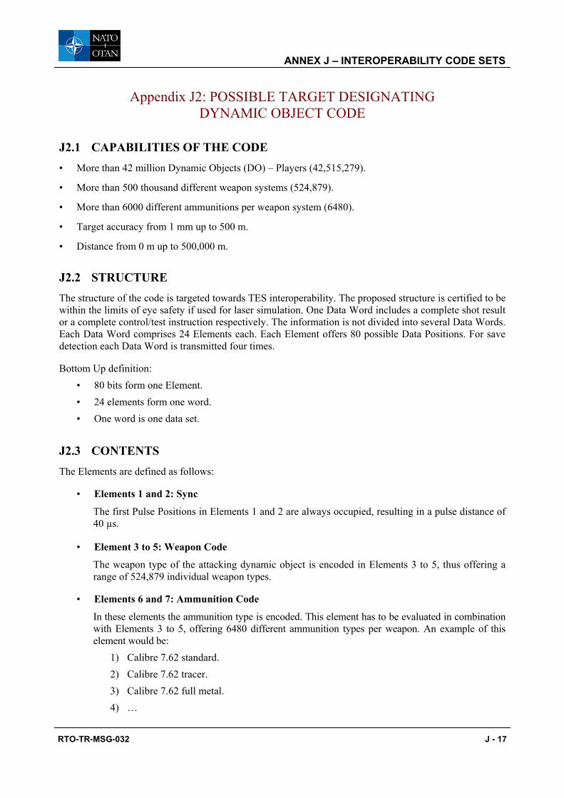
ANNEX J – INTEROPERABILITY CODE SETS
RTO-TR-MSG-032 J - 17
Appendix J2: POSSIBLE TARGET DESIGNATING DYNAMIC OBJECT CODE
J2.1 CAPABILITIES OF THE CODE • More than 42 million Dynamic Objects (DO) – Players (42,515,279).
• More than 500 thousand different weapon systems (524,879).
• More than 6000 different ammunitions per weapon system (6480).
• Target accuracy from 1 mm up to 500 m.
• Distance from 0 m up to 500,000 m.
J2.2 STRUCTURE The structure of the code is targeted towards TES interoperability. The proposed structure is certified to be within the limits of eye safety if used for laser simulation. One Data Word includes a complete shot result or a complete control/test instruction respectively. The information is not divided into several Data Words. Each Data Word comprises 24 Elements each. Each Element offers 80 possible Data Positions. For save detection each Data Word is transmitted four times.
Bottom Up definition: • 80 bits form one Element. • 24 elements form one word. • One word is one data set.
J2.3 CONTENTS The Elements are defined as follows:
• Elements 1 and 2: Sync
The first Pulse Positions in Elements 1 and 2 are always occupied, resulting in a pulse distance of 40 µs.
• Element 3 to 5: Weapon Code
The weapon type of the attacking dynamic object is encoded in Elements 3 to 5, thus offering a range of 524,879 individual weapon types.
• Elements 6 and 7: Ammunition Code
In these elements the ammunition type is encoded. This element has to be evaluated in combination with Elements 3 to 5, offering 6480 different ammunition types per weapon. An example of this element would be:
1) Calibre 7.62 standard. 2) Calibre 7.62 tracer. 3) Calibre 7.62 full metal. 4) …

ANNEX J – INTEROPERABILITY CODE SETS
J - 18 RTO-TR-MSG-032
Remark on ammunition code future capabilities: The Elements 3 to 7 are providing enough code capability for 524,879 weapons with 6480 ammunition types per weapon. This should be sufficient for the next 100 years of weapon and ammunition development.
• Elements 8 to 12 and 14: Position Code (azimuth: x and elevation: y)
Deviation of hit position in azimuth and elevation as measured by the attacking system in relation to the centre of the target. The value range is from 1 mm up to more than 518 m.
Remark on position code future capabilities: This element ensures that even a 500 m miss can still be transferred to the target. The resolution down to millimeters should be sufficient for all developments within the next 50 years.
• Elements 16 to 18: Hit Distance
The hit distance is the sum of the values given in Elements 16 to 18 in meters. This value ranges from 0 m all the way to 505,600 m.
The Element 18 codes 18-79 and 18-80 are used to transmit a switch information to the other system to enhance the code scheme even more (providing two possible sub-sets of the code).
• Elements 19 to 22: Identity Code
The Player ID number (PID) of the attacking simulator is encoded in Element 19 to 22, thus offering a range of more than 41 million possible players.
• Element 23: Flight Time Code
The flight time of any ammunition can be coded into Element 23 offering a flight time in seconds up to 80 sec.
• Element 24: Checksum
The checksum is derived summing up the Elements 3 to 23, modulo 80. It is used to determine the validity of any received code.
Code 18.79, 18.80: Switch (e.g. Umpire Definition Codes)
The Element 18 codes 18.79 and 18.80 are used to transmit a switch information to the other system to enhance the code scheme even more (providing two possible sub-sets of the code).
• Elements 13, 15 and 23: Reserve
The code provides 3 reserve elements that can be used to implement flight time codes, e.g. zero codes and other elements needed in the future.

ANNEX J – INTEROPERABILITY CODE SETS
RTO-TR-MSG-032 J - 19
J2.4 CONTENTS TABLES
Element 1 Element 2 Element 3 Element 4 Element 5 Element 6
Number Sync Sync Weapon2 Weapon1 Weapon3 Ammo1
1 Sync1 Sync2 80 0 6480 0
2 – – 160 1 12960 1
3 – – 240 2 19440 2
4 – – 320 3 25920 3
5 – – 400 4 32400 4
6 – – 480 5 38880 5
7 – – 560 6 45360 6
8 – – 640 7 51840 7
9 – – 720 8 58320 8
10 – – 800 9 64800 9
11 – – 880 10 71280 10
12 – – 960 11 77760 11
13 – – 1040 12 84240 12
14 – – 1120 13 90720 13
15 – – 1200 14 97200 14
16 – – 1280 15 103680 15
17 – – 1360 16 110160 16
18 – – 1440 17 116640 17
19 – – 1520 18 123120 18
20 – – 1600 19 129600 19
21 – – 1680 20 136080 20
22 – – 1760 21 142560 21
23 – – 1840 22 149040 22
24 – – 1920 23 155520 23
25 – – 2000 24 162000 24
26 – – 2080 25 168480 25
27 – – 2160 26 174960 26
28 – – 2240 27 181440 27
29 – – 2320 28 187920 28
30 – – 2400 29 194400 29
31 – – 2480 30 200880 30

ANNEX J – INTEROPERABILITY CODE SETS
J - 20 RTO-TR-MSG-032
Element 1 Element 2 Element 3 Element 4 Element 5 Element 6
Number Sync Sync Weapon2 Weapon1 Weapon3 Ammo1
71 – – 5680 70 460080 70
72 – – 5760 71 466560 71
73 – – 5840 72 473040 72
74 – – 5920 73 479520 73
75 – – 6000 74 486000 74
76 – – 6080 75 492480 75
77 – – 6160 76 498960 76
78 – – 6240 77 505440 77
79 – – 6320 78 511920 78
80 – – 6400 79 518400 79
Element 7 Element 8 Element 9 Element 10 Element 11 Element 12
Number Ammo2 delta x [cm] delta y [mm] delta y [cm] delta x [mm] delta y [m]
1 80 8 0 8 0 6,48
2 160 16 1 16 1 12,96
3 240 24 2 24 2 19,44
4 320 32 3 32 3 25,92
5 400 40 4 40 4 32,4
6 480 48 5 48 5 38,88
7 560 56 6 56 6 45,36
8 640 64 7 64 7 51,84
9 720 72 8 72 8 58,32
10 800 80 9 80 9 64,8
11 880 88 10 88 10 71,28
12 960 96 11 96 11 77,76
13 1040 104 12 104 12 84,24
14 1120 112 13 112 13 90,72
15 1200 120 14 120 14 97,2
16 1280 128 15 128 15 103,68
17 1360 136 16 136 16 110,16
18 1440 144 17 144 17 116,64
19 1520 152 18 152 18 123,12

ANNEX J – INTEROPERABILITY CODE SETS
RTO-TR-MSG-032 J - 21
Element 7 Element 8 Element 9 Element 10 Element 11 Element 12
Number Ammo2 delta x [cm] delta y [mm] delta y [cm] delta x [mm] delta y [m]
20 1600 160 19 160 19 129,6
21 1680 168 20 168 20 136,08
22 1760 176 21 176 21 142,56
23 1840 184 22 184 22 149,04
24 1920 192 23 192 23 155,52
25 2000 200 24 200 24 162
26 2080 208 25 208 25 168,48
27 2160 216 26 216 26 174,96
28 2240 224 27 224 27 181,44
29 2320 232 28 232 28 187,92
30 2400 240 29 240 29 194,4
31 2480 248 30 248 30 200,88
71 5680 568 70 568 70 460,08
72 5760 576 71 576 71 466,56
73 5840 584 72 584 72 473,04
74 5920 592 73 592 73 479,52
75 6000 600 74 600 74 486
76 6080 608 75 608 75 492,48
77 6160 616 76 616 76 498,96
78 6240 624 77 624 77 505,44
79 6320 632 78 632 78 511,92
80 6400 640 79 640 79 518,4
Element 13 Element 14 Element 15 Element 16 Element 17 Element 18
Number Reserve1 Delta x [m] Reserve2 Distance1 Distance3 Distance2
1 6,48 0 6320 80
2 12,96 1 12640 160
3 19,44 2 18960 240
4 25,92 3 25280 320
5 32,4 4 31600 400
6 38,88 5 37920 480
7 45,36 6 44240 560

ANNEX J – INTEROPERABILITY CODE SETS
J - 22 RTO-TR-MSG-032
Element 13 Element 14 Element 15 Element 16 Element 17 Element 18
Number Reserve1 Delta x [m] Reserve2 Distance1 Distance3 Distance2
8 51,84 7 50560 640
9 58,32 8 56880 720
10 64,8 9 63200 800
11 71,28 10 69520 880
12 77,76 11 75840 960
13 84,24 12 82160 1040
14 90,72 13 88480 1120
15 97,2 14 94800 1200
16 103,68 15 101120 1280
17 110,16 16 107440 1360
18 116,64 17 113760 1440
19 123,12 18 120080 1520
20 129,6 19 126400 1600
21 136,08 20 132720 1680
22 142,56 21 139040 1760
23 149,04 22 145360 1840
24 155,52 23 151680 1920
25 162 24 158000 2000
26 168,48 25 164320 2080
27 174,96 26 170640 2160
28 181,44 27 176960 2240
29 187,92 28 183280 2320
30 194,4 29 189600 2400
31 200,88 30 195920 2480
71 460,08 70 448720 5680
72 466,56 71 455040 5760
73 473,04 72 461360 5840
74 479,52 73 467680 5920
75 486 74 474000 6000
76 492,48 75 480320 6080
77 498,96 76 486640 6160
78 505,44 77 492960 6240

ANNEX J – INTEROPERABILITY CODE SETS
RTO-TR-MSG-032 J - 23
Element 13 Element 14 Element 15 Element 16 Element 17 Element 18
Number Reserve1 Delta x [m] Reserve2 Distance1 Distance3 Distance2
79 511,92 78 499280 Switch 1
80 518,4 79 505600 Switch 2
Element 19 Element 20 Element 21 Element 22 Element 23 Element 24
Number PID4 PID1 PID3 PID2 Flight T [s] CheckS
1 524880 0 6480 80 0 0
2 1049760 1 12960 160 1 1
3 1574640 2 19440 240 2 2
4 2099520 3 25920 320 3 3
5 2624400 4 32400 400 4 4
6 3149280 5 38880 480 5 5
7 3674160 6 45360 560 6 6
8 4199040 7 51840 640 7 7
9 4723920 8 58320 720 8 8
10 5248800 9 64800 800 9 9
11 5773680 10 71280 880 10 10
12 6298560 11 77760 960 11 11
13 6823440 12 84240 1040 12 12
14 7348320 13 90720 1120 13 13
15 7873200 14 97200 1200 14 14
16 8398080 15 103680 1280 15 15
17 8922960 16 110160 1360 16 16
18 9447840 17 116640 1440 17 17
19 9972720 18 123120 1520 18 18
20 10497600 19 129600 1600 19 19
21 11022480 20 136080 1680 20 20
22 11547360 21 142560 1760 21 21
23 12072240 22 149040 1840 22 22
24 12597120 23 155520 1920 23 23
25 13122000 24 162000 2000 24 24
26 13646880 25 168480 2080 25 25
27 14171760 26 174960 2160 26 26

ANNEX J – INTEROPERABILITY CODE SETS
J - 24 RTO-TR-MSG-032
Element 19 Element 20 Element 21 Element 22 Element 23 Element 24
Number PID4 PID1 PID3 PID2 Flight T [s] CheckS
28 14696640 27 181440 2240 27 27
29 15221520 28 187920 2320 28 28
30 15746400 29 194400 2400 29 29
31 16271280 30 200880 2480 30 30
71 37266480 70 460080 5680 660 70
72 37791360 71 466560 5760 720 71
73 38316240 72 473040 5840 780 72
74 38841120 73 479520 5920 840 73
75 39366000 74 486000 6000 900 74
76 39890880 75 492480 6080 960 75
77 40415760 76 498960 6160 1020 76
78 40940640 77 505440 6240 1080 77
79 41465520 78 511920 6320 1140 78
80 41990400 79 518400 6400 1200 79
J2.5 TIMING FOR TIME BASED CODING SYSTEMS (E.G. LASER SIMULATION)
For time based coding systems the following timing can be used to ensure a data transmission that covers the needs of 2020 scenarios. The following values are proposed since they are within the technological capacity of present systems. The timing, if applied with laser simulators, ensures eye safety class one over large distances (more than 6 km depending on technology pull):
• Each Pulse Interval (PI) has a length of 500 ns.
• Each element (80 PI) has a duration of 40 µs.
• 24 elements form one word with a duration of 960 µs.
• Each word is repeated 4 times with a spacing of 1 ms.
• A complete time based transmission therefore requires about 7 ms.
• Short transmission time to ensure code transmission without restrictions on weapon handling.
The timing is depicted in the following graph.
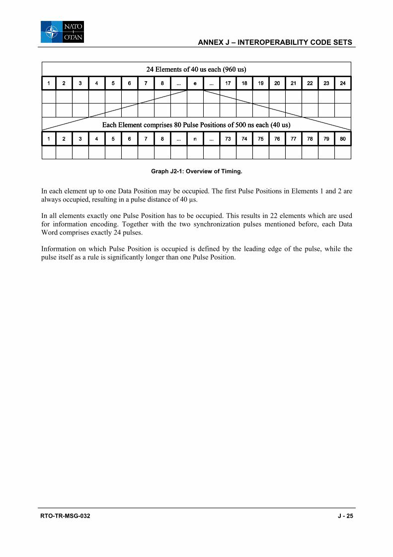
ANNEX J – INTEROPERABILITY CODE SETS
RTO-TR-MSG-032 J - 25
8079787776757473...n...87654321
Each Element comprises 80 Pulse Positions of 500 ns each (40 us)
2423222120191817...e...87654321
24 Elements of 40 us each (960 us)
8079787776757473...n...87654321
Each Element comprises 80 Pulse Positions of 500 ns each (40 us)
2423222120191817...e...87654321
24 Elements of 40 us each (960 us)
8079787776757473...n...87654321
Each Element comprises 80 Pulse Positions of 500 ns each (40 us)
2423222120191817...e...87654321
24 Elements of 40 us each (960 us)
Graph J2-1: Overview of Timing.
In each element up to one Data Position may be occupied. The first Pulse Positions in Elements 1 and 2 are always occupied, resulting in a pulse distance of 40 µs.
In all elements exactly one Pulse Position has to be occupied. This results in 22 elements which are used for information encoding. Together with the two synchronization pulses mentioned before, each Data Word comprises exactly 24 pulses.
Information on which Pulse Position is occupied is defined by the leading edge of the pulse, while the pulse itself as a rule is significantly longer than one Pulse Position.

ANNEX J – INTEROPERABILITY CODE SETS
J - 26 RTO-TR-MSG-032
Appendix J3: POSSIBLE EXTERNAL REPORT MANIFESTATIONS
J3.1 EFFECTS REPRESENTATION (ER) – RELEVANT EVENTS ON THE SIDE OF THE SHOOTER
Table J3-1 shows examples of possible engagement events on a shooter, the kind of representation, a means of representing the effect, an ER example and a blank space for future FIBUA/MOUT WG comment.
Table J3-1: Examples of Engagement Events
Engagement Event Shooter
Kind of Representation
Means of Representing Effect
ER Example FIBUA/MOUT Comment
Small Arms shot Acoustical, optical
Pyrotechnics Blank ammo bang and flash
Anti-tank fire Optical Pyrotechnics White flash, bang and smoke
Battle-tank, Anti-aircraft or Howitzer fire
Acoustical, optical
Pyrotechnics White flash, loud bang and smoke
Anti-tank Helicopter fire
Optical Pyrotechnics (safety?), flashing lights
White flash, smoke/flare (?)
J3.2 ER-RELEVANT EVENTS ON TARGETS
Table J3-2 shows examples of possible engagement events and their respective representation on the targets.
Table J3-2: Examples of Effects on Targets
Target Engagement Event
Engagement Result
Kind of Representation
Means of Representing
Effect
ER Example
FIBUA/ MOUT
Comment
Personnel Direct/indirect weapon hit
Kill Acoustical Electro-acoustic
Long, loud beep
Personnel Direct/indirect weapon hit
Degree of wounds < kill
None – –
Vehicle Direct weapon hit
Total kill Acoustical, optical
Pyrotechnic, blinking lights
Red flare, loud bang, red smoke, permanent white flashing light
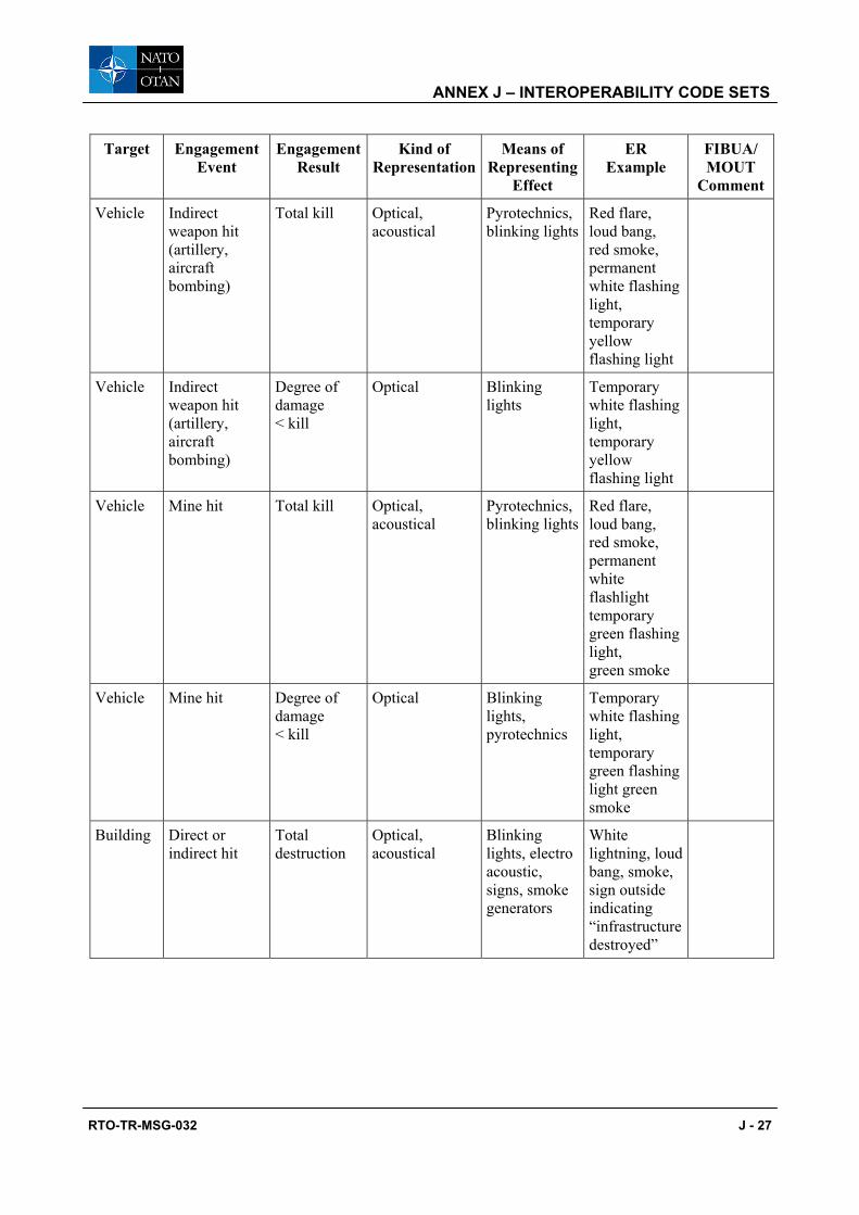
ANNEX J – INTEROPERABILITY CODE SETS
RTO-TR-MSG-032 J - 27
Target Engagement Event
Engagement Result
Kind of Representation
Means of Representing
Effect
ER Example
FIBUA/ MOUT
Comment
Vehicle Indirect weapon hit (artillery, aircraft bombing)
Total kill Optical, acoustical
Pyrotechnics, blinking lights
Red flare, loud bang, red smoke, permanent white flashing light, temporary yellow flashing light
Vehicle Indirect weapon hit (artillery, aircraft bombing)
Degree of damage < kill
Optical Blinking lights
Temporary white flashing light, temporary yellow flashing light
Vehicle Mine hit Total kill Optical, acoustical
Pyrotechnics, blinking lights
Red flare, loud bang, red smoke, permanent white flashlight temporary green flashing light, green smoke
Vehicle Mine hit Degree of damage < kill
Optical Blinking lights, pyrotechnics
Temporary white flashing light, temporary green flashing light green smoke
Building Direct or indirect hit
Total destruction
Optical, acoustical
Blinking lights, electro acoustic, signs, smoke generators
White lightning, loud bang, smoke, sign outside indicating “infrastructure destroyed”
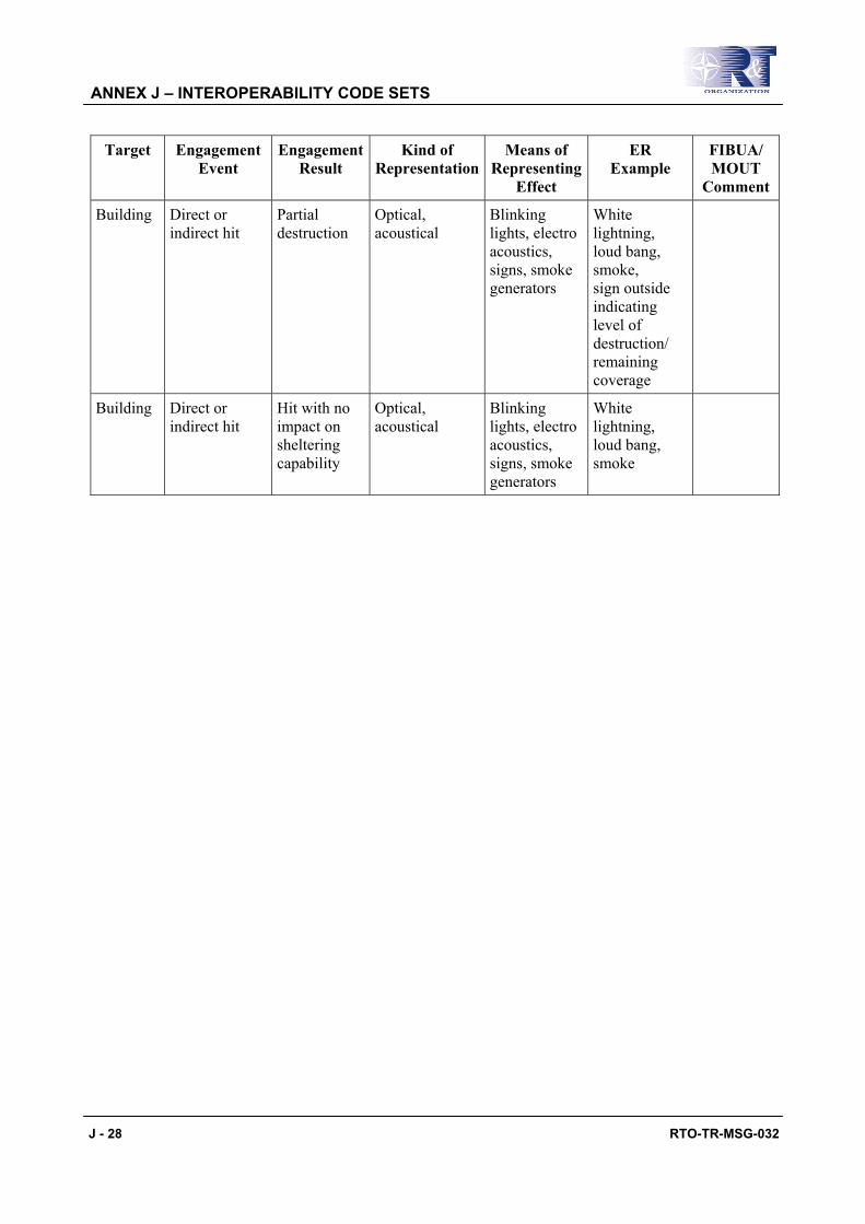
ANNEX J – INTEROPERABILITY CODE SETS
J - 28 RTO-TR-MSG-032
Target Engagement Event
Engagement Result
Kind of Representation
Means of Representing
Effect
ER Example
FIBUA/ MOUT
Comment
Building Direct or indirect hit
Partial destruction
Optical, acoustical
Blinking lights, electro acoustics, signs, smoke generators
White lightning, loud bang, smoke, sign outside indicating level of destruction/ remaining coverage
Building Direct or indirect hit
Hit with no impact on sheltering capability
Optical, acoustical
Blinking lights, electro acoustics, signs, smoke generators
White lightning, loud bang, smoke

ANNEX J – INTEROPERABILITY CODE SETS
RTO-TR-MSG-032 J - 29
Appendix J4: LEGACY OSAG – CODE ENHANCEMENT OPTIONS
J4.1 INTRODUCTION
The UCATT TG proposes that the code transition phase should be complete by 2020 which is 13 years after the publication of this report. This appendix presents a conceptual means of how one of the currently established codes (the OSAG code) can be modified to achieve a level of interoperability that would enable the OSAG-code community to conduct joint training operations in the near term.
J4.2 BACKGROUND
Current users of OSAG compatible laser simulators have different laser code systems, e.g. Austria, Germany, Italy and the Netherlands are using OSAG while Finland and Norway are using a modified OSAG code. The United Kingdom, USA and Sweden among others are using their own code variants. In order to create a common laser code structure that supports both high fidelity and one way simulation one option would be to use the OSAG II laser code. The OSAG II will have approximately 170 ammunition codes available which are 2.5 times more than the present code. In OSAG only every 3rd laser pulse interval is used for an ammunition code. In OSAG II every laser pulse interval within a class can be used.
The OSAG II code would be an open and company independent standard. The OSAG II code is a code that defines the structure of the code itself and its content, i.e. the interpretation, in terms of ammunition type, of the different individual weapons.
J4.3 GUIDING PRINCIPLES
The following are guiding principles on how to achieve a code system that has a defined ammunition code structure and which allows unique user defined ammunitions to be implemented. A brief description would be to say that the OSAG II proposal is an introduction of 38 ammunition classes (categories) as schematically presented in the example at Table J4-1 below.
Every single one of these classes is defined by a generic ammunition code and the first ammunition code within the sequence of codes belonging to the applicable class is to be implemented and interpreted in the same way in every system supporting this new approach.
Each user (nation) can then choose and define unique ammunitions within the appropriate class, based on ammunition effect, using the remaining ammunition codes.
During joint training the 38 ammunition classes will be used to determine the effects of an engagement. The more precise, user (nation) specific ammunitions can be used during national (single user) training, enhancing the training fidelity by providing detailed information about the particular ammunition. During national training exercises the proposed concept ensures that all simulators will still be able to interpret the ammunition codes according to the locally defined tailoring with the unique ammunition code implementations that exist today.
During international exercises, the proposal eliminates the problem with undefined codes as all codes, unless identically defined, will be interpreted as the generic ammunition type of applicable class.
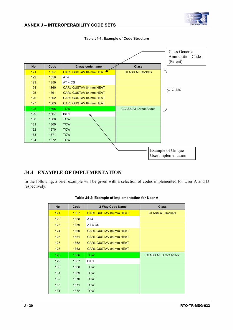
ANNEX J – INTEROPERABILITY CODE SETS
J - 30 RTO-TR-MSG-032
Table J4-1: Example of Code Structure
J4.4 EXAMPLE OF IMPLEMENTATION
In the following, a brief example will be given with a selection of codes implemented for User A and B respectively.
Table J4-2: Example of Implementation for User A
No Code 2-Way Code Name Class
121 1857 CARL GUSTAV 84 mm HEAT CLASS AT Rockets
122 1858 AT4
123 1859 AT 4 CS
124 1860 CARL GUSTAV 84 mm HEAT
125 1861 CARL GUSTAV 84 mm HEAT
126 1862 CARL GUSTAV 84 mm HEAT
127 1863 CARL GUSTAV 84 mm HEAT
128 1866 TOW CLASS AT Direct Attack
129 1867 Bill 1
130 1868 TOW
131 1869 TOW
132 1870 TOW
133 1871 TOW
134 1872 TOW
No Code 2-way code name Class
121 1857 CARL GUSTAV 84 mm HEAT CLASS AT Rockets 122 1858 AT4 123 1859 AT 4 CS 124 1860 CARL GUSTAV 84 mm HEAT 125 1861 CARL GUSTAV 84 mm HEAT 126 1862 CARL GUSTAV 84 mm HEAT
127 1863 CARL GUSTAV 84 mm HEAT
128 1866 TOW CLASS AT Direct Attack 129 1867 Bill 1 130 1868 TOW 131 1869 TOW 132 1870 TOW 133 1871 TOW
134 1872 TOW
Class
Example of Unique User implementation
Class Generic Ammunition Code (Parent)

ANNEX J – INTEROPERABILITY CODE SETS
RTO-TR-MSG-032 J - 31
Table J4-3: Example of Implementation for User B
No Code 2-Way Code Name Class
121 1857 CARL GUSTAV 84 mm HEAT CLASS AT Rockets 122 1858 PZF 3 123 1859 CARL GUSTAV 84 mm HEAT 124 1860 CARL GUSTAV 84 mm HEAT 125 1861 CARL GUSTAV 84 mm HEAT 126 1862 CARL GUSTAV 84 mm HEAT
127 1863 CARL GUSTAV 84 mm HEAT
128 1866 TOW CLASS AT Direct Attack 129 1867 MILAN 130 1868 TOW 131 1869 TOW 132 1870 TOW 133 1871 TOW
134 1872 TOW
As seen from Table J4-2 and Table J4-3 above the following would apply:
Fire Code by Country A Interpretation by User A Interpretation by User B
121 Generic Code Carl Gustav Heat Generic Code Carl Gustav Heat
122 AT4 PzF3
123 AT4 CS Generic Code Carl Gustav Heat
128 Generic Code TOW Generic Code TOW
129 Bill 1 Milan
As seen by the example, the introduced classes would assure that the interpretation of the different codes would be valid in terms of similarity between the different weapon platforms introduced in the different categories. A certain code would not be interpreted as a completely different weapon type.
If the penetration characteristics, ranges and effects of the specific ammunitions are not identical enough, the interpretation will be set to the generic ammunition code only, e.g. the interpretation of Codes 121 through 127 in the example above would always be 121 (generic Carl Gustav 84 mm Heat).
J4.5 CONCEPTUAL OSAG II AMMUNITION CODE TABLES
The following paragraphs presents conceptual ammunition tables, thus not to be read as finalized versions. To further clarify the intent and purpose, the tables shall be read with the following statements in mind:
• The ammunition tables are all default; no user adaptations in terms of unique ammunitions are included.
• The ammunition codes listed define the type of effect in the target.
• The first ammunition code (the generic ammunition code) of each class as well as generic Codes 211 through 219, shall remain intact in each user implementation.

ANNEX J – INTEROPERABILITY CODE SETS
J - 32 RTO-TR-MSG-032
• All ammunition codes represent single shots unless otherwise specifically stated.
• Please note that the pulse code intervals related to positional information (i.e. hit co-ordinates) and transmitting of player identities as well as control gun codes has not been included in this description.
• The “Code” in the tables below refers to the information coding defined by the time difference between successive laser pulses. This interval is permitted to be between 1200 and 2400 * 66.7 ns.
J4.5.1 2-Way Ammunition Codes
2-Way Codes No Code Name Comment 1 1701 120 mm APFSDS <1000 m 2 1702 120 mm APFSDS <1000 m 3 1703 120 mm APFSDS <1000 m 4 1704 120 mm APFSDS <1000 m 5 1705 120 mm APFSDS <1000 m 6 1706 120 mm APFSDS <1000 m 7 1707 120 mm APFSDS <1000 m 8 1708 120 mm APFSDS <1000 m 9 1709 120 mm APFSDS <1000 m
10 1710 120 mm APFSDS <1000 m 11 1711 120 mm APFSDS <1000 m 12 1712 120 mm APFSDS <1000 m 13 1713 120 mm APFSDS <1000 m
Class 120 mm KE Tank
14 1716 120 mm HE <1000 m 15 1717 120 mm HE <1000 m 16 1718 120 mm HE <1000 m 17 1719 120 mm HE <1000 m 18 1720 120 mm HE <1000 m 19 1721 120 mm HE <1000 m 20 1722 120 mm HE <1000 m 21 1723 120 mm HE <1000 m 22 1724 120 mm HE <1000 m 23 1725 120 mm HE <1000 m 24 1726 120 mm HE <1000 m 25 1727 120 mm HE <1000 m 26 1728 120 mm HE <1000 m
Class 120 mm HE Tank
27 1731 105 mm APFSDS <1000 m 28 1732 105 mm APFSDS <1000 m 29 1733 105 mm APFSDS <1000 m 30 1734 105 mm APFSDS <1000 m
Class 105 mm KE Tank

ANNEX J – INTEROPERABILITY CODE SETS
RTO-TR-MSG-032 J - 33
2-Way Codes No Code Name Comment 31 1735 105 mm APFSDS <1000 m 32 1736 105 mm APFSDS <1000 m 33 1737 105 mm APFSDS <1000 m 34 1738 105 mm APFSDS <1000 m 35 1739 105 mm APFSDS <1000 m 36 1740 105 mm APFSDS <1000 m 37 1741 105 mm APFSDS <1000 m 38 1742 105 mm APFSDS <1000 m 39 1743 105 mm APFSDS <1000 m
Class 105 mm KE Tank (cont’d)
40 1746 105 mm HE <1000 m 41 1747 105 mm HE <1000 m 42 1748 105 mm HE <1000 m 43 1749 105 mm HE <1000 m 44 1750 105 mm HE <1000 m 45 1751 105 mm HE <1000 m 46 1752 105 mm HE <1000 m 47 1753 105 mm HE <1000 m 48 1754 105 mm HE <1000 m 49 1755 105 mm HE <1000 m 50 1756 105 mm HE <1000 m 51 1757 105 mm HE <1000 m 52 1758 105 mm HE <1000 m
Class 105 mm HE Tank
53 1761 73 mm AP 54 1762 73 mm AP 55 1763 73 mm AP 56 1764 73 mm AP
Class 73 mm KE
57 1767 73 mm HE 58 1768 73 mm HE 59 1769 73 mm HE 60 1770 73 mm HE
Class 73 mm HE
61 1773 40 mm APFSDS 62 1774 40 mm APFSDS 63 1775 40 mm APFSDS 64 1776 40 mm APFSDS 65 1777 40 mm APFSDS 66 1778 40 mm APFSDS 67 1779 40 mm APFSDS
Class 40 mm KE
68 1782 40 mm HE Class 40 mm HE

ANNEX J – INTEROPERABILITY CODE SETS
J - 34 RTO-TR-MSG-032
2-Way Codes No Code Name Comment 69 1783 40 mm HE 70 1784 40 mm HE 71 1785 40 mm HE 72 1786 40 mm HE 73 1787 40 mm HE 74 1788 40 mm HE
Class 40 mm HE (cont’d)
75 1791 30 mm APSFSDS 76 1792 30 mm APSFSDS 77 1793 30 mm APSFSDS 78 1794 30 mm APSFSDS 79 1795 30 mm APSFSDS 80 1796 30 mm APSFSDS 81 1797 30 mm APSFSDS
Class 30 mm KE
82 1800 30 mm HE 83 1801 30 mm HE 84 1802 30 mm HE 85 1803 30 mm HE 86 1804 30 mm HE 87 1805 30 mm HE 88 1806 30 mm HE
Class 30 mm HE
89 1809 20 mm AP Single 90 1810 20 mm AP Single 91 1811 20 mm AP Single 92 1812 20 mm AP Single
Class 20 mm KE Single
93 1815 20 mm AP Burst 94 1816 20 mm AP Burst 95 1817 20 mm AP Burst 96 1818 20 mm AP Burst
Class 20 mm KE Burst
97 1821 20 mm HE Single 98 1822 20 mm HE Single 99 1823 20 mm HE Single 100 1824 20 mm HE Single
Class 20 mm HE Single
101 1827 20 mm HE Burst 102 1828 20 mm HE Burst 103 1829 20 mm HE Burst 104 1830 20 mm HE Burst
Class 20 mm HE Burst
105 1833 12.7 mm AP Single 106 1834 12.7 mm AP Single
Class Heavy Machine Gun Single

ANNEX J – INTEROPERABILITY CODE SETS
RTO-TR-MSG-032 J - 35
2-Way Codes No Code Name Comment 107 1835 12.7 mm AP Single 108 1836 12.7 mm AP Single
Class Heavy Machine Gun Single (cont’d)
109 1839 12.7 mm AP Burst 110 1840 12.7 mm AP Burst 111 1841 12.7 mm AP Burst 112 1842 12.7 mm AP Burst
Class Heavy Machine Gun Burst
113 1845 7.62 mm Single 114 1846 7.62 mm Single 115 1847 7.62 mm Single 116 1848 7.62 mm Single
Class Coax Machine Gun Single
117 1851 7.62 mm Burst 118 1852 7.62 mm Burst 119 1853 7.62 mm Burst 120 1854 7.62 mm Burst
Class Coax Machine Gun Burst
121 1857 CarlGustav 84 mm HEAT 122 1858 CarlGustav 84 mm HEAT 123 1859 CarlGustav 84 mm HEAT 124 1860 CarlGustav 84 mm HEAT 125 1861 CarlGustav 84 mm HEAT 126 1862 CarlGustav 84 mm HEAT 127 1863 CarlGustav 84 mm HEAT
Class AT Rockets
128 1866 TOW 129 1867 TOW 130 1868 TOW 131 1869 TOW 132 1870 TOW 133 1871 TOW 134 1872 TOW
Class AT Direct Attack
135 1875 TOW 2A 136 1876 TOW2A 137 1877 TOW2A 138 1878 TOW2A 139 1879 TOW2A 140 1880 TOW2A 141 1881 TOW2A
Class AT Direct Tandem
142 1884 TOW2B 143 1885 TOW2B 144 1886 TOW2B 145 1887 TOW2B
Class AT Top Attack
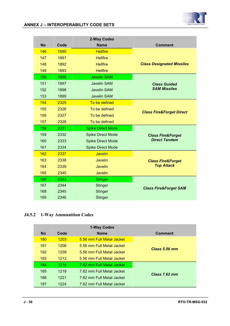
ANNEX J – INTEROPERABILITY CODE SETS
J - 36 RTO-TR-MSG-032
2-Way Codes No Code Name Comment 146 1890 Hellfire 147 1891 Hellfire 148 1892 Hellfire 149 1893 Hellfire
Class Designated Missiles
150 1896 Javelin SAM 151 1897 Javelin SAM 152 1898 Javelin SAM 153 1899 Javelin SAM
Class Guided SAM Missiles
154 2325 To be defined 155 2326 To be defined 156 2327 To be defined 157 2328 To be defined
Class Fire&Forget Direct
158 2331 Spike Direct Mode 159 2332 Spike Direct Mode 160 2333 Spike Direct Mode 161 2334 Spike Direct Mode
Class Fire&Forget Direct Tandem
162 2337 Javelin 163 2338 Javelin 164 2339 Javelin 165 2340 Javelin
Class Fire&Forget Top Attack
166 2343 Stinger 167 2344 Stinger 168 2345 Stinger 169 2346 Stinger
Class Fire&Forget SAM
J4.5.2 1-Way Ammunition Codes
1-Way Codes No Code Name Comment 180 1203 5.56 mm Full Metal Jacket 181 1206 5.56 mm Full Metal Jacket 182 1209 5.56 mm Full Metal Jacket 183 1212 5.56 mm Full Metal Jacket
Class 5.56 mm
184 1215 7.62 mm Full Metal Jacket 185 1218 7.62 mm Full Metal Jacket 186 1221 7.62 mm Full Metal Jacket 187 1224 7.62 mm Full Metal Jacket
Class 7.62 mm

ANNEX J – INTEROPERABILITY CODE SETS
RTO-TR-MSG-032 J - 37
1-Way Codes No Code Name Comment 188 1227 9 mm Full Metal Jacket 189 1230 9 mm Full Metal Jacket 190 1233 9 mm Full Metal Jacket
Class 9 mm
191 1236 12.7 mm Full Metal Jacket 192 1239 12.7 mm Full Metal Jacket 193 1242 12.7 mm Full Metal Jacket 194 1245 12.7 mm Full Metal Jacket
Class 12.7 mm
195 1248 ShotGun 196 1251 ShotGun 197 1254 ShotGun
Class ShotGun
198 1257 Small AP Mine 199 1260 Small AP Mine 200 1263 Small AP Mine 201 1266 Small AP Mine
Class AP Mines and Hand Grenades
202 1269 Small AT Mine 203 1272 Small AT Mine 204 1275 Small AT Mine 205 1278 Small AT Mine
Class AT Mines
206 1281 40 mm HE 207 1284 40 mm HE 208 1287 40 mm HE 209 1290 40 mm HE 210 1293 40 mm HE
Class 20 – 40 mm
211 1296 Laser Range Finder 212 1299 Laser Designator 213 1302 Indirect Hit Troop Transport 214 1305 Indirect Hit Back Blast 215 1307 Near Miss (Fine Calibre)
216 1310 Near Miss Heavy (Medium Calibre)
Class Special
217 2349 HE Vehicle 218 2352 7.62 – 12.7 mm 219 2355 HE ATW
Class 2-Way Fragments

ANNEX J – INTEROPERABILITY CODE SETS
J - 38 RTO-TR-MSG-032
RTO-TR-MSG-032 K - 1
Annex K – NEW TERMS OF REFERENCE AND TECHNICAL ACTIVITY PROGRAMME
TERMS OF REFERENCE
I. ORIGIN
A. Background NATO Studies SAS-030, Study on Urban Operations 2020 and Land Operations 2020 clearly indicate that Urban Areas are the most likely battlefield in the 21st century.
The problems and limitations associated with developing the first generation of Military Operations on Urban Terrain (MOUT) training facilities are only just beginning to be understood.
A team of experts from NATO NAAG completed a feasibility study in 2002. The conclusion was that a number of potential interoperability areas were identified and assessed to be worthy of further investigation.
TG-032 of NMSG started to identify and investigate some areas and reported them in their final report for the live domain. A number of areas were not completely covered or needed more investigation also a number of areas are new. Those new areas are in the constructive and the virtual domain. Also there is a need to further develop standards in laser and data communication, audio and visual effects.
To be done: Tables of Lethality and Vulnerability. A generic set of data for lethality and vulnerability is required to enable interoperability of nations’ simulation systems.
NATO’s FIBUA/MOUT Working Group and Topical Group 3 of the NAAG recognize the work done by the UCATT and endorse UCATT’s continuation to maintain and complete its work.
UCATT deliverables to date: Site register, Research needs, Interoperability specification, functional architecture and best practices.
In the last couple of years UCATT has become NATO’s focal point for MOUT training technology and exchanging information with the military community.
B. Military Benefit Operational Concepts: A comprehensive list of Generic User Requirements will be developed working in conjunction with NATO Training Groups and Military Users on the virtual and the constructive domain.
Standardization of frequency spectrum allocation and management, laser compatibility, battlefield effects simulations, firing through walls, indirect fires, tracking and position/location in built-up areas.
Extension of the live functional architecture for MOUT training to incorporate the virtual and constructive domains.
II. OBJECTIVES
Exchange and assess information on MOUT (live/constructive/virtual) installations and training/ simulation systems. Military feedback as to the effectiveness of current solutions will be obtained with a view toward establishing best practice.
ANNEX K – NEW TERMS OF REFERENCE AND TECHNICAL ACTIVITY PROGRAMME
K - 2 RTO-TR-MSG-032
Identify a suitable architecture and a standard set of interfaces that enable interoperability of MOUT Training components that does not inhibit future research and enhancements.
Identify limitations and constraints on MOUT development with a view toward identifying areas for future research.
Validate the applicability of JC3IEDM as the C4I standard for interfacing to the simulation environment.
Provide a standard for laser and data communication, audio and visual effects.
Organize an interoperability demonstration to prove the standards.
Define a generic set of data for lethality and vulnerability to enable interoperability of nations’ simulation systems.
III. RESOURCES
A. Membership Chair: Ing. Jan VERMEULEN, Netherlands.
B. Nations Really Participating Canada, Czech Republic, Finland, France, Germany, the Netherlands, Sweden, Switzerland, the United Kingdom and the United States.
IV. SECURITY LEVEL
The security level will be Unclassified/Unlimited.
V. PARTICIPATION BY PARTNER NATIONS AND OTHER NATIONS
This activity is open to PfP.
VI. LIAISON
VII. REFERENCE
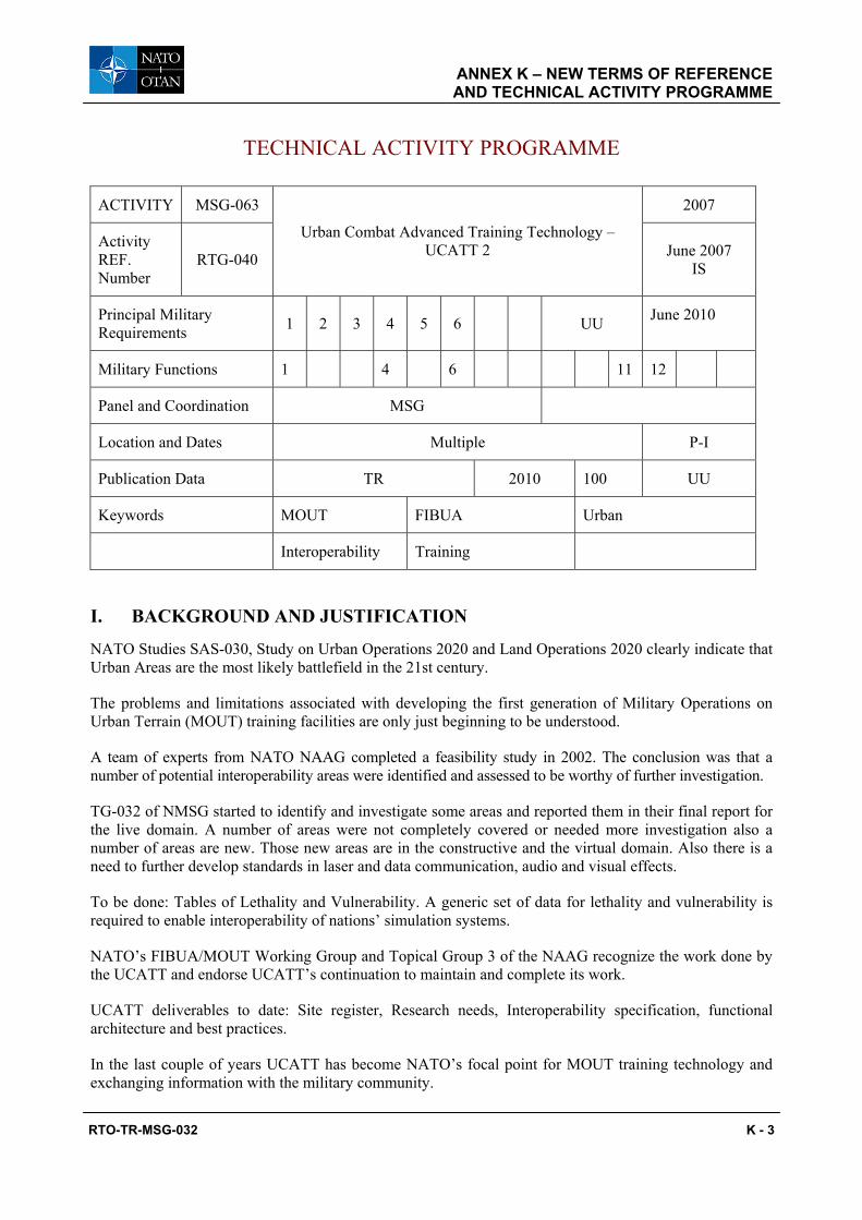
ANNEX K – NEW TERMS OF REFERENCE AND TECHNICAL ACTIVITY PROGRAMME
RTO-TR-MSG-032 K - 3
TECHNICAL ACTIVITY PROGRAMME
ACTIVITY MSG-063 2007
Activity REF. Number
RTG-040
Urban Combat Advanced Training Technology – UCATT 2 June 2007
IS
Principal Military Requirements 1 2 3 4 5 6 UU June 2010
Military Functions 1 4 6 11 12
Panel and Coordination MSG
Location and Dates Multiple P-I
Publication Data TR 2010 100 UU
Keywords MOUT FIBUA Urban
Interoperability Training
I. BACKGROUND AND JUSTIFICATION
NATO Studies SAS-030, Study on Urban Operations 2020 and Land Operations 2020 clearly indicate that Urban Areas are the most likely battlefield in the 21st century.
The problems and limitations associated with developing the first generation of Military Operations on Urban Terrain (MOUT) training facilities are only just beginning to be understood.
A team of experts from NATO NAAG completed a feasibility study in 2002. The conclusion was that a number of potential interoperability areas were identified and assessed to be worthy of further investigation.
TG-032 of NMSG started to identify and investigate some areas and reported them in their final report for the live domain. A number of areas were not completely covered or needed more investigation also a number of areas are new. Those new areas are in the constructive and the virtual domain. Also there is a need to further develop standards in laser and data communication, audio and visual effects.
To be done: Tables of Lethality and Vulnerability. A generic set of data for lethality and vulnerability is required to enable interoperability of nations’ simulation systems.
NATO’s FIBUA/MOUT Working Group and Topical Group 3 of the NAAG recognize the work done by the UCATT and endorse UCATT’s continuation to maintain and complete its work.
UCATT deliverables to date: Site register, Research needs, Interoperability specification, functional architecture and best practices.
In the last couple of years UCATT has become NATO’s focal point for MOUT training technology and exchanging information with the military community.

ANNEX K – NEW TERMS OF REFERENCE AND TECHNICAL ACTIVITY PROGRAMME
K - 4 RTO-TR-MSG-032
II. OBJECTIVE(S)
Exchange and assess information on MOUT (live/constructive/virtual) installations and training/ simulation systems. Military feedback as to the effectiveness of current solutions will be obtained with a view toward establishing best practice.
Identify a suitable architecture and a standard set of interfaces that enable interoperability of MOUT Training components that does not inhibit future research and enhancements.
Identify limitations and constraints on MOUT development with a view toward identifying areas for future research.
Validate the applicability of JC3IEDM as the C4I standard for interfacing to the simulation environment.
Provide a standard for laser and data communication, audio and visual effects.
Organize an interoperability demonstration to prove the standards.
Define a generic set of data for lethality and vulnerability to enable interoperability of nations’ simulation systems.
III. TOPICS TO BE COVERED
Operational Concepts: A comprehensive list of Generic User Requirements will be developed working in conjunction with NATO Training Groups and Military Users on the virtual and the constructive domain.
Standardization of frequency spectrum allocation and management, laser compatibility, battlefield effects simulations, firing through walls, indirect fires, tracking and position/location in built-up areas.
Extension of the live functional architecture for MOUT training to incorporate the virtual and constructive domains.
IV. DELIVERABLE
Technical Report.
V. TECHNICAL TEAM LEADER AND LEAD NATION
Chair: Ing. Jan VERMEULEN, Netherlands.
Lead Nation: Netherlands.
VI. NATIONS WILLING/INVITED TO PARTICIPATE
Canada, Czech Republic, Finland, France, Germany, the Netherlands, Sweden, Switzerland, the United Kingdom and the United States.
VII. NATIONAL AND/OR NATO RESOURCES NEEDED
Travel funding for national participation in meetings.

ANNEX K – NEW TERMS OF REFERENCE AND TECHNICAL ACTIVITY PROGRAMME
RTO-TR-MSG-032 K - 5
VIII. RTA RESOURCES NEEDED
MSCO support to TG.
Publication.

ANNEX K – NEW TERMS OF REFERENCE AND TECHNICAL ACTIVITY PROGRAMME
K - 6 RTO-TR-MSG-032

RTO-TR-MSG-032
REPORT DOCUMENTATION PAGE
1. Recipient’s Reference 2. Originator’s References 3. Further Reference
4. Security Classificationof Document
RTO-TR-MSG-032 AC/323(MSG-032)TP/293
ISBN 978-92-837-0098-2
UNCLASSIFIED/ UNLIMITED
5. Originator Research and Technology Organisation North Atlantic Treaty Organisation BP 25, F-92201 Neuilly-sur-Seine Cedex, France
6. Title Urban Combat Advanced Training Technology
7. Presented at/Sponsored by
Final Report of Task Group 032.
8. Author(s)/Editor(s) 9. Date
Multiple April 2010
10. Author’s/Editor’s Address 11. Pages
Multiple 206
12. Distribution Statement
There are no restrictions on the distribution of this document. Information about the availability of this and other RTO unclassified publications is given on the back cover.
13. Keywords/Descriptors
Combat Training Centre (CTC) Direct Fire Weapon Effects System (DFWES) Interoperability Simulation
14. Abstract
The Urban Combat Advanced Training Technology (UCATT) Task Group (TG) was established within the NATO Modelling and Simulation Group (NMSG) in 2003 as MSG-032 TG-023. The UCATT TG was tasked to exchange and assess information on Military Operations in Urban Terrain (MOUT) facilities and training/simulation systems with a view toward establishing best practice. In addition it was required to identify a suitable architecture and a standard set of interfaces that would enable interoperability of MOUT training components without inhibiting future enhancements, and pinpoint limitations and constraints on MOUT development so that areas for future research could be identified. The end product of this TG is this comprehensive report detailing an architectural framework to enable interoperability and future research requirements for MOUT training facilities. This report covers the work of UCATT from its inception and the work conducted to date which includes the development of a MOUT website and architectural framework based on USE CASES and an analysis of the functional components mapped to national requirements for live force-on-force urban training.

RTO-TR-MSG-032

NORTH ATLANTIC TREATY ORGANISATION RESEARCH AND TECHNOLOGY ORGANISATION
BP 25
F-92201 NEUILLY-SUR-SEINE CEDEX • FRANCE Télécopie 0(1)55.61.22.99 • E-mail [email protected]
DIFFUSION DES PUBLICATIONS
RTO NON CLASSIFIEES
Les publications de l’AGARD et de la RTO peuvent parfois être obtenues auprès des centres nationaux de distribution indiqués ci-dessous. Si vous souhaitez recevoir toutes les publications de la RTO, ou simplement celles qui concernent certains Panels, vous pouvez demander d’être inclus soit à titre personnel, soit au nom de votre organisation, sur la liste d’envoi. Les publications de la RTO et de l’AGARD sont également en vente auprès des agences de vente indiquées ci-dessous. Les demandes de documents RTO ou AGARD doivent comporter la dénomination « RTO » ou « AGARD » selon le cas, suivi du numéro de série. Des informations analogues, telles que le titre est la date de publication sont souhaitables. Si vous souhaitez recevoir une notification électronique de la disponibilité des rapports de la RTO au fur et à mesure de leur publication, vous pouvez consulter notre site Web (www.rto.nato.int) et vous abonner à ce service.
CENTRES DE DIFFUSION NATIONAUX
ALLEMAGNE HONGRIE REPUBLIQUE TCHEQUE Streitkräfteamt / Abteilung III Department for Scientific Analysis LOM PRAHA s. p. Fachinformationszentrum der Bundeswehr (FIZBw) Institute of Military Technology o. z. VTÚLaPVO Gorch-Fock-Straße 7, D-53229 Bonn Ministry of Defence Mladoboleslavská 944 P O Box 26 PO Box 18
BELGIQUE H-1525 Budapest 197 21 Praha 9 Royal High Institute for Defence – KHID/IRSD/RHID Management of Scientific & Technological Research ITALIE ROUMANIE
for Defence, National RTO Coordinator General Secretariat of Defence and Romanian National Distribution Royal Military Academy – Campus Renaissance National Armaments Directorate Centre Renaissancelaan 30, 1000 Bruxelles 5th Department – Technological Armaments Department Research 9-11, Drumul Taberei Street
CANADA Via XX Settembre 123 Sector 6 DSIGRD2 – Bibliothécaire des ressources du savoir 00187 Roma 061353, Bucharest R et D pour la défense Canada Ministère de la Défense nationale LUXEMBOURG ROYAUME-UNI 305, rue Rideau, 9e étage Voir Belgique Dstl Knowledge and Information Ottawa, Ontario K1A 0K2 Services
NORVEGE Building 247 DANEMARK Norwegian Defence Research Porton Down
Danish Acquisition and Logistics Organization (DALO) Establishment Salisbury SP4 0JQ Lautrupbjerg 1-5, 2750 Ballerup Attn: Biblioteket P.O. Box 25 SLOVAQUIE
ESPAGNE NO-2007 Kjeller Akadémia ozbrojených síl SDG TECEN / DGAM M.R. Štefánika, Distribučné a C/ Arturo Soria 289 PAYS-BAS informačné stredisko RTO Madrid 28033 Royal Netherlands Military Demanova 393, P.O.Box 45
Academy Library 031 19 Liptovský Mikuláš ETATS-UNIS P.O. Box 90.002
NASA Center for AeroSpace Information (CASI) 4800 PA Breda SLOVENIE 7115 Standard Drive Ministry of Defence Hanover, MD 21076-1320 POLOGNE Central Registry for EU and Centralna Biblioteka Wojskowa NATO
FRANCE ul. Ostrobramska 109 Vojkova 55 O.N.E.R.A. (ISP) 04-041 Warszawa 1000 Ljubljana 29, Avenue de la Division Leclerc BP 72, 92322 Châtillon Cedex PORTUGAL TURQUIE Estado Maior da Força Aérea Milli Savunma Bakanlığı (MSB)
GRECE (Correspondant) SDFA – Centro de Documentação ARGE ve Teknoloji Dairesi Defence Industry & Research General Alfragide Başkanlığı
Directorate, Research Directorate P-2720 Amadora 06650 Bakanliklar Fakinos Base Camp, S.T.G. 1020 Ankara Holargos, Athens
AGENCES DE VENTE NASA Center for AeroSpace The British Library Document Canada Institute for Scientific and
Information (CASI) Supply Centre Technical Information (CISTI) 7115 Standard Drive Boston Spa, Wetherby National Research Council Acquisitions Hanover, MD 21076-1320 West Yorkshire LS23 7BQ Montreal Road, Building M-55 ETATS-UNIS ROYAUME-UNI Ottawa K1A 0S2, CANADA Les demandes de documents RTO ou AGARD doivent comporter la dénomination « RTO » ou « AGARD » selon le cas, suivie du numéro de série (par exemple AGARD-AG-315). Des informations analogues, telles que le titre et la date de publication sont souhaitables. Des références bibliographiques complètes ainsi que des résumés des publications RTO et AGARD figurent dans les journaux suivants :
Scientific and Technical Aerospace Reports (STAR) Government Reports Announcements & Index (GRA&I) STAR peut être consulté en ligne au localisateur de ressources publié par le National Technical Information Service uniformes (URL) suivant: http://www.sti.nasa.gov/Pubs/star/Star.html Springfield STAR est édité par CASI dans le cadre du programme Virginia 2216 NASA d’information scientifique et technique (STI) ETATS-UNIS STI Program Office, MS 157A (accessible également en mode interactif dans la base de NASA Langley Research Center données bibliographiques en ligne du NTIS, et sur CD-ROM) Hampton, Virginia 23681-0001 ETATS-UNIS

NORTH ATLANTIC TREATY ORGANISATION RESEARCH AND TECHNOLOGY ORGANISATION
BP 25
F-92201 NEUILLY-SUR-SEINE CEDEX • FRANCE Télécopie 0(1)55.61.22.99 • E-mail [email protected]
DISTRIBUTION OF UNCLASSIFIED RTO PUBLICATIONS
AGARD & RTO publications are sometimes available from the National Distribution Centres listed below. If you wish to receive all RTO reports, or just those relating to one or more specific RTO Panels, they may be willing to include you (or your Organisation) in their distribution. RTO and AGARD reports may also be purchased from the Sales Agencies listed below. Requests for RTO or AGARD documents should include the word ‘RTO’ or ‘AGARD’, as appropriate, followed by the serial number. Collateral information such as title and publication date is desirable. If you wish to receive electronic notification of RTO reports as they are published, please visit our website (www.rto.nato.int) from where you can register for this service.
NATIONAL DISTRIBUTION CENTRES BELGIUM HUNGARY ROMANIA
Royal High Institute for Defence – KHID/IRSD/RHID Department for Scientific Analysis Romanian National Distribution Management of Scientific & Technological Research Institute of Military Technology Centre
for Defence, National RTO Coordinator Ministry of Defence Armaments Department Royal Military Academy – Campus Renaissance P O Box 26 9-11, Drumul Taberei Street Renaissancelaan 30 H-1525 Budapest Sector 6, 061353, Bucharest 1000 Brussels
ITALY SLOVAKIA CANADA General Secretariat of Defence and Akadémia ozbrojených síl
DRDKIM2 – Knowledge Resources Librarian National Armaments Directorate M.R. Štefánika, Distribučné a Defence R&D Canada 5th Department – Technological informačné stredisko RTO Department of National Defence Research Demanova 393, P.O.Box 45 305 Rideau Street, 9th Floor Via XX Settembre 123 031 19 Liptovský Mikuláš Ottawa, Ontario K1A 0K2 00187 Roma
SLOVENIA CZECH REPUBLIC LUXEMBOURG Ministry of Defence
LOM PRAHA s. p. See Belgium Central Registry for EU & NATO o. z. VTÚLaPVO Vojkova 55 Mladoboleslavská 944 NETHERLANDS 1000 Ljubljana PO Box 18 Royal Netherlands Military 197 21 Praha 9 Academy Library SPAIN
P.O. Box 90.002 SDG TECEN / DGAM DENMARK 4800 PA Breda C/ Arturo Soria 289
Danish Acquisition and Logistics Organization (DALO) Madrid 28033 Lautrupbjerg 1-5 NORWAY 2750 Ballerup Norwegian Defence Research TURKEY Establishment Milli Savunma Bakanlığı (MSB)
FRANCE Attn: Biblioteket ARGE ve Teknoloji Dairesi O.N.E.R.A. (ISP) P.O. Box 25 Başkanlığı 29, Avenue de la Division Leclerc NO-2007 Kjeller 06650 Bakanliklar – Ankara BP 72, 92322 Châtillon Cedex POLAND UNITED KINGDOM
GERMANY Centralna Biblioteka Wojskowa Dstl Knowledge and Information Streitkräfteamt / Abteilung III ul. Ostrobramska 109 Services Fachinformationszentrum der Bundeswehr (FIZBw) 04-041 Warszawa Building 247 Gorch-Fock-Straße 7 Porton Down D-53229 Bonn PORTUGAL Salisbury SP4 0JQ Estado Maior da Força Aérea
GREECE (Point of Contact) SDFA – Centro de Documentação UNITED STATES Defence Industry & Research General Directorate Alfragide NASA Center for AeroSpace Research Directorate, Fakinos Base Camp P-2720 Amadora Information (CASI) S.T.G. 1020 7115 Standard Drive Holargos, Athens Hanover, MD 21076-1320
SALES AGENCIES NASA Center for AeroSpace The British Library Document Canada Institute for Scientific and
Information (CASI) Supply Centre Technical Information (CISTI) 7115 Standard Drive Boston Spa, Wetherby National Research Council Acquisitions Hanover, MD 21076-1320 West Yorkshire LS23 7BQ Montreal Road, Building M-55 UNITED STATES UNITED KINGDOM Ottawa K1A 0S2, CANADA Requests for RTO or AGARD documents should include the word ‘RTO’ or ‘AGARD’, as appropriate, followed by the serial number (for example AGARD-AG-315). Collateral information such as title and publication date is desirable. Full bibliographical references and abstracts of RTO and AGARD publications are given in the following journals:
Scientific and Technical Aerospace Reports (STAR) Government Reports Announcements & Index (GRA&I) STAR is available on-line at the following uniform resource published by the National Technical Information Service locator: http://www.sti.nasa.gov/Pubs/star/Star.html Springfield STAR is published by CASI for the NASA Scientific Virginia 2216 and Technical Information (STI) Program UNITED STATES STI Program Office, MS 157A (also available online in the NTIS Bibliographic Database NASA Langley Research Center or on CD-ROM) Hampton, Virginia 23681-0001 UNITED STATES
ISBN 978-92-837-0098-2


![Graph-Based Analysis of Human Transfer Learning …ailab.wsu.edu/uct/papers/CookTKDE07.pdf2. Urban Combat To support our study, we have developed the Urban Combat Testbed (UCT) [39]](https://img.dokumen.tips/doc/110x75/5fc411eefaea5f03f07048ec/graph-based-analysis-of-human-transfer-learning-ailabwsueduuctpapers-2-urban.jpg)