Embed Size (px)
Citation preview

URBAN BEST MANAGEMENT
PRACTICES
FOR NONPOINT SOURCE POLLUTION
Produced by the
Point and Nonpoint Source Programs
Water Quality Division
Wyoming Department of Environmental Quality
September 1999


i
TABLE OF CONTENTS
PURPOSE . . . . . . . . . . . . . . . . . . . . . . . . . . . . . . . . . . . . . . . . . . . . . . . . . . . . . . . . . . . . . . . . . . . . . . . . . . . . . . . . . . i
ACKNOWLEDGMENTS . . . . . . . . . . . . . . . . . . . . . . . . . . . . . . . . . . . . . . . . . . . . . . . . . . . . . . . . . . . . . . . . . . . . . . i
INTRODUCTION . . . . . . . . . . . . . . . . . . . . . . . . . . . . . . . . . . . . . . . . . . . . . . . . . . . . . . . . . . . . . . . . . . . . . . . . . . . 1
URBAN BMP LIST . . . . . . . . . . . . . . . . . . . . . . . . . . . . . . . . . . . . . . . . . . . . . . . . . . . . . . . . . . . . . . . . . . . . . . . . . . 7RUNOFF FROM CONSTRUCTION SITES . . . . . . . . . . . . . . . . . . . . . . . . . . . . . . . . . . . . . . . . . . . . . . . 8RUNOFF FROM EXISTING DEVELOPMENT . . . . . . . . . . . . . . . . . . . . . . . . . . . . . . . . . . . . . . . . . . . . 9RUNOFF FROM DEVELOPING AREAS . . . . . . . . . . . . . . . . . . . . . . . . . . . . . . . . . . . . . . . . . . . . . . . . 10GENERAL SOURCES (HOUSEHOLD, COMMERCIAL, AND LANDSCAPING) . . . . . . . . . . . . . . 11ROADS, HIGHWAYS, AND BRIDGES . . . . . . . . . . . . . . . . . . . . . . . . . . . . . . . . . . . . . . . . . . . . . . . . . 12WATERSHED PROTECTION . . . . . . . . . . . . . . . . . . . . . . . . . . . . . . . . . . . . . . . . . . . . . . . . . . . . . . . . . 13
FACT SHEETS FOR URBAN BEST MANAGEMENT PRACTICES . . . . . . . . . . . . . . . . . . . . . . . . . . . . . . . . 14
DIRECT MANAGEMENT PRACTICES . . . . . . . . . . . . . . . . . . . . . . . . . . . . . . . . . . . . . . . . . . . . . . . . . . . . . . . . 15EXTENDED DETENTION PONDS . . . . . . . . . . . . . . . . . . . . . . . . . . . . . . . . . . . . . . . . . . . . . . . . . . . . 16WET PONDS . . . . . . . . . . . . . . . . . . . . . . . . . . . . . . . . . . . . . . . . . . . . . . . . . . . . . . . . . . . . . . . . . . . . . . 20STORM WATER WETLANDS . . . . . . . . . . . . . . . . . . . . . . . . . . . . . . . . . . . . . . . . . . . . . . . . . . . . . . . . 24MULTIPLE POND SYSTEMS . . . . . . . . . . . . . . . . . . . . . . . . . . . . . . . . . . . . . . . . . . . . . . . . . . . . . . . . . 29INFILTRATION TRENCHES . . . . . . . . . . . . . . . . . . . . . . . . . . . . . . . . . . . . . . . . . . . . . . . . . . . . . . . . . 34INFILTRATION BASINS . . . . . . . . . . . . . . . . . . . . . . . . . . . . . . . . . . . . . . . . . . . . . . . . . . . . . . . . . . . . 39POROUS PAVEMENT . . . . . . . . . . . . . . . . . . . . . . . . . . . . . . . . . . . . . . . . . . . . . . . . . . . . . . . . . . . . . . . 44CONCRETE GRID PAVEMENT . . . . . . . . . . . . . . . . . . . . . . . . . . . . . . . . . . . . . . . . . . . . . . . . . . . . . . . 48SAND FILTERS . . . . . . . . . . . . . . . . . . . . . . . . . . . . . . . . . . . . . . . . . . . . . . . . . . . . . . . . . . . . . . . . . . . . 51GRASSED SWALES . . . . . . . . . . . . . . . . . . . . . . . . . . . . . . . . . . . . . . . . . . . . . . . . . . . . . . . . . . . . . . . . 55FILTER STRIPS . . . . . . . . . . . . . . . . . . . . . . . . . . . . . . . . . . . . . . . . . . . . . . . . . . . . . . . . . . . . . . . . . . . . 61SEDIMENT TRAPS . . . . . . . . . . . . . . . . . . . . . . . . . . . . . . . . . . . . . . . . . . . . . . . . . . . . . . . . . . . . . . . . . 66WIND EROSION CONTROLS . . . . . . . . . . . . . . . . . . . . . . . . . . . . . . . . . . . . . . . . . . . . . . . . . . . . . . . . 69CHECK DAMS-SILT FENCE . . . . . . . . . . . . . . . . . . . . . . . . . . . . . . . . . . . . . . . . . . . . . . . . . . . . . . . . . 71STEEP SLOPE DIVERSION TERRACES . . . . . . . . . . . . . . . . . . . . . . . . . . . . . . . . . . . . . . . . . . . . . . . 75WATER QUALITY INLETS/ OIL-WATER SEPARATORS . . . . . . . . . . . . . . . . . . . . . . . . . . . . . . . . . 77STREAMBANK STABILIZATION . . . . . . . . . . . . . . . . . . . . . . . . . . . . . . . . . . . . . . . . . . . . . . . . . . . . 81MISCELLANEOUS BMPs FOR URBAN CONSTRUCTION . . . . . . . . . . . . . . . . . . . . . . . . . . . . . . . . 85
INDIRECT MANAGEMENT PRACTICES . . . . . . . . . . . . . . . . . . . . . . . . . . . . . . . . . . . . . . . . . . . . . . . . . . . . . 93DIRECT RUNOFF AWAY FROM NATURAL CHANNELS . . . . . . . . . . . . . . . . . . . . . . . . . . . . . . . . 94PROPER DISPOSAL OF ACCUMULATED SEDIMENT . . . . . . . . . . . . . . . . . . . . . . . . . . . . . . . . . . . 95PROPER SNOW REMOVAL AND STORAGE . . . . . . . . . . . . . . . . . . . . . . . . . . . . . . . . . . . . . . . . . . . 96HERBICIDE/PESTICIDE/FERTILIZER MANAGEMENT . . . . . . . . . . . . . . . . . . . . . . . . . . . . . . . . . . 97PROTECT NATURAL AND RIPARIAN VEGETATION . . . . . . . . . . . . . . . . . . . . . . . . . . . . . . . . . 98RECYCLING . . . . . . . . . . . . . . . . . . . . . . . . . . . . . . . . . . . . . . . . . . . . . . . . . . . . . . . . . . . . . . . . . . . . . . 99LITTER REMOVAL . . . . . . . . . . . . . . . . . . . . . . . . . . . . . . . . . . . . . . . . . . . . . . . . . . . . . . . . . . . . . . . . 100STREET SWEEPING . . . . . . . . . . . . . . . . . . . . . . . . . . . . . . . . . . . . . . . . . . . . . . . . . . . . . . . . . . . . . . . 101EXPOSURE REDUCTION . . . . . . . . . . . . . . . . . . . . . . . . . . . . . . . . . . . . . . . . . . . . . . . . . . . . . . . . . . 102EDUCATION . . . . . . . . . . . . . . . . . . . . . . . . . . . . . . . . . . . . . . . . . . . . . . . . . . . . . . . . . . . . . . . . . . . . . 103
APPENDIX A . . . . . . . . . . . . . . . . . . . . . . . . . . . . . . . . . . . . . . . . . . . . . . . . . . . . . . . . . . . . . . . . . . . . . . . . . . . . 105
GLOSSARY . . . . . . . . . . . . . . . . . . . . . . . . . . . . . . . . . . . . . . . . . . . . . . . . . . . . . . . . . . . . . . . . . . . . . . . . . . . . . 121
REFERENCES CITED . . . . . . . . . . . . . . . . . . . . . . . . . . . . . . . . . . . . . . . . . . . . . . . . . . . . . . . . . . . . . . . . . . . . . 130

i
PURPOSE
This "Best Management Practices" document is designed to provide a series of conservationpractices. This document can be used as a guide for municipalities, private individuals andindustries who are conducting day to day management activities in urban or suburban situations. When selected and applied properly, these urban best management practices (BMPs) will resultin maintaining the existing beneficial uses of water resources and reducing adverse effects andwater quality degradation. It is also being prepared as part of the "Wyoming Nonpoint SourceManagement Plan" as required by section 319(b) of the Clean Water Act.
Not all urban BMPs can remove both particulate and soluble pollutants. The choice of aparticular BMP or series of BMPs depends on many factors. The quantity of storm water, typesof pollutants expected, site location (residential, commercial, industrial), site topography, landcosts, installation costs, and maintenance requirements will all affect BMP selection.
Several fundamental uncertainties still exist with respect to urban BMPs, including toxicity ofresiduals trapped by the practice; the interaction of groundwater with BMPs, and the long-termBMP performance.
This report is a compilation of information on several structural and non-structural BMPs. Specific BMPs may or may not be appropriate for a particular site or situation. Some of theBMPs discussed in this text may require design and construction oversight by a professionalengineer. Permits may also be required from local, state or federal government for some types ofBMPs. Be certain to check with appropriate agencies during the planning process to determinepermit requirements. Thorough research, planning, and design should go into the selection andinstallation of any storm water BMP.
ACKNOWLEDGMENTS
A large part of this document is adapted from a publication from the Metropolitan WashingtonCouncil of Governments; A Current Assessment of Urban Best Management Practices:Techniques for Reducing Nonpoint Source Pollution in the Coastal Zone (Schueler, T.R., et al.,1992, 127 pp.).
The section on Miscellaneous BMPs for Urban Construction (BMP #18) is based, in large part,on a recent publication from the Denver Regional Council of Governments (DRCOG); KeepingSoil on Site: Construction Best Management Practices (1998, 76 pp.). The Nonpoint SourceTask Force found this publication very helpful and relevant to conditions in Wyoming.

1
INTRODUCTION
Nonpoint source pollution (NPS) is generally considered to be a diffuse source of pollution notassociated with a specific point of entry into the water body. Point sources are defined as anydiscernible, confined, and discrete conveyance from which pollutants are or may be discharged. Urban runoff is unique, in that most of the sources are the result of nonpoint influences. However, the conveyances to the surface waters are generally point sources.
Nonpoint sources of pollution include sediment from small construction sites, metals and othercontaminants washed from streets and/or fertilizers or pesticides washing from lawns. Therunoff becomes a point source because storm sewers, which are not connected to wastewatertreatment plants, collect the runoff and convey it to surface waters.
Urban centers in Wyoming are typically located near surface water. In most cases, there are oneor more streams flowing through our cities. Protecting these streams is a major challenge andbecomes more critical as cities experience population increases.
Table 1 lists pollutants typically found in urban runoff. Runoff constituents specific to highwaysare listed in Table 2. Considerable effort has gone into identifying constituents in urban runoff,which can degrade the quality of surface and ground water. Agencies from several areas of thecountry have put significant time and resources into identifying the pathways by which thesepollutants enter surface or ground water. For information on urban runoff in semi-aridenvironments, data from recent runoff studies in the Denver Metropolitan area have beenincluded in Table 3.
Urban pollution presents some difficult problems. Pollutants accumulate during the timebetween rainfall events or before snowbelt. When rain falls or snow melts in the urbanenvironment there is a sudden introduction of pollutants into lakes, rivers, wetlands, andgroundwater; commonly known as the first flush effect.
The Wyoming Water Quality Division (WQD) Watershed Management Nonpoint SourceProgram is committed to working with local governments to assist in identifying water qualityproblems and implementing workable, cost effective solutions. To achieve this end, theWyoming Nonpoint Source Task Force has compiled documentation on the following BMPs. For further information, a list of references is also included at the end of this document. Inaddition to government and academic sources, much information can be obtained on the internet. Some web sites are included in the reference section and more are available on the World WideWeb.
These practices are grouped under broad Categories which address a particular group of potentialpollutant sources. Each Category reflects the greatest degree of pollutant reduction achievablethrough the application of a series of best management practices. The BMPs reflect the best

2
control practices, technologies, processes, and operating methods available to address nonpointsource pollution problems in our cities.
Much of the research on urban BMPs has occurred on the east and west coasts in climateconditions that may not be applicable to Wyoming. However, Wyoming has a great diversity oflocal climates and each of these BMPs should be effective in at least some areas of the state. When evaluating a specific BMP consideration should be given to climate, as well as location,flow, expected pollutants, and maintenance requirements. Installing more than one practice in“series” may overcome the drawbacks of any single method, while providing enhanced pollutantremoval.
One BMP that is critical to improving urban storm water quality is public education. Manyurban residents are not aware that storm sewers do not carry runoff to treatment plants, but ratherdirectly to nearby rivers. Residents should also understand that while the actions of a singleperson may seem insignificant, when combined with similar actions of hundreds or thousands ofother residents, the potential to pollute their local waters is very real. The quart of oil dumpeddown a storm drain by one person on a given Saturday may be repeated hundreds of times thatday.
Local development plans, ordinances and regulations may also play a role. Plans or regulationsmay encourage or mandate set backs from water bodies, treatment of runoff from constructionsites or impervious areas, or percent allowable impervious area on a given lot size. Zoningrequirements may be modified, if necessary, to allow residential development styles that reduceimpervious areas and increase green space.
Existing Storm Water Regulations
In 1987 the United States Congress amended the federal Clean Water Act to include theregulation of some sources of storm water. The US Environmental Protection Agency (EPA)published regulations governing storm water discharges in 1990. In 1991, EPA granted theWyoming Department of Environmental Quality (DEQ) primacy for the storm water program inWyoming. DEQ primarily administers the program through two general permits, one for specifictypes of industrial activities defined in the federal regulations and the other for constructionprojects that clear or grade five or more acres. Under federal regulations storm water fromcovered sources is generally considered a “point source” whether or not it enters a storm sewer.
At this time, Wyoming has no municipalities required to obtain a storm water permit. Underexisting regulations only those cities with a population of 100,000 or more are covered. Revisions to the storm water regulations, known as Storm Water Phase II, will include“urbanized areas” with populations of 50,000 or more. The urbanized areas will include Casperand Cheyenne and their surrounding developed areas in the county and nearby by towns such asMills and Evansville near Casper. DEQ will also be required to evaluate cities with populationsbetween 10,000 and 50,000 (Evanston, Gillette, Green River, Laramie, Rock Springs, Sheridan

3
and their surrounding developed areas) for possible inclusion in the storm water permit program. A change for all Wyoming municipalities is the end of the municipal exemption for city or townowned industrial facilities such as maintenance garages. The incorporation of BMPs into theurban/suburban setting will become increasingly important as the changes associated with StormWater Phase II begin to affect municipalities in Wyoming.
The precise requirements for municipal permits under the new regulations are not know at thistime. The Storm Water Phase II regulations are expected to be published in 1999 and shouldbegin to be implemented about three years later.
The size of construction projects covered under storm water regulations is also expected todecrease from a five acre minimum to one acre. Many urban/suburban construction projects thatare not now required to obtain coverage will fall under the revised storm water regulations. These changes are expected to take effect about three years after final rule publication whichshould be in 2002.

4
Table 1 - Pollutants Typically Found in Urban Runoff *
COMMONURBAN RUNOFF
POLLUTANTSOURCE
AVERAGECONCENTRATE NONPOINT SOURCE IMPACTS
Sediment Urban/Suburban
80 mg/lAverage
Fills in ponds and reservoirs with mud; contributes to decline of submergentaquatic vegetation by increasing turbidity and reducing the light available forphotosynthesis, and covers or reduces spawning beds.. Acts as a sink fornutrients and toxicants and as a source when disturbed and resuspended.
TotalPhosphorus
Urban/Suburban
1.08 mg/l0.26 mg/l
A contributing factor cited in eutrophication (nutrient over-enrichment) inreceiving water bodies and subsequent algal blooms. Algal blooms contribute tothe decline of submerged aquatic vegetation by reducing light available forphotosynthesis, further degrade water quality by decreasing the level of dissolvedoxygen (DO), increase Biological Oxygen Demand (BOD), and may causechanges in the composition of plankton and fish species.
Total Nitrogen Urban/Suburban
13.6 mg/l2.00 mg/l
Like total phosphorus, contributes to eutrophication and algal blooms, thoughmore typically in salt water bodies.
ChemicalOxygenDemand(COD)
Urban/Suburban
163.0 mg/l35.6 mg/l
Decreases the concentration of dissolved oxygen (DO). Low DO concentrationand anaerobic conditions (complete absence of DO) can lead to fish kills andunpleasant odors. Primarily released as organic matter in the "first flush" ofurban runoff after storm.
Bacteria Urban/Suburban
Avg.-200 to240,000 MPN/L
High concentrations can lead to aquifer contamination and closure of shellfishharvesting areas and prevent swimming, boating, or other recreational activities.
Zinc Urban/Suburban
0.397 mg/l0.037 mg/l
Chronically exceeds EPA water quality criteria. Many fish species highlysensitive to zinc. Primary cultural source is the weathering and abrasion ofgalvanized iron and steel.
Copper Urban/Suburban
0.105 mg/l0.047 mg/l(Nationwide Avg.)
Chronically exceeds EPA water quality criteria. Primary cultural source is as acomponent of anti-fouling paint for boat hulls and in urban runoff, from theleaching and abrasion of copper pipes and brass fittings. An important tracenutrient, it can bioaccumulate, and thereby, create toxic health hazards withinthe food chain and increase long term ecosystem stress.
Lead Urban/Suburban
0.389 mg/l0.018 mg/l
Lead from gasoline burning in automobiles is less of a problem today because ofunleaded gasoline use. However, lead from scraping and painting bridges andoverpasses remains. Chronically exceeds EPA water quality criteria. Attachesreadily to fine particles that can be bioaccumulated by bacteria and benthicorganisms while feeding. Lead has adverse health impacts when consumed byhumans.
Oil and Grease Urban/Suburban
Avg. 2-10 mg/l Toxicity contributes to the decline of zooplankton and benthic organisms.Accumulates in the tissues of benthic organisms; a threat to humans whenconsumed directly or when passed through the food chain. Primary culturalsource is automobile oil and lubricants.
Arsenic Urban/Suburban
Avg. 6.0 Fg/l An essential trace nutrient. Can be bioaccumulated; creates toxic health hazardswithin the food chain and increases long term stress for the ecosystem. Accumulates within tidal, freshwater areas, increasing the toxicity for spawningand juvenile fish. Primary cultural source is fossil fuel combustion.
Cadmium Urban/Suburban
Avg. 1.0 Fg/l Primary cultural source is metal electroplating and pigments in paint. Can bebioaccumulated; creates toxic health hazards within the food chain and increaseslong-term toxic stress for the ecosystem.
Chromium Urban/Suburban
Avg. 5.0Fg/l Primary cultural source is metal electroplating and pigments in paint. Can bebioaccumulated; creates toxic health hazards within the food chain and increaseslong-term toxic stress for the ecosystem.
Pesticides Urban/Suburban
Avg. <0.1 Fg/l Primary urban source is runoff from home gardens and lawns. Canbioaccumulate in organisms and create toxic health hazards within the foodchain. Also has been found as a contaminant in aquifers.
*Based on mid-Atlantic Coast data. Source: Metropolitan Washington Council of Governments, 1993 (as described in TerreneInstitute, 1994).

5
Table 2Highway Runoff Constituents and Their Primary Sources
Constituents Primary Sources
Particulates Pavement wear, vehicles, atmosphere, maintenance
Nitrogen, Phosphorus Atmosphere, roadside fertilizer application
Lead Leaded gasoline (auto exhaust), tire wear (lead oxide filler material,lubricating oil and grease, bearing wear)
Zinc Tire wear (filler material), motor oil (stabilizing additive), grease
Iron Auto body rust, steel highway structures (guard rails, bridges, etc.),moving engine parts
Copper Metal plating, bearing and brush wear, moving engine parts, brakelining wear, fungicides and insecticides
Cadmium Tire wear (filler material), insecticide application
Chromium Metal plating, moving engine parts, brake lining wear
Nickel Diesel fuel and gasoline (exhaust), lubricating oil, metal plating,bushing wear, brake lining wear, asphalt paving
Manganese Moving engine parts
Cyanide Anti-cake compounds (ferric ferrocyanide, sodium ferrocyanide,yellow prussiate of soda) used to keep deicing salt granular
Sodium, Calcium,Chloride
Deicing salts
Sulphate Roadway beds, fuel, deicing salts
Petroleum Spills, leaks or blow-by of motor lubricants, antifreeze and hydraulicfluids, asphalt surface leachate

6
Table 3Storm Water Runoff Constituents, Denver Metropolitan Area and National Data
Parameter Denver Metro-Industrial EMC*
Denver Metro-CommercialEMC*
Denver Metro-ResidentialEMC*
NURP - Medianfor Urban Sites
TotalPhosphorus
0.43 mg/l 0.34 mg/l 0.87 mg/l 0.33 mg/l
Total Nitrogen 2.7 mg/l 3.9 mg/l 4.7 mg/l 2.2 mg/l
ChemicalOxygen Demand(COD)
232 mg/l 173 mg/l 95 mg/l 65 mg/l
Total Zinc 0.520 mg/l 0.294 mg/l 0.182 mg/l 0.160 mg/l
Total Copper 0.084 mg/l 0.081 mg/l 0.031 mg/l 0.034 mg/l
Total Lead 0.128 mg/l 0.059 mg/l 0.053 mg/l 0.144 mg/l
Data from Nationwide Urban Runoff Program (NURP) conducted 1978-1982 and from urbanrunoff monitoring conducted by Denver, Lakewood, and Aurora, CO in the early 1990s.*EMC = Even Mean Concentration

7
URBAN BMP LIST
(Direct control practices and indirect prevention practices)
The following is a list of the practices included in this manual. Direct management practices areusually structural practices installed for the purposed of treating contaminated storm water. Indirect management practices are often non-structural methods that focus on pollutant reductionat the source or the use of existing natural features, such as vegetation, to reduce pollutants instorm water runoff.
Most practices work best with a specific type of pollutant, for example sediments or dissolvedmetals. When considering a practice or group of practices for a site the decision on whatpractices to adopt will depend on many factors including the pollutants to be removed, the cost ofthe practice, site location and size. The following pages address some common scenarios and listthe BMPs that may be most appropriate to that activity.
Direct Management Practices
1. Extended Detention Ponds2. Wet Ponds3. Storm Water Wetlands4. Multiple Pond Systems5. Infiltration Trenches6. Infiltration Basins7. Porous Pavement8. Concrete Grid Pavement9. Sand Filters10. Grassed Swales
11. Filter Strips12. Sediment Traps13. Wind Erosion Controls14. Check Dams - Filter Fence15. Steep Slope Terraces16. Water Quality Inlets/Oil Grit
Separator17. Streambank Stabilization - Structural
w/ Vegetation18. Miscellaneous BMPs for Urban
Construction
Indirect Management Practices (Reduction/Prevention)19. Direct Runoff Away From Natural Channels20. Proper Disposal of Accumulated Sediment21. Proper Snow Removal and Storage22. Herbicide/Pesticide/Fertilizer Management23. Protect Natural Vegetation and Riparian Vegetation24. Recycling25. Litter Removal26. Street Sweeping27. Exposure Reduction

8
Locating detention ponds, infiltration basins, infiltration trenches, sand filters, and storm waterinjection wells within a wellhead protection area is discouraged. Snow storage and sedimentdisposal are also discouraged in wellhead protection areas.
RUNOFF FROM CONSTRUCTION SITES
INTRODUCTIONConstruction contributes pollutants in a number of ways but it primarily increases sediment insurface waters. Vegetation removal on site exposes soils to the elements increasing erosion. Fuel, oil, and other lubricants from equipment, can contaminate ground water as well as surfacewaters if carried in runoff. Additional information on the problems with pollutant sources ofassociated with construction can be found in Appendix A.
CONDITIONS
• Residential homesite construction• Commercial building construction• Industrial complex construction
• Any type of construction in an urbanarea
• Recreation facilities• Parking lot construction
PRACTICES
Direct Management Practices11. Filter Strips12. Sediment Traps13. Wind Erosion Controls14. Check Dams - Silt Fence15. Steep Slope Terraces17. Streambank Stabilization - Structural and Vegetative18. Miscellaneous BMPs for Urban Construction
Indirect Management Practices (Reduction/Prevention)19. Direct Runoff Away From Natural Channels20. Proper Disposal of Accumulated Sediment21. Proper Snow Removal and Storage22. Herbicide/pesticide/fertilizer Management23. Protect Natural Vegetation and Riparian Vegetation24. Recycling25. Litter Removal27. Exposure Reduction

9
RUNOFF FROM EXISTING DEVELOPMENT
INTRODUCTIONIn natural conditions, a high percentage of rainfall infiltrates into the ground. In urban settings,there is a higher percentage of impervious material resulting in a lower rate of infiltration.Impervious materials, such as pavement, rapidly channel runoff to a storm sewer conveyance. Storm sewers normally discharge directly into surface waters. Runoff entering these waters isnormally untreated and carries a heavy pollutant load. Sediments, oils, fertilizers, and metals arethe primary pollutants.
CONDITIONS
• Residential Neighborhoods• Office Complexes• Airports• Commercial Districts
• Driveways and Sidewalks• Rooftops• Parking Lots and Structures• Industrial Complexes
PRACTICESDirect Management Practices1. Extended Detention Ponds5. Infiltration Trenches6. Infiltration Basins7. Porous Pavement8. Concrete Grid Pavement9. Sand Filters10. Grassed Swales11. Filter Strips12. Sediment Traps13. Wind Erosion Controls14. Check Dams - Filter Fence15. Steep Slope Terraces16. Water Quality Inlets/Oil Grit Separator17. Streambank Stabilization - Structural and Vegetative
Indirect Management Practices (Reduction/Prevention)19. Direct Runoff Away From Natural Channels20. Proper Disposal of Accumulated Sediment21. Proper Snow Removal and Storage22. Herbicide/Pesticide/Fertilizer Management23. Protect Natural Vegetation and Riparian Vegetation24. Recycling25. Litter Removal26. Street Sweeping27. Exposure Reduction

10
RUNOFF FROM DEVELOPING AREAS
INTRODUCTIONThese are areas that have the potential for increased development in the immediate future. Inthese situations there is the potential to consider problems, sources of pollution, and future needs.This allows urban planners to incorporate solutions before and during development. As onemoves towards the fringes of urban areas, there may be state or municipal regulations to mitigatepotential pollution to surface and ground water. An example is the introduction of green space toprotect surface water riparian areas. Incorporating pollution prevention into development plansis generally simpler and more cost-effective than attempting to retrofit BMPs into existing sites.
CONDITIONS
• Subdivision Developments• Office Park Development• Mall Construction
• Gas Stations• Recreation Facilities
PRACTICES
Direct Management Practices1. Extended Detention Ponds2. Wet ponds3. Storm water Wetlands4. Multiple Pond Systems6. Infiltration Basins7. Porous Pavement8. Concrete Grid Pavement9. Sand Filters10. Grassed Swales11. Filter Strips12. Sediment Traps13. Wind Erosion Controls14. Check Dams - Filter Fence15. Steep Slope Terraces17. Streambank Stabilization - Structural and Vegetative18. Miscellaneous BMPs for Urban Construction
Indirect Management Practices (Reduction/Prevention)19. Direct Runoff Away From Natural Channels20. Proper Disposal of Accumulated Sediment21. Proper Snow Removal and Storage22. Herbicide/Pesticide/Fertilizer Management23. Protect Natural Vegetation and Riparian Vegetation24. Recycling25. Litter Removal27. Exposure Reduction

11
GENERAL SOURCES (HOUSEHOLD, COMMERCIAL, ANDLANDSCAPING)
INTRODUCTIONEach household in itself may not be a problem, but the combined cumulative effect of cleaningproducts, pesticides and fertilizers can be a significant pollution problem. Contamination mayresult from such practices as improper waste disposal or improper application of fertilizers. Thiscan lead to eutrophication or over nitrification of streams, lakes and wetlands. The streamsreceiving contaminated storm water may double as a drinking water source.
CONDITIONS
• Residential Landscaping• Office and Business Activities• Commercial Landscapers• Storage Buildings
• Auto Services• Golf Courses• Household Product Use and Disposal
PRACTICES
Direct Management Practices2. Wet ponds3. Storm water Wetlands4. Multiple Pond Systems5. Infiltration Trenches7. Porous Pavement8. Concrete Grid Pavement9. Sand Filters10. Grassed Swales11. Filter Strips13. Wind Erosion Controls15. Steep Slope Terraces17. Streambank Stabilization - Structural and Vegetative
Indirect Management Practices (Reduction/Prevention)19. Direct Runoff Away From Natural Channels21. Proper Snow Removal and Storage22. Herbicide/Pesticide/Fertilizer Management23. Protect Natural Vegetation and Riparian Vegetation24. Recycling25. Litter Removal27. Exposure Reduction

12
ROADS, HIGHWAYS, AND BRIDGES
INTRODUCTION
Roads provide a direct path for conveying pollutants into storm sewers, and eventually surfacewaters. Roads collect pollutants while bridges often provide a direct route for pollutants tosurface waters. Reconstruction and maintenance practices can increase pollutant loading.
CONDITIONS
• Reconstruction• Placements• Construction of Bridges
• Storm Sewer • Major Repairs and Maintenance• Addition of Gutters
PRACTICES
Direct Management Practices1. Extended Detention Ponds2. Wet ponds3. Storm water Wetlands5. Infiltration Trenches6. Infiltration Basins7. Porous Pavement8. Concrete Grid Pavement9. Sand Filters10. Grassed Swales11. Filter Strips12. Sediment Traps13. Wind Erosion Controls14. Check Dams - Filter Fence15. Steep Slope Terraces16. Water Quality Inlets/Oil Grit Separator17. Streambank Stabilization - Structural and Vegetative18. Miscellaneous BMPs for Urban Construction
Indirect Management Practices (Reduction/Prevention)19. Direct Runoff Away From Natural Channels20. Proper Disposal of Accumulated Sediment21. Proper Snow Removal and Storage22. Herbicide/Pesticide/Fertilizer Management23. Protect Natural Vegetation and Riparian Vegetation25. Litter Removal26. Street Sweeping27. Exposure Reduction

13
WATERSHED PROTECTION
INTRODUCTIONProtecting urban watersheds includes maintaining a natural stream channel and floodplain. Useof green belts to maintain riparian areas creates buffer areas. Natural riparian areas providestorage for flood waters and established vegetation reduces bank erosion. Erosion and sedimentcontrols reduce stream bed loads, improving water quality.
CONDITIONS
• New Subdivision• New Development
• Urban Streambank Restoration• Areas adjacent to Streams
PRACTICES
Direct Management Practices1. Extended Detention Ponds2. Wet Ponds3. Storm water Wetlands4. Multiple Pond Systems6. Infiltration Basins8. Concrete Grid Pavement10. Grassed Swales11. Filter Strips12. Sediment Traps13. Wind Erosion Controls14. Check Dams - Filter Fence15. Steep Slope Terraces16. Water Quality Inlets/Oil Grit Separator17. Streambank Stabilization - Structural and Vegetative18. Miscellaneous BMPs for Urban Construction
Indirect Management Practices (Reduction/Prevention)19. Direct Runoff Away From Natural Channels20. Proper Disposal of Accumulated Sediment21. Proper Snow Removal and Storage22. Herbicide/Pesticide/Fertilizer Management23. Protect Natural Vegetation and Riparian Vegetation24. Recycling25. Litter Removal26. Street Sweeping27. Exposure Reduction

14
FACT SHEETS FOR URBANBEST MANAGEMENT PRACTICES

15
DIRECT MANAGEMENT PRACTICES

16
EXTENDED DETENTION PONDS BMP Fact Sheet #1
Definition
Conventional Extended Detention (ED) Ponds temporarily detain a portion of stormwater runoff for up to twenty-four hours after a storm using a fixed orifice. Suchextended detention allows urban pollutants to settle out. The ED ponds are normally drybetween storm events and do not have any permanent standing water.
Enhanced ED Ponds are designed to prevent clogging and resuspension. They providegreater flexibility in achieving target detention times. Along with a detention area, theyinclude a sediment forebay near the inlet, a micropool and/or plunge pool at the outlet,and utilize an adjustable reverse-sloped pipe as the ED control device to preventresuspension of particles deposited in earlier storms.
Schematic Design of an Enhanced Dry ED Pond System
Source: Schueler, 1991.

17
Pollutant Removal Capability:
Conventional ED ponds provide moderate but variable removal of particulate pollutants,such as sediment, phosphorus and organic carbon, but provide negligible removal ofsoluble pollutants. Increasing detention times may result in greater removal of solublepollutants.
Pollutant Removal Mechanisms: Pollutant removal is primarily accomplished bygravitational settling that is dependent on the detention time and the fraction of the annualrunoff volume that is effectively detained in the pond (Schueler, 1987).
Review of Monitoring Studies: Six performance monitoring studies have beenconducted to date. Reported removal for total suspended solids (TSS) ranges from 30 -70 %, but is variable for smaller runoff events. For Total P, removal generally rangesfrom 10 - 30 %. For soluble nutrients, removal capability is estimated as low or negative. For chemical oxygen demand (COD), the removal rate ranges from 15 - 40 %. No data isyet available on the effectiveness of enhanced dry ED ponds.
Factors Influencing Pollutant Removal:
Positive Factors
• Six to twelve hours of detention(minimum) (MWCOG, 1983)
• Smaller treatment volumes (e.g. 0.5watershed inches) provide the bestremoval rates (Pope and Hess, 1988)
• Wetlands in lower stage of design canprevent resuspension and augmentremoval of sediments
• Use of a micro pool to protect the EDpond orifice (Schueler and Helfrich,1988)
Negative Factors
• Re-suspension of previously depositedpollutants from the pilot channel ofpond floor (2,5)
• Large treatment volumes: acceptableED times cannot be achieved over thebroad range of expected storms(Schueler, 1992)
• Difficulty in predicting ED hydraulics(GKY, 1989)
Feasibility:
Feasibility: The enhanced ED pond can be utilized in most low visibility developmentsituations, as a retrofit practice, or in combination with wetlands or permanent pools. May not be appropriate in high visibility residential or commercial settings.
Adaptability: ED ponds are an adaptable BMP that can be applied to most, if not all,regions of the country.

18
Contributing Watershed Area: In most cases, ED ponds are not practical if thewatershed area is less than ten acres (Schueler, 1987).
Depth to Bedrock: If bedrock is close to the surface, high excavation costs may makeED ponds infeasible.
Depth to Water Table: If the water table is within two feet of the bottom of the EDpond, it can create problems with standing water and also indicate potential wetlandstatus. Ground water contamination may be a problem if the soils are sufficiently porous(e.g. sandy) to allow infiltration to a high water table and storm water runoff is expectedto be contaminated.
Use in Ultra-urban (highly developed) Areas: Fairly limited due to space constraints.
Retrofit Capability: Frequently used for storm water retrofits, particularly within drystorm water management ponds and at culvert/channel intersections. Usually used incombination with a micropool, wetland or permanent pool. (9,10)
Storm Water Management Capability: Frequently used in combination with two-yearstorm event control. Multiple outlets may be incorporated into the design to improveflexibility over a wide range of storm sizes.
Maintenance:
Primary maintenance activities include mowing; unclogging of the ED control device;and sediment clean out in the lower stage. The ED pond has the highest routinemaintenance burden of any storm water quality pond system, due to mowing and cloggingproblems.
Factors Influencing Longevity: While few conventional ED ponds built to date havetotally failed, many do not operate as designed and are not achieving target detentiontimes. Greater longevity and reduced clogging can be achieved by:
• Two-stage design, utilizing wetlands in the lower stage (consistent watersource necessary to incorporate wetlands)
• Smaller ED treatment volumes (i.e., avoid two-year ED)• Use of single orifices located within the permanent micropool• Avoidance of concrete pilot channels• Equipping the pond with a drain• Adjustable ED gate valves to achieve target detention times

19
Potential Benefits/Concerns
Positive Impacts:
• Extended detention is the best technique available for reducing the frequency ofbank full and subbank full flooding events, and thereby is very useful in protectingdownstream channels from erosion (Schueler, 1987)
• ED ponds can create both terrestrial and aquatic wildlife habitat with appropriatepondscaping and vegetation management
• They are less hazardous than other storm water quality ponds with deeperpermanent pools
Negative Impacts:
• ED ponds can contribute to downstream warming if pilot channels are not shaded (Galli, 1991)
• Improper site selection can create wetland, forest and habitat conflicts (Schueler,1991)
• Poorly maintained ED ponds are not popular with adjacent residents (Adams, et.al., 1983)
• Adequate space must be available to construct the extended detention pond.
• May provide areas for insect nuisances such as mosquitos that will need control ifthe pond does not drain adequately between storm events.
20
WET PONDS BMP Fact Sheet #2
Definition
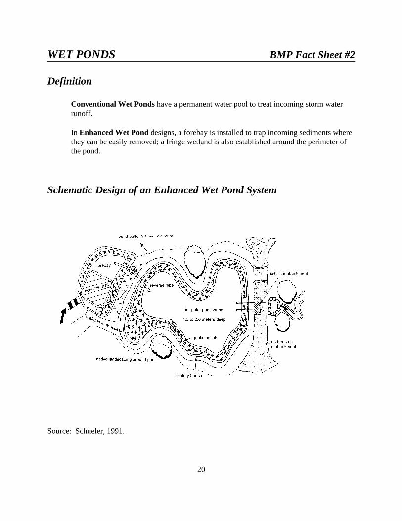
Conventional Wet Ponds have a permanent water pool to treat incoming storm waterrunoff.
In Enhanced Wet Pond designs, a forebay is installed to trap incoming sediments wherethey can be easily removed; a fringe wetland is also established around the perimeter ofthe pond.
Schematic Design of an Enhanced Wet Pond System
Source: Schueler, 1991.

21
Pollutant Removal Capability:
Conventional wet ponds provide moderate to high removal of both particulate and solubleurban storm water pollutants. Reliable removal rates can be achieved with pool sizesranging from 0.5 to 1.0 inches of runoff per impervious acre.
Pollutant Removal Mechanisms: Achieved by gravitational settling, algal settling,wetland plant uptake and bacterial decomposition (Driscoll, 1983). The degree ofpollutant removal is a function of pool size in relation to contributing watershed area.
Review of Monitoring Studies: The pollutant removal capability of conventional wetponds is well documented with over twenty performance monitoring studies inpublication. Reported sediment removal typically ranges from 50-90%. Totalphosphorus removal ranges from 30-90 %. Removal of soluble nutrients ranges from 40-80%. Moderate to high removals of trace metals, coliforms and organic matter arefrequently reported.
Factors Influencing Pollutant Removal:
Positive Factors• Pretreatment by sediment
forebay (Livingston, 1989)• Permanent pool, 0.5 - 1.0 inches per
impervious acre treated (6,15)• Fringe wetlands• Shallow wetlands and/or extended
detention may improve removalefficiencies (Adams, et. al., 1983)
• High length to width ratios
Negative Factors
• Small pool size (Driscoll, 1983)• Fecal contribution from large
waterfowl populations (Wu, et. al.,1988)
• Short-circuiting and turbulence(Martin, 1988)
• Sediment phosphorus release• Extremely deep pool depths (greater
than 10 feet)• Snowmelt conditions and/or ice
(Oberts, et. al., 1989)
Feasibility:
Feasibility: Wet ponds can be utilized in both low and high visibility developmentsituations if contributing watershed area is greater than ten acres and/or a reliable sourceof baseflow exists.
Adaptability: Wet pond designs are not generally useful in arid regions whereevapotranspiration significantly exceeds precipitation on an annual basis. Also, the sizeof the pool will need to reflect the prevailing climate and runoff frequency for a particular

22
region. Ponds can be used in colder northern climates, but their performance declinesslightly during ice and snowmelt runoff conditions. This practice may not be effective inmore arid areas. Applications in Wyoming will need to be carefully chosen.
Contributing Watershed Area: Contributing watershed areas greater than ten acres andless than one square mile are generally suitable for wet ponds.
Baseflow: Dry-weather baseflow is needed to maintain pool elevations and prevent poolstagnation.
Available Space: Wet ponds and associated buffer/setbacks can consume from one tothree percent of total site area.
Development Situations: Very useful in both low and high visibility commercial andresidential development applications.
Use in Ultra-urban Areas: Use in ultra-urban areas is fairly limited due to spaceconstraints, but can provide an attractive urban amenity if open space or parkland isavailable.
Retrofit Capability: Occasionally used for storm water retrofits, particularly within drystorm water basins (Schueler, et. al., 1991). Often used in combination with wetlands orextended detention treatment techniques.
Storm Water Management Capability: Most wet ponds can provide two-year stormwater quantity control, in addition to quality control.
Maintenance:
Wet ponds have a modest maintenance burden, consisting primarily of inspections,mowing of the embankment and buffers, and removal of sediment, trash and debris fromthe forebay. All studies to date indicate that pond sediments meet sludge toxicity limitsand can be safely land filled (23,53,54)
Factors Influencing Longevity: Well-designed wet ponds can function for twenty yearsor more and very few conventional ponds have ever failed to provide some water qualitybenefit. Performance will decline over time, however, unless regular sediment clean outis undertaken. Factors influencing the longevity of wet ponds include:
• Installation of a sediment forebay (Schueler, 1992)• Regular (2 - 5 year) sediment clean-outs (Schueler and Helfrich, 1988)• Reverse-slope pipes • On-site sediment disposal area

23
• Use of concrete riser/barrels rather than corrugated metal pipe
Potential Benefits/Concerns:
Positive Impacts:• Creation of wetland features
• Creation of aquatic and terrestrial habitat (particularly for waterfowl)
• Creation of a warm-water fishery
• High community acceptance and landscaping values (Adams, et. al., 1983)
• Pollutant removal and downstream channel protection
Negative Impacts:• Downstream warming (Galli, 1991). May not be appropriate on streams with cold
water fisheries.
• Upstream channels may be impacted when wet ponds serve large drainage areas(> 250 acres) (Schueler, 1991)
• Potential loss of wetlands, forest and floodplain habitat associated with poor siteselection for the pool (Schueler, 1991)
• Downstream shifts in trophic status (Galli, 1988)
• Limited risk of ground water quality impacts over the long term; all studies to dateindicate that wet ponds do not significantly contribute to ground watercontamination (USEPA, 1991)
• Potential hazard for nearby residents due to the presence of standing water. Theinclusion of a shallow safety bench around the pond may reduce potential hazards. Additionally, growth of dense vegetation (cattails, willows, etc.) will limit accessand hazards to residents.
• Provide areas for insect nuisances such as mosquitos that will need control

24
STORM WATER WETLANDS BMP Fact Sheet #3
Definition
Conventional Storm Water Wetlands are shallow pools that create growing conditionssuitable for the growth of marsh plants. These storm water wetlands are designed tomaximize pollutant removal through wetland uptake, retention and settling. Storm waterwetlands are constructed systems and typically are not located within delineated naturalwetlands. In addition, storm water wetlands differ from other artificial wetlands createdto comply with mitigation requirements in that they do not replicate all the ecologicalfunctions of natural wetlands. Functional differences will depend on the design of thestorm water wetland, interactions with groundwater and surface water, and local stormclimate.
Enhanced Storm Water Wetlands are designed for more effective pollutant removaland species diversity. They also include design elements such as a forebay, complexmicrotopography, and pondscaping with multiple species of wetland trees, shrubs andplants.
Schematic Design of an Enhanced Shallow Marsh System

25
Pollutant Removal Capability:
In general, conventional storm water wetlands have a high pollutant removal capabilitythat is generally comparable to that of conventional wet ponds. Sediment removal maybe greater in well designed storm water wetlands, but phosphorus removal is morevariable.
Pollutant Removal Mechanisms: Wetlands remove pollutants through gravitationalsettling, wetland plant uptake, adsorption, physical filtration and microbialdecomposition. Primary removal of storm water pollutants occurs during the relativelylong quiescent period between storms (Livingston, et. al., 1997). The degree of pollutantremoval is a function of aquatic treatment volume, surface area to volume ratio, and theratio of wetland surface area to watershed area (16, 26, 27). Additionally, longer stormwater flow paths through the wetland and longer residence times within the wetland isexpected to improve pollutant removal.
In western states wetland vegetation may be dormant during early spring snowmelt andrain events. However, since plant uptake is only one of several mechanisms in theremoval of most pollutants, a standing crop of vegetation can still provide filtration andan area for surface removal processes (Livingston, et. al., 1997).
Review of Monitoring Studies: Eighteen studies of the performance of conventionalnatural and constructed wetlands are available. Removal rates are generally comparableto those reported for conventional wet ponds of similar treatment volume; however,sediment removal rates are often slightly higher and nutrient removal rates are somewhatlower. Some cases of negative removal for ammonia and ortho-phosphorus werereported. The addition of ammonia or ortho-phosphorous may be due, in part, to wildlifeuse and populations and vegetation management (Livingston, et. al., 1997). Overallperformance is greatest during the growing season and lowest during the winter months(Strecker, et. al., 1990).
Factors Influencing Pollutant Removal:
Positive Factors
• Constant pool elevations (Schueler, 1992)• Range of micro topography within the
wetland (Schueler, 1992)• Sediment forebay• High surface area to volume ratio
(Strecker, et. al., 1990)• Constructed wetland performs better than
natural wetland
• Adding greater retention volumeand/or detention time to thewetland (26, 28)
• Effective in areas with high watertable or poorly drained soils(Livingston, et. al., 1997)
• Lengthy travel paths for stormwater
26
Negative Factors
• Lower removal rate during non-growingseason (Athanas and Stevenson, 1991)
• Concentrated inflows (Strecker, et. al.,1990)
• Wetland area less than two percent ofwatershed area
• Sparse wetland cover (OWML andGMU, 1990)
• Ice cover or snowmelt runoff(Oberts, et. al., 1989)
Feasibility:
Feasibility: Enhanced storm water wetlands can be applied to most developmentsituations where sufficient baseflow is available to maintain water elevations.
Adaptability: Enhanced storm water wetlands can be adapted for most regions of thecountry that are not excessively arid. Storm water wetlands may not be appropriate for allareas of Wyoming. A careful review of local climate and water table conditions shouldbe conducted before choosing this BMP.
Contributing Watershed Area: Storm water wetlands can be used in watersheds assmall as five acres. However, the installation of many small wetlands increasemaintenance costs (Galli, 1992). “Pocket wetlands” (generally less than 0.1 acres) havebeen used successfully at culvert and parking lot outlets in Minnesota (Debo and Reese,1995).
Presence of Baseflow: To maintain a constant water level, it is often necessary to have areliable dry-weather baseflow to the wetland or a groundwater supply.
Permeable Soils: It is difficult to establish wetlands at sites with sandy soils, high soilinfiltration rates or high summer evapotranspiration rates.
Available Space: Because of their shallow depths, storm water wetlands can consumetwo to three times the site area compared to other storm water quality options (in somecases, as much as five percent of total site area). The land requirements of storm waterwetlands can be sharply reduced by deepening parts of the wetland, thus extendingdetention times. However, side slopes along the edge of the wetland must remain gradualto maintain emergent vegetation around the wetland.
Use in Ultra-urban Areas: Limited due to space constraints; however, pollutantremoval can be obtained by modifying existing degraded urban wetlands for storm watercontrol. Incorporating a shallow “safety bench” around the edge of a wetland or

27
promoting dense vegetative growth around the perimeter to limit access, may mitigatesome safety concerns in urban areas.
Retrofit Capability: The addition of wetland features to older dry storm water basins isan effective retrofit technique (Strecker, et. al., 1990). Many retrofits utilize acombination of extended detention, wetlands and a permanent pool.
Storm water Management Capability: In most cases, storm water detention can beprovided in storm water wetlands.
Maintenance:
Well designed conventional storm water wetlands should function for many years. Theinclusion of a forebay, or wet cell, that concentrates sediment deposition in an area whereit can be easily removed without disturbing the entire system is an important part of thedesign.
Storm water wetlands may require greater maintenance in the first several years toestablish the marsh. Thereafter, the maintenance burden is similar to other pond systems.
Factors Influencing Longevity:
• Sediment forebay to collect sediment before it enters the wetland• Ability to regulate water depths• Replacement plantings (Schueler, 1992)• Selection of an experienced wetland contractor for design (RIDEM, 1989)• Control of undesirable plant species such as purple loosestrife
Failure Rates: While most conventional storm water wetlands have persisted over time,the quality and coverage of wetland plants may not be optimal for pollutant removal. Itshould be noted that few storm water wetlands meet the strict success criteria for wetlandmitigation, but they are not intended to do so.
Potential Benefits/Concerns:
Positive Impacts:
Storm water wetlands can provide an excellent urban habitat for wildlife andwaterfowl, particularly if they are surrounded by a buffer and have some deeperwater area (Athanas, 1986)
28
Negative Impacts:
Possible impact on wetland biota from trace metal uptake (Strecker, et. al., 1990)
Storm water wetlands may cause warming of downstream waters (Galli, 1991)
Construction may adversely impact existing wetland or forest areas (6, 30)
Possible takeover by invasive aquatic nuisance plants (e.g., loosestrife, cattailsand phragmites) (Stockdale, 1991)
Bacterial contamination if waterfowl populations are dense (Wu, et. al., 1988)
If sediment is not properly settled out before the storm water enters the wetland,the wetland will likely become choked with sediment in a few years
Provide areas for insect nuisances such as mosquitos that will need control
29
MULTIPLE POND SYSTEMS BMP Fact Sheet #4
Definition
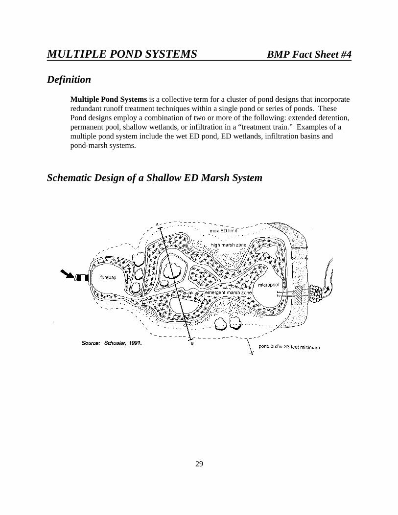
Multiple Pond Systems is a collective term for a cluster of pond designs that incorporateredundant runoff treatment techniques within a single pond or series of ponds. ThesePond designs employ a combination of two or more of the following: extended detention,permanent pool, shallow wetlands, or infiltration in a “treatment train.” Examples of amultiple pond system include the wet ED pond, ED wetlands, infiltration basins andpond-marsh systems.
Schematic Design of a Shallow ED Marsh System

30
Cross-section View of a Standard ED Pond System Design
Schematic Design of a Dry In-filter System
31
Multiple pond systems (MPS) have evolved as a common approach to provide storm waterquality control over the past five years. MPS is a collective term for a wide variety of approachesto storm water pond design. While many aspects of their design are unique and site-specific,they do share several common features:
Redundancy: The MPS designs emphasize the use of multiple treatment mechanisms(such as a permanent pool, extended detention, wetlands, within a pond or series ofponds), rather than a single method of treatment. The use of treatment methods in serieshelps to improve both the level and reliability of pollutant removal provided by the pondsystem.
Flexibility: Because the location and allocation of treatment mechanisms is not rigid, thedesigner of an MPS has a great deal of flexibility in responding to site-specificconditions. Additionally, the flexibility enables the designer to minimize or avoidnegative environmental impacts that can be created by single ponds.
Complexity: MPS are inherently more complex in design than single treatment ponds. Typically, MPS systems have more sophisticated hydrologic control devices that aretargeted toward different patterns of the annual runoff frequency spectrum. In addition,some MPS have interconnected cells within a pond.
Pollutant Removal Capacity:
Many MPS are reported to provide incrementally higher and more consistent levels of urbanpollutant removal in comparison to single treatment systems. This improvement is due to anumber of factors:
Multiple-cell Ponds: Studies have shown that multiple cell ponds tend to haveincrementally higher levels of pollutant removal when compared to single cell ponds(Horner, 1988). The superior performance of multiple cell ponds can be attributed to alonger flow path, possible reductions in short circuiting, and increases in retention time. Short circuiting occurs when inflow by passes “dead storage” areas where little or nomixing occurs. Multiple pond systems lengthen the path of storm water flow with respectto the width of the pond areas, reducing or avoiding short circuiting.
Wet Pond/Wetland Systems: MPS that utilize a wet pond cell leading to a wetland cellhave been reported to be very effective in removing pollutants from urban runoff (19,28,33, 34). The wet pond cell is apparently very effective in pre-treating the incomingrunoff; it also reduces its velocity and distributes it more evenly across the marsh.
Extended Detention/Wetland Systems: Wetlands are believed to improve theeffectiveness of conventional extended detention (ED) in several ways. The plants helpstabilize deposited sediments, take up nutrients, and create more ideal settling conditions.

32
The extent of the improved pollutant removal attributable to ED-wetland systems is notwell documented, however. Four performance studies of ED-wetland systems have beenreported and these indicate moderate to high removal of particulate pollutants, and low tomoderate removal of soluble pollutants. However, all four systems studied hadinadequate treatment volumes to provide for optimum pollutant removal (0.08 to 0.15inches of runoff per contributing acre).
Wet Extended Detention Ponds: The wet extended detention pond system has beenprojected to have higher and more reliable pollutant removal than a wet pond or an EDpond acting alone. This superior performance is due to the role of the pool in acting as abarrier to re-suspension and the role of ED in increasing retention times for the full rangeof storms (Schueler and Helfrich, 1988). Limited monitoring conducted to date supportsthis contention.
Feasibility:
MPS are generally subject to the same feasibility requirements associated withconventional pond systems.
Adaptability: MPS are adaptable for use in most regions of the country. In arid orextremely cold regions, more of the total storage in the MPS should be devoted toextended detention. In cold regions extended detention provides more volume forsnowmelt and early spring rains. In arid areas maintaining large wetlands without aconsistent water source may not be practical.
Maintenance:
MPS have a maintenance burden similar to that of conventional pond systems. While the MPSmay have more complex operation (e.g., adjustment of valves), their design incorporatesnumerous features that can reduce routine and non-routine maintenance (e.g., mowing andsediment removal).
Longevity: The longevity of MPS is expected to be at least comparable to conventionalpond systems. Often, one treatment storage component can be used to protect the longterm capacity of another component. For example:
Wet Pond/Wetland Systems: The wet pond cell traps the majority of the incomingsediment, thereby preserving treatment capacity in the wetland and maintaining optimumwater depths.
Dry Infilter Systems: The plunge pool, grassed swale and filter fabric provide excellentpretreatment of runoff before it enters the trench, thereby enhancing its longevity. A dryinfilter pond has been operating with only minor clogging for over six years in Maryland.

33
All Multiple Pond Systems: The basic design of all MPS has two features that promotegreater longevity for ponds. The first is the subsurface reverse-slope pipe used as thehydrological control device. This design feature greatly reduces clogging. The seconddesign feature is the forebay, or wet cell, which concentrates sediment deposition in anarea where it can be easily removed without disturbing the entire system.
Environmental Attributes:
The flexibility of MPS enables the designer to minimize or avoid many secondary impactscommonly associated with ponds. The ability to allocate treatment storage components, or locatethem in series can aid the designer in customizing the MPS to avoid disruption to forests andwetlands. Similarly, by allocating less storage to the permanent pool (and more to ED), one canreduce the potential delta of the pond. In addition, by combining wetlands with conventional wetponds or extended detention ponds, it is possible to significantly enhance the habitat value. Finally, by adding ED to wetlands or wet ponds, one can provide a greater degree of downstreamchannel protection. A comparison of some of the advantages and disadvantages of alternativepond designs are illustrated in Appendix A, Table 1.

34
INFILTRATION TRENCHES BMP Fact Sheet #5
Definition
a Conventional Infiltration Trench is a shallow, excavated trench that has beenbackfilled with stone to create an underground reservoir. Storm water runoff divertedinto the trench gradually exfiltrates from the bottom of the trench into the subsoil andeventually into the water table. Trenches may be designed to accept the “first flush”volume (½ runoff per acre of impervious surface) or for larger volumes of runoff. Adesign variation is a dry well to control small volumes of runoff, such as roof top runoff.
Enhanced Infiltration Trenches have extensive pretreatment systems to removesediment and oil.
Both types of trenches require on-site geotechnical investigations to determineappropriate design and location.
Schematic Design of a Conventional Infiltration Trench

35
Pollutant Removal Capability:
Although actual performance data on conventional infiltration trenches is rare, trenches arebelieved to have high capability to remove particulate pollutants and a moderate capability toremove soluble pollutants.
Pollutant Removal Mechanisms: Include adsorption, straining and microbialdecomposition in the soil below the trench and trapping of particulate matter withinpretreatment areas (i.e., grass filter strips, sump pits and plunge pools) (Schueler, 1987).
Review of Monitoring Studies: Very few studies monitoring the performance ofconventional infiltration trenches have been conducted to date (Woodward-Clyde, 1991). Estimates of performance have been inferred from studies of rapid infiltration landwastewater treatment systems or by modeling (1, 21). For sediment removal, rates inexcess of 90% are cited; for phosphorus and nitrogen removal, the rate is estimated at60%. Removal rates for trace metals, coliforms and organic matter are estimated at 90%. Lower rates are expected for nitrate, chlorides and soluble trace metals, particularly insandy soils (25, 35).
Factors Influencing Pollutant Removal:
Positive Factors• Bank run or washed aggregate• High organic matter and loam content of
subsoil (Kuo, et. al., 1990)• Capture of a large fraction of annual
runoff volume• Effective pretreatment system, e.g., a
sump pit (Schueler, et. al., 1991)• Pretreatment of sediments, oils, greases
Negative Factors• Sandy soils • Trench clogging• High water table• Long de-watering times (Galli,
1992)
Feasibility:
Feasibility: The application of trenches, like other infiltration practices, is severelyrestricted by soils, water table, slope and contributing area conditions. These conditionsmust be carefully investigated in the field before proceeding with design.
Adaptability: The widespread use of infiltration trenches may be limited in areas wherethe ground commonly freezes or more arid climates where wind erosion may introduce asignificant sediment load. Infiltration trenches are also less effective in regions wheresoils are predominantly clays or silts.

36
Soils: Trenches are not practical in soils with field-verified infiltration rates of less than0.5 inches per hour (particularly silty or clayey soils). Soil borings should be taken wellbelow the proposed bottom of the trench to identify any restricting layers (MDE, 1983).
Area: Maximum contributing drainage area to an individual trench should not exceedfive acres.
Slope: The effectiveness of surface trenches is sharply reduced if slopes are greater thanfive percent.
Depth to Bedrock and Depth to Water Table: Three feet of clearance from bottom oftrench to the water table is recommended.
Ground Water: Trenches may not be easily adaptable in regions where ground water isused locally for human consumption or in areas where particularly hazardous pollutantsmay be present.
Sediment Inputs: Conventional trenches may not be advisable on sites expected toprovide high levels of sediment input.
Climate: Trenches may not perform well in regions with long, cold winters and deepfreeze-thaw levels. Trenches may not be appropriate in arid regions with sparsevegetative cover in upland areas that might contribute high sediment levels.
Use in Ultra-urban Areas: Very limited due to unsuitable soils. Soils in urban areas areoften disturbed and compacted due to previous construction or landscaping.
Retrofit Capability: Very limited due to unsuitable soils (Galli and Herson, 1989).
Storm water Management Capability: Some trench designs can provide storm waterquantity requirements; however, most trenches function only as water quality BMPS.
Maintenance:
To enhance longevity and maintain performance, trenches and associated pretreatmentsystems do require significant maintenance. Most conventional trenches do not appear tobe regularly maintained in the field and thus many will require costly rehabilitation orreplacement to maintain their function.
Longevity: Thus far, conventional trenches have proved to have short life spans. Slightly over half partially or totally fail within five years of construction. Longevitycould be greatly improved through the utilization of enhanced trenches (i.e., runoffpretreatment, better geotechnical evaluation and regular maintenance).

37
An underdrain installed during construction of an infiltration trench may increaselongevity by allowing conversion to a sand filter should the trench fail due to poorexfiltration. The drain would remain capped until the trench failed.
Factors Influencing Longevity: The relatively short life span of conventional trenchescould be significantly increased by the following:
• Field verification of soil infiltration rates and water table location (Galli, 1992)
• Careful site selection to avoid areas with very high sediment loads.
• Use of pretreatment systems that provide some degree of storage (e.g. sump pits,swales with check dams, plunge pools) (Galli, 1992)
• A layer of filter fabric one foot below surface of trench (Schueler, 1987)
• Use of a sand layer rather than filter fabric at the bottom of a trench (Galli, 1992)
• Avoiding construction until all contributing watershed disturbances andconstruction activities are completed (MDE, 1983)
• Rototilling of trench bottom to preserve infiltration rates (Galli, 1992)
Failure Rates: According to data from Maryland (Metropolitan Washington Council ofGovernments), about one in five conventional trenches fails to operate as designedimmediately after construction; further-more, barely half of all conventional infiltrationtrenches operated as designed after five years. (Many of these had become partially ortotally clogged.) Based on these data, it would appear that conventional trenches have adesign life-span of less than five years without adequate pretreatment.
A second study of infiltration trench longevity in Maryland indicated that approximatelyfifty-five percent of trenches are not operating as designed (Galli, 1992). According tothe study, one-third of the trenches were partially or totally clogged; another twentypercent had significant inflow problems. The oldest trench surveyed was five years old.
Potential Benefits/Concerns:
Positive Impacts:
• Groundwater recharge
• Reduction in downstream bank full flooding events
• Some reduction of peak storm water discharge

38
Negative Impacts:
• Slight to moderate risk of groundwater contamination depending on soilconditions. Infiltration trenches or basins are not recommended in areas where thepotential of significantly polluted surface runoff exists.
• No habitat is created
• High failure rates of conventional trenches sharply limit the ability to meet stormwater and water quality goals at the watershed scale
• May cause an increase in the groundwater table, resulting in flooding of structureswith basements. This is more likely to be a problem in areas with existing highwater table.

39
INFILTRATION BASINS BMP Fact Sheet #6
Definition
Infiltration basins are impoundments where incoming storm water runoff is stored untilit gradually exfiltrates through the soil of the basin floor.
Schematic Design of an Infiltration Basin
Pollutant Removal Capability:
No performance data on infiltration basins is available; however, they are presumed to have thesame general removal efficiencies reported for infiltration trenches: high removal for particulatepollutants and moderate removal for soluble pollutants.

40
Pollutant Removal Mechanisms: As with other infiltration systems, removal isaccomplished by adsorption, straining, and microbial decomposition in the basin subsoilsas well as the trapping of particulate matter within pretreatment areas (Schueler, 1987). Drainage of the basin should occur within a minimum of 72 hours to maintain aerobicconditions and promote microbial removal of pollutants.
Review of Monitoring Studies: No actual performance data is available to evaluate thepollutant removal capability of infiltration basins (Woodward-Clyde, 1991). Estimateshave been inferred from studies of rapid infiltration of land-applied wastewater effluentand from modeling studies (Schueler, 1987). Removal efficiencies are presumed to behigh for particulate pollutants and moderate for soluble pollutants. Lower rates areexpected for nitrate, chlorides and soluble trace metals, particularly in sandy soils(USEPA, 1991). Actual pollutant removal is projected to be related to the proportion ofthe annual runoff volume successfully exfiltrated into the subsoil.
Factors Influencing Pollutant Removal:
Positive Factors• Forebay• Short dewatering time• Back-up underdrain systems• Small contributing watershed• Dense vegetative cover• Non-concentrated flow• Drainage within 24-72 hours
Negative Factors• Basin clogging• High water tables• Clay and silt soils• High sediment inputs• Large contributing watershed area• Long dewatering times• Algal growth• Large depth of standing water (Galli,
1992)
Feasibility:
Feasibility: The application of basins is restricted by numerous site factors (soils, slope,water table and contributing watershed area).
Adaptability: Infiltration basins may not be applicable in areas of cold winters, aridgrowing seasons or impermeable soils.
Soils: Basins are not feasible at sites with field-verified soil infiltration rates of less than0.5 inches/hour. Soil borings should be taken well below the proposed bottom of thebasin to identify any restricting layers (MDE, 1983).
Contributing Watershed Area: Normal contributing drainage area ranges from two tofifteen acres. Larger drainage areas are not generally recommended.

41
Depth to Bedrock/Seasonally High Water Table: Minimum of three feet.
Sole-Source Aquifers: Regions with sole-source aquifers may not be suitable.
Pretreatment: Basins are not recommended unless upland sediment inputs can bepretreated.
Land Use: Some caution should be exercised when applying a basin in a watershed witha risk of chronic oil spills or other hazardous materials.
Use in Ultra-urban areas: Not recommended.
Retrofit Capability: Not recommended (Schueler, et. al., 1991).
Storm water Management Capability: In some instances, a basin can provide stormwater management detention, but it is not generally recommended.
Maintenance:
Regular maintenance activities apparently cannot prevent rapid clogging of infiltrationbasins. Once clogged, it has been very difficult to restore their original function; thus,many have been converted to retention basins or wetlands.
Longevity: Infiltration basins do not have long life spans. Sixty to one hundred percentof basins studied could no longer exfiltrate runoff after five years. Major designrefinement and site investigation will be required to achieve sufficient longevity.
Installation of a back-up underdrain may extend the life of a basin by essentiallyconverting it into a sand filter. The drain, normally capped, may be opened whenexfiltration is no longer effective.
Failure Rates: The failure rates for infiltration basins in the mid-Atlantic region rangefrom sixty to one hundred percent in the first five years, according to two recent studies(8, 36, 37). Up to fifty percent had failed shortly after construction. The primary reasonfor failure is clogging. Of twelve basins in Maryland, none were able to exfiltrate runoffafter five years (Galli, 1992). These basins had an average standing water depth of onefoot.
All these basins were partially covered by wetland vegetation and/or algal mats. Thebasins had become defacto retention ponds; some sixty percent were still providingpartial water quality treatment. About twenty percent of infiltration basins studied inMaryland have been retrofitted into pond systems (MDE, 1991).

42
Factors Influencing Longevity: Clearly, current infiltration basin designs do notperform adequately. The following factors appear to contribute significantly to improvedlife-span for infiltration basins:
• Shorter dewatering rate (24 hours rather than 72 hours)
• Pretreatment forebays to control sediment inputs
• Small contributing watershed areas
• Shallow basin depths (standing water appears to promote soil compaction)
• Off-line designs that bypass large storms and sediment inputs
• More efficient dewatering mechanisms in basins (e.g., stone trenches rather thansoil) (Bergling, 1991)
• Careful geotechnical investigation of soil conditions prior to excavation
• Use of sand as a surface layer in the basin
• Installation of underdrains into the basin
It is difficult to determine whether the design changes, as proposed above, would achievesufficient longevity. Local communities should be cautious in promoting infiltration basins until:
• the longevity and performance of the new generation of infiltration basins isadequately demonstrated
• the basic infiltration basin design is readily convertible into a retention basin
Potential Benefits/Concerns:
Positive Impacts:
• Groundwater recharge helps to maintain dry-weather flows in streams
• Reduction in downstream bank full flooding events. Partial replication of pre-development hydrology.
(Note: The short lifetimes of basins as currently designed suggest that the positivehydrological and water quality impacts may not be realized in practice.)
43
Negative Impacts:
• Slight to moderate risk of local groundwater contamination (particularly ifcontributing watershed is industrial or has heavy vehicular petroleum wash off).
• Infiltration basins provide some habitat value, but this is quite modest incomparison to that provided by pond systems. Failed basins provide better habitatthan functioning basins.
• Infiltration basins in close proximity to streams or lakes may degrade waterquality if there is a rapid hydraulic connection between the basin and nearbysurface water
• May cause an increase in the local ground water table resulting in flooding ofnearby basements. This is most likely to be a problem in areas of high existingground water table.

44
POROUS PAVEMENT BMP Fact Sheet #7
Definition
Porous Pavement is an alternative to conventional pavement whereby runoff is divertedthrough a porous asphalt layer and into an underground stone reservoir. The stored runoffthen gradually infiltrates into the subsoil.
Schematic Design of a Porous Pavement System

45
Pollutant Removal Capability:Operating porous pavement systems have been shown to have high removal rates forsediment, nutrients, organic matter, and trace metals. The majority of the removal occursas the result of the exfiltration of runoff into the subsoil, and subsequent adsorption orstraining of pollutants within the subsoil.
Pollutant Removal Mechanisms: Include adsorption, straining, and microbialdecomposition in the subsoil below the aggregate chamber, and trapping of particulatematter within the aggregate chamber. In addition, up to 90% of the annual rain fallvolume is diverted to groundwater rather than surface runoff (Schueler, 1987).
Review of Monitoring Studies: Two monitoring studies have been conducted thatindicate high long-term removal of sediment (up to 80%), phosphorous (up to 60%), andnitrogen (up to 80%), as well as high removal rates for trace metals and organic matter(39, 41). The majority of pollutant removal at porous pavement sites is due to thereduction of mass loadings via the groundwater. Measured concentrations of sediment,phosphorous, and nitrogen are only slightly reduced in the small, measured outflows fromporous pavement.
Factors Influencing Pollutant Removal:
Positive Factors• High exfiltration volumes• Routine vacuum sweeping• Maximum drainage time of two days• Highly permeable soils• Clean-washed aggregate• Organic matter in subsoils• Pretreatment of off-site runoff
Negative Factors• Poor construction practices• Inadequate surface maintenance• Use of sand during snow conditions• Low exfiltration volumes
Feasibility:
Feasibility: The use of porous pavement is highly constrained, requiring deep andpermeable soils, restricted traffic, and suitable adjacent land uses.
Adaptability: Use of porous pavement may be restricted in regions with colder climates,arid regions or regions with high wind erosion rates, and in areas of sole-source aquifers.
Soils: Porous pavement is not practical in soils with field verified infiltration of less than0.5 inches per hour. Soil borings must be taken two to four feet below the aggregate toidentify any restricting layers.

46
Area: Most porous pavement sites are less than ten acres in size. This primarily reflectsthe perceived economic and liability problems associated with larger applications.
Slope: Less than five percent.
Depth to Bedrock and Water Table: Three feet minimum clearance from bottom ofsystem.
Sole-Source Aquifer: Use of porous pavement should be evaluated carefully in regionswhere water is supplied by a single aquifer.
Traffic Volumes: Porous pavement is not recommended for most roadways and cannotwithstand the passage of heavy trucks. Typically, porous pavement is recommended forlightly used satellite parking areas and access roads.
Sediment Inputs: Porous pavement is not advisable in areas expected to provide highlevels of off site sediment input (e.g., upland construction, sparsely vegetated uplandareas and areas with high wind erosion rates)
Cold Climates: While the standard porous pavement design is believed to withstandfreeze/thaw conditions normally encountered in most regions of the country, the porouspavement system is very sensitive to clogging during snow removal operation (e.g.,application of sand and de-icing chemicals and scraping by snow plows).
Use in Ultra-urban Areas: Some possibilities exist for the use of porous pavementduring in-fill development provided that suitable soils are present,
Retrofit Capability: Extremely limited. Most soils in urbanized watersheds have beenpreviously modified and so are not capable of providing adequate infiltration rates.
Storm Water Management Capability: Porous pavement sites can meet storm watermanagement requirements in many cases.
Maintenance:Quarterly vacuum sweeping and/or jet hosing is needed to maintain porosity. Field datahowever indicate that this routine maintenance practice is not frequently followed.
Longevity: Porous pavement sites have a high failure rate (75 %). Failure is due topartial or total clogging of the area that occurs:• Immediately after construction• Over time, when porous asphalt is clogged by sediment and oil• When pavement is resurfaced with non-porous materials
47
Factors Influencing Longevity:
• Routine vacuum sweeping• Use in low intensity parking areas• Restrictions on access by heavy trucks, use of de-icing chemicals and sand• Resurfacing• Inspection and enforcement of specifications during construction• Pretreatment of off-site runoff• Extra-ordinary sediment control during construction
Failure Rates: Seventy-five percent of all porous pavement systems surveyed inMaryland have partially or totally clogged within five years. Failure has been attributedto inadequate construction techniques, low permeable soils and/or restricting layers,heavy vehicular traffic, and resurfacing with nonporous pavement materials. Somefraction of the clogged porous pavement sites could be rehabilitated with drop inlets andproviding outlets from the aggregate chamber. The oldest operating porous pavementsystems are about ten years old.
Potential Benefits/Concerns:
Positive Impacts:
• Porous pavement can divert large volumes of potential surface runoff togroundwater recharge and, in some cases, provide even greater recharge than pre-development conditions (OWML, 1986)
• Porous pavement can reduce downstream bank-full flooding
• Provides storm water quantity and quality treatment on-site, thereby protectingwoodland, wetland, and stream valleys elsewhere on the site (Cahill, et. al., 1991)
Negative Impacts:
• Slight to moderate risk of groundwater contamination depending on soilconditions and aquifer susceptibility
• Possible transport of hydrocarbons from vehicles and leaching of toxic chemicalsfrom asphalt/or binder surface
• The high failure rate of porous pavement sharply limits the ability to meetwatershed storm water quality and quantity goals
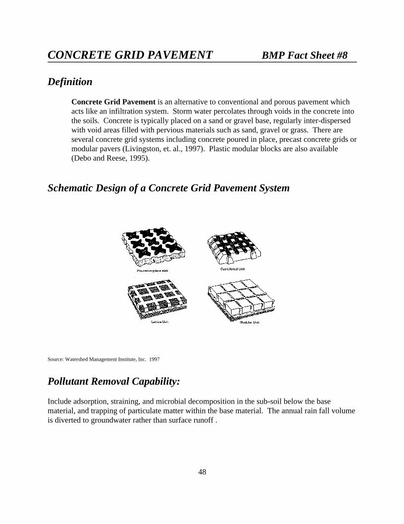
48
CONCRETE GRID PAVEMENT BMP Fact Sheet #8
Definition
Concrete Grid Pavement is an alternative to conventional and porous pavement whichacts like an infiltration system. Storm water percolates through voids in the concrete intothe soils. Concrete is typically placed on a sand or gravel base, regularly inter-dispersedwith void areas filled with pervious materials such as sand, gravel or grass. There areseveral concrete grid systems including concrete poured in place, precast concrete grids ormodular pavers (Livingston, et. al., 1997). Plastic modular blocks are also available(Debo and Reese, 1995).
Schematic Design of a Concrete Grid Pavement System
Source: Watershed Management Institute, Inc. 1997
Pollutant Removal Capability:
Include adsorption, straining, and microbial decomposition in the sub-soil below the basematerial, and trapping of particulate matter within the base material. The annual rain fall volumeis diverted to groundwater rather than surface runoff .

49
Pollutant Removal Mechanisms: Reduce surface water pollutant and sediment loading inrunoff from parking lots or other surfaces through infiltration of storm water and runoffreduction.
Factors Influencing Pollutant Removal:
Positive Factors• Peak flow control• Groundwater recharge• No additional land consumption
Negative Factors• Requires regular maintenance• Improper soils or slope• Traffic restrictions• Spills of hazardous materials may
contaminate soils or ground water• May be hazardous to wearers of high-
heeled shoes
Feasibility:
Feasibility: Useful where permeable soils, low slopes and low traffic conditions arepresent.
Adaptability: Not suited to impermeable or shallow soils. High wind erosion areas andcold climates may also render the application unsuitable.
Soils: Concrete grid pavement is not practical in impermeable or shallow soils.
Area: Most concrete grid pavement sites are small in size.
Slope: Low.
Traffic Volumes: Concrete grid pavement is not recommended for most roadways andcannot withstand the passage of heavy trucks. Typically, concrete grid pavement isrecommended for lightly used satellite parking areas and access roads.
Sediment Inputs: Concrete grid pavement is not advisable in areas expected to providehigh levels of off site sediment input (e.g., upland construction, sparsely vegetated uplandareas and areas with high wind erosion rates)
Cold Climates: May not perform well in extreme freeze/thaw conditions.
Retrofit Capability: Extremely limited. Most soils in urbanized watersheds have beenpreviously modified and so are not capable of providing adequate infiltration rates.

50
Storm Water Management Capability: Concrete grid pavement sites can meet stormwater management requirements in many cases.
Maintenance:
Concrete grid pavement has moderate to high maintenance needs. Paving blocks have anadvantage over porous pavement in that they tend to seal less easily and replacing individualblocks is easier than patching porous pavement. However, they tend to be less able to withstandloads without misalignment.
“Good housekeeping” to minimize the introduction of particulates to the pavement.
Replacement of base and underlying soils if clogging occurs.
Fertilizers and pesticides should be used sparingly if turf is incorporated into thepavement since they may adversely affect ground water and concrete products.
Potential Benefits/Concerns:
Positive Impacts:
• Concrete grid pavement can divert large volumes of potential surface runoff togroundwater recharge and, in some cases, provide even greater recharge than pre-development conditions
• Concrete grid pavement can reduce downstream bank-full flooding
Provides water runoff control without consumption of land.
Negative Impacts:
• Slight to moderate risk of groundwater contamination depending on soilconditions and aquifer susceptibility
• Possible transport of hydrocarbons from vehicles

51
SAND FILTERS BMP Fact Sheet #9
Definition
Sand filters are a relatively new technique for treating storm water, whereby the firstflush of runoff is diverted into a self-contained bed of sand. The runoff is then strainedthrough the sand, collected in underground pipes and returned back to the stream orchannel. Storage is generally calculated on the runoff volume of 0.5 inches of rainfall perimpervious acre (Debo and Reese, 1995).
Sand filters may be an “unconfined,” sand-filled trench with a perforated underdrain. There are also “confined” systems where the filter medium is contained in a concretevault with a drain at the bottom of the vault. Depending on the specific design, thesetypes of filters are often referred to as “Delaware Filters” or “Austin Filters” after thelocalities where they were initially designed or installed. Large sand filters are installedabove ground and are self-contained sand beds that can treat storm water from drainageareas as much as five acres in size (NCSU, 1998).
Enhanced Sand Filters utilize layers of peat, limestone, leaf compost and/or topsoil, andmay also have a grass cover crop. The adsorptive media of enhanced sand filters isexpected to improve removal rates.
In addition, sand-trench systems have been developed to treat parking lot runoff.
Schematic Design of a Sand Filter System
Source: Austin, Texas 1991.

52
Pollutant Removal Capability:
Sand filter removal rates are high for sediment and trace metals, and moderate fornutrients, BOD and fecal coliform. The untested peat sand filter is projected to achievesignificantly higher removal rates.
Pollutant Removal Mechanisms: Pollutant removal is primarily achieved by strainingpollutants through the filtering medium (i.e., sand or peat) and by settling on top of thesand-bed and/or pretreatment pool. Additional nutrient removal can be accomplished byplant uptake if the filter has a grass cover crop.
Review of Monitoring Studies: Performance monitoring has been conducted on threesand filter systems in the Austin, Texas area (City of Austin, 1991). Average removalrates of 85% for sediment, 35% for nitrogen, 40% for dissolved phosphorus, 40% forfecal coliforms, and 50 to 70% for trace metals were reported. Negative removal wasreported for nitrate-N which may reflect the nitrification process.
Slightly higher pollutant removal performance has been projected for peat sand filters dueto the adsorptive properties of peat (Galli, 1990). The higher organic carbon (OC)content of peat would be expected to result in greater removal of dissolved metals andsome increase in hydrocarbon removal. These are an estimated 50% for total nitrogen,70% for total phosphorus and 90% for biological oxygen demand (BOD). The use ofgrass on the surface of a sand filter may also augment pollutant removal.
Factors influencing Pollutant Removal:
Positive Factors
• Off-line systems (City of Austin,1991)
• Peat and/or limestone layer (Galli,1990)
• Grass cover (City of Austin, 1991)• Longer draw down times - 24 to 40
hours (City of Austin, 1991)• Pretreatment pool (Galli, 1990)• Minimum depth of 18 inches (City of
Austin, 1991)• Regular maintenance• No direct connection to ground water
Negative Factors
• On-line systems (City of Austin,1991)
• Freezing weather (Galli, 1990)

53
Feasibility:
Feasibility: Because sand filters are a self-contained man-made soil system, they can beapplied to most development sites and have few constraining factors. Most sand filtershave been used on small parking lots.
Adaptability: Sand filters have been successfully applied in Texas, Florida, Maryland,Delaware and Washington, DC. Performance of sand filters in colder climates isunknown. It is expected that sand filters would lose some or all of their filtering ability ifthey freeze. Once thawed they should function normally.
Climate: Sand filters are a very adaptable practice; they can be used on areas with thinsoils, high evaporation rates, low soil infiltration rates, and limited space (City of Austin,1988).
Watershed Size: The upper limit on sand filters appears to be about fifty acres; however,most have a contributing watershed between a half and ten acres. The Delaware parkinglot sand trench (Shaver, 1991) is restricted to five acres or less.
Head Requirements: Two to four feet of available head needed for most off-line sandfilter applications.
Use in Ultra-urban Areas: Sand filters and peat sand filters can be used to treat stormwater runoff from small in-fill developments and from small parking lots (i.e., gasstations, convenience stores).
Retrofit Capability: Sand filters and peat sand filters have been designed as end-of-piperetrofits in several applications. The Delaware sand filter system may be of particularvalue for older parking lots.
Storm Water Management Capability: Sand filters have a limited ability to reducepeak discharges; they are usually designed solely to improve water quality. Sand filtersmay be easily adapted into flood control BMPs.
Maintenance:
Maintenance Burden: Sand filters require frequent manual maintenance, primarilyraking, surface sediment removal, and removal of trash, debris and leaf litter.
Longevity: Sand filters appear to have excellent longevity due to their off-line designand the high porosity of sand as a filtering media; however, relatively simple but frequentmaintenance is required to maintain performance.

54
Factors Influencing Longevity:• Quarterly maintenance of the sand filter to maintain porosity• Flow splitter designs that will not clog frequently• Pretreatment pool to remove excess sediment• Adequate access to the sand filter• Regular removal of surface sediments (frequency variable)
Most of the maintenance for sand filters is done by manual rather than mechanical means;consequently, the design should be oriented to make access and manual sediment removalas efficient as possible (City of Austin, 1991).
Failure Rates: Nearly 1,000 sand filters have been installed in the Austin, Texas area(City of Austin, 1991). According to the Austin Department of Public Works, the vastmajority are working as designed and very few have failed. The oldest operating sandfilter is almost ten years old. Sand filters been used effectively in dense urban areaswithin the District of Columbia and Austin, Texas, but they have not been widely appliedelsewhere in the country (Troung, 1989).
Potential Benefits/Concerns:
Positive Impacts:• Sand filters are useful in watersheds where concerns over groundwater quality
prevent use of infiltration. Little or no wildlife habitat value is provided.
• Disposal of surface sediments from sand filters does not appear to be a problem. Testing by the Austin Department of Public Works indicates that the sedimentsare not toxic and can be land filled.
• Underground filters fit well into urban areas with restricted space (NCSU, 1998).
• Sand filters have very few environmental concerns because they are an off-lineself-contained system.
Negative Impacts:• Larger sand filter designs, without grass cover, may not be attractive in residential
areas. The surface of sand filters can be extremely unattractive; some sand filtershave caused odor problems.
• The concrete walls that surround the sand filter represent a safety hazard and thusshould be fenced.
• Sand filters generally function only as a storm water quality practice and do notprovide detention for downstream areas.

55
GRASSED SWALES BMP Fact Sheet #10
Definition
Conventional Grassed Swales are earthen conveyance systems in which, pollutants areremoved from urban storm water by filtration through grass and infiltration through soil. Swales should be designed with relatively wide bottoms to promote even flow throughthe vegetation and avoid channelization, erosion, or high velocities.
In areas where grass is not easy to grow or maintain, rip rap lined channels may beconsidered an option (DRCOG, 1998).
Enhanced Grassed Swales, or Biofilters, utilize check dams and wide depressions toincrease runoff storage and promote greater settling of pollutants.
Schematic Design of an Enhanced Grassed Swale

56
Schematic Cross-section of Grassed Swales: without and with rockbottom
Source: Denver Regional Council of Governments, 1998
Schematic of Urban Swale:
Source: USDA, 1978

57
Pollutant Removal Capability:
Conventional grassed swale designs have achieved mixed performance in removingparticulate pollutants such as suspended solids and trace metals. They are generallyunable to remove significant amounts of soluble nutrients. Biofilters that increasedetention, infiltration and wetland uptake within the swale have the potential tosubstantially improve swale removal rates.
Pollutant Removal Mechanisms: Grassed swales act to remove pollutants by thefiltering action of grass, by settling, and in some instances, by infiltration into the subsoil.
Review of Monitoring Studies: The pollutant removal capability of ten conventionalresidential and highway swale systems has been monitored by six researchers(Woodward-Clyde, 1991). The results are mixed. Half of the swales studieddemonstrated a moderate to high pollutant removal capability and the other half showedno removal or negative removal (MWCOG, 1983).
The expected removal efficiency of a well-designed, well-maintained conventional swaleis projected to 70% for total suspended solids, 30% for total phosphorus, 25% for totalnitrogen, and 50 to 90% for various trace metals. Swales appear to be more effective atremoving metals than nutrients; a number of researchers have observed trace metalaccumulation in swale sediments (46, 47). Some evidence has also been offered thatresuspension or remobilization of nutrients may occur (Dorman, et. al., 1989). Noperformance data exits on the effect of check dams in swales; however, the detention andtrapping capability that they add is projected to be quite useful (Schueler, 1987).
Factors Influencing Pollutant Removal:
Positive Factors
• Check dams• Low slopes• Permeable subsoils• Dense grass cover• Long contact time• Smaller storm events• Coupling swales with plunge pools,
infiltration trenches or pocket wetlands• Swale length greater than two hundred
feet
Negative Factors
• Compacted subsoils• Short runoff contact storms• Large storm events• Snow melt events• Short grass heights• Steep slope (6% or greater)• Runoff velocities greater than 1.5 fps• Peak discharge greater than 5 cfs• Dry weather flow

58
Feasibility:
Feasibility: Swales can provide sufficient runoff control to replace curb and gutter insingle-family residential subdivisions and on highway medians; however, their ability tocontrol large storms is limited. Therefore, in most cases, swales must be used incombination with other BMPs downstream.
Adaptability: Swale performance diminishes sharply in highly urbanized settings. Also,swales should generally not receive construction site runoff.
Contributing Watershed Area: Grassed swales can only be applied in areas wheremaximum flow rates are not expected to exceed 1.5 fps (Horner, 1988). The suitability ofa swale at a site will depend on the area, slope and imperviousness of the contributingwatershed as well as the dimensions and slope of the swale system.
Dry-Weather Flow: Pollutant removal will be reduced if dry-weather flow is present inthe swale.
Peak Discharge: Swales generally do not have the capacity to control runoff effectivelyin areas where peak discharge exceeds 5 cfs or where velocity is over 3 fps. To decreasevelocity, the swale should be designed to be as wide as available space allows.
Construction Areas: The high sediment loads from unstabilized construction sites canoverwhelm the system.
Climate: Grassed swales can be used in all regions of the country where climate andsoils permit the establishment and maintenance of dense vegetative cover. Theperformance of swales in removing pollutants may be reduced in regions with long, coldwinters and snow melt conditions, particularly where salts and other de-icing chemicalsare applied or where snow plowing scrapes the shoulder. In arid climates carefulselection of plant species or occasional irrigation may be required.
Soils: Swales may be less effective in regions with sandy soils (Sandy soils make itdifficult to maintain the side slopes of the swale.)
Slope: To increase infiltration rates, longitudinal slopes should be as close to zero aspossible and not greater than five percent (Schueler, 1987).
Grass Height: A vertical stand of dense vegetation higher than the water surface is mosteffective (a minimum of six inches) (SEWRPC, 1991). Vegetation should be chosenbased on the conditions expected in the swale (ie: frequent inundation or prolongedperiods of dry weather).
Swale Contact Time: In general, pollution removal capacity increases with contact timeof runoff through the swale. Swale contact time varies with the depth, width and length

59
of the swale as well as longitudinal slope and type of vegetation. Any one of thesevariables or sets of variables can be manipulated to meet water quality objectives. Inaddition, check dams can further increase contact time (Horner, 1988).
Use in Ultra-urban Areas: It is very difficult to prevent erosion in swales located inhighly impervious, ultra-urban areas.
Retrofit Capability: Many residential developments and highways have existing grasschannels. An attractive retrofit option is to install check dams to increase contact timeand promote settling using portable weirs.
Storm Water Management Capability: Conventional grassed swales are primarily astorm water conveyance system and rarely provide sufficient detention to attenuate stormflows. The exception is when detention storage is provided behind check dams in verylong swale systems.
Maintenance:
Mowing and periodic sediment clean out are the primary maintenance activities. Inresidential subdivisions, adjacent homeowners will undertake these responsibilities. Also, inspection after large storms for erosional failures and special maintenance shouldoccur regularly.
Longevity: Conventional swales can last an indefinite period of time if properlydesigned, periodically mowed, and if sediment deposits are removed from time to time.
Factors Influencing Longevity:
• Runoff velocity that is consistently high (i.e., > 5 fps) will increasethe tendency for the swale to erode
• The rate of erosion also diminishes as side slopes become flatter (Horner, 1988)
Failure Rates: Surveys by Horner (1988) and in the Washington, D.C. area indicate thatthe vast majority of conventional swales operate as designed with relatively minormaintenance (grass mowing). The primary maintenance problem is the gradual build-upof soil and grass adjacent to roads which prevents entry of runoff in swales. Gullyerosion is not a problem in well-designed swales in areas where climate permits theestablishment of a dense turf.
Potential Benefits/Concerns:Positive Impacts:
60
• When grassed swales are substituted for curbs and gutters, they can slightly reduceimpervious areas, and more importantly, eliminate a very effective pollutantcollection and delivery system
• Low slope swales can create wetland acreage
• Unmowed swale systems that are not adjacent to roadways can provide valuable"wet meadow" habitat
• Swales can act to partially infiltrate runoff from small storm events if underlyingsoils are not compacted
• Swales eliminate curbs and gutters and provide some infiltration and habitatbenefits.
Negative Impacts:
• Culverts may leach trace metals into runoff
• Lawn fertilization may increase runoff nutrient levels
• Possible impact on local groundwater quality
• Standing water in residential swales will not be popular with adjacent residents foraesthetic reasons and because of potential safety, odor and mosquito problems.

61
FILTER STRIPS BMP Fact Sheet #11
Definition
Filter Strips are vegetated sections of land designed to accept runoff as overland sheetflow from upstream development. They may adopt any natural vegetated form, fromgrassy meadow to small forest. The dense vegetative cover facilitates pollutant removal. Filter strips cannot treat high velocity flows; therefore, they have generally beenrecommended for use in agriculture and low density development.
Filter strips differ from natural buffers in that strips are not "natural;” rather, they aredesigned and constructed specifically for the purpose of pollutant removal. A filter stripcan also be an enhanced natural buffer, however, whereby the removal capability of thenatural buffer is improved through engineering and maintenance activities such as landgrading or the installation of a level spreader.
Filter strips also differ from grassed swales in that swales are concave, vegetatedconveyance systems, whereas filter strips have fairly level surfaces.
Schematic Design of a Filter Strip

62
Pollutant Removal Capability:
Filter strips can effectively reduce particulate pollutant levels, e.g. sediment, organicmaterials and trace metals, in areas where runoff velocity is low to moderate; however,studies show that, under these same conditions, their ability to remove soluble pollutantsis highly variable.
Pollutant Removal Mechanisms: Pollutants are removed by the filtering action ofvegetation, deposition in low velocity areas, or by infiltration into the subsoil. Length,slope, soil permeability, and vegetative density influence the effectiveness of filter strips.
Review of Monitoring Studies: Two studies of filter strips in urban areas have indicatedthat filter strips do not trap pollutants efficiently in urban settings due to high runoffvelocity (Woodward-Clyde, 1991). Of these studies, one is ongoing and final results arenot yet reported. The other study indicated an average total suspended solids removal rateof only 28 % and did not report removal rates for either total nitrogen or total phosphorus.
Research to date on vegetated filter strips has largely focused on filter strips inagricultural settings. Most of these studies indicate that, when functioning properly, filterstrips can remove particulate pollutants with some reliability, but are less dependable fornutrient removal. The relative effectiveness of forested versus grassed filter strips has notbeen determined. Nor is the effect of mowing on pollutant removal known.
Factors Influencing Pollutant Removal:
Positive Factors• Minimum strip width of fifty feet
(Schueler, 1987)• Slope of 5% or less (Schueler, 1987)• Forested filter strips• Clay soil or organic matter surface
(IEP, Inc., 1990)• Contributing area of less than 5 ac
(Schueler, 1987)• Grass height of 6 to 12 inches
(SEWRPC, 1991)• Sheet flow
Negative Factors• Runoff velocity >2.5 fps, depending
on site conditions (Horner, 1988)• Slopes greater than 15%• Hilly terrain• Unmowed filter strips
Feasibility:
Feasibility: Vegetated filter strips have limited feasibility in highly urbanized areaswhere runoff velocities are high and flow is concentrated. Therefore their use is primarilyrestricted to low and medium density residential areas where they can accept rooftoprunoff and runoff from pervious areas such as lawns.
63
Adaptability: Filter strips do not provide adequate pollutant removal on slopes overfifteen percent; moreover, they require climates that can sustain vegetative cover on ayear-round basis. Furthermore, contributing upland areas must be small (one to fiveacres) so that runoff arrives at the filter strip as overland sheet flow. The incorporation ofa level spreader into the design may enhance pollutant removal. Use of native vegetationor vegetation appropriate for the local climate, is essential to enhance plant survival.
Contributing Watershed Area: To prevent concentrated flows from forming,maximum contributing area to an individual filter should be less than five acres.
Land Use: In urban settings, it is likely that filter strips will be most effective in treatingrooftop runoff and runoff generated from lawns and other pervious areas. Filter stripsshould not be used to control large impervious areas, such as parking lots.
Peak Discharge Rates: High flow velocity will prevent the strip from trappingpollutants and will cause erosion and channelization.
Soils: The ability of filter strips to remove nutrients from surface runoff improves whereclay soils or organic matter are present.
Length: Minimum length should be no less than fifty to seventy-five feet plus four feetfor any one percent increase in slope.
Depth to Water Table: Greater removal of soluble pollutants can be achieved where thewater table is within three feet of the surface, i.e. within the root zone.
Use in Ultra-urban Areas: The high percentage of impervious surface, which createshigh peak discharge rates limits the usefulness of this practice as a water quality controlin ultra-urban settings.
Retrofit Capability: Retrofit is relatively simple if enough land area is available toadequately service the contributing watershed area, and soil and slope conditions arefavorable.
Storm water Management Capability: Filter strips cannot reduce peak discharges topredevelopment levels. They function primarily as a water quality BMP. The limitedability of filter strips to control runoff and to remove nutrients suggests their mosteffective use is in combination with pretreatment and detention systems.
Maintenance:

64
Filter strips require periodic repair, regrading and sediment removal to preventchannelization. Sediment frequently collects in a berm at the upper edge of the strip. Replanting and reseeding may be required periodically. Grassy strips in residential areasmay also need mowing. Inspections and corrective maintenance, such as weeding orreplanting should take place more frequently in the first couple of years to assurestabilization. Removal of dead vegetation may also improve strip performance.
Longevity: Urban filter strips that are not regularly maintained may quickly becomenonfunctional. Field studies indicate that strips tend to have short life spans because oflack of maintenance, improper location and poor vegetative cover.
Factors Influencing Longevity:
• Use of a level spreader at the top of the strip will help to distribute flow evenly aswell as protect the strip from man-made damage.
• Regular removal of sediment will help to maintain the original filtration capacityof the strip as well as assure that build-up of sediment does not alter designfeatures such as contour or slope.
• Periodic repair of eroded areas and regrading around the strip may be necessary toassure that flows do not concentrate through or around the strip.
• Periodic weeding and replanting, particularly in the first few years of life, willallow the vegetative cover to stabilize and become permanent.
• If a filter strip is used for sediment control, it should be reseeded and regradedafter construction.
Failure Rates: Studies in agricultural settings (21, 51), where peak discharge rates tendto be much lower, show that filter strips have generally failed when:
• Design slope has exceeded the recommended fifteen percent
• Design width of slopes has been too narrow to adequately service the contributingarea
• Strips have poor vegetative cover
• Uneven terrain has caused channelization.
In a study of thirty-three farms in Virginia, researchers found that the majority of filterstrips in use were ineffective because most flow had become channelized (Horner, 1988).

65
The study suggests, moreover, that poor design or maintenance may cause a strip to failwithin a fairly short period of time (six months or less).
Potential Benefits/Concerns:
Positive Impacts:
• Filter strips can be combined with stream buffers to protect the riparian corridor
• Groundwater recharge
• Urban wildlife habitat
• Streambank stabilization and erosion control
• Aesthetically pleasing
• Can serve as a buffer between incompatible uses
Negative Impacts:
• Few

66
SEDIMENT TRAPS BMP Fact Sheet #12
Definition
Sediment Traps are small impoundments that allow sediment to settle out of runoffwater. Sediment traps are typically installed in a drainage way or other point of dischargefrom a disturbed area (Horner, et. al., 1994).
Schematic Design of a Sediment Trap
67
Pollutant Removal Capability:
Effective at removal of large particulates in sediment, primarily in size from silts tosands.
Pollutant Removal Mechanisms: Removes sediment by slowing water velocity allowingfor sediment settling by trapping it in ponding water. Settling ability is related to thesquare of particle size. Halving particle size quadruples the time needed to achievesettlement.
Factors Influencing Pollutant Removal:
Positive Factors
• Low slopes• Small area
Negative Factors
• Concentrated flows• Poor construction
Feasibility:
Feasibility: Not effective against concentrated flows or in areas with a slope greater than3 to 1. Traps do not filter non-sediment pollutants.
Adaptability: Primarily effective as a short term (18-24 months) solution to conditionssuch as construction. Effective on areas of less than five acres.
Contributing Watershed Area: Sediment traps are easily adaptable to many conditions,including thin soils and steep slopes. A large contributing area may require large ormultiple sediment traps (DRCOG, 1998).
Development Feasibility: Suitable to construction areas where more permanent erosioncontrol techniques have not yet been established.
Storm Water Management Capability: Not suited to concentrated flows.
Maintenance:
Regular maintenance includes outlet checking and sediment removal.
Longevity: Basin traps require maintenance of drainage pipe systems and sedimentremoval from the basin to maintain effectiveness and function.

68
Factors Influencing Longevity:
• Regular removal of sediment will help to maintain the ponding capacity so thatbuild-up of sediment does not alter design allowing breaching.
Failure Rates: Traps fail when breaching or short-circuiting occurs, through poorconstruction or lack of maintenance of the outlet.
Potential Benefits/Concerns:
Positive Impacts:
• Reduction of large particle sediment in surface waters.
Negative Impacts:
• Not as effective as other erosion control techniques in removing small particlesediments.
• Does not provide filtration of non-sediment pollutants.

69
WIND EROSION CONTROLS BMP Fact Sheet #13
Definition:
Wind Erosion Controls limit the movement of dust from disturbed surfaces and mayinclude many different practices. Different materials such as wood fence, snow fence,vegetation (trees and shrubs) and straw bales may be used as barriers. Sprinkling areaswith water may also be used.
Pollutant Removal Capability:
Wind erosion control practices are designed to prevent airborne sedimentation. Vegetative windbreaks also serve a soil stabilization function.
Feasibility:
Feasibility: Wind erosion control practices can be applied to construction sites and otherareas where loss of vegetation has occurred.
Adaptability: Can be adapted in all areas where high winds are an environmentalcondition. In arid climates, vegetative controls may require irrigation.
Development Feasibility: Useful in areas where natural or manmade (buildings, woodfences) windbreaks do not exist.
Use in Ultra-urban Areas: Not useful in developed areas.
Retrofit Capability: May be developed in existing open space areas.
Storm Water Management Capability: Does not directly influence storm water runoff,although wind erosion can be a cause of sedimentation in runoff.
Maintenance:
Trees and Shrubs: Weeding in the first years after installation will enhance treesurvival. Periodic pruning is necessary to long term performance and appearance. Dead,damaged or diseased trees should be replaced.
Other structures: Require periodic maintenance to replace damaged areas.
Longevity: Dependant upon maintenance.
70
Failure Rates: Poor maintenance or inappropriate placing of controls with respect toprevailing winds contribute to poor performance.
Potential Benefits/Concerns:
Positive Impacts:
• Lowers sedimentation resulting from runoff (USEPA, 1992)
• Controls airborne soil and other particulates, improving air quality
• Wind erosion control along roads and highways may reduce snow removal costsand enhance driver safety.
Negative Impacts:
• Excessive sprinkling may result in non-storm water discharges from site (USEPA,1992)

71
CHECK DAMS-SILT FENCE BMP Fact Sheet #14
Definition
Check Dams are small, temporary dams constructed across a swale or channel. They aregenerally constructed of hay or straw bales gravel or rock.
Silt Fence is designed to slow runoff so sediment settles. It is available in several meshsizes. Silt fence may also be referred to as filter fence.
Schematic Design for a Hay/Straw Dam

72
Schematic Design for a Silt Fence
Pollutant Removal Capability:
Effective against large particle sediment, primarily sands and larger silts if installedcorrectly.
Pollutant Removal Mechanisms: Sediment settling through pooling of water to slowvelocity.
Factors Influencing Pollutant Removal:
Positive Factors• Temporary control measure• Large particle removal• Proper installation to reduce
piping
Negative Factors• Concentrated or high velocity flows• Hay is attractive to livestock and
wildlife which will shorten check damlife
• Silt fence may be knocked down bylivestock or wildlife

73
Feasibility:
Feasibility: Suitable to short term large particle sediment control in barren areas such asconstruction sites. Not suited to concentrated flows, slopes greater than 2 to 1 or largeareas.
Adaptability: Due to the limited life span of hay/straw bales and silt fence these methodsare not suited to long term uses.
Contributing Watershed Area:
Hay/straw bales - maximum of 0.25 acres per 100 feet of fence length with a 2:1or shallower slope and 100 foot slope length.
Silt fence - Maximum of 1 acre for a single fence. Gradient should not exceed 1:1and slope length should be 100 feet or less (Horner, et. al., 1994).
Development Feasibility: Appropriate on construction sites and other areas wheretemporary measures are needed. Not feasible as a long term solution.
Use in Ultra-urban Areas: Useful at urban construction sites.
Storm water Management Capability: Removes large sediment particles only. Notappropriate management of concentrated flows.
Maintenance:
Regular maintenance is necessary to repair breaks and breaches. Sediment removal mayalso be necessary. Livestock and wildlife may find hay bales attractive necessitatingmore frequent replacement.
Longevity: Three months for hay/straw dams and six to twelve months for silt fence.
Factors Influencing Longevity:
• Silt fence and bale checks must be trenched into the soil to operate effectively.
• Construction practices and experience with local conditions.
• Regular inspection and maintenance practices.
74
Failure Rates: Regular maintenance and/or replacement is necessary to maintaineffectiveness.
Potential Benefits/Concerns:
Positive Impacts:
• Partial reduction in sediment loads as large particles are removed.
Negative Impacts:
• Does not contribute to small particle sediment reduction.
• Not effective against other pollutants.

75
STEEP SLOPE DIVERSION TERRACES BMP Fact Sheet #15
Definition
Steep Slope Diversion Terraces break up a slope by providing areas of low slope in thereverse direction, keeping water from proceeding down slope at increasing volume andvelocity. Terraces generally direct flow across a vegetated, steep slope to a stable outlet(Dodson, 1995).
Schematic Design for Steep Slope Terraces
Source: USDA, 1978
Schematic Cross-Section Steep Slope Terraces
Source: EPA, 1992

76
Pollutant Removal Capability:
Can provide removal of sediments from runoff. Degree of success is determined bysteepness of the terraced flow paths and velocity of flow.
Pollutant Removal Mechanisms: Slowing of water velocity to achieve settling ofsediment and reduce down slope erosion.
Factors Influencing Pollutant Removal:
Positive Factors• Soil loss control
Negative Factors• Steep slopes
Feasibility:
Feasibility: Can be used on slopes too steep for other sediment control measures.
Adaptability: Can be adapted in rural and urban settings.
Contributing Watershed Area: Can be used on larger, steeply sloping watersheds ifadequately designed.
Development Feasibility: Can be used in rural and agricultural settings as well as urbanconstruction and other steep slope areas where high water velocity causes erosion.
Use in Ultra-urban Areas: Suitable to urban use.
Retrofit Capability: Sites with long, steep slopes can benefit from retrofitting.
Storm Water Management Capability: Can aid sediment removal through velocityreduction in runoff.
Maintenance:
Maintenance is required to repair areas weakened by high flows. Concentrated flows maybreak terrace design.
Longevity: Can provide long term control with adequate maintenance.
Potential Benefits/Concerns:
Positive Impacts:
• Erosion and sediment control through water velocity control.
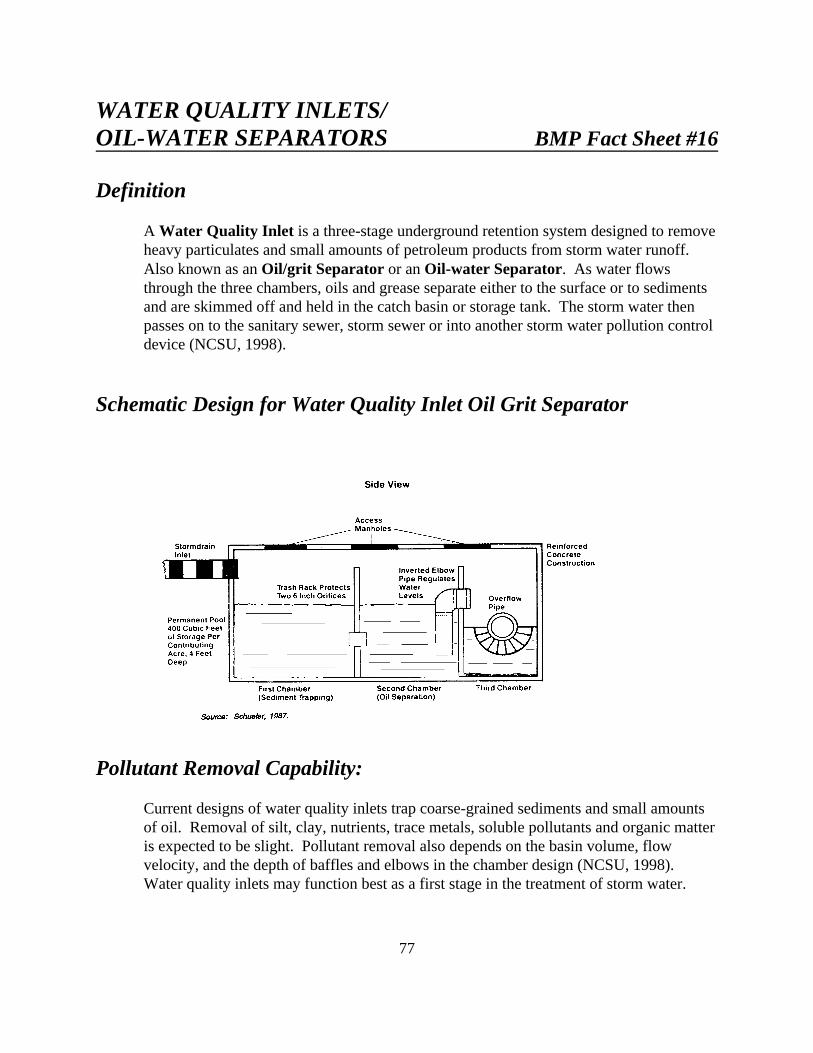
77
WATER QUALITY INLETS/OIL-WATER SEPARATORS BMP Fact Sheet #16
Definition
A Water Quality Inlet is a three-stage underground retention system designed to removeheavy particulates and small amounts of petroleum products from storm water runoff. Also known as an Oil/grit Separator or an Oil-water Separator. As water flowsthrough the three chambers, oils and grease separate either to the surface or to sedimentsand are skimmed off and held in the catch basin or storage tank. The storm water thenpasses on to the sanitary sewer, storm sewer or into another storm water pollution controldevice (NCSU, 1998).
Schematic Design for Water Quality Inlet Oil Grit Separator
Pollutant Removal Capability:
Current designs of water quality inlets trap coarse-grained sediments and small amountsof oil. Removal of silt, clay, nutrients, trace metals, soluble pollutants and organic matteris expected to be slight. Pollutant removal also depends on the basin volume, flowvelocity, and the depth of baffles and elbows in the chamber design (NCSU, 1998). Water quality inlets may function best as a first stage in the treatment of storm water.
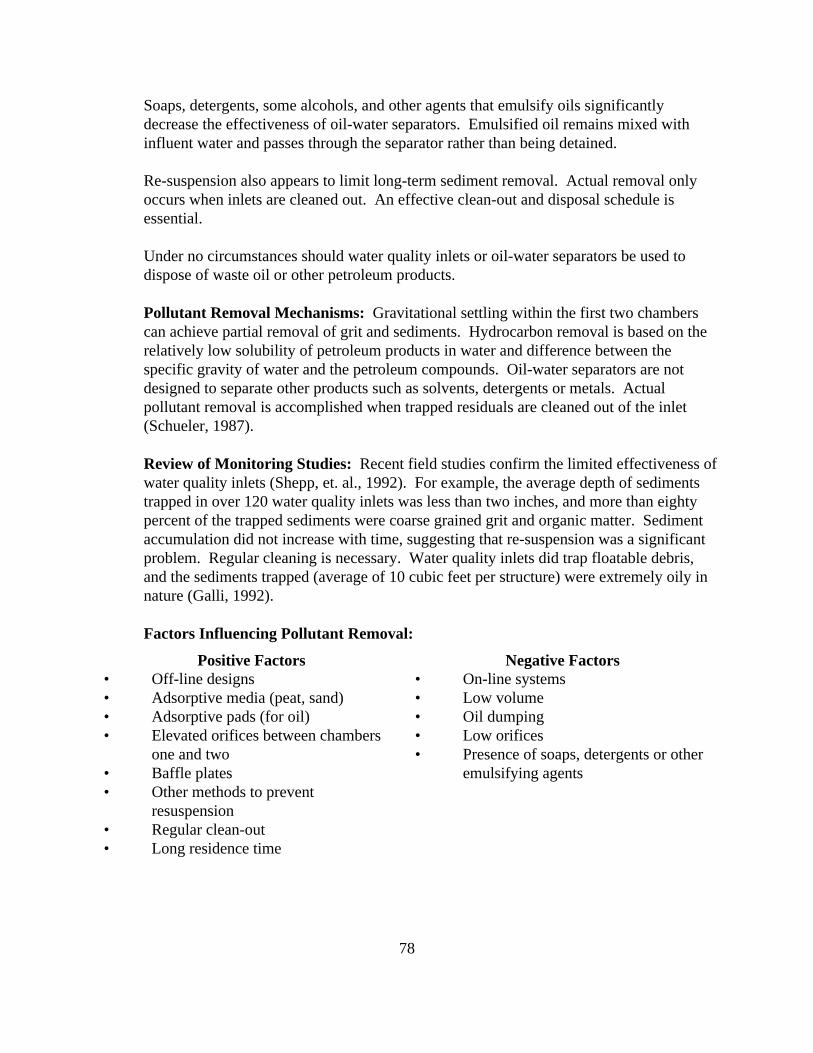
78
Soaps, detergents, some alcohols, and other agents that emulsify oils significantlydecrease the effectiveness of oil-water separators. Emulsified oil remains mixed withinfluent water and passes through the separator rather than being detained.
Re-suspension also appears to limit long-term sediment removal. Actual removal onlyoccurs when inlets are cleaned out. An effective clean-out and disposal schedule isessential.
Under no circumstances should water quality inlets or oil-water separators be used todispose of waste oil or other petroleum products.
Pollutant Removal Mechanisms: Gravitational settling within the first two chamberscan achieve partial removal of grit and sediments. Hydrocarbon removal is based on therelatively low solubility of petroleum products in water and difference between thespecific gravity of water and the petroleum compounds. Oil-water separators are notdesigned to separate other products such as solvents, detergents or metals. Actualpollutant removal is accomplished when trapped residuals are cleaned out of the inlet(Schueler, 1987).
Review of Monitoring Studies: Recent field studies confirm the limited effectiveness ofwater quality inlets (Shepp, et. al., 1992). For example, the average depth of sedimentstrapped in over 120 water quality inlets was less than two inches, and more than eightypercent of the trapped sediments were coarse grained grit and organic matter. Sedimentaccumulation did not increase with time, suggesting that re-suspension was a significantproblem. Regular cleaning is necessary. Water quality inlets did trap floatable debris,and the sediments trapped (average of 10 cubic feet per structure) were extremely oily innature (Galli, 1992).
Factors Influencing Pollutant Removal:
Positive Factors• Off-line designs• Adsorptive media (peat, sand)• Adsorptive pads (for oil)• Elevated orifices between chambers
one and two• Baffle plates• Other methods to prevent
resuspension• Regular clean-out• Long residence time
Negative Factors• On-line systems• Low volume• Oil dumping• Low orifices• Presence of soaps, detergents or other
emulsifying agents

79
Feasibility:
Feasibility: Inlets are restricted to small, highly impervious catchments of two acres orsmaller (such as gas stations, parking lots, fast food outlets, and convenience stores).
Adaptability: Inlets can be adapted to all regions of the country.
Physical Factors: Water quality inlets can be applied in most small developmentsituations, such as parking lots, gas stations, convenience stores, and along some road-ways. The primary limitation is contributing area. Most systems are applied tocontributing watershed areas of two acres or less. The contributing areas typically aremostly or entirely impervious. The inlet must be connected to the storm drain, sanitaryline or to additional storm water treatment measures.
Use In Ultra-Urban Areas: Water quality inlets are frequently applied in ultra urbanareas, where space or storage are not available for other, more effective urban BMPS.
Retrofit Capability: Very limited. Low removal capability coupled with disposalproblems limits the utility of the water quality inlets as a retrofit practice.
Storm Water Management Capability: None. Limited storage of water quality inletscannot meet storm water requirements.
Maintenance:
Inlets require inspections and clean-outs to remove accumulated sediment, oils, floatablesand other pollutants. Wastes removed from these systems should be tested to determineproper disposal methods. The wastes may be hazardous; therefore, maintenance budgetsshould include provisions for proper disposal (NCSU, 1998). Inlets may be difficult toclean and maintain because of its enclosed, underground design (NCSU, 1998). Aboveground designs do exist, though they may not be practical in cold Wyoming winters.
Depending on the type of pollutants entering an oil-water separator and the configurationof the separator, they may be regulated by one or more federal, state or local programs. Abrief description of possible state or federal regulation follows. Be sure to check withappropriate agencies before installing a new facility. Sludge recovered from oil-waterseparators may be, if hazardous, regulated by the Wyoming Department of EnvironmentalQuality (DEQ) and/or the federal Environmental Protection Agency (EPA). Separatorsthat include a separate tank to store waste petroleum products face additional regulationsin that the waste oil tank is regulated as an underground storage tank. Existing oil-waterseparators that are tied to a septic system are considered class V underground injectioncontrol systems and regulated by DEQ. New connections to septic systems are no longer

80
allowed. If you are considering an oil-water separator please contact DEQ and your localgovernment agencies for further information.
Longevity: Longevity of water quality inlets is high. Over ninety-five percent of allinlets are operating as designed in their first five years of operation.
Factors Influencing Longevity: The basic design is very robust, and very few structuralor clogging problems appear to have occurred in the first five years of operation;however, regular clean-outs are not being performed at the vast majority of inlets (Galli,1992). Therefore, the actual pollutant removal is very low at present.
Failure Rates: Nearly four hundred water quality inlets have been installed in theBaltimore/Washington area. Field studies of over one hundred water quality inletsindicated that over ninety-five percent are operating as designed, and very few cloggingproblems have been noted (Galli, 1992). The oldest operating inlets are five years old.
Potential Benefits/Concerns:
Positive Impacts:
• Trapping of floatable trash and debris
• Potential reduction of hydrocarbon load from areas with high traffic/parking use
Negative Impacts:
• Potential toxicity of trapped residuals
• Possibility of pulse hydrocarbon loadings due to re-suspension during large storms
• In some regions, it may be difficult to find environmentally acceptable disposalmethods.

81
STREAMBANK STABILIZATION BMP Fact Sheet #17
Definition:
Streambank Stabilization controls erosion through management of water velocityand/or stream bank stability by natural and manmade controls to decrease bank erosionand sediment loading in waterways. Structural or vegetative means may be usedseparately or together.
Structural Streambank Stabilization decreases erosion by deflecting water energyaway from the streambank. Methods include gabion baskets, rip rap, slope paving, logcribbing as well as in-channel diversion structures (Dodson, 1995).
Vegetative Streambank Stabilization, also known as Bioengineering or SoilBioengineering, describes several methods of establishing vegetative cover byembedding a combination of live, dormant and/or decaying plant materials into banks andshorelines (TBG, Inc., 1998).
Schematic Designs for Streambank Stabilization Controls
Log CribbingSource: Dodson, 1995
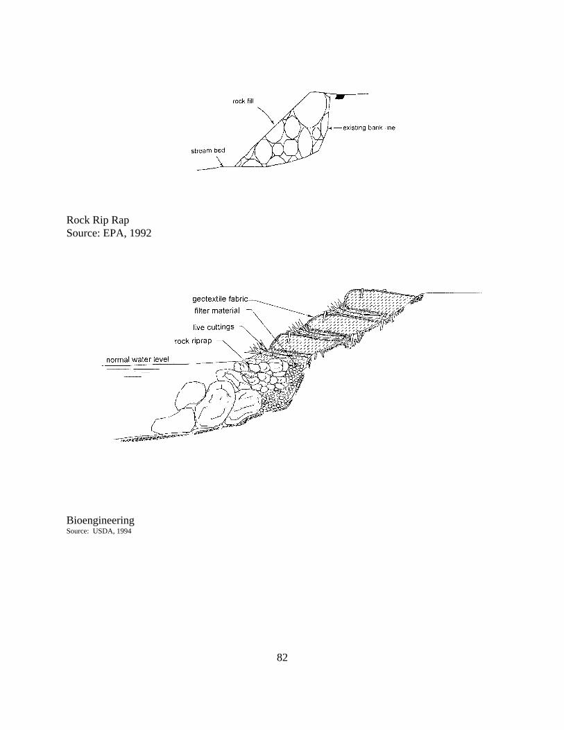
82
Rock Rip RapSource: EPA, 1992
BioengineeringSource: USDA, 1994

83
Pollutant Removal Capability:
Rather than pollutant removal, functions by removing a source of sediment.
Pollutant Removal Mechanisms: Pollutant reduction is achieved through sedimentavoidance by stabilizing streambanks which are subject to erosion during storm events. Vegetative barriers may also filter overland runoff. Additionally, methods that reducevelocity may remove sediment from the stream through deposition.
Feasibility:
Feasibility: Natural or manmade corrective action can be applied to any stream or riverbank where erosion is occurring. In-stream work may require state or federal permits. Use of debris (such as asphalt, refrigerators, etc.) are generally not acceptable for rip rap.
Adaptability: May be used in rural and urban settings.
Development Feasibility: Applicable to areas where erosion has occurred withinstreambanks due to high water velocity and scouring.
Use in Ultra-urban Areas: May be used as a control method where erosion isthreatening property or roadways.
Retrofit Capability: Application to existing problem areas can be made.
Storm Water Management Capability: Indirectly manages storm water by managingthe effects of storm water draining into creeks and rivers (TBG, Inc., 1998).
Maintenance:
Periodic maintenance may be required to maintain effectiveness.
Longevity: Installed and maintained correctly, can provide long term sediment loadavoidance.
Factors Influencing Longevity:
• Sufficient hydrologic investigation and design.
• Use of sufficiently durable materials in construction of manmade controls.
84
• Proper understanding of plant communities when establishing vegetative controlsand use of native species whenever possible.
• Use of stream setbacks restricting development within a specified distance of astreambank can minimize erosion and sediment loading(NCSU, 1998a).
Failure Rates: Vegetative controls may require replanting if initial plantings do not result inadequate cover. Inadequate hydraulic investigation and design or lack of maintenance may resultin failure of manmade or vegetative structures.
Potential Benefits/Concerns:
Positive Impacts:
• Erosion control reduces downstream siltation, increasing downstream waterquality.
• Bioengineering used alone or in concert with mechanical stabilization methodsmay enhance riparian habitat for wildlife (food and cover sources and temperaturecontrol for aquatic and terrestrial animals) (TBG, Inc., 1998)
• Vegetated streambanks may also enhance purification of overland runoff andprovide aesthetic appeal (TBG, Inc., 1998).
Negative Impacts:
• Improperly designed stabilization measures may fail and create erosion abovewhat might otherwise have been expected.
• Structural methods, such as rip rap, gabion baskets, etc., may be consideredunsightly in some areas.
• Manmade structures cannot provide pollutant removal and absorption functions. Natural vegetation may provide some of these functions.

85
MISCELLANEOUS BMPs FORURBAN CONSTRUCTION BMP Fact Sheet #18
Problem
Urban construction results in areas of exposed soils, often in proximity to storm drains,streams or other water bodies. The following BMPs may be used singly or with others toreduce erosion and sedimentation.
Vehicle Tracking Controls
Vehicle tracking controls stabilize construction entrances. The controls typically consist of anasphalt or rock bed at least 50 feet long separating construction areas from public roads. Theasphalt or rock bed provides an area that removes loose sediment from tires of vehicles.
The asphalt or rock bed must be maintained to be effective. Maintenance includes:
• clean paved surfaces by shoveling or sweeping
• add rock to tracking pad as needed
Schematic for vehicle tracking controls
Source: Denver Regional Council of Governments, 1998

86
Inlet Protection
Inlet protection consists of sediment filters around storm drain drop inlets or curb inlets. Construction activities may result in significant amounts of sediments entering storm drainagesystem. Inlet protection should remain in place until the potential for erosion is minimal.
Gravel-filled sand bags may be packed tightly around curb inlets or drop inlets to filter sedimentfrom storm water before it enters a storm drain system. Straw bales or filter fabric may also beused if the situation is such that they can be trenched in.
Inlet protection should not pond water so as to interfere with construction or damage adjacentproperty.
Schematic for Inlet Protection
Source: Denver Regional Council of Governments, 1998

87
Rough-cut Street Controls
Rough-cut street controls are dirt berms or sandbag dikes used to prevent rill, channel and gullyerosion on unpaved surfaces. Controls are particularly essential on streets cut onto slopingsurfaces. Controls work by routing sheet flows off unpaved and unstabilized surfaces tostabilized swales along the sides of roads, other vegetated areas, or detention ponds. Controlsshould be installed at regular intervals along the road (especially sloping roads) and the steeperthe slope, the closer the diversions should be placed. The longer a path storm water has along anunstabilized, sloping surface, the more potential there is for erosion and sediment transport off-site.
Schematic for Rough-cut street controls
Source: Denver Regional Council of Governments, 1998

88
Erosion Control Blankets
Erosion control blankets are used in place of mulch on areas of high velocity runoff and/or steepgrade to control erosion on critical areas by protecting young vegetation.
Erosion control blankets are most useful where:
• Vegetation is likely to grow too slowly to provide adequate cover• High winds render mulch an ineffective control
As with bale check dams and silt fences, proper installation of erosion control blankets isessential for maximum erosion control.
• Erosion control blankets should be installed parallel to the direction of flow• Blanket ends should be buried at least six inches deep• Erosion control blankets should be placed loosely on the soil - not stretched• Edges should be stapled at least every three feet.
Schematic for Erosion Control Blanket Installation
Source: Denver Regional Council of Governments, 1998

89
Temporary Slope Drains
Temporary slope drains are flexible or rigid conduits that extend from the top to the bottom of acut or fill slope. Storm water is routed down the slope through the pipe to a stabilized outlet,avoiding erosion of a bare slope.
Slope drains may be permanent or temporary. Permanent slope drains are often buried, whiletemporary slope drains usually sit on top of the slope.
Careful installation is important; failed slope drains often result in gully erosion on the slope andsedimentation at the slope base.
Schematic for a Slope Drain
Source: Denver Regional Council of Governments, 1998
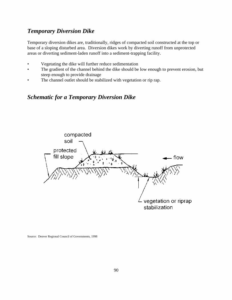
90
Temporary Diversion Dike
Temporary diversion dikes are, traditionally, ridges of compacted soil constructed at the top orbase of a sloping disturbed area. Diversion dikes work by diverting runoff from unprotectedareas or diverting sediment-laden runoff into a sediment-trapping facility.
• Vegetating the dike will further reduce sedimentation• The gradient of the channel behind the dike should be low enough to prevent erosion, but
steep enough to provide drainage• The channel outlet should be stabilized with vegetation or rip rap.
Schematic for a Temporary Diversion Dike
Source: Denver Regional Council of Governments, 1998
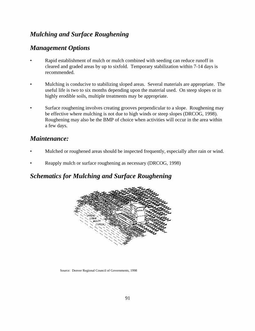
91
Mulching and Surface Roughening
Management Options
• Rapid establishment of mulch or mulch combined with seeding can reduce runoff incleared and graded areas by up to sixfold. Temporary stabilization within 7-14 days isrecommended.
• Mulching is conducive to stabilizing sloped areas. Several materials are appropriate. Theuseful life is two to six months depending upon the material used. On steep slopes or inhighly erodible soils, multiple treatments may be appropriate.
• Surface roughening involves creating grooves perpendicular to a slope. Roughening maybe effective where mulching is not due to high winds or steep slopes (DRCOG, 1998). Roughening may also be the BMP of choice when activities will occur in the area withina few days.
Maintenance:
• Mulched or roughened areas should be inspected frequently, especially after rain or wind.
• Reapply mulch or surface roughening as necessary (DRCOG, 1998)
Schematics for Mulching and Surface Roughening
Source: Denver Regional Council of Governments, 1998

92
Construct Runoff Controls at Staging Areas
Environmental Problem
Staging areas can result in concentrations of hydrocarbons and other pollutants necessary to keepconstruction equipment functioning. Heavy construction traffic and construction clearing cancombine to increase sediment runoff.
Management Options
Line petroleum product storage areas with impermeable barriers (clay, plastic, etc.) and createberms around them to prevent spills. Keep lids closed, tanks off the ground and all productsclearly labeled.
Establish fuel and maintenance staging areas away from all drainage courses and design the areasto control runoff. Install automatic pump shut-off devices on fuel hoses to prevent spills fromoverfilling fuel tanks.
Plan access roads to minimize stream crossing.
Store, cover and isolate construction materials, including chemicals, to prevent runoff ofpollutants and contamination of groundwater. Store only as much chemical (paints, solvents,etc.) as needed for the project. Store chemicals under cover and protected from precipitationrun-on.
Develop and implement a spill control plan.
Maintain and wash equipment in confined areas to control runoff.

93
INDIRECT MANAGEMENT PRACTICES

94
DIRECT RUNOFF AWAYFROM NATURAL CHANNELS BMP Fact Sheet #19
Environmental Problem
Runoff that directly enters a waterway may contain untreated pollutants. Urban runoff typicallycontains such road pollutants as hydrocarbons and metals, pesticides, fertilizers and sediments. While natural wetlands can serve a storm water treatment function, it is EPA policy that theyshall not be used as a storm water treatment option to avoid potential degradation of functioningwetlands.
Management Options
Control of nonpoint sources can reduce the need for other management actions. Wherepossible, locate material stockpiles, borrow areas, access roads and other land disturbingactivities away from critical areas such as steep slopes, highly erodible soils and areas that draindirectly into sensitive water bodies.
Direct runoff into management areas or sanitary sewers that are designed to remove sedimentand/or other pollutants before discharge into surface waters. Roof drains should be directed tovegetated areas rather than storm sewers whenever possible.
The elimination of curbs and gutters has been shown to reduce pollution entering streams andlakes. Because curbs and gutters function as channels for storm water, runoff flows at highvelocities carrying sediment and other pollutants directly to surface waters. Without curbs orgutters, runoff can be spread over vegetated areas where runoff velocities can be reduced andpollutants filtered out by plants or soils. Sections of existing curb can be removed and curboutlets can be installed to flow onto well-vegetated areas. To avoid erosion, flooding and trashaccumulation, the location of curb outlets should be carefully chosen and street cleaningprograms should be modified to maintain these areas (NCSU, 1998).
In low-density developments curb and gutter may be replaced by grassed swales. Properlydesigned, swales may reduce storm water pollutants as well as convey storm water. See BMPFact Sheet #10 for additional information.
Dry-weather flows caused by inappropriate connections to storm sewer systems can contributesignificant pollutants to urban run-off. Some of the more common contributors to non-stormwater flows are infiltration from leaking sanitary lines, direct connection of sanitary or industrialwaste lines, failing septic systems and ground water infiltration. A program to locate and correctcontaminated non-storm water flows may significantly reduce pollutants to surface waters.

95
PROPER DISPOSAL OFACCUMULATED SEDIMENT BMP Fact Sheet #20
Environmental Problem
Sediment removed form traps and basins is often disposed of in areas lacking sediment controls. Without stabilization, such as seeding, these sediments may become resuspended by storm waterrunoff or wind erosion.
Management Options
Placement of spoils sediment upstream of sediment traps.
Sediment spoils used as fill should not be placed within the 100 year floodplain. Fillwithin the floodplain increases velocities and water heights. Sediment would again bedeposited into surface waters.
Land disposal should include seeding or other soils management techniques.

96
PROPER SNOW REMOVAL AND STORAGE BMP Fact Sheet #21
Environmental Problem
Improper snow removal with its associated salts and roadway pollutants can damage roadsidevegetation, increase chloride levels in surface and ground waters and contribute to stratificationof lakes and ponds.
Management Options
Carefully site snow storage areas so that seepage and runoff does not go directly into surface orground waters. Ideally, storage areas should have best management practices applied that serveto capture pollutants in melt water.
Snow removal management can also include management of roadway salts. Use managementsuch as assuring proper application rates and alternatives to salts can have economic, as well asenvironmental benefits. Sand is an alternative that is less harmful to vegetation and aquatic life(NCSU, 1998).
Proper storage of salts in covered areas with impermeable surfaces can also reduceenvironmental impacts from use of road salts. This activity is regulated under the NationalPollution Discharge Elimination System (NPDES) program under a general storm water permit.Installation of a secondary recovery system that collects salty runoff and reapplies it to the pile isan alternative to covering salt or sand/salt piles.

97
HERBICIDE/PESTICIDE/FERTILIZER MANAGEMENT BMP FACT SHEET #22
Environmental Problem
Frequent and/or excessive applications of herbicides, pesiticides, or fertilizers can result inpollutant loadings in surface and ground waters. Discharges to surface or ground waters typicallyoccur due to over application, improper application or application during dormancy (uselessapplication). Non-target plants or organism are exposed both on-site and off-site through watertransportation.
Management Options
Application should be managed to achieve the greatest impact on target species. In some cases,spot verses blanket applications are as effective against target species. Spot use can significantlyreduce pesticide use. Reduced application rates not only decrease the amount of chemicalintroduced to the environment, but may also lower the amount spent on chemical control bybusinesses, homeowners, construction sites and golf courses.
Xeriscaping in arid or semi-arid climates can reduce lawn maintenance, and its resultingchemical use by 50%.
Selection of less toxic, mobile and persistent chemicals with more selective pest control can becombined with a buffer area between the use site and surface waters to reduce the potential foroff-site movement of chemicals.

98
PROTECT NATURAL ANDRIPARIAN VEGETATION BMP Fact Sheet #23
Environmental Problem
Stripping of natural vegetation can result in increased sediment loadings in surface waters. Further, in most instances, native vegetation provides better ground cover than developed plantcommunities.
Removal of riparian habitat and predevelopment flora and fauna results in decreased waterquality. Results may include increased bank cutting, streambed scouring, siltation damage toflora and fauna, increased water temperatures, decreases in dissolved oxygen and changes tostream or river natural flow. Riparian habitat stabilizes streambanks, controlling sediments.
Management Options
In the natural state, shorelines are relatively erosion resistant. Removal of vegetation destabilizessoils resulting in soil loss and sediment loading. If vegetation must be removed, removal shouldbe minimized. Replanting should be made with native species when possible or with otherspecies adapted to the local climate and soils.
Avoid disturbing vegetation on steep slopes or in other critical areas.
Protect natural vegetation with fences, tree armoring, retaining walls or tree walls.
In construction areas, clear only those portions essential for completing site construction usingminimum disturbance/minimum maintenance practices designed to limit clearing and grading aswell as fertilizer, herbicide and pesticide use to redevelop vegetation.
Identify and preserve natural riparian buffers and systems, minimizing additional impacts. Develop community green belts where practical.
Establish riparian buffers or streambank setbacks in areas where surface water quality isdependant upon riparian areas to maintain biological integrity.

99
RECYCLING BMP Fact Sheet #24
Environmental Problem
Improper waste management can increase pollutant loadings in runoff to surface waters andleaching to ground waters. Improper management of household hazardous wastes typicallyoccurs due to unawareness of proper disposal methods or lack of disposal alternatives.
Management Options
Onsite management of yard wastes by homeowners who compost lawn and yard wastes such asleaves, grass clippings and woody wastes. Many municipalities and counties offer compostingfacilities to residents at little or no charge. Composting reduces landfill volumes and the needfor fertilizer by increasing soil nutrients and organic matter.
Developing a convenient, low-cost household hazardous waste collection program encouragesproper disposal of potential pollutants. Products typically collected by these programs are usedoil and antifreeze, unwanted paint and unneeded household chemicals (cleaners, pesticides,herbicides, etc.). Some jurisdictions offer free product exchange programs where homeownerswho drop off unneeded, potentially hazardous materials may also pick up other products that maybe useful to them.
Promote pollution prevention as a means of waste reduction within business and government. Pollution prevention includes recycling as a means of waste reduction, but also includesstrategies to reduce use of hazardous materials such as product substitution. For many businessesrecycling also cuts expenses as input materials are reused or converted to new uses within thesame business or as a product for another business.

100
LITTER REMOVAL BMP Fact Sheet #25
Environmental Problem
Litter enters surface waters via wind and runoff events. Litter and yard wastes can clog stormwater control and conveyance structures making the devices ineffective in storm water pollutantcontrol. Contaminants such as plastics and Styrofoam degrade slowly, while presentingenvironmental risks to fish and wildlife. Pet feces (from dogs, cats, horses, etc.) can contributefecal coliform bacteria to surface waters. Fecal coliforms are a potential human health hazard fordrinking water supplies and contact recreation, such as fishing or swimming.
Management Options
Promote litter removal programs such as Adopt-a-Highway and city/park/river clean-up dayswithin the community. Encourage local pride within the community through civic organizationsto promote individual actions affecting litter removal.
Municipal facilities maintenance programs and commercial and industrial storm water permitteesshould regularly clean inlets, catch basins, outlets and any other necessary areas within stormwater conveyance and collection areas (NCSU, 1998).
Encourage residents to “scoop the poop” when they walk their pets. Some parks in larger citiesprovide bags for dog walkers. Animals, such as horses, cows, etc., should be watered away fromstreams, ponds or lakes to prevent direct entry of fecal material.

101
STREET SWEEPING BMP Fact Sheet #26
Environmental Problem
Particles accumulate along streets and in parking lots that are washed into surface waters bystorm events.
Management Options
Mechanical broom sweepers are effective at removal of curbside litter and street particles greaterthan 400 Fm in size. Vacuum sweepers are more effective on small particles, but can not be usedon wet streets. Removing smaller particles helps to reduce transport of sediment-boundpollutants (NCSU, 1998). In areas such as downtown business districts sweepers may be one ofthe few options for particle removal.
Disposal of street sweeping waste may pose a problem because of possible high levels of lead,zinc, copper and other wastes from automobile traffic. Testing of sweepings may be appropriateto determine disposal alternatives. Some municipalities and industries have found that streetsweepings can be used as cover in sanitary landfills (NCSU, 1998).

102
EXPOSURE REDUCTION BMP Fact Sheet #27
Environmental Problem
Runoff that directly contacts stored materials or inventory can transport pollutants to surface orground water.
Management Options
Industries, municipalities and homeowners can reduce pollution by reducing or eliminatingexposure by simply moving materials indoors or removing materials, products, devices andoutdoor manufacturing activities that may contribute pollution to runoff. Particularly, removal ofrarely used materials that are stored outdoors can be simple and effective (NCSU, 1998).
An inventory of the items on municipal, commercial and industrial sites that are exposed to rainmay provide a useful starting point for exposure-reduction activities. Examples are raw materialstockpiles, stored finished products, and machinery or engines which leak fuel or oil.
The partial or total covering of stockpiled or stored material. loading/unloading areas, orprocessing operations, waste storage areas will reduce or eliminate potential pollutants in runoff. For sites that are only partially covered directing storm water “run-on” away from materials willalso reduce pollutant loading in storm water (NCSU, 1998).
Changes in inventory management to a “just-in-time” (JIT) method will reduce the amount ofmaterials exposed to storm water at any given time. JIT uses precise scheduling of materials andproducts in and out of a site to keep the amount of raw materials and products on hand to aminimum, reducing waste, storage costs and potential pollutants exposed to storm water (NCSU,1998).
Good housekeeping involves maintaining equipment to be free of leaks, removing emptymaterials containers, removing trash, sweeping of parking lots and roads, disposal of unusedequipment. All these activities reduce exposure of pollutants to storm water (NCSU, 1998).
Training and prevention programs prepare employees to prevent spills and to respond quicklywhen spills do occur (NCSU, 1998).

103
EDUCATION BMP Fact Sheet #28
Much of urban nonpoint source (NPS) pollution is theresult of cumulative actions by many individuals,businesses and industries. The reduction of NPSpollution, in turn, depends the choices and actions ofindividuals, businesses, and industries. Oftenindividuals and business owners are not aware that stormdrains deliver runoff to nearby waterbodies withouttreatment. Nor are many aware that some of theircommon practices (over-fertilization, material storage,etc.) may contribute to pollution. Community educationis one of the most effective ways of preventing storm water pollution.
Businesses, developers, and homeowners are all part of the NPS pollution puzzle and publicawareness programs must be tailored to meet the individual needs and interests of each segmentof the community. For example, programs for homeowners might focus on the use of lawnchemicals and disposal of common household wastes such as motor oil, cleaners, and herbicides. Business-oriented programs might stress good housekeeping and chemical reuse strategies. Anyeducation program should provide not only concrete information about pollutant sources andcauses, but also specific information about storing, using, and disposing of materials which maycause storm water pollution.
Involve community groups when possible. School or youth groups may be interested instenciling storm drains with a message such as, “Dump No Waste; Drains to River.” Educationalmaterials or presentations can be made available at a variety of community forums such as fairs,Earth Day events, town meetings, service organizations, and local festivals. “Adopt-a-River”type programs may be adapted to include educational efforts on the effects of pollution in stormwater runoff.
Information on storm water best management practices and educational materials are availablefrom many sources. Federal, state and many local governments may have written material orinformation on internet web pages. Many private organizations are also involved in improvingurban water quality and public education. References to some of these groups may be found inthe reference sections of this manual or on the internet. The Wyoming Department ofEnvironmental Quality also has water-quality grants available annually for demonstration orassessments projects and educational programs. Depending on the source of the grants they maybe awarded to state or local government units, schools, non-governmental organizations (clubs,conservation groups, et cetera) or individuals. Demonstration and assessment types of projectsmust have an educational component. For more information on grant availability andrequirements contact the Nonpoint Source Program Coordinator at the Wyoming Department ofEnvironmental Quality, Water Quality Division, 307-777-7781.

104
Building awareness of, not only the problems, but also the solutions to NPS pollution is criticalto building public support for efforts to control pollution. Programs and ordinances will be moreeffective with community understanding and participation.

105
APPENDIX A
Additional Information

106
Appendix A Table 1Advantages and Disadvantages of Management Practices
Management Practice Advantages Disadvantages Comparative Cost 1
Infiltration Basin(BMP #6, Page 39)
C Provides ground water recharge C Can serve large developments C High removal capability for particulate
pollutants and moderate removal for solublepollutants
C When basin works, it can replicatepredevelopment hydrology more closely thanother BMP options
C Basins provide more habitat value than otherinfiltration systems
C@ Possible risk of contaminating groundwaterC@ Only feasible where soil is permeable and there
is sufficient depth to rock and water tableC@ Fairly high failure rateC@ If not adequately maintained, can be an
eyesore, breed mosquitoes, and createundesirable odors
C Regular maintenance activities cannot preventrapid clogging of infiltration basins
Construction cost moderate butrehabilitation cost high
Infiltration Trench(BMP #5, Page 36)
C Provides ground water recharge C Can serve small drainage areas C Can fit into medians, perimeters, and other
unused areas of a development siteC Helps replicate predevelopment hydrology,
increases dry weather baseflow, and reducesbankfull flooding frequency
C Possible risk of contaminating groundwaterC Only feasible where soil is permeable and there
is sufficient depth to rock and water tableC Since not as visible as other BMPS, less likely
to be maintained by residentsC Requires significant maintenance
Cost-effective on smaller sites. Rehabilitation costs can beconsiderable.
Vegetative Filter Strip(BMP #11, Page 61)
C Low maintenance requirementsC Can be used as parl of the runoff conveyance
system to provide pretreatmentC Can effectively reduce particulate pollutant
levels in areas where runoff velocity is low tomoderate
C Provides excellent urban wildlife habitat C Economical
C Often concentrates water, which significantlyreduces effectiveness
C Ability to remove soluble pollutants highlyvadable
C Limited feasibility in highly urbanized areaswhere runoff velocities are high and flow isconcentrated
C Requires periodic repair, regrading,andsediment removal to prevent channelization
Low
Grassed Swale(BMP #10, Page 55)
C Requires minimal land areaC Can be used as part of the runoff conveyance
system to provide pretreatmentC Can provide sufficient runoff control to replace
curb and gutter in single-family residentialsubdivisions and on highway medians
C Economical
C Low pollutant removal ratesC Leaching from culverts and fertilized lawns
may actually increase the presence of tracemetals and nutrients
Low compared to curb andgutter

Management Practice Advantages Disadvantages Comparative Cost 1
107
Porus Pavement(BMP #7, Page 44)
C Provides ground water rechargeC Provides water quality control without
additional consumption of land C Can provide peak flow control. High removal
rates for sediment, nutrients, organic matter, andtrace metals
C When operating properly can replicatepredevelopment hydrology
C Eliminates the need for storm water drainage,conveyance, and treatment systems off-site
C Requires regular maintenanceC Possible risk of contaminating groundwater
C Only feasible where soil is permeable, there issufficient depth to rock and water table, andthere are gentle slopes
C Not suitable for areas with hightraffic volume
C Need extensive feasibility tests, inspections,and very high level of constructionworkmanship (Schueler. 1987)
C High failure rate due to cloggingC@ Not suitable to serve large-off-site
areas without pretreatment
Cost-effective compared toconventional asphalt whenworking properly
Concrete Grid Pavement(BMP #8, Page 48)
C Can provide peak flow controlC Provides ground water rechargeC Provides water quality control without
additional consumption of land
C Requires regular maintenanceC Not suitable for area with high traffic volumeC Possible risk of contaminating groundwaterC Only feasible where soil is permeable, there is
sufficient depth to rock and water table, andthere are gentle slopes
Information not available
Filtration Basin(BMP #6, Page 39)
C Ability to accommodate medium-sizedevelopment (3-80 acres)
C Flexibility to provide or not providegroundwater recharge
C Can provide peak volume control
C Requires pretreatment of storm water throughsedimentation to prevent filter media fromprematurely clogging
Information not available
Water Quality Inlet Catch Basins(BMP #16, Page 77)
C Provide high degree of removal efficiencies forlarger particles and debris as pretreatment
C Require minimal land areaC Flexibility to retrofit existing small drainage
areas and applicable to most urban areas
C Not feasible for drainage area greater than 1acre
C Marginal removal of small particles, heavymetals, and organic pollutants
C Not effective as water quality control forintense storms
C Minimal nutrient removal
Information not available
Water Quality Inlet Catch Basinswith Sand Filter(BMPs #9, 16, Pages 51 & 77)
C Provide high removal efficiencies of particulates
C Require minimal land areaC Flexibility to retrofit existing small drainage
areasC Higher removal of nutrients as compared to
catch basins and oil/grid separator
C Not feasible for drainage areas greater than 5acres
C Only feasible for areas that are stabilized andhighly impervious
C Not effective as water quality control forintense storms
Information not available
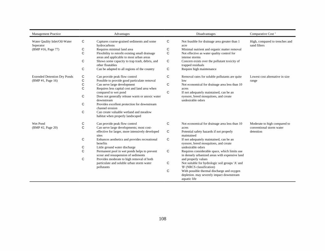
Management Practice Advantages Disadvantages Comparative Cost 1
108
Water Qaulity Inlet/Oil-WaterSeperator(BMP #16, Page 77)
C Captures coarse-grained sediments and somehydrocarbons
C Requires minimal land areaC Flexibility to retrofit existing small drainage
areas and applicable to most urban areasC Shows some capacity to trap trash, debris, and
other floatablesC Can be adapted to all regions of the country
C Not feasible for drainage area greater than 1acre
C Minimal nutrient and organic matter removalC Not effective as water quality control for
intense storms C Concern exists over the pollutant toxicity of
trapped residuals C Require high maintenance
High, compared to trenches andsand filters
Extended Detention Dry Ponds(BMP #1, Page 16)
C Can provide peak flow controlC Possible to provide good particulate removalC Can serve large developmentC Requires less capital cost and land area when
compared to wet pondC Does not generally release warm or anoxic water
downstreamC Provides excellent protection for downstream
channel erosionC Can create valuable wetland and meadow
habitat when properly landscaped
C Removal rates for soluble pollutants are quitelow
C Not economical for drainage area less than 10acres
C If not adequately maintained, can be aneyesore, breed mosquitoes, and createundesirable odors
Lowest cost altemative in sizerange
Wet Pond(BMP #2, Page 20)
C Can provide peak flow controlC Can serve large developments; most cost-
effective for larger, more intensively developedsites
C Enhances aesthetics and provides recreationalbenefits
C Little ground water dischargeC Permanent pool in wet ponds helps to prevent
scour and resuspension of sedimentsC Provides moderate to high removal of both
particulate and soluble urban storm waterpollutants
C Not economical for drainage area less than 10acres
C Potential safety hazards if not properlymaintained
C If not adequately maintained, can be aneyesore, breed mosquitoes, and createundesirable odors
C Requires considerable space, which limits usein densely urbanized areas with expensive landand properly values
C Not suitable for hydrologic soil groups 'A' and'B' (NRCS classification)
C With possible thermal discharge and oxygendepletion. may severely impact downstreamaquatic life
Moderate to high compared toconventional storm waterdetention

Management Practice Advantages Disadvantages Comparative Cost 1
109
Extended Detention Wet Pond(BMP #4, Page 29)
C Can provide peak flow controlC Can serve large developments; most cost-
effective for larger, more intensively developedsites
C Enhances aesthetic and provide recreationalbenefits
C Permanent pool in wet ponds helps to preventscour and resuspension of sediments
C Provides better nutrient removal when comparedto wet pond
C Not economical for drainage areas less than 10acres
C Potential safety hazards if not properlymaintained
C If not adequately maintained, can be aneyesore, breed mosquitoes, and createundesirable odors
C Requires considerable space, which limits usein densely urbanized areas with expensive landand property values
C Not suitable for hydrologic soil groups 'A' and'B'(NRCS classification)
C With possible thermal discharge and oxygendepletion, may severely impact downstreamaquatic life
Constructed Storm waterWetland(BMP #3, Page 24)
C Can serve large developments; most cost-effective for larger, more intensively developedsites
C Provides peak flow controlC Enhances aesthetics and provides recreational
benefitsC The marsh fringe also protects shoreline from
erosionC Permanent pool in wet ponds helps to prevent
scour and resuspension of sedimentsC Has high pollutant removal capability
C Not economical for drainage area less than 10acres
C Potential safety hazards if not properlymaintained
C If not adequately maintained can be aneyesore, breed mosquitoes, and createundesirable odors
C Requires considerable space, which limits usein densely urbanized areas with expensive landand property values
C With possible thermal discharge and oxygendepletion, may severely impact downstreamaquatic life
C May contribute to nutrient loadings during die-down periods of vegetation
Marginally higher than wetponds

110
Appendix A Table 2Estimated Mean Runoff Concentrations for Land Uses,
Based on the Nationwide Urban Runoff Program(Whalen and Cullum, 1989)
Parameter Residential Commercial Industrial
TKN (mg/l) 0.23 1.5 1.6
NO3+NO2 1.8 0.8 0.93
Total P (mg/l) 0.62 2.29 0.42
Copper (Fg/l) 56 50 32
Zinc (Fg/l) 254 418 1,063
Lead (mg/l) 293 203 115
COD (mg/l) 103 84 62
TSS (mg/l) 228 168 108
BOD (mg/l) 13 14 62
TKN (mg/l) - Total Kjeldahl nitrogen, a measure of ammonia and organic nitrogen present in a sample.
NO3 + NO2 - Nitrate (NO3) plus Nitrite (NO2), a measure of inorganic nitrogen present in a sample.
Total P - Total phosphorus in a sample.
TSS - Total Suspended Solids, a measure of the amount of suspended particles (organic and inorganic)that are small enough to remain suspended in water.
BOD - Biological Oxygen Demand, refers to the amount of oxygen that will be consumed by biologicaldegradation of organic matter. A high BOD indicates a large amount of biodegradable organic matterthat can be decomposed, primarily through microbial action. Water bodies with high BOD may lacksufficient oxygen (i.e., low dissolved oxygen, DO) to support various aquatic species.
COD - Chemical Oxygen Demand, an indirect measure of the organic content (biodegradable and non-biodegradable) of a sample. The test measures the amount of oxygen consumed by a strong oxidizingagent introduced to the sample. The higher the number, the greater the organic content. Waters withhigh COD often have low dissolved oxygen and impaired habitat for aquatic life.

111
Appendix A Table 3Regional, Site Specific, and Maintenance Considerations for Structural
Practices to Control Sediments in Storm Water Runoff
BMP Option Size ofDrainage Area
SiteRequirement
RegionalRestrictions
MaintenanceBurdens
Longevity
InfiltrationBasins(BMP #6, p. 39)
Moderate tolarge
Deep permeablesoils
Arid & coldregions
High Low
InfiltrationTrenches(BMP #5, p. 34)
Moderate Same as for Infiltration Basins
Vegetated FilterStrips(BMP #11, p. 61)
Small Low densityareas with lowslopes
Arid & coldregions
Low Low if poorlymaintained
Grassed Swales(BMP #10, p.55)
Small Low densityareas with<15% slopes
Arid & coldregions
Low High ifmaintained
Porus Pavement(BMP #7, p. 44)
Small Deep permeablesoils, lowslopes, andrestricted traffic
Arid & coldregions or highwind erosionrates
High low
Concrete GridPavement(BMP #8, p. 48)
Small Same as forPorousPavement
Extremefreeze/thaw orhigh winderosion
Moderate tohigh
High
FiltrationBasins & SandFilters(BMP #9, p. 51)
Widelyapplicable
Widelyapplicable
Arid & coldregions
Moderate Low tomoderate
Water QualityInlets(BMP #16, p. 77)
Small Imperviouscatchments
Few restrictions Cleaned twice ayear
High
ExtendedDetentionPonds(BMP #1, p. 16)
Moderate tolarge
Deep soils Few restrictions Dry ponds haverelatively highburdens
High
Wet Ponds(BMP #2, p. 20)
Moderate tolarge
Deep soils Arid regions Low High
ConstructedStorm WaterWetlands(BMP #3, p. 24)
Moderate tolarge
Poorly drainedsoils, space maybe limiting
Arid regions Annualharvesting ofvegetation
High

112
Appendix A Table 4Effectiveness of Management Practices for Control
of Runoff from Nearly Developed AreasManagement Practices
Removal Efficiency (%) Factors
TSS TP TN COD Pb Zn
InfiltrationBasin(BMP #6, p. 39)
Average:Reported Range:Probable Range: NRCS Soil Group A NRCS Soil Group BNo. Values Considered:
7545-100
60-10050-807
6545-100
60-10050-807
6045-100
60-10050-807
6545-100
60-10050-804
6545-100
60-10050-804
6545-100
60-10050-804
Soil percolationrates
Basin surface area
Storage volume
InfiltrationTrench(BMP #5, p. 34)
Average:Reported Range:Probable Range: NRCS Soil Group A NRCS Soil Group BNo. Values Considered:
7545-100
60-10050-909
6045-100
60-10050-909
5545-100
60-10050-909
6545-100
60-10050-904
6545-100
60-10050-904
65 45-100
60-10050-904
Soil percolationrates
Trench surfacearea
Storage volume
VegetativeFilter Strip(BMP #11, p. 61)
Average:Reported Range:Probable Range:No. Values Considered:
6520-8040-907
400-9530-804
400-7020-603
400-80
2
4520-9030-803
6030-9020-503
Runoff Volume
Slope
Soil infiltrationrates
Vegetative Cover
Buffer length
Grass Swale(BMP #10, p. 55)
Average:Reported Range:Probable Range:No. Values Considered:
600-10020-4010
200-10020-408
100-4010-304
2525
1
703-1010-2010
6050-6012-207
Runoff volume
Slope
Soil infiltrationrates
Vegetative cover
Swale Length
Swale geometry
PorusPavement(BMP #7, p. 44)
Average:Reported Range:Probable Range:No. Values Considered:
9085-9560-902
656560-902
8580-8560-902
808060-902
10010060-902
10010060-902
Percolation rates
Storage volume
ConcreteGridPavement(BMP #8, p. 48)
Average:Reported Range:Probable Range:No. Values Considered:
9065-10060-902
9065-10060-902
9065-10060-902
9065-10060-902
9065-10060-902
9065-10060-902
Percolation rates
Sand Filter/FiltrationBasin(BMPs #6 &9, p. 39 &51)
Average:Reported Range:Probable Range:No. Values Considered:
8060-9560-9010
500-900-806
3520-4020-407
5545-7040-703
6030-9040-805
6550-8040-805
Treatment volume
Filtration media

Management Practices
Removal Efficiency (%) Factors
TSS TP TN COD Pb Zn
113
WaterQuality Inlet(BMP #16, p. 77)
Average:Reported Range:Probable Range:No. Values Considered:
350-9510-253
55-105-101
205-555-102
55-105-101
155-255-252
55-105-101
Maintenance
Sedimentationstorage volume
WaterQuality Inletwith SandFilter(BMP#9,16, p. 51,77)
Average:Reported Range:Probable Range:No. Values Considered:
8075-8570-901
nana
0
3530-4530-451
5545-7040-701
8070-9070-901
6550-8050-801
Sedimentationstorage volume
Depth of filtermedia
Oil/GritSeperator(BMP #16, p. 77)
Average:Reported Range:Probable Range:No. Values Considered:
150-2510-252
55-105-101
55-105-101
55-105-101
1510-2510-251
55-105-101
Sedimentationstorage volume
Ouletconfigurations
ExtendedDetentionDry Pond(BMP #1, p. 16)
Average:Reported Range:Probable Range:No. Values Considered:
455-9070-906
2510-5510-606
3020-6020-604
200-4030-405
5025-6520-604
20(-40)-6540-605
Storage volume
Detention time
Pond shape
Wet Pond(BMP #2, p. 20)
Average:Reported Range:Probable Range:No. Values Considered:
60(-30)-9150-9018
4510-8520-9018
355-8510-909
405-9010-907
7510-9510-9513
6010-9520-9513
Pond volume
Pond shape
ExtendedDetentionWet Pond(BMP #2, p. 20)
Average:Reported Range:Probable Range:No. Values Considered:
8050-10050-953
6550-8050-903
555510-901
nana10-900
404010-951
202020-951
Pond volume
Pond shape
Detention time
ConstructedStorm waterWetlands(BMP #3, p. 23)
Average:Reported Range:
Probable Range:No. Values Considered:
65(-20)-10050-9023
25(-125)-100(-5)-8024
20(-15)-40
0-408
5020-80
2
6530-95
30-9510
35(-30)-80
8
Storage volume
Detention time
Pool shape
Wetland’s biota
Seasonal variation
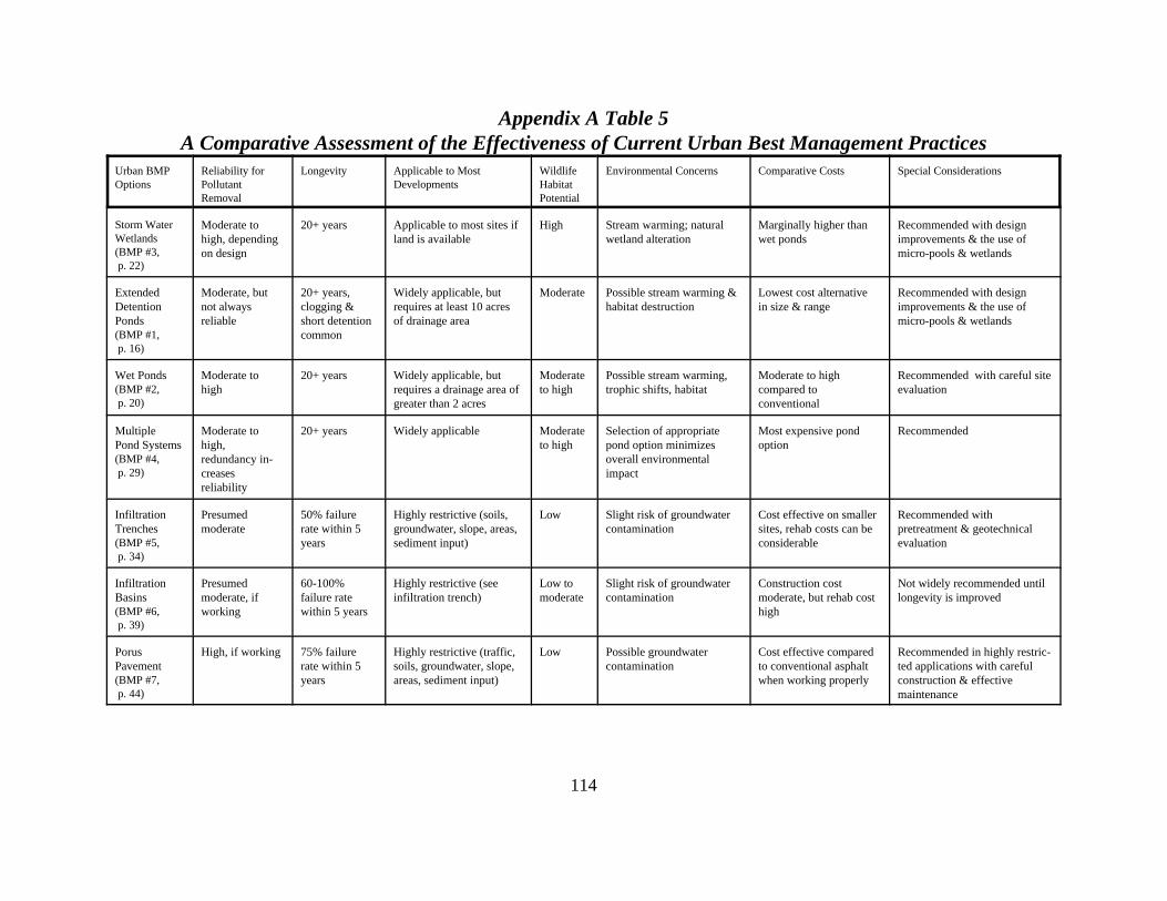
114
Appendix A Table 5A Comparative Assessment of the Effectiveness of Current Urban Best Management Practices
Urban BMPOptions
Reliability forPollutantRemoval
Longevity Applicable to MostDevelopments
WildlifeHabitatPotential
Environmental Concerns Comparative Costs Special Considerations
Storm WaterWetlands(BMP #3, p. 22)
Moderate tohigh, dependingon design
20+ years Applicable to most sites ifland is available
High Stream warming; naturalwetland alteration
Marginally higher thanwet ponds
Recommended with designimprovements & the use ofmicro-pools & wetlands
ExtendedDetentionPonds(BMP #1, p. 16)
Moderate, butnot alwaysreliable
20+ years, clogging &short detentioncommon
Widely applicable, butrequires at least 10 acresof drainage area
Moderate Possible stream warming &habitat destruction
Lowest cost alternativein size & range
Recommended with designimprovements & the use ofmicro-pools & wetlands
Wet Ponds(BMP #2, p. 20)
Moderate tohigh
20+ years Widely applicable, butrequires a drainage area ofgreater than 2 acres
Moderateto high
Possible stream warming,trophic shifts, habitat
Moderate to highcompared toconventional
Recommended with careful siteevaluation
MultiplePond Systems(BMP #4, p. 29)
Moderate tohigh,redundancy in-creasesreliability
20+ years Widely applicable Moderateto high
Selection of appropriatepond option minimizesoverall environmentalimpact
Most expensive pondoption
Recommended
InfiltrationTrenches(BMP #5, p. 34)
Presumedmoderate
50% failurerate within 5years
Highly restrictive (soils,groundwater, slope, areas,sediment input)
Low Slight risk of groundwatercontamination
Cost effective on smallersites, rehab costs can beconsiderable
Recommended withpretreatment & geotechnicalevaluation
InfiltrationBasins(BMP #6, p. 39)
Presumedmoderate, ifworking
60-100%failure ratewithin 5 years
Highly restrictive (seeinfiltration trench)
Low tomoderate
Slight risk of groundwatercontamination
Construction costmoderate, but rehab costhigh
Not widely recommended untillongevity is improved
PorusPavement(BMP #7, p. 44)
High, if working 75% failurerate within 5years
Highly restrictive (traffic,soils, groundwater, slope,areas, sediment input)
Low Possible groundwatercontamination
Cost effective comparedto conventional asphaltwhen working properly
Recommended in highly restric-ted applications with carefulconstruction & effectivemaintenance
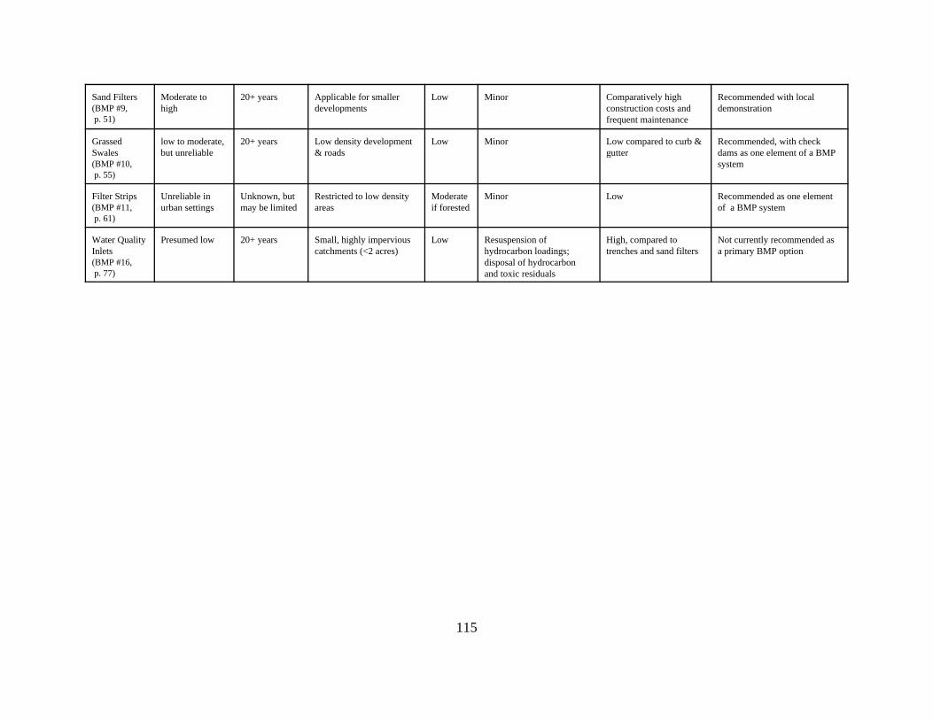
115
Sand Filters(BMP #9, p. 51)
Moderate tohigh
20+ years Applicable for smallerdevelopments
Low Minor Comparatively highconstruction costs andfrequent maintenance
Recommended with localdemonstration
GrassedSwales(BMP #10, p. 55)
low to moderate,but unreliable
20+ years Low density development& roads
Low Minor Low compared to curb &gutter
Recommended, with checkdams as one element of a BMPsystem
Filter Strips(BMP #11, p. 61)
Unreliable inurban settings
Unknown, butmay be limited
Restricted to low densityareas
Moderateif forested
Minor Low Recommended as one elementof a BMP system
Water QualityInlets(BMP #16, p. 77)
Presumed low 20+ years Small, highly imperviouscatchments (<2 acres)
Low Resuspension ofhydrocarbon loadings;disposal of hydrocarbonand toxic residuals
High, compared totrenches and sand filters
Not currently recommended asa primary BMP option

116
Appendix A Table 6ESC Quantitative Effectiveness for Sediment Control Practices
Practice Design Constraints or Purpose Percent Removal of TSS Useful Life(years)
Sediment Basin(BMP #12, p.66)
Minimum drainage area = 5 acres,maximum drainage area = 100 acres
Average: 70%Observed range: 55%-100%
2
Sediment Trap(BMP #12, p.66)
Maximum drainage area = 5 acres Average: 60%Observed range: (-7%)-100%
1.5
Silt Fence(BMP #14, p.71)
Maximun drainage area = .5 acre per100 feet of fence. Not to be used inconcentrated flow areas.
Average: 70%Observed range: 0%-100% Sand: 80%-99% Silt-Loam: 50%-80% Silt-Clay-Loam: 0%-20%
0.5
Straw BaleBarrier(BMP #14, p.71)
Maximum drainage area = 0.25 acre per100 feet of barrier. Not to be used inconcentrated flow areas.
Average: 70%Observed range: 70%
0.25
Inlet Protection(BMP #18, p.85)
Protect storm drain inlet. Average: NAObserved range: NA
1
ConstructionEntrance(BMP #18, p.85)
Removes sediment from vehicle wheels. Average: NAObserved range: NA
2
Vegetative FilterStrip(BMP #11, p.61)
Must have sheet flow. Average: 70%Observed range: 20%-80%
2
NA = Not availablea Usefull life estimated as length of construction project ( 2 years) b Trap volume = 1800 cf/ac (.5 inches run-off per acre)

117
Appendix A Table 7Pollutant Concentrations in Highway Runoff
Pollutant Event Mean Concentration forHighways with Fewer than
30,000 Vehicles per day (mg/L)
Event Mean Concentration forHighways with More than
30,000 Vehicles per day (mg/L)
Total Suspended Solids* 41 142
Volatile Suspended Solids 12 39
Total Organic Carbon 8 25
Chemical Oxygen Demand* 49 114
Nitrite and Nitrate* 0.46 0.76
Total Kjeldahl Nitrogen* 0.87 1.83
Phosphate Phosphorus 0.16 0.40
Copper (Cu) 0.022 0.054
Lead (Pb) 0.080 0.400
Zinc (Zn) 0.080 0.329Event Mean Concentrations are for the 50% median site.
*These terms are defined in Appendix A, Table 2.
Volatile Suspended Solids (VSS) - That portion of Total Suspended Solids that contain carbon and arecombustible. VSSs may originate from incompletely combusted vehicle exhaust particulates or theproducts of tire wear.
Total Organic Carbon (TOC) - The total amount of organically bound carbon in a sample. Materialssuch as fuels, oils, and pesticides contain organically bound carbon.
Phosphate Phosphorus - The amount of phosphorus present as phosphate (PO4) in a sample.
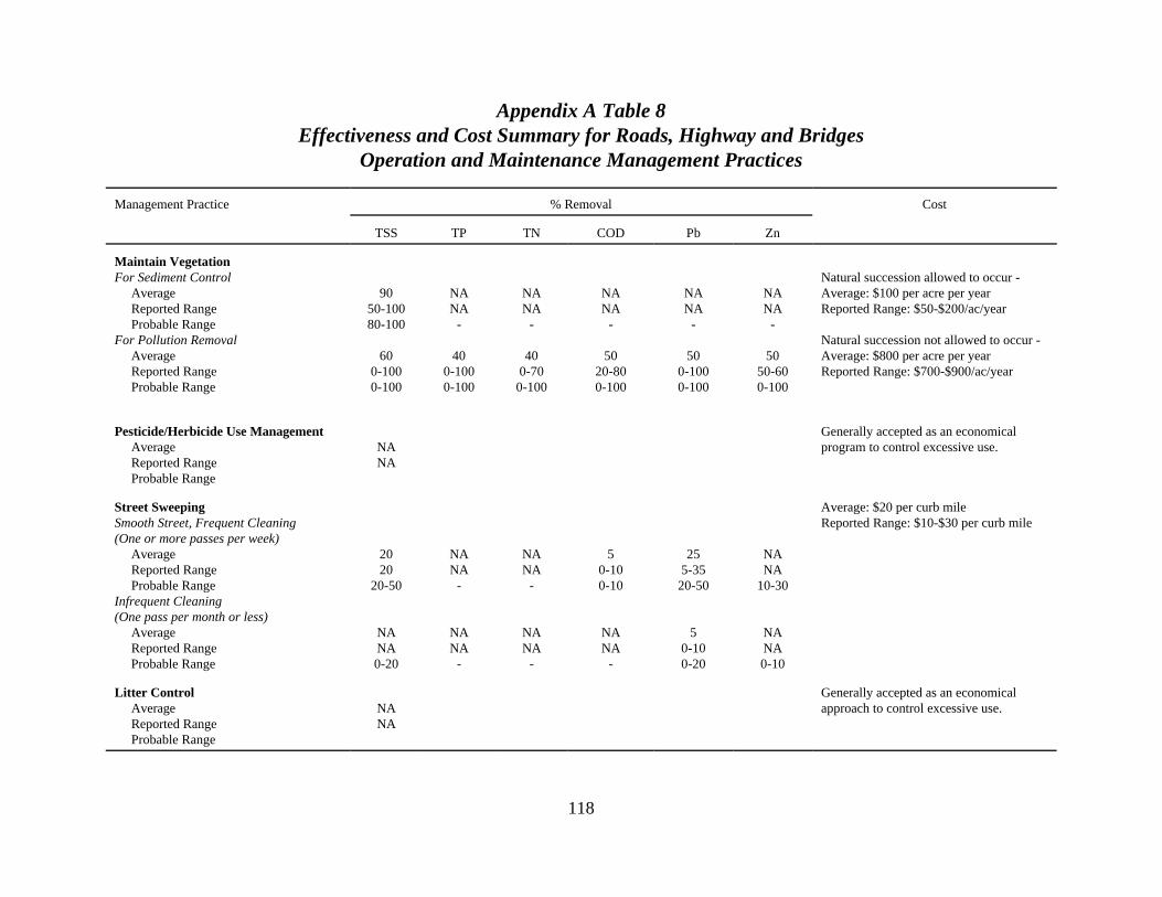
118
Appendix A Table 8Effectiveness and Cost Summary for Roads, Highway and Bridges
Operation and Maintenance Management Practices
Management Practice % Removal Cost
TSS TP TN COD Pb Zn
Maintain VegetationFor Sediment Control Average Reported Range Probable RangeFor Pollution Removal Average Reported Range Probable Range
9050-10080-100
600-1000-100
NANA
-
400-1000-100
NANA
-
400-70
0-100
NANA
-
5020-800-100
NANA
-
500-1000-100
NANA
-
5050-600-100
Natural succession allowed to occur - Average: $100 per acre per yearReported Range: $50-$200/ac/year
Natural succession not allowed to occur - Average: $800 per acre per yearReported Range: $700-$900/ac/year
Pesticide/Herbicide Use Management Average Reported Range Probable Range
NANA
Generally accepted as an economicalprogram to control excessive use.
Street SweepingSmooth Street, Frequent Cleaning(One or more passes per week) Average Reported Range Probable RangeInfrequent Cleaning (One pass per month or less) Average Reported Range Probable Range
2020
20-50
NANA0-20
NANA
-
NANA
-
NANA
-
NANA
-
50-100-10
NANA -
255-35
20-50
50-100-20
NANA
10-30
NANA0-10
Average: $20 per curb mileReported Range: $10-$30 per curb mile
Litter Control Average Reported Range Probable Range
NANA
Generally accepted as an economicalapproach to control excessive use.
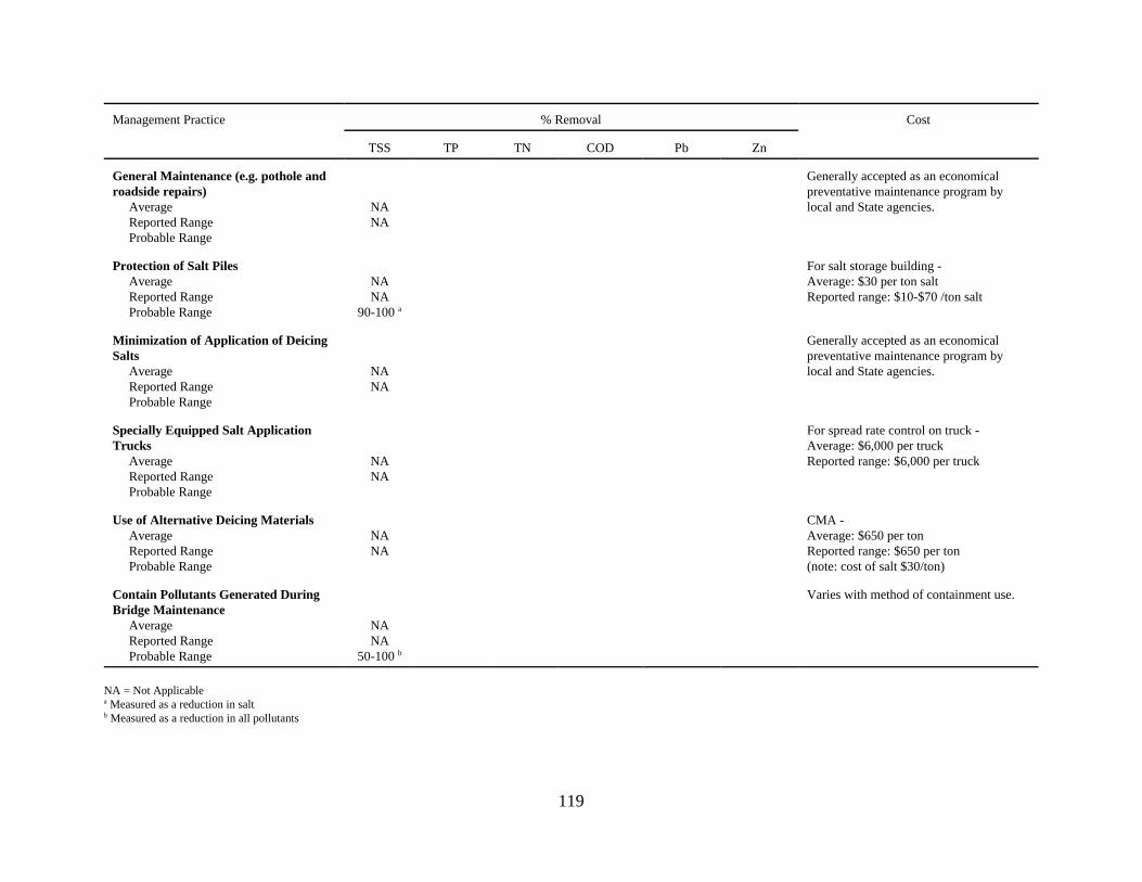
Management Practice % Removal Cost
TSS TP TN COD Pb Zn
119
General Maintenance (e.g. pothole androadside repairs) Average Reported Range Probable Range
NANA
Generally accepted as an economicalpreventative maintenance program bylocal and State agencies.
Protection of Salt Piles Average Reported Range Probable Range
NANA
90-100 a
For salt storage building - Average: $30 per ton saltReported range: $10-$70 /ton salt
Minimization of Application of DeicingSalts Average Reported Range Probable Range
NANA
Generally accepted as an economicalpreventative maintenance program bylocal and State agencies.
Specially Equipped Salt ApplicationTrucks Average Reported Range Probable Range
NANA
For spread rate control on truck - Average: $6,000 per truckReported range: $6,000 per truck
Use of Alternative Deicing Materials Average Reported Range Probable Range
NANA
CMA - Average: $650 per tonReported range: $650 per ton(note: cost of salt $30/ton)
Contain Pollutants Generated DuringBridge Maintenance Average Reported Range Probable Range
NANA
50-100 b
Varies with method of containment use.
NA = Not Applicablea Measured as a reduction in saltb Measured as a reduction in all pollutants

120
Appendix A Figure 1Restrictions for BMP Application Based on Soil Permeability
Appendix A Figure 2Feasible BMPs for Different Watershed Sizes

121
GLOSSARYADSORPTION - Adhesion of the molecules of a gas, liquid or dissolved substance to a surface. Adsorption differs from absorption in that absorption is the assimilation or incorporation of a gas, liquidor dissolved substance into another substance.
ADJUSTABLE GATE VALVE - A knife gate valve, activated by a handwheel, used to control theinternal diameter of reverse slope pipes or allow rapid opening of the pond drain pipe.
AGGREGATE - Term for the stone or rock gravel needed to fill in an infiltration BMP such as a trenchor porous pavement. Clean-washed aggregate is simply aggregate that has been washed clean so that nosediment is associated with.
AQUATIC BENCH - A ten to fifteen foot bench around the inside perimeter of a permanent pool that isapproximately one foot deep. Normally vegetated with emergent plants, the bench augments pollutantremoval, provides habitat, conceals trash and water level drops, and enhances safety.
ARTIFICIAL MARSH CREATION - Simulation of natural wetland features and functions viatopographic and hydraulic modifications on non-wetland landscapes. Typical objectives for artificialmarsh creation include ecosystem replacement or storm water management.
BMP FINGERPRINTING - Term refers to a series of techniques for locating BMPs (particularlyponds) within a development site so as to minimize their impacts to wetlands, forest and sensitive streamreaches.
BACTERIAL DECOMPOSITION OR MICROBIAL DECOMPOSITION - Microorganisms, orbacteria, have the ability to degrade organic compounds as food resources and to absorb nutrients andmetals into their tissues to support growth.
BANK RUN - Gravelly deposits consisting of smooth round stones, generally indicative of the existenceof a prehistoric sea. Such deposits are normally found in coastal plain regions.
BANK STABILIZATION - Methods of securing the structural integrity of earthen stream channelbanks with structural supports to prevent bank slumping and undercutting of riparian trees, and overallerosion prevention. To maintain the ecological integrity of the system, recommended techniques includethe use of willow stakes, imbricated riprap or brush bundles.
BANKFULL DISCHARGE - A flow condition where streamflow completely fills the stream channelup to the top of the bank. In undisturbed watersheds, the discharge condition occurs on average everyone and a half to two years and controls the shape and form of natural channels.
BASEFLOW - The portion of stream flow that is not due to storm runoff, and is supported bygroundwater seepage into a channel.
BERM, EARTHEN - An earthen mound used to direct the flow of runoff around or through a BMP.
122
BEST MANAGEMENT PRACTICE (BMP) - Structural devices that temporarily store or treat urbanstorm water runoff to reduce flooding, remove pollutants, and provideother amenities.
BIOFILTRATION - The use of a series of vegetated swales to provide filtering treatment for stormwater as it is conveyed through the channel. The swales can be grassed, or contain emergent wetlands, orhigh marsh plants.
BIOLOGICAL MONITORING - Periodic surveys of aquatic biota as an indicator of the general healthof a waterbody. Biological monitoring surveys can span the trophic spectrum, from macro-invertebratesto fish species.
CATCHMENT - See CONTRIBUTING WATERSHED AREA.
CHANNEL EROSION - The widening, deepening, and headward cutting of small channels andwaterways, due to erosion caused by moderate to larger floods.
CHECK DAM - (a) A log or gabion structure placed perpendicular to a stream to enhance aquatichabitat. (b) An earthen or log structure, used in grass swales to reduce water velocities, promote sedimentdeposition, and enhance infiltration.
CONTRIBUTING WATERSHED AREA - Portion of the watershed contributing its runoff to the BMPin question.
DELTA-t - The magnitude of change in the temperature of downstream waters.
DESIGN STORM - A rainfall event of specified size and return frequency (e.g., a storm that occurs onlyonce every 2 years) that is used to calculate the runoff volume and peak discharge rate to a BMP.
DE-WATERING - Refers to a process used in detention/retention facilities, whereby water iscompletely discharged or drawn down to a preestablished pool elevation by way of a perforated pipe. De-watering allows the facility to recover its design storage capacity in a relatively short time after astorm event.
DOWNSTREAM SCOUR - Downstream channel erosion usually associated with an upstream structurethat has altered hydraulic conditions in the channel.
DROP STRUCTURE - Placement of logs with a weir notch across a stream channel. Water flowingthrough the weir creates a plunge pool downstream of the structure and creates fish habitat.
DRAWDOWN - The gradual reduction in water level in a pond BMP due to the combined effect ofinfiltration and evaporation.
DRY POND CONVERSION - A modification made to an existing dry storm water management pondto increase pollutant removal efficiencies. For example, the modification may involve a decrease inorifice size to create extended detention times, or the alteration of the riser to create a permanent pooland/or shallow marsh system.

123
EXTENDED DETENTION (ED) PONDS - A conventional ED pond temporarily detains a portion ofstorm water runoff for up to twenty-four hours after a storm using a fixed orifice. Such extendeddetention allows urban pollutants to settle out. The ED ponds are normally "dry" between storm eventsand do not have any permanent standing water.
An enhanced ED pond is designed to prevent clogging and re-suspension. It provides greater flexibilityin achieving target detention times. It may be equipped with plunge pools near the inlet, a micro pool atthe outlet, and utilize an adjustable reverse-sloped pipe at the ED control device.
ED CONTROL DEVICE - A pipe or series of pipes that extend from the riser of a storm water pondthat are used to gradually release storm water from the pond over a 12 to 48 hour interval.
EMBANKMENT - A bank (of earth or riprap) used to keep back water.
EMERGENT PLANT - An aquatic plant that is rooted in the sediment but whose leaves are at or abovethe water surface. Such wetland plants provide habitat for wildlife and waterfowl in addition toremoving urban pollutants.
END OF PIPE CONTROL - Water quality control technologies suited for the control of existing urbanstorm water at the point of storm sewer discharge to a stream. Due to typical space constraints, thesetechnologies are usually designed to provide water quality control rather than quantity control.
EXFILTRATION - The downward movement of runoff through the bottom of an infiltration BMP intothe subsoil.
EXTENDED DETENTION - A storm water design feature that provides for the gradual release of avolume of water (0.25 - 1.0 inches per impervious acre) over a 12 to 48 interval times to increase settlingof urban pollutants,. and protect channel from frequent flooding.
FILTER FABRIC - Textile of relatively small mesh or pore size that is used to (a) allow water to passthrough while keeping sediment out (permeable), or (b) prevent both runoff and sediment form passingthrough (impermeable).
FLOW SPLITTER - An engineered, hydraulic structure designed to divert a portion of stream flow to aBMP. located out of the channel, or to direct storm water to a parallel pipe system, or to bypass a portionof baseflow around a pond.
FOREBAY - An extra storage area provided near an inlet of a BMP to trap incoming sediments beforethey accumulate in a pond BMP-
FREQUENT FLOODING - A phenomenon in urban streams whereby the number of bankfull and sub-bankfull flood events increases sharply after development. The frequency of these disruptive floods is adirect function of watershed imperviousness.
FRINGE WETLAND CREATION - Planting of emergent aquatic vegetation along the perimeter ofopen water to enhance pollutant uptake, increase forage and cover for wildlife and aquatic species, andimprove the appearance of a pond.

124
GABION - A large rectangular box of heavy gauge wire mesh which holds large cobbles and boulders. Used in streams and ponds to change flow patterns, stabilize banks, or prevent erosion.
GEOMEMBRANE - Lining of filter fabric on the bottom and sides of porous pavement to preventlateral or upward movement of soil into the stone reservoir.
GEOTEXTILE FABRIC - See FILTER FABRIC-
GRASSED SWALE - A conventional grass swale is an earthen conveyance system in which the filteringaction of grass and soil infiltration are utilized to remove pollutants from urban storm water. Anenhanced grass swale, or biofilter, utilizes checkdams and wide depressions to increase runoff storageand promote greater settling of pollutants.
GRAVITATIONAL SETTLING - The tendency of particulate matter to "drop out" of storm waterrunoff as it flows downstream when runoff velocities are moderate and/or slopes are not too steep.
HEAD - Pressure.
HIGH MARSH - Diverse wetland type found in areas that are infrequently inundated or have wet soils. In pond systems, the high marsh zone extends form the permanent pool to the maximum ED watersurface elevation.
INFILTRATION BASIN - An impoundment where incoming storm water runoff is stored until itgradually exfiltrates through the soil of the basin floor.
INFILTRATION TRENCH - A conventional infiltration trench is a shallow, excavated trench that hasbeen backfilled with stone to create an underground reservoir. Storm water runoff diverted into thetrench gradually exfiltrates from the bottom of the trench into the subsoil and eventually into the watertable.
An enhanced infiltration trench has an extensive pretreatment system to remove sediment and oil. Itrequires an on-site geotechnical investigation to determine appropriate design and location.
LEVEL SPREADER - A device used to spread out storm water runoff uniformly over the groundsurface as sheet flow (i.e., not through channels). The purpose of level spreaders are to preventconcentrated, erosive flows from occurring, and to enhance infiltration.
LOW MARSH - Wetland type with emergent plant species that require some depth of standing waterthroughout the year. The low marsh zone in pond systems is created in areas where the permanent poolis zero to twelve inches deep.
LOWFLOW CHANNEL - An incised or paved channel from inlet to outlet in a dry basin which isdesigned to carry low runoff flows and/or baseflow, directly to the outlet without detention.
mg/l - Milligrams per liter

125
MPN/L - Most probable number per liter. A statistical method to estimate numbers of bacterial coloniesin a water sample. Often used to estimate fecal coliform contamination.
MICRO POOL - A smaller permanent pool used in a storm water pond due to extenuatingcircumstances, i.e. concern over the thermal impacts of larger ponds, impacts on existing wetlands, orlack of topographic relief.
MICROTOPOGRAPHY - Refers to the contours along the bottom of a shallow marsh system. Acomplex micro topography creates a great variety of environmental conditions that favor the uniquerequirements of many different species of wetland plants.
MULTIPLE POND SYSTEM - A collective term for a cluster of pond designs that incorporateredundant runoff treatment techniques within a single pond or series of ponds. These pond designsemploy a combination of two or more of the following: extended detention, permanent pool shallowwetlands, or infiltration. Examples of a multiple pond system include the wet ED pond, ED wetlands,infilter ponds and pond-marsh systems.
NATURAL BUFFER - A low sloping area of maintained grassy or woody vegetation located between apollutant source and a waterbody. A natural buffer is formed when a designated portion of a developedpiece of land is left unaltered from its natural state during development. A natural vegetative bufferdiffers from a vegetated filter strip in that it is "natural" and in that they need not be used solely for waterquality purposes.
To be effective, such areas must be protected against concentrated flow.
OBSERVATION WELL - A test well installed in an infiltration trench to monitor draining times afterinstallation.
OFF-LINE BMP - A water quality facility designed to treat a portion of storm water (usually 0.5 to 1.0inches per impervious acre) which has been diverted from a stream or storm drain.
OFF-LINE TREATMENT - A BMP system that is located outside of the stream channel or drainagepath. A flow splitter is used to divert runoff from the channel and into the BUT for subsequenttreatment.
OIL/GRIT SEPARATOR - A best management practice consisting of a three-stage undergroundretention system designed to remove heavy particulates and absorbed hydrocarbons. Also known as aWATER QUALITY INLET.
OUTFALL - The point of discharge for a river, drain, pipe, etc.
PARALLEL PIPE SYSTEM - A technique for protecting sensitive streams. Excess storm water runoffis piped in a parallel direction along the stream buffer instead of being discharged directly into thestream.
PEAT SAND FILTER - Best management practice, utilizing the natural adsorptive features of fabric orhemic peat, which consists of a vertical filter system with a grass cover crop, alternating layers of peat

126
and sand and a sediment forebay feature. The peat sand filter is presently used for municipal wastetreatment systems and is being adapted for use in storm water management.
PERMANENT POOL - A three to ten foot meter deep pool in a storm water pond system, that providesremoval of urban pollutants through settling and biological uptake. (Also referred to as a wet pond).
PHRAGMITES (Phragmites australis) - A tall bamboo-like grass frequently found along streams andother wet areas.
PHYSICAL FILTRATION - As they pass across or through a surface, particulates are separated fromrunoff by grass, leaves and other organic matter on the surface.
PILOT CHANNEL - A riprap or paved channel that routes runoff through a BMP to prevent erosion ofthe surface.
PLUNGE POOL - A small permanent pool located at either the inlet to a BMP or at the outfall form aBMP. The primary purpose of the pool is to dissipate the velocity of storm water runoff, but it also canprovide some pretreatment, as well.
PONDSCAPING - A method of designing the plant structure of a storm water wetland or pond usinginundation zones. The proposed wetland or pond system is divided into zones which differ in the leveland frequency of inflow. For each zone, plant species are chosen based on their potential to thrive, giventhe inflow pattern of the zone.
POROUS PAVEMENT - An alternative to conventional pavement whereby runoff is diverted through aporous asphalt layer and into an underground stone reservoir. The stored runoff then gradually infiltratesinto the subsoil.
RETROFIT - The creation/modification of storm water management systems in developed areas throughthe construction of wet ponds, infiltration systems, wetland plantings, stream bank stabilization, andother BMP techniques for improving water quality and creating aquatic habitat. A retrofit can consist ofthe construction of a new BMP in the developed area, the enhancement of an older storm watermanagement structure, or a combination of improvement and new construction.
REVERSE SLOPE PIPE - A pipe that extends downwards from the riser into the permanent pool thatsets the water surface elevation of pool. The lower end of the pipe is located up to 1 foot below the watersurface. Very useful technique for regulating ED times, and it seldom clogs.
RIPARIAN - A relatively narrow strip of land that borders a stream or river, often coincides with themaximum water surface elevation of the one-hundred year storm.
RIPARIAN REFORESTATION - The replanting of the banks and floodplain of a stream with nativeforest and shrub species to stabilize erodible soils, improve both surface and ground water quality,increase stream shading, and enhance wildlife habitat.
RIPRAP - A combination of large stone, cobbles and boulders used to line channels, stabilize banks,reduce runoff velocities, or filter out sediment..

127
RISER - A vertical pipe extending from the bottom of a pond BMP that is used to control the dischargerate from a BMP for a specified design storm.
ROTOTILLING - Mechanical means of tilling, or rotating, the soil.
RUNOFF CONVEYANCE - Methods for safely conveying storm water to a BMP to minimizedisruption of the stream network, and promote infiltration or filtering of the runoff.
RUNOFF FREQUENCY SPECTRUM - The frequency distribution of unit area runoff volumesgenerated by a long, term continuous time-series of rainfall events. Used to develop BMP and stormwater sizing rules.
RUNOFF PRETREATMENT - Techniques to capture or trap coarse sediments before they enter aBMP to preserve storage volumes or prevent clogging within the BMP. Examples include forebays andmicropools for pond BMPS, and plunge pools, grass filter strips and filter fabric for infiltration BMPS.
SAFETY BENCH - A ten to fifteen foot bench located just outside the perimeter of a permanent pool. The bench extend around the entire shoreline to provide for maintenance access and eliminate hazards.
SAND FILTER - A relatively new technique for treating storm water, whereby the first flush of runoff isdiverted into a self-contained bed of sand. The runoff is then strained through the sand, collected inunderground pipes and returned back to the stream or channel.
An enhanced sand filter utilizes layers of peat, limestone, and/or topsoil, and may also have a grass covercrop. The adsorptive media of an enhanced sand filter is expected to improve removal rates.
SEDIMENT FOREBAY - Storm water design feature that employs the use of a small settling basin tosettle out incoming sediments before they are delivered to a storm water BMP.. Particularly useful intandem with infiltration devices, wet ponds or marshes.
SHORT CIRCUITING - The passage of runoff through a BMP in less than the theoretical or designtreatment time.
SLURRY - Thin mixture of water and any of several fine, insoluble materials; therefore, an OILSLURRY is a thin mixture of water and oil.
STORM WATER TREATMENT - Detention, retention, altering or infiltration of a given volume ofstorm water to remove urban pollutants and reduce frequent flooding.
STORM WATER WETLAND - A conventional storm water wetland is a shallow pool that createsgrowing conditions suitable for the growth of marsh plants. A storm water wetland is designed tomaximize pollutant removal through wetland uptake, retention and settling.
A storm water wetland is a constructed system and typically is not located within delineated a naturalwetland. In addition, a storm water wetland differs from an artificial wetland created to comply withmitigation requirements in that the storm water wetland does not replicate all the ecological functions ofnatural wetlands.

128
An enhanced storm water wetland is designed for more effective pollutant removal and species diversity. It also includes design elements such as a forebay, complex micro topography, and pondscaping withmultiple species of wetland trees, shrubs and plants.
STREAM BUFFER - A variable width strip of vegetated land adjacent to a stream that is preservedfrom development activity to protect water quality, aquatic and terrestrial habitats.
SUBSOIL - The bed or stratum of earth lying below the surface soil.
SUBSTRATE AMENDMENTS - A technique to improve the texture, and organic content of soils in anewly excavated pond system. The addition of organic rich soils is often required to ensure the survivalof aquatic and terrestrial landscaping around ponds.
SUMP PIT - A single-chamber oil/grit separator used to pretreat runoff before it enters an infiltrationtrench.
SWALE - A natural depression or wide shallow ditch used to temporarily store route, or filter runoff.
TRASH AND DEBRIS REMOVAL - Mechanical removal of debris, snags, and trash deposits from thestreambanks to improve the appearance of the stream.
um/l or Fm/l - Microgram per liter.
UNDERDRAIN - Plastic pipes with holes drilled through the top, installed on the bottom of aninfiltration BMP, or sand filter, which are used to collect and remove excess runoff.
VACUUM SWEEPING - Method of removing quantities of coarse-grained sediments from porouspavement in order to prevent clogging. Not effective in removing finegrained pollutants.
VEGETATED FILTER STRIP - A vegetated section of land designed to accept runoff as overlandsheet flow from upstream development. It may adopt any natural vegetated form, from grassy meadow tosmall forest. The dense vegetative cover facilitates pollutant removal.
A filter strip cannot treat high velocity flows; therefore, they have generally been recommended for usein agriculture and low density development.
A vegetated filter strip differs from a natural buffer in that the strip is not "natural"; rather, it is designedand constructed specifically for the purpose of pollutant removal. A filter strip can also be an enhancednatural buffer, however, whereby the removal capability of the natural buffer is improved throughengineering and maintenance activities such as land grading or the installation of a level spreader.
A filter strip also differs from a grassed swale in that a swale is a concave vegetated conveyance system,whereas a filter strip has a fairly level surface.
WATER QUALITY INLET - Best management practice consisting of a three-stage undergroundretention system designed to remove heavy particulates and absorbed hydrocarbons. Also, known as anOIL/GRIT SEPARATOR or a WATER/OIL SEPARATOR.

129
WATERSHED INCH - A storm event that produces enough precipitation to cover the area of awatershed one inch deep.
WEIR - A structure that extends across the width of a channel and is intended to impound, delay or insome way alter the flow of water through the channel. A CHECK DAM is a type of weir as is any kindof dam.
A PORTED WEIR is a wall or dam that contains openings through which water may pass. Ported weirsslow the velocity of flow and therefore, can assist in the removal of pollutants in runoff by providingopportunities for pollutants to settle, infiltrate or be adsorbed.
WET POND - A conventional wet pond has a permanent pool of water for treating incoming stormwater runoff.
In enhanced wet pond designs, a forebay is installed to trap incoming sediments where they can be easilyremoved; a fringe wetland is also established around the perimeter of the pond.
WETLAND MITIGATION - Regulatory requirement to replace wetland areas destroyed or impactedby proposed land disturbances with artificially created Wetland areas.
WETLAND MULCH - A technique for establishing low or high marsh areas where the top twelveinches of wetland soil form a donor wetland are spread thinly over the surface of a created wetland site asa mulch. The seedbank and organic matter of the mulch helps to rapidly establish a diverse wetlandsystem.
WETLAND PLANT UPTAKE - Wetland plant species rely on nutrients (i.e., phosphorus and nitrogen)as a food source; thus, they may intercept and remove nutrients from either surface or subsurface flow.

130
REFERENCES CITED AND OTHER REFERENCES
131
REFERENCES
Adams, L. W., L. E. Dove, D. L. Leedy and T. Franklin. 1983. Methods for Storm water Controland Wildlife Enhancement: Analysis and Evaluation. Urban Wildlife Research Center. Columbia, Maryland. 200 pp.
Athanas, C. 1986. Wetland Basins for Stormwater Treatment: Analysis and Guidelines. Prepared for the Water Resources Administration. Maryland Department of Natural Resources.
Athanas, C. and C. Stevenson, 1991. The Use of Artificial Wetlands in Treating Storm waterRunoff. Prepared for the Sediment and Stormwater Administration, Maryland Department of theEnvironment. 96 pp.
Bergling, T. R. 1991(unpublished). Evaluation of Soil Infiltration Rates. Schnabel EngineeringAssociates. Northern Virginia.
Cahill, T. H., W. P. Homer, J. McGuire and C. Smith. 1991. Interim Report: InfiltrationTechnologies. Prepared for the Nonpoint Source Control Branch. U. S. EnvironmentalProtection Agency.
City of Austin. 1988. Environmental Criteria Manual. Environmental Resource ManangmentDivision, P.O. Box 1088. Austin, Texas 78767.
City of Austin. Environmental Resource Management Division. 1991. PersonalCommunication and Site Visit. Austin, Texas. November 13-15, 1991.
City of Austin. 1991. Design Guidelines for Water Quality Control Basins. Public WorksDepartment. Austin, Texas. 64 pp.
Debo, Thomas N. and Reese, Andrew J. 1995. Municipal Storm Water Management. CRCPress, Inc. 756 pp.
Denver Regional Council of Governments. 1998. Keeping Soil on Site: Construction BestManagement Practices for Erosion and Sedimentation Control. 76 pp.
Dodson, R. D. 1995. Storm Water Pollution Control: Industry and Construction NPDESCompliance. McGraw-Hill, Inc. New York, New York.
Dorman, M. E., J. Hartigan, R. F. Steg, and T. Quasebarth. 1989. Retention, Detention, and Overland Flow for Pollutant Removal from Highway Storm water Runoff. Prepared for theFederal Highway Administration. McLean, Virginia. 168 pp.
132
Dricsoll, E.D. 1983. Performance of Detention Basins for Control of Urban Runoff Quality. Presented at the 1983 International Symposium on Urban Hydrology, Hydraulics and SedimentControl. Lexington, Kentucky. 42 pp.
Galli, F. J. 1988. A Lin-technological Study of an Urban Storm water Management Pond andStream Ecosystem. Master’s Thesis. George Mason University. 153 pp.
Galli, F. J. 1991. Thermal Impacts Associated With Urbanization and Storm water BNTs inMaryland. Anacostia Restoration Ream. Prepared for Maryland Dept. of the Environment. 150pp.
Galli, F. J. and L. Herson. 1989. Prince George’s County Anacostia Watershed RestorationInventory. Anacostia Restoration Team. 516 pp.
Galli, F. J. 1990. The Peat Sand Filter: An Innovative BMP for Controlling Urban Storm water. Anacostia Restoration Team. 45 pp.
Galli, F. J. 1992. Preliminary Analysis of the Performance and Longevity of Urban BMPsinstalled in prince George County, Maryland. Prepared for the Department of EnvironmentalResources. Prince George’s County, Maryland.
GKY. 1989. Outlet Hydraulics of Extended Detention Facilities. Northern Virginia Planningcommission. 48 pp.
Horner, R. R. 1988. Biofiltration Systems for Storm Runoff Water Quality Control. Preparedfor the Washington State Department of Ecology. 46 pp. + appendices.
Horner, R.R.; Skupien, J.J.; Livingston, E.H.; and Shaver, H.E. 1994. Fundamentals of UrbanRunoff Management: Technical and Institutional Issues. Terrene Institute. Washington, DC. 302 pp.
IEP, Inc. 1990. Vegetated Buffer Strip Designation Method Guidance Manual. NarragansettBay Project. 30 pp.
Kuo, C.Y., G. D. Boardman, and K. T. Laptos. 1990. Phosphorus and Nitrogen RemovalEfficiencies of Trenches. Virginia Polytechnic and State University. Prepared for the NorthernVirginia Planning District Commission.
Livingston, E.H., Shaver, E., Skupien, J.J. 1997. Operation, Maintenance, & Management ofStorm Water Management Watershed Management Institute, Inc. 383 pp.

133
Livingston, E. H. 1989. The Use of Wetlands for Urban Stormwater Management. (In): Designof Urban Runoff Quality Controls. L. A. Roessner, B. Urbonas and M. B. Sonnen, eds. American Society of Civil Engineers. New York, New York.
Martin, E. H. 1988. Mixing and Storm water Residence Times of Stormwater Runoff in aDetention System. (in): Design of Urban Runoff Quality Controls. L. A. Roesner, B. Urbonasand M.B. Sonnen, eds. American Society of Civil Engineers. New York, New York. Pp. 164-178.
Maryland Department of the Environment. 1991. Stormwater Management Infiltration Practicesin Maryland: A Second Survey. Sediment and Storm water Administration. 75 pp.
Maryland Department of the Environment. 1983. Standards and Specifications for Infiltration. Sediment and Stormwater Administration. 100 pp.
Metropolitan Washington Council of Governments (MWCOG). 1983. Final Report: PollutantRemoval Capability of Urban Best Management Practices in the Washington Metropolitan Area. Prepared for the U.S. Environmental Protection Agency. 64 pp.
North Carolina State University internet site.1998.http://h2osparc.wq.ncsu.edu/descprob/urbstorm.html
North Carolina State University internet site. 1998. http://h2osparc.wq.ncsu.edu/descprob/strmbnks.html
Oberts, G. L., P. J. Wotzka and J. A. Hartsoe. 1989. The Water Quality Performance of SelectUrban Runoff Treatment Systems. Prepared for the Legislative Commission on MinnesotaResources. Metropolitan Council St Paul, Minnesota. 81 pp. + appendix.
Occoquan Watershed Monitoring Laboratory and George Mason University. Department ofBiology. 1990. Final Project Report: The Evaluation of a Created Wetland as an Urban BestManagement Practice. Prepared for the Northern Virginia Soil and Water Conservation District. 175 pp. + appendices.
Occoquan Watershed Monitoring Laboratory (OWML). 1986. An Evaluation of thePerformance of Porous Pavement for Stormwater Quality Control. Davis Foundation. NorthernVirginia Water Control Board.
Pope, L. M. and L.G. Hess. 1988. Load-Detention Efficiencies in a Dry Pond Basin. (in): Design of Urban Runoff Quality Controls. American Society of Civil Engineers. New York,New York. pp. 258-267.

134
Rhode Island Department of Environmental Management. Office of EnvironmentalCoordination. 1989. Artificial Wetlands for Stormwater Treatment: Processes and Design. Prepared for the Rhode Island Nonpoint Source Management Program. Providence, RhodeIsland. 63 pp.
Schueler, T. R. 1992. Design of Stormwater Pond Systems. Metropolitan Washington Councilof Governments. Washington, D.C.
Schueler, T. R. and M. Helfrich. 1988. Design of Extended Detention Wes Pond Systems. (In):Design of Urban Runoff Controls. L. Roessner and B. Urbonas, eds. American Society of CivilEngineering. New York, New York. pp. 180-200.
Schueler, T. R. 1991. Mitigating the Adverse Impacts of Urbanization on Streams: AComprehensive Strategy for Local Governments. Proceedings of the National ConferenceIntegration of Storm water and Local Nonpoint Source Issues. Northern Illinois PlanningCommission. pp. 25-36.
Schueler, T. R., F. J. GaRi, L. Herson, P. Kumble and D. Shepp. 1991. Developing EffectiveBMP Systems for Urban Watersheds. Urban Nonpoint Workshops. New Orleans, Louisiana. January 27-29, 1991.
Schueler, T. R. 1987. Controlling Urban Runoff. A Practical Manual for Planning andDesigning Urban Best Management Practices. Metropolitan Washington Council ofGovernments. 213 pp. + appendices.
Shaver, E. 1991. Sand-Filter Design for Water Quality Treatment, Department of NaturalResources and Environmental Control. Dover, Delaware. 18 pp.
Shepp, D., D. Cole, and F. J. Galli. 1992. A Field Survey of the Performance of Oil/GritSeparators. Metropolitan Washington Council of Governments. Prepared for the MarylandDepartment of the Environment.
Southeastern Wisconsin Regional Planning Commission. 1991. Technical Report Number 31:Costs of Urban Nonpoint Water Pollution Control Measures. Waukesha, Wisconsin. 109 pp.
Stockdale, E.C. 1991. Freshwater Wetlands, Urban Stormwater, and Nonpoint Pollution ControlA Literature Review and Annotated Bibliography. Second Edition. Washington StateDepartment of Ecology. Olympia, Washington. 273 pp.
Strecker, W. E., J. M. Kersnar, and E.D. Driscoll. 1990. The Use of Wetlands for ControllingStormwater Pollution. Woodward-Clyde Consultants. Prepared for the U. S. EnvironmentalProtection Agency. 61 pp. + appendix.

135
The Bioengineering Group, Inc. 1998. internet site. www.bioengineering.com/intro.htm
Troung, H. V. 1989. The Sand Filter Water Quality Structure. District of Columbia. Environmental Regulation Administration. 26 pp.
U. S. Environmental Protection Agency. 1992. Storm Water Management for ConstructionActivities: Developing Pollution Prevention Plans and Best Management Practices. Washington,DC.
U. S. Environmental Protection Agency. 1991. Detention and Retention Effects onGroundwater: Literature Review. Region V. Water Quality Section. 24 pp.
Woodward-Clyde Federal Services. 1991. Draft Summary of Urban BMP Cost andEffectiveness Data for 6217(g) Guidance. Post Construction Stormwater Runoff Treatment. Prepared for the U.S. Environmental Protection Agency. Office of Water. 260 pp.
Wu, J.S., B. Holman and J. Dorney. 1988. Water Quality Study on Urban Wet Detention Ponds.(In): Design of Urban Runoff Quality Controls. L.A. Roessner, B. Urbonas and M.B. Sonnen,eds. American Society of Civil Engineers. New York, New York. Pp 280-289.

136
OTHER REFERENCES
Athanas, C. and C. Stevenson. 1991. Chris Athanas, Ph.D. and Associates, Inc. PersonalCommunications.
Baltimore Department of Public Works, 1989. Detention Basin Retrofit Project and MonitoringStudy Results. Water Quality Management Office, Baltimore, Maryland. 42 pp + appendices.
Bannerman, R. 1991. Unpublished Data. Bureau of Water Resources Management. WisconsinDepartment of Natural Resources. Madison, Wisconsin.
Boto, K. G. And W. H. Patrick, Jr. 1978. The Role of Wetlands in the Removal of SuspendedSediments. The American Water Resources Association. 10 pp.
Bryant, G. and D. Andrews. 1990. Draft Final Report on Stormwater Quality Best ManagementPractices. Marshall Macklin Monaghan Limited. Prepared for the Ontario Ministry of theEnvironment. Toronto, Ontario, 129 pp.
Cullum, Michael. 1985. Stormwater Runoff Analysis at a Single Family Residential Site. University of Central Florida at Orlando. Publication 85-1: 247-256.
Dewberry and Davis. 1989. Toxicity of Sediments from BMP Ponds. Prepared for NorthernVirginia Planning District Commission.
Dillaha, T. A., J. H. Sherrard, and D. Lee. 1989. Long-Term Effectiveness of Vegetative FilterStrips. Water Environment and Technology. November 1989, pp. 419-421.
Driscoll, E.D. 1983. Detention and Retention Controls for Urban Runoff. (in): Urban RunoffQuality: Impact and Quality Enhancement Technology. B. Urbonas and L. Roesner, eds. American Society of Civil Engineers. 477 pp.
Fish, W. 1988. Behavior of Runoff-Derived Metals in a Well-Defined PavedCatchment/Retention Pond System. Water Resources Research Institute. Oregon StateUniversity. Corvallis, Oregon. 53 pp.
Galli, F. J. 1992. Metropolitan Washington Council of Governments. Personal communication.
Galli, F. J. and L. Herson. 1988. Montgomery County Anacostia Watershed Retrofit Inventory. Anacostia Restoration Team. 400 pp.
Gray, D.H and A.T. Leiser. 1982. Biotechnical Slope Protection and Erosion Control. VanNostrand Reinhold Company Inc. New York. 271 pp. [As cited inhttp://www.ianr.unl.edu/pubs/soil/g1307.htm]

137
Groffnan, P. M., A. J. Gold, T. P. Husband, R.C. Simmons, and W. R. Eddleman. Final Report:Narragansett Bya Project. An Investigation into Multiple Uses of Vegetated Buffer Strips. University of Rhode Island, 150 pp.
Harper, H. H. 1988. Effects of Stormwater Management Systems on Groundwater Quality. Final Report to the Florida Department of Environmental Regulation. 458 pp.
Homer, R. R., J. Guedry and M . H. Kortenhoff. 1990. Final Report: Improving the CostEffectiveness of Highway Construction Site Erosion and Pollution Control. Prepared for theWashington State Transportation Commission, 51 pp. + appendices.
Kembla, P. 1991. Management Measure for Coastal Urban Nonpoint Source Pollution Control. Anacostia Restoration Team. Prepared for U.S. EPA Nonpoint Source Branch.
Lakatos, D. F. And L. J. McNemar. Wetlands and Stormwater Pollution Management. WalterB. Sattherwaite Associates, Inc. 9 pp.
Lane Council of Governments. 1982. Final Report: Nationwide Urban Runoff Study for Eugeneand Springfield, Oregon. Prepared for the US Environmental Protection Agency. Eugene,Oregon. 494 pp.
Livingston, E. H. 1991. Environmental Administrator. Nonpoint Source Management Section. Florida Department of Environmental Regulation. Personal Communication.
Maristany, A. E. and r. L. Bartel. 1989. Wetlands and Stormwater Management: A Case Studyof Lake Munson. Part I: Long-term Treatment Efficiencies. Wetlands: Concerns and Successes. American Water Resources Association. Pp. 215-229.
Maryland Department of the Environment. 1986. Maintenance of Stormwater ManagementFacilities: A Departmental Summary. Second Survey. Sediment and Storm waterAdministration. 60 pp.
Metroplan. 1983. Fourche Creek Urban Runoff Project. Volume 2. Prepared for theEnvironmental Protection Agency. Little Rock, Arkansas. 222 pp.
Myers, J. C. 1989. Evaluation of Best Management Practices Applied to Control of Stormwater-Bome Pollution in Mamaroneck Harbon, New York. Draft. Prepared for the Long Island SoundStudy. US EPA Region II. 50 pp + appendix.
Oberts, G. L. And R. A. Osgood. 1988. Lake McCarrons Wetland Treatment System: FinalReport on the Function of the Wetland Treatment Systems and the Impacts on Lake McCarrons. Metropolitan Council of the Twin Cities Area. St. Paul, Minnesota. 94 pp + appendices.

138
Occoquan Watershed Monitoring Laboratory (OWML). 1983(a). Evaluation of ManagementTools in the Occoquan Watershed. Final Contract Report to the Virginia State Water ControlBoard. Grant #R806310010.
Occoquan Watershed Monitoring Laboratory (OWML). 1983(b). Final Report: MetropolitanWashiongton Urban Runoff Project. Prepared for the Metropolitan Washington Council ofGovernments. Manassas, Virginia. 260 pp.
Occoquan Watershed Monitoring Laboratory (OWAS). 1987. Final Report: Olndon Commonsextended Detention Facility Urban BNW Research and Demonstration Project. Virginia TechUniversity. Manassas, Virginia. 68 pp. + appendix.
Ontario Ministry of the Environment. 1991. Stormwater Quality Best Management Practices. Marshall Macklin Monaghan Limited. Toronto, Ontario. 177 pp. + appendices.
Palmer, C. N. And J. D. Hunt. 1989. Greenwood Urban Wetland and a Manmade StormwaterTreatment Facility. American Water Resources Association. 11 pp.
Prince George’s County department of Environmental Resources. 1989. Tree Cover Ordinanceand Handbook. County Administration Building. Upper Marlboro, MD
Schueler, T.R. 1983. Urban Runoff in the Washington Metropolitan Area. Water ResourcesPlanning Board. Metropolitan Washington Council of Governments.
Schueler, T. R. and J. Lugbill. 1989. Performance of Current Sediment Control Measures atMaryland Construction Sites. Prepared for the Maryland Dept. of Environment by theMetropolitan Washington Council of Governments. 90 pp.
Terrene Institute. 1994. Urbanization and Water Quality. Washington, DC. 66 pp.
Tetra Tech. 1992. Natural Wetlands and Urban Stormwater: Potential Impacts andManagement. Prepared for the Office of Wetland, Oceans and Watersheds. U. S. EnvironmentalProtection Agency. Washington, D.C. 54 pp.
U. S. Environmental Protection Agency. 1986. Methodology for Analysis of Detention Basinsfor Control of Urban Runoff Quality. Washington, D.C. 51 pp. + appendix.
U.S. Department of Agriculture. 1978. A Guide for Erosion & Sediment Control in UrbanizingAreas of Colorado: Interim Guide. 203 pp.
U. S. Environmental Protection Agency. 1992. Storm Water Management for IndustrialActivities: Developing Pollution Prevention Plans and Best Management Practices. Washington,DC.

139
Walker, Jr., W. W. 1987. Phosphorus Removal by Urban Runoff Detention Basins. Lake andReservoir Management. Vol. IH: 314-326.
Wanielista, M. P. and Y. A. Yousef. 1993. Storm Water Management. John Wiley & Sons, Inc. New York, New York.
Weigand, C. W., W.C. Chittenden, and T. R. Schueler. 1986. Cost of Urban Runoff Control. (in): Urban Runoff Quality: Impact and Quality Enhancement Technology. B. Urbonas and L.Roessner, eds. American Society of Civil Engineers. pp. 366-380.
Whalen, P. J. And M. G. Cullum. 1988. Technical Publication 88-9: An Assessment of UrbanLand Use/Storm water Runoff Quality Relationships and Treatment Efficiencies of SelectedStorm water Management Systems. South Florida Water Management District. ResourcePlanning Department. 56 pp.
Wotzka, L. And G. Oberts. 1988. The Water Quality Performance of a Detention Basin WetlandTreatment System in an Urban Area. Nonpoint Source Pollution: 1988. Economy, Policy,Management and Appropriate Technology. American Water Resources Association.
Yousef, Y. A., L. Lin, J. V. Sloat and K. Y. Kaye. 1991. Maintenance Guidelines forAccumulated Sediments in Retention/Detention Ponds Receiving Highway Runoff. FinalReport. Prepared by University of Central Florida. Department of Civil and EnvironmentalEngineering. Prepared for the Florida Department of Transportation. 210 pp.
Yousef, Y. A., M. P. WanieHsta, J. D. Dietz, L. Y. Lin and M. Brabham. 1990. EnergyOptimization of Wet Detention Ponds for Urban Stormwater Management. Final Report. Prepared by the University of Central Florida. Department of Civil Engineering. Prepared forthe Florida Department of Environmental Regulation. 198 pp.
Yousef, Y. A., M. P. Wanielista and H. H. Harper. 1986. Design and Effectiveness of UrbanRetention Basins. (in): Urban Runoff Quality--Impact and Quality Enhancement Technology. B.Urbonas and L. A. Roesner, eds. American Society of Civil Engineers. New York, New York.Pp. 338-350.
92171.docBLS:pjb