Embed Size (px)
Citation preview

Version: 2011-11-28
UPS-Management Software
(UPSMAN, UPSMON, UPS View, UNMS)
User Manual

Copyright Statement for Intellectual Property and Confidential Information
The information contained in this manual is non-conditional and may be changed without
due notice. Although Generex has attempted to provide accurate information within this
document, Generex assumes no responsibility for the accuracy of this information.
Generex shall not be liable for any indirect, special, consequential, or accidental damage
including, without limitations, lost profits or revenues, costs of replacement goods, loss or
damage to data arising out of the use of this document
Generex the manufacturer of the BACS products undertakes no obligations with this
information. The products that are described in this brochure are given on the sole basis of
information to its channel partners for them to have a better understanding of the Generex
products.
Generex allows its channel partners to transfer information contained in this document to
third persons, either staff within their own Company or their own customers, either
electronically or mechanically, or by photocopies or similar means. Generex states that the
content must not be altered or adapted in any way without written permission from
Generex.
It is agreed that all rights, title and interest in the Generex’s trademarks or trade names
(whether or not registered) or goodwill from time to time of Generex or in any intellectual
property right including without limitation any copyright, patents relating to the Products,
shall remain the exclusive property of Generex.
Generex will undertake to deal promptly with any complaints about the content of this
document. Comments or complaints about the document should be addressed to Generex
Systems GmbH.
Copyright of the European Union is effective (Copyright EU).
Copyright (c) 1995-2011 GENEREX GmbH, Hamburg, Germany. All rights reserved.

2
Revision History Date
-001 First Release 10/2008
-011 Update: RCCMD with SSL via UPSMAN 01/2009
-012 New functions: “Attach log files to mail events”, Write raw data to file”
02/2009
-013 Added: UPSMAN configuration without graphical interface (Linux)
03/2009
-014 Added: Multiple UPSMAN Installations 05/2009
-015 Added: UPS Extended Commands 08/2009
-016 Added: Silent Installation 11/2009
-017 Added. Console Installation UNIX 11/2009
-018 Added: Remote UPSMAN Configuration 01/2010
-019 Added: Threshold Events 03/2010
-020 Added: NTP time synchronization (UNIX) 06/2010
-021 Added: Installation/configuration on WIN 2008 Server Core x64
07/2010
-022 Added: Know How Pool: UPSMON Windows PollRate Edit
11/2010
-023 Added: FAQ 01/2011
-024 Added: Silent Installation, UPS Communication Parameter Preselection
03/2011
-025 Added: UPSView Description 04/2011
-026 Added: UPSMAN Tray Description 06/2011

3
Table of contents
1. What is the UPS-Management Software? 5 1.1 UPSMAN double function - UPS and RCCMD Server 6 2. Quickstart – Installation/Configuration UPS Software 7 2.1 Preparation of the Installation 7 2.2 Windows 2000/XP/2003/VISTA/7/2008 UPSMAN Installation 8 3. Start Installation + Basic configuration of UPSMAN 8 3.1 Settings of the Authorization of the UPSMAN Service 18 3.2 Silent Installation of the UPSMAN Installation 20 3.3 UPSMON for Windows 21 3.4 UPSVIEW for Windows 28 3.5 Advanced User – Windows UPSMAN Configuration 31 3.5.1 Advanced User - DEVICE Page 31 3.5.2 Advanced User – Menu SYSTEM Page 33 3.5.3 Advanced User – Menu FILES Page 38 3.5.4 Advanced User – Menu MAIL SERVER Page 39 3.5.5 Advanced User – Menu EVENTS Page 39 3.6 Avanced User – Special Tools and Configuration Advices 45 3.6.1 Advanced User - UPSMAN Debug and Line.raw Tools 45 3.6.2 Email to SMS 45 3.6.3 Save & Load Configurations 46 3.6.4 Examples - Execute Program with Parameters 47 3.6.5 Examples - Send Email Function 50 3.6.6 Examples - RCCMD Mail ID 51 3.6.7 Examples - Send RCCMD execute to remote client 52 3.6.8 Examples – RCCMD with SSL via UPSMAN 52 3.6.9 Examples - RCCMD with own SSL certificates 54 3.6.10 Examples - WOL – Wake On LAN 55 3.6.11 Examples - Scripting 55 3.6.12 Start Options of the UPSMAN Module 57 3.6.13 UPSMON for the command line 58 3.6.14 UPS Management Software for WIN 2008 Server Core x64 60 4. Unix & MAC X 62 4.1. Basic - Installation UPSMAN on UNIX and MACX 62 4.1.1 Silent Installation of the UPSMAN Installation 74 4.2 Start UPSMAN on UNIX and MACX 75 4.3 UNIX WEB-Server 76 4.4.1 Advanced User - DEVICE Page 77 4.4.2 Advanced User – Menu SYSTEM Page 79 4.4.3 Advanced User – Menu Files Page 81 4.4.4 Advanced User – Menu Events Page 82 4.4.5 Remote UPSMAN Configuration 87 4.4.6 Older “Install” Script Based Installation with “ups_conf” 88 4.4.7 Unix/MAC commandline UPSMON 101

4
4.5 Apple MacIntosh 103 4.5.1 UPSMAN for MAC OS 9 – MAC OS 10 103 5. UNMS – UPS Network Management System 104 6. Simple Network Management Protocol (SNMP) 104 6.1 UPSMAN with SNMP on Windows 105 6.2 UPSMAN with SNMP on LINUX 106 7. FAQ 106 Appendix 108 A. Supported Systems 108 B. Know-How Pool 108 C. Automatic Start of the UPSMON after Reboot (Windows) 113 D. NTP time synchronization (UNIX) 114 E. UPSMAN configuration without graphical interface (Linux) 119 F. Error codes (UPSMAN) 119 G. Cable types 121 H. Picture catalog 121
5
1. What is the UPS-Management Software?
The UPS-Management Software is a client/server application for networks and local
workstations. The server module of the UPS-Management Software is UPSMAN, which
communicates via RS-232/USB or network cable with the UPS. When UPSMAN starts, it
collects the protocol messages from the UPS as a background program (service).
UPSMAN interprets received messages and makes them available to the client module, a
webserver interface UPS View, the WINDOWS UPSMON, JAVAMON or to any other
SNMP application. The data communication to the client modules is achieved via TCP/IP
or SNMP.
The SNMP protocol of UPSMAN with UPSMAN.MIB is a special private MIB type 1, the
UNIX UPSMAN and CS121 web adapters use the newer MIB 2 standard RFC 1213 &
1628. All UPSMAN clients using TCP/IP may using the GENEREX communication
protocol UPSMON, which is provided as an API to all OEM customers in order to create
own applications.
If UPSMAN detects voltage variations or a power loss it can execute different system
event routines (EVENTS), which, for example, may shutdown the server or send warnings
to connected users. These system event routines, which are part of the UPS-Management
Software, are fully customisable.
The client modules are used for operating and monitoring the active UPSMAN software
connected to an UPS. You can program UPS-Routines (e.g. define dates for automatic
UPS-tests, shutdown the system at defined dates, etc.), check the status of the UPS,
execute different UPS-tests or create power quality statistics. With the client modules you
can also constantly monitor and evaluate the event protocol (log file) that is permanently
updated by UPSMAN.
RCCMD ("Remote Console Command") is an additional module which executes a
command on a remote system, similar to the Remote Shell-Program (RSH) known in the
UNIX world. RCCMD is used to provide a simultaneous shutdown of several servers that
are all supported by the same UPS.
The following listed features depend on the UPS model. Please ask your UPS dealer
which of these functions are available with your UPS model. The following list shows you
the maximum variety of features of the current UPS-Management Software.
Client/server software for heterogeneous networks with one and three-phase UPS.
"Look & feel" is identical on all platforms.
Support for almost all UPS types and UPS manufacturers with serial (RS-232), USB,
network or dry contact UPS protocols.
Integrated proxy SNMP agent for WINDOWS and Linux.
6
Modular structure; optional it is possible to extend the system for multi-UPS
surveillance via UNMS. External modules (hardware) allow for a variety of system
extensions such as: SENSORMAN, RASDIALER (modem solution), UPS SNMP Watch,
JAVAMON, HP OpenView UPSMON and others.
Support all important network protocols for the graphical control of the UPS from
every Windows station in the network.
Automatic unattended shutdown of local and remote computers in networks
(Master/Slave via RCCMD module)
Low battery warning, on-screen autonomy time, battery time countdown, low battery
warning, UPS temperature such as battery and internal temperature, defect battery
warning, time and data stamp event logging, extensive logging of all UPS activity and user
messaging.
Battery management, surveillance and counter for power events.
SMTP compatible system with messaging service for e-mail, e-mail to SMS or other
external services.
Menu for several UPS test functions, such as economy mode, UPS temperature,
battery load, power socket switching and UPS emergency power-off.
Shutdown and test functions can be executed with a scheduler
Graphical display of quality of incoming power load frequency in minimum/maximum
or average values.
Also monitors UPS systems, via SNMP connection.
1.1 UPSMAN double function - UPS and RCCMD Server
The UPSMAN module is not only reading and managing the computer where the
UPSMAN is running on; it is at the same time the “RCCMD server” – to the computer
which sends RCCMD commands into the network which will start the shutdown procedure
on remote computers. The program RCCMD is designed to execute a command on a
remote system in a TCP/IP network. RCCMD works like the Remote Shell (RSH) known in
the UNIX environment. Inside the UPS-Management Software RCCMD is used to
shutdown several servers that are all powered by a single UPS. For this job, one of these
computers is configured as UPS-master server.
Install the UPS-Management Software UPSMAN on your UPS server and connect it to the
UPS. Alternatively, a SNMP adapter type CS-121 or compatible device can be used for
this as well. The other servers are only connected to the UPS power supply, no RS-232
connection is necessary. On these remote systems, install RCCMD client software and
create a shutdown routine for every system. This shutdown routine may be a batch or
7
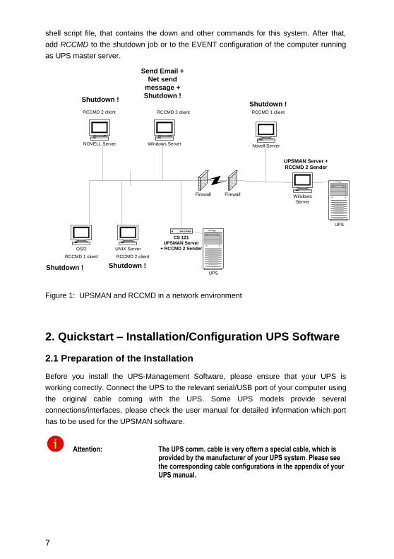
shell script file, that contains the down and other commands for this system. After that,
add RCCMD to the shutdown job or to the EVENT configuration of the computer running
as UPS master server.
NOVELL Server
UNIX Server
CS 121
UPSMAN Server
+ RCCMD 2 Sender
UPS
Windows Server
OS/2
Firewall Firewall
Novell Server
Windows
Server
UPS
RCCMD 2 client
RCCMD 1 client
RCCMD 2 client RCCMD 1 client
UPSMAN Server +
RCCMD 2 Sender
RCCMD 2 client
Shutdown ! Shutdown !
Shutdown !
Send Email +
Net send
message +
Shutdown !Shutdown !
Figure 1: UPSMAN and RCCMD in a network environment
2. Quickstart – Installation/Configuration UPS Software
2.1 Preparation of the Installation
Before you install the UPS-Management Software, please ensure that your UPS is
working correctly. Connect the UPS to the relevant serial/USB port of your computer using
the original cable coming with the UPS. Some UPS models provide several
connections/interfaces, please check the user manual for detailed information which port
has to be used for the UPSMAN software.
Attention: The UPS comm. cable is very oftern a special cable, which is provided by the manufacturer of your UPS system. Please see the corresponding cable configurations in the appendix of your UPS manual.

8
2.2 Windows 2000/XP/2003/VISTA/7/2008 UPSMAN Installation
General
The UPSMAN for Windows is a real background service and has no graphical output. The
UPSMAN is the only necessary process for all UPS management actions. The graphical
client modules (eg. Webinterface or UPSMON) are only for viewing the UPS data or for
for the graphical administration, but not compulsory for normal operation of a UPS
software like shutdown, messaging, etc.
Installation
The UPS-Management Software is distributed on a CD-ROM or as full version download
from the web site of the UPS manufacturer. A license key is required for both distributions.
The Windows part of the software is found in the root directory of the distribution package
and is started automatically or executing the “ INSTALL.EXE” command. This SETUP
process copies the desired UPS files to your local hard drive.
Licensing
The first input window is the license key of the CD (license = license key = key code). This
key code is shipped separately (as electronic document, paper document, or in any other
form – please contact your UPS dealer for information where to find the key code).
Every license key allows the customer to install one UPSMAN software (suite, consisting
of UPSMAN and several graphical client modules). To install RCCMD, another - separate
license key - is required – for every installation a new RCCMD key is needed – DO NOT
install the same license key more than once !
(The RCCMD sender functionality is already integrated into the UPSMAN. Only for the
client computers a new RCCMD license is required!) Additional RCCMD installations can
be executed from the same CD ROM or download image, using different license keys.
Beside copy protection, the license key distinguishes the different OEM UPS customers
from each other. It is not permitted to use any other license key than the one provided with
the software.
3. Start Installation + Basic configuration of UPSMAN
To start, please make sure that you have full administrator rights in order to complete the
installation.
Step 1: Put the CD into the CD-ROM drive of your
computer or download the software into a specific
directory on your computers harddisk.

9
Step 2: Please execute the installation program
install.exe in order to install the files to your
system and choose a desired setup language.
Step 3: Please enter your UPSMAN or RCCMD license
key to choose the correct software package. The
license key determines, which module can be
installed. The installation software shows a
progress bar until the software has been
extracted and the installation begins.
You can choose the language of your installation in the welcome screen. Choose your
language and click the “OK” button.
Figure 2: Introduction
In the next menue you can see the progress column where the next steps are visible. Click
the “NEXT” button to continue.

10
Figure 3: Enter your License Key
In the next menue you have to enter your license key – a picture shows an example. Enter
the license key an click the “NEXT” button to continue.
Attention: If you enter a wrong license number at this stage, the UPS-Management software will be set to a 30 day trial version. You may enter the correct license in the main window of the UPSMAN configuration at a later stage. (Please see figure below)
Figure 4: Thirty-Day Trial Version without Key Code

11
Figure 5: License Agreement
Read and confirm the license agreement and continue with the “NEXT” button.
In the next window enter the path where you want to install the software. Default is the
subdirectory “UPS” into the program files folder onto the hard disk “C:”.
Figure 6: Choose Install Folder
Click the « Next » button and choose the install set.

12
Figure 7: Choose Install Set
In the Install Set menu you can choose the following modules:
UPS MANAGER (UPSMAN) - This is a background process UPSMAN, the core of
the system. The UPSMAN is the service, which maintains the direct UPS RS-232/USB or
network connection with the computer and the UPS.
UPS Monitor (UPSMON) – This is the UPS Monitor Software. It is used to display a
graphical visualization of the data the UPS manager provides.
Graphical Charts (Gchart) – This is an ActiveX Control, which enables UPSMonitor to
display a graphical visualization of UPS values.
UPS VIEW Client – The webinterface of the UPS accessible through Webbrowser. It
shows the most important UPS data and alarms.
Help files are provided with the software, basicly it’s the user manual which you are
reading here and some extra informations which may be added from time to time.
In next menu you can choose to create a new program group (default) or to choose icons
elsewhere or not at all.

13
Figure 8: Choose Shortcut Folder
In the next menu you see an overview of your installation and you may now press
“INSTALL” to begin.
Figure 9: Pre-Installation Summary
Into the next window, you got the opportunity to open the required firewall ports 960 and
5769 automatically.

14
Figure 10: Firewall Configuration
The port 960 is used by the UPSMAN tray.
The UPSMAN tray provides the appearance of the UPSMAN message box as pop-up into
the foreground. If you do not want to receive messages from the UPSMAN, please close
the UPSMAN tray via the context menu. To disable the UPSMAN tray permanently, you
can disable it into the UPSMAN configuration.
The UPSMAN tray appears into the taskbar.
The red point means, that the UPSMAN service is not started or rather a problem has
occured (powerfailure, communication lost). Green means, that the UPS status is okay.
Figure 11: UPSMAN Tray
The USB support of your UPS depends on the hardware interface. In some cases (HID
compatible interface) – no additional driver is needed, since HID is already part of
Windows and Linux. In all other cases you receive a USB driver (eg. LibUSB driver) with
the UPSMAN software which is installed separately – or you receive a USB-2-serial driver
which creates a new virtual com port on your system. The difference between an USB and
an USB-2-serial driver is that using USB driver you use “USB” as communication port in
UPSMAN, and with USB-2-serial driver you use a COM port.

15
The installation of 3rd
party drivers will be through in some seconds - after this you may
receive a message to reboot your computer. This may be ignored if you have already a
USB driver from prolific on your system. In other cases please try first to communicate
with the UPS through UPSMAN and restart your system only if the communication or the
“search UPS” does not work at once.
NOTE: If a reboot is necessary, you can continue the configuration by clicking in the
Program group on “UPSMAN configuration” – the configuration will pop up and you can
continue the configuration – following the instruction on the next pages.
The main configuration page of UPSMAN is the DEVICE PAGE:
DEVICE PAGE:
Figure 12: UPSMAN Configuration
When the UPSMAN configuration starts up, choose from the UPS modellist your UPS type
– or use “Search UPS” to make UPSMAN try to identify your UPS type. If not clearly
identified, the UPSMAN will show you a list of UPS devices which are corresponding to
the search requests – please pick the right model from the list and confirm with OK.

16
During the auto search process this box will appear, you may stop the search at anytime
and choose the UPS from the drop-down list manually to speed up the process.
Figure 13: Select UPS Model
If the model “SNMP Adapter / RFC1628” is selected, please note that it is required that the
battery installation date is identical in the UPSMAN and CS121 configuration.
After having choosen the correct UPS type the UPSMAN standard installation is finished.
If you press now OK, the UPSMAN service will ask to start – press YES and if no further
error message appears within 1 minute, the UPSMAN will now watch the UPS and send
messages in case that an alarm occurs. If the UPS runs on battery and the battery have
only 3 minutes left, the UPSMAN will automatically shutdown this computer. In case of
alarms a messagebox will pop up similar to the one above and the user can connect with
UPS VIEW, UPSMON or any other graphical viewer to see the actual UPS alarms.
UPSMAN runs in windows as “service” -see windows service list how to stop/start the
upsman and related services.

17
Figure 14: Windows Services
Installation and basic configuration FINISHED. Your computer is now UPS protected
and will be shutdowned automatically in case of an extended Powerfailure.
For a simple UPS communication and automatic shutdown of the UPSMAN
computer – the configuration is complete!
For further UPSMAN configuration issues please continue to read in chapter 3.2 –
Advanced User – UPSMAN Windows configuration.
To check your configuration you may use one of the monitoring tools provided with your
UPSMAN software (UPS View, UPSMON, UNMS, JAVAMON or other). The moment you
can read UPS data from your monitoring interface, the installation was successful and you
may close the monitoring tool and keep the UPSMAN running in the background .
In the following figure is the UPS VIEW webinterface of a Protect 3.33 UPS. It shows the
most important UPS data and alarms. The “UPSMANHTTP” windows service running in
the background and provides the data for this webinterface. The following chapters explain
now the various UPSMAN monitoring tools, starting with most common UPS interface for
Windows “UPSMON”.

18
Figure 15: Protect 3.33 UPS Webinterface
3.1 Settings of the Authorization of the UPSMAN Service
This function is used for the commitment of the user authorization of the UPSMAN service,
which exceeds the system shutdown, e.g. execution of batch files, script files etc.
Open the menu of the properties window for the UPSMAN service (via control panel,
administration and services) and click the “Log On” button.
19
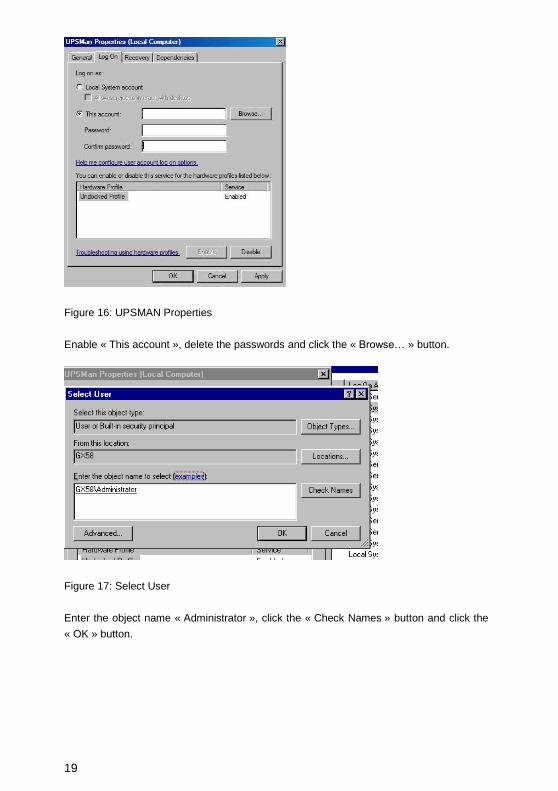
Figure 16: UPSMAN Properties
Enable « This account », delete the passwords and click the « Browse… » button.
Figure 17: Select User
Enter the object name « Administrator », click the « Check Names » button and click the
« OK » button.

20
Figure 18: UPSMAN Properties – This account
Enter the password for the Administrator, confirm it, click the « Apply » button and restart
the RCCMD service.
3.2 Silent Installation of the UPSMAN Installation
The UPS Management Software provides a silent installation, but it is required to enter
some settings into the “installer.properties” file. This file is located into the CD folder
\Upsman\Windows\OEM-ID (2 for AEG, 3 for Piller etc.).

21
Figure 19: Content of the „installer.properties“
It is required to remove the hash mark prior of the variable INSTALLER_UI=silent. In
addition the setting of the license key is required behind the variable GXLICENSEKEY=.
The UPS Management Software 5.8.04. or higher provides the parameter preselection
for the UPS communication. Remove the hash mark prior of the variable
UPSDEVICE=COM20:2400,e,8,1, and adjust the parameters accordingly.
3.3 UPSMON for Windows
UPSMON for windows is a graphical interface which is individually customized for every
UPS maker, for this a large variety of screens exists. Depending on the UPS makers
design and functions in the UPS the UPSMON appear more or less complex. In this
manual we desribe the basic functions which are part of any UPSMON version.
When UPSMON starts it will ask for a connection to a server. Enter the IP address or
hostname. To start a connection click on the button Connect.

22
NOTE: The UPSMON windows is a monitoring tool for any UPSMAN, unregarded on
which OS this UPSMAN is running. So you may use this tool to connect via an UPSMAN
server at UNIX, MAC or CS121.
To start a connection to different UPSMAN processes at the same IP address, enter the
port and the IP-address, or host name respectively separated by a comma (e. g.
5769,192.10.200.6). The port address can also be left out, if a single UPSMAN has been
started at the default port. The entry of the IP address (191.10.200.6) is enough. We
recommend using the TCP/IP protocol as a communication protocol.
Once connected with a server, the UPSMON responds with the main screen, allowing all
features to be operated.
After a connection has been established, the status main screen shows several windows.
The menu- and toolbar is at the top of the status chart. The bar contains the buttons
“Open A Connection”, “Close A Connection”, “Searching The LAN For Active UPSMAN
Services”, “Get Datalog As Text”, “Get Graphical Datalog”, “Open Scheduler”, “Change Of
Logdata Program”and “Open Remote Configuration”.
The Windows installation of UPSMON contains gChart, a graphical log file viewer.
.
Figure 20: UPSMON Statuspage of a Protect 3.33 UPS

23
The Windows UPSMON versions and the UPS VIEW Webinterface have an inbuilt
Scheduler interface to program actions on the remote UPSMAN. This Scheduler interface
is in both applications identical and allow to execute UPS tests or regular shutdowns on
certain days or time settings. Following a screenshot of the Scheduler in Windows, the
UNIX version is identical to this.
When connecting to your UPSMAN you can choose “SCHEDULER” . If you have
password on your UPSMAN configured, a password request will pop-up. After this you will
receive a scheduler screen, similar to the one we show below.
Figure 21: Scheduler in UPSMON, interface to program actions on your UPSMAN
The scheduler allows you to add new jobs which will be executed at the programmed time.
The UPSMAN logfile will show after the job has been executed about the results of the
programmed action. Generally the Scheduler shows the actual active job and the time or
date when it will be executed. Already executed actions are list and automatically removed
from the list if those jobs are expired or not longer recursing. By ADD Entry a new job is
created and added to the list. With DELETE Entry jobs may be removed from the list. With
EDIt entry you can change an already exisiting job. The other functions on the Scheduler
should be self-explanatory and do not require further explanation. Generally we
recommend NOT to program more batterytest jobs than once a month. Especially fulltests
may discharge your UPS batteries to a low level which may damage your batteries if this
is made too often. We recommend to do only short battery tests and replace the UPS

24
batteries in regular terms (interval depends on battery type). If you use BACS (Battery
Analyse and Care System) on your UPS batteries, you can see the actual status of the
batteries and decide when change is necessary. Without BACS we recommend to to this
on a regular basis.
Figure 22: UPSMON Statuspage of a Standard UPS without OEM Design
Since there are too many UPSMON screens we can not show those all in this manual.
UPS Functions
To execute tests of your UPS system choose UPS Functions from the menu Functions.
The results will be displayed in a table. The outcome of the tests depend on the settings of
the manufacturer. Selftest is a UPS hardware check. Battery Test is a short test of the
UPS working on battery. Custom Test switches the UPS on battery mode and will keep
discharging the batteries until the "downtime" has passed. With this command you may
check your batteries to see if they are still capable of supplying your system with the
"downtime" configured autonomy. Full UPS test is a deep discharge of the batteries and is
used for calibrating the battery. Tests should only be carried out if no user users are
active. Some tests may be deactivated depending if the UPS supports those features.

25
Note: Some OEM versions require the default password „cs121-snmp“, to get access to the UPS Functions.
Attention: When running a UPS Full test, please note not to interrupt the test, as long as it is active. If the test gets interrupted, the software will configure the autonomy time as the time-span of which the test has been running on the UPS before it has been interrupted. A test can be re-started after a 8 hour waiting period.
Note: A manual reset is possible by starting the upsman.bat.
Figure 23: UPSMON Device Command Window
UPS Extended Commands – Outlet switching
You can program the switching of the outlets or manually switch on or rather off the outlets
into the menu Extended Commands.
Note: Not every UPS supports this option.
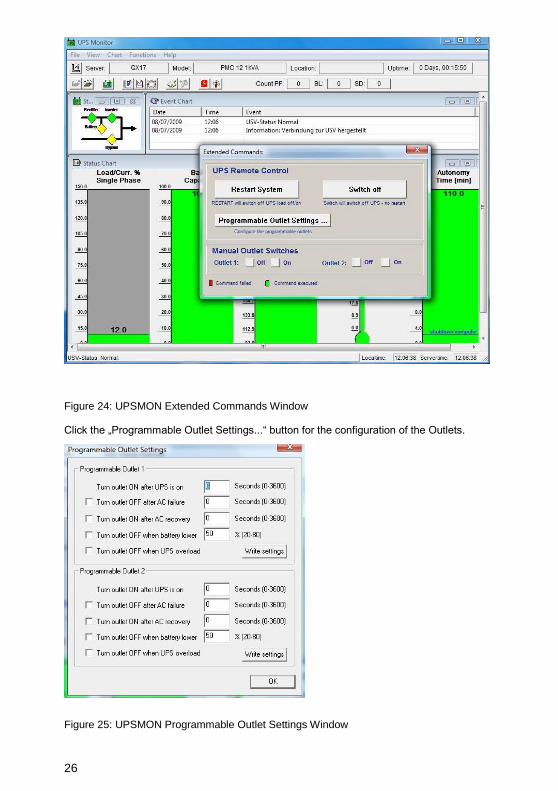
26
Figure 24: UPSMON Extended Commands Window
Click the „Programmable Outlet Settings...“ button for the configuration of the Outlets.
Figure 25: UPSMON Programmable Outlet Settings Window

27
The following configuration options are available for the outlets:
Turn Outlet ON after UPS is on – Delayed switching on of the outlets in seconds, after
the UPS was switched on.
Turn Outlet OFF after AC failure – Delayed switching off of the outlets in seconds during
a power failure.
Turn Outlet ON after AC recovery – Delayed switching on of the outlets in seconds after
a power failure.
Turn outlet OFF when battery lower – Definition of the switching off, if the battery
capacity is lower than x in percent.
Turn Outlet OFF when UPS overload – Switching off of the outlets during UPS overload.
Click the “Write settings” button, after you finished the configuration.
Voltage- and Frequence-Chart
Here the input voltage and frequency values of the last 24 hours (default) are displayed in
a bar or line chart/graphic. Depending on the UPS system (single or thriple-phased) one
measurement per phase is recorded.
In the menu File choose Get DataLog-File for Charts and wait for the measurements to be
transferred from UPSMAN to Upsmon. After the file transfer has been completed, you may
display the measurements of voltage and frequency via the menu Chart.
The menu Chart lets you choose between a chart showing minimum/maximum-results or
mean values.
The bar colours show whether the results have been outside the range of tolerance. The
accepted tolerance of the UPS-rectifier is displayed by a blue-line.
To monitor a certain part of the recorded time period, use the command Time Frame from
the menu Chart. After selecting a time period with the desired frame choose a voltage or
frequency chart again to display the measurements. It shows only the measurements
within this range (higher resolution of input data).
Textlog
In the menu File select Get TextLog-File and wait for the measurements to be transferred
from UPSMAN to Upsmon. The event-protocol includes all UPS events that have occurred
to date. A default UPS dump is printed if no errors have occurred. Only messages like
"Power fail", "Alarm", "Overload", "Battery low" etc. show a unusual situtation.

28
The UPSMAN log file can also be opened directly from the UPSMAN directory, please use
any standard text editor for this.
All other UPSMON functions which are not described in this manual come with a self-
explanatory description in the interface itself (“tooltips”). For further questions about those
functions, please contact your UPS reseller.
3.4 UPSVIEW for Windows
The Unix WEB SERVER offers the possibility to display all UPS data with a platform
independent WEB-Browser. In order to establish a connection from a WEB-Browser to a
UNIX WEB SERVER, please enter the IP address and a port number. Example:
http://192.168.202.91:8081. Port 8081 is used as a standard at the start up of the server.
Enter the following into a web-browser, if you want to get a remote connection to an UPS:
http://IP-address of the UPSMAN server:8081/cgi-bin/ups_view.exe?-ups_view
Figure 26: UPSView Remote Access
Via the « Log file » button, you can get the Data or rather Log files.

29
Figure 27: UPSView Log File
Via the menu « Functions », you can execute UPS tests.
Figure 28: UPSView Functions
To execute tests of your UPS system choose UPS Functions from the menu Functions.
The results will be displayed in a table. The outcome of the tests depend on the settings of
the manufacturer. Selftest is a UPS hardware check. Battery Test is a short test of the
UPS working on battery. Custom Test switches the UPS on battery mode and will keep
discharging the batteries until the "downtime" has passed. With this command you may
check your batteries to see if they are still capable of supplying your system with the
"downtime" configured autonomy. Full UPS test is a deep discharge of the batteries and is
used for calibrating the battery. Tests should only be carried out if no user users are
active. Some tests may be deactivated depending if the UPS supports those features.
Note: Some OEM versions require the default password „cs121-snmp“, to get access to the UPS Functions.

30
Attention: When running a UPS Full test, please note not to interrupt the test, as
long as it is active. If the test gets interrupted, the software will configure the autonomy
time as the time-span of which the test has been running on the UPS before it has been
interrupted. A test can be re-started after a 8 hour waiting period.
Via the menu „Scheduler“, you can schedule appointments for your UPS.
Figure 29: UPSView Scheduler
The scheduler allows you to add new jobs which will be executed at the programmed
time. The UPSMAN logfile will show after the job has been executed about the results of
the programmed action. Generally the Scheduler shows the actual active job and the time
or date when it will be executed. Already executed actions are list and automatically
removed from the list if those jobs are expired or not longer recursing. By Add Entry a new
job is created and added to the list. With Delete Entry jobs may be removed from the list.
With Edit Entry you can change an already exisiting job. The other functions on the
Scheduler should be self-explanatory and do not require further explanation. Generally we
recommend NOT to program more batterytest jobs than once a month. Especially fulltests
may discharge your UPS batteries to a low level which may damage your batteries if this
is made too often. We recommend to do only short battery tests and replace the UPS
batteries in regular terms (interval depends on battery type). If you use BACS (Battery
Analyse and Care System) on your UPS batteries, you can see the actual status of the
batteries and decide when change is necessary. Without BACS we recommend to to this
on a regular basis.

31
3.5 Advanced User – Windows UPSMAN Configuration
The following part of the user manual explains the advance user configuration items,
which are optional.
3.5.1 Advanced User - DEVICE Page
The configuration window is opened automatically and the user has to choose the correct
UPS model (manual startup of configuration : "UPSMAN –CONFIG). This is the most
important part of the configuration, because with the model name the correct UPS RS-
232/USB protocol is linked. If a wrong model is chosen from the list, the UPSMAN can not
start. If you would like to enter the configuration at a later point in time, you may do so by
logging on as administrator and click on “UPSMAN configuration” from the program group
UPS software. This icon is only available from the user account from which the installation
was performed in the first place (default). From other user accounts the configuration can
be started from the command line calling “upsman_config” in the UPSMAN folder.
Automatic start at server boot : The default of every UPSMAN is to start automatically at
every new server boot. If you want to change this, go to the control panel, services and
mark the UPSMAN Service under "Start". You can now change the start up now from
automatic to manual.
Selecting the UPS-Model: To select your UPS-model, click with the mouse on the scroll
box symbol on the right side of the model list. Next, choose the UPS model that you want
to install. All other adjustments which correspond with your selected UPS model will be
done automatically, if the UPS has serial or USB communication.
We recommend NOT to change the default settings of communication parameters of the
UPS – most UPS have a fixed baudrate which must not be changed.
UPS models with serial connections do not need additional adjustments, because these
models transfer all values to the UPS-Management software. If you have a UPS-model
with a port-type cable which does not transfer the connected Load to the UPS-Mana-
gement Software, you have to enter the values of the actual load manually. Add the input
power requirements in Watts of all connected units and calculate the Watt/0,8 (= VA).
ATTENTION: If you use a UPS-model with the port-type "cable", please notice that the values for Hold- and Recharge time are in accordance with the manufacturers specifications and should only be altered in special configurations since the UPS could be discharged before the system has been shutdowned.
“Power”, “Load”, “Hold Time”, “Recharge Time” are usually only for informative purposes,
but we strongly recommend to set these values properly, because UPSMAN uses these
configuration data whenever the UPS can not transmit such informations. We recommend

32
in any case to set the values for “Hold Time” and “Recharge Time” correctly, because the
user can not know, which UPS calculate the autonomy time out of these data.
Figure 30: UPSMAN Device Configuration
Power in VA – Nominal UPS voltage output in VA. Please do not change the
default value, unless you want to use the dry contacts communication.
Current UPS load in VA – Enter here the load currently supplied from your UPS
in VA. You can read this from the UPSMON, the webinterface or from the UPS
display. E.g.: If your UPS shows a load of 25% and has a nominal power of
1000 VA, enter here “250”.
Hold time – UPS autonomy time in minutes at 100% load. E.g.: If your UPS
provide, according to the manufacturer, at 100% load an autonomy time of 30
minutes, than enter here “30”.
Recharge time – Battery recharge time in hours. Please do never change the
default value, unless you get an advice from the manufacturer.
Date of Battery Installation – A warning for the battery durability will be reported
after 4 years (depend of type of the UPS).

33
Some UPS models have both port types (cable and serial). To guarantee the correct
function of your UPS-Management Software use the default settings and the cable
provided with the UPS or the software. Different cables will be required for different port
types.
Set battery health level in % - The UPSMAN version 5.8.00 or higher provides
an option for UPSs, which are not able to give a result after a battery test. The
default is 10%, that means, if the battery voltage got a difference of more than
10% PRIOR of the battery test, an error will be logged. Advice: Always execute
a battery test with load. Please use the nominal load, which will be present in
normal mode.
Location: Enter the name or place of your server or where the UPS in installed.
(e.g. ”Berlin”).
Port: Selecting the serial port/USB port
To select a serial port (COM port) click with the mouse on the COM check box on the right
side. The communication parameter will be set automatically, corresponding to the in step
1 selected UPS model. Normally these settings do not have to be changed by the user.
The COM ports are in most cases already installed and activated. See in the Control
Panel if the COM ports exist. The baud rate mentioned here is not important for the
UPSMAN, the UPSMAN has its own internal baud rate settings which match the UPS
manufacturer defaults.
OK button and Reset to factory settings.
When you click on the ”OK” button in the dialog window; the new configuration settings will
be stored in the registration database. The UPSMAN configuration will ask you, if you wish
to start the UPSMAN service now. If you like to return to the old, pre-set configuration
values and to start from scratch - please click the ”Restore factory settings” button. This
will execute in the background the file upsman.bat which resets your configuration and
returns with an empty configuration page.
3.5.2 Advanced User – Menu SYSTEM Page
Beside the UPS configuration page, more pages will appear if you click the “Advanced
User” button. All configuration data in the menus have "tool tips" in the corresponding
language. Every menu feature will be explained "online", following we start to describe the
SYSTEM page of UPSMAN:.

34
Figure 31: UPSMAN System Configuration
UPSMON Password: Default - no password - The user may enter here a
password, which will be requested whenever any UPSMON or other graphical
interface tries to connect.
UPS Check Rate (s): Defines the timing (in seconds) of the polling data from
the UPSMAN to the UPS. The system will be slowed down, if this value is too
small, because of continous communication with the UPS. If the value is too
high, the system will react more slowly in case of a power failure. For continous
use we recommend a value between 15 and 30 seconds.
UPSMAN/RCCMD2 Traps enabled: When this function is activated, UPS
events will be send in form of UPSMAN text message traps to RCCMD clients.
On the RCCMD client side, the two functions „Check UPSMAN alive“ and
„RCCMD2/UNMS traps“ have to be activated to receive such messages. When
a power failure occurs e.g. a message box is displayed on the RCCMD client.

35
Figure 32: Message on RCCMD client when UPSMAN trap has been received
Enable network broadcast for events: This enables the NET SEND broadcast
(MS Messenger Service has to be enabled) with alarm messages to the
network. If the messenger service is not running, a local message will pop up
automatically.
Use SSL as default for all RCCMD events: This will activate that all RCCMD
(Remote Console Commands to client computers) events will use SSL (Secure
Socket Layer) encryption. This requires that ALL your RCCMD clients use SSL
as well !
Enable Local System Shutdown: Defines if the system will start the shutdown
routine in the event of a shutdown call from the UPS during a power failure. If
you disable this function, no shutdown will be performed ! In the case of a
shutdown, the internal event routine will close down all active applications. The
shutdown of the UPSMAN computers is following the sript in the file
shutdown.bat (in unix : shutdown.sh) from where the shutdown programs (in
windows “exitwin.exe” and other commands will be started.
ATTENTION: Make sure that the check box "System Shutdown enabled" is always active if you have additionally the “UPS Shutdown” fuction active ! Otherwise the UPS might be turned off during a power failure before the system has been shutdown properly.
Down time: Defines how many minutes before the UPS battery is discharged,
that the shutdown procedure begins. This timing has to be large enough to
guarantee a proper shutdown of the system before the UPS is turned off.
Ensure that this value is calculated on a large scale: (e.g. with 10 minutes hold
time of the UPS, start the shutdown procedure at least 3 minutes (default)
before the batteries are empty (battery low).

36
Enable UPS Shutdown: (Default = on) When OFF, the UPSMAN computer will
not execute the shutdown file.
Initiate shutdown always after x minutes: This enables/disables the
execution of the shutdown after a period of time wherein the UPS is working on
batteries.
Configure shutdown: The type and sequence of a shutdown can be selected
and edited here. Please note, that the UPS can not boot the computer after
power returned, when POWEROFF is active (ATX boards). Default is shutdown
windows “Exit – shutdown”. In the shutdown-configuration users can add self-
defined actions to the shutdown sequence via the “Add custom application”
button. In addition users can determine the shutdown sequence order.
ATTENTION: Be sure to use the “start” initiative for using EXE programs within batch files (i.e. “start notepade.exe). Also use the “call” initiative for using other batch files within batch files (i.e. “call mybatch.bat”).
Figure 33: Windows UPSMAN Shutdown Sequence Configuration
Enable UPS shutdown: Defines if the UPS will be turned off after the
completion of the shutdown procedure of the server.The UPS shutdown section
is not supported by all UPS manufacturers. In particular, devices with the
connection-type cable do not support a schedule-controlled shutdown and
restore function.
UPS Down Delay (s): Defines how many seconds after beginning the shutdown
procedure (see Down time) the UPS will turn off.

37
UPS Restore Delay (s): Defines how many seconds after turning off the UPS
the system is turned on again. For most UPS types it is necessary, that the
power has been restored before the UPS has completely switched off. With
some UPS devices the entry "0" disables an automatic restart and the UPS
needs to be switched on manually.
Enable SNMP Support: Enables or disables the SNMP support. Please check
in the event log, if this function is properly started. A message "SNMP
communication could not be started" shows, that an error occurs. No message
means, that this function is working. To install SNMP service add this software
function via Microsoft additional software installation.
Restart SNMP Service: This will activate a stop/start of the SNMP service
under Windows. This function avoids start problems of the UPSMAN agents,
using older or not maintained systems.
Audible Settings: You can define the audible settings of the UPSMAN
message box:
- Beep off
- Beep endless
- Beep (1 to 9 times)

38
3.5.3 Advanced User – Menu FILES Page
Figure 34: UPSMAN Files Configuration
Attach log files to Mail-Events: Enable this function, if you want to attach the
“upslog.csv” and the “UpsData.csv” at all emails that will be send by the UPSMAN.
Event Logfile Filename: “upslog.csv” is the name of the event/alarm text
protocol. The default is a MS-Excel compatible CSV file format. “Status Dump”
writes regularly (approx. every 10 minutes) the current UPS status into the text
log file.
Data Log File: “upsdata.csv” – This file contains the logged measurement
values of the UPSMAN, like voltages and currents.
Logfile max. Size (kb): Defines the size of the log files in KB.
Write raw data to file: Enable this function for logging of the RS232/USB
communication between the UPS device and your computer to a file called
“line.raw” into the UPSMAN folder. This features will be used for the analysis by
the UPSMAN support team.
39
Attention: This file can be very huge in a short time, especially at
USB communications. We recommend to enable this
function for the analysis only.
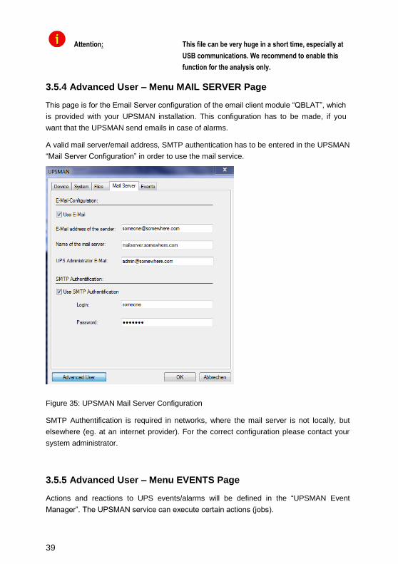
3.5.4 Advanced User – Menu MAIL SERVER Page
This page is for the Email Server configuration of the email client module “QBLAT”, which
is provided with your UPSMAN installation. This configuration has to be made, if you
want that the UPSMAN send emails in case of alarms.
A valid mail server/email address, SMTP authentication has to be entered in the UPSMAN
“Mail Server Configuration” in order to use the mail service.
Figure 35: UPSMAN Mail Server Configuration
SMTP Authentification is required in networks, where the mail server is not locally, but
elsewhere (eg. at an internet provider). For the correct configuration please contact your
system administrator.
3.5.5 Advanced User – Menu EVENTS Page
Actions and reactions to UPS events/alarms will be defined in the “UPSMAN Event
Manager”. The UPSMAN service can execute certain actions (jobs).

40
NOTE: Although the jobs in the joblist of the EVENT manager are executed top-down – but since every job has its own timer (eg. delayed, immediately, etc.), the priority of the jobs depend on the individual timers, not on the rank in the job list. If you want to change the rank of a job, you can drag & drop the job in this list, but still the individual timer remains unchanged.
Which events are configurable depends on the type of UPS. Every UPS contain individual
alarms, large UPS have usually more alarms than smaller UPS. The following section
explains the pre-settings of such an event list on the example of a 1 phase UPS.
Figure 36: UPSMAN Event Config.
The event overview displays all available
events of this type of UPS and the user
configuration of the corresponding actions.
Every “X” means that this event has at
least 1 job as executable listed. With a
double mouse click the user may open the
event to see, which jobs are already
configured. Now the user may add extra
jobs or actions to this event. The most
important event is “Powerfail” – here the
user has to configure which RCCMD
clients are to be triggered in case of
alarms. In addition it is possible to define
„Threshold Events“ for the variables
„Battery Voltage“, Seconds On Battery“,
Battery Autonomy“, Battery Charge, UPS
Temperature“, „Input Voltage“ and „Output
Load“. Please also check the following
chapters of the manual.

41
Figure 37: Advanced Buttons
In order to configure the event, click on the
designated event and the “Event Jobs” list
opens. For every event there are pre-
settings, most of them are log file entries
and RCCMD messages as traps. In the
example there are three jobs configured for
the event „Powerfail” - 2 jobs will send out
standard text messages, (can be edited in
the "Message.dat" file), whereas the 3rd
event writes a message into the log-file. In
order to add a job, please click the “Insert”
button and the following functions page
opens.
The “Reset” buttons below are to reset the
alarm counters of UPSMAN, visible in the
UPSMON or other graphical viewers
(statistical information since the software
has started).
Figure 38: Insert Functions
Choose the desired function and set a
timer and define, when and how often this
function should be executed. Any event
that contains a delay will be executed
ONLY, if the alarm is still valid when the
timer has run out. E.g. if you configure to
send an RCCMD shutdown after 30 sec. –
this job will be executed ONLY, if the
powerfail is still the case after the 30 sec.
have run out. If the power has returned at
29 sec. – nothing will happen.
The following functions are available in most UPS :
Send a Shutdown UPS
Signal
Switches the UPS output off after a pre-set time.
Please make sure that the UPS is not being
switched off before a system shutdown is
executed, as otherwise important data may get
lost.
42
This shutdown signal only executes the output
switch off - but NOT the shutdown of connected
computers! If you define such an action, make
sure that RCCMD is triggered before! The user
can configure a delay (in seconds) before the
switch off is executed.
Send Message box with text Sends a network message using “net send”. The
Windows Messenger Service has to be active to
use this function. Enter a user or a machine
name or use the "*" character in order to send
the message to all users. If you want to add
several addresses, please part them with
semicolon and a blank.
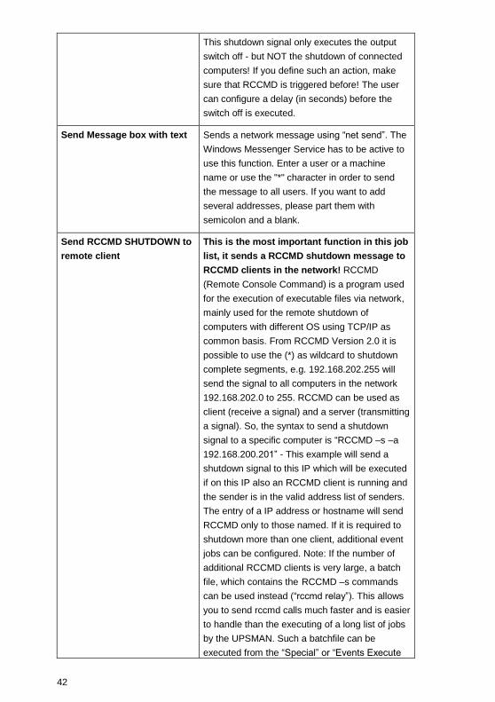
Send RCCMD SHUTDOWN to
remote client
This is the most important function in this job
list, it sends a RCCMD shutdown message to
RCCMD clients in the network! RCCMD
(Remote Console Command) is a program used
for the execution of executable files via network,
mainly used for the remote shutdown of
computers with different OS using TCP/IP as
common basis. From RCCMD Version 2.0 it is
possible to use the (*) as wildcard to shutdown
complete segments, e.g. 192.168.202.255 will
send the signal to all computers in the network
192.168.202.0 to 255. RCCMD can be used as
client (receive a signal) and a server (transmitting
a signal). So, the syntax to send a shutdown
signal to a specific computer is “RCCMD –s –a
192.168.200.201” - This example will send a
shutdown signal to this IP which will be executed
if on this IP also an RCCMD client is running and
the sender is in the valid address list of senders.
The entry of a IP address or hostname will send
RCCMD only to those named. If it is required to
shutdown more than one client, additional event
jobs can be configured. Note: If the number of
additional RCCMD clients is very large, a batch
file, which contains the RCCMD –s commands
can be used instead (“rccmd relay”). This allows
you to send rccmd calls much faster and is easier
to handle than the executing of a long list of jobs
by the UPSMAN. Such a batchfile can be
executed from the “Special” or “Events Execute

43
Program” functions.
Please note that RCCMD shutdown calls should
always be configured in the “UPS Battery low”
without any further delay.
Send email
Sends an individual email text at this event.
Enter an email address and the corresponding
text into the field. Please note that you need a
configured SMTP server on the UPSMAN
computer. “Qblat” is the email program which is
triggered by UPSMAN email configuration.
Send RCCMD EXECUTE to
remote client
This action initiates the execute.bat on a defined
RCCMD remote client (IP-address). Through this
function the UPSMAN can execute any
command on the remote computer if the correct
path and name of the program is known on this
remote computer with RCCMD running.
Send RCCMD MESSAGE ID
to remote client
In this menu the user can send an ID from the
messages.dat to other users. These IDs are pre-
defined text messages. Open the file
message.dat to see the default text of such
messages. Text entries can be altered with an
editor. The edited text is then given out in a
textbox at the remote client. This is useful if you
want to send a messagebox from Windows
UPSMAN to a UNIX system - the problem of
sending messages to different operating systems
can be solved through this.
Start Alarm Beeper with
messagebox
This function displays a message box with an
audible warning on the screen of the UPSMAN
computer.
Send RCCMD MAIL ID to
remote client
Similar to RCCMD message ID, a message ID is
send, which is then forwarded from the RCCMD
client as an email to the corresponding receivers.
This is useful if the UPSMAN computer for any
reason can not send emails directly, than the
remote client can do this job. The user can pick
on of the default text messages as ID no. from
the file message.dat or us RCCMD MAIL TXT
instead to create its own text.
Send RCCMD MAIL TXT to Like the send RCCMD mail function, an email is

44
remote client send from the RCCMD client as relay. The user
may enter here any individual text.
Send RCCMD LOG TXT / LOG
ID to remote client
This writes a log file text (customized or as
predefined text if you use ID) into the RCCMD
remote clients log file. This maybe useful if a
common log file is wanted, where all UPSMAN
computers write into. This log file maybe on any
network computer with RCCMD.
Send RCCMD MESSAGE (ID
or TEXT) to remote client
The user can configure a text message
(customized or as predefined text if you use ID)
which is transferred to the RCCMD client and
pops up as text box. This is useful if you want to
send a messagebox from Windows UPSMAN to
a UNIX system - the problem of sending
messages to different operating systems can be
solved through this.
Execute Program
Executes a configured program on this
computer. Please enter the full path to the
executable file on the UPSMAN computer. It is
recommended that the executable file is located
in the UPSMAN folder or in any other folder
where a path is set to.
Write to Log file
UPSLOG.CSV
Writes any text into the upslog.csv text file on
this UPSMAN computer.
Send default messages IDs
from file messages.dat
Sends pre-set network messages, using the
receiver name and message ID. This standard
message can be configured in the
"message.dat". Open the file with an editor in
order to change or check the text of the
corresponding message ID.
Write to MS Event Viewer When an alarm occurs, this function write to the
MS EVENT LOG called also “Event Viewer”. The
user can now alter the Windows standard event
viewer entries by choosing the type
(informational, warning and error) and by adding
text to the event viewer entries.
In the “Event Viewer” you will find the UPSMAN
events as :
Information 8 Upsman Stopped

45
Information 7 Upsman Started
For further text entries use this function and add
your text and severity.
Send RCCMD trap message
by ID
This function enables UPSMAN to send
RCCMD2/UNMS traps, which shows the UPS
status as a text message on the remote client. If
activated it will display a local message box on
the client whenever the UPS status changes.
Please also note that the “RCCMD2/UNMS trap
enabled“ box is activated at the RCCMD client
to receive the trap messages.
Send RCCMD trap message Identical to RCCMD trap messags by ID, but the
user may define his own text.
3.6 Avanced User – Special Tools and Configuration Advices
3.6.1 Advanced User - UPSMAN Debug and Line.raw Tools
After the installation the files are found in (default) c:\program files\ups\. Directory. Here
the files of the UPSMAN and UPSMON, other optional components have subdirectories.
UPSMAN DEBUG: Usually UPSMAN windows starts as service in the background. If you
want to start UPSMAN as application in the foreground to create tracefiles, than open a
command line, stop any upsman service and enter ”upsman –debug“. Thereby the
UPSMAN service will display support information at the command line. This information
may be requested from the UPS support service if you encounter communication
problems with your UPS.
3.6.2 Email to SMS
In order to send a SMS message in case of an alarm, you have to use the “Email to SMS
Service” of your GSM provider. This is a service where the UPSMAN sends an email to
the service center of your GSM provider, who converts the email into an SMS. This
service is standard in most GSM networks and very reliable compared to modem
solutions. For receiving emails as SMS you have to contact your GSM provider to open
this service. In the following we describe how this works with some GSM providers in
Europe, since these providers change this very often, please refer to the website of your
GSM provider to find out how “Email to SMS” can be activated for your cell phone.
Example:
GSM Provider T-Systems D1

46
Your D1 email address will be [email protected] (e.g.:[email protected])
Please note that you enable receiving emails on your cell phone. This is done by sending
a SMS with the message “OPEN”, to the number 8000.
Only the subject or the text field of the email will be transferred as a SMS, 160 characters
from the subject and text field.
Important: If you want to stop receiving emails, please send a SMS to the number 8000,
with the text “CLOSE”.
(If you want to enable the email transfer again, just send a message to the number 8000,
containing the text “OPEN”, as described before.)
GSM Provider Vodafone
In germany the vodafone email-to-SMS server is called „vodafone-sms.de“. Please take a
look onto the vodafone website of your country for the accordant server name.
Please note that you enable receiving emails on your cell phone. This is done by sending
a SMS with the message “OPEN”, to the number 3400.
Only the subject or the text field of the email will be transferred as a SMS, 160 characters
from the subject and text field.
Important: If you want to stop receiving emails, please send a SMS to the number 3400,
with the text “CLOSE”.
(If you want to enable the email transfer again, just send a message to the number 3400,
containing the text “OPEN”, as described before.)
Other providers
Please ask your cell phone network provider for informations about the email to SMS
settings.
3.6.3 Save & Load Configurations
The number of available events and jobs depend on the type of the UPS. Although each
event and job may differ from UPS to UPS, the general configuration process for each job
is the same as follows. Your configured event files can be saved and loaded for backup
purposes or for simply having alternative configurations available.

47
Figure 39: Load/Save Jobs
Your configuration for this UPS model will be saved into a file. If you later want to use this
configuration again, please make sure that the UPS type has NOT changed! Only event
files which have been recorded previously will work when reloaded, if the UPS type has
not changed.
3.6.4 Examples - Execute Program with Parameters
The following shows some examples for customized configurations of UPSMAN.
Example: How to create a load statistic via UPS EVENTS on Windows:
The log file datalog.csv constantly creates the current MS-Excel compatible log file with all
important UPS data and can also be extended or adjusted via the messages.dat ID 700
file (single-phased UPS) or messages.dat ID 800 (three-phased UPS). In the following
example, we show how the EVENT manager can be used to create a “load” statistic:
48
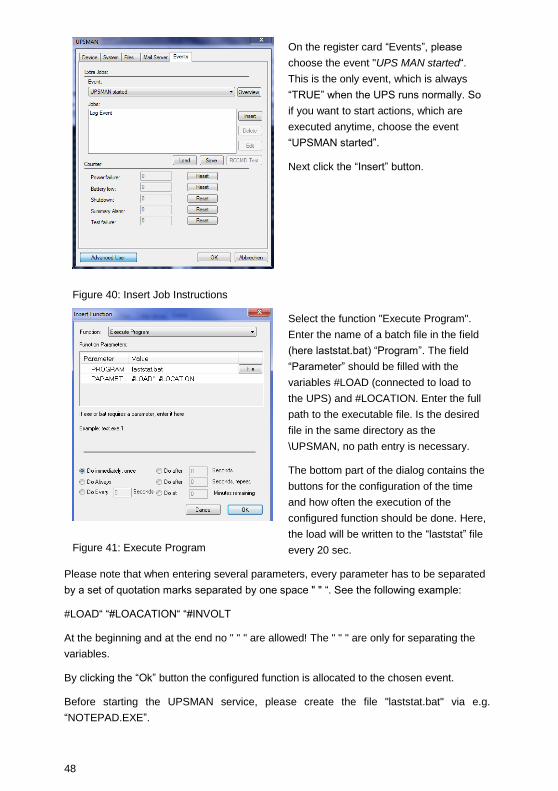
Figure 40: Insert Job Instructions
On the register card “Events”, please
choose the event "UPS MAN started“.
This is the only event, which is always
“TRUE” when the UPS runs normally. So
if you want to start actions, which are
executed anytime, choose the event
“UPSMAN started”.
Next click the “Insert” button.
Figure 41: Execute Program
Select the function "Execute Program".
Enter the name of a batch file in the field
(here laststat.bat) “Program”. The field
“Parameter” should be filled with the
variables #LOAD (connected to load to
the UPS) and #LOCATION. Enter the full
path to the executable file. Is the desired
file in the same directory as the
\UPSMAN, no path entry is necessary.
The bottom part of the dialog contains the
buttons for the configuration of the time
and how often the execution of the
configured function should be done. Here,
the load will be written to the “laststat” file
every 20 sec.
Please note that when entering several parameters, every parameter has to be separated
by a set of quotation marks separated by one space " " “. See the following example:
#LOAD“ “#LOACATION“ “#INVOLT
At the beginning and at the end no " " " are allowed! The " " " are only for separating the
variables.
By clicking the “Ok” button the configured function is allocated to the chosen event.
Before starting the UPSMAN service, please create the file "laststat.bat" via e.g.
“NOTEPAD.EXE”.

49
The content of this example file may look like the following:
Figure 42: Laststat File using a Text Editor
Start the Upsman service. If you have followed the above example, now every 20 seconds
the file "Load statistics.txt”, containing the current values of the UPS load, is created and
updated.

50
3.6.5 Examples - Send Email Function
Figure 43: Send Email Configuration
The send email job can send
individual emails to single
receivers or receiver groups.
These users or groups may be
defined in either the UPSMAN
address book (for groups) or in
the MS Outlook address book.
Click the “Upsman
Addressbook” button and create
a new group. Enter a list of
email addresses in this group,
which will receive the text
message for this event, if an
alarm occurs.
Figure 44: UPSMAN Address Book
The UPSMAN address book
makes it easy to organize
recipients into groups. The read
and write function allow the user
to make back ups of this UPS
group address book.

51
3.6.6 Examples - RCCMD Mail ID
Figure 45: RCCMD Email Example
With this function an email will be send
from the RCCMD client as relay. Instead of
an individual text, a pre-defined message
ID will be send. Enter the IP address or
hostname of the RCCMD client, which you
want to relay this email. Enter the port
parameter into the field “PORT”. The
standard port is 6003 for receiving RCCMD
signals. The message ID can be selected
by clicking the “Browse” button (see next
figure). This function may be useful, if the
UPSMAN computer is not able to send
emails directly. Using an RCCMD client as
relay solves this problem.
Figure 46: Message ID Example
Using an editor you can modify message
IDs in the default messages.dat file.

52
3.6.7 Examples - Send RCCMD execute to remote client
Figure 47: RCCMD Execute Example
This action initiates the execution of a
batchfile “execute.bat” on a defined remote
RCCMD client (IP-address). This bat file is
configured to start programs on the remote
machine.
In this example the “execute.bat file” will be
executed at remote client (IP address
192.168.202.156), at port 6003. The entry
made in the parameter field will be sent
from UPSMAN as a parameter to
execute.bat and in this way “my-
program.exe” is started.
3.6.8 Examples – RCCMD with SSL via UPSMAN
The Secure Sockets Layer (SSL) protocol is a cryptographic protocol that provides
security and data integrity for communications over TCP/IP networks.
Open the UPSMAN configuration. Click the “Advanced User” button on the lower left side,
then the tab “System” and enable the “Use SSL as default for all RCCMD events” box.
Figure 48: SSL Main Activation

53
The SSL network feature requires correct time settings, so it is required to configure a
correct time at the work station, where the UPSMAN software is installed.
It is required to enable SSL for each RCCMD event function. Click the tab „Events“. Click
on the desired event, to add an accordant function. Click the „Insert“ button and select the
desired RCCMD function. Enable the SSL box to activate the SSL feature.
Figure 49: SSL Activation of a single function
Close the configuration windows with the “Ok” button and restart the UPSMAN service.
Start the RCCMD Wizard installation and enable the SSL network feature.
Figure 50: SSL Configuration

54
Figure 51: Advanced Network Settings
3.6.9 Examples - RCCMD with own SSL certificates
In this chapter we will describe, how to use an own SSL certificate with RCCMD, e. g.
OpenSSL ( http://www.openssl.org ):
Be your own CA
Using OpenSSL it is quite simple to become your own CA. Just run:
CA.pl –newca
Done! Just ensure, that you select a useful CN (common name)!
Create your RCCMD certificate
You need to create your certificate for RCCMD now. As it will use it for verification, it
should contain the same useful common name (CN), that you selected for the CA. The
private key must not be encrypted to let the RCCMD Client (service) start without trouble.
Therefore we use the “–nodes” option and the “-newreq” command:
CA.pl –newreq -nodes
Sign with your CA:
CA.pl –sign
Now create an empty file named “rccmd.pem“ and copy the cert information of
newcert.pem (rccmd certificate), newkey.pem (private key) and cacert.pem (CA) into it.
Please note, that the exact copying is required to use it without trouble!
Use your own RCCMD certificate
Do the following steps at the RCCMD Client and every sender (UPSMAN default directory:
C:\Programs\UPS\Upsman):
Backup the existing “rccmd.pem”
Replace the existing “rccmd.pem” with your own

55
Restart the RCCMD Client
Restart the RCCMD Sender
3.6.10 Examples - WOL – Wake On LAN
Figure 52: Wake-On-LAN Signal
This function will wake up hibernating
or sleeping computers to go back
online. The receiving computers of this
signal must have network cards, and
operating systems that support this
function (“magic packet”). The MAC
address can be determined in dos
consoles by entering the command:
“ipconfig /all” at the DOS prompt. Here
you can find your network card MAC
address. To wake up this computer,
enter the MAC address in this
UPSMAN job. A password is not
needed unless you have a BIOS where
you can define such a password for
WOL magic packets.
3.6.11 Examples - Scripting
The transfer of internal variables of the UPSMAN to self-created batch files is possible
with the UPS-Management software. The normal batch file programming is used for this.
In the batch file the values can be selected with %1, %2 etc. as usual. The definition is
created directly in the JOB.
Example l:
”net send GX9 UPS autonomy time #AUTONOMTIME”
This entry in the JOB sends a network message to GX9 with the information on
#AUTONOMTIME, which is transferred directly from the UPSMAN.
Example 2:
”net send GX9 autonomy time #AUTONOMTIME minutes Battery Capacity #BATTCAP
%”

56
This entry in the JOB sends a network message to GX9 with the information on UPS
Autonomy time and battery capacity, which are transferred directly from the UPSMAN.
The receiver GX9 gets this: ”message from GX 0 to GX 9”: ”Autonomy Time 46 minutes
battery capacity 85.000 %”
Example 3:
JOB Power fail: c:\ups\mybatch.bat #AUTONOMTIME #INVOLT #OUTPOWER
This entry defines #AUTONOMYTIME as ”%1”, #INVOLT as ”%2”, #OUTPOWER as ”%3”
etc.. In the batch file itself, the following can be configured:
Mybatch.bat
Net send * ”Power fail at UPS detected!!”
Net send <USER> ”Power fail! Inputvoltage %2 Volt, only %1 minutes left!”
Every UPSMAN provides at least the following variables
Variable Function
#OUTPOWER Actual load in % at the UPS
#OUTPOWER Actual load in % at the UPS
#TEMPDEG Actual UPS temperature in Celsius
#AUTONOMTIME Actual autonomy time in minutes
#LASTTSTBUPT Last tested BACKUPTIME (UPS test) in minutes
#STATUS Actual UPS Status in minutes
#LASTERR Last error
#TIMEUNTILSHTDWN Actual Remaining time (remaining battery time until SD)
#RUNTIME Actual Remaining time (remaining battery time until SD)
#INCURR Voltage input power
#BATTVOLT Battery load in Volt (V)
#INFREQ Input frequency in Hz
#OUTFREQ Output frequency in Hz
#CNT_PF Counter for power failure
#CNT_BL Counter for battery low

57
#CNT_SD Counter for shutdown
#CNT_SA Counter for summary alarms
#CNT_TF Counter for test errors
#INVOLT Current Input voltage in Volt (V)
For the special UPS integration into the UPSMAN software, more variables can be
provided. Please ask your UPS dealer/manufacturer for more information on additional
variables.
3.6.12 Start Options of the UPSMAN Module
Upsman.exe is a Windows service application. The configuration parameters are read
from the Windows registration database. By default the UPSMAN service is set to start
“automatic” – In the following we describe options to start and configure UPSMAN service.
Please start the upsman.exe via the control panel with the help of the service icon.
Alternatively start the UPSMAN with a command line: net start upsman. To use the
UPSMON (graphical interface), please install the TCP/IP protocol on your system.
Upsman.exe can also be started from the command line as foreground process. The
following parameters are supported:
-install installs the UPSMAN as a service
-remove uninstalls the UPSMAN service
-config starts the configuration program
-libver shows the version release of the UPSMAN
-debug starts the UPSMAN as foreground process (not as service)
and displays a window for error function analysis. In addition a “line.raw” file is
created, which logs the entire communication between COM port and end
device. The file can be decoded by our service team in order to track down
errors.
In order to allow an automatic start of the UPSMAN module at server boot; please set the
service start-up status in the control panel to automatic.
In case the service needs to be removed or deactivated, please change the start-up status
in the control panel section SERVICES to manual. In case an automatic start under
Windows is not desired, please enter the command line: Upsman -remove or deactivate
via the corresponding icon "UPSMAN Remove".

58
In order to reinstall the service after removing it, please change to the UPSMAN directory
and enter the command line: "UPSMAN.BAT". This is a “reset” command where UPSMAN
service is now reinstalled and the configuration program will start.
The local UPSMAN directory contains “send.bat”, log file entries, “messages.dat”, which
are part of the event configuration, where the file is existing. Using an editor all of these
files can edited and modified. The event configuration however enables a complete
configuration of these files.
Stop the USV-Management Software
In order to stop the UPSMAN service, a command line with the command: net stop
Upsman can be entered. Also, the control panels (services) in the Windows UPSMAN
Icon in the status panel can be used.
3.6.13 UPSMON for the command line
The Upsmon for Windows is a command line programm which can be used in batch
programs. All UPS values can be displayed and used for programming of batch files and
scripts for the processing UPS information further. Also, the Upsmon activates all UPS
functions and UPS tests. Because of this, UPS commands can be transferred from other
applications to the UPSMAN. This interface allows the access to every UPSMAN in the
TCP/IP network and the control of all connected UPS devices.
Parameter for the Upsmon
usage: upsmon <hostname or IP adress> <-vicdtrh>
-v Program information
-i <value> Query of a UPS-measurement
-c <ups command> Execution of a UPS-function
-d <ups command with duration> <seconds> Execution of a timed UPS-function
-t <ups test> Execution of a UPS-test function
-r <ups test> <values> Query of a UPS-test function result
status (4= OK)
inputvolt
battvolt
temperature (in celsius)
autonomietime (in minutes)
59
autotime (in minutes)
battcap (in %)
batterycapacity (in %)
outputpower (in %)
inputfrequenz (in Hz)
outputfrequenz (in Hz)
<ups command>
testbatt
batterytest
fulltest
canceltestbatt
cancelbatterytest
cancelshutdown
alarmreset (Buzzer off)
<ups command with duration>
shutdown
restore
<ups test>
customtest
batterytest
selftest
fulltest
shutdownrestore down seconds restore seconds
Please note that the answer depends on the typ of protocol of the UPS. Returns with "0"
means that the values are available for this UPS model.
Example: Command for the Shutdown UPS and Restore:
./upsmon –d shutdownrestore 90 120
Note that UPS is controlled directly, a system shutdown is not initiated using the command
"upsmon –t shutdownrestore [x] [x]“ The system needs to initiate its own shutdown routine

60
after such a command. Please use the corresponding shutcmd.exe program, as in this
example:
; Shutdown Batch for NT:
;
./upsmon <servername> -t shutdownrestore 60 90
./shutcmd.exe /L /Y /C /T:05 "Local shutdown now!"
Installation:
The program UPSMON.EXE requires a successfull installation of the UPSMAN in the
network.
Please copy the program with the Dlls MSVCRT.DLL and MSVBD60.DLL into a directory
on your Windows computer. As soon as the UPSMAN is active via the TCP/IP connection,
the program is ready for use.
The use of the UPSMON API with own software is possible, please contact your
software support or the Generex directly.
3.6.14 UPS Management Software for WIN 2008 Server Core x64
The installation/configuration of the UPS Management Software on a Windows 2008 Core
x64 system got some specifics. The default folder is:
C:\Program Files (x86)\UPS
Figure 53: Installation Folder

61
Please take a look into chapter 3 on page 7 for further information of the installation
procedure and the basic configuration.
The UPSMonitor will be started out of the following folder :
C:\Program Files (x86)\UPS\upsmon
Figure 54: UPSMON Folder
Execute the « upsmon32.exe » to start the UPSMonitor.
The UPSView enables the remote access to the UPS data via web-browser. To be able to
use the UPSView, it is required to open the firewall port 8081 as follows :
netsh firewall add portopening tcp 8081 "upsviewport“
Enter the following into your web-browser :
http://IP-AddressCore:8081/
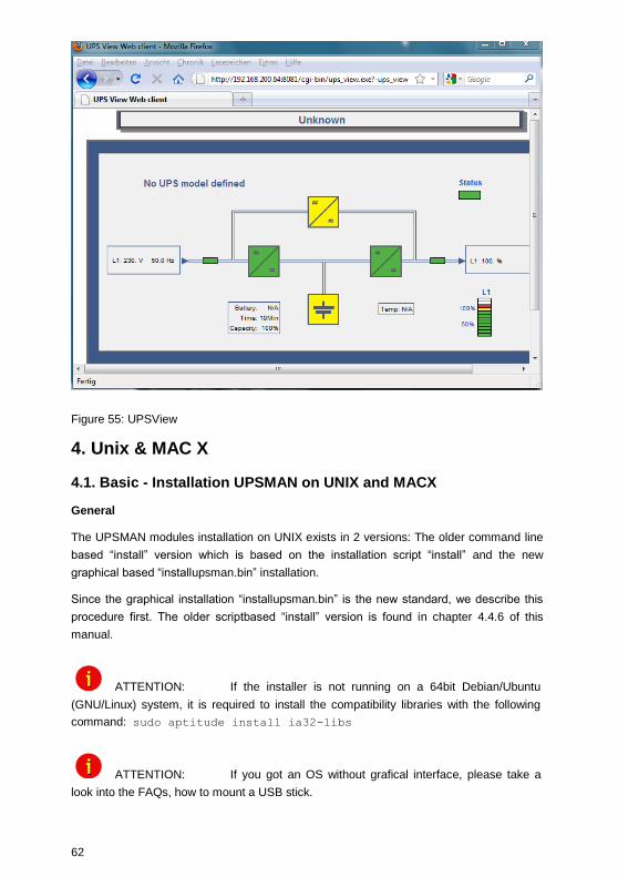
62
Figure 55: UPSView
4. Unix & MAC X
4.1. Basic - Installation UPSMAN on UNIX and MACX
General
The UPSMAN modules installation on UNIX exists in 2 versions: The older command line
based “install” version which is based on the installation script “install” and the new
graphical based “installupsman.bin” installation.
Since the graphical installation “installupsman.bin” is the new standard, we describe this
procedure first. The older scriptbased “install” version is found in chapter 4.4.6 of this
manual.
ATTENTION: If the installer is not running on a 64bit Debian/Ubuntu
(GNU/Linux) system, it is required to install the compatibility libraries with the following
command: sudo aptitude install ia32-libs
ATTENTION: If you got an OS without grafical interface, please take a
look into the FAQs, how to mount a USB stick.

63
INSTALLATION via CD
Open your CD-ROM folder and click the „start.html“ (HTML file, starts a web-browser)
button. Enter your license key (see below, where to find it).
Figure 56: CD-ROM Folder
Click into the download menu the « UPSMAN Suite » button and select the accordant
operating system.
Figure 57: Download Menu
A tab will appear on the upper left side with your OEM ID (UPS, inverter, rectifier,
accumulator manufacturers number). This number indicates your device manufacturer.

64
You will find the required data into the accordant folder, e. g. Linux OS : OEM ID 14 is the
manufacturers number, the folder « 14 » contains the accordant files.
Figure 58: Installation Files
The displayed files are your required installation files ! Copy the data into a desired folder
and execute the « installupsman.bin ».
Advice : If you want to execute the installer on a 64bit system, please take a look
into the FAQs.
INSTALLATION using ANYWHERE installer “installupsman.bin
Start the “installupsman.bin” (command „./installupsman.bin”). If you get “permission
denied”, use the “chmod 777” on install.bin command to make the file executable.
The installation will show the following sequzence of screens, please follow the
instructions during the installation.

65
Figure 59: Introduction Page
Figure 60: Enter Licence Key Page
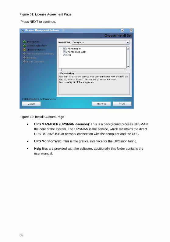
66
Figure 61: License Agreement Page
Press NEXT to continue.
Figure 62: Install Custom Page
UPS MANAGER (UPSMAN daemon): This is a background process UPSMAN,
the core of the system. The UPSMAN is the service, which maintains the direct
UPS RS-232/USB or network connection with the computer and the UPS.
UPS Monitor Web: This is the grafical interface for the UPS monitoring.
Help files are provided with the software, additionally this folder contains the
user manual.

67
Figure 63: Pre-Installation Summary Page
Figure 64: Installing UPSMAN
Selection of the UPSMAN start:

68
Figure 65: UPSMAN Start Selection
Click the „Next“ button to continue.
Press DONE to continue with UPSMAN graphical configuration. It is required to allocate a
password, which will be requested prior of the calling of the configuration, because a
remote configuration is also available.
Figure 66: JUPSCFG – Authorization
The system requires a moment to startup the graphical configuration (“./JUPSCFG”).
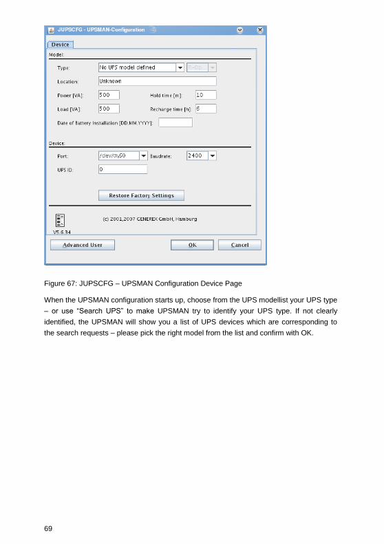
69
Figure 67: JUPSCFG – UPSMAN Configuration Device Page
When the UPSMAN configuration starts up, choose from the UPS modellist your UPS type
– or use “Search UPS” to make UPSMAN try to identify your UPS type. If not clearly
identified, the UPSMAN will show you a list of UPS devices which are corresponding to
the search requests – please pick the right model from the list and confirm with OK.

70
Figure 68: Select UPS Model Page - call “startupsman –config” for reopening this page
Serial interface
You have to choose now the correct serial or USB interface where the UPS cable is
connected. NOTE: If you use a USB-2-serial converter, youre interface will appear as tty –
not as USB.
The identification of the correct serial device name on UNIX is not easy to find . The
following table gives the usual device names for some popular UNIX systems.
Unix system Normal device name for the
first interface
For the first serial
interface
Linux /dev/ttyS0
HP UX /dev/tty0p0
SPARC /dev/ttya
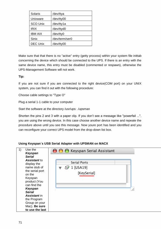
71
Solaris /dev/ttya
Unixware /dev/tty00
SCO Unix
/dev/tty1a
IRIX /dev/ttyd0
IBM AIX /dev/tty0
Sinix /dev/term/ser0
DEC Unix /dev/tty00
Make sure that that there is no "active" entry (getty process) within your system file inittab
concerning the device which should be connected to the UPS. If there is an entry with the
same device name, this entry must be disabled (commented or respawn), otherwise the
UPS-Management Software will not work.
Tip:
If you are not sure if you are connected to the right device(COM port) on your UNIX
system, you can find it out with the following procedure:
Choose cable settings to "Type O"
Plug a serial 1-1 cable to your computer
Start the software at the directory /usr/ups: ./upsman
Shorten the pins 2 and 3 with a paper clip. If you don’t see a message like "powerfail ...",
you are using the wrong device. In this case choose another device name and repeate the
procedure above until you see this message. Now youre port has been identified and you
can reconfigure your correct UPS model from the drop-down list box.
Using Keyspan´s USB Serial Adapter with UPSMAN on MACX
1) Use the Keyspan Serial Assistant to display the name stub of the serial port on the Keyspan product (You can find the Keyspan Serial Assistant in the Program Group on your Mac). Be sure to use the last

72
displayed name in the list. The name of the serial port in our example screenshot is: “KeySerial”.
2) Depending on your Keyspan product the serial port name maybe be extended by additional characters. To display the real device name that is used by your Mac: Open a Terminal windows and execute the following find command
“ls
/dev/*Key
Serial*”.
This will
display a list
of the
Keyspan
port(s) on
your Mac.

73
3) Now type the device name from above in the Port Configuration field, in our example:
“/dev/cu.Ke
ySerial1”.
4) Click the OK button to save the configuration and restart UPSMAN to listen on this Port.
USB interface
If you want to use an USB interface, just enter “USB” into the “Port:” area.

74
Figure 69: USB configuration
Finishing installation and basic configuration
After having choosen the correct UPS type and serial/USB device the UPSMAN standard
installation is finished. If you press now OK, the UPSMAN daemon will ask to start – press
YES to make the service/daemon start. If no further error message appears within 1
minute, the UPSMAN will now watch the UPS and send messages in case that an alarm
occurs. If the UPS runs on battery and the battery have only 3 minutes left (“downtime”),
the UPSMAN will automatically shutdown this computer. In case of alarms a messagebox
will pop up similar to the one above and the user can connect with UPS VIEW, UPSMON
or any other graphical viewer to see the actual UPS alarms.
4.1.1 Silent Installation of the UPSMAN Installation
The UPS Management Software provides a silent installation, but it is required to enter
some settings into the “installer.properties” file. This file is located into the CD folder
\Upsman\Linux\OEM-ID (2 for AEG, 3 for Piller etc.).

75
Figure 70: Content of the „installer.properties“
It is required to remove the hash mark prior of the variable INSTALLER_UI=silent. In
addition the setting of the license key is required behind the variable GXLICENSEKEY=.
Execute the “installupsman.bin” as root.
If you want to activate the console installation, it is required to remove the hash mark prior
of the variable INSTALLER_UI=console and to set the word console instead of silent.
The UPS Management Software 5.8.04. or higher provides the parameter preselection
for the UPS communication. Remove the hash mark prior of the variable
UPSDEVICE=/dev/ttyS0:2400,e,8,1, and adjust the parameters accordingly.
4.2 Start UPSMAN on UNIX and MACX
General
After the configuration has been done, the installscript will ask to start the UPSMAN
service.

76
To start / stop the UPSMAN process use always the prepared script ./startupsman. For
starting the UPSMan with all its necessary processes and services type
“./startupsman start”
To stop the processes call the script with the parameter stop as follows:
“./startupsman stop”
By “./startupsman config” you open the JUPSCFG graphical configuration page again.
Automatic Start at Server Boot
Every Unix system has a certain method to start programs at the boot procedure. Usually
a main start-up script or program reads off specific directories (e.g. /etc/rc1.d, /etc/rc2.d,
etc.) and executes the enclosed shell scripts. If you use this method you can start the
UPS-Management Software at system boot time automatically. The UPSMAN installation
will enter a new startup script (and remove older ones) automatically. In the Appendix you
find a section which describes the technical details of such a startup script so that you
may change it yourself.
4.3 UNIX WEB-Server
The Unix WEB SERVER offers the possibility to display all UPS data with a platform
independent WEB-Browser. In order to establish a connection from a WEB-Browser to a
UNIX WEB SERVER, please enter the IP address and a port number. Example:
http://192.168.202.91:8081. Port 8081 is used as a standard at the start up of the server.
Please adjust the script /usr/ups/startupsman.sh, if you would like to use a different port. It
is possible to start the Web-server with different port addresses, if several UPS monitor a
Unix server.
Start the WEB-Server by executing the script /usr/ups/upshttpd.sh
When connecting with your browser a graphical UPS viewer will open and show the UPS
data according to the specifications of the UPS maker.
The Webserver interface are varying for every OEM – following some examples for such
interfaces. All interface have in common that they are mainly viewers, so not essential for
a UPS/USPMAN installation.

77
Figure 71: Protect 3.33 UPS Webinterface
NOTE: For installations without a grafical interface (runtime level 2 or without KDE or other
desktop) – we provide a non grafical UPSMON through the commandline. For syntax
please refer to chapter 3.8.7, page 87.
4.4.1 Advanced User - DEVICE Page
The graphical configuration is started by “./startupsman config” – the JUPSCFG
windows is opened automatically and the user has to choose the correct UPS model –
similar to the windows configuration described above. You may reopen the configuration
at anytime by entering ” ./startupsman config” again. The DEVICE page shows a drop-
down list of UPS models which is the most important part of the configuration, because
with the model name links the correct UPS RS-232/USB protocol wioth each other. If a
wrong model is chosen from the list, the UPSMAN can not start.
The configuration may also be started from the user account from which the installation
was performed, the install.bin creates a link to startupsman config automatically (default).
From other user accounts the configuration can be started from the command line in the
/usr/ups directory “.startupsman config”.

78
Automatic start at server boot: The default of every UPSMAN is to start automatically at
every new server boot. If you want to change this, edit your startup script entries in /etc/rc
directoy.
Selecting the UPS-Model: To select your UPS-model, click with the mouse on the scroll
box symbol on the right side of the model list. Next, choose the UPS model that you want
to install. All other adjustments which correspond with your selected UPS model will be
done automatically, if the UPS has serial or USB communication.
We recommend NOT to change the default settings of communication parameters of the
UPS – most UPS have a fixed baudrate which must not be changed.
Set battery health level in % - The UPSMAN version 5.7.3 or higher provides an option
for UPSs, which are not able to give a result after a battery test. The default is 10%, that
means, if the battery voltage got a difference of more than 10% PRIOR of the battery test,
an error will be logged. Advice: Always execute a battery test with load. Please use the
nominal load, which will be present in normal mode.
UPS models with serial connections do not need additional adjustments, because these
models transfer all values to the UPS-Management software.
Figure 72: Advanced User – Device Page

79
4.4.2 Advanced User – Menu SYSTEM Page
Beside the UPS configuration page, more pages will appear if you click the “Advanced
User” button. All configuration data in the menus have "tool tips" in the corresponding
language. Every menu feature will be explained "online", following we start to describe the
SYSTEM page of UPSMAN.
Figure 73: Advanced User - System Page
UPSMON Password: Default - no password - The user may enter here a
password, which will be requested whenever any UPSMON or other graphical
interface tries to connect.
UPS Check Rate (s): Defines the timing (in seconds) of the polling data from the
UPSMAN to the UPS. The system will be slowed down, if this value is too small,
because of continous communication with the UPS. If the value is too high, the
system will react more slowly in case of a power failure. For continous use we
recommend a value between 15 and 30 seconds.
Enable Local System Shutdown: Defines if the system will start the shutdown
routine in the event of a shutdown call from the UPS during a power failure. If
you disable this function, no shutdown will be performed ! In the case of a
shutdown, the internal event routine will close down all active applications. The

80
shutdown of the UPSMAN computers is following the sript in the file
shutdown.sh from where the shutdown programs will be started.
Down time: Defines how many minutes before the UPS battery is discharged,
that the shutdown procedure begins. This timing has to be large enough to
guarantee a proper shutdown of the system before the UPS is turned off.
Ensure that this value is calculated on a large scale: (e.g. with 10 minutes hold
time of the UPS, start the shutdown procedure at least 3 minutes (default)
before the batteries are empty (battery low).
Enable UPS Shutdown: (Default = on) When OFF, the UPSMAN computer will
not execute the shutdown file.
Initiate shutdown always after x minutes: This enables/disables the execution of
the shutdown after a period of time wherein the UPS is working on batteries.
UPS Down Delay (s): Defines how many seconds after beginning the shutdown
procedure (see Down time) the UPS will turn off.
UPS Restore Delay (s): Defines how many seconds after turning off the UPS
the system is turned on again. For most UPS types it is necessary, that the
power has been restored before the UPS has completely switched off. With
some UPS devices the entry "0" disables an automatic restart and the UPS
needs to be switched on manually.
Enable SNMP Support: Enables or disables the SNMP support. Please check in
the event log, if this function is properly started. A message "SNMP
communication could not be started" shows, that an error occurs. No message
means, that this function is working.

81
4.4.3 Advanced User – Menu Files Page
Event Logfile Filename:“upslog.txt” is the name of the event/alarm text protocol.
The default is a MS-Excel compatible CSV file format.
Data Log File: “upsdata.txt” – This file contains all UPSMAN variables ID 700 or
800 which are part of the message.dat.
Logfile max. Size (kb): Defines the size of the log files in KB.
Figure 74: Advanced User – Files Page
82
4.4.4 Advanced User – Menu Events Page
Actions and reactions to UPS events/alarms will be defined in the “UPSMAN Event
Manager”. The UPSMAN service can execute certain actions (jobs).
NOTE: Although the jobs in the joblist of the EVENT manager are executed top-down – but since every job has its own timer (eg. delayed, immediately, etc.), the priority of the jobs depend on the individual timers, not on the rank in the job list. If you want to change the rank of a job, you can drag & drop the job in this list, but still the individual timer remains unchanged.
Which events are configurable depends on the type of UPS. Every UPS contain individual
alarms, large UPS have usually more alarms than smaller UPS. The following section
explains the pre-settings of such an event list on the example of a 1 phase UPS.
In order to configure the event, click on the designated event and the “Event Jobs” list
opens. For every event there are pre-settings, most of them are log file entries and
RCCMD messages as traps. In the example there are three jobs configured for the event
„Powerfail” - 2 jobs will send out standard text messages, (can be edited in the
"Message.dat" file), whereas the 3rd event writes a message into the log-file. In order to
add a job, please click the “Insert” button and the following functions page opens.
The “Reset” buttons below are to reset the alarm counters of UPSMAN, visible in the
UPSMON or other graphical viewers (statistical information since the software has
started).
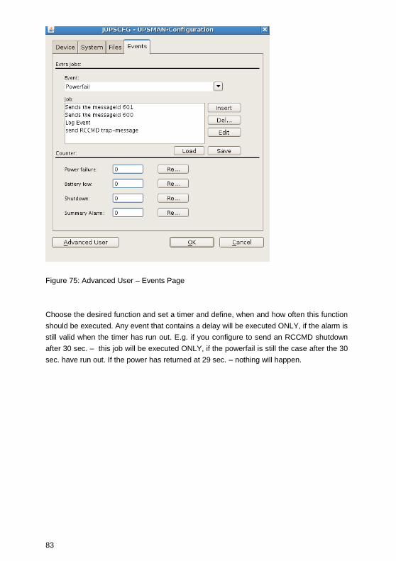
83
Figure 75: Advanced User – Events Page
Choose the desired function and set a timer and define, when and how often this function
should be executed. Any event that contains a delay will be executed ONLY, if the alarm is
still valid when the timer has run out. E.g. if you configure to send an RCCMD shutdown
after 30 sec. – this job will be executed ONLY, if the powerfail is still the case after the 30
sec. have run out. If the power has returned at 29 sec. – nothing will happen.

84
Figure 76: Advanced User – Insert Function Page
The following functions are available in most UPS:
Send a Shutdown UPS
Signal
Switches the UPS output off after a pre-set time.
Please make sure that the UPS is not being
switched off before a system shutdown is
executed, as otherwise important data may get
lost.
This shutdown signal only executes the output
switch off - but NOT the shutdown of connected
computers! If you define such an action, make
sure that RCCMD is triggered before! The user
can configure a delay (in seconds) before the
switch off is executed.
Send Message box with text Sends a network message to the user at this
terminal. Enter a user or a machine name or use
the "*" character in order to send the message to
all users.
Send RCCMD SHUTDOWN to This is the most important function in this job

85
remote client
list, it sends a RCCMD shutdown message to
RCCMD clients in the network! RCCMD
(Remote Console Command) is a program used
for the execution of executable files via network,
mainly used for the remote shutdown of
computers with different OS using TCP/IP as
common basis. From RCCMD Version 2.0 it is
possible to use the (*) as wildcard to shutdown
complete segments, e.g. 192.168.202.255 will
send the signal to all computers in the network
192.168.202.0 to 255. RCCMD can be used as
client (receive a signal) and a server (transmitting
a signal). So, the syntax to send a shutdown
signal to a specific computer is “RCCMD –s –a
192.168.200.201” - This example will send a
shutdown signal to this IP which will be executed
if on this IP also an RCCMD client is running and
the sender is in the valid address list of senders.
The entry of a IP address or hostname will send
RCCMD only to those named. If it is required to
shutdown more than one client, additional event
jobs can be configured. Note: If the number of
additional RCCMD clients is very large, a batch
file, which contains the RCCMD –s commands
can be used instead (“rccmd relay”). This allows
you to send rccmd calls much faster and is easier
to handle than the executing of a long list of jobs
by the UPSMAN. Such a scriptfile can be
executed from the “Special” or “Events Execute
Program” functions.
Please note that RCCMD shutdown calls should
always be configured in the “UPS Battery low”
without any further delay.
Send email
Sends an individual email text at this event.
Enter an email address and the corresponding
text into the field. Please note that you need a
configured SMTP server on the UPSMAN
computer. “sendmail” is the email program which
is triggered by UPSMAN email configuration.
Please make sure that sendmail is configured
correctly before using email.
Send RCCMD EXECUTE to This action initiates the execute.bat on a defined

86
remote client RCCMD remote client (IP-address). Through this
function the UPSMAN can execute any
command on the remote computer if the correct
path and name of the program is known on this
remote computer with RCCMD running.
Send RCCMD MESSAGE ID
to remote client
In this menu the user can send an ID from the
messages.dat to other users. These IDs are pre-
defined text messages. Open the file
message.dat to see the default text of such
messages. Text entries can be altered with an
editor. The edited text is then given out in a
textbox at the remote client. This is useful if you
want to send a messagebox from Windows
UPSMAN to a UNIX system - the problem of
sending messages to different operating systems
can be solved through this.
Start Alarm Beeper with
messagebox
This function displays a message box with an
audible warning on the screen of the UPSMAN
computer.
Send RCCMD MAIL ID to
remote client
Similar to RCCMD message ID, a message ID is
send, which is then forwarded from the RCCMD
client as an email to the corresponding receivers.
This is useful if the UPSMAN computer for any
reason can not send emails directly, than the
remote client can do this job. The user can pick
on of the default text messages as ID no. from
the file message.dat or us RCCMD MAIL TXT
instead to create its own text.
Send RCCMD MAIL TXT to
remote client
Like the send RCCMD mail function, an email is
send from the RCCMD client as relay. The user
may enter here any individual text.
Send RCCMD LOG TXT / LOG
ID to remote client
This writes a log file text (customized or as
predefined text if you use ID) into the RCCMD
remote clients log file. This maybe useful if a
common log file is wanted, where all UPSMAN
computers write into. This log file may be on any
network computer with RCCMD.
Send RCCMD MESSAGE (ID
or TEXT) to remote client
The user can configure a text message
(customized or as predefined text if you use ID)
which is transferred to the RCCMD client and

87
pops up as text box. This is useful if you want to
send a messagebox from Windows UPSMAN to
a UNIX system - the problem of sending
messages to different operating systems can be
solved through this.
Execute Program
Executes a configured program on this
computer. Please enter the full path to the
executable file on the UPSMAN computer. It is
recommended that the executable file is located
in the UPSMAN folder or in any other folder
where a path is set to.
Write to Log file
UPSLOG.CSV
Writes any text into the upslog.csv text file on
this UPSMAN computer.
Send default messages IDs
from file messages.dat
Sends pre-set network messages, using the
receiver name and message ID. This standard
message can be configured in the "message.dat"
file. Open the file with an editor in order to
change or check the text of the corresponding
message ID.
Send RCCMD trap message
by ID
This function enables UPSMAN to send
RCCMD2/UNMS traps, which shows the UPS
status as a text message on the remote client. If
activated it will display a local message box on
the client whenever the UPS status changes.
Please also note that the “RCCMD2/UNMS trap
enabled“ box is activated at the RCCMD client
to receive the trap messages.
Send RCCMD trap message Identical to RCCMD trap messags by ID, but the
user may define his own text.
4.4.5 Remote UPSMAN Configuration
To accomplish the remote UPSMAN configuration onto a system without grafical interface
via web-browser, it is required to start the UPSHTTPD onto the system, where the
UPSMAN is installed:
/upsman_path# ./upshttpd
Open a web-browser on a random system and enter the following into the address line:

88
http:/IP_Console_System:8081/jupscfg.html
It is required to install the JRE (Java Runtime Environment) PlugIns onto the system,
where you want to start the remote connection and enable the option „Allow Starting Of
Applets“.
4.4.6 Older “Install” Script Based Installation with “ups_conf”
This “install” script runs also without a graphical interface but is not supported for new
UNIX/MACX versions. We recommend to use for new OS the graphical installation, which
is almost 100% identical to the windows version, described above.
INSTALL Script based installation
The software is distributed on CD ROM or as downloaded TAR file from the internet. In
both cases you find (after mounting CD ROM or having the file unpacked tar –xovf …) you
find a new directory UNIX or GENEREX which contains the “install” script and the install
executable for the graphical installation. To start the script installation you have to use
“install” .
Tip: CD Rom instalaltion: On UNIX itself you need a CD-ROM drive and a CDFS
filesystem driver (ISO 9660). If there is no CD-drive on the system where the software
could be installed from, you can use any other Unix-system or PC with a CD driver (via a
network) to install the software.
Other way: Use a DOS- or Windows workstation in your network and insert the CD there.
Now you can copy the software (e.g. via FTP) to the hard drive of your Unix-system, /tmp
directory. For that purpose, copy the complete Unix-directory-tree.
The Unix part of the UPSMAN modules is found in the Unix directory. As there is no
standard binary executeable format for non graphical installations for all the different Unix
systems, we use a shell script to install the software onto your computer. Usually this
shell script should have executable permissions. If permissions are set correctly on your
CD ROM drive, you can start it directly from CD-ROM. In other cases you have to copy the
UNIX folder on your system and use “chmod” to make the “install” script executable.
Using the install script, only the UPSMAN modul command line based version of the
UPSMON (scripting tool to read/write to the UPSMAN module, eg. for reading variables
like UPS batteryvoltage, start tests, etc.) will be installed on your Unix system.
Please make sure you have root user rights in order to proceed with the installation using
the install script :
Step 1: Insert your CD - If the reading of the CD file
format is not supported by your system, proceed
as described above.

89
Step 2: Mount CD ROM - The first step you have to do
after inserting the CD-ROM into your CD-ROM
drive is to mount this device, i.e. give the system
access to the files at the CD-ROM. The comon
command at Unix systems to mount the CD-ROM
is like this: mount cd-rom-device mount-directory
However, there are serveral specific options for
this command depending on the used Unix
system. The following table displays these
options, but please check yourself if this matches
also for your system and OS:
Unix Options device name
Linux -o mode=777 -t iso 9660 /dev/cdrom
Sinix -F hs /dev/ios0/sdisk(id)s0
Reliant UNIX -F hs –o dos,ro /dev/ios0/device/cdrom
HP UX -F cdfs -o cdcase,ro /dev/dsk/c0t(id)d0
SCO Unix -oro /dev/cd0
Unixware -F cdfs –r o fperm=777 /dev/cdrom/c0b0t(id)l0
DEC Unix -f cdfs -o noversion /dev/rz(id)a
SPARC -F hsfs –r /dev/dsk/c0t(id)d0s2
Solaris -F hsfs –r /dev/dsk/c0t(id)d0s2
IBM AIX -o ro -v cdrfs /dev/cdrom
There are two possible case modes of filenames
at your CD-ROM: all file names are upper or
lower case. This has to be noted when you call
the installation programm or when you change
the subdirectory at the CD-ROM. The ISO 9660
specification supports also version numbers at
filename, so at some systems you will find
suffixes ";" (semicolon) or "." (dot) with filenames.
As you can abbrivate filnames with wildcards "*".
After successfully mounting the CD-ROM into
your system, you can start with installation by
calling the install script, i.e.
Step 3: Start the instal script - As a next step, please
start the install script install by entering: (”./install”
or ”../install” from the CD/Unix directory). In case
your CD file system does not support the
execution please copy the complete Unix

90
directory tree to e.g. /TMP and change with
CHMOD the execution rights of the install script.
Start the the installation with ./install again. The
procedure can look like this for e.g.:
cd /CDROM
cp -pr unix/ /tmp
cd /tmp
chmod +700 inst*
./inst*
Step 4: Enter UPSMAN license key - Please enter your
CD-key at this point and choose the desired
operating system from the list. The installscript
tries to recognize your OS and shows a list of OS
versions to choose from. The found system is
already preset and you simply need to confirm
the with a “Y” or RETURN.
The installation script will copy all required files
into the default directory /usr/ups. ( If you move
manually the installation directory later, don’t
forget that also the startup scripts have to be
changed ! Edited the scipts in the directory
”/etc/rc2.d” , the start/stop scripts usually carry
the names ”S99upsman” andr ”K99upsman”.
This is necessary because these files contain
reference to the directory ”/usr/ups”.
Step 5: Configuration tools - After the files have been
copied to the system, the configuartion program
starts automatically. Per Default the JAVA based
configuration will be started (“./startupsman
conf”). On as UNIX with a grafical shell the JAVA
UPSMAN configuation tool starts and the
configuration and look & feel is identical to the
WINDOWS version as described above. If no
grafical interface is present the user may use the
former on CURSES based configuration tool
“./ups_conf” . This tool has a different look and
feel compared to WINDOWS, so we describe in
the following this tool and not the JAVA based
configuration.

91
NOTE: ups_conf is not longer supported since CURSES
libraries do not exist on most modern UNIX. If
your system does have a GUI – nor supports
CURSES – you may configure your UPSMAN via
a network computer (eg. Windows) with a
Webbrowser and JAVA runtime.
The software is now extraced and installed, the basic configuration of UPS model and
interface is the next step.
“ups_conf” - Basic - Device Configuration
As described in Step 6 .- the grafical configuration is identical to the Windows UPSMAN
configuration described in this manual and is self-explanatory. In the following pages we
focus only on the older CURSES based version “ups_conf” which is no longer supported
but may be needed if no graphical interface is present of if you configure a no longer
supported OS version of UPSMAN.
After a successful extraction through the installscript “install” the UPS-Management
Software tries to start the graphical configuration “JUPSCFG” – if this fails and you can not
use any other computers Webbrowers to connect to this UNIX machine (HTTP://<IP
address>:8081) , you may fall back to the configuration tool “ups_conf” which is found in
the target installation folder (default /usr/ups).You can start this tool again by typing:
“./ups_conf” in the folder /usr/ups.
All configuration tools use the same config file “ups.cfg” which may also be changed by an
Editor, but some technical knowledge is required here and you may need the help of our
support. The ups_conf will ask you to create this file if it does not exists.
The file ups.cfg contains the configuration data and has to be in the same directory as that
in which the UPSMAN process is started from.
Within the configuration program ups_conf the ?-keyis available to read the help texts and
the Esc-key is available to close the menu. Finally do not forget to save your settings and
restart UPSMAN.
We continue with the “ups_conf” configuration with Step 7 – configuration of the UPS
comport and interface. Choose in the ups_conf menu “Set Ups values” to enter youre
Ups model and interface.
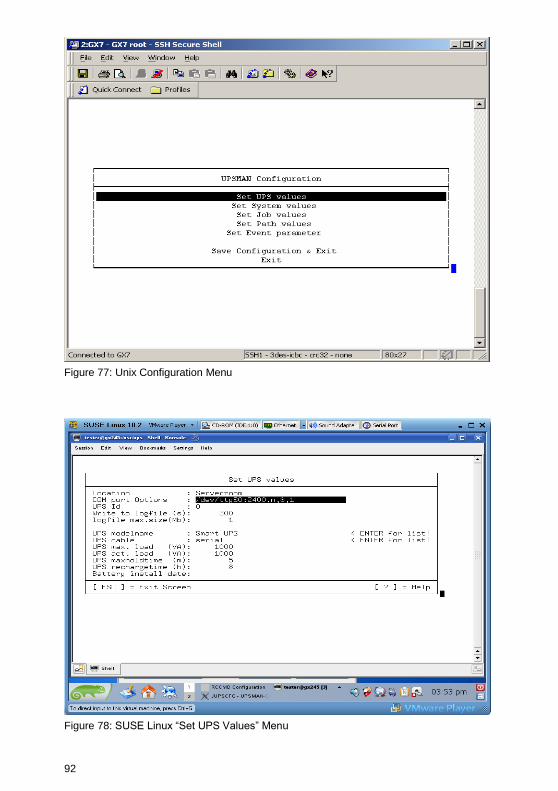
92
Figure 77: Unix Configuration Menu
Figure 78: SUSE Linux “Set UPS Values” Menu
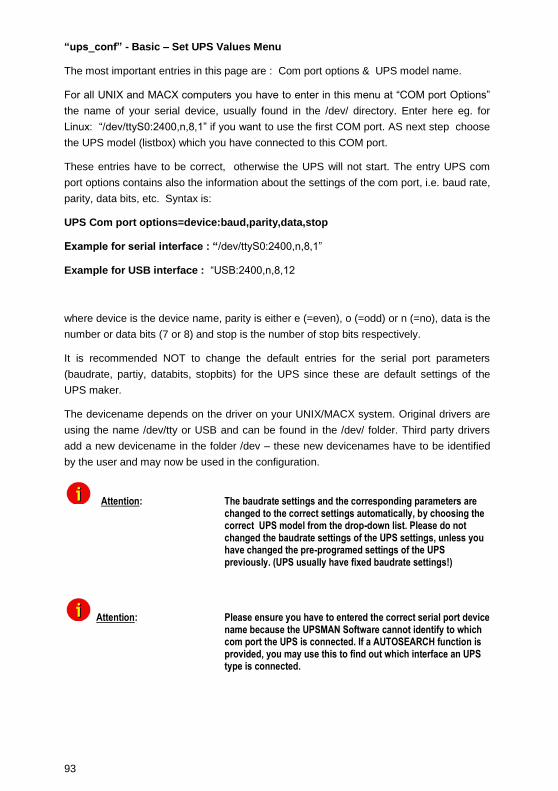
93
“ups_conf” - Basic – Set UPS Values Menu
The most important entries in this page are : Com port options & UPS model name.
For all UNIX and MACX computers you have to enter in this menu at “COM port Options”
the name of your serial device, usually found in the /dev/ directory. Enter here eg. for
Linux: “/dev/ttyS0:2400,n,8,1” if you want to use the first COM port. AS next step choose
the UPS model (listbox) which you have connected to this COM port.
These entries have to be correct, otherwise the UPS will not start. The entry UPS com
port options contains also the information about the settings of the com port, i.e. baud rate,
parity, data bits, etc. Syntax is:
UPS Com port options=device:baud,parity,data,stop
Example for serial interface : “/dev/ttyS0:2400,n,8,1”
Example for USB interface : “USB:2400,n,8,12
where device is the device name, parity is either e (=even), o (=odd) or n (=no), data is the
number or data bits (7 or 8) and stop is the number of stop bits respectively.
It is recommended NOT to change the default entries for the serial port parameters
(baudrate, partiy, databits, stopbits) for the UPS since these are default settings of the
UPS maker.
The devicename depends on the driver on your UNIX/MACX system. Original drivers are
using the name /dev/tty or USB and can be found in the /dev/ folder. Third party drivers
add a new devicename in the folder /dev – these new devicenames have to be identified
by the user and may now be used in the configuration.
Attention: The baudrate settings and the corresponding parameters are changed to the correct settings automatically, by choosing the correct UPS model from the drop-down list. Please do not changed the baudrate settings of the UPS settings, unless you have changed the pre-programed settings of the UPS previously. (UPS usually have fixed baudrate settings!)
Attention: Please ensure you have to entered the correct serial port device name because the UPSMAN Software cannot identify to which com port the UPS is connected. If a AUTOSEARCH function is provided, you may use this to find out which interface an UPS type is connected.

94
UPS model: Goto the UPS model list and choose from the listbox the UPS type which
you have connected to your interface. If you can not find the UPS model in this list, check
if you have installed the correct software OEM version for this UPS maker.
Corresponding to the UPS model you have selected the UPSMAN Software has
automatically set the UPS parameters and the corresponding “UPS cable” type.
UPS cable: In general there are three different UpsCables which are automatically
assigned by the UPS modelname:
Serial setting: (Default for all modern UPS with a serial or USB protocol). The UPS-
Management Software uses a data protocol to get status information from and to send
commands to the UPS. For such protocol types the original UPS cable has to be used.
Cable 2 to 13: With these settings the UPS-Management Software uses modem control
connection to get the status from the UPS, e.g. the UPS sets a signal "high" or "low". In
this case the software is only able to get the status "Powerfail" and "Battery Low" and to
shutdown the UPS immediatly. The cable settings 2 to 9 are not very appropriate for non
X86/x64 based UNIX because they do not support modem control exploitation. If you use
any x86 based UNIX, we recommend to use cable logic 2. However – supported in every
UNIX are the cables types “C” ”closed” or”O” ”opened”.
Typ O and Typ C: This is the most simple form of a dry contact monitoring - in this case
the software sends a byte to the UPS and tries to get it again via the usual send/receive
wires. In the case of Type O (=open) the contact is open, so the the send byte can not
return in normal UPS operation. The moment the contact closes (Ups Alarm) the byte
returns and the UPSMAN triggers the Powerfail EVENT. The logic is other way round in
the case of setting cable type to Typ C (=closed).
Other configuration Parameters on page “Set Ups values”
Write to logfile Defines the time-interval (in seconds) the UPS-
Management Software logs the Input Voltage and
Frequency Values. The standard entry to the text
file (Ok status) are done every 15 minutes, if no
unusual Events occur.
Logtime min. Defines the minimum time-range (in hours) of the
Logfile for Input Voltage and Frequency Values.
Logfile Size max. Defines the maximum time-range (in hours) of the
log file for Input Voltage and Frequency Values.
The log file will be set back to min. size (value of
logfile size min.) if the log file contains more data
than the configured value.

95
“ups_conf” - Basic – Set System values
Check UPS interval Defines the time-interval (in seconds) that the
UPS-Management Software polls the UPS for
new data via the serial port. The system will be
slowed down due to permanent communication
with the UPS if the value is too small. If the value
is too high the system will react more slowly if a
power failure occurs.
Enable shutdown Defines if the system will start the shutdown
procedure in case of a power failure.
ATTENTION: Make sure that this entry needs to be ”yes” at all times, if there are no customised shutdown jobs configured. This is to avoid that the UPS switches off before the system has performed a shutdown proberly.
System downtime Defines how many minutes before the UPS-
battery is discharged the shutdown procedure is
initiated. This time-interval has to be large
enough to guarantee a graceful shutdown of the
system before the UPS is switched off. Calculate
the value on a large scale: (e.g. with 10 minutes
hold time of the UPS start the shutdown
procedure at least 3 minutes before the discharge
of the battery).
The following functions are not supported by all UPS types. In particular, devices with the
connection-type cable do not support a scheduled down and restore command.
Shutdown UPS Defines if the UPS will be turned off on
completion of the server shutdown procedure.
This command will turn off the UPS before a
complete discharge of the batteries.
UPS shutdown delay Defines how many seconds after beginning the
shutdown procedure (see Downtime) that the
UPS will turn off.
UPS restore delay Defines how many seconds after turning off the
UPS the system is turned back on again. For
most UPS types it is necessary that the power

96
has been restored before the UPS has
completely switched off.
Enable fixed shutdown Defines if a shutdown needs to be initiated after a
power fail, independent from the remaining time
of the UPS and the configured system down time.
Fixed shutdown delay Defines after how many minutes a fixed
shutdown should be initiated.
The basic configuration is now complete. Exit the menu (ESC) and leave config tool by
Save Configuration & Exit. The UPSMAN may be started now.
“ups_conf” - Advanced User – Set Job values
Following part of this manual explains the Advanced User configuration items of UPSMAN
software, using the “ups_conf” tool.
This analogue to the Windows description “ Special Jobs” and allows the execution of
own programs, e.g. shell scripts at a defined point of time during the discharge of the
battery. As soon as the UPS transmitts a "Remaining Time" which equal or lower than the
configured value, the corresponding procedure is executed.
As soon as the "Enable Extra Job“ is set to "yes“, the program name or shell script of the
desired job can be entered in the "Extra Job x (Path)“ line. This script is than started at a
certain set Remaining Time of [m] minutes.
Example: Different network servers should be stopped at different times via shutdown
script, depending on the importance. This way it is possible to provide (depending on the
circumstances) more autonomy time for the important components.
Additionally 3 jobs can be executed time controlled.
Path for textfile Defines the filename and path of the event log.
Path for datafile Defines the filename and path of the log file for
Input Voltage and Frequency Values.
Path for custom file Defines the file name and path of the custom file

97
Figure 79: Defining Paths
“ups_conf” - Advanced User – Set Event Parameter
The UPS Events enables the user to utilise and configure the different applications of a
UPS. Depending on the matter of use, via Events (Event messages of the UPS) certain
actions (Jobs) can be executed with the UPS-Management software. Via an Event it is
possible to transfer measured values, status messages to own processes, in order to
process those even further (e.g. load statistics etc.). The Event configuration starts from
the UPSMAN configuration. (see picture)
Figure 80: UNIX ups_conf Events Menu
In this part of the configuration, the event parameter will be configured. The user can now
choose a event, which needs configuring. (see picture below)
Which Events are configurable depends on the type of UPS. The standard messages,
which can be used, can be found in the file "message.dat" in the UPSMAN directory.

98
Figure 81: UNIX ups_conf Event List
In order to process the Events, please go to the Eventlist in the UPSMAN configuration.
There is a pre-set (default) for every Event. In the above example, the event “UPS/System
shutdown imminent...“ is configured with 3 default jobs. The first will send a standard
message (message id 603), which can be edited in the messages.dat file. The second job
will write the event into the log file of the UPS-Management software, whereas the third
job will execute a shutdown after x minutes (default).
Add Event Job:
In order to add a Job to event, please highlight the corresponding event and confirm with
the “Enter” key. In the following window, the “Add Job to List” a additional job can be
added. By using “Delete Job from List“, a single event job can be deleted from the list.
“Exit menu” will take the user back to the Eventlist windows. (see picture)
Figure 82: UNIX ups_conf Menu – Add Job Parameter

99
Please choose the desired function and set when and how often this function should be
executed. Please note listed functions depend on the used operating system and not all of
them might be available. In this case please refer to share or freeware programs, which
allow the desired function. The following jobs can be added to a event.
Send a Shutdown UPS
Signal
Switches the UPS off after a pre-set time. Please
be aware that the UPS is not being switched off
before a system shutdown is executed, as
otherwise important data may get lost.
This shutdown signal only executes the switch
off, of the UPS, but not the shutdown of
connected computers. The user can configure a
delay (in seconds) before the switch off is
executed. This is recommendable when a
switching off of an UPS is necessary because of
over-heating etc.
Send Message box with text Sends a network message. Enter a user name or
use the "*" character (not with NetWare), in order
to send the message to all users. Please note
that the Windows 95/98 Clients NT message can
only be only received if Winpopup.exe or another
message service is active. Please also consider
that "net send * <text> "with Windows 95/98 does
not function correctly. Instead of the " * " a
respective machine name e.g. "Workstation1"
must be entered. In order to send messages to
several users a "Send Message" job must be
inserted per user. Please note that the Windows
NT user database is not empty and that the
computer belongs to a domain, as otherwise the
network messages can not be sent.
Send RCCMD SHUTDOWN to
remote client
RCCMD (remote console command) is a
program used for the execution of executable
files via network. This tool transmits a TCP/IP
signal that is absorbed of the recipient module
(RCCMD client software) on another computer.
This function is normally used for sending a
shutdown command (call of shutdown.bat) over
the network to another computer, of any
supported operation system. (starting from CD
4.17).
From RCCMD Version 2.0 it is possible to use

100
the (*) wildcard or other syntax. For example
192.255.255.255 will send the signal to all
computers in the corresponding subnets. A
RCCMD –s –a 192.168.200.255 will send the
signal to all computers in the subnet 200. The
entry of a IP address or hostname will send
RCCMD only to those named. If it is required to
shutdown more than one client, additional event
jobs can be configured. Hint: If the number of the
additional RCMD clients is too high, a batch file,
which contains the RCCMD –s commands can
be used instead. This much faster and also
easier to handle than the a long list of event job
list. This batch can be executed from the
SPECIAL or EVENTS EXECUTE PROGRAM
function.
Please note that RCCMD should always be
additionally configured in the “UPS Battery low”
Event and if the Event “UPS/shutdown
imminent....” is used, RCCMD must always be
located before the “shutdown UPS in default
seconds” command. For moving the command
lines, “click” with the left mouse on the line, hold
the button and now move the command.
Send eMail
Sends an E-mail. Here we use the SMTP email
client of your UNIX system “sendmail”. Configure
SENDMAIL first before you use this function !
Enter the E-mail address and the corresponding
text into the field.
Send RCCMD EXEUTE to
remote client
This action initiates the execute.bat on a defined
remote client (IP-address). This bat file can be
configured individually by the user. The user may
execute a random program on the remote client
computer, where the execute.bat is located. It is
also possible to attach parameters, whereas
these parameters must be added to the
execute.bat which is executed as described
above.
Execute Program Executes a configured program. Please enter the

101
full path to the executable file. Is the desired
executable the same directory as the
upsman.exe or *. nlm, no path entry is
necessary. The handling of other variables is
explained further on in this chapter.
Write to Log file
UPSLOG.CSV
Writes the Event into the local log file of the
UPSMAN computer
ATTENTION: Since ups_conf which is CURSES based is no longer supported, we recommend to use the graphical configuration JUPSCFG (Java based) for any configuration in the advanced user area.
4.4.7 Unix/MAC commandline UPSMON
The UPSMON for Unix is a simple monitoring tool for the display of the current UPSMAN
data and for the programming of own scripts for further processsing UPS information.
In addition all UPS functions and UPS tests can be activated by UPSMON:
Parameter for UPSMON
usage: upsmon {-vicdtrh} [-n start-number]
-v Program information
-i <value> Query of a UPS-measurement
-c <ups command> Execution of a UPS-function
-d <ups command with duration> <seconds> Execution of a timed UPS-function
-t <ups test> Execution of a UPS-test function
-r <ups test result> Query of a UPS-test functions result
-h Display of extended help
-n <start-number> Is a definite number, if more than one UPSMAN is running on the
Unix-machine (several UPS at one computer)
<values>: -i
status
inputvolt
inputcurrency

102
battvolt
temperature
autonomietime
autotime
battcap
batterycapacity
outputpower
inputfrequenz
outputfrequenz
<ups command>: -c
canceltest
cancelbatterytest
cancelshutdown (only certain UPS supporting this command)
alarmreset
bypassmode
shutdownrestore down seconds restore seconds
switchoutlet [0=off|1=on] [outlet nr]
<ups command with duration>: -d
shutdown
restore
cancelbypass
outputoff
<ups test>: -t
customtest
batterytest
selftest

103
fulltest
<ups test result>: -r
customtest
batterytest
selftest
fulltest
Example:
Command for read "autonomy time":
"./upson -i autonom"
Response from upsman :
"upsmon: Inquiry (autonomietime) ups answer: 25.48
Command for Shutdown UPS and Restore
-/upsmon –c shutdownrestore 90 120
Note: More information about the UPSMON modul is given in part III of this manual.
4.5 Apple MacIntosh
4.5.1 UPSMAN for MAC OS 9 – MAC OS 10
MAC OS 9 is no longer supported, only RCCMD should be used on such older MAC
systems. UPSMAN is currently only supported for MAC OS X 10.4 and higher. UPSMAN
on MAC X 10.4 and higher is identical to the UNIX UPSMAN description and installation.
UPSMAN for MAC X is designed for MAC OS 10.4 or higher. Its is using the same
installation routine as UNIX and WINDOWS.
UPSMAN for MAC OS X is identical regarding installation and configuration as the
UPSMAN for UNIX. Please refer to UPSMAN user manual for UNIX when installing
UPSMAN for MAC X.

104
The only difference in MAC X configuration compared to UNIX is the different device
name for the serial /USB interface. Since the device name for a RS232/USB interface is
created during the installation of eg. a USB to Serial adapter, the user has to find out the
device name for his new COM or USB port in the MAC X device finder.
5. UNMS – UPS Network Management System
UNMS is an additional viewing tool for UPS installations. It’s a UPS network monitor
designed to monitor your UPS devices on different locations in the network. This tool is
useful if you have more than 1 UPSMAN/CS121 to manage. For standalone UPS this
software is not needed.
The UNMS may be delivered as a limited versionwith the UPSMAN license (depends on
UPS makers license regulations). The UNMS Server Service runs intermittent checks on
UPS devices you specify. When problems are encountered, the UNMS Server Service can
send notifications out to administrative contacts in a variety of different ways (For
example: Email). Current status information, historical logs, and reports can all be
accessed via a web browser (Web Console).
Figure 83: UNMS II Environment
The UNMS is not described in this manual, a separate UNMS user manual is distributed
with the UNMS software or can be downloaded from WWW. GENEREX.DE
documentation download area.
6. Simple Network Management Protocol (SNMP)
The Simple Network Management Protocol (SNMP) is a worldwide standard
communication protocol. It is used to monitor any device in the network via simple control
language. The UPS-Management Software also provides its data in this SNMP format.

105
UPSMAN supports under Windows the private GENEREX MIB, found as MIB file in the
UPSMAN directory (“upsman.mib”). At Linux we support the RFC 1628 standard UPS
MIB which is present in most SNMP software already and does not need to be compiled.
With any SNMP-Management software (e.g. HP-OpenView, Novell NMS etc.) capable of
compiling an external MIB (UPSMAN.MIB) or having the standard RFC MIBs already
implemented – can now connect to the UPSMAN SNMP agent and read UPS data
The UPSMAN software supports the SNMP interfaces from Windows and Linux ( from
Kernel 2.5 and higher). On all other operating systems the UPSMAN does not have an
SNMP interface. For SNMP data on such OS we recommend to use an SNMP adapter
(eg. CS121) instead. In case you use a CS121, the UPSMAN software is obsolete since
already running inside the CS121.
6.1 UPSMAN with SNMP on Windows
To be able to connect to the UPSMAN via SNMP you have to install and configure the
Windows SNMP service.
Open the Windows Components Wizard (click Start, Control Panel, double-click
Add/Remove programs and then click Add/Remove programs again). In components, click
Management and Monitoring Tools (but do not select or clear its check box) and then click
Details.
Select the Simple Network Management Protocol check box and click ok.
After the SNMP service has been installed you have to configure the SNMP service via
the control panel icon Administrative Tools/Services. Enter the community string of your
management station and the address of the trap target and enter the system group.
Start the SNMP-service from the command line by net start snmp or start with the help of
the icon Services from the control panel. If the installation has been completed
successfully you should receive a cold boot trap on your management console. In addition
you can access system group data.
In order to connect the UPSMAN software and an SNMP adpter is it required to start the
SNMP service. The UPSMAN computer needs to be configured in the SNMP adapter.
Please also refer to your SNMP adapter installation manual.
The UPSMAN SNMP MIB RFC1356 is located into the „private tree“!

106
Figure 84: SNMP MIB Tree
6.2 UPSMAN with SNMP on LINUX
To install the UPSMAN SNMP agent under Linux, activate this option in the CUSTOM
installation. No futher configuration is required and you may read the UPS data through
SNMP using the RFC 1628 SNMP MIB.
7. FAQ
Problem with SuSE 11.3, x64: UPSMAN is running, remote configuration is possible, but
UPSView does not start (no error message into web-browser)
Solution: Manually installation of the libstdc++ 32bit with the following command:
yast –-install libstdc++-32bit
Problem email transmission on Windows OS: If the UPSMAN should not transmit
emails, you can get more information with the program qblat into debug mode. Enter the
following command out of the UPSMAN default folder C:\Program Files\UPS\upsman:
qblat.exe –debug –to (email address of the receiver) (text)

107
Figure 85: qblat Debug
Solution: Send the faulty output to [email protected]
Problem with Ubuntu 10.04 syslog messages: Since Ubuntu 10.04 rsyslog is used
instead of plain syslog.
Solution: Proceed as follows to discard messages from syslog:
Create the file /etc/rsyslog.d/01-blocklist.conf (the 01-part into the filename
forces rsyslog to load this config prior it loads anything else)
Add the line :msg,contains,”upsman” ~ (the lines into the file find any messages
containing the text you want to ignore and discard those messages right away
Restart rsyslog with /etc/init.d/rsyslog restart
Problem with the installation of multiple UPSMAN services on one PC:
Information: We do no longer support it (05/2011).
Problem with the installation on a 64bit UNIX OS:
Solution: If the installer is not running on a 64bit Debian/Ubuntu (GNU/Linux) system, it is
required to install the compatibility libraries with the following command: sudo aptitude
install ia32-libs
If the installer is not running on a 64bit Fedora 12 (GNU/Linux) system, please do the
following :
Open an editor, create a new file called „install“ and copy the following lines into it:
#!/bin/sh
libs_32=( libXext.i686 libXtst.i686
libstdc++.i686)
for lib in ${libs_32[@]}
do
yum install $lib

108
done
Call the command (as root), to install the required 32bit libs:
[terminal]:./install
Problem: No communication possible to APC UPS SURTD from 2011
Solution: This UPS model communicates with a proprietary protocol. It is required to use
the APC slot card Legacy (AP9620) for the establishment of a communication.
Problem: Mount of USB stick via command line
Solution: Change into the directory /dev. Execute ls. There you will see the connected
devices. Note the devices like sda, sda1… Connect your USB stick. Execute ls again into
/dev. Now you should see more entries under sda. My stick got the entry sdc1.
Enter the following : mount /dev/sdc1 /mnt
Use this command on FreeBSD OS : mount_msdosfs /dev/da0s1 /mnt/usb
Execute ls –lisa
Now you should the folders of your stick. Change into the accordant directory : cd
/mnt/name of the folder, which contains the installation data.
Extract the the upsinst.tar file : tar –xvf upsinst.tar
Execute the binary file : ./installupsman.bin
Appendix
A. Supported Systems
The UPS Management Software supports all current operating systems. Please use our
internetsite for updates and additional information. http://www.generex.de
B. Know-How Pool
In this section you will find a collection of know-how informationof different operating
platforms and operating systems. Please note that an update of to the latest version of the
UPS-Management software will solve many problems and minor "bugs". Please contact
your UPS dealer or visit our webs ite under http://www.generex.de The free update to the
latest version of the UPS-Management software is available from CD version 4.17.
Change UPSMAN Window start-up in the registry
This can be done by changing the script, please change the path:
Hkeylocal_machine\system\currentcontrolset\services

109
in the registry and find the entry start. This enrty should be set to 0x2 (automatic) by
default, 0x3 (manual) and 0x0 means that the driver will be loaded by the Kernel loader at
startup. However, 0x1 means that the dribver will be loaded by ethe I/O subsystem at
Kernel startup.
Change UPSMON Window PollRate
To change the PollRate of the UPSMON to the UPSMAN service, it is required to edit the
value (in seconds) into the file „upsmon32.ini“, which is stored into the default folder
C:/Program Files/UPS/upsmon:
Figure 86: UPSMON32.INI Edit
Example settings SUN Solaris 2.6, 2.7 : TTY configuration
Settngs of the serial interface with the admintool:

110
Figure 87: Example Settings SUN Solaris 2.6, 2.7 : TTY configuration
UPSTCP
This program connects the remote Windows or Java UPS monitoring software using the
local UPSMAN program. It must be started, if the you want to "connect" with the UPSMON
software to UNIX controlled UPS. This can be done within the ups.rc startup script. The
upstcp program is based on the TCP/IP network protocol. Any UNIX system has these
protocol implemented; there is no need to install TCP/IP separatly. UPSTCP has to be
started, if UPSMON for the graphical UPS monitoring is used.
CS122 Network Adapter:
When using the an older CS122 UPS network adapter instead of the serial port of the
UPS the following procedure must be followed :
Set the IP adress of the CS122 using ar webbrowser or telnet as described in the
Quickstart set-up for the CS122. Start "ups_conf". Go into the "Set UPS values" screen.
Replace all of the values in the field "COM port Options" uptil the colon with with the
CS122 connection:
For example: replace the Linux-Comport "/dev/ttyS0:2400,n,8,1" by the virtual CS122-
Comport "[email protected]:2400,n,8,1" Note that the values for the baudrate
and other values following the colon will automatically be set when changing the UPS
model.

111
Figure 88: Settings for a CS122 network TCP/IP to Serial converter (MOXA, or other)
(No longer supported) Virtual comport in the UPS values – NOT for CS121 ! The CS121
does not need to communicate with any UPSMAN software, the UPSMAN is part of the
CS121! This is only useful if you use a RS232 to TCP converter like the CS122 or devices
from MOXA.
HP OPENVIEW Bug_ RFC 1628 Trap receiver does not interprete correct
MIB 2 Traps
This bug is know in HP OV 5, 6 for Windows. The moment the trap definition is manually
changed, HP OV transforms the version 2 trap indentifier in to version 1.
How to override: You can manually correct in the trapd.conf file. You will see that the trap
ID has changed from
1.3.6.1.2.1.33.2.1 to 1.3.6.1.2.1.33.0.1 (this is trap 1 ! - not trap 2). Change this string
to 1.3.6.1.2.1.33.2.1 again to correct this problem.
HP OV Version 5 and 6 SNAP IN under HP UNIX:
Configuration for HP-OV-Snap-in:
in /etc/opt/OV/share/registration/C

112
the following file must be present: upsmonov.reg
After the reboot, the process upsmonov must be present in the process list. This process
incorporates normally all objects, which are SNMP supported and also support the
RFC1628-MIB or PPC-MIB.
Please check the following picture:
Figure 89: Configuration for HP-OV Javamon
In /etc/opt/OV/share/registration/C the following file must be present: upsmon.reg.
The following must be configured in the symbol properies for the object:

113
Figure 90: Symbol/ Object Properties
C. Automatic Start of the UPSMON after Reboot (Windows)
If the UPSMON should start after reboot automatically, it is required to link the supplied
„GO.BAT“ file, which is located into the default folder C:\Program Files\UPS\Upsmon,
into the startup of Windows.
Figure 91: „GO.BAT“ into startup

114
Figure 92: Properties of the „GO.BAT“ Link
D. NTP time synchronization (UNIX)
The Network Time Protocol is defined in RFC1305 and allows the transfer and
maintenance of time functions over distributed network systems.
Basic Configuration
The following command will synchronize the local system time against another server,
ensuring nearest possible time is available before configuring the NTP server:
[bash]#ntpd –b
If failed, try the following command:
[bash]#ntp –b

115
Figure 93: Bash – ntpd –b
Make a backup of the original file (/etx/ntp.conf):
[bash]#cp /etc/ntp.conf /etc/ntp.conf.original
Edit the configuration file and do the following changes :
[bash]#vi /etc/ntp.conf
The following declarations into the /etc/ntp.conf file are required :
#Finding a Time Source.
# The default configuration for ntpd servers after version 4.2 uses the NTP
#Pool for the default server sources.
Server 0.pool.ntp.org
server 1.pool.ntp.org
server 2.pool.ntp.org
# Access Controls.
restrict default kod nomodify notrap noquery nopeer
#The NTP Pool servers have been listed as a time source already (ver 4.2
#onwards), and they too need restrictions applied so the local server can
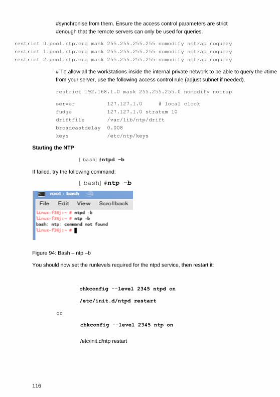
116
#synchronise from them. Ensure the access control parameters are strict
#enough that the remote servers can only be used for queries.
restrict 0.pool.ntp.org mask 255.255.255.255 nomodify notrap noquery
restrict 1.pool.ntp.org mask 255.255.255.255 nomodify notrap noquery
restrict 2.pool.ntp.org mask 255.255.255.255 nomodify notrap noquery
# To allow all the workstations inside the internal private network to be able to query the #time
from your server, use the following access control rule (adjust subnet if needed).
restrict 192.168.1.0 mask 255.255.255.0 nomodify notrap
server 127.127.1.0 # local clock
fudge 127.127.1.0 stratum 10
driftfile /var/lib/ntp/drift
broadcastdelay 0.008
keys /etc/ntp/keys
Starting the NTP
[bash]#ntpd –b
If failed, try the following command:
[bash]#ntp –b
Figure 94: Bash – ntp –b
You should now set the runlevels required for the ntpd service, then restart it:
chkconfig --level 2345 ntpd on
/etc/init.d/ntpd restart
or
chkconfig --level 2345 ntp on
/etc/init.d/ntp restart
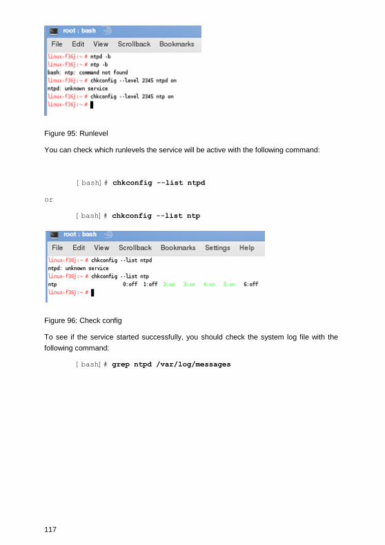
117
Figure 95: Runlevel
You can check which runlevels the service will be active with the following command:
[bash]# chkconfig --list ntpd
or
[bash]# chkconfig --list ntp
Figure 96: Check config
To see if the service started successfully, you should check the system log file with the
following command:
[bash]# grep ntpd /var/log/messages

118
Figure 97: Log messages
You can now query the NTP server with the ntpq (query) tool:
[bash]# ntpq –pn

119
Figure 98: NTP query
E. UPSMAN configuration without graphical interface (Linux)
Perform a “Silent Installation” (text-only output) on the Linux machine. Store the cd-data
into /usr/ups and start the UPSMAN web-server with the command ./upshttpd
Start a java-compatible web-browser on a machine with graphical interface. Enter the
following address:
http://<ip-or-name-of-upsman-machine>:8081/jupscfg.html
Enter the desired configuration data and restart the UPSMAN daemon. Done!
F. Error codes (UPSMAN)
List of the UPSMAN Error codes, which consist of 4 digits e.g. 4603 indicates an error at
the serial interface.
Severity information codes:
0xxx Success information
1xxx Severity informational
2xxx Minor error, warning
4xxx Major error, process stopped
Error type:
x1xx Unknown error

120
x2xx Out of heapspace
x3xx Module not installed
x4xx UPS protocol failure
x5xx Locked, failure during operation
x6xx Connection failure
x7xx Capability failure
x8xx UPS database error
Extended error information:
xxx1 Unknown error
xxx2 Error in installation
xxx3 Error at serial interface
xxx4 No communication with UPS,but COM port opened OK
xxx5 No answer from UPS within 3 seconds
xxx6 Incorrect data from UPS received
xxx7 Header of UPS protocol is missing or defect
xxx8 Checksum error in protocol string of UPS
xxx9 Unspecified error
xxxA UPS did not accept the command
xxxB End of command string or byte was missing
xxxC COM port could not be opened
The following error codes in table are displayed when the UPSMAN software fails to start.
Error
code
Error name Description
2 ENOENT No such file or directory
This happens if the device name is not found. The
reason can be a missing colon (":") at the end of the
device name
5 or 6 EIO /
ENXIO
No such device or address. I.e. the device name
exists, but the physical device does not. E.g. the
device name is /dev/ttyS2, but the computer has only

121
two serial devices.
22 EINVAL Invalid argument. The serial port driver of the UNIX
system does not support a function call the UPSMAN
programm.
25 ENOTTY Not a serial device. Please choose a device name
which is not a serial device.
G. Cable types
For UPS communication cable please refer to GENEREX website download
documentation or contact you UPS maker.
H. Picture catalog
Figure 1: UPSMAN and RCCMD in a network environment.............................................. 7
Figure 2: Introduction ........................................................................................................ 9
Figure 3: Enter your License Key .................................................................................... 10
Figure 4: Thirty-Day Trial Version without Key Code ....................................................... 10
Figure 5: License Agreement .......................................................................................... 11
Figure 6: Choose Install Folder ....................................................................................... 11
Figure 7: Choose Install Set ............................................................................................ 12
Figure 8: Choose Shortcut Folder ................................................................................... 13
Figure 9: Pre-Installation Summary ................................................................................. 13
Figure 10: Firewall Configuration ..................................................................................... 14
Figure 11: UPSMAN Tray ................................................................................................ 14
Figure 12: UPSMAN Configuration .................................................................................. 15
Figure 13: Select UPS Model .......................................................................................... 16
Figure 14: Windows Services .......................................................................................... 17
Figure 15: Protect 3.33 UPS Webinterface ...................................................................... 18
Figure 16: UPSMAN Properties ....................................................................................... 19
Figure 17: Select User .................................................................................................... 19
Figure 18: UPSMAN Properties – This account ............................................................... 20

122
Figure 19: Content of the „installer.properties“ ................................................................. 21
Figure 20: UPSMON Statuspage of a Protect 3.33 UPS.................................................. 22
Figure 21: Scheduler in UPSMON, interface to program actions on your UPSMAN ......... 23
Figure 22: UPSMON Statuspage of a Standard UPS without OEM Design ..................... 24
Figure 23: UPSMON Device Command Window ............................................................. 25
Figure 24: UPSMON Extended Commands Window ....................................................... 26
Figure 25: UPSMON Programmable Outlet Settings Window .......................................... 26
Figure 26: UPSView Remote Access .............................................................................. 28
Figure 27: UPSView Log File .......................................................................................... 29
Figure 28: UPSView Functions ........................................................................................ 29
Figure 29: UPSView Scheduler ....................................................................................... 30
Figure 30: UPSMAN Device Configuration ...................................................................... 32
Figure 31: UPSMAN System Configuration ..................................................................... 34
Figure 32: Message on RCCMD client when UPSMAN trap has been received .............. 35
Figure 33: Windows UPSMAN Shutdown Sequence Configuration ................................ 36
Figure 34: UPSMAN Files Configuration ......................................................................... 38
Figure 35: UPSMAN Mail Server Configuration ............................................................... 39
Figure 36: UPSMAN Event Config................................................................................... 40
Figure 37: Advanced Buttons ......................................................................................... 41
Figure 38: Insert Functions .............................................................................................. 41
Figure 39: Load/Save Jobs ............................................................................................. 47
Figure 40: Insert Job Instructions .................................................................................... 48
Figure 41: Execute Program ........................................................................................... 48
Figure 42: Laststat File using a Text Editor ..................................................................... 49
Figure 43: Send Email Configuration ............................................................................... 50
Figure 44: UPSMAN Address Book ................................................................................. 50
Figure 45: RCCMD Email Example ................................................................................. 51
Figure 46: Message ID Example ..................................................................................... 51
Figure 47: RCCMD Execute Example ............................................................................. 52

123
Figure 48: SSL Main Activation ....................................................................................... 52
Figure 49: SSL Activation of a single function.................................................................. 53
Figure 50: SSL Configuration .......................................................................................... 53
Figure 51: Advanced Network Settings............................................................................ 54
Figure 52: Wake-On-LAN Signal ..................................................................................... 55
Figure 53: Installation Folder ........................................................................................... 60
Figure 54: UPSMON Folder ............................................................................................ 61
Figure 55: UPSView ........................................................................................................ 62
Figure 56: CD-ROM Folder ............................................................................................. 63
Figure 57: Download Menu ............................................................................................. 63
Figure 58: Installation Files ............................................................................................. 64
Figure 59: Introduction Page ........................................................................................... 65
Figure 60: Enter Licence Key Page ................................................................................. 65
Figure 61: License Agreement Page ............................................................................... 66
Figure 62: Install Custom Page ....................................................................................... 66
Figure 63: Pre-Installation Summary Page ...................................................................... 67
Figure 64: Installing UPSMAN ......................................................................................... 67
Figure 65: UPSMAN Start Selection ................................................................................ 68
Figure 66: JUPSCFG – Authorization .............................................................................. 68
Figure 67: JUPSCFG – UPSMAN Configuration Device Page ......................................... 69
Figure 68: Select UPS Model Page - call “startupsman –config” for reopening this page 70
Figure 69: USB configuration .......................................................................................... 74
Figure 70: Content of the „installer.properties“ ................................................................. 75
Figure 71: Protect 3.33 UPS Webinterface ...................................................................... 77
Figure 72: Advanced User – Device Page ....................................................................... 78
Figure 73: Advanced User - System Page ....................................................................... 79
Figure 74: Advanced User – Files Page .......................................................................... 81
Figure 75: Advanced User – Events Page ....................................................................... 83
Figure 76: Advanced User – Insert Function Page .......................................................... 84
124
Figure 77: Unix Configuration Menu ................................................................................ 92
Figure 78: SUSE Linux “Set UPS Values” Menu ............................................................. 92
Figure 79: Defining Paths ................................................................................................ 97
Figure 80: UNIX ups_conf Events Menu.......................................................................... 97
Figure 81: UNIX ups_conf Event List ............................................................................... 98
Figure 82: UNIX ups_conf Menu – Add Job Parameter ................................................... 98
Figure 83: UNMS II Environment ................................................................................... 104
Figure 86: UPSMON32.INI Edit ..................................................................................... 109
Figure 87: Example Settings SUN Solaris 2.6, 2.7 : TTY configuration .......................... 110
Figure 88: Settings for a CS122 network TCP/IP to Serial converter (MOXA, or other) . 111
Figure 89: Configuration for HP-OV Javamon ............................................................... 112
Figure 90: Symbol/ Object Properties ............................................................................ 113
Figure 91: „GO.BAT“ into startup ................................................................................... 113
Figure 92: Properties of the „GO.BAT“ Link ................................................................... 114
Figure 93: Bash – ntpd –b ............................................................................................. 115
Figure 94: Bash – ntp –b ............................................................................................... 116
Figure 95: Runlevel ....................................................................................................... 117
Figure 96: Check config ................................................................................................ 117
Figure 97: Log messages .............................................................................................. 118
Figure 98: NTP query .................................................................................................... 119


![Dell UPS Management Software - VMware vCenter Shutdown ... · Dell Multi-UPS Management Console User Guide [Release 2, July 2012] and Dell UPS Local Node Manager User Guide [Release](https://img.dokumen.tips/doc/110x75/5fd2482444dc49505b1f048b/dell-ups-management-software-vmware-vcenter-shutdown-dell-multi-ups-management.jpg)