Embed Size (px)
Citation preview

UPPER/LOWER LIMIT SWITCH KIT INSTALLATION INSTRUCTIONS
Model (N)ER1/8 Ton through 5 Ton Capacities
GENERAL USE EDOC0281, Rev 01
10-23-08 Page 1 of 9
PURPOSE To provide installation instructions and headroom information for the Upper/Lower Limit Switch Kit by hoist product code. SCOPE The instructions apply for hoist models (N)ER001H through (N)ER050L. Reference drawing number 60761 for additional kit information.
INFORMATION Refer to Table 1 for Upper/Lower Limit Switch kit and headroom data. Refer to INSTRUCTIONS for the Upper/Lower Limit Switch installation instructions (procedure).

UPPER/LOWER LIMIT SWITCH KIT INSTALLATION INSTRUCTIONS
Model (N)ER1/8 Ton through 5 Ton Capacities
GENERAL USE EDOC0281, Rev 01
10-23-08 Page 2 of 9
TABLE 1 – UPPER/LOWER LIMIT SWITCH KITS and HEADROOM DATA Headroom (in.)
Hoist Product Code
Upper/Lower Limit Switch Kit Number
Increase Hook (N)ERP (N)ERG (N)ERM
(N)ER001H 6076101 4.9 18.7 20.3 21 19.5
(SN)(N)ER003S 6076101 4.9 18.7 20.3 21 19.5
(N)ER003H 6076102 5.6 20.2 21.7 22.5 21
(SN)(N)ER005L 6076103 5.2 19.2 20.6 21.3 19.8
(SN)(N)ER005S 6076102 5.6 20.2 21.7 22.5 21
(SN)(N)ER010L 6076104 4.5 20.6 22.6 22.6 21
(N)ER010M 6076104 4.5 20.6 22.6 22.6 21
(SN)(N)ER010S 6076105 4.2 21.5 23.7 23.7 21.9
(N)ER015S 6076106 3.1 23.6 25.7 25.7 23.2
(N)ER020L 6076107 0.7 22.7 24.7 24.7 22.4
SNER020L 6076115 0.7 23.3 25.3 25.3 22.9
(N)ER020M 6076107 0.7 22.7 24.7 24.7 22.4
(N)ER020S 6076108 1.5 25.5 27.5 27.5 25.1
(N)ER025S 6076109 1.6 26.2 28.2 28.2 25.8
(N)ER030L 6076110 1.5 27.5 29.3 29.3 26.9
(SN)(N)ER030C 6076107 1.5 31 30.8 30.8 30.4
(N)ER030S 6076110 1.5 27.5 29.3 29.3 26.9
Sing
le S
peed
(N)ER050L 6076109 1.6 34.5 34.1 34.1 34.3
(N)ER001HD 6076113 14.3 28.1 29.7 30.4 28.9 (N)ER003SD 6076101 4.9 18.7 20.3 21 19.5 (N)ER003HD 6076102 10.6 25.2 26.7 27.5 26 (N)ER005LD 6076103 5.2 19.2 20.6 21.3 19.8 (N)ER005SD 6076102 5.6 20.2 21.7 22.5 21 (N)ER010LD 6076104 4.5 20.6 22.6 22.6 21 (N)ER010SD 6076105 4.2 21.5 23.7 23.7 21.9 (N)ER015SD 6076114 3.1 23.6 25.7 25.7 23.6 (N)ER020LD 6076115 0.7 23.3 25.3 25.3 22.9 (N)ER020SD 6076116 1.5 28.5 30.4 30.4 28.1 (N)ER025SD 6076112 1.6 28.6 30.5 30.5 28.2 (N)ER030LD 6076117 1.5 30 31.8 31.8 29.5 (N)ER030SD 6076117 1.5 30 31.8 31.8 29.5
Dua
l Spe
ed
(N)ER050LD 6076112 1.6 36.8 36.4 36.4 36.6
UPPER/LOWER LIMIT SWITCH KIT INSTALLATION INSTRUCTIONS
Model (N)ER1/8 Ton through 5 Ton Capacities
GENERAL USE EDOC0281, Rev 01
10-23-08 Page 3 of 9
INSTRUCTIONS Upper/Lower Limit Switch Installation Instructions for Models (N)ER001H through (N)ER050L and all SNER models. 1. Removal of Original Upper Limit Switch Assembly
NOTE: Removal of the original Upper Limit Switch Assembly and installation of the Upper/Lower Limit Switch Assembly must take place before the Load Chain is installed on the hoist.
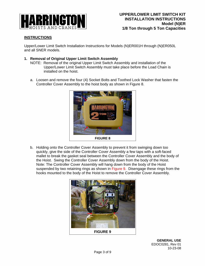
a. Loosen and remove the four (4) Socket Bolts and Toothed Lock Washer that fasten the Controller Cover Assembly to the hoist body as shown in Figure 8.
FIGURE 8
b. Holding onto the Controller Cover Assembly to prevent it from swinging down too
quickly, give the side of the Controller Cover Assembly a few taps with a soft-faced mallet to break the gasket seal between the Controller Cover Assembly and the body of the Hoist. Swing the Controller Cover Assembly down from the body of the Hoist. Note: The Controller Cover Assembly will hang down from the body of the Hoist suspended by two retaining rings as shown in Figure 9. Disengage these rings from the hooks mounted to the body of the Hoist to remove the Controller Cover Assembly.
FIGURE 9
UPPER/LOWER LIMIT SWITCH KIT INSTALLATION INSTRUCTIONS
Model (N)ER1/8 Ton through 5 Ton Capacities
GENERAL USE EDOC0281, Rev 01
10-23-08 Page 4 of 9
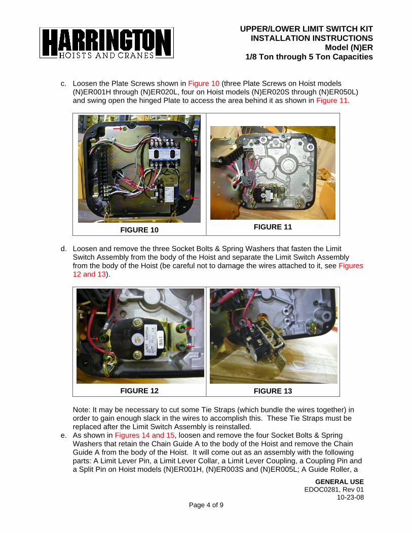
c. Loosen the Plate Screws shown in Figure 10 (three Plate Screws on Hoist models
(N)ER001H through (N)ER020L, four on Hoist models (N)ER020S through (N)ER050L) and swing open the hinged Plate to access the area behind it as shown in Figure 11.
FIGURE 10
FIGURE 11
d. Loosen and remove the three Socket Bolts & Spring Washers that fasten the Limit
Switch Assembly from the body of the Hoist and separate the Limit Switch Assembly from the body of the Hoist (be careful not to damage the wires attached to it, see Figures 12 and 13).
FIGURE 12 FIGURE 13
Note: It may be necessary to cut some Tie Straps (which bundle the wires together) in order to gain enough slack in the wires to accomplish this. These Tie Straps must be replaced after the Limit Switch Assembly is reinstalled.
e. As shown in Figures 14 and 15, loosen and remove the four Socket Bolts & Spring Washers that retain the Chain Guide A to the body of the Hoist and remove the Chain Guide A from the body of the Hoist. It will come out as an assembly with the following parts: A Limit Lever Pin, a Limit Lever Collar, a Limit Lever Coupling, a Coupling Pin and a Split Pin on Hoist models (N)ER001H, (N)ER003S and (N)ER005L; A Guide Roller, a

UPPER/LOWER LIMIT SWITCH KIT INSTALLATION INSTRUCTIONS
Model (N)ER1/8 Ton through 5 Ton Capacities
GENERAL USE EDOC0281, Rev 01
10-23-08 Page 5 of 9
Roller Pin, a Limit Lever Pin, a Limit Lever Collar, a Limit Lever Coupling, a Coupling Pin and a Split Pin on Hoist models (N)ER003H, (N)ER005S and (N)ER010L through (N)ER050L.
FIGURE 14 FIGURE 15
2. Installation of Upper/Lower Limit Switch Assembly
a. Obtain one Chain Guide AL (which should be allocated on the Customer Order) and if applicable, the Guide Roller and Roller Pin currently installed on the removed Chain Guide A as shown in Figure 16. If applicable, reinstall the Guide Roller and Roller Pin onto the Chain Guide AL in the same fashion that they were installed on the Chain Guide A.
FIGURE 16
b. As shown in Figures 17 through 21, remove the Limit Lever Pin, Limit Lever Collar, Limit
Lever Coupling, Coupling Pin and Split Pin (these parts will be removed as an assembly, hereafter referred to as the Limit Lever Coupling Assembly) from the removed Chain Guide A. Obtain one Limit Lever Assembly (which should be allocated on the Customer Order) and align it with the Chain Guide AL. Install the Limit Lever Coupling Assembly onto the Limit Lever Assembly and Chain Guide AL (this assembly consisting of the Chain Guide AL, Limit Lever Assembly, Lever Coupling Assembly, Guide Roller and Roller Pin will hereafter be referred to as the Chain Guide AL Assembly).

UPPER/LOWER LIMIT SWITCH KIT INSTALLATION INSTRUCTIONS
Model (N)ER1/8 Ton through 5 Ton Capacities
GENERAL USE EDOC0281, Rev 01
10-23-08 Page 6 of 9
FIGURE 17 FIGURE 18
FIGURE 19 FIGURE 20
FIGURE 21
c. As shown in Figures 22 through 24, install the Chain Guide AL Assembly onto the body
of the Hoist. Reinstall and tighten the four Socket Bolts & Spring Washers that fasten the Chain Guide AL Assembly to the body of the Hoist (removed in Step 1.e). Make sure the chain remains free of twists, correctly oriented (weld out) and the chain Stopper

UPPER/LOWER LIMIT SWITCH KIT INSTALLATION INSTRUCTIONS
Model (N)ER1/8 Ton through 5 Ton Capacities
GENERAL USE EDOC0281, Rev 01
10-23-08 Page 7 of 9
installed on the correct link. Refer to paragraph 3.2 of the ER or SNER Owner’s Manual for proper placement of Stopper.
FIGURE 22 FIGURE 23
FIGURE 24
d. Prepare two Jumper Wires to connect the existing wires of the Hoist to the Limit Switch Assembly as shown in Figure 25.
FIGURE 25

UPPER/LOWER LIMIT SWITCH KIT INSTALLATION INSTRUCTIONS
Model (N)ER1/8 Ton through 5 Ton Capacities
GENERAL USE EDOC0281, Rev 01
10-23-08 Page 8 of 9
f. Install the two Jumper Wires onto the Limit Switch Assembly as shown in Figures 26 and 27, per the wiring diagram on the inside of the Controller Cover.
FIGURE 26 FIGURE 27
g. As shown in Figures 12 and 13, reinstall the Limit Switch Assembly onto the body of the Hoist, carefully aligning it with the Lever Coupling Assembly. Reinstall and tighten the three Socket Bolts & Spring Washers that fasten the Limit Switch Assembly to the body of the Hoist removed in Step F.1.d.
h. Connect the Jumper Wires installed onto the Limit Switch Assembly to the existing wires of the Hoist as shown in Figures 28 through 30, per the wiring diagram on the inside of the Controller Cover. Note: The Jumper Wire with the female Bullet Connector is installed on terminal “C” and the Jumper Wire with the male Bullet Connector is installed on terminal “D”.
FIGURE 28 FIGURE 29

UPPER/LOWER LIMIT SWITCH KIT INSTALLATION INSTRUCTIONS
Model (N)ER1/8 Ton through 5 Ton Capacities
GENERAL USE EDOC0281, Rev 01
10-23-08 Page 9 of 9
FIGURE 30
i. Operate and continuity-check the Limit Switch Assembly to ensure correct operation. j. Swing the hinged Plate back to its closed position and fasten the Plate Screws loosened
in Step 1.c., being careful not to pinch any wires. k. Reinstall the Controller Cover Assembly onto the body of the Hoist per Figures 8 and 9,
and as follows. 1) Engage the rings of the Controller Cover Assembly with the hooks mounted to the
body of the Hoist. 2) Align the Controller Cover Assembly with the body of the Hoist (there is an alignment
Spring Pin installed in the body of the Hoist which aligns with a hole in the Controller Cover Assembly to facilitate this).
3) Reinstall and tighten the Socket Bolts & Toothed Lock Washers that fasten the Controller Cover Assembly to the body of the Hoist removed in Step 1.a.
Note: As shown in Figure 3-3 in the ER or SNER Owner’s Manual, installation of an Upper/Lower Limit Switch Assembly on Hoist models (N)ER001H through (N)ER015S and SNER003S through SNER010S will require replacing the Cushion Rubbers used on both the load-side and the no-load-side of the Load Chain with Chain Springs (which will be allocated on the Customer Order). Installation of an Upper/Lower Limit Switch Assembly on Hoist models (N)ER020L through (N)ER050L, SNER020L and SNER030C will require replacing the Cushion Rubber used on the no-load-side of the Load Chain with a Chain Spring (which will be allocated on the Customer Order), and omission of the Limit Lever Striker used on the load-side of the Load Chain as it will no longer be required. The load-side Stopper on Hoist models NER030C, (N)ER050L and SNER030C will be located on the 8th link rather than the 6th link from the end. Caution: Upon proceeding to the unit-specific instructions, be sure not to overlook these component changes.
l. After installation has been completed, perform steps outlined in Section 3.6
“Preoperational Checks and Trial Operation” of the ER or SNER Owner’s Manual.