Embed Size (px)
Citation preview


UPPER MISSISSIPPI RIVER RESTORATION ENVIRONMENTAL MANAGEMENT PROGRAM
ENVIRONMENTAL DESIGN HANDBOOK
CHAPTER 6
DREDGING
Point of Contact for Chapter 6 Julie L. Millhollin, P.E. U.S. Army Corps of Engineers, Rock Island District CEMVR-EC-DN Clock Tower Building, P.O. Box 2004 Rock Island, IL 61204 [email protected] 309-794-5439


6-i
UPPER MISSISSIPPI RIVER RESTORATION ENVIRONMENTAL MANAGEMENT PROGRAM
ENVIRONMENTAL DESIGN HANDBOOK
CHAPTER 6
DREDGING
A. RESOURCE PROBLEM AND OPPORTUNITIES ............................................................................... 6-1 B. HABITAT REHABILITATION AND ENHANCEMENT PROJECT (HREP) OBJECTIVES ........ 6-1 1. Hydraulics and Hydrology ..................................................................................................................... 6-2 2. Geomorphology ...................................................................................................................................... 6-2 3. Biogeochemistry ..................................................................................................................................... 6-2 4. Habitat .................................................................................................................................................... 6-2 5. Biota ....................................................................................................................................................... 6-2 C. DREDGING FOR ENVIRONMENTAL RESTORATION .................................................................. 6-5 1. Design Considerations ............................................................................................................................ 6-5 2. Monitoring the Dredge Cuts ................................................................................................................. 6-14 3. Common Problems Associated with Dredging .................................................................................... 6-14 4. Lessons Learned ................................................................................................................................... 6-14 D. DREDGED MATERIAL PLACEMENT & USES IN ENVIRONMENTAL RESTORATION ...... 6-15 1. Design Considerations .......................................................................................................................... 6-15 2. Lessons Learned ................................................................................................................................... 6-16 3. Case Studies ......................................................................................................................................... 6-16 E. REFERENCES ......................................................................................................................................... 6-49 TABLES
6-1 UMRS Ecosystem Restoration Objectives Organized By Essential Ecosystem Characteristics .............. 6-3 6-2 Sedimentation Rates for Various EMP Projects ....................................................................................... 6-6 6-3 Hydraulic Dredge Sizes at Various EMP Projects .................................................................................... 6-9 6-4 Production Rates for Hydraulic Dredges ................................................................................................ 6-12 6-5 Dredge Cut Dimensions for Various EMP Projects ............................................................................... 6-13

Upper Mississippi River Restoration Environmental Management Program
Environmental Design Handbook
Chapter 6
6-ii
FIGURES
6-1 Clamshell Dredge ................................................................................................................................ 6-7 6-2 Cutterhead Pipeline Dredge ................................................................................................................. 6-8 6-3 Browns Lake HREP Site Plan ........................................................................................................... 6-17 6-4 Bertom and McCartney Lakes Dredge Areas – Dredging Plan I ....................................................... 6-19 6-5 Bertom and McCartney Lakes Dredge Area– Dredging Plan II ........................................................ 6-21 6-6 Bertom and McCartney Dredged Material Placement Site ................................................................ 6-22 6-7 Lake Onalaska Dredge Cuts .............................................................................................................. 6-23 6-8 Indian Slough Project Area ................................................................................................................ 6-25 6-9 Potter’s Marsh Site Plan .................................................................................................................... 6-26 6-10 Peoria Lake Enhancement Site .......................................................................................................... 6-29 6-11 Long Island Site Plan ......................................................................................................................... 6-31 6-12 Long Island Channel Dredging Typical Section ................................................................................ 6-32 6-13 Pool 11 Islands ................................................................................................................................... 6-35 6-14 Sunfish Lake Typical Section I .......................................................................................................... 6-36 6-15 Sunfish Lake Typical Section IV ....................................................................................................... 6-37 6-16 Mud Lake Typical Sections A, B, and C ........................................................................................... 6-38 6-17 Mud Lake Typical Sections D, E. and F ............................................................................................ 6-39 6-18 Sediment Trap Plan and Profile ......................................................................................................... 6-40 6-19 Blackhawk Chute/Yankee Chute Plan ............................................................................................... 6-42 6-20 Blackhawk/Yankee Chute typical Section ......................................................................................... 6-43 6-21 Peoria Riverfront Geotextile Containers and Dredging Alignment ................................................... 6-46 6-22 Peoria Riverfront Upper Island Section View Stage II ...................................................................... 6-47 PHOTOGRAPHS
6-1 Clamshell Dredge Side Casting Material at Mud Lake, IA ................................................................. 6-7 6-2 Mechanical Dredging in Quincy Bay Harbor Quincy, IL .................................................................... 6-8 6-3 Hydraulic Dredging Material Discharge at La Grange, MO ............................................................. 6-10 6-4 Floating Excavator ............................................................................................................................. 6-10 6-5 High Solids Geotextile Containers Placement Peoria, IL .................................................................. 6-11 6-6 Bertom and McCartney View of Dredged Material Placement Site From Nearby Bluff, 8/1992 ..... 6-22 6-7 Bertom and McCartney Aerial View of Dredged Channels, 8/1992 ................................................. 6-22 6-8 Bussey Lake Channels ....................................................................................................................... 6-25 6-9 Potter’s Marsh Managed Marshland Beaver Activity........................................................................ 6-27 6-10 Peoria Lake Forested Wetland Management Area ............................................................................ 6-28 6-11 Peoria Lake 2010 Google Earth Aerial Photo .................................................................................... 6-28 6-12 Long Island Small Hydraulic Dredge ................................................................................................ 6-30 6-13 Swan Lake Aerial Layout .................................................................................................................. 6-33 6-14 Blackhawk/Yankee Chute Prior To Dredging ................................................................................... 6-44 6-15 Excavator Used To Dredge Back Channels ....................................................................................... 6-44 6-16 Construction Considerations in a Backwater Area ............................................................................ 6-44 6-17 Peoria Riverfront Island Stage 1 ........................................................................................................ 6-48 6-18 Peoria Riverfront Island Stage II ....................................................................................................... 6-48

6-1
UPPER MISSISSIPPI RIVER RESTORATION ENVIRONMENTAL MANAGEMENT PROGRAM
ENVIRONMENTAL DESIGN HANDBOOK
CHAPTER 6
DREDGING
A. RESOURCE PROBLEM AND OPPORTUNITIES Large river ecosystems support a variety of habitats, of which, backwaters are an integral component. Backwater habitats support many popular sport fishes, waterfowl, shorebirds, and wading birds. Backwaters are also quiet areas off the main channel where people and animals alike can seek refuge. Because of the widespread loss of backwater and secondary channel depth and depth diversity due to the high rates of sediment, fish habitat quality has decreased, especially in the winter when such areas provide refuge from harsh conditions in main channel areas. Many Upper Mississippi River System (UMRS) backwaters have been degraded by excessive amounts of sediment emanating from the basin, tributaries, and mainstem sources. This degradation is in the form of loss of depth, poor sediment quality, poor water quality, and sediment resuspension that blocks light required by aquatic plants. Backwater sedimentation and loss is especially pronounced in lower pools of the Illinois River where sediment from the row crop dominated landscape continues to be excessive. Streambank erosion throughout the basin is another important source of sediment that fills the backwaters. One solution to this degradation problem is backwater dredging. Backwater dredging typically consists of dredging channels with fingers (dredged channels that extend out away from the main dredge cut). The depth and size (length and width) of the dredge cut depends on several site specific factors. The sediment dredged to create depth diversity in the backwaters can be used to enhance aquatic areas with islands or terrestrial areas with increase topographic diversity, which promotes the growth of mast trees. B. HABITAT REHABILITATION AND ENHANCEMENT PROJECT OBJECTIVES Habitat Rehabilitation and Enhancement (HREP) Project features are designed with the intent of meeting specific project objectives. It is important for the design team to have an understanding of the relationship between project features and objectives to help maximum benefits and minimize costs. Also, some of the effects of dredging occur secondarily to the obvious primary effects; understanding these relationships even at a basic level can help inform design decisions.

Upper Mississippi River Restoration Environmental Management Program
Environmental Design Handbook
Chapter 6
6-2
Table 6-1 shows examples of non-specific objectives for HREPs categorized by Essential Ecosystem Characteristics (EECs). For actual projects, these objectives would be more focused, but they are useful here to provide a basic understanding of how project features can be used to meet multiple objectives. The EECs - hydraulics and hydrology, geomorphology, biogeochemistry, habitat, and biota - and some of the objectives that can be addressed with each are briefly discussed. It should be noted that this is not an all-inclusive list, but it is being used here to facilitate consideration of the numerous relationships between features and objectives. 1. Hydraulics and Hydrology. Dredging generally does not directly affect hydrology or hydraulics, other than by increasing the volume of water in the dredged area; however, features such as islands built with dredged material can contribute to this category of objectives indirectly. 2. Geomorphology. Typically the primary purpose for including dredging in HREPs as a stand-alone feature (self-justified) is the restoration of depth in backwaters. Secondarily, the dredged material can be used to improve upland topographic diversity and for the creation of islands. Typically, dredging is included as a means of obtaining material for a dual purpose of island creation and for the restoration of depths in backwaters. Dredging depth is an important considering in meeting HREP objectives. Often, a depth of 6 feet is considered a minimum, but this varies depending on sedimentation rates and target species. 3. Biogeochemistry. Dredging can indirectly affect biogeochemistry by increasing water depths (volume), which in turn can help maintain adequate dissolved oxygen levels especially in winter. The maintenance of oxygenated water below the ice in late winter is a critical consideration. If dredging occurs in highly vegetated areas, the loss of that vegetation would result in some effects to nutrient processing and dissolved oxygen levels, but this is typically of secondary importance. 4. Habitat. Dredging affects habitat directly and indirectly, and is nearly always used in conjunction with a plan to also create or raise islands to meet multiple objectives. The increase in backwater depths, typically to depths of 6 feet or greater, would improve habitat for backwater fishes such as centrarchids and is typically the primary objective for dredging. Dredging in secondary channel can improve habitat for more riverine species, and the dredging of access channel for construction can help meet some side-channel restoration objectives incidentally. However, access dredging and even backwater dredging could be counter-productive if the area dredged contains important habitat/species such as mussels, and such impacts must be considered. 5. Biota. Dredging (and most features used in HREPs) indirectly affect biota through other effects to hydrology, geomorphology, biogeochemistry, and habitat. The effects to biota are seldom measurable in a manner that can clearly prove a cause and effect relationship with project features, so they are often assumed to correlate with physical habitat objectives.

Upper Mississippi River Restoration Environmental Management Program
Environmental Design Handbook
Chapter 6
6-3
Table 6-1. UMRS Ecosystem Restoration Objectives Organized By Essential Ecosystem Characteristics (hydraulics & hydrology, biogeochemistry, geomorphology, habitat, and biota in four floodplain reaches)
Upper Impounded Floodplain Reach Lower Impounded Floodplain Reach Unimpounded Floodplain Reach Illinois River
HYDRAULICS & HYDROLOGY: Manage for a More Natural Hydrologic Regime A more natural stage hydrograph A more natural stage hydrograph
A more natural stage hydrograph
Restored hydraulic connectivity
Restored hydraulic connectivity
Naturalize the hydrologic regime of tributaries
Increase storage & conveyance of flood water on the floodplain
BIOGEOCHEMISTRY: Manage for Processes That Input, Transport, Assimilate, & Output Material Within UMR Basin River Floodplains: e.g., Water Quality, Sediments, & Nutrients Improved water clarity Increased water clarity
Reduced nutrient loading Reduced nutrient loading from tributaries to rivers
Reduced sediment loading from tributaries & sediment resuspension in & loading to backwaters
Reduced sediment loading & sediment resuspension in backwaters
Reduced sediment loading & sediment resuspension in backwaters. NOTE: There are several objectives dealing with tributary loading
Reduced contaminants loading & remobilization of in-place pollutants
Water quality conditions sufficient to support native aquatic biota & designated uses
Water quality conditions sufficient to support aquatic biota
GEOMORPHOLOGY: Manage for Processes That Shape a Physically Diverse & Dynamic River Floodplain System Restore rapids
Restored backwater areas
Restored backwaters
Restored lower tributary valleys
Restore a sediment transport regime so that transport, deposition, & erosion rates & geomorphic patterns are within acceptable limits
Restored bathymetric diversity, & flow variability in secondary channels, islands, sand bars, shoals & mudflats
Restored bathymetric diversity, & flow variability in secondary channels, islands, sand bars, shoals & mudflats Restored secondary channels & islands
Restored floodplain topographic diversity
Restored lateral hydraulic connectivity

Upper Mississippi River Restoration Environmental Management Program
Environmental Design Handbook
Chapter 6
6-4
Table 6-1. UMRS Ecosystem Restoration Objectives Organized By Essential Ecosystem Characteristics (hydraulics & hydrology, biogeochemistry, geomorphology, habitat, and biota in four floodplain reaches)
Upper Impounded Floodplain Reach Lower Impounded Floodplain Reach Unimpounded Floodplain Reach Illinois River
HABITAT: Manage for a Diverse & Dynamic Pattern of Habitats to Support Native Biota Restored habitat connectivity Restored habitat connectivity
Restored habitat connectivity
Restored riparian habitat Restored riparian habitat Restored riparian habitat
Restored aquatic off-channel areas
Increase the extent & number of sand bars, mud flats, gravel bars, islands, & side channels towards a more historic abundance & distribution.
Restored terrestrial floodplain areas Restored channel areas
Diverse & abundant native aquatic vegetation communities (SAV, EAV, RFV)
Restored large contiguous patches of native plant communities to provide a corridor along the UMR Restored floodplain areas
Restored floodplain wetland areas
Restored degraded & rare native habitats
Restored lower tributary valleys
BIOTA: Manage for Viable Populations of Native Species Within Diverse Plant & Animal Communities
Diverse & abundant native aquatic vegetation communities (SAV, EAV, R/F)
Diverse & abundant native floodplain forest & prairie communities
Diverse & abundant native fish community
Diverse & abundant native fish community Diverse & abundant native mussel community
Diverse & abundant native bird community
Restored diversity & extent of native communities throughout their range in the UMRS
Viable populations of native species throughout their range in the UMRS at levels of abundance in keeping with their biotic potential
Viable populations of native species throughout their range in the UMRS at levels of abundance in keeping with their biotic potential
Reduced adverse effects of invasive species Reduced adverse effects of invasive species
Restored diversity & extent of native communities throughout their range in the UMRS
Upper Mississippi River Restoration Environmental Management Program
Environmental Design Handbook
Chapter 6
6-5
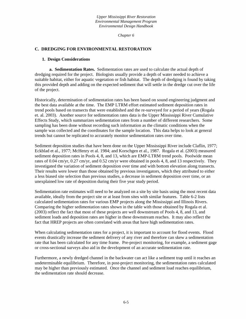
C. DREDGING FOR ENVIRONMENTAL RESTORATION 1. Design Considerations a. Sedimentation Rates. Sedimentation rates are used to calculate the actual depth of dredging required for the project. Biologists usually provide a depth of water needed to achieve a suitable habitat, either for aquatic vegetation or fish habitat. The depth of dredging is found by taking this provided depth and adding on the expected sediment that will settle in the dredge cut over the life of the project. Historically, determination of sedimentation rates has been based on sound engineering judgment and the best data available at the time. The EMP LTRM effort estimated sediment deposition rates in trend pools based on transects that were established and the re-surveyed for a period of years (Rogala et. al. 2003). Another source for sedimentation rates data is the Upper Mississippi River Cumulative Effects Study, which summarizes sedimentation rates from a number of different researchers. Some sampling has been done without recording such information as the climatic conditions when the sample was collected and the coordinates for the sample location. This data helps to look at general trends but cannot be replicated to accurately monitor sedimentation rates over time. Sediment deposition studies that have been done on the Upper Mississippi River include Claflin, 1977; Eckblad et al., 1977; McHenry et al. 1984; and Korschgen et al., 1987. Rogala et al. (2003) measured sediment deposition rates in Pools 4, 8, and 13, which are EMP-LTRM trend pools. Poolwide mean rates of 0.04 cm/yr, 0.27 cm/yr, and 0.52 cm/yr were obtained in pools 4, 8, and 13 respectively. They investigated the variation of sediment deposition over time and with bottom elevation along transects. Their results were lower than those obtained by previous investigators, which they attributed to either a less biased site selection than previous studies, a decrease in sediment deposition over time, or an unexplained low rate of deposition during their five year study period. Sedimentation rate estimates will need to be analyzed on a site by site basis using the most recent data available, ideally from the project site or at least from sites with similar features. Table 6-2 lists calculated sedimentation rates for various EMP projects along the Mississippi and Illinois Rivers. Comparing the higher sedimentation rates shown in the table with those obtained by Rogala et al. (2003) reflect the fact that most of these projects are well downstream of Pools 4, 8, and 13, and sediment loads and deposition rates are higher in these downstream reaches. It may also reflect the fact that HREP projects are often correlated with areas that have high sedimentation rates. When calculating sedimentation rates for a project, it is important to account for flood events. Flood events drastically increase the sediment delivery of any river and therefore can skew a sedimentation rate that has been calculated for any time frame. Pre-project monitoring, for example, a sediment gage or cross-sectional surveys also aid in the development of an accurate sedimentation rate. Furthermore, a newly dredged channel in the backwater can act like a sediment trap until it reaches an undeterminable equilibrium. Therefore, in post-project monitoring, the sedimentation rates calculated may be higher than previously estimated. Once the channel and sediment load reaches equilibrium, the sedimentation rate should decrease.

Upper Mississippi River Restoration Environmental Management Program
Environmental Design Handbook
Chapter 6
6-6
Table 6-2. Sedimentation Rates for Various EMP Projects on the Mississippi River
Site River Mile Years From Which Avg Rate Was Determined
Avg Sedimentation Rate (DPR) (in/yr) 1
Date Project Completed
Andalusia 463.0-462.0 1936-1987 0.50 09-1994 Bertom McCartney Lakes 602.8-599.0 1938-1988 0.39 10-1991 Big Timber 445.0-443.0 1938-1988 0.51 10-1994 Brown’s Lake 546.0-544.0 1930-1987 0.45 09-1990 Cottonwood Island 331.0-328.5 1938-1994 0.46 05-2000 Lake Odessa 434.5-441.5 1950-1995 .39-.79 Long Island (Gardner) Div 340.2-332.5 N/A 0.21 09-2004 Lake Onalaska 702.5-704.0 1937-1986 0.35 10-1989 Bussey Lake 616.2-617.2 1935- 1987 0.31 06-1996 Indian Slough 760 - 758 Not available Peoria Lake 181.0-162.0 N/A 1.5 10-1996
Pool 11 Islands 592.0-583.0 1938-1950 1951-1995
0.61 0.13 07-2005
Potters Marsh 526.0-522.5 1938-1990 0.25 12-1995 1 DPR - Definite Project Report, a planning document for EMP projects b. Dredge Method. There are two basic categories of dredges, mechanical and hydraulic. Both types of dredges are designed to maximize the quantity of material dredged. While selecting dredge equipment for a project, it should be noted that most dredges are not well suited to efficiently work within small tolerances such as ± 0.1 feet in elevation or in maintaining very specific side slopes. In addition to mechanical and hydraulic dredges, there are many more sub-types of dredge equipment and dredging techniques. A sub-type of dredge equipment discussed in this chapter is the floating excavator. A floating excavator is ideal for use in marsh-like areas. A more recent dredging technique that is being more widely used is high solids dredging such as Dry DREdge™. This technique can be used for the filling of geotubes or for any type of dredging where there are water quality concerns. i. Mechanical Dredging. Mechanical dredges typically include backhoe, clamshell, and dragline. Figure 6-1 shows a schematic of a mechanical dredge as well as a picture of a clamshell bucket.

Upper Mississippi River Restoration Environmental Management Program
Environmental Design Handbook
Chapter 6
6-7
Figure 6-1. Clamshell Dredge
Mechanical dredges are capable of dredging hard packed material and also have the ability to remove debris. For the most part, these type of dredges can work in relatively tight areas and are efficient for side casting material from dredge cut to placement site. Photograph 6-1 shows a clamshell dredge side casting material during the construction of Mud Lake, part of the Pool 11 Islands EMP project. Mechanical dredges are also efficient for transporting material over long haul distances (greater than two miles) and have relatively low mobilization costs. As compared with hydraulic dredging, mechanical dredging does not have the issue of managing return water.
Photograph 6-1. Clamshell Dredge Side Casting Material at Mud Lake, IA
Mechanical dredging generally has lower production rates when compared to hydraulic dredging. It is also difficult to retain fine/loose material in conventional buckets. Mechanical dredging is also inefficient for transporting material over short haul distances (less than two miles), and in areas which

Upper Mississippi River Restoration Environmental Management Program
Environmental Design Handbook
Chapter 6
6-8
contain restricted width access points when barges are used to transport the dredged material. For mechanical dredging in Quincy, IL, barges were used to transport dredged material to the disposal site (photograph 6-2).
Photograph 6-2. Mechanical Dredging in Quincy Bay Harbor Quincy, IL
ii. Hydraulic Dredging. Hydraulic dredges include cutterhead pipeline, hopper, suction, and dustpan. For ecosystem dredging, the hopper, suction and dustpan dredges have not been typically viable options due to their size and difficulty in maneuvering, although they could be used for some large side channel work or island construction efforts. Therefore, this section will focus on the cutterhead pipeline dredge. Figure 6-2 is a schematic of a cutterhead pipeline dredge as well as a picture of the cutterhead. A cutterhead pipeline dredge is shown on the cover of this chapter.
Figure 6-2. Cutterhead Pipeline Dredge

Upper Mississippi River Restoration Environmental Management Program
Environmental Design Handbook
Chapter 6
6-9
Cutterhead pipeline dredges are sized based on the discharge pipe inside diameter and are typically available from 8-inch to 20-inch with larger applications reaching 36-inches or more. Table 6-3 shows the various EMP projects that have used hydraulic dredging in their construction. Cutterhead pipeline dredges are capable of excavating most types of material and can even dredge some rock without blasting. Unlike mechanical dredging, hydraulic dredging allows for direct placement of material into a placement site. Hydraulic dredging also allows for the ability to pump almost continuously which results in higher production rates than mechanical dredging. This method is also very cost effective if within economical pumping distances of placement site (less than 2 miles). Cutterhead pipeline dredges, however, have difficulty with coarse sand in high currents. In general, these types of dredges are sensitive to strong currents. Therefore, provisions should be made in the plans and specifications of any project to allow for down time for dredging in case of flood events. Another provision to put in the specifications is the passage of other motor vessels as the pipelines and/or wires associated with hydraulic dredging may obstruct navigation. Other disadvantages of this type of hydraulic dredging are that cohesive material and debris can block cutterhead which can in turn reduce efficiency. The dredging slurry is 80 to 90 percent water (the other 10 to 20 percent is sediment) which can cause difficulties in obtaining and administering a water quality permit. Since this water has to be returned back to the source, return water management must be incorporated into any design. A minimum of a 5-acre site is recommended for hydraulic dredging in order to settlement of suspended solids from the slurry and leave sufficient room for the stockpiling of material. Photograph 6-3 shows a hydraulic dredging discharge site at the Union Township Levee and Drainage District near La Grange, MO. Lastly, hydraulic dredging also has high mobilization costs when compared to mechanical dredging.
Table 6-3. Hydraulic Dredge Sizes at Various EMP Projects on the Mississippi River
Project River Mile Dredge Quantity
(cubic yards) Size of
Cutterhead (in.) Bertom McCartney Lakes 602.8-599.0 400,000 16 Lake Odessa 434.5-441.5 Lake Onalaska 704-702.5 1,340,000 22 Bussey Lake 617-616 270,000 24 Indian Slough 760-758 46,000 12 Long Island (Gardner) Division 340.2-332.5 83,000 8 Big Timber 445.0-443.0 143,000 8-10 Spring Lake 532-536 22 Brown’s Lake 546.0-544.0 370,000 10-14

Upper Mississippi River Restoration Environmental Management Program
Environmental Design Handbook
Chapter 6
6-10
Photograph 6-3. Hydraulic Dredging Material Discharge at La Grange, MO
iii. Floating Excavator. A floating excavator as seen in photograph 6-4 below is a normal hydraulic excavator with a different undercarriage that gives the excavator a very low ground pressure. This very low ground pressure allows the excavator to work in marsh/wetland type environments where a normal excavator or typical dredge cannot reach.
Photograph 6-4. Floating Excavator
As stated previously, floating excavators are ideal for those hard to reach places and are highly mobile. However, they are not as efficient as the other types of machines discussed earlier in this chapter.

Upper Mississippi River Restoration Environmental Management Program
Environmental Design Handbook
Chapter 6
6-11
iv. High Solids Dredging. High solids dredging, also known as Dry DREdge™, is a very useful technique. This technique utilizes mechanical dredging to produce a slurry that is 50 to 80 percent solids, thus resulting in a relatively clean effluent. This technique can be used to fill geotextile containers, which can in turn be used to build form the outer ring of an island. Photograph 6-5 depicts the construction of an island in the Illinois Waterway near Peoria, IL using geotextile containers. High solids dredging is one of the only techniques suitable for building islands out of a highly silty material. This technique can be used when contaminants are present in the sediment.
Photograph 6-5. High Solids Geotextile Containers Placement Peoria, IL
c. Production Rates. Production rates are the amount of material, usually measured in cubic yards (CY), a dredge can remove per unit of time, usually expressed per hour. Production rates are useful to help determine the construction schedule of a project. Production rate estimates should be one of the basic components in determining the length of a construction contract.
When estimating the production rate, research should be done so that the production rate accurately depicts what will occur in the field. The Cost Engineering Dredge Estimating Program is available online from the Walla Walla District at http://www.nww.usace.army.mil/html/offices/ed/c/cedep.asp . The Microsoft Excel spreadsheet allows the user to estimate construction costs, mobilization costs, and production rates based upon variable factors at individual dredging sites using rock pipeline, pipeline, mechanical, and hopper dredging techniques. Table 6-4 lists an estimated production rates for hydraulic dredging.

Upper Mississippi River Restoration Environmental Management Program
Environmental Design Handbook
Chapter 6
6-12
Table 6-4. Production Rates for Hydraulic Dredges
Dredge Size
Assumed Pump Power
Up to This Length 1
Hourly Production
At This Length 1
Hourly Production
10 in 500 HP 2,000 ft 200 cy/hr 4,000 ft 130 cy/hr 12 in 700 HP 2,500 ft 270 cy/hr 5,000 ft 180 cy/hr 14 in 1000 HP 3,000 ft 380 cy/hr 6,000 ft 250 cy/hr 16 in 1300 HP 3,500 ft 500 cy/hr 7,000 ft 330 cy/hr 18 in 1600 HP 4,000 ft 650 cy/hr 8,000 ft 420 cy/hr 20 in 2000 HP 4,000 ft 800 cy/hr 8,000 ft 520 cy/hr 24 in 3000 HP 5,000 ft 1,200 cy/hr 10,000 ft 780 cy/hr 27 in 4000 HP 5,500 ft 1,500 cy/hr 11,000 ft 980 cy/hr 30 in 5200 HP 6,000 ft 1,800 cy/hr 12,000 ft 1,170 cy/hr 32 in 6700 HP 6,000 ft 2,100 cy/hr 12,000 ft 1,370 cy/hr
1 The pipe length consists of the actual length of pipe from the dredge to the discharge point, plus an equivalent length to allow for the piping on the dredge, for fittings, and for rises in elevation.
d. Dredge Cut Dimensions. Dredge cuts for environmental restoration are very site specific. There are several factors that should be taken into consideration when designing a channel. Some factors are biological concerns, logistics of dredge equipment mobilization, and hydrology and hydraulics. Determination of the desired dredging depth includes assessment of typical water level elevations, present low-flow winter regulations, desired maintained water depth and projected sedimentation over the project life. Typically, the maintained water depth is determined from the anticipated maximum ice depth and the desired maintained water depth below that ice. Ice depths vary along the Upper Mississippi River, and need to be determined for the proposed HREP location. A desired water depth of 2 to 4 feet below the ice is typically optimal. This translates to a maintained water depth in the four to 6-foot range with 6 feet being a commonly accepted depth. It should be noted however that flow conditions can alter the formation of ice, for example, higher flows does not allow the water to freeze; therefore, a hydraulic analysis should be done to determine what flows will be present and if that flow will allow ice to form. Caution should be used to avoid dredging to elevations greater than those required to establish the maintained water depth as this could result in the loss of littoral habitat. Width of the dredge cut will be determined by existing channel conditions, project requirements, placement site capacity, and project funding. Typically, dredge cuts are designed based on a bottom width. Table 6-5 lists various dredge cut dimensions for various EMP projects. In-depth geotechnical analysis needs to be performed to determine the type of material that is being dredged so that the proper side slopes can be designed. In some cases, the channel has been dredged with vertical side slopes, and the material is allowed to slough to its natural angle of repose. This helps to minimize the project cost by reducing actual dredging time and quantities.

Upper Mississippi River Restoration Environmental Management Program
Environmental Design Handbook
Chapter 6
6-13
Table 6-5. Dredge Cut Dimensions for Various EMP Projects on the Mississippi River
Project River Mile
Bottom Width (ft)
Depth Below Flat Pool (ft)
Channel Side Slopes (H:V)
Andalusia 463.0-462.0 2:1 Cottonwood 331.0-328.5 Vertical
Lake Odessa 434.5-441.5 30 30 50
6 6 6
1.5:1 4:1 4:1
Lake Onalaska 704-702.5 100-150 8-15 2:1 3:1
Bussey Lake 617-616 75 6-8 6:1 Indian Slough 760-758 125 5 Ang. Repose Long Island (Gardner) Division 340.2-332.5 50 7.5 Vertical Peoria Lake 178.5-181.0 95 7 4:1 & 3:1 Potter’s Marsh 526.0-522.5 50 8-10 2:1 Big Timber 445.0-443.0 30-50 4-9 2:1 Brown’s Lake 546.0-544.0 30 9 2:1 Pool 11 Islands 592.0-583.0 33 8 3:1
e. Deep Holes. Deep holes are dredged “pockets” of deeper water that provide habitat for fish. Deep holes are typically dredged to a depth of 20 feet below the flat pool elevation and vary greatly in size. Either a mechanical or hydraulic dredge can be used to construct a deep hole, depending on the size. For smaller deep holes, a mechanical dredge should be used as it will be difficult to maneuver the cutterhead on a hydraulic dredge. Special attention should be paid to the sedimentation rates in the area of the deep hole as these cuts have more of a tendency to act like sediment traps. f. Sediment Basins. A sediment basin consists of an earth embankment or a combination ridge and channel generally constructed across the slope and minor watercourse to form a sediment trap and a water detention basin. Sediment traps can be used to reduce watercourse and gully erosion, trap sediment, reduce and manage onsite and downstream runoff, and improve downstream water quality. While not expressly precluded under the EMP authorization, Corps policy has generally regarded such features (upland sediment control) as beyond its purview and as the responsibility of other agencies. Nevertheless, two HREPs with upland features, Swan Lake and Batchtown, have been advanced as a result of specific Congressional directives. In both instances, the upland sediment control features were the most cost-effective way of protecting habitat in the project area. These features include hillside retention ponds, terracing, and other measures to reduce sediment delivery to the specific project area, but do not extend to land conservation practices throughout the watershed. Not all sediment basins are constructed in the upland, and could be constructed within floodplains for the purposes of ecosystem restoration. The Natural Resources Conservation Service (NRCS) has expertise in designing sediment basins, developed through years of helping farmers and landowners to reduce erosion of their land. The NRCS has published two Conservation Practice Standard documents (Codes 350 and 638, 2001) on the design of sediment basins that should be considered during the design of a sediment basin; site

Upper Mississippi River Restoration Environmental Management Program
Environmental Design Handbook
Chapter 6
6-14
specific requirements or project features could be modified based on the site and desired goals for the project. 2. Monitoring the Dredge Cuts. Monitoring of the dredge cuts should start as soon as they are constructed. Monitoring this soon will aid in the determination of the sedimentation rates for the new dredge cut. To maintain consistency, survey monumentation should be coordinated with any individual who could monitor the project. These individuals could include surveyors, hydrologists, fish biologists, etc. The survey monuments should be positioned such that they will be easily used and not deteriorate through the life of the project. 3. Common Problems Associated with Dredging. Most difficulties in dredging do not shut the operation down for long periods of time. The most common problem associated with hydraulic dredging is damaging the cutterhead. Another problem is access into backwater sites. Most problems, except for equipment failures, can be avoided by obtaining as much information about the bathymetry and hydraulics of the site and providing that in the plans and specifications that the contractor will utilize to construct the project.
4. Lessons Learned
• Document assumptions made about production rates estimated during the planning and plans and specifications phase of a project. This documentation will help evaluate a contractor’s proposal to construct the project. Also, document the contractor’s actual production rate to add to record for future reference.
• Always keep in mind the water quality restrictions on return water. This can drastically alter the method of sediment removal.
• Make sure the contractor is aware of the flooding frequency of the area.
• Layout the schedule of the project such that the likelihood of the contractor mobilizing twice is minimal.
• Dredging is very site specific – each reach of any river has its own characteristics that need to be studied and monitored to achieve a lasting design.
• Estimating the sedimentation rate during planning and plans and specifications phases is vital to the success of the project. If the sedimentation rate is significantly inaccurate, the project may have to be dredged midway through the life of the project at the sponsor’s expense.
• Based on material characteristics, if sloughing is anticipated the dredge cut should be widened or stepped to minimize depth and loss as cut sloughs in.
• Inlet channels that are directly perpendicular to the flow path of the main channel typically silt in faster than an inlet channel that is not.
• The use of flexible dredge disposal pipe, most commonly in the form of high density polyethylene, is may be preferred in sites where disturbance to existing conditions must be limited. The pipe is flexible enough to bend and avoid trees and is light enough to be pulled by a single dozer or skid steer.

Upper Mississippi River Restoration Environmental Management Program
Environmental Design Handbook
Chapter 6
6-15
D. DREDGED MATERIAL PLACEMENT AND USES IN ENVIRONMENTAL RESTORATION 1. Design Considerations. Placement sites for dredged material may be located upland out of the floodway, along the bankline or inwater. They may be confined disposal facilities (CDF) incorporating perimeter berms to confine the dredged material and return water, if applicable, or open sites allowing easy access for placement sites and shaping of the dredged material. A list of potential placement sites that meet project goals and objectives should be developed for evaluation. Over the years, more efficient and worthwhile uses of dredged material, rather than just storing it on the bankline or in a CDF, have been developed. This trend has greatly impacted the use of dredge material in environmental restoration. Dredged material is now used to build islands, seed islands, build low level of protection levees, and create floodplain depth diversity. a. Conventional Placement of Dredged Material. Once a list of potential placement sites has been developed, a search of existing databases, maps and other sources should be completed to identify any known issues or concerns. Some possible issues or concerns are:
• impacts to wetlands, endangered species, water quality, aquatic and terrestrial species • floodway conveyance, flood heights, and flood storage impacts • existing land uses • real estate issues • hazardous, toxic, and radioactive waste concerns • beneficial uses
b. Restoration Uses for Dredged Material
i. Islands. The main restoration use for dredge material is for island building. This is a very beneficial use because the haul distance from the dredge cut to the island site is usually very minimal. Islands are constructed using both hydraulic and mechanical dredges with material transported from various distances. The longest distances can exceed several miles and involve the use of a booster pumps if being done hydraulically. The shortest distances involve side casting material to build the island. Refer to Chapter 9 of this handbook for more information on island building. ii. Levee. Dredged material can also be used to build a new levee or strengthen an existing levee as part of a moist soil unit. Attention needs to be paid to the type of material being dredged so that the proper side slopes and compaction requirements are met. This will help ensure stability of the structure. Refer to Chapter 2 of this handbook for more information on levees and moist soil units. iii. Floodplain Depth Diversity. Dredged material can be placed in a variety of places to increase floodplain depth diversity and habitat. Dredged material can be placed on existing islands, banklines, and uplands. These areas are typically planted with mast trees. Refer to Chapter 8 of this handbook for more information on floodplain restoration.

Upper Mississippi River Restoration Environmental Management Program
Environmental Design Handbook
Chapter 6
6-16
2. Lessons Learned
• The sediment to be dredged should be thoroughly tested for contaminants. If the tests results show an unacceptable level of contaminants in the sediment, an environmental engineer should be consulted. Presence of contaminants in sediment can severely limit what can be done with that sediment.
• Typical permits required for dredging and dredged material placement include NEPA, CWA section 404(b)(1) compliance, state floodplain permit, section 401 water quality certifications and if applicable, a state floodplain construction permit and CDF permit
• When placing dredged material in and around mature trees, the depth of the material should be minimized so as to not kill the trees
E. Case Studies 1. CHIPPEWA RIVER SEDIMENT TRAP St. Paul District, Mississippi River (RM 763.4) Feature Constructed 1984
At the confluence of the Chippewa and Mississippi Rivers, a sediment trap has been maintained by the St. Paul District since 1984. Dredging of the trap averages 120,000 tons per year with the remaining 820,000 tons per year entering the Mississippi River. The contribution of bed material sediment from this tributary is one of the primary reasons 1/3 of the St. Paul District’s dredging occurs in Lower Pool 4. Bed and bank erosion accounts for the majority of the sediment being transported. Lessons Learned
• Because sediment traps tend to trap more sediment than the navigation channel, the overall dredging volumes in this reach of the river have increased since 1984. However, dredging of the trap resulted in significant decreases in dredging at the downstream Reads Landing and Crats Island dredge cuts (76 percent and 26 percent respectively). The reduction in dredging at Reads Landing has significance beyond the amount of material dredged. Prior to 1984, channel closures and emergency dredging were common occurrences at Reads Landing. This resulted in significant delays to the towing industry and environmental concerns regarding the emergency placement of the dredged material. This has been mostly eliminated through maintenance of the sediment trap.
• Although the Chippewa River sediment trap is maintained using O&M funds, it definitely reduces downstream sediment loads. Since sediment deposition is a major concern on the Mississippi River, the benefits the trap has in reducing the downstream sediment load and subsequent sediment transport to backwater areas is a positive impact. Sediment traps such as this could be considered at other tributaries.

Upper Mississippi River Restoration Environmental Management Program
Environmental Design Handbook
Chapter 6
6-17
2. BROWN’S LAKE HREP (figure 6-3) Rock Island District, Mississippi River (RM 546.0-544.0) Contract Number DACW25-88-C-0077 Feature Constructed 1988-1990
• Included construction of deflection levee, a water control structure, improved inlet side channel, side channel excavation, lake dredging, terrestrial dredged material placement, and planting of mast trees (figure 6-3)
• Dredging component included the inlet channel improvement to reorient the mouth downstream to minimize debris and bedload sediment from reaching the new water control structure.
• Performed lake dredging to maintain a minimum water depth of 5 feet below flat pool elevation. 20-foot holes were dredged for diversity.
• Placement site was replanted with mast tree.
Performance. The dredged channels and deeps holes appeared to be filling in at a faster rate than the undisturbed area. Further data collection will continue to define sedimentation rates.
Figure 6-3. Browns Lake HREP Site Plan

Upper Mississippi River Restoration Environmental Management Program
Environmental Design Handbook
Chapter 6
6-18
3. BERTOM AND MCCARTNEY LAKES Rock Island District Mississippi River (RM 602.8-599.0) Contract Number DACW25-90-C-0020 Feature Constructed 1990-1991
• Incorporated a partial closing structure, fish and mussel rock habitat, and dredging to meet project objectives. Dredging features included deep water habitat, an increase in dissolved oxygen, and a minimum water depth of 6 feet over the project life, with a 10-foot minimum depth adjacent to the railroad tracks (figures 6-4 and 6-5 and photograph 6-7).
• Dredged material was used to build a kidney shaped island with a perched wetland. The island has significant waterfowl use (figure 6-6 and photograph 6-6).
Performance. Currently, the project is meeting its goal of providing deep aquatic habitat volume, but the rate of loss of aquatic habitat volume due to sediment deposition appears to be larger than anticipated based on sediment transects collected in 1993 and 1998. The rate of volume loss has been 3.9 ac-ft/yr versus 1 ac-ft/yr.

Upper Mississippi River Restoration Environmental Management Program
Environmental Design Handbook
Chapter 6
6-19
Figure 6-4. Bertom and McCartney Lakes Dredge Areas – Dredging Plan I

Upper Mississippi River Restoration Environmental Management Program
Environmental Design Handbook
Chapter 6
6-20
Figure 6-5. Bertom and McCartney Lakes Dredge Area -Dredging Plan II

Upper Mississippi River Restoration Environmental Management Program
Environmental Design Handbook
Chapter 6
6-21
Figure 6-6. Bertom and McCartney Dredged Material Placement Site

Upper Mississippi River Restoration Environmental Management Program
Environmental Design Handbook
Chapter 6
6-22
Photograph 6-6. Bertom and McCartney View of Dredged Material Placement Site From Nearby Bluff, 8/1992
Photograph 6-7. Bertom and McCartney Aerial View of Dredged Channels, 8/1992

Upper Mississippi River Restoration Environmental Management Program
Environmental Design Handbook
Chapter 6
6-23
4. LAKE ONALASKA HREP St. Paul District, Mississippi River (RM 704 – 702.5) Feature Constructed 1989
• Each channel leg is approximately 7,000 feet long and 100 to 150 feet wide, although some parts of the channels were dredged up to 300 feet wide to gain additional material for highway fill. The majority of the channel bottom was excavated to a depth between 10 and 15 feet, except the lower 1,500 feet of each channel, which was dredged to a depth of 8 to 10 feet (at the low control pool elevation of 639 feet above mean sea level). Greater depths were excavated in a spur that extends toward Halfway Creek, creating a sediment basin at the mouth of the creek (figure 6-7). Additional channels were dredged adjacent to and between the habitat channels in order to supply the additional amount of material required for the Wisconsin DOT highway project. These channels are not considered to be part of the habitat project; however, they do provide increased deepwater habitat benefits to this backwater area.
• Approximately 1,340,000 cy of material was dredged from the channel areas (160,000 cy for islands, 900,000 cy for highway embankment, and 280,000 cy of overburden fine material placed on Rosebud Island). The project was designed with sufficient dredged depths to preclude maintenance dredging during its 50-year life (USACE 1998).
Lessons Learned
• Dredge production was reduced with coarse gravel size alluvium encountered in the dredge cuts.
• Project objectives should include information on the range of variation of important parameters. In this case the dredge cuts were deep enough, but the current velocity was too high in the winter. This was eventually solved by changing the operation of a downstream dam to reduce flow through the dredge cuts in the winter.
• Secondary benefits/innovation (i.e. the terrestrial habitat on the islands and dredge material placement sites) is important.
Figure 6-7. Lake Onalaska Dredge Cuts

Upper Mississippi River Restoration Environmental Management Program
Environmental Design Handbook
Chapter 6
6-24
5. INDIAN SLOUGH HREP St. Paul District, Mississippi River (RM 760.0 – 758.0)) Feature Constructed 1993
• Dredging in Big Lake (figure 6-8) was done to increase water depths in a shallow area that historically provided good winter habitat for fish. Approximately 46,000 cy of fine material dredged from Big Lake Bay was used to cap 10 acres of dredged material in the Crats Island placement site. The area and depth of dredging in Big Lake Bay were sized to match the available placement site capacity and to tie the dredged area into the deeper portions of Big Lake. The restoration of water depths consisted of deepening approximately 11 acres of Big Lake by about 2.5 feet. The dredged channel in Big Lake Bay was approximately 3,000 feet long with a bottom width of 125 feet and depth of 5 feet.
• The two areas where the fine-grained dredged material was placed on Crats Island were seeded in May 1994 (Anfang 1995). Burr oak tree seedlings were also planted on the site.
Figure 6-8. Indian Slough Project Area

Upper Mississippi River Restoration Environmental Management Program
Environmental Design Handbook
Chapter 6
6-25
6. BUSSEY LAKE HREP St. Paul District, Mississippi River (RM 616.5-617.5) Contract Number DACW37-92-0015 and DACW37-95-C-0024 Feature Constructed 1992-1996
• Stage 1 included dredging 12,000 linear feet of channel (photograph 6-8) in the lake to rehabilitate fish habitat. The channels had 75-foot bottom widths with 1 vertical to 6 horizontal side slopes. The majority of the channels were dredged to a depth of 8 feet. In a few locations, channels were dredged to 6 and 7 feet deep to create more bathymetric diversity while minimizing dredging volumes.
• Half the dredged material was placed at the Guttenberg Waterfowl Ponds project to create and additional moist soil unit and to improve operability of the existing ponds. The rest was placed at the Willow Island placement site just downstream of Bussey Lake
• Stage 2 installed a gate on an existing culvert to control flow from Buck Creek into the north end of Bussey Lake. Deepening 29 acres of Bussey Lake expanded available fish habitat, and gated structure reduced sediment transport into the lake.
Lessons Learned
• Verify elevations of the dredge cuts to create different depths and vary habitat
• Add artificial bottom structure to dredge cuts to improve fish habitat
• Consider constructability along with habitat values when designing dredge cuts to maximize efficiency; i.e., habitat gain per unit of cost.
• Dredge production reduced with coarse material.
• Secondary benefits/innovation is important
Photograph 6-8. Bussey Lake Channels

Upper Mississippi River Restoration Environmental Management Program
Environmental Design Handbook
Chapter 6
6-26
7. POTTER’S MARSH POOL EMP Rock Island District, Mississippi River (RM 526.0-522.5) Contract Number: DACW25-93-C-0115 Feature Constructed: 1993-1996
• Included construction of a sediment trap, dredging was done in the upper/lower sloughs and embayment areas creating both shallow and deep water habitat, pothole excavation, and construction of a managed marshland (figure 6-9).
Figure 6-9. Potter’s Marsh Site Plan
• Dredged material was placed in a confined disposal site located in an area of secondary growth adjacent to Central Island. The location and shape of the placement site were defined so as to not inundate the lower lying marshland areas downstream and to the east as well as the heavy timber and natural potholes to the north.
• Column settling analyses were performed to determine the required detention time and total for initial dredged material containment. The dredged material needed about 25 hours of settling time and required an initial volume of approximately 1.75 times larger than the in situ sediments. Based on these analyses the interior area of the placement site needed to be 35.5 acres with a perimeter dike 14 feet high.
• The dredged material was placed to an initial depth of 12 feet, settling to a depth of 8 to 10 feet after the first year. At that time, the perimeter dike upper surface was lowered to approximately 2 to 3 feet above the dredged material.

Upper Mississippi River Restoration Environmental Management Program
Environmental Design Handbook
Chapter 6
6-27
• After settlement of the dredged material, an approximate 32.5-acre marshland was constructed on the confined placement site (photograph 6-9).
Photograph 6-9. Potter’s Marsh Managed Marshland Beaver Activity
8. PEORIA LAKE HREP Rock Island District, Illinois Waterway (RM 181.0-162.0) Solicitation Number DACW25-93-B-0035 Feature Constructed 1993-1997
• Included construction of a forested wetland management area (photograph 6-10), a barrier island, and restoration of a flowing side channel (figure 6-10).
• The barrier island (photograph 6-11) was constructed using mechanically dredged soft sediments with gentle placement on the adjacent site using multiple passes for island stability. A minimum 7 CY clamshell bucket was included in the dredging scope. This requirement slightly increased the mobilization costs (the contractor was from Louisiana) but it drastically reduced the per unit cost of dredging the material. A clamshell bucket was selected because it can excavate large soil masses without significantly disturbing the internal strength of the soil and it produces the least turbidity compared to dragline or backhoe buckets. This type of dredging was selected due to its cost effectiveness and maximization of soft sediment placed on the island that promotes re-establishment of vegetation for habitat enhancement.
Performance: Overall the project is performing reasonably well. The barrier island has been stable and is providing a wind break, although the overburden island has deteriorated. The forested wetland management area has provided usable water fowl habitat and the East River Channel is still open.

Upper Mississippi River Restoration Environmental Management Program
Environmental Design Handbook
Chapter 6
6-28
Photograph 6-10. Peoria Lake Forested Wetland Management Area
Photograph 6-11. Peoria Lake 2010 Google Earth Aerial Photo

Upper Mississippi River Restoration Environmental Management Program
Environmental Design Handbook
Chapter 6
6-29
Figure 6-10. Peoria Lake Enhancement Site Plan

Upper Mississippi River Restoration Environmental Management Program
Environmental Design Handbook
Chapter 6
6-30
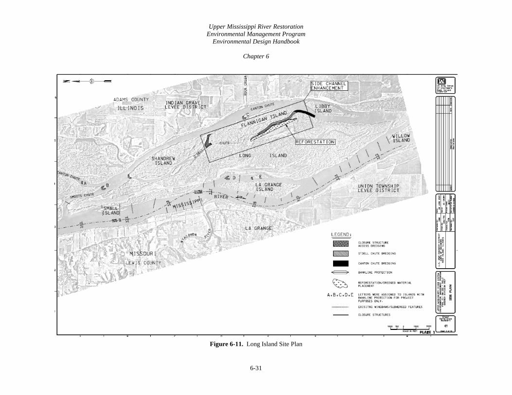
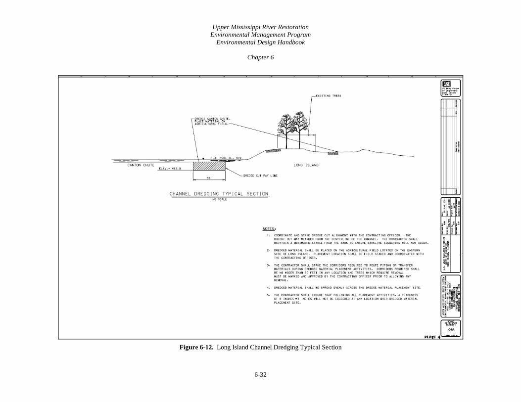
9. LONG ISLAND (GARDNER) DIVISION HREP Rock Island District, Mississippi River (RM 340.2-332.5) Contract Number DACW25-01-C-0008 Feature Constructed 2001-2002
• Included side channel restoration (photograph 6-12) and protection within O’Dell Chute including a closure structure along with shoreline protection and reforestation (figures 6-11 and 6-12).
• The material dredged from O’Dell Chute and the closure structure access channel was
placed on a 184 acre agricultural field on the eastern end of Long Island. It was determined that up to 8 inches of the sandy dredged material could be incorporated into the existing soil and still support the reforestation plan. To ensure that this depth was not exceeded, a 60 to 80 acre site was used. A berm was constructed on three sides of the placement site to ensure the dredged material settled out before draining to Long Island Lake. The berm is 2 feet in height with 2H:1V side slopes. It was assumed that the fine to medium sand making up the dredged material would settle quickly, therefore a column settling analysis was not performed.
Performance. A Performance Evaluation for this project will be finalized in FY13.
Photograph 6-12. Long Island Small Hydraulic Dredge
Upper Mississippi River Restoration Environmental Management Program
Environmental Design Handbook
Chapter 6
6-31
Figure 6-11. Long Island Site Plan
Upper Mississippi River Restoration Environmental Management Program
Environmental Design Handbook
Chapter 6
6-32
Figure 6-12. Long Island Channel Dredging Typical Section

Upper Mississippi River Restoration Environmental Management Program
Environmental Design Handbook
Chapter 6
6-33
10. SWAN LAKE HREP St. Louis District, Illinois River (RM 13.3-15.0) Feature Constructed 2001 Swan Lake (photograph 6-13) is a bottomland lake approximately 2,900 acres in size with average depth between 3 and 3.5 feet. This is the largest backwater complex in Pool 26 of the Mississippi River and one of the largest on the Illinois River. The design of the Swan Lake HREP was to provide the physical conditions necessary for creating a wide spectrum of strategies for waterfowl and fisheries management. The Swan Lake HREP consisted of riverside levee, dredging, water control/fish passage structures, pumps, an interior closure structure, islands, hillside sediment control basins, and service access. The riverside levee was necessary to reduce siltation that occurs from frequent floods from the Illinois River. Dredging provided deep water fish habitat and was accomplished in conjunction with the construction of the riverside levee. Fish passage water control structures were constructed to separate Swan Lake from the Illinois River while still providing fish passage. The hillside sediment control, which was in partnership with the NRCS, included 25 water and sediment basins in the upland watersheds to reduce sediment transported by tributaries flowing in the lake. These sediment traps were constructed by farmers on a volunteer basis after they were approached by NRCS. Islands were constructed to serve as barriers to reduce turbidity from wind generated wave action.
Photograph 6-13. Swan Lake Aerial Layout
Sedimentation continues to be one of the largest obstacles to meeting the goals of the Swan Lake HREP. The annual sediment inputs from the watershed as well as resuspension of the flocculent material by wind generated wave activity continue to contribute to lose substrates and increased turbidity. The Lower Swan Lake area is now viewed as a sacrificial sediment trap, which in future HREPS sediment traps should be designed into the project. Instead of managing this area for backwater fish habitat, this area is much more suited for management as a moist soil unit. On years with successful draw downs, abundant emergent vegetation grows, providing significant forage for waterfowl as well as for the aquatic invertebrates that colonize these areas in the spring.

Upper Mississippi River Restoration Environmental Management Program
Environmental Design Handbook
Chapter 6
6-34
Performance. A performance evaluation report was completed in 2007 to evaluate the success of the HREP. The report stated the water quality, sediment depth, and emergent vegetation improved in Middle Swan Lake, while no improvement was seen in Lower Swan Lake. It was also indicated that no submerged or rooted floating vegetation occurred in any section of the lake, likely due to an absence of a seed bank and tubers. Most notably, the report indicated fish assemblages did not improve in either section of Swan Lake. The lack of firm substrate and vegetation negatively affected the quantity of fish species present and, for the fish present, they were small and likely juvenile. In contrast, the presence of diving and dabbling ducks increased. 11. POOL 11 ISLANDS HREP Stage I and Stage II Rock Island District, Mississippi River (RM 165.5-166.0) Contract W912EK-02-C-0024 and W912EK-04-C-0007 Feature Constructed 2002-2005
• Stage I - Sunfish Lake (figure 6-13). Downstream of the deflection embankment, a series of deep-water channels totaling 13.1 ha (32.37acres) were dredged. A 2-cell containment area was constructed as part of the deflection embankment to hold the hydraulically dredged material. Both the hydraulically and mechanically dredged channels were excavated to a bottom elevation of 181.31 m (594.85 ft), a bottom width of 10 m (32.81 ft), and side slopes of approximately 3H:1V(figures 6-14 and 6-15) . The hydraulically dredged channels were dredged by an 8 inch hydraulic pipeline dredge. The mechanical dredging was done by a 275 ton crane with 3 and 4 yard buckets. Additionally, the side slopes of the hydraulically dredged channels were constructed in a stepped fashion. Dredging depths were based on historic sedimentation rates. There are two channel alignments (A & B) that follow the deflection embankment. The additional channels (D through M) connect to the first channel alignments and extend east and south towards the shoreline.
• Stage II - Mud Lake (figure 6-13). The borrow for the Mud Lake embankment was mechanically dredged from the river bottom, landward and adjacent to the embankment alignment. The resulting deep-water channel was excavated to a bottom elevation of 181.45 m (595.31 ft), a minimum bottom width of 10 m (32.81 ft), side slopes of approximately 3H:1V, and a total 11.2 ha (27.62 acres) of bottom area (figures 6-16 and 6-17). Several high spots were created with riprap in the dredged channel to retain the warmer bottom water during overwintering periods.
In the case of both islands, the dredged material was used to create the off shore revetments which would create the perimeter of the EMP site. The revetments consisted of earthen embankments covered protected by rip rap on the riverward and end sections.

Upper Mississippi River Restoration Environmental Management Program
Environmental Design Handbook
Chapter 6
6-35
Figure 6-13. Pool 11 Islands
MUD LAKE
SUNFISH LAKE

Upper Mississippi River Restoration Environmental Management Program
Environmental Design Handbook
Chapter 6
6-36
Figure 6-14. Sunfish Lake Typical Section I

Upper Mississippi River Restoration Environmental Management Program
Environmental Design Handbook
Chapter 6
6-37
Figure 6-15. Sunfish Lake Typical Section IV

Upper Mississippi River Restoration Environmental Management Program
Environmental Design Handbook
Chapter 6
6-38
Figure 6-16. Mud Lake Typical Sections A, B and C

Upper Mississippi River Restoration Environmental Management Program
Environmental Design Handbook
Chapter 6
6-39
Figure 6-17. Mud Lake Typical Sections D, E and F

Upper Mississippi River Restoration Environmental Management Program
Environmental Design Handbook
Chapter 6
6-40
To control sediment deposition in the newly dredged channels, three sedimentation traps (figure 6-18) were constructed to retain the majority of the expected sediment passing through three notched rock weirs. Each island contained a sedimentation trap on the upstream end of the island. In the design of each, the sediment trap was sized to allow for a 50-year lifespan based on historical accumulations. The traps were mechanically dredged to the approximate dimensions of 5 feet wide, 10 feet long, and 1.5 feet below flat pool. The upstream ends of the traps were located 25 to 40 feet downstream of the weirs, and 1V:3H transition slopes were used. A survey is scheduled to be completed every 5 years to monitor performance.
Figure 6-18. Sediment Trap Plan and Profile
Performance. A Performance Evaluation report was completed in 2002 after 2 years of performance. The results of the report were inconclusive as some features of the project had not yet been completed or were not operating correctly. The report did, however, note conditions for aquatic plant growth were favorable. A subsequent performance evaluation report has not been completed. 12. LAKE ODESSA HREP Stage IIB Channel Excavation Rock Island District, Mississippi River (about RM 440-435) Contract W912EK-10-C-0018 Feature Constructed 2009-2011
Upper Mississippi River Restoration Environmental Management Program
Environmental Design Handbook
Chapter 6
6-41
This feature involved dredging an existing channel (Blackhawk Yankee Chute) to create overwintering and over-summering access between the two channels. The location is within a managed water unit, and the minimum managed pool elevation is 532.5. The channel was to be excavated to 526.5. The dredge bottom width was set at 30 feet, which was a reasonable minimum distance to get a barge floated excavator into this area (figure 6-19 and 6-20 and photographs 6-14 to 6-16). Anything narrower would have required special equipment. Anything wider would have gone outside of the existing channel. The material being dredged was such that very steep side slopes could be constructed. A minimum distance between the dredge cut and the placement site was set to ensure that dredged material would not easily re-enter the dredge cut. The placement site height was established to ensure a minimum impact on wetlands (it was set at an elevation such that it could still be considered a wetland), and at a width that was reasonable to reach with the mechanical dredge. Originally, the material was to be hydraulically dredged and pumped to a moist soil management unit located on the southern edge of the project. The feature was awarded with other dredging as part of the Stage IIA project. When the contractor entered this area, it became apparent that the material to be dredged could not be efficiently dredged hydraulically, which is how the contract had been bid. (The rest of the material being dredged could be hydraulically dredged.) After many attempts to modify the existing contract, based on the contractors characteristics and abilities, and the “changed site condition” this feature was removed from Stage II. A new contract, Stage IIB was awarded which allowed for mechanical dredging. Additional dredging was also completed as part of this contract. Lessons Learned
• Have many borings, especially in backwater areas. The materials changed over a very short period of time, creating a need to change the type of construction equipment required to complete the job.
• Have adequate environmental clearance before proceeding with a project. This project required additional coordination to sidecast.
• Understand the site conditions and go into the field with team members and sponsors to discuss. A drawing indicating where tree clearing may be required is often not adequate, especially in high diversity areas.
• Field stake dredge cuts AND placement sites. A centerline situated on a drawing or using survey data does not always match the field conditions.
Performance. There has not been a Performance Evaluation report for this project as of 2012.

Upper Mississippi River Restoration Environmental Management Program
Environmental Design Handbook
Chapter 6
6-42
Figure 6-19. Blackhawk Chute/Yankee Chute Plan

Upper Mississippi River Restoration Environmental Management Program
Environmental Design Handbook
Chapter 6
6-43
Figure 6-20. Blackhawk/Yankee Chute typical Section

Upper Mississippi River Restoration Environmental Management Program
Environmental Design Handbook
Chapter 6
6-44
Photograph 6-14. Blackhawk/Yankee Chute Prior To Dredging
Photograph 6-15. Excavator Used To Dredge Back Channels
Photograph 6-16. Construction Considerations in a Backwater Area

Upper Mississippi River Restoration Environmental Management Program
Environmental Design Handbook
Chapter 6
6-45
13. PEORIA RIVERFRONT DEVELOPMENT UPPER PEORIA ISLAND SECTION 519 Stage I and Stage II Rock Island District, Illinois Waterway (RM 165.5-166.0) Contract W912EK-09-C-0052 and W912EK-10-D-0069 Feature Constructed 2009-2011
• Included the construction of an island in Peoria Lake (figure 6-21 and photograph 6-17) using geotextile containers filled with mechanically dredged material. The completed project will allow for improved habitat for fish and waterfowl in the dredged areas, a new habitat created from the dredged material placement, a reduction in the amount of sediment entering Peoria Lake from the Illinois Waterway, and recreational benefits.
• In the first project stage, a high solids dredging methodology was used to fill a three ring wide perimeter of geotextile container in 1 to 5 feet of water. During the second stage, an additional row of geotextile containers were placed on top of the existing geotextile containers and the interior of the island was filled using the same dredging technique as well as double handling with two clamshells (figure 6-22 and photograph 6-18). An approximate 450,000 cubic yards of material were dredged over 55 acres, creating a 21 acre island. The island was constructed at a price of $7 million. The process consisted of mechanically dredging the area and placing dredged materials in a concrete pump to fill the geotextile containers.
Lessons Learned
• Long bags cannot be used on corners.
• Geotextile containers need to be firmly anchored because they will roll when filling.
• Geotextile containers will sink when placed on unconsolidated materials.
• Mark geotextile containers during high flows. Boaters will hit them if they are not marked.
• Maintain geotextile containers height for longer than 48 hours or they will settle too much. Performance. There has not been a Performance Evaluation report for this project as of 2012.

Upper Mississippi River Restoration Environmental Management Program
Environmental Design Handbook
Chapter 6
6-46
Figure 6-21. Peoria Riverfront Geotextile Containers and Dredging Alignment

Upper Mississippi River Restoration Environmental Management Program
Environmental Design Handbook
Chapter 6
6-47
Figure 6-22. Peoria Riverfront Upper Island Section View Stage II

Upper Mississippi River Restoration Environmental Management Program
Environmental Design Handbook
Chapter 6
6-48
Photograph 6-17. Peoria Riverfront Island Stage 1
Photograph 6-18. Peoria Riverfront Island Stage II

Upper Mississippi River Restoration Environmental Management Program
Environmental Design Handbook
Chapter 6
6-49
E. REFERENCES Claflin, T. O. 1977. Project report - Lake Onalaska rehabilitation feasibility study, River Studies
Center, University of Wisconsin-LaCrosse Eckblad, J. W., Petersen, N. L., Ostlic, K., and Tempte, A. 1977. The morphometry, benthos, and
sedimentation rates of a floodplain lake in Pool 9 of the Upper Mississippi River, American Midland Naturalist 97, 433-43
McHenry, J. R., Ritchie, J. C., Cooper, C. M., and Verdon, J. 1984. Recent rates of sedimentation in
the Mississippi River, Contaminants in the Upper Mississippi River. J. G. Wiener, R. V. Anderson, and D.R. McConville, eds. Butterworth Publishers, Stoneham, MA. 99-117
Natural Resources Conservation Service. NRCS Conservation Practice Standard. Code 350:
Sediment Basin, 2001 Natural Resources Conservation Service. NRCS Conservation Practice Standard. Code 638:
Sediment Basin, 2001 Korschgen, C. E., Jackson, G. E., Muessig, L. F., and Southworth, D. C. 1987. Sedimentation in Lake
Onalaska, Navigation Pool 7, Upper Mississippi River, since impoundment, Water Resources Bulletin 23, 221-26
Rogala, J.T., P.J. Boma, and B.R. Gray. 2003. Rates and patterns of net sedimentation in backwater
of Pools 4, 8, and 13 of the Upper Mississippi River. U.S. Geological Survey, Upper Midwest Environmental Sciences Center, La Crosse, WI
USACE, EM 1110-2-1300, Government Estimates and Hired Labor Estimates for Dredging, Apr 5, 1985
EM 1110-2-5025, Dredging and Dredged Material Disposal, Mar 25, 1983 EM 1110-2-5026, Dredged Material Beneficial Uses, Jun 30, 1987 EM-1110-2-5027, Confined Disposal of Dredged Material, Sep 30, 1987 ETL 1110-2-573, Engineering and Design: Construction Cost Estimating Guide for Civil Works and Appurtenant Structures, Apr 10, 2009
USACE, ERDC/EL TR-03-1, Evaluation of Dredged Material Proposed for Disposal at Island, Nearshore, or Upland Confined Disposal Facilities - Testing Manual, Upland Testing Manual, Jan 2003 ERDC/EL TR-08-29, Technical Guidelines for Environmental Dredging of Contaminated Sediments, Upland Testing Manual, Sep 2008 ERDC TN-DOER-C18, Confined Disposal Facility (CDF) Containment Features: A Summary of Field Experience, Aug 2000
Upper Mississippi River Restoration Environmental Management Program
Environmental Design Handbook
Chapter 6
6-50
USACE, Dredging Operations Technical Support Program. http://el.erdc.usace.army.mil/dots/dots.html
USACE, Report to Congress: An Evaluation of the Upper Mississippi River System Environmental Management Program, 1997
USACE, US EPA, EPA-823-B-98-004, Evaluation of Dredged Material Proposed For Discharge in Waters of the U.S. – Testing Manual, Inlands Testing Manual, Feb 1998
US EPA842-B-92-008, Evaluating Environmental Effects of Dredged Material Management Alternatives – A Technical Framework, May 2004