Embed Size (px)
Citation preview
UPNP® REMOTE ACCESS—CONNECTING TWO HOME OR SMALL BUSINESS NETWORKS
June 2012

UPnP® Remote Access—
2
ABSTRACT
UPnP Remote Access technologies enable a UPnP device or UPnP control Point, such as a mobile phone, not currently located in the home or small business network to be securely connected to the home or small business network. This allows the remote UPnP device or control point to discover and interact securely with any of the UPnP device or control points that are contained within the home or small business network. UPnP Forum has recently published the version 2 Remote Access specifications in August 2011. The key feature of this new version of the specifications is to enable seamless connection between two home or small business networks thus allowing UPnP devices or control point in a home or small business network discover and interact with UPnP device and control point in another home or small business network using existing UPnP protocols. The newly published specifications address a number of features including solution for address collision when connecting two home or small business networks together, provisioning of remote access services, network address translation, and the concept of virtual device that allows multiple devices or services to be exposed to a remote home or small business network under the framework of a single device. The purpose of this white paper is to discover these new exciting features of the latest version of the remote access specifications.
CONTENTS
Abstract ........................................................................................................................................... 2
Contents .......................................................................................................................................... 2
References ....................................................................................................................................... 3
Introduction to UPnP ....................................................................................................................... 5
UPnP Remote Access Overview ....................................................................................................... 6
UPnP Remote Access Use Cases ...................................................................................................... 8
UPnP Remote Access Architecture Paradigm ................................................................................. 8
UPnP Remote Access Components ................................................................................................. 9
Connection Establishment Between Two Home or Small Business Networks ............................. 11
Filtering of Devices Exposed to the Remote Network .................................................................. 13
Resolving Address Collision ........................................................................................................... 13
Remote Access Deployment with NAT .......................................................................................... 14

UPnP® Remote Access—
3
Conclusion ..................................................................................................................................... 16
Join UPnP Forum ........................................................................................................................... 17
REFERENCES
‐ [DEVICE] – UPnP Device Architecture, version 1.0. Available at: http://www.upnp.org/specs/arch/UPnP‐arch‐DeviceArchitecture‐v1.0‐20080424.pdf. Latest version available at: http://www.upnp.org/specs/arch/UPnP‐DeviceArchitecture‐v1.0.pdf.
‐ [DEVICE‐IPv6] – UPnP Device Architecture, version 1.0., Annex A – IP Version 6 Support. Available at: http://www.upnp.org/resources/documents/AnnexA‐IPv6_000.pdf
‐ [ICC] – InboundConnectionConfig:1, UPnP Forum, Available at: http://www.upnp.org/specs/ra/UPnP‐ra‐InboundConnectionConfig‐v1‐Service‐20090930.pdf. Latest version available at: http://www.upnp.org/specs/ra/UPnP‐ra‐InboundConnectionConfig‐v1‐Service.pdf.
‐ [RAArchitecture] – RAArchitecture:2, UPnP Forum, Available at: http://www.upnp.org/specs/ra/UPnP‐ra‐RAARchitecture‐v2.pdf.
‐ [RAClient] – RAClient:1, UPnP Forum, Available at: http://www.upnp.org/specs/ra/UPnP‐ra‐RAClient‐v1‐Device.pdf.
‐ [RADAConfig] – RADAConfig:2, UPnP Forum, Available at: http://www.upnp.org/specs/ra/UPnP‐ra‐RADAConfig‐v2‐Service.pdf.
‐ [RADASync] – RADASync:2, UPnP Forum, Available at: http://www.upnp.org/specs/ra/UPnP‐ra‐RADASync‐v2‐Service.pdf.
‐ [RADiscoveryAgent] – RADiscoveryAgent:1, UPnP Forum, Available at: http://www.upnp.org/specs/ra/UPnP‐ra‐RADiscoveryAgent‐v2‐Device.pdf.
‐ [RAServer] – RAServer:2, UPnP Forum, Available at: http://www.upnp.org/specs/ra/UPnP‐ra‐RAServer‐v2‐Device.pdf.
‐ [RATAConfig] – RATAConfig:1, UPnP Forum, Available at: http://www.upnp.org/specs/ra/UPnP‐ra‐RATAConfig‐v1‐Service.pdf.

UPnP® Remote Access—
4
‐ [IGD] – InternetGatewayDevice:1, UPnP Forum, November, 2001 Available at: http://www.upnp.org/specs/gw/igd1?.
‐ [RFC 1889] – IETF RFC 1889, RTP: A Transport Protocol for Real‐Time Applications, H. Schulzrinne, S. Casner, R. Frederick, V. Jacobson, January 1996. Available at: http://www.ietf.org/rfc/rfc1889.txt.
‐ [RFC 1918] – IETF RFC 1918, Address Allocation for Private Internets, Y. Rekhter, et. Al, February 1996 Available at: http://www.ietf.org/rfc/rfc1918.txt
‐ [RFC 2119] – IETF RFC 2119, Key words for use in RFCs to Indicate Requirement Levels, S. Bradner, March 1997. Available at: http://www.ietf.org/rfcs/rfc2119.txt.
‐ [RFC 2131] – IETF RFC 2131, Dynamic Host Configuration Protocol, R. Droms, March 1997 Available at: http://www.ietf.org/rfc/rfc2131.txt
‐ [RFC 2516] – IETF RFC 2516, A Method for Transmitting PPP Over Ethernet (PPPoE), L. Mamakos, et. Al, February 1999 Available at: http://www.ietf.org/rfc/rfc2516.txt
‐ [RFC 3056] – IETF RFC 3056, Connection of IPv6 Domains via IPv4 Clouds, B. Carpenter, K. Moore, February 2001 Available at: http://www.ietf.org/rfc/rfc3056.txt
‐ [RFC 3489] – IETF RFC 3489, STUN ‐ Simple Traversal of User Datagram Protocol (UDP) Through Network Address Translators (NATs), J. Rosenberg, et. Al, March 2003 Available at: http://www.ietf.org/rfc/rfc3489.txt
‐ [RFC 3550] – IETF RFC 3550, RTP: A Transport Protocol for Real‐Time Applications, H. Shulzrinne, et. Al, July 2003 Available at: http://www.ietf.org/rfc/rfc3550.txt
‐ [RFC 4380] – IETF RFC 4380, Teredo: Tunneling IPv6 over UDP through Network Address Translations (NATs), C. Huitema, February 2006 Available at: http://www.ietf.org/rfc/rfc4380.txt
‐ [RFC 3986] – IETF RFC 3986, Uniform Resource Identifier (URI): Generic Syntax, Tim Berners‐Lee, et. Al, January 2005. Available at: http://www.ietf.org/rfc/rfc3986.txt

UPnP® Remote Access—
5
‐ [UWP] UPnP white paper, September 2010, http://upnp.org/resources/whitepapers/UPnPWhitePaper_2010.pdf.
‐ [ETSI ES 282 001 (2009)] – TISPAN: NGN Functional Architecture, Feb. 2009. Available at: http://portal.etsi.org/docbox/TISPAN/Open/NGN_LATEST_DRAFTS/RELEASE3/02067‐ngn‐r3v330.pdf
‐ [TISPANCust] – TISPAN Customer Premises Networks: Protocol Specification. Available at: http://pda.etsi.org/exchangefolder/ts_185010v020101p.pdf
‐ [RFC 4787] – IETF RFC 4787, Network Address Translation (NAT) Behavioral Requirements for Unicast UDP, C. Jennings, F. Audet, January 2007[RFC 2136] – IETF RFC 2136, Dynamic Updates in the Domain Name System (DNS Update), P. Vixie, et. al, April 1997
‐ [RFC 2782] – IETF RFC 2782 – A DNS RR for specifying the location of services (DNS SRV), A. Gulbrandsen, et. al, February 2000
‐ [RFC 5389] – IETF RFC 5389, Session Traversal Utilities for NAT (STUN), J. Rosenberg, et. al,, October 2008
‐ [BEHAVE TURN] – IETF Internet Draft, Traversal Using Relays around NAT (TURN): Relay Extensions to Session Traversal Utilities for NAT (STUN), draft‐ietf‐behave‐turn‐16, J. Rosenberg, July 2009
‐ [RFC 5128] – IETF RFC 5128, State of Peer‐to‐Peer (P2P) Communication accress Network Address Translators (NATs), P. Srisuresh, et. al., March 2008
‐ [P2P Com] – Proceedings of the Usenix 2005 Annual Technical Conference, pp. 179‐192, Peer‐to‐Peer Coummunication Across Network Address Translators, B. Ford, P. Srisuresh, D. Kegel,, March 2005]
‐ [DLNA Design Guidelines] – DLNA Networked Device Interoperability Guidelines, Available at: http://www.dlna.org/industry/certification/guidelines/
INTRODUCTION TO UPNP
Universal Plug and Play is a set of networking protocols proposed by the UPnP Forum (www.upnp.org).
The goal of UPnP technology is to provide a broad industry initiative that simplifies networking for small businesses and consumers. It intends to easily connect computers and other devices
UPnP® Remote Access—
6
into a network ‘hub’ from which to access data, transport media and offer network connectivity under the command of any connected control device.
UPnP device control protocols (DCP) are built upon open, Internet‐based communication standards and can therefore be implemented on any operating system. It works with any type of physical networking media that supports IP, wired or wireless, and offers a multitude of options.
UPnP devices are "plug‐and‐play" in that when connected to a network they automatically announce their network address and supported device and services types, enabling clients that recognize those types to immediately begin using the device.
Any Control Point (CP) connected to the LAN will broadcast search requests to identify available UPnP devices and their supported actions. Control Point can then start invoking these discovered actions. Actions invoked will initiate asynchronous operations and return operation IDs via which results can subsequently be obtained.
UPnP device and service standards are defined and published for Internet gateways/routers, audio‐video media devices, printers, scanners, climate control, lighting and wireless LAN access points, digital security cameras, and advanced features such as security, remote user interface and quality of service.
There are various device control protocols such as Internet Gateway Device (UPnP IGD), Audio and Video (UPnP AV, upon which DLNA is partially based), Remote Access (UPnP RA) and Device Management (UPnP DM).
For more information, UPnP Forum has published a UPnP white paper in September 2010 [UWP].
UPNP REMOTE ACCESS OVERVIEW
Remote Access to UPnP Networks enables a remote UPnP device or UPnP control Point to connect to the home or small business network and interact with the UPnP device or control point physically attached to the home or small business network. During this process it is expected that the remote user will experience the remote device behaving in a similar way as in the home network. In practice, the overall user experience will be degraded due to the limitations induced by external factors, such as network latencies and bandwidth, but nevertheless the remote device will have to go to the same steps (e.g. IP addressing, discovery, description, control, eventing) as any UPnP device present in a home or small business network.
Remote Access architecture undertakes the provisions needed in order to minimize the adverse effects of the internal and external factors and bring the remote user experience as close as possible to the one available in the local area network.

UPnP® Remote Access—
7
In a home (or small business) to home (or small business) scenario two networks are connected with each other via the remote access gateway devices. This allows services and devices of one home to be accessible to services and devices of another home and vice‐versa
A typical Remote Access scenario that connects two home or small business networks is depicted in the above figure, where we have two gateway devices that connect two home or small business networks. A gateway in a home or small business network connects to the internet via an access network and establishes a remote access connection with a remote network via public internet backbone and through the gateway located in the remote network. There are cases when, due to various reasons, the gateway cannot establish remote access connection by itself and it needs the help of some support services that can be hosted in the ISP network or can be hosted in the internet by a 3rd party service provider.
In this environment, it is highly probable that one or more of the intermediate network elements deploying NAT and firewall techniques will break the end‐to‐end connectivity between
UPnP® Remote Access—
8
the devices. Generally speaking, the problems introduced by NAT boxes are well understood and protocol designers have created built‐in capabilities to transverse several NATs on the initiator side. However, on the receiving side, things are more complex and hosts behind NATs are not able to accept connections without support from some 3rd party support services located in the public internet. The remote access specifications have considered these factors and provided recommendations for deployment when networks are behind NAT.
UPNP REMOTE ACCESS USE CASES
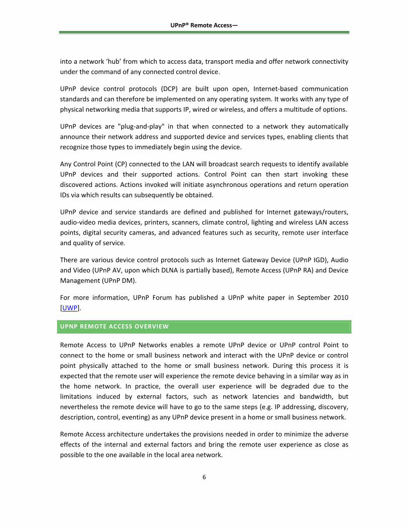
There are many examples of use cases where remote access is needed. Here is an example use case for connecting two home networks through remote access:
- Bob would like to share his child’s latest photos with Alice. Bob and Alice’s home networks are connected through UPnP remote Access mechanism. Alice discovers desired content on Bob’s media server. Alice selects her TV as a media renderer and plays a slide show on her TV using content sourced from Bob’s media server. The remote access connection between the two homes is setup using UPnP Remote Access Server (RAS) located in each home and devices in one network see devices in another network. The set of devices that are visible in a remote network are set by establishing filters in each RAS.
UPNP REMOTE ACCESS ARCHITECTURE PARADIGM
The Remote Access Architecture envisions recreating the UPnP experience for devices that are not physically attached to the home network. There are two concepts that make this vision possible: a transport channel, which provides the security for UPnP Device Architecture

UPnP® Remote Access—
9
protocols and for any associated protocols that are used in the context of various DCPs, and a Discovery Agent, which enables a UPnP device or service to be visible in a remote location and controls the visibility of these devices according to some filters configured by the home owner.
Remote Access Architecture Paradigm
The experience provided by the Remote Access Architecture to a Remote Device is similar to the one encountered in home, with certain limitations due to the available bandwidth on the path between the remote device and the home network. The figure above shows how a home network or small business network are connected to a remote device and how a discovery agent makes devices and services visible. The remote device in the figure can represent a Remote Access server residing in the remote network.
UPNP REMOTE ACCESS COMPONENTS
The figure below illustrates the set of components which enable two home networks or small business networks to connect to each other via the RAS (Remote Access Server) devices. A RAS is the peer physical device located in a home network or small network that exposes to another RAS in a remote home network or small network the UPnP devices and services available in the physical network.

UPnP® Remote Access—
10
Remote Access Components for Connecting Two Home Networks or Small Networks
The Remote Access Secure Channel can be implemented using different mechanisms. The Remote Access Transport Agent (RATA) provides the secure communication channel between the two home networks or small networks. The RATA parameters and options are configured by the remote access administrator via the RATAConfig service. A RATA may support multiple transport mechanisms, e.g. IPsec, TLS, etc.
The InboundConnectionConfig service allows the remote access administrator to verify if the RAS is reachable and to configure the settings that will allow the Remote Access Client to establish a RATA connection to the RAS.
The functionality of the Network Image Aggregator is provided by the Remote Access Discovery Agent (RADA) device together with the associated RADA Listener and RADA Relay functionalities. The RADA Listener is a control point that is constantly monitoring the UPnP SSDP messages in the local network allowing it to detect when devices are joining and leaving the network or when they are changing status. All changes detected by the RADA Listener are feed to the RADA.
UPnP® Remote Access—
11
The RADA has two components: the RADASync service and the RADASync Control Point. The role of the RADASync is to act as a synchronization sink allowing a RADASync Control Point, acting as a synchronization source, to push network image information about a remote network. This is a one‐way sync process and in order to synchronize both network endpoints there is a need for two RADASync relationships, one form each direction. The synchronization process may be asymmetric and is determined by the filters that are configured by the remote access administrator via the RADAConfig service.
A local RADA is informed about the status changes in a UPnP remote network by the corresponding remote RADA. Those changes are notified to the RADA Relay that is reconstructing the original UPnP SSDP messages, which were sent by the remote devices. The RADA relay then distributes these messages into the local network. Additionally, the RADA Relay will respond on behalf of the remote devices to SSDP queries issued in the local network.
The multicast domain separation is done by the routing module that prevents the UPnP multicast traffic to travel inside the remote access secure channel provided by RATA.
CONNECTION ESTABLISHMENT BETWEEN TWO HOME OR SMALL BUSINESS NETWORKS
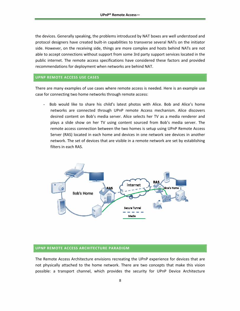
In order to connect two home or small business networks through RAS, the connecting RAS needs to know the information of the remote RAS including the IP address, security association etc. This sharing information can be stored in a Remote Access Application Server (Remote Access AS) managed by the service provider.
1. When User 1 wants to share his home with another User 2 , the RAS 1 in user 1’s network will update sharing rules in the Remote Access Sharing Rules Server. The only needed information is User 1 shares his home to user 2
2. On connection, RAS 2 retrieves information from the Remote Access AS to know if someone shares their home with User 2.
3. Based on the Sharing Rules User 2 establishes a Remote Access Session with User 1

UPnP® Remote Access—
12
Remote Access AS could be a presence server in SIP/IMS application or a web server based on HTTP mechanism. There are several mechanisms that can be used to setup connection between two RAS. The first approach is to use SIP to establish the connection between the RAS using the IMS network [ETSI ES 282 001 (2009)] , the second approach is to use SIP by passing RATA parameters between two RAS, and the third approach is where a connection can be established over the top. The deployment model should take care of these different approaches; a Remote Access Product could be only compliant with one, two or three connection establishment solutions. In addition to these scenarios, the solution will take care of the different profiles available between the different homes – IPsec VPN, OpenVPN or without VPN. To be able to manage a kind of interoperability between different solutions and a service provider’s roadmap (IMS and / or IPv6 deployment), a Remote Access Product should be compliant with the different connection establishment solutions.
The Connection Establishment Agent in a RAS enables the local RAS to locate the remote RAS across a WAN. The Connection establishment of RA devices over the WAN enables the exchange of security parameters and credentials needed to successfully establish a remote access connection. The connection establishment interaction is a handshake in which the initiating RA device (RAS or RAC) makes an ‘offer’ which includes the UPnP RA security profiles supported by that device. The profiles include: IPSec based on certificates profile, IPSec based on shared key null policy profile, IPSec based on shared key advanced policy profile and OpenVPN profile. The receiving RA device (RAS or RAC) makes a selection of one of the profiles which will be used to establish the RA tunnel. This interaction is shown in Figure below.
Handshake and Connection between RA Devices over the WAN
The handshake interaction could also implement a model whereby the initiating RA device sends to the receiving RA device a set of parameters with which it would like to establish a RA connection. If the receiving side accepts these parameters the secure tunnel would then be set up based on these parameters.
UPnP® Remote Access—
13
FILTERING OF DEVICES EXPOSED TO THE REMOTE NETWORK
The remote access specifications provide mechanisms to setup a filter which controls which devices will be exposed or will not be exposed to the remote network. This is device level filtering which is performed by UPnP actions exposed by the [RADAConfig] service specification. The latest publication of the remote access specifications has also introduced the concept of virtual device in order to allow setting filters even at the service level. A virtual device represents a unified view of services and devices to be exposed to the remote network under a single device description. To the remote network the virtual device is represented as a regular device with its own device description, however, in reality the device description includes a composition of services and devices from multiple devices into the local network that are transparent to the remote network. In contrast to the filtering mechanism which allows only configuring devices or services for each device to be exposed to the remote network with its own device description, the virtual device can be used to expose only the virtual device to the remote network without allowing the remote network to comprehend actual devices in the local network. In the virtual device scenario, the remote network only sees a single device (i.e., the virtual device) with some services that the remote device can access.
RESOLVING ADDRESS COLLISION
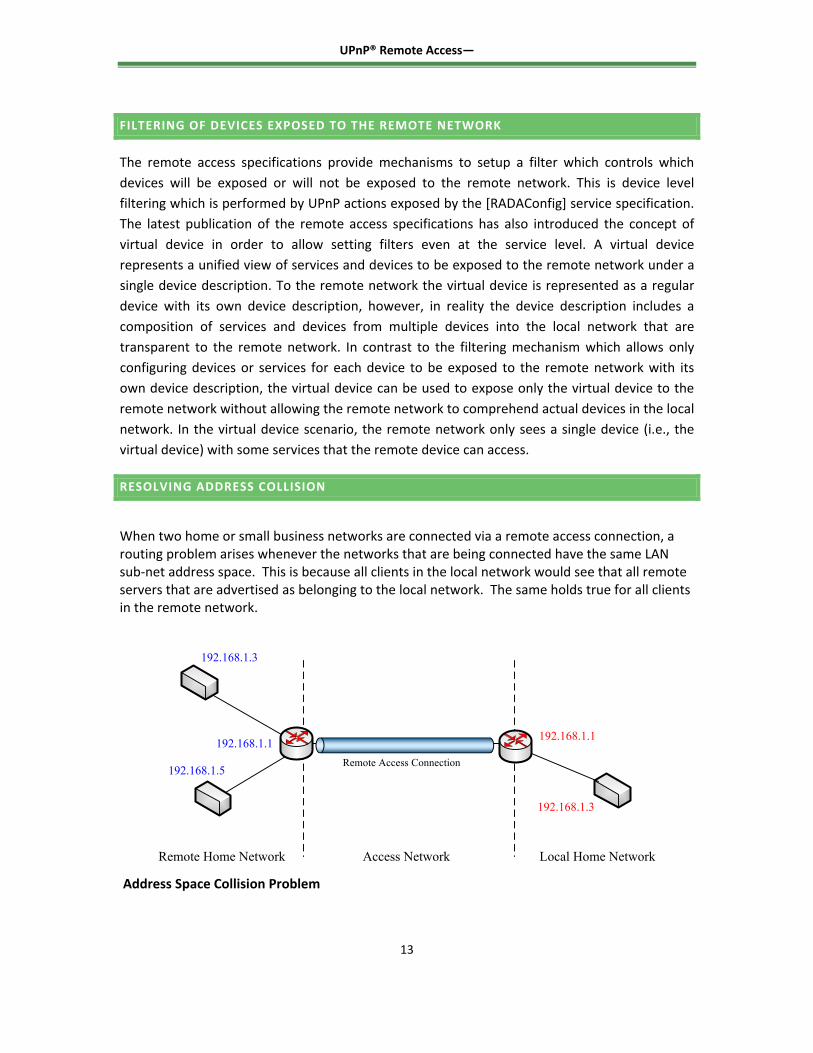
When two home or small business networks are connected via a remote access connection, a routing problem arises whenever the networks that are being connected have the same LAN sub‐net address space. This is because all clients in the local network would see that all remote servers that are advertised as belonging to the local network. The same holds true for all clients in the remote network.
192.168.1.3
192.168.1.5
192.168.1.1 192.168.1.1
192.168.1.3
Remote Home Network Access Network Local Home Network
Remote Access Connection
Address Space Collision Problem
UPnP® Remote Access—
14
There are several approaches to resolve this problem. The first approach is to randomize the private IP address allocation. This is a collision avoidance approach. Instead of HG’s always using a manufacturer default for the LAN address, each HG should use a randomizing function to choose a private network at first out‐of‐the‐box boot. Alternatively, UPnP IGD can be used to perform a one‐time randomize. The following analysis presents how well this collision avoidance technique performs for the typical RAS‐to‐RAS use case. Assuming that a home requires at most 30 host/devices and therefore 5 address bits are required for each home, such a randomizing function would use the following RFC 1918 address spaces:
19 bits in the 10/8 prefix (520200 address), and
15 bits in the 172.16/12 prefix (32768 addresses), and
11 bits in the 192.168/16 prefix (2048 addresses.
This gives a total of 555,016 distinct private network addresses each of which can support 30 hosts.
The second approach to resolve address collision problem is to use address translation approach. The IP addresses used in one home network that collide with the IP addresses being used in another home network, will be translated to a different address space. This translation will be done by the ALG (Application Layer Gateway) incorporated into the RATA and activated only when a collision is detected. If the RADA detects a collision of the local address space then the RADA chooses an address space that is different from the one being used in the other networks that are connected through the remote access channel. The ALG does the address translation for the RADA to the newly selected address space after detection of address collision. It is recommended that after selecting a new address space, the RAS should check again whether there is an address collision. It is also possible that the ALG can reside only in one side of the network.
The third approach is to transition to IPv6 . It must be noted that this procedure does not eliminate the possibility of address space collisions but will lead to a situation where, in practice, it will be highly unlikely that the access network and home network will be sharing the same address space. The transition to IPv6 will eliminate the problem of address space collision.
REMOTE ACCESS DEPLOYMENT WITH NAT
The Network Address Translation (NAT) has been deployed by some Service Providers to deal with the IPv4 address. NATs are deployed in routers and help to reduce the IPv4 address usage by supporting multiple devices behind a single public IP address. It allocates private IP addresses [RFC 1918] to these devices and manages the dynamic translation/mapping between the internal and external IP addresses / ports. These dynamic address translations create a

UPnP® Remote Access—
15
problem for a remote access server that tries to establish a connection to another remote access server because the “external” IP addresses / ports to the remote access server may no longer be static.
There are a variety of NAT implementations available in the market today. Description of the NAT behaviors are outside the scope of this document but a detail description of NAT behaviors are available in [RFC 4787]. The following NAT behaviors are addressed in this remote access:
‐ Endpoint Independent Mapping (also referred to as Full Cone NAT) ‐ Address Dependent Mapping (also referred to as Restricted Cone) ‐ Address and Port Dependent Mapping (also referred to as Port Restricted NAT) ‐ (Unique) Address and Port Dependent Mapping (also referred to as Symmetric NAT)
The following techniques are considered:
‐ Dynamic Domain Name System (DNS) update [RFC 2136] ‐ Domain Name System Resource Record for Location of Services (DNS SRV) [RFC 2782] ‐ Session Traversal Utilities for NAT (STUN) [RFC 5389] ‐ Traversal using relays around NAT (TURN) [BEHAVE TURN] ‐ Connection Reversal mechanism for establishing a P2P connection [RFC 5128] ‐ Hole Punching mechanism for establishing a P2P connection [P2P Com]
The table below summarizes the use of the above techniques and combination of these techniques to help establish a connection between a client (e.g., local RAS) and a server (e.g., remote RAS) in the presence of the various NAT permutations:

UPnP® Remote Access—
16
CONCLUSION
This white paper described the key new features and functionalities addressed in the Remote Access Version 2 Specifications published in August 2011. The published specifications are available for implementers at http://upnp.org/specs/ra/ra2. The key features addressed by the specifications include
‐ Remote Access connection between two home or small business networks o Enables devices or services in one network to access devices or services in
another network. ‐ Enhanced filtering
o Enables to set filters about which devices and services are to be exposed to the remote network by introducing virtual device description.
‐ Address Collision Resolution o Approaches to resolve address collision when connecting two networks by
remote access connection including address randomization and address translation mechanisms.
‐ Provisioning of Remote Access Connection

UPnP® Remote Access—
17
o Several approaches including a service provider based mechanism to provision a remote access connection between two networks.
The future direction of this work may include remote access connection in multi‐home or multi‐network environments, the impact of IPv6 transition on remote access, etc.
JOIN UPnP FORUM
UPnP Forum is open to any company interested in making home or office networking easy for users. UPnP Forum seeks to facilitate seamless connectivity of devices and simplify network implementation in home and small business environments. Toward this end, UPnP Forum Members work together to define and publish Device Control Protocols (DCPs) built upon open, Internet‐based communications standards. UPnP Forum offers two levels of membership—basic and implementer, catering to a variety of member needs.
Basic Membership offers the following opportunities with no annual fee:
‐ Leadership. Design and drive the device descriptions for your industry's products and services and the products with which they will interact.
‐ Leverage your assets. Ensure that your legacy products and new products can talk and interact dynamically on UPnP network.
‐ Learn more. Gain a broad understanding of UPnP Forum technology and its opportunities for your products and industry.
‐ Leverage Forum market development. Gain access to UPnP Forum events including Plugfest compatibility workshops, UPnP Forum Partner Pavilions at major trade shows, use of the UPnP Forum Member logo, and public relations support.
‐ Find partners. Interact with and leverage the resources of the large, diverse group of organizations actively creating and investing in UPnP Forum technology.
UPnP Forum certification process is open to vendors who are Implementer level members of UPnP Forum and have devices that support UPnP Forum technology. The annual fee for implementer membership in UPnP Forum is US $5,000.
Implementer Members enjoy all the benefits of Basic Members and the following additional benefits:
‐ Access to the official UPnP Certification test tool and ability to test devices for UPnP® Certification.
‐ Special assistance in obtaining technical support from the test tool product support team.
UPnP® Remote Access—
18
‐ License to the UPnP® Certification Mark for display on certified products and associated product marketing collateral.
‐ Ability to include the member company’s certified devices in the online listing of certified devices.
Steering Committee Members provides UPnP Forum leadership and business direction, while delegating to several technical working committees to identify and define UPnP services, device controls and protocols (DCPs) and usage scenarios. Membership to the Steering Committee is by election which is open to any Implement Member. Currently, the UPnP Forum Steering Committee is composed of representatives from the following companies:
For more information about joining UPnP Forum or about certifying your product, visit: http://www.upnp.org. Send questions of an administrative nature to UPnP Forum [email protected] with the text “UPnP Administration Request” in the subject line of your message.
Contact
Dr. Alan Messer President and Chairman UPnP Forum [email protected] +1 503‐619‐5223


![[When connecting one PC using a Global connection ... · [When connecting one PC using a Global connection (connecting with UPnP OFF)] ... 192.168.0.31 TCP 444 UDP 65024 IP address](https://img.dokumen.tips/doc/110x75/5b148fef7f8b9a347c8dbe08/when-connecting-one-pc-using-a-global-connection-when-connecting-one-pc.jpg)