Embed Size (px)
Citation preview
UPnP™ Device Architecture 1.0 Version 1.0.1, 06 May 2003
© 1999-2003 Contributing Members of the UPnP™ Forum. All rights reserved.
UPnP™ is a certification mark of the UPnP™ Implementers Corporation.
Table of Contents Introduction ........................................................................................ 1
What is UPnP™ Technology?.................................................................... 1 UPnP™ Forum..................................................................................... 1 In this document................................................................................. 2 Audience .......................................................................................... 4 Required vs. recommended.................................................................... 4 Acronyms.......................................................................................... 5 References and resources ...................................................................... 5
0. Addressing....................................................................................... 6 0.1 Addressing: Determining whether to use Auto-IP...................................... 6 0.2 Addressing: Choosing an address ......................................................... 6 0.3 Addressing: Testing the address.......................................................... 7 0.4 Addressing: Periodic checking for dynamic address availability .................... 8 0.5 Addressing: Device naming and DNS interaction....................................... 8 0.6 Addressing: Name to IP address resolution ............................................. 9 0.7 Addressing references...................................................................... 9
1. Discovery ...................................................................................... 10 1.1 Discovery: Advertisement ................................................................12 1.2 Discovery: Search ..........................................................................17 1.3 Discovery references ......................................................................21
2. Description .................................................................................... 22 2.1 Description: Device description .........................................................24 2.2 Description: UPnP Device Template ....................................................28 2.3 Description: Service description.........................................................29 2.4 Description: UPnP Service Template ...................................................34 2.5 Description: Non-standard vendor extensions.........................................35 2.6 Description: UPnP Template Language for devices ..................................36 2.7 Description: UPnP Template Language for services..................................38 2.8 Description: Retrieving a description...................................................40 2.9 Description references ....................................................................42
3. Control ......................................................................................... 43 3.1 Control: Protocols .........................................................................44 3.2 Control: Action .............................................................................45 3.3 Control: Query for variable ..............................................................51 3.4 Control references.........................................................................51
4. Eventing........................................................................................ 52 4.1 Eventing: Subscription ....................................................................54 4.2 Eventing: Event messages ................................................................60 4.3 Eventing: UPnP Template Language for eventing ....................................63 4.4 Eventing: Augmenting the UPnP Template Language................................64 4.5 Eventing references .......................................................................65
5. Presentation .................................................................................. 66 5.1 Presentation references ..................................................................67
A. IP Version 6 Support ........................................................................ 68 A.1 Introduction................................................................................68 A.2 General Principles ........................................................................68 A.3 Addressing..................................................................................70 A.4 Discovery ...................................................................................74 A.5 Description.................................................................................77 A.6 Control......................................................................................77 A.7 Eventing ....................................................................................78 A.8 Presentation ...............................................................................78 A.9 References .................................................................................78
Glossary ........................................................................................... 79

1
Introduction
What is UPnP™1 Technology?
UPnP™ technology defines an architecture for pervasive peer-to-peer network connectivity of intelligent appliances, wireless
devices, and PCs of all form factors. It is designed to bring easy-to-use, flexible, standards-based connectivity to ad-hoc or
unmanaged networks whether in the home, in a small business, public spaces, or attached to the Internet. UPnP technology
provides a distributed, open networking architecture that leverages TCP/IP and the Web technologies to enable seamless
proximity networking in addition to control and data transfer among networked devices.
The UPnP Device Architecture (UDA) is more than just a simple extension of the plug and play peripheral model. It is designed to
support zero-configuration, "invisible" networking, and automatic discovery for a breadth of device categories from a wide range
of vendors. This means a device can dynamically join a network, obtain an IP address, convey its capabilities, and learn about
the presence and capabilities of other devices. Finally, a device can leave a network smoothly and automatically without leaving
any unwanted state behind.
The technologies leveraged in the UPnP architecture include Internet protocols such as IP, TCP, UDP, HTTP, and XML. Like the
Internet, contracts are based on wire protocols that are declarative, expressed in XML, and communicated via HTTP. Using
internet protocols is a strong choice for UDA because of its proven ability to span different physical media, to enable real world
multiple-vendor interoperation, and to achieve synergy with the Internet and many home and office intranets. The UPnP
architecture has been explicitly designed to accommodate these environments. Further, via bridging, UDA accommodates media
running non-IP protocols when cost, technology, or legacy prevents the media or devices attached to it from running IP.
What is "universal" about UPnP technology? No device drivers; common protocols are used instead. UPnP networking is media
independent. UPnP devices can be implemented using any programming language, and on any operating system. The UPnP
architecture does not specify or constrain the design of an API for applications; OS vendors may create APIs that suit their
customers’ needs.
UPnP™ Forum
The UPnP Forum is an industry initiative designed to enable easy and robust connectivity among stand-alone devices and PCs
from many different vendors. The UPnP Forum seeks to develop standards for describing device protocols and XML-based device
schemas for the purpose of enabling device-to-device interoperability in a scalable networked environment.
The UPnP Implementers Corporation (UIC) is comprised of UPnP Forum member companies across many industries who promote
the adoption of uniform technical device interconnectivity standards and testing and certifying of these devices. The UIC
develops and administers the testing and certification process, administers the UPnP logo program, and provides information to
1 UPnP™ is a certification mark of the UPnP™ Implementers Corporation.
2
UIC members and other interested parties regarding the certification of UPnP devices. The UPnP device certification process is
open to any vendor who is a member of the UPnP Forum and UIC, has paid the UIC dues, and has devices that support UPnP
functionality. For more information, see http://www.upnp-ic.org.
The UPnP Forum has set up working committees in specific areas of domain expertise. These working committees are charged
with creating proposed device standards, building sample implementations, and building appropriate test suites. This document
indicates specific technical decisions that are the purview of UPnP Forum working committees.
UPnP vendors can build compliant devices with confidence of interoperability and benefits of shared intellectual property and
the logo program. Separate from the logo program, vendors may also build devices that adhere to the UPnP Device Architecture
defined herein without a formal standards procedure. If vendors build non-standard devices, they determine technical decisions
that would otherwise be determined by a UPnP Forum working committee.
In this document
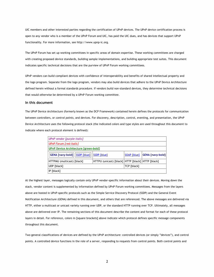
The UPnP Device Architecture (formerly known as the DCP Framework) contained herein defines the protocols for communication
between controllers, or control points, and devices. For discovery, description, control, eventing, and presentation, the UPnP
Device Architecture uses the following protocol stack (the indicated colors and type styles are used throughout this document to
indicate where each protocol element is defined):
UPnP vendor [purple-italic]
UPnP Forum [red-italic]
UPnP Device Architecture [green-bold]
GENA [navy-bold]
SSDP [blue]
SSDP [blue] SOAP [blue] GENA [navy-bold]
HTTPMU (multicast) [black] HTTPU (unicast) [black] HTTP [black] HTTP [black]
UDP [black] TCP [black]
IP [black]
At the highest layer, messages logically contain only UPnP vendor-specific information about their devices. Moving down the
stack, vendor content is supplemented by information defined by UPnP Forum working committees. Messages from the layers
above are hosted in UPnP-specific protocols such as the Simple Service Discovery Protocol (SSDP) and the General Event
Notification Architecture (GENA) defined in this document, and others that are referenced. The above messages are delivered via
HTTP, either a multicast or unicast variety running over UDP, or the standard HTTP running over TCP. Ultimately, all messages
above are delivered over IP. The remaining sections of this document describe the content and format for each of these protocol
layers in detail. For reference, colors in [square brackets] above indicate which protocol defines specific message components
throughout this document.
Two general classifications of devices are defined by the UPnP architecture: controlled devices (or simply “devices”), and control
points. A controlled device functions in the role of a server, responding to requests from control points. Both control points and
3
controlled devices can be implemented on a variety of platforms including personal computers and embedded systems. Multiple
devices, control points, or both may be operational on the same network endpoint simultaneously.
The foundation for UPnP networking is IP addressing. Each device must have a Dynamic Host Configuration Protocol (DHCP) client
and search for a DHCP server when the device is first connected to the network. If a DHCP server is available, i.e., the network is
managed, the device must use the IP address assigned to it. If no DHCP server is available, i.e., the network is unmanaged, the
device must use Auto IP to get an address. In brief, Auto IP defines how a device intelligently chooses an IP address from a set of
reserved addresses and is able to move easily between managed and unmanaged networks. If during the DHCP transaction, the
device obtains a domain name, e.g., through a DNS server or via DNS forwarding, the device should use that name in subsequent
network operations; otherwise, the device should use its IP address.
Given an IP address, Step 1 in UPnP networking is discovery. When a device is added to the network, the UPnP discovery protocol
allows that device to advertise its services to control points on the network. Similarly, when a control point is added to the
network, the UPnP discovery protocol allows that control point to search for devices of interest on the network. The fundamental
exchange in both cases is a discovery message containing a few, essential specifics about the device or one of its services, e.g.,
its type, identifier, and a pointer to more detailed information. The section on Discovery below explains how devices advertise,
how control points search, and details of the format of discovery messages.
Step 2 in UPnP networking is description. After a control point has discovered a device, the control point still knows very little
about the device. For the control point to learn more about the device and its capabilities, or to interact with the device, the
control point must retrieve the device's description from the URL provided by the device in the discovery message. Devices may
contain other, logical devices, as well as functional units, or services. The UPnP description for a device is expressed in XML and
includes vendor-specific, manufacturer information like the model name and number, serial number, manufacturer name, URLs
to vendor-specific Web sites, etc. The description also includes a list of any embedded devices or services, as well as URLs for
control, eventing, and presentation. For each service, the description includes a list of the commands, or actions, the service
responds to, and parameters, or arguments, for each action; the description for a service also includes a list of variables; these
variables model the state of the service at run time, and are described in terms of their data type, range, and event
characteristics. The section on Description below explains how devices are described and how those descriptions are retrieved by
control points.
Step 3 in UPnP networking is control. After a control point has retrieved a description of the device, the control point can send
actions to a device's service. To do this, a control point sends a suitable control message to the control URL for the service
(provided in the device description). Control messages are also expressed in XML using the Simple Object Access Protocol (SOAP).
Like function calls, in response to the control message, the service returns any action-specific values. The effects of the action,
if any, are modeled by changes in the variables that describe the run-time state of the service. The section on Control below
explains the description of actions, state variables, and the format of control messages.

4
Step 4 in UPnP networking is eventing. A UPnP description for a service includes a list of actions the service responds to and a list
of variables that model the state of the service at run time. The service publishes updates when these variables change, and a
control point may subscribe to receive this information. The service publishes updates by sending event messages. Event
messages contain the names of one of more state variables and the current value of those variables. These messages are also
expressed in XML. A special initial event message is sent when a control point first subscribes; this event message contains the
names and values for all evented variables and allows the subscriber to initialize its model of the state of the service. To support
scenarios with multiple control points, eventing is designed to keep all control points equally informed about the effects of any
action. Therefore, all subscribers are sent all event messages, subscribers receive event messages for all evented variables that
have changed, and event messages are sent no matter why the state variable changed (either in response to a requested action
or because the state the service is modeling changed). The section on Eventing below explains subscription and the format of
event messages.
Step 5 in UPnP networking is presentation. If a device has a URL for presentation, then the control point can retrieve a page
from this URL, load the page into a browser, and depending on the capabilities of the page, allow a user to control the device
and/or view device status. The degree to which each of these can be accomplished depends on the specific capabilities of the
presentation page and device. The section on Presentation below explains the protocol for retrieving a presentation page.
Audience
The audience for this document includes UPnP device vendors, members of UPnP Forum working committees, and anyone else
who has a need to understanding the technical details of UPnP protocols.
This document assumes the reader is familiar with the HTTP, TCP, UDP, IP family of protocols; this document makes no attempt
to explain them. This document also assumes most readers will be new to XML, and while it is not an XML tutorial, XML-related
issues are addressed in detail given the centrality of XML to the UPnP device architecture. This document makes no assumptions
about the reader's understanding of various programming or scripting languages.
Required vs. recommended
In this document, features are described as Required, Recommended, or Optional as follows:
Required (or Must or Shall). These basic features must be implemented to comply with UPnP Device Architecture. The phrases “must not” and “shall not” indicate behavior that is prohibited that if performed means the implementation is not in compliance.
Recommended (or Should). These features add functionality supported by UPnP Device Architecture and should be implemented. Recommended features take advantage of the capabilities UPnP Device Architecture, usually without imposing major cost increases. Notice that for compliance testing, if a recommended feature is implemented, it must meet the specified requirements to be in compliance with these guidelines. Some recommended features could become requirements in the future. The phrase “should not” indicates behavior that is permitted but not recommended.
Optional (or May). These features are neither required nor recommended by UPnP Device Architecture, but if the feature is implemented, it must meet the specified requirements to be in compliance with these guidelines. These features are not likely to become requirements in the future.
5
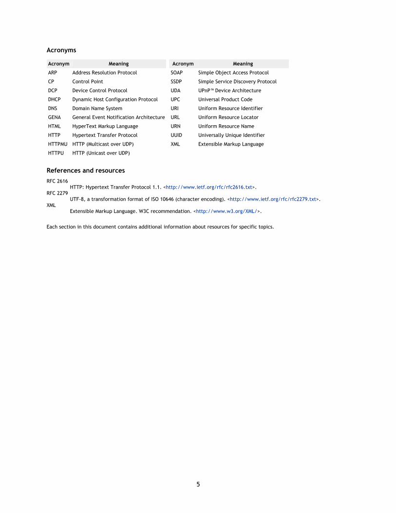
Acronyms
Acronym Meaning
ARP Address Resolution Protocol
CP Control Point
DCP Device Control Protocol
DHCP Dynamic Host Configuration Protocol
DNS Domain Name System
GENA General Event Notification Architecture
HTML HyperText Markup Language
HTTP Hypertext Transfer Protocol
HTTPMU HTTP (Multicast over UDP)
HTTPU HTTP (Unicast over UDP)
Acronym Meaning
SOAP Simple Object Access Protocol
SSDP Simple Service Discovery Protocol
UDA UPnP™ Device Architecture
UPC Universal Product Code
URI Uniform Resource Identifier
URL Uniform Resource Locator
URN Uniform Resource Name
UUID Universally Unique Identifier
XML Extensible Markup Language
References and resources
RFC 2616 HTTP: Hypertext Transfer Protocol 1.1. <http://www.ietf.org/rfc/rfc2616.txt>.
RFC 2279 UTF-8, a transformation format of ISO 10646 (character encoding). <http://www.ietf.org/rfc/rfc2279.txt>.
XML Extensible Markup Language. W3C recommendation. <http://www.w3.org/XML/>.
Each section in this document contains additional information about resources for specific topics.
6
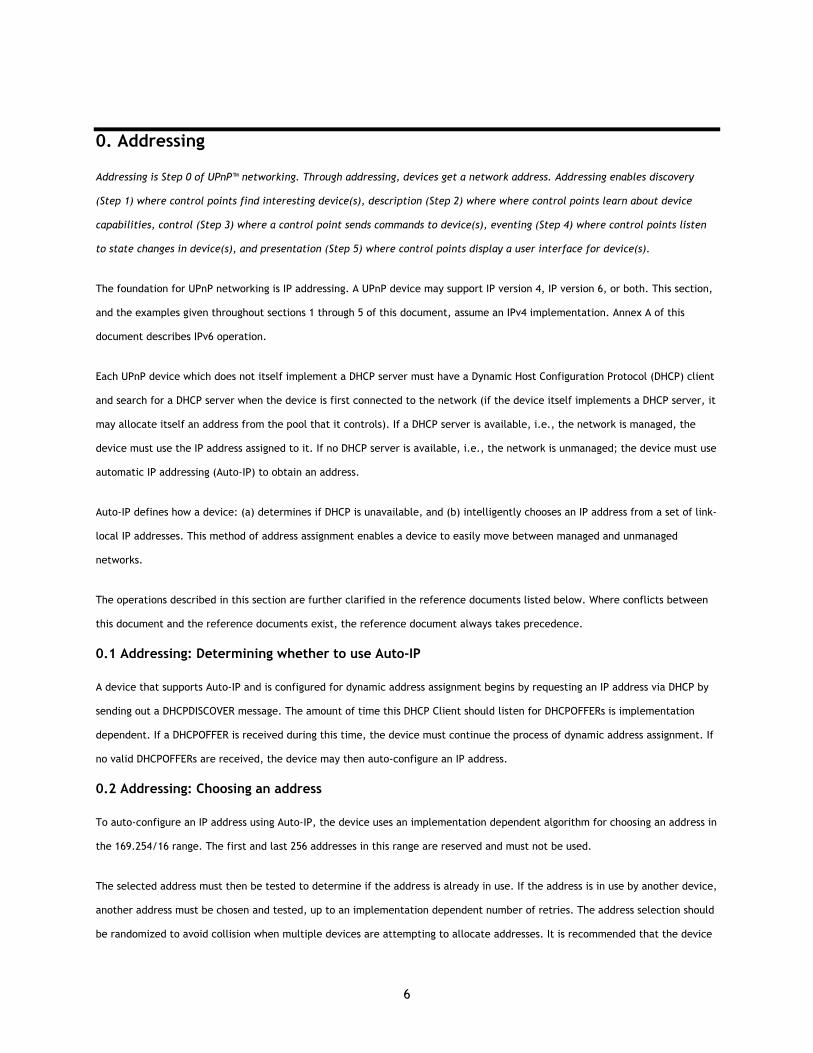
0. Addressing
Addressing is Step 0 of UPnP™ networking. Through addressing, devices get a network address. Addressing enables discovery
(Step 1) where control points find interesting device(s), description (Step 2) where where control points learn about device
capabilities, control (Step 3) where a control point sends commands to device(s), eventing (Step 4) where control points listen
to state changes in device(s), and presentation (Step 5) where control points display a user interface for device(s).
The foundation for UPnP networking is IP addressing. A UPnP device may support IP version 4, IP version 6, or both. This section,
and the examples given throughout sections 1 through 5 of this document, assume an IPv4 implementation. Annex A of this
document describes IPv6 operation.
Each UPnP device which does not itself implement a DHCP server must have a Dynamic Host Configuration Protocol (DHCP) client
and search for a DHCP server when the device is first connected to the network (if the device itself implements a DHCP server, it
may allocate itself an address from the pool that it controls). If a DHCP server is available, i.e., the network is managed, the
device must use the IP address assigned to it. If no DHCP server is available, i.e., the network is unmanaged; the device must use
automatic IP addressing (Auto-IP) to obtain an address.
Auto-IP defines how a device: (a) determines if DHCP is unavailable, and (b) intelligently chooses an IP address from a set of link-
local IP addresses. This method of address assignment enables a device to easily move between managed and unmanaged
networks.
The operations described in this section are further clarified in the reference documents listed below. Where conflicts between
this document and the reference documents exist, the reference document always takes precedence.
0.1 Addressing: Determining whether to use Auto-IP
A device that supports Auto-IP and is configured for dynamic address assignment begins by requesting an IP address via DHCP by
sending out a DHCPDISCOVER message. The amount of time this DHCP Client should listen for DHCPOFFERs is implementation
dependent. If a DHCPOFFER is received during this time, the device must continue the process of dynamic address assignment. If
no valid DHCPOFFERs are received, the device may then auto-configure an IP address.
0.2 Addressing: Choosing an address
To auto-configure an IP address using Auto-IP, the device uses an implementation dependent algorithm for choosing an address in
the 169.254/16 range. The first and last 256 addresses in this range are reserved and must not be used.
The selected address must then be tested to determine if the address is already in use. If the address is in use by another device,
another address must be chosen and tested, up to an implementation dependent number of retries. The address selection should
be randomized to avoid collision when multiple devices are attempting to allocate addresses. It is recommended that the device
7
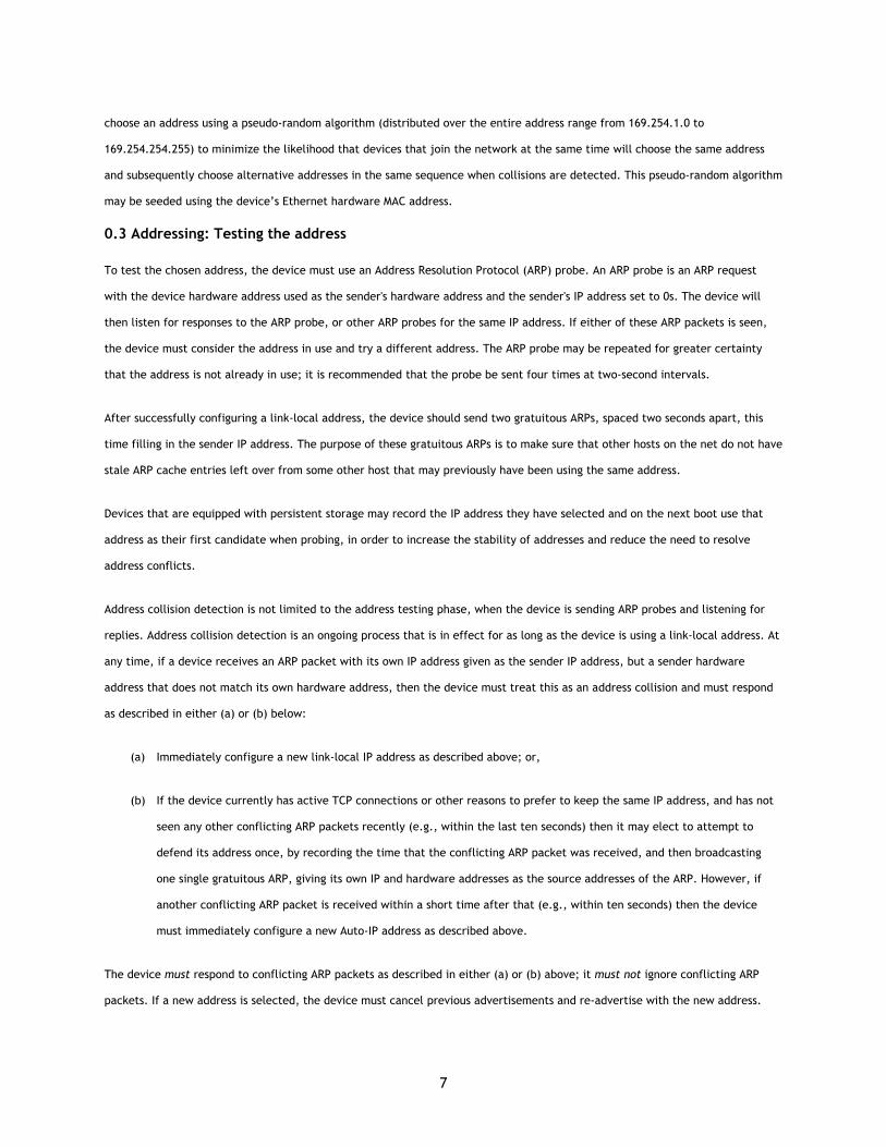
choose an address using a pseudo-random algorithm (distributed over the entire address range from 169.254.1.0 to
169.254.254.255) to minimize the likelihood that devices that join the network at the same time will choose the same address
and subsequently choose alternative addresses in the same sequence when collisions are detected. This pseudo-random algorithm
may be seeded using the device’s Ethernet hardware MAC address.
0.3 Addressing: Testing the address
To test the chosen address, the device must use an Address Resolution Protocol (ARP) probe. An ARP probe is an ARP request
with the device hardware address used as the sender's hardware address and the sender's IP address set to 0s. The device will
then listen for responses to the ARP probe, or other ARP probes for the same IP address. If either of these ARP packets is seen,
the device must consider the address in use and try a different address. The ARP probe may be repeated for greater certainty
that the address is not already in use; it is recommended that the probe be sent four times at two-second intervals.
After successfully configuring a link-local address, the device should send two gratuitous ARPs, spaced two seconds apart, this
time filling in the sender IP address. The purpose of these gratuitous ARPs is to make sure that other hosts on the net do not have
stale ARP cache entries left over from some other host that may previously have been using the same address.
Devices that are equipped with persistent storage may record the IP address they have selected and on the next boot use that
address as their first candidate when probing, in order to increase the stability of addresses and reduce the need to resolve
address conflicts.
Address collision detection is not limited to the address testing phase, when the device is sending ARP probes and listening for
replies. Address collision detection is an ongoing process that is in effect for as long as the device is using a link-local address. At
any time, if a device receives an ARP packet with its own IP address given as the sender IP address, but a sender hardware
address that does not match its own hardware address, then the device must treat this as an address collision and must respond
as described in either (a) or (b) below:
(a) Immediately configure a new link-local IP address as described above; or,
(b) If the device currently has active TCP connections or other reasons to prefer to keep the same IP address, and has not
seen any other conflicting ARP packets recently (e.g., within the last ten seconds) then it may elect to attempt to
defend its address once, by recording the time that the conflicting ARP packet was received, and then broadcasting
one single gratuitous ARP, giving its own IP and hardware addresses as the source addresses of the ARP. However, if
another conflicting ARP packet is received within a short time after that (e.g., within ten seconds) then the device
must immediately configure a new Auto-IP address as described above.
The device must respond to conflicting ARP packets as described in either (a) or (b) above; it must not ignore conflicting ARP
packets. If a new address is selected, the device must cancel previous advertisements and re-advertise with the new address.
8
After successfully configuring an Auto-IP address, all subsequent ARP packets (replies as well as requests) containing an Auto-IP
source address should be sent using link-level broadcast instead of link-level unicast, in order to facilitate timely detection of
duplicate addresses. As an alternative, a device which cannot send broadcast ARP replies should send a unicast ARP reply but
then neglect to follow the instructions in RFC 826 about recording sender information from received ARP requests. This means
that, having failed to record the sender information, the device is likely to send a broadcast ARP request of its own shortly later,
which allows another device using the same IP address to detect the conflict and respond to it.
IP packets whose source or destination addresses are in the 169.254/16 range must not be sent to any router for forwarding. IP
datagrams with a multicast destination address and an Auto-IP source address should not be forwarded off the local link. Devices
and control points may assume that all 169.254/16 destination addresses are on-link and directly reachable. The 169.254/16
address range MUST NOT be subnetted.
Devices which support multiple network interfaces must use different Auto-IP addresses on each interface, and insure that each
address is unique across all interfaces in order to avoid ambiguity as to which interface to use for a particular address. When
such a multi-homed device receives an ARP packet on a particular interface with a source IP address equal to one its addresses,
it should be silently discarded and not considered a collision if the source hardware address matches the hardware address of any
of the its active interfaces.
0.4 Addressing: Periodic checking for dynamic address availability
A device that has auto-configured an IP address must periodically check for the existence of a DHCP server. This is accomplished
by sending DHCPDISCOVER messages. How often this check is made is implementation dependent, but checking every 5 minutes
would maintain a balance between network bandwidth required and connectivity maintenance. If a DHCPOFFER is received, the
device must proceed with dynamic address allocation. Once a DHCP assigned address is in place, the device may release the
auto-configured address, but may also choose to maintain this address for a period of time (or indefinitely) to maintain
connectivity. Devices which support multiple IPv4 addresses may use the NLS header defined in Annex A of this document to
allow compatible control points to recognize that advertisements received from multiple addresses represent the same device.
To switch over from one IP address to a new one, the device should, if possible, cancel any outstanding advertisements made on
the previous address and reissue new advertisements on the new address. The section on Discovery explains advertisements and
their cancellations.
0.5 Addressing: Device naming and DNS interaction
Once a device has a valid IP address for the network, it can be located and referenced on that network through that address.
There may be situations where the end user needs to locate and identify a device. In these situations, a friendly name for the
device is much easier for a human to use than an IP address. If a UPnP device chooses to provide a host name to a DHCP server
and register with a DNS server, the device must either ensure the requested host name is unique or provide a means for the user
9
to change the requested host name. Most often, UPnP devices do not provide a host name, but provide URLs using literal
(numeric) IP addresses.
Moreover, names are much more static than IP addresses. Clients referring a device by name don't require any modification when
the IP address of a device changes. Mapping of the device's DNS name to its IP address could be entered into DNS database
manually or dynamically according to RFC 2136. While devices supporting dynamic DNS updates can register their DNS records
directly in DNS, it is also possible to configure a DHCP server to register DNS records on behalf of these DHCP clients.
0.6 Addressing: Name to IP address resolution
A device that needs to contact another device identified by a DNS name needs to discover its IP address. The device submits a
DNS query according to RFC1034 and 1035 to the pre-configured DNS server(s) and receives a response from a DNS server
containing the IP address of the target device. A device can be statically pre-configured with the list of DNS servers.
Alternatively a device could be configured with the list of DNS server through DHCP, or after the address assignment through a
DHCPINFORM message.
0.7 Addressing references
RFC1034 Domain Names - Concepts and Facilities. <http://www.ietf.org/rfc/rfc1034.txt>.
RFC1035 Domain Names - Implementation and Specification. <http://www.ietf.org/rfc/rfc1035.txt>.
RFC 2131 Dynamic Host Configuration Protocol. <http://www.ietf.org/rfc/rfc2131.txt>.
RFC 2136 Dynamic Updates in the Domain Name System. <http://www.ietf.org/rfc/rfc2136.txt>.
10
1. Discovery
Discovery is Step 1 in UPnP™ networking. Discovery comes after addressing (Step 0) where devices get a network address.
Through discovery, control points find interesting device(s). Discovery enables description (Step 2) where control points learn
about device capabilities, control (Step 3) where a control point sends commands to device(s), eventing (Step 4) where control
points listen to state changes in device(s), and presentation (Step 5) where control points display a user interface for device(s).
Discovery is the first step in UPnP networking. When a device is added to the network, the UPnP discovery protocol allows that
device to advertise its services to control points on the network. Similarly, when a control point is added to the network, the
UPnP discovery protocol allows that control point to search for devices of interest on the network. The fundamental exchange in
both cases is a discovery message containing a few, essential specifics about the device or one of its services, e.g., its type,
universally unique identifier, and a pointer to more detailed information.
11
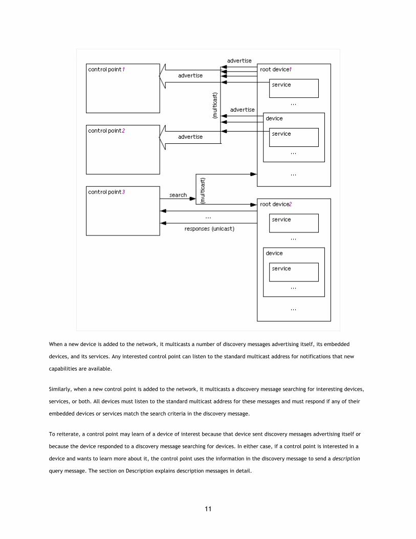
When a new device is added to the network, it multicasts a number of discovery messages advertising itself, its embedded
devices, and its services. Any interested control point can listen to the standard multicast address for notifications that new
capabilities are available.
Similarly, when a new control point is added to the network, it multicasts a discovery message searching for interesting devices,
services, or both. All devices must listen to the standard multicast address for these messages and must respond if any of their
embedded devices or services match the search criteria in the discovery message.
To reiterate, a control point may learn of a device of interest because that device sent discovery messages advertising itself or
because the device responded to a discovery message searching for devices. In either case, if a control point is interested in a
device and wants to learn more about it, the control point uses the information in the discovery message to send a description
query message. The section on Description explains description messages in detail.
12
When a device is removed from the network, it should, if possible, multicast a number of discovery messages revoking its earlier
announcements, effectively declaring that its embedded devices and services will no longer be available. When the IP address of
a device is changed, it should revoke any earlier announcements and advertise using the new IP address.
For devices and control points that have multiple network interfaces, UPnP advertisements and searches should be sent on all
internal network interfaces enabled for UPnP networking. Each advertisement or search must specify an address in the LOCATION
header that is reachable on that interface. UPnP advertisements and searches must not be sent on external Internet interfaces.
To limit network congestion, the time-to-live (TTL) of each IP packet for each multicast message should default to 4 and should
be configurable. When the TTL is greater than 1, it is possible for multicast messages to traverse multiple routers; therefore
control points and devices using DHCP-assigned addresses must send an IGMP Join message so that routers will forward multicast
messages to them (this is not necessary when using an Auto-IP address, since packets with Auto-IP addresses will not be
forwarded by routers).
Discovery plays an important role in the interoperability of devices and control points using different versions of UPnP networking.
The UPnP Device Architecture (defined herein) is versioned with both a major and a minor version, usually written as
major.minor, where both major and minor are integers (for example, version 2.10 [two dot ten] is newer than version 2.2 [two
dot two]). Advances in minor versions must be a compatible superset of earlier minor versions of the same major version.
Advances in major version are not required to be supersets of earlier versions and are not guaranteed to be backward compatible.
Version information is communicated in discovery and description messages. In the former, each discovery message includes the
version of UPnP networking that the device supports (in the SERVER header); the version of device and service types supported is
also included in relevant discovery messages. As a backup, the latter also includes the same information. This section explains
the format of version information in discovery messages and specific requirements on discovery messages to maintain
compatibility with advances in minor versions.
The remainder of this section explains the UPnP discovery protocol known as SSDP (Simple Service Discovery Protocol) in detail,
enumerating how devices advertise and revoke their advertisements as well as how control points search and devices respond.
1.1 Discovery: Advertisement
When a device is added to the network, the device advertises its services to control points. It does this by multicasting discovery
messages to a standard address and port (239.255.255.250:1900). Control points listen to this port to detect when new
capabilities are available on the network. To advertise the full extent of its capabilities, a device multicasts a number of
discovery messages corresponding to each of its embedded devices and services. Each message contains information specific to
the embedded device (or service) as well as information about its enclosing device. Messages should include duration until the
advertisements expire; if the device remains available, the advertisements should be re-sent (with new duration). If the device
becomes unavailable, the device should explicitly cancel its advertisements, but if the device is unable to do this, the
advertisements will expire on their own.
13
1.1.1 Discovery: Advertisement protocols and standards
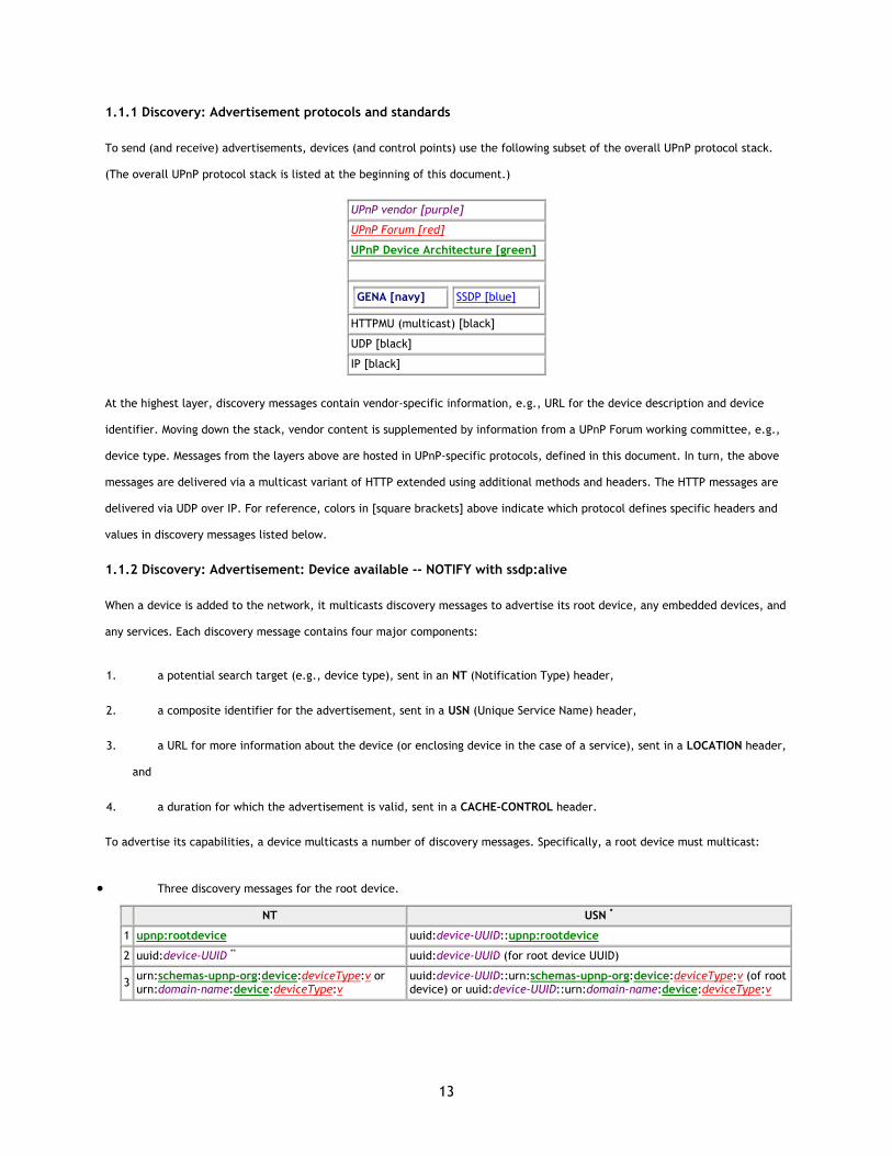
To send (and receive) advertisements, devices (and control points) use the following subset of the overall UPnP protocol stack.
(The overall UPnP protocol stack is listed at the beginning of this document.)
UPnP vendor [purple]
UPnP Forum [red]
UPnP Device Architecture [green]
GENA [navy]
SSDP [blue]
HTTPMU (multicast) [black]
UDP [black]
IP [black]
At the highest layer, discovery messages contain vendor-specific information, e.g., URL for the device description and device
identifier. Moving down the stack, vendor content is supplemented by information from a UPnP Forum working committee, e.g.,
device type. Messages from the layers above are hosted in UPnP-specific protocols, defined in this document. In turn, the above
messages are delivered via a multicast variant of HTTP extended using additional methods and headers. The HTTP messages are
delivered via UDP over IP. For reference, colors in [square brackets] above indicate which protocol defines specific headers and
values in discovery messages listed below.
1.1.2 Discovery: Advertisement: Device available -- NOTIFY with ssdp:alive
When a device is added to the network, it multicasts discovery messages to advertise its root device, any embedded devices, and
any services. Each discovery message contains four major components:
1. a potential search target (e.g., device type), sent in an NT (Notification Type) header,
2. a composite identifier for the advertisement, sent in a USN (Unique Service Name) header,
3. a URL for more information about the device (or enclosing device in the case of a service), sent in a LOCATION header,
and
4. a duration for which the advertisement is valid, sent in a CACHE-CONTROL header.
To advertise its capabilities, a device multicasts a number of discovery messages. Specifically, a root device must multicast:
• Three discovery messages for the root device.
NT USN *
1 upnp:rootdevice uuid:device-UUID::upnp:rootdevice
2 uuid:device-UUID ** uuid:device-UUID (for root device UUID)
3 urn:schemas-upnp-org:device:deviceType:v or urn:domain-name:device:deviceType:v
uuid:device-UUID::urn:schemas-upnp-org:device:deviceType:v (of root device) or uuid:device-UUID::urn:domain-name:device:deviceType:v
14
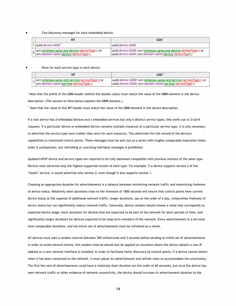
• Two discovery messages for each embedded device.
NT USN *
1 uuid:device-UUID ** uuid:device-UUID
2 urn:schemas-upnp-org:device:deviceType:v or urn:domain-name:device:deviceType:v
uuid:device-UUID::urn:schemas-upnp-org:device:deviceType:v or uuid:device-UUID::urn:domain-name:device:deviceType:v
• Once for each service type in each device.
NT USN *
1 urn:schemas-upnp-org:service:serviceType:v or urn:domain-name:service:serviceType:v
uuid:device-UUID::urn:schemas-upnp-org:service:serviceType:v or uuid:device-UUID::urn:domain-name:service:serviceType:v
* Note that the prefix of the USN header (before the double colon) must match the value of the UDN element in the device
description. (The section on Description explains the UDN element.)
** Note that the value of this NT header must match the value of the UDN element in the device description.
If a root device has d embedded devices and s embedded services but only k distinct service types, this works out to 3+2d+k
requests. If a particular device or embedded device contains multiple instances of a particular service type, it is only necessary
to advertise the service type once (rather than once for each instance). This advertises the full extend of the device's
capabilities to interested control points. These messages must be sent out as a series with roughly comparable expiration times;
order is unimportant, but refreshing or canceling individual messages is prohibited.
Updated UPnP device and service types are required to be fully backward compatible with previous versions of the same type.
Devices must advertise only the highest-supported version of each type. For example, if a device supports version 2 of the
“Audio” service, it would advertise only version 2, even though it also supports version 1.
Choosing an appropriate duration for advertisements is a balance between minimizing network traffic and maximizing freshness
of device status. Relatively short durations close to the minimum of 1800 seconds will ensure that control points have current
device status at the expense of additional network traffic; longer durations, say on the order of a day, compromise freshness of
device status but can significantly reduce network traffic. Generally, device vendors should choose a value that corresponds to
expected device usage: short durations for devices that are expected to be part of the network for short periods of time, and
significantly longer durations for devices expected to be long-term members of the network. Every advertisement in a set must
have comparable durations, and the entire set of advertisements must be refreshed as a whole.
All devices must wait a random interval between 300 milliseconds and 3 seconds before sending an initial set of advertisements
in order to avoid network storms; this random interval should also be applied on occasions where the device obtains a new IP
address or a new network interface is installed. In order to facilitate faster discovery by control points, if a device cannot detect
when it has been connected to the network, it must adjust its advertisement and refresh rates to accommodate the uncertainty.
The first few sets of advertisements could have a relatively short duration (on the order of 60 seconds), but once the device has
seen network traffic or other evidence of network connectivity, the device should increase its advertisement duration to the

15
recommended minimum of 1800 seconds. Devices that frequently connect to and leave the network (such as mobile wireless
devices) may continue to use a shorter duration so that control points have a more accurate view of their availability.
Due to the unreliable nature of UDP, devices should send each of the above discovery messages more than once, although to
avoid network congestion discovery messages should not be sent more than three times. In addition, the device must re-send its
advertisements periodically prior to expiration of the duration specified in the CACHE-CONTROL header; it is recommended that
such refreshing of advertisements be done at a randomly-distributed interval of one-fourth to one-half of the advertisement
expiration time, so as to provide the opportunity for recovery from lost advertisements before the advertisement expires, and to
distribute over time the advertisement refreshment of multiple devices on the network in order to avoid spikes in network traffic.
Note that UDP packets are also bounded in length (perhaps as small as 512 Bytes in some implementations); each discovery
message must fit entirely in a single UDP packet. There is no guarantee that the above 3+2d+k messages will arrive in a particular
order.
When a device is added to the network, it must send a multicast request with method NOTIFY and ssdp:alive in the NTS header
in the following format. Values in italics are placeholders for actual values.
NOTIFY * HTTP/1.1 HOST: 239.255.255.250:1900 CACHE-CONTROL: max-age = seconds until advertisement expires LOCATION: URL for UPnP description for root device NT: search target NTS: ssdp:alive SERVER: OS/version UPnP/1.0 product/version USN: advertisement UUID
(No body for request with method NOTIFY, but note that the message must have a blank line following the last HTTP header.)
The TTL for the IP packet should default to 4 and should be configurable.
Listed below are details for the request line and headers appearing in the listing above. All header values are case sensitive
except where noted.
Request line
NOTIFY Method for sending notifications and events.
* Request applies generally and not to a specific resource. Must be *.
HTTP/1.1 HTTP version.
Headers
HOST Required. Multicast channel and port reserved for SSDP by Internet Assigned Numbers Authority (IANA). Must be 239.255.255.250:1900. If the port number (“:1900”) is omitted, the receiver should assume the default SSDP port number of 1900.
CACHE-CONTROL
16
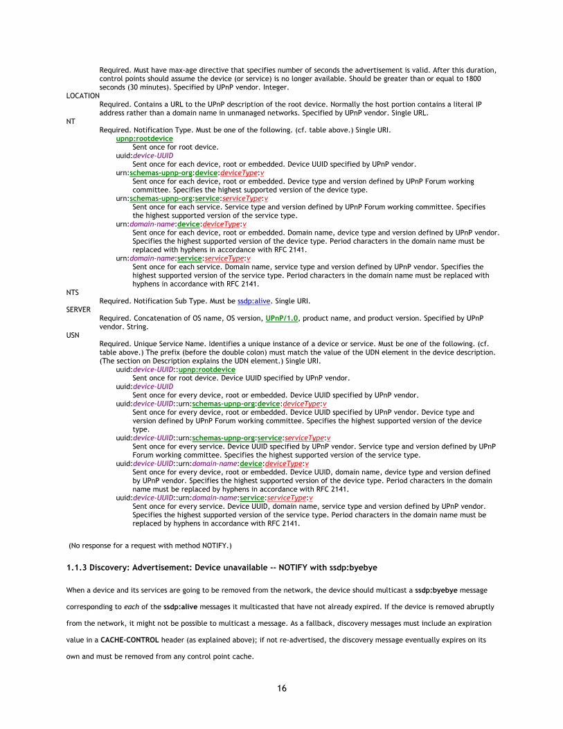
Required. Must have max-age directive that specifies number of seconds the advertisement is valid. After this duration, control points should assume the device (or service) is no longer available. Should be greater than or equal to 1800 seconds (30 minutes). Specified by UPnP vendor. Integer.
LOCATION Required. Contains a URL to the UPnP description of the root device. Normally the host portion contains a literal IP address rather than a domain name in unmanaged networks. Specified by UPnP vendor. Single URL.
NT Required. Notification Type. Must be one of the following. (cf. table above.) Single URI.
upnp:rootdevice Sent once for root device.
uuid:device-UUID Sent once for each device, root or embedded. Device UUID specified by UPnP vendor.
urn:schemas-upnp-org:device:deviceType:v Sent once for each device, root or embedded. Device type and version defined by UPnP Forum working committee. Specifies the highest supported version of the device type.
urn:schemas-upnp-org:service:serviceType:v Sent once for each service. Service type and version defined by UPnP Forum working committee. Specifies the highest supported version of the service type.
urn:domain-name:device:deviceType:v Sent once for each device, root or embedded. Domain name, device type and version defined by UPnP vendor. Specifies the highest supported version of the device type. Period characters in the domain name must be replaced with hyphens in accordance with RFC 2141.
urn:domain-name:service:serviceType:v Sent once for each service. Domain name, service type and version defined by UPnP vendor. Specifies the highest supported version of the service type. Period characters in the domain name must be replaced with hyphens in accordance with RFC 2141.
NTS Required. Notification Sub Type. Must be ssdp:alive. Single URI.
SERVER Required. Concatenation of OS name, OS version, UPnP/1.0, product name, and product version. Specified by UPnP vendor. String.
USN Required. Unique Service Name. Identifies a unique instance of a device or service. Must be one of the following. (cf. table above.) The prefix (before the double colon) must match the value of the UDN element in the device description. (The section on Description explains the UDN element.) Single URI.
uuid:device-UUID::upnp:rootdevice Sent once for root device. Device UUID specified by UPnP vendor.
uuid:device-UUID Sent once for every device, root or embedded. Device UUID specified by UPnP vendor.
uuid:device-UUID::urn:schemas-upnp-org:device:deviceType:v Sent once for every device, root or embedded. Device UUID specified by UPnP vendor. Device type and version defined by UPnP Forum working committee. Specifies the highest supported version of the device type.
uuid:device-UUID::urn:schemas-upnp-org:service:serviceType:v Sent once for every service. Device UUID specified by UPnP vendor. Service type and version defined by UPnP Forum working committee. Specifies the highest supported version of the service type.
uuid:device-UUID::urn:domain-name:device:deviceType:v Sent once for every device, root or embedded. Device UUID, domain name, device type and version defined by UPnP vendor. Specifies the highest supported version of the device type. Period characters in the domain name must be replaced by hyphens in accordance with RFC 2141.
uuid:device-UUID::urn:domain-name:service:serviceType:v Sent once for every service. Device UUID, domain name, service type and version defined by UPnP vendor. Specifies the highest supported version of the service type. Period characters in the domain name must be replaced by hyphens in accordance with RFC 2141.
(No response for a request with method NOTIFY.)
1.1.3 Discovery: Advertisement: Device unavailable -- NOTIFY with ssdp:byebye
When a device and its services are going to be removed from the network, the device should multicast a ssdp:byebye message
corresponding to each of the ssdp:alive messages it multicasted that have not already expired. If the device is removed abruptly
from the network, it might not be possible to multicast a message. As a fallback, discovery messages must include an expiration
value in a CACHE-CONTROL header (as explained above); if not re-advertised, the discovery message eventually expires on its
own and must be removed from any control point cache.
17
(Note: when a control point is about to be removed from the network, no discovery-related action is required.)
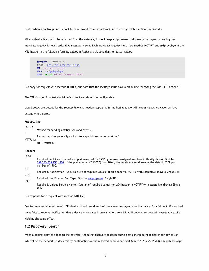
When a device is about to be removed from the network, it should explicitly revoke its discovery messages by sending one
multicast request for each ssdp:alive message it sent. Each multicast request must have method NOTIFY and ssdp:byebye in the
NTS header in the following format. Values in italics are placeholders for actual values.
NOTIFY * HTTP/1.1 HOST: 239.255.255.250:1900 NT: search target NTS: ssdp:byebye USN: uuid:advertisement UUID
(No body for request with method NOTIFY, but note that the message must have a blank line following the last HTTP header.)
The TTL for the IP packet should default to 4 and should be configurable.
Listed below are details for the request line and headers appearing in the listing above. All header values are case sensitive
except where noted.
Request line
NOTIFY Method for sending notifications and events.
* Request applies generally and not to a specific resource. Must be *.
HTTP/1.1 HTTP version.
Headers
HOST Required. Multicast channel and port reserved for SSDP by Internet Assigned Numbers Authority (IANA). Must be 239.255.255.250:1900. If the port number (“:1900”) is omitted, the receiver should assume the default SSDP port number of 1900.
NT Required. Notification Type. (See list of required values for NT header in NOTIFY with ssdp:alive above.) Single URI.
NTS Required. Notification Sub Type. Must be ssdp:byebye. Single URI.
USN Required. Unique Service Name. (See list of required values for USN header in NOTIFY with ssdp:alive above.) Single URI.
(No response for a request with method NOTIFY.)
Due to the unreliable nature of UDP, devices should send each of the above messages more than once. As a fallback, if a control
point fails to receive notification that a device or services is unavailable, the original discovery message will eventually expire
yielding the same effect.
1.2 Discovery: Search
When a control point is added to the network, the UPnP discovery protocol allows that control point to search for devices of
interest on the network. It does this by multicasting on the reserved address and port (239.255.255.250:1900) a search message

18
with a pattern, or target, equal to (or a prefix of) a type or identifier for a device or service. Responses from devices contain
discovery messages essentially identical to those advertised by newly connected devices; the former are unicast while the latter
are multicast.
1.2.1 Discovery: Search protocols and standards
To search for devices (and be discovered by control points), control points (and devices) use the following subset of the overall
UPnP protocol stack. (The overall UPnP protocol stack is listed at the beginning of this document.)
UPnP vendor [purple]
UPnP Forum [red]
UPnP Device Architecture [green]
SSDP [blue]
HTTPU (unicast) [black] HTTPMU (multicast) [black]
UDP [black]
IP [black]
At the highest layer, search messages contain vendor-specific information, e.g., the control point, device, and service identifiers.
Moving down the stack, vendor content is supplemented by information from a UPnP Forum working committee, e.g., device or
service types. Messages from the layers above are hosted in UPnP-specific protocols, defined in this document. In turn, search
requests are delivered via a multicast variant of HTTP that has been extended using additional methods and headers. Search
responses are delivered via a unicast variant of HTTP that has also been extended. Both kinds of HTTP messages are delivered via
UDP over IP. For reference, colors in [square brackets] above indicate which protocol defines specific headers and values in
discovery messages listed below.
1.2.2 Discovery: Search: Request with M-SEARCH
When a control point is added to the network, it should send a multicast request with method M-SEARCH in the following format
(the “M-” prefix indicates the request is a “mandatory” request within the HTTP Extension Framework). Values in italics are
placeholders for actual values.
M-SEARCH * HTTP/1.1 HOST: 239.255.255.250:1900 MAN: "ssdp:discover" MX: seconds to delay response ST: search target
(No body for request with method M-SEARCH, but note that the message must have a blank line following the last HTTP header.)
The TTL for the IP packet should default to 4 and should be configurable.
Note that it is also permitted to send the M-SEARCH request using unicast UDP to the same port, if the address of the targeted
device is already known.
19
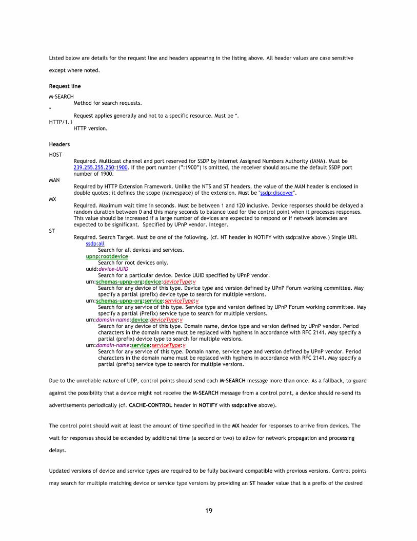
Listed below are details for the request line and headers appearing in the listing above. All header values are case sensitive
except where noted.
Request line
M-SEARCH Method for search requests.
* Request applies generally and not to a specific resource. Must be *.
HTTP/1.1 HTTP version.
Headers
HOST Required. Multicast channel and port reserved for SSDP by Internet Assigned Numbers Authority (IANA). Must be 239.255.255.250:1900. If the port number (“:1900”) is omitted, the receiver should assume the default SSDP port number of 1900.
MAN Required by HTTP Extension Framework. Unlike the NTS and ST headers, the value of the MAN header is enclosed in double quotes; it defines the scope (namespace) of the extension. Must be "ssdp:discover".
MX Required. Maximum wait time in seconds. Must be between 1 and 120 inclusive. Device responses should be delayed a random duration between 0 and this many seconds to balance load for the control point when it processes responses. This value should be increased if a large number of devices are expected to respond or if network latencies are expected to be significant. Specified by UPnP vendor. Integer.
ST Required. Search Target. Must be one of the following. (cf. NT header in NOTIFY with ssdp:alive above.) Single URI.
ssdp:all Search for all devices and services.
upnp:rootdevice Search for root devices only.
uuid:device-UUID Search for a particular device. Device UUID specified by UPnP vendor.
urn:schemas-upnp-org:device:deviceType:v Search for any device of this type. Device type and version defined by UPnP Forum working committee. May specify a partial (prefix) device type to search for multiple versions.
urn:schemas-upnp-org:service:serviceType:v Search for any service of this type. Service type and version defined by UPnP Forum working committee. May specify a partial (Prefix) service type to search for multiple versions.
urn:domain-name:device:deviceType:v Search for any device of this type. Domain name, device type and version defined by UPnP vendor. Period characters in the domain name must be replaced with hyphens in accordance with RFC 2141. May specify a partial (prefix) device type to search for multiple versions.
urn:domain-name:service:serviceType:v Search for any service of this type. Domain name, service type and version defined by UPnP vendor. Period characters in the domain name must be replaced with hyphens in accordance with RFC 2141. May specify a partial (prefix) service type to search for multiple versions.
Due to the unreliable nature of UDP, control points should send each M-SEARCH message more than once. As a fallback, to guard
against the possibility that a device might not receive the M-SEARCH message from a control point, a device should re-send its
advertisements periodically (cf. CACHE-CONTROL header in NOTIFY with ssdp:alive above).
The control point should wait at least the amount of time specified in the MX header for responses to arrive from devices. The
wait for responses should be extended by additional time (a second or two) to allow for network propagation and processing
delays.
Updated versions of device and service types are required to be fully backward compatible with previous versions. Control points
may search for multiple matching device or service type versions by providing an ST header value that is a prefix of the desired
20
matches. For example, if the control point is capable of interoperating with any version of the standard “Audio” service type, it
may search for “urn:schemas-upnp-org:service:Audio:”. Control points should not search for a specific version of a type. No wild
card characters, regular expressions, or formulations other than prefix strings are permitted in the ST header. Including the
trailing colon (“:”) prevents responses from devices with types that match only a portion of the deviceType or serviceType.
Control points must not search for prefixes of “ssdp:all”, “upnp:rootdevice”, or “uuid:”, since all UPnP devices would respond to
such searches.
1.2.3 Discovery: Search: Response
To be found, a device must send a UDP response to the source IP address and port that sent the request to the multicast
channel. Devices respond if the ST header of the M-SEARCH request is “ssdp:all”, “upnp:rootdevice”, “uuid:” followed by a UUID
that exactly matches one advertised by the device, or a prefix of a device or service type supported by the device.
Devices must wait a random period of time between 0 seconds and the number of seconds specified in the MX header of the
search request before responding, in order to avoid flooding the requesting control point with search responses from multiple
devices. If the search request results in the need for multiple responses from the device, those responses should be spread at
random intervals through the time period from 0 to the number of seconds specified in the MX header. If the search request does
not contain an MX header, the device must silently discard and ignore the search request. If the MX header specifies a value
greater than 120, the device should assume that it contained the value 120. Devices should not stop responding to other requests
while waiting the random delay before sending a response.
A multi-homed device (one that supports multiple network interfaces or multiple IP addresses) must respond to a search request
using the same interface and the same address on which the search request was received.
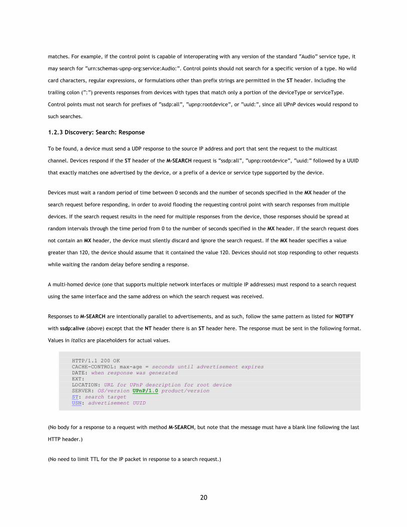
Responses to M-SEARCH are intentionally parallel to advertisements, and as such, follow the same pattern as listed for NOTIFY
with ssdp:alive (above) except that the NT header there is an ST header here. The response must be sent in the following format.
Values in italics are placeholders for actual values.
HTTP/1.1 200 OK CACHE-CONTROL: max-age = seconds until advertisement expires DATE: when response was generated EXT: LOCATION: URL for UPnP description for root device SERVER: OS/version UPnP/1.0 product/version ST: search target USN: advertisement UUID
(No body for a response to a request with method M-SEARCH, but note that the message must have a blank line following the last
HTTP header.)
(No need to limit TTL for the IP packet in response to a search request.)
21
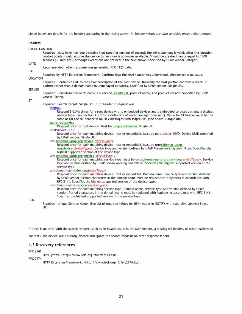
Listed below are details for the headers appearing in the listing above. All header values are case sensitive except where noted.
Headers
CACHE-CONTROL Required. Must have max-age directive that specifies number of seconds the advertisement is valid. After this duration, control points should assume the device (or service) is no longer available. Should be greater than or equal to 1800 seconds (30 minutes), although exceptions are defined in the text above. Specified by UPnP vendor. Integer.
DATE Recommended. When response was generated. RFC 1123 date.
EXT Required by HTTP Extension Framework. Confirms that the MAN header was understood. (Header only; no value.)
LOCATION Required. Contains a URL to the UPnP description of the root device. Normally the host portion contains a literal IP address rather than a domain name in unmanaged networks. Specified by UPnP vendor. Single URL.
SERVER Required. Concatenation of OS name, OS version, UPnP/1.0, product name, and product version. Specified by UPnP vendor. String.
ST Required. Search Target. Single URI. If ST header in request was,
ssdp:all Respond 3+2d+k times for a root device with d embedded devices and s embedded services but only k distinct service types (see section 1.1.2 for a definition of each message to be sent). Value for ST header must be the same as for the NT header in NOTIFY messages with ssdp:alive. (See above.) Single URI.
upnp:rootdevice Respond once for root device. Must be upnp:rootdevice. Single URI.
uuid:device-UUID Respond once for each matching device, root or embedded. Must be uuid:device-UUID. Device UUID specified by UPnP vendor. Single URI.
urn:schemas-upnp-org:device:deviceType:v Respond once for each matching device, root or embedded. Must be urn:schemas-upnp-org:device:deviceType:v. Device type and version defined by UPnP Forum working committee. Specifies the highest supported version of the device type.
urn:schemas-upnp-org:service:serviceType:v Respond once for each matching service type. Must be urn:schemas-upnp-org:service:serviceType:v. Service type and version defined by UPnP Forum working committee. Specifies the highest supported version of the service type.
urn:domain-name:device:deviceType:v Respond once for each matching device, root or embedded. Domain name, device type and version defined by UPnP vendor. Period characters in the domain name must be replaced with hyphens in accordance with RFC 2141. Specifies the highest supported version of the device type.
urn:domain-name:service:serviceType:v Respond once for each matching service type. Domain name, service type and version defined by UPnP vendor. Period characters in the domain name must be replaced with hyphens in accordance with RFC 2141. Specifies the highest supported version of the service type.
USN Required. Unique Service Name. (See list of required values for USN header in NOTIFY with ssdp:alive above.) Single URI.
If there is an error with the search request (such as an invalid value in the MAN header, a missing MX header, or other malformed
content), the device MUST silently discard and ignore the search request; no error response is sent.
1.3 Discovery references
RFC 2141 URN Syntax. <http://www.ietf.org/rfc/rfc2141.txt>.
RFC 2774 HTTP Extension Framework. <http://www.ietf.org/rfc/rfc2774.txt>.
22
2. Description
Description is Step 2 in UPnP™ networking. Description comes after addressing (Step 0) where devices get a network address,
and after discovery (Step 1) where control points find interesting device(s). Description enables control (Step 3) where control
points send commands to device(s), eventing (Step 4) where control points listen to state changes in device(s), and presentation
(Step 5) where control points display a user interface for device(s).
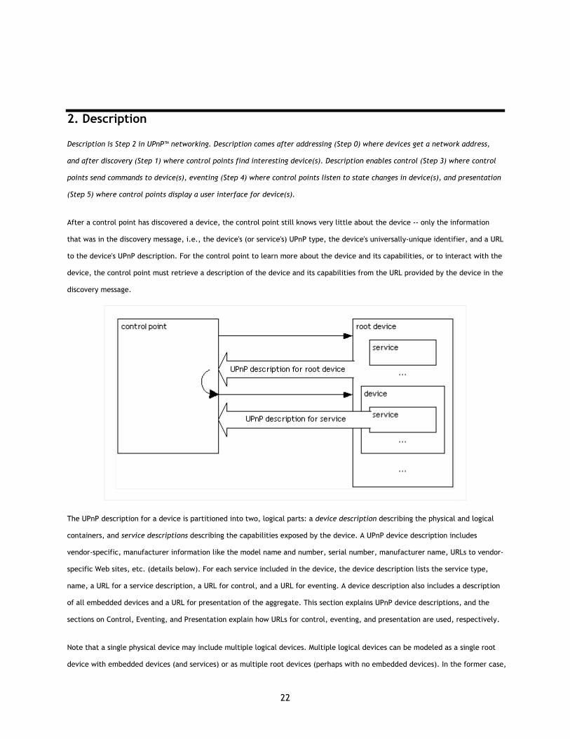
After a control point has discovered a device, the control point still knows very little about the device -- only the information
that was in the discovery message, i.e., the device's (or service's) UPnP type, the device's universally-unique identifier, and a URL
to the device's UPnP description. For the control point to learn more about the device and its capabilities, or to interact with the
device, the control point must retrieve a description of the device and its capabilities from the URL provided by the device in the
discovery message.
The UPnP description for a device is partitioned into two, logical parts: a device description describing the physical and logical
containers, and service descriptions describing the capabilities exposed by the device. A UPnP device description includes
vendor-specific, manufacturer information like the model name and number, serial number, manufacturer name, URLs to vendor-
specific Web sites, etc. (details below). For each service included in the device, the device description lists the service type,
name, a URL for a service description, a URL for control, and a URL for eventing. A device description also includes a description
of all embedded devices and a URL for presentation of the aggregate. This section explains UPnP device descriptions, and the
sections on Control, Eventing, and Presentation explain how URLs for control, eventing, and presentation are used, respectively.
Note that a single physical device may include multiple logical devices. Multiple logical devices can be modeled as a single root
device with embedded devices (and services) or as multiple root devices (perhaps with no embedded devices). In the former case,

23
there is one UPnP device description for the root device, and that device description contains a description for all embedded
devices. In the latter case, there are multiple UPnP device descriptions, one for each root device.
A UPnP device description is written by a UPnP vendor. The description is in XML syntax and is usually based on a standard UPnP
Device Template. A UPnP Device Template is produced by a UPnP Forum working committee; they derive the template from the
UPnP Template Language, which was derived from standard constructions in XML. This section explains the format for a UPnP
device description, UPnP Device Templates, and the part of the UPnP Template Language that covers devices.
A UPnP service description includes a list of commands, or actions, the service responds to, and parameters, or arguments, for
each action. A service description also includes a list of variables. These variables model the state of the service at run time, and
are described in terms of their data type, range, and event characteristics. This section explains the description of actions,
arguments, state variables, and the properties of those variables. The section on Eventing explains event characteristics.
Like a UPnP device description, a UPnP service description is written by a UPnP vendor. The description is in XML syntax and is
usually based on a standard UPnP Service Template. A UPnP Service Template is produced by a UPnP Forum working committee;
they derived the template from the UPnP Template Language, augmenting it with human language where necessary. The UPnP
Template Language is derived from standard constructions in XML. This section explains the format for a UPnP service description,
UPnP Service Templates, typical augmentations in human language, and the part of the UPnP Template Language that covers
services.
UPnP vendors can differentiate their devices by extending services, including additional UPnP services, or embedding additional
devices. When a control point retrieves a particular device's description, these added features are exposed to the control point
for control and eventing. The device and service descriptions authoritatively document the implementation of the device.
Retrieving a UPnP device description is simple: the control point issues an HTTP GET request on the URL in the discovery message,
and the device returns the device description. Retrieving a UPnP service description is a similar process that uses a URL within
the device description. The protocol stack, method, headers, and body for the response and request are explained in detail
below.
As long as the discovery advertisements from a device have not expired, a control point may assume that the device and its
services are available. The device and service descriptions may be retrieved at any point since the device and service
descriptions are static as long as the device and its services are available. If a device cancels its advertisements or if the
advertisements expire, a control point must assume the device and its services are no longer available. If a device needs to
change one of these descriptions, it must cancel its outstanding advertisements and re-advertise. Consequently, control points
should not assume that device and service descriptions are unchanged if a device re-appears on the network.
Like discovery, description plays an important role in the interoperability of devices and control points using different versions of
UPnP networking. As explained in the section on Discovery, The UPnP Device Architecture is versioned with both a major and a

24
minor version. The major version and minor version are separate integer numbers; they are not to be interpreted or compared as
though they were a single decimal number, even though they may appear as such in print. Advances in minor versions must be a
compatible superset of earlier minor versions of the same major version. Advances in major version are not required to be
supersets of earlier versions and are not guaranteed to be backward compatible. Version information is communicated in
description messages as a backup to the information communicated in discovery messages. This section explains the format of
version information in description messages.
Device and service types standardized by UPnP Forum working committees or created by vendors have an integer version. Every
later version of a device or service must be a fully backwardly compatible superset of the previous version, i.e., compared to
earlier versions of the device, it must include all embedded devices and services of the same or later version. The UPnP device or
service type remains the same across all versions of a device whereas the device or service version must be larger for later
versions. Versions of device and service templates may have non-integer versions (such as “0.9”) during development in the
working committee, but this must become an integer upon standardization. Devices and services may have a version number
greater than the major version number of the architecture they are designed for (e.g., “Power:2” may be designed to work on
UDA version 1.0); there is no direct correlation between the version of a device or service template and the architecture version
with which it is designed to work. If an non-backward-compatible version of a device or service is defined, it must have a
different device or service name to indicate that it is not backwardly compatible (and version numbers of the new type should
restart at 1).
The remainder of this section first explains how devices are described, explaining details of vendor-specific information,
embedded devices, and URLs for control, eventing, and presentation. Second, it explains UPnP Device Templates. Third, it
explains how services are described, explaining details of actions, arguments, state variables, and properties of those variables.
Then it explains UPnP Service Templates, and the UPnP Template Language. Finally, this section explains in detail how a control
point retrieves device and service descriptions from a device.
2.1 Description: Device description
The UPnP description for a device contains several pieces of vendor-specific information, definitions of all embedded devices,
URL for presentation of the device, and listings for all services, including URLs for control and eventing. In addition to defining
non-standard devices, UPnP vendors may add embedded devices and services to standard devices. To illustrate these, below is a
listing with placeholders (in italics) for actual elements and values. Some of these placeholders would be specified by a UPnP
Forum working committee (colored red) or by a UPnP vendor (purple). For a non-standard device, all of these placeholders would
be specified by a UPnP vendor. (Elements defined by the UPnP Device Architecture are colored green for later
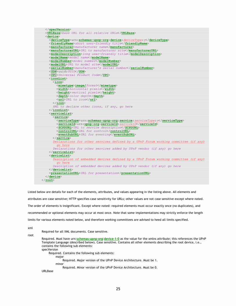
reference.) Immediately following the listing is a detailed explanation of the elements, attributes, and values.
<?xml version="1.0"?> <root xmlns="urn:schemas-upnp-org:device-1-0"> <specVersion> <major>1</major> <minor>0</minor>
25
</specVersion> <URLBase>base URL for all relative URLs</URLBase> <device> <deviceType>urn:schemas-upnp-org:device:deviceType:v</deviceType> <friendlyName>short user-friendly title</friendlyName> <manufacturer>manufacturer name</manufacturer> <manufacturerURL>URL to manufacturer site</manufacturerURL> <modelDescription>long user-friendly title</modelDescription> <modelName>model name</modelName> <modelNumber>model number</modelNumber> <modelURL>URL to model site</modelURL> <serialNumber>manufacturer's serial number</serialNumber> <UDN>uuid:UUID</UDN> <UPC>Universal Product Code</UPC> <iconList> <icon> <mimetype>image/format</mimetype> <width>horizontal pixels</width> <height>vertical pixels</height> <depth>color depth</depth> <url>URL to icon</url> </icon> XML to declare other icons, if any, go here </iconList> <serviceList> <service> <serviceType>urn:schemas-upnp-org:service:serviceType:v</serviceType> <serviceId>urn:upnp-org:serviceId:serviceID</serviceId> <SCPDURL>URL to service description</SCPDURL> <controlURL>URL for control</controlURL> <eventSubURL>URL for eventing</eventSubURL> </service> Declarations for other services defined by a UPnP Forum working committee (if any) go here Declarations for other services added by UPnP vendor (if any) go here </serviceList> <deviceList> Description of embedded devices defined by a UPnP Forum working committee (if any) go here Description of embedded devices added by UPnP vendor (if any) go here </deviceList> <presentationURL>URL for presentation</presentationURL> </device> </root>
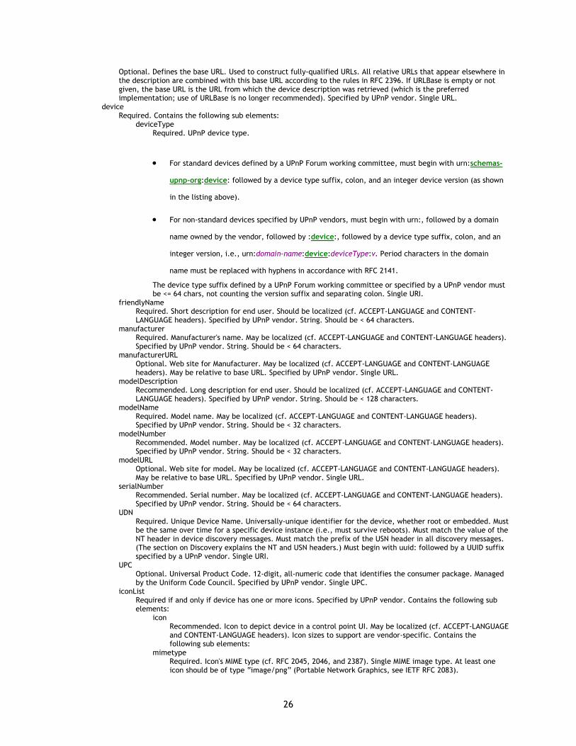
Listed below are details for each of the elements, attributes, and values appearing in the listing above. All elements and
attributes are case sensitive; HTTP specifies case sensitivity for URLs; other values are not case sensitive except where noted.
The order of elements is insignificant. Except where noted: required elements must occur exactly once (no duplicates), and
recommended or optional elements may occur at most once. Note that some implementations may strictly enforce the length
limits for various elements noted below, and therefore working committees are advised to heed all limits specified.
xml Required for all XML documents. Case sensitive.
root Required. Must have urn:schemas-upnp-org:device-1-0 as the value for the xmlns attribute; this references the UPnP Template Language (described below). Case sensitive. Contains all other elements describing the root device, i.e., contains the following sub elements: specVersion
Required. Contains the following sub elements: major
Required. Major version of the UPnP Device Architecture. Must be 1. minor
Required. Minor version of the UPnP Device Architecture. Must be 0. URLBase
26
Optional. Defines the base URL. Used to construct fully-qualified URLs. All relative URLs that appear elsewhere in the description are combined with this base URL according to the rules in RFC 2396. If URLBase is empty or not given, the base URL is the URL from which the device description was retrieved (which is the preferred implementation; use of URLBase is no longer recommended). Specified by UPnP vendor. Single URL.
device Required. Contains the following sub elements:
deviceType Required. UPnP device type.
• For standard devices defined by a UPnP Forum working committee, must begin with urn:schemas-
upnp-org:device: followed by a device type suffix, colon, and an integer device version (as shown
in the listing above).
• For non-standard devices specified by UPnP vendors, must begin with urn:, followed by a domain
name owned by the vendor, followed by :device:, followed by a device type suffix, colon, and an
integer version, i.e., urn:domain-name:device:deviceType:v. Period characters in the domain
name must be replaced with hyphens in accordance with RFC 2141.
The device type suffix defined by a UPnP Forum working committee or specified by a UPnP vendor must be <= 64 chars, not counting the version suffix and separating colon. Single URI.
friendlyName Required. Short description for end user. Should be localized (cf. ACCEPT-LANGUAGE and CONTENT-LANGUAGE headers). Specified by UPnP vendor. String. Should be < 64 characters.
manufacturer Required. Manufacturer's name. May be localized (cf. ACCEPT-LANGUAGE and CONTENT-LANGUAGE headers). Specified by UPnP vendor. String. Should be < 64 characters.
manufacturerURL Optional. Web site for Manufacturer. May be localized (cf. ACCEPT-LANGUAGE and CONTENT-LANGUAGE headers). May be relative to base URL. Specified by UPnP vendor. Single URL.
modelDescription Recommended. Long description for end user. Should be localized (cf. ACCEPT-LANGUAGE and CONTENT-LANGUAGE headers). Specified by UPnP vendor. String. Should be < 128 characters.
modelName Required. Model name. May be localized (cf. ACCEPT-LANGUAGE and CONTENT-LANGUAGE headers). Specified by UPnP vendor. String. Should be < 32 characters.
modelNumber Recommended. Model number. May be localized (cf. ACCEPT-LANGUAGE and CONTENT-LANGUAGE headers). Specified by UPnP vendor. String. Should be < 32 characters.
modelURL Optional. Web site for model. May be localized (cf. ACCEPT-LANGUAGE and CONTENT-LANGUAGE headers). May be relative to base URL. Specified by UPnP vendor. Single URL.
serialNumber Recommended. Serial number. May be localized (cf. ACCEPT-LANGUAGE and CONTENT-LANGUAGE headers). Specified by UPnP vendor. String. Should be < 64 characters.
UDN Required. Unique Device Name. Universally-unique identifier for the device, whether root or embedded. Must be the same over time for a specific device instance (i.e., must survive reboots). Must match the value of the NT header in device discovery messages. Must match the prefix of the USN header in all discovery messages. (The section on Discovery explains the NT and USN headers.) Must begin with uuid: followed by a UUID suffix specified by a UPnP vendor. Single URI.
UPC Optional. Universal Product Code. 12-digit, all-numeric code that identifies the consumer package. Managed by the Uniform Code Council. Specified by UPnP vendor. Single UPC.
iconList Required if and only if device has one or more icons. Specified by UPnP vendor. Contains the following sub elements:
icon Recommended. Icon to depict device in a control point UI. May be localized (cf. ACCEPT-LANGUAGE and CONTENT-LANGUAGE headers). Icon sizes to support are vendor-specific. Contains the following sub elements:
mimetype Required. Icon's MIME type (cf. RFC 2045, 2046, and 2387). Single MIME image type. At least one icon should be of type “image/png” (Portable Network Graphics, see IETF RFC 2083).
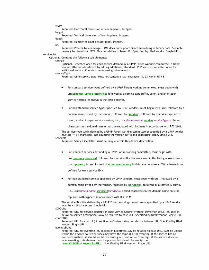
27
width Required. Horizontal dimension of icon in pixels. Integer.
height Required. Vertical dimension of icon in pixels. Integer.
depth Required. Number of color bits per pixel. Integer.
url Required. Pointer to icon image. (XML does not support direct embedding of binary data. See note below.) Retrieved via HTTP. May be relative to base URL. Specified by UPnP vendor. Single URL.
serviceList Optional. Contains the following sub elements:
service Optional. Repeated once for each service defined by a UPnP Forum working committee. If UPnP vendor differentiates device by adding additional, standard UPnP services, repeated once for additional service. Contains the following sub elements:
serviceType Required. UPnP service type. Must not contain a hash character (#, 23 Hex in UTF-8).
• For standard service types defined by a UPnP Forum working committee, must begin with
urn:schemas-upnp-org:service: followed by a service type suffix, colon, and an integer
service version (as shown in the listing above).
• For non-standard service types specified by UPnP vendors, must begin with urn:, followed by a
domain name owned by the vendor, followed by :service:, followed by a service type suffix,
colon, and an integer service version, i.e., urn:domain-name:service:serviceType:v. Period
characters in the domain name must be replaced with hyphens in accordance with RFC 2141.
The service type suffix defined by a UPnP Forum working committee or specified by a UPnP vendor must be <= 64 characters, not counting the version suffix and separating colon. Single URI.
serviceId Required. Service identifier. Must be unique within this device description.
• For standard services defined by a UPnP Forum working committee, must begin with
urn:upnp-org:serviceId: followed by a service ID suffix (as shown in the listing above). (Note
that upnp-org is used instead of schemas-upnp-org in this case because an XML schema is not
defined for each service ID.)
• For non-standard services specified by UPnP vendors, must begin with urn:, followed by a
domain name owned by the vendor, followed by :serviceId:, followed by a service ID suffix,
i.e., urn:domain-name:serviceId:serviceID. Period characters in the domain name must be
replaced with hyphens in accordance with RFC 2141.
The service ID suffix defined by a UPnP Forum working committee or specified by a UPnP vendor must be <= 64 characters. Single URI.
SCPDURL Required. URL for service description (nee Service Control Protocol Definition URL). (cf. section below on service description.) May be relative to base URL. Specified by UPnP vendor. Single URL.
controlURL Required. URL for control (cf. section on Control). May be relative to base URL. Specified by UPnP vendor. Single URL.
eventSubURL Required. URL for eventing (cf. section on Eventing). May be relative to base URL. Must be unique within the device; no two services may have the same URL for eventing. If the service has no evented variables, it should not have eventing (cf. section on Eventing); if the service does not have eventing, this element must be present but should be empty, i.e., <eventSubURL></eventSubURL>. Specified by UPnP vendor. Single URL.

28
deviceList Required if and only if root device has embedded devices. Contains the following sub elements:
device Required. Repeat once for each embedded device defined by a UPnP Forum working committee. If UPnP vendor differentiates device by embedding additional UPnP devices, repeat once for each embedded device. Contains sub elements as defined above for root sub element device.
presentationURL Recommended. URL to presentation for device (cf. section on Presentation). May be relative to base URL. Specified by UPnP vendor. Single URL.
For future extensibility, when processing XML like the listing above, devices and control points must ignore: (a) any unknown
elements and their sub elements or content, and (b) any unknown attributes and their values.
Control points shall ignore any XML comments or XML processing instructions embedded in UPnP device and service descriptions.
Devices shall not send XML comments or XML processing instructions in UPnP device and service descriptions.
UPnP device descriptions shall be encoded using UTF-8. UPnP control points do not need to be capable of decoding XML
documents encoded in UTF-16.
Note that ampersand character (&, 0x26 in UTF-8) is not allowed in XML. If required as part of the value of an XML element (e.g.,
a URL), the ampersand character must be converted into & (HTML) or %26 (URL escape code).
XML does not support directly embedding binary data, e.g., icons in UPnP device descriptions. Binary data may be converted into
text (and thereby embedded into XML) using an XML data type of either bin.base64 (a MIME-style base 64 encoding for binary
data) or bin.hex (hexadecimal digits represent octets). Alternatively, the data can be passed indirectly, as it were, by embedding
a URL in the XML and transferring the data in response to a separate HTTP request; the icon(s) in UPnP device descriptions are
transferred in this latter manner.
If any icons are included, at least one should be in the Portable Network Graphics (PNG) format defined in RFC 2083 and
indicated by the MIME type “image/png”. PNG icons must not be progressively encoded. No specific icon sizes are recommended
due to the wide variety preferred by various control points; control point vendors are encouraged to publish implementation
guidelines.
2.2 Description: UPnP Device Template
The listing above also illustrates the relationship between a UPnP device description and a UPnP Device Template. As explained
above, the UPnP device description is written by a UPnP vendor, in XML, following a UPnP Device Template. A UPnP Device
Template is produced by a UPnP Forum working committee as a means to standardize devices.
By appropriate specification of placeholders, the listing above can be either a UPnP Device Template or a UPnP device
description. Recall that some placeholders would be defined by a UPnP Forum working committee (colored red), i.e., the UPnP
device type identifier, required UPnP services, and required UPnP embedded devices (if any). If these were defined, the listing
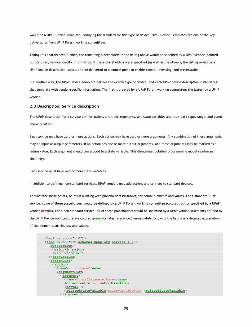
29
would be a UPnP Device Template, codifying the standard for this type of device. UPnP Device Templates are one of the key
deliverables from UPnP Forum working committees.
Taking this another step further, the remaining placeholders in the listing above would be specified by a UPnP vendor (colored
purple), i.e., vendor-specific information. If these placeholders were specified (as well as the others), the listing would be a
UPnP device description, suitable to be delivered to a control point to enable control, eventing, and presentation.
Put another way, the UPnP Device Template defines the overall type of device, and each UPnP device description instantiates
that template with vendor-specific information. The first is created by a UPnP Forum working committee; the latter, by a UPnP
vendor.
2.3 Description: Service description
The UPnP description for a service defines actions and their arguments, and state variables and their data type, range, and event
characteristics.
Each service may have zero or more actions. Each action may have zero or more arguments. Any combination of these arguments
may be input or output parameters. If an action has one or more output arguments, one these arguments may be marked as a
return value. Each argument should correspond to a state variable. This direct-manipulation programming model reinforces
simplicity.
Each service must have one or more state variables.
In addition to defining non-standard services, UPnP vendors may add actions and services to standard devices.
To illustrate these points, below is a listing with placeholders (in italics) for actual elements and values. For a standard UPnP
service, some of these placeholders would be defined by a UPnP Forum working committee (colored red) or specified by a UPnP
vendor (purple). For a non-standard service, all of these placeholders would be specified by a UPnP vendor. (Elements defined by
the UPnP Device Architecture are colored green for later reference.) Immediately following the listing is a detailed explanation
of the elements, attributes, and values.
<?xml version="1.0"?> <scpd xmlns="urn:schemas-upnp-org:service-1-0"> <specVersion> <major>1</major> <minor>0</minor> </specVersion> <actionList> <action> <name>actionName</name> <argumentList> <argument> <name>formalParameterName</name> <direction>in xor out</direction> <retval /> <relatedStateVariable>stateVariableName</relatedStateVariable> </argument>
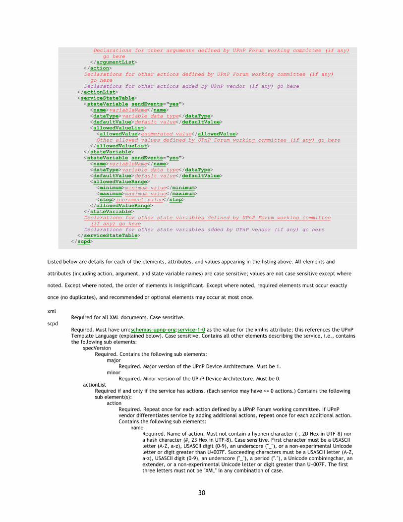
30
Declarations for other arguments defined by UPnP Forum working committee (if any) go here </argumentList> </action> Declarations for other actions defined by UPnP Forum working committee (if any) go here Declarations for other actions added by UPnP vendor (if any) go here </actionList> <serviceStateTable> <stateVariable sendEvents="yes"> <name>variableName</name> <dataType>variable data type</dataType> <defaultValue>default value</defaultValue> <allowedValueList> <allowedValue>enumerated value</allowedValue> Other allowed values defined by UPnP Forum working committee (if any) go here </allowedValueList> </stateVariable> <stateVariable sendEvents="yes"> <name>variableName</name> <dataType>variable data type</dataType> <defaultValue>default value</defaultValue> <allowedValueRange> <minimum>minimum value</minimum> <maximum>maximum value</maximum> <step>increment value</step> </allowedValueRange> </stateVariable> Declarations for other state variables defined by UPnP Forum working committee (if any) go here Declarations for other state variables added by UPnP vendor (if any) go here </serviceStateTable> </scpd>
Listed below are details for each of the elements, attributes, and values appearing in the listing above. All elements and
attributes (including action, argument, and state variable names) are case sensitive; values are not case sensitive except where
noted. Except where noted, the order of elements is insignificant. Except where noted, required elements must occur exactly
once (no duplicates), and recommended or optional elements may occur at most once.
xml Required for all XML documents. Case sensitive.
scpd Required. Must have urn:schemas-upnp-org:service-1-0 as the value for the xmlns attribute; this references the UPnP Template Language (explained below). Case sensitive. Contains all other elements describing the service, i.e., contains the following sub elements:
specVersion Required. Contains the following sub elements:
major Required. Major version of the UPnP Device Architecture. Must be 1.
minor Required. Minor version of the UPnP Device Architecture. Must be 0.
actionList Required if and only if the service has actions. (Each service may have >= 0 actions.) Contains the following sub element(s):
action Required. Repeat once for each action defined by a UPnP Forum working committee. If UPnP vendor differentiates service by adding additional actions, repeat once for each additional action. Contains the following sub elements:
name Required. Name of action. Must not contain a hyphen character (-, 2D Hex in UTF-8) nor a hash character (#, 23 Hex in UTF-8). Case sensitive. First character must be a USASCII letter (A-Z, a-z), USASCII digit (0-9), an underscore ("_"), or a non-experimental Unicode letter or digit greater than U+007F. Succeeding characters must be a USASCII letter (A-Z, a-z), USASCII digit (0-9), an underscore ("_"), a period ("."), a Unicode combiningchar, an extender, or a non-experimental Unicode letter or digit greater than U+007F. The first three letters must not be "XML" in any combination of case.

31
• For standard actions defined by a UPnP Forum working committee, must not begin
with X_ nor A_.
• For non-standard actions specified by a UPnP vendor and added to a standard
service, must begin with X_.
String. Should be < 32 characters. argumentList
Required if and only if parameters are defined for action. (Each action may have >= 0 parameters.) Contains the following sub element(s):
argument Required. Repeat once for each parameter. Contains the following sub elements:
name Required. Name of formal parameter. Should be name of a state variable that models an effect the action causes. Must not contain a hyphen character (-, 2D Hex in UTF-8). First character must be a USASCII letter (A-Z, a-z), USASCII digit (0-9), an underscore ("_"), or a non-experimental Unicode letter or digit greater than U+007F. Succeeding characters must be a USASCII letter (A-Z, a-z), USASCII digit (0-9), an underscore ("_"), a period ("."), a Unicode combiningchar, an extender, or a non-experimental Unicode letter or digit greater than U+007F. The first three letters must not be "XML" in any combination of case.String. Case sensitive. Should be < 32 characters.
direction Required. Whether argument is an input or output parameter. Must be in xor out. Any in arguments must be listed before any out arguments.
retval Optional. Identifies at most one out argument as the return value. If included, must be the first out argument. (Element only; no value.)
relatedStateVariable Required. Must be the name of a state variable. Case Sensitive. Defines the type of the argument; see further explanation below.
serviceStateTable Required. (Each service must have > 0 state variables.) Contains the following sub element(s):
stateVariable Required. Repeat once for each state variable defined by a UPnP Forum working committee. If UPnP vendor differentiates service by adding additional state variables, repeat once for each additional variable. sendEvents attribute defines whether event messages will be generated when the value of this state variable changes; non-evented state variables have sendEvents="no"; default is sendEvents="yes". Contains the following sub elements:
name Required. Name of state variable. Must not contain a hyphen character (-, 2D Hex in UTF-8). First character must be a USASCII letter (A-Z, a-z), USASCII digit (0-9), an underscore ("_"), or a non-experimental Unicode letter or digit greater than U+007F. Succeeding characters must be a USASCII letter (A-Z, a-z), USASCII digit (0-9), an underscore ("_"), a period ("."), a Unicode combiningchar, an extender, or a non-experimental Unicode letter or digit greater than U+007F. The first three letters must not be "XML" in any combination of case. Case sensitive.
• For standard variables defined by a UPnP Forum working committee, must not begin
with X_ nor A_.
• For non-standard variables specified by a UPnP vendor and added to a standard
service, must begin with X_.
String. Should be < 32 characters. dataType
Required. Same as data types defined by XML Schema, Part 2: Datatypes. Defined by a UPnP Forum working committee for standard state variables; specified by UPnP vendor for extensions. Must be one of the following values:
ui1 Unsigned 1 Byte int. Same format as int without leading sign.
ui2
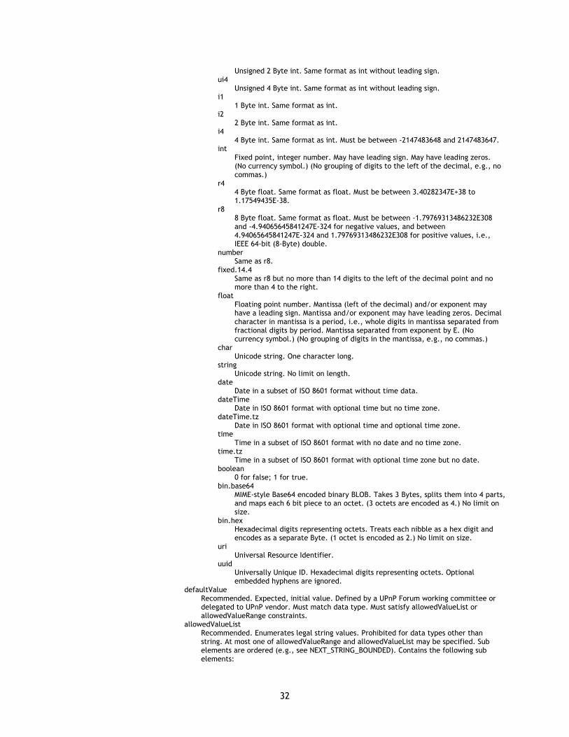
32
Unsigned 2 Byte int. Same format as int without leading sign. ui4
Unsigned 4 Byte int. Same format as int without leading sign. i1
1 Byte int. Same format as int. i2
2 Byte int. Same format as int. i4
4 Byte int. Same format as int. Must be between -2147483648 and 2147483647. int
Fixed point, integer number. May have leading sign. May have leading zeros. (No currency symbol.) (No grouping of digits to the left of the decimal, e.g., no commas.)
r4 4 Byte float. Same format as float. Must be between 3.40282347E+38 to 1.17549435E-38.
r8 8 Byte float. Same format as float. Must be between -1.79769313486232E308 and -4.94065645841247E-324 for negative values, and between 4.94065645841247E-324 and 1.79769313486232E308 for positive values, i.e., IEEE 64-bit (8-Byte) double.
number Same as r8.
fixed.14.4 Same as r8 but no more than 14 digits to the left of the decimal point and no more than 4 to the right.
float Floating point number. Mantissa (left of the decimal) and/or exponent may have a leading sign. Mantissa and/or exponent may have leading zeros. Decimal character in mantissa is a period, i.e., whole digits in mantissa separated from fractional digits by period. Mantissa separated from exponent by E. (No currency symbol.) (No grouping of digits in the mantissa, e.g., no commas.)
char Unicode string. One character long.
string Unicode string. No limit on length.
date Date in a subset of ISO 8601 format without time data.
dateTime Date in ISO 8601 format with optional time but no time zone.
dateTime.tz Date in ISO 8601 format with optional time and optional time zone.
time Time in a subset of ISO 8601 format with no date and no time zone.
time.tz Time in a subset of ISO 8601 format with optional time zone but no date.
boolean 0 for false; 1 for true.
bin.base64 MIME-style Base64 encoded binary BLOB. Takes 3 Bytes, splits them into 4 parts, and maps each 6 bit piece to an octet. (3 octets are encoded as 4.) No limit on size.
bin.hex Hexadecimal digits representing octets. Treats each nibble as a hex digit and encodes as a separate Byte. (1 octet is encoded as 2.) No limit on size.
uri Universal Resource Identifier.
uuid Universally Unique ID. Hexadecimal digits representing octets. Optional embedded hyphens are ignored.
defaultValue Recommended. Expected, initial value. Defined by a UPnP Forum working committee or delegated to UPnP vendor. Must match data type. Must satisfy allowedValueList or allowedValueRange constraints.
allowedValueList Recommended. Enumerates legal string values. Prohibited for data types other than string. At most one of allowedValueRange and allowedValueList may be specified. Sub elements are ordered (e.g., see NEXT_STRING_BOUNDED). Contains the following sub elements:
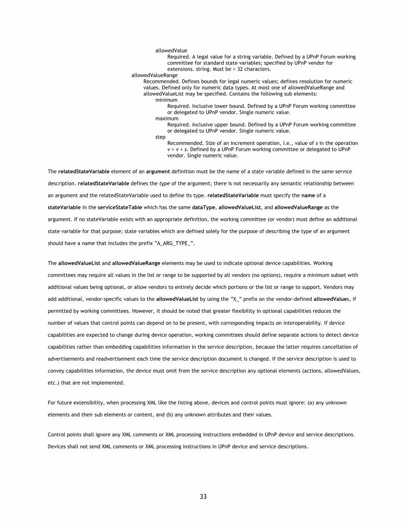
33
allowedValue Required. A legal value for a string variable. Defined by a UPnP Forum working committee for standard state variables; specified by UPnP vendor for extensions. string. Must be < 32 characters.
allowedValueRange Recommended. Defines bounds for legal numeric values; defines resolution for numeric values. Defined only for numeric data types. At most one of allowedValueRange and allowedValueList may be specified. Contains the following sub elements:
minimum Required. Inclusive lower bound. Defined by a UPnP Forum working committee or delegated to UPnP vendor. Single numeric value.
maximum Required. Inclusive upper bound. Defined by a UPnP Forum working committee or delegated to UPnP vendor. Single numeric value.
step Recommended. Size of an increment operation, i.e., value of s in the operation v = v + s. Defined by a UPnP Forum working committee or delegated to UPnP vendor. Single numeric value.
The relatedStateVariable element of an argument definition must be the name of a state variable defined in the same service
description. relatedStateVariable defines the type of the argument; there is not necessarily any semantic relationship between
an argument and the relatedStateVariable used to define its type. relatedStateVariable must specify the name of a
stateVariable in the serviceStateTable which has the same dataType, allowedValueList, and allowedValueRange as the
argument. If no stateVariable exists with an appropriate definition, the working committee (or vendor) must define an additional
state variable for that purpose; state variables which are defined solely for the purpose of describing the type of an argument
should have a name that includes the prefix “A_ARG_TYPE_”.
The allowedValueList and allowedValueRange elements may be used to indicate optional device capabilities. Working
committees may require all values in the list or range to be supported by all vendors (no options), require a minimum subset with
additional values being optional, or allow vendors to entirely decide which portions or the list or range to support. Vendors may
add additional, vendor-specific values to the allowedValueList by using the “X_” prefix on the vendor-defined allowedValues, if
permitted by working committees. However, it should be noted that greater flexibility in optional capabilities reduces the
number of values that control points can depend on to be present, with corresponding impacts on interoperability. If device
capabilities are expected to change during device operation, working committees should define separate actions to detect device
capabilities rather than embedding capabilities information in the service description, because the latter requires cancellation of
advertisements and readvertisement each time the service description document is changed. If the service description is used to
convey capabilities information, the device must omit from the service description any optional elements (actions, allowedValues,
etc.) that are not implemented.
For future extensibility, when processing XML like the listing above, devices and control points must ignore: (a) any unknown
elements and their sub elements or content, and (b) any unknown attributes and their values.
Control points shall ignore any XML comments or XML processing instructions embedded in UPnP device and service descriptions.
Devices shall not send XML comments or XML processing instructions in UPnP device and service descriptions.
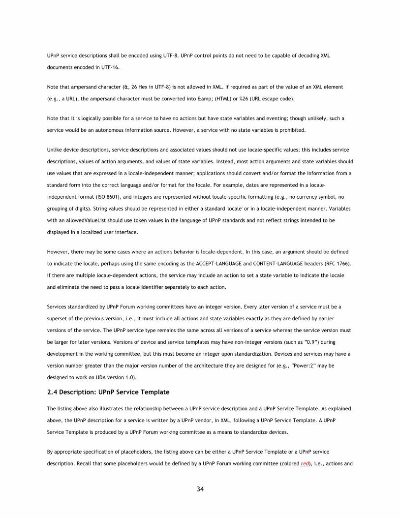
34
UPnP service descriptions shall be encoded using UTF-8. UPnP control points do not need to be capable of decoding XML
documents encoded in UTF-16.
Note that ampersand character (&, 26 Hex in UTF-8) is not allowed in XML. If required as part of the value of an XML element
(e.g., a URL), the ampersand character must be converted into & (HTML) or %26 (URL escape code).
Note that it is logically possible for a service to have no actions but have state variables and eventing; though unlikely, such a
service would be an autonomous information source. However, a service with no state variables is prohibited.
Unlike device descriptions, service descriptions and associated values should not use locale-specific values; this includes service
descriptions, values of action arguments, and values of state variables. Instead, most action arguments and state variables should
use values that are expressed in a locale-independent manner; applications should convert and/or format the information from a
standard form into the correct language and/or format for the locale. For example, dates are represented in a locale-
independent format (ISO 8601), and integers are represented without locale-specific formatting (e.g., no currency symbol, no
grouping of digits). String values should be represented in either a standard 'locale' or in a locale-independent manner. Variables
with an allowedValueList should use token values in the language of UPnP standards and not reflect strings intended to be
displayed in a localized user interface.
However, there may be some cases where an action's behavior is locale-dependent. In this case, an argument should be defined
to indicate the locale, perhaps using the same encoding as the ACCEPT-LANGUAGE and CONTENT-LANGUAGE headers (RFC 1766).
If there are multiple locale-dependent actions, the service may include an action to set a state variable to indicate the locale
and eliminate the need to pass a locale identifier separately to each action.
Services standardized by UPnP Forum working committees have an integer version. Every later version of a service must be a
superset of the previous version, i.e., it must include all actions and state variables exactly as they are defined by earlier
versions of the service. The UPnP service type remains the same across all versions of a service whereas the service version must
be larger for later versions. Versions of device and service templates may have non-integer versions (such as “0.9”) during
development in the working committee, but this must become an integer upon standardization. Devices and services may have a
version number greater than the major version number of the architecture they are designed for (e.g., “Power:2” may be
designed to work on UDA version 1.0).
2.4 Description: UPnP Service Template
The listing above also illustrates the relationship between a UPnP service description and a UPnP Service Template. As explained
above, the UPnP description for a service is written by a UPnP vendor, in XML, following a UPnP Service Template. A UPnP
Service Template is produced by a UPnP Forum working committee as a means to standardize devices.
By appropriate specification of placeholders, the listing above can be either a UPnP Service Template or a UPnP service
description. Recall that some placeholders would be defined by a UPnP Forum working committee (colored red), i.e., actions and

35
their parameters, and states and their data type, range, and event characteristics. If these were specified, the listing above
would be a UPnP Service Template, codifying the standard for this type of service. Along with UPnP Device Templates (cf.
section on Description), UPnP Service Templates are one of the key deliverables from UPnP Forum working committees.
Taking this another step further, the remaining placeholders in the listing above would be specified by a UPnP vendor (colored
purple), i.e., additional, vendor-specified actions and state variables. If these placeholders were specified (as well as the others),
the listing would be a UPnP service description, suitable for effective control of the service within a device.
Put another way, the UPnP Service Template defines the overall type of service, and each UPnP service description instantiates
that template with vendor-specific additions. The first is created by a UPnP Forum working committee; the latter, by a UPnP
vendor.
2.5 Description: Non-standard vendor extensions
As explained above, UPnP vendors may differentiate their devices and extend a standard device by including additional services
and embedded devices. Similarly, UPnP vendors may extend a standard service by including additional actions or state variables.
Naming conventions for each of these are listed in the table below and explained in detail above.
Type of extension Standard Non-Standard
device type urn:schemas-upnp-org:device:deviceType:v urn:domain-name:device:deviceType:v
service type urn:schemas-upnp-org:service:serviceType:v urn:domain-name:service:serviceType:v
service ID urn:upnp-org:serviceId:serviceID urn:domain-name:serviceId:serviceID
action name Does not begin with X_ or A_. Begins with X_.
state variable name Does not begin with X_ or A_ (except A_ARG_TYPE). Begins with X_.
XML elements in device or service description
Defined by the UPnP Template Language.
Arbitrary XML scoped by an XML namespace and nested within an element that begins with X_.
XML attributes in device or service description
Defined by the UPnP Template Language.
Arbitrary attributes scoped by an XML namespace and begin with X_.
As the last two rows of the table above indicate, UPnP vendors may also add non-standard XML to a device or service description.
Each addition must be scoped by a vendor-supplied XML namespace. Arbitrary XML must be enclosed in an element that begins
with X_, and this element must be a sub element of a standard element that contains sub elements. Non-standard attributes may
be added to standard elements provided these attributes are scoped by an XML namespace and begin with X_.
To illustrate this, below are listings with placeholders (in italics) for actual elements and values. Some of these placeholders
would be specified by a UPnP vendor (purple) and some are defined by the UPnP Device Architecture (green).
<RootStandardElement xmlns="urn:schemas-upnp-org:device-1-0" xmlns:n="domain-name:schema-name"> other XML <AnyStandardElement n:X_VendorAttribute="arbitrary string value"> other XML </AnyStandardElement>

36
other XML </RootStandardElement>
RootStandardElement
Required. A standard root element. xmlns attribute defines namespaces, in this case, a standard UPnP namespace and a non-standard namespace with the prefix n.
• For device descriptions, must be root.
• For service descriptions, must be scpd.
AnyStandardElement Required. Any standard element, root or otherwise, content of text or element only. Must already be included as part of the standard device or service description. X_VendorAttribute must begin with X_. (Prefix A_ is reserved.) May have an arbitrary string value.
<EltOnlyStandardElement n:X_VendorAttribute="vendor value"> <n:X_VendorElement xmlns:n="domain-name:schema-name"> arbitrary XML </n:X_VendorElement> </EltOnlyStandardElement>
EltOnlyStandardElement
Required. Element with content of element only. Must already be included as part of the standard device or service description.
• For device descriptions, must be one of: root, specVersion, device, iconList, icon, serviceList, service,
and/or deviceList.
• For service descriptions, must be one of: scpd, actionList, action, argumentList, argument,
serviceStateTable, stateVariable, allowedValueList, and/or allowedValueRange.
X_VendorElement Required. Must begin with X_. (Prefix A_ is reserved.) Must have a value for the xmlns attribute. May contain arbitrary XML.
Control points that do not understand these XML additions must ignore them.
2.6 Description: UPnP Template Language for devices
The paragraphs above explain UPnP device descriptions and illustrate how one would be instantiated from a UPnP Device
Template. As explained, UPnP Device Templates are produced by UPnP Forum working committees, and these templates are
derived from the UPnP Template Language. This template language defines valid templates for devices and services. Below is a
listing and explanation of this language as it pertains to devices.
The UPnP Template Language is written in XML syntax and is derived from XML Schema (Part 1: Structures, Part 2: Datatypes).
XML Schema provides a set of XML constructions that express language concepts like required vs. optional elements, element
nesting, and data types for values (as well as other properties not of interest here). The UPnP Template Language uses these XML
Schema constructions to define elements like specVersion, URLBase, deviceType, et al listed in detail above. Because the UPnP
Template Language is constructed using another, precise language, it is unambiguous. And because the UPnP Template Language,
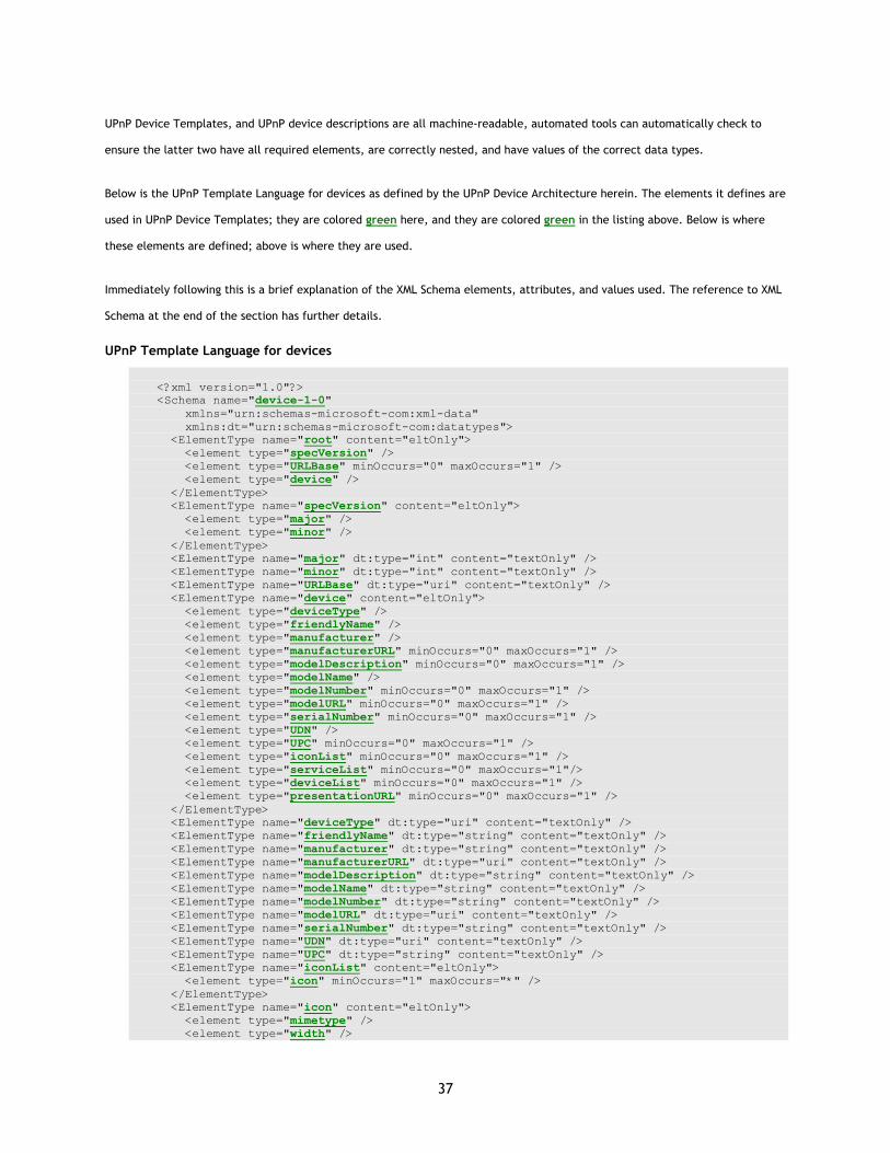
37
UPnP Device Templates, and UPnP device descriptions are all machine-readable, automated tools can automatically check to
ensure the latter two have all required elements, are correctly nested, and have values of the correct data types.
Below is the UPnP Template Language for devices as defined by the UPnP Device Architecture herein. The elements it defines are
used in UPnP Device Templates; they are colored green here, and they are colored green in the listing above. Below is where
these elements are defined; above is where they are used.
Immediately following this is a brief explanation of the XML Schema elements, attributes, and values used. The reference to XML
Schema at the end of the section has further details.
UPnP Template Language for devices
<?xml version="1.0"?> <Schema name="device-1-0" xmlns="urn:schemas-microsoft-com:xml-data" xmlns:dt="urn:schemas-microsoft-com:datatypes"> <ElementType name="root" content="eltOnly"> <element type="specVersion" /> <element type="URLBase" minOccurs="0" maxOccurs="1" /> <element type="device" /> </ElementType> <ElementType name="specVersion" content="eltOnly"> <element type="major" /> <element type="minor" /> </ElementType> <ElementType name="major" dt:type="int" content="textOnly" /> <ElementType name="minor" dt:type="int" content="textOnly" /> <ElementType name="URLBase" dt:type="uri" content="textOnly" /> <ElementType name="device" content="eltOnly"> <element type="deviceType" /> <element type="friendlyName" /> <element type="manufacturer" /> <element type="manufacturerURL" minOccurs="0" maxOccurs="1" /> <element type="modelDescription" minOccurs="0" maxOccurs="1" /> <element type="modelName" /> <element type="modelNumber" minOccurs="0" maxOccurs="1" /> <element type="modelURL" minOccurs="0" maxOccurs="1" /> <element type="serialNumber" minOccurs="0" maxOccurs="1" /> <element type="UDN" /> <element type="UPC" minOccurs="0" maxOccurs="1" /> <element type="iconList" minOccurs="0" maxOccurs="1" /> <element type="serviceList" minOccurs="0" maxOccurs="1"/> <element type="deviceList" minOccurs="0" maxOccurs="1" /> <element type="presentationURL" minOccurs="0" maxOccurs="1" /> </ElementType> <ElementType name="deviceType" dt:type="uri" content="textOnly" /> <ElementType name="friendlyName" dt:type="string" content="textOnly" /> <ElementType name="manufacturer" dt:type="string" content="textOnly" /> <ElementType name="manufacturerURL" dt:type="uri" content="textOnly" /> <ElementType name="modelDescription" dt:type="string" content="textOnly" /> <ElementType name="modelName" dt:type="string" content="textOnly" /> <ElementType name="modelNumber" dt:type="string" content="textOnly" /> <ElementType name="modelURL" dt:type="uri" content="textOnly" /> <ElementType name="serialNumber" dt:type="string" content="textOnly" /> <ElementType name="UDN" dt:type="uri" content="textOnly" /> <ElementType name="UPC" dt:type="string" content="textOnly" /> <ElementType name="iconList" content="eltOnly"> <element type="icon" minOccurs="1" maxOccurs="*" /> </ElementType> <ElementType name="icon" content="eltOnly"> <element type="mimetype" /> <element type="width" />

38
<element type="height" /> <element type="depth" /> <element type="url" /> </ElementType> <ElementType name="mimetype" dt:type="string" content="textOnly" /> <ElementType name="width" dt:type="int" content="textOnly" /> <ElementType name="height" dt:type="int" content="textOnly" /> <ElementType name="depth" dt:type="int" content="textOnly" /> <ElementType name="url" dt:type="uri" content="textOnly" /> <ElementType name="serviceList" content="eltOnly"> <element type="service" minOccurs="0" maxOccurs="*" /> </ElementType> <ElementType name="service" content="eltOnly"> <element type="serviceType" /> <element type="serviceId" /> <element type="SCPDURL" /> <element type="controlURL" /> <element type="eventSubURL" /> </ElementType> <ElementType name="serviceType" dt:type="uri" content="textOnly" /> <ElementType name="serviceId" dt:type="uri" content="textOnly" /> <ElementType name="SCPDURL" dt:type="uri" content="textOnly" /> <ElementType name="controlURL" dt:type="uri" content="textOnly" /> <ElementType name="eventSubURL" dt:type="uri" content="textOnly" /> <ElementType name="deviceList" content="eltOnly"> <element type="device" minOccurs="1" maxOccurs="*" /> </ElementType> <ElementType name="presentationURL" dt:type="uri" content="textOnly" /> </Schema>
ElementType
Defines an element in the new, derived language. name attribute defines element name. dt:type attribute defines the data type for the value of element in the new, derived language.
element References an element for the purposes of declaring nesting. minOccurs attribute defines minimum number of times the element must occur; default is minOccurs = 1; optional elements have minOccurs = 0. maxOccurs attribute defines maximum number of times the element must occur; default is maxOccurs = 1; elements that can appear one or more times have maxOccurs = *. Content= “textOnly” means the element does not contain subelements; content=“eltOnly” means the element contains subelements.
2.7 Description: UPnP Template Language for services
The paragraphs above explain UPnP service descriptions and illustrate how one would be instantiated from a UPnP Service
Template. Like UPnP Device Templates, UPnP Service Templates are produced by UPnP Forum working committees, and these
templates are derived from the UPnP Template Language. This template language defines valid templates for devices and
services. As explained above, the UPnP Template Language is written in XML syntax and is derived from XML Schema (Part 1:
Structures, Part 2: Datatypes). Below is a listing of this language as it pertains to services. The elements it defines are used in
UPnP Service Templates; they are colored green here, and they are colored green in the listing above. Below is where these
elements are defined; above is where they are used.
Immediately following this is a brief explanation of the XML Schema elements, attributes, and values used. The reference to XML
Schema at the end of the section has further details.
UPnP Template Language for services
<?xml version="1.0"?> <Schema name="service-1-0" xmlns="urn:schemas-microsoft-com:xml-data" xmlns:dt="urn:schemas-microsoft-com:datatypes">

39
<ElementType name="scpd" content="eltOnly"> <element type="specVersion" /> <element type="actionList" minOccurs="0" maxOccurs="1" /> <element type="serviceStateTable" /> </ElementType> <ElementType name="specVersion" content="eltOnly"> <element type="major" /> <element type="minor" /> </ElementType> <ElementType name="major" dt:type="int" content="textOnly" /> <ElementType name="minor" dt:type="int" content="textOnly" /> <ElementType name="actionList" content="eltOnly"> <element type="action" minOccurs="1" maxOccurs="*" /> </ElementType> <ElementType name="action" content="eltOnly"> <element type="name" /> <element type="argumentList" minOccurs="0" maxOccurs="1" /> </ElementType> <ElementType name="name" dt:type="string" content="textOnly" /> <ElementType name="argumentList" content="eltOnly"> <element type="argument" minOccurs="1" maxOccurs="*" /> </ElementType> <ElementType name="argument" content="eltOnly"> <element type="name" /> <element type="direction" /> <element type="retval" minOccurs="0" maxOccurs="1" /> <element type="relatedStateVariable" /> </ElementType> <ElementType name="direction" dt:type="string" content="textOnly" /> <ElementType name="retval" content="empty" /> <ElementType name="relatedStateVariable" dt:type="string" content="textOnly" /> <ElementType name="serviceStateTable" content="eltOnly"> <element type="stateVariable" minOccurs="1" maxOccurs="*" /> </ElementType> <ElementType name="stateVariable" content="eltOnly"> <element type="name" /> <element type="dataType" /> <element type="defaultValue" minOccurs="0" maxOccurs="1" /> <group minOccurs="0" maxOccurs="1" order="one"> <element type="allowedValueList" /> <element type="allowedValueRange" /> </group> <AttributeType name="sendEvents" /> <attribute default="yes" type="sendEvents" required="no" /> </ElementType> <ElementType name="dataType" dt:type="string" content="textOnly" /> <ElementType name="defaultValue" dt:type="string" content="textOnly" /> <ElementType name="allowedValueList" content="eltOnly"> <element type="allowedValue" minOccurs="1" maxOccurs="*" /> </ElementType> <ElementType name="allowedValue" content="textOnly" /> <ElementType name="allowedValueRange" content="eltOnly"> <element type="minimum" /> <element type="maximum" /> <element type="step" minOccurs="0" maxOccurs="1" /> </ElementType> <ElementType name="minimum" dt:type="number" content="textOnly" /> <ElementType name="maximum" dt:type="number" content="textOnly" /> <ElementType name="step" dt:type="number" content="textOnly" /> </Schema>
attribute
References an attribute in the new, derived language for the purposes of declaring in which elements it may appear. Like any XML element, the AttributeType element may have attributes of its own. Using the required attribute within this element indicates whether the attribute must be present; optional attributes have required = no.
AttributeType Defines an attribute in the new, derived language. Like any XML element, the AttributeType element may have attributes of its own. Using the name attribute within this element defines the name of the attribute as it will be used in the derived language.
element
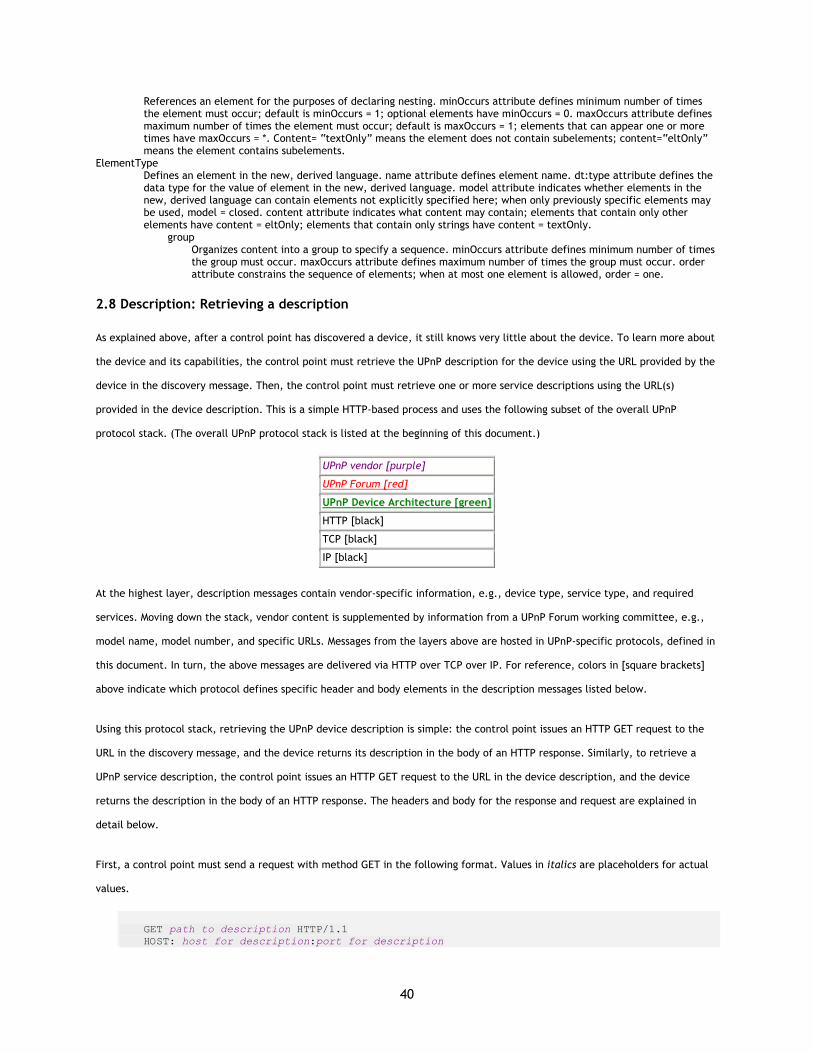
40
References an element for the purposes of declaring nesting. minOccurs attribute defines minimum number of times the element must occur; default is minOccurs = 1; optional elements have minOccurs = 0. maxOccurs attribute defines maximum number of times the element must occur; default is maxOccurs = 1; elements that can appear one or more times have maxOccurs = *. Content= “textOnly” means the element does not contain subelements; content=“eltOnly” means the element contains subelements.
ElementType Defines an element in the new, derived language. name attribute defines element name. dt:type attribute defines the data type for the value of element in the new, derived language. model attribute indicates whether elements in the new, derived language can contain elements not explicitly specified here; when only previously specific elements may be used, model = closed. content attribute indicates what content may contain; elements that contain only other elements have content = eltOnly; elements that contain only strings have content = textOnly.
group Organizes content into a group to specify a sequence. minOccurs attribute defines minimum number of times the group must occur. maxOccurs attribute defines maximum number of times the group must occur. order attribute constrains the sequence of elements; when at most one element is allowed, order = one.
2.8 Description: Retrieving a description
As explained above, after a control point has discovered a device, it still knows very little about the device. To learn more about
the device and its capabilities, the control point must retrieve the UPnP description for the device using the URL provided by the
device in the discovery message. Then, the control point must retrieve one or more service descriptions using the URL(s)
provided in the device description. This is a simple HTTP-based process and uses the following subset of the overall UPnP
protocol stack. (The overall UPnP protocol stack is listed at the beginning of this document.)
UPnP vendor [purple]
UPnP Forum [red]
UPnP Device Architecture [green]
HTTP [black]
TCP [black]
IP [black]
At the highest layer, description messages contain vendor-specific information, e.g., device type, service type, and required
services. Moving down the stack, vendor content is supplemented by information from a UPnP Forum working committee, e.g.,
model name, model number, and specific URLs. Messages from the layers above are hosted in UPnP-specific protocols, defined in
this document. In turn, the above messages are delivered via HTTP over TCP over IP. For reference, colors in [square brackets]
above indicate which protocol defines specific header and body elements in the description messages listed below.
Using this protocol stack, retrieving the UPnP device description is simple: the control point issues an HTTP GET request to the
URL in the discovery message, and the device returns its description in the body of an HTTP response. Similarly, to retrieve a
UPnP service description, the control point issues an HTTP GET request to the URL in the device description, and the device
returns the description in the body of an HTTP response. The headers and body for the response and request are explained in
detail below.
First, a control point must send a request with method GET in the following format. Values in italics are placeholders for actual
values.
GET path to description HTTP/1.1 HOST: host for description:port for description

41
ACCEPT-LANGUAGE: language preferred by control point
(No body for request to retrieve a description, but note that the message must have a blank line following the last HTTP header.)
Listed below are details for the request line and headers appearing in the listing above. All header values are case sensitive
except where noted.
Request line
GET Method defined by HTTP.
path to description Path component of device description URL (LOCATION header in discovery message) or of service description URL (SCPDURL element in device description). Single, relative URL.
HTTP/1.1 HTTP version.
Headers
HOST Required. Domain name or IP address and optional port components of device description URL (LOCATION header in discovery message) or of service description URL (SCPDURL element of device description). If the port is empty or not given, port 80 is assumed.
ACCEPT-LANGUAGE Recommended for retrieving device descriptions. Preferred language(s) for description. If no description is available in this language, device may return a description in a default language. RFC 1766 language tag(s).
After a control point sends a request, the device takes the second step and responds with a copy of its description. Including
expected transmission time, a device must respond within 30 seconds. If it fails to respond within this time, the control point
should re-send the request. A device must send a response in the following format. Values in italics are placeholders for actual
values.
HTTP/1.1 200 OK CONTENT-LANGUAGE: language used in description CONTENT-LENGTH: Bytes in body CONTENT-TYPE: text/xml DATE: when responded
The body of this response is a UPnP device or service description as explained in detail above.
A multi-homed device (one that supports multiple network interfaces or multiple IP addresses) must respond to a request using
the same interface and the same address on which the request was received.
Listed below are details for the headers appearing in the listing above. All header values are case sensitive except where noted.
Headers
CONTENT-LANGUAGE Required if and only if request included an ACCEPT-LANGUAGE header. Language of description. RFC 1766 language tag(s).
CONTENT-LENGTH Required. Length of body in Bytes. Integer.
CONTENT-TYPE Required. Must be text/xml.
DATE

42
Recommended. When response was generated. RFC 1123 date. SERVER
(No SERVER header is required for description messages.)
2.9 Description references
ISO 8601 ISO (International Organization for Standardization). Representations of dates and times, 1988-06-15. <http://www.w3.org/TR/1998/NOTE-datetime-19980827>
RFC 822 Standard for the format of ARPA Internet text messages. <http://www.ietf.org/rfc/rfc822.txt>.
RFC 1123 Includes format for dates, for, e.g., HTTP DATE header. <http://www.ietf.org/rfc/rfc1123.txt>
RFC 1766 Format for language tag for, e.g., HTTP ACCEPT-LANGUAGE header. <http://www.ietf.org/rfc/rfc1766.txt>. See also <http://www.loc.gov/standards/iso639-2> for language codes.
RFC 2045 Multipurpose Internet Mail Extensions (MIME) Part One: Format of Internet Message Bodies. <http://www.ietf.org/rfc/rfc2045.txt>.
RFC 2046 Multipurpose Internet Mail Extensions (MIME) Part Two: Media Types. <http://www.ietf.org/rfc/rfc2046.txt>.
RFC 2083 PNG (Portable Network Graphics) Specification Version 1.0. <http://www.ietf.org/rfc/rfc2083.txt>. See also <http://www.w3.org/TR/REC-png.html>
RFC 2387 Format for representing content type, e.g., mimetype element for an icon. <http://www.ietf.org/rfc/rfc2387.txt>
RFC 2396 Uniform Resource Indicators: Generic Syntax. Section 5, Relative URI References. <http://www.ietf.org/rfc/rfc2396.txt>.
UPC Universal Product Code. 12-digit, all-numeric code that identifies the consumer package. Managed by the Uniform Code Council. <http://www.uc-council.org/main/ID_Numbers_and_Bar_Codes.html>.
XML Extensible Markup Language. <http://www.w3.org/XML>.
XML Schema (Part 1: Structures, Part 2: Datatypes) Grammar defining UPnP Template Language. <http://www.w3.org/TR/xmlschema-1>, <http://www.w3.org/TR/xmlschema-2>.
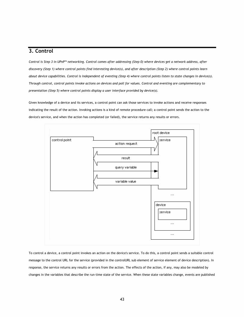
43
3. Control
Control is Step 3 in UPnP™ networking. Control comes after addressing (Step 0) where devices get a network address, after
discovery (Step 1) where control points find interesting device(s), and after description (Step 2) where control points learn
about device capabilities. Control is independent of eventing (Step 4) where control points listen to state changes in device(s).
Through control, control points invoke actions on devices and poll for values. Control and eventing are complementary to
presentation (Step 5) where control points display a user interface provided by device(s).
Given knowledge of a device and its services, a control point can ask those services to invoke actions and receive responses
indicating the result of the action. Invoking actions is a kind of remote procedure call; a control point sends the action to the
device's service, and when the action has completed (or failed), the service returns any results or errors.
To control a device, a control point invokes an action on the device's service. To do this, a control point sends a suitable control
message to the control URL for the service (provided in the controlURL sub element of service element of device description). In
response, the service returns any results or errors from the action. The effects of the action, if any, may also be modeled by
changes in the variables that describe the run-time state of the service. When these state variables change, events are published
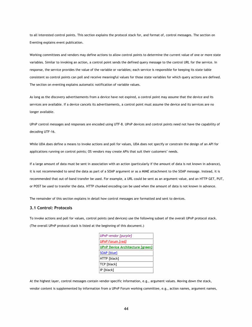
44
to all interested control points. This section explains the protocol stack for, and format of, control messages. The section on
Eventing explains event publication.
Working committees and vendors may define actions to allow control points to determine the current value of one or more state
variables. Similar to invoking an action, a control point sends the defined query message to the control URL for the service. In
response, the service provides the value of the variable or variables; each service is responsible for keeping its state table
consistent so control points can poll and receive meaningful values for those state variables for which query actions are defined.
The section on eventing explains automatic notification of variable values.
As long as the discovery advertisements from a device have not expired, a control point may assume that the device and its
services are available. If a device cancels its advertisements, a control point must assume the device and its services are no
longer available.
UPnP control messages and responses are encoded using UTF-8. UPnP devices and control points need not have the capability of
decoding UTF-16.
While UDA does define a means to invoke actions and poll for values, UDA does not specify or constrain the design of an API for
applications running on control points; OS vendors may create APIs that suit their customers’ needs.
If a large amount of data must be sent in association with an action (particularly if the amount of data is not known in advance),
it is not recommended to send the data as part of a SOAP argument or as a MIME attachment to the SOAP message. Instead, it is
recommended that out-of-band transfer be used. For example, a URL could be sent as an argument value, and an HTTP GET, PUT,
or POST be used to transfer the data. HTTP chunked encoding can be used when the amount of data is not known in advance.
The remainder of this section explains in detail how control messages are formatted and sent to devices.
3.1 Control: Protocols
To invoke actions and poll for values, control points (and devices) use the following subset of the overall UPnP protocol stack.
(The overall UPnP protocol stack is listed at the beginning of this document.)
UPnP vendor [purple]
UPnP Forum [red]
UPnP Device Architecture [green]
SOAP [blue]
HTTP [black]
TCP [black]
IP [black]
At the highest layer, control messages contain vendor-specific information, e.g., argument values. Moving down the stack,
vendor content is supplemented by information from a UPnP Forum working committee, e.g., action names, argument names,
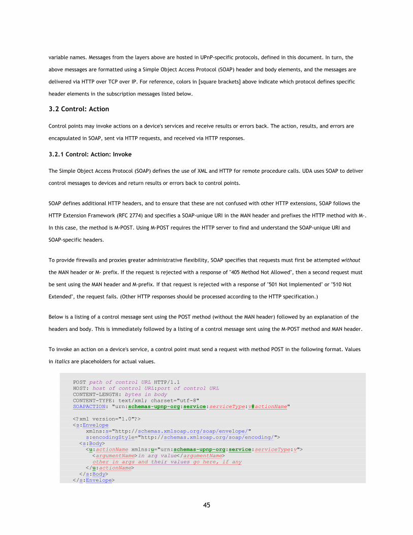
45
variable names. Messages from the layers above are hosted in UPnP-specific protocols, defined in this document. In turn, the
above messages are formatted using a Simple Object Access Protocol (SOAP) header and body elements, and the messages are
delivered via HTTP over TCP over IP. For reference, colors in [square brackets] above indicate which protocol defines specific
header elements in the subscription messages listed below.
3.2 Control: Action
Control points may invoke actions on a device's services and receive results or errors back. The action, results, and errors are
encapsulated in SOAP, sent via HTTP requests, and received via HTTP responses.
3.2.1 Control: Action: Invoke
The Simple Object Access Protocol (SOAP) defines the use of XML and HTTP for remote procedure calls. UDA uses SOAP to deliver
control messages to devices and return results or errors back to control points.
SOAP defines additional HTTP headers, and to ensure that these are not confused with other HTTP extensions, SOAP follows the
HTTP Extension Framework (RFC 2774) and specifies a SOAP-unique URI in the MAN header and prefixes the HTTP method with M-.
In this case, the method is M-POST. Using M-POST requires the HTTP server to find and understand the SOAP-unique URI and
SOAP-specific headers.
To provide firewalls and proxies greater administrative flexibility, SOAP specifies that requests must first be attempted without
the MAN header or M- prefix. If the request is rejected with a response of "405 Method Not Allowed", then a second request must
be sent using the MAN header and M-prefix. If that request is rejected with a response of "501 Not Implemented" or "510 Not
Extended", the request fails. (Other HTTP responses should be processed according to the HTTP specification.)
Below is a listing of a control message sent using the POST method (without the MAN header) followed by an explanation of the
headers and body. This is immediately followed by a listing of a control message sent using the M-POST method and MAN header.
To invoke an action on a device's service, a control point must send a request with method POST in the following format. Values
in italics are placeholders for actual values.
POST path of control URL HTTP/1.1 HOST: host of control URL:port of control URL CONTENT-LENGTH: bytes in body CONTENT-TYPE: text/xml; charset="utf-8" SOAPACTION: "urn:schemas-upnp-org:service:serviceType:v#actionName" <?xml version="1.0"?> <s:Envelope xmlns:s="http://schemas.xmlsoap.org/soap/envelope/" s:encodingStyle="http://schemas.xmlsoap.org/soap/encoding/"> <s:Body> <u:actionName xmlns:u="urn:schemas-upnp-org:service:serviceType:v"> <argumentName>in arg value</argumentName> other in args and their values go here, if any </u:actionName> </s:Body> </s:Envelope>

46
Listed below are details for the request line, headers, and body elements appearing in the listing above. All header values and
element names are case sensitive; values are not case sensitive except where noted. Except where noted, the order of elements
is insignificant. Except where noted, required elements must occur exactly once (no duplicates), and recommended or optional
elements may occur at most once.
Request line
POST Method defined by HTTP.
path control URL Path component of URL for control for this service (controlURL sub element of service element of device description). Single, relative URL.
HTTP/1.1 HTTP version.
Headers
HOST Required. Domain name or IP address and optional port components of URL for control for this service (controlURL sub element of service element of device description). If the port is empty or not given, port 80 is assumed.
ACCEPT-LANGUAGE (No ACCEPT-LANGUAGE header is used in control messages.)
CONTENT-LENGTH Required. Length of body in bytes. Integer.
CONTENT-TYPE Required. Must be text/xml. Should include character coding used, which must be “utf-8”.
MAN (No MAN header in request with method POST.)
SOAPACTION Required header defined by SOAP. Must be the service type, hash mark, and name of action to be invoked, all enclosed in double quotes. If used in a request with method M-POST, header name must be qualified with HTTP name space defined in MAN header. Single URI.
Body
Envelope Required element defined by SOAP. xmlns namespace attribute must be "http://schemas.xmlsoap.org/soap/envelope/". Must include encodingStyle attribute with value "http://schemas.xmlsoap.org/soap/encoding/". Contains the following sub elements: Body
Required element defined by SOAP. Should be qualified with SOAP namespace. Contains the following sub element:
actionName Required. Name of element is name of action to invoke. xmlns namespace attribute must be the service type enclosed in double quotes. Case sensitive. Must be the first sub element of Body. Contains the following, ordered sub element(s):
argumentName Required if and only if action has in arguments. Value to be passed to action. Repeat once for each in argument. (Element name not qualified by a namespace; element nesting context is sufficient.) Case sensitive. Single data type as defined by UPnP service description. Every “in” argument in the definition of the action in the service description must be included, in the same order as specified in the service description.
If the CONTENT-TYPE header specifies an unsupported value (other then “text/xml”) the device must return an HTTP status code
“415 Unsupported Media Type”.
For future extensibility, when processing XML like the listing above, devices and control points must ignore: (a) any unknown
elements and their sub elements or content, and (b) any unknown attributes and their values.
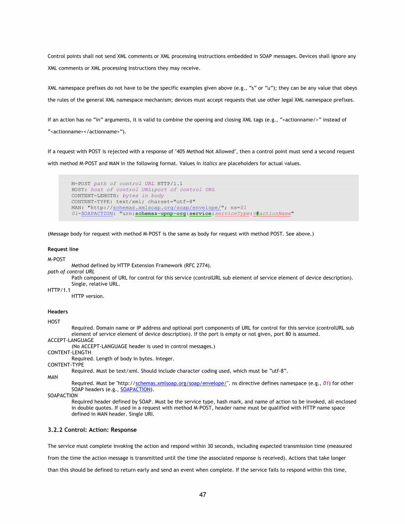
47
Control points shall not send XML comments or XML processing instructions embedded in SOAP messages. Devices shall ignore any
XML comments or XML processing instructions they may receive.
XML namespace prefixes do not have to be the specific examples given above (e.g., “s” or “u”); they can be any value that obeys
the rules of the general XML namespace mechanism; devices must accept requests that use other legal XML namespace prefixes.
If an action has no “in” arguments, it is valid to combine the opening and closing XML tags (e.g., “<actionname/>” instead of
“<actionname></actionname>”).
If a request with POST is rejected with a response of "405 Method Not Allowed", then a control point must send a second request
with method M-POST and MAN in the following format. Values in italics are placeholders for actual values.
M-POST path of control URL HTTP/1.1 HOST: host of control URL:port of control URL CONTENT-LENGTH: bytes in body CONTENT-TYPE: text/xml; charset="utf-8" MAN: "http://schemas.xmlsoap.org/soap/envelope/"; ns=01 01-SOAPACTION: "urn:schemas-upnp-org:service:serviceType:v#actionName"
(Message body for request with method M-POST is the same as body for request with method POST. See above.)
Request line
M-POST Method defined by HTTP Extension Framework (RFC 2774).
path of control URL Path component of URL for control for this service (controlURL sub element of service element of device description). Single, relative URL.
HTTP/1.1 HTTP version.
Headers
HOST Required. Domain name or IP address and optional port components of URL for control for this service (controlURL sub element of service element of device description). If the port is empty or not given, port 80 is assumed.
ACCEPT-LANGUAGE (No ACCEPT-LANGUAGE header is used in control messages.)
CONTENT-LENGTH Required. Length of body in bytes. Integer.
CONTENT-TYPE Required. Must be text/xml. Should include character coding used, which must be “utf-8”.
MAN Required. Must be "http://schemas.xmlsoap.org/soap/envelope/". ns directive defines namespace (e.g., 01) for other SOAP headers (e.g., SOAPACTION).
SOAPACTION Required header defined by SOAP. Must be the service type, hash mark, and name of action to be invoked, all enclosed in double quotes. If used in a request with method M-POST, header name must be qualified with HTTP name space defined in MAN header. Single URI.
3.2.2 Control: Action: Response
The service must complete invoking the action and respond within 30 seconds, including expected transmission time (measured
from the time the action message is transmitted until the time the associated response is received). Actions that take longer
than this should be defined to return early and send an event when complete. If the service fails to respond within this time,
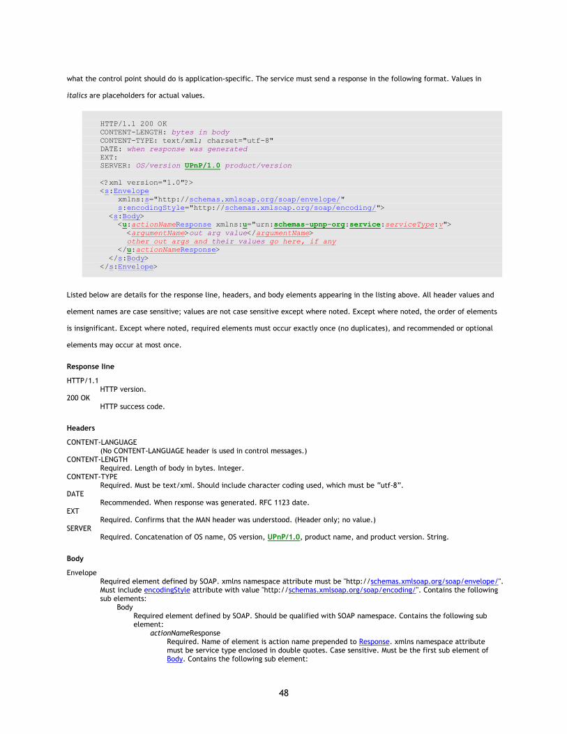
48
what the control point should do is application-specific. The service must send a response in the following format. Values in
italics are placeholders for actual values.
HTTP/1.1 200 OK CONTENT-LENGTH: bytes in body CONTENT-TYPE: text/xml; charset="utf-8" DATE: when response was generated EXT: SERVER: OS/version UPnP/1.0 product/version <?xml version="1.0"?> <s:Envelope xmlns:s="http://schemas.xmlsoap.org/soap/envelope/" s:encodingStyle="http://schemas.xmlsoap.org/soap/encoding/"> <s:Body> <u:actionNameResponse xmlns:u="urn:schemas-upnp-org:service:serviceType:v"> <argumentName>out arg value</argumentName> other out args and their values go here, if any </u:actionNameResponse> </s:Body> </s:Envelope>
Listed below are details for the response line, headers, and body elements appearing in the listing above. All header values and
element names are case sensitive; values are not case sensitive except where noted. Except where noted, the order of elements
is insignificant. Except where noted, required elements must occur exactly once (no duplicates), and recommended or optional
elements may occur at most once.
Response line
HTTP/1.1 HTTP version.
200 OK HTTP success code.
Headers
CONTENT-LANGUAGE (No CONTENT-LANGUAGE header is used in control messages.)
CONTENT-LENGTH Required. Length of body in bytes. Integer.
CONTENT-TYPE Required. Must be text/xml. Should include character coding used, which must be “utf-8”.
DATE Recommended. When response was generated. RFC 1123 date.
EXT Required. Confirms that the MAN header was understood. (Header only; no value.)
SERVER Required. Concatenation of OS name, OS version, UPnP/1.0, product name, and product version. String.
Body
Envelope Required element defined by SOAP. xmlns namespace attribute must be "http://schemas.xmlsoap.org/soap/envelope/". Must include encodingStyle attribute with value "http://schemas.xmlsoap.org/soap/encoding/". Contains the following sub elements:
Body Required element defined by SOAP. Should be qualified with SOAP namespace. Contains the following sub element:
actionNameResponse Required. Name of element is action name prepended to Response. xmlns namespace attribute must be service type enclosed in double quotes. Case sensitive. Must be the first sub element of Body. Contains the following sub element:
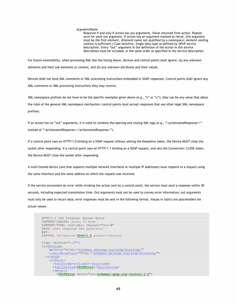
49
argumentName Required if and only if action has out arguments. Value returned from action. Repeat once for each out argument. If action has an argument marked as retval, this argument must be the first element. (Element name not qualified by a namespace; element nesting context is sufficient.) Case sensitive. Single data type as defined by UPnP service description. Every “out” argument in the definition of the action in the service description must be included, in the same order as specified in the service description.
For future extensibility, when processing XML like the listing above, devices and control points must ignore: (a) any unknown
elements and their sub elements or content, and (b) any unknown attributes and their values.
Devices shall not send XML comments or XML processing instructions embedded in SOAP responses. Control points shall ignore any
XML comments or XML processing instructions they may receive.
XML namespace prefixes do not have to be the specific examples given above (e.g., “s” or “u”); they can be any value that obeys
the rules of the general XML namespace mechanism; control points must accept responses that use other legal XML namespace
prefixes.
If an action has no “out” arguments, it is valid to combine the opening and closing XML tags (e.g., “<actionnameResponse/>”
instead of “<actionnameResponse></actionnameResponse>”).
If a control point uses an HTTP/1.0 binding on a SOAP request without setting the KeepAlive token, the Device MUST close the
socket after responding. If a control point uses an HTTP/1.1 binding on a SOAP request, and sets the Connection: CLOSE token,
the Device MUST close the socket after responding.
A multi-homed device (one that supports multiple network interfaces or multiple IP addresses) must respond to a request using
the same interface and the same address on which the request was received.
If the service encounters an error while invoking the action sent by a control point, the service must send a response within 30
seconds, including expected transmission time. Out arguments must not be used to convey error information; out arguments
must only be used to return data; error responses must be sent in the following format. Values in italics are placeholders for
actual values.
HTTP/1.1 500 Internal Server Error CONTENT-LENGTH: bytes in body CONTENT-TYPE: text/xml; charset="utf-8" DATE: when response was generated EXT: SERVER: OS/version UPnP/1.0 product/version <?xml version="1.0"?> <s:Envelope xmlns:s="http://schemas.xmlsoap.org/soap/envelope/" s:encodingStyle="http://schemas.xmlsoap.org/soap/encoding/"> <s:Body> <s:Fault> <faultcode>s:Client</faultcode> <faultstring>UPnPError</faultstring> <detail> <UPnPError xmlns="urn:schemas-upnp-org:control-1-0">
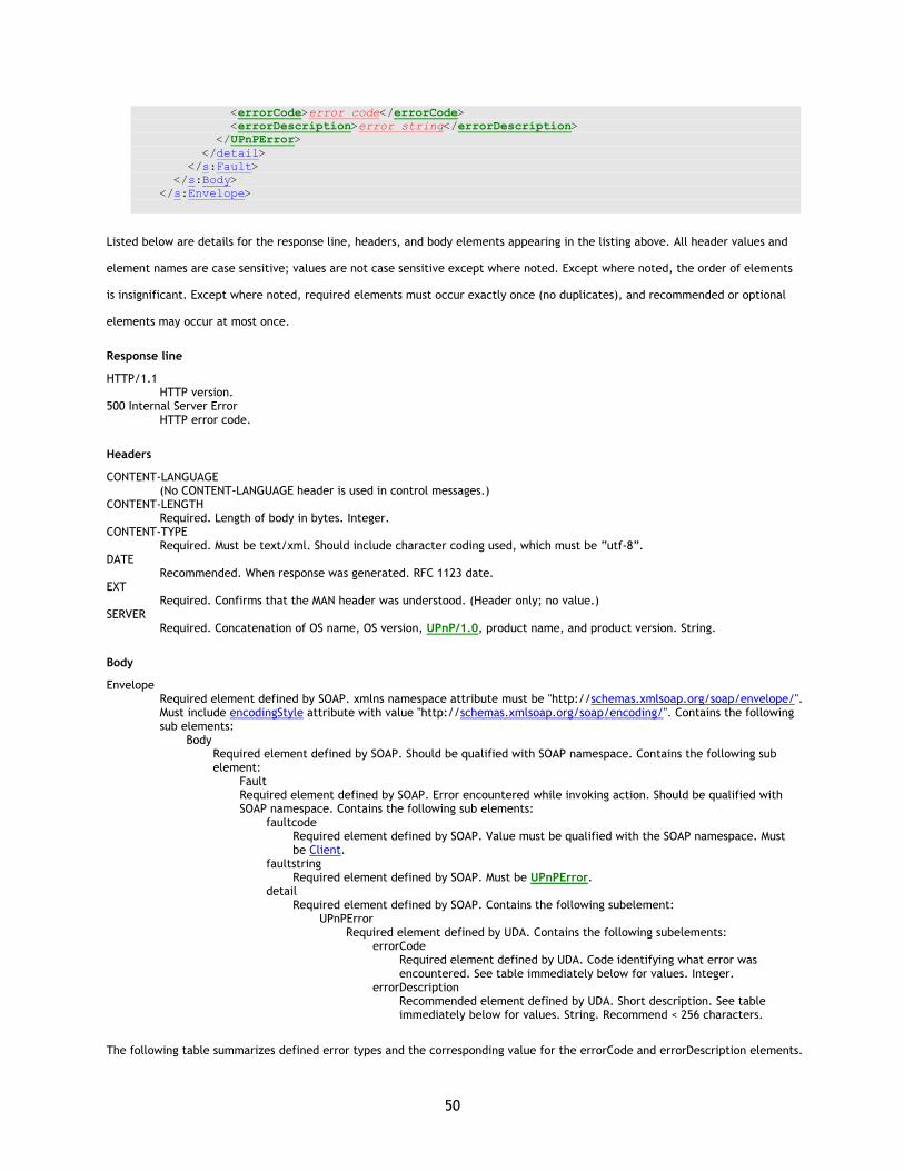
50
<errorCode>error code</errorCode> <errorDescription>error string</errorDescription> </UPnPError> </detail> </s:Fault> </s:Body> </s:Envelope>
Listed below are details for the response line, headers, and body elements appearing in the listing above. All header values and
element names are case sensitive; values are not case sensitive except where noted. Except where noted, the order of elements
is insignificant. Except where noted, required elements must occur exactly once (no duplicates), and recommended or optional
elements may occur at most once.
Response line
HTTP/1.1 HTTP version.
500 Internal Server Error HTTP error code.
Headers
CONTENT-LANGUAGE (No CONTENT-LANGUAGE header is used in control messages.)
CONTENT-LENGTH Required. Length of body in bytes. Integer.
CONTENT-TYPE Required. Must be text/xml. Should include character coding used, which must be “utf-8”.
DATE Recommended. When response was generated. RFC 1123 date.
EXT Required. Confirms that the MAN header was understood. (Header only; no value.)
SERVER Required. Concatenation of OS name, OS version, UPnP/1.0, product name, and product version. String.
Body
Envelope Required element defined by SOAP. xmlns namespace attribute must be "http://schemas.xmlsoap.org/soap/envelope/". Must include encodingStyle attribute with value "http://schemas.xmlsoap.org/soap/encoding/". Contains the following sub elements:
Body Required element defined by SOAP. Should be qualified with SOAP namespace. Contains the following sub element:
Fault Required element defined by SOAP. Error encountered while invoking action. Should be qualified with SOAP namespace. Contains the following sub elements:
faultcode Required element defined by SOAP. Value must be qualified with the SOAP namespace. Must be Client.
faultstring Required element defined by SOAP. Must be UPnPError.
detail Required element defined by SOAP. Contains the following subelement:
UPnPError Required element defined by UDA. Contains the following subelements:
errorCode Required element defined by UDA. Code identifying what error was encountered. See table immediately below for values. Integer.
errorDescription Recommended element defined by UDA. Short description. See table immediately below for values. String. Recommend < 256 characters.
The following table summarizes defined error types and the corresponding value for the errorCode and errorDescription elements.
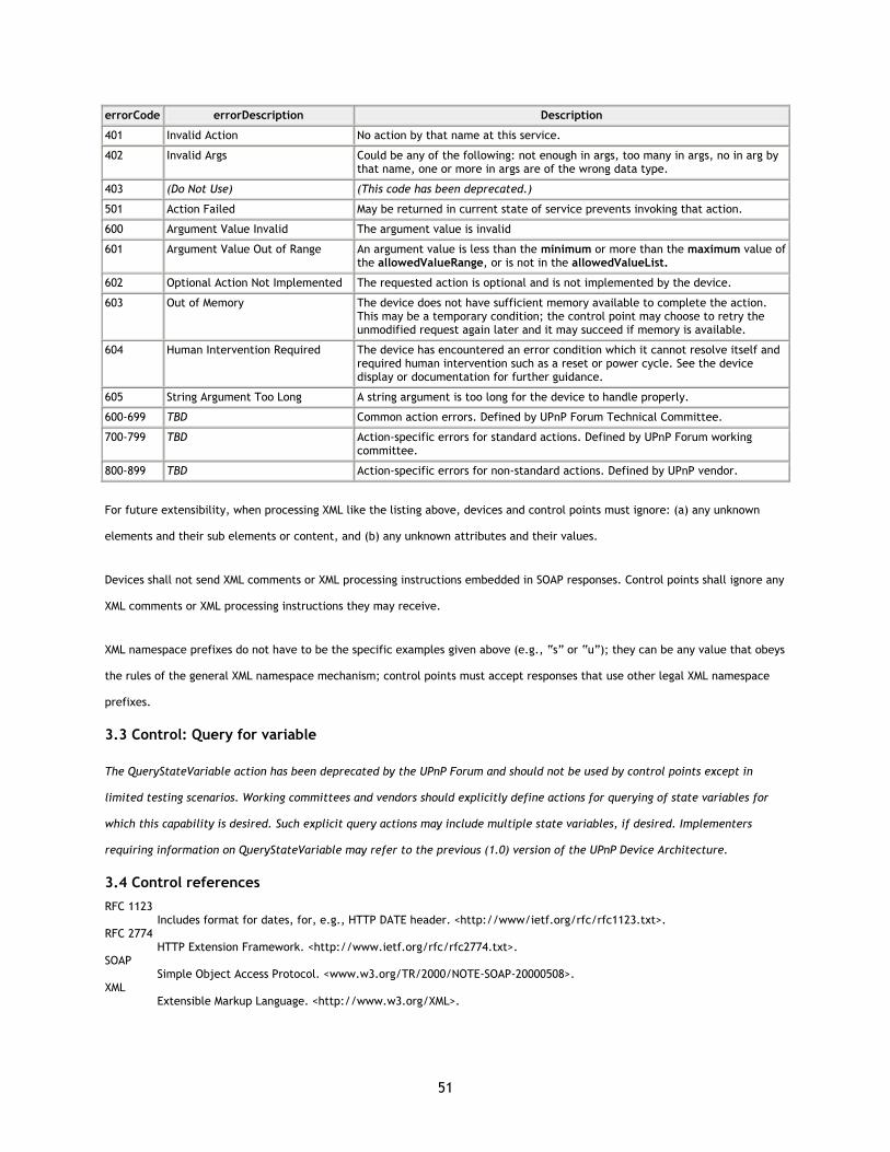
51
errorCode errorDescription Description
401 Invalid Action No action by that name at this service.
402 Invalid Args Could be any of the following: not enough in args, too many in args, no in arg by that name, one or more in args are of the wrong data type.
403 (Do Not Use) (This code has been deprecated.)
501 Action Failed May be returned in current state of service prevents invoking that action.
600 Argument Value Invalid The argument value is invalid
601 Argument Value Out of Range An argument value is less than the minimum or more than the maximum value of the allowedValueRange, or is not in the allowedValueList.
602 Optional Action Not Implemented The requested action is optional and is not implemented by the device.
603 Out of Memory The device does not have sufficient memory available to complete the action. This may be a temporary condition; the control point may choose to retry the unmodified request again later and it may succeed if memory is available.
604 Human Intervention Required The device has encountered an error condition which it cannot resolve itself and required human intervention such as a reset or power cycle. See the device display or documentation for further guidance.
605 String Argument Too Long A string argument is too long for the device to handle properly.
600-699 TBD Common action errors. Defined by UPnP Forum Technical Committee.
700-799 TBD Action-specific errors for standard actions. Defined by UPnP Forum working committee.
800-899 TBD Action-specific errors for non-standard actions. Defined by UPnP vendor.
For future extensibility, when processing XML like the listing above, devices and control points must ignore: (a) any unknown
elements and their sub elements or content, and (b) any unknown attributes and their values.
Devices shall not send XML comments or XML processing instructions embedded in SOAP responses. Control points shall ignore any
XML comments or XML processing instructions they may receive.
XML namespace prefixes do not have to be the specific examples given above (e.g., “s” or “u”); they can be any value that obeys
the rules of the general XML namespace mechanism; control points must accept responses that use other legal XML namespace
prefixes.
3.3 Control: Query for variable
The QueryStateVariable action has been deprecated by the UPnP Forum and should not be used by control points except in
limited testing scenarios. Working committees and vendors should explicitly define actions for querying of state variables for
which this capability is desired. Such explicit query actions may include multiple state variables, if desired. Implementers
requiring information on QueryStateVariable may refer to the previous (1.0) version of the UPnP Device Architecture.
3.4 Control references
RFC 1123 Includes format for dates, for, e.g., HTTP DATE header. <http://www/ietf.org/rfc/rfc1123.txt>.
RFC 2774 HTTP Extension Framework. <http://www.ietf.org/rfc/rfc2774.txt>.
SOAP Simple Object Access Protocol. <www.w3.org/TR/2000/NOTE-SOAP-20000508>.
XML Extensible Markup Language. <http://www.w3.org/XML>.
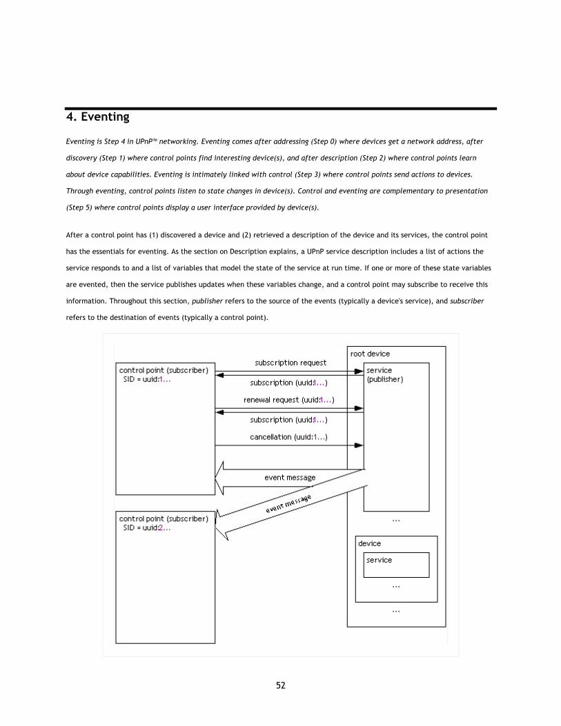
52
4. Eventing
Eventing is Step 4 in UPnP™ networking. Eventing comes after addressing (Step 0) where devices get a network address, after
discovery (Step 1) where control points find interesting device(s), and after description (Step 2) where control points learn
about device capabilities. Eventing is intimately linked with control (Step 3) where control points send actions to devices.
Through eventing, control points listen to state changes in device(s). Control and eventing are complementary to presentation
(Step 5) where control points display a user interface provided by device(s).
After a control point has (1) discovered a device and (2) retrieved a description of the device and its services, the control point
has the essentials for eventing. As the section on Description explains, a UPnP service description includes a list of actions the
service responds to and a list of variables that model the state of the service at run time. If one or more of these state variables
are evented, then the service publishes updates when these variables change, and a control point may subscribe to receive this
information. Throughout this section, publisher refers to the source of the events (typically a device's service), and subscriber
refers to the destination of events (typically a control point).

53
To subscribe to eventing, a subscriber sends a subscription message. If the subscription is accepted, the publisher responds with
a duration for the subscription. To keep the subscription active, a subscriber must renew its subscription before the subscription
expires. When a subscriber no longer needs eventing from a publisher, the subscriber should cancel its subscription. This section
explains subscription, renewal, and cancellation messages in detail below.
The publisher notes changes to state variables by sending event messages. Event messages contain the names of one of more
state variables and the current value of those variables, expressed in XML. A special initial event message is sent when a
subscriber first subscribes; this event message contains the names and values for all evented variables and allows the subscriber
to initialize its model of the state of the service. To support scenarios with multiple control points, eventing can be used to keep
interested control points informed about the effects of actions performed by other control points or using other mechanisms for
device control (such as front panel controls). All subscribers are sent all event messages, subscribers receive event messages for
all evented variables (not just some), and event messages are sent no matter why the state variable changed (either in response
to a requested action or because the state the service is modeling changed). This section explains the format of event messages
in detail below.
Some state variables may change value too rapidly for eventing to be useful. One alternative is to filter, or moderate, the
number of event messages sent due to changes in a variable's value. Some state variables may contain values too large for
eventing to be useful; for this, or other reasons, a service may designate one or more state variables as non evented and never
send event messages to subscribers. To determine the current value for such non-evented variables, control points must poll the
service explicitly, presuming that an action is provided to obtain the value of the state variable. This section explains how
variable eventing is described within a service description.
To send and receive subscription and event messages, control points and services use the following subset of the overall UPnP
protocol stack. (The overall UPnP protocol stack is listed at the beginning of this document.)
UPnP vendor [purple]
UPnP Forum [red]
UPnP Device Architecture [green]
GENA [navy]
HTTP [black]
TCP [black]
IP [black]
At the highest layer, subscription and event messages contain vendor-specific information like URLs for subscription and duration
of subscriptions or specific variable values. Moving down the stack, vendor content is supplemented by information from a UPnP
Forum working committee, like service identifiers or variable names. Messages from the layers above are hosted in UPnP-specific
protocols, defined in this document. In turn, the above messages are delivered via HTTP that has been extended using additional
methods and headers. The HTTP messages are delivered via TCP over IP. For reference, colors in [square brackets] above
indicate which protocol defines specific header elements in the subscription messages listed below.
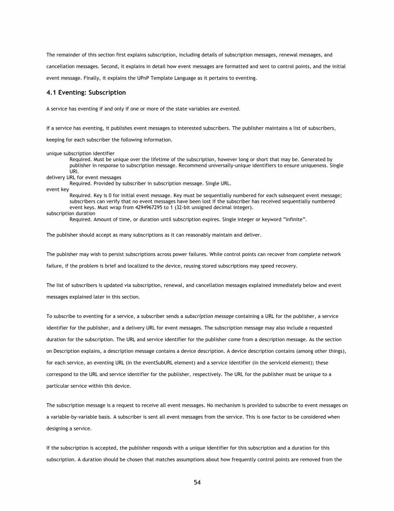
54
The remainder of this section first explains subscription, including details of subscription messages, renewal messages, and
cancellation messages. Second, it explains in detail how event messages are formatted and sent to control points, and the initial
event message. Finally, it explains the UPnP Template Language as it pertains to eventing.
4.1 Eventing: Subscription
A service has eventing if and only if one or more of the state variables are evented.
If a service has eventing, it publishes event messages to interested subscribers. The publisher maintains a list of subscribers,
keeping for each subscriber the following information.
unique subscription identifier Required. Must be unique over the lifetime of the subscription, however long or short that may be. Generated by publisher in response to subscription message. Recommend universally-unique identifiers to ensure uniqueness. Single URI.
delivery URL for event messages Required. Provided by subscriber in subscription message. Single URL.
event key Required. Key is 0 for initial event message. Key must be sequentially numbered for each subsequent event message; subscribers can verify that no event messages have been lost if the subscriber has received sequentially numbered event keys. Must wrap from 4294967295 to 1 (32-bit unsigned decimal integer).
subscription duration Required. Amount of time, or duration until subscription expires. Single integer or keyword “infinite”.
The publisher should accept as many subscriptions as it can reasonably maintain and deliver.
The publisher may wish to persist subscriptions across power failures. While control points can recover from complete network
failure, if the problem is brief and localized to the device, reusing stored subscriptions may speed recovery.
The list of subscribers is updated via subscription, renewal, and cancellation messages explained immediately below and event
messages explained later in this section.
To subscribe to eventing for a service, a subscriber sends a subscription message containing a URL for the publisher, a service
identifier for the publisher, and a delivery URL for event messages. The subscription message may also include a requested
duration for the subscription. The URL and service identifier for the publisher come from a description message. As the section
on Description explains, a description message contains a device description. A device description contains (among other things),
for each service, an eventing URL (in the eventSubURL element) and a service identifier (in the serviceId element); these
correspond to the URL and service identifier for the publisher, respectively. The URL for the publisher must be unique to a
particular service within this device.
The subscription message is a request to receive all event messages. No mechanism is provided to subscribe to event messages on
a variable-by-variable basis. A subscriber is sent all event messages from the service. This is one factor to be considered when
designing a service.
If the subscription is accepted, the publisher responds with a unique identifier for this subscription and a duration for this
subscription. A duration should be chosen that matches assumptions about how frequently control points are removed from the
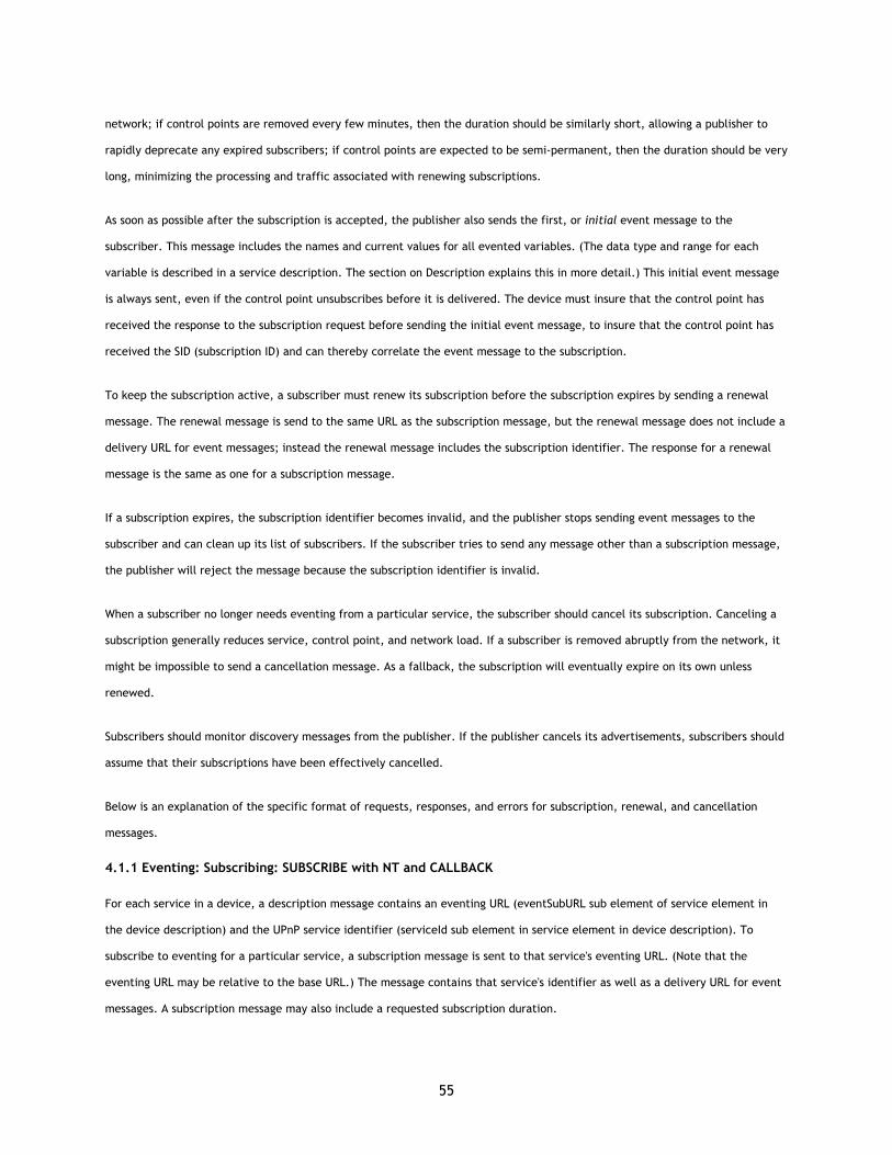
55
network; if control points are removed every few minutes, then the duration should be similarly short, allowing a publisher to
rapidly deprecate any expired subscribers; if control points are expected to be semi-permanent, then the duration should be very
long, minimizing the processing and traffic associated with renewing subscriptions.
As soon as possible after the subscription is accepted, the publisher also sends the first, or initial event message to the
subscriber. This message includes the names and current values for all evented variables. (The data type and range for each
variable is described in a service description. The section on Description explains this in more detail.) This initial event message
is always sent, even if the control point unsubscribes before it is delivered. The device must insure that the control point has
received the response to the subscription request before sending the initial event message, to insure that the control point has
received the SID (subscription ID) and can thereby correlate the event message to the subscription.
To keep the subscription active, a subscriber must renew its subscription before the subscription expires by sending a renewal
message. The renewal message is send to the same URL as the subscription message, but the renewal message does not include a
delivery URL for event messages; instead the renewal message includes the subscription identifier. The response for a renewal
message is the same as one for a subscription message.
If a subscription expires, the subscription identifier becomes invalid, and the publisher stops sending event messages to the
subscriber and can clean up its list of subscribers. If the subscriber tries to send any message other than a subscription message,
the publisher will reject the message because the subscription identifier is invalid.
When a subscriber no longer needs eventing from a particular service, the subscriber should cancel its subscription. Canceling a
subscription generally reduces service, control point, and network load. If a subscriber is removed abruptly from the network, it
might be impossible to send a cancellation message. As a fallback, the subscription will eventually expire on its own unless
renewed.
Subscribers should monitor discovery messages from the publisher. If the publisher cancels its advertisements, subscribers should
assume that their subscriptions have been effectively cancelled.
Below is an explanation of the specific format of requests, responses, and errors for subscription, renewal, and cancellation
messages.
4.1.1 Eventing: Subscribing: SUBSCRIBE with NT and CALLBACK
For each service in a device, a description message contains an eventing URL (eventSubURL sub element of service element in
the device description) and the UPnP service identifier (serviceId sub element in service element in device description). To
subscribe to eventing for a particular service, a subscription message is sent to that service's eventing URL. (Note that the
eventing URL may be relative to the base URL.) The message contains that service's identifier as well as a delivery URL for event
messages. A subscription message may also include a requested subscription duration.
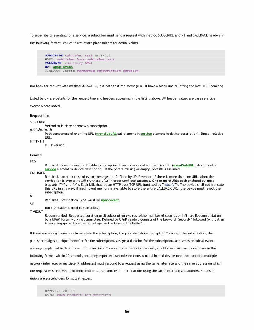
56
To subscribe to eventing for a service, a subscriber must send a request with method SUBSCRIBE and NT and CALLBACK headers in
the following format. Values in italics are placeholders for actual values.
SUBSCRIBE publisher path HTTP/1.1 HOST: publisher host:publisher port CALLBACK: <delivery URL> NT: upnp:event TIMEOUT: Second-requested subscription duration
(No body for request with method SUBSCRIBE, but note that the message must have a blank line following the last HTTP header.)
Listed below are details for the request line and headers appearing in the listing above. All header values are case sensitive
except where noted.
Request line
SUBSCRIBE Method to initiate or renew a subscription.
publisher path Path component of eventing URL (eventSubURL sub element in service element in device description). Single, relative URL.
HTTP/1.1 HTTP version.
Headers
HOST Required. Domain name or IP address and optional port components of eventing URL (eventSubURL sub element in service element in device description). If the port is missing or empty, port 80 is assumed.
CALLBACK Required. Location to send event messages to. Defined by UPnP vendor. If there is more than one URL, when the service sends events, it will try these URLs in order until one succeeds. One or more URLs each enclosed by angle brackets (“<” and “>”). Each URL shall be an HTTP over TCP URL (prefixed by “http://”). The device shall not truncate this URL in any way; if insufficient memory is available to store the entire CALLBACK URL, the device must reject the subscription.
NT Required. Notification Type. Must be upnp:event.
SID (No SID header is used to subscribe.)
TIMEOUT Recommended. Requested duration until subscription expires, either number of seconds or infinite. Recommendation by a UPnP Forum working committee. Defined by UPnP vendor. Consists of the keyword “Second-” followed (without an intervening space) by either an integer or the keyword “infinite”.
If there are enough resources to maintain the subscription, the publisher should accept it. To accept the subscription, the
publisher assigns a unique identifier for the subscription, assigns a duration for the subscription, and sends an initial event
message (explained in detail later in this section). To accept a subscription request, a publisher must send a response in the
following format within 30 seconds, including expected transmission time. A multi-homed device (one that supports multiple
network interfaces or multiple IP addresses) must respond to a request using the same interface and the same address on which
the request was received, and then send all subsequent event notifications using the same interface and address. Values in
italics are placeholders for actual values.
HTTP/1.1 200 OK DATE: when response was generated
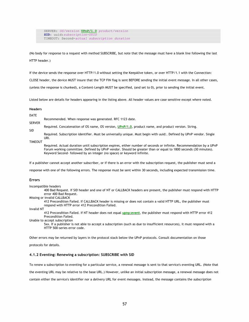
57
SERVER: OS/version UPnP/1.0 product/version SID: uuid:subscription-UUID TIMEOUT: Second-actual subscription duration
(No body for response to a request with method SUBSCRIBE, but note that the message must have a blank line following the last
HTTP header.)
If the device sends the response over HTTP/1.0 without setting the KeepAlive token, or over HTTP/1.1 with the Connection:
CLOSE header, the device MUST insure that the TCP FIN flag is sent BEFORE sending the initial event message. In all other cases,
(unless the response is chunked), a Content-Length MUST be specified, (and set to 0), prior to sending the initial event.
Listed below are details for headers appearing in the listing above. All header values are case sensitive except where noted.
Headers
DATE Recommended. When response was generated. RFC 1123 date.
SERVER Required. Concatenation of OS name, OS version, UPnP/1.0, product name, and product version. String.
SID Required. Subscription identifier. Must be universally unique. Must begin with uuid:. Defined by UPnP vendor. Single URI.
TIMEOUT Required. Actual duration until subscription expires, either number of seconds or infinite. Recommendation by a UPnP Forum working committee. Defined by UPnP vendor. Should be greater than or equal to 1800 seconds (30 minutes). Keyword Second- followed by an integer (no space) or keyword infinite.
If a publisher cannot accept another subscriber, or if there is an error with the subscription request, the publisher must send a
response with one of the following errors. The response must be sent within 30 seconds, including expected transmission time.
Errors
Incompatible headers 400 Bad Request. If SID header and one of NT or CALLBACK headers are present, the publisher must respond with HTTP error 400 Bad Request.
Missing or invalid CALLBACK 412 Precondition Failed. If CALLBACK header is missing or does not contain a valid HTTP URL, the publisher must respond with HTTP error 412 Precondition Failed.
Invalid NT 412 Precondition Failed. If NT header does not equal upnp:event, the publisher must respond with HTTP error 412 Precondition Failed.
Unable to accept subscription 5xx. If a publisher is not able to accept a subscription (such as due to insufficient resources), it must respond with a HTTP 500-series error code.
Other errors may be returned by layers in the protocol stack below the UPnP protocols. Consult documentation on those
protocols for details.
4.1.2 Eventing: Renewing a subscription: SUBSCRIBE with SID
To renew a subscription to eventing for a particular service, a renewal message is sent to that service's eventing URL. (Note that
the eventing URL may be relative to the base URL.) However, unlike an initial subscription message, a renewal message does not
contain either the service's identifier nor a delivery URL for event messages. Instead, the message contains the subscription
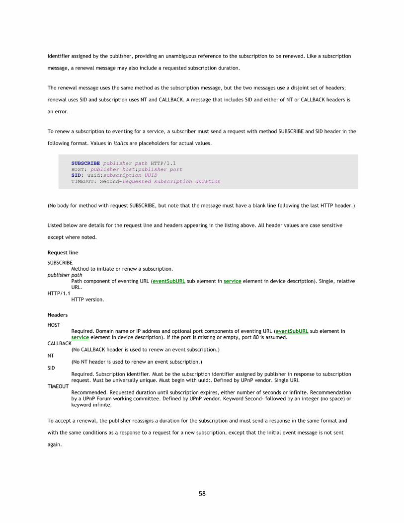
58
identifier assigned by the publisher, providing an unambiguous reference to the subscription to be renewed. Like a subscription
message, a renewal message may also include a requested subscription duration.
The renewal message uses the same method as the subscription message, but the two messages use a disjoint set of headers;
renewal uses SID and subscription uses NT and CALLBACK. A message that includes SID and either of NT or CALLBACK headers is
an error.
To renew a subscription to eventing for a service, a subscriber must send a request with method SUBSCRIBE and SID header in the
following format. Values in italics are placeholders for actual values.
SUBSCRIBE publisher path HTTP/1.1 HOST: publisher host:publisher port SID: uuid:subscription UUID TIMEOUT: Second-requested subscription duration
(No body for method with request SUBSCRIBE, but note that the message must have a blank line following the last HTTP header.)
Listed below are details for the request line and headers appearing in the listing above. All header values are case sensitive
except where noted.
Request line
SUBSCRIBE Method to initiate or renew a subscription.
publisher path Path component of eventing URL (eventSubURL sub element in service element in device description). Single, relative URL.
HTTP/1.1 HTTP version.
Headers
HOST Required. Domain name or IP address and optional port components of eventing URL (eventSubURL sub element in service element in device description). If the port is missing or empty, port 80 is assumed.
CALLBACK (No CALLBACK header is used to renew an event subscription.)
NT (No NT header is used to renew an event subscription.)
SID Required. Subscription identifier. Must be the subscription identifier assigned by publisher in response to subscription request. Must be universally unique. Must begin with uuid:. Defined by UPnP vendor. Single URI.
TIMEOUT Recommended. Requested duration until subscription expires, either number of seconds or infinite. Recommendation by a UPnP Forum working committee. Defined by UPnP vendor. Keyword Second- followed by an integer (no space) or keyword infinite.
To accept a renewal, the publisher reassigns a duration for the subscription and must send a response in the same format and
with the same conditions as a response to a request for a new subscription, except that the initial event message is not sent
again.

59
If a publisher cannot accept the renewal, or if there is an error with the renewal request, the publisher must send a response
with one of the following errors. The response must be sent within 30 seconds, including expected transmission time. A multi-
homed device (one that supports multiple network interfaces or multiple IP addresses) must respond to a request using the same
interface and the same address on which the request was received.
Errors
Incompatible headers 400 Bad Request. If SID header and one of NT or CALLBACK headers are present, the publisher must respond with HTTP error 400 Bad Request.
Invalid SID 412 Precondition Failed. If a SID does not correspond to a known, un-expired subscription, the publisher must respond with HTTP error 412 Precondition Failed.
Missing SID 412 Precondition Failed. If the SID header is missing or empty, the publisher must respond with HTTP error 412 Precondition Failed.
Unable to accept renewal 5xx. If the publisher is not able to accept a renewal, it must respond with a HTTP 500-series error code.
Other errors may be returned by layers in the protocol stack below the UPnP protocols. Consult documentation on those
protocols for details.
4.1.3 Eventing: Canceling a subscription: UNSUBSCRIBE
When eventing is no longer needed from a particular service, a cancellation message should be sent to that service's eventing
URL. (Note that the eventing URL may be relative to the base URL.) The message contains the subscription identifier. Canceling a
subscription generally reduces service, control point, and network load. If a control point is removed abruptly from the network,
it might be impossible to send a cancellation message. As a fallback, the subscription will eventually expire on its own unless
renewed.
To cancel a subscription to eventing for a service, a subscriber should send a request with method UNSUBSCRIBE in the following
format. Values in italics are placeholders for actual values.
UNSUBSCRIBE publisher path HTTP/1.1 HOST: publisher host:publisher port SID: uuid:subscription UUID
(No body for request with method UNSUBSCRIBE, but note that the message must have a blank line following the last HTTP
header.)
Listed below are details for the request line and headers appearing in the listing above. All header values are case sensitive
except where noted.
Request line
UNSUBSCRIBE Method to cancel a subscription.
publisher path Path component of eventing URL (eventSubURL sub element in service element in device description). Single, relative URL.
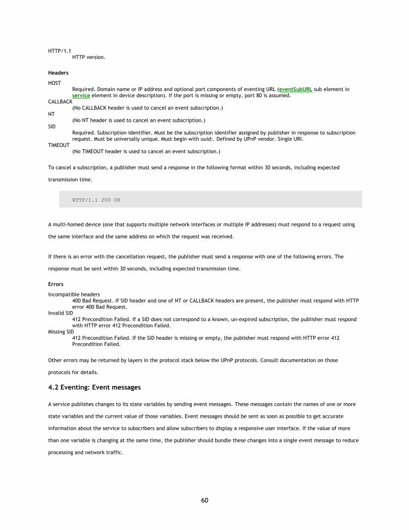
60
HTTP/1.1 HTTP version.
Headers
HOST Required. Domain name or IP address and optional port components of eventing URL (eventSubURL sub element in service element in device description). If the port is missing or empty, port 80 is assumed.
CALLBACK (No CALLBACK header is used to cancel an event subscription.)
NT (No NT header is used to cancel an event subscription.)
SID Required. Subscription identifier. Must be the subscription identifier assigned by publisher in response to subscription request. Must be universally unique. Must begin with uuid:. Defined by UPnP vendor. Single URI.
TIMEOUT (No TIMEOUT header is used to cancel an event subscription.)
To cancel a subscription, a publisher must send a response in the following format within 30 seconds, including expected
transmission time.
HTTP/1.1 200 OK
A multi-homed device (one that supports multiple network interfaces or multiple IP addresses) must respond to a request using
the same interface and the same address on which the request was received.
If there is an error with the cancellation request, the publisher must send a response with one of the following errors. The
response must be sent within 30 seconds, including expected transmission time.
Errors
Incompatible headers 400 Bad Request. If SID header and one of NT or CALLBACK headers are present, the publisher must respond with HTTP error 400 Bad Request.
Invalid SID 412 Precondition Failed. If a SID does not correspond to a known, un-expired subscription, the publisher must respond with HTTP error 412 Precondition Failed.
Missing SID 412 Precondition Failed. If the SID header is missing or empty, the publisher must respond with HTTP error 412 Precondition Failed.
Other errors may be returned by layers in the protocol stack below the UPnP protocols. Consult documentation on those
protocols for details.
4.2 Eventing: Event messages
A service publishes changes to its state variables by sending event messages. These messages contain the names of one or more
state variables and the current value of those variables. Event messages should be sent as soon as possible to get accurate
information about the service to subscribers and allow subscribers to display a responsive user interface. If the value of more
than one variable is changing at the same time, the publisher should bundle these changes into a single event message to reduce
processing and network traffic.
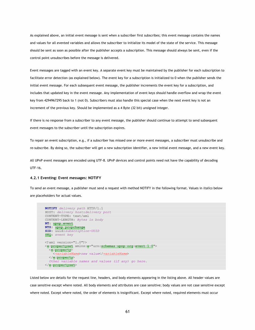
61
As explained above, an initial event message is sent when a subscriber first subscribes; this event message contains the names
and values for all evented variables and allows the subscriber to initialize its model of the state of the service. This message
should be sent as soon as possible after the publisher accepts a subscription. This message should always be sent, even if the
control point unsubscribes before the message is delivered.
Event messages are tagged with an event key. A separate event key must be maintained by the publisher for each subscription to
facilitate error detection (as explained below). The event key for a subscription is initialized to 0 when the publisher sends the
initial event message. For each subsequent event message, the publisher increments the event key for a subscription, and
includes that updated key in the event message. Any implementation of event keys should handle overflow and wrap the event
key from 4294967295 back to 1 (not 0). Subscribers must also handle this special case when the next event key is not an
increment of the previous key. Should be implemented as a 4 Byte (32 bit) unsigned integer.
If there is no response from a subscriber to any event message, the publisher should continue to attempt to send subsequent
event messages to the subscriber until the subscription expires.
To repair an event subscription, e.g., if a subscriber has missed one or more event messages, a subscriber must unsubscribe and
re-subscribe. By doing so, the subscriber will get a new subscription identifier, a new initial event message, and a new event key.
All UPnP event messages are encoded using UTF-8. UPnP devices and control points need not have the capability of decoding
UTF-16.
4.2.1 Eventing: Event messages: NOTIFY
To send an event message, a publisher must send a request with method NOTIFY in the following format. Values in italics below
are placeholders for actual values.
NOTIFY delivery path HTTP/1.1 HOST: delivery host:delivery port CONTENT-TYPE: text/xml CONTENT-LENGTH: Bytes in body NT: upnp:event NTS: upnp:propchange SID: uuid:subscription-UUID SEQ: event key <?xml version="1.0"?> <e:propertyset xmlns:e="urn:schemas-upnp-org:event-1-0"> <e:property> <variableName>new value</variableName> </e:property> Other variable names and values (if any) go here. </e:propertyset>
Listed below are details for the request line, headers, and body elements appearing in the listing above. All header values are
case sensitive except where noted. All body elements and attributes are case sensitive; body values are not case sensitive except
where noted. Except where noted, the order of elements is insignificant. Except where noted, required elements must occur
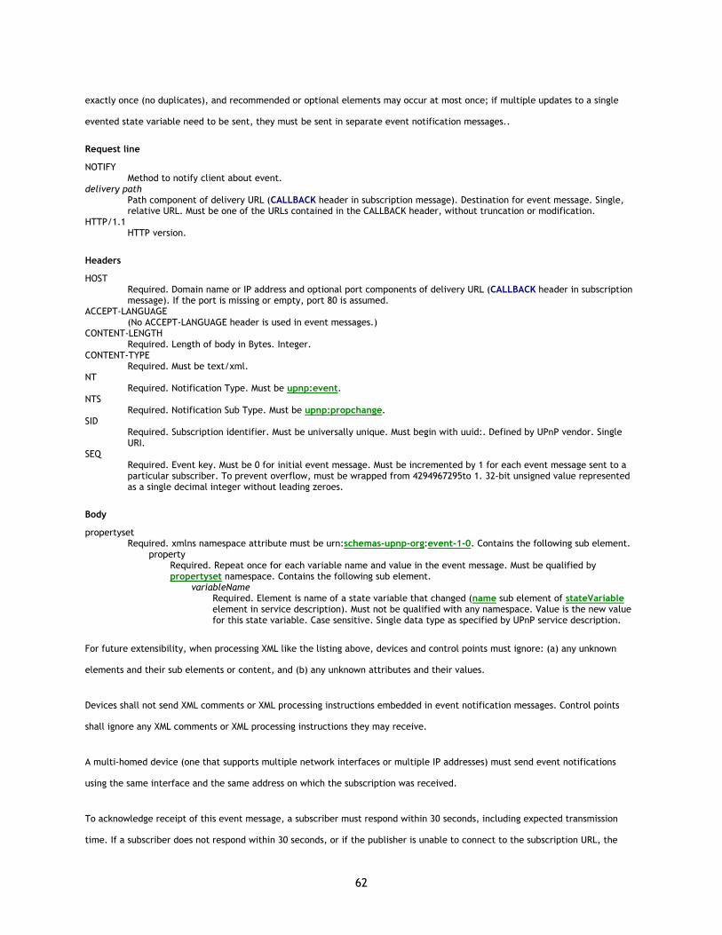
62
exactly once (no duplicates), and recommended or optional elements may occur at most once; if multiple updates to a single
evented state variable need to be sent, they must be sent in separate event notification messages..
Request line
NOTIFY Method to notify client about event.
delivery path Path component of delivery URL (CALLBACK header in subscription message). Destination for event message. Single, relative URL. Must be one of the URLs contained in the CALLBACK header, without truncation or modification.
HTTP/1.1 HTTP version.
Headers
HOST Required. Domain name or IP address and optional port components of delivery URL (CALLBACK header in subscription message). If the port is missing or empty, port 80 is assumed.
ACCEPT-LANGUAGE (No ACCEPT-LANGUAGE header is used in event messages.)
CONTENT-LENGTH Required. Length of body in Bytes. Integer.
CONTENT-TYPE Required. Must be text/xml.
NT Required. Notification Type. Must be upnp:event.
NTS Required. Notification Sub Type. Must be upnp:propchange.
SID Required. Subscription identifier. Must be universally unique. Must begin with uuid:. Defined by UPnP vendor. Single URI.
SEQ Required. Event key. Must be 0 for initial event message. Must be incremented by 1 for each event message sent to a particular subscriber. To prevent overflow, must be wrapped from 4294967295to 1. 32-bit unsigned value represented as a single decimal integer without leading zeroes.
Body
propertyset Required. xmlns namespace attribute must be urn:schemas-upnp-org:event-1-0. Contains the following sub element.
property Required. Repeat once for each variable name and value in the event message. Must be qualified by propertyset namespace. Contains the following sub element.
variableName Required. Element is name of a state variable that changed (name sub element of stateVariable element in service description). Must not be qualified with any namespace. Value is the new value for this state variable. Case sensitive. Single data type as specified by UPnP service description.
For future extensibility, when processing XML like the listing above, devices and control points must ignore: (a) any unknown
elements and their sub elements or content, and (b) any unknown attributes and their values.
Devices shall not send XML comments or XML processing instructions embedded in event notification messages. Control points
shall ignore any XML comments or XML processing instructions they may receive.
A multi-homed device (one that supports multiple network interfaces or multiple IP addresses) must send event notifications
using the same interface and the same address on which the subscription was received.
To acknowledge receipt of this event message, a subscriber must respond within 30 seconds, including expected transmission
time. If a subscriber does not respond within 30 seconds, or if the publisher is unable to connect to the subscription URL, the
63
publisher should abandon sending this message to the subscriber but should keep the subscription active and send future event
messages to the subscriber until the subscription expires or is cancelled. The subscriber must send a response in the following
format.
HTTP/1.1 200 OK
(No body for a request with method NOTIFY, but note that the message must have a blank line following the last HTTP header.)
If a device sends an event to a control point using HTTP/1.0 without the KeepAlive token, the Control Point MUST close the
socket after responding. If a device sends an event to a control point using HTTP/1.1 and sets the Connection: CLOSE token, the
Control Point MUST close the socket after responding.
If there is an error with the event message, the subscriber must respond with one of the following errors. The response must be
sent within 30 seconds, including expected transmission time.
Errors
Missing SID 412 Precondition Failed. If the SID header is missing or empty, the subscriber must respond with HTTP error 412 Precondition Failed.
Invalid SID 412 Precondition Failed. If a SID does not correspond to a known subscription, the subscriber must respond with HTTP error 412 Precondition Failed. (Service must terminate this SID when it receives this error response.)
Missing NT or NTS header 400 Bad Request. If the NT or NTS header is missing, the subscriber must respond with HTTP error 400 Bad Request.
Invalid NT header 412 Precondition Failed. If NT header does not equal upnp:event, the subscriber must respond with HTTP error 412 Precondition Failed.
Invalid NTS header 412 Precondition Failed. If NTS header does not equal upnp:propchange, the subscriber must respond with HTTP error 412 Precondition Failed.
Other errors may be returned by layers in the protocol stack below the UPnP protocols. Consult documentation on those
protocols for details.
4.3 Eventing: UPnP Template Language for eventing
The UPnP Template Language defines well-formed templates for devices and services. To a lesser extent, it also provides a
template for the body of event messages. The section on Description explains the UPnP Template Language as it pertains to
devices and services. As explained in that section, the UPnP Template Language is written in XML syntax and is derived from XML
Schema (Part 1: Structures, Part 2: Datatypes). Below is a listing of this language as it pertains to eventing. The elements it
defines are used in event messages; they are colored green here, and they are colored green in the listing above. Below is where
these elements are defined (though it is a minimal definition); above is where they are used.
Immediately following this is a brief explanation of the XML Schema elements, attributes, and values used. The reference to XML
Schema at the end of this section has further details.
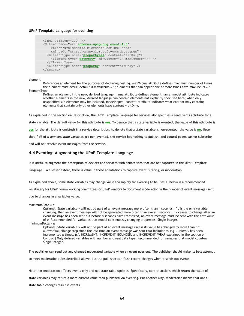
64
UPnP Template Language for eventing
<?xml version="1.0" ?> <Schema name="urn:schemas-upnp-org:event-1-0" xmlns="urn:schemas-microsoft-com:xml-data" xmlns:dt="urn:schemas-microsoft-com:datatypes"> <ElementType name="propertyset" content="eltOnly"> <element type="property" minOccurs="1" maxOccurs="*" /> </ElementType> <ElementType name="property" content="eltOnly" /> </Schema>
element
References an element for the purposes of declaring nesting. maxOccurs attribute defines maximum number of times the element must occur; default is maxOccurs = 1; elements that can appear one or more times have maxOccurs = *.
ElementType Defines an element in the new, derived language. name attribute defines element name. model attribute indicates whether elements in the new, derived language can contain elements not explicitly specified here; when only unspecified sub elements may be included, model=open. content attribute indicates what content may contain; elements that contain only other elements have content = eltOnly.
As explained in the section on Description, the UPnP Template Language for services also specifies a sendEvents attribute for a
state variable. The default value for this attribute is yes. To denote that a state variable is evented, the value of this attribute is
yes (or the attribute is omitted) in a service description; to denote that a state variable is non-evented, the value is no. Note
that if all of a service's state variables are non-evented, the service has nothing to publish, and control points cannot subscribe
and will not receive event messages from the service.
4.4 Eventing: Augmenting the UPnP Template Language
It is useful to augment the description of devices and services with annotations that are not captured in the UPnP Template
Language. To a lesser extent, there is value in these annotations to capture event filtering, or moderation.
As explained above, some state variables may change value too rapidly for eventing to be useful. Below is a recommended
vocabulary for UPnP Forum working committees or UPnP vendors to document moderation in the number of event messages sent
due to changes in a variables value.
maximumRate = n Optional. State variable v will not be part of an event message more often than n seconds. If v is the only variable changing, then an event message will not be generated more often than every n seconds. If v ceases to change after an event message has been sent but before n seconds have transpired, an event message must be sent with the new value of v. Recommended for variables that model continuously changing properties. Single integer.
minimumDelta = n Optional. State variable v will not be part of an event message unless its value has changed by more than n * allowedValueRange step since the last time an event message was sent that included v, e.g., unless v has been incremented n times. (cf. INCREMENT, INCREMENT_BOUNDED, and INCREMENT_WRAP explained in the section on Control.) Only defined variables with number and real data type. Recommended for variables that model counters. Single integer.
The publisher can send out any changed moderated variable when an event goes out. The publisher should make its best attempt
to meet moderation rules described above, but the publisher can flush recent changes when it sends out events.
Note that moderation affects events only and not state table updates. Specifically, control actions which return the value of
state variables may return a more current value than published via eventing. Put another way, moderation means that not all
state table changes result in events.
65
Decisions about which variables to event and any possible moderation is up to the appropriate UPnP Forum working committee
(for standard services) or a UPnP vendor (for non-standard services).
4.5 Eventing references
XML Schema (Part 1: Structures, Part 2: Datatypes) Grammar defining UPnP Template Language. <http://www.w3.org/TR/xmlschema-1>, <http://www.w3.org/TR/xmlschema-2>.
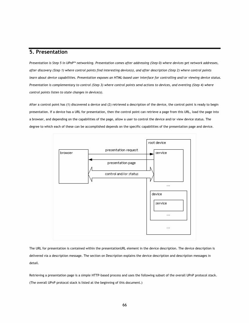
66
5. Presentation
Presentation is Step 5 in UPnP™ networking. Presentation comes after addressing (Step 0) where devices get network addresses,
after discovery (Step 1) where control points find interesting device(s), and after description (Step 2) where control points
learn about device capabilities. Presentation exposes an HTML-based user interface for controlling and/or viewing device status.
Presentation is complementary to control (Step 3) where control points send actions to devices, and eventing (Step 4) where
control points listen to state changes in device(s).
After a control point has (1) discovered a device and (2) retrieved a description of the device, the control point is ready to begin
presentation. If a device has a URL for presentation, then the control point can retrieve a page from this URL, load the page into
a browser, and depending on the capabilities of the page, allow a user to control the device and/or view device status. The
degree to which each of these can be accomplished depends on the specific capabilities of the presentation page and device.
The URL for presentation is contained within the presentationURL element in the device description. The device description is
delivered via a description message. The section on Description explains the device description and description messages in
detail.
Retrieving a presentation page is a simple HTTP-based process and uses the following subset of the overall UPnP protocol stack.
(The overall UPnP protocol stack is listed at the beginning of this document.)
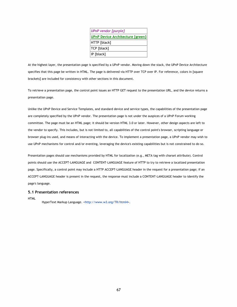
67
UPnP vendor [purple]
UPnP Device Architecture [green]
HTTP [black]
TCP [black]
IP [black]
At the highest layer, the presentation page is specified by a UPnP vendor. Moving down the stack, the UPnP Device Architecture
specifies that this page be written in HTML. The page is delivered via HTTP over TCP over IP. For reference, colors in [square
brackets] are included for consistency with other sections in this document.
To retrieve a presentation page, the control point issues an HTTP GET request to the presentation URL, and the device returns a
presentation page.
Unlike the UPnP Device and Service Templates, and standard device and service types, the capabilities of the presentation page
are completely specified by the UPnP vendor. The presentation page is not under the auspices of a UPnP Forum working
committee. The page must be an HTML page; it should be version HTML 3.0 or later. However, other design aspects are left to
the vendor to specify. This includes, but is not limited to, all capabilities of the control point's browser, scripting language or
browser plug-ins used, and means of interacting with the device. To implement a presentation page, a UPnP vendor may wish to
use UPnP mechanisms for control and/or eventing, leveraging the device's existing capabilities but is not constrained to do so.
Presentation pages should use mechanisms provided by HTML for localization (e.g., META tag with charset attribute). Control
points should use the ACCEPT-LANGUAGE and CONTENT-LANGUAGE feature of HTTP to try to retrieve a localized presentation
page. Specifically, a control point may include a HTTP ACCEPT-LANGUAGE header in the request for a presentation page; if an
ACCEPT-LANGUAGE header is present in the request, the response must include a CONTENT-LANGUAGE header to identify the
page's language.
5.1 Presentation references
HTML HyperText Markup Language. <http://www.w3.org/TR/html4>.

68
A. IP Version 6 Support
A.1 Introduction
Most of today's internet uses IPv4, which is now nearly twenty years old. IPv4 has been remarkably resilient in spite of its age,
but it is beginning to have problems. Most importantly, there is a growing shortage of IPv4 addresses, which are needed by all
new machines added to the Internet. Deployment of large numbers of UPnP™ devices will only exacerbate the shortage.
IPv6 fixes a number of problems in IPv4, such as the limited number of available IPv4 addresses. It also adds many improvements
to IPv4 in areas such as routing and network autoconfiguration. IPv6 is expected to gradually replace IPv4, with the two
coexisting for a number of years during a transition period.
This Annex describes mechanisms by which devices based on the UPnP Device Architecture may be used on IPv6 networks.
A.2 General Principles
Devices using the UPnP Device Architecture over IPv6:
• MUST support link-local addresses and scopes as the default configuration. This means listening and broadcasting on
FF02::C, the link-local scope multicast address for SSDP.
• MUST use scoping of IPv6 addresses to control the propagation of SSDP messages instead of relying on the Hop Limit
(equivalent to the TTL limit in IPv4).
• MAY support subnet scope FF03::C, administrative scope FF04::C and site-local scope FF05::C as a configurable
option. If one of these scopes is selected, the device will support it in addition to the link-local scope.
• MAY provide the ability to select which interface or interfaces over which the device will be visible to UPnP control
points, in devices that support multiple interfaces.
• MAY use the Network Location Signature (NLS), described later in this document, to carry a unique signature for the
networking state of the device. If implemented, the NLS MUST change each time the network addresses over which the
device is visible to UPnP control points change in the device, so that control points can recognize when a received
advertisement represents a duplicate of one received on a different stack or address rather than an indication that the
device has received a new address and the old one should be disregarded. Every announcement on every scope, site,
and interface includes the same NLS value.
69
A.2.1 Link-local scope
Link-local scope SHALL be the default scope for operation over IPv6. The device will choose the set of link-local addresses to be
used. The default value is one link-local address per interface. In case more than one link-local address is available for any
particular interface, one of the addresses is selected and used for that interface; devices SHOULD use the same address as
previously used whenever possible.
A.2.2 Site-local scope
Site-local addresses and scopes MAY also be supported in UPnP devices. If supported and enabled, the administrator SHALL
specify the scope(s) in which the UPnP device is to be active. If the scope is not otherwise specified, the default value SHALL be
to use link-local scope only.
If site-local scope support is enabled, during initialization the device SHALL attempt to obtain a site-local address by sending a
Router Solicitation message and then executing a site-local address configuration sequence. Unless a particular subset of
interfaces is specified by the administrator or device default, UPnP operation SHALL be enabled on all interfaces. If more than
one site-local address is available on any particular interface, or across a set of interfaces, and they are all valid in the same site
for the specified scope, then one site-local address SHALL be selected and used as the IP source address and LOCATION for UPnP
operations on the interface(s) on which the address is valid; devices SHOULD use the same address as previously used whenever
possible. If site-local addresses belong to two or more different sites, then one site-local address SHALL be selected for each site.
The NLS value, if provided, SHALL be the same across all networks, sites, addresses, and interfaces.
Up to three announcements are sent per interface, one using the IPv4 address, the second using the link-local IPv6 address, and
the third using the site-local address, if enabled.
A.2.3 Device operation
A device supporting both IPv4 and IPv6 simultaneously SHALL be advertised using the same USN on both IPv4 and IPv6 only if the
device description document and presentation resources are identical when accessed from both protocols. If there is any
difference in the description of the device or its services when operating on IPv6 versus IPv4, the device SHALL NOT be
advertised with the same USN on both networks; instead, it SHALL be advertised as two separate devices with distinct USN values.
It is the responsibility of the device to determine the services to be advertised on each of the addresses. For example,
advertising certain Internet Gateway features on IPv6 addresses may not be useful, in which case the device should not do it.
(Throughout the remainder of this Annex, a single physical device which contains two or more “logical” devices that have
different USNs is considered to be separate devices.)
A.2.4 Control point operation
A UPnP device which advertises on multiple networks, multiple addresses, or multiple interfaces SHOULD be displayed only once
in the control point user interface in order to reduce user confusion. Control points typically use the LOCATION and USN headers
to identify and discard duplicate advertisements, but this may not be sufficient when a control point supporting multiple
70
networks, addresses, or interfaces receives announcements from a device which also supports multiple networks, address, or
interfaces - the USNs will still match, but the location URL may be different (each may contain a different literal numeric IP
address). In this case, if the device follows the guidelines above, the NLS header values will match across all networks, address,
and interfaces, allowing the control point to properly determine that the device is accessible through multiple LOCATIONs rather
than having changed LOCATION.
The control point MAY use any of the URLs received in LOCATION headers to access the device - the device description or
presentation page - on the local network.
Regardless of which way, from what address, and how many announcements a control point receives, it will unambiguously know
that they were sent by the same device, so long as the device properly implements the NLS header.
A device BYE-BYE message received on either IPv4 or IPv6 SHOULD cause all instances of the device to be removed from the
control point cache of known devices.
A.3 Addressing
UDA version 1.0 devices MAY support IPv4, IPv6, or both. The following sections describe how a device obtains an IPv6 address.
The mechanisms described do not differ in any significant way from those described in the IPv6 standards. Note that in most
implementations, the actions described are likely performed by the IPv6 stack and do not require any special coding by UPnP
implementers.
Unlike when using IPv4, where each device must have a DHCP client to try to obtain an address initially, DHCP is unnecessary in
an IPv6 network. Addresses are automatically configured in new ways.
In IPv6 networks, link-local addresses are determined per interface on the device, and therefore IPv6 devices will always have a
link-local address. In addition, unicast addresses (site local or global addresses), and the loopback address ::1 are also
determined for each interface although a device may or may not have a site-local or global address. Typical IPv6 devices are
logically multi-homed because they always have at least two addresses with which they can receive packets – a link-local address
for local link traffic and a routable site-local or global address. In some scenarios, devices may only have a link-local address;
reasons for this include device sophistication (and thereby device capability) and administrative policy. Link-local addresses are
assigned immediately at the device, without referring to an outside server such as a DHCP server. Site-local and global addresses
are determined through the use of RA (Router Advertisement) messages in conversation with the local router. With site
multihoming, source address selection rules are complicated.
The UPnP architecture exploits IPv6 link-local and site-local addresses. Link-local addresses are used between on-same-link
neighbors (and in IPv6’s own Neighbor Discovery process). Site-local addresses are used between nodes communicating with other
nodes in the same site.
71
This section describes the IPv6 autoconfiguration of link-local and site-local addresses in more detail. In addition to the address
assigned by this process, each device, acting as a normal IPv6 host, listens for traffic on several multicast addresses: node-local
scope all-nodes multicast address FF01::1; link-local scope all-nodes multicast address FF02::1; and multicast addresses of
joined groups on each interface.
A.3.1 IPv6 link-local address autoconfiguration
Link-local addresses use a FE80::/64 prefix. The IPv6 link-local address autoconfiguration process is summarized as follows:
1. A tentative link-local address is derived at the device by local automatic assignment.
2. Duplicate address detection is performed on the link.
3. If not unique, manual configuration of the link-local address is required.
4. If unique, the tentative link-local address is reset to “valid”.
5. Other autoconfiguration steps take place.
The details of this process are described below.
1. A tentative link-local address is derived at the device based on the link-local prefix of FE80::/64 and concatenating
that with the 64 bit interface identifier for each interface on the device. The interface identifier is generally based on
a unique token derived from the MAC address, such as the IEEE EUI-64 number. This tentative address is assigned a
formal state of “tentative”.
2. Duplicate address detection is performed by the device to verify the uniqueness of the tentative link-local address.
This is done by sending a Neighbor Solicitation (NS) ICMPv6 message to the network (local link) with its Target Address
field set to the tentative link-local address of the device. Multiple NS messages are sent, to ensure conflict detection.
3. If a Neighbor Advertisement ICMPv6 message sent in response to the Neighbor Solicitation message is received, this
indicates that another device on the local link is already using the tentative link-local address, and autoconfiguration
must stop. At this point, it is conventional to assume that manual configuration of the device’s address must be
performed. However, this is an infrequent case due to the algorithm used to create the tentative addresses. For
example, this is often based on an augmented or processed version of the device’s interface’s MAC address, which is
rarely duplicated. Note there is no standard way to create the tentative address, but the MAC-based algorithm is
common. Further, devices may attempt to generate random interface IDs (limited to several retries to avoid never-
ending attempts before declaring failure).

72
4. If no Neighbor Advertisement message (sent in response to the Neighbor Solicitation message) is received, the tentative
link-local address is assumed to be unique and valid on that link. The link-local address is initialized for the interface
and its state changed from “tentative” to “valid”.
5. The solicited-node multicast link-layer address corresponding to this new valid address is also registered with the
network adapter. Then autoconfiguration proceeds to perform stateless address autoconfiguration with Router
Solicitation and Router Advertisements (see site-local autoconfiguration process in the next section).
The lifetime of link-local addresses is unlimited. If a site-local address is later configured, the link-local address may continue to
be used when appropriate.
A.3.2 IPv6 site-local address autoconfiguration
Site-local addresses use a FEC0::/48 prefix. The IPv6 site-local address autoconfiguration process is part of the general non-
link-local address autoconfiguration process using Router Solicitation and Router Advertisement messages, and is summarized as
follows:
1. A Router Solicitation ICMPv6 message is sent on the local link.
2. If no Router Advertisement ICMPv6 messages are received, alternative address configuration must be performed.
3. If a Router Advertisement message is received, configuration parameters are set.
4. For each Prefix information received, including the site-local prefix, flags are checked and the prefix is processed
accordingly. If appropriate, a tentative address is established (including a tentative site-local address), checked for
duplication, and if not already in use, assigned to be “valid”.
5. The Managed Address Configuration flag is checked.
6. The Other Stateful Configuration flag is checked.
The following provides details of this process.
1. Following the link-local process described earlier, the device sends a Router Solicitation ICMPv6 message to discover
any router on the local link.
2. If no Router Advertisement ICMPv6 messages are received in response, then the device must use an alternative address
configuration protocol to obtain its other addresses and certain other configuration parameters, or use only the link-
local address previously configured.
73
3. If a Router Advertisement message is received, certain configuration parameters are set (Hop Limit, Reachable Time,
Retrans Timer, MTU) using the information carried in the message.
4. For each Prefix information received from the router in the RA message, which may include the site-local prefix:
a. If the On-link flag is set to 1, the prefix is added to the device’s prefix list.
b. If the Autonomous flag is set to 1, the prefix and the 64-bit interface identified are used to derive a tentative
address.
c. Duplicate address detection is used to verify the uniqueness of the tentative address similarly to the link-
local process.
d. If the tentative address is already in use, it is not used.
e. If the tentative address is not in use, the address is initialized (which includes setting the valid and preferred
lifetime values for this address, plus registering the corresponding solicited-node multicast link-layer address
with the network adapter).
5. If the Managed Address Configuration flag is set to 1 in the RA message, a stateful address configuration protocol must
be used to obtain additional addresses.
6. If the Other Stateful Configuration flag is set to 1, a stateful address configuration protocol must be used to obtain
additional configuration parameters.
A.3.3 IPv6 addresses and ports
UPnP devices and control points SHALL support:
• One link-local unicast address per IPv6 interface
• A unicast loopback address ::1 for the loopback interface
• A node-local scope all-nodes multicast address FF01::1
• A link-local scope all-nodes multicast address FF02::1
• The link-local scope multicast address for SSDP [FF02::C]:1900
UPnP devices and control points MAY support:
• One site-local unicast address per site (if a router is present and so configured)
74
• Additional multicast addresses for joined groups.
• The multicast address for SSDP for other scopes in which the device is active [FF0X::C]:1900 (with “X” being set
appropriately depending on the address scope upon with the announcement is being sent)
A.3.4 Summary of boot/startup process
• For IPv4, Auto-IP addressing is done as specified in section 0 of this document.
o Since DNS is not required to be present on the network, implementations typically use literal addresses.
• For IPv6, the device enumerates all interfaces and checks its stored configuration for scope and interface settings.
• For each IPv6 interface, the device invokes the IPv6 auto-configuration process
o Derive tentative link-local address (FE80::/64 + 64 bit Interface ID)
o Send multicast neighbor solicitation to ensure link-local uniqueness
If a reply is received, the IPv6 auto-configuration sequence stops and manual configuration is
normally required (although provision may be made for attempting randomly-generated addresses).
o Initialize link-local address
o If site-local scope specified, attempt to obtain a site-local address
Send a router solicitation message
Execute site-local address configuration sequence.
A.4 Discovery
The UPnP discovery phase does not substantially change when used over IPv6. IP Addresses embedded in UPnP messages and
descriptions sent in response to requests received on IPv6 addresses will generally be literal addresses formatted according to
RFC 2732 (including those in discovery messages, the URLBase element of the device description (if specified), and HTTP HOST
headers). The NLS header is added to SSDP to allow control points to recognize when a message received on a different protocol
or address is referring to the same device as opposed to being a new advertisement from a device whose address has changed.
A.4.1 Advertisement
For IPv6, a device advertises according to the following guidelines:
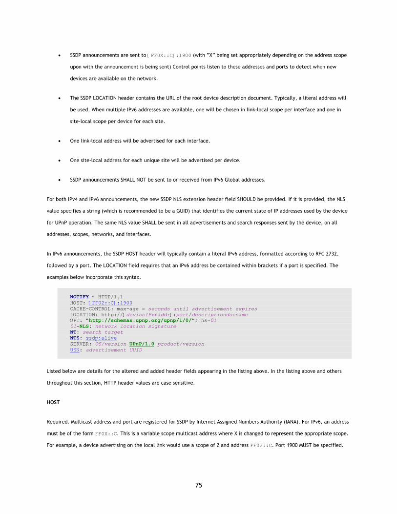
75
• SSDP announcements are sent to [FF0X::C]:1900 (with “X” being set appropriately depending on the address scope
upon with the announcement is being sent) Control points listen to these addresses and ports to detect when new
devices are available on the network.
• The SSDP LOCATION header contains the URL of the root device description document. Typically, a literal address will
be used. When multiple IPv6 addresses are available, one will be chosen in link-local scope per interface and one in
site-local scope per device for each site.
• One link-local address will be advertised for each interface.
• One site-local address for each unique site will be advertised per device.
• SSDP announcements SHALL NOT be sent to or received from IPv6 Global addresses.
For both IPv4 and IPv6 announcements, the new SSDP NLS extension header field SHOULD be provided. If it is provided, the NLS
value specifies a string (which is recommended to be a GUID) that identifies the current state of IP addresses used by the device
for UPnP operation. The same NLS value SHALL be sent in all advertisements and search responses sent by the device, on all
addresses, scopes, networks, and interfaces.
In IPv6 announcements, the SSDP HOST header will typically contain a literal IPv6 address, formatted according to RFC 2732,
followed by a port. The LOCATION field requires that an IPv6 address be contained within brackets if a port is specified. The
examples below incorporate this syntax.
NOTIFY * HTTP/1.1 HOST: [FF02::C]:1900 CACHE-CONTROL: max-age = seconds until advertisement expires LOCATION: http://[deviceIPv6addr]:port/descriptiondocname OPT: "http://schemas.upnp.org/upnp/1/0/"; ns=01 01-NLS: network location signature NT: search target NTS: ssdp:alive SERVER: OS/version UPnP/1.0 product/version USN: advertisement UUID
Listed below are details for the altered and added header fields appearing in the listing above. In the listing above and others
throughout this section, HTTP header values are case sensitive.
HOST
Required. Multicast address and port are registered for SSDP by Internet Assigned Numbers Authority (IANA). For IPv6, an address
must be of the form FF0X::C. This is a variable scope multicast address where X is changed to represent the appropriate scope.
For example, a device advertising on the local link would use a scope of 2 and address FF02::C. Port 1900 MUST be specified.
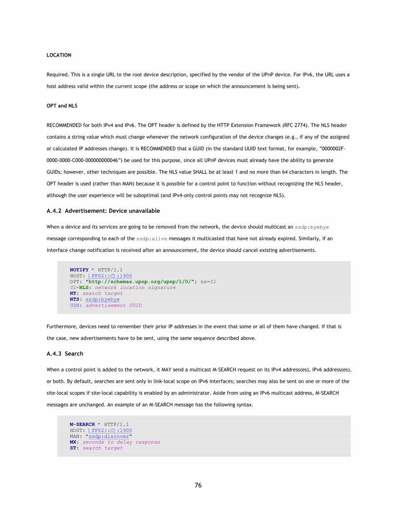
76
LOCATION
Required. This is a single URL to the root device description, specified by the vendor of the UPnP device. For IPv6, the URL uses a
host address valid within the current scope (the address or scope on which the announcement is being sent).
OPT and NLS
RECOMMENDED for both IPv4 and IPv6. The OPT header is defined by the HTTP Extension Framework (RFC 2774). The NLS header
contains a string value which must change whenever the network configuration of the device changes (e.g., if any of the assigned
or calculated IP addresses change). It is RECOMMENDED that a GUID (in the standard UUID text format, for example, “0000002F-
0000-0000-C000-000000000046”) be used for this purpose, since all UPnP devices must already have the ability to generate
GUIDs; however, other techniques are possible. The NLS value SHALL be at least 1 and no more than 64 characters in length. The
OPT header is used (rather than MAN) because it is possible for a control point to function without recognizing the NLS header,
although the user experience will be suboptimal (and IPv4-only control points may not recognize NLS).
A.4.2 Advertisement: Device unavailable
When a device and its services are going to be removed from the network, the device should multicast an ssdp:byebye
message corresponding to each of the ssdp:alive messages it multicasted that have not already expired. Similarly, if an
interface change notification is received after an announcement, the device should cancel existing advertisements.
NOTIFY * HTTP/1.1 HOST: [FF02::C]:1900 OPT: "http://schemas.upnp.org/upnp/1/0/"; ns=01 01-NLS: network location signature NT: search target NTS: ssdp:byebye USN: advertisement UUID
Furthermore, devices need to remember their prior IP addresses in the event that some or all of them have changed. If that is
the case, new advertisements have to be sent, using the same sequence described above.
A.4.3 Search
When a control point is added to the network, it MAY send a multicast M-SEARCH request on its IPv4 address(es), IPv6 address(es),
or both. By default, searches are sent only in link-local scope on IPv6 interfaces; searches may also be sent on one or more of the
site-local scopes if site-local capability is enabled by an administrator. Aside from using an IPv6 multicast address, M-SEARCH
messages are unchanged. An example of an M-SEARCH message has the following syntax.
M-SEARCH * HTTP/1.1 HOST: [FF02::C]:1900 MAN: "ssdp:discover" MX: seconds to delay response ST: search target

77
Search messages do not contain the NLS field.
A.4.4 Search response
To be found, a device SHALL send a response to the source IP address and port that sent the request to the multicast channel.
Responses to M-SEARCH are intentionally parallel to advertisements, and as such, follow the same pattern as listed for NOTIFY
with ssdp:alive (above), including the NLS header field. The only difference is the NT header, which is an ST header in a
search response. The response MUST be sent in the following format.
HTTP/1.1 200 OK CACHE-CONTROL: max-age = seconds until advertisement expires DATE: date EXT: SERVER: OS/version UPnP/1.0 product/version LOCATION: http://[deviceIPv6addr]:port/descriptiondocname OPT: "http://schemas.upnp.org/upnp/1/0/"; ns=01 01-NLS: network location signature ST: search target USN: advertisement UUID
A.5 Description
Description documents SHOULD be sent on the same interface and using the same address on which the HTTP GET was received.
It is RECOMMENDED that URLBase not be used on devices that support multiple protocols, interfaces, or addresses, but that the
address from which the description document is retrieved serve as the URLBase, for simplicity of implementation. If URLBase is
provided, it SHOULD reflect the IP address to which the HTTP GET request was sent to read the description, since that address is
known to be reachable by the requesting control point. All URLs in the remainder of the description SHOULD be relative to
URLBase, or to the URL from which the description was read, using the rules specified in section 5 of RFC 2396, except those
specifically intended to be “off the device” (such as <manufacturerURL> and <modelURL>).
If any element of the device description is different for operation over IPv4 vs. IPv6, and the device is a dual-stack device, then
the device SHALL be advertised as two separate devices, with a unique USN and UDN for each stack. If it were to be advertised as
a single device with a common USN, UDN, and NLS on both IPv4 and IPv6, dual-stack control points might assume that the
descriptions are the same and choose to download the description only once (on the preferred interface). For example, an
Internet Gateway may make different actions and state variables visible to IPv6 devices than are available to IPv4 devices; the
gateway should be advertised as two devices, one for IPv4 and one for IPv6.
A.6 Control
Responses to SOAP messages during the Control phase SHOULD be sent on the same interface and using the same address on
which the request was received.
78
Any fully-qualified URLs contained in action or response arguments that refer to a resource on the device itself SHALL have the
HOST portion of the URL set appropriately so that the resource will be reachable by the control point that requested the action.
This might be accomplished by using the value specified in the HTTP HOST header of the control request.
A.7 Eventing
When subscribing to events over IPv6, the <deliveryURL> (or URLs) specified in the CALLBACK header of the SUBSCRIBE
message SHOULD be nominally reachable by the device. This means, for example, when sending a SUBSCRIBE request to a device
using a link-local IPv6 address, the <deliveryURL> SHALL specify a link-local IPv6 address; site-local IPv6 addresses and IPv4
addresses should not be included in the CALLBACK header of the same SUBSCRIBE message. Control Points SHALL NOT mix IP
address types, scopes, sites, or interfaces in a single CALLBACK header.
A.8 Presentation
Responses to HTTP GET requests for presentation pages SHOULD be sent on the same interface and using the same address on
which the HTTP GET was received.
It is recommended that fully-qualified URLs to resources on the device not be embedded in HTML presentation pages, but that
relative URLs be used instead, so that the host portion of the embedded URLs does not need to be modified to match the address
on which the GET was received.
A.9 References
RFC 2396 Uniform Resource Identifiers (URI): Generic Syntax. <http://www.ietf.org/rfc/rfc2396.txt>.
RFC 2732 Format for Literal IPv6 Addresses in URLs. <http://www.ietf.org/rfc/rfc2732.txt>.
RFC 2774 HTTP Extension Framework. <http://www.ietf.org/rfc/rfc2774.txt>.
79
Glossary action
Command exposed by a service. Takes one or more input or output arguments. May have a return value. For more information, see sections on Description and Control.
argument Parameter for action exposed by a service. May be in xor out. For more information, see sections on Description and Control.
control point Retrieves device and service descriptions, sends actions to services, polls for service state variables, and receives events from services.
device Logical device. A container. May embed other logical devices. Embeds one or more services. For more information, see section on Description.
device description Formal definition of a logical device, expressed in the UPnP™ Template Language. Written in XML syntax. Specified by a UPnP vendor by filling in the placeholders in a UPnP Device Template, including, e.g., manufacturer name, model name, model number, serial number, and URLs for control, eventing, and presentation. For more information, see section on Description.
device type Standard device types are denoted by urn:schemas-upnp-org:device: followed by a unique name assigned by a UPnP Forum working committee. One-to-one relationship with UPnP Device Templates. UPnP vendors may specify additional device types; these are denoted by urn:domain-name:device: followed by a unique name assigned by the vendor, where domain-name is a domain name registered to the vendor. For more information, see section on Description.
event Notification of one or more changes in state variables exposed by a service. For more information, see section on Eventing.
GENA General Event Notification Architecture. The event subscription and notification protocol defined in section 4 of this specification.
publisher Source of event messages. Typically a device's service. For more information, see section on Eventing.
root device A logical device that is not embedded in any other logical device. For more information, see section on Description.
service Logical functional unit. Smallest units of control. Exposes actions and models the state of a physical device with state variables. For more information, see section on Control.
service description Formal definition of a logical service, expressed in the UPnP Template language. Written in XML syntax. Specified by a UPnP vendor by filling in any placeholders in a UPnP Service Template. (Was SCPD.) For more information, see section on Description.
service type Standard service types are denoted by urn:schemas-upnp-org:service: followed by a unique name assigned by a UPnP forum working committee, colon, and an integer version number. One-to-one relationship with UPnP Service Templates. UPnP vendors may specify additional services; these are denoted by urn:domain-name:service: followed by a unique name assigned by the vendor, colon, and a version number, where domain-name is a domain name registered to the vendor. For more information, see section on Description.
SOAP Simple Object Access Protocol. A remote-procedure call mechanism based on XML that sends commands and receives values over HTTP. For more information, see section on Control.
SSDP Simple Service Discovery Protocol. A multicast discovery and search mechanism that uses a multicast variant of HTTP over UDP. Defined in section 1 on Discovery.
state variable Single facet of a model of a physical service. Exposed by a service. Has a name, data type, optional default value, optional constraints values, and may trigger events when its value changes. For more information, see sections on Description and Control.
subscriber Recipient of event messages. Typically a control point. For more information, see section on Eventing.
UPnP Device Template Template listing device type, required embedded devices (if any), and required services. Written in XML syntax and derived from the UPnP Template Language. Defined by a UPnP Forum working committee. One-to-one relationship with standard device types. For more information, see section on Description.

80
UPnP Service Template Template listing action names, parameters for those actions, state variables, and properties of those state variables. Written in XML syntax and derived from the UPnP Template Language. Defined by a UPnP Forum working committee. One-to-one relationship with standard service types. For more information, see section on Description.
UPnP Template Language Defines the elements and attributes used in UPnP Device and Service Templates. Written in XML syntax and derived from XML Schema (Part 1: Structures, Part 2: Datatypes). Defined by the UPnP Device Architecture herein. For more information, see section on Description.
81
Editor’s Notes for Version 1.0.1
A number of TC Issues were not incorporated into this editorial update of the UPnP™ Device Architecture. Some of these contain
advice for DCP designers; these should be compiled in the DCP Design Guidelines document that can be published on the Forum
web site. Some contain advice to device and control point implementers; these should be included in the Implementation Guide.
Content was incorporated into this update when it had a direct effect on interoperability of implementations of the architecture.
• TC Issue 14 (“Explain version proofing story”) was not incorporated. It gives advice to working committees on the
definition of “backwardly compatible” for purposes of deciding whether an updated device or service template needs a
new version number or a new name. This can remain design advice that can be dispensed by the Technical Committee
and need not be part of the Device Architecture document.
• TC Issue 37 (“Address SOAP inefficiency for large binary arguments”) was not incorporated because it offers suggestions
that depend on an as-yet unstandardized encoding format (bin.base128).
• TC Issue 39 (“Explain interlocked actions”) was not incorporated. It gives advice to DCP designers on how to define a
mechanism to “lock” a service so that a control point can perform a series of actions without interference. This can
remain design advice that can be dispensed by the Technical Committee, and need not be part of the Device
Architecture document.
• TC Issue 43 (“Explain internationalization/localization”) resulted in no change, because the technically-relevant
portions were already reflected in the 1.0 document.
• TC Issue 47 (“Explain how to define a dynamic service in a service description”) was not incorporated. It gives advice
to DCP designers that can be dispensed by the Technical Committee, and need not be part of the Device Architecture
document.
• TC Issue 49 (“Deliver first draft of implementation guidelines”) was not incorporated. Instead, the current content of
the Implementer’s Guide as posted on the UPnP Forum web site was incorporated.
• TC Issue 58 (“Explain how to model unbounded options”) was not incorporated. It gives advice to DCP designers on how
to define generic “GetOptionValue” and “SetOptionValue” actions to deal with device types that may have an
unbounded set of options defined outside the UPnP Forum or by vendors (similar to SMTP Get and Set operations). This
should remain design advice that can be dispensed by the Technical Committee, and need not be part of the Device
Architecture document.
• TC Issue 73 (“Explain XML for string-valued variables”) was not incorporated. It gives advice to DCP designers on how to
pass structured data (comma-delimited lists, XML, etc.) in string arguments. The rules it specifies related to escaping
of characters are in the base XML specification (section 2.4) and need not be repeated here.
82
• TC Issue 74 (“Explain event delivery from limited devices”) was not incorporated. It gives advice to device
implementers on handling events being generated at a rate faster than can be successfully transmitted on the network.
• TC Issue 77 (“Clarify requirement for application/xml”) did not make any change in the architecture document.
• TC Issue 81 (“Clarify XML namespace for SOAP args”) did not make any change in the architecture document.
• TC Issue 92 (“Evaluate IPnP V1 protocol vulnerabilities and report on mitigation measures”) was not included because
the measures proposed have not yet been approved by the TC.
• TC Issue 96 (“Exempt devices with internal DHCP servers from addressing phase of certification test”) was not included.
The exemption has been approved, but it is implemented as policy communicated from the SC to the UIC Board. A
blanket statement cannot be incorporated into the architecture document on the basis of this policy.