Embed Size (px)
Citation preview

Upgrade of New Zealand HVDC Pole III s
IEEE Power Engineering Society General Meeting 2014 Washington DC, USA
1

Topics to be covered
• New Zealand HVDC Inter-Island Link – System overview
• Site Specific Conditions – Seismic Design Requirements
• Design Coordination between Existing and New Plant • New Control Functions
2

System Overview • Customer: Transpower NZ • Transmission Asset Owner and System
Operator in New Zealand • Bipole with land- and shore electrodes
• Pole 1 (1965) Mercury Arc Valves
• Pole 2 (1992) Thyristor Valves • 40 km Submarine Cable • 570 km Overhead Line • 220 kV AC / 110 kV AC
3
Benmore
Haywards
Benmore
Haywards

Historical Perspective** 4
Pole 1 – Mercury Arc Valves (1965)
Pole 2 – Thyristors (1992)
** New Zealand Inter Island HVDC Pole 3 Project CIGRE SCB4 Colloquium 2011, Brisbane, Australia 19-21 October 2011. Peter Griffiths, Transpower
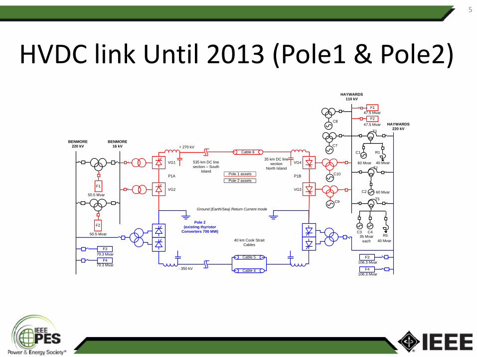
HVDC link Until 2013 (Pole1 & Pole2)
5
BENMORE220 kV
HAYWARDS220 kV
Cable 6
Cable 4
Pole 2 (existing thyristor
Converters 700 MW)
535 km DC line section – South
Island
35 km DC line section
North Island
40 km Cook Strait Cables
+ 270 kV
- 350 kV
Cable 5
HAYWARDS110 kV
C7BENMORE
16 kV
Ground (Earth/Sea) Return Current mode
F479.3 Mvar
79.3 Mvar
F3
F3
F4
106.3 Mvar
106.3 Mvar
C1
60 Mvar
T1
C4C335 Mvar
each
T5
C2 60 Mvar
T2
40 MvarR5
40 Mvar
R1
F2
50.5 Mvar
50.5 Mvar
F1
F247.5 Mvar
47.5 MvarC8
C9
C10Pole 1 assets
Pole 2 assets
VG3
VG4
P1B
VG2
VG1
P1A
F1

HVDC Pole 3 Project - Design 6
BENMORE220 kV
HAYWARDS220 kV
Pole 2 ( existing thyristorConverters 700 MW)
535 km DC line section – South
Island
40 km Cook Strait Cables
35 km DC line section
North Island40 km Cook Strait
Cables
+ 350 kV
- 350 kV
Pole 3(new thyristor
converters 700 MW)
HAYWARDS110 kV
C7
C8
C9
C10
BENMORE16 kV
F3
F4
79.3 Mvar
79.3 Mvar
Stages 1&2
Existing
Stage 3
F3
F4
106. 3 Mvar
106. 3 Mvar
C7-C1065 Mvar
each
Cable 6
Cable 4
Cable 5
Cable 7
4 0 Mvar
C1
60 Mvar
T1
C4C335 Mvar
each
T5
C2 60 Mvar
T2
R5
4 0 Mvar
R1
Reactive Power Supplyto Pole 3 at Haywards
Reactive Power Supplyto Pole 3 at Benmore
New 220kV Reactive Plant
Stages 1&2
New 220kV Reactive Plant
Stage 3
New 220kV Reactive Plant
And SVS Stages 1&2
New 220kV Reactive Plant
Stage 3
16 Mvar
16 MvarF8
F7

Seismic Design Aspect
• Both Converter Stations must have High Level of Seismic Resilience, particularly Haywards which is located only a few hundred meters from an active geological fault line
• Structural diversity between the new Pole 3 and the existing Pole 2 in an attempt to avoid common mode failures
• Seismic isolation of the converter building housing the thyristor valves, converter transformers and control / auxiliary system
•
7

Converter Building Seismic Isolation
8

Reactor & Bushing 9
• Reactor isolation • Shake table test

Design Coordination between Existing and New Plant
• Arrester arrangement including all existing arresters – V-I characteristics – Protective levels of the new surge arresters
• Existing Pole 1 DC filters, built identical to Pole 2 DC filters • Various components installed at the DC neutral bus need to
be replaced by components with higher rating
10

Reactive Power Control 11

AC Filters
• Overall filter design will ensure that the new AC filters do not cause undue loading of the existing filters during operation
• Wider AC frequency range (+/-2 Hz) • Triple-tuned AC filters TT11/13/24 have been
designed considering • 3rd harmonic filters (ST LO3) will be installed at
Benmore taking potential resonances of pre-existing low order harmonics into account
12

Stability, Modulation and Frequency Control*
• Supplementary Modulation Controls and Runbacks are implemented in the HVDC Control System – Weak AC grid – Increased power transfer capability
• DC current modulation to damp voltage swing • Frequency controls • Fast run backs • Round power mode *1400 MW New Zealand HVDC Upgrade: Introducing Power Modulation Controls and Round Power Mode Simon P. Teeuwsen, Geoffrey Love, Richard Sherry, Power and Energy Society General Meeting (PES), 2013 IEEE
13

Special Controls
Frequency Stabilization Control
14

Time Domain Simulation Results 15

Special Controls (Contd…)
Spinning Reserve Sharing
16

Time Domain Simulation Results 17

Special Controls (Contd…) Frequency Keeping Control
18
Constant Frequency Control

Round Power Mode 19
PDC
Pref
Bipole PowerPole 2 PowerPole 3 PowerPmin POLE = 35MW
Mon
opol
e Tr
ansi
tion
Leve
l
RP
Tra
nsiti
on L
evel
Pmin RP
Pmin RP
+Pm
in B
P
-Pm
in B
P
Mon
opol
e Tr
ansi
tion
Leve
l
Round Power Operation
Monopolar Operation P3
Bipolar Operation
Monopolar Operation P2
Bipolar Operation
RP
Tra
nsiti
on L
evel

Time Domain Simulation Results 20

Thank you
Siemens Energy Inc, USA
21
![H Controller Design for Robust Control in - · PDF fileController Design for Robust Control in MMC-HVDC System . ... (SVC) [2]–[3]. A VSC-HVDC system based on insulated-gate bipolar](https://img.dokumen.tips/doc/110x75/5ab81b377f8b9ad13d8c2d74/h-controller-design-for-robust-control-in-design-for-robust-control-in-mmc-hvdc.jpg)