Embed Size (px)
Citation preview

1
UpdatedTechnical Lessons Learned 100 Days After Quake, Tsunami at the Fukushima Dai-ichi, Units 1-6, Nuclear Power Plant
Akira T. Tokuhiro ([email protected]) Department of Mechanical Engineering, University of Idaho, 1776 Science Center Drive,
Idaho Falls, Idaho 83402 USA
Keywords: nuclear power plant, accident, meltdown, spent fuel pool, loss of off-site power, earthquake, tsunami
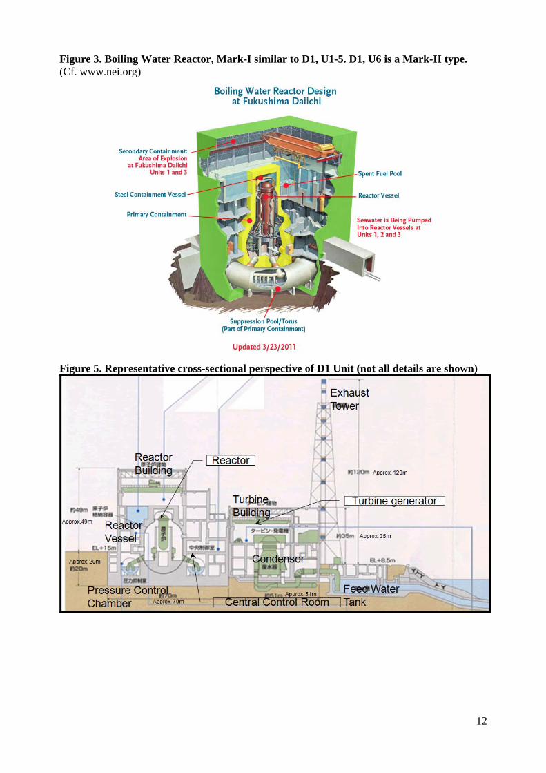
Post-Quake, Post-Tsunami State-of-Affairs and Lessons Learned (to date) The Japanese Fukushima Dai-ichi (D1) and Dai-ni (D2) nuclear power station with 4 GE-BWRs (4 x Mark I type) units (U1-4) at one site and 2 BWR units (U5-6; 1 each, Mark I, Mark II) respectively co-located side-by-side on the north-central eastern coast of Japan withstood a 9.0 earthquake and a large-scale tsunami on March 11, 2011. All six units were constructed via a GE/Hitachi/Toshiba collaboration from 1967-1979. Two planned GE ABWRs due to begin construction in 2012 have recently been cancelled. In spite of the immediate shut down of all units ( D1, U4 was shutdown at the time) based on ground-level acceleration and decay heat cooling for some 45 minutes, loss-of-offsite-power by ingress of water into the earthquake-proof diesel generators’ pit, initiated an event that can be broadly defined as loss-of-heat-sink, classified as a ‘beyond design basis accident’. Further, along with decay heat cooling of the reactor core, all units faced additional, unanticipated challenge of decay heat cooling of spent fuel pool (SFP) situated above the reactor core in proximity of both the core and containment building. In fact, for U1-4, the spent fuel pool is situated in a lightly-structured confinement building above the containment. During the initial week, March 11-18, there were up to three larger (likely H2 explosion) explosions, vapor/steam jets and fires that further stressed the RPV, the containment and (weather) confinement buildings. News releases based on TEPCO/NISA data analysis indicate consensus engineering opinion that the cores in Units 1, 2 and 3 partially to fully melted as a result of ill-timed response within the first 16-X hours. The extent of the core melt will not be known until access to the RPV is realized (see below on its anticipation). One of the later explosions conceivably damaged the primary (coolant) containment and thus, water found in the adjacent basement of the turbine building pointed to high-levels of radiation including fission products. Additional large volumes of contaminated water were found in the U-shaped electrical conduit ‘trenches’ off of U1-3 and spreading into other areas such as beneath the reactor site. Technical specifications for U1-6, focused on relevant parameters at the time of (accident) initiation, are given in Table 1. Note that the Table includes details about the lateral acceleration threshold for shutdown and also the number of fuel assemblies in the SFP that contributed to the accident. The common SFP is also included. Table 2 gives estimates of the reactor core decay heat versus time after shutdown; thermal decay heat determines the cooling needed after shutdown. For U3 and U4, we are approaching ~1MW and 5MW respectively in decay heat magnitude. A little known site map is given in Figure 1, along with ‘before’ and ‘after (March 18)’ images in Figure 2. The site map is particularly handy in conjunction with images by Cryptome (2011), both in terms of location of key (liquid) storage tanks, the reactor building (RB), turbine building (TB) and access points. Figures 3 and 4 respectively provide qualitative schematics of the Mark I plant with unique toroidal suppression pool and location of the SFP, and a sectional view, with several overall relevant vertical dimensions. We present as self-evident that as a result of addition of water (fresh, seawater), water not contained in volumes flow into lower elevations. Notable in Figure 4 is the realization that there are flow paths of contaminated water from the containment into the basement of the turbine building and further

2
into channels (trenches) beyond where it can leak into the hydrosphere (ocean or water source). These are presented here to facilitate your own assessment of the timelines and news releases since March 11, 2011. Regularly issued press releases include the following: MEXT, JAIF, IAEA, NRC, TEPCO, Kyodo News Wire, The Japan Times, Wikipedia and Der Spiegel (all since March 11, 2011). The most viewed Internet-based news included (all Japanese): NHK-BS2, Fuji News Network, Tokyo Broadcasting System, Nikkei and Asahi News Network. Since event initiation the above news sources have reported a number of (likely) hydrogen explosions, venting of radioactive steam plumes, and fires. Figure 5 provides a timeline of events up to the end of March 2011 with additional information on radiation exposure units, its health impact, exposures due to specific activities and notable past nuclear events such as Chernobyl and TMI. Interestingly enough, the reported events leading to global radiation fears may have substantiated the author’s work [Tokuhiro, 2001]; that is, that mass-media dissemination of ‘nuclear’ and ‘radiation’ events accentuates perception of risk by a factor of at least 1000-times. In this article, Tokuhiro first presented time (T)- and number (N)-scale eigenmentrics. The author also contends {Tokuhiro, 2011] that multifold, (seemingly) complex issues can be meaningfully discussed by adopting five key ‘eigenmetric’ scales as follows: 1) time, 2) length (L), 3) energy (E), 4) distribution (D) and 5) number. Two additional ‘social’ metrics are as follows: 6) information (I) and 7) people/persons (W- ‘who’ conveyed the ‘information’(I) to ‘whom’). We demonstrate the utility of the eigenmetrics per example below by noting these metrics. • TEPCO has reported (W, I )that more than 100,000 tons (N,L)) of contaminated (E) water has leaked (D) from the damaged Fukushima Daiichi reactors (D). Given concerns over the spreading of contamination (E, D) during the rainy season (T), the company is focused on storage and filtering(D, L, E). TEPCO plans to start using equipment that can filter 1,200 tons (N) of water a day (T) in mid-June (T). In mid-August (T), the company plans to install an underground storage tank (D) that can hold 100,000 tons(L) of water. TEPCO is measuring the level of radiation (E) in groundwater (D) near the plant to check for possible wastewater leakage. TEPCO reportedly has plans to stop all leaks (D) of highly contaminated water from the site this month(T). We simply note that ‘D’ answers ‘where’, while ‘L’ per ‘L x L x L’ represents volume. We take radioactive decay as emission of energy, ‘E’, that can do harm. The number scale is typically a quantity that can be measured such as mass, weight or cost. Returning to the events that have been reported over the last 100+ days, under emergency response and (technical) crisis management, the world has witnessed helicopter drops of water, pumping of seawater into the containment building, spray injection cooling of the SFP using a ~15m(50 foot) ‘arm’ affixed to a large truck and recent pumping of ‘clean’ water brought to the site via a large barge-based tank. Since mid-May we are witnessing the recovery, restoration and cleanup effort via installation of improvised engineered systems (heat exchangers, inert gas injection) in order to first reach a ‘cold-shutdown’ condition and second, to assess the extent of damage/hazard in order to begin planning the cleanup effort. Global mass-media continues to report the events non-stop, week-after-week. As a result of the recovery effort, large volumes of contaminated (radioactivity-laden) water have collected in various channels and basins and in early April were released into the ocean. Limitation on storable liquid effluents remains a crisis management challenge. Detectable concentrations of radioactivity have been measured in farm and sea products, such as green vegetables, beef and fish, within the 20km and 30km evacuation zones. Potable water was also contaminated to varying degrees. Through all this, TEPCO, NISA and the Japanese government have been the ‘face’ of the daily reporting of the situation. It was some 60+ days after March 11th that a joint press conference was convened; separate press
3
releases have been a source of conflicting information and perspectives. It is evident that, as the situation persists, the public perception of risk and benefit of nuclear energy is shifting toward the former; that is, an anti-nuclear perspective not only in Japan but other nuclear nations. From a technical perspective, up to the end of June 2011, I believe that the global community of nuclear energy professionals may acknowledge the provisional list of lessons learned. The initial list published in May 2011 in Nuclear Exchange [Tokuhiro, 2011 ] was based on professional judgment and mass-media reports up to end of the first week, April 2011. This update includes further information up to the end of June. It includes an extrapolation based on the recent IAEA fact-finding preliminary summary [IAEA, 2011], the UK ONR’s national report [UK, 2011] and others. At this point, it is clear that full technical assessment of the extent of in-core, in-vessel, in-containment damage will not be forthcoming for at least 5-years. Post-TMI images of the partially melted core became available in 1985, 6 years after the accident (Wikipedia). Cleanup was completed in 1990. So, with multiple units with partial core and/or SFP damage, we can only project that assessment may be in 2016 (5-years) and cleanup sometime between years, 2017-2027. As for the potential impact on the global nuclear energy renaissance, it seems self-evident that there will be a 1-3 year ‘slowdown’; however, anything beyond this is highly speculative. The reported phase-out of nuclear power in Germany is defined in terms of a 2022 target. So, as reported previously, permit me to again list some of the lessons learned to date. These are classified broadly into two general categories, “Design” and “Operational”, with second classifier that is more specific as noted. The IAEA’s report largely contains ‘operational’ findings (9 of 11 noted). In contrast, this work identifies a balance of 12 ‘design’ and 11 ‘operational’ lessons learned to date. Operational is also understood as part of an implementation of ‘institutional’ philosophy. New and update lessons are noted via (new) and (updated) designations; otherwise, they originally appeared in early May 2011. Additionally, we identify the key eigenmetrics (T,L,E,D,N) and where applicable, (I,W), in order to facilitate further discussion. Tlessons are:
1) Design/R&D. Nuclear R&D institutions must consider alternatives to zirconium-based and zircaloy cladding (T, N) so that the chemical reaction (E, D) that generates hydrogen is prevented. Hydrogen explosion (E) exacerbates accident management. We (as an industry) need to accelerate development and deployment of non-hydrogen producing cladding materials; that is, assuming that the coolant/moderator/reflector remains (light) water. For GCR, water ingress may initiate a reaction with graphite to generate CO2 and H2(T, D, E) Related to IAEA’s ‘(10)’
2) Design/R&D. Nuclear R&D institutions must consider degradation dynamics (T,L,E,D,N) of cladded fuel and fuel assemblies in-core and in spent fuel pools. We need a better understanding of the potential fuel ‘reconfiguration’ (D) under, zircaloy-water chemical reaction (E) such that the cladding is lost and further (L,D,E), the fuel begins to melt. Unless the reconfigured core or SFP is known (D), one cannot adequately know the availability of coolant flow paths (T,L,E,D,N) other than the fact that the entire spent fuel mass is submerged in coolant. Our predictive capability of partially (5% to 95%) melted or degraded core (or SFP) configuration (D) is inadequate.
3) Design. It is clear that the spent fuel pool (SFP) cannot be in proximity of the reactor core (D), reactor pressure vessel or containment itself. The SFP, in its current form, is essentially an open volume subcritical assembly (N) that is not subject to design requirements generally defining a reactor core. Yet, unless thermohydraulic cooling (E) is maintained, it is subject to similar consequences as a reactor core without adequate cooling. Therefore, we need new passive designs of the SFP (L,D,E), away from the actual plant’s reactor core.

4
4) Design. (Thus) New standard and design requirements are needed for the SFP. This is especially true for NPPs located in earthquake zones (L). The SFP should be ‘reclassified’ as a subcritical assembly (L,D) with potential for criticality (E) with no active/passive control (rod or soluble ‘poison’) mechanism. This warrants engineered design of immersed, co-located control rod elements, including DBA and BDBA analyses (T,L,E,D,N). In addition, in order to prevent loss-of-coolant (T,L,E,D,N), the SFP should have a condensate ‘cover’ in order to minimize loss-of-coolant due to sloshing of the free surface. Lastly, the SFP should be some distance (L) from the reactor plant.
5) Design. In future designs of nuclear reactor systems, we need to reconsider core configurations with low aspect ratio rather than high aspect ratio. Under decay heat natural circulation cooling (single-phase or under boiling), one may need to minimize the coolant volume inventory that is needed to maintain the core submerged in liquid coolant. This further identifies a need to select a coolant that is on-hand; that is, an intended coolant if it is a LWR and a secondary coolant that may suffice for decay heat cooling. This obviously opens up a fundamental question on fluids/materials selection to serve as coolant, moderator and reflector in a nuclear reactor system. The overall maximum vertical height should be limited by the height of emergency responder cooling equipment such as a crane-based fire hose or similar. In other words, it is not wise to build a structure so tall that firefighting equipment cannot adequate inject water or similar liquid coolant.
6) Design/Site Design Basis. Having multiple (reactor) units at one site needs critical review in terms of post-accident response and management. We must consider the energetic events at one unit exacerbating the situation (safe shutdown) at the other. For nuclear installations, we should review the co-location of facilities with a potential for a criticality accident in one exacerbating access to another during first response. Access is obviously needed for ‘cold shutdown’ of the intact unit, relative to the damaged unit, in a timely manner.
7) Design/Site Design Basis. There is a need for standby back-up power, via diesel generator and also battery power, at a minimal elevation (100feet/31m) above and remotely located. This is needed to offset loss of off-site power for plants subject to environmental water ingress (foremost tsunami). Spare battery power should also be kept off-site and in a confirmed ‘charged’ state. There is also a critical need for standby back-up cooling capability (gas or liquid); that is, a liquid-to-air or liquid-to-liquid heat exchanger that can be installed in a timely manner if/when the primary/secondary cooling circuits are unavailable.
8) Design/Site Design Basis. For nuclear power plants located in or near earthquake zones, we cannot expect structural volumes and ‘channels’ to maintain structural integrity. We should also expect the immediate ground underneath these structures to be porous. It may ‘liquify’ under earthquake and thus become a path for contaminants. Thus design of these volumes and channels should be such that they minimize connections to other (adjacent) volumes from which contaminated (liquid) effluents can flow.
9) Design/Site Design Basis. Place larger structures of hydrodynamic design toward the ocean and smaller installations in the ‘wake’ region behind these larger structures. That is, in the case of Fukushima, the tsunami always approaches from the ocean. It thus makes imminent sense to hydrodynamically design these larger structures with smaller structures in the wake region of the larger structures. Structures in the wake region will likely have a higher probability of sustaining less damage if place directly on ‘ocean-side’.
10) Design/Reactor Design Basis. Loss-of-offsite-power and only partial availability of diesel generator-based and/or battery-based backup power needs to be analyzed as DBA or BDBA.
11) Design/(Gas-Cooled) Reactor Design Basis. For loss-of-offsite-power and only partial availability of generator-based and/or battery-based backup power, any depressurization

5
DBA or BDBA may require timely injection of additional coolant (gas), assuming that water is not an option.
12) (New) Design/Reactor Design Basis. Although analytical methods and means are available for DBA or BDBA, the industry lacks means to assess the system ‘resiliency’ especially under BDBA. (Cf. Woody Epstein)
13) Operational. If an ‘in-containment’ SFP is maintained, then the fuel transfer crane system must be designed so that it is available to remove the fuel during a post-accident phase or a second means such as a robotic arm needs to be available.
14) Operational. We need to identify or review key valves for emergency core cooling and review requirements that they are non-electrically ‘functional’. That is, these valves need a secondary means of open and closed status that is remotely located.
15) Operational. Further, there is a definite need for a backup (shielded) reactor plant and/or ‘criticality possible installation’ control center that is offsite (remote) so that the accidents can be managed with partial to full extent of reactor plant or criticality possible installation status (P, T, flowrates, valve status, tank fluid levels, radiation levels). Sensor will need to be ‘hardened’ to withstand energetic events.
16) Operational. There needs to be a volumetric guidance analysis for ultimate (decay heat) cooling contingency plans so that not only limitations on volume are understood but also transfer of liquids from one volume to another. Spare tanks and water-filled tanks need to be kept on site as uptake tanks for ‘runoff’ in case of addition of coolant during accident management phases. Additional means to produce boric acid need to be available off-site. Earthquake-proof diesel generator housing also needs to be water-proof. Remote diesel generators are also needed with access to equally remote diesel fuel tanks (also see6).
17) Operational. Under emergency and crisis management, wider access roads are needed to and from NPPs. The access roads need to be clear of debris and of such width to accommodate large-scale trucks needed as first response and during the recovery phase. A way to access the plant via water calls for infrastructure (boats, water-containing barges, jet-skis etc) and is needed as part of a contingency plan for those plants located near bodies of water.
18) Operational/Standardization. Color-coded major components so that in case of an accident such as that at Fukushima NPP station, we will be able to quickly identify the major components from digital images. Nuclear plant site maps, such as Figure 1, should be ‘downloadable’ or available upon request in order to be used in accident management.
19) Operational/International. An international alliance of nuclear reactor accident first responders and beyond first response, a crisis management team is needed. No such international alliance is available at this time. The global nuclear industry cannot wait 3 weeks for international participation.
20) Operational/International. We should consider and work toward an international agreement on standards for regulated levels of radiation activity and exposure to the general public and separately, to those workers responding under emergency and extended ‘recovery’ phases. We should also be consistent in definition and practice of implementing evacuation zoning. We should also strongly encourage acceptance and use of SI units for radiation activity and exposure (consisting use of μSv/hr or mSv/hr). (new) In fact, when strictly expressed, the above should be an uniformly accepted standard by leading nuclear energy nations.
21) (New) Operation/International. Voluntary participation in national/international vendor or reactor type specific working group, although facilitates exchange of information and post-construction upgrades, are often non-binding in terms of implementation of new (safety) developments and may not be directly linked to a nation’s regulatory authority. The international regulatory body also does not have the authority to require implementation of developments in any particular member state; thus, makes retrofitting/upgrades of safety features and/or safety-relevant developments ineffective.

6
22) (New) Operational/International. In the event of a nuclear power plant accident with release of radiation, host nation should (must) have an immediate-to-longer term and statistically significant radiation protection and health monitoring program ready to implement.
23) (New) Operational/National. In a given nation, a market- and post-accident driven commercial nuclear energy infrastructure can impact the public confidence in nuclear energy itself. That is, there (seems to be) is a need to replace aging, previous generation nuclear plants with newer plants in a timely manner so that public confidence nuclear energy is maintained.
24) Operational/International. In order to promote and actively practice a true “Global Nuclear Energy Partnership (GNEP)”, I hereby propose that we designate the Fukushima NPP site and its reactors as an international nuclear post-accident management and decommissioning center (INPMD). The INPMD should be sanctioned by the Japanese government and led by a new Japan-based commission with international lead members ( example, IAEA, U.S., France, Korea, China). The commission should however establish a consortium of member nations. The official language should be English. The level of participation should correspond to commitment of equipment and experts. The lessons learned and data generated in the recovery phases should be open to all. Each consortium member nations should also have risk communication representatives.
Appendix Extracted below are the list of findings and lessons learned from the ‘IAEA International Fact Finding Expert Mission of the Nuclear Accident Following the Great East Japan Earthquake and Tsunamis, Preliminary Summary’(IAEA, 2011). The number in parenthesis and the ‘design or operational’ classification has been added to facilitate discussion in this paper. • (1; Operational) The Japanese Government, nuclear regulators and operators have been extremely open in sharing information and answering the many questions of the mission to assist the world in learning lessons to improve nuclear safety.
• (2; Operational) The response on the site by dedicated, determined and expert staff, under extremely arduous conditions has been exemplary and resulted in the best approach to securing safety given the exceptional circumstances. This has been greatly assisted by highly professional back-up support, especially the arrangements at J-Village to secure the protection of workers going on sites.
• (3; Operational) The Japanese Government’s longer term response to protect the public, including evacuation, has been impressive and extremely well organized. A suitable and timely follow-up program on public and worker exposures and health monitoring would be beneficial.
• (4; Operational) Planned road-map for recovery of the stricken reactors is important and acknowledged. It will need modification as new circumstances are uncovered and may be assisted by international co-operation. It should be seen as part of a wider plan that could result in remediation of the areas off site affected by radioactive releases to allow people evacuated to resume their normal lives. Thus demonstrating to the world what can be achieved in responding to such extreme nuclear events.
• (5; Design) Tsunami hazard for several sites was underestimated. Nuclear designers and operators should appropriately evaluate and provide protection against the risks of all natural hazards, and should periodically update these assessments and assessment methodologies in light of new information, experience and understanding.
7
• (6; Design) Defense in depth, physical separation, diversity and redundancy requirements should be applied for extreme external events, particularly those with common mode implications such as extreme floods.
• (7; Operational) Nuclear regulatory systems should address extreme external events adequately, including their periodic review, and should ensure that regulatory independence and clarity of roles are preserved in all circumstances in line with IAEA Safety Standards.
• (8; Operational) Severe long term combinations of external events should be adequately covered in design, operations, resourcing and emergency arrangements.
• (9: Design, Operational) The Japanese accident demonstrates the value of hardened on-site Emergency Response Centers with adequate provisions for communications, essential plant parameters, control and resources. They should be provided for all major nuclear facilities with severe accident potential. Additionally, simple effective robust equipment should be available to restore essential safety functions in a timely way for severe accident conditions.
• (10; Design) Hydrogen risks should be subject to detailed evaluation and necessary mitigation systems provided.
• (11; Operational) Emergency arrangements, especially for the early phases, should be designed to be robust in responding to severe accidents.
References Asahi Network at http://www.tv-asahi.co.jp/ann/ Cryptome.org at http://cryptome.org/eyeball/daiichi-npp/daiichi-photos.htm Der Spiegel Online at http://www.spiegel.de/thema/fukushima/ Fuji Network at http://www.so-net.ne.jp/streaming/ International Atomic Energy Agency at http://www.iaea.org/newscenter/news/tsunamiupdate01.html IAEA, IAEA International Fact Finding Expert Mission of the Nuclear Accident Following the Great East Japan Earthquake and Tsunamis, Preliminary Summary, 1 June 2011 (Japan) Ministry of Education, Culture, Sports, Science and Technology at http://www.mext.go.jp/english/radioactivity_level/detail/1303986.htm Japan Atomic Industrial Forum at http://www.jaif.or.jp/english/ Japan Times at www.japantimes.com Kyodo News Wire at english.kyodonews.jp/news/japan_nuclear_crisis/ NHK-BS2 at http://wwitv.com/tv_channels/b04626.htm Nikkei at http://www.nikkei.com/video/ Squid TV News. http://watch.squidtv.net/asia/japan.html. The following videostream news outlets, mostly in Japanese: Fuji News Network, Tokuhiro, A., A comparison of safety culture associated with three engineered systems in Japan and the United States, JSME International Journal, C, June 2001 (No. 99-4098) Tokuhiro, A., A Perspective of the post-Fukushima Safety Culture Defined in terms of Level of Acceptance of Risk Versus Benefit, Associated with Hazard-Inherent Engineered Systems, under preparation, 2011.Tokuhiro, A., Initial Technical Lessons Learned following the Post-Quake, Post-Tsunami, Fukushima Dai-ichi, Units 1-6, Nuclear Power Plant, Nuclear Exchange, May 2011. Tokyo Broadcasting Company at http://news.tbs.co.jp/ Tokyo Electric Power Company at http://www.tepco.co.jp/en/press/corp-com/release/11032503-e.html World Wide Internet Television, Japan at http://wwitv.com/television/106.htm

8
World Nuclear News, “Prepare for a new nuclear industry”, Apr 6, 2011, at http://www.world-nuclear-news.org/NP_Prepare_for_a_new_nuclear_industry_0604111.html?utm_source=World+Nuclear+News&utm_campaign=a5a84652f5-WNN_Daily_7_April_20114_7_2011&utm_medium=email Wikipedia at www.wikipedia.org for the following entries: Fukushima I Nuclear Power Plant, Fukushima II Nuclear Power Plant, Tokyo Electric Power Company; all since March 11, 2011

9
Table 1. Summary of Fukushima NPP unit selected specifications
Table 2. Thermal power output of reactor core fuel after shutdown for selected times.
Reactor Type BWR-3 BWR-4 Thermal (MW) 1380(100%FP) 2381(100%FP)
Power After Shutdown Time (seconds) Time (s,m,h,d,y) MW (thermal) % FP MW (thermal)
1.00E-01 0.1s 139.33 10.0961 240.39 1.00E+00 1s 86.86 6.2943 149.87 1.00E+01 10s 53.76 3.8956 92.75 1.00E+02 100s 32.87 2.3820 56.72 1.00E+03 16.7m 19.69 1.4271 33.98 1.00E+04 2.8h 11.38 0.8245 19.63 1.00E+05 28h 6.13 0.4445 10.58 1.00E+06 11.6d 2.84 0.2057 4.90 1.00E+07 116d 0.89 0.0641 1.53 1.00E+08 3.2y 0.12 0.0087 0.21 1.00E+09 31.7y 0.01 0.0006 0.02

10
Figure 4. Fukushima nuclear power station site map (original in Japanese)
LEGEND: The buildings below are marked but NOT NUMBERED but on diagram T/B = turbine building; R/B = reactor building RWB = reactor waste building; CB = control room building U1, U2, U3, U4, U5, U6 correspond to Units 1‐6 SCALE is approximately as follows: 500m = 1.843inches 1) Turbine building, ventilation system stack 2) Incinerator building (AT‐I think for materials that can be burned) 3) (contaminated/radioactive) Waste transfer (removal) vessel ‘inlet/outlet’ building 4) (contaminated/radioactive) Waste collection (concentration) processing (disposal) building 5) Water outlet for U1‐4 6) Site bunker building 7) Suppression pool water surge (tank) 8) coarse solid (contaminated/radioactive) waste processing building 9) (operations assist, common) facility building. (likely the subcontractors engineering building) 10) (contaminated/radioactive) waste X building 11) (AT ‐ for U3, 4) ultra high tension ‘open/close place’ (AT‐likely the busbar for high voltage). Same as 16
12) Exhaust stack 13) activated noble gas holdup equipment building 14) Fukushima nuclear power technical training center 15) Service hall ( visitor’s center) 16) (for U1,2) ultra high tension ‘open/close place’ (switching station for high voltage). Same as 11 17) weather monitoring station/instrumentation) 18) Settling (precipitation) basin 19) Exhaust stack 20) Filtration water tank 21) Solid waste storage 22) Business office building 23) ‘improvement’ construction office place 24) Solid waste storage 25) (AT‐sea) water intake 26) Pure water tank 27) Water processing room
11
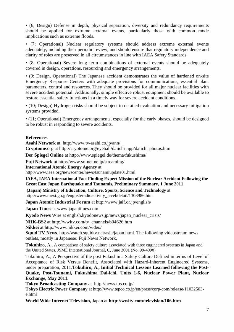
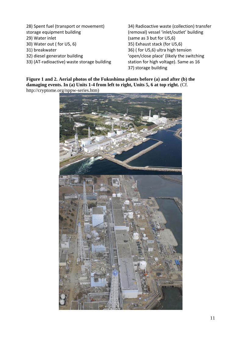
28) Spent fuel (transport or movement) storage equipment building 29) Water inlet 30) Water out ( for U5, 6) 31) breakwater 32) diesel generator building 33) (AT‐radioactive) waste storage building
34) Radioactive waste (collection) transfer (removal) vessel ‘inlet/outlet’ building (same as 3 but for U5,6) 35) Exhaust stack (for U5,6) 36) ( for U5,6) ultra high tension ‘open/close place’ (likely the switching station for high voltage). Same as 16 37) storage building
Figure 1 and 2. Aerial photos of the Fukushima plants before (a) and after (b) the damaging events. In (a) Units 1-4 from left to right, Units 5, 6 at top right. (Cf. http://cryptome.org/nppw-series.htm)
12
Figure 3. Boiling Water Reactor, Mark-I similar to D1, U1-5. D1, U6 is a Mark-II type. (Cf. www.nei.org)
Figure 5. Representative cross-sectional perspective of D1 Unit (not all details are shown)