Embed Size (px)
Citation preview
Ready Made RC, LLC
Assembly Instructions for:
Updated 9/22/14
RMRC Anaconda

Thank you for purchasing the RMRC Anaconda! It is important to read the manual in its
entirety before your maiden flight. This model is not intended for new or beginner pilots. It
requires a large, smooth takeoff/landing area and does not have self-correcting tendencies that
most new pilots require. Please obey all current laws and use common sense for safety when
operating.
Ready Made RC Support: If you have any issues with your aircraft or questions, please direct
them to our support system located at www.readymaderc.com/support and we would love to
help you out!
Note: We reserve the right to modify information presented and cannot be held liable for errors
within.
Table of Contents:
Parts list for KIT: 3-7
Parts list for PNP: 8
Fuselage Assembly: 9-16
Wing Assembly: 17-22
Tail Assembly: 22-27
Final Assembly for KIT and PNP: 28-31
Setup Tips: 31-32 Required to operate:
Motor – 3520 750-950KV*
Propeller – 13-15”
ESC – 80A*
Servos o 2x (Ailerons)* o 2x (Elevator/Rudder)*
2x (Flaps – Optional)Batteries – 4s 8,000-20,000 mAH *Included in PNP
Required for build:
Epoxy or personal choice of glue
Phillips screw drivers
1.5 and 3mm hex tools
Hobby Knife
Masking or Painter’s tape
Servo Centering Tool
Blue Thread Locker

Kit Package Contents:
Foam parts (A)
1. Main Wing Set
2. Ruddervators
3. Front Boom Covers (Under Main Wings)
4. Rear Boom Covers (2 halves each)
5. Mid Boom Covers
6. Motor Nacelle
7. Canopy
8. Removable Camera Pod
9. Fuselage Halves

Carbon Fiber (B)
1. 480mm x 8mm (2 pieces)
2. 1000mm x 12mm
3. 870mm x 6mm
4. 740mm x 13.5 mm (2 pieces) Notice stopper screws
5. 870mm x 16mm (2 Pieces)

Plastic parts (C)
1. Front Boom Anchors (Notice that 2 have retainer for female stereo jack)
2. Rear Boom Anchors
3. Control Horns (May be push through style)
4. Bolt Bushings for Main Wing
5. Nut Anchors for Ruddervator Joiner
6. Nose Gear and Steering Servo Anchor
Notice: Some of the plastic pieces may be a different color than shown in manual (Black/White)

Wood Parts (D)
1. Adjustable Battery Tray
2. Motor Mount (Choose according to motor size) 44mm vs 50mm X pattern
3. Wing/Fuselage Anchors
4. Rear Landing Gear Anchors (2 pieces, one is not pictured)
5. Camera Bay Hooks
6. Camera Bay Anchor
7. GoPro camera retainer

Hardware (E)
1. Rear Landing Gear
2. Rear Wheels
3. Front Wheel
4. Canopy Magnets
5. Nose Landing Gear
6. Linkage Stoppers
7. T-Nuts, Bolts, Nylon Lock Nuts
8. Wing Bolts with Washers
9. Ruddervator Joiner
10. Control Rods
11. Servo Leads
12. Velcro Battery Strap (May be different in color)

PNP Parts Included:
Fuselage
Right and Left Wings
Right and Left Ruddervators
Tail Booms
Decal Sheets (2)
Wing Spars Front and Rear
Tail Boom Covers Right and Left
Motor Nacelle
Rear Landing Gear
Hardware Package (Found inside fuselage)

Fuselage Assembly
1. Locate wood motor mount plates (2D) and place the X bracket from your motor
onto it. Once you have chosen the correct size for your motor, you may set the
other aside.
2. Insert T-Nuts into wood pieces and secure with epoxy. Leave one of the rear
landing gear plates with no T-Nuts installed. (4E)
a. Be sure to note correct T-Nut sizes for appropriate bolts!
b. M3 for motor mount, M4 for wing and landing gear anchors
3. Place wing bolts into Wing Anchors to assist with fuselage gluing.
a. Note correct bolt direction. Bolts should not be able to pull out T-Nut
under pressure.
b. Note where Anchors fit into the inside grooves of the fuselage
4. Apply glue to the following places:
a. All mating surfaces of Fuselage (One half)
b. All mating surfaces of Wing Anchors
c. All mating surfaces of Motor Mount

Note that wing bolts are used to help align wooden anchors during gluing process:
5. Carefully press opposite half of fuselage together and secure with tape.
a. Make sure wing anchors and motor mount are still securely in place

6. Locate Nose Gear and Steering Servo Anchor (6C) and use epoxy to secure in
nose of fuselage. Try to avoid excess epoxy from blocking servo path.
7. Locate rear landing gear anchors (4D). One should have T-Nuts glued in place
and one should not.
a. Epoxy plate without T-Nuts into allotted area on the bottom of fuselage
b. Use holes as a guide to press Phillips driver straight through foam (or
appropriate drill). These holes could not be moulded at the factory.
c. Use wood anchor with T-Nuts installed and reach inside to bolt landing
gear to bottom of fuselage.

8. Locate Nose Gear (5E) and white control horn.
a. Install linkage stopper as shown
b. Tighten control horn with 1.5mm tool onto flat spot of nose gear.
c. Push nose gear through forward hole in plastic anchor
d. Use collet and 1.5mm tool to secure.
9. Insert steering servo into plastic housing.
a. Install control rod as shown
b. Center servo and install control horn
c. Use 1.5mm tool to secure control rod
d. Adjust control rod to center wheel if needed

10. Locate and Install wheels on front and rear landing gear. (2E & 3E)
a. Use appropriate collet and 1.5 tool to secure
11. Locate Canopy (7A) and Magnets (4E)
a. Trim excess foam flashing from canopy with hobby knife
b. Test fit that canopy will close properly
c. Epoxy magnets into fuselage
d. Use painter’s tape to cover magnets and place the extra magnets on top
i. This will create a barrier to avoid a stuck canopy
e. Apply epoxy to magnet bay inside of the canopy
f. Tape and allow to cure

12. Locate wood camera bay anchor (6D)
a. Epoxy T-Nuts into place as shown.
i. M3 for gimbal mount
ii. M4 for center
b. Glue plate under fuselage as shown.
i. Be careful not to have excess glue where wood hooks will travel.

13. Locate Camera Bay (8A) and Wood Bay Hooks (5D)
a. Glue hooks into allotted space in the camera pod. This will allow the pod
to lock into the bay anchor in the fuselage.
b. Repeat steps used to glue magnets in canopy for camera bay.
14. Locate GoPro retainer (7D)
a. Glue wood pieces as shown. This piece will lock the GoPro in place during
flight in camera pod.

15. Locate Battery Tray (1D) and Battery Strap (12E)
a. Loop Battery strap into rear or center slots in battery tray.
b. Slide battery tray into grooves in forward fuselage.
c. Secure with M4 Bolt and washer. This is adjustable for center of gravity.
16. Install motor with M3 bolts (E7) and ESC into fuselage
a. Use Hook and Loop tape to attach ESC to fuselage.
b. Use blue thread locker on motors screws.

Wing Assembly
1. Locate Forward Boom Anchors (1C) and Wing Spars (1B & 4B)
a. Remove spar covers in wing and dry fit boom anchors.
i. Note that female servo jacks must be towards leading edge of wing and
tail booms must pass through.
ii. Check anchors for excess plastic that would keep them from clamping
down and trim if necessary
iii. Note screw placed in main wing spar must be positioned towards outside
of wing to allow for inner spar (2B).
2. Cut rear spar cover to fit over rear anchor as shown: Center discarded
a. Check for proper spar and spar cover fitment.
b. Glue all mating surfaces.
c. Make sure that spars are fully inserted before allowing to cure.

3. Locate 4x M3x15 bolts and 4x locking nuts and insert them as shown.
a. Do not compress the clap at this time.
b. Apply glue to nuts to prevent them from backing out when pod cover is installed.
4. Locate and center aileron servos.
a. Glue servos into wing and fasten horns as shown at 90*.
i. Some servos may require some additional foam trimming.
b. Cut out additional foam at both ends of the ailerons.
i. Make sure that aileron can flex freely without interference.
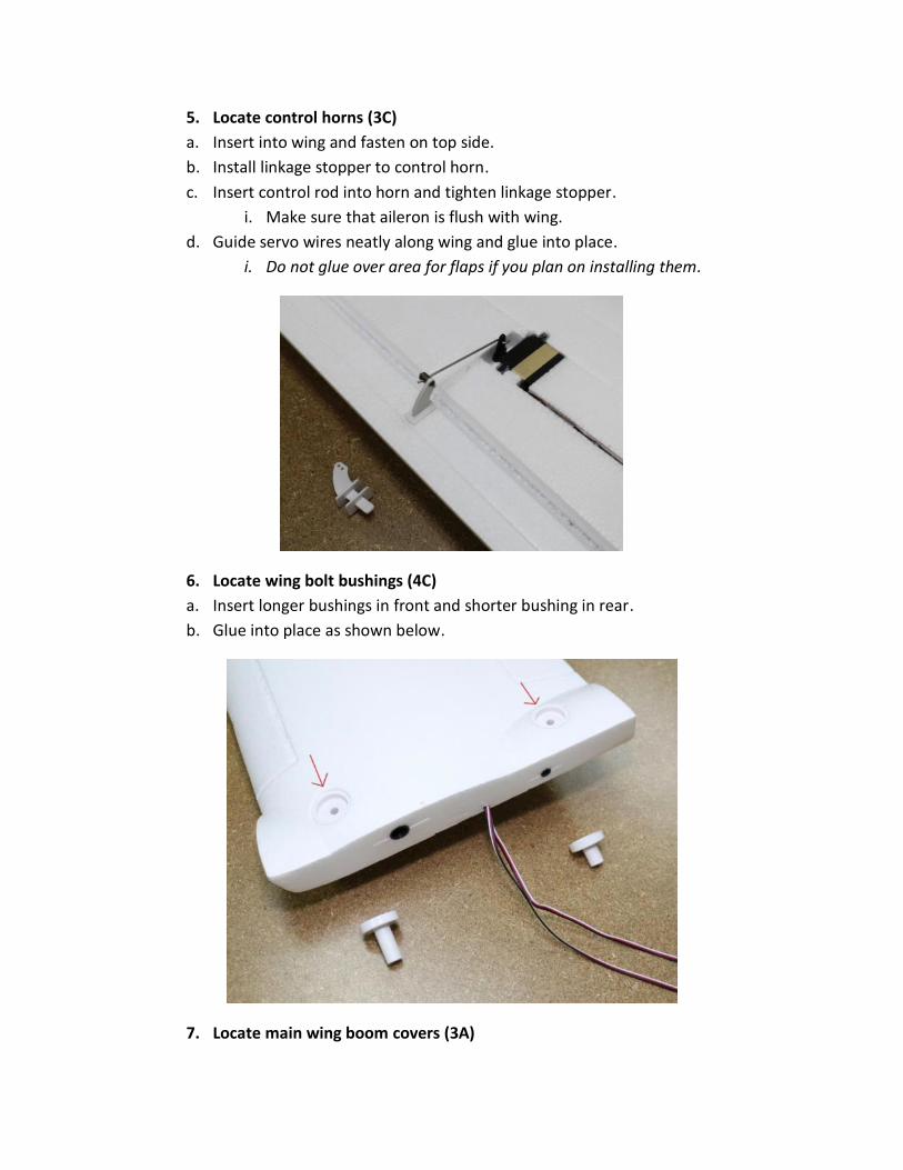
5. Locate control horns (3C)
a. Insert into wing and fasten on top side.
b. Install linkage stopper to control horn.
c. Insert control rod into horn and tighten linkage stopper.
i. Make sure that aileron is flush with wing.
d. Guide servo wires neatly along wing and glue into place.
i. Do not glue over area for flaps if you plan on installing them.
6. Locate wing bolt bushings (4C)
a. Insert longer bushings in front and shorter bushing in rear.
b. Glue into place as shown below.
7. Locate main wing boom covers (3A)

Update 9/22/14 – We now recommend installing the boom covers after final assembly. This
allows you to make sure the stereo jacks have fully seated. You should not need to see this
again after the first time and you are free to glue or use supplied tape as you wish.
a. Note that there are two sides and they are not interchangeable.
b. Make sure again that the nuts are seated and glued into retainers.
c. Once you have the correct side, glue into place.
8. Flap Installation (Optional)
a. Cut out triangle shaped foam supports in both leading and trailing edge.
i. Caution – Do not cut through hinge when removing supports.
b. Cut out additional foam at both ends of flaps and ensure free movement.
c. Install servo horns into flaps as shown. Leading edge will require glue.

d. Install linage stoppers into control horns.
e. Glue flap servos into position and setup linkage as shown.
i. To achieve full travel, the servo must be off-center at zero position.
Flaps at zero position:

Flaps at full position:
f. Route servo wires neatly into channel and glue into place.
Tail Assembly
1. Locate pieces 2A, 4A, 2C, 5C, 9E as shown below:

a. Dry fit foam stabilizers onto boom anchors and place onto corresponding
ruddervator to ensure proper fitment.
b. Trimming of the boom anchor clamps may be required for proper operation.
c. Insert M3 bolts into housing and secure with lock nut.
i. Glue lock nut into housing to avoid frustration in the future.
ii. Do not fully tighten clamp at this time.

d. Glue boom anchors onto ruddervators as shown below:
2. Locate and center ruddervator servos.
a. Install servo horn and glue servo into position.
i. Some trimming of the foam may be required depending on servo used.
b. Install control rod stopper onto control horn.
c. Install control horn into control surfaces.
d. Insert rod into servo horn and tighten rod stopper as shown below:

3. Glue inner boom anchor cover (4A) onto anchor and ruddervator as shown.
a. Note: glue servo wire along channel (green line)
b. Glue outer boom cover onto anchor and ruddervator as shown.
i. Note: avoid applying glue to bolts.
ii. Be sure that you do not leave excess glue where boom will pass.

4. Locate bracket 9E, 4x M3 bolt/nuts from E7, and square anchors from C5.
a. Glue anchors into ruddervators as shown.
b. Attach bracket to one ruddervator and tighten bolts.
c. Attach opposite ruddervator and tighten bolts.
5. Tail booms – Locate foam boom covers (A5) and CF booms (B5)
a. Dry fit foam covers to ensure proper fit
b. Apply glue to sections shown in green.
i. Avoid allowing glue to seep into spar channel

c. Tape together and allow time for glue to cure.
d. Insert CF booms into covers with the female servo side towards the narrow
portion of the cover as shown below.
Final Assembly
Update 9/22/14: If you are assembling the PNP version, we recommend that you
remove your motor screws and apply a small amount of blue thread locker.
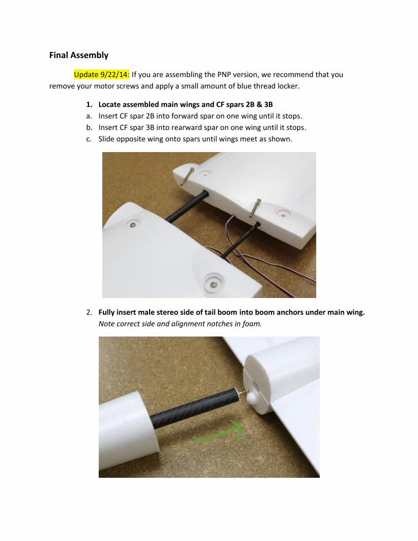
1. Locate assembled main wings and CF spars 2B & 3B
a. Insert CF spar 2B into forward spar on one wing until it stops.
b. Insert CF spar 3B into rearward spar on one wing until it stops.
c. Slide opposite wing onto spars until wings meet as shown.
2. Fully insert male stereo side of tail boom into boom anchors under main wing.
Note correct side and alignment notches in foam.

a. Once fully inserted, tighten down clamps with 2.5mm tool.
3. Slide ruddervators onto rear portion of tail booms
a. Tighten clamps once fully inserted and no gaps in foam are showing.
i. This may be more difficult during the first installation.
b. Plug male servo leads into female plugs in rear of tail boom.
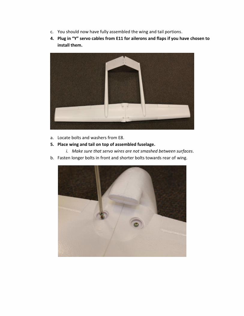
c. You should now have fully assembled the wing and tail portions.
4. Plug in “Y” servo cables from E11 for ailerons and flaps if you have chosen to
install them.
a. Locate bolts and washers from E8.
5. Place wing and tail on top of assembled fuselage.
i. Make sure that servo wires are not smashed between surfaces.
b. Fasten longer bolts in front and shorter bolts towards rear of wing.
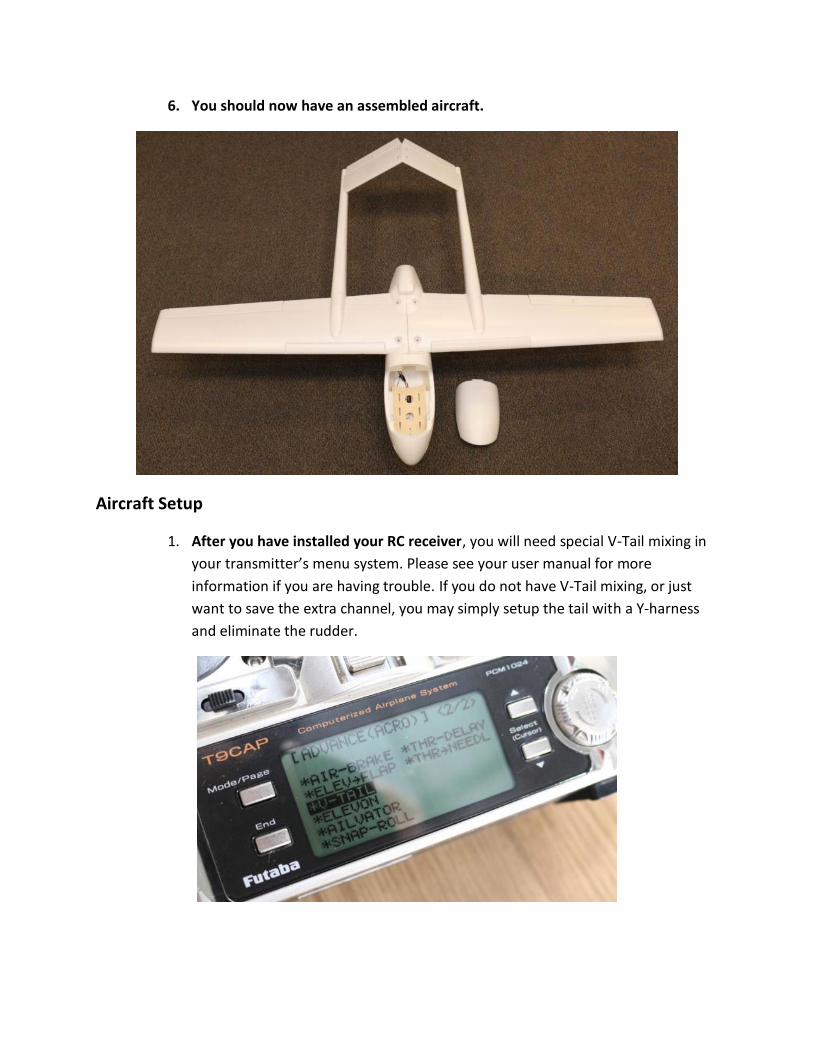
6. You should now have an assembled aircraft.
Aircraft Setup
1. After you have installed your RC receiver, you will need special V-Tail mixing in
your transmitter’s menu system. Please see your user manual for more
information if you are having trouble. If you do not have V-Tail mixing, or just
want to save the extra channel, you may simply setup the tail with a Y-harness
and eliminate the rudder.

2. After attaching all equipment and batteries, be sure to check for proper center
of gravity before taking off for the first time. The best CG we have found is at
45mm measured from behind the leading edge flap shown below. This
measurement is slightly behind the main spar. For your first flight, we
recommend setting CG directly on the main spar (slightly nose heavy).
3. Control Surface end point adjustment
a. For our personal preference, we use 100% travel on all of our end points for the
Anaconda. We suggest that if your RC transmitter has the capability, to use a 2
or 3 position switch to set throws at 60% and 80%. This will allow you to change
mid-flight if you find that you have too much or too little control over the
aircraft.
b. If you are using flaps, you may wish to have a 5-10% downward mix in the
elevator. This will help eliminate any “ballooning” effect when applying flaps.
Experiment with the flaps at higher altitude before attempting to land to see
how the plane reacts to your setup.
As a reminder, please DO NOT attempt to hand launch this aircraft. It is simply too large
and unwieldy to try it.
Thank you for your purchase and enjoy your RMRC Anaconda!