Embed Size (px)
Citation preview

U.P. POWER TRANSMISSION CORPORATION, LTD.
TENDER DOCUMENT
FOR
CONSTRUCTION OF 400 KV DOUBLE CIRCUIT QUAD TRANSMISSION LINE
FROM 765 KV GREATER NOIDA S/S (UNDER CONSTRUCTION)
TO 400 KV GREATER NOIDA S/S (PALI)
(55 KMS)
SUPERINTENDING ENGINEER ELECTRICITY 765&400 KV TRANSMISSION DESIGN CIRCLE
U.P. POWER TRANSMISSION CORPORATION, LTD. 10TH FLOOR, SHAKTI BHAWAN, 14 ASHOK MARG,
LUCKNOW – 226001
Price : Rs. 10500/- (Cost of Tender Document : Rs. 10000/- VAT : Rs. 500/-)

ETD8-24/14 Page 2
INDEX
S. NO. DESCRIPTION PAGE
TENDER NOTICE 3-4
1. PART – I
GENERAL CONDITIONS OF CONTRACT & FORM ‘A’
5
i) SECTION – 1 : INSTRUCTION TO TENDERS 6-42
SCHEDULE OF PRICES 43-54
ii) SECTION – 2 : GENERAL REQUIREMENTS OF SPECIFICATION
(COMMERCIAL)
55-58
iii) SECTION – 3 : GENERAL REQUIREMENTS OF SPECIFICATION
(TECHNICAL)
59-65
iv) SECTION – 4 : GENERAL REQUIREMENTS OF SPECIFICATION
(ERECTION)
66-73
v) FORM ‘A’ 74-100
2. PART – II : SPECIAL CONDITIONS OF CONTRACT 101
SECTION – 1 : DETAILED PRE-QUALIFYING REQUIREMENTS 102-126
SECTION – 2 : GENERAL CONDITIONS 127-147
SECTION – 3 : PRICE 148-153
IEEMA PRICE VARIATION FORMULA (APPENDIX-I,II,III,IV) 154-160
3. PART – III
VOL-1 : TECNICAL CONDITIONS OF CONTRACT&
TECHNICAL SPECIFICATION OF TOWER AND
HARWARES AND ITS
ACCESSORIES,INSULATORS
161-391
VOL-2 : TECHNICAL SPECIFICATION OF OPGW AND
ITS HARWARES AND ACCESSORIES
392-487

ETD8-24/14 Page 3
TENDER NOTICE

ETD8-24/14 Page 4
UP Power Transmission Corporation Limited
TENDER NOTICE No. - ETD 8-24/14
Sealed tenders, in duplicate, in two parts (Part-1 & Part-2) are invited for construction of approximately 55 km. of 400 kV Double Circuit (QUAD MOOSE) Transmission line from 765 kV Greater NOIDA S/S (under construction) to 400 kV Greater NOIDA S/S (Pali) on Turnkey Basis. The job includes construction of above lines on Turn-Key basis including supply of following materials:– 1. Towers, Bolts &Nuts, Tower Accessories8 2. Hardware fittings 3. Insulators 4. Earthing Materials 5. Conductor and Earthwire Accessories 6. OPGW and its Hardware and Accessories 7. Material to meet Aviation requirement
The supply of ACSR Moose Conductor and 7/3.66 MM GS Earthwire is excluded from the scope of Tenderer. The Tender Document will be available on UPPTCL website “www.upptcl.org” on or after 17-05-2014 for downloading. In case documents have been down loaded from the website the bidder has to submit with Part-I tender fee of Rs.10500/-(Tender Cost Rs.10000.00+VAT @ 5%) in form of Bank draft in favour of U. P. Power Transmission Corporation Ltd, Lucknow (Account No. 30231982762, IFS Code SBIN0003347) payable at Lucknow. Tender Document may also be collected in hard copy from this office on payment of Rs. 10500/- in form of Bank draft as per details mentioned above.
Tenders shall be received up to 15.00 hrs on 17.06.2014 and Part-I of the same shall be publicly opened at 15.30 hrs. on the same day. In case opening date happens to be a holiday, tenders shall be received and opened on the next working day at the same time. Date of opening of Part-II of qualified bidders shall be intimated later on. For any other corrections / amendments/ modifications/ extensions etc. please visit our web site www.upptcl.org till the date of submission of tenders.
Superintending Engineer, Electricity 400 kV & 400kV Transmission Design Circle,
U.P. Power Transmission Corporation Ltd. 10th Floor, Shakti Bhawan Extension, 14-Ashok Marg, Lucknow- 226001,
Uttar Pradesh, India.
SAVE ENERGY IN THE INTEREST OF NATION

ETD8-24/14 Page 5
PART – I
GENERAL CONDITIONS OF CONTRACT
&
FORM – A

ETD8-24/14 Page 6
SECTION – 1
INSTRUCTIONS TO TENDERERS
1.1 PREPARATION OF TENDER
1.1.1 Before submission of the Tender, the tenderers are required to make themselves fully conversant with the Technical Specifications, Drawings, Special Instructions to tenderers, Instruction to tenderers, General requirement of Specification including Schedules and General Conditions of the Contract Form A so that no ambiguity arises at a later date in this respect..
1.1.2 Any inconsistency or ambiguity in the offers made by the Tenderer shall be interpreted
to the maximum advantage of UPPTCL and disadvantage of the Tenderer. The Tenderer shall have no right to question the interpretation of the Purchaser in all such cases and the same shall be binding on the tenderers.
1.1.3 The tenders should be prepared and submitted strictly in accordance with the
instructions contained in these specifications. The tender shall be complete in all respects. Tender must be submitted in the manner specified on the attached prescribed schedules and/ or copies thereof. To complete the proposal, the tenderer must fill the tender form, declaration, all schedules and data sheets, annexed with the specification item by item in accordance with the instructions and notes supplementary thereto. The interpolations, insertion, cutting and corrections made in the tender offers should be duly initialled by the tenderer.
1.1.4 Each tenderer shall supply the data required in sheets annexed with the specification by typing at appropriate places against each item to facilitate preparation of comparative statements. These sheets must be properly signed by authorized representative of the tenderer / manufacturer testifying the data submitted. All schedules must be duly filled in and shall be enclosed with each copy of the tender. In case the tenderer does not supply any of the required information at the time of tender, necessary loading may be made while evaluating the prices of his offer without giving them any further opportunity to supply or clarify the same. The tenderers are notified that in case the required information are not furnished in the specified proforma / schedules attached with the specification, the Purchaser shall not be responsible for any error in the evaluation of their tenders on this account. Further, failure to comply with this requirement may result in the rejection of the tender at the discretion of the Purchaser.
1.1.5 A set of technical, descriptive and illustrative literature along with drawings must accompany each copy of the tender so that a clear understanding of the equipment offered is obtained. The tenders sent by post must be posted by Registered Post A/D sufficiently in advance so as to reach the Purchaser by the scheduled date and time of submission of the tender. Any tender received after the date and time of submission even on account of postal delay shall not be opened. The tenderers are, therefore, requested to ensure in their own interest that the tenders are delivered in time.
Telegraphic Tenders shall not be considered under any circumstances.
1.2 PREQUALIFYING CONDITIONS: Tenderers meeting the following conditions only will be considered:

ETD8-24/14 Page 7
1.2.1 QUALIFICATION OF TENDERER:
1.2.1.1 The Tenderer shall either themselves be manufacturers of the equipment offered or accredited representative of such manufacturers in India or of their Principals abroad with whom they may be having collaboration. Such accreditation should be at least of one year on date of tendering.
1.2.1.2 Relevant documents in support of the above must be furnished along with undertaking of the manufacturer. If these documents are not furnished along with the tenders, the offer will be liable to be rejected summarily.
1.2.2 (A) OPERATIONAL EXPERIENCE: (i) Offered equipment should have given three years proven trouble free
operational service in tropical climate, (ii) In case of equipment being manufactured in India under valid FOREIGN
COLLABORATION, operating experience in tropical climate of offered collaborator’s equipment shall also be acceptable provided copy of valid collaboration agreement for the equipment offered is submitted with the Tender.
(iii) In case of offer of imported equipment, the three years operating experience will be
considered in respect of those areas only which are similar to tropical conditions prevailing in India.
(B) MANUFACTURING EXPERIENCE:
The indigenous manufacturers or their foreign collaborator must have manufactured at
least 20% of specified quantities of each item of identical or similar equipment. 1.2.3 TESTING FACILITIES: The tenderer must have all necessary facilities at their works for carrying out such
routine and acceptance tests as prescribed in the relevant ISS and any other routine and acceptance test as specified in the specification. Documentary evidence of existence of such facilities should be filed along with the tender.
1.2.4 TYPE TESTS
(A) TYPE TEST FOR INDIGENOUS OR FULLY IMPORTED BIDS
The offered equipment must have been fully type tested as per relevant ISS and/ or any other specified international standards, during the last five years period reckoned from the date of opening of the tender. Photocopy of such type test reports/ certificates must be submitted alongwith the tender bid. The type test certificates of prototype manufactured and tested by foreign collaborators of the tenderers at their works shall not be acceptable for indigenously manufactured equipment.
(B) For bids under 1.2.2(A) :
(i) The offered indigenously manufactured or collaborators manufactured equipment should have been type tested and reports submitted with tender.
ETD8-24/14 Page 8
(ii) The collaborator’s equipment shall have three years operating experience under tropical climate.
1.2.5 For those indigenous manufacturers who have neither manufactured 20% quantity indigenously and nor got their equipment type tested but are qualifying because of their foreign collaborator’s manufacturing experience and type testing, the maintenance period shall be 54 months from the date of receipt of material at site or 48 months from the date of commissioning, whichever is earlier, instead of 18 months and 12 months respectively as provided under clause 30 of Form-‘B’.
1.2.6 The purchaser at his discretion may consider awarding a trial order of small quantity to those bidders who have proven design and meet the requirement of clauses 1.2.1, 1.2.3 and 1.2.4 (A). Such suppliers shall continue to be eligible for trial orders under this clause till their equipment has given three years trouble free operational service.
1.2.7 DATE OF CONSIDERATION :
1.2.7.1 The above cited experience and manufactured quantities shall be counted as on the date of opening of the tender.
1.2.8 All statements and claims should be duly supported by authenticated copies of documents without which the tender is liable to be rejected summarily.
1.3 SUBMISSION OF TENDER:
1.3.1 The Tenderers shall submit their tender in duplicate in two separate parts. Each part shall be kept in double cover, inner one being sealed.
(i) TENDER BID PART-I:
This part shall contain Earnest Money, Technical and Commercial particulars, Prequalifying details of the tender, quantity and Delivery Offered. The cover containing this part of the bid shall be superscribed: “TENDER BID PART – I (Earnest Money, Technical, Commercial and Pre-qualifying details etc.)”
(ii) TENDER BID PART- II:
This part shall contain prices only and the cover containing this part shall be superscribed: “TENDER BID PART – II (PRICES)”.
1.3.2 The envelopes of both the parts shall be kept in another envelope which shall also be sealed and super scribed on top as under:
“TENDER FOR ERECTION OF 400 KV TRANSMISSION LINES ON TURN-KEY BASIS EXCLUDING SUPPLY OF CONDUCTOR & EARTHWIRE AGAINST SPECIFICATION NO: ETD 8-24/14. Due for opening on (date) 17.06.2014”
1.3.3 TENDER BID PART– I (EARNEST MONEY, TECHNICAL, COMMERCIAL AND PREQUALIFYING DETAILS ETC.):

ETD8-24/14 Page 9
1.3.3.1 Earnest Money for full tendered quantity of 55 Km shall be Rs. 42.00 Lacs.Any Tenderer who deposits Earnest Money for less than 42.00 Lacs or quotes quantity of less than 55 KM shall not be considered. Earnest Money shall be furnished in following manner:-
(a) Bank Draft drawn in favour of U. P. Power Transmission Corporation Ltd, Lucknow (Account No. 30231982762, IFS Code SBIN0003347) payable at Lucknow.
OR (b) Bank Guarantee from a scheduled bank in India, executed on a Non-Judicial
Stamp Paper worth Rs: 100/- as per U.P.Stamp Act, on the specified proforma appended with Form-‘B’(only applicable when amount of Earnest Money exceeds Rs. 5000/-).Please refer clause no. 1.6 of Part-II, Section-2 “Special Conditions of the Contract” for furnishing Earnest Money. Bank Guarantee shall be valid for six months from date of opening of tender with further three months claim period.
1.3.3.2 Any deviation from/ or addition to the text of the specified proforma of Bank Guarantee shall render the Bank Guarantee invalid for the purpose of opening of Tender Bid Part-II.
1.3.3.3 Offers without Earnest Money shall not be considered under any circumstances.
1.3.3.4. Besides the Earnest Money, other relevant information and following documents duly filled in must also accompany the Tender Bid Part-I.
1 Schedule A : Tender Form 2 Schedule B : Documents regarding prequalifying details of the
tenderer. 3 Schedule C : Declaration 4 Schedule
D : Proforma for Joint Undertaking by collaborator/
associates with the Tenderer. 5 Schedule E : General Particulars 6 Schedule F : List of Drawings / literature enclosed with the tender. 7. Schedule G : Deviations from ‘Instructions to Tenderers’
8. Schedule H : Deviations from ‘General Requirement of Specification (Commercial)’
9. Schedule I : Deviations from ‘General Requirement of Specification (Technical)’
10. Schedule J : Deviations from ‘General Requirement of Specification (Erection)’
11. Schedule K : Deviations from ‘General Conditions of Contract’ Form– ‘A’
12. Schedule L : Deviations from ‘Special Conditions of Contract’ 13. Schedule M : Deviations from ‘Technical Specifications’
14. Schedule’ N : Schedule of completion period
15 Income Tax Clearance certificate.

ETD8-24/14 Page 10
1.3.4 TENDER BID PART – II (PRICES):
1.3.4.1 Only the prices and the following documents duly filled in must accompany Tender Bid Part – II:
1 Schedule G : The price incidence of Deviations from ‘Instructions
to Tenderers 2 Schedule H : The price incidence of Deviations from ‘General
Requirement of Specification(Commercial)’
3 Schedule I : The price incidence of Deviations from ‘General Requirement of Specification (Technical)’
4 Schedule J : The price incidence of Deviations from ‘General Requirement of Specification (Erection)’
5 Schedule K : The price incidence of Deviations from ‘General Conditions of Contract’ Form– ‘A’
6 Schedule L : The price incidence of Deviations from ‘Special Conditions of Contract’
7 Schedule M : The price incidence of Deviations from’ Technical Specifications’
8 Schedule N : Schedule of quantity and price (Price Schedule)
1.3.4.2 On the date of the tender opening at appointed time, Part– I of the tender shall be
opened publicly in the presence of the authorized representative of the bidders. The date and time of opening of Tender Bid Part-II shall be intimated separately, later on.
1.3.4.3 Any action on the part of the tenderers to revise the prices and/ or change the structure of price(s) at his own instance after the opening of the tender may result in rejection of the tender and/ or debarring the tenderer from participation in purchases by the Corporation for one year in the first instance.
1.4 VALIDITY: 1.4.1 The tenders shall be valid for a period of six (6) calendar months from the date of
opening of the Part-I or any extended date of opening. Tenders with lesser validity are liable to be rejected.
1.5 PRICES AND PRICE STRUCTURE: 1.5.1 The Tenderer must quote F.O.R. Destination prices of all the items (along with F.O.R.
works prices) for despatch to any Railway Station along the route of the transmission line in U.P. The unit F.O.R. destination price shall comprise of the following components:
(a) Ex-Works Prices (b) Packing and Forwarding Charges (c) Railway/ Road Freight (d) Transit Insurance charges against all risks (e) Insurance Charges for 45 days storage after receipt of equipment at destination
stores/ substation against all risks.

ETD8-24/14 Page 11
The tenderers must clearly specify these components individually besides F.O.R. destination prices.
1.5.2 TAXES AND DUTIES: 1.5.2.1 The quoted prices should be exclusive of all Taxes, Duties and Octroi Charges etc.
which will be reimbursed at actuals on production of relevant original vouchers. However the Tenderer must indicate the rates of various taxes/ duties leviable, as on the date of tender opening, on various price components as given in Price Schedule. Form-‘C’/‘D’ will be obtained by the contractor from the concerned consignee. In no case Form-‘C’/‘D’ will be demanded through Bank.
1.5.3 PRICE VARIATION: 1.5.3.1 The tenderers are required to quote variable prices only without ceiling limit on either
side unless specified otherwise under ‘Special Conditions of contract’. The price variation shall be admissible as per latest relevant IEEMA price variation formula as applicable for the equipment (of the tendered capacity and rating).
1.5.3.2 The ruling date of basic prices of raw materials published in IEEMA Circulars shall be
the date as on First working day of the calendar month, one month prior to the date of tendering. The Tenderer shall furnish a photocopy of the IEEMA Circular of basic rates of raw materials and the latest IEEMA price variation clause as applicable along with Bid Part-II.
1.5.3.3 In case there is no IEEMA price variation clause for the said equipment, the price
variation formula as given under ‘Special Conditions of contract’ shall be applicable. No other price variation formula shall be accepted under any circumstances.
1.5.3.4 The price variation shall be allowed on Ex-Works prices only for the contractual delivery period.
1.5.3.5 The component of packing and forwarding, freight and insurance charges shall remain FIRM in all respects throughout the currency of the contract.
1.5.3.6 Tenderer shall quote FIRM prices only for spare parts, type tests, and service charges for erection and commissioning of the equipment.
1.5.3.7 No price variation shall be claimed against documents to be negotiated through bank.
1.5.3.8 Bank Charges, if any, for documents to be negotiated through bank, shall be borne by the Tenderer.
1.5.3.9 In the event of dispatch of equipment beyond contractual delivery period, the claims shall be raised only after allowing for the due price reduction as per provisions of the order.
1.6 EVALUATION OF TENDER: 1.6.1 In comparing tenders and making awards, the purchaser may consider such factors as,
compliance with specifications, relative quality and adaptability of suppliers or services, experiences, record of integrity in dealing, ability to furnish repairs and maintenance service, the time of delivery, capability to perform and available facilities such as adequate shops, equipment, plant, technical organization etc.

ETD8-24/14 Page 12
1.6.2 In case prices of some items are given in lump sum where unit prices are required,
purchaser reserves the right to evaluate unit prices on the basis of quoted lump sum prices.
1.6.3 In case where tenderer does not quote F.O.R. destination prices asked for, their quoted unit prices shall be loaded by appropriate additional factors on Ex-Works prices as below:
(a) Packing Charges @ 0.75 %
(b) Forwarding Charges @ 0.25 %
(c) Freight for first 500 km @ 2.0 %
(d) Freight for every next 250 km @ 0.5 % or part thereof
(For this purpose distance shall be taken from supplier’s station to Lucknow and in case the distance is less than 500 km loading shall be done for a minimum distance of 500 km).
(e) Transit Insurance @ 0.5 %
(f) Insurance for 45 days storage after receipt of equipment at destination station @ 0.5%
1.6.4 Since the tenderers have been asked to quote unit variable (Ex-Works) prices only
without any ceiling limit on either side, no advantage shall be given to those tenderers who quote either ‘FIRM’ prices or ‘VARIABLE PRICES WITH CEILING’.
1.6.5 No payment prior to dispatch of materials shall be made by the Corporation under any
circumstances. Tenderers are advised not to ask for any such advance payment. Request for such advance payment will not be considered even if the tenderers are willing to pay interest charges thereon. Tenderers asking for advance payments are liable to be rejected.
1.6.6 The ruling date of basic prices of raw materials for the price variation purposes shall be
same for all the offers (as specified in Clause No. 1.5.3.2 of these instructions). In case, it is prior to the notified date, the quoted Ex-Works price shall be brought as per IEEMA formula. However no loading shall be considered for dates mentioned beyond the notified date.
1.6.7 Any rebate/ discount linked with quantity, terms of payment, any condition shall not be considered for the purpose of evaluation and of such offers vis-a-vis others. However, the same may be availed while placing order with such successful tenderers.
1.6.8 If the tenderers fail to quote prices for any of the item(s)/ component(s) as asked for or confirm its supply, the highest prices as quoted by other tenderer for the same shall be added to arrive at F.O.R. destination computed price of such tenderers for comparison purpose only.
1.6.9 The prices shall be compared inclusive of Excise Duty and Sales Tax/ Trade Tax.
1.6.10 Loading on any account as may be deemed necessary in the opinion of the Purchaser to bring the various offers at par to each other for comparison purposes may be done at the discretion of the Purchaser.

ETD8-24/14 Page 13
1.7 SPLITTING OF ORDER: 1.7.1 The Purchaser reserves the right to split the order among various tenderers in any
manner it chooses without assigning any reason. 1.8 AWARD OF CONTRACT: 1.8.1 The Purchaser is not bound to accept the lowest or any tender and may reject any or all
the tenders without assigning any reason. 1.8.2 The successful tenderers, if required to do so, may have to enter into a contract
agreement with the Purchaser as per General Conditions of Form-‘A’/ ‘B’ and other Special Conditions attached with the Tender Specifications.
1.8.3 For signing the contract a duly authorized representative of the successful tenderer shall be required to sign and accept the Contract at Lucknow at a reasonable notice.
1.8.4 Tenderers shall ensure to put initials on each and every page of the tender, last page of each document forming part of the tender shall bear full signature under official seal fully disclosing the name, designation and relationship with the firm of the signatory. In case of a partnership concern the tender may be signed by all the partners of the firm or by one of them holding Power of Attorney (Copy to be furnished with the offer). In case of Corporations/ Companies, the tender may be signed either by the President or Secretary or any such person authorized to tender in the legal name of the corporation/ company (Copy of such authority to be furnished along with offer)
Besides, the tenderers shall also furnish the following information:
i) Name, designation, profession with Postal Addresses of all the Partners/ Directors and other persons authorized to conduct business in respect of this tender.
ii) Postal Addresses of the firm’s works, Registered Head Office, Sales Office, Local Offices etc.
iii) Names and Postal Addresses of their authorized local representative/ Liaison Officers.
1.9 INCOME TAX AND SALES TAX CLEARANCE CERTIFICATES : 1.9.1 The Tenderer shall furnish with the Tender, Income Tax and Sales Tax Clearance
Certificates of current as well as preceding year, from the competent authority.The Purchaser reserves the right to reject any Tender if Income Tax/ Sales Tax Clearance Certificates are not furnished or the reasons for the Tenderers’ inability to furnish such certificates are not given in the Tender.
1.10 DEVIATIONS: 1.10.1 The offer should be strictly in line with the conditions, specifications and other
requirements mentioned in the Tender Specification document. No deviations are permitted except under special circumstances. Should the Tenderer wish to depart from the General Requirements or Technical Specifications or General Conditions of Contract Form – ‘A’/ ‘B’in any way he must draw specific attention to such departure(s). All such deviations shall specifically be filled up in the relevant Deviation

ETD8-24/14 Page 14
Schedule. If deviations are not specifically recorded in these Schedules and submitted along with tender document, it will be presumed that there are no deviations and the interpretation will be binding upon the Tenderer.
1.10.2 Purchaser is, however, not bound to accept all or any deviations as mentioned in such
Schedules. Tenderers are also advised not to enclose their own standard or printed conditions for sale etc. as the same shall not be considered.
1.11 CANVASSING: 1.11.1 No tenderer shall canvass any Corporation’s Official or Engineer, with respect to his
own or other’s tenders. Contravention of this condition will result in rejection of the Tender. This clause shall not be deemed to prevent the tenderer from supplying to the Engineer any further information/ clarification asked for by the Engineer.
1.12 COURT OF COMPETENT JURISDICTION:
1.12.1 All disputes arising out of and touching or relating to the subject matter of agreement shall be subject to the jurisdiction of Local Courts of Lucknow and High Court of Judicature at Allahabad only.
1.13 ARBITRATION CLAUSE 31 OF FORM -B/CLAUSE 38 0F FORM-A 1.13.1 The following is deemed to be added at the end of Para-I in the Arbitration clause no.38
of Form-A.
‘In case of refusal/ neglect by such nominee, Chairman UPPTCL may nominate another person in his place.’

ETD8-24/14 Page 15
SCHEDULE – ‘A’ TENDER FORM
FOR SUPPLY / SUPPLY & ERECTION OF EQUIPMENT
From: To: The Superintending Engineer, Electricity 400& 400 kV Transmission Design Circle U.P.Power Transmission Corporation Limited Lucknow. Sir, With reference to your invitation to tender for the above, I/ We hereby offer to the U. P.
Power Transmission Corporation Ltd., the items in the Schedule of Prices and delivery annexed or such portion thereof as you determine in strict accordance with the annexed Conditions of the Contract Form – ‘A’, specifications and schedules of Rates to the satisfaction of the Purchaser or in default thereof to forfeit and pay to U.P.Power Transmission Corporation Ltd., the sum of money mentioned in the said conditions.
The rates quoted are inclusive pro-rata and in full satisfaction of all claims.
I / We agree to abide by tender for the period of six months from the date fixed for receiving of the same:
A sum of Rs. . . . . . . . . . . . . . . . . . . . in the form of Bank Draft/ Bank Guarantee is herewith forwarded duly endorsed in favour of the. . . . . . . . . . . . . . . . . . . . . . . . . . . . . . U.P.Power Transmission Corporation Ltd., Lucknow as Earnest Money.
I / We hereby undertake and agree to execute a contract in accordance with the conditions of the contract.
Encl: As above
Dated . . . . . . . . . . . . . . . day of . . . . . . . . . . . . . . . 200. . Yours faithfully,
Witness (Signature of the tenderer in full)
Address Name

ETD8-24/14 Page 16
SCHEDULE – ‘B’
PRE QUALIFICATION DETAILS OF THE OFFER 1. EXPERIENCE: No.
Brief Technical details of equipment
No. of years of Experience of manufacturer
Name &complete address of purchaser (copy of
performance reports be enclosed)
Date of supply & quantity
Name of Transmission line where installed & date of
commissioning
Period of trouble free operation
Copy of type test reports
(enclosed /not enclosed)
2. TESTING FACILITIES: Sl. No.
Name of test Details of testing equipment available
Range up to which tests can be Performed
Place of testing
(i) Routine:
(a) (b) (c)
(ii) Acceptance: (a) (b)
(c) (iii) Type
(a) (b) (c)
Note: In case testing facility is not available at the Works of tenderer, place where such tests would be carried out is to be specified:
Company Seal
Full Signatures Name
Designation

ETD8-24/14 Page 17
SCHEDULE – ‘C’
DECLARATION
(To be executed on Non-Judicial Stamp Paper of Rs: 10/- with revenue stamp of Re. 1/- affixed)
Tender invited by :
Tender for :
Name of Tenderer :
Specification Number :
and date of opening
In consideration of the U.P.Power Transmission Corporation Ltd. having treated the Tenderer to be an eligible person whose tender may be considered, the Tenderer hereby agrees to the condition that the proposal in response to the above invitation shall not be withdrawn within six months (or any extension thereof) from the date of opening of the tender, also to the condition that if thereafter the Tenderer does withdraw his proposal within the said period, the Earnest Money deposited by him may be forfeited to the U.P.Power Transmission Corporation Ltd. and at the discretion of the Purchaser, the Purchaser may debar the tenderer from tendering for a minimum period of one year reckoned from the date of opening of the tender.
Signed this . . . . . . . . . . . . . . . . . . . day of. . . . . . . . . . . . . . . . . . of year 20….. .
Place………………………. Signed by: . . . . . . . . . . . . . . . . . . .
Witness: Tenderer:
Name: Designation:

ETD8-24/14 Page 18
SCHEDULE – ‘D’
(PROFORMA FOR JOINT UNDERTAKING BY THE COLLABORATOR/ASSOCIATE AND THE TENDERER)
(To be stamped in accordance with U. P. Stamp Act) To, The Superintending Engineer, Electricity 400& 400 kV Transmission Design Circle U.P.Power Transmission Corporation Limited Lucknow.
Dear Sirs, In terms of ‘Instructions to Tenderer’ in the Specification No: for the design,
manufacture, testing, delivery, erection and commissioning (as specified), of . . . . . . . . .. . . . . . . . . . . . . . . . . . . . . . . . . . . . . . . . . . . . . . . . . . . . . . . . . . . . . . . . . . . . (Name of Equipment)
It is a condition that the tenderer as well as their collaborator/ associate shall jointly and severally undertake the responsibility for the successful performance of the Contract (hereinafter referred to as Contract) which is qualified for the award on the basis of expertise of collaborator/ associate.
We, . . . . . . . . . . . . .. . . . . . . having our Registered Office at . . . . . . . . . . .(hereinafter referred to as a Collaborator/ Associate ) which in turn, shall include our successor, administrator, recruiter and assign and we . . . . . . . . . . . . . . . . . . .having our Registered Office at . . . . . . . . . . . . . . . ( hereinafter called Tenderer/ Contractor ) are held jointly and severally liable and bound to U.P.Power Transmission Corporation Ltd. (hereinafter referred to as Purchaser) which expression shall include its successor, administrator and assign, for the successful performance of the contract including the overall responsibility for design, manufacture, testing, delivery, performance etc. of . . . . . . . . . . . . . . . . . . (Name of equipment) in accordance with the Contract.
The collaborator/ Associate hereby agree to depute their technical experts from time to time to Contractor’s Works/ Project site as mutually agreed upon between the Purchaser and the Contractor in order to discharge the Contractor’s obligations as stipulated in the Contract. The Tenderer and the Collaborator/ Associate hereby agree that this undertaking shall be irrevocable and it shall form an integral part of the Contract.
In WITNESS thereof the Collaborator/ Associate and the Tenderer have through their authorized representative, set their hands and seal on this . . . . . . . . . . . . . . . . . . . day of . . . . . . . . . . . . . . . . . the year 20 .
For Tenderer For Collaborator / Associate
Signatures Signatures Name Name Designation Designation (Seal) (Seal) Witness signature: Witness signature: Name & Address: Name & Address:

ETD8-24/14 Page 19
SCHEDULE‘E’ (SUPPLY)
SCHEDULE OF GENERAL PARTICULARS
Sl. No.
Description
Requirement as per specification
Offered by Tenderer
1 2 4 5
1 Name of the Tenderer:
2 Registered Office
3 Postal address
4 Telegraphic address
5 FAX No./E-mail
6 Name and address of Manufacturer, if any
7 Location and address of works
8 Name and address of local representative and his telephone number, if any
9 Name and address of the officer of the tenderer /manufacturer to whom all reference shall be made for expeditious coordination
10 Place from where service facility and
spares are available (Give full address)
11 Whether the tenderer is sole proprietor/ partnership concern/ Pvt.Ltd. company/ public undertaking
12 Name of foreign collaborator, if any
13 Whether the designs are their own or obtained from other sources. If from other sources, the same may be indicated.
14 Name and address of the sub- supplier
15 Name, designation, qualification and experience of the engineer employed by the tenderer in design, development and manufacturing of the quoted equipment
16 Authorized capital of the company
17 Actual production per year of the equipment quoted
18 Manufacturing capacity per month of the quoted equipment (item wise)
ETD8-24/14 Page 20
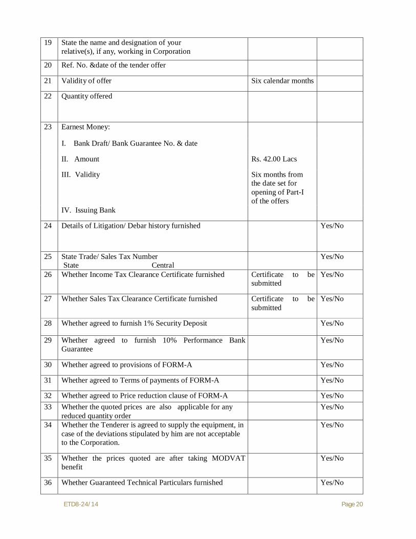
19 State the name and designation of your relative(s), if any, working in Corporation
20 Ref. No. &date of the tender offer
21 Validity of offer Six calendar months
22 Quantity offered
23 Earnest Money:
I. Bank Draft/ Bank Guarantee No. & date
II. Amount Rs. 42.00 Lacs
III. Validity
Six months from the date set for opening of Part-I of the offers
IV. Issuing Bank
24 Details of Litigation/ Debar history furnished Yes/No
25 State Trade/ Sales Tax Number State Central
Yes/No
26 Whether Income Tax Clearance Certificate furnished Certificate to be submitted
Yes/No
27 Whether Sales Tax Clearance Certificate furnished Certificate to be submitted
Yes/No
28 Whether agreed to furnish 1% Security Deposit Yes/No
29 Whether agreed to furnish 10% Performance Bank Guarantee
Yes/No
30 Whether agreed to provisions of FORM-A Yes/No
31 Whether agreed to Terms of payments of FORM-A Yes/No
32 Whether agreed to Price reduction clause of FORM-A Yes/No 33 Whether the quoted prices are also applicable for any
reduced quantity order Yes/No
34 Whether the Tenderer is agreed to supply the equipment, in case of the deviations stipulated by him are not acceptable to the Corporation.
Yes/No
35 Whether the prices quoted are after taking MODVAT benefit
Yes/No
36 Whether Guaranteed Technical Particulars furnished Yes/No

ETD8-24/14 Page 21
37 Whether agreed to Completion Period Yes/No
38 Mode of Despatch By Road
39 Any other information
Full Signatures
Name Designation
Date Seal of Company

ETD8-24/14 Page 22
SCHEDULE ‘E’ SCHEDULE OF GENERAL PARTICULARS (ERECTION)
Sl.No
Description Reference of clauses of
specification
Requirement as per specification
Offered by
Tenderer 1 2 3 4 5
1 Name of the Tenderer:
2 Registered Office
3 Postal address
4 Telegraphic address
5 FAX No./ E-mail 6 Name and address of local
representative & telephone No.
7 Name and address of the officer of the tenderer/manufacture to whom all reference shall be made for expeditious coordination
8 Whether the tenderer is Sole Proprietor/ Partnership Concern/ Pvt.Ltd. company/ Public Undertaking
9 Name of Foreign Collaborator, if any
10 Name, designation, qualification and experience of the engineer employed by the tenderer in design, development and manufacturing of the quoted equipment
11 Authorised Capital of the company
12 Annual Turnover per year (Rs.) 13 State the Name and designation of
your relative(s), if any, working in corporation
14 Ref. No.&Date of the Tender Offer
15 Validity of offer 1.4 of Part-I, Section-1
Six calendar months
16 Quantity offered
17 Earnest Money: 1.6 Of Part-II,

ETD8-24/14 Page 23
I. Bank Draft/Bank Guarantee No. & date
Section-2
II. Amount III. Validity
Six months from the date set for opening of Part-1 of the offers
IV. Drawee/ Issuing Bank 18 Qualifying Requirements
Qualification of the Tenderer
As per clause no. 3.0 of SCC (Part-II, Section-1)
Yes/No
19 State Trade/ Sales Tax Number State Central
20 Whether Income Tax Clearance Certificate furnished
1.9 of Part-I, Section-1
Certificate to be submitted
Yes/No
21 Whether Sales Tax Clearance Certificate furnished
1.9 of Part-I, Section-1
Certificate to be submitted
22 Whether agreed to furnish 1%Security Deposit
2.4 of Part-I (section-2)
Yes/No
23 Whether agreed to furnish 10% Performance Bank Guarantee
2.5 of Part-I (section-2)
Yes/No
24 Whether agreed to Provisions of FORM-A
Part-I Yes/No
25 Whether agreed to Terms of Payments
25 of FORM-A Read alongwith 2.2.3 of SCC, Section-3
Yes/No
26 Whether agreed to Damages for Delay in Completion
2.9 of Part-I (section-2) and clause 32 of FORM-A
Yes/No
27 Whether the quoted prices are also applicable for any reduced quantity order
Yes/No
28 Commercial Deviations, if any 29 Technical Deviations, if any 30 Whether the Tenderer is agree to
supply the equipment, in case of the deviations stipulated by him are not acceptable to the Corporation.
Yes/No
31 Whether the prices quoted are after taking MODVAT benefit
Yes/No
32 Whether Guaranteed Technical Yes/No
ETD8-24/14 Page 24
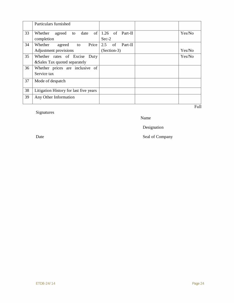
Particulars furnished
33 Whether agreed to date of completion
1.26 of Part-II Sec-2
Yes/No
34 Whether agreed to Price Adjustment provisions
2.5 of Part-II (Section-3)
Yes/No
35 Whether rates of Excise Duty &Sales Tax quoted separately
Yes/No
36 Whether prices are inclusive of Service tax
37 Mode of despatch
38 Litigation History for last five years 39 Any Other Information
Full Signatures Name
Designation
Date Seal of Company

ETD8-24/14 Page 25
SCHEDULE – ‘F’
LIST OF DRAWINGS & LITERATURE ENCLOSED WITH THE TENDER
S.N. Drawing/Literature Number Title
Seal of the Company Signature
Name:
Dated: Designation:

ETD8-24/14 Page 26
SCHEDULE – ‘G’
DEVIATIONS FROM ‘INSTRUCTIONS TO TENDERERS’
(All deviations from the ‘Instructions to Tenderers’ shall be filled in clause wise in this schedule. Compliance with the Specifications will be taken as granted if the deviations are not specifically mentioned in this schedule.) Sl No Clause No: Deviations
The Tenderer hereby certifies that the above mentioned are the only deviation from the ‘Instructions to Tenderers”
Seal of the Company Signature:
Name:
Date: Designation:

ETD8-24/14 Page 27
SCHEDULE – ‘H’
DEVIATIONS FROM ‘GENERAL REQUIREMENTS’ OF SPECIFICATION (COMMERCIAL)’
(All deviations from the ‘General requirements’ of specification (Commercial)’ shall be filled in clause wise in this schedule. Compliance with the Specifications will be taken as granted if the deviations are not specifically mentioned in this schedule.) Sl No Clause No: Deviations
The Tenderer hereby certifies that the above mentioned are the only deviation from the ‘‘General requirements’ of specification (Commercial)’
Seal of the Company Signature:
Name:
Date: Designation:

ETD8-24/14 Page 28
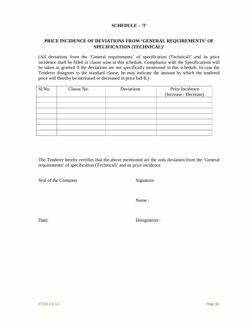
SCHEDULE – ‘I’
DEVIATIONS FROM ‘GENERAL REQUIREMENTS OF SPECIFICATION (TECHNICAL)’
(All deviations from the ‘General Requirements of Specification (Technical)’ shall be filled in clause wise in this schedule. Compliance with the Specifications will be taken as granted if the deviations are not specifically mentioned in this schedule.) Sl No Clause No: Deviations
The Tenderer hereby certifies that the above mentioned are the only deviation from the ‘General Requirements of Specification (Technical)’ Seal of the Company Signature:
Name:
Date: Designation:

ETD8-24/14 Page 29
SCHEDULE – ‘J’
DEVIATIONS FROM ‘GENERAL REQUIREMENTS OF SPECIFICATION (ERECTION)’
(All deviations from the ‘General Requirements of Specification (Erection)’ shall be filled in clause wise in this schedule. Compliance with the Specifications will be taken as granted if the deviations are not specifically mentioned in this schedule.) Sl No Clause No: Deviations
The Tenderer hereby certifies that the above mentioned are the only deviation from the ‘General Requirements of Specification (Erection)’ Seal of the Company Signature:
Name:
Date: Designation:

ETD8-24/14 Page 30
SCHEDULE – ‘K’
DEVIATIONS FROM ‘GENERAL CONDITIONS OF CONTRACT FORM ‘A’ (All deviations from the ‘General conditions of contract FORM ‘A’ shall be filled in clause wise in this schedule. Compliance with the Specifications will be taken as granted if the deviations are not specifically mentioned in this schedule.) Sl No Clause No: Deviations
The Tenderer hereby certifies that the above mentioned are the only deviation from the ‘General conditions of contract FORM ‘A’.
Seal of the Company Signature:
Name:
Date: Designation:

ETD8-24/14 Page 31
SCHEDULE – ‘L’
DEVIATIONS FROM ‘SPECIAL CONDITIONS OF CONTRACT’
(All deviations from the ‘Special conditions of contract’ shall be filled in clause wise in this schedule. Compliance with the Specifications will be taken as granted if the deviations are not specifically mentioned in this schedule.) Sl No Clause No: Deviations
The Tenderer hereby certifies that the above mentioned are the only deviation from the ‘Special conditions of contract ’.
Seal of the Company Signature:
Name:
Date: Designation:

ETD8-24/14 Page 32
SCHEDULE – ‘M’
DEVIATIONS FROM ‘TECHNICAL SPECIFICATION’
(All deviations from the ‘Technical Specification’ shall be filled in clause wise in this schedule. Compliance with the Specifications will be taken as granted if the deviations are not specifically mentioned in this Schedule. ) Sl No Clause No: Deviations
The Tenderer hereby certifies that the above mentioned are the only deviations from the ‘Technical Specification’
Seal of the Company Signatures
Name:
Date Designation:
ETD8-24/14 Page 33
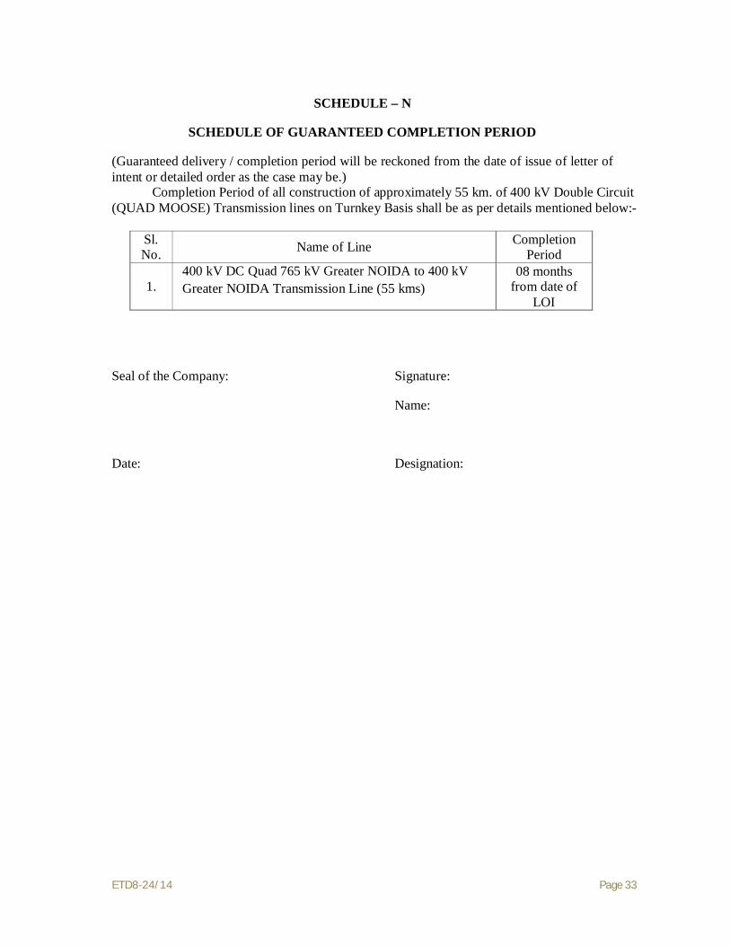
SCHEDULE – N
SCHEDULE OF GUARANTEED COMPLETION PERIOD
(Guaranteed delivery / completion period will be reckoned from the date of issue of letter of intent or detailed order as the case may be.) Completion Period of all construction of approximately 55 km. of 400 kV Double Circuit (QUAD MOOSE) Transmission lines on Turnkey Basis shall be as per details mentioned below:-
Sl. No. Name of Line Completion
Period
1. 400 kV DC Quad 765 kV Greater NOIDA to 400 kV Greater NOIDA Transmission Line (55 kms)
08 months from date of
LOI
Seal of the Company: Signature:
Name:
Date: Designation:

ETD8-24/14 Page 34
TENDERER MUST SUBMIT INCOME TAX AND SALES TAX CLEARANCE CERTIFICATE ALONG WITH THEIR TENDER

ETD8-24/14 Page 35
SCHEDULES TO BE SUBMITTED WITH PRICE BID-II

ETD8-24/14 Page 36
SCHEDULE – ‘G’
PRICE INCIDENCEOF DEVIATIONS FROM ‘INSTRUCTIONS TO TENDERERS’
(All deviations from the ‘Instructions to Tenderers’ shall be filled in clause wise in this schedule. Compliance with the Specifications will be taken as granted if the deviations are not specifically mentioned in this schedule. In case the Tenderer disagrees to the standard clause, he may indicate the amount by which the tendered price will thereby be increased or decreased in price bid-II.) Sl.No. Clause No. Deviations Price
Incidence(Increase/Decrease)
The Tenderer hereby certifies that the above mentioned are the only deviations from the ‘Instructions to Tenderers’ and its Price Incidence.
Seal of the Company Signature:
Name :
Date: Designation :

ETD8-24/14 Page 37
SCHEDULE – ‘H’
PRICE INCIDENCE OF DEVIATIONS FROM ‘GENERAL REQUIREMENTS OF SPECIFICATION (COMMERCIAL)’
(All deviations from the ‘General requirements of specification (Commercial)’ and its price incidence shall be filled in clause wise in this schedule. Compliance with the Specifications will be taken as granted if the deviations are not specifically mentioned in this schedule. In case the Tenderer disagrees to the standard clause, he may indicate the amount by which the tendered price will thereby be increased or decreased in price bid-II.) Sl.No. Clause No. Deviations Price Incidence
(Increase / Decrease) The Tenderer hereby certifies that the above mentioned are the only deviation from the ‘General requirements’ of specification (Commercial)’ and its price incidence
Seal of the Company Signature:
Name :
Date: Designation :
ETD8-24/14 Page 38
SCHEDULE – ‘I’
PRICE INCIDENCE OF DEVIATIONS FROM ‘GENERAL REQUIREMENTS’ OF SPECIFICATION (TECHNICAL)’
(All deviations from the ‘General requirements’ of specification (Technical)’ and its price incidence shall be filled in clause wise in this schedule. Compliance with the Specifications will be taken as granted if the deviations are not specifically mentioned in this schedule. In case the Tenderer disagrees to the standard clause, he may indicate the amount by which the tendered price will thereby be increased or decreased in price bid-II.) Sl.No. Clause No. Deviations Price Incidence
(Increase / Decrease) The Tenderer hereby certifies that the above mentioned are the only deviation from the ‘General requirements’ of specification (Technical)’ and its price incidence
Seal of the Company Signature:
Name :
Date: Designation :

ETD8-24/14 Page 39
SCHEDULE – ‘J’
PRICE INCIDENCE OF DEVIATIONS FROM ‘GENERAL REQUIREMENTS’ OF SPECIFICATION (ERECTION)’
(All deviations from the ‘General requirements’ of specification (Erection)’ and its price incidence shall be filled in clause wise in this schedule. Compliance with the Specifications will be taken as granted if the deviations are not specifically mentioned in this schedule. In case the Tenderer disagrees to the standard clause, he may indicate the amount by which the tendered price will thereby be increased or decreased in price bid-II.) Sl.No. Clause No. Deviations Price Incidence
(Increase / Decrease) The Tenderer hereby certifies that the above mentioned are the only deviation from the ‘General requirements’ of specification (Erection)’ and its price incidence
Seal of the Company Signature:
Name :
Date: Designation :

ETD8-24/14 Page 40
SCHEDULE – ‘K’
PRICE INCIDENCE OFDEVIATIONS FROM ‘GENERAL CONDITIONS OF CONTRACT FORM ‘A’
(All deviations from the ‘General conditions of contract FORM ‘A’ and its price incidence shall be filled in clause wise in this schedule. Compliance with the Specifications will be taken as granted if the deviations are not specifically mentioned in this schedule. In case the Tenderer disagrees to the standard clause, he may indicate the amount by which the tendered price will thereby be increased or decreased in price bid-II.) Sl.No. Clause No. Deviations Price Incidence
(Increase/ Decrease) The Tenderer hereby certifies that the above mentioned are the only deviation from the ‘General conditions of contract FORM ‘A’ and its price incidence
Seal of the Company Signature:
Name :
Date: Designation :

ETD8-24/14 Page 41
SCHEDULE – ‘L’
PRICE INCIDENCE OF DEVIATIONS FROM ‘SPECIAL CONDITIONS OF CONTRACT ’
(All deviations from the ‘Special conditions of contract’ and its price incidence shall be filled in clause wise in this schedule. Compliance with the Specifications will be taken as granted if the deviations are not specifically mentioned in this schedule. In case the Tenderer disagrees to the clause, he may indicate the amount by which the tendered price will thereby be increased or decreased in price bid-II.) Sl.No. Clause No. Deviations Price Incidence
(Increase/ Decrease) The Tenderer hereby certifies that the above mentioned are the only deviation from the ‘Special conditions of contract ’ and its price incidence
Seal of the Company Signature:
Name :
Date: Designation :

ETD8-24/14 Page 42
SCHEDULE – ‘M’
PRICE INCIDENCE OF DEVIATIONS FROM ‘TECHNICAL SPECIFICATION
(All deviations from the ‘Technical Specification and its price incidence shall be filled in clause wise in this schedule. Compliance with the Specifications will be taken as granted if the deviations are not specifically mentioned in this schedule. In case the Tenderer is required to agree to the standard clause, he may indicate the amount by which the tendered price will thereby be increased or decreased.)
Sl.No. Clause No. Deviations Price Incidence
(Increase/ Decrease) The Tenderer hereby certifies that the above mentioned are the only deviation from the ‘Technical Specification’ and its price incidence
Seal of the Company Signatures
Name:
Date: Designation:

PRICE SCHEDULE: A (400 KV DC QUAD Line) SUPPLY OF TOWERS, INSULATORS, HARDWARE FITTINGS AND ACCESSORIES FOR CONDUCTOR & G.S. EARTHWIRE
Bidder's Name & Address: To: Superintending Engineer
Electricity 400&400 kV Transmission Design Circle U.P.Power Transmission Corporation Ltd.
10 th. Floor,ShaktiBhawan 14, Ashok Marg, Lucknow=226001
(Bidder shall quote prices for the following mentioned items. Prices of all accessories, assemblies, components, parts etc. associated with these items are included in bidder's quoted prices for these items).
All values are in Indian Rupees. S N
Item Description
Unit Qty.
Mod
e of
Tra
nsac
tion
(Dir
ect o
r Bo
ught
-out
ite
ms)
Uni
t Ex-
wor
ks p
rice
For direct transaction between bidder and UPPTCL- Excise Duty, Sales Tax and other taxes / Levies (Excluding Octroi and Entry Tax) as applicable shall not be included in the price at Column (6).For bought-out items- Excise Duty, Sales Tax and other Taxes / Levies (Excluding Octroi and Entry Tax )shall invariably be included in the price quoted at Column ( 6 ).
Uni
t Pac
king
& F
orw
ardi
ng C
harg
es
Uni
t Fre
ight
& In
sura
nce
Cha
rges
Unit F.O.R. Destination
price
Total F.O.R.
Destination price
(4x15)
Excise Duty including Ed. Cess if any.
Central Sales Tax / VAT on (6 + 8)
Other Taxes / Levies
(Excluding Octroi and Entry
Tax)
For direct transaction
items (6+8+10+12
+13+14)
Rat
e (%
)
Am
ount
Rat
e (%
)
Am
ount
Rat
e (%
)
Am
ount
For Bought out
items (6+13+14)
1 2 3 4 5 6 7 8 9 10 11 12 13 14 15 16
ETD8-24/14 Page 44
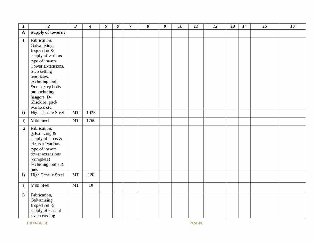
1 2 3 4 5 6 7 8 9 10 11 12 13 14 15 16 A Supply of towers : 1 Fabrication,
Galvanizing, Inspection & supply of various type of towers, Tower Extensions, Stub setting templates, excluding bolts &nuts, step bolts but including hangers, D-Shackles, pack washers etc.
i) High Tensile Steel MT 1925 ii) Mild Steel MT 1760 2 Fabrication,
galvanizing & supply of stubs & cleats of various type of towers, tower extensions (complete) excluding bolts & nuts
i) High Tensile Steel MT 120
ii) Mild Steel MT 10
3 Fabrication, Galvanizing, Inspection & supply of special river crossing

ETD8-24/14 Page 45
towers, Stubs, Stub setting templates, ladders & platforms excluding bolts & nuts, step bolts but including hangers, D-Shackles, pack washers etc.
i) High Tensile Steel MT 175 ii) Mild Steel MT 175 4 Supply of Bolts &
Nuts including step bolts and spring washers
i) Hex. Bolts &
Nuts& spring washer & Step Bolts
MT 150
ii) Hex. Anti Theft
bolts & nuts& spring washer
MT 10
5 (a) Supply of Pipe
type Earthing material per Tower
Nos. 85
(b) Supply of
Counterpoise earthing material including Earthwire per Tower
Nos. 10
6 Supply of following
Tower Accessories
i) Danger Plate Nos. 150

ETD8-24/14 Page 46
ii) Number Plate Nos. 150 iii) Phase Plate (Set of
three) Sets 55
iv) Circuit Plate Nos. 150
v) Anti-Climbing Device
Nos. 150
vi) Bird Guard Nos.
580
B Supply of line materials :
1 Supply of Disc Insulators
i) 120 KN Nos 27500 ii) 160 KN Nos 57750 2 Supply of
Hardware Fittings
i) Double 'I'
Suspension Insulator String (suitable for 2 x 23, 120 KN Disc Insulators)
Sets 580
ii) Single 'I'
Suspension Pilot Insulator String (suitable for 1 x 23, 120 KN Disc Insulators)
Sets 30
iii) Quadruple Tension
Insulator String (suitable for 4 x 23, 160 KN Disc Insulators)
Sets 620

ETD8-24/14 Page 47
iv) Single 'I' Tension Insulator String (suitable for 1 x 24, 120 KN Disc Insulators)
Sets 17
3 Supply of
Accessories for ACSR MOOSE Conductor
i) Mid Span
Compression Joint for ACSR MOOSE conductor
Nos. 900
ii) Repair Sleeve for
ACSR MOOSE conductor
Nos. 275
iii) Quadruple Spacer
Damper for ACSR MOOSE Conductor
Nos. 1100
iv) Quadruple Rigid
Spacer for jumper for ACSR MOOSE Conductor
Nos. 935
4 Supply of
Accessories for 7/3.66 mm G.S. Earthwire
i) Suspension Clamp
for 7/3.66 mm GS Earthwire
Nos. 96
ii) Tension Clamp for
7/3.66 mm GS Earthwire
Nos. 110
ETD8-24/14 Page 48
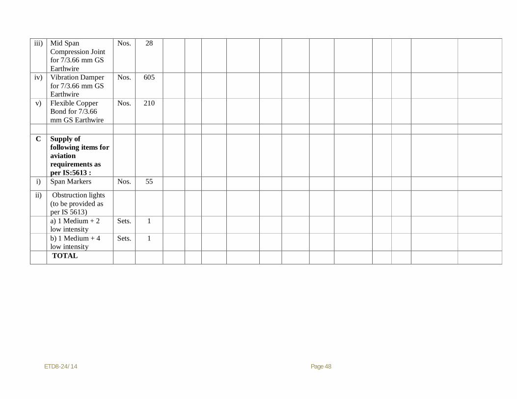
iii) Mid Span Compression Joint for 7/3.66 mm GS Earthwire
Nos. 28
iv) Vibration Damper
for 7/3.66 mm GS Earthwire
Nos. 605
v) Flexible Copper
Bond for 7/3.66 mm GS Earthwire
Nos. 210
C Supply of following items for aviation requirements as per IS:5613 :
i) Span Markers Nos. 55
ii) Obstruction lights
(to be provided as per IS 5613)
a) 1 Medium + 2
low intensity Sets. 1
b) 1 Medium + 4
low intensity Sets. 1
TOTAL

ETD8-24/14 Page 49
PRICE SCHEDULE: B (400 KV DC QUAD Line) CONSTRUCTION OF 400 kV DC QUAD LINE
Bidder's Name & Address: To: Superintending Engineer Electricity 400&400 kV Transmission Design Circle U.P.Power Transmission Corporation Ltd.
10 th. Floor,ShaktiBhawan 14, Ashok Marg, Lucknow=226001
(Bidder shall quote prices for the following mentioned items. Prices of all accessories, assemblies, components, parts etc. associated with these items are included in bidder's quoted prices for these items).
All Values in Indian Rupees SI. No.
Description Unit Quantity
Unit Erection Charges
Total Erection Charges (4x5)
1 2 3 4 5 6 1 Survey i) Survey including preparation of schedule of materials, marking of locations Kms 55
ii) Check survey and final peg marking Kms 55 2 Soil investigation Loc. 14 3 Benching of all kinds of soil (i) Normal Soil Cum 28 (ii) Fissured Rock Cum 14 (iii) Hard Rock Cum 14
4 Cost of excavation of foundation pits including all earth work, backfilling and
leveling etc. for

ETD8-24/14 Page 50
i) Dry Soil Cum 4100 ii) Wet Soil Cum 52200
(iii) Fissured Rock Cum 11000
(iv) Hard Rock Cum 1400
5 Setting of stubs including all foundation work but excluding the cost of concerting and excavation for following towers:(Rates per Location)
i) DA+0, DA+3, DA+6, DA+9 Per Location
92
ii) DB+0, DB+3, DB+6, DB+9 Per Location
29
iii) DC+0, DC+3, DC+6, DC+9 Per Location
14
iv) DD+0, DD+3, DD+6, DD+9 Per Location
6
v) DA+18/ DA+25 Per Location
2
vi) DD+18/ DD+25 Per Location
2
vii) River crossing tower Per Location
2
6 Cost of concreting for all types of foundation including cost of cement, dewatering, forming, shoring and shuttering and curing but excluding cost and installation of reinforcement bars with
i) M20 Concrete Nominal Mix 1:1.5:3 Cum 9500 ii) M10 Lean Concrete Nominal Mix 1:3:6 Cum 1100
7 Installation of steel reinforcement bars in R.C.C. foundation including cost of steel reinforcement bars, cutting, bending, placing, binding etc.
MT 950
8 Protection of Tower Footing
i) Random rubble stone masonry including excavation (1:6 cement mortar) Cum. 110
ii) Revetment of pack 6" & above stone/boulders in heavily coated GI 4mm dia performed wire mesh size 100 mmx100mm.
Cum. 30
iii) M 15 (1:2:4) mixed concrete for top seal cover of revetment Cum. 6

ETD8-24/14 Page 51
iv) Backfilling and gap leveling of volumes enclosed by revetment Cum. 6
9 Erection of super structure of all types of towers and their extensions wherever required including all work above ground level excluding hoisting of insulators, but including fitting of danger number, phase plates, and punching of bolts and also including tack welding etc.
MT 3700
10 Erection of river crossing towers including all work above ground level excluding hoisting of insulators, but including fitting of danger number, phase plates, Ladder and platforms and punching of bolts and also including tack welding etc
MT 200
11 Laying, tension stringing, tensioning, stringing with TSE, clamping, jointing etc complete with quad ‘MOOSE’ ACSR bundle conductor per phase including hoisting of insulators, fitting of all necessary hardware and accessories etc. of conductor for all the three phases
Route Km
55
12 Laying, stringing, tensioning clamping, jointing etc. of ground wires including fitting of all necessary hardware and accessories for :
i) One no. 7/3.66 G.S. Earthwire Route Km
55
ii) One no. Optical Fibre Groundwire Route Km
55
13 Laying, tension stringing, tensioning, stringing with TSE, clamping, jointing etc complete with quad ‘MOOSE’ ACSR bundle conductor per phase and one 7/3.66 mm GS earthwire and one no. OPGW including hoisting of insulators, fitting of all necessary hardware and accessories etc. of conductor for all the three phases for following anchor to anchor spans using river crossing towers.
Lump-Sum
1
14 Grounding work including earth work etc. for pipe type grounding including all material like cost of coke & salt etc.
per Location
85
15 Grounding work for counterpoise grounding per Location
10
16 Installation of Aviation Requirement
a) Painting of Tower above 45m from ground level including cost of materials MT 275
b) Span Marker Sets 55
c) Obstruction lights
a) 1 Medium+2 low intensity Sets 1

ETD8-24/14 Page 52
Date:
(Signature)
Place:
(Printed Name)
Note:
1 In case of discrepancy between unit price and total, the Unit price shall prevail.
(Designation)
2 Octroi, Entry tax, if any, shall be reimbursed at actual at the time of supply for direct transaction as well as for bought out items.
(Common Seal)
3 Any other taxes, duties and levies payable to the contractor, alongwith component of price on which these taxes are payable, shall invariably be indicated in the price schedule for direct transaction items.
a) 1 Medium+4 low intensity Sets 1
TOTAL

ETD8-24/14 Page 53
SCHEDULE – ‘O’-1 (SUPPLY) PRICE SCHEDULE FOR MANUFACTURE, TESTING & SUPPLY OF OPGW AND ITS HARDWARE AND ACCESSORIES
(All prices in Rs.)
S.N. Item Description
Uni
t
Qty
Ex-w
orks
Excise Duty including cess,
if any
Central Sales Tax/VAT
Any other taxes/levies
Pack
ing
&
Forw
ardi
ng
Cha
rges
Tran
spor
tatio
n C
harg
es
Insu
ranc
e C
harg
es
for
Tran
sit &
45da
ys
stor
age t
here
afte
r
F.O
.R. D
estin
atio
n Pr
ices
Total
Rate (%) Amount Rate
(%) Amount Rate (%) Amount
1 2 3 4 5 6 7 8 9 10 11 12 13 14 15 16
1 Fibre Optic Cable & accessories
(i) Supply of 24Fibre (DWSM,G.652D) OPGW fibre optic cable Km. 55
(ii) Supply of Installation Hardware set for 24 Fibre (DWSM) OPGW Fibre Optic cable (excluding joint box)
Set* 55
(iii) Joint Boxes (24–Fiber) No. 20 2 FODP
(i) Supply of FODP 48F : Indoor Type, rack mounted with FCPC coupling and pig tails (DWSM fibre)
No. 04
3 Fibre Optic approach cable
(i) Supply of 24 Fibre (DWSM, G.652D) Km. 04
(ii)
Supply of Installation hardware set including ties/clips/cleats, conduits, ducts, supports, fittings, accessories etc for 24 Fibre (DWSM, G.652D) Fibre Optic Approach Cable
Set 04
TOTAL OPGW SUPPLY Note * One set of installation hardware shall contain all installation hardware fittings as may be required for 1 km of OPGW & fibre optic approach cabling.

ETD8-24/14 Page 54
SCHEDULE – O-2 (Works)
Sl.No. Description of work Unit Quantity Unit Rate Rs.
Total Amount Rs.
1. Supervision during stringing of 24-Fibre OPGW cable Man days 10 2. Splicing & installation of Joint Boxes Nos. 20 3. Installation of Approach Cable Km. 04 4. Installation of FODP No. 04 5. Site testing of Complete Fiber Optic cabling as per the
requirement of Technical Specification Lot. 01
(1) As the above being Bought out item the prices to be quoted shall be inclusive of all Taxes, Duties, License Fee, Import/Custom
Duty etc. as legally applicable as mentioned in clause no. 1.35 of Part-II “Special Conditions Of Contract”
Date:
Signatures:
Seal of the Company
Name:
Designation :

ETD8-24/14 Page 55
SECTION – 2
GENERAL REQUIREMENTS OF SPECIFICATION (COMMERCIAL)
2.1 Scope
2.1.1 This specification provides for design, manufacture, testing, supply and delivery FOR destination railway station/stores of plants/ equipment and/ or erection of transmission lines in Uttar Pradesh. The description of equipment, their quantities and quantum of work to be executed are detailed in Special Conditions of Contract and technical specification and relevant schedules given in Part – II and Part – III respectively.
2.1.2 Equipments shall be offered complete with parts and accessories that are necessary or usual for their efficient operation. Such parts shall be deemed to be within contractor’s scope whether specifically mentioned or not.
2.1.3 The General Conditions of Contract Form –A, copy of which is attached hereto, form an integral part of this specification. The contractor shall supply all materials / equipments and perform all works in strict accordance of the provisions of the said Form ‘A’.
2.2 Climatic and Isoceraunic Conditions
2.2.1 Equipments to be supplied against this specification are to be installed on the transmission lines passing through an area where the climatic and isoceraunic conditions are as given below:
(i) Annual rain fall (max) : 120 cm (ii) Maximum ambient temp.
a. In shade : 47.50C b. In Sun : 65.50C
(iii) Minimum ambient temp. : 00C (iv) Relative humidity : 100% (max.) : 10% (min.) (v) Number of monsoon months : 4 (June to Sept.)
(vi) Isoceraunic level : 50
2.2.2 The equipments offered shall be suitable for satisfactory operation under the above conditions in tropical climate and shall be able to withstand a wide range of temperature variation experienced in Uttar Pradesh.
2.3 Deviation from specification 2.3.1 Tenderers are requested to accept all the provisions of this specification and all the clauses
of Form ‘A’ to facilitate early finalization of the contract. Should the tenderer, however, desire to depart in any respect from the provisions of this specification including the provisions of Form A, either on account of manufacturing practice or any other reason, he must specifically mention the same in his tender under the schedule heading “Deviations from the General Conditions of Contract Form A and Specification”.

ETD8-24/14 Page 56
2.4 Security Deposit 2.4.1 The successful tenderer shall have to deposit Security Deposit as required under clause 3
of enclosed General Conditions of the Contract Form ‘A’ for an amount not less than 1% of the total value of the contract.
2.5 Performance Guarantee 2.5.1 The successful tenderer shall have to furnish a performance bank guarantee for 10% value
of the contract for correct quality and satisfactory performance of the works covered under this specification. This bank guarantee shall be valid for a period of 12 months from the actual date of commissioning of equipment or 18 months from the date of receipt of entire supply of equipments, whichever is earlier. Any defect in the equipment or the workmanship noticed in this period shall be rectified to the entire satisfaction of the purchaser and if necessary the equipments replaced free of cost as the case may be.
2.6. Warranty The successful tenderer shall have to furnish a warranty from the manufacturer to the
satisfaction of the purchaser whereby the equipment supplied by him will be guaranteed for 18 months from date of completion of entire supply or 12 months from the date of their being put into service whichever is earlier, against all manufacturing defects and in the event of any defect in the material or workmanship coming to notice, the equipment shall be replaced free of charge at site or the defects shall be removed to the entire satisfaction of the Purchaser free of cost as the case may be.
2.7 Raw materials
2.7.1 The tenderers should clearly indicate the position of availability of raw materials with him for the manufacture of materials/ equipments offered by him. The tenderer shall himself be responsible for timely arrangement / procurement of all raw materials required for the manufacture of all tendered items. However, depending on the policy of the Govt. of India, Purchaser, may assist to the extent possible for arrangement of such raw material through Central Electricity Authority, DGTD or other such agencies but without any financial liability to the Purchaser or effecting / linking the delivery of the equipments with the availability of raw materials against such assistance /recommendations.
2.8 Delivery Schedule 2.8.1 The time and the date of completion of the works as stipulated in the Special Conditions
of Contract (Part –II,) and accepted by the tenderer shall be deemed to be the essence of the Contract. The contractor shall so organise his resources and perform his work as to complete it not later than the date agreed to. The time for completion of the works contracted for, shall be reckoned from the date of acceptance of Letter of Intent by the Contractor.
2.8.2 The contractor shall submit a detailed PERT network within the time frame agreed above consisting of adequate number of activities covering various key phases of the works such as design, procurement, manufacturing, shipment and/ or field erection activities within fifteen (15) days after the date of acceptance of notice of Award of Contract. This net-work shall also indicate the inter-phase facilities to be provided by the Purchaser and the dates by which such facilities are needed. Contractor shall discuss the network so submitted with the Purchaser and the agreed network which may be in the form as submitted or in revised form in line with the outcome of discussion shall form part of the

ETD8-24/14 Page 57
Contract to be signed within thirty (30) days from the date of Notice of Award of Contract.
2.8.3 The above PERT network shall be reviewed and periodic review reports shall be submitted by the Contractor as directed by the Purchaser.
2.9 Price Reduction Clause 2.9.1 If the Contractor fails in the due performance of his contract, the damages for delay shall
become payable by the contractor as per clause 32 of General Conditions of Contract Form ‘A’
2.10 Terms of Payment
2.10.1 The terms of payment shall be as per Clause 25 of Form ‘A’.
2.11. Insurance
2.11.1 The Contractor shall arrange, secure and maintain insurance as may be necessary and for all such amounts to protect his interests and the interests of the Purchaser, against all risks as detailed herein. The Contractor’s failure in this regard shall not relieve him of any of his contractual responsibilities and obligations.
2.11.2 Any loss or damage to the equipment during handling, transporting, storage and erection, till such time the plant is taken over by Purchaser shall be to the account of the Contractor . The Contractor shall be responsible for preferring of all claims and make good for the damage or loss by way of repairs and / or replacement of the portion of the works damaged or lost. The transfer of title shall not in any way relieve the Contractor of the above responsibilities during the period of the contract. The Contractor shall provide the Supervising Engineer with a copy of all insurance policies and documents taken out by him in pursuance of the Contract. Such copies of documents shall be submitted to the purchaser immediately after such insurance coverage. The contractor shall also inform the purchaser in writing at least sixty (60) days in advance, regarding the expiry, cancellation and / or change in any of such documents and ensure revalidation/ renewal etc. as may be necessary, well in time.
2.11.3 All costs on account of insurance liabilities covered under the Contract will be on Contractor’s account and will be included in Contract price. However, the purchaser may from time to time during the pendency of the Contract, ask the Contractor in writing to limit the insurance coverage risks and in such a case, the parties to the Contract will agree for a mutual settlement, in reduction in Contract price to the extent of reduced premium amounts.
2.11.4 The contractor shall cover insurance, with Indian Insurance Companies only.
2.11.5 This specification covers the insurance requirements for the portion of the works to be performed at the field.
2.12 Responsibility of the Contractor
2.12.1 He shall guarantee and be responsible for the quality and workmanship of all materials and completed works, correct designs and drawings and their accuracy, conformity of all works to the approved designs and drawings, testing of equipments and their correct delivery and / or their erection within the guaranteed completion period.

ETD8-24/14 Page 58
2.12.2 The purchaser shall have the right to require the contractor to make anychange in the design which may be necessary in the opinion of the Engineer, to make the equipment and work conform to the provisions and contents of specifications, without extra cost to purchaser. Approval by the Engineer, or by the representative of the Purchaser, of the contractor’s or sub-contractor’s drawings, designs, materials or of other parts of work involved in the contract, or of the tests carried out either by the contractor or purchaser, shall not relieve the Contractor of any part of the contractor’s obligations of meeting all the requirements of the specifications or of the responsibility for the correctness of the contractor’s designs and drawings. Any manufacture or other work performed prior to the approval of drawings and tests will be at contractor’s risk.
2.12.3 The contractor shall guarantee and be responsible for the design, fabrication, galvanising and testing, packing, insurance during transit, despatch of all materials to destination railways stations/stores, proper handling , cartage and storage of all line materials at site in their custody, line erection, setting to work and maintenance of the said transmission lines.
2.13 Quantity
2.13.1 The quantities mentioned in this specification are subject to increase or decrease as per actual requirement of the purchaser at the unit prices mentioned in price schedule. This increase or decrease shall not be more than 50%.
2.14 Progress Report
2.14.1 Fortnightly reports showing the actual progress made in the receipt of materials/ equipments by the contractor and completion of various works shall be regularly submitted to the purchaser, starting two (2) months from the date of Letter Of Intent or date of contract/ purchase order.
2.15 Training of Purchaser’s Staff
2.15.1 The purchaser reserves the right to attach its own staff comprising of engineers & subordinates in the contractor’s works or with the erection staff for the purpose of gaining experience. Contractor shall extend all necessary facilities for this purpose. However the contractor shall not incur any expenditure on this account.

ETD8-24/14 Page 59
SECTION –3
GENERAL REQUIREMENTS OF SPECIFICATION (TECHNICAL)
3.1 General
3.1.1 This part covers technical conditions pursuant to the contract and will form an integral part of the Contract. The following provisions shall supplement all the detailed technical specifications and requirements brought out in the accompanying technical specifications (Part III). The Contractor’s proposal shall be based on the use of equipment and material complying fully with the requirement, specified herein. It is recognized that Contractor may have standardised on the use of certain components, materials, processes or procedures different than those specified herein. Alternate proposals offering similar equipment based on the manufacturer’s standard practice will also be considered, provided such proposals meet the specified design, standards and performance requirement and are acceptable to the Purchaser.
3.2 Limit of Contract 3.2.1 Equipment furnished shall be complete in every respect with all mountings, fittings,
fixtures and standard accessories normally provided with such equipments and/or needed for erection, completion and safe operation of the equipments as required by applicable codes though they may not have been specifically detailed in the technical specifications, unless included in the list of exclusions. All similar standard components/ parts of similar standard equipment provided shall be inter-changeable with one another.
3.3 Engineering Data
3.3.1 The furnishing of engineering data by the Contractor shall be in accordance with the schedule as specified in the technical specifications. The review of these data by the Engineer will cover only general conformance of the data to the specifications and documents, and of the dimensions which might affect plant layout. This review by the Engineer may not indicate a thorough review of all dimensions, quantities, and details of the equipments, materials, any devices or items indicated or the accuracy of the information submitted. This review and/ or approval by the Engineer shall not be construed by contactor, as limiting any of his responsibilities and liabilities for mistakes and deviations from the requirements, specified under these specifications and documents.
3.3.2 All Engineering data submitted by the Contractor after final process including review and approval by the Engineer shall form part of the Contract Documents and the entire works covered under these specifications shall be performed in strict conformity, unless otherwise expressly requested by the Engineer in writing.
3.4 Drawings 3.4.1 All drawings submitted by the Contractor including those submitted at the time of
tender shall be in sufficient detail to indicate the type, size, weight of each component, or any other information specifically requested in the specifications.
3.4.2 Each drawing submitted by the Contractor shall be clearly marked with the name of the purchaser, the unit designation, the specification’s title, the specification

ETD8-24/14 Page 60
number and the name of the Project. All titles, noting, markings and writings on the drawing shall be in English. All the dimensions should be in metric unit.
3.4.3 The drawings submitted by the Contractor shall be reviewed by the Engineer as far as practicable within the time schedule as mutually agreed and shall be modified by the Contractor if any modifications and /or corrections are required by the Engineer. The Contractor shall incorporate such modifications and/ or corrections and submit the final drawings for approval. Any delays arising out of failure by Contractor to rectify the drawings in good time shall not alter the contract completion date.
3.4.4 The drawing sent for approval to the Engineer shall be in triplicate. One print of such drawings will be returned to the Contractor, by the Engineer marked ‘approved’. After approval of such drawings the Contractor shall thereupon furnish the Owner with required number of prints and one reproducible original of the drawings after incorporating all corrections.
3.4.5 Further work by the Contractor shall be in strict accordance with these drawings and no deviation shall be permitted without the written approval of the Engineer, if so required.
3.4.6 All manufacturing and fabrication work in connection with the equipment prior to the approval of the drawings shall be at Contractor’s risk. The Contractor may make any change in the design which are necessary to make the equipments conform to provisions and intent of the Contract and such of work by changes will again be subject to approval by Engineer. Approval of Contractor’s drawings by the Engineer shall not relieve the Contractor of any of his responsibilities and liabilities under Contract.
3.5 Manufacturing Schedule 3.5.1 The Contractor shall submit to the Engineer his manufacture and delivery schedules
for all equipment within thirty (30) days from the date of the Letter of Intent. Such schedules shall be in line with the detailed net-work for all phases of the work of the Contractor. Such schedules shall be revised, updated and submitted to the Engineer, once every two (2) months thereafter by the Contractor. Schedules shall also include the materials and equipments purchased from outside supplier.
3.6 Reference Standards
3.6.1 The codes and / or standards referred to in these specifications shall govern, in all the cases wherever such references are made. In case of a conflict between such codes and / or standards and the specifications the latter shall govern. Such codes and / or standards referred to shall mean the latest revisions, amendments/ changes adopted and published by relevant agencies. In case of any further conflict in this matter, the same shall be referred to the Engineer, whose decision shall be final and binding.
3.6.2 Other internationally acceptable standards which ensure equal or higher performance than those specified shall also be accepted.

ETD8-24/14 Page 61
3.7 Design Improvements
3.7.1 The Engineer or the Contractor may propose changes in the specification of the equipments or quality thereof and if the parties agree upon any such changes, the specification shall be modified accordingly.
3.7.2 If any such agreed upon change is such that it affects the price and schedule of completion, the parties shall agree in writing as to the extent of any change in the price and / or schedule of completion before the Contractor proceeds with the change. Following such arrangement, the provision thereof shall be deemed to have been amended accordingly.
3.8 Quality Assurance
3.8.1 Quality Assurance Programme To ensure that the equipments and services under the scope of this contract whether manufactured or performed within the contractor’s works or at his Sub-Contractor’s Premises or at the Purchaser’s site or at any other place of work are in accordance with specifications. The Contractor shall adopt suitable Quality Assurance Programme (QAP) to control such activities at all points necessary. Such programme shall be outlined by the Contractor and shall be finally accepted by the Engineer after discussions before the award of contract. The Quality Assurance Programme of the Contractor shall generally cover the following:
(a) His organisational structure for the management and implementation of the proposed quality Assurance Programme.
(b) Documentation control System.
(c) Qualification data for tenderers’ key personnel.
(d) The procedure for purchase of materials, parts, components and selection of Sub-Contractor’s services including vendor analysis, source inspection, incoming raw-material inspection, verification of materials purchased etc.
(e) System for shop manufacturing and site erection controls including process controls and fabrication and assembly controls.
(f) Control of non-conforming items and system for corrective actions.
(g) Inspection and test procedure both for manufacture and field activities.
(h) Control of calibration and testing of measuring and testing equipments.
(i) System for indication and appraisal of inspection status.
(j) System for quality audits.
(k) System for authorising release of manufactured product to the purchaser.
(l) System for maintenance of records.

ETD8-24/14 Page 62
(m) System for handling storage and delivery and
(n) A quality plan detailing out the specific quality control procedure adopted for controlling the quality characteristics relevant to each item of equipment furnished.
3.8.2 Quality Assurance Documents:
The Contractor shall be required to submit the following Quality Assurance documents within three weeks after award of the contracts.
(i) Material test reports on components as specified by the specifications.
(ii) The inspection plan with verification, inspection plan check points, verification sketches if used and methods used to verify that the inspection and testing points in the inspection plan were performed satisfactorily.
(iii) Factory test results for testing required as per applicable codes and standards referred in the specification.
3.9 Engineer’s Supervision
3.9.1 To eliminate delays and avoid disputes and litigation, it is agreed between the parties to the contract that all matters and questions shall be referred to the Engineer and his decision shall be final.
3.9.2 The work shall be performed under the directions and supervision of the Engineer. The scope of duties of the Engineer, pursuant to the Contract, will include but not limited to the following: -
a. Interpretation of all the terms and conditions of these documents and specifications.
b. Review and interpretation of all the Contractor’s drawings, Engineering data etc.
c. Witness or authorise his representative to witness tests and trials either at the manufacturer works or at site, or at any place where work is performed under Contract.
d. Inspect, accept or reject any equipment, material and work under the Contract.
e. Issue certificate of acceptance and / or progressive payment and final payment certificates.
f. Review and suggest modifications and improvements in completion schedules from time to time and
g. Supervise the quality assurance programme implementation at all stages of the works.

ETD8-24/14 Page 63
3.10 Inspection, Testing & Inspection Certificate
3.10.1 The Engineer, his duly authorised representative and / or an outside inspection agency acting on behalf of the purchaser shall have at all reasonable times access to the Contractor’s premises or works and shall have the power, at all reasonable times to inspect and examine the materials and workmanship of the works during its manufacture or erection and if part of the works is being manufactured or assembled on other premises or works, the Contractor shall obtain for the Engineer and for his duly authorised representative permission to inspect as if the Works were manufactured or assembled on the contractor’s own premises or works.
3.10.2 The inspection call shall be given by contractor when the goods have actually become ready in all respects in the works of the manufacturer and not on the basis of anticipated date of completion. A period of 4 weeks of 6 weeks shall be allowed for UPPTCL for making travel arrangement for their inspecting officer to reach their works. This period of 4 or 6 weeks, will be from the date of inspection call is received by UPPTCL. The period of 4 weeks shall be for works situated in U.P., Union Territory of Delhi, Rajasthan, Bihar and West Bengal and 6 weeks for all the remaining Sates. In case the goods are not available for inspection at the time of the arrival of the inspecting officer (s) the firm shall pay to UPPTCL a sum of Rs. 1000/- (Rs. one thousand only) per day from the date of departure to the date of arrival (both included) of the engineer concerned.
3.10.3 The Engineer or Inspector shall within fifteen (15) days from the date of inspections as defined herein give notice in writing to the contractor of any objection to any drawings and all or any equipment and workmanship which in his opinion is not in accordance with the Contract. The contractor shall give due consideration to such objections and shall either make the modifications that may be necessary to meet the said objections or shall confirm in writing to the Engineer / Inspector giving reasons therein, that no modifications are necessary to comply with the Contract.
3.10.4 When the factory tests have been completed at the Contractor’s or Sub-Contractor’s works, the Engineer / Inspector shall issue a certificate to this effect within fifteen (15 ) days after completion of tests but if the tests are not witnessed by the Engineer / Inspector, the certificate shall be issued within fifteen (15) days of receipt of the Contractor’s Test certificate by the Engineer / Inspector. The completion of these tests or the issue of the certificate shall not bind the owner to accept the equipment should it, on further tests after erection be found not to comply with the Contract.
3.10.5 In all cases where the Contract provides for the tests whether at the premises or Works of the Contractor or of any Sub-Contractor, the Contractor, except where otherwise specified, shall provide free of charge such items as labour, materials, electricity, fuel, water, stores, apparatus and instruments as may be reasonably demanded by the Engineer / Inspector or his authorised representative to carry out effectively, such test of the equipment in accordance with the Contract and shall give

ETD8-24/14 Page 64
facilities to the Engineer / Inspector or to his authorised representative in the accomplishing testing.
3.10.6 The inspection by Engineer and issue of Inspection certificate thereon shall in no way limit the liabilities and responsibilities of the Contractor in respect of the agreed Quality Assurance Programme forming a part of the Contract.
3.10.7 After successful inspection and tests, the purchaser shall issue a material despatch clearance certificate authorising the contractor to despatch the inspected/ tested material. No material shall be despatched without issue of despatch clearance certificate from the Purchaser. In case inspection/ tests have been waived off by the Purchaser even then contractor shall not despatch the material without issue of despatch clearance certificate.
3.11 Test
3.11.1 Performance and Guarantee Test 3.11.1.1 The final test as to the performance and guarantees shall be conducted at Site, by
the purchaser. The Contractor’s Commissioning and Start-up Engineers shall make the equipment ready for such tests and assist the owner in conducting such tests free of cost.
3.11.1.2 These tests shall be binding on both the parties of the Contract to determine compliance of the equipment with the performance guarantee.
3.11.1.3 Any special equipment, tools and tackles required for the successful completion of the performance and Guarantee Test shall be provided by the Contractor, free of cost.
3.11.1.4 The guaranteed performance data of the equipment shall be proved by the Contractor during these performance and guarantee tests. Should the results of these test show any decrease from the guaranteed values, the Contractor shall modify the equipment as required to enable it to meet the guarantees. In such case, Performance and Guarantee Test shall be repeated within one month from the date of equipment is ready for re-test and all cost for modifications including labour, materials and the cost of additional testing to prove that the equipment meets the guarantee, shall be borne by the Contractor.
3.11.1.5 The specific tests to be conducted on equipments have been brought out in the technical specification.
3.12 Packing 3.12.1 All the equipments shall be suitably protected, coated, covered or boxed and crated to
prevent damage or deterioration during transit, handling and storage at site till the time of erection. While packing all the materials, the limitations from the point of view of availability of railways wagon sizes in India should be taken into account. The contractor shall be responsible for any loss or damage during transportation, handling and storage due to improper packing. The details furnished are for the guidance of tenderers. Purchaser takes no responsibility of the availability of the wagon and variations in dimensions.

ETD8-24/14 Page 65
3.13 Design Co-ordination 3.13.1 The Contractor shall be responsible for the selection and design of appropriate
equipment to provide the best co-ordinated performance of the entire system. The basic design requirements are detailed out in Technical Specifications. The design of various components, sub- assemblies and assemblies shall be so done, so that it facilitates easy field assembly and maintenance.
3.14 Design Co-ordination Meeting
3.14.1 The Contractor will be called upon to attend design co-ordination meetings, with the Engineer , other Contractors and the Consultants of the purchaser, if any, during the period of Contract. The Contractor shall attend such meetings at his own cost at Lucknow on at mutually agreed venues as and when required and fully co-operate with such persons and agencies involved during those discussions.
3.15 Taking Over
3.15.1 Upon successful completion of all the tests on equipments furnished and erected by the Contractor, the Engineer shall issue to the Contractor a taking over certificate as a proof of the final acceptance of the equipment . Such certificate shall not unreasonably be with-held nor will the Engineer delay the issuance thereof, on account of minor omissions or defects which do not affect the commercial operation and / or cause any serious risk to the equipments. Such certificate shall not relieve the contractor of any of his obligations which otherwise survive, by the terms and conditions of the contract after issuance of such certificate.

ETD8-24/14 Page 66
SECTION – 4
GENERAL REQUIREMENTS OF SPECIFICATION (ERECTION)
4.1 General
4.1.1 The following shall supplement the conditions already contained in the other parts of these specifications and documents and shall govern that portion of the work of this Contract which is to be performed at Site.
4.1.2 The contractor upon award of the Contract shall, in addition to a Project Co-ordinator, nominate another responsible officer as his representative at Site suitably designated for the purposes of overall responsibility and co-ordination of the works to be performed at Site. Such person shall function from the Site office of the Contractor during the pendency of the Contract.
4.2 Regulation of Local Authorities and Statues
4.2.1 The Contractor shall comply with all the rules and regulations of local authorities during the performance of his field activities.
4.2.2 All registration and statutory inspection fees, if any, in respect of this work pursuant to this Contract shall be to the account of the Contractor.
4.3 Owner’s Lien on Equipments
4.3.1 The Purchaser shall have lien on all equipments including those of the Contractor brought to the Site for the purposes of erection, testing and commissioning of the plant. The Purchaser shall continue to hold the lien on all such equipments throughout the period of Contract. No material brought to the Site shall be removed from the Site by the Contractor and / or his Sub –Contractors without the prior written approval of the Engineer.
4.4 Inspection, Testing and Inspection Certificate
4.4.1 The provisions of the clause entitled “Inspection, Testing and Inspection Certificates” under section – 3 shall also be applicable to the erection portion of the works. The Engineer shall have the right to re-inspect any equipment though previously inspected and approved by him, at the Contractor’s works, before and after the same are erected at site, if by the above inspection, the Engineer rejects any equipment, the contractor shall make good for such rejections either by replacement or modifications /repairs as may be necessary, to the satisfaction of the Engineer. Such replacements will also include the replacements or re-execution of such of those works of other Contractors and / or agencies, which might have got damaged or affected by the replacements or re-works done to the Contractor’s work.

ETD8-24/14 Page 67
4.5 Contractor’s Site Office Establishment
4.5.1 The Contractor’s shall establish a Site Office at the Site and keep posted an authorised representative for the purpose of the Contract. Any written order or instruction of the Engineer or his duly authorised representative, shall be communicated to the said authorised representative of Contractor at the Site Office and the same shall be deemed to have been communicated to the Contractor at his legal address.
4.6 Discipline of Workmen
4.6.1 The Contractor shall adhere to the disciplinary procedure set by the Engineer in respect of his employees and workmen at site. The Engineer shall be at liberty to object to the presence of any representative or employee of the Contractor at the site if in the opinion of the Engineer such employee has mis-conducted himself or be incompetent or negligent or otherwise undesirable and then the Contractor shall remove such a person objected to and provide, in his place, a competent replacement.
4.7 Contractor’s Field Operation
4.7.1 The Contractor shall keep the Engineer informed in advance regarding his field activities / plans and schedules for carrying out each part of the works. Any review of such plan or schedule or method or work by the Engineer shall not relieve the contractor or any of his responsibilities towards the field activities. Such reviews shall also not be considered as an assumption of any risk or liability by the Engineer or the Purchaser or any of his representatives and no claim of the Contractor will be entertained because of the failure or inefficiency of any such plan or schedule or method of work reviewed. The Contractor shall be solely responsible for the safety, adequacy and efficiency of plant and equipment and his erection methods.
4.7.2 The Contractor shall have the complete responsibility for the conditions of the Work-site including the safety of all persons employed by him or his sub-contractor and all the properties under his custody during the performance of work.. This requirement shall apply continuously till the completion of the Contract and shall not be limited to normal working hours. The construction review by the Engineer is not intended to include review of Contractor’s safety measures in, on or near the Work –Site and their adequacy or otherwise.
4.8. Progress Report
4.8.1 Contractor shall submit the fortnightly progress report detailing out the progress achieved on all erection activities as compared to the schedules. The report shall also indicate the reasons for the variance between the scheduled and actual progress and the action proposed for corrective measures wherever necessary.

ETD8-24/14 Page 68
4.9 Time – The Essence of Contract
4.9.1 The time and date of completion of the works as stipulated in the Contractor’s proposal and accepted by the Purchaser shall be deemed to be essence of the Contract. The Contractor shall so organize his resources and perform his work as to complete it not later than the date agreed to. The time for completion of the works contracted for, shall be reckoned from the date of acceptance of the Letter of Intent by the Contractor.
4.9.2 The Contractor shall submit a detailed PERT network within the time frame agreed above consisting of adequate number of activities covering various key phases of the works such as design, procurement, manufacturing, despatch and field erection activities within fifteen (15) days after the date of acceptance of notice of award of contract. This network shall also indicate the inter-phase facilities to be provided by the Purchaser and the dates by which such facilities are needed. Contractor shall discuss the network so submitted with the Purchaser and the agreed network, which may be in the form as submitted or in revised form in line with the outcome of discussions, shall form part of the Contract to be signed within thirty (30) days from the date of Notice of Award of Contract. During the performance of the Contract, if in the opinion of the Engineer proper progress is not maintained, suitable changes shall be made in the Contractor’s operations to ensure proper progress.
4.9.3 The above PERT network shall be reviewed and periodic review reports shall be submitted by the Contractor as directed by the Engineer.
4.10 Protection of work
4.10.1 The Contractor shall have total responsibility for protecting his works till it is finally taken over by the Engineer. No claim will be entertained by purchaser or the Engineer for any damage or loss to the Contractor’s works and the Contractor shall be responsible for the complete restoration of the damaged works to its original conditions to comply with the specifications and drawings. Should any such damage to the Contractor’s works occur because of the other party not under his supervision or control, the Contractor shall make his claim directly with the party concerned . If disagreement or conflict or dispute develops between the Contractor and the other party or parties concerned regarding the responsibly for damage to the Contractor’s works the same shall be resolved amicably by the Contractor. The Contractor shall not cause any delay in repair of such damage works because of any delay in the resolution of such disputes. The Contractor shall proceed to repair the work immediately and no cause thereof will be assigned pending resolution of such dispute.
4.11 Security
4.11.1 The Contractor shall have total responsibility for all equipments and materials in his custody stored, loose, semi-assembled and / or erected by him at Site. The Contractor
ETD8-24/14 Page 69
shall make suitable security arrangements including employment of security personnel to ensure the protection of all materials, equipment and Works from theft, fire, pilferage and any other damage and loss. All materials of the contractor shall enter and leave the project Site only with the written permission of the Engineer in the prescribed manner.
4.12 Materials Handling and Storage
4.12.1 All the equipment furnished under the contract and arriving at Site shall be promptly received, unloaded and transported and stored in the storage spaces by the Contractor.
4.12.2 Contractor shall be responsible for examining all the shipment and notify the Engineer immediately of any damage, shortage, discrepancy etc. for the purpose of Engineer’s information only. The Contractor shall submit to the Engineer every fortnight a report detailing all the receipts during the fortnight. However, the contractor shall be solely responsible for any shortages or damage in transit, handling and or in storage and erection of the equipment at the Site. Any demurrage, wharfage and other such charges claimed by the transporters, railways etc shall be to the account of the contractor.
4.12.3 Contractor shall maintain an accurate and exhaustive record detailing out the list of all equipments received by him for the purpose of erection and keep such record open for the inspection of the Engineer at any time.
4.12.4 All equipment shall be handled very carefully to prevent any damage or loss. No bare wire ropes, slings etc. shall be used for unloading and/ or handling of the equipment without the specific written permission of the Engineer. The equipments stored shall be properly protected to prevent damage either to the equipment or the floor where they are stored. The equipment from the store shall be moved to the actual location at the appropriate time so as to avoid damage of such equipment at site.
4.12.5 The Contractor shall ensure that the packing materials and protection devices used for the various equipment during transit and storage are removed before the equipments are installed.
4.12.6 The consumables and other supplies likely to deteriorate due to storage must be thoroughly protected and stored in a suitable manner to prevent damage or deterioration in quality by storage.
4.12.7 All the materials stored in the open or dusty locations must be covered with suitable weather proof and flame proof covering material wherever applicable.
4.12.8 If the materials belonging to the Contractor are stored in areas other than those earmarked for him, the Engineer will have the right to get it moved to the area earmarked for the Contractor at the Contractor’s cost.

ETD8-24/14 Page 70
4.13 Field Office Records
4.13.1 The Contractor shall maintain at his Site –Office up-to-date copies of all drawings, specification and other contract documents and any other supplementary data complete with all the latest revisions thereto. The Contractor shall also maintain in addition the continuous record of all changes to above Contract Documents, drawings, specifications, supplementary data etc. effected at the field and on completion of his total assignment under the contract shall incorporate all such changes on the drawings and other engineering data to indicate as installed conditions of the equipments furnished and erected under the Contract. Such drawings and engineering data shall be submitted to the Engineer in required number of copies.
4.14 Contractor’s Materials Brought on to site
4.14.1 The Contractor shall bring to Site all equipments, components, parts, materials including construction equipment , tools and tackles for the purpose of the works under intimation to the Engineer. All such goods shall not on any account be removed or taken away the Contractor without the written permission of the Engineer. The Contractor shall nevertheless be solely liable and responsible for any loss or destruction thereof and damage thereto.
4.14.2 The purchaser shall have a lien on such goods for any sum or sums which may at any time be due or owing to him by the Contractor under, in respect of or by reasons of the Contract. After giving a fifteen ( 15) days notice in writing of his intention to do so, the Purchaser shall be at liberty to sell and dispose of any such goods, in such manner as he shall think fit including public auction towards the satisfaction of such sum or sums due as aforesaid.
4.14.3 After completion of the works, the Contractor shall remove from the Site under the direction of the Engineer the materials such as construction equipment, erection tools and tackles, scaffolding etc. with the written permission of the Engineer. If the Contractor fails to remove such materials within fifteen ( 15 ) days of issue of a notice by the Engineer to do so then the Engineer shall have the liberty to dispose off such materials as detailed under clause 4.14.2 above and credit the proceeds thereto to the account of the contractor.
4.15 Protection of Property and Contractor’s Liability
4.15.1 The contractor shall be responsible for any damage resulting from his operations. He shall also be responsible for protection of all persons including members of public and employees of the Purchaser and the employees of other Contractors and Sub-contractors and all public and private property including structures, building , other plants and equipments and utilities either above or below the ground.
4.15.2 The Contractor will ensure provision of necessary safety equipments such as barriers, sign boards, warning lights, and alarms etc. to provide adequate protection to persons

ETD8-24/14 Page 71
and property. The Contractor shall be responsible to give reasonable notice to the Engineer and owner of public or private property and utilities when such property and utilities are likely to get damaged or injured during the performance of his works and shall make all necessary arrangements with such owner related to removal and / or replacement or protection of such property and utilities.
4.16 Unfavourable Working Conditions
4.16.1 The contractor shall confine all his field operations to those works which can be performed without subjecting the equipment and materials to adverse effects, during inclement weather conditions like monsoon, storms etc. and during other unfavourable construction conditions. No field activities shall be performed by the Contractor under conditions which might adversely affect the quality and efficiency thereof, unless special precautions or measures are taken by the Contractor in a proper and satisfactory manner in the performance of such works and with the concurrence of the Engineer. Such unfavourable construction conditions will in no way relieve the contractor of his responsibility to perform the works as per the schedule.
4.17 Force Majeure
4.17.1 Force majeure is herein defined as any cause which is beyond the control of the Contractor or the Purchaser as the case may be, which they could not foresee or with a reasonable amount of diligence could not have foreseen and which substantially affect the performance of the Contract, such as
a. natural phenomena including but not limited to floods, droughts, earthquakes and epidemics.
b. acts of any Government, domestic or foreign, including but not limited to war, declared or undeclared , priorities, quarantines embargoes.
provided either party shall within fifteen ( 15) days from the occurrence of such a cause notify the other in writing of such causes.
4.17.2 The Contractor or the Purchaser shall not be liable for delays in performing his obligations resulting from any forces majeure cause as referred to and / or defined above. The date of completion will, subject to hereinafter provided, be extended by a reasonable time.
4.18 Protection of Monuments and Reference Point
4.18.1 The Contractor shall ensure that any finds such as relic , antiquity , coins, fossils, etc, which he may come across during the course of performance of his works either during excavations or elsewhere, are properly protected and handed over to the Engineer. Similarly the Contractor shall ensure that the bench marks, reference points etc. which are marked out either with the help of Engineer or by the Engineer shall
ETD8-24/14 Page 72
not be disturbed in any way during the performance of his works. If any work is to be performed which may disturb such references, the same shall be done only after these are transferred to other suitable locations under the direction of the Engineer. The Contractor shall provide all necessary materials and assistance for such relocation of reference points etc.
4.19 Work & Safety Regulations
4.19.1 The Contractor shall ensure the safety of all the workmen, materials and equipment either belonging to him or to others working at Site.
4.19.2 The Contractor will notify the Engineer of his intention to bring on to Site any equipment or any container, with liquid or gaseous fuel or other substance which may create hazard. The Engineer shall have the right to prescribe the conditions under which such equipment or container may be handled and used, during the performance of the works and the Contractor shall strictly adhere to such instructions. The Engineer shall have the right to inspect any construction plan and to forbid its use, if in his opinion it is unsafe . No claim due to such prohibition shall be entertained by the Purchaser.
4.19.3 Where it is necessary to provide and / or store petroleum products or petroleum mixtures and explosives the Contractor shall be responsible for carrying out such provision and /or storage in accordance with the rules and regulations laid down in Petroleum Act 1934., Explosive Act 1948 and Petroleum and Carbide of Calcium Manual published by the Chief Inspector Explosives of India. All such storage shall have prior approvals of the Engineer . In case any approvals are necessary from the Chief Inspector of Explosives or any statutory authority , the Contractor shall be responsible for obtaining the same.
4.19.4 The Contractor shall be responsible for provision of all safety notices and safety equipment required both by the relevant legislations and the Engineer as he may deem necessary.
4.19.5 The Contractor shall be responsible for the safe storage of his and his Sub-Contractor’s radioactive sources, if any.
4.20 Training of Purchaser’s Personnel 4.20.1 The Contractor shall undertake to train, free of cost, engineering personnel selected
and sent by the Purchaser at the Works of the Contractor unless otherwise specified in the technical specifications. The period and the nature of training for the individual personnel shall be agreed upon mutually between the Contractor and the Purchaser. These engineering personnel shall be given special training in the shops, where the equipment will be manufactured and / or in their collaborator’s Works and where possible, in any other plant where equipment manufactured by the Contractor or his collaborator is under installation or test to enable those personnel to become familiar with the equipment being furnished by Contractor.
4.20.2 All travelling and living expenses for the engineering personnel to be trained during the total period of training will be borne by the Purchaser. These engineering

ETD8-24/14 Page 73
personnel while undergoing training shall be responsible to the Contractor for discipline.
4.20.3 In the event of the Purchaser, for any reason, failing to avail of the training facilities, he shall not be entitled for any rebate whatsoever on this account.
4.21 Foreign Personnel 4.21.1 The Contractor shall submit to the Purchaser, data on all personnel he proposes to
bring into India for the performance of the work under the Contract at least sixty ( 60) days prior to their departure to India. Such data will include for each person, the name, his present address, his assignment and responsibility in connection with the work, and a short resume of his qualification, experience etc. in relation to the work to be performed by him.
4.21.2 Any person unsuitable and unacceptable by the Purchaser shall not be brought to India. Any person brought to India if found unsuitable or unacceptable by the purchaser, the Contractor shall within a reasonable time make alternate arrangement for providing a suitable replacement and repatriation of such unsuitable personnel .
4.21.3 No person brought to India for the purposes of the works shall be repatriated without the consent of the purchaser in writing based on a written request from the Contractor for such repatriation giving reasons for such an action to the Engineer. The Purchaser may give permission for such repatriation provided he is satisfied that the progress of work will not suffer due to such repatriation.
4.21.4 The Cost of passports, visas and all other travel expenses to and from India, incurred by the Contractor shall be to his account. The Purchaser will not provide any residential accommodation and / or furniture for any of the Contractor’s personnel including foreign personnel and the Contractor shall make his own arrangements for such facilities in the area allocated at Site to him by the Purchaser for that purpose.
4.21.5 The Contractor and his expatriate personnel shall respect all Indian Acts, Laws, rules and regulations and shall not in any way interfere with Indian Political and religious affairs and shall conform to any other rules and regulations of Government of India, the Purchaser and the Engineer established from the time to time on them. The Contractor’s expatriate personnel shall work and live in close co-operation and co-ordination with their co-workers and the community and shall not engage themselves in any other employment either part time or full time nor shall they take part in any local politics.
4.21.6 The Purchaser shall assist the Contractor, to the extent possible, in obtaining necessary permit to travel to India and back by issue of necessary certificates and other information needed by the Governmental agencies.

ETD8-24/14 Page 74
FORM – ‘A’

ETD8-24/14 Page 75
FORM-‘A’
GENERAL CONDITIONS FOR THE SUPPLY OF PLANT AND THE EXECUTION OF WORKS IN CONNECTION WITH SCHEMES IN THE U.P. POWER TRANSMISSION CORPORATION LIMITED 1. Definition of terms: In construing these General Conditions and the annexed
specification, the following words shall have the meaning herein assigned to them unless there is anything in the subject or context inconsistent with such construction:
The “Purchaser” shall mean the U.P. Power Transmission Corporation Ltd and shall
include its successors and assigns. The “Contractor” shall mean the Tenderer whose tender shall be accepted by the
purchaser and shall include such Tenderer’s heirs, legal representatives, successors and assigns.
The “Sub-Contractor” shall mean the person named in the contract for any part of the
work for any person to whom any part of the contract has been sublet with the consent in writing of the Engineer and the heirs, legal representatives, successors and assigns of such person .
The “Engineer” shall mean the officer placing the order for the work with the
Contractor and such other officer as may be duly authorized and appointed in writing by the purchaser to act as Engineer for the purposes of the Contract and in case where no such officer has been so appointed, the purchaser or his duly authorized representative.
“Plant”, “Equipment”, “Material”, “Works”, shall mean the respectively the plant and
materials to be provided and the works to be done by the Contractor under the contract.
The “Contract” shall mean and include the General Conditions, Specification,
Schedules, Drawings, Form of Tender, Covering Letter, Schedule of prices or the final General Conditions, Specifications and Drawings and the Agreement to be entered in to under Clause-3 of these General Conditions.
The “Specification” shall mean the Specifications annexed of these General
Conditions and the Schedule thereto (if any). The “Site” shall mean the site of the proposed work as detailed in the specification or
any other place in Uttar Pradesh where work is to be executed under the contract. “Month” shall mean calendar month. “Writing” shall include any manuscript, typewritten or printed statement, under of
over signature or seal, as the case may be. Words importing persons shall include Firms, Companies, Corporations, and other
bodies whether incorporated or not.

ETD8-24/14 Page 76
Words importing the singular only shall also include the plural and vice versa where
the context requires. 2. Contractor to inform himself fully: - The Contractor shall be deemed to have
carefully examined the General Condition, Specifications, Schedules and Drawings. If he shall have any doubt as to the meaning of any portion of these General Conditions, or of the Specifications he shall before signing the Contract, set forth the particulars thereof and submit them to the Engineer in writing, in order that such doubt be removed.
3. Contractor: - A formal agreement shall, if required by the Purchaser, be entered into
between the Purchaser and the Contractor for the proper fulfillment of the Contract. Further, if required by the purchaser, the Contractor shall deposit with the Purchaser as security for the due and faithful performance of the contract such sum not being less than one percent of the total value of the contract as may be fixed by the Purchase either in case or in other from approved by the Purchaser.
The Charges in respect of vetting and execution of the contract document shall borne
by the contractor. The contractor shall be furnished with an executed stamped counterpart of the agreement. The import license fee will, in each case have to be laid by the contractor, import license have to be taken in Board’s name.
After the tender has been accepted by the Purchaser all orders or instruction to the contractor shall except as herein otherwise provided be, given by the Engineer on behalf of the Purchaser.
4. Contract Drawings: - The contractor shall submit, in duplicate, to the Engineer for
his approval, drawings of the General arrangement of the plants to be carried out and such detailed drawings, other than shop drawings, as may be reasonable necessary.
Within fourteen days of the receipt of such drawings the Engineer shall signify his
approval or otherwise of the same, and in the event of disapproving the drawings, the contractor shall submit further drawing for approval.
Within a reasonable period of the notification by the Engineer to the contractor of his
approval of the such drawings, three sets, in ink on tracing cloth or ferrogallic prints mounted on cloth, of the drawings as approved shall be supplied to him by the contractor and be signed by him and by the contractor respectively and be thereafter deemed to be the “Contract Drawings”.
These drawings when so signed shall become the property of the Purchaser and be
deposited with the Engineer, and shall not be departed from in any way whatsoever except by the written permission of the Engineer as herein after provided during the execution of the works. One set of drawings shall be available for reference on the site.
In the event of the contractor desiring to possess a signed set of drawings, he shall
supply four sets instead of the three sets, and in this case the Engineers shall sign the fourth set and return the same to the contractor.

ETD8-24/14 Page 77
The Contractor, if required by the Engineer, shall supply in addition copies of any drawings other than shop drawing which may reasonably be required for the purpose of the contract and any make a reasonable charge for such copies.
The Engineer or his duly authorized representative, whose name shall have previously
been communicated in writing to the Contractor, shall have the right, at all reasonable times, to respect, at the factory of the Contractor, drawings of any position of the work.
5. Mistake in Drawings: - The Contractor shall be responsible for and shall pay for any
alternations of the work due to any discrepancies, errors or omissions in the drawings or other particulars supplied by him, whether such drawings or particulars have been approved by the Engineer or not, provided that if such discrepancies, errors or omissions are due to inaccurate information of particulars furnished to the Contractor by the Engineers, any alterations in the plant necessitated by reason of such inaccurate information or particulars shall be paid for by the purchaser.
If any dimensions figured upon a drawing or a plan differ from those obtained by
scaling the drawing or plan, the dimensions as figured upon the drawing or plan shall be taken as correct.
6. Subletting of Contract: - The Contractor shall not, without the consent, in writing of
the Engineer or Purchaser, which shall not be unreasonably withheld, assign or sublet his contract, or any substantial part thereof, other than for raw materials, for minor details, or for any part of the work of which the makers are named in the Contract, provided that any such consent shall not relieve the Contractor from any obligation, duty or responsibility under the Contract.
7. Patents Rights: - In the event of any claim or demand being made or action being
brought against the purchaser for infringement or alleged infringement of letters-patents, in respect of any machine, plant, work or thing used or supplied by the Contractor under this Contract or in respect of any method of using or working by the Purchaser of such machine, plant or thing, the Contractor will indemnify the purchaser against such claim or demand and all costs and expenses arising from or incurred by reasons of such claim or demand PROVIDED THAT the purchaser shall notify the contractor immediately any claim is made and that of Contractor shall be at liberty, if he so desires, with the assistance of the Purchaser, if required, but at the Contractor’s own expense, to conduct all negotiations for the settlement of the same or any litigation that may arise there form and PROVIDED THAT no such machine, plant or thing shall be used by the purchaser for any purpose or in any manner other than that for which they have been supplied by the Contractor and specified under this contract.
8. Quality of Materials: - The plant shall be manufactured and constructed in the best
and most substantial and most workman-like manner and with materials of the best or of approved qualities for their respective uses.
9. Packing: - The Contractor shall be responsible for security, protecting and packing
the plant so as to avoid damage under normal conditions of transport. 10. Delivery : - The cost of delivering the whole of the material F.O.R. at the railway
stations specified or on the site as the specification may define and the cost of packing

ETD8-24/14 Page 78
and unless otherwise agreed, important duties and custom duties shall be borne by the contractor.
11. Fencing and lighting for works other than Transmission Line : - Except as herein
after provided the Purchaser shall, unless otherwise specified, be responsible for the proper fencing, grading, lighting, and watching of all works other than Transmission lines comprised in the Contract and for the proper provision of temporary roadways, footways, guards and fences as far as the same may be rendered necessary be reason of the work for the accommodation and protection of foot-passengers or other traffic and of the owners and occupants of adjacent property and of the public.
For Transmission Lines: - The contractor shall at times provide sufficient fencing
notice-boards, light, and watchmen to protect and warn the public and guard the work of transmission and in case the Contractor fails to make such provision or the provision made by him is considered by the Purchaser to be inadequate, the Purchaser may make such provision or further provisions as he may consider necessary and charge the cost thereof to the contractor.
For All Works: - If during the period of erection of a plant the Contractor of his workmen or servants
shall injure or destroy any part of the building or other structure contiguous to the work in progress of if any damaged shall be caused from any cause what so ever to other works (whether in progress or completed) forming part of the work for which the plant is being installed or if any imperfections become apparent in these works the causes of which imperfections are attributable to the contractor or his workmen or servants, the Contractor shall make good such damages and imperfections and if he fails to do so within a reasonable time, the Purchaser may cause the same to be made good and deduct the cost thereof from any sum that may then or at any time thereafter become due to the contractor from his security deposit or the proceeds of sale thereof or of a sufficient portion thereof or may recover it otherwise.
12. Power to vary or Omit work: - No, alterations, amendments, omissions, additions,
suspensions, or variations of the work (therein after referred to as “ Variations”) under the contract as shown by the contract drawings or the Specification shall be made by the Contractor except as directed in writing by the Engineer, but the Engineer shall have full power, subject to the provision hereinafter contained, from time to time during the execution of the Contract by notice in writing to instruct the Contractor to make such variations without prejudice to the Contract, and the Contractor shall carry out such instructions, and be bound by the same conditions, as far as applicable, as though the said variations occurred in the specification. If any suggested variations would, in the opinion of the Contractor, if carried out, prevent him from fulfilling any of his obligations or guarantees under the Contract, he shall notify the Engineer thereof in writing, the Engineer shall decide forthwith whether or not the same shall be carried out, and if the Engineer confirms his instructions, the Contractor’s obligations and guarantees shall be modified to such an extent as may be justified. The difference of cost, if any occasioned by any such variations, shall be added to or deducted from the Contract price as the case may require. The amount of such difference, if any shall be ascertained and determined in accordance with the rates specified in the schedules of Prices, so far as the same may be applicable and where the rates are not contained in the said Schedules, or are not applicable they shall be settled by the Engineer and Contractor, jointly as far as possible, before such variations are carried out: Provided

ETD8-24/14 Page 79
that the Purchaser shall not become liable for the payment of any charge in respect of any such variation, unless the instructions for the performance of the same shall have been given in writing by the Engineer.
In the event of the Engineer requiring any variations, such reasonable and proper
notice shall be given to the contractor as will enable him to make his arrangements accordingly, and in case where goods or materials have already been prepared, or any design, drawings, or patterns have made of work done that require to be altered, the Engineer shall allow such compensation in respect thereof as he shall consider reasonable.
Providing that no such variations shall except with the consent in writing of the Contractor, be such as will involve as increase or decrease of the total price payable under the Contract by more than 10% thereof.
In every case in which the contract shall receive instruction from the Engineer for
carrying out any work which either then or later will in the opinion of the contractor, involve a claim for additional payment, Contractor shall, as soon as reasonably possible after the receipt of such instructions inform the Engineer of such claim for additional payment.
13. Negligence: - If the Contractor shall neglect to execute the work with due diligence
and expedition, or shall refuse or neglect to comply with any reasonable orders given him in writing by the Engineer in connection with the work or shall contravene any provision of the contract, the purchaser may give seven days’ notice in writing to the Contractor, to make good the failure, neglect or contravention complained of and if the Contractor shall fail to comply with the notice within a reasonable time from the date of service thereof in the case of failure, neglect or contravention capable of being made good within that time, then and in such case, the Purchaser shall be at liberty to employ other workmen and forthwith perform such work as the contractor any have neglected to do, or if the Purchaser shall think fit, it shall be lawful for him to take work wholly, or in part out of the contractor’s hand and give it to another person on contract at a reasonable price or provide any other materials, tools, tackle or labor for the purpose of completing the work of any part thereof, and in that event the purchaser shall, without being responsible to the Contractor for fair wear and tear of the same, have the free use of all the materials, tools, tackles or other things which may be on the site for use at any time in connection with the work to the exclusion of any right of the contractor over the same, and the Purchaser shall be entitled to retain and apply any balance which may be otherwise due on the Contract by him to the Contractor or such part thereof as may be necessary, to the payment of the cost of executing such work as aforesaid. If the cost of executing the work as aforesaid shall exceed the balance due to the contractor, and the contractor fails to make good the deficiency, the Purchaser may recover it from the contractor in any lawful manner or the purchaser may sell the said materials, tools tackle or other things belonging to the contractor and the proceed of such sale shall be applied towards the payments of such deficiency and the cost of any incidental to such sale and any balance remaining after crediting the same shall be paid to the contractor on the certificate of the Engineer, provided that when all expenses, costs and charges incurred in the completion of the work are paid by the contractor, all such materials, tackle or other things remaining unsold be removed by the contractor.

ETD8-24/14 Page 80
14. Death, Bankruptcy etc: - If the Contractor shall die or commit any act of Bankruptcy, or being a corporation commence to be wound up except for reconstruction purposes or carry on its business under a Receiver, the executors successors, or other representative in law of the estate of the Contractor or any such Receiver, Liquidator or any person in whom the contract may become vested shall forthwith give notice thereof in writing to the Purchaser and shall for one month, during which he shall take all reasonable steps to prevent stoppage of the works, have the option of carrying out the contract subject to his or their providing such guarantee as may be required by the Purchaser, but not exceeding the value of the work for time being remaining unexecuted. In the event of stoppage of the work the period of the options under this clause shall be fourteen days only: Provided that, should the above option not be exercised, the contract may be determined by the purchaser by notice in writing to the contractor, and the purchaser may exercise the same power which he could have under the preceding clause if the work had been taken out of the contractor’s hands under that clause.
15. Inspection and testing: - The Engineer, and his duly authorized representative, shall
have at all reasonable times, access to the Contractor’s premises, and shall have the power at all reasonable times to inspect and examine the materials and workmanship of the plant during its manufacture there, and if part of the plant is being manufactured on other premises, the contractor shall obtain for the Engineer and for his duly authorized representative permission to inspect it as if the plant was manufactured on the Contractor’s own premises.
The Engineer shall, on giving seven days’ notice in writing to the Contractor setting out any grounds of objections which he may have in respect of the work, be at liberty to reject or any Plant or Workmanship connected with such work, which, in his opinion, are not in accordance with the Contract, or are, in his opinion, defective for any reason whatever: Provided that, if such notice be not sent to the contractor within reasonable time after the grounds upon such notice is based have come to the knowledge of the Engineer, he shall not be entitled to reject the said plant or workmanship on such grounds. Unless specifically provided otherwise all tests shall be made at Contractor’s work before shipment.
Tests at Contractor’s premises: - The Contractor shall, if required, give the Engineer
notice of any material being ready for testing, and the Engineer, or his said representative, if so desired shall, on giving twenty-four hours’ previous notice in writing to the Contractor, attend at the Contractor’s premises within seven days of the date on which the material is notified as being ready, failing which visit the Contractor may proceed with the tests which shall deemed to have been made in Engineer’s presence, and he shall forthwith forward to the Engineer duly certified copies of the tests in duplicate.
In all cases where the contract provides for tests, whether at the premises of the
Contractor or of any sub-contractor, the Contractor, except whether otherwise specified, shall provide, free of charge, such labour materials, electricity, fuel, water, stores, apparatus, and instruments as may reasonably he demanded to carry out efficiently such tests of the plant in accordance with the Contract and shall give facilities to his authorized representative to accomplish such testing.
If special tests, other than those specified in the Contract are required they shall be
paid for by the Purchaser as “Variations” under clause 12.

ETD8-24/14 Page 81
When the tests have been satisfactorily completed at the Contractor’s works, the
Engineer shall issue a certificate to that effect. Tests on Site: - In all cases where the Contract provides for tests on the site the
purchaser, except otherwise specified, shall provide, free of charge, such labour, materials, electricity, fuel, water, stores, apparatus and instruments as may be requisite from time to time and as may reasonably be demanded, efficiently to carry out such test of the plant or workmanship in accordance with the Contract. In the case of the Contractor requiring electricity for tests on site such electricity shall be supplied to the contractor in the most convenient from available.
16. Delivery of Plant: - No Plant shall be forwarded until shipping instructions shall have
been given to the Contractor. Notification of delivery or dispatch in regard to each and every consignment shall be
made to the purchaser immediately after dispatch or delivery. The supplier shall further supply to the Consignee a priced invoice and packing account of all stores delivered or dispatched by him. All packages, containers, bundles and loose materials forming part of each and every consignment shall be described fully in the contents of packages and quantity of materials shall be given to enable the Consignee to check the stores on arrival at destination.
17. Access to site and work on site: - Suitable access to, and possession of the site shall
be afforded to the contractor by the Purchaser in reasonable time, and the purchaser shall have any foundations to be provided by him ready when required by the contractor. Where a crane is available, its safe lifting capacity shall be stated in the specification, and it shall be available for free use of the Contractor until the plant is taken over.
Only applicable to complete erection Contracts: - The work, so far at it is carried out
on the Purchaser’s premises shall be carried out at such time as the Purchaser may approve, and so as not to interfere unnecessarily with the conduct of the Purchaser’s business, but the purchaser shall give the Contractor all responsible facilities for carrying out the work.
No person other than the Contractor, Sub-contractors and workmen and the
Contractor’s duly authorized agents shall, except with the special permission in writing, of the Engineer or his representative, be allowed to do any work on the site in connection with the erection of the work but access to the work shall at time be accorded to the Engineer and his representative and other authorized officials or representatives of the purchaser.
The Contractor shall permit the execution of work by other Contractors or tradesman
whose names shall have been previously communicated in writing to the Contractor by the Engineer, and afford them every facility for their execution of their several works simultaneously with his own.
The Purchaser shall provide all the unskilled labour and facilities necessary for the
execution of work include in the Contract unless otherwise specified.

ETD8-24/14 Page 82
18. Engineer’s Supervision: - All the works shall be carried out under the direction and to the reasonable satisfaction of the Engineer. If supervision of erection or complete erection is included in the Contract the Contractor shall be responsible for the correctness of the positions, levels, and dimensions of the works according to the drawing not withstanding that he may have been assisted by the Engineer setting out the same.
19. Engineer’s decision: - In respect of all matters which are left to the decision of the
Engineer, including the granting or withholding of certificates, the Engineer shall, if required so to do by the Contractor, give in writing a decision thereon, and his reasons for such decision. If the decision is not accepted by the contractor the matter will, at the request of the Contractor, be referred to arbitration under the provision for arbitration hereinafter contained, but subject to the right of reference to arbitration such decision shall be final and binding on the Contractor.
20. Contractor’s representative and workmen: - If the supervision of erection or
complete erection is also included in the contract, the Contractor shall have employ at least one competent representative, whose name or names shall have previously been communicated in writing to the Engineer by the Contractor to superintend the erection of the plant and the carrying out of the works. The said representative, or if more than one shall be employed, than one of such representatives, shall be present on the site during the working hours, and any written orders or instructions which the Engineer of his duly authorized representative whose name shall have been previously communicated in writing to the Contractor may give to the said representative of the Contractor shall be deemed to have been given to the Contractor.
The Engineer shall be at liberty to object to any representative or person employed by
the Contractor in the execution of or otherwise about the works who shall in his opinion misconduct himself or be incompetent or negligent and the Contractor shall remove the person so objected to upon receipt from the Engineer of notice in writing requiring him so to do and shall provide in his place a competent representative at the Contractor’s expense.
The purchaser shall provide suitable living accommodation on the site for the use of
Contractor’s representative unless the Contractor exempts him from his liability. 21. Liability for Accidents & Damage: - The Contractor shall be responsible for loss,
damage or depreciation of the plant until the same is taken over under clause 35 or is deemed under that clause to have been taken over: Provided ALWAYS that Conductor shall not be responsible for any such loss, damages and depreciation occurring during such period that plant is operated by the Purchaser’s staff prior to being taken over in accordance with clause 35.
Until the plant is taken over or is deemed to have been over aforesaid the Contractor
shall also be libel for and shall indemnify the Purchaser in respect of all injury to person or damage to property resulting from the negligence of the Contractor or his workmen or sub-contractors or from defective design, or work, but not from any other cause:
Provided that the Contractor shall not be liable for any loss of profit or loss of
Contract or any other claim made against the Purchaser not already provided for in the

ETD8-24/14 Page 83
Contract, nor for any injury or damage caused by or arising from the acts of the Purchaser or of any other person or due to circumstances over which the Contractor has no control, nor shall his total liability for loss, damage or injury under this clause exceed the total value of the Contract.
The Contractor will indemnify and save harmless the Purchaser against all actions,
suits, claims, demands, costs or expenses arising in connection with injuries (other than such as may be attributable to the Purchaser or his employees) suffered prior to the date when the plant shall have been taken over under clause 35 hereof by persons employed by the Contractor or his sub-contractor on the work, whether at Common Law or under the Workmen Compensation Act, 1923, or any other Statute in force at the date of Contract relating to the question of the liability of employers for injuries suffered by employees, and will, if called upon to do so, take out the necessary policy or policies of insurance to cover such indemnity.
Only applicable to complete Erection Contract: - In the event of any claim being made, or action brought against the Purchaser involving the Contractor and arising out of the matters referred to and in respect of which the Contractor is liable under this clause, the Contractor shall be immediately notified thereof, and he shall, with the assistance, if he so requires of the purchaser, but at the sole expense of the Contractor conduct all negotiations for the settlement of same or any litigation that may arise there from. In such case, the Purchaser, shall, at the request and expense of the Contractor, afford all reasonable and available assistance for any such purpose.
22. Insurance: - The Contractor shall insure the plant and shall keep it insured against
loss by theft, destruction or damage by fire, flood, undue exposure to the weather, or though riot, civil commotion, war or rebellion, for the full value of the plant from the time of delivery F.O.R. works until the plant is taken over under clause 35. This insurance shall also cover loss by theft on site in the case of Contractors where the Contractor is responsible for completion reaction but not in other cases.
23. Replacement of defective plant or materials: - If during the progress of work, the
Engineer shall decide and notify in writing to the contractor that the Contractor has executed any unsound or imperfect work, or has supplied any plant inferior in quality to that specified, the contractor on receiving details or such defects or deficiency, shall at his own expense, within such time as may be reasonably necessary for making it good, proceed to alter, reconstruct or remove such work, or supply fresh materials up to the standard of the specification and in case the Contractor shall fail so to do, the Purchaser may on giving the Contractor seven days notice in writing of his intention so to do proceed to remove the work complained of, and at the cost of the Contractor, perform all such work or supply all such materials provided that nothing in this clause shall be deemed to deprive the Purchaser of or affect any rights under the Contract which he may otherwise have in respect of such defects or deficiencies.
24. Deduction from contract price: - All costs, damages or expenses, which the
Purchaser may have paid, for which under the Contract the Contractor is liable, may be deducted by the purchaser from any monies due or which may become due by him to the Contractor under this Contractor, or may be recovered by suit or otherwise from the Contractor.
Any sum of money due and payable to the Contractor (including security deposit
returnable to him) under this contract may be appropriated by the Purchaser and set off

ETD8-24/14 Page 84
against any claim of the Purchaser for the payment of a sum of money arising out of or under any other Contractor made by the Contractor, with the Purchaser.
25. Terms of payment: - (1) Subject to any deduction which the Purchaser may be
authorized to make under the Contract, or subject to any additions or deductions provided for under clause 12, the Contractor shall, on the certificate of the Engineer, be entitled to payment as follows:
(a) Eighty percent of the F.O.R. Contract value of the plant in rupees on receipt by
the Purchaser of the Contractor’s invoice giving the number and date of railway receipt covering the dispatch of the plant from the Indian Port and of the advice note giving case number and contents, together with certificate by the Contractor to the effort that the plant detailed in the said advise note has actually been dispatched under the said railway receipt and that the Contract value of the said plant so dispatched is not less than the amount entered in the invoice.
(b) Ten percent of the F.O.R. Contract value of the plant on satisfactory completion of tests and taking over of the plant.
(c) Ten percent of the F.O.R. Contract value of the plant at the end of twelve months from the date of taking over.
(d) For the erection of the plant in proportion of the progress of the work or receipt by the Purchaser of monthly invoices submitted by the Contractor supported by the certificates of the Engineer.
2. If at the time at which either of the installments due under sub clause (b) and
(c) of clause (1) hereof become payable there are minor defects in the plant which are not of such importance as to affect the full commercial use of the plant then the Purchaser shall be entitled to retain only such part of the installment then due as represents the cost of making good such minor defects and any sum so retained shall, subject to the provisions of clause 35, become due upon such minor defect being made good.
3. If the Purchaser desires that plant or any portion should not be dispatched by
the Contractor when it is due for despatch, the contractor shall store such plant or portion at his works and be ‘responsible’ for all risk. For such storage the Purchaser shall pay to the contractor at a rate to be mutually agreed upon between the parties, but not exceeding 5s ( five shillings per ton per week payable quarterly, plus interest at one percent per annum above the current rate of the State Bank of India, on 80% of the contract value of the plant or portion thereof so stored, for the period from the date on which the said plant or portion becomes, due and is ready for shipment upto the date on which it is actually shipped.
25-A In the event of the Supplier/ Contractor/ Company not being able to supply the
materials or to carry out the Works in accordance with the terms of this Contract, the Board/ Purchaser/ Owner shall have the right to recover any sums advanced in accordance with the clause 25 from the Supplier/ Contractor/ Company & from his/ its assets.
26. Provisional sums: - In any case where the contract price include a provisional sum to
be provided by the contractor for meeting the expenses or extra work to be done or

ETD8-24/14 Page 85
materials to be supplied by a sub-contractor, such sum shall be expended or used, either wholly or in part, or be not used at the discretion of the Engineer and entirely as he may decide and direct. If no part or only a part thereof be used, then the whole or the part not used, as the case may be, shall be deducted from the contract price. If the sum used is more than such provisional sum the Contractor shall pay the excess. In the case of materials supplied or work done by a sub-contractor, the total of the net sums paid to the sub-contractor on account of such materials or works and a sum equal to 10% of such net sums allowed as Contractor’s profit shall be deemed to be the sum used. None of the works or articles to which scum sum of money refers shall be done or Purchased without the written order of the Engineer. The Contractor shall allow the sub-contractors every facility for the supply of materials or execution, of their several works simultaneously with his own, and shall, within fourteen days after the Engineer has requested him in writing so to do, pay the dues of such sub-Contractors on account of such materials or work: PROVIDED ALWAYS that the Contractor shall have no responsibility with regard to such works or articles unless he shall have Previously approved the sub-Contractor and or the material or plant to be supplied.
27. Certificate of Engineer: - Every application to the Engineer for a certificate must be accompanied by a detailed invoice (in duplicate) setting forth in the order of the Schedule of Prices, particulars of the works executed and the certificate as to such plant or work as is in the reasonable opinion of the Engineer, in accordance with the Contractor shall be issued within fourteen days of the application for the same as is reasonable necessary or communication with the site.
The Engineer may, by any certificate, make any correction or modification in any
previous certificate which shall have been issued by him and payment shall be regulated and adjusted accordingly.
28. Due Date of Payment: - Payment shall be due and payable by the Purchaser in
accordance with the provisions of clause-25 hereof at the end of month following that in which invoices for the amounts due together with necessary documents are received by the Purchaser, provided that the Purchaser shall not be bound to make any payment under clause (a) of clause 25 unless the amount of such payment represents at least 8% of the total Contract value of the plant.
29. Certificate not to effect rights of the Purchaser or Contractor: - (1) No certificate of the Engineer on account, nor any sum paid on account by the
Purchaser, not any extension of time granted under clause 31 shall affect or prejudice the rights of the Purchaser, against the Contractor, of his obligation for the due performance of the Contract, or be interpreted as approval of the work or of the material supplied.
(2) No certificate of the Engineer shall create liability in the
Purchaser to pay for any alteration, amendments, variations or additions not ordered in writing by the Engineer, or absolve the Contractor of his liability for the payment of damages whether due, ascertained or certified or not or of any sum against the payment of which he is bound to indemnify the Purchaser, nor shall any such certificate nor the acceptance by him of any sum paid on account or otherwise affect or prejudice the rights of the Contractor against the Purchaser, either under this agreements or under the law.

ETD8-24/14 Page 86
30. Suspension of the Work: - The Purchaser shall pay to the Contractor all reasonable expenses, incurred by the Contractor by reasons of suspension of the manufacture of plant or delay in shipment by order in writing of the Purchaser or the Engineer unless such suspension or delay shall be due to some default on the part of the Contractor or Sub-Contractor.
31. Extension of time for Completion: - The time given to the Contractor for dispatch,
delivery, erection or completion, as the case shall be reckoned from the date of receipt by the Contractor of the order, together with all necessary information and drawings, to enable the work to be put in hand.
In all cases in which progress shall be delayed by strikes, lockouts, fire, accidents,
defective materials delays in approval of drawings or any cause whatsoever beyond the reasonable control of the contractor, and whether such delay or impediment shall occur before or after the time or extended time; for dispatch, erection or completion, a reasonable extension of time shall be granted.
32. Damages for delay in completion: - If the Contractor shall fail in the due
performance of his Contract with in time fixed by the contract or any extension thereof, the Contractor agrees to accept a reduction of the Contract price by ½ (half) percent per week reckoned on the contract value of such portion only of the plant as cannot, in consequence of the delay, be used commercially and efficiently during each week between appointed or extended time as the case may be, and the actual time of acceptance under clause 35, and such reduction shall be in full satisfaction on the Contractor’s liability for delay, but shall not in any case exceed 10 (ten) percent of the Contract value of such portion of the plant.
33. Tests on Completion: - Whenever possible all tests shall be carried out before
shipment. Should however, it be necessary for the final tests as to performance and guarantees to be held over until the plant is erected, at site, they shall one month of the completion of erection. If the result of these tests shall not come within the margin specified, the tests shall if required, be repeated within one month from the plant is ready for re-test and the Contractor shall re-pay to the Purchaser all reasonable expenses to which he may be put by such tests.
34. Rejection of defective plant: - If the completed plant or any portion thereof, before it
is taken over under clause 35, be found to be defective, or fails to fulfill the requirements of the Contract, the Engineer shall give the Contractors notice setting forth particulars of such defects or failure and the Contractor shall forthwith make the defect good or after the same to make it comply with the requirements of the contract. If the Contractor fails to do so within a reasonable time the Purchase may reject and replace, at the cost of the Contractor, the whole or any portion of the plant, as the case may be, which is defective or fails to fulfill the requirements of the Contract. Such replacement shall be carried out by the Purchaser within a reasonable time and a reasonable price, and where reasonably possible to the same specification and under competitive conditions. In the case of such replacement by the Purchaser the Contractor shall be liable to pay the Purchaser the extra cost if any, of such replacement delivered and/ or erected as provided for in the original Contract, extra cost being the ascertained difference between the price paid by the Purchaser, under the provisions above mentioned, for such replacement and the contract price for the plant, so replaced and also to repay any sum paid by the Purchaser to the Contractor,

ETD8-24/14 Page 87
in respect of such defective plant. If the Purchaser does not so replace the rejected plant within a reasonable time, the Contractor shall be liable only to repay the Purchaser all monies paid by the Purchaser to him in respect of such plant.
In the event of such rejection, the Purchaser shall be entitled to the use of the plant in a
reasonable and proper manner for a time reasonably sufficient to enable him to obtain other replacement plant. During the period the rejected plant is used commercially the Contractor shall be entitled to a reasonable sum as payment for such use.
35. Taking over: - Where the specification calls for performance test before shipment and
these have been successfully carried out, the plant shall be accepted and taken over when it has been satisfactorily put in to operation at site, or within one month of its being ready to be put into operation, whichever shall be the earlier and the Engineer shall forthwith issue a Taking over certificate.
In the event of final or any outstanding tests being held over until the plant is erected,
such taking over certificate shall be issued subject to the results of such final or outstanding tests shall be carried out in accordance with clause 33.
When the specification calls for tests on site the plant shall taken over and the Taking
over Certificate issued immediately after such tests have been satisfactorily carried out.
If for any reason other than the default of the Contractor such last mentioned tests on
site shall not be carried out within one month of notice by the contractor to purchaser of the plant being ready for test the plant shall be deemed to have been taken over as on the last day of such period and payments due to the Contractor on taking over shall be made, but nevertheless the Contractor shall if called upon so to do by the Purchaser, but at the Purchaser’s expense, make the said tests during the maintenance period and accept as aforesaid under the same obligations as specified in clause 33
The Engineer shall not delay the issue of any Taking over Certificate completed by
this clause on account of minor deficiencies of material or defects in the plant which do not materially affect the commercial use thereof provided that the Contractor shall undertake to make good the same in due course.
36. Maintenance: - For a period of 12 (twelve) calendar months commencing
immediately upon the setting to work of the plant is taken over or is deemed to have been Taken over under clause 35 (called “the Maintenance Period”) the Contractor shall remain liable to replace any defective parts that may develop in plants of his own manufacture or those of sub- contractor’s approved under clause 6 under the conditions provided for by the Contract under proper use and arising solely from faulty design, materials or workmanship: PROVIDED ALWAYS that such defective parts as are not repairable at site and are not essential in the meantime to the maintenance in commercial use of the plant, are promptly returned to the Contractor’s works at the expense of the Contractor unless otherwise arranged.
If it becomes necessary for the contractor to replace or renew any defective parts of
the plant under this clause, the provisions of the first paragraph of this clause shall apply to the parts of the plant so replaced or renewed until the expiration of six months from the date of such replacement or renewal or until the end of the above mentioned

ETD8-24/14 Page 88
period of twelve months, whichever may be the later. If any defect be not remedied within a reasonable time, the purchaser may proceed to do the work at the Contractor’s risk and expense, but without prejudice to any other rights which the Purchaser may have against the Contractor in respect of such defects.
The repaired or new parts will be delivered in accordance with clause 10. The
Contractor shall bear reasonable cost repairs carried out on his behalf at site. At the end of the Maintenance period the Contractor’s liability shall cease. In respect
of goods not covered by the first paragraph of this clause, the purchaser shall be entitled to the benefit of any guarantee given to the Contractor by the original supplier or manufacturer of such goods.
37. Regulation of Local Authorities: - The Purchaser shall throughout the continuance
of the Contract and in respect of matters arising in the performance thereof, serve all notice and obtain all consents, way-leaves, approvals, and permission required in connection with the regulations and by-laws of any local of other authority which shall be applicable to the works.
All works shall be executed in accordance with the Indian Electricity Rules, 1956, and
any statutory modifications thereof, wherever applicable, unless otherwise agreed to in writing by the Engineer.
38. Arbitration: - If any dispute, difference or controversy shall at any time arise between
the contractor on the one hand and the U.P. Power Transmission Corporation Limited and the Engineer of the contract or the other touching the contract, or as to the true construction, meaning and intent of any part or condition of the same, or as to the manner of execution or as to the quality or description of, or payment for the same or as to the true intent, meaning, interpretation, construction or effect of the clauses of contract, specification or drawings or any of them, or as to anything to be done, omitted or suffered in pursuance of the contract or specifications or as to the mode of carrying the contract in to effect, or as to the breach or alleged breach, or as to obviating or compensating for the commission of any such breach, or as to any other matter or thing, whatsoever connected with or arising out of the contact and whether before or during the progress or after the completion of the contract, such question, difference or dispute shall be referred for adjudication to the Chairman, U.P. Power Transmission Corporation Limited or to any other person nominated by him in this behalf and his decision in writing shall be final, binding and conclusive. This submission shall be deemed to be a submission to arbitration within the meaning of the Indian Arbitration Act 1940 or any statutory thereof. The arbitrators may from time to time with consent of the parties enlarge the time for making and publishing the award.
Upon every or any such reference, the costs of and incidental to, the reference and
award respectively shall be in the discretion of the arbitrator, who shall be competent to determine the amount thereof or direct the same to be taxed as between solicitor and clients or as between party and to direct by whom and to whom and in what manner the same shall be borne and paid.

ETD8-24/14 Page 89
Work under the contract shall, if reasonably, possible, continue during the Arbitration proceedings, and no payments due or payable by the Board shall be withheld on account of such proceeding.
38 –A Court of competent jurisdiction :- Any action taken or proceedings initiated on any of
the terms of this agreement shall be only in the court of competent Jurisdiction under the High Court of Judicature at Allahabad.
39. Construction of contract: - The contract shall in all respect be construed and
operated as a Contract as define in the Indian Contract Act, 1872, and all payments there-under be made in rupees unless otherwise specified.
40. Marginal Notes: - The marginal note to any clause of this Contract shall not affect or
control the construction of such clause.

ETD8-24/14 Page 90
FORM OF AGREEMENT (REFERRED TO IN CLAUSE 3)
This Agreement made the......………day of…………..20__ between ………………………………………………………. (herein after referred to as the “Contractor”) of the one part and the U.P. Power Transmission Corporation Ltd., Lucknow (herein after called the Purchaser) of the other part. WHEREAS the purchaser is about erect and maintain the………...………………………(herein after called the “works”) mentioned, enumerated or referred to in certain general conditions, specifications, schedules, drawings, form of Tender, covering letter and schedule of prices which, for the purpose of identification has been signed by …………………………………………………………on behalf of (the contractor) and …………………………………………………………………..(The Engineer of the Purchaser) on behalf of the purchaser and all of which are deemed to form part of this contract as though separately set out herein and included in the expression “Contract” whenever herein used. AND WHEREAS the purchaser has accepted the Tender of the contractor for the provision of the set work of the sum of …………………..………………………………..upon the terms and subject of the conditions herein after mentioned NOW THESE PRESENT WITNESS and the parties hereto hereby agree and declare as follows : that is to say, in consideration of the payments to made to the contractor by the purchaser as hereinafter mentioned the contractor shall provided the said works and shall do and perform all other works and things in the contract mentioned or described or which are implied there from or therein respectively or may be reasonably necessary for the completion of the said works within and at the times and in the manner and subject to the terms, conditions and stipulations mentioned in the said contract AND
in consideration of the due provision, erection, execution, construction and completion of the said works and the mentioned thereof as aforesaid the purchaser will pay to the contractor the said sum of…………………………………………………………………………………………. or such other sums as may become payable to the contractor under the provisions of this contract such payment to be made at such time and in such manner as in provided by this contract. IN WITNESS WHEREOF the parties hereto have signed this deed hereunder on the dates respectively mentioned against the signature of each.
Signed Signed
(For and on behalf of the Purchaser) (For and on behalf of the Contractor)
(Date) (Date)
in the presence of in the presence of
(Date) (Date)
and of and of
(Date) (Date)

ETD8-24/14 Page 91
FORM OF 10% GUARANTEE BOND
THIS DEED OF GUARANTEE made on ……….day of…………….20 ……By the………………………………… (herein after called “ the Guarantor”) of the part IN FAVOUR of the U.P. Power Transmission Corporation Limited (hereinafter called “ the Purchaser”) of the other part. WHERE AS in accordance with the contract agreement dated the ………………….day of 20……………( herein after called ‘the said Contract’) entered in to between the Purchaser & m/s ………………………………a company within the meaning of the Companies Act and having its registered office at ……………………………………….. (hereinafter called ‘the Contractor’) agreed to supply to the Purchaser the …………………………………….as provided in the said Contract. AND WHEREAS the payment terms under the said contract provide that in order to take 100% payment of the Contract value the Contractor shall furnish to the Purchaser a Bank Guarantee in the sum of 10% value of each consignment dispatched valid of ……………………. AND WHEREAS instead of furnishing separate guarantees as aforesaid the contractor wishes to furnish one guarantee in the sum of 10% value of the Contract valid for ……………………………………………….and reckoned from the date…………………………….. NOW THIS DEED WITNESSES AS FOLLOWS 1. In consideration of the premises the Guarantor hereby undertakes that the Contractor shall duly supply the aforesaid material of the correct quantity and strictly in accordance with the said contract failing which the Guarantor shall pay to the Purchaser on demand such amount or amounts as the Guarantor may be called upon to the maximum aggregate of Rs……………………………………..being 10% of the Contract value. The Guarantor shall pay to the purchaser on demand the sum under Clause-I above without demur and without requiring the Purchaser to invoke any legal remedy that may be available to it to compel the Guarantor to pay the same or to compel such performance by the Contractor, provided that where the Guarantor considers the demand of the Purchaser unjustified, shall nevertheless pay the same though under protest to the Purchaser and shall not withhold payment on that account. This guarantee shall come in to force from the date hereof and shall remain valid for ……………………………….Calendar months from the date of the …………………of the last consignment of goods dispatched which date, if dispatched according to contract is the …………………………….. day of ……….if, however, the period of the contract is for any reason extended thereby extending the said date, and upon such extension, if the Contractor fails to furnish a fresh or renewed Bank Guarantee for the extended period, Guarantor shall pay to the Purchaser the said sum of Rs……………………………. or such lesser sum as the Purchaser may demand. The guarantee herein contained shall not be affected by any change in the constitution of the Guarantor or of the Contractor. Any account settled between the Contractor and the Purchaser shall be conclusive evidence against the Guarantor of the amount due and shall not be questioned by the Guarantor. The neglect or forbearance of the Purchaser in enforcement of payment of any monies the payment whereof is intended to be hereby secured or the giving of time by the Purchaser for the payment thereof shall in no way relieve the Guarantor of its liability under this deed.

ETD8-24/14 Page 92
The purchaser and the Contractor will be at liberty to carry out any modifications in the said Contract or during the terms of the said Contract and any extensions thereof, notice of which modifications to the Guarantor is hereby waived The expression ‘The Purchaser’ and ‘The Guarantor’ and ‘The Contractor’ shall unless there by anything repugnant to the subject or context include the respective successors and assigns. Notwithstanding anything Contained above, the liability of the Guarantor hereunder is restricted to the said sum Rs………………………………. and this guarantee shall expire on the…………………………………day of……………….20…………Unless a claim under guarantee is filed with the Guarantor within six months of such date, all claims shall lapse and the Guarantor shall be discharged from the guarantee. IN WITNESS WHEREOF For and on behalf of the Guarantor his signed this deed, on the day and year first above written, witness; 1………………………….. Signed by …………………………… 2………………………… For and on behalf of the ………………………….. Guarantor

ETD8-24/14 Page 93
FORM OF BANK GUARANTEE (For depositing earnest money in case the amount for deposit exceeds Rs. 5000/-) To,
U.P. POWER TRANSMISSION CORPORATION LIMITED, LUCKNOW
Sir, WHEREAS, Messer’s ……………………………………..………. A company incorporated under the Indian Companies Act its registered offices at ………………………..………. A firm registered under the Indian Partnership Act and having its business office at ………………..……………………………. son of …………………..resident of …………………….. …….. carrying on business under the firm’s name and style of Messer’s..………………………………………………………at …………………………/ Sri……………………...………………Son of ……………………resident of ……………………….at ……………….…../ Sri…………………………………son of …………………………………..resident of …………………………../Sri………………………………………….Son of…………….resident of …………………………….of……………………..………..partners carrying on business under the firm’s Name and style of Messer’s ………………………..at………………………which is a registered partnership (hereinafter called “The Tenderer”)has have in response to your Tender Notice Against specification number ……………………………… for ……………… ……..offered to supply and/or execute the works contained in the Tenderer’s Letter No………………………………… AND WHEREAS the Tenderer is required to furnish you a Bank guarantee for the sum of Rs…………………………………….as earnest money against the tender’s offer as aforesaid. NOW WHEREAS we ………………………….(name of the Bank), have at the request of the Tenderer agree to give you this guarantee as herein after contained. NOW THEREFORE in consideration of the promises We, the undersigned, hereby covenant that the aforesaid tender of the tenderer shall remain open for acceptance by you during the period of validity as mentioned in the tender or any extension thereof as you and the tenderer may subsequently agree and if the tenderer shall, for any reason back out, whether expressly or impliedly, from his said tender during the period of its validity or any extension thereof as aforesaid we hereby guarantee to you the payment of the sum of Rs………………………. on demand , notwithstanding the existence of any dispute between the UPPTCL and the Tenderer on this regard AND WE hereby further agree as follows .
i. That you may without affecting this guarantee grant time or other indulgence to or negotiate further with the Tenderer in regard to the conditions contained in the said tender and hereby modify these conditions or add there to any further conditions as may be mutually agreed upon between you and the Tenderer.
ii. That the guarantee herein before contained shall not be affected by any change in the constitution of our Bank or in the constitution of the Tenderer.
iii. That any account settled between you and the Tenderer shall be conclusive evidence against us of the amount due here under and shall not be questioned by us.
iv. That this guarantee commences from the date hereof and shall remain in force till the tenderer, if this tender is accepted by you, furnishes the security as required under the said

ETD8-24/14 Page 94
specifications and executes a formal; agreement as there in provided or (till four months after the period of validity) or the extended period of validity, as the case may be, of tender, whichever is earlier.
v. That the expressions “The Tender” and “The Bank” and “The UPPTCL” herein used shall, unless such interpretation is repugnant to the subject or context, include their respective successors and assigns.
Yours faithfully

ETD8-24/14 Page 95
PROFORMA OF GUARANTEE BOND FOR SECURITY DEPOSIT (To be used by approved Scheduled Banks)
1) In consideration of the U P. Power Transmission Corporation Ltd, Lucknow (hereinafter called Corporation) having agreed to exempt --------------- (hereinafter called "The Contractors") from the demand under the terms and condition of Agreement dated --------made between -------------------- and ---------------------------- for ------------------------ (hereinafter called the said Agreement) of security deposit for the due fulfillment by the said Contractor(s) of the terms and conditions contained in the said Agreement, on production of a Bank Guarantee for Rs. -----------------(Rupees---------------------only) We ----------------- Bank Ltd. (hereinafter referred as “the Bank”) do hereby undertake to pay to the Corporation an Amount not exceeding Rs. --------------------- against any loss of or damage caused to or suffered or would be caused to or suffered by the Corporation by reasons of any breach by the said Contractor(s) of any of the terms of conditions contained in the said Agreement.
2) We ------------------------- Bank Ltd. do hereby under take to pay the amount due and payable under this guarantee without any demur merely on demand from the Corporation stating the amount claimed is due by way of loss or damage caused to or would be caused to or suffered by the Corporation by reason of any breach by the said contractor of any of the terms or conditions contained in the said Agreement or by reason of the Contractors failure to perform the said Agreement. Any such, demand made on the bank shall be conclusive as regards the amount due and payable by the Bank under this guarantee However, our liability under this guarantee shall be restricted to an amount not exceeding Rs. ----------
3) We ----------------------- Bank Ltd. further agree that the guarantee herein contained shall remain in full force, and effect during the period that would be taken for the performance of the said agreement and that it shall continue to be enforceable till all the dues of Corporation under or by virtue of the said agreement have been fully paid and its claims satisfied or discharged or till the Corporation or their only authorized officer certified that the terms and conditions of the said agreement have been fully and properly carried out by the said Contractor(s) and accordingly discharges the guarantee. Unless a demand or claim under this guarantee is made on us in writing on or before ------------------------- we shall be discharged from all liability under this guarantee thereafter.
4) We----------------------Bank Ltd further agree with the Corporation that the Corporation shall have the fullest liberty without affecting in any manner or obligation hereunder to vary any of the terms and conditions of the said agreement or to extend time of performance by the said Contractors from time to time or to postpone for any time or from time to time any of the powers exercisable by the Corporation against the said Contractor(s) and to forbear or enforce any of the terms and conditions relating to the said Agreement and we shall not be relieved from our liability by reason of any such variation extension or extension(s) being granted to the said Contractors or for any forbearance act or commission on the part of the Corporation or any indulgence by the Corporation to the said Contractors or by any such matter or thing whatsoever which under the law relating to sureties would but for this provision have effect of so relieving us.
5) We ------------------------- Bank Ltd. lastly undertake not to revoke this guarantee during its currency except with the previous consent of the Corporation in writing.
6) Notwithstanding anything contained above the liability of the guarantor hereunder is restricted to the said sum of Rs.------------------------- and this guarantee shall expire on the -----------------------day------------------------- of------------------------- 200 -------- Unless a claim under the guarantee is filed with the guarantor within six months of such date, all claim shall lapse and the guarantor shall be discharged from the guarantee.
Dated the --------day of --------20 For ------------------------- Bank Ltd.

ETD8-24/14 Page 96
ANNEXURE-A
FORM OF JOINT VENTURE AGREEMENT (ON NON-JUDICIAL STAMP PAPER OF APPROPRIATE VALUE TO BE
PURCHASED IN THE NAME OF JOINT VENTURE) PROFORMA OF JOINT VENTURE AGREEMENT BETWEEN……………AND ………………… FOR BID SPECIFICATION NO. ……………………….. OF U.P. POWER TRANSMISSION CORPORATION LIMITED. THIS Joint Venture Agreement executed on this …. day of …… Two thousand and ……… between M/s. ……………………….. a company incorporated under the laws of ……………..and having its Registered Office at ……………………………… (hereinafter called the "Lead Partner" which expression shall include its successors, executors and permitted assigns), M/s. …………………………………….a company incorporated under the laws of ……………………………….and having its Registered Office at ……………………………. (hereinafter called the "Partner" which expression shall include its successors, executors and permitted assigns) and M/s. …………………… a company incorporated under the laws of ………………… and having its Registered Office at ……………………….. (hereinafter called the "Partner" which expression shall include its successors, executors and permitted assigns) for the purpose of making a bid and entering into a contract (in case of award) against the Specification No.: ……………… for Construction of ……………………. of U.P.Power Transmission Corporation Ltd., a company incorporated under the Companies Act of 1956 having its Registered Office at Shakti Bhawan , 14-Ashok Marg, Lucknow (hereinafter called the "Owner).
WHEREAS the Owner invited bids as per the above mentioned Specification for the design manufacture, supply and erection, testing and commissioning of Equipment/Materials stipulated in the bidding documents under subject Package for …………………………….
AND WHEREAS of SECTION- 3 (Prequalification data), forming part of the bidding documents, stipulates that a Joint Venture of two or more qualified firms as partners, meeting the requirement of Section - 3 as applicable may bid, provided the Joint Venture fulfils all other requirements of Annexure-A, Form 1 and in such a case, the BID shall be signed by all the partners so as to legally bind all the Partners of the Joint Venture, who will be jointly and severally liable to perform the Contract and all obligations hereunder.
The above clause further states that the Joint Venture agreement shall be attached to the bid and the contract performance guarantee will be as per the format enclosed with the bidding document without any restriction or liability for either party.
AND WHEREAS the bid has been submitted to the Owner vide proposal No.................. dated...................by Lead Partner based on the Joint Venture agreement between all the Partners under these presents and the bid in accordance with the requirements of Section- 3 (Prequalification data), has been signed by all the partners.

ETD8-24/14 Page 97
NOW THIS INDENTURE WITNESSETH AS UNDER:
In consideration of the above premises and agreements all the Partners to this Joint Venture do hereby now agree as follows:
1. In consideration of the award of the Contract by the Owner to the Joint Venture partners, we, the Partners to the Joint Venture agreement do hereby agree that M/s…………………………………….. shall act as Lead Partner and further declare and confirm that we shall jointly and severally be bound unto the Owner for the successful performance of the Contract and shall be fully responsible for the design, manufacture, supply, and successful performance of the equipment in accordance with the Contract.
2. In case of any breach of the said Contract by the Lead Partner or other Partner(s) of the Joint Venture agreement, the Partner(s) do hereby agree to be fully responsible for the successful performance of the Contract and to carry out all the obligations and responsibilities under the Contract in accordance with the requirements of the Contract.
3. Further, if the Owner suffers any loss or damage on account of any breach in the Contract or any shortfall in the performance of the equipment in meeting the performance guaranteed as per the specification in terms of the Contract, the Partner(s) of these presents undertake to promptly make good such loss or damages caused to the Owner, on its demand without any demur. It shall not be necessary or obligatory for the Owner to proceed against Lead Partner to these presents before proceeding against or dealing with the other Partner(s).
4. The financial liability of the Partners of this Joint Venture agreement to the Owner, with respect to any of the claims arising out of the performance or non-performance of the obligations set forth in the said Joint Venture agreement, read in conjunction with the relevant conditions of the Contract shall, however, not be limited in any way so as to restrict or limit the liabilities of any of the Partners of the Joint Venture agreement.
5. It is expressly understood and agreed between the Partners to this Joint Venture agreement that the responsibilities and obligations of each of the Partners shall be as delineated (*To be incorporated suitably by the Partners) to this agreement. It is further agreed by the Partners that the above sharing of responsibilities and obligations shall not in any way be a limitation of joint and several responsibilities of the Partners under this Contract.
6. This Joint Venture agreement shall be construed and interpreted in accordance with the laws of India and the courts of Lucknow shall have the exclusive jurisdiction in all matters arising thereunder.
7. In case of an award of a Contract, We the Partners to the Joint Venture agreement do hereby agree that we shall be jointly and severally responsible for furnishing a contract performance security from a bank in favour of the Owner in the forms acceptable to

ETD8-24/14 Page 98
purchaser for value of 10% of the Contract Price in the currency/currencies of the Contract.
8. It is further agreed that the Joint Venture agreement shall be irrevocable and shall form an integral part of the Contract, and shall continue to be enforceable till the Owner discharges the same. It shall be effective from the date first mentioned above for all purposes and intents.
IN WITNESS WHEREOF, the Partners to the Joint Venture agreement have through their authorised representatives executed these presents and affixed Common Seals of their companies, on the day, month and year first mentioned above.
1. Common Seal of............................. For Lead Partner
has been affixed in my/our presence
pursuant to the Board of Director's (Signature of authorised representative)
resolution dated.............................. Name…..........................……..
Signature…....................................... Designation……….....................
Name................................................ Common Seal of the company
Designation...................................... ..........................................
2. Common Seal of.............................. For other Partners has been affixed in my/our presence pursuant to the Board of Director's (Signature of authorised representative) resolution dated................................ Name....................................…. Signature.......................................... Designation............................ Name............................................... Common Seal of the company Designation...................................... ............................................... WITNESSES: 1. ........................................................ 2. ...............................………… (Signature) (Signature) Name .............................................. Name .................................. ......................................... .....................................…….. (Official address) (Official address)

ETD8-24/14 Page 99
ANNEXURE-B
FORM OF POWER OF ATTORNEY FOR JOINT VENTURE (On Non-judicial Stamp Paper of Appropriate value
to be Purchased in the Name of Joint Venture) KNOW ALL MEN BY THESE PRESENTS THAT WE, the Partners whose details are given hereunder..............................................................have formed a Joint Venture under the laws of.................................................................................... and having our Registered Office(s)/Head Office(s) at.......................................................... (hereinafter called the 'Joint Venture' which expression shall unless repugnant to the context or meaning thereof, include its successors, administrators and assigns) acting through M/s. .........................................................................being the Partner in-charge do hereby constitute, nominate and appoint M/s. ..................................................a Company incorporated under the laws of .......................................and having its Registered/Head Office at ..........................................as our duly constituted lawful Attorney (hereinafter called "Attorney" or " Authorised Representative" or "Partner in-charge") to exercise all or any of the powers for and on behalf of the Joint Venture in regard to Specification No...............................for Construction of ................................... Package of U.P. Power Transmission Corporation Ltd., Shakti Bhawan, 14-Ashok Marg, Lucknow, (hereinafter called the "Owner") and the bids for which have been invited by the Owner, to undertake the following acts: i) To submit proposal and participate in the aforesaid Bid Specification of the Owner on
behalf of the "Joint Venture". ii) To negotiate with the Owner the terms and conditions for award of the Contract
pursuant to the aforesaid Bid and to sign the Contract with the Owner for and on behalf of the "Joint Venture".
iii) To do any other act or submit any document related to the above. iv) To receive payment, accept and execute the Contract for and on behalf of the "Joint
Venture". It is clearly understood that the Partner in-charge (Lead Partner) shall ensure performance of the Contract(s) and if one or more Partner fail to perform their respective portion of the Contract(s), the same shall be deemed to be a default by all the Partners. It is expressly understood that this Power of Attorney shall remain valid, binding and irrevocable till completion of the Contract Performance Guarantee Period in terms of the Contract.
The Joint Venture hereby agrees and undertakes to ratify and confirm all the whatsoever the said Attorney/ Authorised Representative/Partner in-charge quotes in the bid, negotiates and signs the Contract with the Owner and/or proposes to act on behalf of the Joint Venture by virtue of this

ETD8-24/14 Page 100
Power of Attorney and the same shall bind the Joint Venture as if done by itself.
IN WITNESS THEREOF the Partners Constituting the Joint Venture as aforesaid have executed these presents on this ........day of ..............under the Common Seal(s) of their Companies.
for and on behalf of
the Partners of Joint Ventures
…….....................................
..................................………
..................................………
The Common Seal of the above Partners of the Joint Venture:
The Common Seal has been affixed there unto in the presence of:
WITNESS
1. Signature........................................ 2. Signature ......................................
Name ............................................ Name ...........................................
Designation ..................................... Designation ....................................
Occupation ...................................... Occupation ....................................

ETD8-24/14 Page 101
PART – II
SPECIAL CONDITIONS OF CONTRACT
ETD8-24/14 Page 102
SECTION-1
DETAILED PRE-QUALIFYING REQUIREMENTS
ETD8-24/14 Page 103
SECTION-1
PRE-QUALIFYING REQUIREMENTS
1.0 GENERAL : 1.01 Uttar Pradesh Power Transmission Corporation Ltd.(UPPTCL) is proceeding with
construction of 400 KV DC QUAD Transmission line from 765 kV Greater NOIDA substation (under construction) to 400 kV Greater NOIDA substation (Pali) in Uttar Pradesh. The Tenders are invited from Bidders / Joint Ventures qualifying the requirements given herein after.
1.02 The Pre-Qualifying requirements of Bidders shall be read with those given in clause No.1.2 of Part-I “Instruction to Tenderers”.
2.0 Tenderers shall quote for the full quantity. The tenders quoted for lesser
quantity shall not be considered.
3.0. PREQUALIFYING REQUIREMENT FOR BIDDER 3.0.1 Qualification of bidder will be based on meeting the minimum pass / fail criteria
specified in Part-A below regarding the Bidder’s technical experience, manufacturing facilities and financial position as demonstrated by the Bidder’s responses in the corresponding Bid Schedules. The bidder shall also be required to furnish the information specified in Part-B in their Bid. Subcontractors’ technical experience and financial resources shall not be taken into account in determining the Bidder’s compliance with the qualifying criteria. The bid can be submitted by an individual firm or by a Joint Venture of two or more firms.
3.0.2 The Purchaser may assess the capacity and capability of the bidder, to successfully
execute the scope of work within stipulated completion period. This assessment shall inter-alia include:
(i) document verification; (ii) bidders works/ manufacturing facilities visit; (iii) manufacturing capacity, details of works executed, works in hand, anticipated
in future & the balance capacity available for the present scope of work; (iv) details of plant and machinery, manufacturing and testing facilities, manpower
and financial resources; (v) details of quality control systems in place; (vi) past experience and performance; (vii) customer feedback; (viii) banker’s feedback etc. 3.0.3 UP Power Transmission Corporation Ltd. reserves the right to waive minor deviations
if they do not materially affect the capability of the Bidder to perform the contract. PART-A 3.1 BIDS WITHOUT JOINT VENTURE:
3.1.1 Bidder without joint venture shall meet following qualification criteria given at Para 3.1.2, 3.1.3 & 3.1.4

ETD8-24/14 Page 104
3.1.2 Technical Experience: The bidder, as a prime contractor or as a sub-contractor or as a member in a Joint Venture should have surveyed, optimized tower locations, carried out foundation works, erected and strung with tension stringing equipment and commissioned, not less than 150 km route length of transmission lines of minimum 400kV class with bundle conductor as on date of bid opening. Constructed line(s) must have given three years proven trouble free operational service in tropical climate. Bidder shall submit copies of performance certificates issued by Utilities in this regard.
3.1.3 Manufacturing Capacity &Experience: The bidder should have its own manufacturing facilities for the minimum 220 KV
class Transmission Line towers having minimum 5000 MT manufacturing capacity and should have average manufacturing experience per financial year during the last 3 financial years not less than 5000 MT. Towers supplied by bidder must have given three years proven trouble free operational service in tropical climate. Bidder shall submit copies of performance certificates issued by Utilities in this regard.
3.1.4 Financial Position:
Min. Average Annual Turnover (MAAT) for best three years i.e. 36 months out of immediate last five financial years (Annual total income as incorporated in the profit and loss account), Liquid assets (L.A.) or evidence of access to or availability of cash credit facilities and NET WORTH are as detailed in the table given below:-
Sl.
No. Tendered Qty.
(KM) Financial Qualification required (In Crore)
MAAT Liquid Asset Net Worth
1 400 kV D/C QUAD (55km) 150 5 100
In case bidder is a holding company, MAAT, LA & NET WORTH referred to in 3.1.4 above shall be of that holding company only (i.e. excluding its subsidiary/ group companies). In case bidder is a subsidiary/ group company of a holding company , MAAT , LA & NET WORTH referred to in clause 3.1.4 above shall be that of subsidiary company only (i.e. excluding its holding company).
3.2 JOINT VENTURE BIDS
3.2.1. When lead partner is an erector:
In case bid is submitted by a Joint Venture (JV) of two or more firms as partners, Joint Venture must comply with the following minimum criteria:- (i) The lead partner of Joint Venture shall meet 100% Technical experience
criteria given at Para 3.1.2 above and should have not less than 50% of the financial position criteria given at Para 3.1.4 above.
(ii) The other partner(s) shall meet individually 50% of Manufacturing Capacity & experience criteria given at Para 3.1.3 mentioned above and remaining of the financial position criteria given at Para 3.1.4 above

ETD8-24/14 Page 105
(iii) All the Partners shall jointly meet the technical and financial position criteria given at Para 3.1.2, 3.1.3 and 3.1.4 as mentioned above.
3.2.2. When lead partner is a tower manufacturer:
In case bid is submitted by a Joint Venture (JV) of two or more firms as partners, Joint Venture must comply with the following minimum criteria. (i) The lead partner of Joint Venture shall meet 100% manufacturing capacity
and experience criteria given at Para 3.1.3 above and should have not less than 50% of the financial position criteria given at Para 3.1.4 above..
(ii) The other partner(s) shall meet individually 50% of Technical experience criteria given at Para 3.1.2 mentioned above and remaining of the financial position criteria given at Para 3.1.4 above.
(iii) All the Partners shall jointly meet the technical and financial position criteria given at Para 3.1.2, 3.1.3 and 3.1.4 as mentioned above.
3.3 In case of Joint Venture, the following conditions shall also apply: (i) In case of joint venture, the specified Form of Agreement (enclosed as
Annexure ‘A’) shall be signed so as to be legally binding on all partners, and shall be submitted with the bid.
(ii) One of the partners shall be nominated as Lead Partner and the Lead Partner shall be authorized to incur liabilities and receive instructions for and on behalf of any and all partners of the Joint Venture, and the entire execution of the contract shall be done with the Lead Partner and payment under the contract shall be received by the Lead partner on behalf of the Joint Venture as per power conferred to him in a Power of Attorney, signed by legally authorized signatories of all the partners as per Proforma at “ Annexure ‘B’.
(iii) All partners of the Joint Venture shall be liable jointly and severally responsible for the execution of the contract in accordance with the contract terms and a statement to this effect shall be included in the authorization mentioned under (ii) above as well as in the Bid Form and in the contract Form (in case of a successful bid).
(iv) All correspondence will be made with the Lead Partner only. (v) Joint Venture should consist of not more than Three (3) Partners
Part-B
3.4 Equipment Capabilities
3.4.1 The bidder / JV partners for erection of lines should own or have access to at least 2 no. Tension Stringing Equipment of minimum 08 Ton capacity for 400 KV Transmission line. The bidder is required to submit the documentary proof thereof.
3.4.2 In case bidders are proposing above facilities from other agencies, they shall furnish the details of such agencies along with their consent letters.

ETD8-24/14 Page 106
3.4.3 In case a bid is submitted by a Joint Venture (JV) of two or more firms as partners, all the partners of Joint Venture shall meet collectively the requirement of Para 3.4.1 above.
3.5 LITIGATION HISTORY
The bidder including each partner of a joint venture should provide detailed information as per following on any litigation or arbitration arising out of contracts completed or under execution by it over the last five years. A consistent history of awards involving litigations against the bidder or any partner of JV may result in rejection of Bid.
Year Award FOR or
AGAINST applicant
Details of Contract &
Date
Name of client, cause of litigation
and matter in dispute
Disputed amount (current value, US$
equivalent)
3.6 DEBAR HISTORY:
The tender of contractors/ firms who had been debarred to trade by any other board or corporation of energy sector of any Indian State/Central Government or any foreign country, shall not be considered. The tenderers have to declare that they have not been debarred as detailed above through their own statement duly supported by a notarized affidavit on a Non Judicial stamp paper of Rs. 100/- in this regard along with their tender.
3.7 UPDATING PREQUALIFICATION INFORMATION: Bidders are required to update the financial information used for prequalification at the time of submitting their bids, to confirm their continued compliance with the qualification criteria and verification of the information provided. A bid will be rejected if the Applicant’s qualification thresholds are no longer met at the time of bidding.
3.8 PREQUALIFICATION REQUIREMENTS FOR VENDORS
After award of contract, Bidders will supply bolts, nuts and washers, tower accessories, insulators, hardware fittings, conductor & Earthwire accessories, OPGW and its hardware & accessories and any other material required for construction of lines from vendors to be approved by the Purchaser. Bidder shall have to obtain approval for these vendors. Pre-qualifying conditions of these vendors shall be as per prequalification details given in ‘Instruction to Tenderers hereinbefore at Clause no. 1.2 of Part-I (General Conditions of Contract) Section-I.
EXURE-C (SCC)

ETD8-24/14 Page 107
ANNEXURE –C
FORMAT FOR EVIDENCE OF ACCESS TO OR AVAILABILITY OF CREDIT/ FACILITIES
BANK CERTIFICATE
This is to certify that M/s ............................................................................. (Full Name & Address) .......………........................... who are submitting their bid to U.P. POWER TRANSMISSION CORPORATION LTD. against their tender specification vide ref. No. ............................. dated ..........................is our Customer for the past ...................................... years.
Their financial transactions with our Bank have been satisfactory. They enjoy the following fund based and non-fund based limits including for guarantees, L/C and other credit facilities with us against which the extent of utilization as on date is also indicated below:
SL. NO.
TYPE OF FACILITY SANCTIONED LIMIT AS ON DATE
UTILISATION AS ON DATE ………
This letter is issued at the request of M/s.....................................................................
Sd/-
Name of Bank ..................................................
Name of Authorised Signatory .........................
Designation ......................................................
Phone No. .................…....................................
Address ............................................................
SEAL OF THE BANKANNEXURE-E (SCC)

ETD8-24/14 Page 108
APPENDIX A
APPLICATION PROFORMA
The Application Proforma contains the following forms:
Application Form (0) Letter of Application
Application Form (1) General Information
Application Form (2) Summary Sheet : Current Contract Commitments / works in Progress
Application Form (3) Personnel Capabilities
Application Form (3A) Candidate Summary
Application Form (4) Financial Capabilities
Application Form (5) Bank Guarantee format for Earnest Money Deposit

ETD8-24/14 Page 109
APPLICATION FORM (0)
Letter of Application
(Letterhead paper of the Applicant,
Or partner responsible for a joint
Venture, including full postal address,
Telephone no. facsimile no., and email Address)
Date
To,
Superintending Engineer,
Electricity 765 kV & 400 kV Transmission Design Circle
Uttar Pradesh Power Transmission Corporation Ltd
10th Floor, Shakti Bhawan Extension
14-Ashok Marg, Lucknow 226001
U.P. India
Sirs,
1. Being duly authorized to represent and act on behalf of ………………………Hereinafter “the Applicant” and having reviewed and fully understood all the prequalification information provided, the undersigned hereby applies to be prequalified by yourselves as a bidder for the contract.
2. Attached to this letter are copies of original documents defining 1:
a) the Applicant’s legal status ;
b) the principal place of business ; and
c) The place of incorporation (for applicants that are corporations), or the place of registration and the nationality of the owners (for applicants that are partnerships or individually owned firms).

ETD8-24/14 Page 110
d) Power of Attorney
3. UPPTCL and its authorized representatives are hereby authorized to conduct any inquiries or investigations to verify the statements, documents, and information submitted in connection with this application, and to seek clarification from your bankers and clients regarding any financial and technical aspects. This letter of Application will also serve as authorization to any individual or authorized representative of any institution referred to in the supporting information, to provide such information deemed necessary and requested by you to verify statements and information provided in this application, or with regard to the resources, experience, and competence of the Applicant.
4. UPPTCL and its authorized representatives may contact the following persons for further information 2 if required.
1 For Application by joint ventures, all the information requested in the prequalification documents is to be provided for the joint venture, if it already exists and for each party to the joint venture separately. The lead partner should be clearly identified. Each partner in the joint venture will sign the letter.
2 Applications by joint ventures should provide on separate sheet equivalent information for each party to the application.
5. This application is made in the full understanding that:
a) Bids by prequalified applicants will be subject to verification of all information submitted for prequalification at the time of bidding.
b) UPPTCL reserves the right to : Amend the scope under this project ; in such event , bids will be
called only from prequalified bidders that meet the revised requirements ; and
Reject or accept any application, cancel the prequalification process, and reject all application; and
c) UPPTCL will not be liable for any such actions and will be under no obligation to inform the Applicant of the grounds for them.
Applicants that are not joint venture should delete Para 6 and 7
6. Appended to this application, we give details of the participation of each party,
including capital contribution and profit / loss agreements, to the joint venture of association. We also specify the financial commitment in terms of the percentage of the value of the contract, and the responsibilities for execution of the contract.
7. We confirm that in the event that we bid, the bid as well as any resulting contract will be: a) Signed so as to legally bind all partners, jointly and severally ; and

ETD8-24/14 Page 111
b) Submitted with a joint venture agreement providing the joint and several liabilities of all partners in the event the contract is awarded to us.
8. The undersigned declare that the statements made and the information provided in the duly completed application are complete, true, and correct in every detail.
Signed
Signed
Name Name For and on behalf of (name of Applicant or lead partner of a joint venture)
For and on behalf of (name of Partner)
Signed
Signed
Name Name For and on behalf of (name of Partner)
For and on behalf of (name of Partner)
Signed
Signed
Name Name For and on behalf of (name of Partner)
For and on behalf of (name of Partner)

ETD8-24/14 Page 112
APPENDIX A
APPLICATION FORM (1)
GENERAL INFORMATION
APPLICATION FORM (1)
General Information
All individual firms and each partner of a joint venture applying for prequalification are requested to complete the information in this form. Nationality information should be provided for all owners or directors or applicants that are partnerships or individually owned firms.
1. Name of firm
2. Head office address
3. Telephone Contact
4. Fax Email
5. Place of incorporation/ registration Year of incorporation/ registration
Nationality of Owners / Directors 3
Name Nationality
1.
2.
3.
4.
5.
3 To be completed by all owners / directors or partners or individually owned firms.

ETD8-24/14 Page 113
APPENDIX A
APPLICATION FORM (2)
PRE QUALIFICATION DATA FORM
(Qualifying Requirement Data)
Bidder's Name & Address:
To, Superintending Engineer Electricity 765& 400 KV Transmission Design Circle 10th Floor, Shakti Bhawan Extension U.P. Power Transmission Corporation Ltd. 14-Ashok Marg, Lucknow -226001 In support of the Qualification Requirements (QR) for bidders, stipulated in Bidding Documents, we furnish herewith our QR data/ details/ documents etc., along with other information, as follows (The reference of QR stipulations have been reproduced in italics for ready reference) 1.0 GENERAL INFORMATION
Bidder is required to provide general information as per the following format.
Sl. No. Particulars For individual
firm
For a joint venture of firms For Lead Partner
For Partner - 1
For Partner - 2
1. Name of the Firm
2. Head Office/ Registered Office Address
3. Telephone 4. Fax 5. Contact Person 6. Place of
Incorporation/ Registration
7. Year of Incorporation/ Registration
[Necessary documents to establish legal status of the bidder (all the partners in case of Joint Venture) should be enclosed with the bid].

ETD8-24/14 Page 114
2.0 TECHNICAL REQUIREMENTS 2.1 Technical Experience
2.1.1 {Reference clause 3.1.2 of Pre Qualification Data Section-3}
(The bidder shall attach documentary evidence, such as copies of utility certificates etc., in support of its experience as listed in the following proforma for each experience/ Contract just below it)
Format for individual firm or for different Partner of a Joint Venture (JV):
Name of the Bidder [Single Firm/ Lead Partner/ other Partners of a JV]
a. Name of Contract Undertaken
b. Contract Reference No. & Date of Award
c. Name and Address of the Employer/Utility for whom the Contract was executed by the firm/Partner of a JV
E-mail ID
Telephone No.
Fax No.
……………….
……………….
……………….
d. Scope of work executed under the above contract (Tick only whichever is/ are applicable)
Survey Optimisation of Tower Location Tower Foundation work Erection Stringing of transmission line Commissioning of transmission line
e. Details/features of the Contract undertaken relevant to the stipulated QR i) Route Length of Transmission Line ii) Tower locations iii) Voltage level of Transmission Line iv) Whether Transmission line involve Bundle Conductor v) Whether Transmission line strung with Tension
Stringing Equipments
(In kms.) SC/DC (In Nos.) (in kV) (Yes/No) (Yes/No)

ETD8-24/14 Page 115
f. Capacity in which the Contract was undertaken (Check One)
Prime Contractor
Subcontractor
Partner of JV
(Tick whichever is applicable)
g. Date of Completion of Contract
h. Details of documents furnished in the Bid, in support of the aforesaid data/details/information
2.2. Manufacturing Capacity & Experience
2.2.1 {Reference clause 3.1.3 of Pre Qualification Data Section-3}
2.2.2 Manufacturing Capacity: The bidder is required to furnish data/ details/ information relevant to the stipulated QR as follows:
i) Whether tower parts are proposed to be supplied by bidder
himself. Yes/No
ii) a) Whether tower parts are proposed to be supplied by other manufacturers.
Yes/No
ii) b) If, yes, then name of such manufacturers. (Not more than two)
……………..
iii) Manufacturing Capacities for tower/ tower parts of bidder or other manufacturer/ Joint Venture, as the case may be are to be furnished in the following format:
a. Name of the Manufacturer
(name of bidder may be written if bidder himself is proposing to supply tower parts)
b. Address of the Manufacturer c. Manufacturing Capacity per
year
d. Qty. Manufactured in last three years
Year-1 Year-2 Year-3
e. Details of year wise current commitment for next three years
Year-1 Year-2 Year-3
(to be furnished for each manufacturer)

ETD8-24/14 Page 116
2.2.3 Manufacturing Experience {Reference clause 3.1.3 of Pre Qualification Data Section-3}
(The bidder shall attach documentary evidence, such as copies of utility certificates etc., in support of its general experience as listed in the following proforma for each experience/ Contract just below it)
Format for individual firm or for different Partner of a Joint Venture (JV):
Name of the Bidder [Single Firm/ Lead Partner/ other Partners of a JV
a. Name of Contract
b. Contract Reference No.& Date of Award
c. Name and Address of the Employer/ Utility for whom the Contract was executed by the firm/ Partner of a JV (Please specify)
E-mail ID Telephone No.
Fax No.
………………. ………………. ……………….
d. Scope of work executed under the above contract (Tick only whichever is/are applicable)
Towers/Tower Parts
S/S Structures
Telecom Structures e. Details/ features of the Contract undertaken relevant to the
stipulated QR Quantity manufactured voltage wise
i) 132 KV ii) 220 KV iii) 400 KV iv) 400 KV
MT MT MT MT
f. Capacity in which the Contract was undertaken (Check One)
Prime Contractor
Subcontractor
Partner of JV (Tick whichever is
applicable)
g. Date of Completion of Contract
h. Details of documents furnished in the Bid, in support of the aforesaid data/details/information
3.0 Financial requirement 3.1 {Reference clause 3. 1.4 of Pre Qualification Data Section-3}
[Further, For joint venture bidders, the requirement to be met as stipulated under clause 3.1.4 of Bid document]

ETD8-24/14 Page 117
3.2 In support of its ‘Financial Position’, in line with the above, the Bidder (Individual firm or all the JV partners in case of JV bidder) must provide the relevant information, alongwith documentary evidence, in the following formats A & B:
Name of the Bidder [Single Firm / Lead Partner of a JV / Partner of a JV
A. Average Annual Turnover details:
Sl. No.
Bidder [Single Firm / Lead Partner of a JV / Partner of a JV
Average annual turnover in Rs. crore
F.Y. 08-09
F.Y. 09-10
F.Y. 10-11
F.Y. 11-12
F.Y. 12-13
1 Individual Firm
2 Joint Venture firms
i) Lead Partner
ii) Partner-1
iii) Partner-2
Average annual turnover for best three years is:
B. Liquid Assets
Sl. No.
Bidder [Single Firm / Lead Partner of a JV / Partner of a JV]
Details of evidence of having Liquid assets (LA)
or Details of evidence of access to or availability of credit facilities
LA Cash Credit Facilities
1 Individual Firm
2 Joint Venture firms
i) Lead Partner
ii) Partner-1
iii) Partner-2
C. Net worth

ETD8-24/14 Page 118
Sl. No.
Bidder [Single Firm / Lead Partner of a JV / Partner of a JV]
Details of evidence of having Net Worth
1 Individual Firm
2 Joint Venture firms
i) Lead Partner
ii) Partner-1
iii) Partner-2
4.0 Equipment Capabilities
4.1 {Reference clause 3.4 of Pre Qualification Data Section-3}
[In case a bid is submitted by a Joint Venture (JV) of two or more firms as partners, all the partners of Joint Venture shall meet collectively the requirement of Para 3.4 (PART-B) of QR].
4.2 In accordance with the above, the bidder shall provide adequate information as per following: i) No(s). of Tension Stringing Equipment of 08 Tonne capacity, which bidder
owns or has access to: …………Nos.
ii) Details of each of the TSEs stated at (i) above are to be furnished in the following table
a. Name of the Manufacturer b. Model & rating c. Current Location d. Commitment details e. Source (tick One) Owned Rented Leased
4.3 In accordance with the above, in case of JV bidders, it should be ensured that
necessary details including those pertaining to each JV partner are furnished and the documents are submitted alongwith the bid. Further, the JV bidders should also ensure that other requirements are complied with. The list of documents furnished is to be indicated below:
i) ……………………….. ii) ……………………….. iii) ……………………….. iv) ……………………….. v) ………………………..
5.0 The Bidder shall also furnish following documents/details with its bid. {Reference clause 3.4.6 of Pre Qualification Data Section-3}

ETD8-24/14 Page 119
5.1 The Bidder should accordingly also provide the following information/documents (In
case of JV bidders, information should be provided separately for all the Partners of JV in the given format):
(A) (i) Details of Banker:
Name of Banker
Address of Banker
Telephone No.
Contact Name and Title
Fax No.
E-mail ID
(ii) As per clause 3.4.6(i), Authorization Letter(s) from the bidder (in case of JV bidder,
from all the partners) addressed to the Banker(s), authorizing UPPTCL to seek queries about the bidder with the Banker(s) and advising the Banker(s) to reply the same promptly, is/ are enclosed as per following details :
Sl. No. Letter Ref. Date Addressed to (name of the Bank)
(B) As per requirement at clause 3.4.6(ii) above, audited balance sheet and income
statements for the last five years as per the following (In case of JV bidders, to be provided separately for all the Partners of JV):
Years preceding to the bid opening
Audited Balance Sheet and Income Statements enclosed
1st Year Yes No
2nd Year Yes No
3rd Year Yes No
4th Year Yes No
5th Year Yes No
5.2 In accordance with 5.1.6.3(i) certificate(s) from banker as per requisite format, indicating various fund based/non fund based limits sanctioned to the bidder or each

ETD8-24/14 Page 120
member of the joint venture and the extent of utilization as on date is/are enclosed, as per the following details:
Name of the Bidder/partner of Joint Venture
Name of the Banker by whom certificate issued
Date of certificate (should not be earlier than 3 months prior to date of bid opening)
Whether fund based/non fund based limits are indicated in the certificate
Yes No
Whether extent of utilization is indicated in the certificate Yes No
6.0 Litigation History {Reference clause 5.1.7 of Pre Qualification Data Section-3}
6.1 Details of litigation history resulting from Contracts completed or under execution by the bidder over the last five years
Year Name of client, cause of litigation/ arbitration and matter in dispute
Details of Contract and
date
Award for or against the bidder
Disputed amount
6.2 Litigation History
Name of Applicant or Partner of a joint venture
Applicant, including each partner of a joint venture, should provide information on any history of litigation or arbitration resulting from contracts executed in the last five years or currently under execution (Prequalification Data, Clause 5.1.7 of Section 3). A separate sheet should be used for each partner of joint venture.

ETD8-24/14 Page 121
Year Award FOR or AGAINST applicant
Name of client, cause of litigation, and matter in dispute
Disputed amount (current value, US$ equivalent)
7.0 Financial Data:
Actual (Previous five years)
Projection for next five years
( Rs. In crores )
1. Total Assets
2. Current Assets
3. Total Liability
4. Current Liability
5. Profit before taxes
6. Profit after taxes
Date:.................... (Signature) …….......................................…
Place:................... (Printed Name) ...........................................
(Designation) ....…..........................................
(Common Seal) …..........................................

ETD8-24/14 Page 122
APPENDIX A
APPLICATION FORM (2) SUMMARY SHEET; CURRENT CONTRACT COMMITMENTS / WORKS IN PROGRESS
APPLICATION FORM (2) Summary Sheet: Current Contract Commitments / works in progress
Name of Applicant or Partner of a joint venture
Applicants and each partner to an application should provide information on their current commitments on all contracts that have been awarded, or for which a letter of intent or acceptance has been received, or for contracts approaching completion, but for which an unqualified, full completion certificate has yet to be issued.
Name of contract Value of outstanding work (current US$ equivalent)
Estimated completion date
1.
2.
3.
4.
5.
6.
8.1 Current Contract Commitments of works in progress Bidders (individual firms or each partners of JV) should provide information on their current commitments on all contracts that have been awarded, or for which a letter of intent or acceptance has been received, or for contracts approaching completion, but for which an unqualified, full completion certificate has yet to be issued.
Details of Contract Value of outstanding work (Rs.)
Estimated completion date
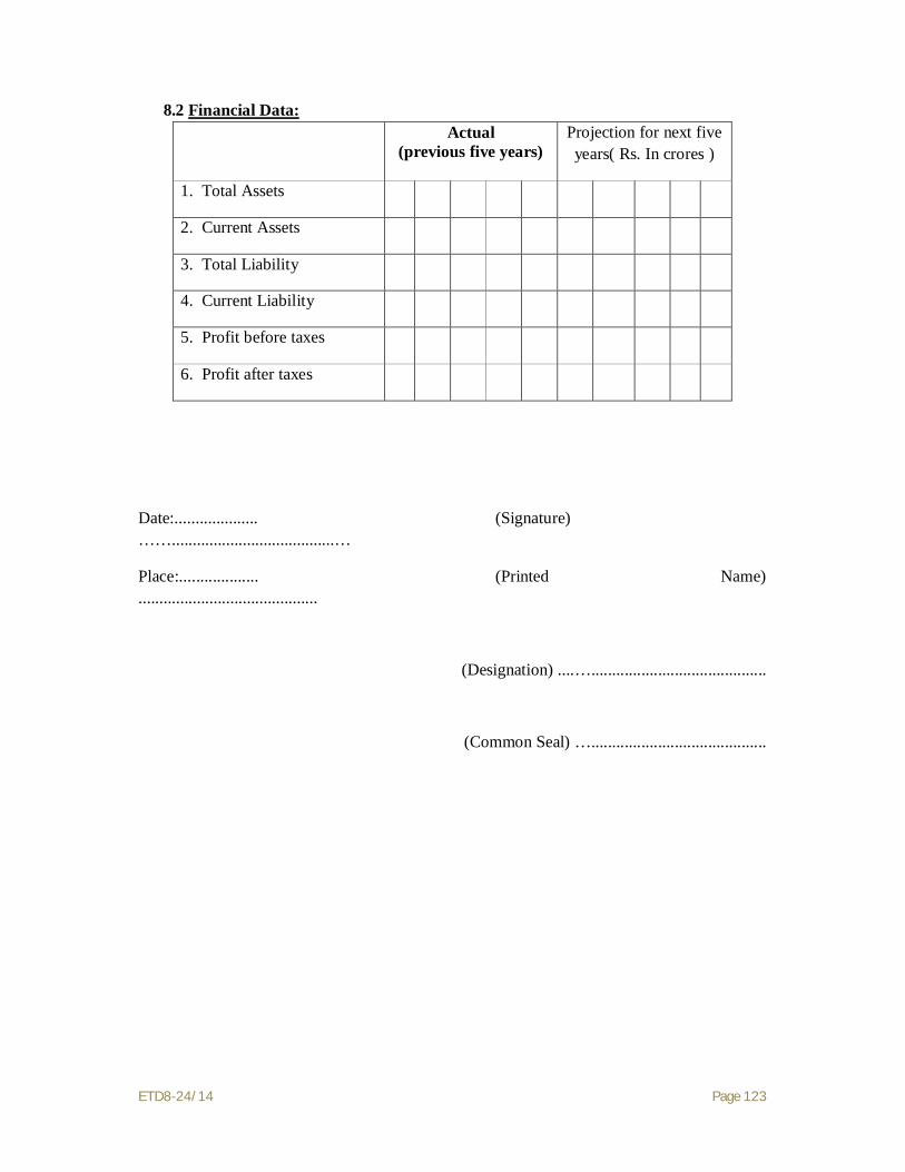
ETD8-24/14 Page 123
8.2 Financial Data:
Date:.................... (Signature) …….......................................…
Place:................... (Printed Name) ...........................................
(Designation) ....…..........................................
(Common Seal) …..........................................
Actual (previous five years)
Projection for next five years( Rs. In crores )
1. Total Assets
2. Current Assets
3. Total Liability
4. Current Liability
5. Profit before taxes
6. Profit after taxes

ETD8-24/14 Page 124
APPENDIX A
APPLICATION FORM (3)
PERSONNEL CAPABILITIES
APPLICATION FORM (3)
Personnel Capabilities
Name of Applicant or Partner of a joint venture
For specific position essential to contract implementation, applicants should provide the names of at least two candidates qualified to meet the specified requirements stated for each position. The data on their experience should be supplied in separate sheets for each candidate.
1. Title of position
Name of prime candidate
Name of alternate candidate
2. Title of position
Name of prime candidate
Name of alternate candidate
3. Title of position
Name of prime candidate
Name of alternate candidate
4. Title of position
Name of prime candidate
Name of alternate candidate
5. Title of position
Name of prime candidate
Name of alternate candidate

ETD8-24/14 Page 125
APPENDIX A
APPLICATION FORM (3 A)
CANDIDATE SUMMARY
APPLICATION FORM (3A)
Candidate Summary
Name of Applicant or Partner of a joint venture
Position Candidate
Prime Alternate
Candidate information 1. Name of candidate 2. Date of birth
3. Professional qualification
Present employment 4. Name of employer
Address of employer
Telephone Contract (manger / personnel officer
Fax Email
Job title of candidate Years with present employer
Summarize professional experience over the last 25 years, in reverse chronological order. Indicate particular technical and managerial experience relevant to the project.
From To Company / Project/Position/ Relevant technical and management experience

ETD8-24/14 Page 126
APPENDIX A
APPLICATION FORM (4)
Financial Capabilities
Application Form-4
Financial information in US$ equivalent/ Rs. In crores
Actual :
Previous five fiscal years
Projected Next two fiscal year
1 2 3 4 5 6 7
1. Total assets
2. Current assets
3. Total liabilities
4. Current liabilities
5. Profits before taxes
6. Profits after taxes
Specify proposed sources of financing to meet the cash flow demands of the Project, net of current commitments.
Source of financing Amount (US$ equivalent)
1.
2.
3.
4.
Attach audited financial statements for the last five fiscal years (for the individual applicant or each partner of joint venture).
Firms owned by individuals, and partnerships, may submit their balance sheets certified by a registered accountant, and supported by copies of tax return, if audits are not required by the law of their countries of origin.

ETD8-24/14 Page 127
SECTION -2
GENERAL CONDITIONS

ETD8-24/14 Page 128
SECTION-2
1.1 GENERAL
1.1.1 These ‘Special Conditions’ shall be read and construed along with General Conditions given in form ‘A’ , Instructions to Tenderers and General Requirement of Specification (Section-1, 2, 3 & 4) of PART-I. However, in case of any conflict or inconsistency between General Conditions given in Form-A, Instructions to Tenderers, General Requirement of Specification, the provisions of Special Conditions of Contract to the extent of such conflict & inconsistency shall prevail. The “Tenderer” wherever used herein shall mean the “Contractor” and the “Purchaser” shall mean “UPPTCL”
1.1.2 U. P. Power Transmission Corporation Ltd. proposes to construct following 400kV DC Transmission lines in Uttar Pradesh on turnkey basis including supply and testing of OPGW but excluding supply of Conductors & Earthwire:
SN Name of Line Double Circuit (Kms) 1 400 kV DC Quad 765 kV Greater NOIDA to 400
kV Greater NOIDA Transmission Line 55
Total 55 1.1.3 The lines shall be constructed on turnkey basis including supply of all materials
required for construction, Optical Fibre Ground Wire (OPGW) and hardware & accessories of OPGW but excluding supply of Conductor and Earthwire. The Conductor and Earthwire shall be supplied by UPPTCL. The prices shall be quoted as per schedules appended at Schedule-A, B, O-1 & O-2.
1.1.4 Completion period of lines shall be mentioned at Schedule-N of Part-I (Section-1) with Tender Bid Part-1.
1.2 SCOPE OF WORKS 1.2.1 Supply 1.2.1.1 Fabrication, Galvanizing, Inspection, testing & supply of all types of 400 kV Double
Circuit towers including stub and stub setting templates, tower extensions, leg extensions, gantry structures (if any), special structures including river crossing towers along with ladders & platforms etc. and Anchor towers (if any), D-Shackles, U-Bolts, hangers, extension links etc. based on drawings and Bill of Material provided by the purchaser. The tower members like U-Bolt, D-Shackle, hangers, extension links etc. shall be supplied complete with required number of bolts, nuts, washers, split pins etc. Fabrication of proto type towers, its assembly and proto inspection is also covered under the scope. Necessary quantities of steel and zinc of tested quality for fabrication and galvanizing of tower parts shall be arranged by the tenderer himself and UPPTCL shall in no way be responsible for arranging the same and shall not accept any responsibility/ liability in this connection.
1.2.1.2 Supply of Bolts &Nuts, Anti-theft bolts & nuts, step bolts and washers, as required,
conforming to relevant IS, including wastage etc. 1.2.1.3 Supply of all types of tower accessories like phase plate, danger plate, number plate,
circuit plate, anti-climbing device & earthing material etc.

ETD8-24/14 Page 129
1.2.1.4 Supply of insulators, hardware fittings, conductor accessories, G.S. Earthwire accessories, OPGW and its Hardware & accessories and other associated required accessories etc. from approved Vendors.
1.2.1.5 The tenderer shall be responsible for coordinating and arranging inspection and testing of items to be supplied by him including proto assembly inspection of all types of towers, extensions, leg extensions stubs and stub setting templates etc. at the manufacturer’s works in the presence of purchaser’s representatives.
1.2.1.6 The design of special structures including river crossing towers and anchor towers if any, and their foundations other than those supplied by the owner, encountered during erection of line , shall also be under the scope of this tender.
1.2.1.7 Supply of Span markers and Night markers etc. including all materials conforming to aviation requirement as per IS 5613, wherever applicable.
1.2.1.8 Supply of ACSR ‘MOOSE’ Conductor, GS earth wire is not under the scope of this tender but shall be arranged and supplied by UPPTCL to the contractor.
1.2.2 Construction of line(s)
1.2.2.1 Route alignment, detailed survey & preparation of profile of 400 kV DC
transmission lines shall be carried out by the contractor and got approved by the supervising engineer.
1.2.2.2 Tower spotting, optimization of tower locations and preparing tower schedule of 400 kV DC lines as detailed above and got approved by the supervising engineer.
1.2.2.3 Preparation of final tower schedule and profile of the line as per Sag Template and tower spotting data to be provided by the Purchaser for approval of Supervising Engineer.
1.2.2.4 Check survey & peg marking and Soil resistivity measurement. 1.2.2.5 Geotechnical investigation. 1.2.2.6 Classification of foundation for different types of towers, excavation, stubs setting,
casting of foundation. However casting of well / pile foundations is not under scope of this tender which shall be arranged by UPPTCL.
1.2.2.7 Erection of all types of towers, gantry structures, if any, erection of special structures including river crossing towers and anchor towers, if any, tack welding of bolts & nuts including supply and application of zinc rich primer and two coats of enamel paint, tower earthing, fixing of tower accessories.
1.2.2.8 Stringing of conductor and earth wires (one no. G.S. Earthwire and one no. OPGW) with the help of Tension Stringing Equipments including installation of hardware and insulator strings, along with all accessories, as the case may be, testing and commissioning of erected line(s). The contractor has to completely erect and commission the line(s).
1.2.2.9 Unloading and taking delivery of all materials to be supplied by the contractor and the purchaser, transporting them to the contractor depots, sorting and stacking them in proper storage sheds and yards provided by the contractor, safe custody of all materials.
1.2.2.10 Testing of stone metal, sand, concrete etc whenever/ wherever required by the Supervising Engineer.
1.2.2.11 Distribution of all materials to the respective tower sites. 1.2.2.12 Supply of cement, stone metal, sand, stone pad reinforcement bars etc. to be used
in foundation work shall conform to relevant IS and shall be arranged and supplied by the contractor without any extra cost to UPPTCL.
1.2.2.13 Painting of towers and erection of Span markers and night markers including all materials, conforming to aviation requirements wherever applicable as per IS 5613.

ETD8-24/14 Page 130
1.2.2.14 Tools and Plants required for construction of the transmission lines at various stages shall be arranged by the contractor at his own cost.
1.2.2.15 Storage-cum-erection insurance of all materials used/ to be used on lines. 1.2.2.16 Complete erection, testing and commissioning of the lines. 1.2.2.17 Safe custody and proper maintenance of completed transmission lines till the same
are taken over by the purchaser. 1.2.2.18 Return of stub setting template and all surplus materials to UPPTCL’s nearest
departmental stores. 1.2.2.19 All necessary provisions of rules & regulations of State/ Central Government or
any other statutory authority relating to navigation, Aviation, Railways, Roads, PTCC, forest etc. are to be complied by the contractor.
1.2.2.20 Supply and erection of any other items not specifically mentioned in this specification but are essential for the successful erection & commissioning of the transmission lines, unless specifically excluded under the scope of this tender, shall also be the responsibility of the contractor.
1.2.3 General Scope of works :
1.2.3.1 The scope of works of the Contractor shall cover, in complete conformity with the Specification, the following:
a) The overall project management, manufacture, factory testing, transportation, delivery to the Sites, unloading, storing, handling erection and commissioning, acceptance testing, placing in successful commercial operation of the complete Transmission line.
b) The provision and maintenance of all temporary site construction facilities, offices, storage, communications, personnel and material transportation, water distribution, power distribution and all other materials and services including, if necessary, camps, catering and any other facilities’ which may be required by legal dispositions, all labour and constructional equipment, management and supervisory staff required to construct and commission the transmission line.
c) To ensure the strength of all parts , material and equipment to withstand all stresses including electrical, mechanical , seismic and other forces which may be normally experienced or expected during long term transmission line operation as well as those stresses caused by faults , switching operations and abnormal system conditions. Correct application and the satisfactory and proper performance of all materials, structures, insulators & hardware , conductor & earthwire accessories and services under all specified operating conditions without signs of undue strain and without breakdown, damages or deterioration of any of the line material due to faulty or unsuitable material, equipment , workmanship, design, erection, construction, installation and commissioning.
d) Correct, safe and proper installation of all towers & line materials at the sites. e) Safe transportation of all structures and line materials from the places of
manufacture to the Site. The Contractor shall ensure that all transported parts, weights and sizes are adequate for loading, unloading and transport conditions.
f) Preparation of detailed soil reports including recommendation and providing technical details as & when necessary.
g) The Contractor shall be responsible for adhering to the time schedule of all phases of works as well as for the coordination of the activities and work forces of all suppliers and / or subcontractors.

ETD8-24/14 Page 131
h) The Contractor shall be responsible for coordinating all work and shall ensure that all components and hardware are compatible to permit the connections between the overhead transmission system and the substation gantry structures.
i) The Contractor shall coordinate with his material suppliers so that the delivery of these items is compatible with the construction schedule.
j) UPPTCL may, require the Contractor to provide suitable training for operation and maintenance of lines to specific number of teams of UPPTCL personnel of different rank (to be specified later).
The Contractor shall schedule all type testing, if required, proto inspection and acceptance testing of materials and equipment to be witnessed by the Engineer in a timely fashion which is compatible with delivery of equipment to the job site. Such schedule shall be prepared in advance with the consultation of the Engineer.
1.3 PREQUALIFICATION OF VENDORS Prequalification of vendors shall be as per clause 1.2 of Part-I, Section-I
(Instruction to Tenderers) of specification.
1.4 VALIDITY 1.4.1 The bid shall be valid for a period of six months from the date of opening of Part-1.
1.5 SCHEDULES AND APPENDICES
i) Forms /schedules and appendices are given in Part-I & Part-II. The bidder is required to go through the complete specification and consult explanatory notes before filling in the various schedules.
ii) All the schedules shall be filled in by the tenderer and complete information shall be supplied. Unsigned and incomplete schedules may make the tender liable for rejection.
iii) The Tenderers may note that the quantities entered in the ‘Price Schedule’ are provisional. However, the actual quantities of supply & erection work shall be as per approved survey.
1.6 EARNEST MONEY 1.6.1 Earnest Money for full tendered quantity of 55 Km shall be Rs. 45 Lacs. Earnest
Money should be in form of Bank Guarantee in the prescribed Proforma /Bank Draft in favour of U. P. Power Transmission Corporation Ltd, Lucknow (Account No. 30231982762, IFS Code SBIN0003347) payable at Lucknow.
1.6.2 The Earnest money shall be furnished in the form and manner as specified in clause no. 1.3.3.1 of “Instruction to Tenderers” of Part-I with partial modification of clause no. 1.3.3.1(b) of above, to the extent that stamp duty in case of Earnest Money, submitted in the form of Bank Guarantee, will be @ Rs. 5.00 per Rs. 1000=00 of B.G. amount subject to the maximum of Rs. 10,000=00 as per Amendment in Indian Stamp Act 1899. The Bank Guarantee is to be kept valid for a period of minimum 6 months from the date of opening of Part-I or any extended date thereof with further three months claim period.

ETD8-24/14 Page 132
1.7 DRAWINGS
1.7.1 In addition to clause no. 3.4 of section-3 ‘General Requirement of Specification (Commercial)’ following shall also apply in respect of drawings to be supplied by contractor :-
1.7.2 Shop drawings, Bill of material and structural drawings of normal tower and extensions shall be supplied by the purchaser. However shop drawings of special structures including river crossing towers if any, shall be developed by the contractor based on design structural drawings and Bill of material to be approved by the purchaser. After inspection of proto assembly contractor shall submit 10 copies each of the structural drawings, Bill of material, shop drawing, foundation drawings etc. of all the towers, extensions, templates etc. after incorporating proper name plate, specification no., name of line etc as per clause no. 3.4 of General Requirements of Specification (Technical) Section-3 along with five (05) sets of soft copies (CDs).
1.7.3 After approval of vendors, the contractor shall submit drawings of line materials in accordance with technical specification for approval of owner as per following: -
1.7.4 Fully dimensioned drawing giving assembly and details of each type of insulators, hardware and accessories. All drawings submitted by the Contractor including those submitted at the time of Bid shall be in sufficient detail to indicate the type, size, arrangement, dimensions, material description, Bill of Materials, weight of each component break-up for packing and shipment, fixing arrangement required, the dimensions required for installation and any other information specifically requested in these specifications.
1.7.5 Technical details with descriptive literature and dimensioned drawings, for equipment offered.
1.7.6 Separate detailed dimensioned drawings of all hardware fittings such as conductor and earthwire suspension/ tension clamps, anchor shackle, ball clevis, socket clevis, clevis eye, yoke plates, chain links, arching horns etc. and their attachments to the strings.
1.7.7 The grade of material used for various parts shall be clearly specified on the drawings as well as in the separate statement viz. Stainless steel, mild steel, forged steel, copper, phosphor bronze, brass etc. and its composition as well as IS/ BS/ IEC specification or any other specification to which the material conform.
1.7.8 Guaranteed Technical Particulars of all the line materials at the time of obtaining vendor approval. The values as per latest revision of the relevant IS shall be given by the contractor.
1.7.9 The contractor shall submit 3 sets of drawings of final route survey and profile etc. with necessary details to the supervising engineer for his approval. After the scrutiny of the drawings by the Supervising Engineer and after incorporating all the modifications as mutually agreed, the contractor will submit the final drawings drawn in ink on good quality tracing cloth or film print for final approval along with requisite number of copies as desired by the Supervising Engineer. The Supervising Engineer will formally approve the tracing/ drawing and will supply two copies of approved drawings to the contractor for his use.
1.7.10 On the completion of work, the contractor will supply to the Supervising Engineer free of cost, the complete ‘as executed’ drawings of the line showing each and every structure, giving type of tower and extension, if any, used and type of foundation casted, double insulator point, roads, railway crossings, all major or small river crossings etc together with measured spans on scale of 20 metres equal to 1 cm horizontal and 2 metres equal to 1 cm vertical. At all deviation (diversion) points,

ETD8-24/14 Page 133
the angle shall be marked in degrees. All kuchcha and metal roads, trees, structures, ponds and other obstructions etc. within 50 meters on either side of the route shall be clearly indicated. The drawings will be drawn in ink on good quality tracing cloth/ film prints. These drawing shall also show telecommunication or power lines within 30 meters on either side of the line(s).
1.7.11 Any other drawings, which are required for construction of line(s) during currency of the contract.
1.7.12 Following is the general list of the documents and drawings that are to be approved by the Owner.
a) Work Schedule (Master Network) Plan. b) Detailed survey report and profile drawings showing ground clearance and
tower locations (as applicable). c) Tower schedule and foundation classification for individual tower
locations. d) Soil Investigation report.
e) Tower accessories drawings like danger plate, number plate, phase plate, Tower footing earthing drawing etc.
f) Manufacturing Quality Plan & Field Quality Plan. g) Vendors approval, h) Line material drawings. i) Type test report of line materials. j) Stringing procedure & stringing chart. 1.7.13 All rights of the design/ drawing for all types of towers and foundations shall be
strictly reserved with the Purchaser only and any designs/ drawings/ data sheets submitted by the contractor from time to time shall become the property of the Purchaser. Under no circumstances, the Contractor shall be allowed to use or offer above designs/ drawings/ data sheets to any other authority without prior written permission of the Owner. Contractor shall have to give an undertaking in this regard on non-judicial stamp paper of Rs. 100/-. Any deviation to above is not acceptable and may cause rejection of the bid.
1.7.14 The drawings and design data supplied by the contractor shall become the property of the UPPTCL and its authorized representative(s) shall be at liberty to use these in any manner as it likes for its future lines without any consent of the contractor.
1.7.15 All drawings shall be prepared using AutoCAD software version 2000 or later only. Drawings, which are not compatible to AutoCAD software version 2000 or later, shall not be accepted. After final approval, all the drawings (structural drawings, BOMs, shop sketches, tower accessories drawings, and insulator/ hardware drawings) shall be submitted to the Owner in CDs.
1.8 ARRANGEMENT OF MATERIAL 1.8.1 All the material required in connection with the fabrication of tower parts, Bolts,
nuts & washers, OPGW and its Hardware & Accessories, line material, supply and installation of aviation requirement and also material for construction of transmission lines i.e. cement, stone metal, sand, stone pad, reinforcement steel bars etc, shall be as per relevant IS and arranged and supplied by the Contractor. The Contractor shall also be responsible for the timely procurement of all the materials so that the supply and erection work is completed within the schedule time.
1.8.2 The following provisions shall apply in connection with the procurement of steel, zinc and fasteners :
ETD8-24/14 Page 134
(a) The steel used for the fabrication of tower parts shall be Mild/ HT steel of tested quality conforming to relevant standard as given in Clause 1.2 of Technical specification- Section-IV.
(b) The tenderer should take into account the fabrication wastage while quoting the rates. The Corporation shall not accept any liability in connection with the wastage of steel, wastage of Bolts & nuts during fabrication or otherwise.
(c) Substitution, if any, of steel section of the tower parts by higher size, due to their non-availability or otherwise shall be to the Contractor’s account. The purchaser shall not accept any liability on this account. Prices of the Tenderers who do not agree to this clause shall be loaded for an increase in cost equivalent to 5% additional steel weight while computing their prices.
(d) The steel shall be procured exclusively from the Main steel producers i.e. SAIL, TISCO, IISCO, Rashtriya Ispat Nigam. In case of non availability of any sections from the main producers, the same can be procured from rerollers approved by SAIL/ TISCO/ PGCIL. For rerollers the specific approval of purchaser is to be obtained.
1.8.3 The Zinc use for galvanizing of fabricated material shall be high grade Electrolytic Zinc of 99.95% purity conforming to IS: 209 with its latest amendment.
1.8.4 Bolts, nuts & washers including antitheft bolts and nuts shall conform to relevant IS given in clause 1.2.2 of Technical specification Section-IV. The Bolts, nuts & washers including antitheft bolts and nuts shall be procured from reputed manufacturers only for which vendor approval is to be taken from the purchase
1.9 PROTO ASSEMBLY INSPECTION
1.9.1 The contractor shall offer proto-type of templates and towers of each type along
with stubs and extensions fabricated and assembled in horizontal position for inspection. The mass fabrication shall be taken up only after approval of proto assembly.
1.10 TESTS & TEST CERTIFICATES The type, acceptance and routine tests and tests during manufacture shall be carried-
out on the material and shall mean as follows:
1.10.1 Type Test Type Tests shall mean those tests which are to be carried out to prove the process of
manufacture and general conformity of the material to this Specification. These tests shall be carried out on samples prior to commencement of commercial production against the order. The Bidder shall indicate his schedule for carrying out these tests.
1.10.2 Acceptance Test
Acceptance Tests shall mean those tests which are to be carried out on samples taken from each lot offered for pre-dispatch inspection, for the purposes of acceptance of that lot.
These tests shall be conducted as per QAP approved by the Purchaser on each lot of finished material, which is ready for despatch. The tests shall be conducted in the presence of the Purchaser’s authorized representative(s). After the material has been subjected to Acceptance Test, the test report shall be prepared. In case the material is not found suitable, the defects shall be pointed out to the Contractor, who will take the necessary corrective action in consultation with the Purchaser. The

ETD8-24/14 Page 135
rectification of defects shall be done by the contractor at his own cost and material re-offered for inspection. However the delay in the time schedule due to this reason shall not be permitted.
After the material has been found acceptable, a Material Despatch Clearance Certificate (MDDC) shall be issued in writing by the Purchaser’s representative(s) without which the material shall not be dispatched.
The acceptance of any batch of items, after acceptance tests or otherwise, shall in no way relieve the Contractor of any of his responsibilities of meeting all the requirements of the specification and shall not prevent subsequent rejection. In case any item of that batch is later found to be defective, the contractor in such case shall replace the defective items free of cost and shall not delay the time schedule.
1.10.3 Routine Test Routine Tests shall mean those tests, which are to be carried out on the material to
check requirements which are likely to vary during production. These tests shall be conducted on raw materials, in process material, and finished material in accordance with approved QAP, by the Contractor himself. Routine tests shall be conducted regularly and properly on the material, so as to ensure that the material has been manufactured as per requirement of this specification. Proper records of the tests shall be maintained by the contractor, and shall be made available to the purchaser as and when required. In case above provision is not followed the material offered for inspection is liable to be rejected.
1.10.4 Test During Manufacture Tests During Manufacture shall mean those tests, which are to be carried out during
the process of manufacture and end inspection by the Contractor to ensure the desired quality of the end product to be supplied by him.
1.10.4.1 The norms and procedure of sampling for these tests will be as per the Quality Assurance Programme to be mutually agreed to by the Contractor and the Owner.
1.10.4.2 The standards and norms to which these tests will be carried out are listed against them. Where a particular test is a specific requirement of this Specification, the norms and procedure of the test shall be as per specification or as mutually agreed to between the Contractor and the Owner in the Quality Assurance Programme.
1.10.4.3 For all type and acceptance tests, the acceptance values shall be the values specified in this specification or guaranteed by the Bidder, as applicable.
1.10.4.4 Correct grade and quality of all the materials including steel and zinc shall be used by the contractor/ vendor.
1.10.4.5 Purchaser reserves the right of carrying out any inspection or test of reasonable nature at the Contractor’s or sub-contractor’s work or at site, or at any approved laboratory in addition to the tests as specified above to satisfy itself that the materials comply with the specification.
1.10.4.6 The contractor shall follow the approved QAP in true spirit. If desired by the Engineer he shall give access to all the documents and equipment to satisfy the Engineer that QAP is being followed properly.
1.11 Inspection, Testing & Inspection Certificate: This clause is to be read with clause no. 3.10 of General Requirements of
Specification (Technical) of Part-I Section-3. 1.11.1 Engineer, his duly authorized representative and/ or an outside inspection agency
acting on behalf of the purchaser shall have at all reasonable times access to the Contractor’s premises, stores or works and shall have the power, at all reasonable

ETD8-24/14 Page 136
times to inspect and examine the materials and workmanship during its manufacture and if part of the works is being manufactured or assembled on other premises or works, the Contractor shall obtain for the Engineer or for his duly authorised representative permission to inspect as if the Works were manufactured or assembled on the contractor’s own premises or works. All help shall be given by the Contractor for carrying out such inspection.
1.11.2 The inspection call shall be given by contractor along with the routine tests reports when the goods have actually become ready in all respects in the works of their manufacturer and not on the basis of anticipated date of completion.
1.11.3 A period of 4 weeks or 6 weeks shall be allowed for UPPTCL for making travel arrangement for their inspecting officer(s) to reach their works. This period of 4 or 6 weeks will be from the date of inspection call received by UPPCL. The period of 4 weeks shall be for works situated in U.P., Union Territory of Delhi, Rajasthan, Bihar and West Bengal and 6 weeks for all the remaining States. In case the goods are not available for inspection at the time of the arrival of the inspecting officer(s) the firm shall pay UPPCL a sum of Rs. 1000/- (Rs. one thousand only) per day per inspecting officer from the date of departure to the date of arrival (both includes) of the engineer concerned and charges of futile journey as intimated by the “Engineer” of the contract.
1.11.4 The Engineer or Inspector shall, within fifteen (15) days from the date of inspections as defined herein, give notice in writing to the contractor of any objection to any drawings and all or any equipment and workmanship which in his opinion is not in accordance with the Contract. The contractor shall give due consideration to such objections and shall either make the modifications that may be necessary to meet the said objections or shall confirm in writing to the Engineer/ Inspector giving reasons therein, that no modifications are necessary to comply with the Contract.
1.11.5 In all cases where the Contract provides for the tests whether at the premises of the Contractor or at the works of any Sub-Contractor, the Contractor, except where otherwise specified, shall provide free of charge such items as labour, materials, electricity, fuel, water, stores, apparatus and instruments as may be reasonably demanded by the Engineer/ Inspector or his authorized representative to carry out effectively, such test of the equipment in accordance with the Contract and shall give facilities to the Engineer/ Inspector or to his authorized representative in the accomplishing testing.
1.11.6 The inspection by Engineer and issue of Inspection certificate thereon shall in no way limit the liabilities and responsibilities of the Contractor in respect of the agreed Quality Assurance Programme forming a part of the Contract.
1.11.7 After successful inspection and tests, the purchaser shall issue a material dispatch clearance certificate authorizing the contractor to dispatch the inspected/ tested material. No material shall be dispatched without issue of dispatch clearance certificate from the Purchaser.
1.11.8 The inspection may be waived off by the purchaser, if needed. 1.11.9 The inspection by Engineer/ Supervising Engineer or their authorized representative
and issue of exemption certificate thereon shall in no way limit the liabilities and the responsibilities of the contractor in respect of agreed Quality Assurance Programme forming a part of the contract.
1.12 PERMITS AND PRIORITIES 1.12.1 Necessary permits, if any, required for execution of the contract shall be arranged
by the contractor himself. However, UPPTCL may assist the contractor for
ETD8-24/14 Page 137
obtaining permits required for the operation of vehicles etc. used for the construction work.
1.12.2 UPPTCL may, however furnish to the contractor such certificate as may be required for necessary allocation of controlled commodities needed for the execution of works, if UPPTCL considers the demand justified.
1.12.3 UPPTCL will, however, not be responsible for the delay in the execution of the contract if permits and priorities are not granted in time.
1.13 DESPATCH OF MATERIAL No material shall be despatched by the Contractor without the MDCC from the
UPPTCL. This provision shall apply for all the materials to be supplied by the contractor directly or through vendors.
1.14 PACKING 1.14.1 All the materials shall be suitably protected, coated, covered or boxed and crated to
prevent damage or deterioration during transit, handling and storage at Site till the time of erection. The Contractor shall be responsible for any loss or damage during transportation, handling and storage due to improper packing.
1.14.2 The Contractor shall include and provide for securely protecting and packing the materials so as to avoid loss or damage during transport by air, sea, rail and road.
1.14.3 All packing shall allow for easy removal and checking at site. Wherever necessary, proper arrangement for attaching slings for lifting shall be provided. All packages shall be clearly marked for with signs showing ‘up’ and ‘down’ on the sides of boxes, and handling and unpacking instructions as considered necessary. Special precaution shall be taken to prevent rusting of steel and iron parts during transit by sea.
1.14.4 The cases containing easily damageable material shall be very carefully packed and marked with appropriate caution symbols, i.e. fragile, handle with care, use no hook etc. wherever applicable.
1.14.5 Each package shall be legibly marked by the Contractor at his expenses showing the details such as description and quantity of contents, the name of the consignee and address, the gross and net weights of the package, the name of the Contractor etc.
1.14.6 Angle section shall be wire bundled. 1.14.7 Cleat angles, gusset plates, brackets, fillet plate, hanger and similar loose pieces
shall be stacked and bolted together in multiples or securely wired through holes. 1.14.8 Bolts, nuts washers and other attachments shall be packed in double gunny bags
accurately tagged in accordance with the contents. 1.14.9 The packing shall be properly done to avoid losses & damages during transit. Each
bundle or package shall be appropriately marked 1.14.10 Necessary procedure for packing shall be followed before dispatch of material, as
given in ‘Technical conditions’. 1.15 ADVICE NOTES Copies of all advice notes covering goods despatched to site shall be submitted at
the time of despatch and items therein shall bear serial numbers in the schedule of material. The advice notes shall be submitted to the Purchaser, who will use them for verification purposes against invoice submitted for payment.
ETD8-24/14 Page 138
1.16 RECEIPT OF MATERIALS 1.16.1 The contractor shall take delivery of all materials at site by road transport, otherwise
from destination railway station. The contractor shall be responsible for timely unloading the materials from wagon/ trucks, taking delivery and carting the received materials to the different stores established by him or to the site of work without any extra charges from UPPTCL. Purchaser supplied material may also be handed over from nearby UPPTCL stores.
1.16.2 The contractor shall be responsible for all the demurrage/ wharfage charges levied, if, any, due to delay in unloading the material from railway wagons or in taking delivery from railway.
1.16.3 The contractor shall be responsible for making and settling claims with railways or transport authority or suppliers in case material is received short or damaged.
1.16.4 The contractor shall be fully responsible for proper handling, safe custody and maintenance of the materials received by him from the date of their receipt till the end of the taking over/ material reconciliation whichever is later.
1.17 STORAGE OF MATERIAL 1.17.1 The contractor shall be required to set up stores at suitable place(s) along the route
of the line to receive and store the materials. These stores shall be open for inspection by the UPPTCL’S staff as and when desired by the UPPTCL.
1.17.2 The contractor shall make arrangements to take delivery of all the materials and stock them properly.
1.173 The cost of handling, storage and insurance of materials shall be included in the quoted erection rates of the price schedule.
1.17.4 The store shall be kept insured as per provisions of this contract. 1.17.5 In case the stores are not set up by the contractor in time, the materials shall be
temporarily stored by UPPTCL at the risk and cost of the contractor and the handling, transportation, storage and other charges shall be recovered from the contractor’ s bills or otherwise.
1.18 INSURANCE
In addition to conditions specified in Clause No. 2.11 Section-2 “General Requirement of Specification (Commercial)” following shall also apply:
1.18.1 The materials that would be supplied by the Contractor and other suppliers on behalf of the Contractor shall be insured against all transit risks and up to 45 days after their arrival at destination or at the F.O.R. destination railway station. The charges for insurance against transit risks and up to 45 days after their arrival at destination shall be included in the rates for supplies and will not be paid extra by UPPTCL.
1.18.2 All the Contractor and purchaser supplied material and the line under erection, shall be kept completely insured by the contractor at his cost for the losses, deterioration, theft, damage, pilferage, fire, etc. from time of dispatch from the Contractor’s works/Sub-vendor’s works, up to the completion of erection, testing & commissioning at site and taking over of the transmission line by UPPTCL in accordance with the Contract. The storage cum-erection insurance shall be arranged by the contractor in his own name and charges included in the erection rates and shall not be paid extra by the UPPTCL.

ETD8-24/14 Page 139
1.18.3 Any other insurance including the insurance of erection personnel employed by the contractor shall also be the responsibility of the contractor and shall be done by the contractor at his own cost.
1.18.4 The contractor shall be fully responsible for safe custody of all the materials supplied to him for the erection of the line.
1.19 DEVIATIONS Unless brought out clearly, the tenderer shall be deemed to conform strictly to the
provisions of the tender documents. All deviations from the specifications shall be clearly brought out in respective schedule of deviations. Any discrepancy between the specification and the catalogue of the tender, if not clearly brought out in the respective schedule, shall not be considered as a valid deviation.
1.20 REPLACEMENT/ RECTIFICATION OF DEFECTIVE MATERIAL/ WORK 1.20.1 Any material supplied by the contractor found defective or any erection work, if
done defectively, shall be replaced/ rectified by the contractor free of cost. 1.20.2 The contractor shall be fully responsible for the proper up-keep of goods supplied
by the UPPTCL or contractor. The responsibility of the contractor in this regard shall continue till the completed transmission line is taken over by the Supervising Engineer. In the event of goods in possession of contractor being lost/ damaged, the contractor shall be liable to make good the loss without any extra charges to the purchaser.
1.20.3 All work in connection with making and settling of claims etc with the appropriate authorities shall be carried out by the contractor, but completion of line shall not be delayed on this account.
1.21 ERECTION TOOLS 1.21.1 All the erection tools and plants required for and during the construction of the line
shall be arranged by the contractor at his own cost. The contractor shall ensure that tools and plants required for erection of transmission line(s), other associated equipments viz. TSE etc. are available with him sufficiently in advance. No delay in completion period will be accepted if necessary tools and plants are not arranged by the contractor in time.
1.21.1 The stub-setting templates supplied by the purchaser to the contractor shall be returned back to the purchaser in good working condition on completion of work. In case these are lost or damaged by the contractor during storage/construction, the cost of the same, as may be decided by the Supervising Engineer, shall be deducted from the contractor’s bills or recovered otherwise.
1.22 USE OF ROAD The contractor may be allowed to use private roads built by UPPTCL in connection
with the construction works. UPPTCL may also help in obtaining permission for using canal service roads for transport of contractor’s men and materials wherever possible under the rules. This will, however, not be binding on UPPTCL and no delay in start or completion of work shall be accepted on this account. Any charges levied by the concerned authorities for use of canal roads etc. shall be borne by the contractor.

ETD8-24/14 Page 140
1.23 WAY LEAVE 1.23.1 The necessary way leave in connection with construction of line shall be arranged
by the Supervising Engineer of the purchaser. 1.23.2 However, the contractor shall extend all help including supply of necessary
documents and information required in connection with the way clearance relating to the following:- (i) Railway crossing/Highway crossing (ii) PTCC (iii) Airport/ Field (iv) Forest/ Tree cutting (v) Crop/ Tree compensation (vi) Any other clearance
1.23.3 The contractor shall inform the Supervising Engineer about the places where there is way leave problem including forest areas sufficiently in advance so that the required way leave can be arranged in time. Proposals for way leave and right of way shall be prepared and submitted by the contractor complete with details of type/ size (diameter/ circumference) and number of trees along with the name of the owner thereof duly verified by local District/ Revenue authorities. Permission will be obtained by the Supervising Engineer within reasonable time for which due notice and time shall be given by the contractor. UPPTCL shall not be held responsible for any claim on account of damage done by the contractor or his gangs to trees, crops or other property without authority from the Supervising Engineer. If any litigation/ court case crop up due to lapse(s) on the part of the contractor, the contractor shall resolve the same themselves. Crop compensation and compensation for tree cutting shall be borne by UPPTCL.
1.23.4 The contractor shall take all possible steps so that the damage to crops etc. is kept to a minimum and in the event of unavoidable extensive damage to the ripe or the partially developed crops, the contractor is to note the extent of damage, the time of occurrence, name of the crop, plot number the name of the owner and the contractor must submit such reports to the Supervising Engineer.
1.24 COMPLIANCE WITH REGULATIONS 1.24.1 Unless otherwise specified all works shall be carried out in accordance with Indian
Electricity Act, 2003, Indian Electricity Rules,1956 with the latest amendments or revisions thereof which may be issued during the currency of the contract and the requirement of any other Regulations and Acts in India to which UPPTCL may be subjected to.
1. 24.2 All railway tracks/ power/ communication line or other important road crossings etc. or routing the line through air field region shall conform to the relevant rules and procedures laid down by the Railway, Communication, Aviation or other concerned authorities.
1. 24.3 On the towers in the vicinity of civil/ military aerodromes or Air Field Regions, aviation signals are to be provided, as per provisions of IS: 5613(part 3) (Section 1).
1.25 COMMENCEMENT OF ACTIVITIES 1.25.1 Commencement of following activities is subject to the prior and specific approval
of the items mentioned against each by the Engineer/ Supervising Engineer:

ETD8-24/14 Page 141
S.No. Activity Items for which prior approval is necessary from purchaser
(A) SUPPLY OF TOWER
1. Manufacture of Tower QAP, Proto Assembly, Approval of vendors for steel &zinc
2. Manufacture of Bolts & Nuts
QAP, Vendor approval for Bolts & nuts
3. Despatch of Towers, Bolts & nuts & Tower accessories
Acceptance test & MDCC
(B) SUPPLY OF OPGW AND LINE MATERIAL
1. Manufacture of line materials
Approval of Vendors, Drawing, GTP & QAP
2. Despatch of line material
Acceptance Test & MDCC
(C) CONSTRUCTION OF LINE(S)
1 Route profile Field Quality Plan and Sag-Template
2 Foundation work Field Quality Plan, Classification of foundation and stub setting work
3 Erection of towers Field Quality Plan
4 Stringing of wires Field Quality Plan, Stringing charts and stringing method
1.26 DATE OF COMPLETION Completion Period of the 400 KV DC lines shall be 08 months from the date of
issue of LOI per details mentioned below:-
S.N. Name of Line Double Circuit (Kms)
Date of completion
1- 400 kV DC Quad 765 kV Greater NOIDA to 400 kV Greater NOIDA Transmission Line
55 08 months from issue
of LOI

ETD8-24/14 Page 142
1.27 PROJECT MONITORING
1.27.1 After the award of the contract, the contractor, in consultation with Engineer/ Supervising Engineer, shall prepare a detailed time schedule for each activity and relating various activities with each other in chronological sequence.
1.27.2 The time schedule shall be submitted in the form of Bar and PERT Chart giving broad schedules of main activities such as preparation of shop drawings, procurement of raw material, manufacture and supply of towers including bolts, nuts & washers, tower accessories, and line material, survey, construction of foundation, erection of towers, Stringing and testing and commissioning. In this chart, both commencement and completion dates of each activity are to be indicated.
1.27.3 During the currency of the contract, the contractor shall furnish the following reports to the Engineer and Supervising Engineer in the prescribed formats and charts: a) Monthly progress reports for engineering activities giving scheduled and
actual progress of the preparation of shop drawings and manufacture of tower parts for proto assembly tests.
b) Monthly progress report of supply of line materials. c) Fortnightly progress report of the various activities of erection of line(s) as
well as receipt of various materials at site, indicating scheduled and actual progress during the fortnight as well as cumulative progress.
d) Any other progress report as desired by the engineer and/ or Supervising Engineer.
1.27.4 The formats and charts for the above progress report shall be intimated by the Supervising Engineer to the contractor after the award of the contract.
1.27.5 Besides above a periodical review meeting between the contractor and Engineer/ Supervising Engineer shall be held to analyse the scheduled and actual progress targets for the next period and to sort out bottlenecks, if any. The contractor will attend the above meetings along with necessary information in respect of supply and erection activities.
1.28 EXTRA WORKS The rates for works not included in the price schedule will be decided upon, when
any such necessity arises during the execution of the work, by negotiations between the Supervising Engineer and the Contractor and upon the rates having been decided as aforesaid, the Contractor shall perform the work on the terms & conditions as contained in this specification.
1.29 SAFETY OF STAFF AND LABOUR The contractor shall provide and make all necessary arrangements for safety of staff
and labourers at site of work. UPPTCL will not, in any way, be responsible for any accident minor, major or fatal to any person at the site of work or for any damages arising there from during the erection, which shall be contractor’s responsibility. The staff insurance charges, if any, shall also be borne by the contractor.
ETD8-24/14 Page 143
1.30 DESIGN IMPROVEMENT 1.30.1 The Engineer or the contractor may propose changes in the specification of the
equipment or quality thereof and if parties agree upon any such changes, the contract shall be modified accordingly.
1.30.2 If such agreed upon change is such that it affects the price and schedule of completion, the parties shall agree in writing to the extent of any change in the price and/ or schedule of completion before the contractor proceeds with the change thereof. Following such agreements, the provision shall be deemed to have been amended accordingly.
1.31 RESPOSIBILITY OF THE CONTRACTOR 1.31.1 The contractor shall guarantee and be entirely responsible for the execution of the
contract in accordance with the “General Conditions of Contract”, “General Conditions of Contract FORM-A”, “Special Conditions of Contract”, “Technical Conditions of Contract” and Schedules, Appendices, other documents and all clauses of this specification.
1.31.2 The contractor shall guarantee and be entirely responsible for taking delivery of all materials to be supplied by him and by the purchaser, cartage, proper handling and storage of all materials in their custody, line erection, setting to work, testing and commissioning and maintenance of the said line(s), insurance during storage till the line is taken over by the Supervising Engineer.
1.31.3 He shall further guarantee and be responsible for the quality and workmanship of all materials and completed works, correct design and their accuracy conformity of all works to the approved designs and drawings and their proper erection within the guaranteed completion and maintenance period, till the line is taken over by UPPTCL.
1.31.4 The contractor shall be responsible for the timely submission of profiles, classification of foundations etc. as the erection of the line is related to them. He shall also be responsible for obtaining the approval of profiles, classification of foundations etc within the schedule time. In this connection, if necessary he will depute his representative to sort out the matter with the Supervising Engineer.
1.31.5 UPPTCL shall have the right to require the contractor to make any change in the erection practice, which may be necessary in the opinion of the Engineer/ Supervising Engineer to make materials and work conform to the provisions and contents of the specification without extra cost to UPPTCL.
1.31.6 Approval by the Engineer or any authorized representative of UPPTCL, of the contractor’s and sub contractor’s drawing, materials or of other parts of work involved in the contract, or of tests carried out either by the contractor or by the subcontractor or UPPTCL, shall not relieve the contractor of any part of contractor’s obligation of meeting all the requirement of the specification or of the responsibility for the correctness of the contractor’s drawing, supply of material made by him, erection of line etc. who shall also rectify the defects, whenever detected, at his own cost, without delaying the scheduled completion period of the line.
1.31.7 Any work performed prior to the approval of the drawings, tests etc. will be at contractor’s risk.
ETD8-24/14 Page 144
1.32 ENGINEER’S SUPERVISION 1.32.1 To eliminate delays and to avoid disputes and litigation, it is agreed between the
parties to the contract that all matters and questions shall be referred to the Supervising Engineer and his decision shall be final.
1.32.2 The work shall be performed under the directions and supervision of the Supervising Engineer. Scope of duties of the Supervising Engineer, pursuant to the contract, will include but not be limited to the following: - (i) Interpretation of all the terms and conditions of these documents and contract. (ii) Review and interpretation of all the contractor’s drawings, engineering data etc. (iii) Witness or authorize his representative to witness tests and trials either at the
manufacturer’s works or at site or at any place where work is performed under the contract.
(iv) Inspect, accept or reject any equipment, material and work under the contract. (v) Issue certificate of acceptance and/ or progressive payment and final payment
certificate. (vi) Review and suggest modifications and improvement in completion schedule
from time to time. (vii) Supervise the Quality Assurance Programme implementation at all stages of the work. (viii) Upon successful completion and commissioning of the transmission line, the
Supervising Engineer shall ensure reconciliation of material issued to the contractor. If no claim is pending against the contractor, the certificate to this effect shall be issued by the Supervising Engineer.
1.33 REFERENCE AND STANDARDS The codes and/ or standards referred to in this specification shall govern, in all the
cases wherever such references are made. In case of conflict between such codes and/ or standards and the specification/ contract the later shall govern. Such codes and/or standards referred to shall mean the latest revisions/ amendments/changes adopted and published by relevant agencies. In case of any further conflict in this matter, the same shall be referred to the Engineer, whose decision shall be final and binding.
1.34 SUPERVISING ENGINEER The concerned Superintending Engineer, Electricity Transmission Circle, UPPTCL
being called the ‘Supervising Engineer’ will be responsible for construction of the transmission line on behalf of the purchaser/ UPPTCL.
1.35 SPLITTING OF TENDERS UPPTCL reserves the right to split work among as many Tenderers as it may deem
fit.

ETD8-24/14 Page 145
1.36 TAXES & DUTIES 1.36.1 The prices of imported items, if any, shall be inclusive of all taxes, duties, license
fees, import/ custom duties etc. as legally applicable. Any such taxes, duties and levies shall be to the contractor’s account & no separate claim on this account shall be entertained by UPPTCL.
1.36.2 No Excise duty & Sales/ Trade tax/ VAT/ any other taxes and duties in any form shall be payable by UPPTCL on bought-out items which shall be dispatched by Contractor’s sub-suppliers directly to the project site on sale-in-transit basis. All taxes and duties (except Octroi and Entry Tax) shall be deemed to be included in Ex-works prices. Any change in taxes and duties shall be to the contractor’s account. However the applicable Octroi/ entry tax in respect of the said items of supply would be reimbursed to the contractor separately as per actual by UPPTCL subject to furnishing of documentary proof.
1.36.3 The ex-work’s prices of contractor’s self-manufactured items, supplied by Contractor directly from their own works pertaining to direct transaction between Contractor and UPPTCL shall be exclusive of Excise Duty, Concessional Sales/ Trade Tax/ VAT / Octroi/ Entry Tax/ any other taxes, duties & levies which shall be paid extra at actual as legally applicable at the time of supply.
1.36.4 The tenderer shall identify such direct transaction items, which are exclusive of taxes and duties etc. in Price Schedule along with taxes, duties etc. presently payable otherwise taxes, duties etc. shall be deemed to be included in ex-works prices.
1.35.5 The requisite concessional sales tax declaration forms for direct transaction as well as bought out items under sale-in-transit as may be applicable under Central Sales Tax or State law shall be provided by UPPTCL on request of Contractor.
1.35.6 The tenderer shall include Service tax and surcharge/ cess etc. on it, as applicable, in their quoted prices and UPPTCL shall not bear any additional liability on this account.
1.35.7 The contract shall be a ‘Divisible contract’ with single point responsibility, hence no works contract tax shall be payable and UPPTCL shall not bear any liability on this account.
1.35.8 UPPTCL shall not bear any liability towards Turnover tax, corporate tax, sales tax on works contract, income tax and any other such taxes & surcharge/cess on them. Liabilities towards these shall be to Contractor’s account as applicable.
1.35.9 UPPTCL shall be entitled to deduct Income tax and other taxes at source in accordance with provisions of Income tax/ other taxation laws as applicable from time to time.
1.36 MODVAT The tenderer shall quote the prices after taking into account due credit under
MODVAT scheme as per relevant Govt. Policies wherever applicable. UPPTCL shall not bear any liability on this account.
1.37 ADVANCE PAYMENT No payment prior to the despatch of material or work shall be made by UPPTCL
under any circumstances. Tenderers are advised not to ask for any such advance payment, as the same shall not be considered even if the tenderers are willing to pay

ETD8-24/14 Page 146
interest charges thereon. Tenderers asking for advance payment are liable to be rejected.
1.38 ARBITRATION Following may be deemed to be added at the end of para-1 of Arbitration clause no.
38 of FORM-A: - “In case of refusal/ neglect by such nominee, Chairman, UPPTCL may nominate another person in his place.”
1.39 JURISDICTION Clause no. 38-A of FORM-A shall be modified to the extent given below:- “Any action taken or proceedings intimated shall be in principal Civil Court of
original jurisdiction at Lucknow under the High Court of judicature at Allahabad only.”
1.40 NOTICE Any notice given to the Contractor, if UPPTCL thinks necessary, shall be given by
Regd. Post at its Registered Address. 1.41 CLARIFICATION Should any provisions made in the specification be not clear or there be any
ambiguity, the same should be got clarified from the Purchaser before the submission of Tender. After the opening of the tender, the interpretations as made by the purchaser shall be acceptable to the Contractor.
1.42 EVALUATION OF TENDER BIDS
Bidder has to quote for the complete scope of work for the packages. Bids for individual items or incomplete services shall be treated as incomplete and are liable to be rejected.
1.42.1 In addition to clause 1.4.4 under the heading “Evaluation of Tender” of Sec.1 of ‘General Conditions of Contract’ for supply and/ or Erection of transmission line materials’ Part-1, the tenderers may note carefully that in case the prices are not quoted as per Commercial & Technical requirement mentioned in this tender specification document or where the statement/ terms & conditions are ambiguous or not clear or wherever necessary, their offers shall be loaded suitably for the purpose of comparison.
1.42.2 In case rates for any particular item(s) mentioned in the prescribed schedule of prices are not quoted, the offer of such tenderer(s) may be loaded by amount of the highest rate(s) quoted by other tenderers for such item, in order to arrive at the total computed prices for the purpose of comparison.
1.42.3 Bids stipulating commissioning dates beyond that specified in specification run the risk of rejection.
1.42.4 Construction of the contract Contracts shall be entered into on the basis of divisible Supply-cum-Erection Contract
on a single source responsibility basis. The supply portion of the Contract will relate to the supply of equipment and material and the Erection portion will relate to erection, stringing, testing and commissioning etc. as specified in the bidding documents.

ETD8-24/14 Page 147
Two separate contracts, will not, in any way, dilute responsibility of Bidder for successful completion of work and fulfilment of all obligations as per Bidding Documents and that both the contracts will have a cross-fall breach clause i.e. a breach in one Contract will automatically be considered as a breach of the other Contract which will confer on the owner the right to terminate the other Contract at Bidders risk and cost and/ or recover damages under any or both the Contracts.

ETD8-24/14 Page 148
SECTION -3
PRICES

ETD8-24/14 Page 149
SECTION -3
PRICES
2.1 GENERAL
2.1.1 The rates for supply of towers, bolts, nuts & washers, towers accessories, various line materials ,OPGW &, construction of the line covered under this specification shall be given by the tenderer as per following price schedule A, B ,O-1 & O-2 appended with this specification.
Sl. No. Description Reference of Price
Schedule
1. Supply of Towers and line materials A
2. Construction of Line B
3. OPGW and its Accessories O-1 & O- 2
The brief description of items in price schedule shall not be construed to limit the scope of work, and the same shall be read in conjunction with corresponding Sections of General Conditions, Special Conditions and Technical conditions of this Specification.
2.2 SUPPLY (PRICE SCHEDULE: A) 2.2.1 The supply rates mentioned in the price schedule shall include all items covered at
clause no. 1.2.1 ‘Supply’ under heading ‘Scope of works’ of SECTION-1 of ‘SPECIAL CONDITIONS OF CONTRACT’.
2.2.2 Bidder shall quote ex-works/ ex-factory/ ex-showroom (referred to as ‘Ex-works’) price, Freight and Insurance against all transit risk and 45 days after their arrival at destination and Packing & Forwarding, for delivery at F.O.R destination site of all the items indicated in the relevant Price Schedule.
2.2.3 The prices for supply of towers shall be quoted on per M.T. basis as per price Schedule-A. However, the payment shall be released on completed Tower Basis for each type of tower (comprising the Basic Tower Body, Body extensions, wherever applicable, bolts & nuts along with spring washer and step bolts, unequal leg extensions wherever applicable for a completed tower) and on completed Stubs and Cleats set basis for each type of foundation (comprising a set of stubs & cleats, required Bolts and nuts along with Spring Washers) based on the weight of the tower parts and bolts & nuts as per approved Bill of Materials.
2.2.4 Tower shall include structural members like angle sections, plates, pack washers, U-Bolts, complete with bolts, nuts and washers & pins, attachment for installing accessories, extension links, hangers etc. as per bill of material supplied by the purchaser.
2.2.5 The cost of fabricated material shall include cost of necessary quantity of Steel and Zinc & all works relating to fabrication, galvanizing & delivery up to site stores, and other indirect charges incurred in connection with supply of finished material.
2.2.6 The cost of line materials like Insulators, Hardware Fittings for Conductor & Earthwire, Name Plate, Phase Plate etc & Tower accessories, OPGW and its

ETD8-24/14 Page 150
Hardware & its accessories shall be quoted and it should be specifically mentioned whether it is bought out item or self manufactured.
2.3 CONSTRUCTION OF TRANSMISSION LINE (PRICE SCHEDULE: B) 2.3.1 The erection rates mentioned in the price schedule shall include all works covered at
clause no. 1.2.2 ‘Construction of lines’ under heading ‘Scope of works’ of SECTION-1 of ‘SPECIAL CONDITIONS OF CONTRACT’.
2.3.2 The rates include the cost of labour, all tools & plants and other incidental expenses in connection with the erection work pertaining to each item of transmission line(s).
2.3.3 The rates under item ‘Survey’ of the price schedule will not include forest clearance, tree cutting, removal of fallen trees, acquisition of right of way and payment of compensation thereof but include preparation of tower schedules, preparation of profiles, plotting the towers thereon, submission of survey maps etc. as per details given in Technical specification (Part-III). The payment for survey will be made on approval of tower schedule and profiles by Supervising Engineer.
2.3.4 ‘Check Survey’ shall be conducted to make a check on the detailed survey and to locate and peg mark the tower positions on ground conforming to the survey charts. The pit centres shall also be marked according to the excavation charts. The levels up and down of each pit centres with respect to the centre of the tower location shall be noted and recorded. The rate for check survey shall also include the cost of soil resistivity measurement.
2.3.5 Soil investigation shall be for complete soil and geotechnical Investigation work mentioned in Technical specification.
2.3.6 The rates for excavation include necessary earth work for casting of foundation, backfilling, leveling including the cost of borrowed earth if any. No separate charges shall be paid for fallen earth in the pit, when once excavated. Same rate shall be applicable for excavation of foundations for Special River crossing towers, Anchor towers or any other special foundations. The measurement for excavation shall be made on the basis of design excavation volume arrived at considering dimension of pit leaving 150 mm gap around (except for undercut foundations) the base pad or actually excavated whichever is less. The payment for excavation shall be made as per actual type of soil encountered at the time of excavation, but the total payment for excavation portion shall not exceed the amount as payable for excavation considering the soil type same as that of foundation classification. The decision of the Supervising Engineer shall be final and binding with respect to classification of soil and foundations.
2.3.7 The rates for stub-setting include all the works related to correct setting of stub at exact locations and alignment in precisely correct level with the help of stub-setting templates or otherwise. It will however, not include items covered under excavation and concreting.
2.3.8 The unit rate of concreting shall include the cost of supply, fabrication and placement of form boxes, supply of cement, water, coarse and fine aggregates, dewatering, shoring & shuttering, mixing and placing of concrete, curing of concrete and any other activities related/ required for completion of concreting works of foundation. The payment for this item shall be made as per the actual volumes of concreting completed but limited to design volume. Concreting rates shall be common to all types of foundations viz. Dry, Wet, Partially Submerged, Fully Submerged sandy soil, Shallow, Dry Fissured Rock (DFR),Wet Fissured Rock (WFR), Submerged Fissured Rock (SFR), Hard Rock, Special River crossing towers, Anchor towers foundation.

ETD8-24/14 Page 151
2.3.9 The unit rate of ‘Reinforcement Steel’ shall include supply and placement of reinforcement steel, stirrups, wire for binding the reinforcement, chairs, bolsters and spacers etc. as required to complete the foundation work. The measurement of reinforcement steel for payments shall be made based on the calculated weight of reinforcement steel in MT corrected to third place of decimal as per relevant Indian Standard and as per working drawing or the quantity of reinforcement steel actually used, whichever is less. No allowance permitted towards wastage.
2.3.10 The Unit rate for protection of tower footing shall be governed as per clause 2.13. of Technical Specification Sec. IV.
2.3.11 The erection rates of superstructures given in the price schedule shall include all expenses in connection with erection of complete superstructure and extensions as per approved drawings. These rates shall include fixing of Danger, Number, Phase plate, Ladder & platform (for River Crossing Towers) etc. The Unit rate shall include tightening and punching of bolts. The Unit rate shall also include Tack welding of bolts and supply & application of Zinc rich primer and two coats of enamel paints. Payment of superstructure erection shall be made on the basis of weight of fabricated members only as per BOM excluding weight of stub, bolts nuts and washers. Same rates shall also be applicable for erection of special river crossing towers.
2.3.12 The rates for stringing of conductor are inclusive of laying, tension stringing, tensioning with TSE, clamping, jointing etc. complete with QUAD ACSR MOOSE bundle conductor per phase including hoisting of insulators, fitting of all necessary hardware and accessories etc. for complete route Km. of all the three phases for Single Circuit and six phases for Double Circuit respectively.
2.3.13 Separate rates for stringing of one no. 7/3.66 mm Earthwire and one no. OPGW shall be quoted as per price schedule. The rates for stringing of earth wire and OPGW are inclusive of laying, stringing, tensioning, clamping, jointing etc including fitting of all necessary hardware and accessories etc. However Unit rate for stringing of OPGW shall also be inclusive of Jointing and splicing work and its entire associated works.
2.3.14 The stringing rates for major river crossing shall be applicable for those river crossings only which involve use of Special River crossing towers. Major river crossings would consist of at least one special river crossing tower and one anchor span on either side. The stringing rates for crossing of other rivers which do not fulfill the above requirements shall be the same as the stringing rate of normal towers.
2.3.15 The rates for stringing of conductor and Earthwire & OPGW shall also include cost of un-winding and re-rolling of collapsed drums, if any.
2.3.16 The rates for pipe type grounding are for earthing in ordinary dry or wet soils and include excavation and backfilling. Coke and salt for earthing will be arranged by the contractor at his own cost. Rate for counterpoise earthing material shall be as per price schedule-A including cost of Earthwire. The rates for erection of counterpoise earthing shall be inclusive of all earth work including excavation and backfilling.
2.3.17 The quantities given in price schedule are provisional only and can vary to any extent consequent to actual execution of work. Payment shall be made for the actual quantities of various items of work done.
2.3.18 The weights of the super structures are based on designed sections. The weight may change due to substitution of designed sections by alternative sections. But no extra charges shall be paid on this account.

ETD8-24/14 Page 152
2.4 SUPPLY of OPGW AND ITS ACCESSORIES (PRICE SCHEDULE: (O-1 & O-2 ):- 2.4.1 The rates of Fibre Optic Cable and its Accessories, FODP, Fibre Optic Approach
Cable shall be quoted in PRICE SCHEDULE O-1. 2.4.2 Rates of other works including Supervision, Splicing & installation of Joint Boxes,
installation of Approach Cable, Installation of FODP along with site testing and commissioning shall be quoted in Rate Schedule O-2.
2.5 PRICE ADJUSTMENT 2.5.1 The rates for supply of tower accessories such as danger, number and phase plates,
anti-climbing device, pipe type earthing, counterpoise earthing lugs and supply of aviation requirement i.e. line markers & night markers, flexible copper bond, shall be FIRM and no price adjustment shall be applicable on the same for the entire duration of the Contract.
2.5.2 Prices for survey, soil investigation, installation of aviation requirements, etc. shall be FIRM and no price adjustment shall be applicable for these components for the entire duration of the Contract.
2.5.3 No price variation shall be applicable on packing & forwarding charges, freight & insurance charges.
2.5.4 The prices quoted for supply of towers, bolts, nuts & washers, insulators, hardware, conductor & earth wire accessories etc. and for erection of lines, supply and placement of reinforcement bar and concreting shall be subject to adjustment up or down in accordance with price variation formula given as under: a) For towers and Bolts, Nuts & Washers -Appendix-I b) For hardware& accessories -Appendix-II c) For Insulator -Appendix-III d) For erection of lines, supply and placement of
re-inforcement steel, Concreting -Appendix-IV The ruling date of basic prices of raw material shall be the date as on first working day of the calendar month one month prior to the date of opening of Tender Bid Part-I.
2.5.5 Tenderers are required to quote their rates accordingly. No advantage will be given to those who quote firm prices.
2.5.6 The successful tenderer on whom the order is placed, shall have to submit all the certified photocopies of the IEEMA and other relevant circulars right from first day of One Month prior to date of opening of Part- I onwards in chronological order irrespective of the fact whether there is any change in any of the components or not during the currency of the contract.
2.5.7 No price increase shall be allowed beyond the original delivery dates unless specifically stated in the Time Extension letter, if any, issued by the purchaser. The purchaser will, however, be entitled to any decrease in the Contract price which may be caused due to lower price adjustment amount in case of delivery/erection of goods beyond the original delivery/ erection dates. Therefore, in case of delivery/ erection of goods beyond the original delivery/ erection dates, the liability of the Owner shall be limited to the lower of the price adjustment amount which may be worked out either on scheduled date or actual date of dispatch/ erection of goods.
2.5.8 In case of non-publication of applicable indices on a particular date, which happens to be the applicable date for price adjustment purposes, the published indices prevailing immediately prior to the particular date shall be applicable.

ETD8-24/14 Page 153
2.5.9 If the price adjustment amount works out to be positive, the same is payable to the Contractor by the Owner and if it works out to be negative, the same is to be recovered by the Owner from the Contractor.
2.5.10 The Contractor shall promptly submit the price adjustment invoices for the supplies made/ works done, positively within three (3) months from the date of shipment/ work done whether it is positive or negative.
2.5.11 Bids shall conform to the price adjustment provisions detailed above. Bids specifying prices for items mentioned at 2.5.1, & 2.5.2 and 2.5.3 & 2.5.12 on variable basis run the risk of rejection. A bid submitted on a fixed price basis will not be rejected but the price adjustment will be treated as zero.
2.5.12 Prices of OPGW shall remain “FIRM” & No price variation shall be applicable on OPGW and associated hardware and accessories.

ETD8-24/14 Page 154

ETD8-24/14 Page 155

ETD8-24/14 Page 156

ETD8-24/14 Page 157

ETD8-24/14 Page 158

ETD8-24/14 Page 159
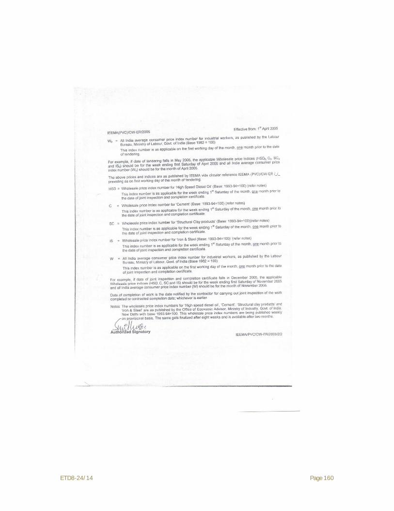
ETD8-24/14 Page 160

ETD8-24/14 Page 161
Part – III
Volume-I
Technical Condition of Contract
(Includes Technical Specification of Tower & its concerning Hardware & Accessories, Insulators etc.)

ETD8-24/14 Page 162
Part – III, Volume-I S. N. DESCRIPTION PAGE
1. Section-I – General Information & Scope 163-172
2. Section-II – General Technical Condition 173-182
3. Section-III – Survey & Soil Investigation 183-216
4. Section-IV – Tower Foundation , Erection, Stringing & Commissioning of Line 217-266
5. Section –V – Technical Description of Disc Insulators 267-293
6. Section –VI – Technical Description of Hardware Fittings, Conductor & Earthwire 294-371
7. Section –VII – Drawings (400 kV) 372-391

ETD8-24/14 Page 163
SECTION-I
GENERAL INFORMATION AND SCOPE

ETD8-24/14 Page 164
SECTION-I
TECHNICAL SPECIFICATIONS
1. General Information and Scope
1.1 Scope
1.1.1 The following 400 kV DC QUAD Transmission lines are included in the scope of the Contractor:-
S.N. Name of Line Double Circuit (Kms)
1- 400 kV DC Quad 765 kV Greater NOIDA to 400 kV Greater NOIDA Transmission Line 55
TOTAL 55 1.1.2 This Specification covers the following scope of works:
(i) Detailed survey including route alignment, profiling, tower spotting, optimisation of tower locations,
ii) Soil resistivity measurement & geotechnical investigation (excluding pile /well foundations)
(iii) Check survey; (iv) Fabrication and supply of all type of 400 kV transmission line towers, as per
Purchaser design/drawings including fasteners , anti-theft fasteners, step bolt, hangers, D-shackles etc.
(v) Supply of all types of tower accessories like phase plate, circuit plate, number plate, danger plate, anti-climbing device, Bird guard, pipe type and counterpoise type earthing.
(vi) Supply of Insulators and Hardware Fittings and Conductor & G S Earth wire Accessories,
(vii) Classification of foundation for different type of tower and casting of foundation for tower footings as per Purchaser foundations drawing (excluding well/pile foundation.
(viii) Erection of towers, tack welding of bolts and nuts including supply and application of zinc rich primer & two coats of enamel paint, tower earthing, fixing of insulator strings, stringing of conductors , earth wires and OPGW along with all necessary line accessories,
(ix) Painting of towers (above 45 meter height) and supply & erection of span markers, obstruction lights (wherever applicable) for aviation requirements (as required) as per IS 5613.
(x) Testing and commissioning of the erected transmission lines and (xi) Other items not specifically mentioned in this Specification but are required
for the successful commissioning of the transmission line, unless specifically excluded in the Specification.
1.1.2.1 Purchaser shall provide structural drawings, shop drawings & Bill of Materials of all type of transmission line towers and its extensions, to the Contractor after placement of award, in sequence, suiting the project requirement. Similarly the drawings for all

ETD8-24/14 Page 165
type of foundations for the towers shall also be provided by purchaser to the Contractor. The scope of this specification also provides for fabrication of prototype tower, its assembly and proto-inspection.
1.1.2.2 (a) The provisional quantities of fabricated & galvanized steel parts as per specifications required for towers, concrete, excavation volume & reinforcement steel for foundation and other items are given in appropriate price schedule. However, the work shall be executed as per approved construction drawings.
(b) The various items of work are described very briefly in the appropriate price schedule. The various items of the price schedule shall be read in conjunction with the corresponding sections in the Technical Specifications including amendments and, additions, if any. The Bidder’s quoted rates shall be based on the description of activities in the price schedule as well as other necessary operations required to complete the works detailed in these Technical Specifications.
(c) The Unit rates quoted shall include minor details which are obviously and fairly intended, and which may not have been included in these documents but are essential for the satisfactory completion of the various works.
(d) The unit rate quoted shall be inclusive of all plant equipment, men, material skilled and unskilled labour etc. essential for satisfactory completion of various works.
(e) All measurements for payment shall be in S.I. units, lengths shall be measured in meters corrected to two decimal places. Areas shall be computed in square meters & volume in cubic meters rounded off to two decimals.
1.1.2.3 The Bidder shall submit his offer taking into consideration that the tower and foundation designs/drawings shall be developed/provided by Purchaser and design rights will be strictly reserved with Purchaser. Bidder shall quote the unit rates for various items of towers and foundations as per units mentioned in appropriate price schedule. However, payment of these items identified in the schedule of prices shall be made as follows:
A) TOWER
i) Supply items i) On supply of respective complete stub alongwith cleats etc.
ii) On supply of respective complete tower ii) Erection items On erection of respective complete tower
B) Foundation items: On completion of respective foundation in all respect
The payment to be made for towers/foundations shall be worked out based on the unit rates and approved Bill of Materials (BOM) for towers and quantities/volumes as per approved tower foundation drawings.
1.1.3 This specification also includes the supply of insulators & hardware fittings and all type of accessories for conductor and earth wire as detailed in the specification. However hardware fittings and accessories of OPGW shall be arranged by the
ETD8-24/14 Page 166
purchaser. Contractor shall clearly indicate in their offer, the sources from where they propose to procure these materials. The technical descriptions of these items are given in Technical specification.
1.1.4 The Contractor shall take delivery of purchaser’s supplied material such as Conductor, GS earthwire, OPGW and hardware fittings & Accessories of OPGW at the stores established by the contractor in consultation with the Purchaser and ensure their safe custody and shall incorporate the same in the transmission lines as stipulated in this specification.
1.1.5 All the raw materials such as steel, zinc for galvanising, reinforcement steel, cement, coarse and fine aggregates for tower foundation, coke and salt for tower earthing etc. are included in the Contractor’s scope of supply.
1.1.6 Bidder shall also indicate in the offer, the sources from where they propose to procure the fasteners, anti-theft fasteners, step bolts, hangers, D-shackles etc., tower accessories, aviation signal (if required) etc.
1.1.7 Stringing
a) The entire stringing work of conductor and earth wire shall be carried out by tension stringing technique. However, the Bidder having requisite experience has freedom to use helicopter for stringing. The Bidder intending to use helicopter shall furnish detailed description of the procedure, type & number of helicopter & accessories etc., to be deployed for stringing operation.
b) In hilly terrain and thick forest or area with site constraints where deployment of tension stringing machine is not possible, manual stringing may be adopted after getting approval of supervising Engineer. The contractor shall deploy appropriate tools/equipments/machinery to ensure that the stringing operation is carried out without causing damage to conductor/earth wire/OPGW and conductor/earthwire/OPGW is installed at the prescribed sag-tension as per the approved stringing charts.
1.1.8 In case of special type pile or well foundations, some other party may be engaged by the purchaser for casting of foundations. However, the Bidder shall be responsible for all the necessary co-ordination with the special foundation Contractor including stub-setting/fixing of base plate with anchor bolt.
1.2 Details of Transmission Line Routes and Terrain
The detailed survey of lines, shall be carried out by the contractor. Final Tower schedule & profile of all the lines, covered under the specification as per Tower spotting data & sag template drawing provided by the purchaser shall be prepared by the contractor for approval of supervising Engineer. Erection works shall be carried out as per final profile of the lines approved by the supervising Engineer.
The detailed survey where ever required, shall be carried out using GPS, Total stations, digital theodolites etc. along the approved route alignment. As an alternative, the contractor may also use ALTM (Airborne Laser Terrain Modelling) techniques of equal or better accuracy for the detailed survey.

ETD8-24/14 Page 167
Bidders may visit the line route to acquaint themselves with terrain conditions and associated details of the proposed transmission lines.
1.3 Location Details and Terminal Points
1.3.1 The 400 kV Double Circuit (QUAD MOOSE) Transmission line shall emanate from existing 400 kV Greater NOIDA S/S (Pali) to 765 kV Greater NOIDA S/S (under construction). The Contractor shall have to construct these 400 kV Double Circuit (QUAD MOOSE) transmission lines completely up to dead end towers on either end. Stringing shall also be carried out from dead end tower to terminal arrangements/terminal points.
1.4 Access to the Line and Right of Way
Right of way and way leave clearance shall be arranged by the purchaser in accordance with work schedules. Purchaser will secure way leave and Right of way in the Forest area.
2.0 Transmission towers and Line data
2.1 General Description of the Tower
2.1.1 The transmission towers are of self-supporting hot dip galvanised lattice steel type designed to carry the line conductors with necessary insulators, earth wire/OPGW and all fittings under all loading conditions. Outline diagram of towers are enclosed with the Specification.
2.1.2 The tower shall be fully galvanised using mild steel or/and high tensile steel sections as specified in relevant clause in section-IV. Bolts and nuts with spring washer are to be used for connections.
2.1.3 The towers are of the following types:
400 kV Double Circuit (DA, DB, DC & DD) with Quad Conductor
2.2 Classification of Towers
2.2.1 The towers for 400 kV Lines are classified as given below:
Type of Tower
Deviation Limit
Typical Use
DA 0 deg i) To be used as tangent tower.
DB 0 deg - 15 deg i) Angle towers with tension insulator string.
ii) Also to be used for uplift force resulting from an uplift span upto 200 m under broken wire condition.
iii) Also to be used for Anti Cascading Condition.
DB 0 deg i) To be used as Section Tower.

ETD8-24/14 Page 168
Type of Tower
Deviation Limit
Typical Use
DC 15 deg-30 deg i) Angle tower with tension insulator string.
ii) Also to be used for uplift forces resulting from an uplift span upto 200 m under broken wire condition.
iii) Also to be used for anti cascading condition.
DC 0 deg i) To be used as section tower.
DD 30 deg-60 deg i) Angle tower with tension insulator string.
ii) Also to be used for uplift forces resulting from an uplift span upto 300 m under broken wire condition.
iii) for river crossing anchoring with longer wind span & 0 deg. Deviation on crossing span side and 0 deg. To 30 deg. Deviation on other side.
DD 0 deg. i) Dead end with 0 deg. To 15 deg. Deviation both on line side and sub-station side ( slack span)
Note: The above towers can also be used for longer span with smaller angle of deviations without infringement of ground clearance.
2.2.2 Transposition tower for 400 KV Lines
DC type towers (Section Towers) with suitable modifications are to be used for transposition of the line maintaining all the required clearance and shielding.
2.2.3 Extensions
2.2.3.1 The towers are designed so as to be suitable for adding 3M, 6M and 9M body extensions/leg extensions for maintaining adequate ground clearances without reducing the specified factor of safety in any manner.
2.2.3.2 The provision for addition of 18/25M body extension to tower types DA and DD for 400 KV lines is also kept by the Purchaser. For Power Line Crossing or any other obstacle, tower types DA or DD can be used with 18/25 M extensions depending, upon the merit of the prevailing site condition.
2.2.3.3 All above extension provisions to towers and foundations shall be treated as part of normal towers and foundations only.

ETD8-24/14 Page 169
2.3 Span and clearances 2.3.1 Normal Span The normal ruling span of the line is 400m. 2.3.2 Wind Span The wind span is the sum of the two half spans adjacent to the support under
consideration. For normal horizontal spans this equals to normal ruling span. 2.3.3 Weight span
The weight span is the horizontal distance between the lowest point of the conductors on the two spans adjacent to the tower. For spotting of structures, the span limits given in following table shall prevail:-
TOWER TYPE
NORMAL CONDITION
BROKENWIRE CONDITION
MAX (m) MIN (m) MAX (m) MIN (m)
DA 600 200 360 100
DB 600 0 360 (-) 200
DC 600 0 360 (-) 200
DD 600 0 360 (-) 300
2.4 Electrical Clearances 2.4.1 Ground Clearance The minimum ground clearance from the bottom conductor shall not be less than
8840 mm for 400KV lines at the maximum sag conditions i.e at 85° C and still air.
a) An allowance of 150mm shall be provided to account for errors in stringing. b) Conductor creep shall be compensated by over tensioning the conductor at a
temperature of 26°C lower than the stringing temperature for ACSR “MOOSE” conductor for 400 kV transmission lines.
2.5 Electrical System Data for 400 kV line
1. Nominal Voltage kV 400
2. Maximum system voltage kV 420
3. BIL (Impulse) kV (Peak) 1550
4. Power frequency withstand voltage (Wet) kV (rms) 680
5. Switching surge withstand voltage (Wet) kV (rms) 1050
6. Minimum Corona extinction voltage at 50 Hz AC system under dry condition
kV (rms) phase to earth
320(Min)
7. Radio interference voltage at one MHz for phase to earth voltage of 305 KV under dry condition.
Micro Volts 1000 (Max)

ETD8-24/14 Page 170
3.0 Details of line Material:
3.1 Conductor, Earthwire & OPGW for 400 kV line
Sl. No.
Description Conductor Earthwire OPGW (tentative)
1. Type ACSR ‘MOOSE’ conductor
7/3.66mm GS Earthwire
2. Stranding and wire dia
Aluminium 54/3.53 -
Steel 7/3.53 7/3.66
3. Conductor per phase 4 NA NA
4. Spacing between conductor of same phase (sub conductor spacing) (mm)
450 NA NA
5. Configuration Vertical
(for D/C with 8000 mm min.
inter phase spacing)
One continuously
to run horizontally on top of the towers and conductors.
One continuously
to run horizontally on top of the towers and conductors
6. Overall Diameter (mm)
31.77 10.98 ≈10.98
7. Unit mass (kg/km) 2004 583 ≈583
8. Min. UTS (kN) 161.6 68.4 ≈68.4
3.2 Insulator Strings
A Detail of Insulator String with Anti fog Disc Insulators for Normal Section
S N Particulars Double ‘I’ Suspension String
Single ‘I’ Suspension Pilot String
Single Tension String
Quadruple Tension String
1. Type of Disc Antifog Antifog Antifog Antifog

ETD8-24/14 Page 171
2. E& M strength of each insulator in the string in KN
120 120 120 160
3. No. of disc insulators per string
2×23 1×23 1×24 4 x 23
4. Size of disc in mm 280-305 x 145 280-305 x 145 280-305 x 145 305-320 x 170
5. Size and designation of pin ball in mm
20 20 20 20
6. Minimum creepage distance of each disc in mm
460 460 460 475
3.3 Insulator String Hardware (as may be applicable)
a) Anchor Shackle
b) Chain Link
c) Ball Clevis
d) Arcing horn holding plate
e) Yoke plate
f) Socket clevis
g) Arcing horns
h) Corona control ring/grading ring.
i) Clevis Eye
j) Free center type/Armour grip suspension clamp for suspension strings.
k) Compression type dead end clamp for tension string.
l) Sag adjuster for tension string.
m) Balancing weight for pilot string
3.4 Accessories for conductor & earth wire
a) Preformed Armour rods
b) Mid Span compression joint
c) Repair Sleeves
d) Flexible copper bonds

ETD8-24/14 Page 172
e) Spacer Dampers
f) Vibration dampers
g) Rigid Spacer
h) Suspension clamp for earth wire
i) Tension clamp for earth wire
4.0 Service Condition Equipment/material to be supplied against this specification shall be suitable for satisfactory continuous operation under conditions as specified below:
Maximum ambient temperature (Degree Celsius)
: 48
Minimum ambient temperature (Degree Celsius)
: 0
Relative humidity (% range) : 10-100
Maximum annual rainfall & snowfall (Cm)
: as per published Meteorological/ climatological data
Wind zone (as per IS: 875) : 4
Maximum wind velocity (m/sec.) : 47 m/sec. (as per IS : 875)
Maximum altitude above mean sea level (Metre)
: Below 1000 m
Isoceraunic level (days/years) : 50
Climate varies from moderately hot and humid tropical climate to cold climate.

ETD8-24/14 Page 173
SECTION-II
GENERAL TECHNICAL CONDITIONS

ETD8-24/14 Page 174
TECHNICAL SPECIFICATION
SECTION-II 1.0 General Technical Conditions 1.1 General The following provisions shall supplement all the detailed technical specifications
and requirements brought out herein. The contractor’s proposal shall be based on the use of materials complying fully with the requirements specified herein.
1.2 Engineering Data 1.2.1 The furnishing of engineering data by the Contractor shall be in accordance with
the Schedule as specified in the Bidding Document. The review of these data by the Purchaser will cover only general conformance of the data to the specifications and not a thorough review of all dimensions, quantities and details of the materials, or items indicated or the accuracy of the information submitted. This review by the Purchaser shall not be considered by the Contractor, as limiting any of his responsibilities and liabilities for mistakes and deviations from the requirements, specified under these specifications.
1.2.2 All engineering data submitted by the Contractor after review by the Purchaser shall form part of the contract document.
1.3 Drawings In addition to those stipulated in clause regarding drawings in GCC/SCC, the
following also shall apply in respect of Contractor Drawings. 1.3.1 All drawings submitted by the Contractor including those submitted at the time of
Bid shall be with sufficient detail to indicate the type, size, arrangement, dimensions, material description, Bill of Materials, weight of each component break-up for packing and shipment, fixing arrangement required, the dimensions required for installation and any other information specifically requested in these specifications.
1.3.2 Each drawing submitted by the Contractor shall be clearly marked with the name of the Purchaser, the specification title, the specification number and the name of the Project. All titles, noting, markings and writings on the drawing shall be in English. All the dimensions should be to the scale and in S.I. units.
1.3.3 The drawings submitted by the Contractor shall be reviewed by the Purchaser as far as practicable within 15 days and shall be modified by the Contractor if any modifications and/or corrections are required by the Purchaser. The Contractor shall incorporate such modifications and/or corrections and submit the final drawings for approval. Any delays arising out of failure by the Contractor to rectify the drawings in good time shall not alter the contract completion date.
1.3.4 The drawings submitted for approval to the Purchaser shall be in quadruplicate. One print of such drawings shall be returned to the Contractor by the Purchaser marked “approved/approved with corrections”. The contractor shall there upon furnish the Purchaser additional prints as may be required along with one reproducible in original of the drawings after incorporating all corrections.

ETD8-24/14 Page 175
1.3.5 The work shall be performed by the Contractor strictly in accordance with these drawings and no deviation shall be permitted without the written approval of the Purchaser, if so required.
1.3.6 All manufacturing, fabrication and erection work under the scope of Contractor, prior to the approval of the drawings shall be at the Contractor’s risk. The contractor may incorporate any changes in the design, which are necessary to conform to the provisions and intent of the contract and such changes will again be subject to approval by the Purchaser.
1.3.7 The approval of the documents and drawings by the Purchaser shall mean that the Purchaser is satisfied that:
(a) The Contractor has completed the part of the Works covered by the subject document (i.e. confirmation of progress of work).
(b) The Works appear to comply with requirements of Specifications. In no case the approval by the Purchaser of any document does imply compliance
with all technical requirements or the absence of errors in such documents. If errors are discovered any time during the validity of the contract, then the
Contractor shall be responsible for consequences. 1.3.8 All drawings shall be prepared using AutoCAD software version 2000 or later
only. Drawings, which are not compatible to AutoCAD software version 2000 or later, shall not be accepted. After final approval all the drawings (structural drawings, BOMs, shop sketches and tower accessories drawings) shall be submitted to the Purchaser in CDs.
A copy of each drawing reviewed will be returned to the Contractor as stipulated herein.
1.3.9 Copies of drawings returned to the Contractor will be in the form of a print with the Purchaser’s marking, or a print made from a microfilm of the marked up drawing.
1.3.10 The following is the general list of the documents and drawings that are to be approved by the Purchaser.
a) Work Schedule (Master Network) Plan. b) Detailed survey report and profile drawings showing ground clearance and
tower locations (as applicable). c) Tower schedule and foundation classification for individual tower locations. d) Soil Investigation report. e) Tower footing earthing drawing. f) Stringing procedure g) Tower accessories drawings like danger plate, name plate phase plate,
circuit plate, pipe and counter poise type earthing etc. h) Quality plans for fabrication and site activities including Quality System. i) Vendors approval, etc. j) Line material drawings. k) Type test report for line materials. 1.3.11 All rights of the design/drawing for all types of towers and foundations shall be
strictly reserved with the Purchaser only and any designs/drawings/data sheets submitted by the contractor from time to time shall become the property of the

ETD8-24/14 Page 176
Purchaser. Under no circumstances, the Contractor shall be allowed to use/offer above designs/drawings/data sheets to any other authority without prior written permission of the Purchaser. Any deviation to above is not acceptable and may be a cause for rejection of the bid.
1.4 Design Improvements 1.4.1 The Purchaser or the Contractor may propose changes in the specification and if
the parties agree upon any such changes and the cost implication, the specification shall be modified accordingly.
1.5 Design Co-ordination Wherever, the design is in the scope of Contractor, the Contractor shall be
responsible for the selection and design of appropriate material/item to provide the best coordinated performance of the entire system. The basic design requirements are detailed out in this Specification. The design of various components, sub-assemblies and assemblies shall be so done that it facilitates easy field assembly and maintenance.
1.6 Review Meeting The contractor will be called upon to attend review meetings with the Purchaser,
during the period of Contract. The contractor shall attend such meetings at his own cost at the Corporate Office of the Purchaser or at mutually agreed venue as and when required. Such review meeting will be held as and when required.
1.7 Quality Assurance, Inspection & Testing 1.7.1 Quality Assurance To ensure that the supply and services under the scope of this Contract whether
manufactured or performed within the Contractor’s works or at his Sub-Contractor’s premises or at site or at any other place of work are in accordance with the specifications. The Contractor shall adopt suitable quality assurance programme to control such activities at all points necessary. Such programme shall be broadly outlined by the Contractor and shall be finalised after discussions before the award of Contract. The detailed programme shall be submitted by the contractor after the award of contract and finally accepted by the Purchaser after discussion. A quality assurance programme of the Contractor shall generally cover but not limited to the following:
(a) His organization structure for the management and implementation of the proposed quality assurance programme.
(b) Documentation control System. (c) Qualification data for Contractor’s key personnel. (d) The procedure for purchase of materials, parts components and selection of
sub-Contractor’s services including vendor analysis, source inspection, incoming raw material inspection, verification of material purchases etc.
(e) System for shop manufacturing including process controls and fabrication and assembly controls.
(f) Control of non-conforming items and system for corrective action. (g) Control of calibration and testing of measuring and testing equipments. (h) Inspection and test procedure for manufacture.

ETD8-24/14 Page 177
(i) System for indication and appraisal of inspection status. (j) System for quality audits. (k) System for authorizing release of manufactured product to the Purchaser.
(l) System for maintenance of records. (m) System for handling storage and delivery and (n) A quality plan detailing out the specific quality control procedure adopted
for controlling the quality characteristics relevant to critical and important items of supply.
The Quality plan shall be mutually discussed and approved by the Purchaser after incorporating necessary corrections by the Contractor as may be required.
1.7.1.1 Quality Assurance Documents The Contractor shall be required to submit all the Quality Assurance Documents
as stipulated in the Quality Plan at the time of Purchaser's inspection of equipment/material.
1.7.1.2 The Purchaser or his duly authorized representatives reserves the right to carry out Quality Audit and quality surveillance of the systems and procedures of the Contractor's/his vendor's Quality Management and Control Activities.
1.7.2 Purchaser’s Supervision 1.7.2.1 To eliminate delays and avoid disputes and litigation to the Contract, all matters
and questions shall be resolved in accordance with the provisions of this document.
1.7.2.2 The manufacturing of the product shall be carried out in accordance with the specifications. The scope of the duties of the Purchaser, pursuant to the contract, will include but not be limited to the following.
a) Interpretation of all the terms and conditions of these Documents and Specifications.
b) Review and interpretation of all the Contractor's drawings, engineering data etc.
c) Witness or authorize his representative to witness tests at the manufacturer's works or at site, or at any place where work is performed under the contract.
d) Inspect, accept or reject any equipment, material and work under the Contract, in accordance with the Specifications.
e) Issue certificate of acceptance and/or progressive payment and final payment certificate.
f) Review and suggest modification and improvement in completion schedules from time to time, and
g) Supervise the Quality Assurance Programme implementation at all stages of the works.
1.8 Inspection and Tests 1.8.1 Inspection 1.8.1.1 The Purchaser, his duly authorized representative and/or outside inspection
agency acting on behalf of the Purchaser shall have, at all reasonable times,
access to the premises and /or works of the contractor and/or their sub-

ETD8-24/14 Page 178
contractor(s)/sub-vendors and shall have the right, at all reasonable times, to
inspect and examine the materials and workmanship of the product during its
manufacture.
1.8.1.2 The Contractor shall give the Purchaser’s Inspector fifteen (15) days (in case of
domestic testing and thirty (30) days (in case of foreign testing), as the case may
be, written notice of any material being ready for testing. In case of turnkey
contract, the turnkey contractor shall give the notice for inspection and shall
associate in the inspection with Employee’s inspector. All such inspections shall
be to the Contractor's account except for the expenses of the Purchaser’s
inspector. The Purchaser’s inspector, unless witnessing of the tests is virtually
waived, will attend such tests within fifteen (15) days (in case of domestic
testing) and thirty (30) days in (in case of foreign testing) of the date of which the
equipment is notified as being ready for test/inspection or on a mutually agreed
date, failing which the Contractor may proceed with the test in accordance with
the technical specification after informing the Purchaser’s in writing and he shall
forthwith forward to the inspector duly certified copies of test reports / certificates
in triplicate.
1.8.1.3 The Purchaser’s Inspector shall, within fifteen (15) days from the date of
inspection, give notice in writing to the Contractor, of any objection to any
drawings and all or any equipment and workmanship which in his opinion is not
in accordance with the Contract. The Contractor shall give due consideration to
such objections and shall make the modifications that may be necessary to meet
the said objections.
1.8.1.4 When the factory tests have been completed at the Contractor’s or Sub-
Contractor’s works, the Purchaser’s inspector shall issue a certificate to this
effect within fifteen (15) days after completion of tests but if the tests are not
witnessed by the Purchaser’s inspector, the certificate shall be issued within
fifteen (15) days of receipt of the Contractor’s Test Certificate by the Purchaser’
Inspector. The completion of these tests or the issue of the certificate shall not
bind the Purchaser’s to accept the equipment should it, on further tests after
erection, be found not to comply with the Contract.
1.8.1.5 In all cases where the Contract provides for test whether at the premises or works
of, the Contractor or of any Sub-Contractor, the Contractor except where
otherwise specified shall provide free of charge such item as labour, materials,

ETD8-24/14 Page 179
electricity, fuel, water, stores. apparatus and instruments as may be reasonably
demanded by the Purchaser’s inspector or his authorised representative to carry
out effectively such tests of the equipment in accordance with the Contract and
shall give facilities to the Purchaser’s Inspector or to his authorised
representative to accomplish testing.
1.8.1.6 The inspection by Purchaser and issue of Inspection Certificate thereon shall in
no way limit the liabilities and responsibilities of the Contractor in respect of the
agreed Quality Assurance Programme forming a part of the Contract.
1.8.1.7 a) The Contractor shall keep the Purchaser informed in advance about the
time of starting and of the progress of manufacture and fabrication of
various tower parts at various stages, so that arrangements could be made
for inspection.
b) The acceptance of any part of items shall in no way relieve the Contractor
of any part of his responsibility for meeting all the requirements of the
Specification.
1.8.1.8 The Purchaser or his representative shall have free access at all reasonable times
to those parts of the Contractor’s works which are concerned with the fabrication
of the Purchaser’s material for satisfying himself that the fabrication is being
done in accordance with the provisions of the Specification.
1.8.1.9 Unless specified otherwise, inspection shall be made at the place of manufacture
prior to dispatch and shall be concluded so as not to interfere unnecessarily with
the operation of the work.
1.8.1.10 Should any member of the structure be found not to comply with the supplied
design, it shall be liable to rejection. No member once rejected shall be
resubmitted for inspection, except in cases where the Purchaser or his authorized
representative considers that the defects can be rectified.
1.8.1.11 Defect which may appear during fabrication shall be made good with the consent
of, and according to the procedure proposed by the Contractor and approved by
the Purchaser.
1.8.1.12 All gauges and templates necessary to satisfy the Purchaser shall be supplied by
the contractor.
1.8.1.13 The specified grade and quality of steel shall be used by the Contractor. To ascertain
the quality of steel used, the inspector may at his discretion get the material tested at
an approved laboratory.

ETD8-24/14 Page 180
1.8.2 Tests
1.8.2.1 The type, acceptance and routine tests and tests during manufacture shall be
carried-out on the material and shall mean as follows:
1.8.2.1.1 Type Tests shall mean those tests which are to be carried out to prove the process
of manufacture and general conformity of the material to this Specification. These
tests shall be carried out on samples prior to commencement of commercial
production against the order.
1.8.2.1.2 Acceptance Tests shall mean those tests which are to be carried out on samples
taken from each lot offered for pre-dispatch inspection, for the purposes of
acceptance of that lot.
1.8.2.1.3 Routine Tests shall mean those tests, which are to be carried out on the material
to check requirements which are likely to vary during production.
1.8.2.1.4 Tests During Manufacture shall mean those tests, which are to be
carried out during the process of manufacture and end inspection by the
Contractor to ensure the desired quality of the end product to be supplied by him.
1.8.2.2 The norms and procedure of sampling for these tests will be as per the Quality
Assurance Programme to be mutually agreed to by the Contractor and the
Purchaser.
1.8.2.3 The standards and norms to which these tests will be carried out are listed against
them. Where a particular test is a specific requirement of this Specification, the
norms and procedure of the test shall be as specified in Annexure-A or as
mutually agreed to between the Contractor and the Purchaser in the Quality
Assurance Programme.
1.8.2.4 For all type and acceptance tests, the acceptance values shall be the values
specified in this Specification or guaranteed by the Bidder, as applicable.
1.9 Standard Technical Particulars 1.9.1 The Standard Technical Particulars of the various items are given in the relevant
schedule of the specification. The bidder is required to comply with the same. 1.10 Packing 1.10.1 All the materials shall be suitably protected, coated, covered or boxed and crated
to prevent damage or deterioration during transit, handling and storage at Site till
the time of erection. The Contractor shall be responsible for any loss or damage
during transportation, handling and storage due to improper packing.
1.10.2 The Contractor shall include and provide for securely protecting and packing the
materials so as to avoid loss or damage during transport by air, sea, rail and road.

ETD8-24/14 Page 181
1.10.3 All packing shall allow for easy removal and checking at site. Wherever
necessary, proper arrangement for attaching slings for lifting shall be provided.
All packages shall be clearly marked for with signs showing ‘up’ and ‘down’ on
the sides of boxes, and handling and unpacking instructions as considered
necessary. Special precaution shall be taken to prevent rusting of steel and iron
parts during transit by sea.
1.10.4 The cases containing easily damageable material shall be very carefully packed
and marked with appropriate caution symbols, i.e. fragile, handle with care, use
no hook etc. wherever applicable.
1.10.5 Each package shall be legibly marked by the Contractor at his expenses showing
the details such as description and quantity of contents, the name of the consignee
and address, the gross and net weights of the package, the name of the Contractor
etc.
1.10.6 Angle section shall be wire bundled. 1.10.7 Cleat angles, gusset plates, brackets, fillet plate, hanger and similar loose pieces
shall be tested and bolted together in multiples or securely wired through holes.
1.10.8 Bolts, nuts washers and other attachments shall be packed in double gunny bags
accurately tagged in accordance with the contents.
1.10.9 The packing shall be properly done to avoid losses & damages during transit.
Each bundle or package shall be appropriately marked.
2.0 Purchaser’s Environment and Social Policy and its Implementation 2.1 Development and growth of mankind through Industrialization and unwarranted
use of natural resources has inflicted considerable impact on Environment and
Society. As a result, Environmental and Social issues have emerged as the focal
point of global debate.
Purchaser’s activities by their inherent nature and flexibility have negligible
impacts on environmental and social attributes. In order to address these issues
and to match the rising expectations of a cleaner, safer and healthier environment,
Purchaser has evolved its Environmental and Social Policy and Procedures
(ESPP). The key principles of Purchaser’s Environmental and Social Policy are :
i) Avoidance of environmentally and socially sensitive areas while planning project activities.
ii) Minimisation of impacts when project activities occur in environmentally and socially sensitive areas.
iii) Mitigation of any unavoidable adverse impacts arising out of its projects.
ETD8-24/14 Page 182
2.2 Basic issues to be kept in mind while carrying out construction activities are to:
i) Avoid socially sensitive areas with regard to human habitations and areas of
cultural significance.
ii) Secure the interest of people affected by Purchaser’s projects.
iii) Involve local people affected by transmission line projects as per
requirement and suitability.
iv) Consult affected people in decisions having implication to them if
considered necessary.
v) Apply, efficient and safe technology/practices.
vi) Keep abreast of all potential dangers to people’s health, occupational safety
and safety of environment and the respective mitigatory measures.
vii) Establish preventive mechanisms to guarantee safety.
viii) Mitigation measures in case of accidents.
ix) Avoid unwarranted cutting of trees in forest area.
2.3 While constructing the lines through forest stretches the contractor will provide
alternate fuel to its employee e.g. working labours/supervisors etc. in order to
avoid cutting of forest woods.
2.4 Contractor will ensure safety to the wild life, during working/camping near to the
National park.
2.5 Contractor during construction of lines in agricultural fields will ensure minimum
damages to the crops, trees, bunds, irrigation etc. If the same is un-avoidable, the
decision of Engineer- in-charge shall be final.
2.6 The waste/excess material/debris should be removed from the construction site
including agricultural field, forest stretches, river etc. immediately after
construction work.
2.7 The Contractor will ensure least disturbance to the hill slope and natural drainage so
as to avoid soil erosion. Natural drainage in plain area if disturbed is to be trained
to the satisfaction of Engineer- in-charge.
2.8 As far as possible existing path/kutchcha road/approach shall be used for the
construction.
2.9 The Contractor will ensure supply of stone chips/sand from authorized/approved
quarry areas.
2.10 Proper documentation of above, if any.

ETD8-24/14 Page 183
SECTION-III
SURVEY & SOIL INVESTIGATION

ETD8-24/14 Page 184
SURVEY

ETD8-24/14 Page 185
TECHNICAL SPECIFICATION
(SECTION – III)
SURVEY & SOIL INVESTIGATION
1. General Information & Scope Of Work
1.1 The technical specifications covers detailed survey including route alignment, profiling, tower spotting, optimization of locations, check survey, contouring, and soil investigation for the transmission lines / part of the transmission lines covered under this specification.
1.1.1 The scope of work inter-alia shall include the following:- a. Detailed Survey using GPS, Total Work stations, long range scanners &
Digital theodolites of reasonable accuracies or alternatively using ALTM (Airborne Laser Terrain Modeling) techniques, inter-alia including :
i. Digitised profiling along the selected route along with plan details.
ii. Computer aided tower spotting & optimization
iii. Soil resistivity measurement along the route
b. Check survey including digitised contouring at undulated / hilly tower locations.
c. Soil Investigation
d. Preparation of Survey reports including estimation of Bill of Quantities, identification and explanation of route constraints (like Forest, Animal/Bird sanctuary, reserve coal belt areas, oil pipe line/underground inflammable pipe lines etc.), infrastructure details available en-route etc.
e. Wherever, the scope of work is only for part of the line for route changes if any necessitated during execution on account of site constraints and done at the instance of Purchaser and where survey data for balance stretches have been provided by the Purchaser, the Contractor may use the data already provided by the Purchaser to the extent applicable.
1.2 The Provisional quantities for the scope of work are indicated in relevant Price Schedules. The final quantities for route alignment & detailed survey (quantities in “kms” unit) shall be the route length along the approved route alignment. For contouring at undulated/hilly tower locations and soil investigations (quantities in “Locs.” unit), the actual quantities to be executed shall be decided by Supervising Engineer during execution stage and the final quantities shall be as approved by Supervising Engineer. The route alignment, detailed survey, including profiling & tower spotting, contouring, soil investigation etc shall be carried out by the Contractor as per the technical specifications stipulated herein.
1.3 The Contractor must note that the Purchaser shall not be responsible for loss or damage to properties, trees etc. due to contractor’s work during survey. The Contractor shall indemnify the Purchaser for any loss or damage to properties, trees etc. during the survey work.
ETD8-24/14 Page 186
1.4 The Contractor should note that Purchaser will not furnish the NRSA satellite imageries or topographical maps prepared by survey of India but will make available assistance that may be required in obtaining these by providing letters of recommendation to the concerned authorities. Further, in case the contractor opts for use of ALTM techniques for detailed survey, he shall be responsible for obtaining necessary clearances/permissions, as may be required from concerned authorities. The Purchaser will provide assistance that may be required in obtaining these clearances / permissions by providing letters of recommendation to the concerned authorities.
1.5 The work shall be carried out by the contractor using modern surveying techniques. The bidder shall indicate in his offer, the detailed description of the procedure to be deployed. The details of the equipment & facilities including soft wares for image processing, computer aided tower spotting etc. available with the bidder or his associates shall also be furnished with the bid.
1.6 The Contractor shall also engage services of a reputed geo-technical consultant or experts from independent educational/research institutions for examining stability aspects of the selected transmission line route/locations in hilly terrain wherever required.
1.7 After carrying out the detailed survey and soil investigations, the contractor shall estimate complete BOQ of the transmission lines and submit the same (as per the BOQ format enclosed with the Technical Specifications) to the Purchaser.
2. Route Alignment
2.1 Route Alignment shall be carried out for the line using satellite imageries of NRSA (PAN & LISS-III merged product) and Survey of India topographical maps (scale 1:50000), any changes necessitated during execution stage in the route alignment, same shall be carried out by the contractor using satellite imageries / topographical maps.
2.2 Requirement of Transmission Line Routing (for changes if any necessitated on account of site constrains etc.):
2.2.1. The Routing of the transmission line shall be most economical from the point of view of construction and maintenance. The contractor shall identify & examine alternative route alignments and suggest to the Purchaser the optimal route alignment.
2.2.2. Routing/Re-routing of transmission line through protected/reserved forest area should be avoided. In case it is not possible to avoid the forests or areas having large trees completely, then keeping in view of the overall economy, the route should be aligned in such a way that cutting of trees is minimum.
2.2.3. The route should have minimum crossings of Major river, Railway lines, National/State highways, overhead EHV power line and communication lines.
2.2.4. The number of angle points shall be kept to minimum.

ETD8-24/14 Page 187
2.2.5. The distance between the terminal points specified shall be kept shortest possible, consistent with the terrain that is encountered.
2.2.6. Marshy and low lying areas, river beds and earth slip zones shall be avoided to minimize risk to the foundations.
2.2.7. It would be preferable to utilize level ground for the alignment.
2.2.8. Crossing of power lines shall be minimum. Alignment will be kept at a minimum distance of 300 m from power lines to avoid induction problems on the lower voltage lines.
2.2.9. Crossing of communication line shall be minimized and it shall be preferably at right angle. Proximity and parallelism with telecom lines shall be eliminated to avoid danger of induction to them.
2.2.10. Areas subjected to flooding such as nalah shall be avoided.
2.2.11. Restricted areas such as civil and military airfield shall be avoided. Care shall also be taken to avoid aircraft landing approaches.
2.2.12. All alignment should be easily accessible both in dry and rainy seasons to enable maintenance throughout the year.
2.2.13. Certain areas such as quarry sites, tea, tobacco and saffron fields and rich plantations, gardens & nurseries which will present the Purchaser problems in acquisition of right of way and way leave clearance during construction and maintenance should be avoided.
2.2.14. Angle points should be selected such that shifting of the point within 100 m radius is possible at the time of construction of the line.
2.2.15. The line routing should avoid large habitations, densely populated areas, Forest, Animal/Bird sanctuary, reserve coal belt areas, oil pipe line/underground inflammable pipe lines etc. to the extent possible.
2.2.16. The areas requiring special foundations and those prone to flooding should be avoided.
2.3 For examination of the alternatives & identification of the most appropriate route, besides making use of information/data/details available/extracted through Survey of India Topographical maps and computer-aided processing of NRSA’s satellite imagery, the contractor shall also carryout reconnaissance/preliminary survey as may be required for verification & collection of additional information /data /details.
2.4 The contractor shall submit his preliminary observations & suggestions along with various information/data /details collected and also processed satellite imagery data, scanned topographical map data marked with the alternative routes etc. The final evaluation of the alternative routes shall be conducted by the contractor in consultation with Purchaser’s representatives and optimal route alignment shall be proposed by the contractor. Digital terrain modelling using contour data from topographical maps as well as processed satellite data shall be done by the contractor for the selected route. A fly through perspective using suitable software(s) shall be developed for further refinement of the selected route, if

ETD8-24/14 Page 188
required. Site visit and field verification shall be conducted by the contractor jointly with the Purchaser’s representative for the proposed route alignment.
2.5 Final digitized route alignment drawing with latest topographical and other details/features including all rivers, railway lines, canals, roads etc. up to 8 kms on both sides of selected route alignment shall be submitted by the contractor for approval of Supervising Engineer along with report containing other information/details as mentioned above.
2.6 Changes in the route alignment, if any, during detail survey, shall be incorporated in the final digitized route alignment drawings.
3. Detailed Survey
3.1 The detailed survey shall be carried out using DGPS, Total stations, digital theodolites etc. along the approved route alignment. As an alternative, the contractor may also use ALTM (Airborne Laser Terrain Modeling) techniques of equal or better accuracy for the detailed survey.
3.2 Soil resistivity, along the route alignment shall be measured in dry weather by four electrode method keeping inter-electrode spacing of 50 mtrs. For calculating soil resistivity formula 2ar (Where a=50 m and r = megger reading in ohms) shall be adopted. Measurement shall be made at every 2 to 3 km along the length of the route. In case soil characteristics changes within 2 to 3 km, values shall have to be measured at intermediate locations also. Megger reading and soil characteristics should also be indicated in the soil resistivity results.
3.3 Route Marking
3.3.1. The route of the transmission line shall be recorded using GPS/DGPS of positional accuracy less than 3m.
3.3.2. The co-ordinates of all the angle points as well as other important crossings, landmarks etc. shall be recorded using GPS for easy relocating.
3.3.3. At the starting point of the commencement of route survey the co-ordinates shall be recorded. A punch mark on the top section of the angle iron shall be made to indicate location of survey instrument. The co-ordinates of the location of the survey instrument shall also be recorded. Further, the co-ordinates at prominent position at intervals of not more than 750 meter along the transmission line to be surveyed up to the next angle point shall also be recorded. Wooden peg 50 x 50 x 650 mm size shall also be driven at prominent position at intervals of not more than 750 meters along the transmission line to be surveyed up to next angle point. Wire nails of 100 mm length should be fixed on the top of these pegs to show the location of instrument. The pegs shall be driven firmly into the ground to project 100mm only above the ground level. Wherever the line alignment crosses the EHT line, Railway line, P&T line or roads, the contractor shall record co-ordinates on the points of crossing. Wherever line route alignment passes over permanent land marks such as rock, boulders, culverts etc. suitable white paint marks with directional and Owner markings shall be made and co-ordinates recorded. At angle position stone / concrete pillars of 150 x 150 x 1000 mm in size with UPPTCL marked on them shall be embedded into the ground for easy identification.
ETD8-24/14 Page 189
3.4 Profiling
3.4.1. The complete profiling along the route shall be carried out using modern surveying equipments viz. total stations, DGPS, digital theodolite, long range scanners etc. Reference levels at every 20 metres along the route are to be recorded. R/Ls at other undulations along the route as well as in the route plan and other enroute details viz. crossings, building & structures, trees & other infrastructure etc. shall also be recorded. Areas along the route, which in the view of the contractor, are not suitable for tower spotting, shall also be marked.
3.4.2. The complete profiling details shall be digitized and the data shall be prepared & stored in the format compatible to computer-aided tower spotting software.
A printed/plotted output of the digitized profiling shall be submitted by the contractor to Purchaser’s Supervising Engineer for review before taking up computer-aided tower spotting.
3.5 Optimisation of Tower Location / Tower Spotting
3.5.1. Optimisation of tower locations shall be done by the contractor using computer-aided tower spotting software - PLSCADD and shall furnish sample calculations and manual tower spotting drawings for some typical sections.
3.5.2. The sag-tension characteristics of the conductor as well as tower spotting data and sag template curve shall be furnished by the Purchaser to the contractor.
3.5.3. General description of towers is indicated in Section–I of this specification for information of the Bidders.
3.5.4. Tower Spotting
While profiling & spotting the towers, the following shall be borne in mind:
a) Span The number of consecutive spans between the section points shall not exceed 15 spans or 5 Km in plain terrain and 10 spans or 3km in hilly terrain. A section point shall comprise of tension point with DB type or DC type or DD type towers as applicable. b) Extension/Truncation An individual span shall be as near to the normal design span as possible. In case an individual span becomes too short with normal supports on account of undulations in ground profile, one or both the supports of the span may be extended by inserting standard body/leg extension. In case of locations where the ground clearance is available, truncated towers may be spotted. The provisions kept in the design of towers w.r.t. body/leg extns, truncations shall be intimated to the contractor by the Purchaser during execution stage. c) Loading There shall not be any upward force on suspension towers under normal working conditions and the suspension towers shall support at least the minimum weight span as provided in the designs. In case uplift is unavoidable, it shall be examined if the same can be overcome by adding standard body extensions to the towers

ETD8-24/14 Page 190
failing which tension towers designed for the purpose shall be deployed at such positions. d) Road Crossing At all important road crossings, the tower shall be fitted with tension insulator strings but the ground clearance at the roads under maximum temperature and in still air shall be such that even with conductor broken in adjacent span, ground clearance of the conductor from the road surfaces will not be less than specified minimum ground clearance. At all national highways DD type towers with double tension insulator string shall be used and crossing span will not be more than 250 meters. e) Railway Crossings All the railway crossings coming-enroute the transmission line shall be identified by the Contractor. At the time of detailed survey, the railway crossings shall be finalised as per the regulation laid down by the Railway Authorities. The following are the important features of the prevailing regulations (revised in 1987) i) The crossings shall be supported on DD type tower on either side depending
on the merits of each case.
ii) The crossing shall normally be at right angle to the railway track.
iii) The minimum distance of the crossing tower shall be at least equal to the height of the tower plus 6 meters away measured from the centre of the nearest railway track.
iv) No crossing shall be located over a booster transformer, traction switching station, traction sub-station or a track cabin location in an electrified area.
v) Minimum ground clearance above rail level of the lowest portion of any conductor under condition of maximum sag shall be maintained at 17.90 m for 400 kV transmission lines.
vi) The crossing span will be limited to 300 meters.
f) River Crossings
In case of major river crossing, towers shall be of suspension type along with anchor towers of DD type tower on either side of the main river crossing. Alternately on the basis of economics and/ or site/ execution constraints crossing of rivers using extended angle towers also shall be considered. For navigable rivers, clearance required by navigation authority shall be provided. For non navigable river, clearance shall be reckoned with respect to highest flood level (HFL).
g) Power line Crossings
Where the line is to cross over another line of 132 kV or above voltage DD type tower with suitable extensions shall be used depending upon merit of the prevailing site condition. For line crossings of lower than 132 kV level suspension / tension tower with suitable extension may be used depending upon merit of the prevailing site condition. Provisions to prevent the possibility of its coming

ETD8-24/14 Page 191
into contact with other overhead lines shall be made in accordance with the Indian Electricity Rules, 1956 as amended up-to-date. In order to reduce the height of the crossing towers, it may be advantageous to remove the ground-wire of the line to be crossed (if this is possible and permitted by the Purchaser of the line to be crossed).
Minimum clearance in meters between lines when crossing each other:
Sl. No. Nominal System Voltage 110-132KV 220KV 400KV 765KV
1. 110-132KV 3.05 4.58 5.49 7.94
2. 220KV 4.58 4.58 5.49 7.94
3. 400KV 5.49 5.49 5.49 7.94
4. 765KV 7.94 7.94 7.94 7.94
h) Telecommunication Line Crossings
The angle of crossing shall be as near to 90 degree possible. However, deviation to the extent of 30 degree may be permitted under exceptionally difficult situations.
When the angle of crossing has to be below 60 degree, the matter will be referred to the authority in charge of the telecommunication System. On a request from the Contractor, the permission of the telecommunication authority may be obtained by the Purchaser.
Also, in the crossing span, power line support will be as near the telecommunication line as possible, to obtain increased vertical clearance between the wires.
i) Details En-route
All topographical details, permanent features, such as trees, building etc. 23 m for 400 KV line on either side of the alignment shall be detailed on the profile plan.
3.6 Clearance from Ground, Building, Trees etc.
Clearance from ground, buildings, trees and telephone lines shall be provided in conformity with the Indian Electricity Rules, 1956 as amended upto date.
The Contractor shall count, mark and put proper numbers with suitable quality of paint at his own cost on all the trees that are to be cut by the Purchaser at the time of actual execution of the work as detailed below. Contractor may please note that Purchaser shall not pay any compensation for any loss or damage to the properties or for tree cutting due to Contractor’s work.

ETD8-24/14 Page 192
3.6.1. To evaluate and tabulate the trees and bushes coming within 23 m for 400 KV line on either side of the central line alignment the trees will be numbered and marked with quality paint serially from angle point 1 (I) onwards and the corresponding number will be painted on the stem of trees at a height of 1 meter from ground level. The trees list should contain the following:
a) Girth (circumstances) measured at a height of 1 meter from ground level.
b) Approximate height of the tree with an accuracy of +2 meters.
c) Name of the type of the species/tree.
d) The bushy and under growth encountered within the 46 m for 400 kV line should also be evaluated with its type, height, girth and area in square meters, clearly indicating the growth in the tree/bush statement.
3.6.2. The contractor shall also intimate the Purchaser his assessment about the likely amount of tree & crop compensation etc. required to be paid by the Purchaser during execution stage. This assessment shall be done considering prevailing practices/guidelines, local regulations and other enquiries from local authorities.
3.6.3. The Contractor shall also identify the forest/non forest areas involved duly authenticated by concerned authorities.
a) A statement of forest areas with survey/compartment Nos.(all type of forest RF/PF/Acquired forest/Revenue forest/Private forest/Forest as per dictionary meaning of forest etc.)
b) A statement of non-forest areas with survey/compartment nos.
c) Tree cutting details(Girth wise & specie wise)
d) Marking of forest areas with category on topo sheets 1:2,50,000 showing complete line route, boundaries of various forest divisions and their areas involved.
e) Village forest maps of affected line and affected forest area and marking of the same.
f) Forest division map showing line and affected forest area.
3.6.5 The Contractor shall finalize the forest clearance proposal on the prescribed format as per requirements of the state/MOE&F, duly completed in all respects for submission by the Purchaser to the Forest Department.
3.7 Preliminary Schedule
The profile sheets showing the locations of the towers together with preliminary schedules of quantities indicating tower types, wind & weight spans, angle of deviation, crossing & other details etc. shall be submitted by the contractor for review & approval by supervising engineer.

ETD8-24/14 Page 193
3.8 Check Survey of Tower Locations
3.8.1. The check survey shall be conducted to locate tower locations on ground conforming to the approved profile and tower schedule.
3.8.2. The co-ordinates of all the tower locations shall also be recorded using GPS/DGPS of positional accuracy less than 3m for easy relocating. The position of all tower locations shall be marked in the final digitized route alignment drawing with relative distances from any permanent bench mark area.
3.8.3. The contractor shall also collect required data at each tower location in respect of soil strata, ground water level, history of water table in adjacent areas/surface water, distance from permanent bench mark (these details to be furnished in a tabulated form) and classify the suitable type of foundation at each tower location based on the data collected at each location and detailed soil investigations carried out at selected locations etc.
3.9 Contouring at hilly/undulated locations
3.9.1. The levels up or down of each pit centre with respect to centre of tower location shall be recorded at intervals of 2m using total stations/GPS/digital theodolite and digitized contour plans shall be made. Based on the digitized elevation plans, the quantities of benching & protection work vis-à-vis possible unequal leg extensions shall be optimized using suitable computer-aided techniques/software. Required tower and foundation details, cost data for comparative evaluation for benching & protection work vis-à-vis unequal leg extensions shall be provided by the Purchaser to the Contractor during execution stage.
3.10 The changes desired by the Purchaser in the preliminary tower schedule or as may be required based on detailed survey of tower locations & contouring by the contractor, shall be carried out by the contractor and the final tower schedule shall be submitted for approval of Purchaser. The tower schedule shall show position of all type of towers, span length, type of foundation for each tower, benching & revetment requirement, unequal leg extensions, deviation at all angles, crossings & other details etc.
3.11 Survey Methodology & Precision
3.11.1. All elevations shall be referenced to benchmarks established by the survey of India. Survey operations shall begin and end at benchmarks approved by the Purchaser.
3.11.2. During the levelling of the profile, check surveys will be effected at intervals not exceeding 50 Kms. with benchmarks of known elevations. The difference in elevations as surveyed by the contractor and as declared by Survey of India for these benchmarks shall not exceed the precision required for 3rd order surveys e ≤ 24k where k is the distance between benchmarks in km and e is the difference between elevations in mm.
3.11.3. In the absence of suitable benchmarks the levelling shall be done by two independent levelling parties working in opposite directions along the same line. The difference in elevations between the two surveys shall not exceed the precision required for 3rd order surveys as stated above.
ETD8-24/14 Page 194
3.11.4. All important objects and features along the transmission line centreline (railways, highways, roads, canals, rivers, transmission lines, distribution lines, telephone lines etc.) shall be surveyed and located with a positional accuracy of 1:2000 between points of known horizontal position.
3.12 Survey Report
3.12.1. Complete BOQ of the transmission lines as per format enclosed with this technical specification at Annexure-A shall be furnished in the survey report.
3.12.2. Each angle point locations shall be shown with detailed sketches showing existing close by permanent land marks such as specific tree(s), cattle shed, homes, tube wells, temples, electric pole/tower, telephone pole, canal, roads, railway lines etc. The relative distance of land marks from the angle points and their bearings shall be indicated in the sketch. These details shall be included in the survey report.
3.12.3. Information w.r.t infrastructure details available en-route, identification and explanation of route constraints, etc. shall also be furnished in the Survey report and shall inter-alia include the following:
3.12.3.1. Information regarding infrastructural facilities available along the final route alignment like access to roads, railway stations, construction material sources (like quarry points for stone, sand and availability of construction water), labour, existing transport facilities, fuel availability etc. shall be furnished in the survey report.
3.12.3.2. All observations which the Contractor thinks would be useful to the construction of the transmission lines mentioned under scope of work are to be reported.
3.12.3.3. Suggestions regarding the number of convenient zones (line segments / portions) in which the entire alignment can be divided keeping in view the convenience of corporation are to be given.
3.12.3.4. Suggestions regarding location for setting up stores during line construction in consultation with Purchaser’s representative shall also be provided by the contractor.
3.12.3.5. Working months available during various seasons along the final route alignment, with period, time of sowing & harvesting of different type of crops and the importance attached to the crops particularly in the context of way leave problems and compensation payable shall be stated by the Contractor.
3.12.3.6. Availability of labour of various categories and contractors of civil works shall also be reported.
3.12.3.7. Some portions of the line may require clearance from various authorities. The Contractor shall indicate the portion of the line so affected, the nature of clearance required and the name of concerned organizations such as local bodies, municipalities, P&T (name of circle), Inland navigation, Irrigation Department, Electricity Boards and Zonal railways, Divisional Forest Authorities etc.
3.12.4. All the requisite data for processing the case for statutory clearances such as PTCC, Forest and Railway shall be provided along with the report.
3.12.5. Six copies of survey reports shall be furnished by the contractor to the Purchaser.

ETD8-24/14 Page 195
4. Geotechnical Investigations
4.1 General
4.1.1. Purchaser requires that a detailed Geotechnical investigation be carried out at various tower locations to provide the designer with sufficiently accurate information, both general and specific, about the substrata profile and relevant soil and rock parameters at site on the basis of which the foundation of transmission line towers can be classified and designed rationally.
4.1.2. These specifications provide general guidelines for geotechnical investigation of normal soils. Cases of marshy locations and locations affected by salt water or saltpetre shall be treated as special locations and the corresponding description in these specifications shall apply. Any other information required for such locations shall be obtained by Contractor and furnished to Purchaser.
4.2 Scope
4.2.1. The scope of work includes detail soil investigations and furnishing bore log data at various tower locations. The provisional quantities have been indicated in Bill of Quantities. However, during actual execution of work, the quantities shall be decided by the Engineer - in - Charge, depending upon the soil strata and terrain. Based on the bore log data / soil parameter /soil investigation results, the Contractor shall recommend the type of foundations suitable for each locations and the same shall be got approved by the Purchaser.
4.2.2. These specifications cover the technical requirements for a detailed Geotechnical investigation and submission of a detailed Geotechnical Report. The work shall include mobilization of all necessary tools and equipment, provision of necessary engineering supervision and technical personnel, skilled and unskilled labour, etc. as required to carry out the entire field investigation as well as laboratory tests, analysis and interpretation of data collected and preparation of the Geotechnical Report. Contractor shall also collect data regarding variation of subsoil water table along the proposed line route. The aforementioned work shall be supervised by a graduate in Civil Engineering having at least 5 years of site experience in geotechnical investigation work.
4.2.3. Contractor shall make his own arrangements to establish the co-ordinate system required to position boreholes, tests pits and other field test locations as per the drawings/sketches supplied by Purchaser. Contractor shall determine the reduced levels (R.L’s) at these locations with respect to benchmarks used in the detailed survey. Two reference lines shall be established based on survey data/details. Contractor shall provide at site all required survey instruments to the satisfactions of the Purchaser so that the work can be carried out accurately according to specifications and drawings. Contractor shall arrange to collect the data regarding change of course of rivers, major natural streams and nalas, etc., encountered along the transmission line route from the best available sources and shall furnish complete hydrological details including maximum velocity discharge, highest flood level (H.F.L), scour depth etc. of the concerned rivers, major streams and nalas (canals).
4.2.4. The filed and laboratory data shall be recorded on the proforma recommended in relevant Indian Standards. Contractor shall submit to Purchaser two copies of field bore logs (one copy each to Purchaser site and Corporate Office) and all the field

ETD8-24/14 Page 196
records (countersigned by the Purchaser) soon after the completion of each boreholes/test.
4.2.5. Whenever Contractor is unable to extract undisturbed samples, he shall immediately inform the Purchaser. Payment for boring charges shall be subject to Purchaser being satisfied that adequate effort has been made to extract undisturbed samples. Special care shall be taken for locations where marshy soils are encountered and Contractor in such cases shall ensure that specified number of vane shear tests are performed and the results correlated with other soil parameters.
4.2.6. One copy of all field records and laboratory test results shall be sent to Purchaser on a weekly basis. Purchaser may observe, at the laboratory testing procedures.
4.2.7. The Contractor shall interact with the Purchaser to get acquainted with the different types of structures envisaged and in assessing the load intensities on the foundation for the various types of towers in order to enable him to make specific recommendation for the depth, founding strata, type of foundation and the allowable bearing pressure.
4.2.8. After reviewing Contractor’s geotechnical investigation draft report, Purchaser will call for discussions, to be held normally within one week at Purchaser’s site Office, in order to comment on the report in the presence of Contractor’s Geotechnical Engineer. Any expenditure associated with the redrafting and finalising the report, traveling etc. shall be deemed included in the rates quoted for the geotechnical investigations.
4.2.9. Contractor shall carry out all work expressed and implied in these specifications in accordance with requirements of the specification.
4.2.10. The contractor shall prepare and submit soil profile along the transmission line route (in digitized form, with digitized route alignment drawing as base) indicating salient soil characteristics / features, water table etc based on detailed soil investigations and other details / information collected during detailed survey.
4.3 General Requirements
4.3.1. Wherever possible, Contractor shall research and review existing local knowledge, records of test pits, boreholes, etc., types of foundations adopted and the behaviour of existing structures, particularly those similar to the present project.
4.3.2. Contractor shall make use of information gathered from nearby quarries, unlined wells excavation etc. Study of the general topography of the surrounding areas will often help in the delineation of different soil types.
4.3.3. Contractor shall gather data regarding the removal of overburden in the project area either by performing test excavations, or by observing soil erosion or land slides in order to estimate reconsolidation of the soil strata. Similarly, data regarding recent land fills shall be studied to determine the characteristic of such land fills as well as the original soil strata.
4.3.4. The water level in neighbouring streams and water courses shall be noted. Contractor shall make enquiries and shall verify whether there are abandoned

ETD8-24/14 Page 197
underground works e.g. worked out ballast pits, quarries, old brick fields, mines, mineral workings etc.
4.3.5. It is essential that equipment and instruments be properly calibrated at the commencement of the work. If the Purchaser so desires. Contractor shall arrange for having the instruments tested at an approved laboratory at its cost and shall submit the test reports to the Purchaser. If the Purchaser desires to witness such tests, Contractor shall arrange for the same.
4.4 Codes and Standards for Geotechnical Investigations
4.4.1. All standards, specifications and codes of practice referred to herein shall be the latest editions including all applicable official amendments and revisions. In case of conflict between the present specifications and those referred to herein, the former shall prevail. Internationally accepted standards which ensure equal or higher performance than those specified shall also be accepted.
4.4.2. All work shall be carried out in accordance with the following Indian Standards and Codes:
Indian Standards (IS)
Title International Standard/Code
IS:1080-1990 Codes of Practice for Design and Construction of Simple Spread Foundations.
IS:1498-1992 Classification and Identification of Soils for General Engineering purposes.
ASTM D 2487
ASTM D2488
IS:1892-1992 Code of Practice for Subsurface Investigation for Foundation
IS:1892-1992 Code of Practice for Subsurface Investigation for Foundation
IS:1904-1986 Code of Practice for Design and Construction of foundation in Soils: General Requirements.
IS:2131-1992 Method of Standard Penetration Test for Soils
ASTM D 1586
IS:2132-1992 Code of Practice for Thin Walled Tube Sampling of Soils
ASTM D 1587
IS:2720-1992 Method of Test for Soils(Relevant Parts) ASTM D 420
IS:2809-1991 Glossary of Terms and symbols Relating to Soil Engineering
ASTM D 653

ETD8-24/14 Page 198
Indian Standards (IS)
Title International Standard/Code
IS:2911-1980 Code of Practice for Design and construction of Pile Foundations (Relevant Parts).
IS:3025 Methods of Sampling and Testing(Physical and Chemical) for water used in Industry
IS:3043-1991 Code of Practice for Earthing
IS:4078-1990 Code of Practice for Indexing and Storage of Drill Cores.
IS:4091-1987 Code of Practice for Design and Construction of Foundations for Transmission Line Towers and Poles.
IS:4434-1992 Code of Practice for In-situ Vane Shear Test for Soils
ASTM D 2573
ASTM D 4648
IS:4453-1992 Code of Practice for Exploration by Pits, Trenches, Drifts and Shafts.
IS:4464-1990 Code of Practice for Presentation of Drilling information and core description in Foundation investigation
IS:4968(Part-II)1992
Method for Subsurface sounding for soils, dynamic method using cone and Bentonite slurry.
IS:5313-1989 Guide for Core Drilling observations.
IS:6403-1990 Code of Practice for Determination of Allowable Bearing Pressure on Shallow Foundation.
ASTM D 194
IS:6926-1990 Code of Practice for Diamond Core Drilling for Site Investigation for River Valley Projects.
IS:6935-1989 Method of Determination of Water level in a Bore Hole.
IS:7422-1990 Symbols and Abbreviations for use in Geological Maps Sections and subsurface

ETD8-24/14 Page 199
Indian Standards (IS)
Title International Standard/Code
Exploratory Logs (Relevant parts).
IS:8009(Part-I)-1993
Code of Practice for Calculation of Settlements of Foundations (Shallow Foundations subjected to symmetrical Vertical Loads).
IS:8764-1991 Method of Determination of Point Load Strength Index of Rocks.
IS:9143-1991 Method of Determination of Unconfined Compressive Strength of Rock Materials.
ASTM D 2938
IS:9179-1991 Method of Preparation of Rock Specimen for Laboratory Testing.
ASTM D 4543
IS:9259-1992 Specification for Liquid Limit Apparatus. ASTM D 4318
IS:9640-1992 Specification for Split Spoon Sampler. ASTM D 1586
IS:10050-1991 Method of Determination of Slake Durability Index of Rocks.
ASTM D 4644
IS:11315(Part-II)-1991
Description of Discontinuities in Rock Mass-Core Recovery and Rock Quality.
4.5 Field Investigation for Soils
Tentative numbers of detailed soil investigation to be done is given in BPS
4.5.1. Boring
Boreholes are required for detailed soil investigations.
4.5.1.1. General Requirements
a) Boreholes shall be made to obtain information about the subsoil profile, its nature and strength and to collect soil samples for strata identification and for conducting laboratory tests. The minimum diameter of the borehole shall be 150mm and boring shall be carried out in accordance with the provisions of IS:1892 and the present specification:
b) All boreholes shall be 10m deep for normal soil conditions. The depth of boreholes at river crossings and special locations shall be 40m. If a strata is encountered where the Standard Penetration Test Records N values greater than 100, with characteristics of rock, the borehole shall be advanced by coring atleast 3m further in normal locations and at least 7m further for the case of river crossing locations with prior approval of the Purchaser. When the boreholes are to be terminated in soil strata, an additional Standard

ETD8-24/14 Page 200
Penetration Test shall be carried out at the termination depth. No extra payment shall be made for carrying out Standard Penetration Tests.
c) Casing pipe shall be used when collapse of a borehole wall is probable. The bottom of the casing pipe shall at all times be above the test of sampling level but not more than 15cm above the borehole bottom. In case of cohesionless soils, the advancement of the casing pipe shall be such that it does not disturb the soil to be tested or sampled. The casing shall preferably be advanced by slowly rotating the casing pipe and not by driving.
d) In-situ tests shall be conducted and undisturbed samples shall be obtained in the boreholes at intervals specified hereafter. Representative disturbed samples shall be preserved for conducting various identification tests in the laboratory. Water table in the bore hole shall be carefully recorded and reported following IS:6935. No water or drilling mud shall be used while boring above ground water table. For cohesion less soil below water table, the water level in the borehole shall at all times be maintained slightly above the water table.
e) The borehole shall be cleaned using suitable tools to the depth of testing or sampling, ensuring least or minimum disturbance of the soil at the bottom of the borehole. The process of jetting through an open tube sampler shall not be permitted. In cohesive soils, the borehole may be cleaned by using a bailer with a flap valve. Gentle circulation of drilling fluid shall be done when rotary mud circulation boring is adopted.
f) On completion of the drilling, Contractor shall backfill all boreholes as directed by the Purchaser.
4.5.1.2. Auger Boring
Auger boring may be employed in soft to stiff cohesive soils above the water table. Augers shall be of helical or post hole type and the cuttings brought up by the auger shall be carefully examined in the field and the description of all strata shall be duly recorded in the field borelog as per IS:1498. No water shall be introduced from the top while conducting auger boring.
4.5.1.3. Shell and Auger Boring
4.5.1.3.1. Shell and auger boring may be used in all types of soil which are free from boulders. For cohesion less soil below ground water table, the water level in the borehole shall always be maintained at or above ground water level. The use of chisel bits shall be permitted in hard strata having SPT-N value greater than 100 Chisel bits may also be used to extend the bore hole through local obstructions such as old construction. Boulders rocky formations, etc. The requirements in Clause 4.5.1.2 shall apply for this type of boring also.
4.5.1.3.2. Rotary method may be used in all types of soil below water table. In this method the boring is carried out by rotating the bit fixed at the lower end of the drill rod. Proper care shall be taken to maintain firm contact between the bit and the bottom of the borehole. Bentonite or drilling mud shall be used as drilling fluid to stabilise and protect the inside surface of the borehole. Use of percussion tools shall be permitted in hard clays and in dense sandy deposits.
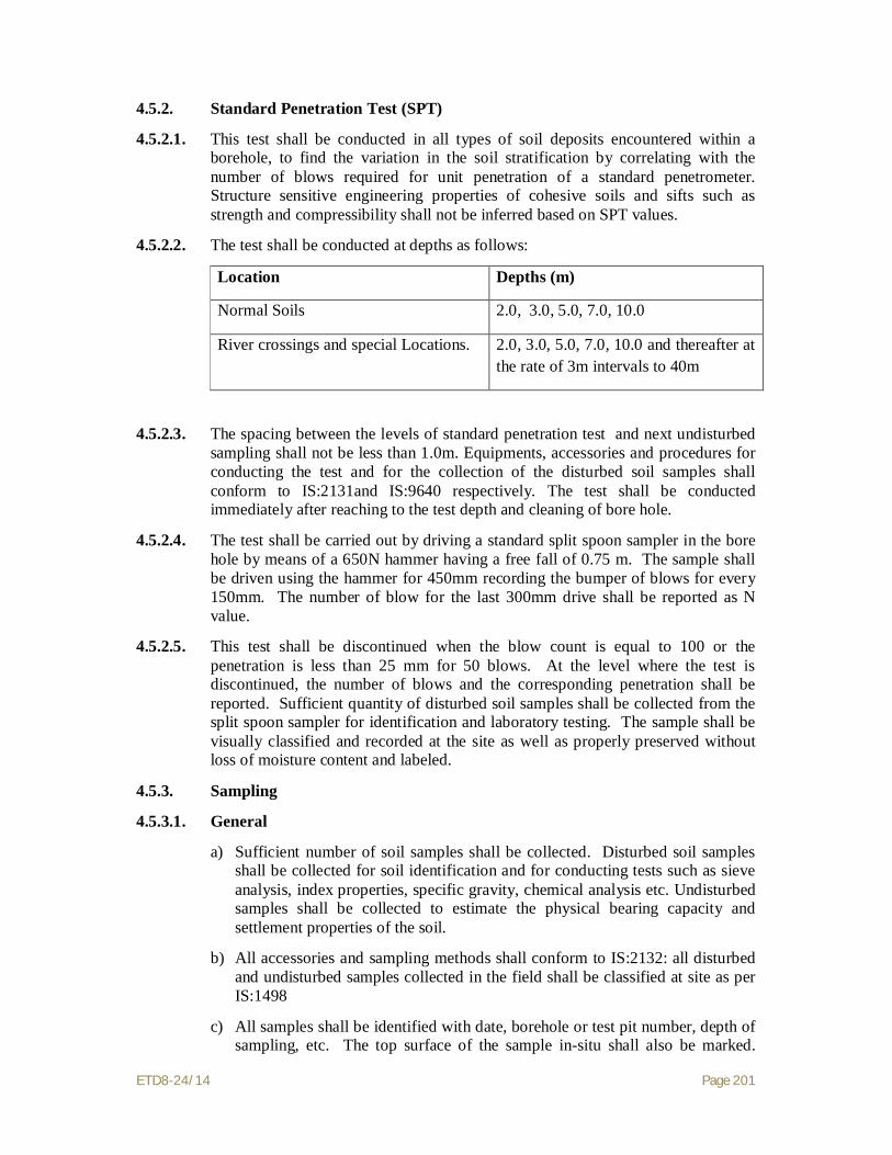
ETD8-24/14 Page 201
4.5.2. Standard Penetration Test (SPT)
4.5.2.1. This test shall be conducted in all types of soil deposits encountered within a borehole, to find the variation in the soil stratification by correlating with the number of blows required for unit penetration of a standard penetrometer. Structure sensitive engineering properties of cohesive soils and sifts such as strength and compressibility shall not be inferred based on SPT values.
4.5.2.2. The test shall be conducted at depths as follows:
Location Depths (m)
Normal Soils 2.0, 3.0, 5.0, 7.0, 10.0
River crossings and special Locations. 2.0, 3.0, 5.0, 7.0, 10.0 and thereafter at the rate of 3m intervals to 40m
4.5.2.3. The spacing between the levels of standard penetration test and next undisturbed sampling shall not be less than 1.0m. Equipments, accessories and procedures for conducting the test and for the collection of the disturbed soil samples shall conform to IS:2131and IS:9640 respectively. The test shall be conducted immediately after reaching to the test depth and cleaning of bore hole.
4.5.2.4. The test shall be carried out by driving a standard split spoon sampler in the bore hole by means of a 650N hammer having a free fall of 0.75 m. The sample shall be driven using the hammer for 450mm recording the bumper of blows for every 150mm. The number of blow for the last 300mm drive shall be reported as N value.
4.5.2.5. This test shall be discontinued when the blow count is equal to 100 or the penetration is less than 25 mm for 50 blows. At the level where the test is discontinued, the number of blows and the corresponding penetration shall be reported. Sufficient quantity of disturbed soil samples shall be collected from the split spoon sampler for identification and laboratory testing. The sample shall be visually classified and recorded at the site as well as properly preserved without loss of moisture content and labeled.
4.5.3. Sampling
4.5.3.1. General
a) Sufficient number of soil samples shall be collected. Disturbed soil samples shall be collected for soil identification and for conducting tests such as sieve analysis, index properties, specific gravity, chemical analysis etc. Undisturbed samples shall be collected to estimate the physical bearing capacity and settlement properties of the soil.
b) All accessories and sampling methods shall conform to IS:2132: all disturbed and undisturbed samples collected in the field shall be classified at site as per IS:1498
c) All samples shall be identified with date, borehole or test pit number, depth of sampling, etc. The top surface of the sample in-situ shall also be marked.

ETD8-24/14 Page 202
Care shall be taken to keep the core and box samples vertical, with the mark directing upwards. The tube samples shall be properly trimmed at one end and suitably capped and sealed with molten paraffin wax. The Contractor shall be responsible for packing, storing in a cool place and transporting all the samples from site to the laboratory within seven days after sampling with probe, protection against loss and damage.
4.5.3.2. Disturbed Samples
a) Disturbed soil samples shall be collected in boreholes at regular intervals. Jar samples weighing approximately 1 kg shall be collected at 0.5m intervals starting from a depth of 0.5m below ground level and at every identifiable change of strata to supplement the boring records. Samples shall be stored immediately in air tight jars which shall be filled to capacity as much as possible.
b) In designated borrow areas, bulk samples, from a depth of about 0.5m below ground level shall be collected to establish the required properties for use as a fill material. Disturbed samples weighing about 25kg (250N) shall be collected at shallow depths and immediately stored in polythene bags as per IS:1892. The bags shall be sealed properly to preserve the natural moisture content of the sample and placed in wooden boxes for transportation.
4.5.3.3. Undisturbed Samples
In each borehole undisturbed samples shall be collected at every change of strata and at depths as follows:
Location Depths (m) Normal Soils 1.0, 4.0, 6.0, 8.0 Special Locations 1.0, 4.0, 6.0, 8.0,11.0 and thereafter at
the rate of 3 m intervals up to 33m
4.5.3.3.1. The spacing between the top levels of undisturbed sampling and standard penetration testing shall not be less than 1.0m. Undisturbed samples shall be of 100mm diameter and 450mm in length. Samples shall be collected in a manner to preserve the structure and moisture content of the soil Accessories and sampling procedures shall conform to IS:1892 and IS:2132
a) Undisturbed sampling in cohesive soil :
Undisturbed samples in soft to stiff cohesive soils shall be obtained using a thin walled sampler. In order to reduce the wall friction, suitable precautions, such as oiling the surfaces shall be taken. The sampling tube shall have a smooth finish on both surfaces and a minimum effective length of 450mm. The area ratio of sampling tubes shall be less than 12.5%. However, in case of very stiff soils area ratio up to 20% shall be permitted.
b) Undisturbed sampling in very loose, saturated, sandy and silty soils and very soft clays :

ETD8-24/14 Page 203
Samples shall be obtained using a piston sampler consisting of a cylinder and piston system. In soft clays and silty clays, with water standing in the casing pipe, piston sampler shall be used to collect undisturbed samples in the presence of expert supervision.
Accurate measurements of the sampling depth, dimensions of sampler, stroke and length of sample recovery shall be recorded. After the sampler is pushed to the required depth, the cylinder and piston system shall be drawn up together, preventing disturbance and changes in moisture content of the sample;
c) Undisturbed sampling in cohesion less soils
Undisturbed samples in cohesion less soils shall be obtained in accordance with IS:8763. Sampler operated by compressed air shall be used to sample cohesion less soils below ground water table.
4.5.4. Ground Water
4.5.4.1. One of the following methods shall be adopted for determining the elevation of ground water table in boreholes as per IS:6935 and the instructions of the Purchaser:
a) In permeable soils, the water level in the borehole shall be allowed to stabilize after depressing it adequately by bailing before recording its level. Stability of sides and bottom of the boreholes shall be ensured at all times.
b) For both permeable and impermeable soils, the following method shall be suitable. The borehole shall be filled with water and then bailed out to various depths. Observations on the rise or fall of water level shall be made at each depth. The level at which neither fall nor rise is observed shall be considered the water table elevation and confirmed by three successive readings of water level taken at two hours interval.
4.5.4.2. If any variation of the ground water level is observed in any specific boreholes, the water level in these boreholes shall be recorded during the course of the filed investigation. Levels in nearby wells, streams, etc., if any, shall also be noted in parallel.
4.5.4.3. Subsoil water samples
a) Subsoil water samples shall be collected for performing chemical analysis. Representative ground water samples shall be collected when first encountered in boreholes and before the addition of water to aid boring or drilling.
b) Chemical analysis of water samples shall include determination of pH value, turbidity, sulphate, carbonate, nitrate and chloride contents, presence of organic matter and suspended solids. Chemical preservatives may be added to the sample for cases as specified in the test methods or in applicable Indian Standards. This shall only be done if analysis cannot be conducted within an hour of collection and shall have the prior written permission and approval of the Purchaser.

ETD8-24/14 Page 204
4.5.5. Dynamic Cone Penetration Test (only at Special locations)
a) With bentonite slurry
Dynamic cone penetration test shall be conducted to predict stratification, density, beating capacity of granular soils, etc. The test shall be conducted to the specified depth or refusal, whichever comes first. Refusal shall be considered when the blow count exceeds 100 for 300 mm penetration. Equipment, accessories test procedures, field observations and reporting of results shall conform to IS: 4968, Part-II. The driving system shall comprise of a 650 N weight hammer having a free fall of 750mm. The cone shall be of 600 and of 65mm diameter provided with vents for continuous flow of bentonite slurry through the cone and rods in order to avoid friction between the rods and soil. On completion of the test the results shall be presented as a continuous record of the number of blows required for every 300mm penetration of the cone into the soil in a suitable chart supplemented by a graphical plot of blow count for 300mm penetration vs. depth. On completion of the test, the results shall be presented on the proforma approved by the Purchaser.
b) Without bentonite slurry
This test shall be conducted with 50mm diameter 600 cone fitted loosely to the driving rod through a cone adopter. The cone shall be driven in to the soil by allowing 650 N weight hammer top fall freely through a height of 750mm each time. The number of blows for every 75mm penetration shall be recorded. The process shall be repeated till the cone is driven to the required depth. The penetration depth shall be limited to 5m in cohesion less soil and 10m in mixed soil with some binding material. The cone driving rods, driving head, hoisting equipment shall conform to IS: 10589. The test report should be prepared as per guidelines of IS: 4968 (Part I).
4.5.6. Vane Shear Test. (required for boreholes where UDS is not possible) (Only at Special Locations)
Field vane shear test shall be performed inside the borehole to determine the shear strength and bearing capacity of cohesive soils, especially of soft and sensitive clays, which are highly susceptible to sampling disturbance. Equipment, accessories, test procedures, field observations shall correspond to IS:4434. Tests may also be conducted by direct penetration from ground surface. If the cuttings at the test depth in the borehole show any presence of gravel, sand shells, decomposed wood, etc., which are likely to influence the test results substantially, the test at that particular depth may be omitted with the permission of the Purchaser. However, the test shall be conducted at a depth where these obstructions cease to occur. On completion of the test, the results shall be reported in an approved proforma as specified in IS:4434, Appendix - A.

ETD8-24/14 Page 205
4.6 Field Investigation for Rock
4.6.1. Rock Drilling
4.6.1.1. If, during the investigations, large hard fragments or natural rock beds are encountered, work shall proceed with core drilling methods. The equipment and procedures for this operation shall conform to IS:1892. The starting depth of drilling in rock shall be certified by the Purchaser. At the end of the investigation, the hole drilled in rock shall be backfilled with grout consisting of 1 part cement and 3 parts sand by weight.
4.6.1.2. Drilling shall be carried out with NX size tungsten carbide (TC) or diamond tipped drill bits, depending on the type of rock and according to IS:6926. Suitable type of drill bit (TC/Diamond) and core catchers shall be used to ensure continuous and good core recovery. Core barrels and core catchers shall be used for breaking off the core and retaining it when the rods are withdrawn. Double tube core barrels shall be used to ensure better core recovery and to retrieve cores from layers of bedrock. Water shall be circulated continuously in the hollow rods and the sludge conveying the rock cuttings to the surface shall be collected. A very high core recovery ratio shall be aimed at in order to obtain a satisfactory undisturbed sample. Attempt shall be made to recover cores of 1.5m in length. Normally TC bit shall be used. Change over to a diamond bit shall require the specific written approval of the Purchaser, and his decision as to whether a TC or a diamond bit is to be used shall be final and binding on Contractor.
4.6.1.3. No drilling run shall exceed 1.5 m in depth. if the core recovery is less than 80% in any run, the length of the subsequent run shall be reduced to 0.75m. During drilling operations observations on return water, rate of penetration etc. shall be made recorded and recorded as per IS:5313.
a) The colour of return water at regular intervals, the depth at which any change of colour of return water is observed, the depth of occurrence and amount of flow of hot water, if encountered, shall be recorded.
b) The depth through which a uniform rate of penetration was maintained, the depth at which marked change in rate of penetration or sudden fail on drill rod occurs, the depth at which any blockage of drill bit causing core loss, if any, shall be recorded.
c) Any heavy vibration or torque noticed during the drilling should be recorded together with the depth of occurrence.
d) Special conditions like the depth at which grouting was done during, drilling, presence of artesian conditions, loss of drilling fluid, observations of gas discharge with return water, etc., shall also be observed and recorded.
e) All the observations and other details shall be recorded as per daily drill and reported in a proforma as given in IS:5313, Appendix A.
4.6.2. Core Sampling
4.6.2.1. Core samples shall be extracted by the application of a continuous pressure at one end of the core with the barrel held horizontally without vibration. Friable cores shall be extracted from the barrel directly into a suitably sized half round plastic

ETD8-24/14 Page 206
channel section. Care shall be taken to extrude the samples in the direction of coring to avoid stress reversal.
4.6.2.2. Immediately after withdrawal from the core barrel, the cores shall be placed in a tray and transferred to boxes specially prepared for this purpose. The boxes shall be made from seasoned timber or any other durably material and shall be indexed on top of the lid according to IS:4078. The cores shall be numbered serially and arranged in the boxes in a sequential order. The description of the core samples shall be recorded as instructed in IS:4464. Where no core is recovered, it shall be recorded as specified in the standard. Continuous record of core recovery and rock quality designation (RD/DD/QD) are to be mentioned in the bore log in accordance with IS:1 1315 (Part-II).
4.7 Laboratory Testing
4.7.1. Essential Requirements
a) Depending on the types of substrata encountered, appropriate laboratory tests shall be conducted on soil and rock samples collected in the field. Laboratory tests shall be scheduled and performed by qualified and experienced personnel who are thoroughly conversant with the work. Tests indicated in the schedule of items shall be performed on soil, water and rock samples as per relevant IS codes. One copy of all laboratory test data records shall be submitted to Purchaser progressively every week. Laboratory tests shall be carried out concurrently with the field investigations as initial laboratory test results could be useful in planning the later stages of field work. A schedule of laboratory tests shall be established by Contractor to the satisfaction of the Purchaser within one week of completion of the first borehole;
b) Laboratory tests shall be conducted using approved apparatus complying with the requirements and specification of Indian Standards or other approved standards for this type of work. It shall be checked that the apparatus are in good working condition before starting the laboratory tests. Calibration of all the instruments and their accessories shall be done carefully and precisely at an approved laboratory.
c) All samples, whether undisturbed or disturbed shall be extracted, prepared and examined by competent personnel properly trained and experienced in soil sampling. examination, testing and in using the apparatus in conformance with the specified standards;
d) Undisturbed soil samples retained in liners or seamless tube samplers shall be removed, without causing any disturbance to the samples, using suitably designed extruders just prior to actual testing. If the extruder is horizontal, proper support shall be provided to prevent the sample from breaking. For screw tube extruders, the pushing head shall be free from the screw shaft so that no torque is applied to the soil sample in contact with the pushing head. For soft clay samples, the sample tube shall be cut by means of a high speed hacksaw to proper test length and placed over the mould before pushing the sample into it with a suitable piston;
e) While extracting a sample from a liner or tube, care shall be taken to assure that its direction of movement is the same as that during sampling to avoid stress reversal;

ETD8-24/14 Page 207
4.7.2. Tests
4.7.2.1. Tests as indicated in these specifications and as may be requested by the Purchaser, shall be conducted. These tests shall include but may not be limited to the following :
a) Tests of undisturbed and disturbed samples
Visual and engineering classification;
Sieve analysis and hydrometric analysis;
Liquid, plastic and shrinkage limits;
Specific gravity;
Chemical analysis
Swell pressure and free swell index determination
Proctor compaction test.
b) Tests of undisturbed samples:
Bulk density and moisture content;
Relative density(for sand),
Unconfined compression test;
Box shear test (for sand);
Triaxial shear tests (depending on the type of soil and field conditions on undisturbed or remoulded samples):
i. Unconsolidated undrained;
ii. Consolidated drained test;
Consolidation.
c) Tests on rock samples
Visual classification;
Moisture content , porosity and density;
Specific gravity;
Hardness
Stake durability
Unconfined compression test (both saturated and at in-situ water content);
Point load strength index;
Deformability test(both saturated and dry samples).

ETD8-24/14 Page 208
d) Chemical analysis of sub soil water.
4.7.3. Salient Test Requirement
a) Triaxial shear tests shall be conducted on undisturbed soil samples, saturated by the application of back pressure. Only if the water table is at sufficient depth so that chances of its rising to the base of the footing are small or nil, the triaxial tests shall be performed on specimens at natural moisture content. Each test shall be carried out on a set of three test specimens from one sample at cell pressures equal to 100, 200 and 300 KPa respectively or as required depending on the soil conditions:
b) Direct shear test shall be conducted on undisturbed soil samples. The three normal vertical stresses for each test shall be 100, 200 and 300 KPa or as required for the soil conditions;
c) Consolidation test shall have loading stages of 10, 25, 50, 75, 100, 200, 400 and 800 KPa. Rebound curve shaft be recorded for all samples by unloading the specimen at its in-situ stress. Additional rebound curves shall also be recorded wherever desired by the Purchaser;
d) Chemical analysis of subsoil shaft include determination of PH value, carbonate, sulphate (both SO3 and SO4). chloride and nitrate contents, organic matter, salinity and any other chemicals which may be harmful to the foundation material. Their contents in the soil shall be indicated as percentage (%);
e) Chemical analysis of subsoil water samples shall include the determination of properties such as colour, odour, turbidity, PH value and specific conductivity, the last two chlorides, nitrates, organic matter and any other chemical harmful to the foundation material. The chemical contents shall be indicated as parts per million (PPM) based on weight.
4.8 Geotechnical Investigation Report
4.8.1. General
Contractor shall submit a formal report containing geological information of the region, procedures adopted for geotechnical investigation, field observations, summarised test data, conclusions and recommendations. The report shall also include detailed bore logs, subsoil sections, field test results, laboratory observations and test results both in tabular as well as graphical form, practical and theoretical considerations for the interpretation of test results, supporting calculations for the conclusions drawn, etc. Initially, Contractor shall submit three copies of the report in draft form for Purchaser’s review;
a) Contractor’s Geotechnical engineer shall visit Purchaser’s Corporate Office for a detailed review based on Purchaser’s comments in order to discuss the nature of modifications, if any, to be done in the draft report. Contractor shall incorporate in the report the agreed modifications and resubmit the revised draft report for approval. Ten copies of the detailed final approved report shall be submitted to Purchaser together with one set of reproducible of the graphs, tables etc.
ETD8-24/14 Page 209
b) The detailed final report based on field observations, in-situ and laboratory tests shall encompass theoretical as well as practical considerations for foundations for different types of structures.
4.8.2. Data to be furnished
4.8.2.1. The report shall also include the following
a) A plot plant/location plan showing the locations and reduced levels of all field test e.g. boreholes, trial pits, static cone penetration tests, dynamic cone penetration tests, etc., property drawn to scale and dimensioned with reference to the established grid lines;
b) A true cross section of all individual boreholes and test pits with reduced levels and co-ordinates showing the classification and thickness of individual stratum, position of ground water table, various in-situ tests conducted, samples collected at different depths and the rock stratum, if encountered;
c) Geological information of the area including geomorphology, geological structure, lithology, stratigraphy and tectonics, core recovery and rock quality designation (RD/DD/QD), etc.,
d) Observations and data regarding change of course of rivers, velocity, scour depths, slit factor, etc., and history of flood details for mid stream and river bank locations;
e) Past observations and historical data, if available, for the area or for other areas with similar soil profile, or with similar structures in the surrounding areas;
f) Plot of Standard Penetration Test (uncorrected and corrected N values) with depth for each test site;
g) Results of all laboratory test summarised according to Table 4.0 (i) for each sample as well as (ii) for each layer, along with all the relevant charts, tables, graphs, figures, supporting calculations, conclusions and photographs of representative rock cores,
h) For all triaxial shear tests, stress vs. strain diagrams as well as Mohr’s circle envelopes shall be furnished. If back pressure is applied for saturation, the magnitude of the same shall be indicated. The value of modulus of elasticity (E) shall be furnished for all tests along with relevant calculations;
i) For all consolidation tests, the following curves shall be furnished
i. e vs. log p;
ii. e vs. p;
iii. Compression vs log t or vst
depending upon the shape of the plot, for proper determination of coefficient of consolidation.
The point showing the initial condition (e0, p0) of the soil shall be marked on the curves;

ETD8-24/14 Page 210
j) The procedure adopted for calculating the compression index from the field curve and settlement of soil strata shall be clearly specified. The time required for 50% and 90% primary consolidation along with secondary settlements, if significant, shall also be calculated.
SUMMARY OF RESULTS OF LABORATORY TESTS ON SOIL
AND WATER SAMPLES
1. Bore hole test pit. no
2. Depth (m)
3. Type of sample
4. Density(kg/m3) a) Bulk b) Dry. c) Submerged
5. Water content (%)
6. Particle Size (%) a) Gravel b) Sand c) Silt d) Clay
7. Consistency properties a) LL b) PL c) PI d) LI
8. Soil a) Classification -IS b) Description c) Specific gravity
9. Strength Test a) Type b) C (Cohesion) c) Ø (angle of internal friction) d) Angle of repose
10. Consolidation Test a) e0 b) Pc c) Cc d) DP e) Mv f) Cv
11. Shrinkage limit(%)
12. Swell Test

ETD8-24/14 Page 211
a) S.Pr b) FS
13. Relative Density (%)
14. Remarks
Notations:
I. For type of Sample:
DB - Disturbed bulk soil sample.
DP - Disturbed SPT soil sample
DS - Disturbed samples from cutting edge of undisturbed soil sample.
RM - Remoulded soil sample
UB - Undisturbed block soil sample
US - Undisturbed soil sample by sampler
W - Water sample
II. For Strength Test :
SCPT - Static Cone Penetration Test
UCC - Unconfined Compression Test
VST - Vane Shear Test
Tuu - Unconsolidated Undrained Triaxial Test
Note: Replace T by D for Direct Shear Test
Tod - Consolidation Drained Triaxial Test
III. For Others :
LL - Liquid Limit (%)
PL - Plastic Limit
PI - Plasticity Index
LI - Liquidity Index
C - Cohesion (kPa)
Ø - Angle of Internal Friction (degrees)
S-Pr. - Swelling Pressure (kPa)
e0 - Initial Void Ratio
Pc - Reconsolidation Pressure (kPa)

ETD8-24/14 Page 212
Cc - Compression Index
DP - Change in Pressure (kPa)
mv - Coefficient of Volume Compressibility (m2/KN)
Cv - Coefficient of Consolidation (m2/hr)
IV. For Chemical Test
As per Specifications - Clause 4.8.4
4.8.3. Recommendations
4.8.3.1. Recommendations shall be provided for each tower location duly considering soil type and tower spotting data. The recommendations shall provide all design parameters and considerations required for proper selection, dimensioning and future performance of tower foundations and the following
a) The subsurface material must provide safe bearing capacity and uplift resistance by incorporating appropriate safety factors thereby avoiding rupture under ultimate loads;
b) Movement of the foundation, including short and long term components under transient and permanent loading, shall be strictly controlled with regard to settlement, uplift, lateral translation and rotation:
c) Co-efficient of permeability of various sub soil and rock strata based on in-situ permeability tests.
Core resistance, frictional resistance total resistance, relation between core resistance, Standard Penetration Test N value, and settlement analysis for different sizes of foundation as specified in para 4.1.8.3 (I) based on static cone penetration test.
d) For shallow foundation the following shall be indicated with comprehensive supporting calculations:
i. Net Safe allowable bearing pressure for isolated square footing of sizes 4.0, 5.0, 6.0 & 7. m at three different founding depths of 1,2 and 3 & 3.5m below ground level considering both shear failure and settlement criteria giving reasons for type of shear failure adopted in the calculation.
ii. Net safe allowable bearing pressure for raft foundations of widths greater than 5m at 2.0, 3.0 and 4.0m below ground level considering both shear failure and settlement criteria.
iii. Rate and magnitude of settlement expected of the structure.
iv. Net safe bearing capacity for foundation sizes mentioned in para(i) above, modulus of sub grade reaction, modules of elasticity from plate load test results along with time settlement curves and load settlement curve in both natural and log graph, variation of Modulus of sub grade reaction with size, shape and depth of foundation.
ETD8-24/14 Page 213
e) The stable slopes for shallow and deep excavations, active and passive earth pressure at rest and angle of repose for sandy soils shall be furnished. The loading of the foundations shall not compromise the stability of the surrounding subsurface materials and the stability of the foundation shall be ensured against sliding or overturning:-
f) Depending on the subsurface material, water table level and tower type, either reinforced concrete isolated pad and chimney, cast-in-situ bored pile of special foundations shall be installed at a given location.
g) Net Safe allowable bearing pressure and uplift resistance shall be provided for the various sizes of isolated square footings founded at various depths below ground level considering both shear failure and movement criteria; rate and magnitude of movement expected of the structure (settlement, uplift, rotation) shall also be given.
h) In cases where normal open cast/pile foundations appear to be impractical, special pile foundations shall be given due consideration along with the following:
i. Type of pile foundation and reasons for recommending the same duly considering the soil characteristics.
ii. Suitable founding strata for the pile:
iii. Estimated length of pile for 500, 750 and 1000 KN and 4500 KN capacities; end bearing and frictional resistance shall be indicated separately:
iv. Magnitude of negative skin friction or uplift forces due to soil swelling.
i) Where the subsoil water and soil properties are found to be chemically aggressive. Contractor shall take suitable precautions during construction including any protective coating to be applied on the foundations; susceptibility of soil to termite action and remedial measures for the same shall be dealt with;
j) Suitability of locally available soils at sit ee for filling, backfilling and adequate compaction shall be investigated.
k) If expansive soil such as black cotton soil is encountered recommendation of removal or retainment of the same shall be given in the latter case, detailed specifications of special requirements shall also be given;
l) Susceptibility of subsoil strata to liquefaction in the event of earthquake and remedial measures, if required, shall be considered.
m) Any other information of special significance such as dewatering schemes, etc. which may have a bearing on the design and construction shall be provided.
n) Recommendations for additional soil investigations, beyond the scope of the present work, shall be given if Contractor considers such investigations necessary.

ETD8-24/14 Page 214
4.8.4. Hydrogeological Conditions
4.8.4.1. The maximum elevation of ground water table, amplitudes of its fluctuations and data on water aggressivity with regard to foundation structure materials shall be reported. While preparing ground water characteristics the following parameters should be specified for each aquifer:
a) bicarbonate alkalinity mg-eq/(deg),
b) pH value
c) content of aggressive carbon dioxide, mg/l;
d) content of magnesia salts, mg/l, recalculated in terms of ions Mg+2;
e) content of ammonia salts, mg/l, recalculated in terms of ions NH4+
f) content of caustic alkalis, mg/l, recalculated in terms of ions Na+ and K+
g) contents of chlorides,mg/l recalculated in terms of ions Cl-
h) contents of sulphates, mg/l, recalculated in terms of ions SO4-2
i) aggregate content of chlorides, sulphates, nitrates, carbonates and other salts. mg/l.
4.9 Rates and Measurements
4.9.1. Rates
The contractor’s quoted rates shall be inclusive of making observations, establishing the ground level and co-ordinates at the location of each borehole, test pit etc. No extra payments shall be made for conducting Standard Penetration Test, collecting, packing, transporting of all samples and cores, recording and submittal of results on approved formats.
4.10 Specific Requirements for Geotechnical Investigation at River Crossings.
4.10.1. The entire soil investigation work at river crossing locations (if required) shall be carried out in accordance with the relevant parts of the specifications for geotechnical investigation modified to the extent given below.
4.10.2. Requirements
4.10.2.1. Boreholes shall be executed to specified depth of 40m (refer clause 4.5.1.1 b). If refusal strata is reached (i.e. SPT-N value is greater than 100 continuously for 5m depth) with characteristics of rock the borehole may be terminated at shallower depth i.e. at 5m in refusal strata, with prior approval of the Purchaser.
4.10.2.2. Laboratory testing shall be conducted on all soil samples to determine grain size distribution, liquid limit and plastic limit of the different soil strata encountered.
4.10.2.3. Geotechnical Report must furnish the following:
a) Geotechnical investigation scheme;
b) Bore-logs indicating soil stratification, with IS classification, sampling details and SPI ‘N’ values.

ETD8-24/14 Page 215
c) Soil cross-sections along various boreholes in two orthogonal directions indicating soil stratification based on field and laboratory tests;
d) Grain size distribution curves.
e) IS classification of soils.
f) Shear tests (UU) to be done on saturated soil samples;
g) Bearing capacity of soil at different levels;
h) Highest flood level (H.F.L.);
i) Maximum discharge, velocity etc. (from authenticated source such as CWC or appropriate State authorities)
j) Recommendations regarding type of foundation to be adopted at the location.
4.10.3. A check list for reporting results of river crossing locational details, detailed soil investigation and river values for river crossing locations is enclosed at Annexure-C.
4.11 Special Terms and conditions for Geotechnical Investigation in the River bed
4.11.1. Contractor is required to mobilise a suitable arrangement (floating pontoon, plant, equipment etc,) to carry out geotechnical investigation work in creek/river locations identified by the Purchaser.
4.11.2. In the event of storm or stoppage of work, etc., Contractor shall not be paid extra for mobilization / remobilisation of floating pontoon, plant, equipment, etc.
4.11.3. Contractor shall fully satisfy himself about the conditions of creek/river (depth of water, wave currents, wind conditions, etc.) prevailing in the area of proposed investigation and plan the necessary tools and plant to be deployed before quoting. Any claim resulting from lack of data collection in this respect shall not be entertained.
4.11.4. Contractor shall make his own arrangements for locating the coordinates and position of boreholes in creek/river with respect to two grid-lines indicated by Purchaser.
4.11.5. Boring in creek or river shall be payable only below the bed level and no payment shall be made for lowering the casing in water.
4.11.6. Contractor shall arrange for necessary transportation on water (e.g. motor boat) to facilitate the supervision of work by officials of Purchaser at its own cost.
4.11.7. Full details of the construction plant, proposed working method for boring and sampling in water shall be submitted along with the Tender.
4.11.8. The unit rate quoted for underwater boring shall include complete work required as per specification and no separate payment shall be made on any account.
5. STATUTORY REGULATIONS AND STANDARDS
5.1 Contractor is required to follow statutory regulations stipulated in Electricity Act 2003, Indian Electricity Rules and other local rules & regulations.

ETD8-24/14 Page 216
5.2 The codes and standards referred to in these specifications shall govern. In case of a conflict between such codes/standards and these specifications, the provisions of the specifications shall prevail. Such codes, standards referred to shall mean latest revisions, amendments, changes adopted and published by relevant agencies.
5.3 Other Internationally acceptable standards which ensure equivalent or better performance than those specified shall also be acceptable.
6. FIELD QUALITY PLAN
All field activity shall be carried out in accordance with Standard Field Quality plan submitted by the contractor and approved by the purchaser.
ETD8-24/14 Page 217
SECTION-IV
TOWER, FOUNDATION, ERECTION,
STRINGING AND COMMISSIONING OF LINE
ETD8-24/14 Page 218
TECHNICAL SPECIFICATION (SECTION-IV)
TOWER, FOUNDATION, ERECTION, STRINGING
AND COMMISSIONING OF LINE 1.0 Transmission Tower The general description of towers applicable for the package and technical
particulars thereof are indicated in Section–I of this Specification. 1.1 Design and Drawings 1.1.1 The relevant drawings for all the towers and their extensions shall be furnished to
the Contractor by the purchaser which shall include structural drawings/erection drawings and / or shop fabrication drawings, Bill of Materials for all the towers and their extensions as well as construction drawings for foundations.
1.1.2 The tower members can be directly fabricated from the structural/erection drawings wherever the required fabrication details are provided on the same or shop fabrication drawings. However, if the contractor is required to prepare shop fabrication drawings, of their own, in addition to the structural / erection drawings with required fabrication details, they may prepare the same without any additional financial implication to purchaser. Before taking up mass fabrication, the Contractor shall arrange for one number proto-assembly for each type of towers and extensions which shall be inspected by purchaser. After assembly inspection the Contractor shall incorporate revisions in the drawings. The revised drawing shall be submitted in 3 (three) copies for final approval by the purchaser.
1.1.3 All the drawings shall have a proper name plate clearly displaying the name of purchaser on right hand bottom corner. The exact format of the nameplate shall be handed over to the successful bidder for incorporation of the same on all the drawings. Also all the drawings shall carry the following statement and shall be displayed conspicuously on the drawing:
WARNING: THIS IS PROPRIETORY ITEM AND DESIGN RIGHT IS STRICTLY RESERVED WITH PURCHASER. UNDER NO CIRCUMSTANCES THIS DRAWING SHALL BE USED BY ANYBODY WITHOUT PRIOR PERMISSION FROM THE PURCHASER IN WRITING.
1.1.4 While submitting the structural drawings, bill of materials, shop drawings and any other drawings pertaining to the subject transmission line, the Contractor shall clearly indicate on each drawing purchaser Specification No., Name of the specific Transmission line and project, letter reference no. and date on which the submission are made. The same practice is also to be followed while submitting distribution copies.
1.1.5 The tower accessories drawings like number plate, phase plate, Danger plate, circuit plate, step bolt, earthing etc have been standardized and are enclosed with this specification of the specification. The contractor is required to submit the distribution copies of above drawing after endorsing the name of the project. However, drawing of anti-climbing device, D-shackle etc. shall be prepared by the Contractor and shall be submitted to the Purchaser, in three (3) copies for approval. This drawing shall be prepared in A4 size only.
1.1.6 The drawings prepared and submitted by the Contractor shall be approved / commented by the purchaser as the case may be within fifteen (15) days of receipt of drawings in his office. If the designs/drawings are commented by the

ETD8-24/14 Page 219
purchaser, the Contractor shall submit revised design/drawings duly incorporating all comments within fifteen (15) days of date of issue of comments. The Contractor shall submit 15 copies of all approved structural drawings and BOM for tower extensions as well as for tower accessories for further distribution by the purchaser.
The mass fabrication shall be taken up from the approved shop drawings. The overall responsibility of fabricating tower members correctly lies with the Contractor only and the Contractor shall ensure that all the tower members can be assembled / fitted while erecting without any undue strain on them.
1.1.7 Other than the items indicated above some other drawings and documents, such as BOM, Shop drawings, structural drawings for river crossing tower etc. which are required for the project shall also be developed by the Contractor. However, no extra cost on this account shall be payable to the Contractor.
1.2 Materials 1.2.1 Tower Steel Sections IS Steel Sections of tested quality of conformity with IS:2062 :2006 grade E250
(Designated Yield Strength. 250 MPa) and/ or grade E350 (Designated Yield Strength 350 MPa) are to be used in towers, extensions, stubs and stub setting templates. The Contractor can use other equivalent grade of structural steel angle sections and plates conforming to latest International Standards. However, use of steel grade having designated yield strength more than that of EN 10025 grade S355 JR/JO (designated yield strength 355 MPa) is not permitted, unless otherwise indicated in this specification.
Steel plates below 6mm size exclusively used for packing plates/packing washers produced as per IS 1079 -1994 (Grade -0) are also acceptable. However, if below 6mm size plate are used as load bearing plates viz gusset plates , joint splices etc. the same shall conform to IS : 2062 / or equivalent standard meeting mechanical strength/metallurgical properties corresponding to grade E250 or grade E350 (designated yield strength not more than 355MPa), depending upon the type of grade incorporated into design. Flats of equivalent grade meeting mechanical strength/ metallurgical properties may also be used in place of plates for packing plates/ packing washers. The chequered plates shall conform to IS : 3502. SAILMA 350HI grade plate can also be accepted in place of HT plates (EN 10025 grade S355 JR/JO / IS 2062:2006 – grade 350, as applicable) provided SAILMA 350HI grade plate meet all the mechanical properties of plate as per EN 10025 grade S355 JR/JO (designated yield strength 355 MPa) / IS 2062:2006 – grade 350.
For designing of towers, preferably rationalised steel sections has been used. During execution of the project, if any particular section is not available, the same shall be substituted by higher section. Any cost on account of the same shall be borne by the Contractor. However, design approval for such substitution shall be obtained from the Owner before any substitution and records of such substitutions shall be maintained by the Contractor.
1.2.2 Fasteners: Bolts, Nuts and Washers including Anti-theft Bolts & Nuts 1.2.2.1 All tower members shall be joined together with Bolts and nuts. The redundant
members of first two (2) panels from ground level shall be connected with Anti-theft bolts and nuts along with spring washers whereas the balance joints shall be connected with hexagonal bolts and nuts. All hexagonal bolts and nuts shall conform to IS-12427. They shall have hexagonal head and nuts, the heads being forged out of the solid, truly concentric, and square with the shank, which must be perfectly straight.
ETD8-24/14 Page 220
Anti-theft bolts and nuts shall have round tapered heads with hexagonal shear nuts. They shall confirm to IS : 12427 and IS : 1367 for property class 5.6/5 except for dimensions which shall be as per enclosed drawing no. TDTL/400kV/ATB. All bolts and nuts shall be galvanised as per IS : 1367 (Part-13)/IS : 2629.
1.2.2.2 The bolt shall be of 16/24 mm diameter and of property class 5.6 as specified in IS : 1367 (Part-III) and matching nut of property class 5.0 as specified in IS : 1367 (Part-VI).
1.2.2.3 Bolts up to M16 and having length up to 10 times the diameter of the bolt should be manufactured by cold forging and thread rolling process to obtain good and reliable mechanical properties and effective dimensional control. The shear strength of bolts for 5.6 grade should be 310 MPa minimum as per IS : 12427. Bolts should be provided with washer face in accordance with IS : 1363 (Part-I) to ensure proper bearing.
1.2.2.4 Nuts for hexagonal bolts should be double chamfered as per the requirement of IS : 1363 Part-III. It should be ensured by the manufacturer that nuts should not be over tapped beyond 0.4mm oversize on effective diameter for size up to M 16. Nuts for anti-theft bolts should be round tapered with hexagonal shear nuts. The hexagonal portion of shear nuts shall break away at specified torque recommended by the supplier to ensure proper tightening of members and the fasteners shall not be opened subsequently with tools. The tightening torque and shearing of anti-theft nuts shall be verified during proto-assembly.
1.2.2.5 Fully threaded bolts shall not be used. The length of bolts shall be such that the threaded portion will not extend into the place of contact of the members.
1.2.2.6 All bolts shall be threaded to take the full depth of the nuts and threaded for enough to permit firm gripping of the members, but not further. It shall be ensured that the threaded portion of each bolt protrudes not less than 3mm and not more than 8mm when fully tightened. All nuts shall fit tight to the point where the shank of the bolt connects to the head.
1.2.2.7 Flat and tapered washers shall be provided wherever necessary. Spring washers shall be provided for insertion under all nuts. These washers shall be steel electro galvanised, positive lock type and 3.5 mm in thickness for 16 mm dia bolt and 4.5 mm for 24 mm bolt.
1.2.2.8 To avoid bending stress in bolts or to reduce it to minimum, no bolt shall connect aggregate thickness of members more than three (3) times its diameter.
1.2.2.9 The bolt positions in assembled towers shall be as per structural drawing. 1.2.2.10 Bolts at the joints shall be so staggered that nuts shall be tightened with spanners
without fouling. 1.2.2.11 To ensure effective in-process Quality control it is desirable that the manufacturer
should have in house testing facility for all tests like weight of zinc coating, shear strength and other tests etc. The manufacturer should also have proper Quality Assurance System which should be in line with the requirement of this specification and IS : 14000 series Quality System Standard.
1.3 Tower Accessories Arrangement shall be provided for fixing of all tower accessories to the tower, at
a height between 2.5 meters and 3.5 meters above the ground level. 1.3.1 Step Bolts & Ladders Each tower shall be provided with step bolts as per drawing enclosed in the
section of drawing. The contractor shall submit distribution copies of the same endorsing the package details (i.e. line name, LOI No. etc). The step bolts conforming to IS: 10238 of not less than 16mm diameter and 175mm long,

ETD8-24/14 Page 221
spaced not more than 450mm apart and extending from 2.5 meters above the ground level to the top of the tower. However, the head diameter shall be 50mm as indicated in the enclosed drawing. For Double circuit tower the step bolt shall be fixed on two diagonally opposite legs up to top of the towers. Each step bolt shall be provided with two nuts on one end to fasten the bolt securely to the tower and button head at the other end to prevent the feet from slipping away. The step bolts shall be capable of withstanding a vertical load not less than 1.5 KN. For special towers, where the height of the super structure exceeds 50 meters, ladders along with protection rings, as per purchaser approved design shall be provided in continuation of the step bolts on one face of the tower from 30 meters above ground level to the top of the special structure. From 2.5 m to 30m height of super structure step bolts shall be provided. Suitable platform using 6 mm thick perforated chequered plates along with suitable railing for access from step bolts to the ladder and from the ladder to each cross-arm tip and the ground wire support shall also to be provided. The platform shall be fixed on tower by using counter-sunk bolts.
1.3.2 Insulator Strings and Earth wire Clamps Attachments a) For the attachment of suspension Insulator string, a suitable dimensioned
swinging hanger on the tower shall be provided so as to obtain specified clearances under respective swinging condition of the strings. The hanger, extensions links, D-shackles etc. as required and considered in the design of the tower shall have minimum ultimate tensile strength of 120 KN for single suspension string and 240 KN for double suspension string for 400 KV suspension towers. The design and supply of hanger, D-shackles, strain plate, extension link etc. are also in the scope of Contractor.
b) At tension towers, strain plates of suitable dimensions under each cross-arm tip, shall be provided for taking the hooks or D-shackles of the tension insulator strings. Full details of the attachments shall be provided to the contractor. To achieve requisite clearances, if the design calls for providing extra D-shackles, link plate etc. before connecting the insulator string the same shall be supplied by the Contractor.
1.3.3 Earth wire Clamps Attachments a) Suspension Clamp Wherever required, the Contractor shall supply U – bolts, D – Shackles etc. for
attachment of Suspension clamp to the tower and take Purchaser’s approval for details of the attachments before the mass fabrication.
b) Tension Clamps Earth wire peaks of tension towers shall be provided with suitable plates to
accommodate the shackle of tension clamps. The contractor shall also supply the U-bolts wherever required and take Purchaser’s approval for details of the attachments before the mass fabrication.
1.3.4 Anti climbing Device Barbed wire type anti climbing device, as per enclosed drawing shall be provided
and installed by the Contractor for all towers. The barbed wire shall conform to IS-278 (size designation A1). The barbed wires shall be given chromating dip as per procedure laid down in IS : 1340.
1.3.5 Danger, Number, Circuit and Phase plate Danger Plates, Phase Plates and Number plates shall be provided and installed by
the Contractor. Further Circuit plates also shall be provided and installed by the contractor for the Double circuit towers. These Danger/Number/Phase/ circuit Plate shall be as per the drawing enclosed in the section of drawing. The

ETD8-24/14 Page 222
contractor shall submit distribution copies of the same endorsing the package details (i.e. line name, LOI No. etc) and installed by the Contractor. a) Each tower shall be fitted with a danger plate, number plate and a set of
phase plates for single circuit tower and two sets of phase plates for double circuit tower. The transposition towers should have provision of fixing phase plates on both the transverse faces. Circuit plates shall be provided on all the Double Circuit and Multi Circuit towers.
b) The letters, figures and the conventional skull and bones of danger plates shall conform to IS-2551 and shall be in a signal red on the front of the plate.
c) The corners of the danger, number and circuit plates shall be rounded off to remove sharp edges.
d) The letters of number and circuit plates shall be red enamelled with white enamelled background.
1.3.6 Aviation Requirements 1.3.6.1 Aviation requirements conforming to IS: 5613 shall be in the scope of Contractor. 1.3.6.2 Night Markers (Obstruction lights) 1.3.6.2.1 The scope of night markers covers the design, manufacture, testing at
manufacturers works, if any, supply, delivery, erection, testing and commissioning of medium intensity, low intensity, lights along with storage battery & solar panel, control panel, cables, clamps other accessories etc. as per the provision of IS-5613 (Part-II/ section-I), 1989, amendment no. 1, July, 94 regarding night & day visual aids for denoting transmission line structures as per the requirement of directorate of flight safety.
1.3.6.2.2 The detail of each component of medium intensity, low intensity lights & associated accessories to be provided on the towers shall be as per the technical specifications given in the preceding clauses and IS/ICAO, International Standards recommended practices. The light on top of the structure should flash at the rate of 20 sequences per min.
1.3.6.2.3 One set of Aviation Lights shall consist of one medium intensity light & two/four (as applicable) low intensity lights along with all accessories such as solar panel, control panel, batteries, cables etc.
1.3.6.2.4 Medium Intensity Light Medium Intensity light shall be provided on the top of each tower. The medium
light should have night time intensity as per ICAO requirements in international Standards Recommended Practices. The light on top of the structure should flash at the rate of 20 sequences per minute. The effective intensity during night time for the medium flashing light shall be 1600 CD. The light shall conform to ICAO requirements/BS 3224a and shall have weather protection conforming to IP-55..
The above lights conforming to ICAO specifications flashing red lights shall be DC operated through a suitably sized battery bank at the operating voltage 12V/24V DC. The burning life of the lamps shall be maximum possible in view of the maintenance hazard of H.T. live but in no case it should be less than 15,000 burning hours. In case of failure of the lamp before 15,000 burning hours, the same shall have to be replaced by the Contractor free of cost. The light shall be equipped with radio suppression facility conforming to BS800 in order to avoid any interference with signals of PLCC etc.
ETD8-24/14 Page 223
1.3.6.2.5 Low Intensity Lights Two/four (as applicable) nos. of low intensity lights are required to be put on each of the towers. Placement drawing for the same shall be submitted by the bidder Contractor.
The light shall be stationary lamp with minimum effective intensity of 10 CD. of red light. The lamps shall conform to the ICAO requirement/relevant BS and shall have weather protection of minimum IP-55 class.
Two/four nos. of L.I. lamp required for each tower shall be operated through a suitable size common battery bank solar panel as per the requirement of operating voltage and load current of the type of lamps being offered.
The burning life of the lamps shall be maximum possible in view of the maintenance hazard of H.T live line, but in no case it should be less than 15,000 burning hours. In case of failure of the lamp before 15,000 hrs. the same shall have to be replaced by the Contractor free of cost even if the pendency of contract expires. Performance certificate of the lamps to be offered shall be furnished by the Contractor.
The low intensity lamp shall not generate any R.F. which can interfere with the PLCC signals.
1.3.6.2.6 Storage Battery Storage Battery required for the above purpose shall be sealed maintenance free,
valve regulate lead acid and suitable for mounting on the top of the transmission line towers. Contractors shall offer the most optimum capacity of the Battery Bank at 120 hour discharge rate (considering 80 % percentage usage) matching with the load requirement of the type of lamps being offered including any power loss in the associated cables. The battery sizing shall conform to JISC 8707/relevant Indian Standard or any other internationally recognized standard. The battery shall be hermetically sealed explosion proof and self-resealing type and free from orientation constraints. The working temperature ranges shall be minimum 0 degree centigrade and maximum 50 degree centigrade. Performance certificate of the offered batteries shall be submitted by the Contractor.
1.3.6.2.7 Battery Box The battery box suitable for mounting on 400 kV power transmission tower shall
be robust construction suitable to accommodate desired number of SOLAR BATTERIES WITH proper clearance between the batteries. The sides and the top of the battery box shall be made from MS sheets not less than 14 SWG thicknesses duly mounted on MS angle frame. The bottom of the battery box shall have suitably designed MS structure to freely hold the total weight of the batteries. The batteries should be placed on insulated base with proper drainage holes. Lifting lugs shall be provided. Dust and vermin proof lockable doors shall be provided for safety and easy access to the batteries for the maintenance. The battery box should incorporate the design for proper ventilation system in order to prevent a gas concentration inside the box. The ventilation opening shall be protected against rain/splash water and dust. The inside of the battery box shall be lined with insulating polyurethane plating and the exterior painted with weather proof polyurethane paint. The cable entry into the battery box shall be through suitable cable glands.
1.3.6.2.8 Solar Modules Solar module required for the system shall be suitable for mounting on the
transmission line towers and shall be designed for high performance, maximum reliability and minimum maintenance and shall be installed below bottom cross arms levels. The solar modules shall be IP 55 grade protection class. These

ETD8-24/14 Page 224
should be highly resistant to water, abrasion, nail, impact and other environmental factors.
These should be placed on the tower at a most optimum angle so as to harness the maximum solar energy and facilitate self cleaning and shall conform to relevant Indian/International Standards.
Module mounting frames shall be weather proof suitable for mounting on tall towers. Details of mounting frames shall be furnished by the Contractor.
Junction box shall be provided with weather proof hinged lid with provision for cable glands entry and protections grade of class IP-55.
The Contractor shall submit the basis of selecting the numbers of solar modules. The provision for design, supply & erection of mounting arrangements for
photovoltaic modules on the transmission towers in a suitable manner to harness maximum solar energy shall be in the scope of the Contractor.
Provision for design, supply & erection of resting platform for the erection of battery bank in a closed enclosure with safety arrangement on the transmission towers shall also be in the scope of the Contractor the design and load consideration for safety of towers due to additional plate form shall be kept in view while designing, selecting the above.
1.3.6.2.9 Control Panels Control panels shall consist of solar charge controller, flasher unit, sensor,
isolator, MCB, Voltmeter, Ammeter and other control gears. Panel enclosure shall be fabricated out of 14 SWG CRCA sheet and thoroughly treated and painted. Suitable neoprene rubber gasket and pad locking device shall be provided and the protection class shall be of IP-55 class.
The Solar charge controller shall be most efficient and preferably fully solid state. It shall be provided with protection to load against increase in temperature. Surge, automatic low voltage and automatic disconnection and reconnection during high inrush current and normalcy respectively.
The flash regulator shall be provided for regulating light flashing. The same shall be completely solid state and provided with flash rate set points. The protection against overload current shall also be provided.
Necessary sensor/timer shall be provided in the system to “switch on” the light automatically in the evening and poor visibility period and switch off the same during day time and normal visibility period.
1.3.6.2.10 Cables, Cable Glands, Conduits and Accessories
The cable to be supplied and erected shall be of multi strands copper conductor, weather proof, PVC insulated PVC sheathed, armoured 1.1 KV grade. The same shall conform to IS:1554.
All the cable accessories such as thimble, glands etc. shall be in the scope of supply and erection of the Contractor.
Supply and erection of all the PVC conduits and accessories shall be in the scope of the contract. All the conduit and accessories shall be as per the relevant ISS or ISI brand.
The inter-connection cable/conduit will be clamped in a secured manner with the tower members and any interconnection should be made only inside the environmentally protected junction box.
1.3.6.3 Day Marking 1.3.6.3.1 Line Markers Coloured globules of 40 – 50 cm diameter made of reinforced fibre glass or any
other suitable material, weighing not more than 4.5 kg each with suitable

ETD8-24/14 Page 225
clamping arrangement and drainage holes shall be installed on the earthwire(s) In such a minor that the top of the marker isnot below the level of earthwire. Uptto 400mt. span, 1 globule shall be provided in the middle of the span on the highest earthwire. In case double earthwire the globules may be provided on any one of them. For span greater than 400mt.one additional globule may be provided for every additional 200 mt. span or part thereof. Half orange and half white coloured globule should be used.
1.3.6.3.2 Structure marking The structure portion excluding cross-arms above 45 mt. height shall be painted in alternate bands of international orange and white colours. . The bands shall be perpendicular to the vertical axes and the top and bottom bands shall be orange. Their shall be an odd numbers of bands. The maximum heights of each bands shall be 5mt.
1.3.6.4 Earthing All the installations on the tower shall be securely and properly earthed with the
tower body by using flexible copper braided wire. Cost of earthing material shall be deemed to be included in the total cost.
1.4 Tower Fabrication
1.4.1 The tower members shall be fabricated in accordance with IS: 802(Part –II)-1978 with the latest revision thereof. Following important points relevant to work are described as below:-
1.4.2 All parts of towers shall be fabricated in accordance with the shop drawings prepared from approved detailed assembly drawings.
1.4.3 Towers shall have bolted connection. Welding shall not be permitted at any point unless otherwise previously approved by the purchaser.
1.4.4 The tower members shall be accurately fabricated, so that these could be bolted together easily at site without undue strain on the bolts or members.
1.4.5. No angle member shall have the two leg flanges brought together by closing the angle.
1.4.6 The structure shall be such that all parts are accessible for inspection and cleaning. Drain holes shall be provided at all points where pockets of depression are likely to hold water. It will be ensured that the stressed members will not have any blank hole after final assembly, except for holes on account of step bolts or planned holes in stubs.
1.4.7 Fabrication of towers shall be carried out in conformity with the latest practice employed in the manufacture of transmission line towers by using power driven cropping, punching, shearing and drilling machines. The extent of various operations shall be governed by relevant Indian standards or any other approved standard specifications and standard practice followed by such operations.
1.4.8 All sections before any work is done on them, shall be carefully levelled, straightened and made true to detailed drawing by methods which will not injure the material so that when assembled, the adjacent matching surface are in clear contact throughout. The steel sections shall be straightened and trued by pressure

ETD8-24/14 Page 226
and not by hammering. No rough edge shall be permitted any where in the entire structure. The flanges of the angle sections at the ends of members shall be properly chamfered, if there are even slight chances of its fouling with other members or if they cause difficulty in proper tightening of bolts. All clippings, back cuts, grindings, bends, holes etc. shall be as per the detailed drawings and free from burrs.
1.4.9 Full interchangeability shall be guaranteed.
1.4.10 No welding, filling or plugging shall be permitted unless previously approved. Welding of two or more pieces to obtain length of members specified will not be permitted.
1.4.11 All sections, plates and bars, before any work is done on them, shall be straightened, free from twists, carefully levelled and made true to detailed drawings by methods, which will not injure the materials so that when assembled, the adjacent surfaces are in close contact throughout. Hammering shall not be permitted for straightening or flattening of members.
1.4.12 Cuttings of members shall be affected by shearing, cropping, flame cutting or sawing. Members preferably over 10 mm thickness shall be sawn or flame cut followed by grinding .The surface so cut shall be clean, smooth, reasonably square and free from any distortion.
1.4.13 Members shall be bent hot, but in case of small bends, the cold bending may be done with he prior approval of the Engineer, provided no fracture of materials occurs. All the bending operations shall be done by pressure. No bending of members shall be done for slope above 450.
1.4.14 When members are spliced by a lap joint, heel of inside angles shall be rounded to the minimum possible radius consistent with proper fit with the fillet of the outside angle. The thickness of the ground heel shall not be less than that of leg. Flat heeling will not be allowed.
1.4.15 The fabrication tolerances shall be as per IS: 7215-1974. 1.5 Drilling and Punching 1.5.1 Before any cutting work is started, all steel sections shall be carefully
straightened and trued by pressure and not by hammering. They shall again be trued after being punched and drilled.
1.5.2 Holes in the members shall be either punched or drilled with the help of jigs and fixtures. Drilled holes will be preferred. However, members up to 12 mm thickness may be punched. Members over 12 mm thickness shall be drilled . All burrs left after drilling or punching should be removed completely. Holes adjacent to the bend shall be drilled or punched after bendings. Tolerances regarding punch holes are as follows:-
a) Holes must be perfectly circular and no tolerances in this respect are permissible.
b) The maximum allowable difference in diameter of the holes on the two sides of plates or angle is 0.8mm. i.e. the allowable taper in a punched holes should not exceed 0.8mm on diameter.
c) Holes must be square with the plates or angles and have their walls parallel.

ETD8-24/14 Page 227
1.5.3 Holes for bolts shall be circular. Oval or lobbed forms of holes shall not be permitted. The diameter of holes shall be 1.5 mm more than diameter of bolts.
1.5.4 The accuracy of location of holes shall be such that for any group when assembled, it shall admit the bolt at right angles to the plane of connection
1.5.5 All burns left by drills or punch shall be removed completely. When the tower members are in position the holes shall be truly concentric/matching to each other. Drilling or reaming to enlarge holes shall not be permitted.
1.6 Erection mark 1.6.1 Each individual member shall have erection mark conforming to the component
number given to it in the fabrication drawings. The mark numbers shall be marked with marking dies of 16 mm size before galvanising and shall be legible after galvanising,
1.6.2 Erection Mark shall be A – BB – CC – DDD A = Purchaser code assigned to the Contractors – Alphabet BB = Contractor’s Mark-Numerical CC = Tower Type Alphabet. DDD = Number mark to be assigned by Contractor – Numerical. Erection mark for high tensile steel members shall be prefixed by the letter “H” 1.7 Quantities and weights 1.7.1 The quantities of the following items have been envisaged in Metric Tonne (MT)
in the relevant price Schedules for various types of towers:- i) Basic Body. ii) Body Extensions. iii) Leg Extension. iv) Stubs & Cleats v) Bolts & Nuts including spring washers and step bolts etc. 1.7.2 During detail engineering, proto assembly of each of the above items shall be
inspected and approved by purchaser and subsequently shall be released for fabrication and manufacturing as per the Technical Specification by the Contractor. The manufacturing of the above items shall be taken up in such a manner that the Equipment/Material offered for inspection to purchaser are on completed tower basis for each type of tower, completed Stubs & Cleats set basis so as to facilitate availability of erectable tower of each type and erectable stubs & cleats set for casting of foundation. After inspection of the offered Equipment/Material by purchaser representative(s), MDCC shall be issued only on completed tower basis for each type of tower, on completed tower extensions basis of each type tower and on completed Stubs & Cleats set basis for each type of tower foundations.
1.7.3 The provisional quantities required are mentioned in the respective Price Schedule. Final quantities shall be determined after completion and approval of the detailed route survey. The final quantities of tower shall be confirmed by the Purchaser based on the requirement of quantities of various towers furnished by the Contractor after completion of detailed survey. Hence it will be responsibility of the Contractor to intimate the exact requirement of all towers and various line materials required for line immediately after the survey.
The purchaser reserves the right to order the final quantities including reasonable quantities of spares for which the rates quoted in the Bid shall be valid.
1.7.4 The estimated total weight of tower/tower parts as well as bolts & nuts along with spring washers and step bolts to be supplied by the Contractor under various

ETD8-24/14 Page 228
packages have been envisaged in the relevant Price Schedule. Though fully galvanised tower parts are to be supplied, the weight of tower shall mean the weight of tower calculated by using the black sectional (i.e. ungalvanised) weight of steel members of the size indicated in the approved fabrication drawings and bill of materials, without taking into consideration the reduction in weights due to holes, notches and level cuts etc. but taking into consideration the weight of the D shackles, hangers, strain plates, pack plates, gusset plates and pack washers etc. The weight of stub and cleats also shall be calculated in similar manner. The weight of gusset plates shall mean the weight of its circumscribing rectangle, without taking into considerations the reductions in weight due to holes, notches etc. For bolts and nuts along with spring washers and step bolts, the weight per tower shall be calculated from the bolt schedule applicable to each type of towers and body extensions as per approved B.O.M.
1.7.5 The contractor is permitted to get inspected and supply up to 2.5% extra fasteners to take care of losses during erection. No payment shall be admissible for these extra supplies.
1.8 Galvanising 1.9. Fabricated Tower Parts & Stubs 1.9.1 The tower parts, stubs and pack washers shall be hot dip galvanized .The
galvanization shall be done as per requirements of IS 4759 after all fabrication work is completed. The contractor shall also take guidelines from the recommended practices for hot dip galvanizing laid down in IS 2629 while deciding and implementing galvanizing procedure. The mandatory requirements however, are specified herein.
1.9.2 Unless otherwise specified the fabricated tower parts and stubs shall have a
minimum overall Zinc coating of 610 gms per sq. m of surface except for plates below 5mm which shall have Zinc coating of 460 gms per sq. m of surface. The average zinc coating for sections 5 mm & above shall be maintained as 87 microns and that for sections below 5mm shall be maintained as 65 microns.
1.9.3 The zinc coating shall be adherent, reasonably uniform, smooth, continuous and
free from imperfections such as black/ bare spots, ash rust strains, bulky white deposits / wet storage strains and blisters.
1.9.4 The surface preparation for fabricated tower parts and stubs for hot dip
galvanizing shall be carried out as indicated herein below:
(i) Degreasing & Cleaning of Surface: Degreasing and cleaning of surface, wherever required, shall be carried out in accordance with clause 4.1 of IS 2629-1985.After degreasing the article shall be thoroughly rinsed. However, if acidic degreasers are used rinsing is not required.
(ii) Pickling: Pickling shall be done using either hydrochloric or sulphuric acid
as recommended at clause 4.3 of IS 2629 -1985. The actual concentration of the acids and the time duration of immersion shall be determined by the Contractor depending on the nature of material to be pickled. Suitable inhibitors also shall be used with the acids to avoid over pickling. The acid concentration, inhibitors used, and maximum allowable iron content shall
ETD8-24/14 Page 229
form part of plant standard to be formulated and submitted to employer along with Quality Assurance Program.
(iii) Rinsing: After pickling, the material shall be rinsed, preferably in running
water to remove acid traces, iron particles or any other impurities from the surface. Two rinse tanks are preferable, with water cascading from the second tank to the first to ensure thorough cleaning. Wherever single tank is employed, the water shall be periodically changed to avoid acid contamination, and removal of other residue from the tank.
(iv) Fluxing: The rinsed article shall be dipped in a solution of Zinc ammonium
chloride. The concentration and temperature of the flux solution shall be standardized by the contractor depending on the article to be galvanized and individual circumstances. These shall form part of plant standard to be formulated and submitted to employer along with Quality Assurance Program. The specific gravity of the flux solution shall be periodically monitored and controlled by adding required quantity of flux crystals to compensate for drag-out losses. Free acid content of the flux solution also shall be periodically checked and when it is more than two (2) grams of free acid per litre of the solution, it shall be neutralized. Alternatively, Ph value should be monitored periodically and maintained between 5.0 to 5.5.
(v) Drying: When dry galvanizing is adopted the article shall be thoroughly
dried after fluxing. For the purpose of drying, the contractor may use hot plate, air oven or any other proven method ensuring complete drying of the article after fluxing and prior to dipping in the molten zinc bath. The drying process shall be such that the article shall not attain a temperature at which the flux shall get decomposed. The article thus dried shall be galvanized before the flux coating picks up moisture from the atmosphere or the flux layer gets damaged or removed from the surface. The drying procedure, time duration, temperature limits, time lag between fluxing, drying, galvanizing etc shall form part of plant standard to be formulated and submitted to employer along with Quality Assurance Program.
(vi) Quality of Zinc: Any one or combination of the grades of zinc specified in
IS 209 or IS 13229 or other comparable international standard shall be used for galvanizing. The contractor shall declare the grade(s) of zinc proposed to be used by them for galvanizing. The molten metal in the zinc bath shall contain minimum 98.5 % zinc by mass. It shall be periodically measured and recorded. Zinc aluminum alloy shall be added as per IS 2629.
(vii) Dipping Process: The temperature of the galvanizing bath shall be
continuously monitored and controlled. The working temperature of the galvanizing bath shall be maintained at 450+/ - 10 degree C .The article should be immersed in the bath as rapidly as possible without compromising on safety aspects. The galvanizing bath temperature, immersion angle & time, time duration of immersion, rate of withdrawal etc shall be monitored and controlled depending upon the size , shape, thickness and chemical composition of the article such that the mass of

ETD8-24/14 Page 230
zinc coating and its uniformity meets the specified requirements and the galvanized surface is free from imperfections and galvanizing defects.
(viii) Post Treatment: The article shall be quenched in water. The quench water
is to be changed / drained periodically to prevent corrosive salts from accumulating in it. If water quenching is not done then necessary cooling arrangements should be made. The galvanized articles shall be dipped in chromating solution containing sodium dichromate and sulphuric acid or chromic acid base additive at a predetermined concentration and kept at room temperature to retard white rust attack. The temperature of the chromate solution shall not exceed 65 degree C. The articles shall not be stacked immediately after quenching and dichromating. It shall be ensured that the articles are dry before any further handling operation.
(ix) Storing, Packing and Handling: In order to prevent white rust formation
sufficient care should be exercised while storing handling and transporting galvanized products. The articles shall be stored in an adequately ventilated area. The articles shall be stored with spacers in between them and kept at an inclination to facilitate easy drainage of any water collected on the articles. Similar care is to be taken while transporting and storing the articles at site.
The Contractor shall prepare a detailed galvanizing procedure including Flow
Chart with control parameters and all plant standards as required above and submit to purchaser for approval as part of Quality Assurance Plan.
1.10 Fasteners.
For fasteners, the galvanizing shall conform to IS-1367(Part-13). The galvanizing shall be done with centrifuging arrangement after all mechanical operations are completed. The nuts, may however be tapped (threaded) or rerun after galvanizing and the threads oiled .The threads of bolts & nuts shall have a neat fit and shall be such that they can be turned with finger throughout the length of the threads of bolts and they shall be capable of developing full strength of bolts. Spring washers shall be electro galvanized as per Grade-IV of IS-1573.
1.11 Earthing Each tower shall be earthed. The tower footing resistance shall not exceed 10
ohms. The Contractor shall measure the tower footing resistance (TFR) of each tower during dry weather after it has been erected and before the stringing of the earth wire. Pipe type earthing and counter poise type earthing shall be done as required in accordance with the following standards:
IS : 3043 Code of practice for Earthing. IS : 5613 Code of practice for Design, Installation and maintenance
(Part-II/Section-2) of overhead power lines. 1.11.1 The drawings for pipe & counterpoise type earthing are enclosed with these
specifications. 1.11.2 Pipe Type Earthing Each earthing arrangement will consist of 25 mm dia, not less than 3000mm long
heavy duty G.I. pipe driven atleast 3650mm away from the nearest leg of the tower so that the same is outside earthing zone of the tower itself. 50x6 mm G.S.

ETD8-24/14 Page 231
strip 4650 mm long and placed 600 mm below the ground level shall be used to connect the tower with the pipe. Bolt holes of the leg members joining the bottom most bracing shall be used for connecting the G.S. strip. The quoted rates will include the supply of these earthing materials complete with necessary bolts and nuts required for connection of strip with pipe and of the strip with tower.
1.11.3 Counterpoise Type Earthing Where necessary, because of difficulties in grounding pipes in rocks or to control
excessesively high footing resistance, counterpoise earth shall be provided by the contractor. The counterpoise earth will be of size not less than 7/9 SWG (3.67 mm) galvanized steel wire having suitable galvanise steel lugs forged at its one end. The length of each counterpoise earth will not be less than 30 meters. The GI wires should be placed 1000mm below ground level. The contracter shall furnish full details of counterpoise earth. The 7/9 SWG (3.67 mm) galvanized steel wire shall be supplied by the purchaser.
1.11.4 Earthing of River Crossing Tower 1.11.5 Galvanised earthing strip of flat 50 x 6 mm is to be provided in two legs of tower
for each location with proper arrangement of connecting these strips by 16mm bolts shall be provided in the stubs. For well/pile foundation, the strip has to be taken up to scour level along the concrete of well/pile foundations. Only bolted connections are allowed for connecting this strip to achieve desired length. Contractor shall submit the detailed drawing for approval of Purchaser before installations.
1.12 Standards 1.12.1 The design, manufacturing, fabrication, galvanising, testing, erection procedure
and materials used for manufacture and erection of towers, design and construction of foundations shall conform to the following Indian Standards (IS)/International Standards which shall mean latest revisions, with amendments/changes adopted and published, unless specifically stated otherwise in the Specification. In the event of supply of material conforming to Standards other than specified, the Bidder shall confirm in his bid that these Standards are equivalent to those specified. In case of award, salient features of comparison between the Standards proposed by the Bidder and those specified in this document will be provided by the Contractor to establish their equivalence.
1.12.2 The material and services covered under these specifications shall be performed
as per requirements of the relevant standard code referred hereinafter against each set of equipment and services. Other internationally acceptable standards which ensure equal or higher performance than those specified shall also be accepted.
Sl. No.
Indian Standard Title International Standard
1. IS : 209–1992 Specification for Zinc ISO/R/752 ASTM B6
2. IS 278–1991 Galvanised Steel Barbed wire ASTM A131
3. IS 800–1991 Code of Practice for General Building Construction in Steel
CSA 6.1
4 (a).
IS : 802 (Part 1) Sec 1–1995 Sec 2–1992
Code of Practice for General Building Construction in Steel in Overhead Transmission Line Tower
ASCE 52 IEC 826 BS 8100

ETD8-24/14 Page 232
Sl. No.
Indian Standard Title International Standard
: Materials, loads and Permissible
Stress Section- 1: Materials and loads Section-2 : Permissible stresses.
4 (b).
IS : 802 (Part 2) –1990
Code of Practice for use of structural steel in Overhead Transmission Line : Fabrication, Galvanising, inspection & Packing
ASCE 52
4 (c).
IS : 802 (Part 3) –1990
Code of Practice for use of structural steel in Overload Transmission Line: Tower testing
ASCE 52 IEC 652
5. IS : 808–1991 Dimensions for Hot Rolled Steel Beam, Column, Channel and Angle Sections.
6. IS : 875–1992 Code of Practice for Design Loads (other than Earthquakes) for Buildings and Structures.
7. IS : 1363–1990 Hexagon Nuts (size range M5 to M36)
8. IS : 1367–1992 Technical Supply Conditions for Threaded Steel/ Fasteners
9. IS : 1477–1990 Code of practice for Painting of Ferrous Metals in Buildings: Part-I: Pre-treatment Part-II: Painting.
10. IS : 1573–1991 Electro-Plated Coatings of inc on iron and Steel
11. IS : 1852–1993 Rolling and Cutting Tolerances of Hot Rolled Steel Products
12. IS-1893–1991 Criteria for Earthquake Resistant Design of Structures
IEEE 693
13. IS : 2016–1992 Plain Washers ISO/R887 ANSIB18–22.1
14. IS : 2062–1992 Steel for general structural purposes 15. IS : 2074–1992 Ready Mixed Paint. Air Drying,
Oxide. Zinc Chrome, Priming Specification.
16. IS : 2551–1990 Danger Notice Plates 17. IS : 2629–1990 Recommended Practice for Hot Dip
Galvanising of iron and steel.
18. IS : 2633–1992 Method of Testing Uniformity of Coating of Zinc Coated Articles
ASTM A123 CSA G164
19. IS : 3043–1991 Code of Practice for Earthing

ETD8-24/14 Page 233
Sl. No.
Indian Standard Title International Standard
20. IS : 3063-1994 Single coil Rectangular section Spring Washers for Bolts, Nuts Screws
DIN-127
21. IS : 3757-1992 High Strength Structural Bolts 22. IS : 4759-1990 Specification for Hot zinc coatings
on structural steel and other Allied products
23. IS : 5369-1991 General Requirements for Plain Washers
24. IS : 5613-1993 Code of Practice for Design installation and Maintenance of Overhead Power Lines Section-1: Design Part 2, Section-2: Installation and Maintenance
25. IS : 6610-1991 Specification for Heavy Washers for Steel structures
26. IS : 6623-1992 High Strength Structural Nuts 27. IS : 6639-1990 Hexagon Bolts for Steel Structure. ASTM
A394 ASTM A90
28. IS : 6745-1990 Method for Determination of weight of Zinc coated iron and Steel Articles.
ASTM A90
29. IS : 8500-1992 Specification for Weldable Structural Steel (Medium & High Strength Qualities)
30. IS : 10238-1989 Step Bolts for Steel Structures 31. IS : 12427-1988 Bolts for Transmission Line Towers 31. IS : 12427-1988 Indian Electricity Rules. 31. Publication No.
19 (N) / 700 Regulation for Electrical Crossing of Railway Tracks
The standards mentioned above are available from
Reference Abbreviation
Name and Address
BIS/IS Beureau Of Indian Standards. Manak Bhavan, 9, Bahadur Shah Zafar Marg, New Delhi - 110001. INDIA
ISO International Organisation for Standardization. Danish Board of Standardization Danish Standardizing Sraat, Aurehoegvej-12 DK-2900, Heeleprup,

ETD8-24/14 Page 234
DENMARK.
CSA Canadian Standard Association 178, Rexadale Boulevard, Rexdale (Ontario) Canada, M9W 1R3
DIN Deutsches Institute fiir Normung, Burggrafenstrassee 4-10 Post Farh 1107 D-1000, Berlin 30 GERMANI
ASTM American Society for testing and Material 1916 Race Street Philadelphia. PA 1903-1187 USA
Indian electricity Rules Regulation for electricity crossing of railway Tracks
Kitab Mahal Baba Kharak singh Marg New Delhi-110001 INDIA
ASTM American Society of civil Engineers 345 East 47th Street New York, NY 10017-2398 USA
IEEE Institute of Electrical and Electronics Engineers 445 Hoes LanePiscataway, NJ
0085-1331, USA IEC International Electro technical Commission,
Bureau Central de la Commission, electro Technique international, 1 Rue de verembe, Geneva SWITZERLAND
2.0 Foundations 2.1 Foundation includes supply of all labour, tools & machineries, materials such as
cement, sand, coarse aggregates and reinforcement steel and all associated activities, such as, excavation, concreting etc.
2.2 Type of Foundations The foundation shall be of open cast type. Plain Cement Concrete/Reinforced
Cement Concrete footing shall be used for all type of normal towers. All the four footings of the tower and their extensions shall be similar for a particular location, except where soil condition and or water table are different at different legs. The total depth of foundation, below ground level shall be generally 3.0 meters. For

ETD8-24/14 Page 235
Hard Rock type and also where specific site conditions / properties demand foundation of different depths (lower or higher), the same shall be adopted. Indicative shape of foundations are enclosed with this specification.
2.3 Classifications of Foundations: The foundation designs shall depend upon the type of soil, sub soil water level
and the presence of surface water which have been classified as follows 2.3.1 Normal dry To be used for locations where normal dry cohesive or non-cohesive soils are
met. Foundations in areas where surface water encountered from rain runoff or agricultural fields (except paddy fields) shall also be classified as normal dry.
2.3.2 Sandy Dry Soil To be used for locations where cohesion less pure sand or sand with clay content
less than 10% met in dry condition. 2.3.3 Wet To be used for locations: a) Where sub-soil water is met between 1.5 meters and the depth of foundation
below the ground level. b) Which are in surface water for long period with water penetration not
exceeding one meter below the ground level e.g. paddy fields. 2.3.4 Partially Submerged To be used at locations where sub-soil water table is met between 0.75 meter and
1.5 metre below the ground level. 2.3.5 Fully Submerged To be used at locations where sub-soil water table is met at less than 0.75 meter
below the ground level. 2.3.6 Black Cotton Soil To be used at locations where soil is clayey type, not necessarily black in colour,
which shrinks when dry and swells when wet, resulting in differential movement. For designing foundations, for such locations, the soil is considered submerged in nature.
2.3.7 Fissured - Rock To be used at locations where decomposed or fissured rock, hard gravel, kankar,
limestone, laterite or any other soil of similar nature is met. Under cut type foundation is to be used for fissured rock locations.
In case of fissured rock locations, where water table is met at 1.5M or more below ground level, wet fissured rock foundations shall be adopted. Where fissured rock is encountered with subsoil water table less than 0.75 meter below ground level, submerged fissured rock foundations shall be adopted. In case of dry locations dry fissured rock foundations shall be adopted.
2.3.8 Hard Rock
The locations where chiseling, drilling and blasting is required for excavation, Hard rock type foundations are to be used. For these locations rock anchoring is to be provided to resist uplift forces.
2.3.9 Where soil is of composite in nature, classification of foundation shall be according to the type of soil predominant in the footing.
2.4 Design of Foundations 2.4.1 Foundations as classified under Cl. 2.3 for all towers and towers with extensions
have been designed based on the soil properties as given in Table below. The indicative shape of foundation is also enclosed in this specification.

ETD8-24/14 Page 236
Description Normal
dry earth
Wet earth due to presence of sub-soil water
Wet earth due to presence of surface water
Dry black cotton soil
Effective weight of earth (Kg/m³) 1440 940 1440 1440 Angle of repose of earth in degrees 30 15 15 30 Ultimate bearing strength of earth
(Kg/m²) 27350 13675 13675 13675
2.4.2 Depending on the site conditions other types of foundations if required may also be
designed to suit specific site conditions encountered. Such foundations shall be designed by the contractor free of cost based on foundation loads provided by the Purchaser.
2.4.3 The proposal for these types of foundations shall be submitted by the Contractor based on the detailed soil investigation and duly recommended by Supervising Engineer.
2.4.4 The construction drawings / working drawings of all type of foundations classified as in clause 2.3 shall be provided to the contractor.
2.5 Properties of Concrete 2.5.1 For open cast type foundation The cement concrete used for the foundations shall be of grade M-20 having 1:1.5:3
nominal mix ratios with 20mm coarse aggregate for chimney portion and 40mm aggregates for pyramid or slab portion. All the properties of concrete regarding its strength under compression, tension, shear, punching and bending etc. as well as workmanship will conform to IS:456.
2.5.2 The Quantity of minimum cement to be used per unit quantity of consumption for different mix (nominal mix) of concrete should be as follows:
Sl. No.
Description Unit Quantity of minimum Cement to be used per Unit quantity of work (in kgs)
1. 1:1.5:3 nominal mix concrete Cu.m. 400 2. 1:2:4 nominal mix concrete Cu.m. 320 3. 1:3:6 nominal mix concrete Cu.m. 220 4. Random Rubble Masonry
with 1:6 cement mortar Cu.m. 83
Excess consumption of cement shall also be arranged by the contractor at his own cost.
2.5.3 Cement used shall be ordinary Portland Cement, unless mentioned otherwise, conforming to the latest Indian Standard Code IS:269 or IS:8112 or IS:12269.
2.5.4 Alternatively, other varieties of cement other than ordinary Portland Cement such as Portland Pozzolana Cement conforming to IS;1489 (latest edition) or

ETD8-24/14 Page 237
Portland Slag Cement conforming to IS:455 (Latest edition) can also be used. The Contractor shall submit the manufacturer’s certificate, for each consignment of cement procured, to the Supervising Engineer. However Supervising Engineer reserves the right to direct the Contractor to conduct tests for each batch/lot of cement used by the Contractor and Contractor will conduct those tests free of cost at the laboratory so directed by the Supervising engineer. The Contractor shall also have no claim towards suspension of work due to time taken in conducting tests in the laboratory. Changing of brand or type of cement within the same structure shall not be permitted without the prior approval of the Supervising engineer. Sulphate Resistant Cement shall be used if Sulphate content is more than the limits specified in IS:456, as per Geotechnical investigation report.
2.5.5 The curing time of cement will be decided at the time of execution of the work under the contract based on the certificate form a reputed laboratory which will be obtained and submitted by the Contractor.
2.5.6 Cement shall be adequately protected from moisture or contamination during transportation and storage at site. Cement in bags shall be limited within a heap of 13 bags in store and 7 bags at site. No cement containing lump or deleterious matter shall be used.
2.5.7 Concrete aggregates shall confirm to IS:383. 2.5.8 The Sand used for the concrete shall be composed of hard silicious materials. It
shall be clean and of a sharp angular grit type and free from earthy or organic matter and deleterious salts. It shall conform all requirements of IS:383
2.5.9 The aggregate shall be of clean broken hard granite or other stone specified or approved by the Supervising Engineer. It shall be of hard, closed grained quality. It shall also be as far as possible cube like, preferably angular but not flaky, perfectly clean and free from earth, organic or other deleterious matters. It shall conform all requirements of IS:383
2.5.10 The water used for mixing concrete shall be fresh, clean and free from oil, acids & alkalis, organic materials or other deleterious substances. Potable water is generally preferred.
2.5.11 Reinforcement shall confirm to IS:1786 for deformed and cold twisted bars (Fe500). If mentioned in the BPS, epoxy coated reinforcement shall confirm to IS 13620. Thermo Mechanically Treated (TMT) bars (equivalent grade ) in place of cold twisted bars are also accepted. Hard drawn steel wires shall confirm to IS 432.All reinforcement shall be clean and free from loose mill scales, dust, loose rust and coats of paint, oil or other coatings, which may destroy or reduce bond. Contractor shall supply, fabricate and place reinforcement to shapes and dimensions as indicated or as required to carry out the intent of approved foundation drawings and Specifications.
Spacers, chairs, stays, hangers and annealed steel wire for binding etc., as may be necessary, should be used for proper completion of the foundation job. Spacers or chairs should be placed at maximum spacing of 1 m and closer spacing shall be provided wherever necessary.
2.6 Construction of Tower Foundation, Stub Setting and Earthing 2.6.1 Benching 2.6.2 When the line passes through hilly/undulated terrain, levelling the ground may be
required for casting of tower footings. All such activities shall be termed benching and shall include cutting of excess earth and removing the same to a suitable point of disposal as required by supervising Engineer. Benching shall be
ETD8-24/14 Page 238
resorted to only after approval from supervising Engineer volume of the earth to be cut shall be measured before cutting and approved by supervising Engineer for payment purposes. Further, to minimize benching, unequal leg extensions shall be considered and provided if found economical. The proposal shall be submitted by the Contractor with detailed justification to the supervising Engineer.
2.7.1 Excavation 2.7.2 The excavation work for foundations shall be taken up by the contractor
progressively stretch wise / section wise after obtaining approval from Supervising Engineer the proposed stretch wise / section wise tower schedule, profile etc. as per detailed survey along the approved route alignment.
2.7.3 Except as specifically otherwise provided, all excavation for footings shall be made to the lines and grades of the foundations. The excavation wall shall be vertical and the pit dimensions shall be based on an assumed clearance of 150mm on all sides of the foundation pad. For footings with undercut, care shall be taken to carry out excavation as per drawing without any side clearance. All excavation shall be protected so as to maintain a clean sub grade and provide worker safety until the footing is placed, using timbering, shoring, shuttering, dewatering etc. as approved by the Supervising engineer. Contractor shall especially avoid disturbing the bearing surface of the pad. Any sand, mud, silt or other undesirable materials which may accumulate in the excavated pit or borehole shall be removed by Contractor before placing concrete.
2.7.4 The soil to be excavated for tower foundations shall be classified as follows depending upon the physical state of the soil at the time of excavation irrespective of the type of foundation installed.
a) Dry Soil Soil removable either manually, by means of a spade and shovel or mechanically
by proclaims, excavators etc. Excavation done in dry soil for wet, partially submerged, fully submerged and
wet black cotton type of foundations shall also be covered under this b) Wet Soil Where the subsoil water table is encountered within the range of foundation
depth or land where pumping or bailing out of water is required due to presence of surface water shall be treated as wet soil. The excavation done in wet soil in case of wet, partially submerged, fully submerged and wet black cotton type of foundation shall also be covered under this .
c) Dry Fissured Rock Limestone, laterite, hard conglomerate or other soft or fissured rock in dry condition
which can be quarried or split with crowbars, wedges, pickaxes etc. However, if required, light blasting may be resorted to for loosening the material but this will not in any way entitle the material to be classified as hard rock.
d) Wet Fissured Rock Above fissured rock, when encountered with subsoil water within the range of
foundation depth or land where pumping or bailing out of water is required, shall be treated as wet fissured rock.
e) Hard Rock Any rock excavation, other than specified under fissured rock above, for which
blasting, drilling, chiseling are required. The unit rate quoted for hard rock excavation shall be inclusive of all costs for such drilling (including drilling required for anchoring), chiseling and blasting, etc.
2.7.5 No extra payment shall be admitted for the removal of fallen earth into a pit or borehole once excavated.

ETD8-24/14 Page 239
2.7.6 Where rock is encountered, the holes for tower footings shall preferably be drilled. Blasting where resorted to as an economy measure, shall be done with utmost care to minimize fracturing rock and using extra concrete for filling the blasted area. All necessary precautions for handling and use of blasting materials shall be taken. In cases where unnecessarily large quantities are excavated/ blasted, resulting in placement of large volumes of concrete, payment of concrete shall be limited to design volumes of excavation, concreting, reinforcement etc. In case where drilling is done, the stubs may be shortened suitably with the approval of the Supervising engineer.
2.7.7 The Contractor shall arrange & supply requisite blasting material, and be responsible for its storage and use, without any extra cost to the Purchaser.
2.7.8 Indian Standard IS: 3764 shall be followed regarding safety of excavation work. 2.8 Setting of Stubs 2.8.1 The stubs shall be set correctly and precisely in accordance with approved method
at the exact location, alignment and levels with the help of stub setting templates and leveling instruments. Stubs setting shall be done in the presence of Supervising engineer’s representative available at site where required and for which adequate advance intimation shall be given to Supervising Engineer by Contractor. Tolerances as per provisions of IS : 5613 shall be allowed for stub setting.
2.8.2 However, in hilly region for towers with unequal leg extensions, for river crossing towers, and for foundations in highly collapsible soils, props may be used with complete accuracy and high skilled supervision, subject to prior approval from Supervising Engineer.
2.8.3 For all towers the Contractor shall submit for approval the proposed method for setting of stubs.
2.8.4 Setting of stub at each location shall be approved by Supervising engineer. The approval shall not, however, absolve the contractor of his responsibility of correct setting of stub and casting of foundations. The contractor shall rectify the faulty work at his own expenses.
2.8.5 The Supervising engineer reserves the right to uncover the foundations subject to total maximum of 25% locations and if any foundation is found faulty, the contractor shall be required to uncover all foundations within 1.5 Km. on either side of faulty foundation and bear all expenses thereof as well as rectifying all inadequate or faulty foundation thereby disclosed and putting all these back in order.
2.9 Stub Setting Templates / Props 2.9.1 Stub setting templates shall be fabricated as per structured drawings and bill of
material provided by the purchaser. The stub setting templates shall be of adjustable type suitable for normal + 5M extension as well as normal + 25 M extension. The stub templates shall be fully galvanized.
2.9.2 The contractor shall deploy sufficient number of template/props for timely completion of the line.
2.9.3 At specific locations, where use of props is approved by the supervising Engineer for setting of stubs, the same shall be arranged by the contractor at his own cost.
2.9.4 The following no. of stub setting templates shall be provided by the contractor.
SN Templates for tower type Nos. to be deployed 1. DA+0/+3/+6/+9 6 2. DB+0/+3/+6/+9 3 3. DC +0/+3/+6/+9 2

ETD8-24/14 Page 240
4. DD+0/+3/+6/+9 2 5. DA +18/25 M 1 6. DD+18/25 M 1
However, if more templates are required for timely completion of the lines, the
Contractor shall deploy the same without any extra cost to Purchaser. The number of sets of prop (if permitted) to be supplied, will depend as per
actual site condition and completion schedule of line. 2.9.5 After completion of the project, the stub setting templates provided by the
purchaser shall be returned by the contractor in good working condition at the designated purchasers’ store. One set of each type of prop (if used) shall also supplied by the contractor without any extra cost to the purchaser.
2.10 Mixing, Placing and Compacting of Concrete Concrete, shall in all cases be placed in the presence of representative of
purchaser. No concrete shall be placed until approval of excavated surface, stub setting, inspection of form work and completion of all preparation work. Adequate approved chutes or other approved method shall be employed to place concrete.
2.10.1 Proportions of aggregate and cement, as decided by concrete mix design shall be by weight. Each time the work stops, the mixer shall be cleaned out, and while recommencing, the first batch shall have 10% additional cement to allow for sticking in the drum. Sampling and testing of strength and workability of concrete shall be as per latest IS:1199, IS:516 and IS:456.
2.10.2 The contractor shall carryout test on samples for concrete mixure design which the contractor proposes to employ for concrete foundation. The test piece shall meet requirement of latest IS:456.
2.10.3 The concrete shall be mixed with approved mechanical concrete mixer. In no case shall hand mixing be allowed. The Contractor shall provide the measuring equipment and shall maintain and operate the equipment as required to accurately determine and control the amount of each separate ingredient entering the concrete. The amount of cement and each size of coarse aggregate and water entering each batch of concrete shall be determined by weighing. The equipment shall be constantly maintained in first –class workable condition during the working period. The concrete mixing shall be cleaned and inspected at a suitable intervals in the presence of the Engineer.
2.10.4 In difficult locations, where it is not possible to transport the concrete mixer, the Supervising Engineer may allow hand mixing of concrete. In such cases the 10%additional cement shall be used over and above that being used for such foundation where mixer is being used. Additional cost in such cases shall be borne by the contractor.
2.10.5 Mixing shall be continued until there is uniform distribution of material and mix is uniform in colour and consistency, but in no case the mixing be carried out for less than two minutes. Normal mixing shall be done close to the foundation but exceptionally, in difficult terrain, the concrete may be mixed at the nearest convenient place. The concrete shall be transported from the place of mixing to the place of final deposit as rapidly as practicable by methods which shall prevent the segregation or loss of any ingredient. The concrete shall be placed and compacted before setting commences.

ETD8-24/14 Page 241
2.10.6 The concrete should be mixed as stiff as the requirements of placing the concrete in the forms of moulds, with ease the degree to which the concrete resists segregation. Hence the quantity of water used should not be too much.
2.10.7 Proper forms or moulds adequately braced to retain proper shape while concreting should be used for chimney or pyramid and slab portions. The mould should be made water tight so that cement cream should not come out leaving only sand and jelly consequently forming of honey combing in the concrete. Form boxes shall be used for casting all types of foundations except at an undercut interface for which the adjoining subsurface material shall provide adequate support. The form boxes shall be cleaned and oiled before these are used for concreting.
2.10.8 The stub angle shall be free of rust and cleaned thoroughly and painted with cement paste, made of one part of cement and ¾ part of water (cement slurry) to a thickness of 1.6mm (1/16 inch) before the cement is laid against the stubs angles. The painting with cement slurry shall be done each time to such a height that concrete will be laid to that height before the cement wash becomes dry.
2.10.9 To avoid the possibility of reinforcement rods being exposed due to unevenness of the bottom of the excavated pit, a pad of lean concrete 50mm thick and corresponding to a 1:3:6 nominal mix shall be provided at the bottom of the pad. The coarse aggregates shall be of 20 mm size and shall confirm to IS :383.
2.10.10 The concrete shall be laid down in 150mm layers and consolidated well, so that the cement cream works, up to the top and no honey-combing occurs in the concrete. A mechanical vibrator shall be employed for compacting the concrete so that concrete is consolidated to maximum practicable density. However, in case of difficult terrain, manual compaction may be permit at the discretion of the Supervising Engineer. Monolithic casting of foundations must be carried out. However, in case of unavoidable circumstances, a key construction joint can be provided at the chimney-pad interface subject to approval of the Supervising engineer. However nothing extra shall be paid to the Contractor for providing such construction joints. After concreting the chimney portion to the required height, the top surface should be finished smooth with a slight slope towards the outer edge for draining rain water.
2.10.11 If fresh concrete is to be laid on old concrete less than a week old, the surface of the old set concrete should be chipped and cleaned thoroughly with wire brush and washed with a layer of thick cement slurry before the new concrete is laid . If , however, the concrete is more than 10 days old, the top layer of the set concrete should be chipped and cleaned thoroughly with wire brush and water and layer of cement mortar(1:2) 12mm thick shall be laid evenly after giving a coat of cement slurry, as specified above to ensure proper bonding between old and new concrete.
2.10.12 Wet locations shall be kept completely dewatered, both during and 24 hours after placing the concrete, without disturbance of the concrete.
2.10. 13 If minor defects in concrete surface is found after the form work has been removed, the damage shall be repaired with a rich cement sand mortar to the satisfaction of the Purchaser before the foundation is back filled.
2.10.14 The testing and acceptability criteria shall be as per latest IS:456 2.11 Hot weather requirement: 2.11.1 Concreting during hot weather shall be carried out as per IS : 7861 (Part 1).
Adequate provision shall be made to lower concrete temperature which shall not increase 400 C at the time of placement of fresh concrete.

ETD8-24/14 Page 242
2.12 Curing 2.12.1 The concrete shall be cured by maintaining the concrete wet for a period of at
least 10 days after placing. Once the concrete has set for 24 hours the pit may be backfilled with selected moistened soil and well consolidated in layers not exceeding 200mm thickness and thereafter both the backfill earth and exposed chimney shall be kept wet for the remainder of the prescribed 10 days. The exposed concrete chimney shall also be kept wet by wrapping gunny bags around it and wetting the bags continuously during the critical 10 days period.
2.13 Backfilling and Removal of Stub Templates 2.13.1 The backfilling and grading shall be carried to an elevation of about 75mm above
the finished ground level to drain out water. After backfilling 50mm high, earthen embankment (bund) will be made along the sides of excavation pits and sufficient water will be poured in the backfilling earth for at least 24 hours. After the pits have been backfilled to full depth the stub template can be removed.
2.13.2 After opening of formwork and removal of shoring, timbering, etc., backfilling shall be started after repairs, if any, to the foundation concrete. Backfilling shall normally be done with the excavated soil unless it consists of large boulders/stones. The fill material shall be subject to approval by Supervising Engineer. Fill material shall be free from clods of earth, salts, sulphates, organic or other foreign material. All earth clods shall be broken or removed. Where earth material is mostly rock, the boulders shall be broken to a maximum size of 40-mm., mixed with properly graded fine material consisting of murum or earth to fill up the voids and the mixture used for filling. If any selected fill material is required to be borrowed Contractor shall make arrangements for bringing such material from outside borrow pits. The material as well as source shall be subject to prior approval of the purchaser. The approved borrow area shall be cleared of all bushes , roots of trees, plants , rubbish etc. Top soil containing salts/ sulphates and other foreign material shall be removed. The material so removed shall be burnt or disposed off as directed by the Supervising engineer. Contractor shall make necessary access road to borrow area and maintain the same, if such access road does not exist, at his cost.
2.13.3 At locations where borrowed earth is required for backfilling, Contractor shall bear the cost irrespective of leads & lift.
2.13.4 The backfilling materials shall be clean and free from organic or other foreign materials. A clay type soil with a grain size distribution of 50% or more passing the no. 200 sieve are unacceptable for backfilling. The earth shall be deposited in maximum 200mm layers, levelled, wetted if necessary and compacted properly before another layer is deposited. The moisture content for compaction shall be based on the Proctor compaction test results given in the Geo-technical Report. The density of the compacted backfill material may further be verified to the satisfaction of the supervising Engineer based on the sand-cone method described in the ASTM D1556-82 standard.
The stub setting template shall be opened only after completion of backfilling. 2.14 Protection of Tower and Tower Footing 2.14.1 Tower shall be spotted such that the quantities of revetment are optimum. For
tower locations in undulated terrain such as hill / mountain slopes, options like use of unequal leg extensions for towers, unequal chimney extensions etc. shall be explored by the contractor for optimizing the need for revetment & benching.
2.14.2 The work shall include all necessary stone revetments, concreting and earth filling above ground level, the clearing from site of all surplus excavated soil, special
ETD8-24/14 Page 243
measures for protection of foundation close to or in nalas, river bank/ bed, undulated terrain, protection of uphill/ downhill slopes required for protection of tower etc., including suitable revetment or galvanised wire netting and meshing packed with boulders. The top cover of stone revetment shall be sealed with M-15 concrete (1:2:4 mix). Contractor shall recommend protection at such locations wherever required. Details of protection of tower/tower footing are given in drawing enclosed with these specifications for reference purpose only.
2.14.3 Tower footings shall generally be backfilled using soil excavated at site unless unsuitable for backfilling. In the latter case, backfilling shall be done with borrowed earth of suitable quality irrespective of leads and lift. The unit rate for backfilling quoted in price schedule shall include the required lead and consolidation and leveling of earth after backfilling.
2.14.4 The provisional quantities for protection work of foundations are furnished in price schedule. The unit rates shall also be applicable for any quantity variations during execution. The same unit rates shall hold good for protection work carried out on down hills or up hills slopes applicable for the tower locations.
2.14.5 The unit rates for random rubble masonry revetment quoted in price schedule shall also include excavation & (1:6) random masonry and unit rate for top sealing with M-15 concrete. For payment purposes the volume of random rubble masonry revetment shall be measured from bottom to top sealing coat and paid at the unit rates indicated in price schedule.
No extra payment shall be made for allied works such as excavation for revetment, packed stone at head of weep holes etc. However, no deduction shall be made for the volume enclosed by weep holes.
2.14.6 For some of the locations in nalas, river bed or undulated terrain etc., boulders of minimum. 150 mm size bounded and packed in galvanised wire net/mesh of 8 SWG wire and 152 square (max.) mesh are to be provided. These stones shall be provided in crates size of 2.0 m x 2.0 m or as deemed suitable for a particular location. Measurement shall be taken in cubic meters and 15% deduction will be made for void from cage/stack measurements.
2.14.7 Earthing The footing resistance of all towers shall be measured by the Contractor in the dry
weather after their erection before the stringing of earthwire. In case the tower footing resistance exceeds 10 ohms, pipe type earthing /counterpoise earthing, wherever required shall be done in accordance with stipulations made in this specification
2.14.8 Pipe Earthing The earthing shall be effected by making about 300mm dia 3750mm deep pit at a
distance of not less than 3650mm away from the stubs and filling in the pit with finely broken coke having the granule size not more than 25 mm and salt in such a way that minimum cover of 125 mm thick sald –mixed –coke shall be maintained from the pipe on all sides and that the top edge of the pipe shall be at least 600mm below the ground line. The G.S. strip shall be buried not less than 600mm deep from the ground level.
2.14.9 Counterpoise Earthing In place of high resistivity soil, earthing arrangement shall be employed in the
form of counterpoise earth to bring down the tower footing resistance to 10 ohms. The counterpoise earth shall be composed of 7/9 SWG galvanized steel wire having suitable GS lugs soldered or compressed at its one end, complete with 16mm dia bolts and nuts, required for connecting the earthing to the tower end.

ETD8-24/14 Page 244
The counterpoise shall be buried radially away from the tower base at 100mm below ground level. The lug should be preferably buried in the chimney portion of the foundation to avoid the pilferage.
3.0 Tower Erection, Stringing and Installation of Line Materials 3.1 General 3.1.1 The scope of erection work shall include the cost of all labour, tools and plant such
as tension stringing equipment and all other incidental expenses in connection with erection and stringing work. The stringing equipment shall be of sufficient capacity to string the bundle conductors of specified size
3.1.2 The Contractor shall be responsible for transportation to site of all the materials to be supplied by the Contractor as well as proper storage and preservation of the same at his own cost, till such time the erected line is taken over by the Purchaser. Similarly, the Contractor shall be responsible for transportation, proper storage, safe custody, and loss or damage of all Purchaser supplied items for incorporation in the lines and shall maintain and render proper account of all such materials at all times. The Contractor shall reimburse the cost of any of the materials lost or damaged during storage and erection at prevailing market cost plus15% extra to purchaser.
3.1.3 Contractor shall set up required number of stores along the line and the exact location of such stores shall be discussed and agreed upon with the Purchaser. Purchaser supplied items shall be dispatched to the railway stations situated nearest to the stores set up by the Contractor. From the railway stations, receipt, unloading and transportation to the stores shall be the entire responsibility of the Contractor.
3.1.4 Treatment of Minor Galvanisation Damage Minor defects in hot-dip galvanised members shall be repaired by applying zinc
rich primer and two coats of enamel paint to the satisfaction of the Purchaser before erection.
3.2 Assembly 3.2.1 Assembly of towers 3.2.1.1 The Contractor shall give complete details of the erection procedures he proposes
to follow. Towers shall be erected by member by member method on the foundations, not earlier than 14 days after concreting and after such time that the concrete has acquired its full strength. The towers shall be erected in workman like manner and its members shall not be strained or bent during the course of erection. Care shall be taken to see that the jointing surfaces are clean and free from dirt or grit. The tower erection shall be done in strict accordance with the approved drawings. After initial erection all tower bolts shall be checked to ascertain that all nuts are fully tight. Suitable means shall be adopted by the Contractor to ensure that none of the nuts have been left out. The bolt threads shall be punched to avoid the nuts becoming loose. Punching of bolts shall be made by chamfering the threads with centre punch in at least three places equally spaced on the contact surface of bolts and nuts. The Contractor shall be entirely responsible for the correct erection of all towers as per the approved drawings and their correct setting on an alignment approved by the Engineer. If the stubs or superstructures after the erection are found to differ from approved drawing or to be out of alignment, the Contractor shall dismantle and re-erect them correctly at his own cost without extension of time. The towers must be truly vertical after erection and no straining will be permitted to being them in alignment. Tolerance allowed for vertically be 1 in 360 of tower height.
The contractor shall ensure following while erecting towers:-

ETD8-24/14 Page 245
a) Straining of the members shall not be permitted for positioning. It may, however, be necessary to match hole positions at joints using tommy bars not more than 450 mm in length;
b) Prior to erection of an upper section, the lower sections shall be completely braced, and all bolts provided tightened adequately in accordance with approved drawings to prevent any mishap during tower erection;
c) All plan diagonals, oblique bracings etc for relevant section of tower shall be in place prior to assembly of an upper Section;
d) The bolt positions in assembled towers shall be as per IS-5613 (Part II/Section 2);
e) Tower shall be fitted with number, danger, circuit and phase plates as well as anti-climbing device, as described;
f) After complete erection of the tower, all blank holes, if any, are to be filled by bolts and nuts of correct size.
3.3 Tightening of Bolts and Nuts 3.3.1 All nuts shall be tightened properly using correct size spanner and torque wrench.
Before tightening, it will be verified that filler washers and plates are placed in relevant gap between members, bolts of proper size and length are inserted, and one spring washer is inserted under each nut. In case of step bolts, spring washers shall be placed under the outer nuts. The tightening shall progressively be carried out from the top downwards, care being taken that all bolts at every level are tightened simultaneously. The threads of bolts projecting outside the nuts shall be punched at their position on the diameter to ensure that the nuts are not loosened in course of time. If, during tightening, a nut is found to be slipping or running over the bolt threads, the bolt together with the nut shall be replaced.
3.3.2 The threads of all the bolts except for Anti-theft bolts projected outside the nuts
shall be welded at two diametrically opposite places, the circular length of each welding shall be at least 10mm. The welding shall be provided from ground level to bottom cross arm for double circuit towers. However, for towers, with +10 meter, +25 meter extensions and river crossing towers, the welding shall be provided from ground level to 30m height from stub level. After welding zinc-rich primer having approximately 90% zinc content shall be applied. to the welded portion. At least two coats of the paint shall be applied. The surface coated with zinc rich primer shall be further applied with two finish coats of high build enamel of the grade recommended by the manufacturer of the zinc rich primer. The cost of welding and paint including application of paint shall be deemed to be included in the erection price.
3.4 Insulator Hoisting 3.4.1 Suspension insulator strings shall be used on Suspension towers (DA)and tension
insulator strings on angle and dead end towers. These shall be fixed on all the towers just prior to the stringing. Damaged insulators and strings, if any, shall not be employed in the assemblies. Prior to hoisting, all insulators shall be cleaned in a manner that will not spoil, injure or scratch the surface of the insulator, but in no case shall any oil be used for that purpose. For checking the soundness of insulators, IR measurement using 10 kV (DC) Meager shall be carried out on insulators. Corona control rings/arcing horn shall be fitted in an approved manner. Torque wrench shall be used for fixing various line materials and components, such as suspension clamp for conductor and earth wire, etc., whenever recommended by the manufacturer of the same.
3.5 Handling of Conductor and Earth wire

ETD8-24/14 Page 246
3.5.1 Running Out of the Conductors 3.5.1.1 The conductors shall be run out of the drums form the top in order to avoid
damage. Drum batten shall not be removed until conductor drums are properly mounted at the drum station on the line and battens shall be immediately refitted on the drum if any surplus conductor is left thereon. Drums will be transported and positioned on stations with the least amount of rolling. Immediately after running out, the conductor shall be raised at the supports to the level of clamps and placed into running blocks. The Contractor shall be entirely responsible for any damage to tower or conductors during stringing.
3.5.1.2 A suitable braking device shall be provided to avoid damaging, loose running out and kinking of the conductors. Care shall be taken that the conductors do not touch and rub against the ground or objects which could scratch or damage the strands. The conductor shall not be over strained during stringing.
3.5.1.3 The sequence of running out shall be from the top down i.e. the earth wire shall be run out first followed in succession by the conductors. Unbalanced loads on towers shall be avoided as far as possible. Inner phase of line conductors shall be strung before the stringing of the outer phases is taken up.
3.5.1.4 The Contractor shall take adequate steps to prevent clashing of sub conductors until installation of the spacers/spacer dampers. Care shall be taken that sub conductors of a bundle are from the same Contractor and preferably from the same batch so that creep behaviour of sub conductors remains identical. During sagging, care shall be taken to eliminate differential sag in sub-conductors as far as possible. However, in no case shall sag mismatch be more than 25mm.
3.5.1.5 Towers not designed for one sided stringing shall be well guyed and steps taken by the Contractor to avoid damage. Guying proposal along with necessary calculations shall be submitted by the Contractor to Supervising engineer for approval. All expenditure related to this work is deemed to be included in the bid price and no extra payment shall be made for the same.
3.5.1.6 When the transmission lines runs parallel to existing energised power lines, the Contractor shall take adequate safety precautions to protect personnel from the potentially dangerous voltage built up due to electromagnetic and electrostatic coupling in the pulling wire, conductors and earth wires during stringing operations.
3.5.1.7 The Contractor shall also take adequate safety precautions to protect personnel from potentially dangerous voltage build up due to distant electrical storms.
3.5.2 Running Blocks 3.5.2.1 The groove of the running blocks shall be of such a design that the seat is semi-
circular and larger than the diameter of the conductor/earth wire and it does not slip over or rub against the slides. The grooves shall be lined with hard rubber or neoprene to avoid damage to conductor and shall be mounted on properly lubricated bearings. At all stages of construction proper care shall be taken so that the conductor surface is smooth enough to give satisfactory corona and radio interference performance.
3.5.2.2 The running blocks shall be suspended in a manner to suit the design of the cross-arm. All running blocks, especially at the tensioning end will be fitted on the cross-arms with jute cloth wrapped over the steel work and under the slings to avoid damage to the slings as well as to the protective surface finish of the steel work.
3.5.2.3 The conductors , joints and clamps shall be erected in such a manner that no bird-caging, over-tensioning of individual wires or layers or other deformation or damage to the conductors shall occur. Clamps or hauling devices shall , under

ETD8-24/14 Page 247
erection conditions, allow no relative movement of strands or layers of the conductor.
3.5.3 Repairs to Conductors 3.5.3.1 The conductor shall be continuously observed for loose or broken strands or any
other damage during the running out operations. 3.5.3.2 Repairs to conductor if accidentally damaged, shall be carried out with repair
sleeve. 3.5.3.3 Repairing of the conductor surface shall be carried out only in case of minor
damage, scuff marks, etc. The final conductor surface shall be clean, smooth and free from projections, sharp points, cuts, abrasions, etc.
3.5.3.4 Repair sleeves may be used when the damage is limited to the outermost layers of the conductor and is equivalent to the severance of not more than one third of the strands of the outermost layer. No repair sleeves shall be fitted within 30m of tension, suspension clamps or fittings , nor shall more than one repair sleeve per conductor be normally used in any single span.
3.5.3.5 Tree Cutting : During paying out of conductor and earthwire and also during stringing in forest
area, it shall be ensured that minimum trees are cut and that too to the extent permitted by the forest authorities.
3.6 Pulling in Operation: 3.6.1 The Contractor shall give complete details of the stringing method which he
proposes to follow. Before the commencement of the stringing , the contractor shall submit the initial and final stringing charts for the conductor and earthwire/OPGW showing the sags and tension for various temperatures and spans alongwith equivalent spans in the lines for approval of the purchaser. The stringing shall be done as per approved stringing charts.
3.6.2 The earthwires shall be strung and securely clamped to the towers before the Conductors are drawn up, in both side phases followed by middle phase. It shall also be ensured that all the conductors of one section should have identical tension time history.
3.6.3 The tensioning and sagging shall be done in accordance with the approved stringing charts incorporating creep compensation allowance (approx. -26oC) temperature correction for conductor manufactured by using properzi rod and rolled rod respectively, which will be recommended by conductor manufacturer finally), before the conductor and earthwire are finally attached to the tower through the earthwire clamps for the earthwire and insulator strings for the conductor. The initial stringing charts shall be used for the conductor by appropriate temperature correction. The dynamometer shall be employed for measuring tension in the conductor and earthwire. The dynamometers employed shall be periodically checked and calibrated with a standard dynamometer.
3.6.4 The stringing of the conductor for 400 kV line shall be done by the control tension method. The equipment shall be capable of maintaining a continuous tension per bundle conductor such that the sag for each conductor is about twenty percent greater than the sags specified in the stringing sag table.
3.6.5 Controlled tension stringing method suitable for simultaneous stringing of the sub conductors shall be used. All the four power conductors making one phase bundle shall be pulled in and paid out simultaneously. These conductors of the bundle shall be of matched length and of the same manufacturer and batch to ensure that the two conductors making one phase have identical tension characteristics.

ETD8-24/14 Page 248
3.6.6 During paying out of conductor and earthwire and also during stringing in forest area, it shall be ensured that minimum trees are cut. If required the conductor shall be used with extensions to towers to obtain proper clearance. If necessary, Earthwire shall also be strung by tension stringing equipment to avoid cutting of trees.
3.6.7 The pulling of the conductor into the traveller comprising of aerial and ground rollers shall be carried out in such a manner that the conductor is not damaged or contaminated with any foreign substance and that it may not be rubbed with the rough ground surface or it may damage the standing crops. For this the height of ground rollers shall be fixed in such a manner that the conductor / earthwire does not touch the standing crops and damage them or get damaged by touching . The travellers shall have size and shape most suitable for the types of stringing and size of conductor involved and as recommended by the conductor manufacturer. These shall be approved by the Supervising Engineer before the use. The traveller surface in contact with aluminium surface of conductor shall be of such a material that conductor is not damaged, e.g. neoprene, rubber or stainless steel. These shall be equipped with high quality ball or roller bearing for minimum friction. They shall be inspected daily for free and easy movement in blocks during stringing and sagging.
3.6.8 During pulling out operation the tension in such conductor and earthwire shall not exceed the design working tension of the conductor at the actual prevailing temperatures. After being pulled the conductor and earthwire shall not hang on the stringing blocks for more than 96 hours before being pulled to a specified sag. During the time the conductor and earthwire are on the stringing block before sagging, it shall be ensured that the conductor and earthwire are not damaged due to clashing vibration or other causes.
3.6.9 The Contractor shall be entirely responsible for any damage to the towers or the conductors during stringing. The damaged items shall be replaced without extra charges to the Purchaser.
3.6.10 The compression type fittings used shall be of self centering type or care shall be taken to make the conductors to indicate when the fitting is centered properly. During compression or splicing operation, the conductor shall be handled in such a manner as to prevent lateral or vertical bearings against the dies. After pressing the joint, the aluminium sleeves have all corners rounded; burrs and sharp edges removed and smoothened.
3.7 Sagging –in-Operation 3.7.1 The conductors shall be pulled upto desired sag and left in running blocks for at
least one hour after which the sag shall be rechecked and adjusted, if necessary, before transferring the conductors from the running blocks to the suspension clamps. The conductors shall be clamped within 36 hours of sagging in.
3.7.2 The sag will be checked in the first and last spans of sections in case of sections upto eight spans and in one intermediate span also for sections with more than 8 spans. The sag shall also be checked when the conductor have been drawn up and transferred from running blocks to the insulator clamps.
3.7.3 The running blocks, when suspended from the transmission structure for sagging, shall be so adjusted that the conductor on running blocks will be at the same height as the suspension clamp to which it is to be secured.
3.7.4 At sharp vertical angles the sags and tensions shall be checked on both sides of the angle, the conductor and earthwire shall be checked on the running block for equality of tension on both sides. The suspension insulator assemblies will normally assume vertical position when the conductor is clamped.

ETD8-24/14 Page 249
3.7.5 Tensioning and sagging operations shall be carried out in calm weather when rapid changes in temperatures are not likely to occur.
3.7.6 The running blocks shall be provided with appropriate rubber/neoprene lining and will be free for movement while suspended on insulator string.
3.7.7 The Contractor shall be entirely responsible for any damage to the towers during stringing.
3.8 Stringing of OPGW Earth wire 3.8.1 The stringing of OPGW shall be carried out by the contractor as per the stringing
chart / procedure submitted by the contractor and approved by the purchaser / OPGW cable contractor. The splicing work shall be carried out by OPGW cable contractor. All hardware and fittings needed to tie the OPGW to the towers / gantries shall be provided by the OPGW contractor to the contractor.
3.8.2 While handing over the OPGW drums, the testing (fibre loss and length measurement using OTDR) of the OPGW in each drum shall be carried out by OPGW contractor in presence of the Transmission line contractor’s and purchaser’s representative. After installation of OPGW cable, the testing of each section shall be carried out again by OPGW contractor in presence of the Transmission line contractor’s and purchaser’s representative. In case of any damage / high loss in the fibre, the total length of that particular section of OPGW cable shall be replaced by the contractor. The OPGW cable contractor shall supply new OPGW cable in place of damaged cable. The cost of damaged OPGW cable shall be recovered by the Transmission line contractor.
3.9 Crossings 3.9.1 Derricks or other equivalent methods ensuring that normal services need not be
interrupted nor damage caused to property shall be used during stringing operations where roads, channels, telecommunication lines, power lines and railway lines have to be crossed. However, shut down shall be obtained when working at crossings of overhead power lines. The Contractor shall be entirely responsible for the proper handling of the conductor, earth wire and accessories in the field.
3.10 Jointing 3.10.1 When approaching the end of a drum length at least three coils shall be left in
place when the stringing operations are stopped. These coils are to be removed carefully, and if another length is required to be run out, a joint shall be made as per the specifications.
3.10.2 Conductor splices shall not crack or otherwise be susceptible to damage in the stringing operation. The Contractor shall use only such equipment/methods during conductor stringing which ensures complete compliance in this regard.
3.10.3 All the joints on the conductor and earth wire shall be of the compression type, in accordance with the recommendations of the manufacturer, for which all necessary tools and equipment like compressors, dies etc., shall be obtained by the Contractor. Each part of the joint shall be cleaned by wire brush till it is free of dust or dirt etc., and be properly greased with anti-corrosive compound. If required and as recommended by the manufacturer, before the final compression is carried out with the compressors.
3.10.4 All the joints of splices shall be made at least 30 meters away from the tower structures. No joints or splices shall be made in spans crossing over main roads, railways, power lines and small river spans up to 650m. Not more than one joint per sub conductor per span shall be allowed. The compression type fittings shall be of the self centering type or care shall be taken to mark the conductors to indicate when the fitting is centered properly. During compression or splicing

ETD8-24/14 Page 250
operation; the conductor shall be handled in such a manner as to prevent lateral or vertical bearing against the dies. After compressing the joint the aluminium sleeve shall have all corners rounded, burrs and sharp edges removed and smoothened.
3.10.5 Normally, the joints shall be so made that these are not required to pass through running blocks. During stringing of conductor to avoid any damage to the joint, the Contractor shall use a suitable protector for mid span compression joints in case they are to be passed over pulley blocks/aerial rollers. The pulley groove size shall be such that the joint along with protection can be passed over it smoothly.
3.11 Tensioning and Sagging Operations 3.11.1 The tensioning the sagging shall be done in accordance with the approved
stringing charts or sag tables. The “initial” stringing chart shall be used for the conductor and final stringing chart for the earth wire. The conductors shall be pulled up to the desired sag and left in running blocks for at least one hour after which the sag shall be rechecked and adjusted, if necessary, before transferring the conductors from the running blocks to the suspension clamps. The conductor shall be clamped within 96 hours of sagging in.
3.11.2 The sag will be checked in the first and the last section span for sections up to eight spans, and in one additional intermediate span for sections with more than eight spans. The sag shall also be checked when the conductors have been drawn up and transferred from running blocks to the insulator clamps.
3.11.3 The running blocks, when suspended from the transmission structure for sagging, shall be so adjusted that the conductors on running blocks will be at the same height as the suspension clamp to which it is to be secured.
3.11.4 At sharp vertical angles, conductor and earth wire sags and tensions shall be checked for equality on both sides of the angle and running block. The suspension insulator assemblies will normally assume verticality when the conductor is clamped.
3.11.5 Tensioning and sagging operations shall be carried out in calm whether when rapid changes in temperature are not likely to occur.
3.12 Clipping In 3.12.1 Clipping of the conductors into position shall be done in accordance with the
manufacturer’s recommendations. 3.12.2 Jumpers at section and angle towers shall be formed to parabolic shape to ensure
maximum clearance requirements. Pilot suspension insulator strings shall be used, if found necessary, to restrict jumper swing to design values.
3.12.3 Fasteners in all fittings and accessories shall be secured in position. The security clip shall be properly opened and sprung into position.
3.13 Fixing of Conductors and Earth wire Accessories 3.13.1 Conductor and earth wire accessories including spacers, spacer dampers (for
bundle conductor) and vibration dampers shall be installed by the Contractor as per the design requirements and manufacturer’s instruction within 24 hours of the conductor/earth wire clamping. While installing the conductor and earth wire accessories, proper care shall be taken to ensure that the surfaces are clean and smooth and that no damage occurs to any part of the accessories or of the conductors. Torque wrench shall be used for fixing the Dampers, Suspension Clamps etc. and torque recommended by the manufacturer of the same shall be applied.

ETD8-24/14 Page 251
3.14 Replacement 3.14.1 If any replacement is to be effected after stringing and tensioning or during
maintenance, leg member and bracing shall not be removed without first reducing the tension on the tower by proper guying techniques or releasing of the conductor. For replacement of cross arms, the conductor shall be suitably tied to the tower at tension points or transferred to suitable roller pulleys at suspension points.
3.15 Unaccountable Wastage
3.15.1 The contractor will be allowed un-accountable wastage and losses during erection not exceeding the following quantities :
a) Insulators 1% b) Conductor & Earthwire 1.25%
c) Conductor & Earthwire Accessories 2% d) Empty conductor and Earthwire Drums 5%
3.15.2 The contractor shall make every efforts to minimize the breakages, losses and wastage during erection, of the Purchaser supplied items.
3.15.3 The conductor length up to 50m will be treated as good and conductor length less than 50 metre will be treated as scrap/ wastage. On completion of work the contractor will return balance items over and above actually used on each line. Wastage shall also be returned either in damaged condition or otherwise, however should the necessity arise to deliver these items in excess of their permissible wastage, double the prevailing market cost of these shall be recovered from the Contractor’s bills.
3.15.4 Rates of recovery for empty conductor drum , empty earthwire drum not returned by the Contractor to purchaser shall be double the prevailing market price at the time of actual recovery after taking into account permissible wastage as per clause 3.15.1.
3.16 Surplus Material 3.16.1 On completion of the works all material left surplus from those supplied by the
Purchaser for erection will be handed over to the Purchaser at the Purchaser’s stores. The empty drums of conductor and earthwire shall also be returned by the Contractor to the purchaser’s store progressively during the execution of works. In case the contractor fails to deliver the balance surplus materials or any part thereof, within three months of completion of works, the rate of recovery for such undelivered portion of the balance materials shall be at double the prevailing market prices at the time of actual recovery.
3.16 Final checking, Testing and Commissioning 3.16.1 After completion of the works, final checking of the line shall be carried out by
the Contractor to ensure that all foundation works, tower erection and stringing have been done strictly according to the specifications and as approved by the Supervising Engineer. All the works shall be thoroughly inspected in order to ensure that:
a) Sufficient backfilled earth covers each foundation pit and is adequately compacted.
b) Concrete chimneys and their copings are in good condition and finely shaped.
c) All tower members are used strictly according to final approved drawing and are free of any defect or damage whatsoever.

ETD8-24/14 Page 252
d) All bolts are properly tightened, punched, tack welded and painted with zinc rich paint.
e) The stringing of the conductors and earth wire has been done as per the approved sag and tension charts and desired clearances are clearly available.
f) All conductor and earth wire accessories are properly installed. g) All other requirements for completion of works such as fixing of danger
plate, phase plate, number plate, anti-climbing device, aviation signal have been fulfilled.
h) Wherever required, that proper revetment (erosion protection) is provided; i) The original tracings of profile and route alignment as well as tower design,
structural drawings, bill of material and shop drawings of all towers are submitted to the Purchaser for reference and record.
j) The insulation of the line as a whole is tested by the Supplier through provision of his own equipment, labour etc., to the satisfaction of the Supervising Engineer.
k) All towers are properly grounded. l) The line is tested satisfactorily for commissioning purpose. 3.16.2 The contractor should also fulfill the requirements of pre-commissioning
procedure as given in Appendix–I to this Specification 3.17 Field Quality Plan 3.17.1 All field activity shall be carried out in accordance with Standard Field Quality
plan submitted by the contractor and approved by the purchaser.
ETD8-24/14 Page 253
Appendix – 1
PRE-COMMISSIONING PROCEDURES FOR TRANSMISSION LINES
INTRODUCTION
Over all procedure, safety rules, Statutory Requirements, dispatch procedures, switching sequences, observations, passing criteria and documentation of test results have been documented in this report. The detailed inspection and handing over documents are required to be checked for the entire length of transmission line before energization. The detailed inspection/test procedure for each activity has been elaborated in separate section of this documentation. The contents of this report are as following: 1. Definition
2. Overall Procedures 3. Safety procedures
4. Inspection
5. Statutory Requirements
6. Handing over 7. Protective system
8. Dispatch procedures 9. Switching procedures
10. Testing 11. Energization
12. De-energization 13. Observations and duration
14. Passing criteria 15. Documentation
1.0 DEFINITION "Main Transmission Lines" means all high pressure cables and overhead lines (not
being an essential part of the distribution system of a licensee) transmitting electricity from a generating station to another generating station or a sub-station, together with any step-up and step-down transformers, switch-gear and other works necessary to and used for the control of such cables or overhead lines, and such buildings or part thereof as may be required to accommodate such transformers, switch-gear and other works and the operating staff thereof;
"Power System" means a system under the control of the Government or any Board of Generating Company or other agency and having one or more-
i) generating station; or
i) main transmission lines and sub-stations; or
ETD8-24/14 Page 254
ii) generating stations and main transmission lines and substations; "Regional Electricity Board" means any of the Boards as constituted immediately
before the commencement of the Electricity Laws (Amendment) Act, 1991, by resolution of the Central Government for ensuring integrated operation of constituent system in the region;
"Regional Load Dispatch Centre" means the Centre so designated where the operation of each of the Regional Electricity Grids constituting the country's power system is coordinated;
"Sub-Station" means a station for transforming or converting electricity for the transmission or distribution thereof and includes transformers, convertors, switch-gear, capacitors, synchronous condensers, structures cables and other appurtenant equipments and any buildings used for that purpose and the site thereof, a site intended to be used for any such purpose and any buildings used for housing the staff of the sub section;
"Tie-Line" means a line for the transfer of electricity between two power systems together with switchgear and other works necessary to, and used for the control of such line.
2.0 OVERALL PROCEDURE First it is to be ascertained that the transmission line to be energized is ready for
operation and has been properly handed over (released) in writing. This will include all safety aspects, Electrical inspector clearance, PTCC clearance, Statutory clearance, and final inspection, if any.
Instructions for the work and supervision is given by the test leader (Line in charge). However all switching and all operational activities will be executed by the regular operators.
Line charging instructions received from Supervising Engineer are clearly understood by the Line in charge and doubts, if any, are to be got clarified prior to the energisation of the line.
Once the line is handed over for charging no work shall be permitted without a valid WORKPERMIT.
When the whole system has been energized, including the AC line, it will be kept in this state for 8 hours or more for "soaking" with continuous inspection and monitoring. However recommendations of the Supervising Engineer may be checked. Otherwise it may be put into continuous operation.
3.0 SAFETY PROCEDURES Energization implies an abrupt and serious change of the working conditions in
the plant. In order to avoid serious accidents, thorough information must be imparted to all
personnel involved in the construction of transmission line. Incharge of the Transmission line (Group head OR Divisional head) must ensure that due publicity has been made to the public in all the villages/areas along the line route cautioning them against climbing the towers etc. and that the line is proposed to be charged on so and so date. It is also to be confirmed that the AGENCIES involved in the construction activities shall not carry out any job on the said line without a valid WORK PERMIT.

ETD8-24/14 Page 255
It shall be ensured before charging that all men, material, Tools and plants and any temporary earthing on any part of the entire length of line are removed.
It must be ensured that any power supply / low voltage charging used as anti-theft measure must be disconnected and isolated to avoid accidental connection.
All equipment tests and pre-commissioning tests must have been completed, reterminated (in case cables were isolated for testing purpose) and documented.
The system must be formally declared ready for energization and handed over for operation in writing.
4.0 INSPECTION Before the line is scheduled to be handed over for the pre-
commissioning/energization the same shall be inspected by representatives of UPPTCL and Construction Agency as follows :
Such an inspection shall include : i) Right of way/way leave/electrical clearance
ii) Foundation and Revetments/Protection Work iii) Tower and Tower accessories
iv) Hardware Fittings v) Insulators
vi) Conductors and Earthwire vii) Accessories for conductor and Earthwire
viii) Aviation Warning Signals (Lights/globules/painting)
4.1 RIGHT OF WAY/WAY LEAVE/ELECTRICAL CLEARANCE
4.1.1 Right of way/Way leave clearance Ensure that no tree/tree branches are falling within the zone of minimum clearance
specified as per Fig. 1.
Guidelines of forest/environmental rules shall be followed to avoid excessive tree cutting
i.e. all the trees should be cut from ROOT level in the 3 meter corridor below each

ETD8-24/14 Page 256
line Conductor/Earthwires. In the balance corridor, Trees branches are only to be lopped to attain the specified clearance as per Table no 1.
TABLE NO. 1
CLEARANCE FOR RIGHT OF WAY _________________________________________________________________
TRANSMISSION MINIMUM RIGHT OF
VOLTAGE IN KV WAY ( IN MTRS)
_________________________________________________________________
132 27 220 35
400 52 (S/C) 400 48 (D/C)
765 64(S/C) ________________________________________________________________
4.1.2. Electrical Clearance
In case of line crossings, clearance between lowest conductor of line and top conductor of the other line shall be adequate as follows :
(Minimum clearances in mm between lines when crossing each other)
Sl. No.
Nominal System Voltage
132 kV 220 kV 400 kV 765 kV
1. 132 KV 3050 4580 5490 7940
2. 220 KV 4580 4580 5490 7940
3. 400 KV 5490 5490 5490 7940
4. 765KV 7940 7940 7940 7940
Jumpers in the tension tower are properly intact with conductor and form a
parabolic shape in order to achieve adequate clearance from super steel structure.
4.1.2.1. Ground clearance Normally at the time of construction adequate clearance is provided between lowest conductor and ground, but due to delay in charging/commissioning there arc chances of dumping/heaping soil, earth and concrete etc. or staking bricks etc. which may cause reduction in ground clearance. In such cases the stored materials shall be removed.
Ensure that there is no temporary or permanent construction of houses or shades below the line. If the same has been constructed they shall be removed before charging.
The various clearances are given below as guidance however all the clearances indicated by Approved Drawings be referred.

ETD8-24/14 Page 257
The ground profile at the time of commissioning shall be checked with the profile approved at the time of check survey.
Ground clearance of lowest conductors at critical points/where ever the lowest conductor is touching the ground shall be checked in the field from any of the prevalent method and the values of ground clearance at these critical points shall be recorded in the prescribed format.
In case of hilly Terrain and for building clearance, the side clearance from conductors and jumpers at critical points shall also be checked and recorded for all phases of conductor/earthwire towards hill/ building side.
The permissible minimum ground clearances for different voltages are as given below.
_________________________________________________________________
VOLTAGE (KV) GROUND CLEARANCE (MM) _______________________________________________________________
132 6100 220 7015
400 8840 765 15000
_________________________________________________________________
4.1.2.2. Clearance for Telephone line crossings The minimum clearances between the conductors of the power line and telecommunication lines are specified as follows :
_________________________________________________________________
VOLTAGE CLEARANCE (KV) (MM)
_________________________________________________________________
132 2745 220 3050
400 4880 765 7900
_________________________________________________________________
The vertical clearances between conductors and between conductor and earth-wire shall be checked randomly say in any one span of all sections and 10 sections of hilly areas from single line diagram of the towers.
4.2. FOUNDATION AND REVETMENTS / PROTECTION WORK
FOUNDATION: There shall not be any damage/uneven settlement of foundations. For this, tolerances in levels of all four stubs should not exceed the criteria provided in the Annexure-C of IS -5613 (Part -3/Section 2):1989.***It is to be ensured that back filling of foundation is

ETD8-24/14 Page 258
properly done. Soil shall be filled over all legs upto ground level. Extra surface earth after foundation back filling shall be removed from legs of the tower beyond a lead distance of 30 mtrs. Any crack or break in chimney, if found, shall be repaired.
REVETMENTS / PROTECTION: Cracks/damages to revetments shall be repaired. Wherever revetments are provided, weep holes shall have slope such as to flush out the deposited water away from tower platform.
In case of hill terrain, the benching area should be levelled properly. The area around tower shall have proper slope for drainage of rain water.
4.3 TOWER AND TOWER ACCESSORIES 4.3.1. Normal Tower
After completion of a transmission line, all the towers shall be thoroughly checked before charging the line. Special attention shall be given to the points as mentioned below:-
Deformed/Buckled/missing/Rusted Members and Nuts and Bolts It is to be ensured that no members are bend, deformed or rusted have been used in towers and if so, the same shall be replaced. If any members is found missing, a new member shall be Fixed as per erection drawing of Towers. Nuts shall be sufficiently tightened for the required Torque specified as per Approved Drawing.*** Minimum 2/3 complete threads shall be projected outside the nut. All bolts shall have their nuts facing outside of the tower for Horizontal connection and Downwards for Vertical connections. Nuts & bolts shall be properly tack welded/punched as per the specification and proper zinc rich paint shall be applied. It shall be ensured that the circular length of each welding shall be at least 10mm.
It shall also be ensured that all extra blank holes provided on tower members are filled with correct size of nuts & bolts.
4.3.2 Special Towers In addition to the above checks for towers, ladders and platforms provided in special towers shall be properly tightened and no foreign material shall be left out on such platforms.
Earthing of Towers Ensure that proper earthing of tower has been done and earthing strip is neither damaged or broken and is properly fixed to the stub. In case of counter poise earthing, it is to be ensured that earthwire is sufficiently buried in the ground and no where it has drag out during cultivation. The length of counter-poise is normally 30 mtrs as per TS.
Before charging of the line, ensure that resistance is below 10 ohms. If the value (before stringing) has been recorded higher than 10 ohm earthing shall be changed to counterpoise type. Earthing of special towers shall be verified as per approved drawings applicable for special towers/special foundation. (In case of anchor foundation bolt/anchor plate welded with last leg of special tower.)

ETD8-24/14 Page 259
4.3.3. Tower accessories All the danger plates, number plates, circuit plates, and phase plates shall be in position & and as per the specification. All plates shall be properly tightened.
It shall be ensured that phase plates are fixed in correct phase sequence. Specially at transposition towers, the phase plates in the correct phase sequence shall be provided at each towers or end tower as per the specification of the line. It shall be ensured that the anti-climbing device (ACD) is provided, at the suit-able height of tower. In case of barbed wire ACD, barbed wire shall be tightly fixed. In case of spike type ACD, all spikes shall be properly fixed and oriented towards outer face of tower. It shall be ensured that the step bolts (for normal towers) are provided upto the peak of tower. Any missing step bolts shall be replaced. Fixing of birds guards (upto 220 kV/wherever applicable) shall be ensured.
4.4. HARDWARE FITTINGS Tightening of all bolts and nuts are to be checked upto specified torque.
Check the fixing of all security clips (W/R type clips). Surface condition of corona control rings and distance/alignment between Tower side arcing horn (wherever applicable) and line side arcing horn/corona control ring to be checked as per approved drawings.
Ensure that, no. of insulators per string is lesser by one number as compared to no. of discs in normal string (upto 220 kV) at approach spans to the terminal ends (approx last 1.5 KM). To restrict the swing of jumpers, the provision of Pilot strings in case of Tension Towers shall be verified from the approved drawings.
4.5 INSULATORS
All the damaged/broken insulator discs shall be replaced. Unusual deflection in suspension strings if observed shall be rectified.
The insulators shall be cleaned before charging. IR value of individual disc of at least 5 insulators at random shall be checked by 5/10 kV Megger.
4.6. CONDUCTORS and EARTHWIRES
Surface Condition Surface of the conductors shall be free from scratches/rubs
Ensure that conductor strands are not cut and opened up. Wherever strands are found cut/damaged/scratched, they must be repaired with repair sleeves/repair protective rods in case the nos. of damaged strands are within specified limits(normally upto 1/6th nos. of strands in the outer layer). ***
ETD8-24/14 Page 260
4.7. ACCESSORIES FOR CONDUCTOR AND EARTHWIRES 4.7.1. Joints
All joints on conductor/ earthwires shall be away from the tower at a distance of at least 30 metres or as provided in the Technical specification (TS).
Ensure that not more than one joint in a conductor is provided in one span or provided.
Ensure that no mid span joint is provided in major crossings for main roads, railway crossing and major rivers etc. or provided in TS.
Ensure that all mid span joints on conductors/earthwire and repair sleeves of compression type are free from sharp edges, rust and dust. Wherever grease are specified the same shall be applied in the joints.
4.7.2. Clipping Ensure that conductor is not over tightened in the suspension clamps.
4.7.3 Spacers, vibration dampers and copper bonds Placement and no. of spacers/dampers between two sub conductors on each phase shall be verified as per spacer/damper placement chart.
Damaged/missing spacers shall be replaced and loose/displaced spacers shall be tightened/relocated.
Spacing of Vibration dampers from the tower and spacing between damper to damper in case two Vibration Dampers (VD) were provided, shall be verified as per the damper placement chart. All loose/ displaced VD shall be properly tightened/relocated and missing VDs shall be provided.
To be ensured that no copper bond is loose/missing.
4.7.4 Jumpers Verify Electrical clearance of jumpers to tower body as per design.
All the jumpers shall be checked properly. In case, jumpers (conductor/earthwire) are found loose, it shall be tightened sufficiently.
4.7.5 Foreign material Ensure that all foreign materials viz dead bird, fallen tree branches, bird nests etc. on conductors, earthwires, Jumper, insulator string, cross arms are removed.
4.7.6. Others It shall be ensured that all temporary/local earthing, guys, T & P (Tools and Plants), foreign material and other loose material which were used during stringing/tower erection have been removed.
In case there is any change in the ground profile before commissioning of line from the approved profile, the extra earth/obstruction /temporary sheds/any other construction shall be removed.

ETD8-24/14 Page 261
4.8 AVIATION WARNING / OBSTRUCTION SIGNALS (LIGHTS/GLOBULES/PAINTING).
It shall be ensured that following measures have been taken in the line/ Towers falling within obstruction zone of civil aviation and defense establishments as per their requirement and our specification.
Day markers Painting of Full/Top portion of Towers with Red/Orange and White Paints. Globules on earthwires have been provided.
Night markers It shall be ensured that proper aviation lights at the peak level/at specified heights
of towers have been provided along with Solar panels/Battery banks/Control cubicles and other accessories as per specification. The functioning of lights with simulation to be checked/verified.
5.0 STATUTORY REQUIREMENT 5.1. The concerned authorities shall be informed before commissioning the lines and their
approval obtained in accordance with Indian Electricity Act, 1910 and Indian Electricity Rule, 1956. and Electricity Supply Act 1948.
5.2 Before charging of the line PTCC approval from P&T Dept. shall be obtained.
6.0 HANDING OVER The transmission line shall be inspected prior to energization and a formal handing over document to be jointly signed by the representative of SUPPLIER (if available), ERECTION AGENCY, UPPTCL. However all contractual taking over has to be resolved separately as per the terms and conditions of the contract. The Handing over shall be limited to the completion of Erection and ready for Energization.
Any outstanding points or remaining activities are to be listed jointly by UPPTCL and ERECTION AGENCY and signed jointly. This documents are also to be retained at Group Head Quarter with a copy to Regional Head Quarter. The remaining activities/outstanding points are classified in the following category.
Details of the SECTIONS : A. List of outstanding activities remaining in any part of the line
B. A list of temporary arrangements introduced. C. Check list records properly documented, completed and signed.
D. Original tracing of Profile, Route Alignment, Tower Design, Structural Drawings, Bill of Materials, Shop Drawings, Stringing charts (initial and final as applicable) etc. of all towers/line submitted to UPPTCL.
With the outstanding activities mentioned above are solved or with only minor points without influence on the charging remain (minor issues handing over of the transmission line shall be accepted by the pre-commissioning team. This handing over for energization with or without remaining activities shall be made by the group head to the commissioning in charge in writing .

ETD8-24/14 Page 262
Shortcomings noticed during the inspection, "List of outstanding activities" shall be recorded and a copy of the format is to be given to the responsible parties like SUPPLIER(s) and ERECTION AGENCY etc. for corrective action to be taken on a time schedule.
7.0 PROTECTIVE SYSTEM Before energization it must be ascertained that all protective systems for the unit to be energized are operative. This includes confirmation that the protections have been properly tested and that the tests have been documented. It also includes verification by inspection or otherwise, if necessary by repetition of trip test, that the protections are actually functionally enabled. This verification serves to prevent that energization takes place of a unit where a protection has been disabled for test or other reason.
8.0 DISPATCH PROCEDURES All operational activities (switching etc.) must be coordinated and communicated with the system dispatcher i.e. I0CC / CPCC / RLDC.
In this respect the general procedures already established by UPPTCL will be followed.
9.0 SWITCHING PROCEDURES For each activity the instructions to the operators and the communications to the dispatchers will be made in writing or by confirmed telephone messages. The switching procedures first to be properly documented step by step and understood by everybody involved in the switching operation prior to the enerzisation. Any clarification required in the procedures must be resolved. The format established by UPPTCL for switching orders and operational data logging shall be followed.
The implication of this is that each and every activity must be listed and described, so that complete information is available for detail investigation, if required in future.
10.0 TESTING AND MEASUREMENT PROCEDURES 10.1. Earth Resistance Measurement
Normally Earth tester is used for measuring a) soil resistivity.
b) earth resistance a. Prior to the testing of soil resistivity and earth resistance the operation manual
of the testing instrument available at site may be referred and procedures to be adopted for measurement of soil resistivity and earth resistance.
A typical Earth tester has 4 terminals. C1, P1, C2, P2 and 4 similar electrodes are driven in the ground at equal distances and connected to the instruments in the order of C1' P1 and P2, C2. Then the handle is rotated or button is pressed and the reading of the resistance is read on the megger scale. If R is the resistance measured then the
Specific resistivity = 2 aR
where a is the distance between the electrode and R is the resistance in ohms measured on the megger.

ETD8-24/14 Page 263
b) In order to measure earth resistance of electrode of the substation it could be connected to C1 and the value of R could be read in the scale with the rotation of the handle of the megger. This will give the earth resistance. The value as far as possible shall be below 10 Ohm. To improve the value, water shall be sprinkle at the earthing pit.
10.2 Before commissioning of the lines following tests may be carried out.
10.2.1 Insulation Resistance Test This test may be carried out with the help of a 10 OR 12 KV megger preferably
power driven to ascertain the insulation condition of the line. In case 5 kV megger is used for insulation resistance measurement it shall be ensured that the induced voltage (CVT reading) is LESS than the instrument withstanding capacity otherwise it is likely that the instrument may be damaged.
This Test is to be carried out First prior to the continuity test.
Measurement of Insulation Resistance
One of the most common devices used for testing electrical insulation is the Megger Insulation Tester.
The DC test voltage is generated by a permanent magnet generator. This generator is turned either by hand or by an electric motor. In either case a slip clutch maintains the generator speed at a constant value so long as the slipping speed is exceeded. A constant voltage is important when the insulation under test has a high capacitance. Common generator output voltage are 500, 1000, 2500 and 5000 volts.
Many Meggers have a “guard” terminal as well as “line” and “earth”. The guard terminal is useful shall one wish to exclude part of the insulation under test from the measurement. This is possible since current flowing to the generator via the guard circuit does not pass through the deflecting coil.
Another use of the guard circuit is to shield the “line” lead between the Megger and the apparatus under test. This prevents leakage to ground from the “line” lead which would invalidate the Megger reading.
Insulation resistance is the ratio VDC/IDC.VDC is applied across two conductors separately by the insulation under test.

ETD8-24/14 Page 264
IDC is the current flowing through/over the insulation. For a healthy and clean insulation the megger reading is in mega-Ohms to infinity. For dirty in, insulation and defective, moist insulation the meggers shows a very low insulation resistance value.
Megger test gives clear indication about the health, cleanliness and dryness of the line/equipment insulation.
5 KV megger or 10 KV megger or 12 KV megger may be used for the Transmission line keeping all safety requirements, Permit to work, clearance from statutory bodies and other conditions prevailing at the Sub-station where charging of the line is being co-ordinated.
10.2.2 Conductor Continuity Test 10.2.2.1 The objective of this test is to verify that each conductor of the overhead line
properly connected electrically (the value of electrical resistance of line does not vary abnormally from that of a continuous conductor of the same size and length). The electrical resistance of the conductor shall be measured with a Whetstone bridge or other suitable instrument, if available taking the safety aspects of Equipment as well as testing Engineer. A simple method of continuity test is illustrated below :
Once the insulation test is completed and the results confirms no short circuit carry the following :
SENDING END RECEIVING END RESULTS (OHMS) CLOSE R-Ph GS MEGGER R- Ph ZERO/LOW
OPEN Y – Ph GS MEGGER Y-Ph HIGH OPEN B-Ph GS MEGGER B-Ph HIGH
OPEN R-Ph GS MEGGER R-Ph HIGH
CLOSE Y – Ph GS MEGGER Y-Ph ZERO/LOW OPEN B-Ph GS MEGGER B-Ph HIGH
OPEN R-Ph GS MEGGER R-Ph HIGH
OPEN Y–Ph GS MEGGER Y-Ph HIGH CLOSE B-Ph GS MEGGER B-Ph ZERO/LOW
(ALL GS OPEN CONDITION) GS means GROUND SWITCH
If the above test results are OK it confirms the continuity of the line.

ETD8-24/14 Page 265
10.2.2.2 The continuity Test of the line with proper phase indication or phase marking can be checked by continuity test as described below :
SENDING END RECEIVING END MEGGER BETWEEN
RESULTS (OHMS)
CONNECT R&Y PHASE B-PHASE & ALL GS OPEN
R PHASE & Y PH
Y PHASE & B PH B PHASE & R PH
ZERO OR LOW
HIGH HIGH
CONNECT R & B PHASE Y PHASE & ALL GS OPEN
R PHASE & Y PH Y PHASE & B PH
B PHASE & R PH
HIGH HIGH
ZERO OR LOW
CONNECT Y & B PHASE R-PHASE & ALL GS OPEN
R PHASE & Y PH
Y PHASE & B PH B PHASE & R PH
HIGH
ZERO OR LOW HIGH
If the test results are OK it confirm that marking of the phases are in order.
10.2.2.2 Phase Sequence Once the line is charged from one end, without closing the Breaker at the other end the Phase sequence is to be checked from the CVT output by the help of Phase Sequence Meter. In case there is other feeders available Phase sequence is to be RECHECKED by the measurement of secondary voltage of both the Feeders (New line & available charged line).
Let the secondary Voltage of CVT is 110 volts (ph to ph) for both the Circuit. In case of correct Phase Sequence the voltage reading shall be as follows :
NEW CIRCUIT OLD CIRCUIT VOLTAGE
R-Phase R-Phase 0
R-Phase Y-Phase 110
R-Phase B-Phase 110
Y-Phase R-Phase 110
Y-Phase Y-Phase 0
Y-Phase B-Phase 110
B-Phase R-Phase 110
B-Phase Y-Phase 110
B-Phase B-Phase 0
In case the results are not matching the phase sequence in to be rechecked and reconfirmed before closing the breaker.
11.0 ENERGIZATION Execution of the energization is simply the last event in the switching sequence,
switching of the close control button for the relevant circuit breaker.

ETD8-24/14 Page 266
12.0 DE-ENERGIZATION Instructions about de-energization will be given only if this is part of the test.
Otherwise de-energization will be considered part of regular operation.
13.0 OBSERVATION AND DURATION Visual and audible inspection (look and listen) of the relevant equipment and
reading of permanent instrumentation will be made.
The system shall be charged at least for 8 hours. During this time continuous monitoring and inspection will be maintained in control room, auxiliary systems areas and switch yards.
This will include frequent, scheduled inspection of all equipment and reading of all permanent instruments and recorders, and surge arrester counters, especially system parameters as per standard procedures adopted by UPPTCL
14.0 PASSING CRITERIA Neither insulation breakdown nor protective system actions must occur. No
irregular equipment behaviour noise, vibration, high temperature is permitted.
Corona discharges may not be “unreasonable”. Local discharges that may be attributable to sharp points shall be carefully located and recorded. After termination of the energization the equipment shall be closely inspected and the points rounded or covered.
No unscheduled changes of system nor of equipment is permitted during the 8 hour energized condition.
15.0 DOCUMENTATION Switching and operational activities will be recorded in regular manner in the
operators log. Likewise all readings of permanent instruments. Copies of this log, notes on special observations from inspections and other measurements will constitute the test records.

ETD8-24/14 Page 267
SECTION-V
Technical Description of Disc Insulators

ETD8-24/14 Page 268
TECHNICAL SPECIFICATIONS
SECTION-V
1.0 Technical Description of Disc Insulators
1.1 Details of Disc Insulators
1.1.1 The Insulator strings shall consist of discs for a three phase, 50 Hz, effectively earthed 400 kV transmission system in a lightly polluted atmosphere. The discs shall be cap and pin, ball and socket type.
1.1.2 Supplier may quote for disc insulator, made of either electro-porcelain or toughened glass.
1.1.3 The size of disc insulator, minimum creepage distance, the number to be used in different type of strings, their electromechanical strength and mechanical strength of insulator string alongwith hardware fittings shall be as follows:
For 400 kV Transmission Line
Sl. No.
Type of string
Size of disc insulators (mm)
Minimum creepage distance of each disc (mm)
No. of disc
Electro-mechnical strength of insulator disc(KN)
Mechanical strength of insulator string along with hardware fittings (KN)
1. Single ‘I’
suspension ‘d’ x 145 315 23 120 120
2. Single ‘I’
suspension Pilot
‘d’ x 145 315 23 120 120
3. Single
Tension ‘d’ x 145 315 24 120 120
4. Double Tension
‘d’ x 170 330 2 x 23
160 2 x 160
5. Double ‘I’ suspension
‘d’ x 145 315 2 x 23
120 2 x 120
6. Quadruple
tension ‘d’ x 170 330
4 x 23
160 4 x 160
‘d’ is the diameter of Disc Insulator indicated in clause 1.1.4 of Section – VI
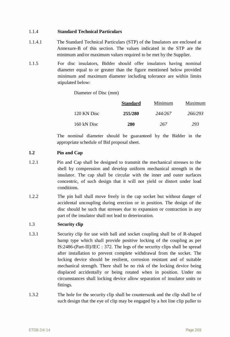
ETD8-24/14 Page 269
1.1.4 Standard Technical Particulars
1.1.4.1 The Standard Technical Particulars (STP) of the Insulators are enclosed at Annexure-B of this section. The values indicated in the STP are the minimum and/or maximum values required to be met by the Supplier.
1.1.5 For disc insulators, Bidder should offer insulators having nominal diameter equal to or greater than the figure mentioned below provided minimum and maximum diameter including tolerance are within limits stipulated below:
Diameter of Disc (mm)
Standard Minimum Maximum
120 KN Disc 255/280 244/267 266/293
160 kN Disc 280 267 293
The nominal diameter should be guaranteed by the Bidder in the appropriate schedule of Bid proposal sheet.
1.2 Pin and Cap
1.2.1 Pin and Cap shall be designed to transmit the mechanical stresses to the shell by compression and develop uniform mechanical strength in the insulator. The cap shall be circular with the inner and outer surfaces concentric, of such design that it will not yield or distort under load conditions.
1.2.2 The pin ball shall move freely in the cap socket but without danger of accidental uncoupling during erection or in position. The design of the disc should be such that stresses due to expansion or contraction in any part of the insulator shall not lead to deterioration.
1.3 Security clip
1.3.1 Security clip for use with ball and socket coupling shall be of R-shaped hump type which shall provide positive locking of the coupling as per IS:2486-(Part-Ill)/IEC : 372. The legs of the security clips shall be spread after installation to prevent complete withdrawal from the socket. The locking device should be resilient, corrosion resistant and of suitable mechanical strength. There shall be no risk of the locking device being displaced accidentally or being rotated when in position. Under no circumstances shall locking device allow separation of insulator units or fittings.
1.3.2 The hole for the security clip shall be countersunk and the clip shall be of such design that the eye of clip may be engaged by a hot line clip puller to

ETD8-24/14 Page 270
provide for disengagement under energised conditions. The force required to pull the security clip into its unlocked position shall not be less than 50N (5 kg) or more than 500N (50 kg).
1.4 Ball and Socket Designation
The dimensions of the balls and sockets shall be of 20 mm designation for 120 KN & 160 KN disc in accordance with the standard dimensions stated in IS:2486 - (Part - II)/IEC:120.
1.5 Dimensional Tolerance of Insulator Disc (Standard)
It shall be ensured that the dimensions of the disc insulators are within the limits specified below :
Ball to ball spacing between discs
Standard Minimum Maximum
120 KN Disc 145 141 149
160 kN Disc 170 165 175
1.6 Interchangeability
The disc insulators inclusive of the ball and socket fittings shall be of standard design suitable for use with the hardware fittings of any make conforming to relevant Indian/International Standards.
1.7 Corona And RI Performance
All surfaces must be clean, smooth, without cuts, abrasions or projections. No part shall be subjected to excessive localised pressure. The metal parts shall be so designed and manufactured that it shall not generate any Radio Interference beyond specified limit and not produce any noise generating corona under the operating conditions.
1.8 Maintenance
1.8.1 The disc insulators offered shall be suitable for employment of hot line maintenance techniques so that the usual hot line operations can be carried out with ease, speed and safety.
1.8.2 Bidders shall indicate the methods generally used in the routine hot and dead line maintenance of EHV Lines for which similar disc insulators have been supplied by them. Bidders shall also indicate the recommended periodicity of such maintenance.
1.9 Materials
1.9.1 Porcelain

ETD8-24/14 Page 271
The porcelain used in the manufacture of shells shall be sound, free from defects thoroughly vitrified and smoothly glazed.
1.9.2 Glaze
The finished porcelain shall be glazed in brown colour. The glaze shall cover all exposed parts of the insulator and shall have a good lusture, smooth surface and good performance under the extreme weather conditions of a tropical climate. It shall not crack or chip by ageing under the normal service conditions. The glaze shall have the same coefficient of expansion as of the porcelain body throughout the working temperature range.
1.9.3 Toughened Glass
The glass used for the shells shall be sound, free from defects such as flaws. bubbles, inclusions etc. and be of uniform toughness over its entire surface. All exposed glass surfaces shall be smooth.
1.9.4 Cement
Cement used in the manufacture of the insulator shall not cause fracture by expansion or loosening by contraction. The cement shall not give rise to chemical reaction with metal fittings and its thickness shall be as small and uniform as possible. Proper care shall be taken to correctly centre and locate individual parts during cementing.
1.9.5 Pins and Caps
Pins and Caps shall be made of drop forged steel and malleable cast iron/spheriodal graphite iron/drop forges steel respectively, duly hot dip galvanised and shall not be made by jointing, welding, shrink fitting or any other process from more than one piece of material.
1.9.6 Security Clips
Security clips shall be made of good quality stainless steel or phosphor bronze as per IS:1385. 2.5% extra Security clip shall be provided.
1.10 Workmanship
1.10.1 All the material shall be of the latest design and conform to the best modern practices adopted in the extra high voltage field. Suppliers shall offer only such insulators as are guaranteed by him to be satisfactory and suitable for 400 kV Transmission line and will give continued good service.
1.10.2 The design, manufacturing process and material control at various stages shall be such as to give maximum working load, highest mobility, best

ETD8-24/14 Page 272
resistance to corrosion, good finish and elimination of sharp edges and corners to limit corona and radio interference.
1.10.3 The design of the insulators shall be such that stresses due to expansion and contraction in any part of the insulator shall not lead to deterioration.
1.10.4 Metal caps shall be free from cracks, seams, shrinks, air holes, burrs and rough edges. All surfaces of the metal parts shall be perfectly smooth with no projecting points or irregularities which may cause corona. All load bearing surfaces shall be smooth and uniform so as to distribute the loading stresses uniformly.
1.10.5 All ferrous parts shall be hot dip galvanised to give a minimum average coating of Zinc equivalent to 600 gm/sq.m. and shall be in accordance with the requirement of IS:2629 and shall satisfy the tests mentioned in IS:2633. The zinc used for galvanising shall be of Grade Zn 99.95 as per IS:209. The zinc coating shall be uniform, adherent, smooth, reasonably bright, continuous and free from imperfections such as flux, ash, rust stains, bulky white deposits and blisters. The galvanised metal parts shall be guaranteed to withstand atleast six successive dips each lasting for one (1) minute duration under the standard preece test.
1.10.6 Before ball fittings are galvanised, all die flashing on the shank surface of the ball shall be carefully removed without reducing the dimensions below the design requirements.
1.10.7 The design of the insulators shall be such that the shell shall not engage directly with hard metal. The design shall also be such that when units are coupled together there is no contact between the shell of one unit and metal of the next adjacent unit. The design of the shell ribs shall be such that the security clip of the insulator can be engaged and disengaged easily with hot stick without damaging the shell ribs.
1.10.8 Insulator units after assembly shall be concentric and co-axial within limits as permitted by the relevant Indian Standards.
1.10.9 The manufacturer of the insulators shall guarantee an insulator failure rate not exceeding 1 (one) per 10000 (ten thousand) per year for disc insulator per year. In case the annual failure rate during the first ten years of service exceeds the above figure, under normal operating condition, as will be determined by check to be conducted as per mutually agreed procedure and conditions upto ten years, (as permitted by the operating situation), the Supplier shall supply to the Owner free of cost spare insulators equal to 10 time the excess failure.
1.10.10 The Supplier shall guarantee that there shall not be any decapping/breaking of insulators on line under normal operating conditions. In the event of any decapping/breaking and subsequent line

ETD8-24/14 Page 273
drop, during the first ten years of service the Supplier shall have to pay Rs. 50,000/- (Rs. Fifty thousand only) per dropped string towards expenditure to be incurred by POWERGRID for this line repair.
2.0 Equipment Marking
2.1 Each insulator disc/long rod unit shall be legibly and indelibly marked with the trade mark of the manufacturer, name of POWERGRID/PG and month & year of manufacture. The guaranteed combined mechanical and electrical strength shall be indicated in kilo Newton followed by the word ‘kN’ to facilitate easy identification and to ensure proper use.
2.2 For porcelain insulator, the marking shall be on porcelain. The marking shall be printed, not impressed and shall be applied before firing. For toughened glass insulators the marking shall be on the metal parts.
2.3 One 10 mm thick ring or 20 mm thick spot of suitable quality of paint shall be marked on the cap of each insulator porcelain disc/porcelain long rod of particular strength for easy identification of the type of insulator. The paint shall not have any deteriorating effect on the insulator performance. Following codes shall be used as identification mark :
For 120 kN disc/ long rod unit : Yellow
For 160 kN disc / long rod unit : Green
3.0 Bid Drawings
3.1 The Bidder shall furnish full description and illustration of the material offered.
3.2 The Bidder shall furnish along with the bid the outline drawing (6 copies) of each insulator unit including a cross sectional view of the insulator shell. The drawing shall include but not limited to the following information :
(a) Shell diameter and ball to ball spacing with manufacturing tolerances
(b) Minimum Creepage distance with positive tolerance
(c) Protected creepage distance
(d) Eccentricity of the disc
(i) Axial run out
(ii) Radial run out
(e) Unit mechanical and electrical characteristics
(f) Size and weight of ball and socket parts

ETD8-24/14 Page 274
(g) Weight of unit insulator disc/long rod units
(h) Materials
(i) Identification mark
(j) Manufacturer's catalogue number
3.3 After placement of award, the Supplier shall submit full dimensioned insulator drawings containing all the details as given in Clause No. 4.2 above, in four (4) copies to Owner for approval. After getting approval from Owner and successful completion of all the type tests, the Supplier shall submit 20 more copies of the same drawing to the Owner for further distribution and field use at Owner's end.
3.4 After placement of award the Supplier shall also submit fully dimensioned insulator crate drawing for different type of insulators.
3.5 After placement of award, the Supplier shall submit full dimensioned manufacturing drawing of insulator cap, pin and insulator shell in six (6) copies to the Owner for reference and record.
4.0 Tests and Standards
4.1 Type Tests
The following type tests shall be conducted on a suitable number of individual standard disc insulators or long rod units, components, materials or complete strings:
4.1.1 On unit disc Insulators
a) Visual examination IS:731-1971
b) Verification of dimensions and axial & radial runout
As per IEC60383 & Annexure -.A
c) Total creepage distance measurement -do
d) Electromechanical failing load test -do-
e) Puncture test IS:731-1971
f) Porosity test -do-
g) Galvanizing test -do-
h) Power frequency Voltage withstand test
i)Dry ii) Wet
IEC:60383

ETD8-24/14 Page 275
i) Power frequency Voltage flashover test
i)Dry ii) Wet
-do
j) Impulse voltage withstand test (dry) -do-
k) Impulse voltage flashover test (dry) -do-
l) Visible Discharge test (dry) IS:731, Cl. 10.2
m) RIV test(dry) IEC:60437
n) Metallurgical tests on metallic parts Annexure -.A
o) Thermal mechanical test and Mechanical performance test
-do-
p) Steep wave front test -do-
q) Test on locking devices for ball & socket coupling
IEC: 372
r) Temperature cycle test IS:731
s) 24 hours mechanical strength test -do-
t) Power are test Annexure -.A
u) Verification of the locking system IEC: 60383
v) Residual strength test Annexure -A
w) Impact test Annexure -A
4.1.2 On the complete Disc Insulator String with Hardware Fittings for 400 kV lines
String on which Test is to be conducted
a) Visual examination IS:731-1971
SIS,SISP, ST,DIS,DT, QT
b) Assembly test Annexure -A
c) Verification of string length -do-
d) Power frequency voltage withstand test with corona control rings/ grading ring and arcing horn under wet
IEC:60383

ETD8-24/14 Page 276
condition
e) Switching surge voltage withstand test under wet condition
-do-
f) Impulse voltage withstand test under dry condition
-do-
g) Impulse voltage flashover test under dry condition
-do
h) Voltage distribution test Annexure -A
i) Mechanical strength test -do-
j) Pollution withstand voltage test
-do-
k) Corona and RIV test under dry condition
-do- SIS,SISP,ST, DIS,DT, QT
l) Vibration test SIS,DIS,DT, QT
m) Power Arc Test -do- SIS, DIS,DT, QT
4.1.3 The type tests should have either been conducted in accredited laboratory (accredited based on ISO/IEC vide 25/17025 or EN 45001 by the National accreditation body of the country where laboratory is located) or witnessed by the representative(s) of POWERGRID or utility. The test reports submitted shall be for the tests conducted within last 5 (five) years prior to date of bid opening.
4.1.4 In case any of the above type tests have not been conducted or the tests have been conducted earlier than the above stipulated period of 5 years or in the event of any discrepancy in the test report (i.e., any test not applicable due to any design/manufacturing change including substitution of components or due to non-compliance with the requirement stipulated in the Technical Specifications), the tests shall be conducted by the Supplier in the presence of purchaser’s representative at no extra cost to the Purchaser.
4.2 Acceptance Tests
4.2.1 For Disc Insulators (Both porcelain and glass)

ETD8-24/14 Page 277
a) Visual examination : As per IEC : 60383
b) Verification of dimensions : As per IEC : 60383
c) Verification of axial & radial runout Annexure -A
d) Temperature cycle test : As per IEC : 60383
e) Electromechanical failing load test Annexure -A
f) 24 Hours mechanical test IS731 – 1971/IEC 575
g) Puncture test IS : 731
h) Porosity test - do -
i) Galvanising test IEC : 60383
j) Mechanical performance test : As per IEC:60575Cl 4.0
k) Test on locking device for ball and socket coupling
: As per IEC:60372
l) Eccentricity test IEC : 60383
m) Residual Strength Test IEC : 797
Clause 4.4 & 4.5
n) Metallurgical Test (For metal fittings only in black condition)
Annexure-A
i) Grain size
ii) Inclusion rating
iii) Chemical analysis
iv) Microstructure
o) Chemical analysis of Zinc Sleeve Annexure -A.
p) IR Measurement Annexure –A
q) Impact Test Annexure –A
r) Verification of locking system IEC : 383 – 1993

ETD8-24/14 Page 278
s) Steep Wave front test Annexure-A
t) Thermal Mechanical performance test Annexure -A
4.2.2 For Glass Insulators Only
a) Thermal shock test : IEC : 60383
b) Steep wave front test/Puncture test Annexure -A
c) Mechanical failing load Test Annexure -A.
4.3 Routine Tests
4.3.1 For Disc Insulators
a) Visual Inspection : IS:731, Cl. 10.13
/ IEC : 383 ( Part – 1 ) 1993
b) Mechanical routine test : IS:731 Cl. 10.14
c) Electrical routine test (for porcelain disc insulator only)
: IS:731 Cl. 10.15
d) Thermal shock routine test (for glass insulator only)
: IEC:60383
e) Polarised Light Inspection (for glass insulator only)
Annexure -A
4.4 Tests During Manufacture
On all components as applicable
a) Chemical analysis of zinc used for galvanising Annexure –A
b) Chemical analysis, mechanical, metallographic test and magnetic particle inspection for malleable castings.
Annexure –A
c) Chemical analysis hardness tests and magnetic particle inspection for forgings
Annexure –A
d) Hydraulic Internal Pressure tests on disc insulator shells
Annexure –A

ETD8-24/14 Page 279
e) Autoclave Test on Cement Annexure –A
f) Crack detection tests before assembly Annexure -A
4.5.5 Bidder/Supplier shall indicate the laboratories in which they propose to conduct the type tests if required .They shall ensure that adequate facilities are available in the laboratory. The Supplier shall intimate the Purchaser about carrying out of the type tests alongwith detailed testing programme at least 3 weeks in advance (in case of Domestic Supplier) and at least 6 weeks advance (in case of foreign Supplier) of the scheduled date of testing during which the Purchaser will arrange to depute his representative to be present at the time of carrying out the tests.
4.5.6 The entire cost of testing for type, acceptance and routine tests and tests during manufacture specified herein shall be treated as included in the quoted Price.
4.5.7 In case of failure in any type test, if repeat type tests are required to be conducted, then all the expenses for deputation of Inspector/ Purchaser's representative shall be deducted from the contract price. Also if on receipt of the Supplier's notice of testing, the Purchaser's representative does not find 'plant' to be ready for testing the expenses incurred by the Purchaser for redeputation shall be deducted from contract price.
4.6 Sample Batch for Type Testing
4.6.1 The Supplier shall offer material for sample selection for type testing only after getting Quality Assurance Programme approved by the Purchaser. The Supplier shall offer at least three times the quantity of materials required for conducting all the type tests for sample selection. The sample for type testing will be manufactured strictly in accordance with the Quality Assurance Programme approved by the Purchaser.
4.6.2 Before sample selection for type testing, the Supplier shall be required to conduct all the acceptance tests successfully in presence of Purchaser's representative.
4.7 Repeat E&M Strength Test
4.7.1 E&M test on 20 nos. for disc insulator of samples for every lot of 10,000 nos. received at site shall be conducted. Testing expenses have to be borne by the Supplier and shall be included in quoted prices. Incase of failure, it will be repeated on double no. of samples and if it again fails, the whole lot should be rejected and shall be replaced by the Supplier. The samples have to be taken at random after segregating insulators damaged in transportation or otherwise.

ETD8-24/14 Page 280
4.7.2 The Purchaser reserves the right of having at his own expenses any other test(s) of reasonable nature carried out at Supplier's premises, at site, or in any other place in addition to the aforesaid type, acceptance and routine tests to satisfy himself that the material comply with the Specifications.
4.7.3 The Purchaser also reserves the right to conduct all the tests mentioned in this specification at his own expense on the samples drawn from the site at Supplier's premises or at any other test centre. In case of evidence of non compliance, it shall be binding on the part of the Supplier to prove the compliance of the items to the technical specifications by repeat tests or correction of deficiencies or replacement of defective items, all without any extra cost to the Purchaser.
4.8 Co-ordination for Testing
The Supplier shall have to co-ordinate testing of insulators with hardware fittings to be supplied by other Supplier and shall have to guarantee overall satisfactory performance of the insulators with the hardware fittings.
4.9 Guarantee
The Supplier of insulators shall guarantee overall satisfactory performance of the insulators with the hardware fittings.
4.10 Test Reports
4.10.1 Copies of type test reports shall be furnished in at least six (6) copies along with one original. One copy shall be returned duly certified by the Purchaser only after which the commercial production of the concerned material shall start.
4.10.2 Copies of acceptance test reports shall be furnished in at least six (6) copies. One copy shall be returned duly certified by the Purchaser, only after which the material shall be dispatched.
4.10.3 Record of routine test reports shall be maintained by the Supplier at his works for periodic inspection by the Purchaser’s representative.
4.10.4 Test certificates of test during manufacture shall be maintained by the Supplier. These shall be produced for verification as and when desired by the Purchaser.
4.11 Inspection
4.11.1 The Purchaser’s representative shall at all times be entitled to have access to the works and all places of manufacture, where insulator, and its component parts shall be manufactured and the representatives shall have full facilities for unrestricted inspection of the Supplier’s and sub-Supplier’s works, raw materials, manufacture of the material and for conducting necessary test as detailed herein.

ETD8-24/14 Page 281
4.11.2 The material for final inspection shall be offered by the Supplier only under packed condition as detailed under clause for ‘packing and marking’ in the specification. The Purchaser shall select samples at random from the packed lot for carrying out acceptance tests. Disc Insulators shall normally be offered for inspection in lots not exceeding 10,000 nos. The lot should be homogeneous and should contain insulators manufactured in 3-4 consecutive weeks.
4.11.3 The Supplier shall keep the Purchaser informed in advance of the time of starting and the progress of manufacture of material in their various stages so that arrangements could be made for inspection.
4.12.4 No material shall be dispatched from its point of manufacture before it has been satisfactorily inspected and tested unless the inspection is waived off by the Purchaser in writing. In the latter case also the material shall be dispatched only after satisfactory testing for all tests specified herein have been completed.
4.11.5 The acceptance of any quantity of material shall be no way relieve the Supplier of his responsibility for meeting all the requirements of the specification and shall not prevent subsequent rejection, if such material are later found to be defective.
4.12 Packing and Marking
4.12.1 All insulators shall be packed in strong seasoned wooden crates. The gross weight of the crates along with the material shall not normally exceed 200 Kg to avoid handling problem. For marine transportation crates shall be palleted.
4.12.2 The packing shall be of sufficient strength to withstand rough handling during transit, storage at site and subsequent handling in the field.
4.12.3 Suitable cushioning, protective padding, or dunnage or spacers shall be provided to prevent damage or deformation during transit and handling.
4.12.4 All packing cases shall be marked legibly and correctly so as to ensure safe arrival at their destination and to avoid the possibility of goods being lost or wrongly dispatched on account of faulty packing and faulty or illegible markings. Each wooden case/crate shall have all the markings stenciled on it in indeliable ink.
4.13 Standards
The insulator strings and its components shall conform to the following Indian/ International Standards which shall mean latest revision, with amendments/changes adopted and published, unless specifically stated otherwise in the Specification.

ETD8-24/14 Page 282
Indian Standard
Title International Standard
1. IS:209-1992 Specification for zinc BS:3436
2. IS:406-1991 Method of Chemical Analysis of Slab Zinc
BS:3436
3. IS:731-1991 Porcelain insulators for overhead Power lines with a nominal voltage greater than 1000 V
BS:137- (I&II) IEC:60383
4. IS:2071 Part (I) – 1993 (Part(II)- 1991 Part(III)- 1991
Methods of High Voltage Testing IEC:60060-1
5. IS:2486
Part- I-1993
Part- II-1989
Part-III-1991
Specification for Insulator fittings for Overhead Power Lines with a nominal voltage greater than 1000V
General Requirements and Tests Dimensional Requirements
Locking Devices
BS:3288
IEC:60120
IEC:60372
6. IS:2629-1990 Recommended Practice for Hot, Dip Galvanisation for iron and steel
ISO-1461 (E)
7. IS:2633-1992 Testing of Uniformity of Coating of zinc coated articles
8. IS:3188-1988 Dimensions for Disc Insulators IEC:60305
9. IS:6745-1990 Determination of Weight of Zinc Coating on Zinc coated iron and steel articles
BS:433-1969 ISO:1460-1973
10. IS:8263-1990 Methods of RI Test of HV insulators IEC:60437
NEMA Publi- cation No.07/ 1964/ CISPR
11. IS:8269-1990 Methods for Switching Impulse test on HV insulators
IEC:60506

ETD8-24/14 Page 283
12. Thermal Mechanical Performance test and mechanical performance test on string insulator units
IEC: 60575
13. Salt Fog Pollution Voltage Withstand Test
IEC:60507
14. Residual Strength of String Insulator Units of Glass or Ceramic Material for Overhead Lines after Mechanical Damage of the Dielectric
IEC:60797
15. Guide for the selection of insulators in respect of polluted conditions
IEC:60815
16. Tests on insulators of Ceramic material or glass or glass for overhead lines with a nominal voltage greater than 1000V
IEC:60383
17. Characteristics of string insulator units of the long rod type
IEC : 60433
18. Standard Test Method for Autoclave Expansion of Portland Cement
ASTM C151-93-a
19. American National Standard for Insulators wet process porcelain and toughened glass suspension type
ANSI C29-2-1992
The standards mentioned above are available from:
Reference Abbreviation
Name and Address
BS British Standards,
British Standards Institution
101, Pentonvile Road,
N - 19-ND
UK
IEC/CISPR International Electro technical Commission,
ETD8-24/14 Page 284
Bureau Central de la Commission,
electro Technique international,
1 Rue de verembe,
Geneva
SWITZERLAND
BIS/IS Beureau Of Indian Standards.
Manak Bhavan,
9, Bahadur Shah Zafar Marg,
New Delhi - 110001.
INDIA
ISO International Organisation for Standardization.
Danish Board of Standardization
Danish Standardizing Sraat,
Aurehoegvej-12
DK-2900, Heeleprup,
DENMARK.
NEMA National Electric Manufacture Association,
155, East 44th Street.
New York, NY 10017
U.S.A.
ASTM American Society for Testing and Materials,
1916 Race St. Phelledelphia, PA19103 USA

ETD8-24/14 Page 285
ANNEXURE-A
1. Tests on Complete Strings with Hardware Fittings
1.1 Assembly Test:
This test shall be carried out to ensure that cotter pins, bolts, clamps etc. fit freely and properly.
1.2 Total Creepage Measurement Test:
The creepage distance of each unit shall be measured by applying a thin inextensible cord along the shortest distance from the inner metal fittings to the cord to be in contact with the external surface of the unit. The total creepage distance shall be obtained by adding the values obtained above for the relative units and shall be not less than the value nominated under ‘Minimum Total Creepage Distance.’
1.3 Voltage Distribution Test (For Disc Insulator strings only)
The voltage across each insulator unit shall be measured by sphere gap method. The result obtained shall be converted into percentage. The voltage across any disc shall not exceed 9% for suspension insulator strings and 10% for tension insulator strings
1.4 Corona Extinction Voltage Test (Dry)
The sample assembly when subjected to power frequency voltage shall have a corona extinction voltage of not less than 320 kV (rms) line to ground under dry condition. There shall be no evidence of corona on any part of the sample. The atmospheric condition during testing shall be recorded and the test results shall be accordingly corrected with suitable correction factor as stipulated in IEC : 383.
1.5 RIV Test (Dry)
Under the conditions as specified under (1.2) above, the insulator string along with complete hardware fittings shall have a radio interference voltage level below 1000 micro volts at one MHz when subjected to 50 Hz AC voltage of 305 kV line to ground under dry condition. The test procedure shall be in accordance with IS:8263/IEC : 437.
1.6 Mechanical Strength Test
The complete insulator string along with its hardware fitting excluding arcing horn, corona control ring, grading ring and suspension assembly/dead end assembly shall be subjected to a load equal to 50% of the specified minimum ultimate tensile strength (UTS) which shall be increased at a steady rate to 67% of the minimum UTS specified. The load shall be held for five minutes and then removed. After removal of the load, the string components shall not show any visual deformation and it shall be possible to disassemble them by hand. Hand tools may be used to, remove cotter pins and loosen the nuts initially. The string shall then be reassembled and loaded to 50% of UTS and the load shall be further increased at a steady rate till the specified minimum UTS and held for one

ETD8-24/14 Page 286
minute. No fracture should occur during this period. The applied load shall then be increased until the failing load is reached and the value recorded.
1.7 Vibration Test
The suspension string shall be tested in suspension mode, and tension string in tension mode itself in laboratory span of minimum 30 metres. In the case of suspension string a load equal to 600 kg shall be applied along the axis of the suspension string by means of turn buckle. The insulator string along with hardware fittings and two/four sub-conductors (each tensioned at 43 kN) shall be secured with clamps. The system shall be suitable to maintain constant tension on the conductor throughout the duration of the test. Vibration dampers shall not be used on the test span. The conductor shall be vertically vibrated at one of the resonance frequencies of the insulators string (more than 10 Hz) by means of vibration inducing equipment. The peak to peak displacement in mm of vibration at the antinode point, nearest to the string, shall be measured and the same shall
not be less than 1000/f1.8 where f is the frequency of vibration in cycles/sec. The insulator string shall be vibrated for not less than 10 million cycles without any failure. After the test the insulators shall be examined for looseness of pins and cap or any crack in the cement. The hardware shall be examined for looseness, fatigue failure and mechanical strength test. There shall be no deterioration of properties of hardware components and insulators after the vibration test. The insulators shall be subjected to the following tests as per relevant standards :
Tests Percentage of Percentage of units to be tested
Disc insulators Long rod insulators
a) Temperature cycle test followed by mechanical performance test 60 100
b) Puncture test/steep wave front test 40 -
1.8 Power - Arc Test
This test shall be performed on the complete string in accordance with IEC Technical Report IEC : 61467-1997 with the following test series :
Test circuit Short circuit current Number and duration of test B In = Isys = 40 KA Two of tn = 0.2s and one of tn = 0.5s
The acceptance criteria after the completion of test series shall be following.
a) Insulator separation not permitted.
b) Burning/melting of metal components, breakage of insulator sheds, glaze removal are permitted.
c) The complete insulator string alongwith its hardware fitting excluding arching horn, corona control ring/grading ring shall withstand 80% of UTS.

ETD8-24/14 Page 287
2. On Disc Insulator Units
2.1 Verification of Axial and Radial Runout of Insulator Units :
The verification of axial and radial runout of insulator units shall be carried out together with the verification of dimension as the acceptance test also. The axial and radial runout shall comply with the provisions of relevant standards when the unit is roated through 360 degrees.
2.2 Steep Wave Front Test (For Disc Insulator only)
Test following test shall be performed on 10 insulator units in case of disc insulators selected at random from the lot offered for selection of sample for type test.
a) Each insulator unit shall be subjected to five successive positive and negative impulse flashovers with a wave having minimum effective rate of rise of 2500 kV per microseconds.
b) Each unit shall then be subjected to three dry power frequency voltage flashovers.
Acceptance Criteria
An insulator shall be deemed to have met the requirement of this test if, having been successfully subjected to the ten impulse flashovers, the arithmetic mean of the three subsequent dry/power frequency voltage flashover values equals or exceeds 95% of the rated dry power frequency flashover voltage.
An insulator shall be deemed to have failed to meet the requirement of above testing if,
(a) It has not flash over when the oscillogram or peak voltage indicator shows a marked reduction in voltage.
or
(b) Any one of the subsequent three dry power frequency voltage flashover value is less than 80% of the value specified.
Failure of any one unit either in the steep wave front or subsequent low frequency voltage test shall cause for testing on double number of units.
2.3 Polarised Light Inspection (only for Glass Disc Insulator)
The disc insulator shall be held over a polarised light source and the stress lines viewed thereon. There shall be no uneven stress distribution in the toughened glass insulators. This shall be carried out on 100% glass shells.
2.4 Hydraulic Internal Pressure Test on Shells (only for Disc Insulator)
The test shall be carried out on 100% shells before assembly. The details regarding test will be as discussed and mutually agreed to by the Supplier and Owner in Quality Assurance Programme.

ETD8-24/14 Page 288
2.5 Thermal Mechanical Performance Test
Thermal Mechanical Performance Test shall be performed in accordance with IEC-60383-1 Clause 20 with the following modifications:
(1) The applied mechanical load during this test shall be 70% of the rated electromechanical or mechanical value.
(2) The acceptance criteria shall be
(a) X greater than or equal to R + 3S.
Where
X = Mean value of the individual mechanical failing load.
R = Rated electro-mechanical / mechanical failing load.
S = Standard deviation.
(b) The minimum sample size shall be taken as 20 for disc insulator units and 5 units for long rod units.
(c) The individual electromechanical failing load shall be at least equal to the rated value. Also puncture shall not occur before the ultimate fracture.
2.6 Electromechanical/Mechanical Failing Load Test
This test shall be performed in accordance with clause 18 and 19 of IEC 383 with the following acceptance
(i) X greater than or equal to R + 3S
Where
X = Mean value of the electro-mechanical/mechanical/ failing load.
R = Rated electro-mechanical / mechanical failing load.
S = Standard deviation.
(ii) The minimum sample size shall be taken as 20 for disc insulators units and 5 for long rod units. However, for larger lot size, IEC 591 shall be applicable.
(iii) The individual electro-mechanical/mechanical failing load shall be at least equal to the rated value. Also electrical puncture shall not occur before the ultimate fracture.
2.7 Residual Strength Test (For Disc Insulators only)
The above test shall be performed as per clause 4.4 and 4.5 of IEC 797 preceded by the temperature cycle test, on both glass and porcelain disc insulators. The Sample size shall be 25 and the evaluation of the results and acceptance criteria shall be as per clause No. 4.6 of IEC:797.

ETD8-24/14 Page 289
2.8 Chemical Analysis of Zinc Sleeve
The purity of the zinc used in zinc sleeve shall be tested as per IS:209. The purity of zinc shall not be less than 99.8%.
2.9 IR Measurements
IR measurement shall be carried out by the instrument operating at 1 kV DC. IR value when measured under fair weather condition, shall not be less than 50 M-ohm.
2.10 Impact Test
The Impact Test shall be carried out in accordance with ANSI-C-29.2 Clause 8.2.8 with the following modification.
The breaking point of the pendulum shall be so adjusted that, when released the copper nose will strike the outer rim of the shell or the most protuded rim of the shell squarely in a direction parallel to the axis of the unit and towards the cap.
The test specimen shall receive an impact of 7 N-m for 120 kN Disc insulators and 10N-m for 160 kN Disc Insulators, by releasing the pendulum.
3. Tests on All components (As applicable)
3.1 Chemical Analysis of Zinc used for Galvanizing
Samples taken from the zinc ingot shall be chemically analysed as per IS:209-1979. The purity of zinc shall not be less than 99.95%.
3.2 Tests for Forgings
The chemical analysis hardness tests and magnetic particle inspection for forgings, will be as per the internationally recognised procedures for these tests. The sampling will be based on heat number and heat treatment batch. The details regarding test will be as discussed and mutually agreed to by the Supplier and Owner in Quality Assurance Programme.
3.3 Tests on Castings
The chemical analysis, mechanical and metallographic tests and magnetic, particle inspection for castings will be as per the internationally recognised procedures for these tests. The samplings will be based on heat number and heat treatment batch. The details regarding test will be as discussed and mutually agreed to by the Supplier and Owner in Quality Assurance Programme.
3.4 Autoclave Test
For cement used in the assembly of the insulators six samples from different batches shall be tested in accordance with ASTM C-151. The cement shall have an expansion less than 0.12%.

ETD8-24/14 Page 290
ANNEXURE-B DESCRIPTION UNIT 120 KN 160KN GENERAL
Size and designation of ball and socket mm 20.0as per IS2486/IEC120 20.0as per
IS2486/IEC120 DIMENSIONS Disc insulator diameter mm 255.0 or 280.0 280.0 Tolerance of dia. ±mm 11.0(for 255.0)/13.0(for 280.0) 13.0 Ball to ball spacing between disc mm 145.0 170.0 Tolerance of spacing ±mm 4.0 5.0 Minimum Creepage distance of single disc mm 315.0 330.0 Colour of glaze of finished porcelain insulator NA Brown Brown ELECTRO-MECANICAL STRENGTH KN 120.0 160.0 MINIMUM ELECTRICAL VALUES Power frequency flashover voltage (dry) kV(rms) 75.0 78.0 Power frequency flashover voltage(wet) kV(rms) 45.0 48.0 Impulse flashover voltage positive (dry) kV peak 115.0 120.0 Impulse flashover voltage negative (dry) kV peak 120.0 125.0 Power frequency withstand voltage(dry) kV(rms) 70.0 72.0 Power frequency withstand voltage(wet) kV(rms) 40.0 42.0 Impulse withstand voltage positive (dry) kV peak 110.0 115.0 Impulse withstand voltage negative (dry) kV peak 110.0 115.0 Steepness of impulse voltage(steep wave front test) Kv/µs 2500.0 2500.0 POWER FREQUENCY PUNCTURE VOLTAGE kV(rms) 120.0 125.0 MIN VISIBLE DISCHARGE VOLTAGE OF SINGLE kV (rms) 18.0 18.0 DISC(DRY) MAX RIV AT 1MHz and 10 KV(rms) µV 50.0 50.0 No. of dips in standard preece test Nos (6 dips of 1min) (6 dips of 1min) ECCENTRICITY OF DISC Max radial runout mm 7.65(for 255.0)/8.40(for 280.0) 8.4 Max axial runout mm 10.20(for 255.0)/11.20(for 280.0) 11.2 MINIMUM MASS OF ZINC COATING gm/sq. m. 600 600 MINIMUM ZINC PURITY USED FOR GALVANIZING % 99.95% 99.95%
Insulator Strings with disc insulators

ETD8-24/14 Page 291
S.N
DESCRIPTION UNIT TWIN ACSR MOOSE CONDUCTOR
TWIN/QUAD ACSR MOOSE CONDUCTOR
QUAD ACSR MOOSE CONDUCTOR
Single 'I' Suspension string
Double Tension string
Single Suspension pilot string
Single Tension string
Double 'I' Suspension Pilot string
Quadrupple Tension string
(1 x 23) (2 x 23) (1 x 23) (1 x 24) ( 2 x 23) (4 x 23)
1.0 Power frequency kV(rms) 680 680 680 680 680 680 withstand voltage of string with arcing horns, corona control
rings/grading rings
under wet condition
2.0 Switching surge
withstand voltage(wet)
(a) Positive kV(peak) 1050 1050 1050 1050 1050 1050 (b) Negative kV(peak) 1050 1050 1050 1050 1050 1050
3.0 Impulse withstand
voltage(dry) (a) Positive kV(peak) 1550 1550 1550 1550 1550 1550 (b) Negative kV(peak) 1550 1550 1550 1550 1550 1550
4.0 Min. Impulse flashover
voltage(dry)* (a) Positive kV(peak) 1615 1615 1615 1615 1615 1615 (b) Negative kV(peak) 1615 1615 1615 1615 1615 1615
5.0 Minimum Corona kV(rms) 320 320 320 320 320 320 extinction voltage
under dry condition
6.0 RIV at 1MHZ when the
Microvolt
1000 (max.)
1000 (max.)
1000 (max.)
1000 (max.)
1000 (max.) 1000(max.)
string is energized at
305 Kv(rms) under dry
condition
7.0 Mechanical strength of kN 120 2 X 160 120 120 2 x 120 4 X 160
complete insulator
string alongwith hard-
ware fittings
8.0 Maximum voltage % 9 10 9 10 9 10
distribution across any
disc of line to earth
voltage
*As per IEC 60-1

ETD8-24/14 Page 292
Insulator Strings with Long rod insulators
S.N. DESCRIPTION UNIT TWIN ACSR MOOSE CONDUCTOR
TWIN/QUAD ACSR MOOSE CONDUCTOR
QUAD ACSR MOOSE CONDUCTOR
Single 'I' Suspension string
Double Tension string
Single Suspension pilot string
Single Tension string
Double 'I' Suspension Pilot string
Quadrupple Tension string
(1 x 23) (2 x 23) (1 x 23) (1 x 24) ( 2 x 23) (4 x 24)
1.0 Power frequency kV(rms) 680 680 680 680 680 680 withstand voltage of string with arcing horns, corona control rings/grading rings
under wet condition
2.0 Switching surge
withstand voltage(wet)
(a) Positive kV(peak) 1050 1050 1050 1050 1050 1050 (b) Negative kV(peak) 1050 1050 1050 1050 1050 1050
3.0 Impulse withstand voltage(dry)
(a) Positive kV(peak) 1550 1550 1550 1550 1550 1550 (b) Negative kV(peak) 1550 1550 1550 1550 1550 1550
4.0 Min. Impulse flashover
voltage(dry)* (a) Positive kV(peak) 1615 1615 1615 1615 1615 1615 (b) Negative kV(peak) 1615 1615 1615 1615 1615 1615
5.0 Minimum Corona kV(rms) 320 320 320 320 320 320 extinction voltage
under dry condition
6.0 RIV at 1MHZ when the Microvolt
1000 (max.)
1000 (max.)
1000 (max.)
1000 (max.)
1000 (max.)
1000 (max.)
string is energized at
305 Kv(rms) under dry
condition
7.0 Mechanical strength of kN 120 2 X 160 120 120 2 x 120 4 X 160
complete insulator
string alongwith hard-

ETD8-24/14 Page 293
ware fittings
8.0 Maximum voltage % 9 10 9 10 9 10
distribution across any
disc of line to earth
voltage
Double Tension string

ETD8-24/14 Page 294
SECTION-VI
TECHNICAL DESCRIPTION OF HARDWARE FITTINGS AND CONDUCTOR & EARTHWIRE
ACCESSORIES

ETD8-24/14 Page 295
TECHNICAL SPECIFICATION
SECTION - VI
1.0 Technical Description of Hardware Fittings
1.1 Details of Hardware Fittings
1.1.1 The hardware fittings shall be suitable for use with Disc insulators and /or porcelain long rod insulators having ball and socket fittings. The hardware fittings shall be as per the specification drawings enclosed with the section of drawing of the specification. Each hardware fitting shall be supplied complete in all respects and shall include the following hardware parts :
1.1.2 Suitable arcing horn as specified in clause 1.8 hereinafter.
1.1.3 Suitable yoke plates complying with the specifications given hereinafter.
1.1.4 Corona control rings/grading ring with fittings for attachment to line side yoke plate.
1.1.5 Sag adjustment plate for Quadruple tension hardware fittings and turn buckle for single tension hardware fittings.
1.1.6 Suspension and dead end assembly to suit conductor size as detailed in clause 1.13, 1.14 and 1.15 hereinafter.
1.1.7 Provisions for attaching balancing weights on the line side yoke plate of single suspension pilot hardware fittings.
1.1.8 Other necessary fittings viz D-shackles, eye links, extension links, ball clevis, socket clevis, clevis eye, U clevis and chain link etc. to make the hardware fittings complete.
1.1.9 2.5% extra fasteners .
1.2 Dimensions of Insulator String Along with Hardware Fitting
The various limiting dimensions of the insulator strings along with hardware fittings shall be as per the specification drawings enclosed in section of drawings of this specification.
1.2.1 For every set of quad-tension hardware fittings, one number 250 mm rigid spacer suitable for twin ACSR MOOSE conductor shall also be provided to ensure that there is no fouling of conductors or any component of the fittings while bringing down top two conductor through bottom two conductors of quad bundle, at the jumper connection.

ETD8-24/14 Page 296
1.3 Interchangeability
1.3.1 The hardware for insulator strings with disc insulators / porcelain long rod insulators together with ball and socket fittings shall be of standard design, so that these hardware are inter- changeable with each other and suitable for use with insulators of any make conforming to relevant Indian/International Standard.
1.4 Corona and RI Performance
Sharp edges and scratches on all the hardware fittings shall be avoided. All surfaces must be clean, smooth, without cuts and abrasions or projections. The
Contractor must give suitable assurance about the satisfactory corona and radio interference performance of the materials offered by him.
1.5 Maintenance
1.5.1 The hardware fittings offered shall be suitable for employment of hot line maintenance technique so that usual hot line operations can be carried out with ease, speed and safety. The technique adopted for hot line maintenance shall be generally bare hand method & hot stick method. The Bidder should clearly establish in the bid, the suitability of his fittings for hot line maintenance.
1.5.2 The line side yoke plate shall have a notch & a working hole of suitable size. The design of corona control rings/grading ring shall be such that it can be easily replaced by employing hot line maintenance technique.
1.6 Designation
1.6.1 Ball and Socket Designation
The dimensions of the ball and socket are furnished in section–I of this Specification. The designation should be in accordance with the standard dimensions stated in IS:2486-(Part-II)/IEC:120. The dimensions shall be checked by the appropriate gauge after galvanizing only.
1.7 Security Clips and Split Pins
1.7.1 Security clips for use with ball and socket coupling shall be R-shaped, hump type which provides positive locking of the coupling as per IS:2486-(Part-III)/ IEC : 372. The legs of the security clips shall be spread after assembly in the works to prevent complete withdrawal from the socket. The locking device should be resilient, corrosion resistant and of suitable mechanical strength. There shall be no risk of the locking device being displaced accidentally or

ETD8-24/14 Page 297
being rotated when in position. Under no circumstances shall the locking devices allow, separation of fittings.
1.7.2 The hole for the security clip shall be countersunk and the clip should be of such design that the eye of clip may be engaged by a hot line clip puller to provide for disengagement under energised conditions. The force required to pull the security clip into its unlocked position shall not be less than 50 N (5 kg) or more than 500 N (50 kg).
1.7.3 Split pins shall be used with bolts & nuts.
1.8 Arcing Horn/Intermediate Arcing Horn
1.8.1 The arcing horn / Intermediate Arcing Horn shall be either ball ended rod type or tubular type.
1.8.2 The arcing horn shall be provided as shown on the drawing of the hardware fittings, in this specification.
1.8.3 The air gap shall be so adjusted to ensure effective operation under actual field conditions.
1.9 Yoke Plates
The strength of yoke plates shall be adequate to withstand the minimum ultimate tensile strength as specified in the bid drawings.
The plates shall be either triangular or rectangular in shape as may be necessary. The design of yoke plate shall take into account the most unfavorable loading conditions likely to be experienced as a result of dimensional tolerances for disc insulators as well as components of hardware fittings within the specified range. The plates shall have suitable holes for fixing corona control rings/grading ring/arcing horn. All the corners and edges should be rounded off with a radius of at least 3 mm. Design calculations i.e. for bearing & tensile strength, for deciding the dimensions of yoke plate shall be furnished by the bidder. The holes provided for bolts in the yoke plate should satisfy shear edge condition as per Clause No. 8.10 of IS:800-1984..
1.10 Corona Control Rings/Grading Ring
1.10.1 The Corona control rings/grading ring shall be provided with hardware fittings and shall be of such design that it should cover at least one disc insulator in disc insulator strings so that they will reduce the voltage across the insulator units. It shall also improve corona and radio interference performance of the complete insulator string along with hardware fittings.

ETD8-24/14 Page 298
1.10.2 The corona control rings/grading ring shall be made of high strength heat treated aluminium alloy tube of minimum 2.5 mm wall thickness. If mild steel brackets are used then the brackets shall not be welded to the pipe but shall be fixed by means of bolts and nuts on a small aluminium plate attachment welded to the pipe. The welded center of the corona control ring/grading ring shall be grinded before buffing. Alternately, Aluminium tube/flats of suitable dimensions welded to the corona control rings/grading rings may be used for connection to yoke plate.
1.10.3 The Corona control rings/grading ring should have a brushed satin finish and not a bright glossy surface. No blemish should be seen or felt when rubbing a hand over the metal.
1.10.4 The limiting dimensions of corona control ring shall be as per the specification drawings.
1.10.5 Bidder may quote for grading ring with armour grip suspension assembly. The grading ring shall be of open type design with a gap of 125 mm. The open ends shall be suitably terminated. The outside diameter of the tube shall be 60 mm. The ends of grading ring tube shall be sealed with welded aluminium cap duly buffed.
1.11 Sag Adjustment Plate
1.11.1 The sag-adjustment plate to be provided with the Quad tension hardware fitting shall be of three plate type. The sag adjustment plate shall be provided with a safety locking arrangement. The device shall be of such design that the adjustment is done with ease, speed and safety.
1.11.2 The maximum length of the sag adjustment plate from the connecting part of the rest of the hardware fittings shall be 520 mm. The details of the minimum and maximum adjustment possible and the steps of adjustment shall be clearly indicated in the drawing. An adjustment of 150 mm minimum at the interval of 6 mm shall be possible with the sag adjustment plate.
1.11.3 Design calculations for deciding the dimensions of sag adjustment plate shall be furnished by bidder. The hole provided for bolts should satisfy shear edge condition as per Clause No.8.10 of IS:800-1984.
1.12 Turn Buckle
1.12.1 The turn buckle is to be provided with single tension hardware fitting. The threads shall be of sufficient strength to remain unaffected under the specified tensile load.

ETD8-24/14 Page 299
1.12.2 The maximum length of the turn buckle from the connecting part of the rest of the hardware fittings shall be 520 mm. The details of the minimum and maximum adjustment possible shall be clearly indicated in the drawing. An adjustment of 150 mm minimum shall be possible with turn buckle.
1.13 Suspension Assembly
1.13.1 The suspension assembly shall be suitable for the specific conductor as given in Section–I of this Specification.
1.13.2 The suspension assembly shall include free center type suspension clamp along with standard preformed armour rods or armour grip suspension clamp; except for Pilot insulator string for which only suitable Envelope type suspension clamp shall be used.
1.13.3 The suspension clamp along with standard preformed armour rods set shall be designed to have maximum mobility in any direction and minimum moment of inertia so as to have minimum stress on the conductor in the case of oscillation of the same.
1.13.4 The suspension clamp along with standard preformed armour rods/armour grip suspension clamp set shall have the slip strength not less than that specified in the Standard Technical Particulars.
1.13.5 The suspension assembly shall be designed, manufactured and finished to give it a suitable shape, so as to avoid any possibility of hammering between suspension assembly and conductor due to vibration. The suspension assembly shall be smooth without any cuts, grooves, abrasions, projections, ridges or excrescence, which might damage the conductor.
1.13.6 The suspension assembly/clamp shall be designed so that it shall minimise the static & dynamic stress developed in the conductor under various loading conditions as well as during wind induced conductor vibrations. It shall also withstand power arcs & have required level of Corona/RIV performance.
1.13.7 The magnetic power loss shall not be more than that stipulated in the Standard Technical Particulars.
1.13.8 Free Center Type Suspension Clamp
For the Free Center Suspension Clamp seat shall be smoothly rounded and curved into a bell mouth at the ends. The lip edges shall have rounded bead. There shall be at least two U-bolts for tightening of clamp body and keeper pieces together.

ETD8-24/14 Page 300
1.13.10 Standard Preformed Armour Rod Set
1.13.10.1 The Preformed Armour Rods Set, suitable for specific Conductor, shall be used to minimise the stress developed in the sub-conductor due to different static and dynamic loads because of vibration due to wind, slipping of conductor from the suspension clamp as a result of unbalanced conductor tension in adjacent spans and broken wire condition. It shall also withstand power arcs. chafing and abrasion from suspension clamp and localised heating effect due to magnetic power losses from suspension clamps as well as resistance losses of the conductor.
1.13.10.2 The preformed armour rods set shall have right hand lay and the inside diameter of the helics shall be less than the outside diameter of the conductor to have gentle but permanent grip on the conductor. The surface of the armour rod when fitted on the conductor shall be smooth and free from projections, cuts and abrasions etc.
1.13.10.3 The pitch length of the rods shall be determined by the Bidder but shall be less than that of the outer layer of conductor and the same shall be accurately controlled to maintain uniformity and consistently reproducible characteristic wholly independent of the skill of linemen.
1.13.10.4 The length of each rod along with permissible tolerances shall be as stipulated in the Standard Technical Particulars. The end of armour rod shall be parrot billed.
1.13.10.5 The number of armour rods in each set shall as stipulated in the Standard Technical Particulars. Each rod shall be marked in the middle with paint for easy application on the line.
1.13.10.6 The armour rod shall not loose their resilience even after five applications.
1.13.10.7 The conductivity of each rod of the set shall not be less than 40% of the conductivity of the International Annealed Copper Standard (IACS).
1.13.11 Armour Grip Suspension Clamp
1.13.11.1 The armour grip suspension clamp shall comprise of retaining strap, support housing, elastomer inserts with aluminium reinforcements and AGS preformed rod set.
1.13.11.2 Elastomer insert shall be resistant to the effects of temperature up to 95oC, Ozone, ultraviolet radiations and other atmospheric contaminants likely to be encountered in service. The physical properties of the elastomer shall be of approved standard. It shall be electrically shielded by a cage of AGS

ETD8-24/14 Page 301
performed rod set. The elastomer insert shall be so designed that the curvature of the AGS rod shall follow the contour of the neoprene insert.
1.13.11.3 The AGS preformed rod set shall be as detailed in clause 1.13.10.4 to 1.13.10.7 in general except for the following.
1.13.11.4 The length of the AGS preformed rods shall be such that it shall ensure sufficient slipping strength as detailed under clause 1.13.4 and shall not introduce unfavorable stress on the conductor under all operating conditions. However the length of AGS preformed rods shall not be less than that stipulated in the Standard Technical Particulars.
1.14 Envelope Type Suspension Clamp
1.14.1 The seat of the envelope type suspension clamp shall be smoothly rounded & suitably curved at the ends. The lip edges shall have rounded bead. There shall be at least two U-bolts for tightening of clamp body and keeper pieces together. Hexagonal bolts and nuts with split-pins shall be used for attachment of the clamp.
1.15 Dead end Assembly
1.15.1 The dead end assembly shall be suitable for specific Conductor.
1.15.2 The dead end assembly shall be compression type with provision for comprising jumper terminal at one end. The angle of jumper terminal to be mounted should be 30° with respect to the vertical line. The area of bearing surface on all the connections shall be sufficient to ensure positive electrical
and mechanical contact and avoid local heating due to I2R losses. The resistance of the clamp when compressed on Conductor shall not be more than 75% of the resistance of equivalent length of Conductor.
1.15.3 Die compression areas shall be clearly marked on each dead-end assembly designed for continuous die compressions and shall bear the words ‘COM PRESS FIRST’ suitably inscribed near the point on each assembly where the compression begins. If the dead end assembly is designed for intermittent die compressions it shall bear identification marks ‘COMPRESSION ZONE’ AND ‘NON-COMPRESSION ZONE’ distinctly with arrow marks showing the direction of compressions and knurling marks showing the end of the zones. The letters, number and other markings on the finished clamp shall be distinct and legible. The dimensional tolerances of the cross section of aluminium and steel dead end; for dead end assembly for the specific conductor shall be as stipulated in the Standard Technical Particulars.
ETD8-24/14 Page 302
1.15.4 The assembly shall not permit slipping of, damage to, or failure of the complete conductor or any part there of at a load less than 95% of the ultimate tensile strength of the conductor.
1.16 Balancing Weights
For holding the single suspension pilot insulator string used for jumper connections at the transposition towers from excessive deflection, suitable balancing weights, weighing 200 kg. are to be suspended through the line side yoke plate. It shall consist of four weights, each weighing 50 Kgs. and shall be connected to the yoke plate by means of eye bolt and shackle arrangement. The bottom weight shall be provided with recess to shield the ends of eye bolts. The same shall be suitable for use on specific transmission lines.
1.17 Fasteners : Bolts, Nuts and Washers
1.17.1 All bolts and nuts shall conform to IS:6639. All bolts and nuts shall be galvanised as per IS-1367 - (Part 13)/IS-2629. All bolts and nuts shall have hexagonal heads, the heads being forged out of solid truly concentric, and square with the shank, which must be perfectly straight.
1.17.2 Bolts up to M16 and having length up to 10 times the diameter of the bolt should be manufactured by cold forging and thread rolling process to obtain good and reliable mechanical properties and effective dimensional control. The shear strength of bolt for 5.6 grade should be 310 MPa minimum as per IS - 12427. Bolts should be provided with washer face in accordance with IS:1363 Part-1 to ensure proper bearing.
1.17.3 Nuts should be double chamfered as per the requirement of IS:1363 Part-III. It should be ensured by the manufacturer that nuts should not be over tapped beyond 0.4 mm oversize on effective diameter for size up to M16.
1.17.4 Fully threaded bolts shall not be used. The length of the bolt shall be such that the threaded portion shall not extend into the place of contact of the component parts.
1.17.5 All bolts shall be threaded to take the full depth of the nuts and threaded enough to permit the firm gripping of the component parts but no further. It shall be ensured that the threaded portion of the bolt protrudes not less than 3 mm and not more than 8 mm when fully tightened. All nuts shall fit and tight to the point where shank of the bolt connects to the head.

ETD8-24/14 Page 303
1.17.6 Flat washers and spring washers shall be provided wherever necessary and shall be of positive lock type. Spring washers shall be electro-galvanised. The thickness of washers shall conform to IS:2016-1967.
1.17.7 The Bidder shall furnish bolt schedules giving thickness of components connected, the nut and the washer, the length of shank and the threaded portion of bolts and size of holes and any other special details of this nature.
1.17.8 To obviate bending stress in bolt, it shall not connect aggregate thickness more than three time its diameter.
1.17.9 Bolts at the joints shall be so staggered that nuts may be tightened with spanners without fouling.
1.17.10 To ensure effective in-process Quality control it is essential that the manufacturer should have all the testing facilities for tests like weight of zinc coating, shear strength, other testing facilities etc, in-house. The manufacturer should also have proper Quality Assurance system, which should be in line with the requirement of this specification and IS-.14000 services Quality System standard.
1.17.11 Fasteners of grade higher than 8.8 are not to be used.
1.18 Materials
The materials of the various components shall be as specified hereunder. The Bidder shall indicate the material proposed to be used for each and every component of hardware fittings stating clearly the class, grade or alloy designation of the material, manufacturing process & heat treatment details and the reference standards.
1.18.1 The details of materials for different component are listed as in Table-I
TABLE-1 : (Details of Materials)
Sl.
No.
Name of item Material treatment Process of Standard
Reference Remarks
1. Security Clips Stainless Steel/ Phospher Bronze
- AISI 302 or
304-L/ IS-1385
2. Arcing Horn Mild Steel Rod/ Tube Type
Hot dip galvanised
As per IS-226
or IS-2062
3. Ball Fittings,
Socket, all
Class-IV Steel Drop forged & normalized Hot
As per IS: 2004

ETD8-24/14 Page 304
shackles links cleves
dip galvanised
4. Yoke Plate Mild Steel Hot dip galvanized
As per IS-226
or IS-2062
5. Sag Adjustment plate
Mild Steel Hot dip galvanized
As per IS-226
or IS-2062
6(a). Corona Control ring/ Grading ring
High Strength Al. Alloy tube (6061/ 6063/1100 type or 65032/ 63400 Type)
Heat treated Hot dip galvanized
ASTM-B429 or as per IS
Mechanical strength of welded joint shall not be less than 20 KN
6(b). Supporting Brackets & Mounting Bolts
High Strentgth Al Alloy 7061/ 6063/ 65032/ 63400 Type) or Mild Steel
Heat treated Hot dip galvanized
ASTM-B429 or as per IS:226 or
IS:2062
7. Turn Buckle Class-II Steel Forged hot dip galvanized
IS:2004
8(a). Free centre type clamp/ Envelope type Clamp:
Clamp Body, Keeper Piece
High Strength Al. Alloy 4600/ LM-6 or 6061/ 65032
Casted or forged & Heat treated
IS:617 or ASTM-B429
8(b) Envelope type Clamp: Cotter bolts/ Hangers, Shackles, Brackets
Mild Steel Hot dip galvanised
As per IS-226
or IS-2062
8(c) Envelope type Clamp:
U Bolts
Stainless Steel
or High Strength
Al alloy 6061/ 6063 or 65032/ 63400
Forged & & Heat treated
AISI 302 or 304-L ASTM-B429
9. P. A. rod High strength Al alloy type 6061 or equivalent
Heat treatment during manufacturing
ASTM:B429 Min. tensile strength of 35
kg/mm2
10. AGS clamp
High strength corrosion resistant Al. alloy LM6, 4600
Cast/forged heat treated.
IS:617 or equivalent
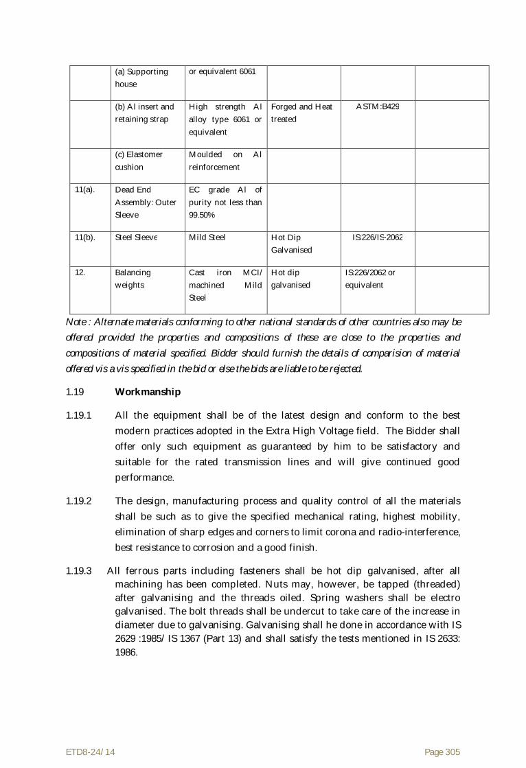
ETD8-24/14 Page 305
(a) Supporting house
or equivalent 6061
(b) Al insert and retaining strap
High strength Al alloy type 6061 or equivalent
Forged and Heat treated
ASTM:B429
(c) Elastomer cushion
Moulded on Al reinforcement
11(a). Dead End Assembly: Outer Sleeve
EC grade Al of purity not less than 99.50%
11(b). Steel Sleeve Mild Steel Hot Dip Galvanised
IS:226/IS-2062
12. Balancing weights
Cast iron MCI/ machined Mild Steel
Hot dip galvanised
IS:226/2062 or equivalent
Note : Alternate materials conforming to other national standards of other countries also may be offered provided the properties and compositions of these are close to the properties and compositions of material specified. Bidder should furnish the details of comparision of material offered vis a vis specified in the bid or else the bids are liable to be rejected.
1.19 Workmanship
1.19.1 All the equipment shall be of the latest design and conform to the best modern practices adopted in the Extra High Voltage field. The Bidder shall offer only such equipment as guaranteed by him to be satisfactory and suitable for the rated transmission lines and will give continued good performance.
1.19.2 The design, manufacturing process and quality control of all the materials shall be such as to give the specified mechanical rating, highest mobility, elimination of sharp edges and corners to limit corona and radio-interference, best resistance to corrosion and a good finish.
1.19.3 All ferrous parts including fasteners shall be hot dip galvanised, after all machining has been completed. Nuts may, however, be tapped (threaded) after galvanising and the threads oiled. Spring washers shall be electro galvanised. The bolt threads shall be undercut to take care of the increase in diameter due to galvanising. Galvanising shall he done in accordance with IS 2629 :1985/ IS 1367 (Part 13) and shall satisfy the tests mentioned in IS 2633: 1986.

ETD8-24/14 Page 306
1.19.4 Before ball fittings are galvanised. all die flashing on the shank and on the bearing surface of the ball shall be carefully removed without reducing the dimensions below the design requirements.
1.19.5 The zinc coating shall be perfectly adherent, of uniform thickness, smooth, reasonably bright, continuous and free from imperfections such as flux, ash rust, stains, bulky white deposits and blisters. The zinc used for galvanising shall be Zinc of any grade in IS 209:1992 ingot (fourth revision) or IS 13229:1991.
1.19.6 Pin balls shall be checked with the applicable “GO” gauges in at least two directions. one of which shall be across the line of die flashing, and the other
90o to this line. "NO GO" gauges shall not pass in any direction.
1.19.7 Socket ends, before galvanising, shall be of uniform contour. The bearing surface of socket ends shall be uniform about the entire circumference without depressions of high spots. The internal contours of socket ends shall be concentric with the axis of the fittings as per IS:2486/IEC : 120.
The axis of the bearing surfaces of socket ends shall be coaxial with the axis of the fittings. There shall be no noticeable tilting of the bearing surfaces with the axis of the fittings.
1.19.8 In case of casting, the same shall be free from all internal defects like shrinkage, inclusion, blow holes, cracks etc. Pressure die casting shall not be used for casting of components with thickness more than 5 mm.
1.19.9 All current carrying parts shall be so designed and manufactured that contact resistance is reduced to minimum.
1.19.10 No equipment shall have sharp ends or edges, abrasions or projections and cause any damage to the conductor in any way during erection or during continuous operation which would produce high electrical and mechanical stresses in normal working. The design of adjacent metal parts and mating surfaces shall be such as to prevent corrosion of the contact surface and to maintain good electrical contact under service conditions.
1.19.11 All the holes shall be cylindrical, clean cut and perpendicular to the plane of the material. The periphery of the holes shall be free from burrs.
1.19.12 All fasteners shall have suitable corona free locking arrangement to guard against vibration loosening.
1.19.13 Welding of aluminium shall be by inert gas shielded tungsten arc or inert gas shielded metal arc process. Welds shall be clean, sound, smooth, uniform

ETD8-24/14 Page 307
without overlaps, properly fused and completely sealed. There shall be no cracks, voids incomplete penetration, incomplete fusion, under-cutting or inclusions. Porosity shall be minimised so that mechanical properties of the aluminium alloys are not affected. All welds shall be properly finished as per good engineering practices.
1.20 Bid Drawings
1.20.1 The Bidder shall furnish full description and illustrations of materials offered.
1.20.2 Fully dimensioned drawings of the complete insulator string hard wares and their component parts showing clearly the following arrangements shall be furnished along with the bid. Weight, material and fabrication details of all the components should be included in the drawings.
(i) Attachment of the hanger or strain plate.
(ii) Suspension or dead end assembly.
(iii) Arcing horn attachment to the string as specified in clause 1.8 of this technical Specification.
(iv) Yoke plates
(v) Hardware fittings of ball and socket type for inter connecting units to the top and bottom Yoke plates.
(vi) Corona control rings/grading ring attachment to conductor and other small accessories.
(vii) Links with suitable fittings.
(viii) Details of balancing weights and arrangements for their attachment in the single suspension pilot insulator string.
1.20.3 All drawings shall be identified by a drawing number and contract number. All drawings shall be neatly arranged. All drafting & lettering shall be legible. The minimum size of lettering shall be 3 mm. All dimensions & dimensional tolerances shall be mentioned in mm.
The drawings shall include :
(i) Dimensions and dimensional tolerance.
(ii) Material, fabrication details including any weld details & any specified finishes & coatings. Regarding material designation & reference of standards are to be indicated.
(iii) Catalogue No.

ETD8-24/14 Page 308
(iv) Marking
(v) Weight of assembly
(vi) Installation instructions
(vii) Design installation torque for the bolt or cap screw.
(viii) Withstand torque that may be applied to the bolt or cap screw without failure of component parts.
(ix) The compression die number with recommended compression pressure.
(x) All other relevant terminal details.
1.20.4 After placement of award, the Contractor shall submit fully dimensioned drawing including all the components in four (4) copies to the Owner for approval. After getting approval from the Owner and successful completion of all the type tests, the Contractor shall submit thirty (30) more copies of the same drawings to the Owner for further distribution and field use at Owner's end.
2.0 Accessories for ACSR Moose Conductor
2.1 General
2.1.1 This portion (under clause 2.0) details the technical particulars of the accessories for Conductor.
2.1.2 2.5% extra fasteners and retaining rods shall be provided.
2.2 Mid Span Compression Joint
2.2.1 Mid Span Compression Joint shall be used for joining two lengths of conductor. The joint shall have a resistively less than 75% of the resistivity of equivalent length of conductor. The joint shall not permit slipping off, damage to or failure of the complete conductor or any part there of at a load less than 95% of the ultimate tensile strength of the conductor.
2.2.2 The joint shall be made of steel and aluminium sleeves for jointing the steel core and aluminium wires respectively. The steel sleeve should not crack or fail during compression. The steel sleeve shall be hot dip galvanised. The aluminium sleeve shall have aluminium of purity not less than 99.5%. The dimensions and dimensional tolerances of mid span compression joint shall be as per Standard Technical Particulars.

ETD8-24/14 Page 309
2.3 T-Connector
T-Connector of compression type shall be used for jumper connection at transposition tower . It shall be manufactured out of 99.5% pure aluminium and shall be strong enough to withstand normal working loads. The T-connector shall have a resistivity across jumper less than 75% resistivity of equivalent length of conductor. The T-connector shall not permit slipping off, damage to or failure of complete conductor . The welded portions shall be designed for 30 kN axial tensile load. Leg sleeve of T-connector should be kept at an angle of 15 deg. from vertical and horizontal plane of the conductor in order to minimise jumper pull at the welded portion. The dimensions and dimensional tolerances of T-connector shall be as per Standard Technical Particulars.
2.4 Repair Sleeve
Repair Sleeve of compression type shall be used to repair conductor with not more than two strands broken in the outer layer. The sleeve shall be manufactured from 99.5% pure aluminium and shall have a smooth surface. The repair sleeve shall comprise of two pieces with a provision of seat for sliding of the keeper piece. The edges of the seat as well as the keeper piece shall be so rounded that the conductor strands are not damaged during installation. The dimensions and dimensional tolerances of repair sleeve shall be as per Standard Technical Particulars.
2.5 Spacer Damper
2.5.1 Suitable spacer dampers for four bundle ACSR MOOSE conductor for 400 kV (Quad) line shall be offered. The spacer damper covered by this specification shall be designed to maintain the bundle spacing of 457 mm under all normal operating conditions and to effectively control Aeolian vibrations as well as sub span oscillation and to restore conductor spacing after release of any external extraordinary load. The nominal sub conductor spacing shall be maintained within ±5 mm.
2.5.2 The spacer damper shall restore the normal sub-conductor spacing due to displacement by wind, electromagnetic and electrostatic forces including the specified short circuit level without permanent deformation or damage either to bundle conductors or to spacer damper itself.
2.5.3 The design offered shall be presented as a system consisting of spacer dampers and their staggering scheme for spans ranging from 100 m to 1100

ETD8-24/14 Page 310
m. A vibration performance test shall be carried out on an experimental test line. The systems tested should be those specified by the Supplier for the 400 kV line conditions. Only systems satisfying the performance criteria under Annexure-A shall be submitted by Bidder along with bid.
The test line selected for the performance evaluation shall have been designed for that purpose, be adequately exposed to wind and properly instrumented.
Sl. Description Technical Particulars
1. Configuration Double circuit for 400 kV line:
Four ACSR MOOSE Quad conductor bundle per phase and all three phases in vertical configuration. Refer section–I for mechanical properties of conductor
2. Span length in metres
i) Ruling design span
ii) Maximum span
iii) Minimum Span
400 metres
1100 metres
100 metres
3. Tensile load in each sub-conductor
As per sag tension calculations.
4. Armour rods used Yes
5. Maximum permissible dynamic strains
± 150 micro strains
2.6.4 Under the operating conditions specified, the spacer damper system shall adequately control Aeolian vibrations throughout the life of the transmission line with wind velocity ranging from 0 to 30 km per hour in order to prevent damage to conductor at suspension clamps, dead end clamps and spacer damper clamps.
2.6.5 The spacer damper system shall also control the sub-span oscillations in order to prevent conductor damage due to chaffing and severe bending stresses at the

ETD8-24/14 Page 311
spacer damper clamps as well as suspension and dead end clamps and to avoid wear to spacer damper components.
2.6.6 The spacer damper shall consist of a rigid central body called the frame linked to the conductor by four articulated arms terminated by suitable clamping system. The articulation shall be designed to provide elastic and damping forces under angular movement of the arms. The dynamic characteristics of the articulations shall be maintained for the whole life of the transmission line.
2.6.7 The clamping system shall be designed to provide firm but gentle and permanent grip while protecting the conductor against local static or dynamic stresses expected during normal operating conditions. The clamping system shall be designed to compensate for any reduction of conductor diameter due to creep.
2.6.8 Bolted type clamps shall allow installation without removal of the bolts or the clamps from clamp body. Locking mechanism shall be suitable to prevent bolt loosening. Clamp locking devices with small loose components shall not be accepted. Nut cracker, hinged open or boltless type clamps are acceptable provided adequate grip can be maintained on the conductor.
2.6.9 Bolts and nuts shall be of mild steel, stainless steel, or high strength steel in accordance with the design of the spacer damper.
2.6.10 Where elastomer surfaced clamps are used, the elastomer elements shall be firmly fixed to the clamp. The insert should be forged from aluminium alloy of type 6061 or equivalent aluminium alloy having minimum tensile strength of 25 kg/mm2. The insert shall be moulded on the insert surface. The insert shall be duly heat treated and aged to retain its consistent characteristics during service. The grain flow of the forged insert shall be in the direction of the maximum tension and compression loads experienced.
2.6.11 If clamps involving preformed rods are used, these rods shall be designed for specific conductor size. They shall be made of high strength aluminium alloy of type 6061 or equivalent aluminium alloy having a minimum tensile strength of 35 kg/mm3. The rods shall be ball ended. The rods shall be heat treated and aged to achieve specified mechanical properties and to retain the same during service. The length of the rods shall be such that the ends fall inside the imaginary square whose sides are vertical and horizontal outer tangents to the conductor sections.
2.6.12 The spacer damper body shall be cast/ forged from suitable high strength corrosion resistant aluminium alloy. The aluminium alloy shall be chosen in relation with the process used.
2.6.13 The rubber components involved in the design such as damping elements shall be made with rubber compound selected specifically for that particular application. The Bidder shall submit a complete list of physical and mechanical properties of the elastomer used. This list shall make reference to all applicable ASTM standards.
2.6.14 The rubber components used shall have good resistance to the effects of temperature up to 95°C and to ultraviolet radiation, ozone and other atmospheric contaminants. The rubber shall have good wear and fatigue resistance and shall be electrically semi-conductive.

ETD8-24/14 Page 312
2.6.15 The spacer damper involving ferrous material shall not have magnetic power loss more than that stipulated in the Standard Technical Particulars at 600 A, 50 Hz alternating current per sub-conductor.
2.6.16 The spacer damper assembly shall have electrical continuity. The electrical resistance between the sub-conductors across the assembly in case of spacer damper involving elastomer surfaced clamps shall be suitably selected by the manufacturer to ensure satisfactory electrical performance and avoid deterioration of elastomer under service conditions.
2.6.17 The spacer damper assembly shall have complete ease of installation and shall be capable of removal/reinstallation without any damage.
2.6.18 The spacer damper assembly shall be capable of being installed and removed from the energized line by means of hot line techniques. The Bidder shall supply with the bid the complete description of the installation, removal and reinstallation procedure.
2.6.19 The Bidder shall recommend the staggering scheme for installation of spacer dampers on the line which shall ensure most satisfactory fatigue performance of the line as specified. The scheme shall indicate the number of spacer dampers per phase per span and the sub span lengths to be maintained between spacer dampers while installing on the four bundle conductors.
2.6.20 The staggering scheme shall be provided for spans ranging from 100 m to 1100 m. The number of spacer dampers for a nominal ruling span of 400 m shall not be less than six.
2.6.21 No sub span shall be greater than 70 m and no end sub span shall be longer than 40 m.
2.6.22 The staggering scheme shall be such that the spacer dampers be unequally distributed along the span to achieve sufficient detuning of adjacent subs pans for oscillations of sub span mode and to ensure bundle stability for wind speeds up to 60 km/hr.
2.6.23 The Bidder shall furnish all the relevant technical documents in supports of the staggering scheme recommended for the spacer damper.
2.7 Rigid Spacer for Jumper for Quad Conductor
2.7.1 Jumpers at tension points shall be fitted with spacers so as to limit the length of free conductor to 3.65 m and to maintain the sub conductor spacing of 457 mm. Bidder shall quote for rigid spacer for jumper. It shall meet all the requirements of spacer used in line except for its vibration performance. Spacers requiring retaining rods shall not be quoted for jumpers.
2.7.2 The spacer offered by the Bidder shall satisfy the following requirements.
2.7.2.1 Spacer shall restore normal spacing of the sub conductors after displacement by wind, electromagnetic and the electrostatic forces under all operating conditions including the specified short circuit level without permanent deformation damage either to conductor or to the assembly itself. They shall have uniform grip on the conductor

ETD8-24/14 Page 313
2.7.2.2 For spacer requiring retaining rods, the retaining rods shall be designed for the specified conductor size. The preformed rods shall be made of high strength, special aluminium alloy of type 6061/65032 and shall have minimum tensile strength of 35 kg/sq.mm. The ends of retaining rods should be ball ended. The rods shall be heat-treated to achieve specified mechanical properties and give proper resilience and retain the same during service.
2.7.2.3 Four number of rods shall be applied on each clamps to hold the clamp in position. The minimum diameter of the rods shall be 7.87 + 0.1 mm and the length of the rods shall not be less than 1100 mm.
2.7.2.4 Where elastomer surfaced clamp grooves are used, the elastomer shall be firmly fixed to the clamp. The insert should be forged from aluminium alloy of type 6061/65032. The insert shall be duly heat treated and aged to retain its consistent characteristics during service.
2.7.2.5 Any nut used shall be locked in an approved manner to prevent vibration loosening. The ends of bolts and nuts shall be properly rounded for specified corona performance or suitably shielded.
2.7.2.6 Clamp with cap shall be designed to prevent its cap from slipping out of position when being tightened.
2.7.2.7 The clam grooves shall be in uniform contact with the conductor over the entire surface, except for rounded edges. The groove of the clamp body and clamp cap shall be smooth and free of projections, grit or other material. which cause damage to the conductor when the clamp is installed.
2.7.2.8 For the spacer involving bolted clamps, the manufacturer must indicate the clamp bolt tightening torque to ensure that the slip strength of the clamp is maintained between 2.5 kN and 5 kN. The clamp when installed on the conductor shall not cause excessive stress concentration on the conductor leading to permanent deformation of the conductor strands and premature fatigue failure in operation.
2.7.2.9 Universal type bolted clamps, covering a range of conductor sizes, will not be permitted.
2.7.2.10 No rubbing, other than that of the conductor clamp hinges or clamp swing bolts, shall take place between any parts of the spacer. Joint incorporating a flexible medium shall be such that there is no relative slip between them.
2.7.2.11 The spacer shall be suitably designed to avoid distortion or damage to the conductor or to themselves during service.
2.7.2.12 Rigid spacers shall be acceptable only for jumpers.

ETD8-24/14 Page 314
2.7.2.13 The spacer shall not damage or chafe the conductor in any way which might affect its mechanical and fatigue strength or corona performance.
2.7.2.14 The clamping system shall be designed to compensate for any reduction in diameter of conductor due to creep.
2.7.2.15 The spacer assembly shall not have any projections, cuts, abrasions etc. or chattering parts which might cause corona or RIV.
2.72.16 The spacer tube shall be made of aluminium alloy of type 6061/65032. If fasteners of ferrous material are used, they shall conform to and be galvanised conforming to relevant Indian Standards. The spacer involving ferrous fasteners shall not have magnetic power loss more than one watt at 600 Amps 50 Hz alternating current per sub conductor.
2.7.2.17 Elastomer, if used, shall be resistant to the effects of temperature up to 95 deg.C, ultraviolet radiation and other atmospheric contaminants likely to be encountered in service. It shall have good fatigue characteristics. The physical properties of the elastomer shall be of approved standard.
2.7.2.18 The spacer assembly shall have electrical continuity. The electrical resistance between the sub-conductor across the assembly in case of spacer having elastomer clamp grooves shall be suitably selected by the manufacturers to ensure satisfactory electrical performance and to avoid deterioration of elastomer under all service conditions.
2.7.2.19 The spacer assembly shall have complete ease of installation and shall be capable of removal/reinstallation without any damage.
2.7.2.20 The spacer assembly shall be capable of being installed and removed from the energised line by means of hot line technique.
2.8 Material and Workmanship
2.8.1 All the equipment shall be of the latest proven design and conform to the best modern practice adopted in the extra high voltage field. The Bidder shall offer only such equipment as guaranteed by him to be satisfactory and suitable for 400 kV transmission line application with bundle conductors and will give continued good performance.
2.8.2 The design, manufacturing process and quality control of all the materials shall be such as to achieve requisite factor of safety for maximum working load, highest mobility, elimination of sharp edges and corners, best resistance to corrosion and a good finish.

ETD8-24/14 Page 315
2.8.3 All ferrous parts shall be hot dip galvanised, after all machining has been completed. Nuts may, however, be tapped (threaded) after galvanising and the threads oiled. Spring washers shall be electro galvanised as per grade 4 of IS-1573-1970. The bolt threads shall be undercut to take care of increase in diameter due to galvanising. Galvanising shall be done in accordance with IS:2629/IS-1367 (Part-13) and satisfy the tests mentioned in IS-2633. Fasteners shall withstand four dips while spring washers shall withstand three dips. Other galvanised materials shall have a minimum overall coating of Zinc equivalent to 600 gm/sq.m and shall be guaranteed to withstand at least six dips each lasting one minute under the standard Preece test for galvanising unless otherwise specified.
2.8.4 The zinc coating shall be perfectly adherent, of uniform thickness, smooth, reasonably bright, continuous and free from imperfections such as flux, ash, rust stains, bulky white deposits and blisters. The zinc used for galvanising shall be of grade Zn.99.95 as per IS:209.
2.8.5 In case of castings, the same shall be free from all internal defects like shrinkage, inclusion, blow holes. cracks etc.
2.8.6 All current carrying parts shall be so designed and manufactured that contact resistance is reduced to minimum and localised heating phenomenon is averted.
2.8.7 No equipment shall have sharp ends or edges, abrasions or projections and shall not cause any damage to the conductor in any way during erection or during continuous operation which would produce high electrical and mechanical stresses in normal working. The design of adjacent metal parts and mating surfaces shall be such as to prevent corrosion of the contact surface and to maintain good electrical contact under all service conditions.
2.8.8 Particular care shall be taken during manufacture and subsequent handling to ensure smooth surface free from abrasion or cuts.
2.8.9 The fasteners shall conform to the requirements of IS:6639. All fasteners and clamps shall have corona free locking arrangement to guard against vibration loosening.
2.9 Compression Markings
Die compression areas shall be clearly marked on each equipment designed for continuous die compressions and shall bear the words ‘COMPRESS FIRST’ ‘suitably inscribed on each equipment where the compression begins. If the equipment is designed for intermittent die compressions, it shall bear the identification marks ‘COMPRESSION ZONE’ and ‘NON-COMPRESSION ZONE’ distinctly with arrow marks showing the direction of compression and

ETD8-24/14 Page 316
knurling marks showing the end of the zones. The letters, number and other markings on finished equipment shall be distinct and legible.
2.10 Bid Drawings
2.10.1 The Bidder shall furnish detailed dimensioned drawings of the equipments and all component parts. Each drawing shall be identified by a drawing number and Contract number. All drawings shall be neatly arranged. All drafting and lettering shall be legible. The minimum size of lettering shall be 3 mm. All dimensions and dimensional tolerances shall be mentioned in mm.
2.10.2 The drawings shall include
(i) Dimensions and dimensional tolerances
(ii) Material. fabrication details including any weld details and any specified finishes and coatings. Regarding material, designations and reference of standards are to be indicated.
(iii) Catalogue No.
(iv) Marking
(v) Weight of assembly
(vi) Installation instructions
(vii) Design installation torque for the bolt or cap screw
viii) Withstand torque that may be applied to the bolt or cap screw without failure of component parts
(ix) The compression die number with recommended compression pressure.
(x) All other relevant technical details
2.10.3 Placement charts for spacer and damper
2.10.4 The above drawings shall be submitted with all the details as stated above along with the bid document. After the placement of award. the Contractor shall again submit the drawings in four copies to the Purchaser for approval. After Purchaser’s approval and successful completion of all type tests, 10 (ten) more sets of drawings shall be submitted to Purchaser for further distribution and field use at Purchaser’s end.

ETD8-24/14 Page 317
3.0 G.S. Earth wire Accessories
3.1 General
3.1.1 This portion Specify the details of the technical particulars of the accessories for Galvanised Steel Earth wire.
3.1.2 2.5% extra fasteners shall be supplied.
3.2 Mid Span Compression Joint
Mid Span Compression Joint shall be used for joining two lengths of earth wire. The joint shall be made of mild steel with aluminium encasing. The steel sleeve should not crack or fail during compression. The Brinnel Hardness of steel should not exceed the value as stipulated in the Standard Technical Particulars. The steel sleeve shall be hot dip galvanised. The aluminium sleeve shall have aluminium of purity not less than that stipulated in the Standard Technical Particulars. Filler aluminium sleeve shall also be provided at the both ends. The joints shall not permit slipping off, damage to or failure of the complete earth wire or any part thereof at a load not less than 95% of the ultimate tensile strength of the earth wire. The joint shall have resistivity less than 75% of resistivity of equivalent length of earth wire. The dimensions and the dimensional tolerances of the joint shall be as stipulated in the Standard Technical Particulars.
3.3 Vibration Damper
3.3.1 Vibration dampers of 4R-Stockbridge type with four (4) different frequencies spread within the specified aeolian frequency band-width corresponding to wind speed of 5m/s to 7 m/s shall be used for suspension and tension points on each earth wire in each span to damp out aeolian vibrations as mentioned herein after.
3.3.2 Alternate damping systems or “Dogbone” dampers offering equivalent or better performance also shall be acceptable provided the manufacturer meets the qualifying requirements stipulated in the Specifications. Relevant technical documents to establish the technical suitability of alternate systems shall be furnished by the Bidder along with the bid.
3.3.3 One damper minimum on each side per earth wire at suspension points and two dampers on each side per earth wire at tension points shall be used for ruling design span of 400 meters for 400 kV line.
3.3.4 The Bidder may offer damping system involving more number of dampers per ruling design span than the specified. However suitable price

ETD8-24/14 Page 318
compensation shall be considered for evaluation. For the purpose of price compensation 80% of towers as suspension locations and 20% of the towers as tension locations and all the spans assumed to be ruling design spans.
3.3.5 The clamp of the vibration damper shall be made of aluminium alloy. It shall be capable of supporting the damper during installation and prevent damage or chaffing of the earth wire during erection or continued operation. The clamp shall have smooth and permanent grip to keep the damper in position on the earth wire without damaging the strands or causing premature fatigue failure of the earth wire under the clamp. The clamp groove shall be in uniform contact with the earth wire over the entire clamping surface except for the rounded edges. The groove of the clamp body and clamp cap shall be smooth, free from projections, grit or materials which could cause damage to the earth wire when the clamp is installed. Clamping bolts shall be provided with self locking nuts designed to prevent corrosion of the threads or loosening during service.
3.3.6 The messenger cable shall be made of high strength galvanised steel/stainless steel with a minimum strength of 135 Kg/sq.mm. It shall be of preformed and post formed quality in order to prevent subsequent droop of weights and to maintain consistent flexural stiffness of the cable in service. The number of standards in the messenger cable shall be 19. The messenger cable ends shall be suitably and effectively sealed to prevent corrosion.
3.3.7 The damper mass shall be made of hot dip galvanised mild steel/cast iron or a permanent mould cast zinc alloy. All castings shall be free from defects such as cracks, shrinkages, inclusions and blow holes etc. The inside and outside surfaces of the damper masses shall be smooth.
3.3.8 The vibration analysis of the system, with and without damper, dynamic characteristic of the damper as detailed under Annexure-A, shall have to be submitted by the Bidder along with his bid. The technical particulars for vibration analysis and damping design of the system are as follows:-
Sl. Description Technical particulars
1. Configuration Two continuously steel earthwire 10.98 mm diameter in horizontal configuration. Refer to Section-I for mechanical properties of the earthwire.

ETD8-24/14 Page 319
2. Span length in meters
i) Ruling design span 400 meters
ii) Maximum span 1100 meters
iii) Minimum span 100 meters
3. Tensile load in Conductor at temperature of 0 deg. C and still air
As per sag tension calculations.
4. Maximum permissible dynamic strain
+/- 150 micro strains
3.3.9 The damper placement chart for spans ranging from 100 m to 1100 m shall be submitted by the Bidder. All the placement charts should be duly supported by relevant technical documents.
3.3.10 The damper placement charts shall include the following :
(1) Location of the dampers for various combinations of spans and line tensions clearly indicating number of dampers to be installed per earth wire per span.
(2) Placement distances clearly identifying the extremities between which the distances are to be measured.
(3) Placement recommendation depending upon type of suspension clamps (viz, free center type/trunion type etc.)
(4) The influence of mid span compression joints in the placement of dampers.
3.4 Flexible Copper Bond
The flexible copper bond shall be circular in cross-section of minimum 34 sq.mm equivalent copper area and not less than 500 mm in length. It shall consist of 259 wires of 0.417 mm dia. tinned copper conductor. It shall be laid up as 7 stranded ropes, each of 37 bunched wires. The tinning shall be as per relevant Indian Standard. Two tinned copper connecting lugs shall be press jointed to either ends of the flexible copper cable. One lug shall be suitable for 12 mm, dia. bolt and the other for 16 mm dia bolt. The complete assembly shall also include one 16 mm dia., 40 mm long HRH MS Bolt hot dip galvanised with nut and lock washer.

ETD8-24/14 Page 320
3.5 Suspension Clamp
3.5.1 Standard anchor shackle/twisted shackle for earth wire suspension clamp shall be supplied for attaching to the hanger plate of tower.
3.5.2 At all suspension towers, suitable suspension clamps shall be used to support the required earth wire. The clamps shall be of either free center type or trunion type and shall provide adequate area of support to the earth wire. The groove of the clamp shall be smooth, finished in an uniform circular or oval shape and shall slope downwards in a smooth curve to avoid edge support and hence to reduce the intensity of bending moment on earth wire.
3.5.3 There shall be no sharp point in the clamps coming in contact with earth wire. There shall not be any displacement in the configuration of the earth wire strands nor shall the strands be unduly stressed in final assembly during working conditions.
3.5.4 The clamping piece and the clamp body shall be clamped by at least two U-bolts of size not less than 10 mm diameter having one nut and one 3 mm thick lock nut with washer on each of its limbs. Suspension clamps shall be provided with inverted type U-bolts. One limb of the U-bolt shall be long enough to accommodate the lug of the flexible copper bond.
3.5.5 The Contractor shall supply all the components of the suspension assembly including shackles, bolts, nuts, washers, split pin etc. The total drop of the suspension assembly from the center point of the attachment to the center point of the earth wire shall not exceed 150 mm. The design of the assembly shall be such that the direction of run of the earth wire shall be same as that of the conductor.
3.5.6 The complete assembly shall be guaranteed for slip strength of not less than 12 KN and not more than 17 kN. The breaking strength of the assembly shall not be less than 25 kN.
3.6 Tension Clamp
3.6.1 At all tension towers suitable compression type tension clamps shall be used to hold the required galvanised steel earth wire. Anchor shackle shall be supplied which shall be suitable for attaching the tension clamp to strain plates.
3.6.2 The clamps shall have adequate area of bearing surface to ensure positive electrical and mechanical contact and shall not permit any slip to the earth wire under working tension and vibration conditions. The angle of jumper terminal to be mounted should be 30 deg. with respect to the vertical line.

ETD8-24/14 Page 321
3.6.3 The clamps shall be made of mild steel with aluminium encasing. The steel should not crack or fail during compression. The Brinnel hardness of steel sleeve shall not exceed 200. The steel sleeve shall be hot dip galvanised. The aluminium encasing shall have aluminium of purity not less than 99.5%. Filler aluminium sleeve shall also be provided at the end.
3.6.4 The complete assembly shall be so designed as to avoid undue bending in any part of the clamp and shall not produce any hindrance to the movements of the clamps in horizontal or vertical directions.
3.6.5 The slip strength of the assembly shall not be less than 95% of the ultimate strength of the earth wire.
3.6.6 The clamps shall be complete with all the components including anchor shackle, bolts, nuts, washers, split pin, jumper arrangement etc.
3.7 Material and Workmanship
Same as Clause 2.9 of this section
3.8 Compression Marking
Same as Clause 2.10 of this section
3.9 Bid Drawings
Same as Clause 2.11 of this section 4.0 Standard technical particulars
4.1 The Standard technical particulars to adhered by the contractor / manufacturer are furnished below:

ETD8-24/14 Page 322
Standardised Technical Particulars of Hardware Fittings and Accessories of Quad ACSR MOOSE conductor for 400 kV Transmission Line
1. SUSPENSION HARDWARE FITTINGS FOR QUAD ACSR ‘MOOSE’ CONDUCTOR
Sl.
Description Unit Particulars / Value
Double ‘I’ Single ‘I’
Pilot
AGS clamp
Free centre clamp
Envelope clamp
1. Maximum magnetic power loss of suspension assembly at sub conductor current of 600 amperes, 50Hz AC
Watt 4 8
2. Slipping strength of suspension assembly(clamp torque Vs slip curve shall be enclosed)
kN 20-29
3. Particulars of standard/AGS Standard / AGS preformed armour rod set for suspension assembly
a) No. of rods per set No. 12 NA
b) Direction of lay Right Hand NA
c) Overall length after fitting on conductor mm 2235 2540 NA
d) Diameter of each rod mm 9.27 NA
e) Tolerance in NA
i) Diameter of each rod ±mm 0.10 NA
ii) Length of each rod ±mm 25 NA
iii) Difference of length between the longest and shortest rod in a set
±mm 13 NA

ETD8-24/14 Page 323
g) Type of Aluminium alloy used for manufacture of PA rod set
6061/ 65032 NA
h) UTS of each rod (Min) Kg/mm2 35 NA
4. Particulars of Elastomer (For AGS Clamp only)
a) Type of elastomer Chloroprene /
Neoprene
NA NA
b) Shore hardness of elastomer 65 - 80 NA NA
c) Temperature range for which elastomer designed
°C Upto 95°C NA NA
d) Moulded on insert Yes NA NA
5. Mechanical Strength of Suspension fitting (excluding suspension clamp)
KN 240 120
6. Mechanical Strength of suspension clamp. 70 70 70
7. Purity of Zinc used for galvanizing % As per IS:209 / IS 13229
8. Min. No. of dips in standard preece test the ferrous parts can withstand
No a) Fasteners : 4 dips of 1 min
b) Spring washers : 3 dips of 1 min
c) All others : 6 dips of 1 min
2. TENSION HARDWARE FITTINGS QUAD ACSR MOOSE CONDUCTOR
Sl. Description Unit Particulars / Value
Single Tension
Quad Tension
1. Mechanical Strength of Tension fittings (excluding dead end clamp)
kN 120 640
2. Type of Dead End assembly Compression

ETD8-24/14 Page 324
3. Compression Pressure MT 100
4. Maximum electrical resistance of dead end assembly as a percentage of equivalent length of Conductor
% 75
5. Slip strength of dead end assembly kN 153.2
6. Purity of Zinc used for galvanizing % As per IS:209 / IS 13229
7. Min. No. of dips in standard preece test the ferrous parts can withstand.
Nos a) Fasteners : 4 dips of 1 min
b) Spring washers : 3 dips of 1 min
c) All others : 6 dips of 1 min
MID SPAN COMPRESSION JOINT FOR ACSR MOOSE CONDUCTOR
Sl. Description Unit Particulars/ Value
Aluminium Sleeve
Steel Sleeve
1. Material of Joint Aluminium of purity 99.5%
Mild Steel(Fe-410, IS:2062)
2. Range of Hardness of the steel sleeve
(Brinnel hardness)
BHN From 100 to 200
3. Weight of Zinc coating for steel sleeve gm/m2 610
4. Dimension of sleeve Before compression
Aluminum sleeve
Steel sleeve
i) Inside diameter mm 34.00 ± 0.5 11.10 ± 0.2
ii) Outside diameter mm 54.00 ± 1.0 21.00 ± 0.5
iii) Length mm 735 ± 5 250 ± 5

ETD8-24/14 Page 325
5. Dimensions of Sleeve after compression
Aluminum sleeve
Steel sleeve
i) Outside dimension(Corner to corner) mm 53.00 ± 0.5 20.20 ± 0.5
ii) Outside dimension ( face to face) mm 46.00 ± 0.5 17.50 ± 0.5
iii) Length mm 785 (approx) 286 (approx)
6. Slip strength KN 153.2
7. Maximum resistance of the compressed unit expressed, as percentage of the resistance of equivalent length of bare conductor.
% 75
8. Minimum corona Extinction voltage kV (rms) under dry condition
kV 320
9. Maximum Radio Interference Voltage at 1 MHz for phase to earth voltage of 305 kV (rms) under dry condition
Micro Volts
1000
REPAIR SLEEVE FOR ACSR MOOSE CONDUCTOR
Sl. Description Unit Particulars/ Value
1. Material Aluminium of minimum purity 99.5%
2. Dimension of Aluminum sleeve Before compression
i) Inside diameter mm 34.00 ± 0.5
ii) Outside diameter mm 54.00 ± 1.0
iii) Length mm 300.00 ± 5.0
3. Dimensions of Aluminum Sleeve after compression
i) Outside dimension(Corner to corner) mm 53.00 ± 0.5
ii) Outside dimension (face to face) mm 46.00 ± 0.5

ETD8-24/14 Page 326
iii) Length mm 330.00(Approx.)
4. Minimum corona Extinction voltage kV (rms) under dry condition
kV 320
5. Maximum Radio Interference Voltage at 1 MHz for phase to earth voltage of 305 kV (rms) under dry condition
Micro Volts
1000
QUAD SPACER DAMPER FOR QUAD ACSR MOOSE CONDUCTOR
Sl. Description Unit Particulars / Value
1. Type of Clamps Bolted / Nut cracker / Hinged open / Boltless / Preformed rods.
2. Type of Damping element Spring / Elastomer / EPDM
3. Material of
(a) Clamp Al Alloy IS:4600 or Equivalent
( b) Body Galvanised Steel / Al Alloy 4600 or Equivalent
4. Elastomer (if used)
(a) Shore hardness 50 - 80
(b) Temp. range for which designed
°C Upto 95°C
5. Minimum ultimate tensile strength of spacer
(a) Compressive load kN 14
(b) Tensile load kN 7.0

ETD8-24/14 Page 327
6. Slipping strength of spacer clamp
(a) Before vibration test kN
Clamp type
Longitudnal Load (kN)
Maxm Slip permitted (mm)
Metal – Metal Bolted
6.5 1
Rubber loaded 2.5 2.5
Preformed rods
2.5 12
(b) After vibration test kN 80% of the above values
7. Maximum magnetic power loss of at sub conductor current of 600 amperes, 50Hz AC
Watt Below 1 watt.
8. Minimum corona Extinction voltage kV (rms) under dry condition
kV 320
9. Radio Interference Voltage at 1 MHz for phase to earth voltage of 305 kV (rms) Microvolts under dry condition
µV Below 1000
QUAD RIGID SPACER FOR QUAD ACSR MOOSE CONDUCTOR
Sl. Description Unit Particulars / Value
1. Material of
(a) Clamp Al Alloy IS:4600 or Equivalent
( b) Body Galvanised Steel / Al Alloy 4600 or Equivalent
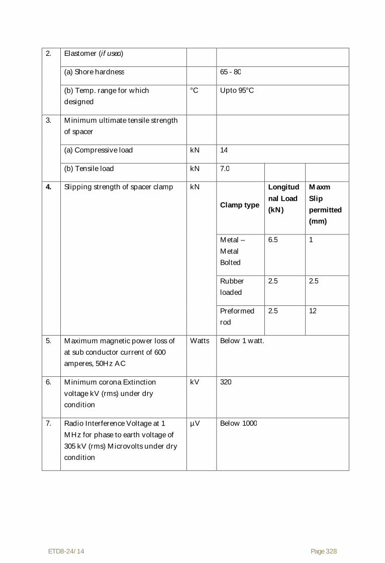
ETD8-24/14 Page 328
2. Elastomer (if used)
(a) Shore hardness 65 - 80
(b) Temp. range for which designed
°C Upto 95°C
3. Minimum ultimate tensile strength of spacer
(a) Compressive load kN 14
(b) Tensile load kN 7.0
4. Slipping strength of spacer clamp
kN
Clamp type
Longitudnal Load (kN)
Maxm Slip permitted (mm)
Metal – Metal Bolted
6.5 1
Rubber loaded
2.5 2.5
Preformed rod
2.5 12
5. Maximum magnetic power loss of at sub conductor current of 600 amperes, 50Hz AC
Watts Below 1 watt.
6. Minimum corona Extinction voltage kV (rms) under dry condition
kV 320
7. Radio Interference Voltage at 1 MHz for phase to earth voltage of 305 kV (rms) Microvolts under dry condition
µV Below 1000

ETD8-24/14 Page 329
T-CONNECTOR FOR ACSR MOOSE CONDUCTOR
Sl. Description Unit Particulars/ Value
1. Material Aluminium of purity 99.5%
2. Dimension of Aluminum sleeve Before compression
i) Inside diameter mm 34.00 ± 0.5
ii) Outside diameter mm 54.00 ± 1.0
iii) Length mm 400.00 ± 5.0
3. Dimensions of Aluminum Sleeve after compression
i) Outside dimension(Corner to corner) mm 53.00 ± 0.5
ii) Outside dimension ( face to face) mm 46.00 ± 0.5
4. Axial tensile strength of welded portion of T-connector
KN 30
5. Maximum resistance of the compressed unit expressed, as percentage of the resistance of equivalent length of bare conductor.
% 75
6. Minimum corona Extinction voltage kV (rms) under dry condition
kV 320
7. Maximum Radio Interference Voltage at 1 MHz for phase to earth voltage of 305 kV (rms) under dry condition
Micro Volts
1000

ETD8-24/14 Page 330
Standardised Technical Particulars of Accessories of 7/3.66mm GS Earthwire
1. MID SPAN COMPRESSION JOINT FOR 7/3.66 MM GS EARTHWIRE
Sl. Description Unit Particulars/ Value
Aluminium / Filler Sleeve
Steel Sleeve
1. Material of Joint Aluminium of minimum purity 99.5%
Mild Steel(Fe-410, IS:2062)
2. Range of Hardness of the steel sleeve (Brinnel hardness)
BHN From 100 to 200
3. Dimension of sleeve Before compression
Aluminium Sleeve
Steel Sleeve Alu filler sleeve
i) Inside diameter mm 22.00 ± 0.5 11.50 ± 0.2 11.50 ± 0.2
ii) Outside diameter mm 30.00 ± 0.5 21.00 ± 0.5 21.00 ± 0.5
iii) Length mm 400 ± 5 230 ± 5 60 ± 5
4. Dimensions of Sleeve after compression
Aluminium Sleeve Steel Sleeve
i) Outside dimension(Corner to Corner) mm 29.40 ± 0.5 20.20 ± 0.5
ii) Outside dimension (face to face) mm 25.00 ± 0.5 17.50 ± 0.5
iii) Length mm 430 (approx) 265 (approx)
5. Slip strength KN 65
6. Maximum resistance of the compressed unit expressed, as percentage of the resistance of
% 75

ETD8-24/14 Page 331
equivalent length of bare Earthwire
7. Galvanising
a) Minimum weight of Zinc coating for steel parts
gm/m2 600
b) Purity of Zinc used for galvanising % 99.95 (IS 209) or 98.5(IS 13229)
c) Min. No. of dips in standard preece test the ferrous parts can withstand.
Nos. 6 dips of 1 minute
2. FLEXIBLE COPPER BOND FOR 7/3.66 MM GS EARTHWIRE
Sl. Description Unit Particulars/ Value
1. Stranding 37/7/0.417
2. Cross sectional area Sq.mm 35.4
3. Minimum copper equivalent area Sq.mm 34
4. Length of copper cable mm 500 + 5
5. Material of lugs Tinned copper
6. Bolt Size
i) Diameter mm 16
ii) Length mm 40
7. Slip Strength kN 3
3. VIBRATION DAMPER FOR 7/3.66 MM GS EARTHWIRE
Sl. Description Unit Particulars/ Value
1. Type of Damper 4R-Stockbridge type
2. Materials of components
a) Damper masses Cast iron/mild steel/Zinc alloy duly hop dip

ETD8-24/14 Page 332
galvanised
b) Clamp Aluminum alloy 4600
c) Messenger cable High tensile strength galvanized steel
3. Number of strands in stranded messenger cable
Nos. 19
4. Minimum ultimate tensile strength of stranded messenger cable
Kg/mm2 135
5. Slip strength of stranded messenger cable (mass pull off)
kN 2.5
6. Slipping strength of damper clamp
(a) Before fatigue test kN 2.5
(b) After fatigue test kN 2
7. Resonance frequencies range Hz 10 to 60
8. Percentage variation in reactance after fatigue test in comparison with that . before fatigue test
% +/-40 (Maximum)
9. Percentage variation in power dissipation after fatigue test in comparison with that before fatigue test
% +/-40 (Maximum)
10. Galvanising
a) Minimum weight of Zinc coating for steel parts
gm/m2 600
b) Purity of Zinc used for galvanising % 99.95 (IS 209) or 98.5(IS 13229)
c) Min. No. of dips in standard preece test the ferrous parts can withstand.
Nos. a) Fasteners: 4 dips of 1 minute b) Spring washers: 3 dips of 1 minute c) all others: 6 dips of 1 minute

ETD8-24/14 Page 333
4. SUSPENSION CLAMP FOR 7/3.66 MM GS EARTHWIRE
Sl. Description Unit Particulars/ Value
1. Material of components
(a) Shackle Forged Steel
(b) Clamp Body & Keeper Malleable cast iron / SGI / Al Alloy 4600
(c) U- Bolt Mild Steel
2. Total Drop (Maximum) mm 150
3. Breaking Strength (Minimum) kN 25
4. Slipping Strength kN 12 to 17
5. Galvanising
a) Minimum weight of Zinc coating for steel parts
gm/m2 600
b) Purity of Zinc used for galvanising % 99.95 (IS 209) or 98.5(IS 13229)
c) Min. No. of dips in standard preece test the ferrous parts can withstand.
Nos. a) Fasteners: 4 dips of 1 minute
b) Spring washers: 3 dips of 1 minute
c) all others: 6 dips of 1 minute
5. TENSION CLAMP FOR 7/3.66 MM GS EARTHWIRE
Sl. Description Unit Particulars/ Value
1. Material of components
(i) Anchor Shackle Forged Steel
(ii) Compression Clamp
a) Steel Sleeve Mild Steel

ETD8-24/14 Page 334
b) Aluminium sleeve Aluminium of purity 99.5%
c) Aluminium Filler sleeve Aluminium of purity 99.5%
3. Range of Hardness of the steel sleeve
(Brinnel hardness)
BHN 120-200
4. Dimension of sleeve Before compression
Aluminium Sleeve
Steel Sleeve Alu filler sleeve
i) Inside diameter mm 22.00 ± 0.5 11.50 ± 0.2 11.50 ± 0.2
ii) Outside diameter mm 30.00 ± 0.5 21.00 ± 0.5 21.00 ± 0.5
iii) Length mm 245 ± 5 205 ± 5 25 .0
5. Dimensions of Sleeve after compression
Aluminium Sleeve Steel Sleeve
i) Outside dimension(Corner to Corner) mm 29.40 ± 0.5 20.20 ± 0.5
ii) Outside dimension (face to face) mm 25.00 ± 0.5 17.50 ± 0.5
6. Slip strength KN 65
7. Minimum Breaking strength of assembly (excluding clamp)
KN 70
8. Compression Pressure Ton 100
9. Galvanising
a) Minimum weight of Zinc coating for steel parts
gm/m2 600
b) Purity of Zinc used for galvanising % 99.95 (IS 209) or 98.5(IS 13229)

ETD8-24/14 Page 335
c) Min. No. of dips in standard preece test the ferrous parts can withstand.
Nos. a) Fasteners: 4 dips of 1 minute
b) Spring washers: 3 dips of 1 minute
c) all others: 6 dips of 1 minute
5.0 Tests and Standards
5.1 Type Tests
5.1.1 On the complete Insulator String with Hardware Fittings
5.1.1.1 On the complete Disc Insulator String with Hardware Fittings
a) Power frequency voltage withstand test with corona control rings/grading ring and arcing horns under wet condition
: As per IEC:383
b) Switching surge voltage withstand test under wet condition
: As per IEC:383
c) Impulse voltage withstand test under dry condition
: As per IEC:383
d) Impulse voltage flashover test under dry condition
: As per IEC:383
e) Voltage distribution test : As per Annexure-A
f) Corona and RIV test under dry condition : As per Annexure-A
g) Mechanical Strength test : As per Annexure-A
h) Vibration test : As per Annexure-A
i) Power Arc Test : As per Annexure-A
5.1.1.2 On the complete Porcelain long rod Insulator string with Hardware Fittings
a) Power frequency voltage withstand test with corona control rings/grading ring and arcing horns under wet condition
: As per IEC:383

ETD8-24/14 Page 336
b) Switching surge voltage withstand test under wet condition
: As per IEC:383
c) Impulse voltage withstand test under dry condition
: As per IEC:383
d) Impulse voltage flashover test under dry condition
: As per IEC:383
e) Corona and RIV test under dry condition : As per Annexure-A
f) Mechanical Strength test : As per Annexure-A
g) Vibration test : As per Annexure-A
h) Power Arc Test : As per Annexure-A
5.1.2 On Suspension Hardware Fitting only
a) Magnetic power loss test for suspension assembly
: As per Annexure-A
b) Clamp slip strength Vs torque test for suspension clamp
: As per Annexure-A
c) Mechanical strength Test : As per Annexure-A
d) Ozone Test on elastomer : As per Annexure-A
5.1.3 On Tension Hardware Fitting only
a) Electrical resistance test for dead end Assembly
: As per IS:2486 (Part-I)
b) Heating cycle test for for dead end Assembly : As per IS:2486 (Part-I)
c) Slip strength test for dead end assembly : As per IS:2486 (Part-I)
d) Mechanical strength test : As per Annexure-A

ETD8-24/14 Page 337
5.1.4 Mid Span Compression Joint for Conductor and Earthwire
a) Chemical analysis of materials : As per Annexure-A
b) Electrical resistance test :As per IS:2121 (Part-II)
c) Heat cycle test :As per IS:2121 (Part-II)
d) Slip strength test : As per Annexure-A
e) Corona Extinction Voltage (Dry) : As per Annexure-A
f) Radio Interference Voltage (dry) : As per Annexure-A
Note : Tests mentioned at (c), (e) & (f) are not applicable to mid span compression joints for earthwire
5.1.5 Repair Sleeve for Conductor
a) Chemical analysis of materials : As per Annexure-A
b) Corona extinction voltage test (dry) : As per Annexure-A
c) Radio interference voltage test (dry) : As per Annexure-A
5.1.6 T-Connector for Conductor
a) Chemical analysis of materials : As per Annexure-A
b) Electrical resistance test :As per IS:2121 (Part-II), Clause 6.5 & 6.6
c) Heating cycle test :As per IS:2121 (Part-II)
d) Axial tensile load test on welded portion : As per Annexure-A
e) Corona extinction voltage test (dry) : As per Annexure-A
f) Radio interference voltage test (dry) : As per Annexure-A
5.1.7 Flexible Copper Bond
a) Slip strength test : As per Annexure-A

ETD8-24/14 Page 338
5.1.8 Vibration Damper for Earthwire
a) Chemical analysis of materials : As per Annexure-A
b) Dynamic characteristics test : As per Annexure-A
c) Vibration analysis : As per Annexure-A
d) Clamp slip test : As per Annexure-A
e) Fatigue tests : As per Annexure-A
f) Damper efficiency test : As per IS:9708
5.1.9 Quad Spacer Damper for Conductor
a) Chemical analysis of materials : As per Annexure-A
b) Clamp slip test : As per Annexure-A
c) Performance test : As per Annexure-A
i) Aeolian
ii) sub span oscillations
d) Magnetic power loss test (if applicable) : As per Annexure-A
e) Dynamic Characteristic test
f) Fatigue test
g) Tension-compression Test : As per Annexure-A
h) Corona extinction voltage test (dry) : As per Annexure-A
i) Radio interference voltage test (dry) : As per Annexure-A
j) Ozone test on elastomer : As per Annexure-A
5.1.10 Rigid Spacer for jumper
a) Chemical analysis of materials : As per Annexure-A
b) Clamp slip test : As per Annexure-A
c) Magnetic power loss test (if applicable) : As per Annexure-A
d) Tension-compression Test : As per Annexure-A

ETD8-24/14 Page 339
e) Corona extinction voltage test (dry) : As per Annexure-A
f) Radio interference voltage test (dry) : As per Annexure-A
5.1.11 On Earthwire Suspension clamp Assembly
a) Chemical analysis of materials : As per Annexure-A
b) Clamp slip strength Vs torque test for suspension clamp
: As per Annexure-A
c) Mechanical strength Test : As per Annexure-A
5.1.12 On Earthwire Tension clamp Assembly
a) Chemical analysis of materials : As per Annexure-A
b) Mechanical strength test (excluding clamp) : As per Annexure-A
c) Slip strength test for tension assembly : As per Annexure-A
d) Electrical resistance test for tension clamp : As per Annexure-A
5.1.13 All the type tests given under clause no. 5.1.1 above shall be conducted on Double ‘I’ suspension and Quadruple tension insulator string along with hardware fittings for 400 kV lines with Quad ACSR Moose conductor.
5.1.14 The tests specified under Clause No. 5.1.1.1 (a) to (g)/5.1.1.2 (a) to (f) shall be conducted on Single ‘I’ suspension pilot & single tension insulator string along with hardware fittings for 400 kV lines with Quad ACSR MOOSE conductor.
5.1.15 Heating cycle test on dead end assembly, mid span compression joint for Conductor and T – connector and performance test for Quad spacer damper shall not be required to be carried out if a valid test certificate is available for a similar design, i.e., test conducted earlier should have been conducted in accredited laboratory (accredited based on ISO/IEC guide 25/17025 or EN 45001 by the National Accreditation body of the country where laboratory is located) or witnessed by the representative (s) of OWNER or Utility. The test reports submitted shall be for the tests conducted within the last 5 (five) years prior to the date of Bid opening.

ETD8-24/14 Page 340
In case the tests have been conducted earlier than the above stipulated period or in the event of any discrepancy in the test report (i.e., any test report not applicable due to any design / manufacturing change including substitution of components or due to non compliance with the requirement stipulated in the Technical Specification) the tests shall be conducted by the Contractor at no extra cost to the Owner.
5.1.16 Type tests specified under Clause 5.1.1.1 (a) to (d) /5.1.1.2 (a) to (d) shall not be required to be carried out if a valid test certificate is available for a similar design, i.e., tests conducted earlier should have been conducted in accredited laboratory (accredited based on ISO/IEC guide 25/17025 or EN 45001 by the National Accreditation body of the country where laboratory is located) or witnessed by the representative (s) of OWNER or Utility. The test reports submitted shall be for the tests conducted within the last 5 (five) years prior to the date of Bid opening.
In case the tests have been conducted earlier than the above stipulated period or in the event of any discrepancy in the test report (i.e., any test report not applicable due to any design / manufacturing change including substitution of components or due to non compliance with the requirement stipulated in the Technical Specification) the tests shall be conducted by the Contractor at no extra cost to the Owner.
5.2 Acceptance Tests
5.2.1 On Both Suspension and Tension Hardware Fittings
a) Visual Examination : As per IS:2486-(Part-I)
b) Verification of dimensions : As per IS:2486-(Part-I)
c) Galvanising/Electroplating test : As per IS:2486-(Part-I)
d) Mechanical strength test of each component (excluding corona control rings grading ring and arcing horn)
: As per Annexure-A
e) Mechanical Strength test of welded joint : As per Annexure-A
f) Mechanical strength test for corona control ring/ grading ring and arcing horn
BS:3288 - (Part-I)

ETD8-24/14 Page 341
g) Test on locking device for ball and socket coupling
: As per IEC:372 (2)
h) Chemical analysis, hardness tests, grain size, inclusion rating & magnetic paricle inspection for forgings/castings
: As per Annexure-A
5.2.2 On Suspension Hardware Fittings only
a) Clamp Slip strength Vs Torque test for suspension clamp
: As per Annexure-A
b) Shore hardness test of elastomer cushion for AG suspension clamp
: As per Annexure-A
c) Bend test for armour rod set : As per IS:2121(Part-I),
Clause 7.5,7,10 & 7.11
d) Resilience test for armour rod set : As per IS:2121(Part-I),
Clause 7.5,7,10 & 7.11
e) Conductivity test for armour rods set : As per IS:2121(Part-I),
Clause 7.5,7,10 & 7.11
5.2.3 On Tension Hardware Fittings only
a) Slip strength test for dead end assembly : As per IS:2486 (Part-I) Clause 5.4
5.2.4 On Mid Span Compression Joint for Conductor and Earthwire
a) Visual examination and dimensional verification
: As per IS:2121 (Part-II), Clause 6.2, 6.3 7 6.7
b) Galvanising test : As per Annexure-B
c) Hardness test : As per Annexure-B
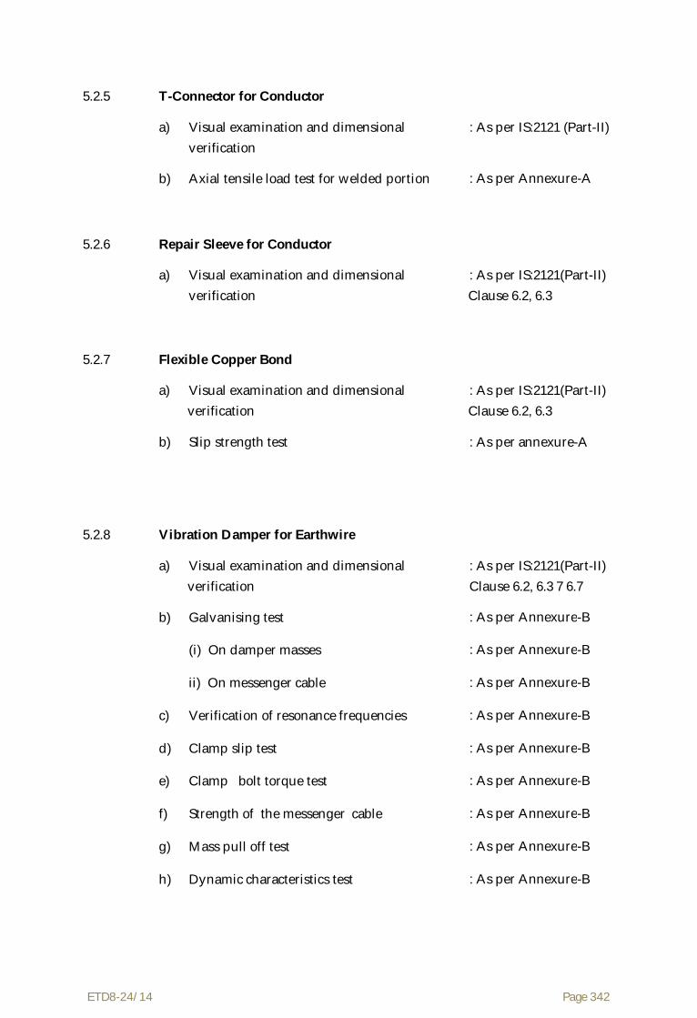
ETD8-24/14 Page 342
5.2.5 T-Connector for Conductor
a) Visual examination and dimensional verification
: As per IS:2121 (Part-II)
b) Axial tensile load test for welded portion : As per Annexure-A
5.2.6 Repair Sleeve for Conductor
a) Visual examination and dimensional verification
: As per IS:2121(Part-II) Clause 6.2, 6.3
5.2.7 Flexible Copper Bond
a) Visual examination and dimensional verification
: As per IS:2121(Part-II) Clause 6.2, 6.3
b) Slip strength test : As per annexure-A
5.2.8 Vibration Damper for Earthwire
a) Visual examination and dimensional verification
: As per IS:2121(Part-II) Clause 6.2, 6.3 7 6.7
b) Galvanising test : As per Annexure-B
(i) On damper masses : As per Annexure-B
ii) On messenger cable : As per Annexure-B
c) Verification of resonance frequencies : As per Annexure-B
d) Clamp slip test : As per Annexure-B
e) Clamp bolt torque test : As per Annexure-B
f) Strength of the messenger cable : As per Annexure-B
g) Mass pull off test : As per Annexure-B
h) Dynamic characteristics test : As per Annexure-B

ETD8-24/14 Page 343
5.2.9 Quad Spacer Damper for line / Rigid spacer for Jumper
a) Visual examination and dimensional verification
: As per IS:2121(Part-II) Clause 6.2, 6.3 7 6.7
b) Galvanising test : As per Annexure-B
c) Movement test (except for spacer jumpers) : As per Annexure-B
d) Clamp slip test : As per Annexure-B
e) Clamp bolt torque test : As per Annexure-B
f) Compression-tension test : As per Annexure-B
g) Assembly torque test : As per Annexure-B
h) Hardness test for elastomer ( if applicable) : As per Annexure-B
5.2.10 Earthwire Tension Clamp Assembly
a) Visual examination and dimensional verification
: As per IS:2121(Part-II)
b) Galvanising test : As per Annexure-A
c) Slip strength test for tension clamp : As per Annexure-A
d) Mechanical strength test on each component (excluding clamp)
: As per Annexure-A
e) Hardness test : As per Annexure-A
5.2.11 Earthwire Suspension Clamp Assembly
a) Visual examination and dimensional verification
: As per IS:2121(Part-II)
b) Galvanising test : As per Annexure-A
c) Clamp slip strength test : As per Annexure-A
d) Mechanical strength test on each component (excluding clamp)
: As per Annexure-A

ETD8-24/14 Page 344
5.3 Routine Tests
5.3.1 For Hardware Fittings
a) Visual examination IS:2486-(Part-I)
b) Proof Load Test : As per Annexure-A
5.3.1 For conductor and earthwire accessories
a) Visual examination and dimensional verification
: As per IS:2121(Part-II) Clause 6.2, 6.3 7 6.7
5.4 Tests During Manufacture on all components as applicable
a) Chemical analysis of Zinc used for galvanising
IS:2486-(Part-I)
b) Chemical analysis mechanical metallographic test and magnetic particle inspection for malleable castings
: As per Annexure-A
c) Chemical analysis, hardness tests and magnetic particle inspection for forging
: As per Annexure-A
5.5 Testing Expenses
5.5.1 Testing charges for the type test specified shall be indicated separately in the prescribed schedule.
5.5.2 Bidder shall indicate charges for all type tests covered under Clause No. 5.1.2 to 5.1.12 separately. The charges for each type test shall be separately indicated.
5.5.3 Testing charges for all type tests specified under clause no. 5.1.1 shall be indicated only by insulator Supplier's as the charges for these tests shall be paid to them duly by the Owner to avoid duplication and shall not be indicated by the hardware Supplier's.
5.5.4 For type tests which involve the tests on the complete insulator string with hardware fittings, the Contractor of hardware fittings shall supply the

ETD8-24/14 Page 345
necessary number of sets of hardware fittings at the place of testing free of cost.
5.5.5 In case of failure in any type test, the Bidder whose material has failed is either required to modify the design of the material & successfully carryout all the type tests as has been detailed out in Clause 5.1 of this specification or to repeat that particular type test at least three times successfully at his own expenses. In case of failure of the complete string in any type test, the manufacturer whose product has failed in the test shall get the test repeated at his cost. The Supplier whose material has not failed in the test shall be required to supply the requisite quantity of material (that is, insulator discs or hardware fittings as the case may be) required for repeat testing at the place of testing and the cost of supply shall be borne by the Contractor whose material has failed in testing.
5.5.6 Bidder shall indicate the laboratories in which they propose to conduct the type tests. They shall ensure that adequate facilities for conducting the tests are available in the laboratory and the tests can be completed in these laboratories within the time schedule guaranteed by them in the appropriate schedule.
5.5.7 The entire cost of testing for acceptance and routine tests and tests during manufacture specified herein shall be treated as included in the quoted Ex-works/CIF Price.
5.5.8 In case of failure in any type test, repeat type tests are required to be conducted, then, all the expenses for deputation of Inspector Owner’s representative shall be deducted from the contract price. Also if on receipt of the Contractor's notice of testing, the Owner’s representative/Inspector does not find 'plant' to be ready for testing the expenses incurred by the Owner for re-deputation shall be deducted from contract price.
5.5.9 The Contractor shall intimate the Owner about carrying out of the type tests along with detailed testing programme at least 3 weeks in advance (in case of Domestic Contractor and at least 6 weeks advance in case of Foreign Contractor) of the scheduled date of testing during which the Owner will arrange to depute his representative to be present at the time of carrying out the tests.
5.6 Sample Batch For Type Testing
5.6.1 The Contractor shall offer material for sample selection for type testing only after getting Quality Assurance Programme approved by the Owner. The Contractor shall offer at least three times the quantity of materials required for conducting all the type tests for sample selection. The sample for type

ETD8-24/14 Page 346
testing will be manufactured strictly in accordance with the Quality Assurance Programme approved by the Owner.
5.6.2 Before sample selection for type testing the Contractor shall be required to conduct all the acceptance tests successfully in presence of Owner's representative.
5.7 Schedule of Testing and Additional Tests
5.7.1 The Bidder has to indicate the schedule of following activities in their bids
(a) Submission of drawing for approval.
(b) Submission of Quality Assurance programme for approval.
(c) Offering of material for sample selection for type tests.
(d) Type testing.
5.7.2 The Owner reserves the right of having at his own expense any other test(s) of reasonable nature carried out at Contractor’s premises, at site, or in any other place in addition to the aforesaid type, acceptance and routine tests to satisfy himself that the material comply with the specifications.
5.7.3 The Owner also reserves the right to conduct all the tests mentioned in this specification at his own expense on the samples drawn from the site at Contractor’s premises or at any other test center. In case of evidence of non compliance, it shall be binding on the part of Contractor to prove the compliance of the items to the technical specifications by repeat tests, or correction of deficiencies, or replacement of defective items, all without any extra cost to the Owner.
5.8 Co-ordination for testing
The Contractors shall have to co-ordinate testing of their hardware fittings with insulators to be supplied by other Supplier to the Owner and shall have to also guarantee overall satisfactory performance of the hardware fittings with the insulators.
5.9 Test Reports
5.9.1 Copies of type test reports shall be furnished in at least six copies along with one original. One copy shall be returned duly certified by the Owner, only after which the commercial production of the concerned material shall start.
5.9.2 Copies of acceptance test report shall be furnished in at least six copies. One copy shall be returned, duly certified by the Owner, only after which the materials will be dispatched.

ETD8-24/14 Page 347
5.9.3 Record of routine test report shall be maintained by the Contractor at his works for periodic inspection by the Owner's representative.
5.9.4 Test certificates of tests during manufacture shall be maintained by the Contractor. These shall be produced for verification as and when desired by the Owner.
5.10 Inspection
5.10.1 The Owner's representative shall at all times be entitled to have access to the works and all places of manufacture, where the material and/or its component parts shall be manufactured and the representatives shall have full facilities for unrestricted inspection of the Contractor’s, sub-Contractor’s works raw materials. manufacturer’s of all the material and for conducting necessary tests as detailed herein.
5.10.2 The material for final inspection shall be offered by the Contractor only under packed condition as detailed in clause 5.11 of this part of the Specification. The engineer shall select samples at random from the packed lot for carrying out acceptance tests.
5.10.3 The Contractor shall keep the Owner informed in advance of the time of starting and of the progress of manufacture of material in its various stages so that arrangements could be made for inspection.
5.10.4 Material shall not be despatched from its point of manufacture before it has been satisfactorily inspected and tested unless the inspection is waived off by the Owner in writing. In the latter case also the material shall be despatched only after all tests specified herein have been satisfactorily completed.
5.10.5 The acceptance of any quantity of material shall in no way relieve the Contractor of his responsibility for meeting all the requirements of the Specification, and shall not prevent subsequent rejection, if such material are later found to be defective.
5.11 Packing and Marking
5.11.1 All material shall be packed in strong and weather resistant wooden cases/crates. The gross weight of the packing shall not normally exceed 200 Kg to avoid handling problems.
5.11.2 The packing shall be of sufficient strength to withstand rough handling during transit, storage at site and subsequent handling in the field.
5.11.3 Suitable cushioning, protective padding, dunnage or spacers shall be provided to prevent damage or deformation during transit and handling.

ETD8-24/14 Page 348
5.11.4 Bolts, nuts, washers, cotter pins, security clips and split pins etc. shall be packed duly installed and assembled with the respective parts and suitable measures shall be used to prevent their loss.
5.11.5 Each component part shall be legibly and indelibly marked with trade mark of the manufacturer.
5.11.6 All the packing cases shall be marked legibly and correctly so as to ensure safe arrival at their destination and to avoid the possibility of goods being lost or wrongly despatched on account of faulty packing and faulty or illegible markings. Each wooden case/crate shall have all the markings stenciled on it in indelible ink.
5.12 Standards
5.12.1 The Hardware fittings; conductor and earth wire accessories shall conform to the following Indian/International Standards which shall mean latest revisions, with amendments/ changes adopted and published, unless specifically stated otherwise in the Specification.
5.12.2 In the event of the supply of hardware fittings; conductor and earth wire accessories conforming to standards other than specified, the Bidder shall confirm in his bid that these standards are equivalent to those specified. In case of award, salient features of comparison between the Standards proposed by the Contractor and those specified in this document will be provided by the Contractor to establish their equivalence.
Sl. Indian Standard
Title International Standard
1. IS: 209-1992 Specification for zinc BS:3436-1986
2. IS:398-1992
Part-V
Aluminum Conductor Galvanised Steel- Reinforced For Extra High Voltage (400 KV) and above
IEC:1089-1991
BS:215-1970
3. IS 1573 Electroplated Coating of Zinc on iron and Steel
4. IS : 2121 (Part- Specification for Conductor and Earthwire Accessories for Overhead
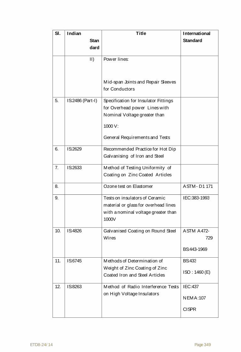
ETD8-24/14 Page 349
Sl. Indian Standard
Title International Standard
II) Power lines:
Mid-span Joints and Repair Sleeves for Conductors
5. IS:2486 (Part-I) Specification for Insulator Fittings for Overhead power Lines with Nominal Voltage greater than
1000 V:
General Requirements and Tests
6. IS:2629 Recommended Practice for Hot Dip Galvanising of Iron and Steel
7. IS:2633 Method of Testing Uniformity of Coating on Zinc Coated Articles
8. Ozone test on Elastomer ASTM- D1 171
9. Tests on insulators of Ceramic material or glass for overhead lines with a nominal voltage greater than 1000V
IEC:383-1993
10. IS:4826 Galvanised Coating on Round Steel Wires
ASTM A472-729
BS:443-1969
11. IS:6745 Methods of Determination of Weight of Zinc Coating of Zinc Coated Iron and Steel Articles
BS:433
ISO : 1460 (E)
12. IS:8263 Method of Radio Interference Tests on High Voltage Insulators
IEC:437
NEMA:107
CISPR

ETD8-24/14 Page 350
Sl. Indian Standard
Title International Standard
13. IS:6639 Hexagonal Bolts for Steel Structures ISO/R-272
14. IS:9708 Specification for Stock
15. IS:10162 Specification for Spacers Dampers for Twin Horizontal Bundle Conductors
The standards mentioned above are available from:
Reference Abbreviation
Name and Address
BS British Standards,
British Standards Institution
101, Pentonvile Road,
N - 19-ND
UK
IEC/CISPR International Electro technical Commission,
Bureau Central de la Commission,
electro Technique international,
1 Rue de verembe,
Geneva
SWITZERLAND
BIS/IS Beureau Of Indian Standards.
Manak Bhavan,
9, Bahadur Shah Zafar Marg,

ETD8-24/14 Page 351
New Delhi - 110001.
INDIA
ISO International Organisation for Standardization.
Danish Board of Standardization
Danish Standardizing Sraat,
Aurehoegvej-12
DK-2900, Heeleprup,
DENMARK.
NEMA National Electric Manufacture Association,
155, East 44th Street.
New York, NY 10017
U.S.A.

ETD8-24/14 Page 352
ANNEXURE - A
1.0 Tests on Complete Strings with Hardware Fittings
1.1 Voltage Distribution Test (For Insulator String with Disc Insulators)
The voltage across each insulator unit shall be measured by sphere gap method. The result obtained shall be converted into percentage. The voltage across any disc shall not exceed 9% for suspension insulator strings and 10% for tension insulator strings for 400 kV line.
1.2 Corona Extinction Voltage Test (Dry)
The sample assembly when subjected to power frequency voltage shall have a corona Extinction voltage of not less than 320 kV (rms) line to ground for 400 kV lines under dry condition. There shall be no evidence of corona on any part of the sample. The atmospheric condition during testing shall be recorded and the test results; shall be accordingly corrected with suitable correction factor as stipulated in IEC:60383.
1.3 RIV Test (Dry)
Under the conditions as specified under (1.2) above, the insulator string along with complete hardware fittings shall have a radio interference voltage level below 1000 micro volts at one MHz when subjected to 50 Hz AC voltage of 305 kV line to ground under dry condition for 400 kV line. The test procedure shall be in accordance with IS:8263/IEC:437.
1.4 Mechanical Strength Test
The complete insulator string along with its hardware fitting excluding arcing horn, corona control ring, grading ring and suspension assembly/dead end assembly shall be subjected to a load equal to 50% of the specified minimum ultimate tensile strength (UTS) which shall be increased at a steady rate to 67% of the minimum UTS specified. The load shall be held for five minutes and then removed. After removal of the load, the string components shall not show any visual deformation and it shall be possible to disassemble them by hand. Hand tools may be used to remove cotter pins and loosen the nuts initially. The string shall then be reassembled and loaded to 50% of UTS and the load shall be further increased at a steady rate till the specified minimum UTS and held for one minute. No fracture should occur during this period. The applied load shall then be increased until the failing load is reached and the value recorded.

ETD8-24/14 Page 353
1.5 Vibration Test
The suspension string shall be tested in suspension mode, and tension string in tension mode itself in laboratory span of minimum 30 meters. In the case of suspension string a load equal to 600 kg shall be applied along the axis of the suspension string by means of turn buckle. The insulator string along with hardware fittings and four sub conductors each tensioned at 43 KN shall be secured with clamps. The system shall be suitable to maintain constant tension on each sub-conductors throughout the duration of the test. Vibration dampers shall not be used on the test span. Both the sub-conductors shall be vertically vibrated simultaneously at one of the resonance frequencies of the insulators string (more than 10 Hz) by means of vibration inducing equipment. The peak to peak displacement in mm of vibration at the antinode point nearest to the string shall be measured and the same shall
not be less than 1000/f18 where f is the frequency of vibration in cycles/sec. The insulator string shall be vibrated for not less than 10 million cycles without any failure. After the test the disc insulators shall be examined for looseness of pins and cap or any crack in the cement. The hardware shall be examined for looseness, fatigue failure and mechanical strength test. There shall be no deterioration of properties of hardware components and disc insulators after the vibration test. The disc insulators shall be subjected to the following, tests as per relevant standards :
Sl. Test Percentage of insulator units to be tested
Disc Insulators Long Rod Insulators
a) Temperature cycle test followed by mechanical
performance test
60 100
b) Puncture test/steep wave front test (Only for glass insulators)
40 -

ETD8-24/14 Page 354
1.6 Power Arc test
This test shall be performed on the complete string in accordance with IEC Technical Report IEC : 61467-1997 with the following test series :
Test circuit Short circuit current Number and duration of test
B In = Isys = 40 KA Two of tn = 0.2s and
one of tn = 0.5s
The acceptance criteria after the completion of test series shall be following.
a) Insulator separation not permitted.
b) Burning/melting of metal components, breaking of insulator sheds, glaze removal are permitted.
c) The complete insulator string along with its hardware fittings including arcing horn, corona control ring/grading ring shall withstand 80% of UTS.
1.7 Assembly Test
This test shall be carried out to ensure that the cotter pins, bolts, clamps etc., fit freely and properly.
2.0 Tests on Hardware Fittings
2.1 Magnetic Power Loss Test for Suspension Assembly
For 400 kV line with Quad ACSR MOOSE conductor, four hollow aluminium tubes of 32 mm diameter shall be placed 457 mm apart. An alternating current over the range of 400 to 800 Amps for shall be passed through each tube. The reading of the wattmeter with and without two suspension assemblies along with line side yoke plate, clevis eye shall be recorded. Not less than three suspension assemblies shall be tested. The average power loss for suspension assembly. shall be plotted for each value of current. The value of the loss corresponding to 600 amperes shall be read off from the graph.
2.2 Galvanising/Electroplating Test
The test shall be carried out as per Clause no. 5.9 of IS:2486-(Part-1) - 1972 except that both uniformity of zinc coating and standard preece test shall be

ETD8-24/14 Page 355
carried out and the results obtained shall satisfy the requirements of this specification.
2.3 Mechanical Strength Test of Each Component
Each component shall be subjected to a load equal to the specified minimum ultimate tensile strength (UTS) which shall be increased at a steady rate to 67% of the minimum UTS specified. The load shall be held for five minutes and then removed. The component shall then again be loaded to 50% of UTS and the load shall be further increased at a steady rate till the specified UTS and held for one minute. No fracture should occur. The applied load shall then be increased until the failing load is reached and the value recorded.
2.4 Mechanical Strength Test of Welded Joint
The welded portion of the component shall be subjected to a Load of 2000 kgs for one minute. Thereafter, it shall be subjected to die-penetration/ultrasonic test. There shall not be any crack at the welded portion.
2.5 Clamp Slip Strength Vs Torque Test for Suspension Clamp
The suspension assembly shall be vertically suspended by means of a flexible attachment. A suitable length of ACSR conductor shall be fixed in the clamp. The clamp slip strength at various tightening torques shall be obtained by gradually applying the load at one end of the conductor. The Clamp slip strength vs. torque curve shall be drawn. The above procedure is applicable only for free center type suspension clamp. For AG suspension clamp only clamp slip strength after assembly shall be found out.
2.6 Shore Hardness Test for Elastomer Cushion for AG Suspension Assembly
The shore hardness at various points on the surface of the elastomer cushion shall be measured by a shore hardness meter and the shore hardness number shall be between 65 to 80.
2.7 Proof Load Test
Each component shall be subjected to a load equal to 50% of the specified minimum ultimate tensile strength which shall be increased at a steady rate to 67% of the UTS specified. The load shall be held for one minute and then removed. After removal of the load the component shall not show any visual deformation.
2.8 Tests for Forging Casting and Fabricated Hardware
The chemical analysis, hardness test, grain size, inclusion rating and magnetic particle inspection for forging, castings and chemical analysis and

ETD8-24/14 Page 356
proof load test for fabricated hardware shall be as per the internationally recognised procedures for these tests. The sampling will be based on heat number and heat treatment batch. The details regarding test will be as in the Quality Assurance programme.
2.9 Mechanical Strength Test for Suspension/Tension Hardware Fittings
The complete string without insulators excluding arcing horn, corona control rings/grading ring and suspension assembly/dead end assembly shall be subjected to a load equal to 50% of the specified minimum ultimate tensile strength (UTS) which shall be increased at a steady rate to 67% of the minimum UTS specified. This load shall be held for five minutes and then removed. After removal of the load, the string component shall not show any visual deformation and it shall be possible to disassemble them by hand. Hand tools may be used to remove cotter pins and loosen the nuts initially. The string shall then be reassembled and loaded to 50% of UTS and the load shall be further increased at a steady rate till the specified minimum UTS is reached and held for the one minute. No fracture should occur during this period. The applied load shall then be increased until the failing load is reached and the value recorded.
2.10 Ozone Test for Elastomer
This test shall be performed in accordance with ASTM D-1171 by the Ozone chamber exposure method (method B). The test duration shall be 500 hours and the ozone concentration 50 PPHM. At the test completion, there shall be no visible crack under a 2 x magnification.
3.0 Tests on Conductor and Earth wire Accessories
3.1 Mid Span Compression Joint for Conductor and Earth wire
(a) Slip Strength Test
The fitting compressed on conductor/earth wire shall not be less than one meter in length. The test shall be carried out as per IS:2121 (Part-II) clause 6.4 except that the load shall be steadily increased to 95% of minimum ultimate tensile strength of conductor/earth wire and retained for one minute at this load. There shall be no movement of the conductor/ earth wire relative to the fittings and no failure of the fit tings during this one minute period.
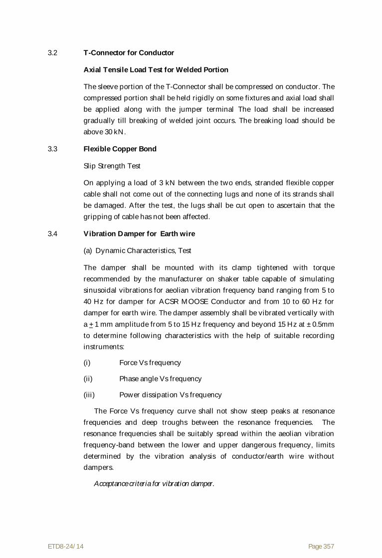
ETD8-24/14 Page 357
3.2 T-Connector for Conductor
Axial Tensile Load Test for Welded Portion
The sleeve portion of the T-Connector shall be compressed on conductor. The compressed portion shall be held rigidly on some fixtures and axial load shall be applied along with the jumper terminal The load shall be increased gradually till breaking of welded joint occurs. The breaking load should be above 30 kN.
3.3 Flexible Copper Bond
Slip Strength Test
On applying a load of 3 kN between the two ends, stranded flexible copper cable shall not come out of the connecting lugs and none of its strands shall be damaged. After the test, the lugs shall be cut open to ascertain that the gripping of cable has not been affected.
3.4 Vibration Damper for Earth wire
(a) Dynamic Characteristics, Test
The damper shall be mounted with its clamp tightened with torque recommended by the manufacturer on shaker table capable of simulating sinusoidal vibrations for aeolian vibration frequency band ranging from 5 to 40 Hz for damper for ACSR MOOSE Conductor and from 10 to 60 Hz for damper for earth wire. The damper assembly shall be vibrated vertically with a + 1 mm amplitude from 5 to 15 Hz frequency and beyond 15 Hz at ± 0.5mm to determine following characteristics with the help of suitable recording instruments:
(i) Force Vs frequency
(ii) Phase angle Vs frequency
(iii) Power dissipation Vs frequency
The Force Vs frequency curve shall not show steep peaks at resonance frequencies and deep troughs between the resonance frequencies. The resonance frequencies shall be suitably spread within the aeolian vibration frequency-band between the lower and upper dangerous frequency, limits determined by the vibration analysis of conductor/earth wire without dampers.
Acceptance criteria for vibration damper.

ETD8-24/14 Page 358
(i) The above dynamic characteristics test on five damper shall be conducted.
(ii) The mean reactance and phase angle Vs frequency curves shall be drawn with the criteria of best fit method.
(iii) The above mean reactance response curve should lie within following limits :
V.D. for MOOSE : 0.191 f to 0.762 f gf/mm
V.D. for 7/3.66Earth wire : 0.060 f to 0.357 f gf/mm
Where f is frequency in Hz.
(iv) The above mean phase angle response curve shall be between 25o to
130o within the frequency range of interest.
(v) If the above curve lies within the envelope, the damper design shall be considered to have successfully met the requirement.
(vi) Visual resonance frequencies of each mass of damper is to be recorded and to be compared with the guaranteed values.
(b) Vibration Analysis
The vibration analysis of the earthwire shall be done with and without damper installed on the span. The vibration analysis shall be done on a digital computer using energy balance approach. The following parameters shall be taken into account for the purpose of analysis :
(i) The analysis shall be borne for single conductor / earthwire without armour rods as per the parameters given under clause 2.5.13 and 3.3.8 of this part of the Specification. The tension shall be taken as 43 kN and 14 kN for ACSR MOOSE conductor and 7/3.66 mm earth wire respectively for a span ranging from 100 m to 1100 m.
(ii) The self damping factor and flexural stiffness (El) for earthwire shall be calculated on the basis of experimental results. The details of experimental analysis with these data should be furnished.
(iii) The power dissipation curve obtained from Dynamic Characteristics Test shall be used for analysis with damper.
(iv) Examine the aeolian vibration level of the earthwire with and without vibration damper installed at the recommended location or wind velocity ranging from 0 to 30 Km per hour, predicting amplitude, frequency and vibration energy input.

ETD8-24/14 Page 359
(v) From vibration analysis of earthwire without damper, antinode vibration amplitude and dynamic strain levels at clamped span extremities as well as antinodes shall be examined and thus lower and upper dangerous frequency limits between which the aeolian vibration levels exceed the specified limits shall be determined.
(vi) From vibration analysis of earthwire with damper/dampers installed at the recommended location, the dynamic strain level, at the clamped span extremities, damper attachment point and the antinodes on the earthwire shall be determined. In addition to above damper clamp vibration amplitude and antinode vibration amplitudes shall also be examined.
The dynamic strain levels at damper attachment points, clamped span extremities and antinodes shall not exceed the specified limits. The damper vibration amplitude shall not be more than that of the specified fatigue limits.
c) Clamp Slip and Fatigue Tests
(i) Test Set Up
The clamp slip and fatigue tests shall be conducted on a laboratory set up with a minimum effective span length of 30 m. The 7/3.66 mm earth wire at 14 and shall not be equipped with protective armour rods at any point. Constant tension shall be maintained within the span by means of lever arm arrangement. After the earthwire has been tensioned, clamps shall be installed to support the earthwire at both ends and thus influence of connecting hardware fittings are eliminated from the free span. The clamps shall not be used for holding the tension on the earthwire. There shall be no loose parts, such as suspension clamps, U bolts on the test span supported between clamps mentioned above. The span shall be equipped with vibration inducing equipment suitable for producing steady standing vibration. The inducing equipment shall have facilities for stepless speed control as well as stepless amplitude arrangement. Equipment shall be available for measuring the frequency, cumulative number of cycles and amplitude of vibration at any point along the span.
(ii) Clamp Slip test
The vibration damper shall be installed on the test span. The damper clamp, after lightning with the manufacturer’s specified tightening torque, when subjected to a longitudinal pull of 2.5 kN parallel to the axis of earthwire for a minimum duration of one minute shall not slip i.e. the permanent displacement between earthwire and clamp measured after removal of the

ETD8-24/14 Page 360
load shall not exceed 1.0 mm. The load shall be further increased till the clamp starts slipping. The load at which the clamp slips shall not be more than 5 kN.
(iii) Fatigue Test
The vibration damper shall be installed on the test span with the manufacturer’s specified tightening torque. It shall be ensured that the damper shall be kept minimum three loops away from the shaker to eliminate stray signals influencing damper movement.
The damper shall then be vibrated at the highest resonant frequency of each damper mass. For dampers involving torsional resonant frequencies, tests shall be done at torsional modes also in addition to the highest resonant frequencies at vertical modes. The resonance frequency shall be identified as the frequency at which each damper mass vibrates with the maximum amplitude on itself. The amplitude of vibration of the damper clamp shall be maintained not less than ± 25/f mm, where f is the frequency in Hz.
The test shall be conducted for minimum ten million cycles at each resonant frequency mentioned above. During the, test if resonance shift is observed the test frequency shall be tuned to the new resonant frequency.
The clamp slip test as mentioned hereinabove shall be repeated after fatigue test without retorquing or adjusting the damper clamp, and the clamp shall withstand a minimum load equal to 80% of the slip strength for a minimum duration of one minute.
After the above tests, the damper shall be removed from conductor/earthwire and subjected to dynamic characteristics test. There shall not be any major deterioration in the characteristic of the damper. The damper then shall be cut open and inspected. There shall not be any broken, loose, or damaged part. There shall not be significant deterioration or wear of the damper. The conductor/earthwire under clamp shall also be free from any damage.
For the purpose of acceptance, the following criteria shall be applied.
(1) There shall not be any frequency shift by more than +2 Hz for frequencies lower than 15 Hz and ± 3 Hz for frequencies higher than 15 Hz.
(2) The force response curve shall generally lie within guar anteed % variation in reactance after fatigue test in comparison with that before fatigue test by the Contractor.

ETD8-24/14 Page 361
(3) The power dissipation of the damper shall not be less than guaranteed % variation in power dissipation before fatigue test by the Contractor. However, it shall not be less than minimum power dissipation which shall be governed by lower limits of reactance and phase angle indicated in the envelope.
3.5 Spacer Damper
(a) Performance Test
One very important quality of a spacer damper is its ability to control Aeolian vibrations and sub-span oscillations within acceptable limits. Performance testing shall be carried out on an experimental test line, as described in Clause 2.5.3, Section-VI. After testing, there shall not be any slippage greater than 3mm on conductors, loosening of components or damage to conductors or spacer damper components.
i) Aeolian Vibrations
Under the specified operating conditions, the spacer damper shall control Aeolian vibrations in order to prevent damage to conductors either at suspensions clamp or at the spacer damper clamps.
For measurements and evaluation purpose, the following criteria shall apply:
- The peak to peak amplitude of any vibration cycle shall never exceed 1.5 Yb, where Yb is the safe “Bending Amplitude”.
- The RMS value of any vibration measurement sample shall be lower than 0.6 Yb/2, at 89mm from last point of contact with suspension or spacer clamp.
ii) Sub-span Oscillations
The spacer damper system shall control subspan oscillations in order to prevent conductor damage due to clashing or to severe bending stresses at the spacer damper clamp, and avoid wear of spacer dampers elements.
In order to achieve that performance level, subspan oscillation shall be controlled within the following limits, for any wind speed below 60 km/hr.
- In any individual subspan, the peak to peak amplitude of each subconductor shall never exceed 350mm.

ETD8-24/14 Page 362
- In any individual subspan, the RMS value (Y rms) of each oscillation measurement sample shall be such that:
f.Yrms < 80 mm/sec.
Where
Y (rms) = antinode amplitude (mm)
f = frequency of the oscillation (cycle/sec.)
f = (1/2L) sqrt (T/m)
L = subspan length (m)
T = Conductor tension (N)
m = conductor mass (kg/m)
For any set of 10 or more measurement samples associated with a given wind sector and a given subspan, the Y rms value shall be such that:
f. Yrms <70 mm/sec.
The wind sector is defined as a combination of 5 km/hr wind speed range and 10º wind direction range.
Each measurement sample shall be at least one (1) minute long.
(b) Clamp Slip Test (for spacer for jumper also)
The spacer damper assembly shall be installed on a four conductors bundle string at a tension of 43 kN. In case of spacer for jumper, the clamp of sample shall be tightened with a specified tightening torque. One of the sample clamps, when subjected to a longitudinal pull parallel to the conductor axis for a minimum duration of one minute, shall not slip on the conductor, i.e. the permanent displacement between the conductor and the clamp of the sample measured after removal of the load shall not exceed specified values. The minimum slip under longitudinal pull varies with clamp type according to the following table.
CLAMP TYPE LONGITUDINAL
LOAD (kN)
MAXIMUM
SLIP(mm)
Metal-Metal bolted 6.5 1
Rubber loaded 2.5 2.5

ETD8-24/14 Page 363
Clamp using
Preformed rods 2.5 12
In order to determine the effect of conductor creep with the spacer dampers only, the conductor shall be retensioned to 68 kN without further tightening the spacer damper clamps and the clamp slip test shall be reperformed. The minimum slip under longitudinal loads shall not be less than 80% of the values given in the above table.
Similar testing shall be performed of the other clamps of the same sample. For spacer dampers only, such clamp slip tests shall also be conducted after each of the vibration tests mentioned in Clause 3.5 (a) but under longitudinal loading corresponding to 80% of the values given in the above table.
c) Dynamic Characteristic Test for Spacer Damper
The purpose of this test is to obtain quantitative information regarding the dynamic characteristic of the spacer damper. The values obtained during this test will serve as references to evaluate the behaviour of the same spacer damper under the fatigue test.
The test will consist in the application of sinusoidal movement to the spacer damper articulation and measurement of the force (F), displacement (X) and phase angle (Ø) between these two. From these values, the stiffness (K) and damping faction (n) shall be calculated as:
The test frequency shall not be higher than 3 Hz. The test shall be performed at five different displacement amplitudes. The amplitudes shall be selected to reproduce 10, 20, 40, 60 and 90 percent of the maximum displacement permitted by the spacer damper design.
The test shall be performed on three samples.
In case of spacer dampers with a single articulation for each arm, the central body shall be applied between two arms corresponding to a horizontal pair of conductors. In this case, one spacer clamp may be fixed and the other displaced in its direction, the central body being free to move.
a) Fatigue Test for Spacer Damper
The purpose of this test is to evaluate the capacity of the spacer damper to sustain without damage the cyclic movements which can be induced by vibrations.

ETD8-24/14 Page 364
The spacer damper articulation shall be subjected to cyclic motions for a total of 10 million cycles. The test frequency shall be between 2 and 3 Hz. The amplitude of motion shall be established on the following basis:
- the load applied on the spacer damper clamp shall not be less than 300N;
- The clamp displacement under the applied load shall not be less than 60% of the maximum displacement permitted by the design;
- If the 300 N load generates movement exceeding the maximum permitted displacement, the load can be reduced to limit the movement to 95% of the maximum displacement.
After the test, the sample shall be subjected to a second dynamic characteristic test. The test shall be performed at two amplitudes, 10% and 60% of the maximum displacement.
The spacer damper shall show no signs of cracks or detoriation, loosening of bolts or abnormal wear.
The dynamic characteristics (k and n) shall not be less than 75% of the values measured before the fatigue test. The test shall be performed on three samples which have been previously subjected to dynamic characteristics test. Motion shall be as described in Dynamic Characteristic Test.
b) Ozone Test
This test shall be performed on elastomer/rubber components in accordance with ASTM D-1171 by the ozone chamber exposure method (method B). The test durations hall be 500 hours and the ozone concentration 50 PPHM. At the test completion, there shall be no visible crack under a 2xmagnification.
c) Compression and Tensile Tests
Three samples of spacer dampers shall be subjected to a tension compression test. The load shall be applied between each pair of diagonally opposed conductors. Under the compressive load, the arms shall be allowed to rotate until they reach their mechanical stops. A compressive load of 15 kN shall first be applied and held for five minutes. Then a tensile load of 5 kN shall be applied on the same pair of arms. The test shall be repeated on the other pair of arms. After the test, the spacer damper must be dismantled and the components examined. There should not be any failure of components or damage impairing the reusability of the spacer damper such as permanent deformation. The spacer geometry shall be maintained within 5% of the original dimensions.

ETD8-24/14 Page 365
3.6 Magnetic Power Loss Test for Spacer Damper/Spacer for jumper
The sample involving ferrous parts shall be tested in a manner to simulate service conditions for 50 Hz pure sine-wave. The test should be carried out at various currents ranging from 400 amperes to 800 amperes for 400 kV line and the magnetic power loss at various currents should be specified in tabulated graphical form. The difference between the power losses without and with sample at room temperature shall be limited to 1 watt for 600 amperes current (rms) for ACSR MOOSE Conductor. The losses shall be determined by averaging the observations obtained from at least four samples.
3.7 Mechanical Strength Test for Earthwire Suspension/Tension Clamp
(a) The suspension assembly/tension assembly (excluding tension clamp) shall be subjected to a load equal to 50% of the specified minimum ultimate tensile strength (UTS) which shall be increased at a steady rate to 67% of the minimum UTS specified. This load shall be held for five minutes and then removed. After removal of the load, the components shall not show any visual deformation and it shall be possible to disassemble them by hand. Hand tools may be used to loosen the nuts initially. The assembly shall then be reassembled and loaded to 50% of UTS and the load shall be further increased at a steady rate till the specified minimum UTS is reached and held for one minute. No fracture should occur during this period. The applied load shall then be increased until the failing load is reached and the value recorded.
(b) Clamp Slip Strength Vs Torque Test for Suspension Assembly
The suspension assembly shall be vertically suspended by means of a flexible attachment. A suitable length of Earthwire shall be fixed in the clamps. The clamp slip strength at various tightening torques shall be obtained by gradually applying the load at one end of the earthwire. The clamp slip strength Vs torque curve shall be drawn. The clamp slip strength at the recommended tightening torque shall be more than 12 kN but less than 17 kN for 7/3.66 mm earthwire.
(c) Slip Strength Test of Tension Clamp
Tension clamps shall be compressed on a 5 m length of earthwire on both ends. The assembly shall be mounted on a tensile testing machine and anchored in a manner similar to the arrangement to be used in service. A tensile load of 50% of the specified breaking load of the earthwire shall be applied & the sample shall be marked in such a way that movement

ETD8-24/14 Page 366
relative to the fitting can easily be detected. Without any subsequent adjustment of the fitting, the load shall be steadily increased to 95% of the specified breaking load and maintained for one minute. There shall be no movement of the earthwire relative to the fitting during this one minute period and no failure of the fitting also.
(d) Electrical Resistance Test of Tension Clamp
The tension clamp and the jumper shall be compressed on two suitable lengths of earthwire. The electrical resistance shall be measured between points on earthwire near the clamp and near the jumper mouth keeping 25 mm clearance of the fitting and should not exceed 75% of the measured resistance of equivalent length of earthwire. The test shall be conducted with direct current. The current connections shall be at a distance not less than 50 times the diameter of earthwire from the fitting and shall be made so that effective contact is ensured with all those strands of the earth wire which would be taken into account in calculating its equivalent resistance. The test shall be repeated with the polarity reversed and the average of the two results considered as the measured value.
3.8 Corona Extinction Voltage Test (Dry)
The sample when subjected to power frequency voltage shall have a corona extinction voltage of not less than 320 kV (rms) line to ground for 400 kV lines under dry condition for 400 kV line. There shall be no evidence of corona on any part of the sample. The atmospheric condition during testing shall be recorded and the test results shall be accordingly corrected with suitable correction factor as stipulated in IS:731.
3.9 Radio Interference Voltage Test (Dry)
Under the conditions as specified under (3.8) above, the sample shall have a radio interference voltage level below 1000 micro volts at one MHz when subjected to 50 Hz AC voltage of 305 kV rms line to ground under dry condition for 400 kV line. The test procedure shall be in accordance with IS:8263.
3.10 Chemical Analysis Test
Chemical analysis of the material used for manufacture of items shall be conducted to check the conformity of the same with Technical Specification and approved drawing.

ETD8-24/14 Page 367
4.0 Tests on All components (As applicable)
4.1 Chemical Analysis of Zinc used for Galvanizing
Samples taken from the zinc ingot shall be chemically analysed as per IS-209-1979. The purity of zinc shall not be less than 99.95%.
4.2 Tests for Forgings
The chemical analysis hardness tests and magnetic particle inspection for forgings, will be as per the internationally recognised procedures for these tests. The, sampling will be based on heat number and heat treatment batch. The details regarding test will be as discussed and mutually agreed to by the Contractor and Purchaser in Quality Assurance Programme.
4.3 Tests on Castings
The chemical analysis, mechanical and metallographic tests and magnetic particle inspection for castings will be as per the internationally recognised procedures for these tests. The samplings will be based on heat number and heat treatment batch. The details regarding test will be as discussed and mutually agreed to by the Contractor and Purchaser in Quality Assurance Programme.
ETD8-24/14 Page 368
ANNEXURE-B
Acceptance Tests
1 Mid Span Compression Joint for Conductor and Earthwire
(a) Hardness Test
The Brinnel hardness at various points on the steel sleeve of conductor core and of the earthwire compression joint and tension clamp shall be measured.
2. T-Connector for Conductor
(a) Axial Tensile Load Test for Welded Portion
Same as clause 3.2 of Annexure-A .
3. Flexible Copper Bond
(a) Slip Strength Test
Same as clause 3.3 of Annexure - A.
4. Vibration Damper for Earthwire
(a) Verification of Resonance Frequencies
The damper shall be mounted on a shaker table and vibrate at damper clamp displacement of +/-0.5 mm to determine the resonance frequencies. The resonance shall be visually identified as the frequency at which damper mass vibrates with maximum displacement on itself. The resonance frequency thus identified shall be compared with the guaranteed value. A tolerance of ± 1 Hz at a frequency lower than 15 Hz and ± 2 Hz at a frequency higher than 15 Hz only shall be allowed.
(b) Clamp Slip Test
Same as Clause 3.4 (c) (ii) of Annexure - A.
(c) Clamp Bolt Torque Test
The clamp shall be attached to a section of the earthwire. A torque of 150 percent of the manufacturer’s specified torque shall be applied to the bolt. There shall be no failure of component parts. The test set up is as described in Clause 3.4 (c) (i), Annexure-A.
(d) Strength of the Messenger Cable
The messenger cable shall be fixed in a suitable tensile testing machine and the tensile load shall be gradually applied until yield point is reached.

ETD8-24/14 Page 369
Alternatively, each strand of message caste may be fixed in a suitable tensile testing machine and the tensile load shall be gradually applied until yield point is reached. In such a case, the 95% of yield strength of each wire shall be added to get the total strength of the caste. The load shall be not less than the value guaranteed by the Contractor
(e) Mass Pull off Test
Each mass shall be pulled off in turn by fixing the mass in one jaw and the clamp in the other of a suitable tensile testing machine. The longitudinal pull shall be applied gradually until the mass begins to pull out of the messenger cable. The pull off loads shall not be less than the value guaranteed by the Contractor.
(f) Dynamic Characteristics Test
The test will be performed as acceptance test with the procedure mentioned for type test with sampling mentioned below
Vibration Damper:
- 1 Sample for 1000 Nos. & below Conductor
- 3 Samples for lot above 1 000 & up to 5000 nos.
- Additional 1 sample for every additional 1500 pieces above 5000.
The acceptance criteria will be as follows
(i) The above dynamic characteristics curve for reactance & phase angle will be done for frequency range of 10 Hz to 60 Hz for vibration damper for 7/3.66 mm earth wire.
(ii) If all the individual curve for dampers are within the envelope as already mentioned for type test for reactance & phase angle, the lot passes the test.
(iii) If individual results do not fall within the envelope, averaging of characteristics shall be done.
(a) Force of each damper corresponding to particular frequency shall be taken & average force of three dampers at the frequency calculated.
(b) Similar averaging shall be done for phase angle.

ETD8-24/14 Page 370
(c) Average force Vs frequency and average phase Vs frequency curves shall be plotted on graph paper. Curves of best fit shall be drawn for the entire frequency range.
(d) The above curves shall be within the envelope specified.
5. Spacer Damper/ Spacer for jumper
(a) Dynamic charactics Test
The test shall be carried out as per clause 3.5 (c) of Annexure-A.
(b) Movement Test
The spacer assembly shall be capable of the following movements without damaging the conductor, assuming one conductor is fixed and the other moving :
(i) Longitudinal movement ± 50 mm
parallel to the conductor
(ii) Vertical movement in a ± 25 mm
vertical direction at right
angle to the conductor
(iii) Torsional movement/angular ± 5 deg.
movement in a vertical plane
parallel to the conductor
(c) Compressive and Tensile Test
The spacer assembly shall withstand ultimate compressive load of 14 kN and tensile load of 7.0 kN applied between sub conductor bundle and held for one minute without failure. Line distance between clamps shall be recorded during each of the compression and tension test. Measurement shall be recorded at (i) no load (ii) with load (iii) after release of load. The center line distance under load shall be within ± 100 mm of the nominal design spacing. After release of load it shall be possible to retain the clamps at their original position using only slight hand pressure. There shall be no deformation or damage to the spacer assembly which would impair its function of maintaining the normal spacing.

ETD8-24/14 Page 371
(d) Clamp Slip Test
Same as clause 3.5(b) of Annexure-A.
(e) Clamp Bolt Torque Test
The spacer assembly shall be attached to conductor. A torque of 150 per cent of the manufacturer's specified tightening torque shall be applied to the clamp bolts or cap screws. There shall be no failure of the component parts.
(f) Assembly Torque Test
The spacer assembly shall be installed on conductor. The same shall not rotate on either clamp on applying a torque of 0.04 kN in clockwise or anti-clockwise direction.
(g) Hardness test for Elastomer
The shore hardness at different points on the elastomer surface of cushion grip clamp shall be measured by shore hardness meter. They shall lie between 65 to 80.
(h) UTS of Retaining Rods
The ultimate tensile strength of the retaining rods shall be measured. The value shall not be less than 35 kg/sq.mm.

ETD8-24/14 Page 372
SECTION-VII
DRAWINGS
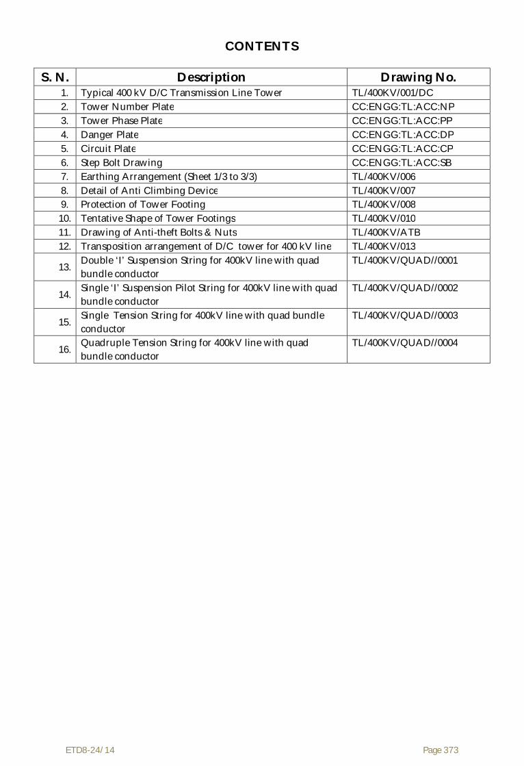
ETD8-24/14 Page 373
CONTENTS
S. N. Description Drawing No. 1. Typical 400 kV D/C Transmission Line Tower TL/400KV/001/DC 2. Tower Number Plate CC:ENGG:TL:ACC:NP 3. Tower Phase Plate CC:ENGG:TL:ACC:PP 4. Danger Plate CC:ENGG:TL:ACC:DP 5. Circuit Plate CC:ENGG:TL:ACC:CP 6. Step Bolt Drawing CC:ENGG:TL:ACC:SB 7. Earthing Arrangement (Sheet 1/3 to 3/3) TL/400KV/006 8. Detail of Anti Climbing Device TL/400KV/007 9. Protection of Tower Footing TL/400KV/008 10. Tentative Shape of Tower Footings TL/400KV/010 11. Drawing of Anti-theft Bolts & Nuts TL/400KV/ATB 12. Transposition arrangement of D/C tower for 400 kV line TL/400KV/013
13. Double ‘I’ Suspension String for 400kV line with quad bundle conductor
TL/400KV/QUAD//0001
14. Single ‘I’ Suspension Pilot String for 400kV line with quad bundle conductor
TL/400KV/QUAD//0002
15. Single Tension String for 400kV line with quad bundle conductor
TL/400KV/QUAD//0003
16. Quadruple Tension String for 400kV line with quad bundle conductor
TL/400KV/QUAD//0004

ETD8-24/14 Page 374

ETD8-24/14 Page 375
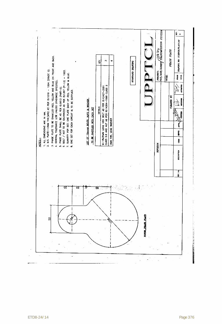
ETD8-24/14 Page 376

ETD8-24/14 Page 377

ETD8-24/14 Page 378

ETD8-24/14 Page 379

ETD8-24/14 Page 380

ETD8-24/14 Page 381

ETD8-24/14 Page 382
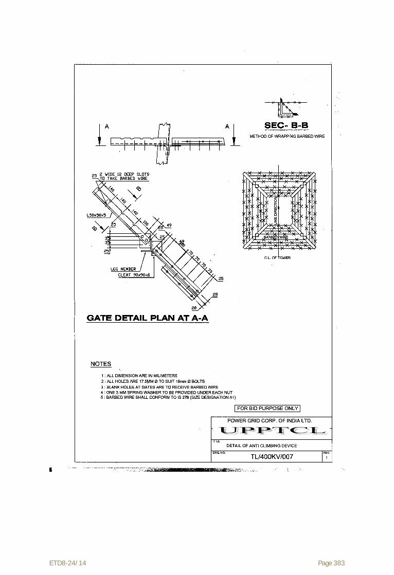
ETD8-24/14 Page 383

ETD8-24/14 Page 384

ETD8-24/14 Page 385

ETD8-24/14 Page 386

ETD8-24/14 Page 387

ETD8-24/14 Page 388

ETD8-24/14 Page 389

ETD8-24/14 Page 390
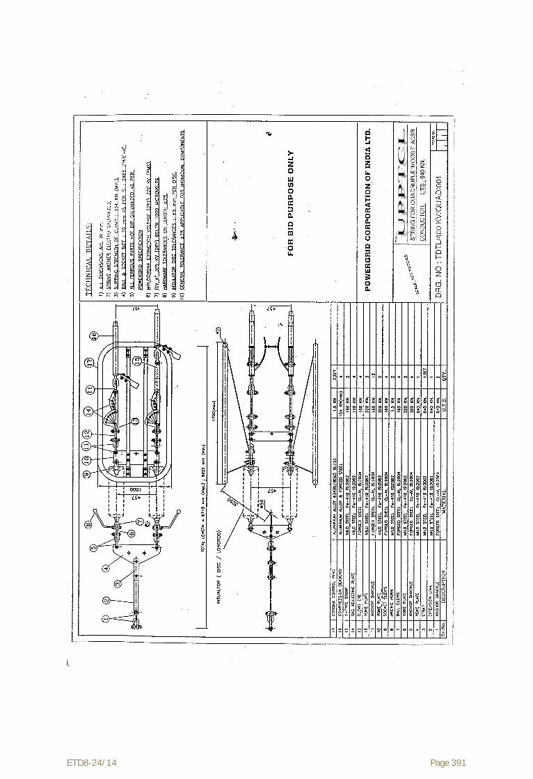
ETD8-24/14 Page 391
ETD8-24/14 Page 392
Volume – II
TECHNICAL SPECIFICATIONS OF OPGW AND ITS HARDWARE & ACCESSORIES
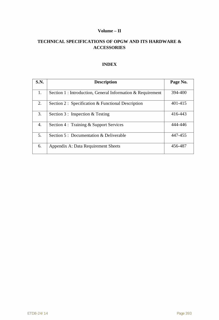
ETD8-24/14 Page 393
Volume – II
TECHNICAL SPECIFICATIONS OF OPGW AND ITS HARDWARE & ACCESSORIES
INDEX
S.N. Description Page No.
1. Section 1 : Introduction, General Information & Requirement
394-400
2. Section 2 : Specification & Functional Description
401-415
3. Section 3 : Inspection & Testing
416-443
4. Section 4 : Training & Support Services
444-446
5. Section 5 : Documentation & Deliverable
447-455
6. Appendix A: Data Requirement Sheets
456-487

ETD8-24/14 Page 394
Section-1
Introduction, General Information and Requirement

ETD8-24/14 Page 395
Section 1 Introduction, General Information and Requirement
This Volume II of the Bid Documents describes the technical specifications for procurement of overhead fibre optic cable (OPGW) for 400 kV DC Transmission system to be referred as OPGW Package being implemented as a part of UPPTCL Transmission Line Project.This specification describes the functional and performance requirements of the OPGW system. The intent of this Package is to implement a OPGW fibre optic cable supporting the capacity requirements as well as to provide an expansion capability. The Contractor shall be responsible for installation/erection of OPGW.
The purpose of this section of the specification is to provide introduction, general information, and general requirement and define the scope of the package. 1.1 Introduction UPPTCL is laying new 400 kV SC transmission lines with Quad ACSR MOOSE Conductor. 24 Fibre (DWSM, G.652D) Optical Ground Wire (OPGW) cable shall be laid on these 400 kV SC transmission lines.The Contractor shall supply & Lay( Stringing) 24 fibre OPGW cable along with hardware & fittings on 400 kV SC transmission lines. The installation of OPGW cable shall be carried out by the contractor. The supervision of Erection, Splicing, Termination, Testing and Commissioning of OPGW is included in the scope.
1.2 Scope and General Requirements
The scope of this Package shall include the planning, design, engineering, supply, erection/installation of OPGW cable, splicing, termination, training, testing, demonstration for acceptance, commissioning and documentation of:
(i.) Supply of 24 fibre OPGW cable along with hardware & fittings (ii.) Supervision of Erection of OPGW cable
(iii.) Survey for approach cable (iv.) Testing & Commissioning of fibre optic cable (v.) Supply & Installation of Joint box, Approach cable & FODP
(vi.) Splicing of fibres after installation of OPGW cable (vii.) All associated hardware, fittings and accessories (Tension assembly,
Suspension assembly, Vibration dampers, Reinforcing rods, Earthing clamps, Downlead clamps etc.) required for installation of OPGW cable.
The Contractor shall be responsible for testing of OPGW cable drum before stringing. Testing after installation of OPGW cable and end to end testing and Commissioning of fibre optic cable.
After completion of survey the contractor shall prepare drum schedule/detailed engineering as per tower schedule and mechanical loadings. The erection/installation of OPGW cable for 400 kV SC Transmission system shall be carried out by the Contractor.

ETD8-24/14 Page 396
The various Sections of this specification define the design, performance, test and implementation requirements for OPGW Cable system.
1.3 General Requirements The Contractor is encouraged to offer standard products and designs. However, the Contractor must conform to the requirements and provide any special equipment necessary to meet the requirements stated herein.
It should be noted that preliminary design information and bill of quantity (BOQ) specified in the Schedule – O are indicative only. The Contractor shall verify the design data during detailed engineering and finalise the BOQ as required for ultimate design & system performance. The Employer reserves the right of execution of works at actual other than those indicated in the appendices at the same rates, terms and conditions.
The Bidder's proposal shall address all functional and performance requirements within this specification and shall include sufficient information and supporting documentation in order to determine compliance with this specification without further necessity for inquiries.
The Bidder's proposal shall clearly identify all features described in the specifications or in any supporting reference material that will not be implemented; otherwise, those features shall become binding as part of the final contract.
An analysis of the functional and performance requirements of this specification, design, and engineering may lead the Contractor to conclude that additional items are required that are not specifically mentioned in this specification. The Contractor shall be responsible for providing at no added cost to the Employer, all such additional items such that a viable and fully functional Overhead Fibre Optic Cable System is implemented that meets or exceeds the capacity, and performance requirements specified. Such materials shall be considered to be within the scope of the contract. To the extent possible, the Bidders shall identify and include all such additional items in their proposal.
The offered items shall be designed to operate in varying environments. Adequate measures shall be taken to provide protection against rodents, contaminants, pollutants, water & moisture, lightning & short circuit, vibration and electro-magnetic interference etc.
The Contractor shall demonstrate a specified level of performance of the offered items during well structured factory and field tests.
1.4 General Responsibilities and Obligations This section describes the general responsibilities and obligations of the Contractor and the Employer.

ETD8-24/14 Page 397
1.4.1 Responsibilities for the Implementation Plan The Bidder's technical proposal shall include a project implementation plan and schedule that is consistent with the implementation plan detailed in Technical Specifications. The implementation plan shall be modelled such that it provides fibre optic cabling system support for the UPPTCL Transmission Line Project. The Implementation plan shall include the activities of both the Contractor and the Employer, showing all key milestones and clearly identifying the nature of all information and project support expected from the Employer. The Employer and Contractor shall finalise the detailed Implementation plan following award of the contract.
1.4.2 Contractor's Responsibilities and Obligations Contractor's obligations include, but are not limited to, the following:
(1) Provide a working system that meets the functional and performance requirements of this specification.
(2) Engineering and design including review of and conformance with local environmental and earthing requirements.
(3) Inputs for finalisation of installation and safety guidelines and procedures for the stringing, mechanical installation
(4) Development of installation and safety guidelines and procedures for the complete system.
(5) Development of procedure for splicing of all fibre optic cable, including testing and documentation.
(6) Project management, project scheduling, including monthly project reports documenting progress during the contract period.
(7) Engineering and technical assistance during the contract and warranty period (8) Site visits and studies as required. (9) Testing & Splicing of fibres as required (10) Factory and site acceptance testing. (11) Provide documented evidence of satisfactory Type Tests performance. (12) Provide a Quality Assurance Plan ensuring the Employer access to the
manufacturing process. (13) Shipment of all equipment and documentation to the Employer designated
locations and/or staging areas. (14) Installation of FODP & Joint Boxes. (15) All documentation and drawings as specified. (16) All required spare parts, maintenance aids, etc. (17) Training on OPGW Cable, Hardware & fittings, Splicing etc. (18) Due diligence in proper planning and executing the work so as to minimise
any physical damage. (19) The Contractor shall appoint key personnel for the OPGW Package such as
Project Manager, Site Manager, Design Engineer, Installation Engineer and Commissioning Engineer.
(20) Availability of service, spare and expansion parts for the life of equipment.

ETD8-24/14 Page 398
Detailed descriptions of the Contractor's obligations, in relation to individual items and services offered, are delineated in other sections of this specification.
1.4.3 The Employer Responsibilities and Obligations The Employer will provide the following items and services:
(1) Review and approval of the Contractor's designs, drawings, survey reports and recommendations.
(2) Review and approval of test procedures.
(3) Participation in and approval of factory and site acceptance tests.
(4) Providing support and access to facilities at the sites.
(5) Assistance in obtaining statutory clearances from regulatory bodies.
(6) Approval of key personnel for the project.
(7) Overall project management of the project
1.5 General Bidding Requirements The Bidder shall be responsive to the technical requirements as set forth in this specification. The Bidder's proposal shall include the following:
(1) The Technical Proposal including the documents listed in the table 1-1: Bid Documents Checklist shall be provided in the bid.
(2) A detailed project implementation plan and schedule that is consistent with the scope of the project and Employer's specified objectives. The plan shall include the activities of the Contractor, show all key milestones, and clearly identify the nature of all information and project support to be provided by Employer.
(3) A commitment and a clearly defined plan to provide system support in India and capability of providing a full range of local services for the life of the delivered systems.
Table 1-1
S. No.
Description:
Enclosure Reference
1
Type Test Certificates for offered items.
(As per relevant Sections of Technical Specs Volume II)
Page no.
Ref no.
2
Completed Data Requirement Sheets
(As per Appendix- A of Technical Spec Volume II)
Page no.
Ref no.
ETD8-24/14 Page 399
S. No.
Description:
Enclosure Reference
3
Quality Assurance Program
(As per relevant Sections of Technical Specs Volume II)
Page no.
Ref no.
4
Technical Brouchers/details of the offered items
Page no.
Ref no.
5 Detailed Project Implementation Plan
(As per relevant Sections of Technical Specs Volume II)
Page no.
Ref no.
1.6 Organization of the Technical Specification Document
Sections 2 to 5 provide the project requirements of the fibre optic cabling system to be provided.
Section 2 contains the specifications and functional description
Section 3 contains the specification for Inspection and Testing
Section 4 contains the specification for Training and Support Services
Section 5 contains the documentation and deliverables
The following is a list of the Volume II Appendices: Appendix A - Data Requirement Sheets
1.7 Applicable Standards The applicable standards are mentioned in the respective technical section. The offered cable/item shall conform to the standards mentioned in the specification except to the extent modified by this specification. In case of any discrepancy between the description given in the specification and the standards, the provisions of the technical specification shall be followed. The parameters not specifically mentioned in this specification shall conform to the standard mentioned in this specification. Specifications and codes shall be the latest version, inclusive of revisions, which are in force at the date of the contract award. Where new specifications, codes, and revisions are issued during the period of the contract, the Contractor shall attempt to comply with such, provided that no additional expenses are charged to the Employer without Employer’s written consent.

ETD8-24/14 Page 400
In the event the Contractor offers to supply material and/or equipment in compliance to any standard other than Standards listed herein, the Contractor shall include with their proposal, full salient characteristics of the new standard for comparison.
In case values indicated for certain parameters in the specifications are more stringent than those specified by the standards, the specification shall override the standards.
1.8 References (1) CIGRE Guide for Planning of Power Utility Digital Communications
Networks
(2) CIGRE Optical Fibre Planning Guide for Power Utilities
(3) CIGRE New Opportunities for Optical Fibre Technology in Electricity Utilities
(4) CIGRE guide to fittings for Optical Cables on Transmission Lines
ETD8-24/14 Page 401
Section-2
Specifications and Functional Description

ETD8-24/14 Page 402
Section - 2
Specifications and Functional Description This section describes the functional & technical specifications of overhead fibre optic cable (OPGW) and associated hardware & fittings.
2.1 Fibre Optic Cabling This section defines the requirements for G.652D Dual-window Single mode (DWSM) telecommunications grade fibre optic cable. Bidders shall furnish with their bids, detailed descriptions of the fibres & cable(s) proposed.
All optical fibre cabling including fibre itselfand all associated installation hardware shall have a minimum guaranteed design life span of 25 years.
2.1.1 Required Optical Fibre Characteristics This section describes the characteristics of optical fibre to be provided under this specification.
2.1.1.1 Physical Characteristics Dual-Window Single mode (DWSM) optical fibres shall be provided in the fibre optic cables. DWSM optical fibres shall meet the requirements defined in Table 2-1(a).
2.1.1.2 Attenuation The attenuation coefficient for wavelengths between 1525 nm and 1575 nm shall not exceed the attenuation coefficient at 1550 nm by more than 0.05 dB/km. The attenuation coefficient between 1285 nm and 1330 nm shall not exceed the attenuation coefficient at 1310 nm by more than 0.05 dB/km. The attenuation of the fibre shall be distributed uniformly throughout its length such that there are no point discontinuities in excess of 0.10 dB. The fibre attenuation characteristics specified in table 2-1(a) shall be “guaranteed” fibre attenuation of any & every fibre reel.
The overall optical fibre path attenuation shall not be more than calculated below:
Maximum attenuation @ 1550nm: 0.21dB/km x total km + 0.05 dB/splice x no. of splices + 0.5 dB/connector x no. of connectors
Maximum attenuation @ 1310nm: 0.35dB/km x total km + 0.05 dB/splice x no. of splices + 0.5 dB/connector x no. of connectors

ETD8-24/14 Page 403
Table 2-1(a)
DWSM Optical Fibre Characteristics
Fibre Description:
Dual-Window Single-Mode
Mode Field Diameter:
8.6 to 9.5 m (± 0.6m )
Cladding Diameter:
125.0 m ± 1m
Mode field concentricity error
0.6m
Cladding non-circularity
≤ 1%
Cable Cut-off Wavelength cc
≤ 1260 mm
1550 nm loss performance
As per G.652 D
Proof Test Level
≤ 0.69 Gpa
Attenuation Coefficient:
@ 1310 nm ≤ 0.35dB/km
@ 1550 nm ≤ 0.21dB/km
Chromatic Dispersion; Maximum:
Zero Dispersion Wavelength:
Zero Dispersion Slope:
18 ps/(nm x km) @ 1550 nm
3.5 ps/(nm x km) 1288-1339nm
5.3 ps/(nm x km) 1271-1360nm
1300 to 1324nm
0.092ps/(nm2xkm) maximum Polarization mode dispersion coefficient
≤ 0.2 ps/km^½
Temperature Dependence:
Induced attenuation ≤ 0.05 dB (-600C - +850C )

ETD8-24/14 Page 404
2.1.2 Fibre Optic Cable Construction Overhead Fibre Optic Cables shall be OPGW (Optical Ground Wire). The OPGW cable is proposed to be installed on the 400 kV DC Transmission Lines. The design of cable shall account for the varying operating and environmental conditions that the cable shall experience while in service.
2.1.2.1 Optical Fibre Cable Link Lengths The estimated optical fibre link lengths are provided in Schedule – O-1 & O-2. However, the Contractor shall supply the OPGW cable as required based on the tower schedule.
For the purpose of payment, the optical fibre link lengths are defined as transmission line route lengths from Gantry at one terminating station to the Gantry in the other terminating station. The actual cable lengths to be delivered shall take into account various factors such as sag, service loops, splicing, working lengths & wastage etc. and no additional payment shall be payable in this regard. The unit rate for FO cable quoted in the Bid price Schedules shall take into account all such factors.
2.1.2.2 Optical Fibre Identification Individual optical fibres within a fibre unit and fibre units shall be identifiable in accordance with EIA/TIA 598 or IEC 60304 or Bellcore GR-20 colour-coding scheme.
Colouring utilized for colour coding optical fibres shall be integrated into the fibre coating and shall be homogenous. The colour shall not bleed from one fibre to another and shall not fade during fibre preparation for termination or splicing.
Each cable shall have traceability of each fibre back to the original fibre manufacturer's fibre number and parameters of the fibre. If more than the specified number of fibres are included in any cable, the spare fibres shall be tested by the cable manufacturer and any defective fibres shall be suitably bundled, tagged and identified at the factory by the vendor.
Bend Performance:
@ 1310 nm (75±2 mm dia Mandrel), 100 turns;
Attenuation Rise ≤ 0.05 dB/km
@ 1550 nm (75±2 mm dia Mandrel), 100 turns;
Attenuation Rise≤0.10 dB/km
@ 1550 nm (32±0.5 mm dia Mandrel, 1 turn;
Attenuation Rise≤ 0.50 dB/km

ETD8-24/14 Page 405
2.1.2.3 Buffer Tube Loose tube construction shall be implemented. The individually coated optical fibre(s) shall be surrounded by a buffer for protection from physical damage during fabrication, installation and operation of the cable. The fibre coating and buffer shall be strippable for splicing and termination. Each fibre unit shall be individually identifiable utilizing colour coding. Buffer tubes shall be filled with a water-blocking gel.
2.1.2.4 Optical Fibre Strain & Sag-tension chart The fibre optic cable shall be designed and installed such that the optical fibres experience no strain under all loading conditions defined in IS 802. Zero fibre strain condition shall apply even after a 25 year cable creep.
For the purpose of this specifications, the following definitions shall apply:
Maximum Working Tension (MWT) is defined as the maximum cable tension at which there is no fibre strain.
The no fibre strain condition is defined as fibre strain of less than or equal to 0.05%, as determined by direct measurements through IEC/ ETSI (FOTP) specified optical reflectometry techniques.
The Cable strain margin is defined as the maximum cable strain at which there is no fibre strain.
The cable Maximum Allowable Tension (MAT) is defined as the maximum tension experienced by the Cable under the worst case loading condition.
The cable max strain is defined as the maximum strain experienced by the Cable under the worst case loading condition.
The cable Every Day Tension (EDT) is defined as the maximum cable tension on any span under normal conditions.
The Ultimate /Rated Tensile Strength (UTS/ RTS/ breaking strength) is defined as the maximum tensile load applied and held constant for one minute at which the specimen shall not break.
While preparing the Sag-tension charts for the OPGW cable the following conditions shall be met:
The Max Allowable Tension (MAT) / max strain shall be less than or equal to the MWT/ Strain margin of the cable.
The sag shall not exceed the earth wire sag in all conditions. The Max Allowable Tension shall also be less than or equal to 0.4 times the
UTS. The 25 year creep at 25% of UTS (creep test as per IEEE 1138) shall be such
that the 25 year creep plus the cable strain at Max Allowable Tension (MAT) is less than or equal to the cable strain margin.
The everyday tension (EDT) shall not exceed 20% of the UTS for the OPGW cable.

ETD8-24/14 Page 406
The Sag-tension chart of OPGW cable indicating the maximum tension, cable strain and sag shall be calculated and submitted along with the bid for 400m span under various conditions mentioned below:
1. 0°C, no wind and no ice 2. 32° C, no wind and no ice (EDT) 3. 0° C, 36% full wind and no ice 4. 32° C, full wind and no ice 5. 53° C , no wind and no ice 6. 32° C, 50 % full wind and no ice
The size of OPGW shall be selected such that max tension and sag at specified temperature and wind condition remain within the limits indicated below:
S. N. Parameter For 47 m/sec Wind Zone-4
1. Basic Span 400 m
2. Wind Pressure 201.201 kg/sq-m
3. Overall Diameter 0.01098 m
4. Unit Weight 0.583 kg/m
5. Ultimate Tensile Strength 6972 kg
6. Tension at 32° C& Full wind
3374.27 kg
7. Sag at 53° C & no wind 10.199 m
8. Sag at 0° C& no wind 8.702 m
The above cases shall be considered for the spans from 100 m to 600 m in the range of 50 m spans. The full wind load shall be considered as the design wind load for all the specified transmission lines as per relevant IS 802 version and the sag-tension chart shall be submitted considering the transmission lines. The stringing chart shall be submitted by the Tower Package Contractor for transmission line. However, the same shall be reviewed by this package Contractor and the Employer. For existing AC line, stringing chart shall be submitted by the Contractor for review of Employer.
2.1.2.5 Cable Materials The materials used for optical fibre cable construction, shall meet the following requirements:
2.1.2.5.1 Filling Materials The interstices of the fibre optic unit and cable shall be filled with a suitable compound to prohibit any moisture ingress or any water longitudinal migration within the fibre optic
ETD8-24/14 Page 407
unit or along the fibre optic cable. The water tightness of the cable shall meet or exceed the test performance criteria as per IEC-794-1-F-5.
The filling compound used shall be a non-toxic homogenous waterproofing compound that is free of dirt and foreign matter, nonhygroscopic, electrically nonconductive and non-nutritive to fungus. The compound shall also be fully compatible with all cable components it may come in contact with and shall inhibit the generation of hydrogen within the cable.
The waterproofing filling materials shall not affect fibre coating, colour coding, or encapsulant commonly used in splice enclosures, shall be dermatologically safe, non-staining and easily removable with a non-toxic cleaning solvent.
2.1.2.5.2 Metallic Members When the fibre optic cable design incorporates metallic elements in its construction, all metallic elements shall be electrically continuous.
2.1.2.5.3 Marking, Packaging and Shipping This section describes the requirements for marking, packaging and shipping the overhead fibre optic cable.
(a) Drum Markings: Each side of every reel of cable shall be permanently marked in white lettering with the vendors' address, the Purchaser’s destination address, cable part number and specification as to the type of cable, length, number of fibres, a unique drum number including the name of the transmission line & segment no., factory inspection stamp and date.
(b) Cable Drums: All optical fibre cabling shall be supplied on strong drums provided with lagging of adequate strength, constructed to protect the cabling against all damage and displacement during transit, storage and subsequent handling during installation. Both ends of the cable shall be sealed as to prevent the escape of filling compounds and dust & moisture ingress during shipment and handling. Spare cable caps shall be provided with each drum as required.
The spare cable shall be supplied on sturdy, corrosion resistant, steel drums suitable for long periods of storage and re-transport & handling.
There shall be no factory splices allowed within a continuous length of cable. Only one continuous cable length shall be provided on each drum. The lengths of cable to be supplied on each drum shall be determined by a "schedule" prepared by the Contractor.
2.1.2.6 Optical Ground Wire (OPGW) OPGW cable construction shall comply with IEEE-P1138,1994 and IEC publication 1396. The cable provided shall meet both the construction and performance requirements such that the ground wire function, the optical fibre integrity and optical transmission characteristics are suitable for the intended purpose. The cable shall consist of optical

ETD8-24/14 Page 408
fibre units as defined in paragraphs 2.1.2.3 through 2.1.2.4. There shall be no factory splices within the cable structure of a continuous cable length.
The composite fibre optic overhead ground wire shall be made up of buffered optical fibre units embedded in a water tight aluminium / aluminium alloy/stainless steel protective central fibre optic unit surrounded by concentric-lay stranded metallic wires in single or multiple layers. The dual purpose of the composite cable is to provide the electrical and physical characteristics of conventional overhead ground wire while providing the optical transmission properties of optical fibre.
2.1.2.6.1 Central Fibre Optic Unit The central fibre optic unit shall be designed to house and protect multiple buffered optical fibre units from damage due to forces such as crushing, bending, twisting, tensile stress and moisture. The central fibre optic unit and the outer stranded metallic conductors shall serve together as an integral unit to protect the optical fibres from degradation due to vibration and galloping, wind and ice loadings, wide temperature variations, lightning and fault current, as well as environmental effects which may produce hydrogen.
The OPGW design of dissimilar materials such as stainless steel tube with aluminium or aluminium –clad-steel wire strands are not allowed. Central fibre optic unit may be of aluminium or stainless steel tube with aluminium protective coating. In case of aluminium protective coating, the coating must completely cover the tubes leaving no exposed areas of tubing that can make electrical contact either directly or indirectly through moisture, contamination, protrusions, etc with the surrounding stranded wires. The tube may be fabricated as a seamless tube, seam welded, or a tube without a welded seam.
2.1.2.6.2 Basic Construction The cable construction shall conform to the applicable requirements of Section 2.1.2, applicable clauses of IEC 61089 related to stranded conductors and Table 2.2(a) OPGW Mechanical and Electrical Characteristics. In addition, the basic construction shall include bare concentric-lay-stranded metallic wires with the outer layer having left hand lay. The wires may be of multiple layers with a combination of various metallic wires within each layer. The direction of lay for each successive layer shall be reversed. The finished wires shall contain no joints or splices unless otherwise agreed to by the Employer and shall conform to all applicable clauses of IEC 61089 as they pertain to stranded conductors.
The wires shall be so stranded that when the complete OPGW is cut, the individual wires can be readily regrouped and then held in place by one hand.

ETD8-24/14 Page 409
2.1.2.6.3 Breaking Strength The rated breaking strength of the completed OPGW shall be taken as no more than 90 percent of the sum of the rated breaking strengths of the individual wires, calculated from their nominal diameter and the specified minimum tensile strength.
The rated breaking strength shall not include the strength of the optical unit. The fibre optic unit shall not be considered a load bearing tension member when determining the total rated breaking strength of the composite conductor.
2.1.2.6.4 Electrical and Mechanical Requirements Table 2-2(a) provides OPGW Electrical and Mechanical Requirements for the minimum performance characteristics. For the purposes of determining the appropriate Max Working Tension limit for the OPGW cableIS 802:1995 and IS 875: 1987 shall be applied. However the OPGW installation sag & tension charts shall be based on IS 802 version to which the line is originally designed. For the OPGW cable design selection and preparation of sag tension charts, the limits specified in clause 2.1.2.4 shall also be satisfied. The Bidder shall submit sag-tension charts for the above cases with their bids.
Table 2.2(a)
OPGW Electrical and Mechanical Requirements
(1) Everyday Tension ≤ 20% of UTS of OPGW
(2) D.C. Resistance at 200C: < 1.0 ohm/Km
(3) Short Circuit Current: ≤ 6.32 kA for 1.0 second
2.1.2.6.5 Operating conditions Since OPGW shall be located at the top of the EHV transmission line support structure, it will be subjected to Aeolian vibration, Galloping and Lightning strikes. It will also carry ground fault currents. Therefore, its electrical and mechanical properties shall be same or similar as those required of conventional ground conductors. The OPGW design shall be suited to the conditions and environment within India, and in particular suitable for the transmission line.
2.1.2.6.6 Installation The stringing of OPGW cable shall be carried out by the contractor as per the stringing chart/procedure submitted by them and approved by Employer.
The testing (fibre loss and length measurement using OTDR) of OPGW in each drum shall be carried out by the contractor in the presence of Employer representative. After installation of OPGW cable, the testing of each section shall be carried out again by the contractor in presence of Employer representative. In case of any damage/high loss in the fibre, the total length of that particular section of OPGW cable shall be replaced by the
ETD8-24/14 Page 410
Contractor. They have to supply new OPGW cable in place of damaged cable without any extra cost . The Contract price shall be adjusted accordingly.
Supervision of Installation -The Contractor shall supervise the stringing at site as per the approved stringing procedure. Site visit for supervision shall be carried out as per instruction of Employer. The man-days for site supervision is identified in Schedule-O. However, the contract price shall be adjusted as per the actual requirement. The Supervision/Inspection work in Contractor’s scope shall mainly include inspection as per stringing procedure, proper location of drum site, installation of stringing blocks/pulleys, proper sagging, proper installation of hardware, proper tension as per Sag-Tension chart, provision of service loops of OPGW in jointing locations etc.
2.1.2.6.7 Installation Hardware The scope of supply of the optical cable includes the assessment and supply of all required fittings and hardware such as Tension assembly, Suspension assembly, Vibration dampers, Reinforcing rods, Earthing clamps, Downlead clamps, splice enclosure etc. The Bidder shall provide documentation justifying the adequacy and suitability of the hardware supplied.
The OPGW hardware fittings and accessories shall follow the general requirements regarding design, materials, dimensions & tolerances, protection against corrosion and markings as specified in clause 4.0 of EN 61284: 1997 (IEC 61284). The shear strength of all bolts shall be at least 1.5 times the maximum installation torque. The OPGW hardware & accessories drawing & Data Requirement Sheets (DRS) document shall consist of three parts: (1) A technical particulars sheet (2) An assembly drawing i.e. level 1 drawing and (3) Component level drawings i.e. level 2 & lower drawings. All component reference numbers, dimensions and tolerances, bolt tightening torques & shear strength and ratings such as UTS, slip strength etc shall be marked on the drawings.
The fittings and accessories described herein are indicative of installation hardware typically used for OPGW installations and shall not necessarily be limited to the following:
(a) Suspension Assemblies: Preformed armour grip suspension clamps and aluminium alloy armour rods/ reinforcing rods shall be used. The suspension clamps shall be designed to carry a vertical load of not less than 25 KN. The suspension clamps slippage shall occur between 12kN and 17 kN as measured in accordance with type test procedures specified in technical specifications, Vol. II
The Contractor shall supply all the components of the suspension assembly including shackles, bolts, nuts, washers, split pins, etc. The total drop of the suspension assembly shall not exceed 150 mm (measured from the centre point of attachment to the centre point of the OPGW). The design of the assembly shall be such that the direction of run of the OPGW shall be the same as that of the conductor.

ETD8-24/14 Page 411
(b) Dead End Clamp Assemblies: All dead end clamp assemblies shall preferably be of performed armoured grip type and shall include all necessary hardware for attaching the assembly to the tower strain plates. Dead end clamps shall allow the OPGW to pass through continuously without cable cutting. The slip strength shall be rated not less than 95% of the rated tensile strength of the OPGW.
(c) Clamp Assembly Earthing Wire: Earthing wire consisting of a 1500 mm length of aluminium or aluminium alloy conductor equivalent in size to the OPGW shall be used to earth suspension and dead end clamp assemblies to the tower structure. The earthing wire shall be permanently fitted with lugs at each end. The lugs shall be attached to the clamp assembly at one end and the tower structure at the other.
(d) Structure Attachment Clamp Assemblies: Clamp assemblies used to attach the OPGW to the structures, shall have two parallel grooves for the OPGW, one on either side of the connecting bolt. The clamps shall be such that clamping characteristics do not alter adversely when only one OPGW is installed. The tower attachment plates shall locate the OPGW on the inside of the tower and shall be attached directly to the tower legs/cross-members without drilling or any other structural modifications.
(e) Vibration Dampers: Vibration dampers type 4R Stockbridge or equivalent, having four (4) different frequencies spread within the Aeolian frequency bandwidth, shall be used for suspension and tension points in each span. The Contractor shall determine the exact numbers and placement(s) of vibration dampers through a detailed vibration analysis as specified in Appendix, Vol II. Vibration damper clamps shall be made of aluminium or aluminium alloy, shall support the dampers during installation and shall maintain the dampers in position without damage to the OPGW and without causing fatigue. Armour or patch rods made of aluminium or aluminium alloy shall be provided as required to reduce clamping stress on the OPGW. The vibration damper body shall be hot-dip galvanised mild steel/cast iron or shall be permanent mould cast zinc alloy.
2.1.3 Fibre Optic Splice Enclosures (Joint Box) All splices shall be encased in Fibre Optic Splice Enclosures. Suitable splice enclosures shall be provided to encase the optical cable splices in protective, moisture and dust free environment. Splice enclosures shall comply to ingress protection class IP 66 or better. The splice enclosures shall be designed for the storage and protection of required number of optical fibre splices and equipped with sufficient number of splice trays for splicing all fibres in the cable. No more than 6 fibres shall be terminated in a single splice tray. They shall be filled with suitable encapsulate that is easily removable should re-entry be required into the enclosures.

ETD8-24/14 Page 412
Splice enclosures shall be suitable for outdoor use with each of the cable types provided under this contract. Splice enclosures shall be appropriate for mounting on transmission line towers above anti-climb guard levels at about 10 metres from top of the tower and shall accommodate pass-through splicing. The actual mounting height and location shall be finalised after Survey. Contractor shall be responsible for splicing of fibres and installation of splice enclosures.
2.1.3.1 Optical Fibre Splices Splicing of the optical fibre cabling shall be minimized through careful Contractor planning. There shall be no mid-span splices allowed. All required splices shall be planned to occur on tower structures. All optical fibre splicing shall comply with the following:
(a) All fibre splices shall be accomplished through fusion splicing.
(b) Each fibre splice shall be fitted with a splice protection sheath fitted over the final splice.
(c) All splices and bare fibre shall be neatly installed in covered splice trays. No more than six (6) fibres shall be installed in each splice tray.
(d) For each link, bi-directional attenuation of single mode fusion splices, shall not average more than 0.05 dB and no single splice loss shall exceed 0.1 dB when measured at 1550 nm.
(e) For splicing, fibre optic cable service loops of adequate length shall be provided so that all splices occurring at tower structures can be performed at ground level.
2.1.4 Fibre Optic Approach Cables For purposes of this specification, a fibre optic approach cable is defined as the Armoured underground fibre optic cable required to connect Overhead Fibre Optic Cable (OPGW) between the final in line splice enclosure on the gantry / tower forming the termination of the fibre cable on the power line and the Fibre Optic Distribution Panel (FODP) installed within the building. However, the Contractor shall supply & install the optical fibre approach cable as required based on survey to be carried out by the Contractor during the project execution and the Contract price shall be adjusted accordingly.
2.1.4.1 Basic Construction The cable shall be suitable for direct burial, laying in trenches & PVC/Hume ducts, laying under false flooring and on indoor or outdoor cable raceways.
2.1.4.2 Jacket Construction & Material The Approach Cable shall be a UV resistant, rodent proof, armoured cable with metallic type of armouring. The outer cable jacket for approach cable shall consist of carbon black polyethylene resin to prevent damage from exposure to ultra-violet light, weathering and high levels of pollution. The jacket shall conform to ASTM D1248 for density.

ETD8-24/14 Page 413
2.1.4.3 Electrical and Mechanical Requirements Approach cable shall contain fibres with identical optical/ physical characteristics as those in the OPGW cables. The cable core shall comprise of tensile strength member(s), fibre support/bedding structure, core wrap/bedding, and an overall impervious jacket.
2.1.4.4 Installation of Approach Cable The existing cable trenches/ cable raceways proposed to be used shall be identified in the survey report. The Contractor shall make its best effort to route the cable through the existing available cable trenches. Where suitable existing cable trenches are not available, suitable alternatives shall be provided after Employer approval. However, the approach cable shall be laid in the HDPE pipe in all condition.
Suitable provisions shall be made by the Contractor to ensure adequate safety earthing and insulated protection for the approach cable.
All required fittings, supports, accessories, ducts, inner ducts, conduits, risers and any item not specially mentioned but required for laying and installation of approach cables shall be supplied and installed by the Contractor.
2.1.5 Optical Fibre Termination and Splicing Optical fibre terminations shall be installed in Fibre Optic Distribution Panels (FODP) designed to provide protection for fibre splicing of preconnectorized pigtails and to accommodate connectorized termination and coupling of the fibre cables. The Contractor shall provide rack /wall mounted Fibre Optic Distribution Panels (FODPs) sized as indicated in the appendices and shall terminate the fibre optic cabling up to the FODPs. The location of FODP rack shall be fixed by the Contractor, with the Employer’s approval.
2.1.5.1 Fibre Optic Distribution Panel At each location requiring the termination of at least one fibre within a cable, all fibres within that cable shall be connectorized and terminated in Fibre Optic Distribution Panels in a manner consistent with the following:
(a) All fibre optic terminations shall be housed using FODPs provisioned with splice organizers and splice trays. All fibres within a cable shall be fusion spliced to preconnectorized pigtails and fitted to the "Back-side" of the provided fibre optic couplings.
(b) FODPs shall be suitable for use with each of the cable types provided as part of this contract. FODPs shall accommodate pass-through splicing and fibre terminations.
(c) FODPs for indoor use shall be supplied in suitable cabinets/racks with locking arrangement
(d) All FODPs shall be of corrosion resistant, robust construction and shall allow both top or bottom entry for access to the splice trays. Ground lugs shall be provided on

ETD8-24/14 Page 414
all FODPs and the Contractor shall ensure that all FODPs are properly grounded. The FODP shall meet or exceed ingress protection class IP55 specifications.
(e) Flexible protection shall be provided to the patch cord bunches going out from FODP to other equipment.
2.1.5.2 Optical Fibre Connectors Optical fibres shall be connectorised with FC-PC type connectors preferably. Alternatively connector with matching patch cord shall also be acceptable. Fibre optic couplings supplied with FODPs shall be appropriate for the fibre connectors to be supported. There shall be no adapters.
2.1.6 Service Loops For purposes of this specification, cable and fibre service loops are defined as slack (extra) cable and fibre provided for facilitating the installation, maintenance and repair of the optical fibre cable plant.
(a) Outdoor Cable Service Loops: In-line splice enclosures installed outdoors and mounted on the utility towers, shall be installed with sufficient fibre optic cable service loops such that the recommended minimum bend radius is maintained while allowing for installation or maintenance of the cable to be performed in a controlled environment at ground level.
(b) Indoor Cable Service Loops: FODPs shall provide at least three (3) metres of cable service loop. Service loops shall be neatly secured and stored, coiled such that the minimum recommended bend radius are maintained.
(c) Fibre Units Service Loops: For all fibre optic cable splicing, the cable shall be stripped back a sufficient length such that the fan-out of fibre units shall provide for at least one (1) metre of fibre unit service loop between the stripped cable and the bare fibre fan-out.
(d) Pigtail Service Loops :Connectorised pigtails spliced to bare fibres shall provide at least 1 metre of service loop installed in the FODP fibre organizer and at least one (1) metre of service loop to the couplings neatly stored behind the FODP coupling panels.
(e) Fibre Service Loops : At least 0.5 metre of bare fibre service loop shall be provided on each side of all fibre splices. The bare fibre service loops shall be neatly and safely installed inside covered splice trays.
2.1.7 Cable Raceways To the extent possible, existing cable raceways shall be utilised. The Contractor is required to provide and install any additional indoor cable raceways which may be required for proper implementation of the fibre optic cabling system. This requirement

ETD8-24/14 Page 415
shall be finalised during approach cable survey. The cable raceways shall conform to the following:
(a) All cable raceways shall be sized to support full loading requirements plus at least a 200% safety loading factor.
(b) Indoor cable raceways shall be fabricated from construction grade aluminium, galvanized iron or anodized sheet metal or any other suitable material approved by the Employer. Suitable anti-corrosion measures shall be provided. Steel fabricated raceways shall be finished inside and out, treated to resist rust and to form a metal-to- paint bond.
(c) Mechanical construction drawings of the cable raceways shall be submitted for Employer’s information & review.
------------------------------------------ End of this Section ----------------------------------

ETD8-24/14 Page 416
Section-3
Inspection and testing

ETD8-24/14 Page 417
Section 3 Inspection and Testing
All materials furnished and all work performed under this Contract shall be inspected and tested. Deliverables shall not be shipped until all required inspections and tests have been completed, and all deficiencies have been corrected to comply with this Specification and approved for shipment by the Employer.
Except where otherwise specified, the Contractor shall furnish all manpower and materials for tests, including testing facilities, power and instrumentation and replacement of damaged parts. The costs shall be borne by the Contractor and shall be deemed to be included in the contract price.
The entire cost of testing for type , factory & site acceptance, routine tests, production tests and other test during manufacture & site activities specified herein shall be treated as included in the quoted unit price of materials, except for the expenses of Inspector i.e. Employer’s representative.
Acceptance or waiver of tests will not relieve the Contractor from the responsibility to furnish material in accordance with the specifications.
The Factory acceptance tests shall be witnessed by the Employer representative unless the Employer authorises testing to proceed without witness. The Employer representative shall sign the test form indicating approval of successful tests.
Should any inspections or tests indicate that specific item does not meet Specification requirements; the appropriate items shall be replaced, upgraded, or added by the Contractor as necessary to correct the noted deficiencies at no cost to the Employer. After correction of a deficiency, all necessary retests shall be performed to verify the effectiveness of the corrective action.
3.1 Inspection Access to the Contractor's facilities during system manufacturing and testing and to any facility where systems/ equipment are being produced/ tested, shall be available to the Employer. At all times the Employer shall have full facilities for unrestricted inspection of such materials or equipment. To facilitate this, the Contractor shall submit for the Employer approval, a comprehensive Quality Assurance Plan using ISO 9000 as a general guideline. In addition, the Quality Assurance Plan shall satisfy the following:
(a) Sufficient facilities necessary to complete all inspections and to verify that the equipment is being fabricated and maintained in accordance with the Specification shall be provided by the Contractor to the Employer.
(b) Inspections to be performed by the Employer will include visual examination of hardware, cable dressings, and labelling. Contractor's documentation will

ETD8-24/14 Page 418
also be examined to verify that it adequately identifies and describes all offered items and spare parts.
(c) Access to inspect the Contractor's standards, procedures, and records that are applicable to the supplied equipment shall be provided to the Employer. Documents will be inspected to verify that the Contractor has performed the required quality assurance activities.
(d) The inspection rights described above shall also apply to sub Contractors who are responsible for supplying major components described in this Specification. These items shall be inspected and tested at the sub Contractor's factory by the Employer’s representatives prior to shipping this equipment to the Contractor's facility or directly to the Employer.
(e) The above inspection rights shall also apply to sub-Contractors supplying assemblies, subassemblies and components. However, such items will normally be inspected and tested by the Employer’s representatives at the Contractor's site before acceptance.
3.2 Test Plans and Procedures Test plans and test procedures for both factory and site acceptance tests shall be provided by the Contractor. Test plans and test procedures shall ensure that each factory and site test is comprehensive and verify all the features of the equipment to be tested. Test plans and test procedures shall be modular to allow individual test segments to be repeated upon request.
3.2.1 Factory and Site Test Plans A test plan for factory and site acceptance tests shall be submitted for the Employer approval, at least four (4) weeks before the start of testing. The test plan shall be a single overview document that defines the overall schedule and individual responsibilities associated with conducting the tests, documenting the test results, and successfully completing the test criteria. Test Plans shall include, at a minimum, the information contained in Table 3-1.
Table 3-1 Factory & field Test Plan Requirements
Item: Description:
1. Test schedule
2. Record-keeping assignments, procedures and forms
3. Procedures for monitoring, correcting and retesting variances
4. Procedures for controlling and documenting all changes made to the communications equipment after the start of testing

ETD8-24/14 Page 419
3.2.2 Test Procedures Test procedures for Factory and Site testing shall be submitted for the Employer’s approval at least four (4) weeks before each individual test. Testing shall not commence without approved test procedures. At a minimum, test procedures shall include the items listed in Table 3-2.
All test equipment and/or instruments shall bear calibration stickers indicating valid calibration on and beyond the testing date. The time lapsed since last calibration shall not exceed the test equipment/zig manufacturer recommended calibration interval or the interval recommended in the test lab’s internal quality procedures.
The Contractor shall ensure that all testing will be performed by qualified testing personnel well experienced in performing such tests.
Table 3-2 Test Procedure Requirements
Item: Description:
1. Test Title and Revision Level, if applicable
2. Function(s) / parameter(s) to be tested
3. Purpose of each test segment
4. List of required test equipment
5. Description of any special test conditions or special actions required. This includes complete descriptions, listings and user interface procedures for all special hardware and software tools and/or display formats to be used during the test.
6. Test set up including test configuration block diagrams and/or illustrations.
7. Test procedures to be followed.
8. Required inputs and expected outputs for each test segment
9. Acceptance criteria for each test segment.
10. List of test data to be supplied by the Contractor(s) and copies of any certified data to be used
11. Format of test reports.
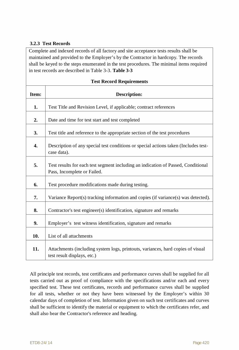
ETD8-24/14 Page 420
3.2.3 Test Records Complete and indexed records of all factory and site acceptance tests results shall be maintained and provided to the Employer’s by the Contractor in hardcopy. The records shall be keyed to the steps enumerated in the test procedures. The minimal items required in test records are described in Table 3-3. Table 3-3
Test Record Requirements
Item:
Description:
1.
Test Title and Revision Level, if applicable; contract references
2.
Date and time for test start and test completed
3.
Test title and reference to the appropriate section of the test procedures
4.
Description of any special test conditions or special actions taken (Includes test-case data).
5.
Test results for each test segment including an indication of Passed, Conditional Pass, Incomplete or Failed.
6.
Test procedure modifications made during testing.
7.
Variance Report(s) tracking information and copies (if variance(s) was detected).
8.
Contractor's test engineer(s) identification, signature and remarks
9.
Employer’s test witness identification, signature and remarks
10.
List of all attachments
11.
Attachments (including system logs, printouts, variances, hard copies of visual test result displays, etc.)
All principle test records, test certificates and performance curves shall be supplied for all tests carried out as proof of compliance with the specifications and/or each and every specified test. These test certificates, records and performance curves shall be supplied for all tests, whether or not they have been witnessed by the Employer’s within 30 calendar days of completion of test. Information given on such test certificates and curves shall be sufficient to identify the material or equipment to which the certificates refer, and shall also bear the Contractor's reference and heading.

ETD8-24/14 Page 421
3.2.4 3.1.4.3Rejection of Elements Any item or component which fails to comply with the requirements of this Specification in any respect, at any stage of manufacture, test, erection or on completion at site may be rejected by the Employer’s either in whole or part as considered necessary.
Material or components with defects of such a nature that do not meet the requirements of the Specification by adjustment or modification shall be replaced by the Contractor at his own expense. After adjustment or modification, the Contractor shall submit the items to the Employer for further inspection and/or tests.
3.3 Type Testing "Type Tests" shall be defined as those tests which are to be carried out to prove the design, process of manufacture and general conformity of the materials to this Specification. Type Testing shall comply with the following:
(a) All equipment being supplied shall conform to type tests as per technical specification.
(b) The Contractor shall submit copies of type test reports conducted during last five years reckoned from the date of opening of tender for all of the Type Tests that are specified in the specifications. These reports may be accepted by the Employer only if they apply to materials and equipment that are essentially identical to those due to be delivered under the Contract and only if test procedures and parameter values are identical to those specified in this specifications carried out at accredited labs and witnessed by third party / customer’s representatives.
(c ) Type Tests should have been certified or performed by reputed laboratories using material and equipment data sheets and test procedures as per this specification. The test procedures shall be formatted as defined in the technical specifications and shall include a complete list of the applicable reference standards.
3.3.1 List of Type Tests The list of required Type tests for FO cabling system as given Appendix Dbelow:.
3.3.2.1 Type Tests for Optical Fibres�� The type tests on DWSM fibres are listed below in table 3-4. The tests specific to the cable
type are listed in subsequent sections. Table 3-4
Type Tests For Optical Fibres
S.No.
Test Name
Acceptance Criteria
Test procedure
1
Attenuation
As per Section-02 of TS
IEC 60793-1-40 Or EIA/TIA 455-78A
2
Attenuation Variation with Wavelength
As per Section-02 of TS
IEC 60793-1-40 Or EIA/TIA 455-78A

ETD8-24/14 Page 422
The type tests on DWSM fibres are listed below in table 3-4. The tests specific to the cable type are listed in subsequent sections.
Table 3-4 Type Tests For Optical Fibres
S.No.
Test Name
Acceptance Criteria
Test procedure
3
Attenuation at Water Peak
As per Section-02 of TS
IEC 60793-1-40 Or EIA/TIA 455-78A
4
Temp. Cycling
(Temp dependence of Attenuation)
IEC 60793-1-52 OrEIA/TIA 455-3A, 2 cycles
5
Attenuation With Bending
(Bend Performance)
IEC 60793-1-47 OrEIA/TIA 455-62A
6
Mode Field dia.
IEC 60793-1-45 OrEIA/TIA 455-
164A/167A/174
7
Chromatic Dispersion
IEC 60793-1-42 OrEIA/TIA 455-
168A/169A/175A
8
Cladding Diameter
IEC 60793-1-20 OrEIA/TIA 455-176
9
Point Discontinuities of attenuation
IEC 60793-1-40 OrEIA/TIA 455-59
10
Core -Clad concentricity error
IEC 60793-1-20 Or EIA/TIA 455-176
11
Fibre Tensile Proof Testing
IEC 60793-1-31 OrEIA/TIA 455-31B
-End Of table-
3.3.2.2 Type Tests for OPGW Cables The type tests on the OPGW cable are listed in table 3-5. Unless specified otherwise in the technical specifications or the referenced standards, the optical attenuation of the specimen, measured during or after the test as applicable, shall not increase by more

ETD8-24/14 Page 423
than0.05 dB/Km.
Table 3-5 Type tests for OPGW Cable
S.No.
Test Name
Test Description
Test Procedure
1
Water Ingress Test
IEEE 1138
Section 4.1.1.1
IEEE 1138, Section 5.1.1.1
(IEC 60794-1-2 Method F5 or EIA/TIA 455-82B) : Test duration : 24 hours
2
Seepage of filling compound
IEEE 1138
Section 4.1.1.2
IEEE 1138
Section 5.1.1.2
(EIA/TIA 455-81B)
Preconditioning period:72 hours. Test duration: 24 hours.
3
Short Circuit Test
IEEE 1138
Section 4.1.1.3
IEEE 1138
Section 5.1.1.3
Fibre attenuation shall be continuously monitored and recorded through a digital data logging system or equivalent means.
A suitable temperature sensor such as thermocouple shall be used to monitor and record the temperature inside the OPGW tube in addition to monitoring & recording the temperatures between the strands and between optical tube and the strand as required by IEEE 1138.
Test shall be conducted with the tension clamps proposed to be supplied. The cable and the clamps shall be visually inspected for mechanical damage and photographed after the test.
Or IEC60794-4-10 / IEC 60794-1-2 (2003) Method H1
Initial temperature
during the test shall be greater than or equal to ambient field temperature.

ETD8-24/14 Page 424
Table 3-5
Type tests for OPGW Cable
S.No.
Test Name
Test Description
Test Procedure 4 Aeolian
Vibration Test
IEEE 1138
Section 4.1.1.4 Or IEC60794-4-10 / IEC 60794-1-2, Method E19
IEEE 1138
Section 5.1.1.4
Fibre attenuation shall be continuously monitored and recorded through a digital data logging system or equivalent means.
The vibration frequency and amplitude shall be monitored and recorded continuously. All fibres of the test cable sample shall be spliced together in serial for attenuation monitoring.
Test shall be conducted with the tension/suspension clamps proposed to be supplied. The cable and the clamps shall be visually inspected for mechanical damage and photographed after the test.
5
Galloping test
IEEE 1138
Section 4.1.1.5
IEEE 1138
Section 5.1.1.5
Test shall be conducted with the tension/suspension clamps proposed to be supplied. The cable and clamps shall be visually inspected for mechanical damage and photographed after the test. All fibres of the test cable sample shall be spliced together in serial for attenuation monitoring.
6
Cable Bend Test
Procedure 2 in IEC 60794-1-2 Method E11
The short-term and long-term bend tests shall be conducted in accordance with Procedure 2 in IEC 60794-1-2 E11 to determine the minimum acceptable radius of bending without any increase in attenuation
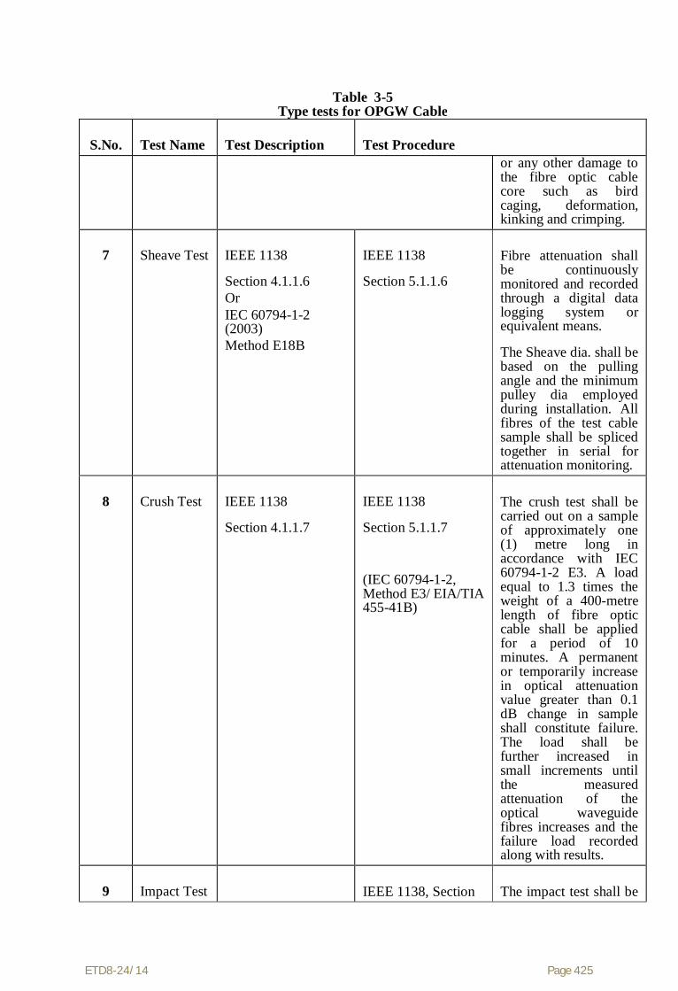
ETD8-24/14 Page 425
Table 3-5
Type tests for OPGW Cable
S.No.
Test Name
Test Description
Test Procedure or any other damage to the fibre optic cable core such as bird caging, deformation, kinking and crimping.
7
Sheave Test
IEEE 1138
Section 4.1.1.6 Or IEC 60794-1-2 (2003) Method E18B
IEEE 1138
Section 5.1.1.6
Fibre attenuation shall be continuously monitored and recorded through a digital data logging system or equivalent means.
The Sheave dia. shall be based on the pulling angle and the minimum pulley dia employed during installation. All fibres of the test cable sample shall be spliced together in serial for attenuation monitoring.
8
Crush Test
IEEE 1138
Section 4.1.1.7
IEEE 1138
Section 5.1.1.7
(IEC 60794-1-2, Method E3/ EIA/TIA 455-41B)
The crush test shall be carried out on a sample of approximately one (1) metre long in accordance with IEC 60794-1-2 E3. A load equal to 1.3 times the weight of a 400-metre length of fibre optic cable shall be applied for a period of 10 minutes. A permanent or temporarily increase in optical attenuation value greater than 0.1 dB change in sample shall constitute failure. The load shall be further increased in small increments until the measured attenuation of the optical waveguide fibres increases and the failure load recorded along with results.
9
Impact Test
IEEE 1138, Section
The impact test shall be

ETD8-24/14 Page 426
Table 3-5
Type tests for OPGW Cable
S.No.
Test Name
Test Description
Test Procedure IEEE 1138
Section 4.1.1.7
5.1.1.7
(IEC 60794-1-2 E4/ EIA/TIA 455-25B)
carried out in accordance with IEC 60794-1-2 E4. Five separate impacts of 0.1-0.3kgm shall be applied. The radius of the intermediate piece shall be the reel drum radius ± 10%. A permanent or temporary increase in optical attenuation value greater than 0.1 dB/km change in sample shall constitute failure.
10
Creep Test
IEEE 1138
Section 4.1.1.8
IEEE 1138
Section 5.1.1.8
As per Aluminium Association Method, the best-fit straight line shall be fitted to the recorded creep data and shall be extrapolated to 25 years. The strain margin of the cable at the end of 25 years shall be calculated. The time when the creep shall achieve the strain margin limits shall also be calculated.
11
Fibre Strain Test
IEEE 1138
Section 4.1.1.9
IEEE 1138
Section 5.1.1.9
12
Strain Margin Test
IEEE 1138
Section 4.1.1.10
IEEE 1138
Section 5.1.1.10
13
Stress strain Test
IEEE 1138
Section 4.1.1.11
IEEE 1138
Section 5.1.1.11
14
Cable Cut-off wavelength Test
IEEE 1138
Section 4.1.1.12
IEEE 1138
Section 5.1.1.12
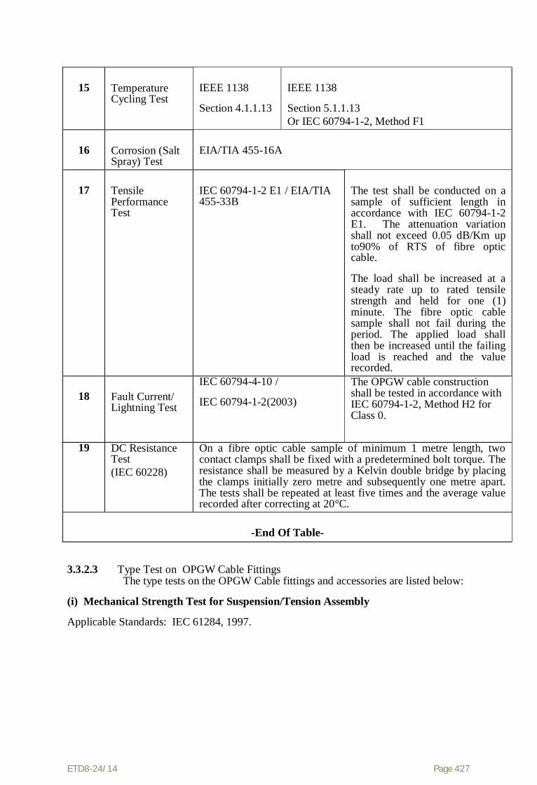
ETD8-24/14 Page 427
15
Temperature Cycling Test
IEEE 1138
Section 4.1.1.13
IEEE 1138
Section 5.1.1.13 Or IEC 60794-1-2, Method F1
16
Corrosion (Salt Spray) Test
EIA/TIA 455-16A
17
Tensile Performance Test
IEC 60794-1-2 E1 / EIA/TIA 455-33B
The test shall be conducted on a sample of sufficient length in accordance with IEC 60794-1-2 E1. The attenuation variation shall not exceed 0.05 dB/Km up to90% of RTS of fibre optic cable.
The load shall be increased at a steady rate up to rated tensile strength and held for one (1) minute. The fibre optic cable sample shall not fail during the period. The applied load shall then be increased until the failing load is reached and the value recorded.
18
Fault Current/ Lightning Test
IEC 60794-4-10 /
IEC 60794-1-2(2003)
The OPGW cable construction shall be tested in accordance with IEC 60794-1-2, Method H2 for Class 0.
19 DC Resistance Test (IEC 60228)
On a fibre optic cable sample of minimum 1 metre length, two contact clamps shall be fixed with a predetermined bolt torque. The resistance shall be measured by a Kelvin double bridge by placing the clamps initially zero metre and subsequently one metre apart. The tests shall be repeated at least five times and the average value recorded after correcting at 20°C.
-End Of Table-
3.3.2.3 Type Test on OPGW Cable Fittings The type tests on the OPGW Cable fittings and accessories are listed below:
(i) Mechanical Strength Test for Suspension/Tension Assembly
Applicable Standards: IEC 61284, 1997.

ETD8-24/14 Page 428
Suspension Assembly
The armour rods /reinforcement rods are assembled on to the approved OPGW using the Installation Instructions to check that the assembly is correctly fitted and is the same that will be carried out during installations.
Part 1:
The suspension assembly shall be increased at a constant rate up to a load equal to 50% of the specified minimum Failure Load increased and held for one minute for the test rig to stabilise. The load shall then be increased at a steady rate to 67% of the minimum Failure Load and held for five minutes. The angle between the cable, the Suspension Assembly and the horizontal shall not exceed 16o. This load shall then be removed in a controlled manner and the Protection Splice disassembled. Examination of all the components shall be made and any evidence of visual deformation shall be documented.
Part 2:
The Suspension clamp shall then be placed in the testing machine. The tensile load shall gradually be increased up shall gradually be increased up to 50% of the specified Minimum Failure Load of the Suspension Assembly and held for one minute for the Test Rig to stabilise and the load shall be further increased at a steady rate until the specified minimum Failure Load is reached and held for one minute. No fracture should occur during this period. The applied load shall then be increased until the failing load is reached and the value shall be documented.
Tension Assembly
The Tension Assembly is correctly fitted and is the same that will be carried out during installations.
Part 1:
The tension assembly (excluding tension clamp) shall be increased at a constant rate up to a load equal to 50% of the specified minimum Failure Load increased at a constant rate and held for one minute for the test rig to stabilise. The load shall then be increased at a steady rate to 67% of the minimum Failure Load and held for five minutes. This load shall then remove in a controlled manner and the Tension Assembly disassembled. Examination of the Tension Dead-End and associated components shall be made and any evidence of visual deformation shall be documented.
Part 2:
The Tension Dead-End and associated components shall then be reassembled and bolts tightened as before. The tensile load shall gradually be increased up shall gradually be increased up to 50% of the specified Minimum Failure Load of the Tension Assembly and held for one minute for the Test Rig to stabilise and the load shall be further increased at a steady rate until the specified minimum Failure Load is reached and held

ETD8-24/14 Page 429
for one minute. No fracture should occur during this period. The applied load shall then be increased until the failing load is reached and the value shall be documented.
Acceptance Criteria for Tension/Suspension Assembly:
- No evidence of binding of the Nuts or Deformation of components at end of Part 1 of Test.
- No evidence of Fracture at the end of one minute at the minimum failure load during Part 2 of the Test.
Any result outside these parameters shall constitute a failure.
(ii) Clamp Slip Strength Test for Suspension Assembly
The suspension assembly shall be vertically suspended by means of a flexible attachment. A suitable length fibre optical cable shall be fixed in the clamps. Once the Suspension Clamp has been assembled, the test rig is tensioned to 1 kN and the position scale on the recorder ‘zeroed’. The test rig is then tensioned to 2.5 kN and the relative positions of the Reinforcing Rods, Armour Rods and Suspension Clamp shall be marked by a suitable means to confirm any slippage after the test has been completed. The relative positions of the helical Armour Rods and associated Reinforcing Rods at each end shall be marked and also 2 mm relative position between clamp body and Armour Rods shall be marked on one side. The load shall be increased to 12 kN at a loading rate of 3 kN/min and held for one minute. At the end of this one minute period, the relative displacement between clamp body and the armour rods shall be observed. If the slippage is 2 mm or above, the test shall be terminated. Otherwise, at the end of one minute the position of the clamp body and 2 mm. relative positions between clamp body and armour rods shall be marked on the other side. After the one minute pause, the load shall be further increased at a loading rate of 3 kN/min, and recording of load and displacement shall continue until either the relative Position displacement between clamp body and armour rods reaches more than 2 mmor the load reaches the maximum slip load of 17 kN. On reaching either of the above values the test is terminated. Visual examination of all paint marks shall be recorded, and a measurement of any displacement recorded in the Table of Results.
Acceptance Criteria:
The Suspension Clamp has passed the Slip Test if the following conditions are met:
No slippage* shall occur at or below the specified minimum slip load.
* Definition of no slippage in accordance with IEC 61284,1997:- Any relative movement less than 2 mm is accepted. The possible couplings or elongations produced by the cable as a result of the test itself are not regarded as slippage.
Slippage shall occur between the specified maximum and minimum slip load of 12 - 17 kN.
There shall be no slippage of the Reinforcing Rods over the cable, and no slippage of the Armour Rods over the Reinforcing Rods.
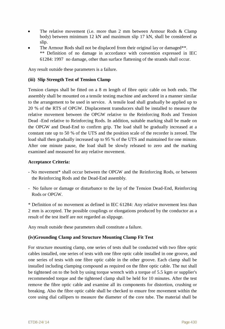
ETD8-24/14 Page 430
The relative movement (i.e. more than 2 mm between Armour Rods & Clamp body) between minimum 12 kN and maximum slip 17 kN, shall be considered as slip.
The Armour Rods shall not be displaced from their original lay or damaged**. ** Definition of no damage in accordance with convention expressed in IEC 61284: 1997 no damage, other than surface flattening of the strands shall occur.
Any result outside these parameters is a failure.
(iii) Slip Strength Test of Tension Clamp
Tension clamps shall be fitted on a 8 m length of fibre optic cable on both ends. The assembly shall be mounted on a tensile testing machine and anchored in a manner similar to the arrangement to be used in service. A tensile load shall gradually be applied up to 20 % of the RTS of OPGW. Displacement transducers shall be installed to measure the relative movement between the OPGW relative to the Reinforcing Rods and Tension Dead -End relative to Reinforcing Rods. In addition, suitable marking shall be made on the OPGW and Dead-End to confirm grip. The load shall be gradually increased at a constant rate up to 50 % of the UTS and the position scale of the recorder is zeroed. The load shall then gradually increased up to 95 % of the UTS and maintained for one minute. After one minute pause, the load shall be slowly released to zero and the marking examined and measured for any relative movement.
Acceptance Criteria:
- No movement* shall occur between the OPGW and the Reinforcing Rods, or between the Reinforcing Rods and the Dead-End assembly.
- No failure or damage or disturbance to the lay of the Tension Dead-End, Reinforcing Rods or OPGW.
* Definition of no movement as defined in IEC 61284: Any relative movement less than 2 mm is accepted. The possible couplings or elongations produced by the conductor as a result of the test itself are not regarded as slippage.
Any result outside these parameters shall constitute a failure.
(iv)Grounding Clamp and Structure Mounting Clamp Fit Test
For structure mounting clamp, one series of tests shall be conducted with two fibre optic cables installed, one series of tests with one fibre optic cable installed in one groove, and one series of tests with one fibre optic cable in the other groove. Each clamp shall be installed including clamping compound as required on the fibre optic cable. The nut shall be tightened on to the bolt by using torque wrench with a torque of 5.5 kgm or supplier's recommended torque and the tightened clamp shall be held for 10 minutes. After the test remove the fibre optic cable and examine all its components for distortion, crushing or breaking. Also the fibre optic cable shall be checked to ensure free movement within the core using dial callipers to measure the diameter of the core tube. The material shall be

ETD8-24/14 Page 431
defined as failed if any visible distortion, crushing, cracking or breaking of the core tube is observed or the fibre optic cable within the core tube is not free to move, or when the diameter of the core tube as measured at any location in the clamped area is more than 0.5 mm larger or smaller of the core diameter as measured outside the clamped area.
(v) Structure Mounting Clamp Strength Test
The clamp and mounting assembly shall be assembled on a vertical 200 mm x 200 mm angle and a short length of fibre optic cable installed. A vertical load of 200 kg shall be applied at the end of the mounting clamp and held for 5 minutes. Subsequently, the load shall be increased to 400 kg and held for 30 seconds. Any visible distortion, slipping or breaking of any component of the mounting clamp or assembly shall constitute failure.
3.3.2.4 Type Test on Vibration Damper
(i) Dynamic Characteristic Test
The damper shall be mounted with its clamp tightened with torque recommended by the manufacturer on shaker table capable of simulating sinusoidal vibrations for Critical Aeolian Vibration frequency band as determined through vibration analysis of undamped OPGW. The damper assembly shall be vibrated vertically with a ±1 mm amplitude from 5 to 15 Hz frequency and beyond 15 Hz at 0.5 mm to determine following characteristics with the help of suitable recording instruments.
(a) Force Vs frequency
(b) Phase angle Vs frequency
(c) Power dissipation Vs frequency
The Force Vs frequency curve shall not show steep peaks at resonance frequencies and deep troughs between the resonance frequencies. The resonance frequencies shall be suitably spread within the Aeolian vibration frequency-band between the lower and upper dangerous frequency limits determined by the vibration analysis of fibre optic cable without dampers.
The above dynamic characteristics test shall be conducted on five dampers. The variations between the samples tested shall conform to the sample test limits.
(ii) Vibration Analysis
The vibration analysis of the fibre optic cable shall be done with and without damper installed on the span. The vibration analysis shall be done on a digital computer using energy balance approach. The following parameters shall be taken into account for the purpose of analysis.

ETD8-24/14 Page 432
(d) The analysis shall be done for single fibre optic cable without armour rods. The tension shall be taken as max Permissible Every Day Tension (20% of UTS), for a span ranging from 100 m to 1100 m.
(e) The self damping factor and flexural stiffness (EI) for fibre optic cable shall be calculated on the basis of experimental results. The details to experimental analysis with these data shall be furnished.
(f) Examine the Aeolian Vibration level of the fibre optic cable with and without vibration damper installed at the recommended location or wind velocity ranging from 0 to 30 Km per hour, predicting amplitude, frequency and vibration energy input.
(g) From vibration analysis of fibre optic cable without damper, antinode vibration amplitude and dynamic strain levels at clamped span extremities as well as antinodes shall be examined and thus lower and upper dangerous frequency limits between which the Aeolian vibration levels exceed the specified limits shall be determined.
(h) From vibration analysis of fibre optic cable with damper(s) installed at the recommended location, the dynamic strain level at the clamped span extremities, damper attachment point and the antinodes on the fibre optic cable shall be determined. In addition to above damper clamp vibration amplitude and antinodes vibration amplitudes shall also be examined.
The dynamic strain levels at damper attachment point, clamped span extremities and antinodes shall not exceed the specified limits. The damper clamp vibration amplitude shall not be more than that of the specified fatigue limits.
3.3.2.4.1 Vibration Damper Clamp Slip and Fatigue Tests
(i) Test Set Up
The clamp slip and fatigue tests shall be conducted on a laboratory set up with a minimum effective span length of 30m. The fibre optic cable shall be tensioned at 15 kN and shall not be equipped with protective armour rods at any point.
Constant tension shall be maintained within the span by means of lever arm arrangement. After the fibre optic cable has been tensioned, clamps shall be installed to support the fibre optic cable at both ends and thus influence of connecting hardware fittings are eliminated from the free span. The clamps shall not be used for holding the tension on the fibre optic cable. There shall be no loose parts, such as suspension clamps, U bolts, on the test span supported between clamps mentioned above. The span shall be equipped with vibration inducing equipment suitable for producing steady standing vibration. The inducing equipment shall have facilities for step less speed control as well as step less

ETD8-24/14 Page 433
amplitude arrangement. Equipment shall be available for measuring the frequency, cumulative number of cycles and amplitude of vibration at any point along the span.
(ii) Clamp Slip Test
The vibration damper shall be installed on the test span. The damper clamp, after tightening with the manufacturer's specified tightening torque, when subjected to a longitudinal pull of 2.5 kN parallel to the axis of fibre optic cable for a minimum duration of one minute shall not slip, i.e., the permanent displacement between fibre optic cable and clamp measured after removal of the load shall not exceed 1.0 mm. The load shall be further increased until the clamp starts slipping. The load at which the clamp slips shall not be more than 5 kN.
(iii) Fatigue Test
The vibration damper shall be installed on the test span with the manufacturer's specified tightening torque. It shall be ensured that the damper shall be kept minimum three loops away from the shaker to eliminate stray signals influencing damper movement.
The damper shall then be vibrated at the highest resonant frequency of each damper mass. For dampers involving torsional resonant frequencies, tests shall be done at torsional modes also in addition to the highest resonant frequencies at vertical modes. The resonance frequency shall be identified as the frequency at which each damper mass vibrates with the maximum amplitude on itself. The amplitude of vibration of the damper clamp shall be maintained not less than ±25/f mm where f is the frequency in Hz.
The test shall be conducted for minimum ten million cycles at each resonant frequency mentioned above. During the test, if resonance shift is observed, the test frequency shall be tuned to the new resonant frequency.
The clamp slip test as mentioned herein above shall be repeated after fatigue tests without retorquing or adjusting the damper clamp, and the clamp shall withstand a minimum load equal to 80% of the slip strength for a minimum duration of one minute.
After the above tests, the damper shall be removed from fibre optic cable and subjected to dynamic characteristics test. There shall not be any major deterioration in the characteristics of the damper. The damper then shall be cut open and inspected. There shall not be any broken, loose, or damaged part. There shall not be significant deterioration or wear of the damper. The fibre optic cable under clamp shall also be free from any damage.
For purposes of acceptance, the following criteria shall be applied:
(i) There shall not be any frequency shift by more than ±2 Hz for frequencies lower than 15 Hz and ±3 Hz for frequencies higher than 15 Hz.

ETD8-24/14 Page 434
(j) The force response curve shall generally lie within guaranteed % variation in reactance after fatigue test in comparison with that before fatigue test by they Supplier.
(k) The power dissipation of the damper shall not be less than guaranteed % variation in power dissipation before fatigue test by the Supplier. However, it shall not be less than minimum power dissipation which shall be governed by lower limits of reactance and phase angle indicated in the envelope.
3.3.2.5 Type Tests for Splice Enclosures (Joint Box)
Following Type tests shall be demonstrated on the Splice Enclosure(s) (Splice Enclosure/Box) . For certain tests, lengths of the fibre optic cable shall be installed in the splice box, and the fibres must be spliced and looped in order to simulate conditions of use. The attenuation of the fibres shall be measured, during certain tests, by relevant Fibre Optic Test Procedures (EIA/TIA 455 or IEC 60794-1 procedures).
(i) Temperature Cycling Test
FO cable is installed in the splice enclosure and optical fibres spliced and looped. The box must be subjected to 5 cycles of temperature variations of -40C to +65C with a dwell time of at least 2 hours on each extreme.
Fibre loop attenuation shall be measured in accordance with EIA 455-20/ IEC 60794-1-C10. The variation in attenuation shall be less than ±0.05dB. The final humidity level, inside the box, shall not exceed the initial level, at the closing of the box.
(ii) Humid Heat test
The sealed splice enclosure, with fibres spliced and looped inside, must be subjected to a temperature of +55C ±2C with a relative humidity rate of between 90% and 95% for 5 days. The attenuation variation of the fibres during the duration of the test shall be less than ±0.05dB, and the internal humidity rate measured, less than 2% .
(iii) Rain Withstand Test / Water Immersion test
The splice enclosure with optical fibres cable installed and fibres spliced fixed, shall be subjected to 24 hours of simulated rain in accordance with IEC 60060 testing requirements. No water seepage or moisture shall be detected in the splice enclosure. The attenuation variation of the fibres after the test shall be less than ±0.05dB.
(iv) Vibration Test
The splice enclosure, with fibres united inside, shall be subjected to vibrations on two axes with a frequency scanning of 5 to 50 Hz. The amplitude of the vibrations shall be constant at 0.450mm, peak to peak, for 2 hours, for each of the vibrations' axes. The variation in attenuation, of the fibres, shall be less than ±0.05dB. The splice enclosure

ETD8-24/14 Page 435
shall be examined for any defects or deformation. There shall be no loosening or visible damage of the FO cable at the entry point.
(v) Bending and Torsion test
The splice enclosure, with fibres spliced inside, shall be firmly held in place and be subjected to the following sequence of mechanical stresses on the cable:
a) 3 torsion cycles of ±180 shall be exercised on the cable. Each cycle shall be less than one minute.
b) 3 flexure cycles of the cable, of ±180 with one cycle less than one minute.
The variation in the attenuation, of the fibres, shall be less than ±0.05dB. The cables connection ring shall remain securely fixed to the box with the connection maintained firmly. No defects/fissures shall be noted on the joint ring or on the splice enclosure
(vi)Tensile test
The splice enclosure with cable fixed to the boxes shall be subjected to a minimum tension of 448 N for a period of two minutes. No fissure shall be noted in the connections or on the box.
(vii) Drop Test
With 2 lengths of 10 metres of cable fixed to the box, it shall be dropped five times from a height of 11 metres. There shall be no fissure, at all, of the box, and the connections shall remain tight. The test shall be carried out in accordance with procedure described in IEC 60068-2-32.
3.3.2.6 Type Tests for Fibre Optic Approach Cable
The type tests to be conducted on the Fibre Optic Approach cable are listed in table -3-6:Type Tests for Fibre Optic Approach Cable. Unless specified otherwise in the technical specifications or the referenced standards, the optical attenuation of the specimen, measured during or after the test as applicable, shall not increase by more than 0.05 dB/Km.
Table 3-6:
TypeTests Fibre Optic Approach Cable
S.N.
Test Name
Test Procedure
1
Water Ingress Test
(IEC 60794-1-F5 /
EIA 455-82B) Test duration : 24 hours
2
Seepage of filling compound
(EIA 455-81A) Preconditioning : 72 hours,

ETD8-24/14 Page 436
Table 3-6:
TypeTests Fibre Optic Approach Cable
S.N.
Test Name
Test Procedure Test duration : 24 hours.
3
Crush Test
(IEC 60794-1-E3/ EIA 455-41)
4
Impact Test
(IEC-60794-1-E4/ EIA 455-25A)
5
Stress strain Test
(EIA 455-33A)
6
Cable Cut-off wavelength Test
(EIA 455-170)
7
Temperature Cycling Test
(IEC60794-1-F1/EIA-455-3A) – 2 cycles
-End Of Table-
3.3.2.6.1 Impact Test The Impact test shall be carried out in accordance with IEC:60794-1-E4. Five separate impacts of 2.0 kg shall be applied at different locations. The radius of the intermediate piece shall be the reel drum radius ± 10%. A permanent or temporary increase in optical attenuation value greater than 0.05 dB/km shall constitute failure.
3.4 Factory Acceptance Tests Factory acceptance tests shall be conducted on randomly selected Fibre Optic cable & associated accessories to be supplied. Factory acceptance testing shall be carried out on OPGW cable, hardware fittings & accessories and splice enclosures etc. Material shall not be shipped to the Employer until required factory tests are completed satisfactorily, all variances are resolved, full test documentation has been delivered to theEmployer, and the Employer has issued Clearance Certificate. Successful completion of the factory tests and the Employer approval to ship shall in no way constitute final acceptance of the system or any portion thereof. These tests shall be carried out in the presence of the Employer’s authorised representatives unless waival for witnessing by Employer’s representatives is intimated to the contractor. The factory acceptance test shall demonstrate the technical characteristics of the Fibre Optic cable & associated accessories in relation to this specifications and approved drawings and documents. A list of factory acceptance tests for OPGW, hardware fittings & accessories are given in the subsequent clauses. This list of factory acceptance tests shall be supplemented by the Contractor's standard FAT testing program.

ETD8-24/14 Page 437
The factory acceptance tests for the splice enclosures and other items shall be proposed by the Contractor in accordance with technical specifications and Contractor's (including Sub-Contractor's /supplier's) standard FAT testing program. For Test equipment, FAT tests shall include supply of proper calibration certificates, demonstration of satisfactory performance, evidence of correct equipment configuration and manufacturer’s final inspection certificate/ report.
3.4.1 Sampling for FAT From each batch of material presented by the Contractor for Factory acceptance testing, the Employer shall select random sample(s) to be tested for acceptance. Unless otherwise agreed, all required FAT tests in the approved FAT procedures, shall be performed on all samples. The Sampling rate for the Factory acceptance tests shall be 10% of the batch size (minimum 1). The Physical verification shall be carried out on 100% of the offered quantities as per approved procedure. In case any of the selected samples fail, the failed sample is rejected and additional 20% samples shall be selected randomly and tested. In case any sample from the additional 20% also fails the entire batch may be rejected.
For the FO cable hardware fittings & accessories, the minimum sampling rate, and batch acceptance criteria shall be as defined in IS 2486.
3.4.2 Production Testing Production testing shall mean those tests which are to be carried out during the process of production by the Contractor to ensure the desired quality of end product to be supplied by him. The production tests to be carried out at each stage of production shall be based on the Contractor’s standard quality assurance procedures. The production tests to be carried out shall be listed in the Manufacturing Quality Plan (MQP), along with information such as sampling frequency, applicable standards, acceptance criteria etc.
The production tests would normally not be witnessed by the Employer. However, the Employer reserves the right to do so or inspect the production testing records in accordance with Inspection rights specified for this contract.
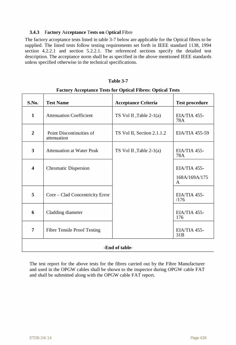
ETD8-24/14 Page 438
3.4.3 Factory Acceptance Tests on Optical Fibre The factory acceptance tests listed in table 3-7 below are applicable for the Optical fibres to be supplied. The listed tests follow testing requirements set forth in IEEE standard 1138, 1994 section 4.2.2.1 and section 5.2.2.1. The referenced sections specify the detailed test description. The acceptance norm shall be as specified in the above mentioned IEEE standards unless specified otherwise in the technical specifications.
Table 3-7
Factory Acceptance Tests for Optical Fibres: Optical Tests
S.No.
Test Name
Acceptance Criteria
Test procedure
1
Attenuation Coefficient
TS Vol II ,Table 2-1(a)
EIA/TIA 455- 78A
2
Point Discontinuities of attenuation
TS Vol II, Section 2.1.1.2
EIA/TIA 455-59
3
Attenuation at Water Peak
TS Vol II ,Table 2-1(a)
EIA/TIA 455- 78A
4
Chromatic Dispersion
EIA/TIA 455-
168A/169A/175A
5
Core – Clad Concentricity Error
EIA/TIA 455-/176
6
Cladding diameter
EIA/TIA 455-176
7
Fibre Tensile Proof Testing
EIA/TIA 455-31B
-End of table-
The test report for the above tests for the fibres carried out by the Fibre Manufacturer and used in the OPGW cables shall be shown to the inspector during OPGW cable FAT and shall be submitted along with the OPGW cable FAT report.
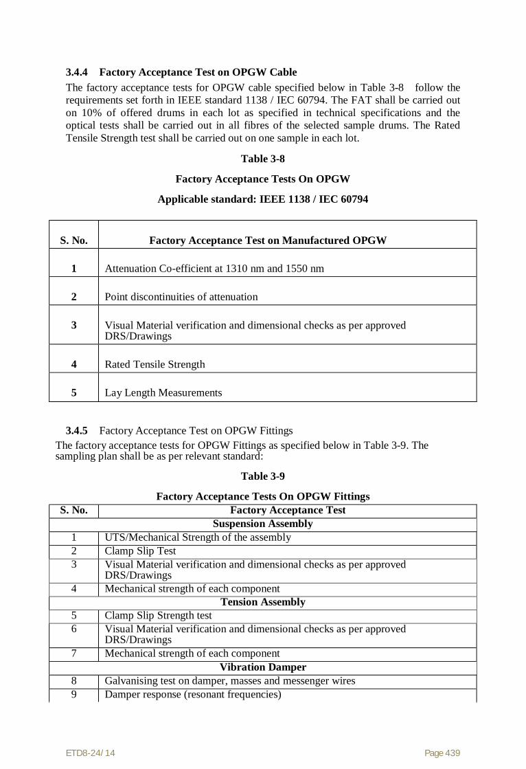
ETD8-24/14 Page 439
3.4.4 Factory Acceptance Test on OPGW Cable The factory acceptance tests for OPGW cable specified below in Table 3-8 follow the requirements set forth in IEEE standard 1138 / IEC 60794. The FAT shall be carried out on 10% of offered drums in each lot as specified in technical specifications and the optical tests shall be carried out in all fibres of the selected sample drums. The Rated Tensile Strength test shall be carried out on one sample in each lot.
Table 3-8
Factory Acceptance Tests On OPGW
Applicable standard: IEEE 1138 / IEC 60794
S. No.
Factory Acceptance Test on Manufactured OPGW
1
Attenuation Co-efficient at 1310 nm and 1550 nm
2
Point discontinuities of attenuation
3
Visual Material verification and dimensional checks as per approved DRS/Drawings
4
Rated Tensile Strength
5
Lay Length Measurements
3.4.5 Factory Acceptance Test on OPGW Fittings The factory acceptance tests for OPGW Fittings as specified below in Table 3-9. The sampling plan shall be as per relevant standard:
Table 3-9
Factory Acceptance Tests On OPGW Fittings S. No. Factory Acceptance Test
Suspension Assembly 1 UTS/Mechanical Strength of the assembly 2 Clamp Slip Test 3 Visual Material verification and dimensional checks as per approved
DRS/Drawings 4 Mechanical strength of each component
Tension Assembly 5 Clamp Slip Strength test 6 Visual Material verification and dimensional checks as per approved
DRS/Drawings 7 Mechanical strength of each component
Vibration Damper 8 Galvanising test on damper, masses and messenger wires 9 Damper response (resonant frequencies)

ETD8-24/14 Page 440
The factory acceptance tests for OPGW Fittings as specified below in Table 3-9. The sampling plan shall be as per relevant standard:
Table 3-9
Factory Acceptance Tests On OPGW Fittings S. No. Factory Acceptance Test
10 Clamp Slip test 11 Strength of messenger wires 12 Mass pull off test 13 Visual Material verification and dimensional checks as per approved
DRS/Drawings Structure Mounting Clamp
14 Clamp fit test 15 Clamp Strength test 16 Visual Material verification and dimensional checks as per approved
DRS/Drawings End of Table
3.4.6 Factory Acceptance Test on Approach Cable The factory acceptance tests for Approach Cable specified below in Table 3-10:
Table 3-10 Factory Acceptance Tests On Approach Cable S. No. Factory Acceptance Test
1 Attenuation Co-efficient at 1310 nm and 1550 nm 2 Point discontinuities of attenuation 3 Visual Material verification and dimensional checks as per approved
DRS/Drawings
3.4.7 Factory Acceptance Test on Splice Enclosure (Joint Box) The factory acceptance tests for Splice Enclosures as specified below in Table 3-11:
Table 3-11
Factory Acceptance Tests on Splice Enclosures S. No. Factory Acceptance Test
1 Visual check of Quantities and Specific Component Number for each component of Splice Enclosure and dimensional checks against the approved drawings.
3.4.8 Factory Acceptance Test on FODP The factory acceptance tests for FODP as specified below in Table 3-12:
Table 3-12
Factory Acceptance Tests on FODP
S. No.
Factory Acceptance Test
1
Visual check of Quantities and Specific Component Number for each component of FODP and dimensional checks against the approved drawings.

ETD8-24/14 Page 441
3.4.9 Factory Acceptance Test on Test Equipment As per technical specification and approved DRS/Documents.
3.5 Site Acceptance Tests(SAT) The Contractor shall be responsible for the submission of all equipments including test equipments supplied in this contract for site tests and inspection as required by the Employer. All equipment shall be tested on site under the conditions in which it will normally operate.
The tests shall be exhaustive and shall demonstrate that the overall performance of the contract works satisfies every requirement specified. A minimum Site Acceptance Testing requirement is outlined in following section. This testing shall be supplemented by the Contractor's standard installation testing program, which shall be in accordance with his quality plan(s).
During the course of installation, the Employer shall have full access for inspection and verification of the progress of the work and for checking workmanship and accuracy, as may be required. On completion of the work prior to commissioning, all equipment shall be tested to the satisfaction of the Employer to demonstrate that it is entirely suitable for commercial operation.
3.5.1 Phases of Site Acceptance Testing The tests, checks, adjustments etc conducted by the Contractor prior to offering for SAT shall be called Pre-SAT activities. The Pre-SAT activities shall be described in the installation manuals and Field Quality Plan documents.
3.5.2 Minimum Site Acceptance Testing Requirement for FO Cabling Site Acceptance Testing (SAT) shall comprise of following:
(a) Pre-installation of OPGW
- Attenuation & length measurement of each OPGW drum using OTDR
(b) Post-installationof OPGW before Splicing
- Measurement of attenuation with OTDR
(c)Post-installation of OPGW after Splicing
- Measurement of bi-directional average attenuation with OTDR
Prior to installation, every spooled fibre optic cable segment shall be tested for compliance with the Pre-shipment data previously received from the manufacturer. This requirement will preclude the installation of out of specification cable segments that may have been damaged during shipment.

ETD8-24/14 Page 442
“Sag and tension of OPGW shall be as per approved sag-tension chart and during installation, sag and tension of OPGW shall be documented. During the installation, spliced cable segments shall be tested and documented. Upon completion of a continuous cable path of OPGW, all fibres within the cable path shall be demonstrated for acceptance of the cable path Fibre Optic cable site testing minimum requirements are provided in Table 3-13(a) through 3-13(c).
Table 3-13(a):
Fibre Optic Cable Pre-Installation Testing
Item:
Description:
1.
Physical Inspection of the cable assembly for damage
2.
Optical fibre continuity and fibre attenuation with OTDR at 1550 nm
3.
OPGW cable length measurement using OTDR
Table 3-13(b):
Fibre Optic Cable Splice Testing
Item:
Description:
1.
Per splice bi-directional average attenuation with OTDR
2.
Physical inspection of splice box/enclosure for proper fibre routing techniques
3.
Physical inspection of sealing techniques, weatherproofing, etc. Table 3-13(c):
Fibre Optic Cable Commissioning Testing
Item:
Description:
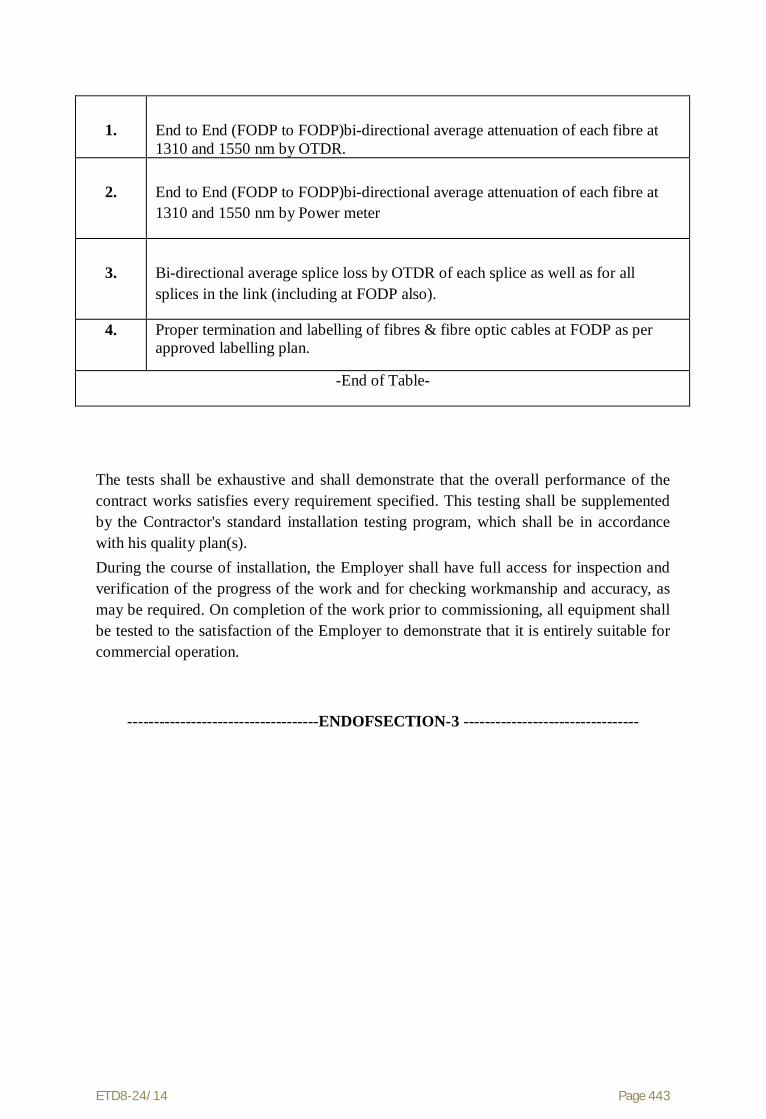
ETD8-24/14 Page 443
1.
End to End (FODP to FODP)bi-directional average attenuation of each fibre at 1310 and 1550 nm by OTDR.
2.
End to End (FODP to FODP)bi-directional average attenuation of each fibre at 1310 and 1550 nm by Power meter
3.
Bi-directional average splice loss by OTDR of each splice as well as for all splices in the link (including at FODP also).
4. Proper termination and labelling of fibres & fibre optic cables at FODP as per approved labelling plan.
-End of Table-
The tests shall be exhaustive and shall demonstrate that the overall performance of the contract works satisfies every requirement specified. This testing shall be supplemented by the Contractor's standard installation testing program, which shall be in accordance with his quality plan(s). During the course of installation, the Employer shall have full access for inspection and verification of the progress of the work and for checking workmanship and accuracy, as may be required. On completion of the work prior to commissioning, all equipment shall be tested to the satisfaction of the Employer to demonstrate that it is entirely suitable for commercial operation.
------------------------------------ENDOFSECTION-3 ---------------------------------

ETD8-24/14 Page 444
Section-4
Training & Support Services

ETD8-24/14 Page 445
Section - 4 Training & Support Services
This section shall be read with clause no. 2.15 of General Requirement of Specification (Commercial) Part-I, Section-2.
4.1 Training The Contractor shall impart training for the Installation, Supervision &
Maintenance which shall enable the trainees to effectively supervise the fibre optic cable installation work from an Employer perspective, particularly with respect to installation quality checks and safety procedures. The training shall cover FO cable handling techniques, stringing and installation, jointing & splicing, OTDR use and OTDR trace analysis, operation, preventive maintenance, troubleshooting procedures, corrective maintenance, and expansion procedures. No extra charges shall be paid to the Contractor for such training.
It shall also cover an appreciation of restorative procedures required after any likely cable failure such as cable breaks due to storms or falling trees, installation hardware failures or misalignments.
Installation training shall be predominantly hands-on training courses provided for a group of persons. The intent of this training is to enable Employer to undertake maintenance & restoration work in case of cable breaks or other such failures.
4.1.2 Fibre Optic cable Installation and Maintenance Training There shall be installation & maintenance training for OPGW cable & associated items.
The installation & maintenance trainings shall enable the Employer to be self-sufficient in preventive & restorative maintenance of the OPGW cable & associated items purchased by the Employer. The training courses shall cover OPGW cable & associated items installation, testing & commissioning, preventive maintenance, diagnostic tools and troubleshooting procedures, corrective maintenance for OPGW cable. The courses shall provide theoretical background and extensive hands on experience.
4.2 Support Services Throughout design, implementation, factory testing, and field installation and testing, the Contractor shall supply consulting assistance, as required by the Employer for site preparation, field installation, and other areas where technical support may be required.
The Contractor shall be responsible for minor facility renovation and maintenance of the supplied system up to and including successful completion of the Site Acceptance Test.
4.3 Spare Parts and Test Equipment The spare parts and test equipment shall be provided as described below:

ETD8-24/14 Page 446
4.3.1Recommended Spare Parts The bidder shall propose a comprehensive spare parts strategy. , suitable to support the specified level of system availability. The intent of the spare parts strategy is to ensure a readiness against unforeseen cabling system breakdowns, and to carry out replacement maintenance of susceptible or failed components. Consistent with the proposed spare parts strategy, the bidder shall provide a list of “Recommended Spare Parts”, which may be required over and above the spares listed in Mandatory Spare parts list (Section 4.3.1 above), to support the OPGW cable & associated items during a one-year period. This list of spares shall be called the "Recommended Spare Parts List".
The Contractor shall provide in their bid, additionally recommended test equipment list necessary to support specified system outage requirement. These lists shall include all relevant technical descriptions and recommended minimum quantities and maintenance concept. The additionally recommended test equipment may be included in the final scope of supply and the price thereof shall not be considered for evaluation.

ETD8-24/14 Page 447
Section-5
Documentation and Deliverables
(To be submitted with the proposal of vendor approval by the successful tender after placement
of order)
ETD8-24/14 Page 448
Section 5 Documentation and Deliverables
This section describes the documentation requirements and provides a list of deliverable that the Contractor shall provide to the Employer. Complete documentation necessary for the operation and maintenance of the fibre optic cabling system is required. All the documentation shall be provided in hard copy and also on CD-ROMs in full compliance with the specification. Conditions pertaining to Document Review and Approval Rights and Document Submission Scheduling are specified in this section.
The documentation shall include the following:
(a) Detailed list of the deliverables (b) Description of the products (c) Technical particulars (d) Installation manuals (e) Maintenance manuals (f) Quality assurance manuals, Manufacturing Quality Plan (MQP) & Field Quality Plan (FQP)
(g) Tests documentation
5.1 System Documentation A detailed documentation plan and document submission schedule shall be prepared and submitted for approval. The guidelines specified in table 5-1 & table 5-2 shall be followed.
5.2 Supplementary Documentation While performing maintenance during the warranty period, the Employer determines that additional information is required to perform the maintenance function, the Contractor and/or its subcontractors shall provide the specific supplemental information necessary to perform the maintenance function. This information shall be documented in a form suitable for incorporation into the appropriate maintenance document.
5.3 Test Documentation The Contractor shall provide documentation for all Type tests, Factory Acceptance tests and site tests (SAT).
The test documentation shall include the following:
a. Type test Documents (Procedures & Reports)
b. Factory Acceptance Test Documents (Procedures & Reports)
c. Site Acceptance Test Documents (Procedures & Reports)
5.4 Drawings All drawings submitted by the Contractor including those submitted at the time of bid shall be in sufficient detail to indicate the type, size, arrangement, dimensions, material description, Bill of Materials, weight of each component, break-up for packing and shipment, shipping arrangement required, the dimensions required for installation and any other information specifically requested in the Specifications.

ETD8-24/14 Page 449
Each drawing submitted by the Contractor shall be clearly marked with the Employer name, the unit designation, the specification title, the specification number and the name of the Project. All titles, notes, markings and writings on the drawing shall be in English. All the dimensions should be to the scale and in metric units. The drawing revision level/ issue no, issue date shall be marked on each drawing and the drawing shall carry issue history information and appropriate signatures (eg: originator, checker and approving authority).
5.5 Drawing and Document Approval Procedure The drawings/documents submitted by the Contractor shall be reviewed by the Employer as far as practicable within stipulated duration and shall be modified by the Contractor if any modifications and/or corrections are required by the Employer in compliance with the Specifications. The Contractor shall incorporate such modifications and/or corrections and submit the final drawings for approval. Any delays arising out of failure by the Contractor to rectify the drawings in good time shall not alter the contract completions date.
The drawings/documents submitted for approval to the Employer shall be in quadruplicate. One print of such drawings shall be returned to the Contractor by the Employer marked with one of the categories as listed below:-
Category Inference
Cat I Approved/Released for implementation.
Cat II Approved/Released for implementation subject to incorporation of comments. Revised drawing required.
Cat III To be resubmitted for approval after incorporating comments.
Cat IV For information and record.
The approval of the drawing/document conveyed vide above marked copy shall neither relieve the Contractor of its contractual obligations and its responsibilities towards weights, qualities, design details, assembly fits, performance particulars and conformity of supplies with the Indian Statutory Laws as may be applicable, nor shall it limit Employer’s and/or Employer’s right under the contract.
Depending upon the category of approval the Contractor shall resubmit the drawings/documents for review by Employer after incorporating all corrections.
Further work by the Contractor shall be strictly in accordance with the Cat-I, Cat-II or Cat-IV approved drawings and no deviation shall be permitted without the written approval of the Employer.
All manufacturing and fabrication work in connection with the equipment/material prior to the approval of the drawings shall be at the Contractor’s risk. The Contractor may make any changes in the design which are necessary to make the equipment/material conform to the provisions and intent of the Contract and such changes will again be subject to approval by the Employer. Approval of Contractor’s drawing or work by the Employer shall not relieve the Contractor of any of his responsibilities and liabilities under the Contract.
5.6 Final Documentation Final documentation shall consist of all the documents approved in Cat I and Cat IV. The documents will be used by the Employer personnel for operating and maintaining the equipment after acceptance.

ETD8-24/14 Page 450
Until acceptance of the equipment by the Employer, the Contractor shall be responsible for supplying documentation revisions or changes necessitated by inaccuracies, installation requirements, omissions determined by usage, and design or production alterations to the equipment. All changes shall be issued in the form of replacements for the affected drawings, diagrams, charts, graphs, tables, lists, and pages in the various documentation such that all documentation describes the equipment "as delivered".
For all the documents listed in Table 5.1 (except Type, FAT & SAT related), five(5) sets of the final approved documentation shall be provided for the engineering office of the Employer in CD-ROM and two (2) sets in hard copy.
All final Contractor-supplied documentation shall be easily reproducible by the Employer.
Table 5-1: Documentation Plan
S. No
Document
Applicable Equipments/Item
Brief Description
Approval Category
1. Documentation Plan and Schedule
This document shall contain the list of all documents to be submitted for approval and their submission/approval schedule.
Cat - I
2. Survey guidelines & formats
As per technical specifications.
Cat - I
3. Data Requirement Sheets (DRS) and
Guaranteed Technical Parameters & Drawings
For each and every item to be supplied including fibre, OPGW cable, approach cable, joint box, FODP, All FO cable Hardware & fittings (suspension clamp assembly, tension clamp assembly, vibration damper etc.), test equipment.
These document(s) shall describe all the technical parameters of the item being offered. The formats for some items provided in the appendices shall be used, which may be expanded as required. The DRS shall be submitted for all items. The DRS shall be supported by technical brochures/product manuals.
Cat - I (for DRS) & Cat – IV (for brochure)
4. Sag tension charts
For OPGW cable Shall accompany the DRS document
Cat - I
5. Previous For all items for Shall be complete in all respect Acceptanc

ETD8-24/14 Page 451
Table 5-1: Documentation Plan
S. No
Document
Applicable Equipments/Item
Brief Description
Approval Category
type test reports
which type testing is required. (fibre, OPGW cables, Hardware & fittings for OPGW cable, approach cable, joint box, )
including all test graphs, curves, calculations, photographs etc.
e Letter
6. Manufacturing Quality Plan
For all items to be supplied
Refer technical specifications. Cat- IV
7.
Survey reports & engineering analysis
For FO cable link Line wise survey reports, indicating tower schedules, drum schedules, crossing details, hardware & fitting requirements etc. Shall include linewise sag-tension charts and other engineering analysis etc.
Cat- I (for Drum Schedule) and Cat-IV for other detailed report
8. Link and survey reports & engineering analysis
For each Fibre Optic link and site
Link wise survey reports as per specifications, link calculations etc.
Cat- I
9. Numbering, Marking, labeling Document
As applicable.
Must include numbering, marking, labeling and naming conventions for channels, cables, connectors, sub racks, cubicles etc
Cat- I
10.
Bill of Quantities
For each item and each line
Line wise survey reports, indicating tower schedules, drum schedules, crossing details, hardware & fitting requirements etc. Shall include line wise sag-tension charts and other engineering analysis such as tower strengthening analysis etc.
Cat- I
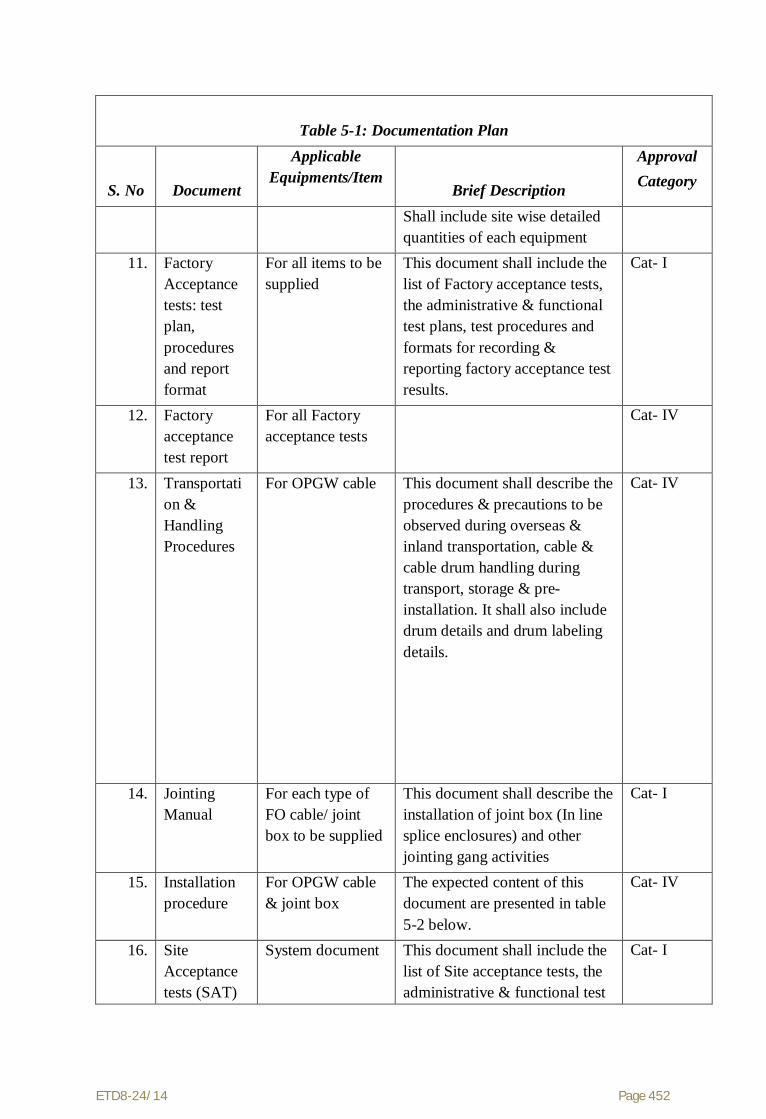
ETD8-24/14 Page 452
Table 5-1: Documentation Plan
S. No
Document
Applicable Equipments/Item
Brief Description
Approval Category
Shall include site wise detailed quantities of each equipment
11. Factory Acceptance tests: test plan, procedures and report format
For all items to be supplied
This document shall include the list of Factory acceptance tests, the administrative & functional test plans, test procedures and formats for recording & reporting factory acceptance test results.
Cat- I
12. Factory acceptance test report
For all Factory acceptance tests
Cat- IV
13. Transportation & Handling Procedures
For OPGW cable This document shall describe the procedures & precautions to be observed during overseas & inland transportation, cable & cable drum handling during transport, storage & pre-installation. It shall also include drum details and drum labeling details.
Cat- IV
14. Jointing Manual
For each type of FO cable/ joint box to be supplied
This document shall describe the installation of joint box (In line splice enclosures) and other jointing gang activities
Cat- I
15. Installation procedure
For OPGW cable & joint box
The expected content of this document are presented in table 5-2 below.
Cat- IV
16. Site Acceptance tests (SAT)
System document This document shall include the list of Site acceptance tests, the administrative & functional test
Cat- I

ETD8-24/14 Page 453
Table 5-1: Documentation Plan
S. No
Document
Applicable Equipments/Item
Brief Description
Approval Category
test plan, procedures and report format
plans, test procedures and formats for recording & reporting site acceptance test results.
17. Field Quality Plan
One Document with multiple subdocuments if required
Field Quality Plan shall describe the quality control to be exercised during the field activities. This document can include the following information: (a.) The list of performance & safety checks applied to installation equipment, tools & tackles, checks, check on physical health & training records of installation crew etc. (b.) The list of Site Acceptance tests (including statement of acceptance criteria). The inclusion of list of site acceptance tests in FQP is analogous to the inclusion of list of FAT in the MQP. The formats for recording & reporting Site acceptance tests can also be reproduced.
Cat- I
18. Approach cable Installation document - General
Approach Cable This document shall describe the general approaches to be adopted for installation of Approach cables, for example the document shall try to answer questions such as whether cable trenches or cable raceways shall be used? Or whether any conduits/ ducts will be used, if so, of what type? Etc.
Cat - I

ETD8-24/14 Page 454
Table 5-1: Documentation Plan
S. No
Document
Applicable Equipments/Item
Brief Description
Approval Category
This document shall describe all allowable alternative installation methodologies, such that the actual implementation at a particular site shall
19. Approach Cable & FODP layout document – site wise
For each site To describe the layout of approach cable at each site and the floor plan of the FODP.
Cat - I
20.
Site test records as per approved SAT procedures
Per Link and per Location
*
* To be reviewed & approved by the Site
Table 5-2: Expected Contents & Structure of FO Cable / Equipment Installation Manual
1.
Installation procedure
Description of activities of installation gangs: Preparation & Setting up, Stringing, sagging, attaching hardware, attaching down lead clamps & cable routing on the tower, securing cable ends (for protection before work by jointing gang). Precautions for preventing cable damage shall be highlighted.
2.
Safety Instructions
Instructions & procedures related to ensuring installation crew safety: personnel grounding & safety, installation equipment safety, Safety for power system & environment (viz preventing accidental tripping, precaution for railway crossings etc)
3.
Description of Installation Equipment
Sketches, drawings, photographs, safe working ratings of installation equipment, tools & tackles etc., handling instructions & precautions.
4.
Cable routing
Illustrations of the positions of tower attachment clamps (down lead clamps), routing of FO cable on the tower, service loop(s), joint box position.

ETD8-24/14 Page 455
Table 5-2: Expected Contents & Structure of FO Cable / Equipment Installation Manual
5.
References
References to other related documents covering the installation, jointing & testing, like: SAT administrative & functional test plans & test procedures, Jointing Procedures, Field Quality Plan & Field Quality Audit, Storage & Handling Instructions, FO cable & hardware drawings, technical parameters, DRS etc. Employer & Statutory safety rules, safety manuals, standards, codes of practices etc.

ETD8-24/14 Page 456
Appendix- A
Data Requirement Sheets (DRS)
(The DRS forms have been included for the major items; however, the DRS for each item along with sufficient details shall be submitted.)

ETD8-24/14 Page 457
Appendix A
Data Requirement Sheets
The following sets of Data Requirement Sheets are required to be filled up by the bidders
to aid in the evaluation process. The response shall be brief and to the point and shall be
supported by the printed product description and other literature. The same DRS format
duly filled and the relevant drawings shall also be submitted during the detailed
engineering along with the relevant technical brochures.

ETD8-24/14 Page 458
DRS Form-1
Data Requirements Sheets for OVERHEAD FIBRE OPTIC CABLE
OPTICAL GROUND WIRE (OPGW):
Manufacturer: _______________________________
Part No.#: _______________________________
CABLE CONSTRUCTION Seq
Parameter:
Unit:
Particulars:
1 Fibre Manufacturer Dual Window Single-Mode:
2
No. of Fibres Dual Window Single-Mode (DWSM):
each
3
Buffer Type:
4 Buffer Tube Diameter:
mm
5 Buffer Tube material
6 No. of Buffer Tubes:
each
7 No. of Fibres per Tube:
each
8 Identification/numbering of individual tubes:
9
No. of empty tubes (if any):
each
10 Filling material:
11 Filling material compliant as per technical specifications?
Yes/ No
12.
Strength member(s):
13. Binding yarn/ tape:
14.
Describe Central Core Design:

ETD8-24/14 Page 459
DRS Form-1 (Continued)
Data Requirements Sheets for
OVERHEAD FIBRE OPTIC CABLE
OPTICAL GROUND WIRE (OPGW):
Seq
Parameter:
Unit:
Particulars:
15. 20% Aluminium Clad steel wire Diameter: Number:
mm each
16.
Aluminium alloy wires Diameter: Number:
mm each
17.
Aluminium tube inner diameter:
mm
18. Aluminium tube outside diameter:
mm
19.
Cable Diameter: (nominal ± deviation)
mm
20.
Cable cross-section area (Nominal):
mm2
21.
Cable cross-section area (Effective):
mm2
22.
Fully Compliant with IEEE 1138:
Yes/No
Mechanical Properties of Cable
23.
Max. breaking load/ Ultimate Tensile Strength (UTS):
kN
24.
Fibre strain margin:
%
25.
Zero fibre strain up to load
kN
26. Weight:
kg/km
27. Crush strength:
kg/mm
28.
Equivalent Modulus of elasticity:
KN/mm2
- Continued -

ETD8-24/14 Page 460
DRS Form 1 (Continued)
Data Requirements Sheets for OVERHEAD FIBRE OPTIC CABLE
OPTICAL GROUND WIRE (OPGW):
Seq
Parameter:
Unit:
Particulars: 29.
Minimum Bending Radius without microbending:
mm
30.
Maximum Bending Radius: Short Term: Long Term (Continuous):
mm mm
31. Tensile proof test (Screening) level: KN/mm2
32. Maximum permissible tensile stress: KN/mm2
33. Permissible CTS. tensile stress:
KN/mm2
34. Maximum sag at maximum temperature and design span with no wind:
mm
35. Everyday tension at 32°C, no wind: % of UTS
36.
Maximum tension at 32°C with full wind pressure
Kg
Thermal Properties of Cable 37.
Coefficient of linear expansion:
per °C
38.
Coefficient of expansion Cladding: Core:
per °C per °C
39.
Nominal operating temperature range:
°C
40.
SC current transient peak temperature:
°C
41. Maximum allowable temperature for lightning strike:
°C
- Continued -

ETD8-24/14 Page 461
DRS Form 1 (Continued)
Data Requirements Sheets for
OVERHEAD FIBRE OPTIC CABLE
OPTICAL GROUND WIRE (OPGW):
CABLE SPOOL and DRUM
Seq
Parameter:
Unit:
Particulars:
42.
Available length per spool Maximum: Nominal:
m m
43.
Size of drum:
m
44.
Weight of empty drum:
kg
45.
Weight of drum with cable: spooled
kg
46.
Will drum length scheduling be practiced to match transmission line span lengths?
Yes/No
47.
Describe Drum materials:
48.
Describe cable end capping and protection against abrasion etc.:

ETD8-24/14 Page 462
DRS Form 1 (continued)
Data Requirements Sheets for OVERHEAD FIBRE OPTIC CABLE
OPTICAL GROUND WIRE (OPGW):
INSTALLATION Seq
Parameter:
Unit:
Particulars:
49.
Splice Loss: Maximum: Average:
dB dB
50.
Operating Temperature Range:
°C
51.
Rated Isoceraunic No.
52.
Expected Cable Life:
Years
53.
Installation rate per team:
km/day
54.
No. of persons per team:
no.
55.
Max. possible span for specified operating conditions:
m
56.
Midspan sag at 0°C with no wind loading:
mm
57.
Midspan sag at max temp. with no wind loading:
mm
58.
Midspan sag at max temp. and wind loading
mm
59.
Cable swing angles: Worst Case: Everyday:
69 Describe Installation method(s):

ETD8-24/14 Page 463
DRS Form 2
Data Requirements Sheets for OPTICAL FIBRE
DUAL-WINDOW SINGLE MODE (DW-SM)
OPTICAL PARAMETERS
Seq
Parameter:
Unit:
Particulars:
1.
Fibre manufacturer(s)/Type:
2.
Fibre production method:
3.
Attenuation Coefficient@ 1310 nm:
@ 1550 nm:
(For bare fibre & cabled fibre)
dB/km
dB/km
4.
Attenuation Variation with
Wavelength (±25 nm):
dB/km
5.
Attenuation at water peak:
dB/km
6.
Point discontinuity @ 1310nm:
@ 1550nm:
dB
dB
7.
Temperature dependence (induced attenuation):
dB
8.
Nominal Mode Field Diameter
@ 1310 nm:
@ 1550 nm:
µm
9.
Mode Field Diameter Deviation
@ 1310 nm:
µm

ETD8-24/14 Page 464
@ 1550 nm:
10.
Mode field non-circularity:
%
11.
Chromatic Dispersion Coefficient
@ 1310 (1288-1339) nm:
@ 1310 (1271-1360) nm:
@ 1550 nm:
ps/nm.km
12.
Zero dispersion wavelength:
nm
13.
Zero dispersion Slope:
ps/nm2.km
14.
Cutoff wavelength:
nm
15.
Refractive Index:
16.
Refractive Index profile:
17.
Cladding Design:
18.
Numerical aperture:

ETD8-24/14 Page 465
DRS Form 2 (Continued)
Data Requirements Sheets for OPTICAL FIBRE
DUAL-WINDOW SINGLE MODE (DW-SM)
PHYSICAL and MECHANICAL PROPERTIES
Seq
Parameter:
Unit:
Particulars:
19.
Bend Performance:
(37.5 mm radius, 100 turns) @1310 nm & @ 1550 nm
(16mm radius, 1 turn) @1550 nm
dB
dB
20.
Core Diameter (nominal ± deviation):
µm
21.
Core non-circularity:
%
22.
Cladding Diameter
(nominal ± deviation):
µm
23.
Core- Clad concentricity Error:
µm
24.
Cladding noncircularity:
%
25.
Fibre cut-off wavelength
µm
26.
Protective Coating type & material
Primary:
Secondary:

ETD8-24/14 Page 466
27.
Protective Coating Diameter
(nominal ± deviation):
µm
28.
Protective Coating removal method:
29.
Coating Concentricity
µm
30.
Polarisation mode dispersion coefficient
ps/km^1/2
31.
Proof test level
kpsi
32.
Colour coding scheme compliant with EIA/TIA 598 or IEC 60304 or Bellore GR-20.
Yes/No
33.
Colouring material compliant with
para 2.1.2.3 of technical specs?
Yes/No

ETD8-24/14 Page 467
DRS Form 3-A
Data Requirements Sheets for
HARDWARE AND ACCESSORIES
Suspension Clamp Assembly:
Manufacturer: _______________________________
Part #: _______________________________
ITEM
DESCRIPTION
UNIT
PARTICULARS
(f)
Minimum vertical Strength
kN
(g)
Maximum Slip Strength
kN
(h)
Minimum Slip Strength
kN
(i)
Length (nominal)
mm
(j)
Weight (nominal)
kg
(k)
Total Drop (maximum) including shackles
mm
(l)
Tightening torque (nominal)
Nm
(m)
Details of Armour Rod Set
a) No. of rods per clamp
b) Direction of Lay

ETD8-24/14 Page 468
DRS Form 3-A
Data Requirements Sheets for
HARDWARE AND ACCESSORIES
Suspension Clamp Assembly:
Manufacturer: _______________________________
Part #: _______________________________
ITEM
DESCRIPTION
UNIT
PARTICULARS
c) Overall length mm
d) Diameter of each Rod
mm
e) Tolerances
(i) Diameter of each rod
(ii) Length of each rod
±%
±%
f) Material of manufacture
g) UTS of each Rod
kN
h) Weight
kg
(n)
Details of Protection Splice Set
(Reinforcing Rods)
i) No. of rods per clamp
j) Direction of Lay

ETD8-24/14 Page 469
DRS Form 3-A
Data Requirements Sheets for
HARDWARE AND ACCESSORIES
Suspension Clamp Assembly:
Manufacturer: _______________________________
Part #: _______________________________
ITEM
DESCRIPTION
UNIT
PARTICULARS
k) Overall length
mm
l) Diameter of each Rod
mm
m) Tolerances
(i) Diameter of each rod
(ii) Length of each
±%
±%
n) Material of manufacture
o) UTS of each Rod
kN
p) Weight
kg

ETD8-24/14 Page 470
DRS Form 3-B
Data Requirements Sheets for
HARDWARE AND ACCESSORIES
Dead End Clamp Assembly:
Manufacturer: _______________________________
Part #: _______________________________
ITEM
DESCRIPTION
UNIT
PARTICULARS
1.
Minimum Slip Load
kN
2.
Length (nominal)
a) Reinforcing Rods
mm
b) Dead end
mm
3.
Weight (nominal)
a) Reinforcing Rods
kg
b) Dead end
kg
4.
Breaking strength (minimum)
kN
5.
Wire Size
a) Reinforcing Rods
mm
b) Dead end
mm

ETD8-24/14 Page 471
DRS Form 3-C
Data Requirements Sheets for
HARDWARE AND ACCESSORIES
Vibration Damper:
Manufacturer: _______________________________
Part #: _______________________________
ITEM
DESCRIPTION
UNIT
PARTICULARS
1.
Total Weight
Kg
2.
Weight of each Damper
Kg
3.
Material of Damper Weight
4.
Clamp Material
5.
Clamp bolt tightening torque
Nm
6.
Clamp bolt material
7.
Messenger Cable Material
8.
No. of Strands in Messenger Cable
9.
Breaking Strength of Messenger Cable
kN
10.
Resonance Frequencies

ETD8-24/14 Page 472
a) First Frequency Hz
b) Second Frequency
Hz
c) Third Frequency
Hz
d) Forth Frequency
Hz
11.
Minimum Slip Strength of Damper Clamp
a) Before Fatigue Test
kN
b) After fatigue Test
kN

ETD8-24/14 Page 473
DRS Form 3-D
Data Requirements Sheets for
OPGW HARDWARES and ACCESSORIES
Down Lead Clamp /Fastening Clamp
Manufacturer: ______________________________
Part #: _______________________________
ITEM
DESCRIPTION
Unit:
Particulars:
1.
Material:
2.
Suitable for OPGW (range):
mm
3.
Tightening torques
Nm
4.
Vertical load
kN
5.
Filler details:
(a)
Material
(b)
diameter:
mm
6.
Tower attachment arrangement

ETD8-24/14 Page 474
DRS Form 4
Data Requirements Sheets for
Splice Enclosures (Joint Box)
Manufacturer: _______________________________
Model # _______________________________
Seq
Parameter:
Unit:
Particulars:
1.
Dimensions H * W * D:
cm
2.
Weight:
Kg
3.
Colour and Finish:
4.
Cable Glanding & Fixing:
5.
Construction materials & Gauge:
6.
Locking arrangements:
7.
Installation Clearances: Front Access:
Rear Access:
Top * Bottom * Sides:
cm
8.
IP Protection
Class
9.
Total number of optical couplings:
ea
10.
Provision of pass through splicing:
Yes/No
11.
Whether filled with suitable encapsulant
Yes/No
12.
Method(s) for mounting with the tower:

ETD8-24/14 Page 475
DRS Form 4
Data Requirements Sheets for
Splice Enclosures (Joint Box)
Manufacturer: _______________________________
Model # _______________________________
Optical Fibre Cable Accommodations
13.
Cable Glanding:
14.
Maximum number of cables that can be accommodated:
each
15.
Diameter(s) of cables that can be accommodated:
16. Describe Cable entries :
DRS Form 4 (Continued)
Data Requirements Sheets for
Splice Enclosures (Joint Box)
Seq
Parameter:
Unit:
Particulars: Cable Termination Splice Accomodations:
17.
Details of Splice Trays:
Dimension:
Material/Gauge:
kg

ETD8-24/14 Page 476
DRS Form 4 (Continued)
Data Requirements Sheets for
Splice Enclosures (Joint Box)
Seq
Parameter:
Unit:
Particulars:
Weight:
Colour & Finish:
Method of mounting:
18.
Maximum number of splice trays:
ea
19.
Number of splices per tray:
ea
20.
Provision of Splice organisers:
21.
Do splice trays require a separate enclosure? If so:
Yes/No
Manufacturer:
Dimensions H * W * D:
cm
Weight:
Kg
Colour and Finish:
Method(s) of Mounting:
Construction materials & Gauge:
Locking arrangements:

ETD8-24/14 Page 477
DRS Form 4 (Continued)
Data Requirements Sheets for
Splice Enclosures (Joint Box)
Seq
Parameter:
Unit:
Particulars:
Installation Clearances Front Access:
Rear Access:
Top * Bottom * Sides:
m
22.
Excess length of fibre service loops

ETD8-24/14 Page 478
DRS Form 5
DATA REQUIREMENTS SHEETS for
Fibre Optic Distribution Panels (FODPs)
Manufacturer: ___________________________
Model # _______________________________
Seq
Parameter:
Unit:
Particulars:
1.
Dimensions H * W * D:
cm
2.
Weight:
Kg
3.
Colour and Finish:
4.
Cable Glanding & Fixing:
5.
Construction materials & Gauge:
6.
Locking arrangements:
7.
Installation Clearances: Front Access:
Rear Access:
Top * Bottom * Sides:
cm
8.
IP Protection
Class
9.
Total number of optical couplings:
ea
10.
Provision of pass through splicing:
Yes/No
11.
Whether filled with suitable encapsulant
Yes/No
12.
Method(s) for mounting
Optical Fibre Cable Accommodations
13.
Cable Glanding:

ETD8-24/14 Page 479
14.
Maximum number of cables that can be accommodated:
each
15.
Diameter(s) of cables that can be accommodated:
16. Describe Cable entries:
DRS Form 5 (continued)
DATA REQUIREMENTS SHEETS for
Fibre Optic Distribution Panels (FODPs)
Manufacturer: _______________________________
Model # _______________________________
Seq
Parameter:
Unit:
Particulars: Cable Termination Splice Accommodations:
17.
Details of Splice Trays:
Dimension:
Material/Gauge:
Weight:
Colour & Finish:
Method of mounting:
kg
18.
Maximum number of splice trays:
ea

ETD8-24/14 Page 480
19.
Number of splices per tray:
ea
20.
Provision of Splice organisers:
21.
Do splice trays require a separate enclosure? If so:
Yes/No
Manufacturer:
Dimensions H * W * D:
cm
Weight:
Kg
Colour and Finish:
Method(s) of Mounting:
Construction materials & Gauge:
Locking arrangements:
Installation Clearances Front Access:
Rear Access:
Top * Bottom * Sides:
m
22.
Excess length of fibre service loops

ETD8-24/14 Page 481
DRS Form 6
DATA REQUIREMENTS SHEETS for
APPROACH CABLE
Manufacturer: ___________________________
Part #: _______________________________
CABLE CONSTRUCTION
Seq
Parameter:
Unit:
Particulars:
1.
Fibre Manufacturer
Dual Window Single-Mode:
2.
No. of Fibres
Dual Window Single-Mode:
each
3.
Buffer Type:
4.
Buffer Tube Diameter:
mm
5.
Buffer Tube material
6.
No. of Buffer Tubes:
each
7.
No. of Fibers per Tube:
each
8.
Identification/numbering of individual tubes:
9.
No. of empty tubes (If any):
each
10.
Filling material:

ETD8-24/14 Page 482
11. Filling material compliant with technical specifications?
Yes/No
12.
Strength member(s):
13.
Binding yarn/ tape:
14. Describe Central Core Design:

ETD8-24/14 Page 483
DRS Form 6 (Continued)
DATA REQUIREMENTS SHEETS for
APPROACH CABLE
Manufacturer:______________________________
Part #: _______________________________
Seq
Parameter:
Unit:
Particulars:
15.
Outside Jacket coating (if any)
16.
Jacket thickness
mm
17.
Jacket non-circularity
%
18.
Cable Diameter: (nominal deviation)
mm
19.
Cable cross-section area:
mm2
20.
Rip-cord provided?
Yes/No
21.
Fully Compliant with IEC 60794-3:
Yes/No
Mechanical Properties of Cable
22.
Max. breaking load/ Ultimate Tensile Strength (UTS):
kN
23.
Fibre strain margin:
%
24.
Zero fibre strain up to load
kN

ETD8-24/14 Page 484
25.
Weight:
kg/km
26.
Crush strength:
kg/mm
27.
Equivalent Modulus of elasticity:
KN/mm2
28.
Minimum Bending Radius without microbending:
mm
29.
Maximum Bending Radius:
Short Term:
Long Term (Continuous):
mm
mm
30.
Tensile proof test (Screening) level:
KN/mm2
31.
Maximum permissible tensile stress:
KN/mm2
32.
Permissible CTS. tensile stress:
KN/mm2
- Continued -

ETD8-24/14 Page 485
DRS Form 6 (Continued)
DATA REQUIREMENTS SHEETS for
APPROACH CABLE
Seq
Parameter:
Unit:
Particulars:
33.
Every day tensile stress
N
34.
Torsion
twist/m
Thermal Properties of Cable
35.
Coefficient of linear expansion:
per °C
36.
Coefficient of expansion
Cladding:
Core:
per °C
per °C
37.
Nominal operating temperature range:
°C
CABLE SPOOL and DRUM
Seq
Parameter:
Unit:
Particulars:
38.
Available length per spool
Maximum:
Nominal:
m m
39.
Size of drum:
m
40.
Weight of empty drum:
kg
41.
Weight of drum with cable: spooled
kg

ETD8-24/14 Page 486
DRS Form 6 (Continued)
DATA REQUIREMENTS SHEETS for
APPROACH CABLE
Seq
Parameter:
Unit:
Particulars:
42. Will drum length scheduling be practiced to match transmission line span lengths?
Yes/No
43.
Describe Drum materials:
44.
Describe cable end capping and protection against abrasion etc.:

ETD8-24/14 Page 487
DRS Form 6 (continued)
DATA REQUIREMENTS SHEETS for
APPROACH CABLE
INSTALLATION
Seq
Parameter:
Unit:
Particulars:
45.
Splice Loss:
Maximum:
Average:
dB
dB
46.
Operating Temperature Range:
°C
47.
Expected Cable Life:
Years
48.
Describe Installation method(s) and the cable duct parameters for installation of approach cable: