Embed Size (px)
Citation preview

SOUTH PACIFIC COMMISSION
UNPUBLISHED REPORT No. 24
ON FISH AGGREGATION DEVICE
DEPLOYMENTS IN TOKELAU
26 July to 30 August 1993
by
Peter Watt Masterfisherman
and
Lindsay Chapman Fisheries Development Adviser
South Pacific Commission Noumea, New Caledonia
1998

ii
The South Pacific Commission authorises the reproduction of this material, whole or in part, in any form, provided
appropriate acknowledgement is given. This unpublished report forms part of a series compiled by the Capture Section of the South Pacific Commission’s Coastal Fisheries Programme. These reports have been produced as a record of individual project activities and country assignments, from materials held within the Section, with the aim of making this valuable information readily accessible. Each report in this series has been compiled within the Capture Section to a technical standard acceptable for release into the public arena. However, they have not been through the full South Pacific Commission editorial process. On 6 February 1998 the South Pacific Commission (SPC) became the Pacific Community. The Secretariat of the Pacific Community (retaining the acronym SPC) is now the name for the body which administers the work program of the Pacific Community. The names have changed, the organisation and the functions continue. This report was prepared when the organisation was called the South Pacific Commission, and that is the name used in it. Please note that any reference to the South Pacific Commission, could refer to what is now the Secretariat of the Pacific Community, or, less likely, to the Pacific Community itself. South Pacific Commission BP D5 98848 Noumea Cedex New Caledonia Tel.: (687) 26 20 00 Fax: (687) 26 38 18 e-mail: [email protected] http://www.spc.org.nc/
Prepared at South Pacific Commission headquarters,
Noumea, New Caledonia, 1998

iii
ACKNOWLEDGEMENTS The South Pacific Commission acknowledges with gratitude the friendly cooperation and assistance afforded the Deep Sea Fisheries Development Project during its stay in Tokelau. Deserving of special thanks are the official Secretary for Tokelau Affairs, Casimilo Perez; Acting Director of Agriculture Kirifi Kirifi; and Fisheries Extension Officer, Mose Pelasio. In addition, thanks are offered to Captain John McKenzie and the crew members of Tokelau’s inter-atoll vessel, Tutolu; Foua Toloa and the Taupulega and Pulenuku of Fakaofo, Nukunonu and Atafu.

v
SUMMARY The South Pacific Commission’s Deep Sea Fisheries Development Project provided technical assistance to Tokelau from 26 July to 30 August 1993. The project was initiated following an official request for assistance and was implemented under the supervision of SPC Masterfisherman Peter Watt. The primary aim of the project was to conduct bottom contour surveys to locate suitable Fish Aggregating Device (FAD) sites; and to fabricate, and deploy two FAD units offshore from each of Tokelau’s atolls which include Fakaofo, Nukunonu and Atafu. Materials for six FADs were loaded on Tokelau’s inter-atoll vessel, Tutolu, in Apia, Western Samoa. The vessel transported the FAD materials from Apia harbour to the first atoll, Fakaofo. The vessel was then equipped to begin bottom contour surveys to locate potential FAD sites. A portable transducer mount was fitted on the starboard side of the vessel and a depth sounder installed in the wheelhouse. The vessel was equipped with a Furuno Global Positioning System (GPS). Bottom contour surveys were conducted offshore from each atoll. The location of each survey zone was determined by consultations with local Masterfishermen who identified offshore areas where pelagic fish species are commonly captured, proximity to fishing villages, and appropriate distance offshore for the use of the small aluminium dinghies owned by Tokelauan fishermen. Each survey zone was divided into 0.25 nm transect lines. The transect lines were followed by the Tutolu, using the GPS and depth-sounder to record positions and depths. Data recorded from the surveys was used to determine the bottom contour of each area, with the flattest bottom contour within each zone chosen as FAD deployment sites. Two flotation designs, the Indian Ocean buoy and the steel spar buoy, were used for the FAD mooring systems. One of each flotation device was deployed at each atoll to determine which design was the most effective in aggregating fish and had the longest life span. A catenary curve mooring system using a combination of sinking nylon rope and buoyant polypropylene rope to create a curve which builds scope into the mooring to absorb much of the energy produced by rough seas was fabricated for all the FADs. The mooring systems for the FADs were fabricated on board the Tutolu. Once the depths for the FAD site were determined ropes were faked out on the deck and cut to length then spliced, upper and lower mooring hardware components attached and welded in place. The complete FAD mooring was arranged properly on the deck to facilitate safe deployment. Six FADs were deployed, 2 off each atoll. Fisheries staff members, the crew of the Tutolu, and fishermen from each atoll were trained in bottom contour survey methods, FAD fabrication and deployment procedures, 12 strand rope splicing and catenary curve rope length calculations. Meetings were also held with the officials of each atoll community to encourage the importance of the implementation of a FAD maintenance and monitoring programme. An attachment trainee, Pablo Siageldab, Fisheries Extension Officer for the Marine Resources Division of Palau, was assigned to this project and trained in all aspects concerning FAD site survey, fabrication and deployment.

vii
RÉSUMÉ La Commission du Pacifique Sud a fourni, du 26 juillet au 30 août 1993, une aide technique à Tokelau dans le cadre de son projet de développement de la pêche au demi-large. Le projet a été lancé suite à une demande officielle d'assistance et il a été mis en œuvre sous la surveillance du maître de pêche de la CPS, Peter Watt. Ce projet avait pour objectif premier de réaliser des relevés bathymétriques pour repérer des sites convenant à la mise en place de dispositifs de concentration du poisson (DCP), de fabriquer et de mouiller deux DCP au large de chacun des atolls de Tokelau, à savoir Fakaofo, Nukunonu et Atafu. Le matériel et les pièces d'accastillage destinés aux six DCP ont été chargés à bord du caboteur inter-atolls de Tokelau, le Tutolu, à Apia (Samoa). Le bateau a transporté ce matériel du port d'Apia au premier atoll, Fakaofo. Il a ensuite été équipé pour la réalisation de ces relevés. Un support de transducteur portable a été fixé par tribord sur le bateau et un échosondeur a été installé à la barre. Le bateau était équipé d'un système mondial de positionnement par satellite (GPS) Furuno. Des relevés bathymétriques ont été effectués au large de chacun des atolls. L'emplacement de chaque zone d'étude a été déterminé en consultation avec les maîtres de pêche locaux qui ont sélectionné les zones de pêche au large en fonction de la fréquence habituelle de captures des espèces de poissons pélagiques, de la proximité des villages de pêcheurs et de leur distance par rapport à la terre, de manière à permettre aux pêcheurs de Tokelau d'utiliser leurs petits canots en aluminium. Chaque zone d'étude a été divisée en transects de 0,25 mille nautique. Le Tutolu suivait ces transects en utilisant le GPS et l'échosondeur afin d'enregistrer les positions et les profondeurs. Les données issues de ces relevés ont servi à déterminer la bathymétrie de chaque zone, les fonds les plus plats à l'intérieur de chaque zone étant retenus comme site de mouillage des DCP. Deux modèles de radeau, le type océan Indien et le type en acier, ont été utilisés comme système de mouillage. Un radeau de chaque type a été mouillé au large de chacun des atolls pour déterminer le modèle de DCP le plus efficace et celui dont la durée de vie était la plus longue. Un système de mouillage à courbe caténaire composé d'une combinaison de cordages coulants en nylon et de cordages flottants en polypropylène destinés à créer une courbe donnant assez de mou au mouillage pour absorber une bonne partie de l'énergie générée par des mers fortes a été fabriqué pour tous les DCP. Les systèmes de mouillage ont été fabriqués à bord du Tutolu. Une fois la profondeur des sites déterminée, les cordages ont été lovés sur le pont et coupés à la longueur voulue puis épissés; les pièces d'accastillage de la chaîne supérieure et inférieure ont ensuite été fixées et soudées sur place. Tout le système de mouillage a été correctement disposé sur le pont pour permettre une mise à l'eau en toute sécurité. Six DCP ont été mouillés, deux au large de chacun des atolls. Les agents du service des pêches, l'équipage du Tutolu et les pêcheurs de chacun des atolls ont été formés aux méthodes de réalisation de relevés bathymétriques, à la fabrication de DCP et aux procédures de mouillage aux épissages de cordages à douze torons et aux calculs de longueur du cordage de la courbe caténaire. Des entretiens ont également eu lieu avec les officiels des villages de chaque atoll afin de les sensibiliser à l'importance de la mise en œuvre d'un programme d'entretien et de surveillance des DCP. Un stagiaire en détachement, Pablo Siageldab, agent de vulgarisation des pêches à la division des Ressources marines de Palau, a été affecté à ce projet et formé dans tous les compartiments de l'étude de sites de la fabrication et du mouillage de DCP.

ix
CONTENTS 1. INTRODUCTION 1 2. BACKGROUND 1
2.1 General 1 2.2 Existing fisheries 3
3. PROJECT OPERATIONS 4
3.1 General 4 3.2 Boat and equipment 4 3.3 FAD materials 6
3.3.1 Flotation devices 6 3.3.2 Hardware 8 3.3.3 Ropes 9 3.3.4 Anchors 9
3.4 FAD site surveys 9 3.5 Results of the FAD site surveys 9 3.6 FAD mooring calculations 12 3.7 FAD fabrication 13 3.8 FAD deployments 13
4. TRAINING ACTIVITIES 15 5. CONCLUSIONS AND RECOMMENDATIONS 15
5.1 Conclusions 15 5.2 Recommendations 16
6. REFERENCES 17 APPENDICES A Work sheets for mooring rope and buoyancy calculations 19

1
1. INTRODUCTION The South Pacific Commission’s Deep Sea Fisheries Development Project (DSFDP) is a mobile, village level rural development project which operates in the Pacific Island nations at specific Government request and which has the following broad objectives: – To promote the development or expansion of artisanal fisheries throughout the region, based on fishery resources which are at present under-utilised; – To develop and evaluate new simple technology, fishing gear and techniques suitable for use by village fishermen, which will enable them to substantially increase catches while reducing dependence on costly imported fuels; and – To provide practical training in appropriate fishing techniques to local fishermen and government fisheries extension workers. The DSFDP first visited Tokelau in 1982 with Masterfisherman Pale Taumaia spending four months in the country (Taumaia & Preston 1985). The objectives of that project were to provide training in deep-bottom fishing techniques to local fishermen on each of Tokelau’s three atolls, and to make a preliminary assessment of the deep-bottom fish resource of their outer reef slopes. Twenty-seven fishing trips were completed during which 38 local fishermen received training. The catch rates achieved during this project were poor, at 2.7 kg/reel-hour overall or 2.1 kg/reel-hour if sharks were excluded from the catch. A second DSFDP visit to Tokelau (Taumaia & Cusack 1990) was conducted in 1986, again by Masterfisherman Pale Taumaia. The objectives of this visit were to conduct fishing trials and demonstrations in vertical longlining, employing gear and techniques developed by the DSFDP which target deep-swimming tunas associated with fish aggregation devices (FADs) and evaluating the effectiveness of this fishing technique in comparison to traditional Tokelauan mid-water tuna fishing methods. The limited vertical longlining trials conducted in the vicinity of the only FAD still on-station offshore from Nukunonu indicated that it was an effective means for capturing deep-swimming tunas and billfish. However, the future of successful development of vertical longline fishing and other methods for capturing pelagic species offshore would depend on the survival of FADs, and on their replacement if lost. It was recommended that the Tokelau Administration seek funding from an aid agency for FAD materials. In early 1993, funds were secured to initiate a FAD project in Tokelau which included all three of the atoll groups, Fakaofo, Nukunonu, and Atafu. The project intended to deploy 2 FADs offshore from each atoll group using Tokelau’s inter-atoll vessel, Tutolu, to transport the FAD materials from Apia, Western Samoa to Tokelau and deploy the FADs. The 1993 visit described in this report followed a request to the SPC by the Tokelauan Administration for the services of an expert FAD technician to conduct bottom contour surveys to locate FAD sites, to fabricate and deploy 6 FADs and to train Fisheries Officers and local fishermen in all technical aspects relating to FAD fabrication and deployment. In response to this request SPC Masterfisherman Peter Watt, was assigned to work at the atolls of Fakaofo, Nukunonu, and Atafu from 26 July to 30 August 1993. 2. BACKGROUND 2.1 General Tokelau is a remote group of three atolls (Figure 1) with a combined land area of 12.2 km2 comprising Nukunonu—4.7 km2, Fakaofo—4 km2, and Atafu—3.5 km2. The three atolls comprise a cluster of more than 100 islets which vary in length up to 6 km and in width from a few metres to 200 m. The maximum elevation is 3–5 m. The reefs extend only a few metres from the shore and descend into very deep waters and there is no access for large vessels into the lagoon. The atolls have sandy, coral

2
based soils particularly suited to coconut palms. Soils in moist hollows are augmented with organic material to support subsistence farming. Cultivated plants include banana, papaya, taro and breadfruit.
Figure 1: The Tokelau Islands
The climate of the group is warm and humid, with temperatures averaging 28° C annually. Rainfall is irregular with a daily average of 8 mm, although downpours of up to 80 mm are possible in a single day (Stanley 1986). December to February is the wettest period of year. Winds are generally light and typically from the south-east. However, around October, mild to strong north-east winds occur, which can develop into severe storms or cyclones which have in the past caused considerable damage and some loss of life. The people of Tokelau are Polynesian, and probably originate from Samoa. To some extent the people retain cultural ties with Samoa, but the culture is distinctly influenced by the atoll environment which has its closest parallel in Tuvalu, with which there are linguistic, kinship, and cultural affinities. The total population in the 1991 census was 1,577: 543 on Atafu, 597 on Fakaofo and 437 on Nukunonu. Also, there are approximately 1,600 Tokelauans living in New Zealand. The administration of Tokelau, formerly part of the British Crown Colony of the Gilbert and Ellis Islands, was assumed by New Zealand in 1925, and 1948 the islands became a New Zealand Territory (Stanley 1986). Tokelauans are New Zealand citizens but by residency regulations are not entitled to social welfare benefits. Due to the remoteness of the atolls the group’s administration center, the Office for Tokelau Affairs, is located in Apia, Western Samoa. The appointed Administrator of Tokelau is based in Wellington, New Zealand, but his powers are invested in the Official Secretary, in Apia.
10’20’30’40’50’172°W
10’20’30’40’50’8°S
10’
20’
30’
40’
50’
9°S
10’
20’
30’
40’
50’
10°S50’ 40’ 30’ 20’ 10’
172°W50’ 40’ 30’ 20’ 10’
171°W
171°W8°S
10’
20’
30’
40’
50’
9°S
10’
20’
30’
40’
50’
10°S
TTTTTT OOOOOO KKKKKK EEEEEE LLLLLL AAAAAA UUUUUU IIIIII SSSSSS LLLLLL AAAAAA NNNNNN DDDDDD SSSSSS
A T A F U
N U K U N O N U
F A K A O F O

3
The channel for formal contact between the Administration and the Tokelau community is by way of the Faipule who represent the crown and the Administrator, and the Pulenuku who represent the island councils (Taupulega) of the elders and family heads, at each of the atolls. Appointment to the administrative posts is by popular vote, with the term of tenure being three years. The Taupulega control village affairs, allocate community work and resources and communicate with the Administration through the Faipule and the Pulenuku. True economic activity on the islands is very limited. Exports are limited to small amounts of copra and handicrafts, and income is largely from salaries and wages paid by the Administration, and remittances from Tokelauans working overseas. The practice of sharing food and material resources means that the cash economy of the group has remained of secondary importance to the traditional principle of redistribution to ensure equal shares for all. The average per capita share of the group’s food import bill was less than AUD $100 in 1991, demonstrating that the bulk of food consumed is still produced locally. 2.2 Existing fisheries Fishing activities are practiced by most of the Tokelauan population as fish is the main source of protein. There are no full-time fishermen, fishing being carried out on a part-time basis either to provide food for the family or as part of a larger community effort, often connected with a special event or festive occasion. Catches are often distributed freely and are rarely sold. At each atoll, the lagoon area far exceeds that of the land available for agriculture. However, all three lagoons are closed and appear to be fairly unproductive. For this reason, outer reef and open water resources have historically been of great importance to the Tokelauans. Tokelau’s 200 nautical mile EEZ was declared by New Zealand in 1980 and encompasses 318,876 km2 of ocean. Some foreign fishing vessels have operated in Tokelauan waters fishing for tunas, revenues derived from licensing fees for these vessels accrue to the Territory. Traditional fishing methods have to a greater extent been replaced by more modern fishing gear, including steel hooks, nylon lines and nets, and outboard motors have replaced sails. Fishing techniques commonly in use include bottom fishing in depths from 30–120 m, occasionally fishermen will target deep-bottom snappers and fish at depths up to 300 m; mid-water handlining for tunas, wahoo and sharks; vertical longlining; trolling offshore for tunas, wahoo, and barracuda; and capturing flying fish using storm lanterns and scoop-nets at night. Other activities include fishing from the reef with bamboo poles, gillnetting, spearfishing and hand collection of invertebrates. The vessels used to carry out various fishing activities are of many types, but all are of necessity small and of shallow draft to enable them to pass between the lagoons and open sea at high tide. Aluminium dinghies around 4–5 m in length are the most common fishing vessel. Also each atoll has an 8.9 m aluminium catamaran, built in Western Samoa to the FAO ‘alia’ design and supplied under a UNDP assistance programme. Outboard motors of many brands, usually 5–6 HP, are used to power most of the aluminium dinghies. However, lack of spare parts and maintenance skills has rendered many of the motors inoperable. Most boats are family owned with the exception of the ‘alias’, which are owned and operated by the community under the supervision of the Taupulega. Fish storage facilities at each atoll are extremely limited, confined to a small number of private and communal freezers. The effectiveness of the freezers is limited due to the short number of hours where public electricity is provided. Ice is generally not available. The fresh fish supply therefore varies according to the weather and sea conditions, seasonality of the pelagic species, and availability of fuel. In 1990 a small tuna processing factory, Kileva, was constructed in Atafu to produce tuna jerky for export. The project was supported by the Administration of Tokelau with Tuna Treaty funds. Local fishermen supplied fish to the factory by trolling offshore in search of periodic schools of tuna. The operation of the factory suffered from an irregular supply of fish due to the seasonality of tunas in Tokelauan waters. Also, the practice of sharing catches with the community meant that the factory

4
only received fish when there was an over-abundance of catch. The finished product, tuna jerky, was sold in Apia and New Zealand. Sales indicated that the product was well received by consumers. Marketing trials were conducted in New Zealand with the South Pacific Trade Commission. The trials indicated that there was a good market for the product and a number of New Zealand companies were interested in forming a joint venture with Kileva. The Taupulega did not wish to become involved in the joint venture for fear of losing control of the business. Eventually, the factory closed in 1992 due to the lack of a regular supply of fish, dedicated factory employees and financial support. Fish Aggregation Device (FAD) programmes were undertaken in the early 1980’s and continued until 1990. A total of 9 FADs were deployed offshore from the atolls during that period. The FADs were very effective in aggregating both surface and mid-water feeding tunas and billfish. Trolling for surface feeding fish, handlining and vertical longlining for mid-water tunas were the main methods used by the fishermen. 3. PROJECT OPERATIONS 3.1 General All the logistical aspects for coordinating the FAD project were arranged through the Tokelau Affairs office based in Apia, Western Samoa. The DSFDP assisted in the ordering and shipment of the FAD mooring materials from Continental Western Corporation in the USA, to Apia. Also purse-seine floats for six Indian Ocean flotation devices and three prefabricated steel spar buoys were shipped from Fiji to Apia. The Masterfisherman upon arrival in Apia arranged for all the FAD materials to be transported from the commercial wharf to either the Tokelau Affairs Office or loaded directly onto the Tutolu. The mooring ropes were faked out into a large storage hold in the bow of the Tutolu. The hardware components were counted and stored on board to ensure there were sufficient materials to fabricate six mooring systems. In the Tokelau Affairs yard in Apia, the three prefabricated steel spar buoys were made ready for deployment. The 10 mm diameter galvanised pipes which pass through the buoys to function as a mast and mooring attachment were welded to the buoys. The pipes were shipped detached from the buoys in order to fit inside the container. The buoys were then sand blasted and painted with marine paint sent from American Samoa. Flag poles and aggregators for the Indian Ocean flotation devices were fabricated on shore then loaded onto the Tutolu. Arrangements for the filming of the FAD deployments in Tokelau were organised with Rudy Bartley, the video technician for the University of the South Pacific. A short outline of the main topics to be addressed in the video was developed. Food, ice and cooking supplies for eighteen people for one month in Tokelau were purchased and stored on the Tutolu. Persons included Fisheries staff, crew of the Tutolu, SPC staff, attachment trainee, Pablo Siageldab, from Palau, and film crew. 3.2 Boat and equipment The Tokelau inter-atoll vessel, Tutolu (Figure 2), was chartered from 4–30 August to deploy the six FADs offshore from Fakaofo, Nukunonu and Atafu. The vessel was a displacement speed powered catamaran with hull and decks constructed of steel. The superstructure was constructed of welded aluminium alloy. It had a large cargo carrying deck and holds, and passenger seating with amenities in the midships section. On the same level forward were the crew quarters and the galley. The wheelhouse was situated above the crew accommodation area. It was equipped with a 5 t lifting capacity crane for loading and off-loading cargo.

5
Figure 2: Inter-atoll vessel Tutolu, chartered for the project’s FAD work in Tokelau
The propellers and rudders are contained above the keel line to provide protection in the event of a grounding. The two engine rooms are entirely independent of one another; should either engine become incapacitated the other engine can maintain propulsion to one shaft. The main specifications for Tutolu are provided in Table 1. Table 1: Main specifications for the Tokelauan inter-atoll vessel Tutolu
Item
Specification
Length overall
Beam
Depth
Maximum draft
Displacement
Main Engines
Speed
Range
18.8 m
8.0 m
2.5 m
1.2 m
approximately 58 t
2 x Cummins N-855-M @ 195 BHP
8 knots
3,000 nm
The DSFDP JRC colour echo-sounder, model JFV–120 with 3 KW power output, equipped with a 28 KhZ transducer was sent air freight to Western Samoa. The maximum depth range of the echo-sounder was 3,000 m. The 28 KhZ transducer was placed inside a prefabricated aluminium mount (Figure 3) and lashed midships on the starboard gunwale of the Tutolu. Ropes attached to the mount were tied to the bow, stern and passed under the tow hulls to fasten on the port gunwale. The ropes secured the transducer to ensure that it remained in a perpendicular position to the seabed. The echo-sounder was installed in the wheelhouse and wired to the 24 volt electrical system. The DSFDP JRC Global Positioning System (GPS) model JFV-4110 was installed in the wheelhouse of the vessel and wired to the 12 volt electrical system.

6
Figure 3: Aluminium housing for the echo-sounder transducer
3.3 FAD materials 3.3.1 Flotation devices Three steel spar buoys (Figure 4) were fabricated in Carpenters Shipping in Suva, Fiji and shipped to Apia. The buoys were constructed according to specifications sent by the DSFDP to Carpenters Shipping and were based on the design produced by Lt. Richard Boy, United States Coast Guard Marine Engineer, for use in the Pacific region. This design is now recommended by SPC and is covered in detail in Gates et al (1996). This design features a high buoyancy to drag ratio; has sufficient buoyancy to support the weight of the buoy, the upper mooring chain and nylon rope and has ample reserve buoyancy to support any increased tension on the mooring during periods of strong currents or storms. The hull is divided into 3 separate water tight compartments. A 350 cm length of 10 cm diameter schedule 40 galvanised pipe forms the buoy’s mast and a rigid mooring attachment. The rigid mooring attachment extends below the buoy where the upper mooring is attached to a padeye welded on the end of the pipe.
Transducer cablefed through pipe
Plate boltsdown
Transducer
Side view
Mount ing direct ionon vessel
Pole mount threadedfor dismant l ing

7
Figure 4: Main components of a steel spar buoy
Compar tment
st i ffenerwal l or
Low-pressur eair f i t t ings
150 cm
Side view
Bat ter y-poweredflashing l ight
Combinat ionradar reflectorand dayshape
Mast
L ift ing eyes
Buoy hul l
Gussets
Rigid spar moor ingat tachment
At tachmentpadeye
End cap
105 cm
60 cm
180 cm
Top view ofbuoy hull

8
The Indian Ocean buoys (Figure 5) were fabricated by stringing 50 purse-seine floats on a 30 m length of 16 mm steel wire rope coated with 8 mm of PVC (total of 32 mm in diameter). The PVC is watertight thus eliminating the possibility of corrosion of the wire rope. An eye splice was formed at either end of the wire rope to attach swivels for a flagpole and the upper mooring rope. As this type of buoy does not capsize, there is no need for a counterweight to stabilise it, therefore no need for 15 m of upper mooring chain. Flagpoles for each unit were fabricated using 3 m lengths of 19 mm diameter galvanised pipe with three purse-seine floats for buoyancy and two pieces of 25 mm diameter steel re-bar for counterweights (Figure 5).
Figure 5: Indian Ocean style buoy with flagpole arrangement attached
3.3.2 Hardware Hardware components for each of the Steel Spar Buoy FADs consisted of the following: – Safety shackles with stainless steel cotter pins constructed with hot-dip galvanised low-carbon
steel; numbers and sizes: 2 x 16 mm, 2 x 19 mm, 2 x 22 mm and 2 x 25 mm; – Forged swivels constructed with hot-dip galvanised low-carbon steel: sizes: 1 x 19 mm and
1 x 22 mm; – Longlink chains constructed with hot-dip galvanised low-carbon steel; sizes: 1 x 15 m length
of 13 mm and 1 x 15 m length of 19 mm; and
Sail-cloth flag
3 m galvanized-pipeflag pole
3 or 4 purse-seinefloats (type: C6000)
32 mm cable clamp
16 mm thimble
50 purse-seine floats(type: C6000)
16 mm 7-st rand wire ropewith PVC coat ing
16 mm cableclamps
16 mm thimble
Rebarcounterweight

9
– Rope connectors constructed with nylite plastic; sizes: 1 x 19 mm and 1 x 22 mm. The Indian Ocean buoys were fabricated using the same hardware components as the Steel Spar Buoys except for the elimination of the upper mooring chain. 3.3.3 Ropes Catenary curve mooring systems were fabricated for the 6 FAD moorings for Tokelau. This mooring system uses a combination of sinking nylon rope for the top section of the mooring and buoyant polypropylene rope for the bottom section of the mooring to build scope into the system. The scope in the rope absorbs much of the energy produced by rough seas and thus protects the mooring. Twelve strand ropes were ordered for the mooring systems as these ropes will not unlay and form hockles when deployed. The nylon ropes were 19 mm in diameter with a weight of 42 kg/220 m and a breaking strength of 6,400 kg. The polypropylene ropes were 22 mm in diameter with a weight of 45 kg/220 m and a breaking strength of 5,200 kg. 3.3.4 Anchors The FAD anchors were one tonne cement blocks fabricated according to SPC specifications (refer Gates et al 1996). The dimensions of the blocks were 91 cm x 91 cm x 50 cm. The anchors were constructed using 10 mm re-bar to reinforce the cement to avoid cracking. A bail for attaching the lower mooring chain was cemented into the top of each anchor. The bails were fabricated from a single piece of 25 mm re-bar. 3.4 FAD site surveys Bottom contour surveys were conducted on Fakaofo, Nukunonu, and Atafu using the echo-sounder and GPS to locate two suitable FAD sites with a relatively flat contour for each atoll. The method used for surveying the FAD sites consisted of following north–south or east–west transects at intervals of 0.25 nm within a one-to-two nm area. Depth and position were recorded at 50 m depth intervals along each transect followed by the survey vessel. If for example the vessel was following the transect of latitude 09° 26.25' S and at longitude 171° 13.75' W a depth of 1,150 m was recorded, the next recording might be longitude 171° 13.93' W at a depth of 1,200 m and so on. Care was taken to ensure the survey vessel remained on the transect line. If for example the vessel was following the east–west transect of 09° 25.25' S and the GPS gave a read-out of 09° 25.28' S, this would indicate the vessel was too far south of the transect line and should be steered north to correct the position. Once the survey was completed within a survey zone the positions and depths were then recorded on lined graph paper. Contour lines were drawn by connecting same depth recordings at hundred metre intervals. The bottom contour of each survey zone could then by determined and FAD site positions chosen in areas with the least slope. 3.5 Results of the FAD site surveys Extensive bottom contour surveys were conducted offshore from each of the atolls. Local Masterfishermen from each atoll were involved in the choice of survey zones to identify areas where tunas tend to school. Also consideration was given to the distance from fishing villages or passages from the lagoon into the open sea and the distance offshore to ensure the safety of fishermen who use small aluminium dinghies for trolling and handlining. Two FAD sites were located for each atoll. The positions, depths and proposed flotation system for the FAD sites are presented in Table 2.

10
Table 2: Location, depth and proposed buoy system for the six FADs deployed in Tokelau
Location
Site survey
Depth of FAD site
Buoy design used
Fakaofo latitude: 09° 26.57' S longitude: 171° 13.87' W latitude: 09° 23.83' S longitude: 171° 16.57' W
Figure 6
1,350 m
1,200 m
Indian Ocean
Steel spar Atafu latitude: 08° 32.68' S longitude: 172° 32.66' W latitude: 08° 35.38' S longitude: 172° 31.89' W
Figure 7
Figure 8
1,450 m
1,200 m
Indian Ocean
Steel spar Nukunonu latitude: 09° 10.39' S longitude: 171° 53.58' W latitude: 09° 12.95' S longitude: 171° 52.12' W
Figure 9
Figure 10
1,200 m
1,200 m
Indian Ocean
Steel spar
Figure 6: First site survey with location of FAD off Fakaofo
75
50
25
9° 27.00' S
75
50
25
9° 26.00' S
171° 15.00' W 171° 14.00' W75 50 25 75 50
1,000
1,1001,200
1,300
1,4001,500
1,600
1,7001,8001,900

11
Figure 7: First site survey with location of FAD off Atafu
Figure 8: Second site survey with location of FAD off Atafu
2575
50
25
8° 33.00' S
75
50
25
8° 32.00' S
172° 34.00' W 75 50 75 50 25 172° 32.00' W172° 33.00' W
1,600
1,500
1,4001,300
1,200 1,100 1,000
25
75
75
50
8° 35.00' S
25
50
75
172° 33.00' W
8°36.00' S50 25
172° 32.00' W75 50
8° 34.00' S
1,500
1,600
1,4001,300
1,200 1,100
1,000

12
Figure 9: First site survey with location of FAD off Nukunonu
Figure 10: Second site survey with location of FAD off Nukunonu
3.6 FAD Mooring Calculations Once the depths for each FAD site was determined the rope lengths for the catenary curve mooring system were calculated using the SPC “Work sheets for mooring rope and buoyancy calculations”, (Appendix A). The mooring rope length and buoyancy calculations for this type of system are simple and straightforward. Before the actual calculation process was carried out the following working principles were established: – the length of the rope making up the catenary curve is 25 per cent of the site depth; – 75 per cent of the ‘slack’ rope in the catenary curve is nylon (negatively buoyant rope); – the top of the catenary curve is held at 150 m below the surface;
75
50
25
75
9° 11.00' S50 25
171° 54.00' W75 50
9° 10.00' S
171° 55.00' W25
1,500 1,4001,300
1,200 1,1001,000
75
75
50
25
50
75
171° 53.00' W9° 14.00' S
50 25 171° 52.00' W 75 50
9° 13.00' S
25
1,000
1,1001,200
1,300
1,400
1,5001,600

13
– three metres of bottom hardware need to be lifted off the bottom through buoyancy to protect the rope from coming in contact with the sea floor (the weight of 3m of hardware to be lifted was 29 kg in air);
– the weight of steel in seawater is 86.9 per cent of its weight in air; and – one meter of polypropylene rope in seawater has a buoyancy of 11.6 per cent of its actual
weight in air. 3.7 FAD Fabrication After the rope lengths for the catenary curve mooring systems were calculated, the nylon and polypropylene ropes were faked out on the deck of the Tutolu and cut to length. The nylon rope and polypropylene rope were spliced together and eyes were spliced into the opposite ends of each rope to fit the nylite thimbles. The completed mooring rope was then faked out in long two metre loops across the stern of the vessel. The polypropylene rope was faked out first along the deck followed by the nylon rope as the upper part of the mooring would be deployed first. Once the mooring rope was faked out on the deck the nylite thimbles with the appropriate sized safety shackles were fitted onto the eye splices at either end. The upper mooring hardware was attached to the nylon end of the mooring rope and the bottom mooring hardware was attached to the polypropylene end. The upper mooring hardware for the Indian Ocean buoy system differed from the Steel Spar buoy system as there was no upper mooring chain. The anchor was lifted by the 5 t capacity crane and set in place on the starboard side of the stern with the edge of the concrete block resting on the transom of the vessel. The bottom chain of the mooring system was shackled to the bail of the anchor. The flotation device was placed on the port side of the stern and shackled to the upper mooring hardware. All the shackles were checked to ensure they were tightened properly and the stainless steel cotter pins bent over. Spot welds were made to fasten the nuts to the bolts and bows of the shackles. Configurations of the Indian Ocean buoy and Steel Spar buoy mooring assemblies are presented in Figure 11 and a full description can be found in Gates et al (1996). 3.8 FAD Deployments The Tutolu returned to each of the FAD sites identified after the site surveys by following a bearing recorded in the memory of the GPS. When a deployment site was reached the depth and position were reconfirmed. Once everything was found to be correct the deployment commenced. The straight-line or tow-away deployment technique was used. The method required three waypoints to be recorded in the GPS, one being the point where the buoy would be dropped (around 2/3 of the length of the mooring system downwind from the FAD site—A), the second being the position of the FAD site—B, and the third being the point (around 1/3 of the remaining length of the mooring system) upwind from the FAD site —C (Figure 12).

14
Figure 11: Configuration of Indian Ocean and Spar buoy mooring systems

15
Figure 12: Deployment sequence showing approximate positions The vessel steamed downwind to position A. At this position the vessel turned upwind and deployed the flotation device and top hardware. The vessel then steamed slowly into the wind in a straight line following the bearing given by the GPS to waypoint B. The rope was paid out (nylon first, then the polypropylene) behind the vessel as it passed over the FAD site (B) and continued to position C. At this position the anchor was lifted off the stern with the 5 t capacity crane and dropped overboard from the starboard side of the vessel. As the anchor descended towards the seabed the deployment crew kept watch on the flotation device as it moved over the ocean surface towards the vessel. When the buoy was stationary the vessel steamed over to the buoy and checked the upper mooring and took a position. The aggregators were shackled either to the upper mooring chain for the Steel Spar buoy or the flag pole swivel of the Indian Ocean buoy. 4. TRAINING ACTIVITIES Formal training workshops were conducted for fishermen on each atoll. The fishermen were taught skills in 12 strand rope splicing, both eye splices and end-to-end splices, fabrication of the Indian Ocean buoy and fabrication of FAD aggregators. Informal lectures on the general principles of the catenary curve mooring system, FAD maintenance and monitoring procedures were also conducted. Fisheries staff and crew of the Tutolu were taught FAD site survey procedures, FAD fabrication and deployment procedures and general principles of catenary curve mooring rope length calculations. Attachment trainee, Pablo Siageldab, Fisheries Extension Officer for the Marine Resources Division of Palau, was trained in all aspects concerning FAD site survey, fabrication and deployment. Particular emphasis was given to the importance of FAD maintenance and monitoring procedures. 5. CONCLUSIONS AND RECCOMMENDATIONS 5.1 Conclusions With the completion of the deployment of six FADs in Tokelau, two FADs stationed offshore from each atoll, the Tokelau Affairs Office, must seek further funding for the eventual replacement of these FADs as the average lifespan is approximately two years. Tokelau is a remote territory of small communities where the distribution of food and material resources is still largely determined by the traditional concept of communal sharing, and where a cash economy although having a steadily increasing influence, is still relatively unimportant. There is, despite ample demand, little scope for cash-based trade in fish. Therefore it is unlikely that the local fishermen will be able to financially contribute to the cost of the FADs through donations from fish sales. The problem of a irregular supply of fish for the ‘Kileva’ tuna jerky processing factory could be solved if the two FADs stationed offshore from Atafu are effective in aggregating sufficient consistent quantities of tunas. It is possible that tunas caught at the FADs may produce an overabundance of supply for village consumption. This increased supply of fish might encourage the Taupulega to start

16
production of tuna jerky at Kileva again. A percentage of fish sales from fishermen or profits from Kileva could be contributed to an ongoing FAD programme for Atafu. No data has been collected from past FAD deployments, thus it is difficult to determine whether the FADs were effective in aggregating fish, whether the FADs were being used on a regular basis by local fishermen or whether there were any financial benefits derived from the FADs. Without any information it is difficult to attract funding for an ongoing FAD programme. In the past there was no routine maintenance programme to service the FADs once deployed offshore from the atolls. Also, there was not a programme in place to ensure the continuation of an ongoing FAD programme which included purchase of materials, staff requirements, work programme and funding requirements. The SPC Masterfisherman questioned whether there was a necessity for two FADs to be stationed offshore from each atoll. The distance between the FADs on each atoll was often less than 3 nm. It is generally recommended that FADs should be spaced at least 10–12 miles apart. Closer spacing interferes with each FAD’s ability to attract and hold fish. Also there are only 6–10 small aluminium dinghies on each atoll which regularly partake in offshore fishing activities. It seems unlikely that Tokelauan fisheries will develop beyond subsistence level in the foreseeable future. However, because even subsistence fishing activities consume fuel and expendable fishing supplies and still require labour, any increase in their efficiency is likely to be significant. The goals of the future fisheries development in Tokelau should therefore be to develop more efficient and productive techniques and gear, and to develop the support facilities for small-boat fishermen. The implementation of an on-going FAD programme and introduction of effective fishing techniques particular to FADs are significant contributions to realising these goals. 5.2 Recommendations Based on the results of the project and the Masterfisherman’s experience, it is recommended that: (a) A suitable echo-sounder be acquired as soon as possible to ensure that the Fisheries Officers
of Tokelau will be able to sustain an on-going FAD programme. The echo-sounder should have the following specifications and capabilities: maximum depth range of at least 2,000 m; a minimum of 2 KW power output; and equipped with a 28 KhZ transducer. The echo-sounder should then be installed on the Tokelau inter-atoll vessel, Tutolu;
(b) Spare parts be ordered for all the electronic survey equipment including echo-sounder and
GPS; (c) A FAD programme planning document be compiled for Tokelau for the development and
implementation of an on-going FAD programme. The planning document should include:
– a work programme for 3–4 years setting out the objectives, realisation of the objectives and a timetable of activities;
– the materials required for the programme (replacement FAD materials and electronic
survey equipment); – an outline of the data required to justify the support for an on-going FAD programme
(number of fishermen using the FAD, number of fishing trips, fishing methods used, number, species and weight of fish landed and life span of the FAD);
– a maintenance and monitoring programme for the FADs to maximise the life-span; – funding requirements and possible sources of funding;

17
– staffing requirements to implement the programme; and – training requirements for any staff involved in the different aspects of the programme,
such as database development and data analysis; (d) The Fisheries Extension Officers should implement a training programme on fishing
techniques associated with FADs (trolling with live bait, diving boards, and down riggers, vertical longlining, ‘ika shibi’ and dropstone and palu-ahi techniques);
(e) Additional FAD site surveys should be conducted to locate the most suitable deployment sites
for each atoll; (f) Consideration should be given to the appropriate number of FADs required for each atoll. In
observing the behaviour of pelagic fish around FADs which are spaced too close together in other countries throughout the region, it would seem that only one FAD is required for each atoll instead of two. If only one FAD were deployed this would reduce the funding needs for an on-going FAD programme by one-half; and
(g) If the FADs in Atafu prove to be effective in aggregating sufficient quantities of tunas to
supply both the requirements of the community and the production of tuna jerky for Kileva, consideration should be given to reopening the factory.
6. REFERENCES Desurmont, A. (1992). Deep Sea Fisheries Development Project: Fish aggregation device assistance
programme report of the visit to the Cook Islands (23 November to 21 December1990). South Pacific Commission, Noumea, New Caledonia. 27 p.
Gates, P., P. Cusack & P. Watt. (1996). South Pacific Commission fish aggregating device (FAD)
manual, Vol. II: Rigging deep-water FAD moorings. South Pacific Commission, Noumea, New Caledonia. 43 p.
McCoy, M. A. (1990) Planning for fisheries development in Tokelau, Report on a consultancy to
Tokelau (27 September to 5 October 1990). FAO/UNDP Regional Fishery Support Programme, Suva, Fiji.
Stanley, D. (1986). South Pacific Handbook (third edition). Moon Publications. 281–286. Taumaia, P. & P. Cusack (1990). Deep Sea Fisheries Development Project: Report on second visit to
Tokelau (13 August to 22 December 1986). South Pacific Commission, Noumea, New Caledonia. 29 p.
Taumaia, P. & G. L. Preston (1985). Deep Sea Fisheries Development Project: Report of visit to
Tokelau (21 May to 22 September 1982). South Pacific Commission, Noumea, New Caledonia. 27 p.

19
Appendix A
Work sheets for mooring rope and buoyancy calculations

20
Site Name:
PRELIMINARY INFORMATION Recommended minimum lengths appear in 2, 3 and 4, below Site depth
(1)
Length of upper chain/cable (2) 15 m Length of nylon rope from upper chain to catenary curve (3) 150 m Length of hardware/chain to be lifted off the seabed
(4) 3 m
ROPE CALCULATIONS
(1) Length of nylon rope from upper chain to catenary curve (AB): (2) Length of catenary curve (BCDE): preliminary calculation: 20 % of site depth BCDE = site depth x 0.2 = .... x 0.2 = .... m (3) Length of nylon in the catenary curve (BCD): preliminary calculation: 75% of catenary curve BCD = BCDE x 0.75 = .... x 0.75 = .... m (4) Total length of nylon (ABCD): ABDC = AB + BCD =
.... + .... = .... m .... + .... = .... m
(5) Length of polypropylene in the catenary curve (DE):
preliminary calculation: 25% of catenary curve DE = BCDE x 0.25 =
.... x 0.25 = .... m
(6) Length of polypropylene segment (EF): EF = site depth – (upper chain + AB + 3 m lower chain) EF = EF = .... m
.... – (.... + ....+ ....) .... – .... = .... m
(7)Total length of polypropylene (DEF): DEF = DE + EF =
.... + .... = .... m
Now that the lengths of ropes for the mooring have been calculated, determine whether there is sufficient buoyancy in the polypropylene segment (EF) to lift 3 metres of hardware/chain off the seabed.
21
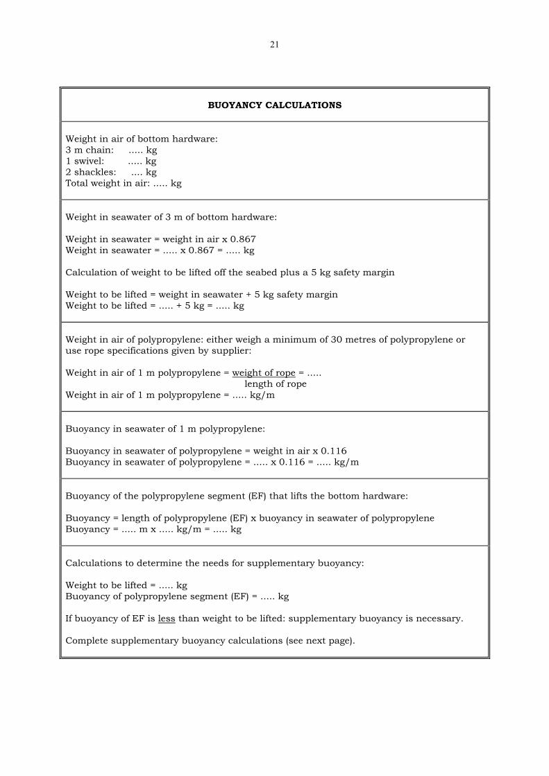
BUOYANCY CALCULATIONS Weight in air of bottom hardware: 3 m chain: ..... kg 1 swivel: ..... kg 2 shackles: .... kg Total weight in air: ..... kg Weight in seawater of 3 m of bottom hardware: Weight in seawater = weight in air x 0.867 Weight in seawater = ..... x 0.867 = ..... kg Calculation of weight to be lifted off the seabed plus a 5 kg safety margin Weight to be lifted = weight in seawater + 5 kg safety margin Weight to be lifted = ..... + 5 kg = ..... kg Weight in air of polypropylene: either weigh a minimum of 30 metres of polypropylene or use rope specifications given by supplier: Weight in air of 1 m polypropylene = weight of rope = ..... length of rope Weight in air of 1 m polypropylene = ..... kg/m Buoyancy in seawater of 1 m polypropylene: Buoyancy in seawater of polypropylene = weight in air x 0.116 Buoyancy in seawater of polypropylene = ..... x 0.116 = ..... kg/m Buoyancy of the polypropylene segment (EF) that lifts the bottom hardware: Buoyancy = length of polypropylene (EF) x buoyancy in seawater of polypropylene Buoyancy = ..... m x ..... kg/m = ..... kg Calculations to determine the needs for supplementary buoyancy: Weight to be lifted = ..... kg Buoyancy of polypropylene segment (EF) = ..... kg If buoyancy of EF is less than weight to be lifted: supplementary buoyancy is necessary. Complete supplementary buoyancy calculations (see next page).

22
SUPPLEMENTARY BUOYANCY CALCULATIONS Calculation supplementary buoyancy: Supplementary buoyancy = weight to be lifted – buoyancy of polypropylene (EF) Supplementary buoyancy = ..... kg – ..... kg = ..... kg (1 litre of buoyancy lifts 1 kg of weight)
Float information: brand, size, type
Buoyancy Rated depth
Number of floats needed to supply supplementary buoyancy: Number floats = Supplementary buoyancy = ..... floats Float buoyancy
CALCULATIONS FOR PLACEMENT OF FLOATS ON
POLYPROPYLENE SEGMENT(EF)
1) Calculation for placement of shallowest float on EF: (shallowest float must be below the bottom of the catenary curve) Distance from the bottom hardware to the shallowest float: Distance = EF – (50% of catenary curve BCDE) – 30 m safety margin Distance = ..... – (0.5 x ..... ) – 30 m = ..... m 2) Calculation for placement of deepest float: Maximum depth for deepest float = ½ x depth rating = 0.5 x ..... = ..... m Placement of deepest float = Site depth – (3 m bottom hardware + maximum depth for deepest float) Placement = .... – (3 m + .....) = ..... m Floats should be placed anywhere on EF between calculation (1) and (2)


![Axiom cordages-limited[1]](https://img.dokumen.tips/doc/110x75/5487cea5b4af9f640d8b54b1/axiom-cordages-limited1.jpg)