Embed Size (px)
Citation preview
Betriebsanleitung • Operating InstructionsP
K 0
15
2 B
E/L
(0
70
3)
UnoLine™
DuoLine™
Rotary Vane Pump
UNO/DUO 2.5, DUO 2.5 C
UNO 5
2
Table of contents
Table of contents
1 Preliminary remarks . . . . . . . . . . . . . . . . . . . . . . . . . . . . . . . . . . . . . . . . 31.1 Validity . . . . . . . . . . . . . . . . . . . . . . . . . . . . . . . . . . . . . . . . . . . . . . . . . . . 31.2 Conventions . . . . . . . . . . . . . . . . . . . . . . . . . . . . . . . . . . . . . . . . . . . . . . . 3
2 Safety . . . . . . . . . . . . . . . . . . . . . . . . . . . . . . . . . . . . . . . . . . . . . . . . . . . 52.1 Safety precautions . . . . . . . . . . . . . . . . . . . . . . . . . . . . . . . . . . . . . . . . . . 52.2 Proper use . . . . . . . . . . . . . . . . . . . . . . . . . . . . . . . . . . . . . . . . . . . . . . . . 52.3 Improper use . . . . . . . . . . . . . . . . . . . . . . . . . . . . . . . . . . . . . . . . . . . . . . 5
3 Transport and storage . . . . . . . . . . . . . . . . . . . . . . . . . . . . . . . . . . . . . . 63.1 Transport . . . . . . . . . . . . . . . . . . . . . . . . . . . . . . . . . . . . . . . . . . . . . . . . . 63.2 Storage . . . . . . . . . . . . . . . . . . . . . . . . . . . . . . . . . . . . . . . . . . . . . . . . . . . 6
4 Product description . . . . . . . . . . . . . . . . . . . . . . . . . . . . . . . . . . . . . . . . 74.1 Product identification . . . . . . . . . . . . . . . . . . . . . . . . . . . . . . . . . . . . . . . . 74.2 Design and function . . . . . . . . . . . . . . . . . . . . . . . . . . . . . . . . . . . . . . . . . 8
5 Installation . . . . . . . . . . . . . . . . . . . . . . . . . . . . . . . . . . . . . . . . . . . . . . . 85.1 Setting up the pump . . . . . . . . . . . . . . . . . . . . . . . . . . . . . . . . . . . . . . . . . 85.2 Filling up the operating fluid . . . . . . . . . . . . . . . . . . . . . . . . . . . . . . . . . . . 95.3 Connecting the vacuum side . . . . . . . . . . . . . . . . . . . . . . . . . . . . . . . . . 105.4 Connecting the exhaust side . . . . . . . . . . . . . . . . . . . . . . . . . . . . . . . . . 115.5 Connecting to the mains power supply . . . . . . . . . . . . . . . . . . . . . . . . . 12
6 Operation . . . . . . . . . . . . . . . . . . . . . . . . . . . . . . . . . . . . . . . . . . . . . . . 146.1 Before switching on the pump . . . . . . . . . . . . . . . . . . . . . . . . . . . . . . . . 146.2 Switching on the pump . . . . . . . . . . . . . . . . . . . . . . . . . . . . . . . . . . . . . . 146.3 Pumping condensable vapours . . . . . . . . . . . . . . . . . . . . . . . . . . . . . . . 146.4 Switching off the pump . . . . . . . . . . . . . . . . . . . . . . . . . . . . . . . . . . . . . . 17
7 Maintenance . . . . . . . . . . . . . . . . . . . . . . . . . . . . . . . . . . . . . . . . . . . . . 187.1 Precautions . . . . . . . . . . . . . . . . . . . . . . . . . . . . . . . . . . . . . . . . . . . . . . 187.2 Changing the operating fluid . . . . . . . . . . . . . . . . . . . . . . . . . . . . . . . . . 18
8 Shutdown . . . . . . . . . . . . . . . . . . . . . . . . . . . . . . . . . . . . . . . . . . . . . . . 208.1 Shutting down for longer periods . . . . . . . . . . . . . . . . . . . . . . . . . . . . . . 208.2 Restarting the pump . . . . . . . . . . . . . . . . . . . . . . . . . . . . . . . . . . . . . . . . 208.3 Disposal . . . . . . . . . . . . . . . . . . . . . . . . . . . . . . . . . . . . . . . . . . . . . . . . . 20
9 Malfunctions . . . . . . . . . . . . . . . . . . . . . . . . . . . . . . . . . . . . . . . . . . . . . 219.1 Troubleshooting . . . . . . . . . . . . . . . . . . . . . . . . . . . . . . . . . . . . . . . . . . . 22
10 Service . . . . . . . . . . . . . . . . . . . . . . . . . . . . . . . . . . . . . . . . . . . . . . . . . 23
11 Spare parts . . . . . . . . . . . . . . . . . . . . . . . . . . . . . . . . . . . . . . . . . . . . . . 2411.1 Spare parts package . . . . . . . . . . . . . . . . . . . . . . . . . . . . . . . . . . . . . . . 24
12 Accessories . . . . . . . . . . . . . . . . . . . . . . . . . . . . . . . . . . . . . . . . . . . . . 27
13 Technical data . . . . . . . . . . . . . . . . . . . . . . . . . . . . . . . . . . . . . . . . . . . 2813.1 Dimensions . . . . . . . . . . . . . . . . . . . . . . . . . . . . . . . . . . . . . . . . . . . . . . 29

Preliminary remarks
1 Preliminary remarks
1.1 ValidityThis operating manual is for customers of Pfeiffer Vacuum. It describes the func-
tioning of the designated product and provides the most important information for
safe use of the unit. The description follows applicable EU guidelines. All informa-
tion provided in this operating manual refer to the current state of the product's de-
velopment. The documentation remains valid as long as the customer does not
make any changes to the product.
Up-to-date operating instructions can also be downloaded from
www.pfeiffer-vacuum.net.
Applicable docu-
ments
*also available via www.pfeiffer-vacuum.net
1.2 Conventions
Safety instructions The safety instructions in Pfeiffer Vacuum operating manuals are the result of risk
evaluations and hazard analyses and are oriented on international certification
standards as specified by UL, CSA, ANSI Z-535, Semi-S1, ISO 3864 and DIN 4844.
In this document, the following hazard levels and information are considered:
UNO/DUO 2.5, UNO 5 Operating instructions
Safety information for vacuum pumps "Safety Guide" PT 0300 BN*
Declaration of Conformity Part of this document
Operating instructions for accessories (order-specifically) see section "accessories"*
DANGER
Immediate danger
Death or very severe injuries occur.
WARNING
Possible danger
Death or injuries may occur.
CAUTION
Possible danger
Medium to slight injuries may occur.
NOTE
Command or note
Command to perform an action or information about properties, the disregarding of which may result in damage to the product.
3
Preliminary remarks
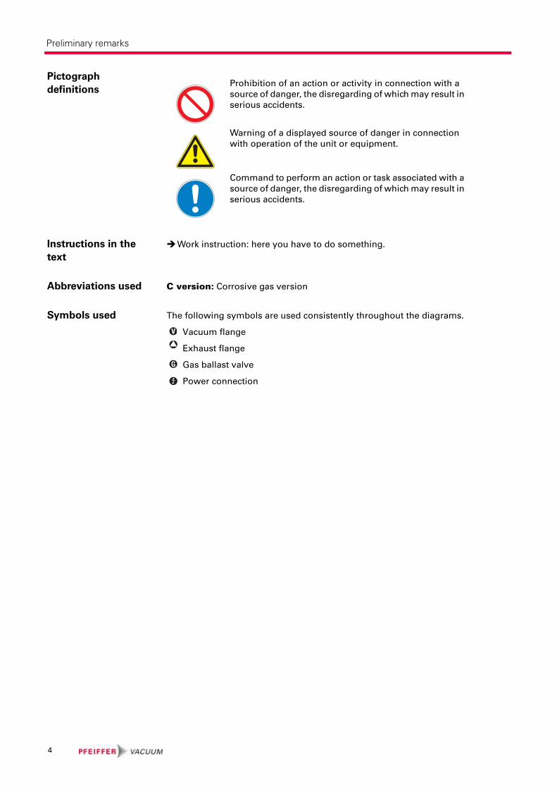
Pictograph
definitions
Instructions in the
text
Work instruction: here you have to do something.
Abbreviations used C version: Corrosive gas version
Symbols used The following symbols are used consistently throughout the diagrams.
Vacuum flange
Exhaust flange
Gas ballast valve
Power connection
Prohibition of an action or activity in connection with a
source of danger, the disregarding of which may result in
serious accidents.
Warning of a displayed source of danger in connection
with operation of the unit or equipment.
Command to perform an action or task associated with a
source of danger, the disregarding of which may result in
serious accidents.
V
G
4
Safety
2 Safety
2.1 Safety precautions
• Do not expose any body parts to the vacuum.
• Observe the safety and accident prevention regulations.
• Check regularly that all safety precautions are being complied with.
• Do not carry out any unauthorised modifications or conversions to the pumps.
• Depending on the operating and ambient conditions, the surface temperature of
the pumps may rise above 70 °C. Use suitable finger guards if necessary.
• When returning the pump to us please note the instructions in the Service sec-
tion.
2.2 Proper use
• The vacuum pump may only be used to generate a vacuum.
• Installation, operating and maintenance regulations must be complied with.
• Using accessories not mentioned in this manual is not permitted without autho-
risation from Pfeiffer Vacuum.
2.3 Improper useImproper use will cause all claims for liability and guarantees to be forfeited. Im-
proper use is deemed to be all use for purposes deviating from those mentioned
above, especially:
• Pumping of corrosive gases (with exception of corrosiv gas versions).
• Pumping of explosive media.
• Operation of the pump in potentially explosive areas.
• Pumping of gases containing impurities such as particles, dusts and condensate;
note the vapour compatibility levels of the pump.
• Pumping of substances that tend to sublime.
• Use of the vacuum pump to generate pressure.
• Pumping of liquids.
• Connection to pumps or units which are not suitable for this purpose according
to their operating instructions.
• Connection to units which have touchable and voltage carrying parts.
NOTE
Duty to inform
Each person involved in the installation, operation or maintenance of the vacuum pump must read and observe the safety-related parts of these operating instructions.
Absolute observe the safety information for vacuum pumps (PT 0300 BN) !The operator is obligated to make operating personnel aware of dangers originating from the vacuum pump, the pumped medium and the entire system.
NOTE
CE conformity
The manufacturer's declaration of conformity becomes invalid if the operator modifies the original product or installs additional components.
Following installation into a plant and before commissioning, the operator must check the entire system for compliance with the valid EU directives and reassess it accordingly.
5
Transport and storage
3 Transport and storage
3.1 Transport
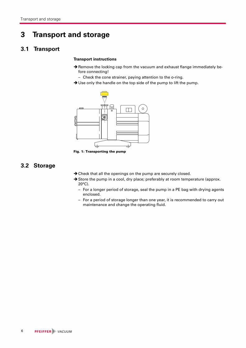
Transport instructions
Remove the locking cap from the vacuum and exhaust flange immediately be-
fore connecting!
– Check the cone strainer, paying attention to the o-ring.
Use only the handle on the top side of the pump to lift the pump.
Fig. 1: Transporting the pump
3.2 Storage
Check that all the openings on the pump are securely closed.
Store the pump in a cool, dry place; preferably at room temperature (approx.
20°C).
– For a longer period of storage, seal the pump in a PE bag with drying agents
enclosed.
– For a period of storage longer than one year, it is recommended to carry out
maintenance and change the operating fluid.
10
6
Product description
4 Product description
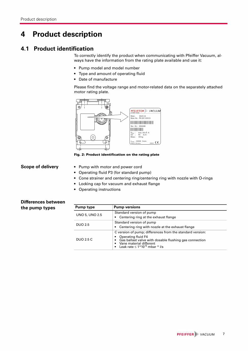
4.1 Product identificationTo correctly identify the product when communicating with Pfeiffer Vacuum, al-
ways have the information from the rating plate available and use it:
• Pump model and model number
• Type and amount of operating fluid
• Date of manufacture
Please find the voltage range and motor-related data on the separately attached
motor rating plate.
Fig. 2: Product identification on the rating plate
Scope of delivery • Pump with motor and power cord
• Operating fluid P3 (for standard pump)
• Cone strainer and centering ring/centering ring with nozzle with O-rings
• Locking cap for vacuum and exhaust flange
• Operating instructions
Differences between
the pump types
D-35641 Asslar
Mod.: DUO 2.5Mod.-Nr.: PK D31 XXX D
Ser.- Nr.: 3454440
S : max. XX m /hOil : P3 X.X l Mass : XX kg
n : XXXX 1/min
(N )23
max.Made in Germany 2005/01
Pump type Pump versions
UNO 5, UNO 2.5Standard version of pump
• Centering ring at the exhaust flange
DUO 2.5Standard version of pump
• Centering ring with nozzle at the exhaust flange
DUO 2.5 C
C version of pump; differences from the standard version:
• Operating fluid F4• Gas ballast valve with dosable flushing gas connection• Vane material different• Leak rate ≤ 1*10-5 mbar * l/s
7
Installation
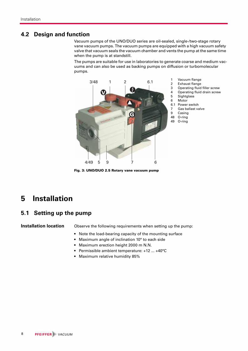
4.2 Design and functionVacuum pumps of the UNO/DUO series are oil-sealed, single-/two-stage rotary
vane vacuum pumps. The vacuum pumps are equipped with a high vacuum safety
valve that vacuum seals the vacuum chamber and vents the pump at the same time
when the pump is at standstill.
The pumps are suitable for use in laboratories to generate coarse and medium vac-
uums and can also be used as backing pumps on diffusion or turbomolecular
pumps.
Fig. 3: UNO/DUO 2.5 Rotary vane vacuum pump
5 Installation
5.1 Setting up the pump
Installation location Observe the following requirements when setting up the pump:
• Note the load-bearing capacity of the mounting surface
• Maximum angle of inclination 10° to each side
• Maximum erection height 2000 m N.N.
• Permissible ambient temperature: +12 ... +40°C
• Maximum relative humidity 85%
1 Vacuum flange
2 Exhaust flange
3 Operating fluid filler screw
4 Operating fluid drain screw
5 Sightglass
6 Motor
6.1 Power switch
7 Gas ballast valve
9 Casing
48 O-ring
49 O-ring
1 2 6.13/48
4/49 5 9 7 6
8
Installation
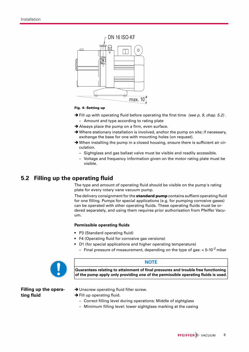
Fig. 4: Setting up
Fill up with operating fluid before operating the first time (see p. 9, chap. 5.2) .
– Amount and type according to rating plate
Always place the pump on a firm, even surface.
Where stationary installation is involved, anchor the pump on site; if necessary,
exchange the base for one with mounting holes (on request).
When installing the pump in a closed housing, ensure there is sufficient air cir-
culation.
– Sightglass and gas ballast valve must be visible and readily accessible.
– Voltage and frequency information given on the motor rating plate must be
visible.
5.2 Filling up the operating fluidThe type and amount of operating fluid should be visible on the pump's rating
plate for every rotary vane vacuum pump.
The delivery consignment for the standard pump contains suffient operating fluid
for one filling. Pumps for special applications (e.g. for pumping corrosive gases)
can be operated with other operating fluids. These operating fluids must be or-
dered separately, and using them requires prior authorisation from Pfeiffer Vacu-
um.
Permissible operating fluids
• P3 (Standard operating fluid)
• F4 (Operating fluid for corrosive gas versions)
• D1 (for special applications and higher operating temperature)
– Final pressure of measurement, depending on the type of gas: < 5·10-2 mbar
Filling up the opera-
ting fluid
Unscrew operating fluid filler screw.
Fill up operating fluid.
– Correct filling level during operations: Middle of sightglass
– Minimum filling level: lower sightglass marking at the casing
max. 10˚
10
DN 16 ISO-KF
NOTE
Guarantees relating to attainment of final pressures and trouble free functioning
of the pump apply only providing one of the permissible operating fluids is used.
9

Installation
Fig. 5: Filling up the operating fluid
Screw in operating fluid filler screw 3.
Check operating fluid level only when the pump is warm and running; close
– vacuum flange and gas ballast valve to do so.
– Check operating fluid daily in non-stop operation, otherwise whenever the
pump is switched on. Refilling is possible when the pump is in final vacuum
operation.
5.3 Connecting the vacuum side
Before attaching the piping at the vacuum flange remove locking cap and insert
protective strainer with the respective O-ring.
The connection between the pump and the recipient should be kept as short as
possible.
– Depending on the pump type, use metallic hoses or PVC hoses with flange
connections.
– Separators, filters etc. may be installed upstream to protect the pump (see ac-
cessories). However, please observe the loss of pumping capacity due to the
conductivity of the accessories.
If a protective strainer is inserted into the intake port, the suction capacity loss is
negligible.
max.
min.
10
53
WARNING
Toxic vapours!
Danger of poisoning when igniting and heating synthetic operating fluids (e.g. F4/F5) above 300°C.
Observe the application instructions of the operating fluid manufacturer.Do not allow operating fluid to make contact with tobacco products; observe safety precautions when handling chemicals.
10
Installation
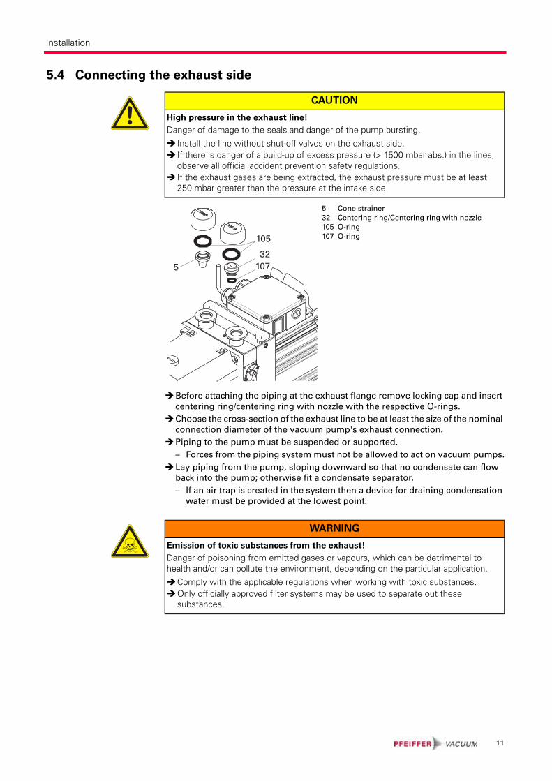
5.4 Connecting the exhaust side
Before attaching the piping at the exhaust flange remove locking cap and insert
centering ring/centering ring with nozzle with the respective O-rings.
Choose the cross-section of the exhaust line to be at least the size of the nominal
connection diameter of the vacuum pump's exhaust connection.
Piping to the pump must be suspended or supported.
– Forces from the piping system must not be allowed to act on vacuum pumps.
Lay piping from the pump, sloping downward so that no condensate can flow
back into the pump; otherwise fit a condensate separator.
– If an air trap is created in the system then a device for draining condensation
water must be provided at the lowest point.
CAUTION
High pressure in the exhaust line!
Danger of damage to the seals and danger of the pump bursting.
Install the line without shut-off valves on the exhaust side.If there is danger of a build-up of excess pressure (> 1500 mbar abs.) in the lines, observe all official accident prevention safety regulations.If the exhaust gases are being extracted, the exhaust pressure must be at least 250 mbar greater than the pressure at the intake side.
5 Cone strainer
32 Centering ring/Centering ring with nozzle
105 O-ring
107 O-ring105
532
107
WARNING
Emission of toxic substances from the exhaust!
Danger of poisoning from emitted gases or vapours, which can be detrimental to health and/or can pollute the environment, depending on the particular application.
Comply with the applicable regulations when working with toxic substances.Only officially approved filter systems may be used to separate out these substances.
11
Installation
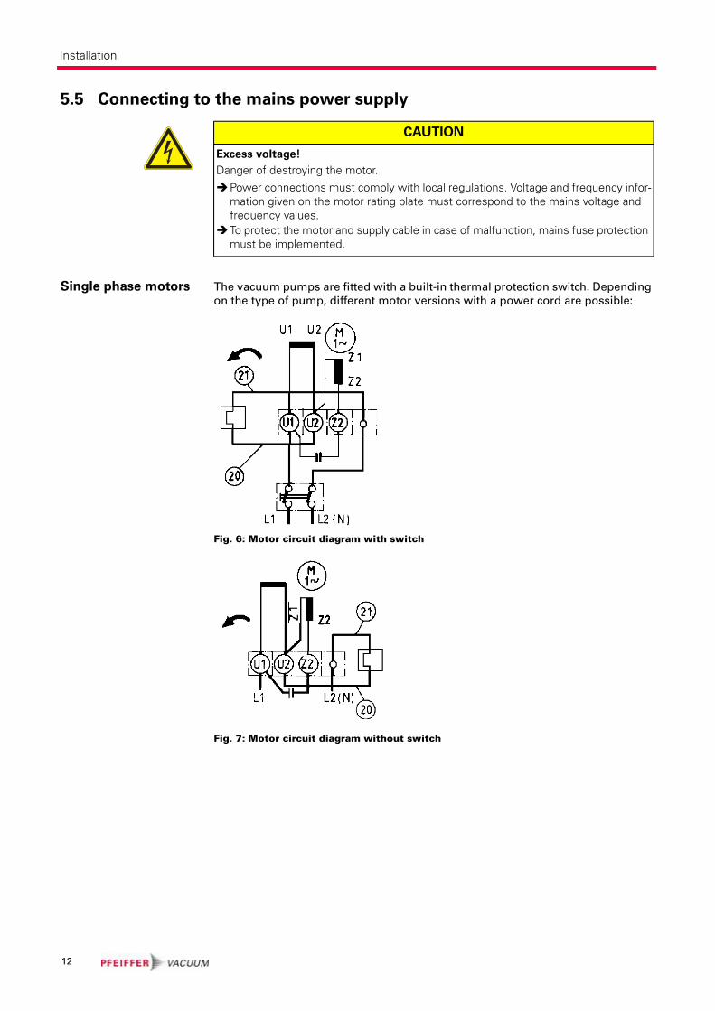
5.5 Connecting to the mains power supply
Single phase motors The vacuum pumps are fitted with a built-in thermal protection switch. Depending
on the type of pump, different motor versions with a power cord are possible:
Fig. 6: Motor circuit diagram with switch
Fig. 7: Motor circuit diagram without switch
CAUTION
Excess voltage!
Danger of destroying the motor.
Power connections must comply with local regulations. Voltage and frequency infor-mation given on the motor rating plate must correspond to the mains voltage and frequency values.To protect the motor and supply cable in case of malfunction, mains fuse protection must be implemented.
12
Installation
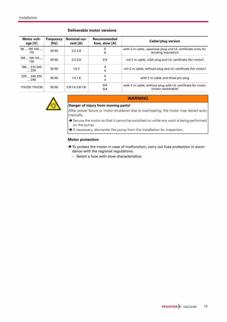
Deliverable motor versions
Motor protection
To protect the motor in case of malfunction, carry out fuse protection in accor-
dance with the regional regulations.
– Select a fuse with slow characteristics.
Motor volt-
age [V]
Frequency
[Hz]
Nominal cur-
rent [A]
Recommended
fuse, slow [A] Cable/plug version
95 ... 105 100 ... 115
50 60 3.2 3.86
6
with 2 m cable, Japanese plug und UL certificate (only for winding insulation)
100 ... 105 110 ... 130
50 60 3.2 3.6 6 6 mit 2 m cable, USA plug and UL certificate (for motor)
190 ... 210 200 ... 220
50 60 1.6 24
4mit 2 m cable, without plug and UL certificate (for motor)
220 ... 240 220 ... 240
50 60 1.4 1.84
4with 2 m cable and three-pin plug
115/230 115/230 50 60 2.8/1.4 3.6/1.8/6/4
6/4
with 2 m cable, without plug with UL certificate for motor (motor switchable)
WARNING
Danger of injury from moving parts!
After power failure or motor shutdown due to overheating, the motor may restart auto-matically.
Secure the motor so that it cannot be switched on while any work is being performed on the pump.If necessary, dismantle the pump from the installation for inspection.
13

Operation
6 Operation
6.1 Before switching on the pump
Check the operating fluid level in the sightglass.
Compare the voltage and frequency information on the rating plate with the
mains voltage and frequency values.
Check that the exhaust connection allows free flow (max. permissible pressure
1.5 bar absolute).
– Activate the shut-off valves in such a way that they open before or at the same
time as the pump is started.
Protect the pump sufficiently from taking in contaminants by means of suitable
precautions (e.g. dust filters); if necessary, check operating fluid regularly or re-
place at shorter intervals.
6.2 Switching on the pumpThe pump can be switched on in any pressure range.
No special precautions are necessary when pumping dry gases. In order to attain
the lowest possible final pressures, the gas ballast valve should be closed.
6.3 Pumping condensable vapoursShould the process gases contain condensable gases present at high percentages,
the rotary vane pump must be operated with a gas ballast (i.e. with an open gas
ballast valve).
Gas ballast valve,
standard version
To avoid condensation in the pump when pumping condensable vapours, air is pe-
riodically fed into the working chamber at the beginning of the compression phase
via the gas ballast valve 7.
The gas ballast valve is closed when turning to the right to position 0 and open
when turning to the left to position 1. Intermediate settings are not possible.
CAUTION
Hot surface!
Danger of burns if hot parts are touched. Depending on the operating and ambient conditions, the surface temperature of the pump may rise above 70 °C.
In this case, use suitable finger guards.
CAUTION
Bad final vacuum and damage to the pump!
Danger of condensation and corrosion due to exceeding the water vapour compatibi-lity (see Technical data) during operation without a gas ballast or in case of insufficient supply of flushing gas.
Only pump vapours when the pump is warm and the gas ballast valve is open.When the process has been completed, allow the pump to continue running for about 30 minutes with the vacuum flange closed and the gas ballast open for ope-rating fluid regeneration purposes.
14
Operation
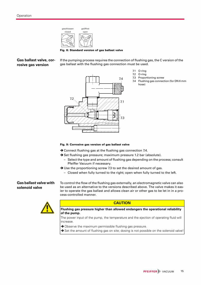
Fig. 8: Standard version of gas ballast valve
Gas ballast valve, cor-
rosive gas version
If the pumping process requires the connection of flushing gas, the C version of the
gas ballast with the flushing gas connection must be used.
Fig. 9: Corrosive gas version of gas ballast valve
Connect flushing gas at the flushing gas connection 7.4.
Set flushing gas pressure; maximum pressure 1.2 bar (absolute).
– Select the type and amount of flushing gas depending on the process; consult
Pfeiffer Vacuum if necessary.
Use the proportioning screw 7.3 to set the desired amount of gas.
– Closed when fully turned to the right; open when fully turned to the left.
Gas ballast valve with
solenoid valve
To control the flow of the flushing gas externally, an electromagnetic valve can also
be used as an alternative to the versions described above. The valve makes it eas-
ier to operate the gas ballast and allows clean air or other gas to be let in in a pro-
cess-controlled manner.
11 1
00 0
1 0
geschlossen
closed
geöffnet
open
7.1 O-ring
7.2 O-ring
7.3 Proportioning screw
7.4 Flushing gas connection (for DN 6 mm
hose)
7.1
7.3
7.4
7.2
CAUTION
Flushing gas pressure higher than allowed endangers the operational reliability
of the pump.
The power input of the pump, the temperature and the ejection of operating fluid will increase.
Observe the maximum permissible flushing gas pressure.Set the amount of flushing gas on site; dosing is not possible on the solenoid valve!
15
Operation
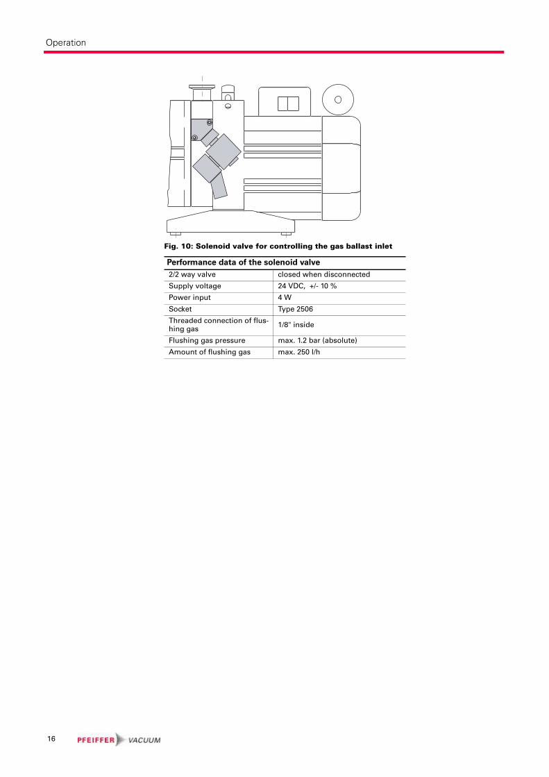
Fig. 10: Solenoid valve for controlling the gas ballast inlet
Performance data of the solenoid valve
2/2 way valve closed when disconnected
Supply voltage 24 VDC, +/- 10 %
Power input 4 W
Socket Type 2506
Threaded connection of flus-hing gas
1/8" inside
Flushing gas pressure max. 1.2 bar (absolute)
Amount of flushing gas max. 250 l/h
16
Operation
6.4 Switching off the pumpThe pump can be switched off in any pressure range.
Rotary vane pumps have an integrated safety valve on the intake side. If the differ-
ential pressure between the exhaust side and the intake side is ≥ 250 mbar, then
the valve closes automatically and vents the pump when the pump is switched off.
Switch the pump off at the mains switch or disconnect from the mains in a secu-
re manner.
Venting the vacuum
chamber
Maintaining the va-
cuum in the chamber
CAUTION
Danger of backflow of operating fluid into the intake line!
Contamination of the connected vacuum system!
Vent the vacuum chamber within 30 s, regardless of the chamber size.For a longer venting process, use an additional shut-off valve and shut off the intake line after switching off the pump.
CAUTION
Danger of backflow of operating fluid into the intake line!
Contamination of the connected vacuum system!
Because the safety valve of the pump is not suitable for longer-term sealing, install an additional shut-off valve in the intake line.Shut off the intake line immediately after switching off the pump.
17
Maintenance
7 Maintenance
7.1 Precautions
Allow the pump to cool to a safe temperature.
Only dismantle the pump as far as necessary in order to repair defects.
Dispose of used operating fluid in compliance with local regulations.
When using synthetic operating fluids or working with toxic substances or sub-
stances contaminated with corrosive gases, the relevant instructions governing
their use must be observed.
Use only alcohol or similar agents for cleaning pump parts.
7.2 Changing the operating fluidThe changing interval for the operating fluid depends on the pump applications.
Change the operating fluid at least once every year.
The level of deterioration of operating fluid P3 can be read off the colour scale in
accordance with DIN 51578; request the supplementary sheet PK 0219 BN or
download it from the Internet.
Fill the specimen in a test tube or some similar vessel and test by holding against
the light.
Where discolouration is dark yellow to red brown (equivalent to 4 ... 5 on the sca-
le) change operating fluid.
Switch off pump.
Unscrew operating fluid drain screw 4 and drain operating fluid.
WARNING
Danger of injury from moving parts!
After power failure or motor shutdown due to overheating, the motor may restart auto-matically.
Secure the motor so that it cannot be switched on while any work is being performed on the pump.If necessary, dismantle the pump from the installation for inspection.
WARNING
Pump parts may be contaminated from pumped media!
Danger of poisoning due to contact with harmful substances.
Decontaminate the pump before carrying out any maintenance work.In the event of contamination, take suitable safety precautions to prevent your health from being harmed by any dangerous substances.
NOTE
Depending on the applications, Pfeiffer Vacuum recommends determining the
exact service life of the operating fluid during the first year of operation.
The replacement interval may vary from the guide value specified by Pfeiffer Vacuum depending on the thermal and chemical loads, and the accumulation of suspended par-ticles and condensation in the operating fluid.
18
Maintenance
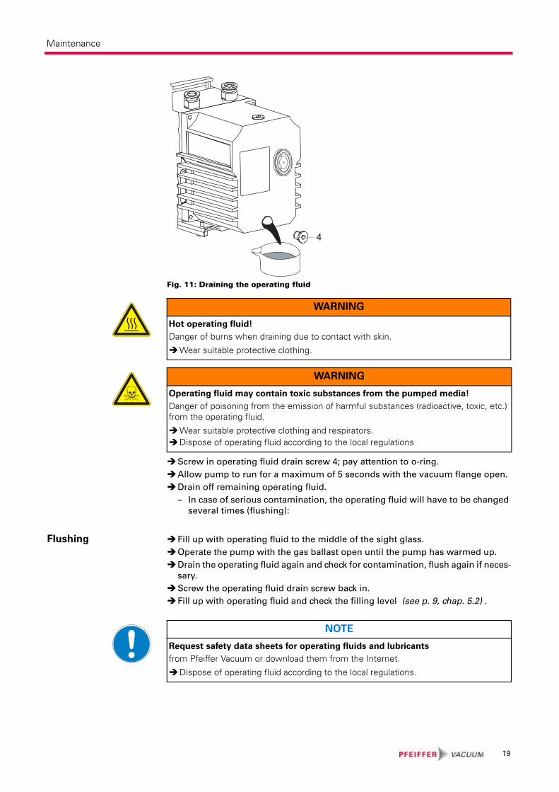
Fig. 11: Draining the operating fluid
Screw in operating fluid drain screw 4; pay attention to o-ring.
Allow pump to run for a maximum of 5 seconds with the vacuum flange open.
Drain off remaining operating fluid.
– In case of serious contamination, the operating fluid will have to be changed
several times (flushing):
Flushing Fill up with operating fluid to the middle of the sight glass.
Operate the pump with the gas ballast open until the pump has warmed up.
Drain the operating fluid again and check for contamination, flush again if neces-
sary.
Screw the operating fluid drain screw back in.
Fill up with operating fluid and check the filling level (see p. 9, chap. 5.2) .
4
WARNING
Hot operating fluid!
Danger of burns when draining due to contact with skin.
Wear suitable protective clothing.
WARNING
Operating fluid may contain toxic substances from the pumped media!
Danger of poisoning from the emission of harmful substances (radioactive, toxic, etc.) from the operating fluid.
Wear suitable protective clothing and respirators.Dispose of operating fluid according to the local regulations
NOTE
Request safety data sheets for operating fluids and lubricants
from Pfeiffer Vacuum or download them from the Internet.
Dispose of operating fluid according to the local regulations.
19
Shutdown
8 Shutdown
8.1 Shutting down for longer periodsBefore shutting down the pump, observe the following procedure and adequately
protect the pump system against corrosion:
Switch off pump.
Change operating fluid (see p. 18, chap. 7.2) .
Start the pump and allow the pump to warm up.
Fill up the pump with new operating fluid to the top edge of the sightglass.
Close vacuum flange and exhaust flange with locking caps.
8.2 Restarting the pumpVisually inspect the inner of the pump before taking it into operation. If there is ev-
idence of rust on the parts of the pump which form the housing then do not take it
into operation and contact Pfeiffer Vacuum Service.
Depending on how long the pump is taken out of operation, it may be necessary to
replace the radial shaft sealing rings. With reference to DIN 7716 and the manufac-
turer's specifications we recommend replacing the installed elastomer parts after
2 years.
If drying pearls were inserted then they should be removed now. Improper hand-
ling can cause failure of the pump.
8.3 DisposalProducts or parts thereof (mechanical and electrical components, operating fluids,
etc.) may cause environmental burden.
Safely dispose of the materials according to the locally applicable regulations.
CAUTION
Emission of operating fluid!
Danger of the operating fluid being emitted at the exhaust flange if overfilled.
Drain the operating fluid to the normal level before restarting the pump.
20

Malfunctions
9 MalfunctionsPlease note the following instructions should the pump malfunction:
CAUTION
Hot surface!
Danger of burns if hot parts are touched. The surface temperature of the pump may rise above 105 °C in case of malfunction.
Carry out work on the pump only after it has cooled to a safe temperature.
NOTE
Motor overload!
Depending on the malfunction (e.g. blocking during cold start), the motor may not be sufficiently protected by the built-in thermal protection switch from damage through overheating.
Implement an additional network safety device.
21

Malfunctions
9.1 Troubleshooting
Problem Possible causes Remedy
Pump will not start up
No mains voltage or voltage does not correspond to the motor data
Check mains voltage and mains fuse protection; check motor switch
Pump temperature too low Warm up pump to > 12°C
Thermal protection switch has responded
Detect and fix cause of overheating; allow pump to cool off if necessary.
Pump system dirtyClean pump; contact Pfeiffer Vacuum Service if necessary.
Pump system damagedClean and overhaul pump; contact Pfeiffer Vacuum Service if necessary.
Motor defective Replace motor
Pump switches off after a while after being started
Thermal protection switch of the motor has responded
Detect and fix cause of overheating; allow motor to cool off if necessary.
Mains fuse protection trigge-red due to overload (e.g. cold start)
Warm up pump
Exhaust pressure too highCheck opening of exhaust line and exhaust accessories
Pump does not attain final pres-sure
Measurement reading is falseCheck gauge, check final pressure wit-hout installation connected.
Pump or connected accesso-ries are dirty
Clean pump and check components for contamination.
Operating fluid dirtyOperate pump for a longer period with gas ballast valve open or change ope-rating fluid
Leak in system Repair leak
Operating fluid filling level too low
Top off operating fluid
Pump damaged Contact Pfeiffer Vacuum Service.
Pumping speed of pump too low
Intake line not well-dimensio-ned
Keep connections as short as possible and see that cross-sections are suffi-ciently dimensioned
Exhaust pressure too highCheck opening of exhaust line and exhaust accessories
Loss of operating fluid
Swivel gasket leakyCheck tightness; replace gasket if necessary
Radial shaft seal ring leaky Replace seal ring and check bushing
Operational loss of operating fluid
If necessary, install oil mist filter and oil return unit
Unusual operating noises
Silencer dirty Clean or replace the silencer.
Damage to the pump systemClean and overhaul pump; contact Pfeiffer Vacuum Service if necessary.
Motor bearing defectiveReplace motor; contact Pfeiffer Vacuum Service if necessary
NOTE
Service work should only be carried out by qualified personal!
Pfeiffer Vacuum is not liable for any damage to the pump resulting from work carried out improperly.
Take advantage of our service training programs from technical training; additional information at www.pfeiffer-vacuum.net.Please state all the information on the pump rating plate when ordering spare parts.
22
Service
10 ServicePfeiffer Vacuum offers first-class service!
• Maintenance/repairs on the spot by Pfeiffer Vacuum field service
• Maintenance/repairs in the nearby service center or service point
• Fast replacement with exchange products in mint condition
• Advice on the most cost-efficient and quickest solution
Detailed information and addresses at: www.pfeiffer-vacuum.net (Service).
Maintenance and repairs in the Pfeiffer Vacuum ServiceCenter
The following steps are necessary to ensure a fast, smooth servicing process:
Download the RMA1) form and contamination declaration.
Fill in the RMA form and send it by fax or e-mail to your service address.
Enclose the RMA confirmation of receipt from Pfeiffer Vacuum in the shipment.
Fill in the contamination declaration and enclose it in the shipment (required!).
Dismantle all accessories.
Drain operating fluid/lubricant.
Drain cooling medium, if used.
Send the pump in its original packaging if at all possible.
Returning contaminated vacuum pumps
Units which are microbiologically, explosively or radioactively contaminated will
not be accepted by Pfeiffer Vacuum as a matter of principle. Hazardous substances
are substances and compounds in accordance with the hazardous goods directive
(current version). Should pumps be contaminated or the contamination declara-
tion be missing, Pfeiffer Vacuum will decontaminate the pumps at your cost.
Returning contaminated pumps or units
Neutralise the pump by flushing it with nitrogen or dry air.
Close off all openings so that they are air-tight.
Seal the pump or unit in suitable protective film.
Only return the pump/unit in a suitable and sturdy transport container.
All service orders are carried out exclusively according to our repair conditions for
vacuum units and components.
1) RMA: Return Material Authorization
23
Spare parts
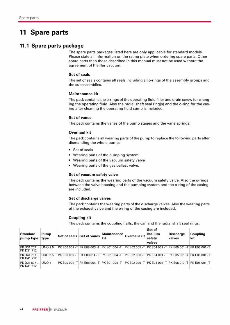
11 Spare parts
11.1 Spare parts packageThe spare parts packages listed here are only applicable for standard models.
Please state all information on the rating plate when ordering spare parts. Other
spare parts than those described in this manual must not be used without the
agreement of Pfeiffer vacuum.
Set of seals
The set of seals contains all seals including all o-rings of the assembly groups and
the subassemblies.
Maintenance kit
The pack contains the o-rings of the operating fluid filler and drain screw for chang-
ing the operating fluid. Also the radial shaft seal ring(s) and the o-ring for the cas-
ing after cleaning the operating fluid sump is included.
Set of vanes
The pack contains the vanes of the pump stages and the vane springs.
Overhaul kit
The pack contains all wearing parts of the pump to replace the following parts after
dismantling the whole pump:
• Set of seals
• Wearing parts of the pumping system
• Wearing parts of the vacuum safety valve
• Wearing parts of the gas ballast valve.
Set of vacuum safety valve
The pack contains the wearing parts of the vacuum safety valve. Also the o-rings
between the valve housing and the pumping system and the o-ring of the casing
are included.
Set of discharge valves
The pack contains the wearing parts of the discharge valves. Also the wearing parts
of the exhaust valve and the o-ring of the casing are included.
Coupling kit
The pack contains the coupling halfs, the can and the radial shaft seal rings.
Standard
pump type
Pump
typeSet of seals Set of vanes
Maintenance
kitOverhaul kit
Set of
vacuum
safety
valves
Discharge
valves
Coupling
kit
PK D31 707 ... PK D31 712
UNO 2.5 PK E00 002 -T PK E08 003 -T PK E01 004 -T PK E02 005 -T PK E04 001 -T PK E05 001 -T PK E06 001 -T
PK D41 707 ... PK D41 712
DUO 2.5 PK E00 002 -T PK E08 014 -T PK E01 004 -T PK E02 008 -T PK E04 001 -T PK E05 001 -T PK E06 001 -T
PK D31 807 ... PK D31 812
UNO 5 PK E00 002 -T PK E08 004 -T PK E01 004 -T PK E02 026 -T PK E04 007 -T PK E05 010 -T PK E06 001 -T
24
Spare parts
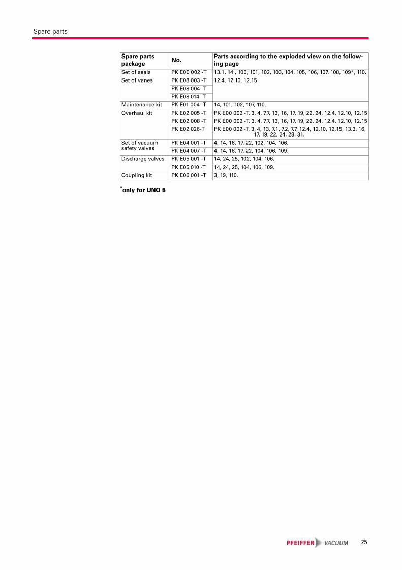
*only for UNO 5
Spare parts
packageNo.
Parts according to the exploded view on the follow-
ing page
Set of seals PK E00 002 -T 13.1, 14 , 100, 101, 102, 103, 104, 105, 106, 107, 108, 109*, 110.
Set of vanes PK E08 003 -T 12.4, 12.10, 12.15
PK E08 004 -T
PK E08 014 -T
Maintenance kit PK E01 004 -T 14, 101, 102, 107, 110.
Overhaul kit PK E02 005 -T PK E00 002 -T, 3, 4, 7.7, 13, 16, 17, 19, 22, 24, 12.4, 12.10, 12.15
PK E02 008 -T PK E00 002 -T, 3, 4, 7.7, 13, 16, 17, 19, 22, 24, 12.4, 12.10, 12.15
PK E02 026-T PK E00 002 -T, 3, 4, 13, 7.1, 7.2, 7.7, 12.4, 12.10, 12.15, 13.3, 16, 17, 19, 22, 24, 28, 31.
Set of vacuumsafety valves
PK E04 001 -T 4, 14, 16, 17, 22, 102, 104, 106.
PK E04 007 -T 4, 14, 16, 17, 22, 104, 106, 109.
Discharge valves PK E05 001 -T 14, 24, 25, 102, 104, 106.
PK E05 010 -T 14, 24, 25, 104, 106, 109.
Coupling kit PK E06 001 -T 3, 19, 110.
25
Spare parts
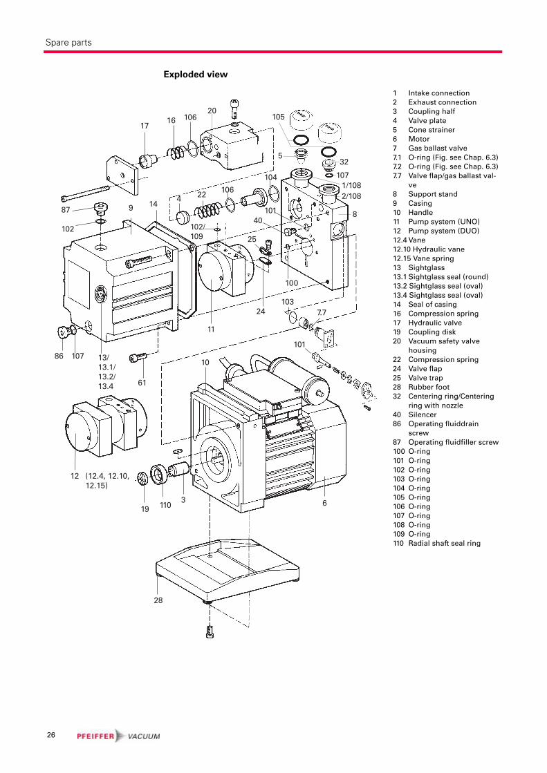
Exploded view
1 Intake connection
2 Exhaust connection
3 Coupling half
4 Valve plate
5 Cone strainer
6 Motor
7 Gas ballast valve
7.1 O-ring (Fig. see Chap. 6.3)
7.2 O-ring (Fig. see Chap. 6.3)
7.7 Valve flap/gas ballast val-
ve
8 Support stand
9 Casing
10 Handle
11 Pump system (UNO)
12 Pump system (DUO)
12.4 Vane
12.10 Hydraulic vane
12.15 Vane spring
13 Sightglass
13.1 Sightglass seal (round)
13.2 Sightglass seal (oval)
13.4 Sightglass seal (oval)
14 Seal of casing
16 Compression spring
17 Hydraulic valve
19 Coupling disk
20 Vacuum safety valve
housing
22 Compression spring
24 Valve flap
25 Valve trap
28 Rubber foot
32 Centering ring/Centering
ring with nozzle
40 Silencer
86 Operating fluiddrain
screw
87 Operating fluidfiller screw
100 O-ring
101 O-ring
102 O-ring
103 O-ring
104 O-ring
105 O-ring
106 O-ring
107 O-ring
108 O-ring
109 O-ring
110 Radial shaft seal ring
1/1082/108
8
7.7
101
61
32
105
5
1061617
10140
104
4 22106
20
12 (12.4, 12.10, 12.15)
107
102/ 109
87
102
9 14
25
100
10324
11
1086 107 13/
13.1/13.2/13.4
28
1103 6
19
26
Accessories
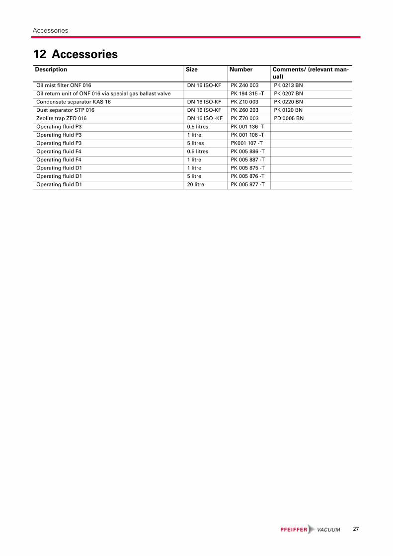
12 AccessoriesDescription Size Number Comments/ (relevant man-
ual)
Oil mist filter ONF 016 DN 16 ISO-KF PK Z40 003 PK 0213 BN
Oil return unit of ONF 016 via special gas ballast valve PK 194 315 -T PK 0207 BN
Condensate separator KAS 16 DN 16 ISO-KF PK Z10 003 PK 0220 BN
Dust separator STP 016 DN 16 ISO-KF PK Z60 203 PK 0120 BN
Zeolite trap ZFO 016 DN 16 ISO -KF PK Z70 003 PD 0005 BN
Operating fluid P3 0.5 litres PK 001 136 -T
Operating fluid P3 1 litre PK 001 106 -T
Operating fluid P3 5 litres PK001 107 -T
Operating fluid F4 0.5 litres PK 005 886 -T
Operating fluid F4 1 litre PK 005 887 -T
Operating fluid D1 1 litre PK 005 875 -T
Operating fluid D1 5 litre PK 005 876 -T
Operating fluid D1 20 litre PK 005 877 -T
27

Technical data
13 Technical dataSize Unit UNO 5 UNO 2.5 DUO 2.5
DUO 2.5 C
Connection nominal diamter
Input
Output
DN 16 ISO-KF
DN 16 ISO-KF
DN 16 ISO-KF
DN 16 ISO-KF
DN 16 ISO-KF
DN 16 ISO-KF
Volume flow rate at
50 Hz
60 Hz
m3/h4.6
5.1
2.5
3.9
2.5
3.9
Final pressure:Total with gas ballast
Final pressure:Total without gas ballastmbar
< 1
< 5 ⋅ 10-2< 1
< 5 ⋅ 10-2< 6 ⋅ 10-3
< 6 ⋅ 10-3
Exhaust pressure, min.
Exhaust pressure, max.mbar
> 250
< 1500
> 250
< 1500
> 250
< 1500
Water vapour compatibility
50 Hz
60 Hz
mbar20
20
15
15
15
15
Water vapour capacity
50 Hz
60 Hz
g/h65
75
26
30
30
34
Noise level without gas ballast dB(A) 55 53 53
Amount of operating fluid l 0.40 0.45 0.4
Min. run-up temperature acc. to
DIN 28 426°C + 12 + 12 + 12
Max. permissible operating temperature
(at 25°C ambient temperature
and operating fluid P3, with gas ballast
°C 80 80 80
Rotation speed at
50 Hz
60 Hz
1/min2880
3420
2880
3420
2880
3420
Rated power, motor
50 Hz
60 Hz
kW 0.15
0.18
0.15
0.18
0.15
0.18
Weight kg 10.5 10.2 10.5
28
Technical data
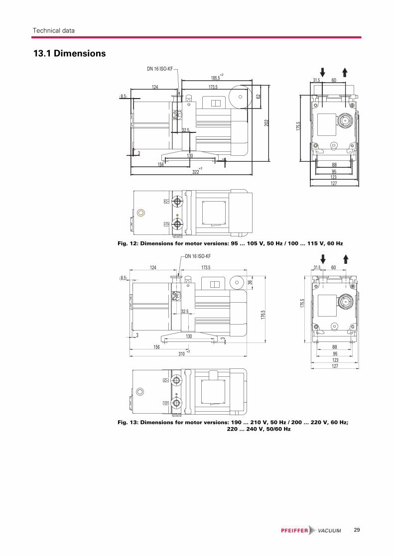
13.1 Dimensions
Fig. 12: Dimensions for motor versions: 95 ... 105 V, 50 Hz / 100 ... 115 V, 60 Hz
Fig. 13: Dimensions for motor versions: 190 ... 210 V, 50 Hz / 200 ... 220 V, 60 Hz; 220 ... 240 V, 50/60 Hz
202
185.5
173.5124
32.5
130
156322
8895
123127
175.5
31.5 60
3
( )8.5
3
62
+2
+2
DN 16 ISO-KF
10
310
124
(( ))8.5
173.517
6.5
130
156
60
8895123
175.5
31.5
127
32.5
33
36
+2
DN 16 ISO-KF
10
29

Technical data
Fig. 14: Dimensions for motor versions: 115/230, 50/60 Hz
Fig. 15: Dimensions for motor versions: 100 ... 105 V, 50 Hz / 110 ... 130 V, 60 Hz
3130
13090
156
336
177
124
200
3
31.5 60
88
95123127
175.5
32.5
310
DN 16 ISO-KF
01
(8.5)
8895
123127
175.5
31.5 60
318
130
156
32.5
124 181.519
4.5
(( ))8.5
33
52DN 16 ISO-KF
10
+2
+2
30
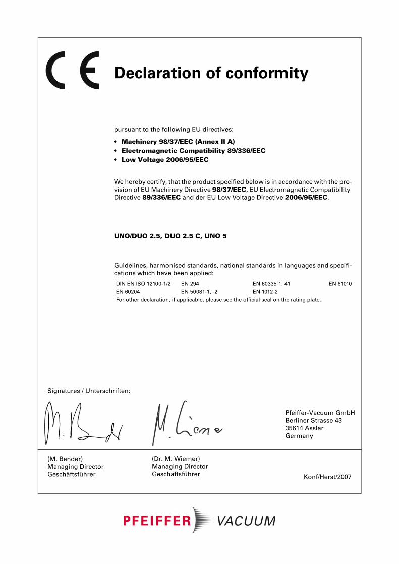
Konf/Herst/2007
Signatures / Unterschriften:
(M. Bender)
Managing Director
Geschäftsführer
(Dr. M. Wiemer)
Managing Director
Geschäftsführer
Pfeiffer-Vacuum GmbH
Berliner Strasse 43
35614 Asslar
Germany
Declaration of conformity
pursuant to the following EU directives:
• Machinery 98/37/EEC (Annex II A)• Electromagnetic Compatibility 89/336/EEC• Low Voltage 2006/95/EEC
We hereby certify, that the product specified below is in accordance with the pro-
vision of EU Machinery Directive 98/37/EEC, EU Electromagnetic Compatibility
Directive 89/336/EEC and der EU Low Voltage Directive 2006/95/EEC.
UNO/DUO 2.5, DUO 2.5 C, UNO 5
Guidelines, harmonised standards, national standards in languages and specifi-
cations which have been applied:
DIN EN ISO 12100-1/2 EN 294 EN 60335-1, 41 EN 61010
EN 60204 EN 50081-1, -2 EN 1012-2
For other declaration, if applicable, please see the official seal on the rating plate.
Pfeiffer Vacuum Technology AG · Headquarters/Germany
Tel. +49-(0) 64 41-8 02-0 · Fax +49-(0) 64 41-8 02-2 02 · [email protected] · www.pfeiffer-vacuum.net
Vacuum is nothing, but everything to us!
Turbopumps
Rotary vane pumps
Roots pumps
Dry compressing pumps
Leak detectors
Valves
Components and feedthroughs
Vacuum measurement
Gas analysis
System engineering
Service


![ZZ - fiqhulhadith.com ki kunjyan.pdf69 ----- *****™™*™™ÒÃÃÃÅÅÅÃÅääää™™™™]]]!!!!***hZZZå 71 -----*****™™™*™ÀÀÀÀÂÂÂÂ6666,,,vvvvZZZ{{{Z{ŠŠŠŠcc**c](https://img.dokumen.tips/doc/110x75/5e5e26f29bdb1829b545ee7d/zz-ki-kunjyanpdf-69-aaaaffffaaaahzzz.jpg)


![Rainbow Heart - artecy.com · 7777777 777777777 7777777777777 ooooooo 77777 7777777 7777777777777 oooooo]]]]] ddd ddd ddd ddd ddd ™™™™™™™™™™™ ™™™™™™™™™™™™™™™™™](https://img.dokumen.tips/doc/110x75/5f4a4ec8ec2fea16bc048a6a/rainbow-heart-7777777-777777777-7777777777777-ooooooo-77777-7777777-7777777777777.jpg)