Embed Size (px)
Citation preview
WEAR E L S E V I E R Wear 209 (1997) 171-178
Unlubricated sliding wear of steels: towards an alternative wear equation
D . W . B o r l a n d , S. B i a n Department of Materials Engineering, Monash Universio', Clayton. Vic. 3168, Australia
Received I 1 September 1996; accepted 15 November 1996
Abstract
Results obtained in pin-on-ring tests of hardened-and-tempered steel are analysed. It is shown that the rate of wear can be related m an 'index of wear intensity'. This index is derived from the external variables of load, sliding speed and the hardness of the two components of the sliding pair. It may be regarded as a measure of the conditions that prevail in the contact zone. © 1997 Elsevier Science S.A.
Keywords: Sliding wear; Wear equation
1. In t roduct ion
There are many factors that influence the rate and mecha- nisms of wear when two materials rub against one another. Even i f we confine our attention to a single class of material, i.e. steel in this case, the list of variables to be considered is formidably long. While almost all the variables involved in wear systems have been studied as factors that can affect wear, most investigations have concentrated on one or a few of them. This is the underlying reason why so little progress has been made towards models of wearing processes that can be used predictively.
Engineering models for wear have been reviewed recently by Bayer [ I ], who emphasizes that, while universal models are not to be expected, there are often ranges of load or speed over which the wearing behaviour is stable and empirical models may be developed. Theoretical models have also been developed to provide a firmer foundation for empirical equa- tions. These are usually based on a particular mechanism of wear; while some of them are very simple, others are com- plex, even allowing for the simultaneous operation of more than one mechanism of wear. The goal of these developments must be to achieve predictive capability, not only of the rate of wear in a particular range of load and speed but also of the limits of the range over which the model is expected to apply. Despite a great deal of investigation there has been little success in attaining this goal; reasons for this failure have been discussed recently by Meng and Ludema [2].
There have been many attempts to develop a taxonomy of wear that would encourage more productive thinking, but we do not need a complex classification for the present discus- sion. Here it is sufficient to distinguish two levels of variables
0043-1648/97/$17.00 © 1997 Elsevier Science S.A. All tights reserved PLIS0043-1648(96 )07478-9
in a wear system: the original macroscopic parameters and ti~e microscopic processes in the contact zone during wear. While we focus our attention on the microscopic processes we must keep in mind that our goal is to link the macroscopic parameters with the final r e s u l t ~ h e rate of wear, which we identify here as the rate of loss of material from the wearing system.
At the microscopic level we may recognize two distinct aspects of the processes that lead to wear. During the relative movement of two surfaces in contact there is transfer between the surfaces as well as removal of material from one or the other surface and ejection from the contact zone in the form of wear debris. At this level the important variables are the properties of the materials and the environment in the contact zone; these must determine the wearing mechanisms. How- ever, the geometry of the surfaces and the mechanics of slid- ing may also affect the rate of ejection, and this in turn may affect the sequence of events that precedes the formation of a debris particle.
At the macroscopic level wear is simply the displacement or removal of material from a surface and is measured by the amount of material loss. At this level we seek to connect the loss of material directly to the external macroscopic variables such as the load and sliding speed. It is at this level that we have had a wear equation for many years, since the work of Arehard [3]. The equation may be stated in different ways; we use the form
V / L = k ( W / H )
where V is the volume of wear, W is the normal load, L is the sliding distance and H is the hardness of one of the sliding materials ( usually the softer). The equation contains a single

172 D.W. Borland, $. Bianl Wear 209(1997) 171-178
parameter pertaining to the wearing material~ its indentation hardness, but it has been widely recognized that such a restric- tion is too simple [4]. Other properties of materials in the wearing system are buried in the value of k, the wear coeffi- cient, which is usually assumed to be constant. It is immedi- ately evident that such an equation can only hold if the properties of the materials participating in the wearing proc- ess are not affected by variations in load or sliding distance. This is a point that is often unrecognized, though Arehard specifically restricted his equation to situations where there was no appreciable temperature rise during sliding.
An equation that takes into account the effect of the wear- ing process on the conditions in the contact zone, and hence the properties of materials in that zone, might be expected to apply over a wider range of conditions. The purpose of this paper is to develop this idea in the context of results that have been obtained during our recent studies of the dry sliding wear of quenched-and-tempered medium-carben steel [ 5,6].
In these experiments we have sought to avoid complica- tions arising from differences between the wearing material and the material of the counterface by using materials for the two surfaces that differ only in their hardness.
2. Experimental details
The results m be discussed here have been published pre- viously [5,6]. They were all obtained in experiments using the pin-on-ring configuration, in which the ends of 7.75 mm diameter pins were pressed against the circumference of 75 mm diameter rings under a dead load. Pins were machined from AISI 1040 steel, oil quenched and tempered to four hardness levels. An alloy steel of the same carbon content (AISI 4140) was used to produce quenched-and-tempered rings of approximately the same four hardness levels, the alloying element content being required to ensure satisfactory quenching. The rate of wear was monitored continuously by measuring the displacement of the pin with respect to the frame of the apparatus; the rates of wear that are reported are those attained in the steady state, which becomes established after a running-in period [6]. In this steady state the two rubbing surfaces are in full conformity, so the area of the contact surface does not vary during the test and the contact conditions are sensibly constant.
The roughness R, of some of the wear tracks on the rings was measured using a stylus instrument. The 'friction tem- perature' Tr was measured by a thermocouple inserted trans- versely in the pin at a point 1.2 mm behind the rubbing surface.
Results of all the tests a~ pre.sented in Table I. It will be seen that most tests were run at constant load and speed, varying the hardness of pin and ring. A smaller number of tests was run with constant hardness of pin and ring, varying the load or the rubbing speed.
3. I)iscussion
3.1. The influence o f hardness on wear
Many investigations have been carried out with the aim of correlating wearing behaviour with the mechanical properties of the participating materials. Most of them have used hard- ness as a measure of mechanical properties, for readily under- standable reasons: it is easy to measure on the specimens to be used and is related, however indirectly, to the yield and tensile strengths, which are perceived as important determin- ing properties for wear resistance. Ductility and other para- meters relating to resistance to fracture, such as fracture toughness, have often been mentioned as being important in wearing mechanisms, but there have been few attempts to establish direct correlations between such properties and rates of wear. Hardness, therefore, is the mechanical property that deserves closer examination.
The role ofharduess has been reviewed recently by Riguey [4]. The original hardness of the softer of two materials sliding against one another is not necessarily the most appro- priate value for use in awearequation. Forexample, Kalousek et al. [7] have found high hardness values near the worn surface of peaditic steel and this higher hardness could be correlated with the wear resistance. Hardness after wear may thus be more relevant in certain cases, but if any measure of hardness is to be used it should ideally be the hardness during wear, although that may be difficult to measure. As Riguey has emphasized, it must also be recognized that in many wearing processes there is formed on one or both surfaces a transfer layer, or tribo-layer, consisting of a mechanical mix- ture of extremely fine particles. Godet [8] has drawn atten- tion to this layer, considered as a 'third body' whose properties may determine the rate of wear. Godet is concerned with the plastic properties of the third body, looking towards mechanisms of debris generation that depend on plastic flow, but in the present context we merely note that the hardness of this layer should not be ignored.
Most published literature shows wear test results for con- stant hardness of one part (usually the moving part), chang- ing the hardness of the other part to obtain a relationship between its hardness and its rate of wear. The fact that wear is a result of the behaviour of a system means that when materials of differing properties are robbing together the wearing behaviour depends on the geometry and the kine- matics of each component. Specifically, in pin-on-ring wear tests it matters which component is used as the pin and which component as the ring; different results are obtained when the pin and the ring material are interchanged. This obser- vation has been well documented in cases where the pin and the ring are made of different materials, for example copper and steel [9]. Krause and Tackenberg have proposed that although the relationship between hardness and wear had been derived for only one sliding material, empirical values for the differences in the hardness of the material partners

D. W. Borland. S. Bian / Wear 209 (1997) 171-178 173
which produce the minimum amount of wear are available for some tribosystems [ 101.
Akagaki and Rigney have investigated the effect of the ratio HdlHp (ratio of hardness o f disc to hardness o f pin) on the rate and mechanism of wear of the pin in pin-on-disc tests [ i I ], When the range o f hardness ratio after testing included values below about i .0 (i.e. the pin was harder than the disc ) severe wear occurred, and when it included only values above about i .0 the wear was typically mild. These tests were done in vacuum, using copper, nickel, iron and molybdenum pins and discs. While the results point to the importance of mechanical mixing and work hardening in the interface region, it is difficult to separate the role o f hardness from that o f other properties that may affect the interaction between such widely different materials. In the present work the mate- rials o f pin and disc are closely similar. In this way we hope to identify the role o f hardness more clearly.
Referring to Table 1 and confining our attention to the results for a load of 133 N and sliding speed of 1.0 m s - i, it is evident that the rate o f wear o f the pin depends more strongly on the hardness o f the ring than on that o f the pin itself. Thus a first step towards an alternative wear equation should be to use some combinat ion o f the hardness values o f pin and r ing instead o f merely the hardness of the pin. We follow this course and refer to this combinat ion as the 'equivalent hardness ' H~q.
It is not obvious how the two hardness values should be combined. We have assumed a linear combination, i.e.
Table 1 Results of wear tests
Heq = Hang "i- CHpl n. An examination o f the average slopes o f plots o f wear rate vs. Ha.s ( for constant values o f Hp~.) and of wear rate vs. Hp~. ( for constant values o f H.nn) (Fig. I o f Ref. [5] ) suggests that the relative importance o f the hard- ness o f ring and pin is in the approximate ratio 1:0.2. In other systems and with different rubbing pairs we would expect that a different ratio, or even a different form o f relationship, might apply, but for the results discussed here the linear combination seems to be appropriate and it is certainly better to use this, rather than simply the hardness of the wear ing component.
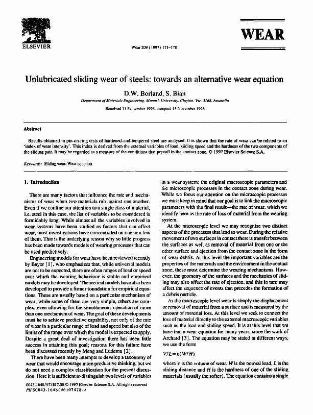
Thus we take H~ a to be equal to ( H a . g + 0 . 2 H ~ . ) . Fig. I shows the measured wear rates plotted against IO001Hm; the line plotted in the figure is the line o f best fit obtained by linear regression analysis; the variance (R 2 ) o f tbe regression line is 0.89. In the subsequent discussion we use the equiva- lent hardness, which is tabulated above.
3.2. The influence o f contact conditions on wear
While the use o f the equivalent hardness parameter has brought an improvement in the wear equation there is still scatter in the linear relationship o f Fig. I. Furthermore, this relationship is for tests at one particular load and speed; results for different loads and speeds must be included if a wear equation is to have any general applicability.
Investigation of other factors that should be included in the equation is indicated. The most fruitful way to proceed is to
Number Hpm H,,~ H,.~ ~ Load Speed c Measured wear Calculated we~ R. Measured Calculated Wk" (HV20) (HV40) W ( m s- ' ) rate VIL rate ~ V/L (ttm) Tf (°C) Tr" (°C) (Wc/H,.q)
(N) (m~rn - ' x - ' : ) (m~m - ' X -'2)
I 390 620 698 2 390 505 583 3 390 415 493 4 390 345 423 5 390 415 493 6 390 415 493 7 390 415 493 8 390 415 493 9 390 415 493
10 390 415 493 I I 390 415 493 12 390 415 493 13 340 345 413 14 340 415 483 15 3~ff} 505 573 16 340 620 688 17 490 345 443 18 490 415 513 19 490 505 603 20 490 620 718 21 598 345 465 22 598 415 535 23 598 505 625 24 598 620 740
133 133 133 133 67
II1 155 177 133 0.5 133 2 133 1.5 133 1.8 133 133 133 133 133 133 133 133 133 133 133 133
3.38 2.87 1.31 199 171 0.19 4.67 4.20 2.35 218 196 0.23 5.76 6.42 3.80 234 222 0.27 8.87 10.10 4.05 255 251 0.31 0.42 1.65 2.38 95 136 0.14 3.34 4.08 2.90 200 194 0.23
10.35 10.10 4.13 257 251 0.31 27.82 15.89 4.75 279 280 0.36 3.40 1.63 2.45 130 136 0.13
I 12.00 99.48 I. 15 400 396 0.54 8.60 25.27 270 309 0.40
94.38 57.50 365 361 0.49 7.84 10.91 256 0.32 6.52 6.79 226 0.28 4.94 4.38 198 0.23 4.20 2.95 173 0.19 7.66 8.74 242 0.30 5.46 5.77 216 0.26 3.73 3.89 191 0.22 4.03 2.72 168 0,19 8.23 7.57 233 0.29 5.04 5.18 209 0.25 3.83 3.60 186 0.21 3.52 2.57 165 0.18
• These quantities are defined in the text.
174 D. W. Borland, S. Bian / Wear 209 (1997) 171-178
I . . . . . . . . . . . . . . . . . . . . . . . . . . . . . . . . . . . . . . . . . . . . . . . . . . . . . . . . . . . . . . . . . . . . . . . . . . . . . . . . . . . . . • .................
g" iiiiiiiiiiiiiiiiiiiiiiiiiiiiiiiiiiiiiiiii iiiiiiiiiiiiiiii~,iiiiiiiiiii
4 ~ . . . . . . . . . . . . . . . . . . .
O t , e , e , i i i , i i i i
1.2 1.4 1.6 1.8 2 2.2 2.4 2.0 l o o o ~
Fig. I. The wear rates for specimens tested at I m s - ~ and 133 N, plotted against IO00/ H~. where H~ - H, w + 0.2H~,.
examine the contact conditions at the wearing interface. Since the wear particles are produced at the surface, the conditions in the contact zone are expected to have an immediate effect on wear. These conditions should include the properties of the material at the surface, the temperature, the topography oftbe surface and its state of stress.
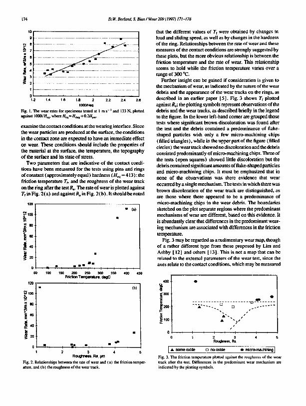
Two parameters that are indicative of the contact condi- tions have been measured for the tests using pins and rings of constant (approximately equal) hardness ( Hm = 4 ! 3 ): the friction temperature Tf, and the roughness of the wear track on the ring after the test R,. The rate of wear is plotted against Tf in Fig. 2 (a) and against Ra in Fig. 2(b ). It should be noted
{: 0
0 50
120"
---. 1oo.
x 80-
~ .
100
J i m
i I i t L 150 20O 250 30O :350
l::rlci~ Temperature, deOC
" (a)
I i
4 O O 4 5 O
120 ¸
(b)
m m I / - - L f O L
2 3 4 Roughness, Rn. p'n
t
Fig. 2. Relationships between the rate of wear and (a) the friction temper- ature, and (b) the roughness of the wear track.
that the different values of Tf were obtained by changes in load and sliding speed, as well as by changes in the hardness of the ring. Relationships between the rate of wear and these measures of the contact conditions are strongly suggested by these plots, but the more obvious relationship is between the friction temperature and the rate of wear. This relationship seems to hold while the friction temperature varies over a range of 300 °C.
Further insight can be gained if consideration is given to the mechanism of wear, as indicated by the nature of the wear debris and the appearance of the wear tracks on the rings, as described in an earlier paper [5]. Fig. 3 shows Tf plotted against Ra; the plotting symbols represent observations of the debris and the wear tracks, as described briefly in the legend to the figure. In the lower left-hand comer are grouped those tests where significant brown discoloration was found after the test and the debris contained a predominance of flake- shaped particles with only a few micro-machining chips (filled triangles ), while in the upper part of the figure (filled circles) the wear track showed no discoloration and the debris consisted predominantly of micro-machining chips. Three of the tests (open squares) showed little discoloration but the debris contained significant amounts of flake-shaped particles and micro-machining chips. It must be emphasized that in none of the observations was there evidence that wear occurred by a single mechanism. The tests in which there was brown discoloration of the wear track are distinguished, as are those where there appeared to be a predominance of micro-machining chips in the wear debris. The boundaries sketched on the plot separate regions where the predominant mechanisms of wear are different, based on this evidence. It is abundantly clear that differences in the predominant wear- ing mechanism are associated with differences in the friction temperature.
Fig. 3 may be regarded as a rudimentary wear map, though of a rather different type from those proposed by Lira and Ashby [ 12] and others [ 13]. This is not a map that can be related to the external parameters of the wear test, since the axes relate to the contact conditions, which may be measured
4 0 0 "
J
0 0
. . . . . . . . . . - - . . . . . . . . . - ~ . . . . . . . .
I I I o I i I J I 2 3 4
Rooghnass. Ra
I A ~ o~cide o no ox ide • ~ c r o - m a 'd~ntng I
Fig. 3. The friction temperature plotted against the roughness of the wear track after the test. Differences in the predominant wear mechanism are indicated by the plotting symbols.

D. W. Borland, $. Bian / Wear 2F,9 (1997) 171-178 175
but cannot be specified beforehand. The important feature of this map is that it clearly shows the existence of a change in the predominant mechanism and identifies the friction tem- perature as a parameter that might be used to differentiate between mechanisms.
When conditions are such that the friction temperature and the roughness are relatively low, the predominant mechanism of wear involves oxidation, as evidenced by the visual obser- vation of brown oxides on the wear track, as well as by the nature of the wear debris, which consisted of flakes that were agglomerates of very fine metallic and oxide particles. How- ever, when the friction temperature was above 250 °C the predominant mechanism of wear, even for low roughness, was micro-machining, evidenced by ribbons of wear debris and clean-looking wear tracks.
It is tempting to identify these wear regimes with those that were originally characterized clearly by Welsh [ 14 ] and have come to be described as 'mild oxidative" and "severe metallic" wear, with transitions TI and 7"2 identifying changes in the wear mechanism from mild (below Tt ) to severe (between Tt and 7"2) then back to mild. In We!sh's work these changes were brought about by progressive increases in load, but both of them occur under conditions that seem to be less severe than in the present experiments. It is difficult to relate Welsh' s experiments closely to those reported here, because a differ- ent configuration ( crossed cylinders) was used and the initial hardness of the two rubbing surfaces was always chosen by Welsh to be the same. We seem here to be dealing with conditions corresponding roughly to Welsh's 7"3 transition, where the thermal asymmetry of the system becomes impor- tant. Although Welsh identified this transition, in which there is 'a perturbation in the mild-wear rate at loads above T2 with the wear rates of the pin and ring diverging', he did not investigate the mechanism(s) by which wear was taking place. Certainly the change in mechanism that we have observed has nothing to do with the T~ or 7"2 transitions.
Wear is a macroscopic phenomenon, but the processes involved are microscopic in nature. The macroscopic factors (such as original hardness, load, speed) cannot affect the wear rate and wear mechanisms directly. The immediate fac- tors affecting wear are the conditions in the contact area. In other words, the rate of wear depends on the contact condi- tions which in turn depend on the combined effect of the original macroscopic parameters. This statement is analogous to saying that the hardness of steel depends on its micro- structure and the microstructure depends on the composition and heat treatment. It should be emphasized that all factors that can affect the contact conditions can also affect wear, but some of these factors (such as the hardness of the counter- surface) have usually been ignored in the published literature.
3.3. Wear rate formulae
We now turn to the question of how to describe the con- ditions in the contact zone in terms of the macroscopic par-
ameters. This is necessary if we are going to obtain a useful wear formula.
There are two ways of developing a formula to estimate the rate of wear quantitatively. The first is to assume a wear mechanism and to develop a formula based on that mecha- nism. The mechanism is, of course, chosen on the basis af observations of worn surfaces or weardebris. Archard'sadbe- sive wear model 13l, Halling's abrasive wear model [ 15] and Suh's delamination wear model [ 16] Imve all been obtained under a hypothesis of only one micro-mechanism acting. Some equations obtained in this way are simple in form and some very complex, including many parameters. In fact, while this kind of formula can be used to analyse a mechanism theoretically, it is not necessarily very useful for predicting the rate of wear in practice, for it is likely that there is no wear process that involves only one mechanism.
in the lasi ten years the emphasis in the study of wear mechanisms has changed. Researchers are now concerned not only with what happens during the wear process when a particular micro-mechanism is dominant but also with the definition of conditions under which that mechanism becomes dominant. Lim and Ashby's wear mechanism map is a reflection of this change in approach. The concept used by Lira and Ashby is that there are regions of the wear map in which a single mechanism predominates. It is implicit that changes from one predominant mechanism to another occur abruptly, but there is no fundamental reason why this should be so.
Lira and Ashby's procedure is to identify on their map blocks of dam for which the wear mechanism is the same and then to calibrate their model of the mechanism, i.e. to choose the adjustable parameters of the relevant equation to fit the measured values of the rate of wear. However, they have limited their evaluation to a number of wear mechanisms that is not necessarily complete; for example, the micro-machin- ing mechanism that we have observed is not included. The calibration procedure seems automatically to ensure that the assumed conditions are met: that only one mechanism is operating in each region.
An alternative approach to the development efa wearequa- tion is, in a certain sense, more empirical. Part of the work in the establishment of a formula is to distinguish which para- meters are more effective in determining the mechanism and rate of wear. In the present case we have identified the hard- ness of the counterface and the friction temperature as impor- tant additional vailables. We cannot, h,3wever, use the friction temperature in a wear equation because it is not an independ- ent variable; indeed, it is one of the contact conditions.
The results of tests in which the friction temperature was measured are presented in Fig. 4 as three plots, showing sep- arately how Tf varies with load, speed and H~q when the other two of these three external parameters are held constant. There seems to be a more-or-less linear relationship in each case. We therefore define a quantity that is a combination of these three parameters; this quantity would be expected to be well correlated with the friction temperature.

176 D.W. Borland, S. BianlWear209 (1997) 171-178
y"
(10
(a) (b)
f I 1 I I J
Lnn,¢l. N
20O
I 100 180
5OO
r-~o,L
, % . . . . . . . . . . . . . , , . 0.8 0.8 ". 1,2 1.4 1.6 1. 2
Spe~ , m ~
15o ~ i ~ t , i t ~ t , i ~ t t 360 4o0 45o 500 ~0 6QO ergo 700 750
Heq ( - Hr + 0.2Hp). HV
Fig. 4. The variation o f the friction temperature with ( a ) load. ( b ) sliding speed and ( c ) the equivalent hardness H ~ .
450-
J= ,00
100
00
We use the term 'index of wear intensity~ for this quantity which is defined by the equation
wk = Wv / H~
where W is the normal load, v the velocity of sliding and H~q the equivalent hardness as defined above. It has previously been noted [6] that the coefficient of friction was sensibly constant for this series of tests, so that the product Wv is proportional to the rate of doing work. As shown in Fig. 5 (Tr vs. Wk), the index of wear intensity is indeed strongly correlated with the friction temperature. The relationship appears to be linear: the line plotted in Fig. 5 represents the line of best fit obtained by linear regression. Calculated results ere shown in Table 1.
We now seek a relationship between Wk and the rate of wear. Fig. 6 shows this relationship graphically, including all the results in Table 1. It is evident that some form of powez law is required to fit an equation to these data. The amount of scarer and the relative paucity of data for high values of W k do not encourage exhaustive efforts at curve firing, but the curve drawn in Fig. 6, which corresponds to the equation
V/L=0.414 exp( 10.16Wk)
is indicative of the trend. More interestingly, we can distin- guish in this plot the regions where different mechanisms of wear predominate. These regions are indicated in Fig. 6. As has been discussed above, and in earlier publications [5,6], there are two mechanisms that have been identified for the conditions of this study, neither of them belonging to the conventional classification schemes on which Lim and Ashby's map is based.
I 2.2
? o1.+o
~1oo
re
0
wi ~ = 0414mlp(10 '[~/~) I
i . . . . . . ! :L . . . . ~ - " I . /
1 I I I . - - , r I i I L I L I
0.1 0.2 0.3 0.4 O.S O.e Irtdex of Wear In tense, V~1<
Fig. 6. The wear rate plotted agains t the index o f wear intensity W k.
The first of these, characterized by oxide films on the worn surfaces and flake-like debris, is a mechanism involving the presence of a third body, which we have described as a tribo- layer. The presence of such layers has often been reported in
200
0 0.2 0.4 0.6 Index of Wmt Ir~msity, Wk
Fig. 5. The friction temperature plotted agains t the index o f wear intensity w~.

D. W. Borland, S. Bian / Wear 209 (1997 ) 171-178 1"/7
studies of sliding wear but their structure and the exact con- ditions under which they form is net well documented. The second, which amounts to 'abrasive ' wear, with the removal o f debris by the machining action of protuberances on the surface o f the ring, is well known as a mechanism of wear [ 17 ] but the conditions in a pin-on-ring test under which this mechanism may occur are again not well defined.
Thus it is by no means clear how the results discussed here should be related to those used in the construction of Lira and Ashby ' s map. Nevertheless the index o f wear intensity, as proposed here, does seem to provide a useful perspective on some aspects o f wearing behaviour as displayed in pin-on- ring tests and, presumably, in similar configurations such as pin-on-disc where the temperatures o f the two sliding com- ponents may differ appreciably. According to our results the value o f Wk can be used to characterize three regimes in the range that has been explored in this study: i . when Wk < 0.23, the rate of wear is low, less than 5 X
10- ~2 m 3 m - t and the debris is predominantly flake like, generated from the tribo-layer, with oxide films on the worn surfaces;
2. if 0.23 < Wk < 0.35, the rate o f wear is between 5 and i O x !0 -12 m 3 m - t , cutting-type debris appears more frequently and there is little sign o f oxide films;
3. when Wk > 0.35, cutting-type debris predominates and the rate o f wear increases rapidly with W k.
These results have been obtained for relatively hard steel pins sliding against steel r ings o f comparable hardness. Unfortunately there seem to be no reports in the literature that are strictly comparable. The main difference between our treatment o f the data and that used in other studies o f dry sliding wear is that we have attempted to take into account the behaviour o f the wearing system, not just the effect of load or speed or some other single parameter. Lira and Ashby [ 12] have noted that both the applied load and the speed are important: we have suggested a parameter Wk that takes in both o f these variables as well as the hardness o f the coun- terface. We believe that this will be a more useful parameter in the quantitative study o f wear ing processes because it takes into account the conditions in the contact zone, albeit in an indirect way because those conditions cannot be exactly spec- ified in terms o f the external parameter : o f the system. These results have been obtained using a particular testing config- uration, over a limited range o f conditions, but they provide a perspective that should be investigated over a wider range and for other configurations.
4. Conc lus ions
1. The wear mechanisms that have been observed for quenched-and-tempered steel pins sliding against simi- larly treated rings are not consistent with any existing
models of wearing mechanisms for the unlubricated slid- ing of steel on steel.
2. In wear testing the hardness of both o f the rubbing com- ponents is important, at least under some conditions such as those that have been used in these investigations. An "equivalent hardness ' parameter, H~q=H,i . l+CHp~n, is proposed, where C is a constant. It is suggested that the use o f H~q as a measure o f the mechanical properties takes into account the properties o f both members o f the friction pair.
3. The conditions in the contact zone are important in deter- mining the mechanisms and therefore the rate o f wear. It seems that temperature is the most important determinant of these conditions.
4. An ' index ofwear in tens i ty ' , Wk = W v / H , ~ , c a n b e d e r i v e d
from the external variables. It is related to the friction temperature and can be used as a measure o f conditions in the contact zone.
5. For pin-on-ring wear r~.sts an empirical formula has been derived that expresses the rate o f wear in terms o f the index of wear intensity.
References
[ I ] R.G. Bayer. Mechanical Wear Prediction and Prevention, Marcel Dekker, New York, 1994, p. 321.
[ 2 ] H.C. Meng and K.C. Ludema, Wear models and predictive equations: their form and content, Wear. 181-183 (1995) 443--457.
[ 3 ] J.F. Archard. Contact and rubbing of flat surfaces. J. Appl. Phys.. 24 (1953) 981-988.
[4] D.A. Rigney, The roles of hardness in the sliding bchavionr of materials. Wea., 175 (1994) 63.-69.
[ 5 ] S. Bian. S. Maj and D.W. Borland, The unlubdcated sliding wear of steels: the role of the hardness of the friction pair, Wear, 166 ( 1993 ) I-5.
[6] S. Bian, S. Maj and D.W. Boriand, The unlubricated sliding wear of steels: the contact conditions in the sliding zone. J. Testing Eval., 24 (I) (1996) 12-19.
17 ] J. Kalon~k, D.M. Fegredo and E.E. Laufer, The wear ~sistane¢ and worn metallography of pearlite, bainite and tempered martensite rail steel microstractures of high hardness, Wear. 105, ( 1985 ) 199-222.
[ 8 ] M. Godet, Third bodies in tribology, Wear, 136 (1990) 29.-45. [9] S.L. Rice and S.F. Wayne, Specimen material reversal in pin-on-disc
tribotesting, Wear. 88 (t983) 85-92. 1101 H. Kranse and W. Tackenherg, The influence of hardness difference
on the frictional and wear hehavionr of steel/copper alloy pairs in plane sliding friction under mixed friction conditions, Wear, 64 ( 1980 ) 291-302.
[ 11 ] T. Akagaki and D.A. Rigney. Sliding friction and wear of metals in vacuum, Wear, 149 ( 1991 ) 353-374.
[ 12] S.C. Lira and M.F. Ashby, Wear mechanism maps. Acta Metall., 35 (1987) 1-24.
[ 13l L. Rapopon, The competing wear mechanisms and wear maps for steels, Wear, 181-183 (1995) 280--289.
I 14 [ N.C. Welsh, The dry wear of steels parts ! and II. Proc. R. Soc. London. Ser. A. 257 (1965) 31-70.
[ 15] R.D. Arnell. P.B. Davies, J. Hailing and T.L. Whomes, Tribology Principles and Design Applications, Macmillan, London, 1991, Chapter 3.

178
i 161 N.P. Suh, Tribophysics, Prentice-Hall, Englcwood Cliffs, NJ, 1986. [ 17 ] IL Kato, Micro-mechanisms of wear--wear modes, Wear, 153 (1992)
277-295.
Biographies
D.W. Borland graduated BMetE from Melbourne University in 1954 and Phi) from Sheffield University in 1966. He was Senior Lecturer in the Department of Metallurgy, University of Melbourne from 1966 to 1982. Following closure of that department he led the Materials Group, Department of
D. W. Borland. S. Bian / Wear 209 ~ 1997) 171-178
Mechanical and Manufacturing Engineering, until his retire- ment in 1992. He is now a Research Associate at Monash University.
S. Bian studied Welding Engineering in the Department of Material Engineering, Jilin University of Technology, grad- uating BE in 1982. Following a successful Master of Engi- neering program at the Material and Technology Research Institute, Beijing he worked as a research engineer in that Institute from 1985 to 1988. He graduated PhD from Mel- bourne University in 1994 and is currently seeking appropri- ate employment.


![Influence of oxide films on the wear of steels · fs T%l era] WearojSteels 27 1 Thewearingsurfacesofbothspecimenswerebrightwithnotraceof film;theywerealsoveryroughandthewearofthespecimentem](https://img.dokumen.tips/doc/110x75/5f0f02517e708231d44208eb/influence-of-oxide-films-on-the-wear-of-steels-fs-tl-era-wearojsteels-27-1-thewearingsurfacesofbothspecimenswerebrightwithnotraceof.jpg)