Embed Size (px)
Citation preview
Unlicensed Wireless Multipoint System in Sacramento Metro
Motorola Canopy

The Problem
• No broadband communication available to four cameras in the Sacramento Metro Area.
• Date Line June 2004

The Options
• POTS line• Microwave Wireless link• GPRS Wireless link

Feasibility Requirements
• Permission to mount radios on DGS Tower• Permission to mount radios on TMC Tower• Time time to receive tower permissions• Line of Sight• RF Environment analysis• Costs

The Choice
• Multi-Point Microwave link to central communication tower and a separate backhaul link to D3 RTMC
• Motorola Canopy 5.7 GHz U-NII Band, 6 channels at 20MHz
• Deployed World Wide• Proven reliability with ISP and Carriers

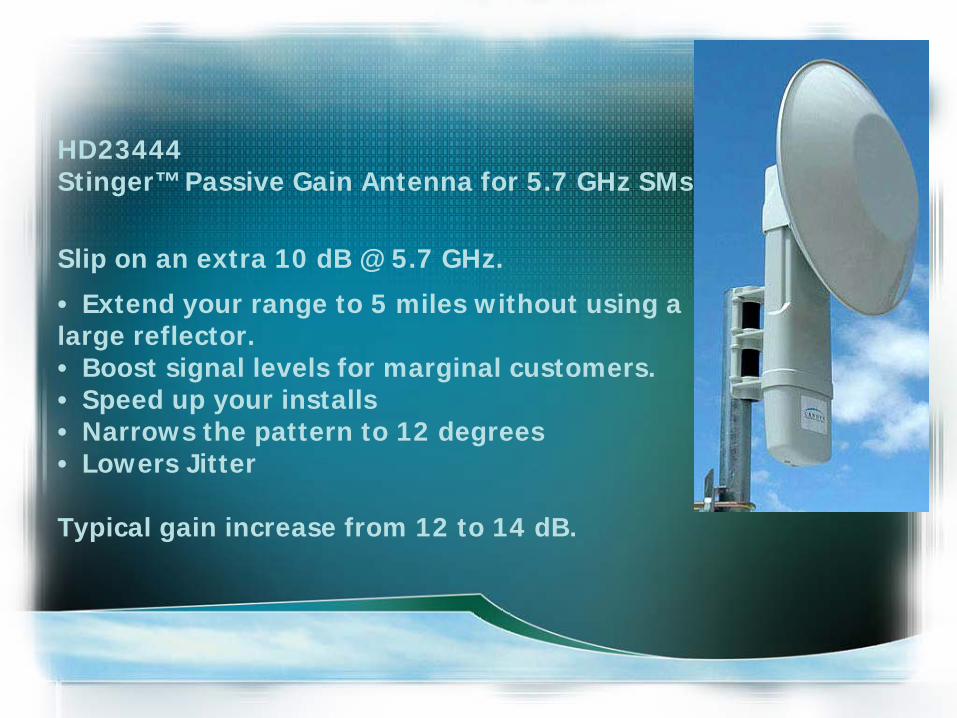
HD23444Stinger™ Passive Gain Antenna for 5.7 GHz SMs
Slip on an extra 10 dB @ 5.7 GHz.
• Extend your range to 5 miles without using a large reflector.• Boost signal levels for marginal customers. • Speed up your installs • Narrows the pattern to 12 degrees • Lowers Jitter
Typical gain increase from 12 to 14 dB.

Controlling Interference: The Canopy Approach
Interference in a PMP BWA network,either self-induced or external, isgenerally an issue more for the Access Point (AP) than for SubscriberModules (SM).
At the AP, typically antennas with much wider angles are used so thatthey may communicate with many SMs spread over a given geography..
Beam widths for these devices can range from 45 to 360 degrees. Thewider the angle, the more potential there exists for either self-interference or external interference.
Because a single AP supports dozens, if not hundreds, of end users orcustomers, interference at this stage in the network deployment canhave a large impact.

Controlling Interference Continued
The issue in BWA networks designed to support data or IP-based traffic can be even more insidious.
In this instance, a very small amount of RF interference canhave a huge performance impact on the network throughput: insome instances three to four percent RF interference can resultin a 40 percent reduction actual end-to-end data rates.
The problem of interference in PTP networks operating in thelicense exempt bands, while not as severe as that encounteredin PMP networks(due to the use of highly directional antennas atboth ends),must still be addressed.

Modulation and the C/I ratioAt the most fundamental level, an interfering RF source disruptsthe digital transmission by making it too difficult for the receivingstation to "decode" the signal.
How much noise or interference a digital RF transmission cantolerate depends on the modulation used.
Fundamentally, modulation is the method whereby zeros and onesare communicated by varying one of three aspects of a radiosignal.
The three portions of an RF signal that can be changed ormodulated are phase, frequency, and amplitude. Shifting theproperties of any of these parameters can be used tocommunicate different "states." These states, in turn, aretranslated to zeros and ones for binary communications.

Binary Frequency Shift Keying BFSK
For example, with frequency modulation, if the sine wave is atfrequency one, it is decoded as a zero. If the sine wave isshifted slightly to frequency two, this is decoded as a one.
This type of modulation is referred to as Binary FSK (BFSK), orFrequency Shift Keying. In this example, a system must only beable to tell the difference between one of two states or phases.
More complex modulations, such as 16QAM (quadratureamplitude modulation), attempt to differentiate among 16different possible states of an incoming signal.

Advantage of BFSK
The ability of a receiving station to decode an incoming signal atthe most basic physical layer is dependent on a factor called the"carrier to interference ratio," or C/I.
This fancy-sounding term means exactly what it says: how strongthe desired signal (the carrier) is relative to the unwanted signals(the interference).
C/I ratios are based primarily on the modulation used, with morecomplex modulations requiring higher C/I numbers than morerobust modulations, such as BFSK.

More BFSK
The Canopy product employs BFSK for modulation. With thismodulation the C/I ratio necessary to operate properly withan error rate of 1x 10-4 bits per second is only 3dB;
i.e. the wanted signal need be only 3dB higher in power thanthe unwanted interferers.
A system operating with 16 QAM at these levels wouldrequire a C/I ratio ofroughly 12 to 14dB.
Putting this into perspective, with every 3dB of additionalsignal strength, the power of a signal is doubled.

This means that the Canopy system, with its C/I ratio of 3dB,can tolerate an interfering signal that is many times morepowerful than a 16QAM system and still operate at the specifiederror rate.
Canopy system employing BFSK modulation will toleratesubstantially higher levels of interference before thecommunication stream becomes impacted. All other PHY layertechniques are designed to improve this most fundamentalmeasurement of network robustness and operationaleffectiveness by sustaining the necessary C/I level.
Still More BFSK

Antenna Front-To-Back RatioThe front-to-back ratio of an AP antenna indicates how much of anincoming signal will be absorbed coming into the front of theantenna as compared to how much of a signal arriving at the backof the antenna is absorbed.
When deploying networks in a cellular topology, the performance ofthe antenna in rejecting unwanted signals from behind is animportant feature.
The Canopy system, with its integrated antennas at the AP, has afront-to-back ratio of 20dB.
Coupled with the excellent C/I ratio, this means a Canopy APreceiving a signal at threshold (the weakest signal it can still detect)can be hit with an interfering signal from behind, either internal orexternal, on the order of -60dBm and still support connections at anacceptable error rate.

Time Division Duplexing Synchronization
BWA networks that use Time Division Duplexing for separatingupstream and downstream communications are ideally suited forasymmetric traffic, such as data.
The ability to adjust the amount of bandwidth dedicated forupstream and downstream communications without changinghardware is a powerful feature.
TDD systems operate by transmitting downstream (from the AP tothe SM) for a period of time -- 1ms for example. Following a shortguard time, the SMs then transmit on the same frequency in theupstream.

TDD Continued
For a cell site with more than one radio operating in TDD mode, itis important that all the sectors of the cell transmit and receive atprecisely the same time.
Otherwise, if sector 1 is transmitting when sector 2 is receiving,sector 2's incoming transmission can be interfered with even ifthey are on different frequency channels because the sector 1signal is so close it is strong enough to "flood" or overwhelm theelectronics in sector 2.

More TDDWhen deploying a TDD system in a cellular topology, it is desirable tobe able to use the same frequency in each cell site even thoughthose cell sites are possibly several miles away.
This means sector 1 from AP A may interfere with sector 1 of AP B.To avoid this inter-cellular synchronization is required, making surethat all the sectors in all the cell sites are properly timed andsynchronized in terms of downstream and upstreamcommunications.
With the Canopy system, designed for large scale, dense networkdeployments, TDD synchronization is a critical requirement. This hasbeen solved with the use of a GPS signal. These precise satellitesignals are used for timing and, ultimately, transmit/receivesynchronization, thus tying all sectors in a Canopy network to thesame "clock."

Dealing W/Interference- The MAC LayerMAC - Medium Access Control
MAC Layer- That layer of a distributed communication system concerned with the control access to a medium that is shared between two or more entitiesThe original data, an IP packet datagram, for example, is segmented intopackets that fit into a radio data packet (RDP).
Despite all the best deployment design and use of the extremely robustCanopy system, there will be instances where interference will overcomethese measures and corrupt a MAC frame or a portion of a MAC frame.
When this happens, the corrupted data must be sent again. If the MACframe is designed for large RDPs on the order of several hundred bytes,the entire slot must be re-transmitted even if only a small amount of thispacket is damaged

The MAC Layer ContinuedThe impact on network throughput as a result can be large, with afew bytes in error causing hundreds of bytes to be re-sent.
Canopy solves this problem by using RDPs sized at 64 bytes. Withthis smaller RDP size, the re-transmission can be contained to onlythose bytes that were damaged, thus avoiding the re-send of largechunks of valid data.
The 64-byte slot could have been made even smaller, but as RDPsize decreases, the slot header which is fixed becomes a moresignificant portion of the packet data, hence increasing the MAClayer overhead.
In addition the 64-byte slot is ideally sized for handling the TCPacknowledgements sent for most IP packets.

The Problem With TCP
TCP/IP networks were designed to operate in the wired world whereinterference was assumed to be negligible.
The protocol design calls for a positive acknowledgement sent fromthe receiving station to the sending station for every IP packet sentout.
If the sending station does not receive the TCP ACK in a certainamount of time, it is assumed that the cause was congestion of thenetwork - not an error resulting from transmission impediments.
When encountering congestion, TCP responds by dramaticallyslowing down the transmission and then increasing transmissionspeed slowly.

Automatic Retransmission RequestThe Canopy system solves the problem with a feature calledAutomatic Retransmission reQuest or ARQ.
ARQ actually inspects the RDPs that come into the receiving SMand looks for errors. If an error is detected, the SM (or AP) will senda request to the sending entity to re-send the RDP.
All of this is accomplished two layers below TCP in the protocolstack. The net effect is that as far as TCP is concerned, it neverreceives a packet of data with an error as a result of the wirelessportion of the network.
This prevents TCP from invoking the slow start algorithm, keepingthe end-to-end data rates at the peak or just slightly below peakoperational rates.
IEEE 802.11 Transmit Contention
The IEEE 802.11 standard operates in what is referred to as adistributed control manner. This means that each SM has theability to send a packet at its own discretion.
Typically in this scenario the SM will "listen," and if it does nothear any transmissions, it will assume the channel is clearand send its data.
The problem arises if the sending SM cannot hear other SMs.
In this instance, two or more SMs may send a packet at thesame time, corrupting both and causing a retransmission.Interference is also a culprit in blocking SMs from hearingeach other with the same effect

Centralized Transmission Control
Canopy solves this contention problem by implementing ademand contention access scheme where the AP controls alltransmissions in the sector, both upstream and downstream.
An SM will only send its data when allowed.
If an SM's request to send data is interfered with, it will waitand try again, but at no point will it ever transmit into theuplink data channel until it is permitted by the AP.

Expectations
• To stream video at a bandwidth of 150K bps.• High Reliability 99.9999% ?

Reliability• The simplest definition of reliability is quality over time.
Since time is involved in reliability, it is often measured by a rate. Just as quality is usually measured in terms of rejects (or un-quality), reliability is measured in terms of failures (or un-reliability). (from NASA website)
• Reliability is a network’s ability to perform a designated set of functions under certain conditions at specified operational times.
• Availability is a network’s ability to perform its functions at any given instant under certain conditions. Average availability is a function of how often something fails and how long it takes to recover from failure.

The next step should be to decide on the degree of reliability or availability which the system is required to yield.
Most non-technical people posed with such a question would probably respond with answers like: "The best possible, " "It must always be available when needed," or possibly "Communications are vital to be my business and no service interruptions can be tolerated."
Unfortunately, these answers are of little value or help to the microwave system designer who requires a specific numeric value upon which to base the design.
The appropriate selection of this value is of paramount importance, since it will affect many subsequent design decisions and the over-all cost of the system.
Preliminary Planning

•Operating frequency band
•Maximum path length
•The need for diversity
•Equipment failure protection
•Antenna size
•Transmitter output power
•Equipment selection
•The required traffic capacity
•The length of the path
•Frequency congestion in the area
•Weather conditions
RF Design Criteria

Reliability Table
Reliability % Outage time % Outage time per year
0 100 8760 hours
90 10 876 hours
98 2 175.2 hours
99 1 87.6 hours
99.9 0.1 8.8 hours
99.95 0.05 4.4 hours
99.99 0.01 53 minutes
99.995 0.005 26 minutes
99.999 0.001 5 minutes
99.9999 0.0001 32 seconds

The reliability Table shows the relationship between reliability and outage time, but it is almost impossible to predict the duration and frequency of each individual outage, which will contribute to this total value.
Further, the outage time will be composed of two different reliability figures.
Equipment malfunctions can be expected to be relatively rare, particularly if standby assemblies are furnished, but may be of long duration. If the microwave station is remotely located, it may take an hour or more to dispatch a technician and remedy the fault.
Service interruptions due to propagation conditions will be more frequent but of short duration—typically a few seconds. The permissible outage time will affect such factors as:
Reliability Continued

Reliability Calculations (Norwood)
( ) %9888.99109126.1111100% 6 =×−×= −R
Unreliability= Outage Probability = 1036 10105.2
F
DfbaUndp−
− ××××××=
a = Terrain Factor = 1 (for average terrain, with some roughness)b = Climate Factor = 0.25 (for nomal interior temperate or northern areas)f = frequency in GHzD = Path length in milesF = Fade Margin in dB
6107
36 109126.111104.57.5105.225.01 −−
− ×=××××××=NorwoodUndp
The percent reliability is computed from the outage probability = ( )UndpR −×= 1100%
min86.58109126.111 6024365.25 Year
Outage 6 =××××= −

One important point to note here is that the antenna gain is reciprocal, i.e., the antenna gain can be added to the wireless device at either end to increase the overall link budget. For example, a wireless system with a 10 dBi antenna on the transmitter and a 2 dBi antenna on the receiver will have the same range as a system with a 4 dBi antenna the transmitter and an 8 dBi antenna on the receiver, everything else being equal. Therefore, adding a high gain antenna allows a device not only to transmit signals farther, but also to receive weaker signals.
Reciprocity In Antenna Design

Calculating Rx Signal Level

Rx Bryte Bend = 23dBm + 7dBi - 0 + 10dBi(stinger) - 119dB(2.4miles) + 7dBi - 0= -72dB
Rx Norwood = 23dBm + 7dBi - 0 + 10dBi(stinger) - 126dB(2.4miles) + 7dBi - 0= -79dB
Rx Northgate = 23dBm + 7dBi - 0 + 10dBi(stinger) - 122dB(2.4miles) + 7dBi - 0= -75dB
Rx Raley = 23dBm + 7dBi - 0 + 10dBi(stinger) - 126dB(2.4miles) + 7dBi - 0= -79dB
Signal Level Calculations
Link Budget =TXpwr +TXgain + Rxgain + Rxgain - (-Rxsensitivity) - FM = 23dBm + 7dBi + 10dBi(stinger) + 7dBi - (-86dB) -3dB= 130dB

Fade Margin Calculations
FM Bryte Bend = -72dB - (-86dB) = 14dB
FM Northgate = -75dB - (-86dB) = 11dB
FM Norwood = -79dB - (-86dB) = 7dB
FM Norwood = -79dB - (-86dB) = 7dB
Typically, broadband wireless systems recommend a fade margin of 10dB. The Canopy system is unique in being more tolerant of lower fade margin that other systems, and can operate reliably with a 3dB fade margin.

Norwood Fresnel Zone Calculation
( ) ftmiGHz
mimiF 164.57.5
1.53.0721 =××
=
F1 = The first Fresnel zone radius in feetD = the total path length in milesd1 = the distance from one end-point to the point being considered in milesd2 = D - d1 in milesf = Frequency in GHz
( )DfddF
××
=21721

Jitter

Assumptions
• Bercut tower radio mounting height 220ft• Spectral Density• Line of Sight was “good enough”


Motorola’s AnalysisBob Simmons (Senior Account Manager) wrote the following:
The two Access Points (AP) located at the Bercut site will facilitate the connectionsto all four of the camera sites, with on one AP providing connections for the Northgate,Norwood, and Raley sites (as these sites appear to be within a 60 degree sector), andthe other AP facilitating the connection to the Bryte Bend Bridge.
The Cluster Management Module (CMM) will provide the clocking for all the radios in thisapplication.
I have also included 2 Ethernet surge suppressors at each remote locationwith the assumption that there will be a high level of radio activity in the area.
If you feel that there is a minimal amount of RF interference at these locations, you may choose to install a single surge suppression unit at the bottom of the Ethernet cable runon the tower.

Motorola Caveats With regards to the path analysis:
I wanted to mention that the path analysis information noted does not make allowances for any man-made or vegetative obstacles which may be in the transmission path.
I also want to note that as the antenna heights at each of the remote camera sites are relatively low, any man-made or vegetative obstacles which may be in close proximity to the remote camera sites may cause the link to be unreliable.
Please be advised that the Canopy units require a line of sight transmission path (which includes a minimum requirement for an 80% Fresnel Zone clearance for the same transmission path).

Actual Conditions August 2006
The DGS permit was restricted to the 135 ft level, not the 220ft as requested.
It was decided to populate the CMM with five radios. One per SM in case we needed to try a point-to-point approach. And One extra for future use.
The 10dBi Stinger antenna was used over the 18dBi Dish to avoid potentialconflict with Structures.
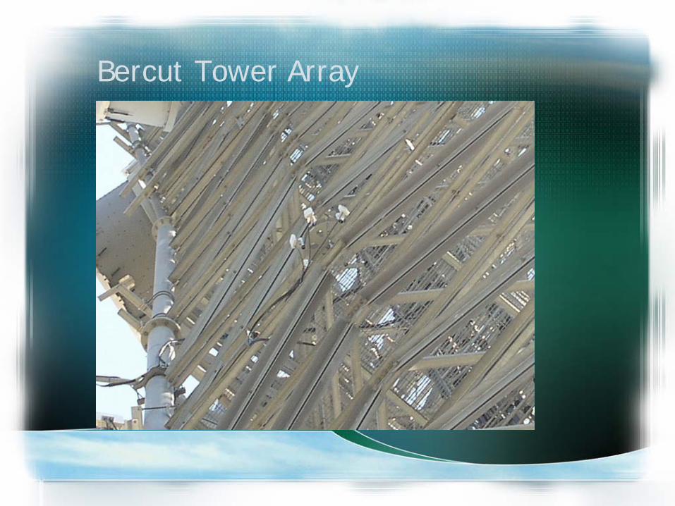
Bercut Tower Array

Bercut Tower Array 2

Northgate Results
The site at Northgate came up without issue and the received signalstrength at the SM is -75dB
This yields an actual fade margin of 86dB - 75 dB = 11dB
The calculated fade margin was -75dB

Northgate Path

Northgate View From Cam to Bercut

Northgate SM

Bryte Bend ResultsThe site at Bryte Bend came up with issues and the received signalstrength at the SM was -91dB
This yields an actual fade margin of 86dB - 91 dB = -5dB
It was determined that there was tree inclusion in the Fresnel Zone.
The SM was elevated 10 ft with a pole-to-pole extension and the Rxsignal strength is now a measured 72dB.
This yields an actual fade margin of 86dB - 72 dB = 14dBThe calculated fade margin was -72dB

Bryte Bend Path

Bryte Bend Cam to Bercut

Bryte Bend SM
Norwood Results
The site at Norwood did not come up due to low -90dBm Rx signal
This yields an actual fade margin of 86dB - 90 dB = -4dB
Then came Fall/Winter 2006 and the link came up! The Rx signal is now -80dBm
This yields an actual fade margin of 86dB - 80 dB = 6dB
Then came spring 2007, Rx back down to 90dBmThe calculated fade margin was -70dB

Norwood Path

Norwood Cam to Bercut

Norwood SM

Raley Results
The site at Raley did not come up due to low Rx signal

Raley Path

Raley SM


Lessons Learned
• Nail down design variables prior to design (ie: Tower height availability)
• Perform site survey(spectral analysis of RF frequencies and line-of-sight determination) prior to project design.
• The more directional the antenna the better• Choose licensed or licensed public safety band
frequencies

Fixing Norwood & Raley
• Add a Stinger antenna to the AP• Replace Stinger with a Dish at SM• Raise the SM height • Prune a tree