Embed Size (px)
Citation preview

UNIVERSITY OF NORTHERN BRITISH COLUMBIA Purchasing Division 3333 University Way Prince George, B.C. Canada V2N 4Z9 Tel: (250) 960-5500 Fax: (250) 960-5507
RFP15-1548
ADDENDUM #1
Date: September 25, 2015
Re: RFP15-1548 – Boiler Replacement (BMO Building)
SITE VISIT CLARIFICATIONS:
1. Flushing and Inhibitor: Debbie Bisson of Nalco Canada Co. has recommended the boiler manufacturer’s installation cleaning procedure be followed. For the existing piping Debbie is looking into an appropriate cleaning dispersant/purging compound. For the treatment we will be using Nalco TRAC108. Debbie has agreed to receive calls regarding this and will assist with questions. The University will be working with Debbie and the successful vendor during the flush and treatment of the system.
Debbie Bisson, Nalco Canada Co. Ph: 250-649-6641.
2. The Contractor is not required to post a bond for this project.
3. If other boilers are to be considered they must meet the following requirements; 150,000
Btu condensing, 3” venting, eligible for Fortis rebate. The alternate boiler shall have capabilities to control the heating system as provided by Prism Engineering
4. The current mixing valve is not to be replaced, unless deemed necessary by the University. The installer is required to review the enclosed manual for the boilers for wiring and programming the controllers on the three boilers. With a controller on one boiler as the master controller and the controllers on the other two boilers as slaves, the boiler controller can provide all of the control functions and Tekmar controller is not required. The boilers are supplied with an outdoor sensor which needs to be installed. It resets the supply water temperature with outdoor temperature and also shuts off the boilers in warm weather. The master controller sequences the three boilers based on heating demand. A programmable room thermostat is required to start the boiler plant. It is to be located in a perimeter office and set 1° to 2° C lower than the setting for the AHU serving the area the office is located in. Night set back temperature should also be set 1° to2° C lower than the night set back temperature for AHU. The perimeter office chosen can be in close proximity of the boiler room provided the intended purpose of the thermostat is met.

Call for heat from the programmable room thermostat starts the boiler pump(s) and system pumps, QQ-P1 and QQ-P2, and fires the boiler(s) to satisfy the heating demand. A manual alternate switch is required so the system pumps, QQ-P1 and QQ-P2 can be manually alternated once a month as only one system pump can be started by the controller. The two system pumps are variable speed and shall be set for constant pressure so the speed will vary as the two way valves on the radiation open/close. The existing three way valve is not required and shall be left in the open position. Please see attached documents.
5. Asbestos may be encountered if removing walls. As the removal of walls is not anticipated, this should not be an issue.
6. BX is acceptable, conduit will not be required. All routing is to follow current codes and demonstrate quality workmanship..
Thank you,
Sandra Shelke, Purchasing Agent University of Northern British Columbia

Installation and Operation Instructions Document 1252B
H23
5520
0B
WARNINGIf the information in this manual is not followed exactly, a fire or explosion may result causing property damage, personal injury or loss of life.
Do not store or use gasoline or other flammable vapors and liquids in the vicinity of this or any other appliance.
WHAT TO DO IF YOU SMELL GAS• Do not try to light any appliance.• Do not touch any electrical switch; do not
use any phone in your building.• Immediately call your gas supplier from a
nearby phone. Follow the gas supplier’s instructions.
• If you cannot reach your gas supplier, call the fire department.
Installation and service must be performed by a qualified installer, service agency, or gas supplier.
FOR YOUR SAFETY: This product must be installed and serviced by a professional service technician, qualified in hot water boiler and heater installation and maintenance. Improper installation and/or operation could create carbon monoxide gas in flue gases which could cause serious injury, property damage, or death. Improper installation and/or operation will void the warranty.
AVERTISSEMENTAssurez-vous de bien suivres les instructions données dans cette notice pour réduire au minimum le risque d’incendie ou d’explosion ou pour éviter tout dommage matériel, toute blessure ou la mort.
Ne pas entreposer ni utiliser d’essence ni d’autres vapeurs ou liquides inflammables dans le voisinage de cet appareil ou de tout autre appareil.QUE FAIRE SI VOUS SENTEZ UNE ODEUR DE GAZ:
• Ne pas tenter d’allumer d’appareils.• Ne touchez à aucun interrupteur. Ne pas vous
servir des téléphones dansle bâtiment où vous vous trouvez.
• Appelez immédiatement votre fournisseur de gaz depuis un voisin. Suivez les instructions du fournisseur.
• Si vous ne pouvez rejoindre le fournisseur de gaz, appelez le sservice des incendies.
L’installation et l’entretien doivent être assurés par un installateur ou un service d’entretien qualifié ou par le fournisseur de gaz.
Installation and OperationInstructions for
NEOTHERM ®
Modulating Boiler Model NTHSizes 080–850 MBTU/h
Water Heater Model NTVSizes 150–850 MBTU/h

LAARS Heating Systems
Section 1 - General Information1.1 Introduction ....................................................... 11.2 ModelIdentification ........................................... 11.3 ApplianceOverview .......................................... 21.4 Warranty ........................................................... 61.5 Unpacking ......................................................... 61.6 Dimensions ....................................................... 6
Section 2 -Locating the Appliance2.1 GeneralInformation .......................................... 82.2 LocatingApplianceforCorrectVentDistance fromOutsideWallorRoofTermination ............. 8
Section 3 -Venting and Combustion Air3.1 CombustionAir ................................................. 93.2 Venting ............................................................ 103.3 LocatingVent&CombustionAirTerminals ..... 123.4 CommonVentTest ......................................... 15
Section 4 -Gas Supply and Piping4.1 GasSupplyandPiping ................................... 15
Section 5 -Pump Requirements5.1 NeoThermBoilerFlowand HeadRequirements ........................................ 165.2 NeoThermWaterHeater FlowandHeadRequirements ........................ 16
Section 6A -Water Connections - NTH Boiler6A.1 NTHSystemPiping:HotSupply Connections .................................................... 176A.2 NTHColdWaterMake-Up .............................. 176A.3 CondensateDrain ........................................... 186A.4 FreezeProtection ........................................... 186A.5 NTHSuggestedPipingSchematics ............... 186A.6 RecognizedChemicals ................................... 18
Section 6B -Water Connections - NTV Water Heater6B.1 NTVWaterQuality .......................................... 266B.2 PipingRequirements ...................................... 266B.3 ColdWaterMake-Up ...................................... 276B.4 CondensateDrain ........................................... 276B.5 FreezeProtection ........................................... 276B.6 NTVSuggestedPipingSchematics ................ 276B.7 NTVSuggestedPumps .................................. 27
Section 7-The User Interface 7.1 AbouttheUserInterface ................................. 30 7.2 NavigatingthroughtheUserInterface ............ 307.3 TheHomeDisplay .......................................... 317.4 CustomizingyourHomeDisplay .................... 317.5 Entering/ChangingControlSettings ............... 31
Section 8A -Quick Start Menu8A.1 QuickStartMenu ............................................ 35
Section 8B -Basic Installation and Wiring8B.1 InstallationWarnings ...................................... 368B.2 MainPowerConnections ................................ 378B.3 PumpConnectionsandOperation ................. 37
Section 8C -Detailed Setup Instructions and Diagrams8C.1 24VACTransformerwithIntegral CircuitBreaker ................................................ 388C.2 HydronicHeatingDemand ............................. 388C.3 Anti-Short-Cycle ............................................. 388C.4 OutdoorAirTemperatureSensor .................... 388C.5 OutdoorReset ................................................ 388C.6 WarmWeatherShutdown ............................... 408C.7 DomesticHotWater........................................ 408C.8 CascadingLead/LagOperation ..................... 428C.9 HydronicHeatingUsingExternal ModulationControl ......................................... 458C.10 OptionalFieldConnections ............................ 468C.11 Connectionstoa BuildingAutomationSystem ........................... 468C.12 LadderandWiringDiagrams .......................... 47
Table of Contents
i

NEOTHERM Boilers and Water Heaters
Section 9 - First Start-Up and Adjustment Instructions 9.1 FillingtheBoilerSystem ................................. 509.2 FirstOperation ................................................ 509.3 AdjustingtheDifferentialand ManifoldPressure ........................................... 519.4 ShuttingDowntheNeoThermUnit ................. 539.5 RestartingtheNeoThermUnit ........................ 53
Section 10 - Maintenance10.1 SystemMaintenance ...................................... 5410.2 ApplianceMaintenanceandComponent Description ...................................................... 5410.3 GasConversion .............................................. 57
Section 11 - Operating Details and Troubleshooting11.1 NormalStartupandInitialization ..................... 5811.2 SequenceofOperation .................................. 5811.3 ModulationControl ......................................... 5811.4 PumpControl .................................................. 5811.5 Anti-Short-Cycle ............................................. 5911.6 TemperatureSensors ..................................... 5911.7 Diagnostics ..................................................... 5911.8 ErrorCodes .................................................... 59
Section 12 -Replacement Parts13.1 GeneralInformation ........................................ 6013.2 PartsList ......................................................... 60
Appendices -AppendixA-SoftwareControlFunctions .................... 71AppendixB-ErrorMessages...................................... 77
ii

LAARS Heating Systems

Page 1NEOTHERM Boilers and Water Heaters
Section 1 -GENERAL INFORMATION
WARNINGNeoTherm units must be installed in accordance with the procedures detailed in this manual, or the LAARS Heating Systems warranty will be voided. The installation must conform to the requirements of the local jurisdiction having authority, and, in the United States, to the latest edition of the National Fuel Gas Code, ANSI Z223.1/NFPA54. In Canada, the installation must conform to the latest edition of CSA B149.1 Natural Gas and Propane Gas Installation Code, and/or local codes. Where required by the authority having jurisdiction, the installation of NeoTherm boilers must conform to the Standard for Controls and Safety Devices for Automatically Fired Boilers, ANSI/ASME CSD-1. Any modifications to the boiler, its gas controls, or wiring may void the warranty. If field conditions require modifications, consult the factory representative before initiating such modifications.
1.1 IntroductionThis manual provides information necessary for the installation, operation, and maintenance of LAARS Heating Systems NeoTherm appliances. Read it carefully before starting the installation.All application and installation procedures should be reviewed completely before proceeding with the installation. Consult the LAARS Heating Systems factory, or local factory representative, with any problems or questions regarding this equipment. Experience has shown that most operating problems are caused by improper installation.NeoTherm is protected against over pressurization. A pressure relief valve is included with each NeoTherm. Some NeoTherms may require that the PRV be installed prior to filling the system. Refer to Figures 1-7 for PRV locations.
DANGERThe inlet gas pressure to the appliance must not exceed 13” W.C. (3.2kPa).
All installations must be made in accordance with 1) American National Standard Z223.1/NFPA54-Latest Edition “National Fuel Gas Code” or 2) CSA B149.1 “Natural Gas and Propane Installation Code” and with the requirement of the local utility or other authorities having jurisdiction. Such applicable requirements take precedence over the general instructions contained herein.All electrical wiring is to be done in accordance with the local codes, or in the absence of local codes, with: 1) The National Electrical Code ANSI/NFPA No. 70-latest Edition, or 2) CSA STD. C22.1 “Canadian Electrical Code - Part 1”. This appliance must be electrically grounded in accordance with these codes.
1.2 ModelIdentificationConsult the rating plate on the unit. The following information describes the model number structure.
(1-2) ModelSeriesDesignation N T = NeoTherm(3) Usage H = Hydronic V = Volume Water(4-6) Size 0 8 0 = 80,000 BTU/hr input 1 0 5 = 105,000 BTU/hr input 1 5 0 = 150,000 BTU/hr input 1 9 9 = 199,000 BTU/hr input 2 1 0 = 210,000 BTU/hr input 2 8 5 = 285,000 BTU/hr input 3 9 9 = 399,000 BTU/hr input 5 0 0 = 500,000 BTU/hr input 6 0 0 = 600,000 BTU/hr input 7 5 0 = 750,000 BTU/hr input 8 5 0 = 850,000 BTU/hr input(7) Fuel N = Natural Gas P = LP Gas(8) Options Code X = Standard Unit J = CSD-1, FM, GAP, IL Code (size 500-850 only)(9) Pump Options N = Pump included (80-500 only) X = No pump (configuration available for all sizes)(10) Revision 3 = Third version
1 2 3 4 5 6 7 8 9 10 11
SERIESN T
USAGEH - HYDRONICV - VOLUME WATER
SIZE MBTU/h0 8 01 0 51 5 01 9 92 1 02 8 53 9 95 0 06 0 07 5 08 5 0
FUELN - NATURALP - PROPANE
OPTIONS CODEX - STANDARDJ - CSD-1, FM, GAP, IL (500-850 only)
PUMP OPTIONSN - PUMP INCL. (80-500 only)X - NO PUMP
REVISION3 - THIRD
REG DESIGNATION
ModelNomenclature
B 3 N T
B - INTERNAL USE
NTH onlyNTH only
NTV onlyNTH only

Page 2 LAARS Heating Systems
Figure1-LocationofComponents,Sizes80–105
Figure2-LocationofComponents,Sizes150-210
EXHAUST VENT CONNECTION
GAS CONNECTION
USER CONTROLINTERFACE
HEAT EXCHANGER
GAS VALVE
VENTURI
AIR/ GASBLOWER
PRESSURE RELIEF VALVE
WATER INLET
WATER OUTLET
AIR INLET CONNECTION
DRAIN VALVE
CONDENSATE TRAP
AIR TRANSITION
EXHAUST VENT CONNECTION
GAS CONNECTION
AIR PRESSURE SWITCH
USER CONTROLINTERFACE
HEAT EXCHANGER GAS VALVE
VENTURI
AIR/ GASBLOWER
PRESSURE RELIEF VALVE
WATER INLET
WATER OUTLET
AIR INLET CONNECTION
DRAIN VALVE
CONDENSATE TRAP
AIR TRANSITION
1.3 ApplianceOverview-See Figures 1 through 7.
ON / OFF SWITCH
ON / OFF SWITCH

Page 3NEOTHERM Boilers and Water Heaters
Figure4-LocationofComponents,Size399
Figure3-LocationofComponents,Size285
EXHAUST VENT CONNECTION
AIR INLET CONNECTION
GAS CONNECTION
USER CONTROLINTERFACE
HEAT EXCHANGER
GAS VALVEVENTURI
AIR/ GASBLOWER
EXHAUST VENT CONNECTION
GAS CONNECTION
USER CONTROLINTERFACE
HEAT EXCHANGER
MANUAL SHUTOFFGAS VALVE
VENTURI
AIR/ GASBLOWER
PRESSURE RELIEF VALVE
WATER INLET
WATER OUTLET
AIR INLET CONNECTION
DRAIN VALVE
CONDENSATE TRAP
GAS VALVE
WATER INLET
WATER OUTLET
PRESSURE RELIEF VALVE
AIR PRESSURE SWITCH
DRAIN VALVE
CONDENSATE TRAP
AIR TRANSITION
ON / OFF SWITCH
ON / OFF SWITCH

Page 4 LAARS Heating Systems
Figure6-LocationofComponents,Size600
Figure5-LocationofComponents,Size500
EXHAUST VENT CONNECTION
PRESSURE RELIEF VALVE
AIR PRESSURE SWITCH
USER CONTROLINTERFACE
HEAT EXCHANGER
MANUAL SHUTOFFGAS VALVE
VENTURI
GAS VALVE
EXHAUST VENT CONNECTION
GAS CONNECTION
PRESSURE RELIEF VALVE
USER CONTROLINTERFACE
HEAT EXCHANGER
MANUAL SHUTOFFGAS VALVE
VENTURI
AIR/ GAS BLOWER
WATER INLET
WATER OUTLET
AIR INLET CONNECTION
DRAIN VALVE
CONDENSATE TRAP
AIR PRESSURE SWITCH
WATER INLET
WATER OUTLET
AIR INLET CONNECTION
DRAIN VALVE
CONDENSATE TRAP
GAS CONNECTION
AIR/ GAS BLOWER
GAS PRESSURESWITCH
AIR PRESSURE SWITCH
ON / OFF SWITCH
GAS VALVE
MANUAL SHUTOFFGAS VALVE
ON / OFF SWITCH

Page 5NEOTHERM Boilers and Water Heaters
Figure7-LocationofComponents,Sizes750and850
WATER INLET
WATER OUTLETAIR INLET
DRAIN VALVE
CONDENSATE TRAP
AIR/ GAS BLOWER
PRESSURE RELIEFVALVE
USER CONTROLINTERFACE
HEAT EXCHANGER
EXHAUST VENTCONNECTION
VENTURI
GAS VALVE
GAS CONNECTION
MANUAL SHUTOFFGAS VALVE
ON / OFF SWITCH

Page 6 LAARS Heating Systems
Figure8-ContentsofShippingPackage
1.4 WarrantyLAARS Heating Systems’ NeoTherm appliances are covered by a limited warranty. The owner should complete the warranty registration at www.Laars.com.All warranty claims must also be made at www.Laars.com. or to an authorized LAARS Heating Systems representative. Claims must include the serial number and model (this information can be found on the rating plate), installation date, and name of the installer. Shipping costs are not included in the warranty coverage.Some accessory items may be shipped in separate packages. Verify receipt of all packages listed on the packing slip. Inspect everything for damage immediately upon delivery, and advise the carrier of any shortages or damage. Any such claims should be filed with the carrier. The carrier, not the shipper, is responsible for shortages and damage to the shipment whether visible or concealed.
1.5 UnpackingThe NeoTherm unit is shipped in a single crate with the following standard components packed with the appliance. (See Figure 8.)
A. Exhaust vent terminal (US only) B. Air intake terminal C. Temperature/pressure gauge kit D. Circulator pump/wire harness (units with pump) E. CPVC exhaust pipe section (80-850) (US only) F. Outdoor/system sensor kit G. Flow switch kit (399-850) H. Alternate size vent/terminal screens J. Exhaust vent adapter CPVC/ST ST (750-850) K. 4x6 PVC adapter with 4x7 PVC pipe section (750-850) (not to be used on exhaust in Canada)
1. Remove all packing and tie-down materials.2. Check the contents of the carton against the items
shown.
1.6 DimensionsAll NeoTherm model dimensions are shown in Figure 9.
Page 7NEOTHERM Boilers and Water Heaters
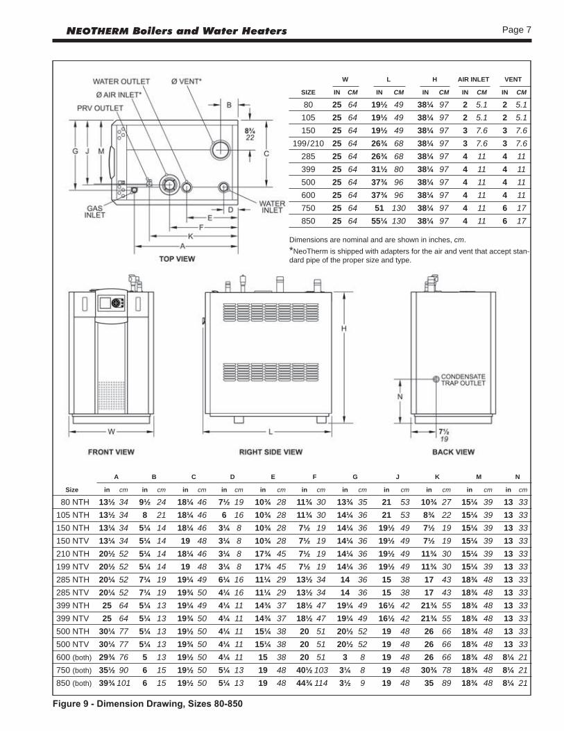
Figure9-DimensionDrawing,Sizes80-850
Dimensions are nominal and are shown in inches, cm.*NeoTherm is shipped with adapters for the air and vent that accept stan-dard pipe of the proper size and type.
A B C D E F G J K M N
Size in cm in cm in cm in cm in cm in cm in cm in cm in cm in cm in cm
80 NTH 13½ 34 9½ 24 18¼ 46 7½ 19 10¾ 28 11¾ 30 13¾ 35 21 53 10¾ 27 15¼ 39 13 33 105 NTH 13½ 34 8 21 18¼ 46 6 16 10¾ 28 11¾ 30 14¼ 36 21 53 8¾ 22 15¼ 39 13 33 150 NTH 13¼ 34 5¼ 14 18¼ 46 3¼ 8 10¾ 28 7½ 19 14¼ 36 19½ 49 7½ 19 15¼ 39 13 33 150 NTV 13¼ 34 5¼ 14 19 48 3¼ 8 10¾ 28 7½ 19 14¼ 36 19½ 49 7½ 19 15¼ 39 13 33 210 NTH 20½ 52 5¼ 14 18¼ 46 3¼ 8 17¾ 45 7½ 19 14¼ 36 19½ 49 11¾ 30 15¼ 39 13 33 199 NTV 20½ 52 5¼ 14 19 48 3¼ 8 17¾ 45 7½ 19 14¼ 36 19½ 49 11¾ 30 15¼ 39 13 33 285 NTH 20¼ 52 7¼ 19 19¼ 49 6¼ 16 11¼ 29 13½ 34 14 36 15 38 17 43 18¾ 48 13 33 285 NTV 20¼ 52 7¼ 19 19¾ 50 4¼ 16 11¼ 29 13½ 34 14 36 15 38 17 43 18¾ 48 13 33 399 NTH 25 64 5¼ 13 19¼ 49 4¼ 11 14¾ 37 18½ 47 19¼ 49 16½ 42 21¾ 55 18¾ 48 13 33 399 NTV 25 64 5¼ 13 19¾ 50 4¼ 11 14¾ 37 18½ 47 19¼ 49 16½ 42 21¾ 55 18¾ 48 13 33 500 NTH 30¼ 77 5¼ 13 19½ 50 4¼ 11 15¼ 38 20 51 20½ 52 19 48 26 66 18¾ 48 13 33 500 NTV 30¼ 77 5¼ 13 19¾ 50 4¼ 11 15¼ 38 20 51 20½ 52 19 48 26 66 18¾ 48 13 33 600 (both) 29¾ 76 5 13 19½ 50 4¼ 11 15 38 20 51 3 8 19 48 26 66 18¾ 48 8¼ 21 750 (both) 35½ 90 6 15 19½ 50 5¼ 13 19 48 40½ 103 3¼ 8 19 48 30¾ 78 18¾ 48 8¼ 21 850 (both) 39¾ 101 6 15 19½ 50 5¼ 13 19 48 44¾ 114 3½ 9 19 48 35 89 18¾ 48 8¼ 21
W L H AIR INLET VENT
SIZE IN CM IN CM IN CM IN CM IN CM
80 25 64 19½ 49 38¼ 97 2 5.1 2 5.1 105 25 64 19½ 49 38¼ 97 2 5.1 2 5.1 150 25 64 19½ 49 38¼ 97 3 7.6 3 7.6 199/210 25 64 26¾ 68 38¼ 97 3 7.6 3 7.6 285 25 64 26¾ 68 38¼ 97 4 11 4 11 399 25 64 31½ 80 38¼ 97 4 11 4 11 500 25 64 37¾ 96 38¼ 97 4 11 4 11 600 25 64 37¾ 96 38¼ 97 4 11 4 11 750 25 64 51 130 38¼ 97 4 11 6 17 850 25 64 55¼ 130 38¼ 97 4 11 6 17
Page 8 LAARS Heating Systems
Section 2 - LOCATING THE APPLIANCE
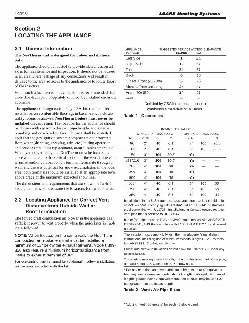
2.1 GeneralInformationThe NeoTherm unit is designed for indoor installations only.The appliance should be located to provide clearances on all sides for maintenance and inspection. It should not be located in an area where leakage of any connections will result in damage to the area adjacent to the appliance or to lower floors of the structure.When such a location is not available, it is recommended that a suitable drain pan, adequately drained, be installed under the appliance. The appliance is design certified by CSA-International for installation on combustible flooring; in basements; in closets, utility rooms or alcoves. NeoTherm Boilers must never be installed on carpeting. The location for the appliance should be chosen with regard to the vent pipe lengths and external plumbing and on a level surface. The unit shall be installed such that the gas ignition system components are protected from water (dripping, spraying, rain, etc.) during operation and service (circulator replacement, control replacement, etc.). When vented vertically, the NeoTherm must be located as close as practical to the vertical section of the vent. If the vent terminal and/or combustion air terminal terminate through a wall, and there is potential for snow accumulation in the local area, both terminals should be installed at an appropriate level above grade or the maximum expected snow line.The dimensions and requirements that are shown in Table 1 should be met when choosing the locations for the appliance.
2.2 LocatingApplianceforCorrectVentDistancefromOutsideWallor RoofTermination
The forced draft combustion air blower in the appliance has sufficient power to vent properly when the guidelines in Table 2 are followed.
NOTE: When located on the same wall, the NeoTherm combustion air intake terminal must be installed a minimum of 12” below the exhaust terminal.Models 399-850 also require a minimum horizontal distance from intake to exhaust terminal of 36”.For concentric vent terminal kit (optional), follow installation instructions included with the kit.
APPLIANCE SUGGESTED SERVICE ACCESS CLEARANCE SURFACE INCHES CM
Left Side 1 2.5 Right Side 12 31 Top 24 61 Back 6 15 Closet, Front (285-500) 6 15 Alcove, Front (285-500) 24 61 Front (600-850) 24 61 Vent – –
Certified by CSA for zero clearance tocombustible materials on all sides.
Table1-Clearances
INTAKE / EXHAUST STANDARD MAX EQUIV. OPTIONAL MAX EQUIV. SIZE VENT FT. M VENT FT. M
80 2” 40 6.1 3” 100 30.5 105 2” 40 6.1 3” 100 30.5 150 3” 100 30.5 n/a — — 199/210 3” 100 30.5 n/a — — 285 4” 100 30 n/a — — 399 4” 100 30 n/a — — 500 4” 100 30 n/a — — 600* 4” 40 6.1 6” 100 30 750 4” 40 6.1 6” 100 30 850 4” 40 6.1 6” 100 30Installations in the U.S. require exhaust vent pipe that is a combination of PVC & CPVC complying with ANSI/ASTM D1785 F441 or stainless steel complying with UL1738. Installations in Canada require exhaust vent pipe that is certified to ULC S636.
Intake (air) pipe must be PVC or CPVC that complies with ANSI/ASTM D1785 F441, ABS that complies with ANSI/ASTM D1527 or galvanized material.
The installer must comply fully with the manufacturer’s installation instructions, including use of minimum exhaust length CPVC, to main-tain ANSI Z21.13 safety certification.
Closet and alcove installations do not allow the use of PVC under any circumstances
To calculate max equivalent length, measure the linear feet of the pipe, and add 5 feet (1.5m) for each 90°* elbow used.
* For any combination of vent and intake lengths up to 40 equivalent feet, any even or uneven combination of length is allowed. For overall lengths greater than 40 equivalent feet, the exhaust may be up to 20 feet greater than the intake length.
Table2-Vent/AirPipeSizes
*Add 2 1/2 feet (.76 meters) for each 45 elbow used.

Page 9NEOTHERM Boilers and Water Heaters
Method 1: Two permanent openings, one commencing within 12” (300mm) of the top and one commencing within 12” (300mm) of the bottom, of the enclosure shall be provided. The openings shall communicate directly, or by ducts, with the outdoors or spaces that freely communicate with the outdoors. When directly communicating with the outdoors, or when communicating to the outdoors through vertical ducts, each opening shall have a minimum free area of 1 square inch per 4000 Btu/hr (550 square mm/kW) of total input rating of all equipment in the enclosure. When communicating to the outdoors through horizontal ducts, each opening shall have a minimum free area of not less than 1 square inch per 2000 Btu/hr (1100 square mm/kW) of total input rating of all equipment in the enclosure.Method 2: One permanent opening, commencing within 12” (300mm) of the top of the enclosure, shall be permitted. The opening shall directly communicate with the outdoors or shall communicate through a vertical or horizontal duct to the outdoors or spaces that directly communicate with the outdoors and shall have a minimum free area of 1 square inch per 3000 Btu/hr (734 square mm/kW) of the total input rating of all equipment located in the enclosure. This opening must not be less than the sum of the areas of all vent connectors in the confined space.
Section 3 - VENTING AND COMBUSTION AIR
3.1 CombustionAirNeoTherm boilers and water heaters must have provisions for combustion and ventilation air in accordance with the applicable requirements for Combustion Air Supply and Ventilation in the National Fuel Gas Code, ANSI Z223 1; or in Canada, the Natural Gas and Propane Installation Code, CSA B149.1. All applicable provisions of local building codes must also be adhered to.A NeoTherm unit can take combustion air from the space in which it is installed, or the combustion air can be ducted directly to the unit. Ventilation air must be provided in either case.
CombustionAirFromRoomIn the United States, the most common requirements specify that the space shall communicate with the outdoors in accordance with method 1 or 2, which follow. Where ducts are used, they shall be of the same cross-sectional area as the free area of the openings to which they connect.
INSTALLATION STANDARDS
MATERIAL UNITED STATES CANADA
ABS ANSI/ASTM D1527 PVC, sch 40 ANSI/ASTM D1785 or D2665 Air pipe material must be chosen CPVC, sch 40 ANSI/ASTM F441 based upon the intended application of the boiler.
Single wall galv. steel 26 gauge
Table4-RequiredCombustionAirPipeMaterial
PRO TECH (FasNSeal) HEAT FAB (Saf-T-Vent) Z FLEX (Z-Vent) SIZE Boiler Flue Intake Air Boiler Intermediate Flue Intake Air Boiler Flue Intake Air Adapter Termination Termination Adapter Adapter Termination Termination Adapter Termination Termination 399-600 F303759 FSBS4 FSAIH04 KB285600 9454BUREZ-1* 9492 9414TERM 2SVSLA04 2SVSTP04 2SVSTEX0490 FSRC4(R.C) 303888 5400CI 2SVSRCX04 750-850 F303759 FSBS6 FSAIH04 303888
Table3b-ApprovedStainlessTerminationsandAdapters
HORIZONTAL INTAKE AND EXHAUST PVC VENT TERMINAL KITS
Size
2” PVC 3” PVC 4” PVC 6” PVC
Sta
ndar
d
Con
cent
ric
CA
0060
00
Flus
h M
ount
C
A01
0100
Sta
ndar
d C
A00
5900
Con
cent
ric
239-
4406
9-01
Flus
h M
ount
C
A01
0101
Sta
ndar
d
Flus
h M
ount
C
A01
0102
Sta
ndar
d80 incl. opt. opt. opt. opt. opt. n/a n/a n/a105 incl. opt. opt. opt. opt. opt.l n/a n/a n/a150 n/a n/a n/a incl. opt. opt. n/a n/a n/a199/210 n/a n/a n/a incl. opt. opt. n/a n/a n/a285 n/a n/a n/a opt. opt. opt. incl. opt. n/a399 n/a n/a n/a n/a n/a n/a incl. opt. n/a500 n/a n/a n/a n/a n/a n/a incl. opt. n/a600 n/a n/a n/a n/a n/a n/a incl. opt. opt.750 n/a n/a n/a n/a n/a n/a incl. n/a opt.850 n/a n/a n/a n/a n/a n/a incl. n/a opt.Concentric vent terminal = 10 ft. pipe length
Table3a-PVCVentTerminalKits

Page 10 LAARS Heating Systems
Other methods of introducing combustion and ventilation air are acceptable, providing they conform to the requirements in the applicable codes listed above.In Canada, consult local building and safety codes or, in absence of such requirements, follow CAN/CSA B149.
DuctedCombustionAirThe combustion air can be taken through the wall, or through the roof. When taken from the wall, it must be taken from out-of-doors by means of the LAARS horizontal wall terminal, shown in Table 3a and 3b. See Table 2 to select the appropriate diameter air pipe. When taken from the roof, a field-supplied rain cap or an elbow arrangement must be used to prevent entry of rain water. (See Figure10.)Use ABS, PVC, CPVC or galvanized pipe for the combustion air intake. (See Table 4.) The pipe should be sized per Table 2. Route the intake to the boiler as directly as possible. Seal all joints. Provide adequate hangers. The unit must not support the weight of the combustion air intake pipe. Maximum linear pipe length allowed is shown in Table 2. Subtract 5 allowable linear ft. (1.5m) for every elbow used.The connection for the intake air pipe is at the top of the unit. (See Figure 9.)In addition to air needed for combustion, air shall also be supplied for ventilation, including air required for comfort and proper working conditions for personnel. Refer to the applicable codes.
3.2 Venting
WARNINGFailure to use polypropylene CPVC or stainless steel venting for the first 20” (285-600) / 30” (80-210) of vent material or for any part of the venting that is installed inside a closet may lead to property damage, personal injury or death. The proper length of this material is supplied with boiler. Boilers in the U.S. may use pipe included with the boiler.
Failure to use the appropriate vent material, installation techniques, glues/sealants could lead to vent failure causing property damage, personal injury or death.
All venting must be installed according to this manual and any other applicable local codes, including but not limited to, ANSI Z223.1/NFPA 54, CSA B149.1, CSAB149.2 and ULC-S636. Failure to follow this manual and applicable codes may lead to property damage, severe injury, or death.
The flue temperature of the NeoTherm changes dramatically with changes in operating water temperature. Therefore, it is necessary to assess the application of the boiler to determine the required certified vent class. If the NeoTherm is installed in an application where the ambient temperature is elevated, and/or installed in a closet/alcove, polypropylene, CPVC or stainless steel material is required. If the system temperatures are unknown at the time of installation, Class IIB or higher venting material is recommended.The NeoTherm is a Category IV appliance and may be installed with PVC and CPVC that complies with ANSI/ASTM D1785 F441, polypropylene that complies with ULC-S636 Class IIb, or a stainless steel venting system that complies with UL 1738 Standard. (See Table 5.)The unit’s vent can terminate through the roof, or through an outside wall.When using PVC/CPVC for vent material, venting must be connected to the CPVC section included with NeoTherm sizes 80-850. The CPVC vent section included with the NeoTherm may be broken by CPVC fittings if necessary, but never reduced in total length. See Table 2 to select the appropriate vent pipe diameter. When using polypropylene, all vent material must be produced by the same manufacturer, and have a ULC-S636 rating.
Figure10-CombustionAirandVentThroughRoof INSTALLATION STANDARDS
MATERIAL UNITED STATES CANADA
Stainless Steel UL 1738 Venting must be ULC-S636 certified for use as PVC, sch 40 ANSI/ASTM D1785 venting material. The venting material class must be CPVC, sch 40 ANSI/ASTM F441 chosen based upon the maximum flue gas temperature Polypropylene ULC-S636 and the intended application of the boiler.
Table5-RequiredExhaustVentMaterial
*
*
*
* *
*
* In Canada, refer to CAN/CSA B199.1
Page 11NEOTHERM Boilers and Water Heaters
All installations should be done following the vent supplier’s recommended installation techniques. If manufacturer’s instructions are not available for the material used, follow the Laars recommendations. The vent pipe must pitch upward, toward the vent terminal, not less than 1/4” per foot, so that condensate will run back to the NeoTherm to drain. Route vent pipe to the heater as directly as possible. Seal all joints and provide adequate hangers as required in the venting system manufacturer’s Installation Instructions. Horizontal portions of the venting system must be supported to prevent sagging and may not have any low sections that could trap condensate. The unit must not support the weight of the vent pipe. Please see Table 2 for proper diameter vs. length allowed.
IMPORTANT NOTE ABOUT COMMON VENTING: A single vent that is shared by multiple NeoTherm units MUST be engineered by a competent venting specialist, and involves the selection of draft inducing equipment, hardware and controls to properly balance flue gas pressures. DonotcommonventNeoThermunitsunlesstheventsystemmeetsthisrequirement.NeoThermunitsareneverpermittedtoshareaventwithCategoryIappliances.
VentingRequirementsUniquetoCanadaNeoTherm boilers and water heaters are Vent Category IV appliances. Per the requirements of CAN/CSA-B149.1, only BH vent systems can be connected to these units and such vent systems, either ULC S636 certified stainless steel or other ULC S636 certified BH vent (eg. plastics) must be installed per the vent manufacturer’s certified installation instructions.As a result, two items listed in the Unpacking section (Figure 8) are not included with NeoTherm units for Canada (underlined):
A exhaust vent terminal (not included)B. air intake terminalC. temperature/pressure gauge kitD. circulator pump/wire harness (units with pump)E. CPVC exhaust pipe section (80-500) (not incl.)F. outdoor/system sensor kitG. flow switch kit (399-850)H. alternate size vent/terminal screensJ. exhaust vent adapter CPVC/ST ST (750-850)
It is the responsibility of the appropriately licensed technician installing this NeoTherm unit to use ULC S636 certified vent material consistent with the requirements as described in the Venting and Combustion Air section.
Class I venting systems are suitable for gas-fired appliances producing flue gas temperature of more than 135°C, but not more than 245°C.
Class II venting systems are suitable for gas-fired appliances producing flue gas temperatures of 135°C or less.
Class II venting systems are further classified into four temperature ratings as follows:
A Up to and including 65°C
B Up to and including 90°C
C Up to and including 110°C, and
D Up to and including 135°C
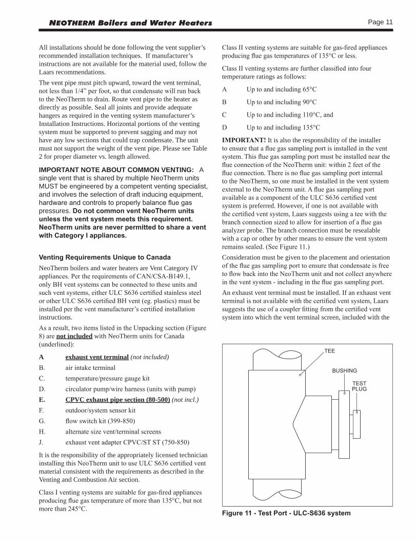
IMPORTANT! It is also the responsibility of the installer to ensure that a flue gas sampling port is installed in the vent system. This flue gas sampling port must be installed near the flue connection of the NeoTherm unit: within 2 feet of the flue connection. There is no flue gas sampling port internal to the NeoTherm, so one must be installed in the vent system external to the NeoTherm unit. A flue gas sampling port available as a component of the ULC S636 certified vent system is preferred. However, if one is not available with the certified vent system, Laars suggests using a tee with the branch connection sized to allow for insertion of a flue gas analyzer probe. The branch connection must be resealable with a cap or other by other means to ensure the vent system remains sealed. (See Figure 11.) Consideration must be given to the placement and orientation of the flue gas sampling port to ensure that condensate is free to flow back into the NeoTherm unit and not collect anywhere in the vent system - including in the flue gas sampling port.An exhaust vent terminal must be installed. If an exhaust vent terminal is not available with the certified vent system, Laars suggests the use of a coupler fitting from the certified vent system into which the vent terminal screen, included with the
Figure11-TestPort-ULC-S636system

Page 12 LAARS Heating Systems
NeoTherm and shown in the Unpacking section, be installed. Be sure to install and terminate both vent and combustion air pipes per the Venting and Combustion Air section of the NeoTherm instructions.
3.3 LocatingVentandCombustionAirTerminals
SideWallVentTerminalThe appropriate Laars side wall vent terminal must be used. The terminal must be located in accordance with ANSI Z223.1/NFPA 54 and applicable local codes. In Canada, the installation must be in accordance with CSA B149.1 or .2 and local applicable codes. Consider the points listed on the following page when installing the terminal.1. Figure 12 shows the requirements for mechanical vent
terminal clearances for the U.S. and Canada.2. Vent terminals for condensing appliances or appliances
with condensing vents are not permitted to terminate above a public walkway, or over an area where condensate or vapor could create a nuisance or hazard.
3. Locate the vent terminal so that vent gases cannot be drawn into air conditioning system inlets.
4. Locate the vent terminal so that vent gases cannot enter the building through doors, windows, gravity inlets or other openings. Whenever possible, avoid locations under windows or near doors.
5. Locate the vent terminal so that it cannot be blocked by snow. The installer may determine that a vent terminal must be higher than the minimum shown in codes, depending upon local conditions.
6. Locate the terminal so the vent exhaust does not settle on building surfaces or other nearby objects. Vent products may damage surfaces or objects.
7. If the boiler or water heater uses ducted combustion air from an intake terminal located on the same wall, see Figures 12-14 for proper spacing and orientation.
If the vent termination is located in an area exposed to high winds, an optional PVC tee (the same diameter as the vent pipe) may be used. The tee’d vent termination offers greater protection from wind related operating issues.
SideWallCombustionAirTerminalThe LAARS side wall combustion air terminal, or concentric terminal must be used when the heater takes air from a side wall. (See Table 3.) Contact Laars for AL29-4C termination fittings. Consider the following when installing the terminal. (See Figures 12-14.)1. Do not locate the air inlet terminal near a source of
corrosive chemical fumes (e.g., cleaning fluid, chlorine compounds, etc.)
2. Locate the terminal so that it will not be subject to
damage by accident or vandalism. It must be at least 7 feet (2.1m) above a public walkway.
3. Locate the combustion air terminal so that it cannot be blocked by snow. The National Fuel Gas Code requires that it be at least 12 inches (30cm) above grade, but the installer may determine it should be higher, depending upon local conditions.
4. If the NeoTherm is side-wall vented to the same wall, locate the vent terminal at least 1 foot (0.3m) above the combustion air terminal.
5. For concentric vent, follow instructions included with vent kit.
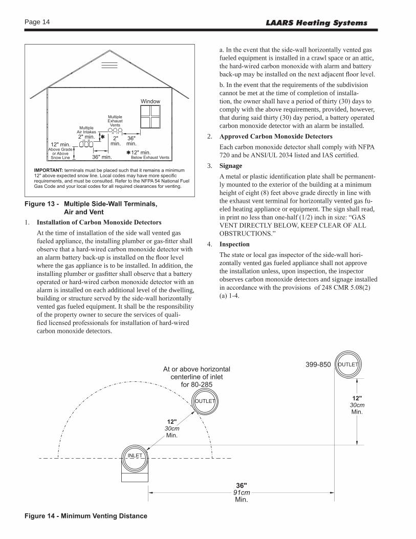
6. Multiple vent kits should be installed such that the horizontal distance between the outlet group and the inlet group is 36” (90cm). (See Figure 13.)
7. The vent outlet for models 80-285 must be no lower than the center of the air inlet, and must be at least 12” (30cm) away from the air inlet. Vent outlets for models 399-850 must be at least 12” above the top of the air inlet, and must be at least 36” (90cm) horizontally from the air inlet. (See Figure 14.)
VerticalVentTerminalWhen the unit is vented through the roof, the vent must extend at least 3 feet (0.9m) above the point at which it penetrates the roof. It must extend at least 2 feet (0.6m) higher than any portion of a building within a horizontal distance of 10 feet (3.0m), and high enough above the roof line to prevent blockage from snow. The vent terminal included with the NeoTherm can be used in both vertical and horizontal applications. When the combustion air is taken from the roof, the combustion air must terminate at least 12” (30cm) below the vent terminal. (See Figure 10.)
VerticalCombustionAirTerminalWhen combustion air is taken from the roof, a field-supplied rain cap or an elbow arrangement must be used to prevent entry of rain water. (See Figure 10.) The opening on the end of the terminal must be at least 12” (30cm) above the point at which it penetrates the roof, and high enough above the roof line to prevent blockage from snow. When the vent terminates on the roof, the combustion air must terminate at least 12” (30cm) below the vent terminal.
InstallationsintheCommonwealthofMassachusettsIn Massachusetts the following items are required if the side-wall exhaust vent termination is less than seven (7) feet above finished grade in the area of the venting, including but not limited to decks and porches. From Massachusetts Rules and regulations 248 CMR 5.08 (begininning on 2nd page following):
Page 13NEOTHERM Boilers and Water Heaters
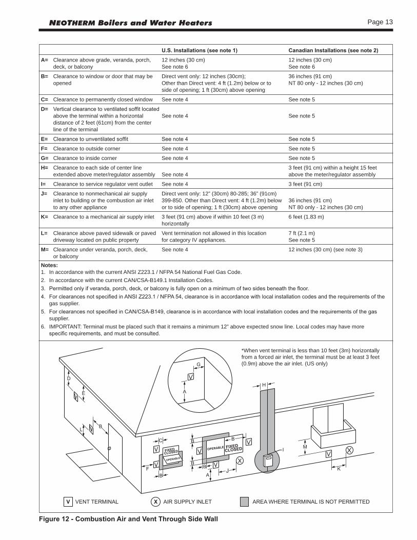
*When vent terminal is less than 10 feet (3m) horizontally from a forced air inlet, the terminal must be at least 3 feet (0.9m) above the air inlet. (US only)
Figure12-CombustionAirandVentThroughSideWall
U.S.Installations(seenote1) CanadianInstallations(seenote2)
A= Clearance above grade, veranda, porch, 12 inches (30 cm) 12 inches (30 cm) deck, or balcony See note 6 See note 6
B= Clearance to window or door that may be Direct vent only: 12 inches (30cm); 36 inches (91 cm) opened Other than Direct vent: 4 ft (1.2m) below or to NT 80 only - 12 inches (30 cm) side of opening; 1 ft (30cm) above opening
C= Clearance to permanently closed window See note 4 See note 5
D= Vertical clearance to ventilated soffit located above the terminal within a horizontal See note 4 See note 5 distance of 2 feet (61cm) from the center line of the terminal
E= Clearance to unventilated soffit See note 4 See note 5
F= Clearance to outside corner See note 4 See note 5
G= Clearance to inside corner See note 4 See note 5
H= Clearance to each side of center line 3 feet (91 cm) within a height 15 feet extended above meter/regulator assembly See note 4 above the meter/regulator assembly
I= Clearance to service regulator vent outlet See note 4 3 feet (91 cm)
J= Clearance to nonmechanical air supply Direct vent only: 12” (30cm) 80-285; 36” (91cm) inlet to building or the combustion air inlet 399-850. Other than Direct vent: 4 ft (1.2m) below 36 inches (91 cm) to any other appliance or to side of opening; 1 ft (30cm) above opening NT 80 only - 12 inches (30 cm)
K= Clearance to a mechanical air supply inlet 3 feet (91 cm) above if within 10 feet (3 m) 6 feet (1.83 m) horizontally
L= Clearance above paved sidewalk or paved Vent termination not allowed in this location 7 ft (2.1 m) driveway located on public property for category IV appliances. See note 5
M= Clearance under veranda, porch, deck, See note 4 12 inches (30 cm) (see note 3) or balconyNotes:1. In accordance with the current ANSI Z223.1 / NFPA 54 National Fuel Gas Code.2. In accordance with the current CAN/CSA-B149.1 Installation Codes.3. Permitted only if veranda, porch, deck, or balcony is fully open on a minimum of two sides beneath the floor.4. For clearances not specified in ANSI Z223.1 / NFPA 54, clearance is in accordance with local installation codes and the requirements of the gas supplier.5. For clearances not specified in CAN/CSA-B149, clearance is in accordance with local installation codes and the requirements of the gas supplier.6. IMPORTANT: Terminal must be placed such that it remains a minimum 12” above expected snow line. Local codes may have more specific requirements, and must be consulted.
Page 14 LAARS Heating Systems
1. Installation of Carbon Monoxide Detectors At the time of installation of the side wall vented gas
fueled appliance, the installing plumber or gas-fitter shall observe that a hard-wired carbon monoxide detector with an alarm battery back-up is installed on the floor level where the gas appliance is to be installed. In addition, the installing plumber or gasfitter shall observe that a battery operated or hard-wired carbon monoxide detector with an alarm is installed on each additional level of the dwelling, building or structure served by the side-wall horizontally vented gas fueled equipment. It shall be the responsibility of the property owner to secure the services of quali-fied licensed professionals for installation of hard-wired carbon monoxide detectors.
a. In the event that the side-wall horizontally vented gas fueled equipment is installed in a crawl space or an attic, the hard-wired carbon monoxide with alarm and battery back-up may be installed on the next adjacent floor level.
b. In the event that the requirements of the subdivision cannot be met at the time of completion of installa-tion, the owner shall have a period of thirty (30) days to comply with the above requirements, provided, however, that during said thirty (30) day period, a battery operated carbon monoxide detector with an alarm be installed.
2. Approved Carbon Monoxide Detectors Each carbon monoxide detector shall comply with NFPA
720 and be ANSI/UL 2034 listed and IAS certified.3. Signage A metal or plastic identification plate shall be permanent-
ly mounted to the exterior of the building at a minimum height of eight (8) feet above grade directly in line with the exhaust vent terminal for horizontally vented gas fu-eled heating appliance or equipment. The sign shall read, in print no less than one-half (1/2) inch in size: “GAS VENT DIRECTLY BELOW, KEEP CLEAR OF ALL OBSTRUCTIONS.”
4. Inspection The state or local gas inspector of the side-wall hori-
zontally vented gas fueled appliance shall not approve the installation unless, upon inspection, the inspector observes carbon monoxide detectors and signage installed in accordance with the provisions of 248 CMR 5.08(2)(a) 1-4.
Figure14-MinimumVentingDistance
Figure13- MultipleSide-WallTerminals, AirandVent
Page 15NEOTHERM Boilers and Water Heaters
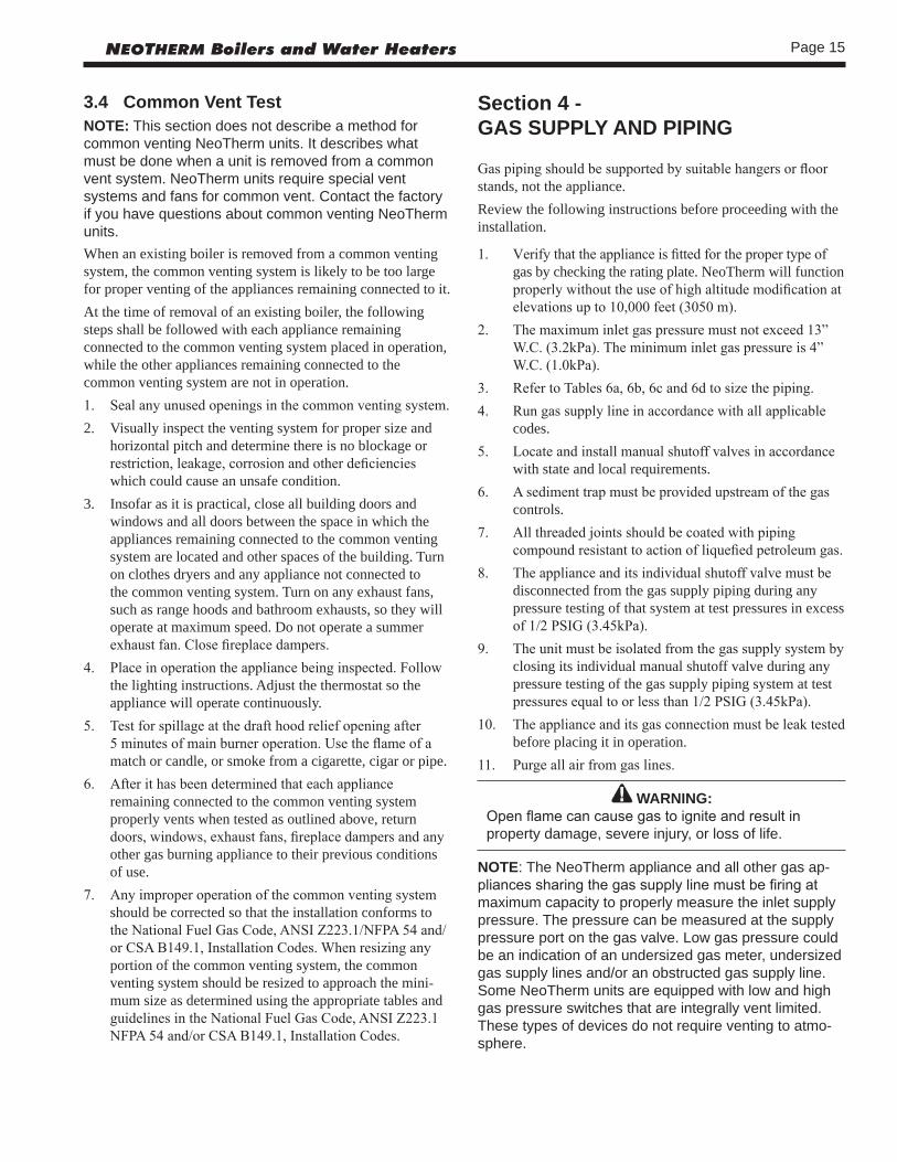
Section 4 - GAS SUPPLY AND PIPING
Gas piping should be supported by suitable hangers or floor stands, not the appliance.Review the following instructions before proceeding with the installation.
1. Verify that the appliance is fitted for the proper type of gas by checking the rating plate. NeoTherm will function properly without the use of high altitude modification at elevations up to 10,000 feet (3050 m).
2. The maximum inlet gas pressure must not exceed 13” W.C. (3.2kPa). The minimum inlet gas pressure is 4” W.C. (1.0kPa).
3. Refer to Tables 6a, 6b, 6c and 6d to size the piping.4. Run gas supply line in accordance with all applicable
codes. 5. Locate and install manual shutoff valves in accordance
with state and local requirements.6. A sediment trap must be provided upstream of the gas
controls.7. All threaded joints should be coated with piping
compound resistant to action of liquefied petroleum gas.8. The appliance and its individual shutoff valve must be
disconnected from the gas supply piping during any pressure testing of that system at test pressures in excess of 1/2 PSIG (3.45kPa).
9. The unit must be isolated from the gas supply system by closing its individual manual shutoff valve during any pressure testing of the gas supply piping system at test pressures equal to or less than 1/2 PSIG (3.45kPa).
10. The appliance and its gas connection must be leak tested before placing it in operation.
11. Purge all air from gas lines.
WARNING:Open flame can cause gas to ignite and result in property damage, severe injury, or loss of life.
NOTE: The NeoTherm appliance and all other gas ap-pliances sharing the gas supply line must be firing at maximum capacity to properly measure the inlet supply pressure. The pressure can be measured at the supply pressure port on the gas valve. Low gas pressure could be an indication of an undersized gas meter, undersized gas supply lines and/or an obstructed gas supply line. Some NeoTherm units are equipped with low and high gas pressure switches that are integrally vent limited. These types of devices do not require venting to atmo-sphere.
3.4 Common Vent TestNOTE: This section does not describe a method for common venting NeoTherm units. It describes what must be done when a unit is removed from a common vent system. NeoTherm units require special vent systems and fans for common vent. Contact the factory if you have questions about common venting NeoTherm units.When an existing boiler is removed from a common venting system, the common venting system is likely to be too large for proper venting of the appliances remaining connected to it.At the time of removal of an existing boiler, the following steps shall be followed with each appliance remaining connected to the common venting system placed in operation, while the other appliances remaining connected to the common venting system are not in operation.1. Seal any unused openings in the common venting system.2. Visually inspect the venting system for proper size and
horizontal pitch and determine there is no blockage or restriction, leakage, corrosion and other deficiencies which could cause an unsafe condition.
3. Insofar as it is practical, close all building doors and windows and all doors between the space in which the appliances remaining connected to the common venting system are located and other spaces of the building. Turn on clothes dryers and any appliance not connected to the common venting system. Turn on any exhaust fans, such as range hoods and bathroom exhausts, so they will operate at maximum speed. Do not operate a summer exhaust fan. Close fireplace dampers.
4. Place in operation the appliance being inspected. Follow the lighting instructions. Adjust the thermostat so the appliance will operate continuously.
5. Test for spillage at the draft hood relief opening after 5 minutes of main burner operation. Use the flame of a match or candle, or smoke from a cigarette, cigar or pipe.
6. After it has been determined that each appliance remaining connected to the common venting system properly vents when tested as outlined above, return doors, windows, exhaust fans, fireplace dampers and any other gas burning appliance to their previous conditions of use.
7. Any improper operation of the common venting system should be corrected so that the installation conforms to the National Fuel Gas Code, ANSI Z223.1/NFPA 54 and/or CSA B149.1, Installation Codes. When resizing any portion of the common venting system, the common venting system should be resized to approach the mini-mum size as determined using the appropriate tables and guidelines in the National Fuel Gas Code, ANSI Z223.1 NFPA 54 and/or CSA B149.1, Installation Codes.

Page 16 LAARS Heating Systems
SCHED 40 METAL PIPE CAPACITY FOR 1.50 SPECIFIC GRAVITYUNDILUTED PROPANE
NOMINAL PIPE SIZE @ 11” W.C. INLET AND 0.5” W.C. PRESSURE DROP
SIZE 1/2” 3/4” 1” 1-1/4” 1-1/2” 2” LENGTH MAXIMUM CAPACITY IN THOUSANDS OF BTU PER HOUR
20 200 418 787 1616 2422 4664 40 137 287 541 1111 1664 3205 60 110 231 434 892 1337 2574 80 94 197 372 763 1144 2203 100 84 175 330 677 1014 1952
NOTES:1. Follow all local and national LP gas codes for line sizing and equipment requirements.2. Verify that inlet gas pressure remains between 4 and 13 inches of water column before and during operation. Source: ANSI Z223.1-80 National Fuel Gas Code.
Table6d
EQUIVALENT LENGTHS OF STRAIGHT PIPE FOR TYPICAL SCH 40 FITTINGS
NOMINAL PIPE SIZE
FITTING 1/2” 3/4” 1” 1-1/4” 1-1/2” 2”LINEAR FEET
90° ELBOW 3.6 4.4 5.2 6.6 7.4 8.5 TEE 4.2 5.3 6.6 8.7 9.9 12
Table6b
SCH 40 METAL PIPE CAPACITY FOR 0.60 SPECIFIC GRAVITY NATURAL GASNOMINAL PIPE SIZE @ 0.30” W.C. PRESSURE DROP
LENGTH 1/2” 3/4” 1” 1-1/4” 1-1/2” 2” FT CUBIC FEET OF GAS PER HOUR
20 92 190 350 730 1100 2100 40 130 245 500 760 1450 60 105 195 400 610 1150 80 90 170 350 530 990 100 150 305 460 870
Table6c
NEOTHERM NATURAL GAS REQUIRED CU FT SIZE / HR.
80 80 105 105 150 150 199/210 199/210 285 285 399 399 500 500 600 600 750 750 850 850
Table6a
TO SIZE PIPING:Measure linear distance from meter outlet to last boiler. Add total input of all boilers and divide by 1000 to obtain cu ft / hr required. Add total equivalent length of fittings used according to Table 6B. Align total length (pipe and fittings) on left side column of Table 6C with highest cubic feet of gas required.
Notes: Consult and confirm with Applicable Fuel Gas Code before beginning work. Verify gas inlet pressure is between 4 and 13 in W.C. before starting boiler.
Section 5 -PUMP REQUIREMENTS
5.1 NeoThermBoilerFlowandHeadRequirements
NORMAL WATER*
Flow H/L Temp Flow H/L TempSize gpm feet Rise°F lpm m Rise °C150 19 49 15 72 14.9 8199 25 28 15 95 8.5 8285 36 33 15 98 10.1 8399 50 35 15 189 10.7 8500 63 28 15 239 8.5 8600** 60 24 19 227 7.3 11750** 68 35 21 257 10.7 12850** 68 26 24 257 7.9 13
* Maximum water hardness of 10 grains per gallon allowed.** See section 6B.7 on page 27 for pump information.Table8-WaterHeaterFlowData
5.2 NeoThermWaterHeaterFlowandHeadRequirements
TEMPERATURE RISE IN °F
20°F 25°F 30°F 35°F 40°F FLOW H/L FLOW H/L FLOW H/L FLOW H/L FLOW H/LSIZE GPM FT GPM FT GPM FT GPM FT GPM FT
80 7.6 14.9 6.1 10.1 5.1 7.1 4.3 5.8 3.8 4.6105 10 23.1 8 17 6.7 12.4 5.7 9.6 5 7.6150 14.3 28.5 11.4 19 9.5 13.6 8.1 11.2 7.1 8.8210 20 24.1 16 16.7 13.4 11.6 11.3 9 9.9 6.9285 27 25.5 22 17.5 18 14 15 10.5 13 8399 39 28 31 20 25 14.5 22 11 19 9500 48 24 38 16 32 12 27 9 24 8600 58 44 46 31 38 22 33 18 29 15750 72 37 58 23 48 17 41 13 36 10850 81 33 65 22 54 15 46 10 41 8
TEMPERATURE RISE IN °C
11°C 14°C 17°C 19°C 22°C FLOW H/L FLOW H/L FLOW H/L FLOW H/L FLOW H/LSIZE lpm m lpm m lpm m lpm m lpm m
80 29 4.5 23 3.1 19 2.2 16 1.8 14 1.4105 38 7.0 30 5.2 25 3.8 22 2.9 19 2.3150 54 8.7 43 5.8 36 4.1 31 3.4 27 2.7210 76 7.3 61 5.1 51 3.5 43 2.7 37 2.1285 102 7.8 83 5.3 68 4.3 57 3.2 49 2.4399 148 8.5 117 6.1 95 4.4 83 3.4 72 2.7500 182 7.3 144 4.9 121 3.7 102 2.7 91 2.4600 220 13.4 174 9.4 144 6.7 125 5.5 110 4.6750 273 11.3 220 7.0 182 5.2 155 4.0 136 3.0850 307 10.1 246 6.7 204 4.6 174 3.0 155 2.4
Table7-WaterFlowRequirements

Page 17NEOTHERM Boilers and Water Heaters
NeoTherm’s efficiency is higher with lower return water temperatures. Therefore, to get the most of low return temperature with multiple boilers, pipe as shown in Figures 17-19.NeoTherm NTV models 150-500 can be ordered with or without a pump included.NeoTherm NTH models 80-500 can also be ordered with or without a pump included.NeoTherm with a pump MUST be piped in a primary-secondary fashion (using either piping or a hydraulic separator) such that the pump that is mounted on the boiler ONLY serves the boiler.When the pump is supplied by Laars, the NeoTherm boiler must be located within 15 feet (4.6m) of the supply and return header (or the hydraulic separator). Pumps supplied by Laars are sized for a maximum of 30 feet (9.1m) of connection size piping and the headloss of the boiler only. (See Table 7.)If longer pipe lengths are required, the pump should be sized for the boiler per Table 7 and for the piping it will serve, and should be supplied to job separately. Even with pumps supplied by others, Laars strongly recommends primary-secondary piping.
6A.2NTHColdWaterMake-Up1. Connect the cold water supply to the inlet connection of
an automatic fill valve.2. Install a suitable back flow preventer between the
automatic fill valve and the cold water supply.3. Install shut off valves where required.
The boiler piping system of a hot water heating boiler connected to heating coils located in air handling appliances where they may be exposed to refrigerated air circulation must be equipped with flow control valves or other automatic means to prevent gravity circulation of the boiler water during the cooling cycle.A boiler installed above radiation level, or as required by the authority having jurisdiction, must be provided with a low water cutoff device either as a part of the boiler or at the time of boiler installation.
NTH PIPESIZE, NTV PIPESIZE, SIZE INCHES SIZE INCHES
80 1 – n/a 105 1 – n/a 150 1 150 1¼ 210 1¼ 199 1¼ 285 1¼ 285 2 399 1¼ 399 2 500 1½ 500 2 600 1½ 600 2 750 2 750 2 850 2 850 2
Table9-WaterConnectionPipeSizes
Section 6A -WATER CONNECTIONS -NTH BOILERSection 6 is divided into two parts. Section 6A covers NTH units designed for hydronic heating. Section 6B covers NTV models, which are designed exclusively for “volume water” domestic hot water applications. Refer to the proper section for instructions on installing and piping your product. Refer to Table 9 for the connection pipe sizes required.
6A.1 NTHSystemPiping- HotSupplyConnections
NOTE: This appliance must be installed in a closed pressure system with a minimum of 12 psi (82.7kPa) static pressure at the boiler.Hot water piping should be supported by suitable hangers or floor stands. Do not support piping with this appliance. Due to expansion and contraction of copper pipe, consideration should be given to the type of hangers used. Rigid hangers may transmit noise through the system resulting from the piping sliding in the hangers. It is recommended that padding be used when rigid hangers are installed. Maintain 1” (2.5cm) clearance to combustibles for hot water pipes.Pipe the discharge of the relief valve (full size) to a drain or in a manner to prevent injury in the event of pressure relief. Install an air purger, an air vent, a diaphragm-type expansion tank, and a hydronic flow check in the system supply loop. Minimum fill pressure must be 12psig (82.7kPa). Install shutoff valves where required by code.

Page 18 LAARS Heating Systems
6A.3CondensateDrainA condensate drain trap is built into the NeoTherm unit.Connect a 3/4” PVC pipe between the drain connection and a floor drain (or a condensate pump if a floor drain is not accessible).The condensate drain must be installed so as to prevent accumulation of condensate. When a condensate pump is not used, the tubing must continuously slope downward toward the drain with no spiraling.Consult local codes for the proper disposal method for the condensate.
CautionCondensate is mildly acidic (pH = 5), and may harm some floor drains and/or pipes, particularly those that are metal. Ensure that the drain, drainpipe, and anything that will come in contact with the condensate can withstand the acidity, or neutralize the condensate before disposal. Damagecausedbyfailuretoinstallaneutralizerkitortoadequatelytreatcondensatewillnotbethemanufacturer’sresponsibility.
6A.4 Freeze Protection
WARNINGGlycol must not be used in domestic hot water applications. Refer to Section 6B.4 for instructions on NTV, domestic hot water freeze protection.
NeoTherm units are certified for indoor use only, and are not design-certified for placement outdoors.Proper precautions for freeze protection are recommended for boiler installations in areas where the danger of freezing exists.Power outage, interruption of gas supply, failure of system components, activation of safety devices, etc., may prevent a boiler from firing. Any time a boiler is subjected to freezing conditions, and the boiler is not able to fire, and/or the water is not able to circulate, there is a risk of freezing in the boiler or in the pipes in the system. When water freezes, it expands which may result in bursting of pipes, or damage to the boiler, which could result in leaking or flooding conditions.Do not use automotive antifreeze. To help prevent freezing, Laars recommends the use of inhibited glycol concentrations between 20% and 35% glycol. Typically, this concentration will serve as burst protection for temperatures down to approximately -5°F (-20°C). If temperatures are expected to be lower than -5°F (-20°C), glycol concentrations up to 50% can be used. When concentrations greater than 35% are used, water flow rates must be increased to maintain a 20°F to 25°F
temperature rise through the boiler. NOTE: Laars supplied pumps are not all capable of maintaining the reduced temperature rise required with glycol concentrations greater than 35%. If glycol concentrations required are greater than 35% a field supplied pump should be used.
CautionDifferent glycol products may provide varying degrees of protection. Glycol products must be maintained properly in a heating system, or they may become ineffective. Consult the glycol specifications, or the glycol manufacturer, for information about specific products, maintenance of solutions, and set up according to your particular conditions.
6A.5NTHSuggestedPipingSchematicsFigures 15 through 21 show suggested piping configurations for NTH boilers. These diagrams are only meant as a guide. All components or piping required by local code must be installed.
6A.6RecognizedChemicals The following manufacturers offer glycols, inhibitors, and anti foamants that are suitable for use in the NeoTherm. Please refer to the manufacturers instructions for proper selection and application.
1. Sentinel Performance Solutions Group2. Hercules Chemical Company3. Dow Chemical Company

Page 19NEOTHERM Boilers and Water Heaters
Figure15-HydronicPiping—SingleBoiler,ZoningwithCirculators
Page 20 LAARS Heating Systems
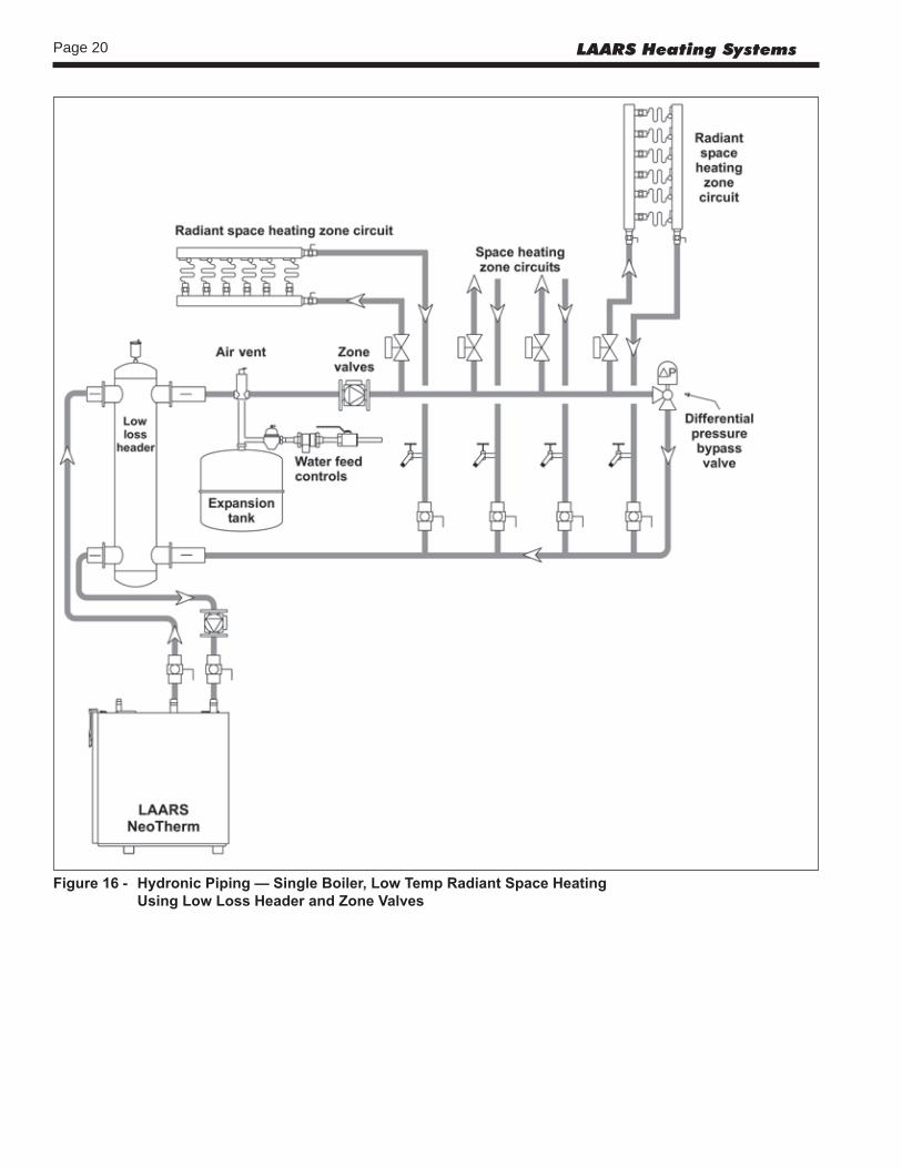
Figure16- HydronicPiping—SingleBoiler,LowTempRadiantSpaceHeating UsingLowLossHeaderandZoneValves

Page 21NEOTHERM Boilers and Water Heaters
Figure17-HydronicPiping—MultipleBoilers,ZoningwithCirculators
Page 22 LAARS Heating Systems
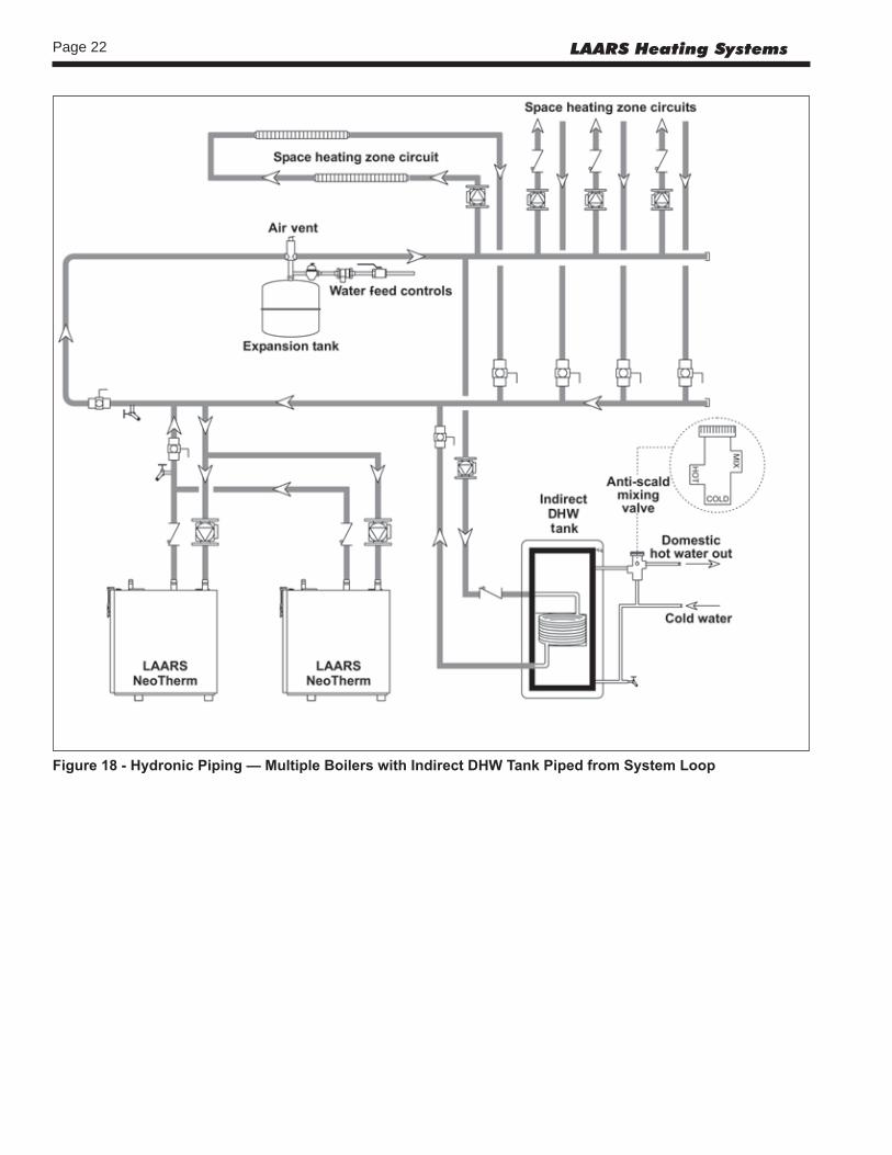
Figure18-HydronicPiping—MultipleBoilerswithIndirectDHWTankPipedfromSystemLoop

Page 23NEOTHERM Boilers and Water Heaters
Figure19-HydronicPiping—MultipleBoilers,ReverseReturn,Multi-TempZones,ZoningwithCirculators

Page 24 LAARS Heating Systems
Figure20-HydronicPiping—HeatingZoneswithIndirectDHWTankPipedwithZonePumpsThe indirect DHW tank is piped directly off of the boiler. The boiler pump must shut down during DHW operation.

Page 25NEOTHERM Boilers and Water Heaters
Figure21-HydronicPiping,MultipleBoilerswithIndirectDHWOffofOneBoilerThe boiler pump must shut down during DHW operation.

Page 26 LAARS Heating Systems
6B.2PipingRequirementsWater piping should be supported by suitable hangers and floor stands. Do not support piping with the appliance. Due to expansion and contraction of copper pipe, consideration should be given to the type of hangers and supports used. Rigid hangers may transmit noise through the system resulting from piping sliding in the hangers. It is recommended that padding be used when rigid hangers are installed. Maintain 1” (2.5cm) clearance to combustibles for hot water pipes.Pipe the discharge of the relief valve (full size) to the drain or in a manner to prevent injury in the event of pressure relief. Install a diaphragm-type expansion tank, flow check, and shutoff valves where needed or as required by code.NeoTherm 150-500 can be ordered with pumps. Whether the factory pumps or other pumps are installed the piping should be installed such that the pump supplies flow to the heater it is attached to only. The factory pumps are sized for 30 feet and 6 elbows of total pipe length, so the heater should be placed within 15 feet of the tank. If longer runs are required, a properly-sized field-supplied pump should be used.
Section 6B -WATER CONNECTIONS -NTV WATER HEATERSection 6 is divided into two parts. Section 6A covers NTH units designed for hydronic heating. Section 6B covers NTV models, which are designed exclusively for “volume water” domestic hot water applications. Refer to the proper section for instructions on installing and piping your product. Refer to Table 9 for the connection pipe sizes required.
6B.1NTVWaterQualityNTV water heaters must be installed in water conditions of 10gpg hardness or less with a pH range of 8.2 to 9.5. Operating the NTV in water with higher hardness levels will cause heat exchanger fouling, erosion, or corrosion leading to premature component failure, reduced efficiency, heat exchanger failure or system failure. Failure of this type will not be warranted. If the water in use exceeds the conditions recommended, a water softener or other device should be installed to improve water quality.
Figure22-DHWPiping,OneHeater,OneVerticalTank
NOTES:1. Optional CWMU & Recirc. line location.2. Locate NTV DHW sensor or remote aquastat well in lower 1/3 of tank.3. Back flow preventer may be required - check local codes.4. Thermal expansion tank may be required - check local codes.5. Factory mounted pumps are sized for a max pipe length of 30’ total, 6-90° elbows, full pipe size.6. Caution:Pumpsizingmustbebasedonwaterhardnessatjobsite.
WARNING: This drawing shows suggested piping configuration and valving. Check with local codes and ordinances for additional requirements.

Page 27NEOTHERM Boilers and Water Heaters
6B.3ColdWaterMake-UpThe cold water make-up may be connected to the tank or to the inlet of the boiler as shown in Figures 22-25. Install back flow preventers and shut offs where needed or required by code. Pipe sizes may have to be increased to accomodate cold water make-up flow.
6A.4CondensateDrainA condensate drain trap is built into the NeoTherm unit.Connect a 3/4” PVC pipe between the drain connection and a floor drain (or a condensate pump if a floor drain is not accessible).The condensate drain must be installed so as to prevent accumulation of condensate. When a condensate pump is not used, the tubing must continuously slope downward toward the drain with no spiraling.Consult local codes for the proper disposal method for the condensate.
CautionCondensate is mildly acidic (pH = 5), and may harm some floor drains and/or pipes, particularly those that are metal. Ensure that the drain, drainpipe, and anything that will come in contact with the condensate can withstand the acidity, or neutralize the condensate before disposal. Damagecausedbyfailuretoinstallaneutralizerkitortoadequatelytreatcondensatewillnotbethemanufacturer’sresponsibility.
6B.5 Freeze ProtectionNeoTherm heaters are not certified for outdoor installation, so the chance of freezing is minimized. In an event such as power outage, component failure or other issue when freezing is likely, the heater and system must be drained to avoid the risk of damage due to freezing. Glycol must not be used in volume water heating applications.
6B.6NTVSuggestedPipingSchematicsFigures 23-25 show suggested piping configurations for NTV boilers. These diagrams are only meant as guides. All components or piping required by local code must be installed.
6B.7 NTV Suggested PumpsPossible pumps for NTV sizes 600-850 are Grundfos model TP 40-160/2B, or for size 600 (only) is Armstrong model E22B. See Table 8 for heater water flow and head requirements.Note - The head loss for the piping, fittings, and accessories must be calculated and added to the heater head loss to get the total required pump head. An undersized pump will result in insufficient flow. The can result in scale buildup and failure of the heat exchanger.

Page 28 LAARS Heating Systems
Figure23-DHWPiping,OneHeater,TwoVerticalTanks
NOTES:1. Optional CWMU & Recirc. line location.2. Locate NTV DHW sensor or remote aquastat well in lower 1/3 of tank.3. Back flow preventer may be required - check local codes.4. Thermal expansion tank may be required - check local codes.5. Factory mounted pumps are sized for a max pipe length of 30’ total, 6-90° elbows, full pipe size.6. Caution:Pumpsizingmustbebasedonwater hardnessatjobsite.
WARNING: This drawing shows suggested piping configuration and valving. Check with local codes and ordinances for additional requirements.

Page 29NEOTHERM Boilers and Water Heaters
Figure24-DHWPiping,TwoHeaters,OneVerticalTank
Figure25-DHWPiping,TwoHeaters,TwoVerticalTanks
NOTES:1. Optional CWMU & Recirc. line location.2. Locate NTV DHW sensor or remote aquastat well in lower 1/3 of tank.3. Back flow preventer may be required - check local codes.4. Thermal expansion tank may be required - check local codes.5. Factory mounted pumps are sized for a max pipe length of 30’ total, 6-90° elbows, full pipe size.6. Caution:Pumpsizingmustbebasedon waterhardnessatjobsite.
WARNING: This drawing shows suggested piping configuration and valving. Check with local codes and ordinances for additional requirements.
NOTES:1. Optional CWMU & Recirc. line location.2. Locate NTV DHW sensor or remote aquastat well in lower 1/3 of tank.3. Back flow preventer may be required - check local codes.4. Thermal expansion tank may be required - check local codes.5. Factory mounted pumps are sized for a max pipe length of 30’ total, 6-90° elbows, full pipe size.6. Caution:Pumpsizingmust bebasedonwater hardnessatjobsite.
WARNING: This drawing shows suggested piping configuration and valving. Check with local codes and ordinances for additional requirements.

Page 30 LAARS Heating Systems
Section 7 -THE USER INTERFACE
7.1 AbouttheUserInterfaceThe User Interface of the NeoTherm used on this unit has two main parts:• the ‘Display’ area and • the ‘Buttons’ The User Interface displays operating and setup information sent from the NeoTherms electronic burner controller and allows the user to set all parameters of the electronic burner controller.
Table10-ButtonFunctionsonUserInterface
Fig.26-TheUserInterface(UI)
Display area This area displays several different kinds of information, including current operating information, setup parameters, and messages from the SOLA controller.
Up/ Down Arrow buttons Use these to go to the choice you want to select in the display area, then press the round OK button.
Left/ Right Arrow buttons Use these to go to the choice you want to select in the display area, then press the round OK button.
Back button Use this to go back to the previous display.Info/ Install button Press this button at any time to go to the sub-menus that allow you to set up
and monitor the controller. Home button Press this button at any time to go back to the Home display. (See the section
on “Home Display.”)Round OK button Use the round OK button to confirm a value or action.
Note – Sometimes the system will present the Keyboard display screen, which also includes a separate “OK” area. This is not the same as the round OK button – the two have different functions.)
InstallOperatingManual Doc#1218G-NH.pdf
Doc#1252-NH.pdf (thisdocument)
The Neotherm ‘User Interface’ was updated for the 2013 model year to the User Interface shown in this manual. For older NeoTherms, you will need to download the 1218G-NH.pdf from the ‘Discontinued Documents’ on Laars.com.
Display area currently showing the Home Display
Up/DownArrowbuttons
Left/RightArrowbuttons
Back button
Info/Installbutton
Home button
Round OK button

Page 31NEOTHERM Boilers and Water Heaters
7.2 NavigatingtheUserInterfaceNavigating into the Display area menus is as easy as it looks. The Info/Install button will be the primary button that you will use to start, and the OK button is what you press to select and approve the parameters that you have set on the Display. The arrow keys are for moving up and down, left and right within the menus. The Back button gets you back to the previous screen. And the Home button gets you back to the Home Display.SeeTable10formoredetails.
7.3 TheHomeDisplayWhen the boiler is operating normally, the controller will display the Home display. See Fig. 27.
Fig.27-HomeDisplay
The Home Display has three sections:• The upper section (customizable) displays the most
important operating information for the unit. In the example shown here, the display is showing the system setpoint, the operating temperature, the outlet and inlet temperatures for the water entering and leaving the boiler, and the outdoor temperature.
• The central section shows some additional operating and setup information. In this case, this area lists the boiler name, boiler state, current demand, and the current password level (the “access status”).
• The lower section shows any current lockouts, holds, or alerts.
7.4 CustomizingyourHomeDisplayTo customize the upper section of your Home Display
• Press “I” Info/Install button• Scroll to highlight “Display Setup”, press OK• Highlight the line you would like to change,(example
”Line 2 Operating Temp”), press OK• Scroll to highlight the parameter that you do want
displayed and then press OK. The new parameter is now displayed on the Home Display.
Repeat this step for the other parameters, if desired.
7.5 Entering/ChangingControlSettingsInfo/InstallDisplayThe Info/Install Display is where you will start every time. All of your Controls, Diagnostics, Setups, and more, are accessed starting with the Info/Display screen. • From the Home display shown in Fig. 27, press the “I” button (“Info/ Install”). The display will change to show the six sub-menus available. See Fig. 28.
Fig.28-Info/InstallDisplay
• To move from one choice to another, use the Left- and Right-Arrow buttons or the Up- and Down-Arrow buttons.
• Once you have highlighted the choice you want, press the round OK
Table 11 shows the functions listed under each of the sub-menus. For details, see Sections 8A and 8C.
ChangingaValueThe procedure for changing a control value used by the system is listed below. (In this example, we will use the screen for the CH Setpoint.)• Use the Up- and Down-Arrow buttons to step down
through the list until you have highlighted the correct line on the display.
• Press the round OK button to select that line. Figure 29 shows a typical screen for this type of setting.
Page 32 LAARS Heating Systems
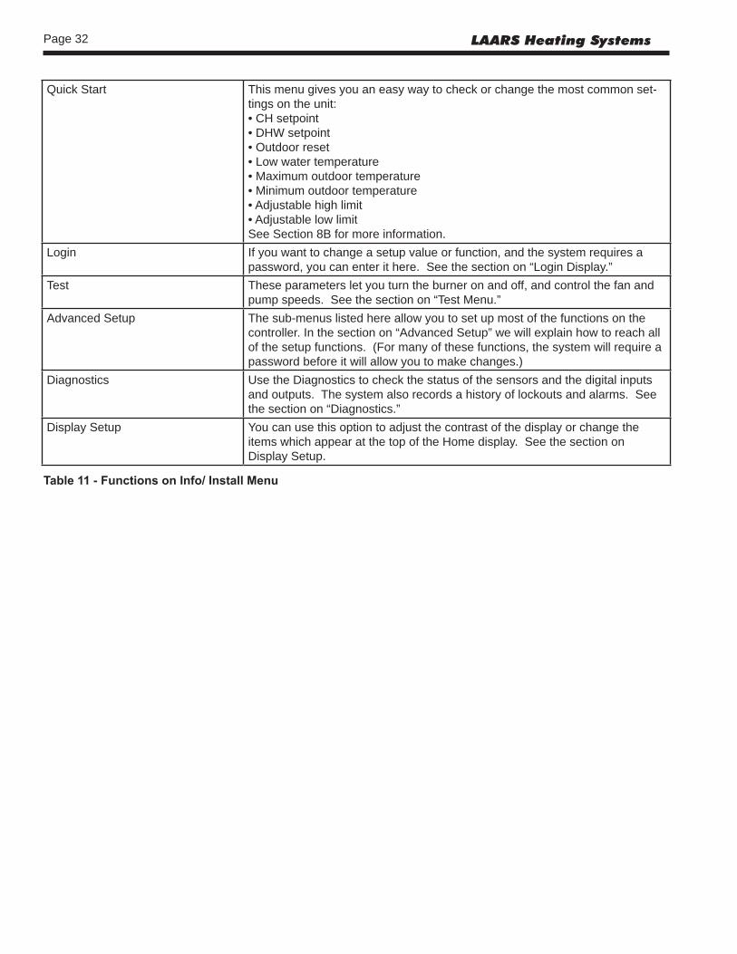
Quick Start This menu gives you an easy way to check or change the most common set-tings on the unit:• CH setpoint• DHW setpoint• Outdoor reset• Low water temperature• Maximum outdoor temperature• Minimum outdoor temperature• Adjustable high limit• Adjustable low limitSee Section 8B for more information.
Login If you want to change a setup value or function, and the system requires a password, you can enter it here. See the section on “Login Display.”
Test These parameters let you turn the burner on and off, and control the fan and pump speeds. See the section on “Test Menu.”
Advanced Setup The sub-menus listed here allow you to set up most of the functions on the controller. In the section on “Advanced Setup” we will explain how to reach all of the setup functions. (For many of these functions, the system will require a password before it will allow you to make changes.)
Diagnostics Use the Diagnostics to check the status of the sensors and the digital inputs and outputs. The system also records a history of lockouts and alarms. See the section on “Diagnostics.”
Display Setup You can use this option to adjust the contrast of the display or change the items which appear at the top of the Home display. See the section on Display Setup.
Table11-FunctionsonInfo/InstallMenu
Page 33NEOTHERM Boilers and Water Heaters
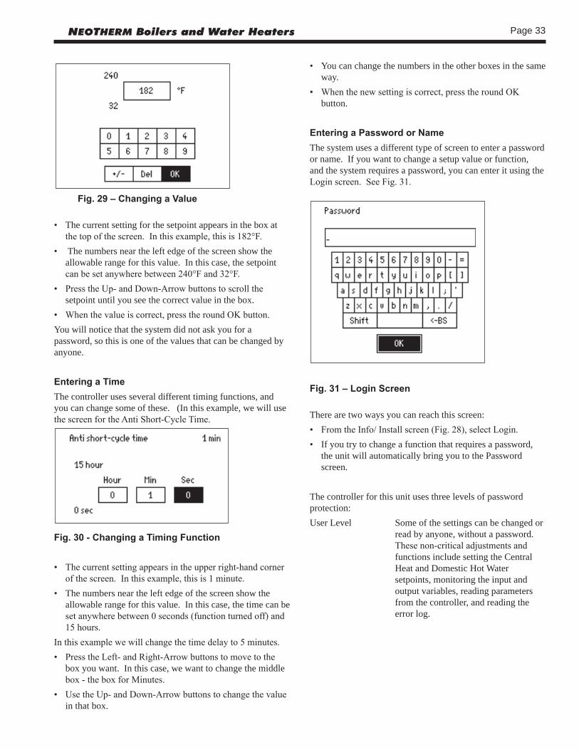
Fig.29–ChangingaValue
• The current setting for the setpoint appears in the box at the top of the screen. In this example, this is 182°F.
• The numbers near the left edge of the screen show the allowable range for this value. In this case, the setpoint can be set anywhere between 240°F and 32°F.
• Press the Up- and Down-Arrow buttons to scroll the setpoint until you see the correct value in the box.
• When the value is correct, press the round OK button.You will notice that the system did not ask you for a password, so this is one of the values that can be changed by anyone.
EnteringaTimeThe controller uses several different timing functions, and you can change some of these. (In this example, we will use the screen for the Anti Short-Cycle Time.
Fig.30-ChangingaTimingFunction
• The current setting appears in the upper right-hand corner of the screen. In this example, this is 1 minute.
• The numbers near the left edge of the screen show the allowable range for this value. In this case, the time can be set anywhere between 0 seconds (function turned off) and 15 hours.
In this example we will change the time delay to 5 minutes.• Press the Left- and Right-Arrow buttons to move to the
box you want. In this case, we want to change the middle box - the box for Minutes.
• Use the Up- and Down-Arrow buttons to change the value in that box.
• You can change the numbers in the other boxes in the same way.
• When the new setting is correct, press the round OK button.
EnteringaPasswordorNameThe system uses a different type of screen to enter a password or name. If you want to change a setup value or function, and the system requires a password, you can enter it using the Login screen. See Fig. 31.
Fig.31–LoginScreen
There are two ways you can reach this screen:• From the Info/ Install screen (Fig. 28), select Login.• If you try to change a function that requires a password,
the unit will automatically bring you to the Password screen.
The controller for this unit uses three levels of password protection:User Level Some of the settings can be changed or
read by anyone, without a password. These non-critical adjustments and functions include setting the Central Heat and Domestic Hot Water setpoints, monitoring the input and output variables, reading parameters from the controller, and reading the error log.

Page 34 LAARS Heating Systems
Installer Level Settings that might affect the safe operation of the unit can only be changed by a trained technician who enters a password. These include setup and parameter changes made when the system is installed, and some diagnostic and troubleshooting functions. The installer level password is “lnt” (lower case “LNT”).
OEM Level Some of the settings can only be changed at the Laars factory.
Once you enter a password, the password access remains valid until you exit to the normal no-password state. If you do not make any edits for 10 minutes, the password access will be cancelled.The areas on the Login display are arranged a bit like a computer keyboard.• To enter a letter or number, use the Up-, Down-, Left- and
Right-Arrow buttons to highlight the character you want to use, then press the round OK button. You will see the character appear in the line at the top of the screen.
• Notice that, in the example shown here, all of the letters are lower-case (not capitals). If you want to use an upper-case letter, first move to the area for Shift and press the round OK button. Now, any letters that you enter will appear as capitals. To go back to lower-case letters, go back to the area for Shift and press the round OK button again.
• The blank area at the bottom of the screen is a space bar.• The “BS” (BackSpace) area acts as a delete key. To delete
a letter, move down and highlight the “BS” area. Now, each time you press the round OK button, the system will delete one character from the right end of the line.
• When the characters in the line at the top of the screen are correct, move to the OK space at the bottom of the screen, and press the round OK button. This will send the new “string” of characters to the controller.
TurningaFunctionOnandOffSome of the values can be enabled or disabled. See the example below.
Fig.32-Enable/DisableScreen
• Use the Up- and Down-Arrows to highlight the line you want, then press the round OK button.
ChangingaValueUsinga“Slider”There is another type of control screen you may see. This type of screen uses a “slider” to set the value. This system is used on the LCD Contrast screen (available under Display Setup.) See Fig. 33.
Fig.33–ChangingLCDContrast
• Use the Left- and Right-Arrow buttons to move the bar and adjust the contrast.
• When the setting is correct, press the round OK button.

Page 35NEOTHERM Boilers and Water Heaters
Section 8A -QUICK START MENU
Section 8 is divided into three parts. Section 8A includes instructions for using the Quick Start Menu. Section 8B covers basic installation and wiring. Section 8C includes more detailed setup instructions and wiring diagrams.
Fig.35-QuickStartMenu
.ChangingtheCH(CentralHeat)Setpoint-
Fig.36-ChangingtheCHSetpoint
• On the Quick Start menu, use the Up- and Down-Arrows to go to the line for CH Setpoint. Press the large OK button to select the line.
• Use the Up- and Down-Arrow buttons to select the value you want.
• Press the round OK button to enter the new value.
ChangingtheDHW(DomesticHotWater)Setpoint-See the procedure described above for the CH setpoint.
Outdoor Reset Functions -The next four lines in the display are used to set up the Outdoor Reset functions:• Outdoor Reset Enable/Disable - Note: This function can
be Enabled/Disabled only by a factory trained technician. • Low Water Temperature - Use the Up- and Down-Buttons
to select the function, use Up- and Down- to select the new value, then press the round OK button.
• Maximum Outdoor Temperature - Use the Up- and Down-Buttons to select the function, use Up- and Down- to select the new value, then press the round OK button.
• Minimum Outdoor Temperature - Use the Up- and Down-Buttons to select the function, use Up- and Down- to select the new value, then press the round OK button.
For a complete explanation of the setup for Outdoor Reset, see Section 8C.5.
AdjustableHighLimit-The absolute high limit setting for the water outlet temperature for this unit is set at the factory to 195°F (90.5°C). If you wish, you can also set a second or “adjustable” limit setting that is lower.Use the Up- and Down-Buttons to select the function, use Up- and Down- to select the new value, then press the round OK button.
AdjustableStackLimit-The absolute high limit setting for the stack for this unit is set at the factory to 195°F (90.5°C). If necessary, you can set the unit to use a second or “adjustable” limit setting that is lower. Use the Up- and Down-Buttons to select the function, use Up- and Down- to select the new value, then press the round OK button.

Page 36 LAARS Heating Systems
Section 8B -BASIC INSTALLATION AND WIRING
Section 8 is divided into three parts. Section 8A includes instructions for using the Quick Start Menu. Section 8B covers basic installation and wiring. Section 8C includes more detailed setup instructions and wiring diagrams.
8B.1 InstallationWarnings
Single pole switches, including those of safety controls and protective devices, must not be wired in a grounded line.
All electrical connections are made on the terminal blocks that are located inside the control panel. Wiring connections are shown in Figure 34.
All internal electrical components have been prewired. No attempt should be made to connect electrical wires to any other location except the terminal blocks.
WARNINGThe appliance must be electrically grounded in accordance with the requirements of the authority having jurisdiction or, in the absence of such requirements, with the latest edition of the National Electrical Code, ANSI/NFPA 70, in the U.S. and with the latest edition of CSA C22.1 Canadian Electrical Code, Part 1, in Canada. Do not rely on the gas or water piping to ground the metal parts of the boiler. Plastic pipe or dielectric unions may isolate the boiler electrically. Service and maintenance personnel, who work on or around the boiler, may be standing on wet floors and could be electrocuted by an ungrounded boiler. Electrocution can result in severe injury or death.
Figure34-ControlPanelLayout

Page 37NEOTHERM Boilers and Water Heaters
CautionThe supply voltage to the NeoTherm unit must not be disconnected, except for service or isolation, or unless otherwise instructed by procedures outlined in this manual. To signal a call for heat, use the 24V field interlock, as shown in the wiring diagram.
DO NOT MAKE AND BREAK THE LINE VOLTAGE TO THE NEOTHERM UNIT TO SIGNAL A CALL FOR HEAT. A call for heat/ end call for heat MUST be connected to the field interlock terminals. Some NeoTherm components are designed to have constant voltage during normal operation. If the NeoTherm’s supply voltage is toggled as a call for heat signal, premature failure of these components may result.
The NeoTherm unit does not recognize 4mA as a signal to shut off. If the call for heat is not connected between the field interlock terminals, the NeoTherm will remain in low fire when it sees 4mA as a modulating signal.
8B.2 MainPowerConnectionsConnect a 15A fused, 120-volt supply to the main power switch. (The hot leg is connected directly to the switch.) The neutral leg is connected directly to the white wire. The ground wire can be connected to the grounding lug on the control panel. (See Fig. 34.)
8B.3 PumpConnectionsandOperationThe controller in the NeoTherm energizes the pump contacts when it receives a call for heat. Once the call for heat is satisfied, the pump will remain on for the defined pump overrun time.The Boiler Pump terminals (TB5 - max 7.4 FLA) are fed by 120V (violet wire) internally from the main power feed. The System and DHW contacts are dry contacts. Appropriate voltage must be supplied to the System and DHW pumps for proper operation. The System pump connections are located on terminal block 5 (TB5) in the control panel. (See Figure 34.) The System pump contacts are rated for 120Vac, 7.4 Amps. To use the contacts, power must be supplied on one terminal with the other terminal wired to the pump or a relay controlling the pump.The DHW pump connections are located on terminal block 5 (TB5) in the control panel and are rated for 120Vac, 7.4 Amps. To use the contacts, power must be supplied on one terminal, and the other terminal wired to the pump or a relay controlling the pump.
Additional 120VAC circuits may be required for the pumps.Once the unit has been installed and set up, the Quick Start menu provides a simple way to change the most common settings used in a typical installation. (If your installation is more complex, refer to Section 8C.) To reach the Quick Start menu, press the “I” button (“Info/Install”), then press the Quick Start menu item.
WATER HEATER
SIZES VOLTS PHASE AMPS
150-500 120 Single 2* No pump
150-199 120 Single 7* With pump
285-500 120 Single 8* With pump
600-850 See Pump Rating Plate FLA No pump (must be less than 7.4 FLA)*Minimum 15A circuit required
Table13-NTVElectricalData
BOILER PUMP CONNECTIONS RATINGS SIZES VOLTS PHASE AMPS (Boiler, System Pump and
DHW Pump Connections)
80–850 120 Single 2* 115V – Maximum 1HP No Pump or 7.4A max
80-500 Less With Pump 120 Single than 115V – Maximum 1HP
6* or 7.4A max
*Minimum 15A circuit required
Table12-NTHElectricalData

Page 38 LAARS Heating Systems
8C.1 24VACTransformer withIntegralCircuitBreaker24Vac is supplied by a transformer mounted underneath the control panel. All 24Vac power is supplied through a circuit breaker that is part of the transformer. The transformer is then connected to terminal blocks 3 and 4 (TB3 and TB4).
8C.2 HydronicHeatingDemandWhen using the NeoTherm for hydronic heating, a call for heat must be supplied to the “T-T or Interlock” terminal. Once the call is supplied, the control starts the Boiler and System pumps, and begins the ignition process. The ignition process consists of a prepurge, trial for ignition, and run period. The prepurge period starts on a call for heat once the fan RPM reaches a preset level. The trial for ignition period follows once the start-up RPM of the fan has been reached. The trial for ignition period lasts four seconds, During this period the direct spark ignition system and gas valve are energized. At the end of the trial for ignition period, the flame signal is compared with the preset flame threshold value. If the flame signal is higher than the flame threshold, the NeoTherm enters Run. If the flame signal is below the threshold, the NeoTherm returns to prepurge and starts the ignition process over. When operating in Run, the NeoTherm monitors the flame signal, call for heat input, safety switches, and water temperatures and modulates as needed between 100% and 20% of rate to satisfy the call for heat.Connect the call for heat to terminal block 7 (TB7), connections labeled “T-T or interlock” in the control panel.The CH Setpoint can be set from the Quick Start menu.
How to get there: From the “Home” screen, press “I” to go to “Info/ Install.” Choose “Quick Start,” then go to “CH Setpoint.”
8C.3 Anti-Short-Cycle(ASC)The anti short cycle function helps to prevent short-cycling when the call for heat switches on and off quickly. To reach the anti-short-cycle function, select Info/ Advanced Setup/ System Config./ System Config.
How to get there: From the “Home” screen, press “I” to go to “Info/ Install.” Choose “Advanced Setup,” then “System Configuration,” then “System Configuration” again.
8C.4 OutdoorAirTemperatureSensorThe outdoor air temperature sensor is used with the Outdoor Reset and Warm Weather Shutdown functions.Connect the outdoor air temperature sensor to terminal block 7 (TB7), using the connections labeled Outdoor Temp Sensor.
8C.5 Outdoor ResetAbout Outdoor Reset -The Outdoor Reset feature calculates a correction for the hydronic (Central Heat) setpoint depending on the outdoor temperature. This allows the system to compensate for changes in the outdoor temperature and run more efficiently. (If the unit will operate as part of a Lead/Lag system, the Outdoor Reset function will adjust the Lead/Lag setpoint. For details, see “About Lead/Lag Operation” - Section 8C.8.)The graph below shows how the system will behave at different outdoor temperatures:
22 27 32 37 42 47 52 57 62 67 72 7790
100
110
120
130
140Setpoint
Outdoor Temperature °F
Fig.37–OutdoorResetOperation
In the graph shown above, the sloping line shows the setpoint which is actually used by the system. Without Outdoor Reset, this would be a constant 130°F (or whatever other value you choose), regardless of the outdoor temperature. The line in the graph would run straight across the display. However, with the Outdoor Reset feature turned on, the system will adjust for changes in the outdoor temperature. Let’s take a detailed look at the way the setpoint is adjusted. • For cold outdoor temperatures (below 32°F), the setpoint
remains unchanged (130°F).
Section 8C -DETAILEDSETUPINSTRUCTIONSandDIAGRAMS
Section 8 is divided into three parts. Section 8A includes instructions for using the Quick Start Menu. Section 8B covers basic installation and wiring. Section 8C includes more detailed setup instructions and wiring diagrams.

Page 39NEOTHERM Boilers and Water Heaters
• As the temperature begins to rise above 32°F, the Outdoor Reset function causes the setpoint to be lowered. At these warmer temperatures, the heating load on the system is not as great, so the system does not have to reach as high a temperature to handle the load.
• As you can see from the display, at an outdoor temperature of about 70°F, the system stops adjusting the setpoint. Above 70°F, the setpoint is constant at 100°F (or another value that you choose).
When Outdoor Reset is enabled, and the outdoor temperature falls between the maximum and minimum outdoor temperatures (70° and 32° in the example above), the setpoint will be adjusted down by about .8° for every 1° increase in the outdoor temperature (See Figure 37). For example, if the outdoor temperature rises by 10°, the Outdoor Reset function will adjust the setpoint down by about 5°. This ratio between outdoor temperature and water temperature is adjustable.
Here are instructions for setting up the Outdoor Reset function. Notice that these instructions will be different, depending on whether you have a single boiler or more than one boiler (using Lead/Lag operation).
Wiring Connections -Connect the outdoor temperature sensor:
If your system has just one boiler –Connect the sensor across terminals 1 and 2 on TB-7.If your system has more than one boiler, and is controlled using the Lead/ Lag function –Connect the sensor across terminals 1 and 2 on TB-7 on the boiler which will be used as the Lead/Lag Master.
Setting Up the Control Functions -1. Enable the Outdoor Reset function:
Note: This function can be Enabled/Disabled only by a factory trained technician.
2. Set the maximum outdoor temperature: If the outdoor temperature reaches this value or above, the system will use the Low Water Temp value as the setpoint. In the example shown earlier, the Max. Outdoor Temp. is set to 70°F. If the outdoor temperature rises above 70°F, the system will use 100°F (the Low Water Temp.) as the setpoint.
If your system has just one boiler –How to get there: From the “Home” screen, press “I” to go to “Info/ Install.” Choose “Advanced Setup,” then go to “CH Configuration.” Select “Outdoor Reset Configuration.” Set the value on the line for “Max. Outdoor Temp.”If your system has more than one boiler, and is controlled using the Lead/ Lag function –How to get there: From the “Home” screen, press “I” to
go to “Info/ Install.” Choose “Advanced Setup,” then go to “Lead/ Lag Configuration.” Select “Lead/ Lag Outdoor Reset.” Set the value on the line for “Max. Outdoor Temp.”
3. Set the minimum outdoor temperature:If the outdoor temperature drops to this value or below, the system will not compensate for the outdoor temperature. In the example shown earlier, the Min. Outdoor Temp. is set to 32°F. If the outdoor temperature is below 32°F, the system will use the normal system setpoint (130°F in this example).
If your system has just one boiler –How to get there: From the “Home” screen, press “I” to go to “Info/ Install.” Choose “Advanced Setup,” then go to “CH Configuration.” Select “Outdoor Reset Configuration.” Set the value on the line for “Min. Outdoor Temp.”If your system has more than one boiler, and is controlled using the Lead/ Lag function –How to get there: From the “Home” screen, press “I” to go to “Info/ Install.” Choose “Advanced Setup,” then go to “Lead/ Lag Configuration.” Select “Lead/ Lag Outdoor Reset.” Set the value on the line for “Min. Outdoor Temp.”
4. Set the low water temperature:If the outdoor temperature reaches the Max. Outdoor Temp. or higher, the system will use the Low Water Temp value as the new setpoint. In the example shown earlier, the Max. Outdoor Temp. is set to 70°F. If the outdoor temperature reaches 70°F or above, the system will use the Low Water Temp. value (example - 100°F) as the setpoint.
If your system has just one boiler –How to get there: From the “Home” screen, press “I” to go to “Info/ Install.” Choose “Advanced Setup,” then go to “CH Configuration.” Select “Outdoor Reset Configuration.” Set the value on the line for “Low Water Temp.”If your system has more than one boiler, and is controlled using the Lead/ Lag function –How to get there: From the “Home” screen, press “I” to go to “Info/ Install.” Choose “Advanced Setup,” then go to “Lead/ Lag Configuration.” Select “Lead/ Lag Outdoor Reset.” Set the value on the line for “Low Water Temp.”
5. Set the minimum boiler water temperature:If a value is entered here, the temperature in the boiler will never be allowed to drop below this temperature. This will protect the boiler against possible damage due to expansion of ice inside the unit. (Notice that this is different from the “low water temperature” described above.)
If your system has just one boiler –How to get there: From the “Home” screen, press “I” to go to “Info/ Install.” Choose “Advanced Setup,”

Page 40 LAARS Heating Systems
then go to “CH Configuration.” Select “Outdoor Reset Configuration.” Set the value on the line for “Min. Boiler Water Temp.”If your system has more than one boiler, and is controlled using the Lead/ Lag function –How to get there: From the “Home” screen, press “I” to go to “Info/ Install.” Choose “Advanced Setup,” then go to “Lead/ Lag Configuration.” Select “Lead/ Lag Outdoor Reset.” Set the value on the line for “Min. Water Temp.”
8C.6 WarmWeatherShutdownAbout Warm Weather Shutdown -The Warm Weather Shutdown feature tells the unit to stop firing if the outdoor temperature rises above a temperature you set. Notice that this affects the central heat or hydronic function only. If a call for domestic hot water arrives, the unit will still fire and respond to that. Warm Weather Shutdown requires the connection of an outdoor temperature sensor. See Section 8C.4. (If Outdoor Reset is active, the same sensor can be used for both functions.)Here are instructions for setting up the Warm Weather Shutdown function. Notice that these instructions will be different, depending on whether your system has a single boiler or more than one boiler (using Lead/Lag operation).
Wiring Connections -Connect the outdoor temperature sensor.:If your system has just one boiler –Connect the sensor across terminals 1 and 2 on TB-7.If your system has more than one boiler, and is controlled using the Lead/ Lag function –Connect the sensor across terminals 1 and 2 on TB-7 on the boiler which will be used as the Lead/Lag Master.
Setting Up the Control Functions -1. Enable the Warm Weather Shutdown function:
If your system has just one boiler –How to get there: From the “Home” screen, press “I” to go to “Info/ Install.” Choose “Advanced Setup,” then go to “CH Configuration.” Select “Warm Weather Shutdown.” On the line for “Warm Weather Shutdown,” select “Immediately.”If your system has more than one boiler, and is controlled using the Lead/ Lag function –How to get there: On the unit used as the Lead/ Lag Master only - From the “Home” screen, press “I” to go to “Info/ Install.” Choose “Advanced Setup,” then go to
“CH Configuration.” Select “Warm Weather Shutdown.” On the line for “Warm Weather Shutdown,” select “Immediately.”
2. Enter the setpoint for this feature: If your system has just one boiler –How to get there: From the “Home” screen, press “I” to go to “Info/ Install.” Choose “Advanced Setup,” then go to “CH Configuration.” Select “Warm Weather Shutdown.” Go to the line for “Warm Weather Shutdown Setpoint”, and set the value.If your system has more than one boiler, and is controlled using the Lead/ Lag function –How to get there: On the unit used as the Lead/ Lag Master only - From the “Home” screen, press “I” to go to “Info/ Install.” Choose “Advanced Setup,” then go to “CH Configuration.” Select “Warm Weather Shutdown.” On the line for “Warm Weather Shutdown Setpoint,” and set the value.
8C.7 DomesticHotWaterA NeoTherm unit can be configured to supply domestic hot water (DHW) as a stand-alone “volume” unit (DHW models) or as a secondary function while the unit also provides hydronic heating. The piping used to supply domestic hot water (DHW) can be set up in several different ways. See Section 6 for details. In this section, we will describe the wiring and control setup for several different types of DHW supplies.
DANGER• Water temperature over 125°F (52°C) can cause
severe burns instantly or death from scalds.• Children, disabled and elderly are at hightest risk of
being scalded.• Set the water temperature carefully as described
below.• Feel the water before bathing or showering.• If this appliance is used to produce water that could scald if too hot, such as domestic hot water use, adjust the outlet control (limit) or use temperature limiting valves to
obtain a maximum water temperature of 125°F (52°C).

Page 41NEOTHERM Boilers and Water Heaters
DHW Temperature Setting -Regardless of the type of DHW setup, the setpoint adjustment is made the same way.
How to get there: From the “Home” screen, press “I” to go to “Info/ Install.” Choose “Advanced Setup,” then go to “DHW Setpoint.”
Hydronic Heating withDomestic Hot Water (DHW) Priority -When using the NeoTherm for hydronic heating with domestic hot water priority, a call for heat must be supplied to the “T-T or Interlock” terminal. Once the call is supplied, the control starts the Boiler and System pumps and begins the ignition process. Once in Run, the NeoTherm monitors the flame signal, call for heat, safeties, and water temperatures modulating as needed between 100% and 20% of rate to satisfy the call for heat. When a DHW demand is applied during a hydronic call for heat, the priority feature forces the boiler to switch to the DHW demand for the priority time. The DHW priority demand forces the control to operate to the DHW setpoint, de-energizes the System pump and energizes the DHW pump.The domestic hot water temperature sensor or an aquastat is used to monitor the DHW demand. The control uses the DHW sensor to control the operation and modulation rate of the appliance when there is a DHW demand.
Domestic Hot Water Demand - NTV only -The “NTV” NeoTherm units are designed to provide “volume water” DHW in conjunction with a storage tank. When the NTV model NeoTherm is used in this application, a call for heat must be supplied to the “DHW stat” terminal located on terminal block 6 (TB6). The DHW heating call can be from the supplied DHW sensor or from an aquastat. If the DHW sensor is used, the heater operates to maintain the temperature at the DHW sensor. (This may allow the actual heater outlet water temperature to exceed the DHW sensor setpoint.) If an aquastat is used to supply the DHW demand, the heater’s firing rate is controlled by the DHW setpoint temperature and the water temperature at the heat exchanger outlet.When the unit receives the DHW call, the control starts the Boiler and DHW pumps and begins the ignition process. Once in Run, the NeoTherm monitors the flame signal, call for heat, safeties, and water temperatures modulating as needed between 100% and 20% of rate to satisfy the call for heat.
Hydronic Heating Using Local Lead-Lag/Cascading Feature with Indirect Hot Water -(For a complete explanation of the Lead/Lag system, see Section 8C.8.)When using the Lead/Lag boiler system to provide indirect domestic hot water heating, the DHW demand should be supplied to the Master boiler through the existing DHW terminals. The Lead/Lag system will change the operating mode of just the Master boiler to supply water at the DHW setpoint. The remaining boilers on the system will continue to supply hydronic heating.When the system is supplying both hydronic heat and domestic hot water at the same time, both the System pump and DHW pump contacts are closed, so special attention must be paid to allow for proper operation. In applications serving both hydronic and domestic heating, during a DHW call the Boiler pump on the Master boiler may need to be turned off. The DHW pump will provide flow through the boiler and indirect tank when there is a DHW call. (This means the DHW pump must be sized properly.) To turn off the boiler pump in this application, the “boiler pump interrupt” jumper must be installed. The terminal block location is terminal block 5 (TB5) at the contacts labeled “boiler pump interrupt” in the control panel.
Sensor Connection for Domestic Hot Water -Connect the DHW sensor or aquastat.
If your system has just one boiler –Connect the sensor across terminals 5 and 6 on TB6.If your system has more than one boiler, and is controlled using the Lead/ Lag function –On the unit used as the Lead/ Lag Master only, connect the sensor across terminals 5 and 6 on TB6.
Domestic Hot Water HeatingUsing External Modulation Control -When the NeoTherm is used for DHW heating with external modulation control, a call for heat must be supplied to the “T-T or Interlock” terminal. By supplying a call to the “T-T or interlock” terminal, the operating temperature setpoint defaults to the hydronic heating setpoint, so all of the tem-perature adjustments must be made to the hydronic setpoint. When the unit receives the call, the control starts the Boiler and System pumps and begins the ignition process. Once in Run, the NeoTherm monitors the flame signal, call for heat, safeties, and water temperatures. The heater setpoint is used to limit the maximum water temperature leaving the boiler only. The modulation rate is controlled by a 4-20mA signal supplied by an external control. (This can also be 0-10Vdc us-ing a converter.) When setting up a system using an external control, take care to set Anti-Short Cycle feature to prevent “hunting “ and possible premature component failure.

Page 42 LAARS Heating Systems
Boiler Pump Interrupt Function -
The Boiler pump interrupt feature is used in some applications when the boiler is being used for both hydronic and domestic hot water heating. The interrupt jumper is used to turn off the boiler pump during a domestic hot water demand. For this to work properly the system must be plumbed and pumped to allow the DHW pump to supply the flow and head requirements for both the boiler and indirect water heater. It is not necessary to use the interrupt jumper in all applications.To turn off the Boiler pump in this situation, the “boiler pump interrupt” jumper should be installed between R1 and R2 on TB5.If your system includes several boilers, is controlled using the Lead/Lag system, and the indirect DHW tank is connected to the boiler acting as the Lead/Lag master, install the boiler interrupt jumper on the Lead/Lag master only.
WARNINGFailure to plumb, pump and install the appliance correctly when using this feature may lead to reduced or no water flow through the heat exchanger, causing premature failure of the heat exchanger, personal injury or death. Please consult the factory with any questions regarding the use of this feature.
Setup for DHW Control Functions -1. Set up the correct priority for the DHW function in relation
to Central Heat or Lead/ Lag demands. If a call for heat and a DHW demand arrive at the same time, which will have the higher priority?If your system has just one boiler –How to get there: From the “Home” screen, press “I” to go to “Info/ Install.” Choose “Advanced Setup,” then go to “DHW Configuration.” Select “DHW Priority vs Central Heat.”If your system has more than one boiler, and is controlled using the Lead/ Lag function –How to get there: On the unit used as the Lead/Lag Master, from the “Home” screen, press “I” to go to “Info/ Install.” Choose “Advanced Setup,” then go to “DHW Configuration.” Select DHW Priority vs Lead/Lag.”
2. Set the setpoint for the DHW function.If your system has just one boiler –How to get there: From the “Home” screen, press “I” to go to “Info/ Install.” Choose “Advanced Setup,” then go to “DHW Configuration.” Select “DHW Setpoint.”If your system has more than one boiler, and is controlled using the Lead/ Lag function –How to get there: On the unit used as the Lead/Lag Master, from the “Home” screen, press “I” to go to “Info/ Install.” Choose “Advanced Setup,” then go to “DHW Configuration.” Select “DHW Setpoint.”
3. Set the DHW priority time. If the DHW function has the priority, the priority will continue during the priority time.If your system has just one boiler –How to get there: From the “Home” screen, press “I” to go to “Info/ Install.” Choose “Advanced Setup,” then go to “DHW Configuration.” Select “DHW Priority Time.”If your system has more than one boiler, and is controlled using the Lead/ Lag function –How to get there: On the unit used as the Lead/Lag Master, from the “Home” screen, press “I” to go to “Info/ Install.” Choose “Advanced Setup,” then go to “DHW Configuration.” Select “DHW Priority Time.”
8C.8 CascadingLead/LagOperationAbout Lead/Lag Operation -If an installation includes two or more boilers, they may be set up for “Lead/Lag” operation. One boiler will be set up as the “Master”, and the others will operate as “Slaves.” Figure 38 shows an installation with four boilers. (A Lead/Lag system can include up to eight boilers.) The boiler controllers are connected in a “daisy chain” using a Modbus connection. See Fig. 40.A single System sensor is used to monitor the demand for heat. The input from this sensor is used by the Master controller to control the modulation rates of all of the operating boilers.
Lead/Lag Modulation Cycle -Note - We will explain the modulation cycle here, in case you need to understand how the Lead/Lag system actually operates. If you are installing the unit(s) and want to skip this section, just remember that, as the heating demand increases, the Lead/Lag system puts more boilers on-line. As the heating demand is reduced, the Lead/Lag system shuts off some of the boilers.The signal from the System sensor is sent to the unit operating as the Lead/Lag Master. A Run sequence is initiated when the system temperature falls to the Lead/Lag Central Heat setpoint. (Actually this is the LL CH setpoint less the On Hysteresis value. The default setting for On Hysteresis is 5°F, but this is adjustable.)
NOTE: If your NeoTherms are Lead / Lag configured, you will find it very useful to customize your Home Display to show LL Operating Temp and LL Setpoint Temp. Please refer to Section 7.5 to learn how to customize your Home Display. Various parameters can be displayed on the Home Display to suit your needs.

Page 43NEOTHERM Boilers and Water Heaters
Notice that, when a boiler is operating as part of a Lead/Lag system, it does not use the normal CH setpoint – it uses the special LL CH setpoint on the Lead/Lag Master. The unit acting as the Lead/Lag Master decides which boiler is assigned to start first. This assignment is rotated across all of the available boilers so that any one boiler does not run significantly longer than the others. The Lead/Lag controller tracks the run times for all of the boilers, and uses this to calculate the starting order for the boilers. This means that each time the system starts up, a different boiler may start first. • When the Run sequence is initiated, the boiler with the
least amount of runtime will fire.• If the heating demand increases so that the firing rate
of that first boiler rises to your boiler configurations Base Load Value (see Table 14), the next boiler in the sequence will start up and begin firing at 20 to 35% fan speed (depending on your configuration). After this, the entire configuration of boilers will modulate up or down together, in reaction to the changes in demand. See Figures 39A, 39B, and 39C.
Control Settings for Lead/Lag System - Part 11. Power up all of the boilers in the system.2. In an installation with several boilers, you can give each
boiler a different name. On each unit, go to the screen for “System ID and Access,” and enter a unique name.
How to get there: From the “Home” screen, press “I” to go to “Info/Install” Choose “Advanced Setup,” then go to “System Configuration,” then “System ID and Access,” and select “Boiler Name.”
3. The controller in each of the boilers needs a unique “Modbus address” so the Lead/Lag Master can communicate with it. All of the units come from the factory with a Modbus address of “1,” so you will need to change some of these addresses. The unit operating as the Lead/Lag Master should have address “1,” and the other boilers should each have unique Modbus address numbers.
Display
Boiler 1 Boiler 2 Boiler 3 Boiler 4
Controller
Burner
Fig.38–“Lead/Lag”OperationinaSystemwithFourBoilers.Note - the Displays on Boilers 2 thru 4 will display information pertaining only to that specific boiler.
Number of boilers installed
Base load value
1 NA2 65%3 50%4 35%5 35%6 35%7 35%8 35%
Table14-BaseLoadSettings
Fig.39A-Lead/LagOperation,2boilers.
Low demand -The first boiler insequence fires atless than 65%
Firstboiler
Secondboiler
Demand increases -Once the first boilerreaches 65%, the second boiler switches on, andboth modulatetogether between 20%and 65%
Nearing max. demand -Once both reach 65%, then they are both allowed to go over65%

Page 44 LAARS Heating Systems
CautionYou should set the Modbus addresses before you connect the Modbus wiring. If the wiring is attached before the Modbus addresses on the controls are changed, there will be multiple controls with the same address, and the system will not work.
WARNINGIf the Modbus addresses are not assigned properly, the system could fail to operate correctly, or it might operate in an unsafe manner. This could lead to property damage, personal injury or death.
How to get there: On each boiler: From the “Home” screen, press “I” to go to “Info/Install.” screen. Choose “Advanced Setup,” then select “System Configuration”. Then select “System ID & Access,” and select “MB1 Modbus Address.” Change it to its new unique Modbus address ( 1-8), then select “MB2 Modbus Address” and change it to the same address as the changed “MB1 Modbus Address” DO NOT CHANGE THE MENU LINE “ModBus Address”. It will
automatically change when you change the “MB1 Modbus Address” 4. The next job is to identify each boiler as a Lead/Lag
Master or Slave.• On the boiler that will be used as the Lead/Lag Master,
identify the unit that will operate as the master by turning on “Master Enable.”
How to get there: From the “Home” screen, press “I” to go to “Info/Install.” Choose “Advanced Setup,” then go to “Lead/ Lag Configuration.” Select “Lead Lag Master Configuration.” On the line for “Master Enable,” select “Enable.”
• On all of the boilers (including the Lead/Lag Master), identify each unit as a slave by turning on “Slave Enable.”
How to get there: From the “Home” screen, press “I” to go to “Info/Install.” Choose “Advanced Setup,” then go to “Lead/ Lag Configuration”. Select “Lead Lag Slave Configuration.” On the line for “Slave Enable” select “Enable.” When you select Slave Enable these options will be displayed “Enable via Modbus Master” or “Enable via Sola Master”. Choose “Enable via Sola Master”.
Fig.39B-Lead/LagOperation,3boilers. Fig.39C-Lead/LagOperation,4ormoreboilers.
Low demand -The first boiler insequence fires atless than 35%
Firstboiler
Secondboiler
Thirdboiler
Fourthboiler
Demand increases -Once the first boilerreaches 35%, the second boilerswitches on, andboth modulatetogether between 20%and 35%
Demand increases -Once the first two boilers reach 35%, the third boilerswitches on, and all three modulate togetherbetween 20% and 35%
Nearing max. demand -The fourth boiler is active. Once all four reach 35%, all are allowed to go over35%
* - The Lead/Lag controller will change the firing order of the boilers, based on the run time of each burner.
Low demand -The first boiler insequence fires atless than 50%
Firstboiler
Secondboiler
Thirdboiler
Demand increases -Once the first boilerreaches 50%, the second boiler switches on, andboth modulatetogether between 20%and 50%
Demand increases -Once the first two boilers reach 50%, the third boilerswitches on, and all three modulate togetherbetween 20% and 50%
Nearing max. demand -Once all three reach50%, then all three are allowed to go over50%
* - The Lead/Lag controller will change the firing order of the boilers, based on the run time of each burner.

Page 45NEOTHERM Boilers and Water Heaters
Wiring Connections for Lead/Lag - Now you can make the Modbus wiring connections
between the units. The controller in each boiler includes two wiring terminals for the Modbus system, labeled “MB1” and “MB2.” MB1 has the wiring connections to the User Interface display on each unit, and MB2 is used to communicate with the other boilers in the Lead/Lag system. See Fig. 40.
To reach the controller, open the cabinet of the boiler by removing the plastic bezel.
The wiring from the controller on the first boiler runs to the controller on the next boiler. Use 22 AWG or thicker shielded twisted-pair wire with drain. Two twisted pairs or three conductors are needed. Wire A on MB2 of Boiler 1 must be connected to A on MB2 of Boiler 2, wire B on Boiler 1 goes to B on Boiler 2, and wire C on Boiler 1 goes to C on Boiler 2. Repeat this wiring for any other boilers in the system. Connect all of the drain wires and ground the drain wire on one end of the assembly only.
Control Settings for Lead/Lag System - Part 21. On the Lead/Lag Master, set the setpoint used by the Lead/
Lag system. How to get there: From the “Home” screen, press “I” to
go to “Info/Install.” Choose “Advanced Setup,” then go to “Lead/ Lag Configuration.” Select “Lead Lag Master Configuration,” and go to the line for “Setpoint.”
2. On the Lead/Lag Master, set the Base Load to match the number of boilers in the system. We mentioned the Base Load setting in the explanation of the “Lead/Lag Modulation Cycle.” Whenever the heating demand causes the active burner(s) to run faster than the Base Load value, the Lead/Lag system will put an additional burner on line. The Base Load value depends on the number of boilers in the system:
Note that you only need to enter the Base Load value on the Lead/Lag Master. How to get there: From the “Home” screen, press “I” to
go to “Info/Install.” Choose “Advanced Setup,” then go to “Lead/ Lag Configuration.” Select “Lead Lag Master Configuration.” Go to the line for “Base Load Common Rate.”
8C.9 HydronicHeatingUsingExternalModulationControl-
About External Control -When the NeoTherm is used for hydronic heating with external modulation control, a call for heat must be supplied to the “T-T or Interlock” terminal. Once the call is supplied the control starts the Boiler and System pumps and begins the ignition process. Once in Run, the NeoTherm monitors the flame signal, call for heat, safeties, and water temperatures. The boiler setpoint is used to limit the maximum water temperature leaving the boiler only. The modulation rate is controlled by a 4-20mA signal supplied by an external control. (This can also be 0-10Vdc using a converter - Laars part number CA006100.) When setting up a system using an external control, take care to set Anti-Short Cycle feature to prevent “hunting “ and possible premature component failure.
Connections for External Control -Connect the 4-20mA signal from an external control or building automation system to terminal block 7 (TB7) in the control panel. The connections are labeled Remote Analog Input. When making the connections, follow the polarity designations shown on the label.
Figure40-Lead-Lag/CascadingWiringConnections
Boiler 1 Boiler 2
MB 1
Boiler 3 Boiler 4
A B C A B C A B C A B C A B C A B C A B C A B C
MB 2 MB 1 MB 2 MB 1 MB 2 MB 1 MB 2
Userinterface
Userinterface
Userinterface
Userinterface

Page 46 LAARS Heating Systems
8C.10OptionalFieldConnectionsTerminal block 8 (TB8) in the control panel can be used for connecting optional components, such as low water cutoffs, flow switches, additional high limits and other field-supplied devices that must be interlocked with the boiler. These are non-powered dry contacts only. All safeties or end switches must be wired in series by removing the supplied jumpers.
8C.11Connectionstoa BuildingAutomationSystem
NeoTherm boilers can be controlled and monitored through the included Modbus ports. The Modbus wiring should be completed according to the diagrams shown below. If alternate communication protocols are desired, Laars offers “gateways” to allow BACnet, LON, and other communications protocols. For additional information on setting up Modbus and other communication protocols, contact the factory.Signals from a Building Automation System can be connected to the MB2 Modbus connections on the controller. See Fig. 41. (MB1 is used to connect to the Operator Interface (UI).If multiple boilers are connecting in a cascading Lead/ Lag arrangement, the signals from the Building Automation System must be brought in through a System Display. See Fig. 42.
Fig.41-BASConnectionstoaSingleBoiler
Fig.42-BASConnectionstoaLead/LagSystem
Operatorinterface
(HMI)
Boiler
Controller
MB1 MB2
Customercommunication
(RS-485)
Lead ormasterboiler
Controller Controller
Master Systemdisplay
TB3 - 24VAC
TB4 - NEU
Operatorinterface
(HMI)
Customercommunication
(RS-485)
MB1 MB1MB2 MB2
Second orslaveboiler
Com1
Com2
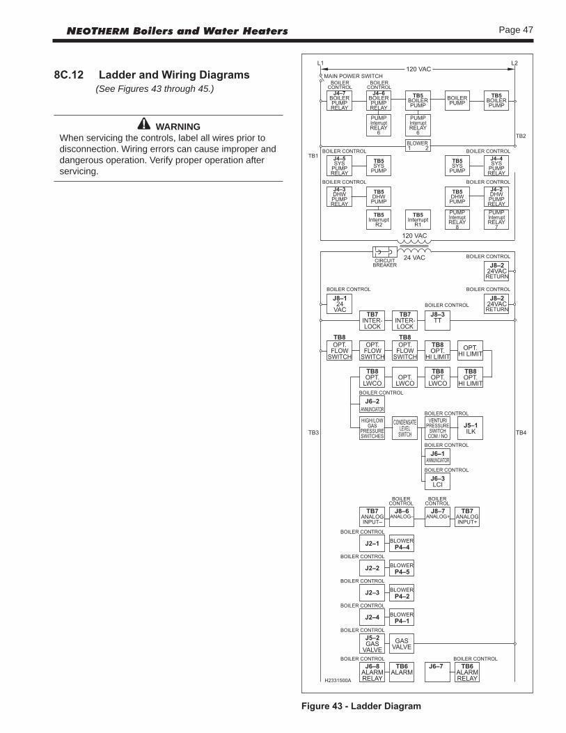
Page 47NEOTHERM Boilers and Water Heaters
8C.12 LadderandWiringDiagrams (See Figures 43 through 45.)
WARNINGWhen servicing the controls, label all wires prior to disconnection. Wiring errors can cause improper and dangerous operation. Verify proper operation after servicing.
Figure43-LadderDiagram

Page 48 LAARS Heating Systems
Figure44-WiringDiagram,AllSizes(withstandardEMEAdisplay)H2354300B
BOIL
ERPU
MP
GN
D
BLK
WH
GN
X01
123
12 1110 9
8 76 5
47
6 54
X07
123
8
PRES
SURE
SWITC
HBR
OR/
WH
BR
OR/WH
NC
CO
M
THER
MO
-FUS
E
(ON
SO
ME
MO
DEL
S)
GY/
WH
MB1
MB2
ECO
MB
AV
DC
BG
ND
THER
MO
-FUS
E
OPT
ION
AL
SWITC
H US
ED O
N S
OM
E M
OD
ELS.
IF S
WITC
H IS
NO
T IN
STA
LLED
IN
THIS
LO
CA
TION
, THE
TE
RMIN
AL
JUM
PER
SHO
ULD
BE
IN P
LAC
E
1
OR
BL
GY/WH
DKB/Y
TO T
B4
J6-8
J6-7
J6-3
SEE
TA
BLE
2
OPT
ION
AL
SWITC
H US
ED O
N S
OM
E M
OD
ELS.
IF S
WITC
H IS
NO
T IN
STA
LLED
IN
THIS
LO
CA
TION
. THE
TE
RMIN
AL
JUM
PER
SHO
ULD
BE
IN P
LAC
E
J8-5
J8-4
J8-3
PUM
PSY
S
DH
W
FAC
TORY
INST
ALL
EDO
PTIO
N F
OR
500
-850
CSD
-1 O
NLY
TABL
E 2.
GA
S VA
LVE
WIR
E C
OLO
RS
TABL
E 1.
CO
LOR
ABB
REVI
ATIO
NS
NO
CO
M
VT
BLK/
Y
GR
BLK
TAN
/R
TN/B
L
TN/B
LK
WH
TN/B
RN
OR
BRN
BRN
PUM
P B
YPA
SSRE
LAY
78
5312 4 6
R2
MS-
1
MS-
2
GY/
WH
SYSTEM SENSOR
AQUASTATOPTION
BLK/OR
DHW TEMP SENSOR
ALARM
WH/OR
WH/GY
OR/BLK
BL/Y
BL
TO J
6-8
TO J
6-7
ALARM
TB6
FIEL
D C
ON
NEC
TION
S
WH & GR
Y
BLK/
OR
OR/
BLK
J10-
8J1
0-7
732
GN
D
GA
SVA
LVE
4123
PRES
SURE
SWITC
H
OR
PUR
OR
PUR
SPA
RKIG
NITO
R
J1-3
J1-2
GY
21
21
61
16
16
61
1 2
21
TO GA
SV
ALV
EP1
WH
WH
DRY
CO
NTA
CTS
ON
LY
FIEL
D
OPT
ION
S
OUTDOOR TEMP SENSOR
LNEU
TRA
LPU
MP
LNEU
TRA
L
GY
CRI
MP
NUT
GR
WH
BLK
TO T
B8 P
1
BLK
GY
DKB
GY
TO T
B4-P
1
TO J
4-10
Y
TO T
B6 P
1TO
TB6
P2
WH
/GY
WH
/OR
TO J
6-2
WH/R/GN
GY/R
GR/VT
R
GR/BL
BL
WH/GY
TN/B
LK
WH
TNTN
/Y
PUR/
BLK
PUR
R/Y
BRN
BRN
/WH
WH
/R
TO T
B2 P
IN2
TO X
FORM
ER
WH
TO T
B1 P
IN2
TO XFO
RMER
BLK
FLO
WSW
ITCH
R
AD
D'L
HIG
HLI
MIT
BL
Y
GR/
BL
GR/
VT
WH
/GY
FIEL
D IN
STA
LLED
OPT
ION
S
LOW
WA
TER
CUT
OFF
GY/
R
BLK
BLK
Y
WH
WH
VT
GY/
BL
YR
WH
BLK
Y
DKB
Y
Y
TN/R
TN/B
L
OR
TN/B
RN
GY/
R
WH/
R/G
N
CL
CL
CL
CL
CL
WH
GR/
RW
H/G
N
R/BLK
PK
DKB/Y
FS-1
LTG
N
R
R/Y
BR/WH
BR
TN/Y
TN
R
Y
WH
/R
WH
/R WH
/BL
WH
/BL
DKB
DKB
FS-2
DKB
DKB
/Y
DKB
WH
/BL
PUR/
BLK
PUR
R
CO
NTR
OL
MO
DULE
(Hon
eyw
ell)
CUS
TOM
ERPO
WER
INPU
T
GR
WH
BLK
TB1
110V
"HO
T"
TB2
110V
NEU
TRA
L
TB3
24V
"HO
T"
TB4
24V
CO
MM
ON
SW 1
J4-6
J4-1
0J4
-12
GN
D
J4-7
TB5
BOIL
ER
CO
NN
ECTIO
NS
J4-5
J4-4
J4-3
J4-2
J5-1
J5-2
SAFE
TYC
HAIN
J8-1
2J8
-11
J8-1
0J8
-9J8
-8J8
-7J8
-6
J8-2
J8-1
J2-1J2-2J2-3J2-4
J9-6
J9-5
J9-4
J9-2
J9-1
TB7
FIEL
DC
ON
NEC
TION
S
OUTDOOR TEMP SENSOR
ANALOG INPUT -ANALOG INPUT +
T-T OR INTERLOCK
OUT
LET
TEM
PSE
NSO
R(P
2)
INLE
TTE
MP
SEN
SOR
(P1)
STA
CK
TEM
P(P
3)
GN
D
21
3
TB8
FIEL
DC
ON
NEC
TION
S
J6-2
J6-1
1 5
1 3
P4P5
HV
SPA
RK
GN
D
TRANSFORMER110VAC INPUT24VAC OUTPUT
BLO
WER
FLA
ME
ROD
CO
NDE
NSA
TELE
VEL
SWITC
HHI
GH/
LOW
GA
S PR
ESSU
RESW
ITCH
500-
850
CSD
-1 O
NLY
12
34
12
34
2
GY
DISP
LAY
(Hon
eyw
ell)
DISP
LAY
(Hon
eyw
ell)
LTG
N
OR/
GN
OR/
GN
GY/
GN
Y
Y
AV
-V
+R1
BLK/
Y
BOIL
ER P
UMP
INTE
RRUP
TJU
MPE
RS
BL =
BLU
E
WH
= W
HITE
Y =
YELL
OW
OF
CO
NN
ECTO
R (IN
SERT
ION
EN
D)
DKB
= D
ARK
BLU
E
CL
- CLE
AR
BRN
= B
ROW
N
GN
= G
REEN
R =
RED
TN =
TA
N
VT
= V
IOLE
T
TABL
E 1
-CO
LOR
ABB
REV
IATIO
NS
BLK
= BL
AC
K
LTG
N =
LIG
HT
GRE
EN
GY
= G
RAY
1.A
LL C
ON
NEC
TORS
ARE
VIE
WED
FRO
M R
EAR
NO
TES:
OR
= O
RAN
GE
PUR
= PU
RPLE
TABL
E 2
- GA
S V
ALV
E W
IRE
CO
LORS
GA
S V
ALV
E PI
N N
O.
80-
285
399
-500
600
-850
YRB
Y1
KBLB
-2
LB-
BKD
3NR
GA
NN
G4
H235
4300
B

Page 49NEOTHERM Boilers and Water Heaters
Figure45-WiringDiagram,AllSizes-withOptionalFull-ColorTouchscreenH2355400B
BOIL
ERPU
MP
GN
D
BLK
WH
GN
COM
2
24Vac24V com
12
34
56
78
TO T
B4-1
TO T
B3-1
COM
1
BL/G
N
Y/G
N
PRES
SURE
SWITC
HBR
OR/
WH
BR
OR/WH
NC
CO
M
MB1
MB2
ECO
MB
AV
DC
BG
ND
THER
MO
-FUS
E
OPT
ION
AL
SWITC
H US
ED O
N S
OM
E M
OD
ELS.
IF S
WITC
H IS
NO
T IN
STA
LLED
IN
THIS
LO
CA
TION
. THE
TE
RMIN
AL
JUM
PER
SHO
ULD
BE
IN P
LAC
E
1
OR
BL
GY/WH
DKB/Y
TO T
B4
J6-8
J6-7
J6-3
SEE
TA
BLE
2
OPT
ION
AL
SWITC
H US
ED O
N S
OM
E M
OD
ELS.
IF S
WITC
H IS
NO
T IN
STA
LLED
IN
THIS
LO
CA
TION
. THE
TE
RMIN
AL
JUM
PER
SHO
ULD
BE
IN P
LAC
E
J8-5
J8-4
J8-3
PUM
PSY
S
DH
W
FAC
TORY
INST
ALL
EDO
PTIO
N F
OR
500
-850
CSD
-1 O
NLY
TABL
E 2.
GA
S VA
LVE
WIR
E C
OLO
RS
TABL
E 1.
CO
LOR
ABB
REVI
ATIO
NS
NO
CO
M
VT
BLK/
Y
GRYBLK
BLK/
Y
TAN
/R
TN/B
L
TN/B
LK
WH
TN/B
RN
OR
BRN
BRN
PUM
P B
YPA
SSRE
LAY
78
5312 4 6
R1 R2
MS-
1
MS-
2
GY/
WH
SYSTEM SENSOR
AQUASTATOPTION
BLK/OR
DHW TEMP SENSOR
ALARM
WH/OR
WH/GY
OR/BLK
BL/Y
BL
TO J
6-8
TO J
6-7
ALARM
TB6
FIEL
D C
ON
NEC
TION
S
WH & GR
Y
BLK/
OR
OR/
BLK
J10-
8J1
0-7
732
GN
D
GA
SVA
LVE
4123
PRES
SURE
SWITC
H
OR
PUR
OR
PUR
SPA
RKIG
NITO
R
J1-3
J1-2
GY
21
21
61
16
16
61
1 2
21
TO GA
SV
ALV
EP1
WH
WH
DRY
CO
NTA
CTS
ON
LY
FIEL
D
OPT
ION
S
OUTDOOR TEMP SENSOR
LNEU
TRA
LPU
MP
LNEU
TRA
L
GY
CRI
MP
NUT
GR
WH
BLK
TO T
B8 P
1
BLK
GY
DKB
GY
TO T
B4-P
1
TO J
4-10
Y
TO T
B6 P
1TO
TB6
P2
WH
/GY
WH
/OR
TO J
6-2
WH/R/GN
GY/R
GR/VT
R
GR/BL
BL
WH/GY
TN/B
LK
WH
TN
TN/Y
PUR/
BLK
PUR
R/Y
BRN
BRN
/WH
WH
/R
TO T
B2 P
IN2
TO X
FORM
ER
WH
TO T
B1 P
IN2
TO XFO
RMER
BLK
FLO
WSW
ITCH
R
AD
D'L
HIG
HLI
MIT
BL
Y
GR/
BL
GR/
VT
WH
/GY
FIEL
D IN
STA
LLED
OPT
ION
S
LOW
WA
TER
CUT
OFF
GY/
R
BLK
BLK
Y
WH
WH
VT
GY/
BL
YR
WH
BLK
Y
DKB
Y
Y
TN/R
TN/B
L
OR
TN/B
RN
GY/
R
WH/
R/G
N
CL
CL
CL
CL
CL
WH
GR/
RW
H/G
N
R/BLK
PK
DKB/Y
FS-1
R
R/Y
BR/WH
BR
TN/Y
TN
R
Y
WH
/R
WH
/R WH
/BL
WH
/BL
DKB
DKB
FS-2
DKB
DKB
/Y
DKB
WH
/BL
PUR/
BLK
PUR
R
CO
NTR
OL
MO
DULE
(Hon
eyw
ell)
CUS
TOM
ERPO
WER
INPU
T
GR
WH
BLK
TB1
110V
"HO
T"
TB2
110V
NEU
TRA
L
TB3
24V
"HO
T"
TB4
24V
CO
MM
ON
SW 1
J4-6
J4-1
0J4
-12
GN
D
J4-7
TB5
BOIL
ER
CO
NN
ECTIO
NS
J4-5
J4-4
J4-3
J4-2
J5-1
J5-2
SAFE
TYC
HAIN
J8-1
2J8
-11
J8-1
0J8
-9J8
-8J8
-7J8
-6
J8-2
J8-1
J2-1J2-2J2-3J2-4
J9-6
J9-5
J9-4
J9-2
J9-1
TB7
FIEL
DC
ON
NEC
TION
S
OUTDOOR TEMP SENSOR
ANALOG INPUT -ANALOG INPUT +
T-T OR INTERLOCK
OUT
LET
TEM
PSE
NSO
R(P
2)
INLE
TTE
MP
SEN
SOR
(P1)
STA
CK
TEM
P(P
3)
GN
D
21
3
TB8
FIEL
DC
ON
NEC
TION
S
J6-2
J6-1
1 5
1 3
P4P5
HV SPA
RK
GN
D
TRANSFORMER110VAC INPUT24VAC OUTPUT
BLO
WER
FLA
ME
ROD
CO
NDE
NSA
TELE
VEL
SWITC
HHI
GH/
LOW
GA
S PR
ESSU
RESW
ITCH
500-
850
CSD
-1 O
NLY
12
34
12
34
2
GY
DISP
LAY
TOUC
H-SC
REEN
LTG
NO
R/G
N
AV
-V
+
GY/
WH TH
ERM
O-F
USE
(ON
SO
ME
MO
DEL
S)
BOIL
ER P
UMP
INTE
RRUP
T JU
MPE
RS
BL =
BLU
E
WH
= W
HITE
Y =
YELL
OW
H235
5400
B
DKB
= D
ARK
BLU
E
CL
- CLE
AR
BRN
= B
ROW
N
R =
RED
1.TN
= T
AN
VT
= V
IOLE
T
TABL
E 1
-CO
LOR
ABB
REV
IATIO
NS
PUR
= PU
RPLE
LTG
N =
LIG
HT
GRE
EN
GY
= G
RAY
GN
= G
REEN
BLK
= BL
AC
K
ALL
CO
NN
ECTO
RS A
RE V
IEW
ED F
ROM
REA
R
NO
TES:
OR
= O
RAN
GE
OF
CO
NN
ECTO
R (IN
SERT
ION
EN
D)
TABL
E 2
- GA
S V
ALV
E W
IRE
CO
LORS
GA
S V
ALV
E PI
N N
O.
80-
285
399
-500
600
-850
YRB
Y1
KBLB
-2
LB-
BKD
3NR
GA
NN
G4
(Kit#KM50D7130)

Page 50 LAARS Heating Systems
ready for operation.
14. Prime the condensate trap with water. (This is not required for NTH 600, 750, and 850 units.)
15. Refer to local codes and the make-up water valve manufacturer’s instructions as to whether the make-up water valve should be left open or closed.
16. After placing the unit in operation, the ignition system safety shutoff device must be tested.
First, shut off the manual gas valve, and call the unit for heat. The main gas terminals will be energized, and attempt to light, for four seconds, and then will de-energize. The unit will go into lockout after the required number of trial for ignition periods.
Next, turn the power Off, and then On again. Press the manual reset button on the boiler control, open the manual gas valve, and allow the unit to light. While the unit is operating, close the manual gas valve and ensure that power to the main gas valve has been cut.
17. Within three days of start-up, recheck all air bleeders and the expansion tank as described in Steps 4 and 8 above.
ImportantNote: The installer is responsible for identifying to the owner/operator the location of all emergency shutoff devices.
WARNINGDo not use this appliance if any part has been under water. Laars Heating Systems requires boilers and water heaters to be replaced, not repaired, if they have been partially or completely submerged.
9.2 FirstOperation
CautionThe initial setup must be checked before the unit is put in operation. Problems such as failure to start, rough ignition, strong exhaust odors, etc. can be due to improper setup. Damage to the boiler resulting from improper setup is not covered by the limited warranty.
REQUIRED TOOLS: differential pressure gauge capable of reading negative 0.01 inches W.C. (0.002kPa), screw drivers, Torx bits, combustion analyzer.
1. Using this manual, make sure the installation is complete and in full compliance with the instructions and all local codes.
2. Determine that the appliance and system are filled with water and all air has been bled from both. Open all valves.
Section 9 - FIRST START-UP AND ADJUSTMENT INSTRUCTIONS
9.1 FillingtheBoilerSystem1. Ensure the system is fully connected. Close all bleeding
devices and open the make-up water valve. Allow the system to fill slowly.
2. If a make-up water pump is employed, adjust the pressure switch on the pumping system to provide a minimum of 12 psi (81.8 kPa) at the highest point in the heating loop.
3. If a water pressure regulator is provided on the make-up water line, adjust the pressure regulator to provide at least 12 psi (81.8 kPa) at the highest point in the heating loop.
4. Open all of the bleeding devices on all radiation units at the high points in the piping throughout the system, unless automatic air bleeders are provided at these points.
Note - There is an air bleed located on the left side of NeoTherm unit, on top of the water manifold.
5. Cycle the boiler pump on and off 10 times, 10 seconds on and 10 seconds off, to remove all air from the heat exchanger. Then run the system and appliance pumps for a minimum of 30 minutes with the gas shut off.
WARNINGFailure to remove all air from the heat exchanger could lead to property damage, severe injury or death.
6. Open all strainers in the circulating system, check the operation of the flow switch (if equipped), and check for debris. If any debris is present, clean it out to ensure proper circulation.
7. Recheck all air bleeders as described in Step 4.
9. Start up the boiler according to the procedure listed in this manual. Operate the entire system, including the pump, boiler, and radiation units for one hour.
11. Shut down the entire system and vent all radiation units and high points in the system piping, as described in Step 4.
12. Close the make-up water valve and check the strainer in the pressure reducing valve for sediment or debris from the make-up water line. Reopen the make-up water valve.
13. Check the gauge for correct water pressure and also check the water level in the system. If the height indicated above the boiler insures that water is at the highest point in the circulating loop, then the system is

Page 51NEOTHERM Boilers and Water Heaters
3. Observe all warnings on the Operating Instructions label and turn on the gas and electrical power to the appliance.
4. The NeoTherm unit will begin the start sequence. The blower and pump will energize for the pre-purge period, then the ignition sequence will start. After all safety devices have been verified, the gas valve will open. If ignition doesn’t occur, turn off the NeoTherm, and check that there is proper gas supply. Wait 5 minutes before restarting.
5. Turn the NeoTherm on.6. After placing the appliance in operation, the Burner
Safety Shutoff Device must be tested: • Close the gas shutoff valve with the burner operating. • The flame will go out and the blower will
continue to run for the post purge cycle. One or three additional attempts to light will follow. Each cycle will include pre-purge, ignitor on, valve/flame on, and post purge. Ignition will not occur because the gas is off. The ignition control will lockout.
• Open the gas shutoff valve. Reset the boiler control by pressing the Reset button on the control or on the display. Restart the appliance. The ignition sequence will start again and the burner will start. The appliance will return to its previous mode of operation.
DANGERIf you detect any odor of gas, or if the gas burner does not appear to be functioning in a normal manner, CLOSE THE MAIN SHUTOFF VALVE. Do not shut off the switch. Contact your heating contractor, gas company, or factory representative.
9.3AdjustingCO21. Measure the CO2/O2 in the flue products at high fire.
The NeoTherm can be forced to high fire to allow for easier setup. The controller has a feature that makes it easy to go directly to the high fire condition. The unit will operate at high fire for 5 minutes, then modulate down automatically. How to get there: From the “Home” screen, press “I” to go to “Info/ Install.” Choose “Test,” then go to “Forced Rate.” Select “Set High Fire,” then select “Start Test.” The CO2 readings should be between the values shown in Table 15 R or Table 15 C. If the CO2 is not within the range shown, adjustments may be made. To adjust the high fire CO2, locate the high fire adjuster screw according to the appropriate figure. Slowly make adjustments in 1/16 of a revolution increments until the CO2 is within the range identified.
2. Measure the CO2/O2 in the flue products at low fire.
3. Repeat steps 1 and 2 to confirm that the CO2 ranges are within the required ranges. Adjust if necessary.
4. Confirm that the differential pressure is still within the appropriate range.
5. If any of the measurements cannot be adjusted to the specified ranges or the CO levels are above 150ppm when adjusted, please consult the factory for further information.
WARNINGImproper adjustment may lead to poor combustion quality, increasing the amount of carbon monoxide produced. Excessive carbon monoxide levels may lead to personal injury or death.
Table15C(Commercial,sizes399-850Mbtu)CO2RangeandManifoldPressure
GAS TYPE HIGH FIRE, CO2 LOW FIRE, CO2 DIFFRNTL PRESSURE (incheswc)
Natural 8.8 to 9.8% 0.5% lower than 3.6” to 3.9”
Propane 9.8 to 10.2% high fire setting
Table15R(Residential,sizes80-285Mbtu) CO2RangeandDifferentialPressure
NeoTherm can be forced to low fire to allow for easier setup.
How to get there: From the “Home” screen, press “I” to go to “Info/ Install.” Choose “Test,” then go to “Forced Rate.” Select “Set High Fire,” then select “Start Test.”
The CO2 readings should be between the values shown in Tables 15 R or Table 15 C. If the CO2 is not within the range shown, adjustments may be made. To adjust the low fire CO2, locate the low fire adjuster screw according to the appropriate figure. Slowly make adjustments in 1/16 of a revolution increments until the CO2 is within the range identified.
GAS TYPE HIGH FIRE, CO2 LOW FIRE, CO2 MANIFOLD PRESSURE
Natural 8.8 to 9.0% 0.5% lower than -.005” to
Propane 9.8 to 10.0% high fire setting -.015” wc
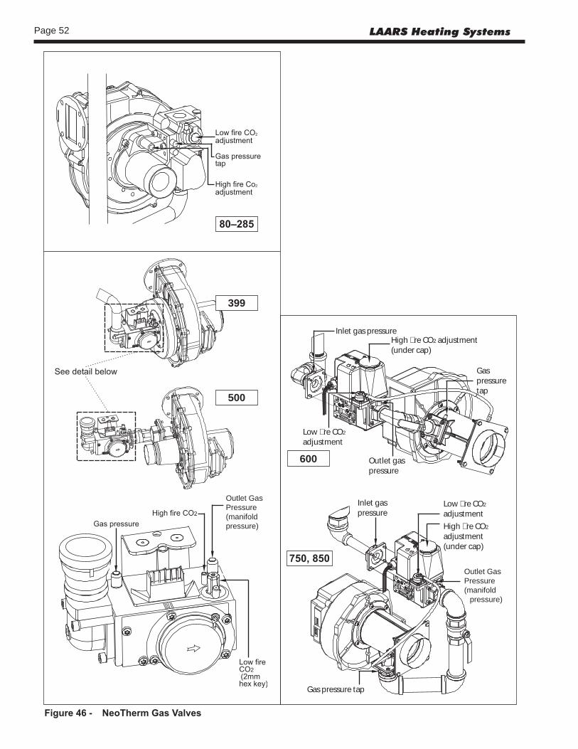
Page 52 LAARS Heating Systems
600
750,850
Figure46- NeoThermGasValves
80–285
500
399
Inlet gas pressureHigh �re CO2 adjustment(under cap)
Gas pressuretap
Low �re CO2
adjustment
Outlet gaspressure
Inlet gaspressure
Low �re CO2
adjustmentHigh �re CO2
adjustment(under cap)
Outletgas pressure
Gas pressure tap
Outlet Gas Pressure (manifold pressure)
Outlet Gas Pressure (manifold
pressure)
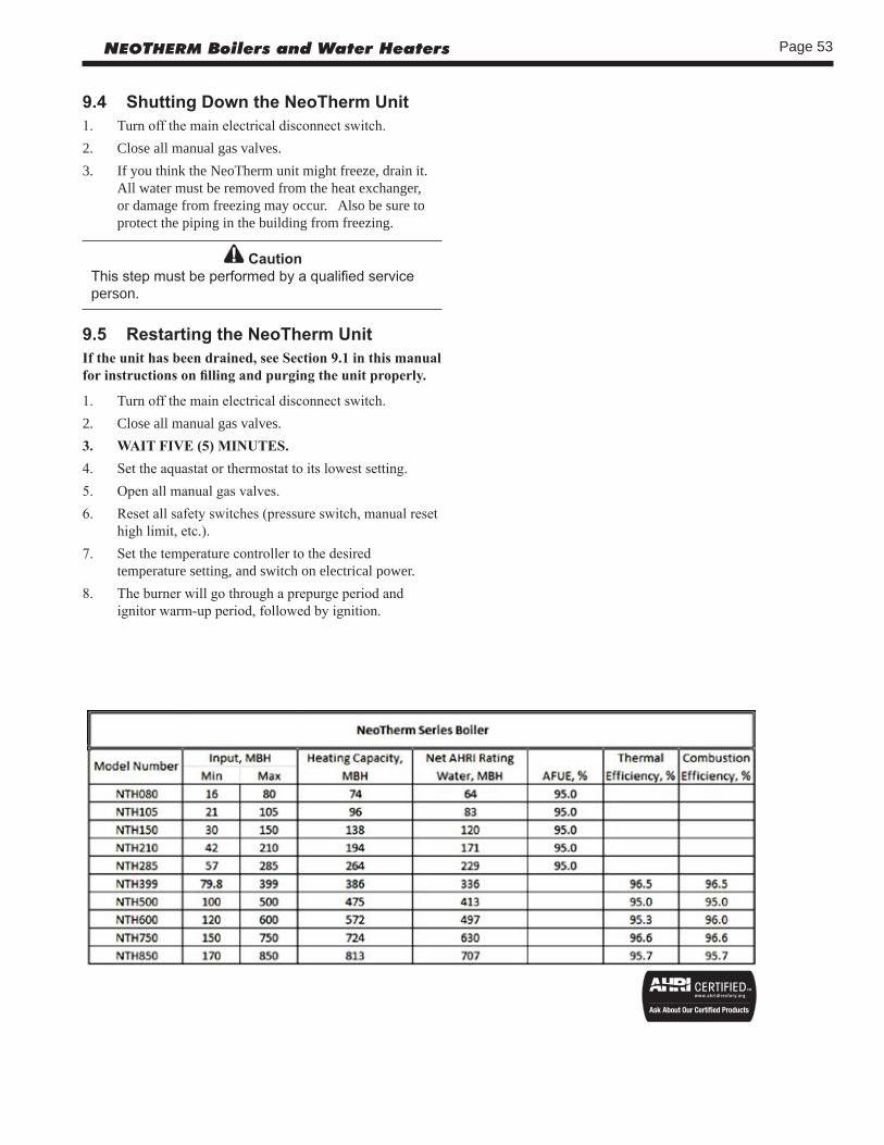
Page 53NEOTHERM Boilers and Water Heaters
9.4 ShuttingDowntheNeoThermUnit1. Turn off the main electrical disconnect switch.2. Close all manual gas valves.3. If you think the NeoTherm unit might freeze, drain it.
All water must be removed from the heat exchanger, or damage from freezing may occur. Also be sure to protect the piping in the building from freezing.
CautionThis step must be performed by a qualified service person.
9.5 RestartingtheNeoThermUnitIf the unit has been drained, see Section 9.1 in this manual for instructions on filling and purging the unit properly.
1. Turn off the main electrical disconnect switch.2. Close all manual gas valves.3. WAIT FIVE (5) MINUTES.4. Set the aquastat or thermostat to its lowest setting.5. Open all manual gas valves.6. Reset all safety switches (pressure switch, manual reset
high limit, etc.).7. Set the temperature controller to the desired
temperature setting, and switch on electrical power.8. The burner will go through a prepurge period and
ignitor warm-up period, followed by ignition.

Page 54 LAARS Heating Systems
Section 10MAINTENANCE
WARNINGDisconnect all power to the appliance before attempting any service. Contact with electricity can result in severe injury or death.
10.1SystemMaintenance Do this once a year, unless otherwise noted.1. Lubricate the system water-circulating pump, if
required, per the instructions on the pump. 2. If a strainer is employed in a pressure reducing valve or
the piping, clean it every six months.3. Inspect the venting system for obstruction or leakage at
least once a year. Periodically clean the screens in the vent terminal and combustion air terminal (when used).
4. Keep the area around the appliance clear and free of combustible materials, gasoline, and other flammable vapors and liquids.
5. If the appliance is not going to be used for extended periods in locations where freezing normally occurs, it should be isolated from the system and completely drained of all water.
6. Low water cutoffs, if installed, should be checked every year. Float-type low water cutoffs should be flushed periodically.
7. Inspect and clean the condensate collection, float switch and disposal system yearly.
8. When a means is provided to neutralize the condensate, ensure that the condensate is being neutralized properly.
9. Inspect the flue passages, and clean with a brush or vacuum if necessary. Sooting in flue passages indicates improper combustion. Determine the cause for this and correct it.
10. Inspect the vent system and air intake system, and ensure that all joints are sealed properly. If any joints need to be resealed, completely remove any existing sealing material, and clean the joint(s) with alcohol. Apply new sealing material, and reassemble.
10.2ApplianceMaintenanceandComponent Description
Use only genuine LAARS replacement parts.
CautionLabel all wires prior to disconnection when servicing controls. Wiring errors can cause improper and danger-ous operation. Verify proper operation after servicing.
The gas and electric controls in the unit are engineered for long life and dependable operation, but the safety of equipment depends on their proper functioning. Only a
qualified service technician should inspect the basic items listed below every year: a. Appliance control f. Flow switch b. Automatic gas valve g. Low water cutoff c. Pressure switches h. Burner d. Blower i. Heat exchanger e. Pump
BurnerCheck the burner for debris. Remove the blower arm assembly to access the burner. Remove the four bolts connecting the blower to the arm. (See Figure 47.) Remove the five bolts which hold the burner arm in place. Pull the burner up and out. Clean the burner, if necessary, by blowing compressed air from the outside of the burner into the center, and wipe the inside clean with glass cleaner. A dirty burner may be an indication of improper combustion or dirty combustion air. Determine the cause of this, and correct it. If the burner gasket is damaged, replace it when replacing the burner.
NOTE: When installing the burner, make sure the flange is aligned with the mating surface, as each is keyed to control the fit.
ModulatingGasValve/VenturiThe modulating gas valve consists of a valve body that incorporates the On/Off gas flow control and a negative pressure regulator. It provides the air/gas ratio control in combination with the Venturi to the unit. It is designed to operate with a gas supply pressure between 4 and 13 inches w.c. To remove the gas valve and/or Venturi, shut off the 120 Volt power supply to the boiler. Turn off all manual gas valves connecting the boiler to the main gas supply line. Remove the front door of the boiler to gain access to the gas valve and Venturi. Disconnect the four flange bolts connecting the gas manifold pipe to the gas valve. Remove the electrical connections to the gas valve. Remove the bolts connecting the Venturi flange to the blower. This allows the entire gas valve and Venturi assembly to be removed to facilitate inspection and cleaning. Reassemble the valve/Venturi assembly in reverse order, making sure to include all gaskets and O-rings. Turn on the manual gas valves and check for gas leaks. Turn on the 120 Volt power. Place the unit in operation following the instructions in Section 9. Once the boiler is operating. check for leaks again and confirm that all fasteners are tight.Check the appliance setup according to Section 9.
ApplianceControlThe NeoTherm unit has an integrated control that incorporates manual reset high limit control, operating temperature control, modulating control, ignition control, outdoor reset control, pump control and many other features. If any of these features are thought to be defective, please consult the factory for proper trouble shooting practices prior to replacing

Page 55NEOTHERM Boilers and Water Heaters
the control. If control replacement is required, turn off all power to the appliance and shut off all manual gas valves to the appliance. Remove the front door to the appliance and the plastic bezel and the control panel. Remove all wire connections from the control board. The control board connections are keyed to only allow connection in the proper location, but proper handling techniques should be used to avoid damage to the wiring or connectors. To remove the control, push in on the two tabs on the left side of the board to unlatch the clips from the control panel. Rotate the control around the fastening points on the right side of the control to remove the hooks from the control panel. To replace the control, repeat the steps listed above in the reverse orders making sure to connect all wires in the proper locations. Place the appliance in operation following the steps outlined in Section 9.
IgnitorAssemblyThe ignitor assembly is a two rod system that consists of a ground rod and a spark rod (See Figure 47). To remove the ignitor assembly, shut off the 120 Volt power supply to the appliance. Turn off all manual gas valves connecting the appliance to the main gas supply line. Remove the front door of the boiler to gain access to the ignitor assembly. Remove the two wires connected to the assembly. Then remove the
two bolts connecting the ignitor assembly to the burner door. If the old ignitor assembly is determined to be defective, install a new ignitor assembly (check that the spark gap is 3/16”). Replace the gasket if necessary.
FlameSensorThe flame sensor is a single rod system. To replace the flame sensor electrode, shut off the 120 Volt power supply to the boiler. Turn off all manual gas valves connecting the boiler to the main gas supply line. Remove the front door of the boiler to gain access to the flame sensor electrode. Remove the flame sensor wire from the electrode. Remove the two bolts fastening the electrode to the burner doors. Remove and replace the old flame sensor gasket. If the old electrode is determined to be defective, install a new flame sensor electrode in the reverse order.
CautionThe ignitor and sensor may be hot, and can cause burns or injury.
Figure 47 - Burner Service
NOTES: SPARK IGNITOR1.GIANNONI #gm10-35-108-01
1.08
.18
W20131
3.1
3/16”
IgnitorAssembly
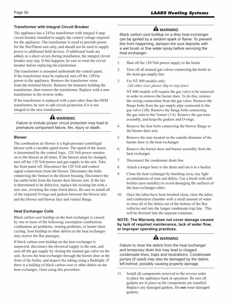
Page 56 LAARS Heating Systems
TransformerwithIntegralCircuitBreakerThe appliance has a 24Vac transformer with integral 4 amp circuit breaker installed to supply the control voltage required for the appliance. The transformer is sized to provide power for the NeoTherm unit only, and should not be used to supply power to additional field devices. If additional loads are added, or a short occurs during installation, the integral circuit breaker may trip. If this happens, be sure to reset the circuit breaker before replacing the transformer.The transformer is mounted underneath the control panel. If the transformer must be replaced, turn off the 120Vac power to the appliance. Remove the transformer wires from the terminal blocks. Remove the fasteners holding the transformer, then remove the transformer. Replace with a new transformer in the reverse order.If the transformer is replaced with a part other than the OEM transformer, be sure to add circuit protection if it is not integral to the new transformer.
WARNINGFailure to include proper circuit protection may lead to premature component failure, fire, injury or death.
BlowerThe combustion air blower is a high-pressure centrifugal blower with a variable speed motor. The speed of the motor is determined by the control logic. 120 Volt power remains on to the blower at all times. If the blower must be changed, turn off the 120 Volt power and gas supply to the unit. Take the front panel off. Disconnect the 120 Volt and control signal connections from the blower. Disconnect the bolts connecting the Venturi to the blower housing. Disconnect the fan outlet bolts from the burner door blower arm. If the fan is determined to be defective, replace the existing fan with a new one, reversing the steps listed above. Be sure to install all of the required O-rings and gaskets between the blower arm and the blower and blower face and venturi flange.
HeatExchangerCoilsBlack carbon soot buildup on the heat exchanger is caused by one or more of the following; incomplete combustion, combustion air problems, venting problems, or heater short cycling. Soot buildup or other debris on the heat exchanger may restrict the flue passages.If black carbon soot buildup on the heat exchanger is suspected, disconnect the electrical supply to the unit, and turn off the gas supply by closing the manual gas valve on the unit. Access the heat exchanger through the burner door at the front of the boiler, and inspect the tubing using a flashlight. If there is a buildup of black carbon soot or other debris on the heat exchanger, clean using this procedure:
WARNINGBlack carbon soot buildup on a dirty heat exchanger can be ignited by a random spark or flame. To prevent this from happening, dampen the soot deposits with a wet brush or fine water spray before servicing the heat exchanger.
1. Shut off the 120 Volt power supply to the boiler
2. Turn off all manual gas valves connecting the boiler to the main gas supply line.
3. For NT 600 models only: (All other sizes please skip to step four) NT 600 models will require the gas valve to be removed
in order to remove the burner door. To do this, remove the wiring connections from the gas valve. Remove the flange bolts from the gas supply pipe connected to the gas valve (1B). Remove the flange bolts connecting the gas train to the Venturi (1A). Remove the gas train assembly, and keep the gaskets and O-rings.
4. Remove the four bolts connecting the blower flange to the burner door arm.
5. Remove the nuts located on the outside diameter of the burner door to the heat exchanger.
6. Remove the burner door and burner assembly from the heat exchanger.
7. Disconnect the condensate drain line.
8. Attach a longer hose to the drain and run it to a bucket.
9. Clean the heat exchanger by brushing away any light accumulations of soot and debris. Use a brush with soft bristles (non metallic) to avoid damaging the surfaces of the heat exchanger tubes.
10. Once the tubes have been brushed clean, rinse the tubes and combustion chamber with a small amount of water to rinse all of the debris out of the bottom of the flue collector and into the longer condensate trap line. This will be diverted into the separate container.
NOTE:TheWarrantydoesnotcoverdamagecausedbylackofrequiredmaintenance,lackofwaterflow,orimproperoperatingpractices.
WARNING
Failure to rinse the debris from the heat exchanger and temporary drain line may lead to clogged condensate lines, traps and neutralizers. Condensate pumps (if used) may also be damaged by the debris left behind, possibly causing property damage.
11. Install all components removed in the reverse order to place the appliance back in operation. Be sure all gaskets are in place as the components are installed. Replace any damaged gaskets. Do not reuse damaged gaskets.
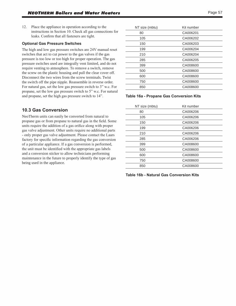
Page 57NEOTHERM Boilers and Water Heaters
NT size (mbtu) Kit number80 CA006201105 CA006202150 CA006203199 CA006204210 CA006204285 CA006205399 CA008600500 CA008600600 CA008600750 CA008600850 CA008600
Table16a-PropaneGasConversionKits
NT size (mbtu) Kit number80 CA006206105 CA006206150 CA006206199 CA006206210 CA006206285 CA006206399 CA008600500 CA008600600 CA008600750 CA008600850 CA008600
Table16b-NaturalGasConversionKits
12. Place the appliance in operation according to the instructions in Section 10. Check all gas connections for leaks. Confirm that all fasteners are tight.
OptionalGasPressureSwitchesThe high and low gas pressure switches are 24V manual reset switches that act to cut power to the gas valves if the gas pressure is too low or too high for proper operation. The gas pressure switches used are integrally vent limited, and do not require venting to atmosphere. To remove a switch, remove the screw on the plastic housing and pull the clear cover off. Disconnect the two wires from the screw terminals. Twist the switch off the pipe nipple. Reassemble in reverse order. For natural gas, set the low gas pressure switch to 3” w.c. For propane, set the low gas pressure switch to 5” w.c. For natural and propane, set the high gas pressure switch to 14”.
10.3GasConversionNeoTherm units can easily be converted from natural to propane gas or from propane to natural gas in the field. Some units require the addition of a gas orifice along with proper gas valve adjustment. Other units require no additional parts - only proper gas valve adjustment. Please contact the Laars factory for specific information regarding the gas conversion of a particular appliance. If a gas conversion is performed, the unit must be identified with the appropriate gas labels and a conversion sticker to allow technicians performing maintenance in the future to properly identify the type of gas being used in the appliance.

Page 58 LAARS Heating Systems
Section 11 -OPERATING DETAILS AND TROUBLESHOOTING
11.1 NormalStartupandInitializationWhen power to the unit is turned on, the controller will automatically go through a startup and initialization procedure. At first the interface will display some information about the control software. See Fig. 48.
Fig.48–FirstInitializationDisplay
Next, the interface will search for the SOLA controller that will actually control the boiler. See Fig. 49.
Fig.49–SecondInitializationDisplay
Once the interface makes the connection to the controller, it will display the address it is using to communicate (the “Modbus address”). The interface will download a series of values from the SOLA controller (or “synchronize” with the controller).When the synchronization is finished, the display will change to the Home screen shown in Fig. 27.
11.2 SequenceofOperationThe NeoTherm is a cold-start appliance. It should start only when it receives a call for heat from a tank aquastat, room thermostat, zone valve end switch or other space temperature control device. 1. The unit receives a call for heat.2. The controller checks the safety chain.3. The fan starts and waits to achieve prepurge RPM.4. The prepurge timer is started once the prepurge RPM is
achieved.
5. There is a pre-ignition time of two seconds to check the flame sensor operation and status. During this period an intermittent spark can be seen.
6. Next there is a trial for ignition period of four seconds. The direct spark ignition switches to constant spark for three seconds. During this time the gas valve is open. For the last second of the ignition period, direct spark is de-energized and the flame sensor checks for established flame. If flame is sensed, the control enters Run to satisfy the demand. If flame is not established, the control enters a retry, starting from step 2. If flame has not been established after the preset number of retries, the control will lockout with a 109 error code.
7. The call for heat signal is removed.8. The gas valve shuts off.9. The fan and pump continue to run for the over-run
times to purge the system.
This is the basic operating sequence of the appliance for a DHW or hydronic call for heat.
11.3 ModulationControlThe control uses a PID algorithm to adjust the firing rate of the boiler as the control point is approached. The goal of the control is to operate at a minimum firing rate to match the load on the appliance. This is done by using a setpoint, and on/ off differentials. The control modulates to achieve the setpoint temperature, which could be several degrees away from the actual off point. The off point is calculated by adding the setpoint plus the off differential. The setpoint and differentials used in operation are dependent upon the type of call for heat being applied. If there is a DHW call, the DHW setpoint and off differentials are used. If there is a hydronic call, the CH setpoint and off differentials are used. When the setpoint plus the off differential is reached, the control prevents the unit from firing until the water temperature reaches the setpoint minus the on differential.
11.4 Pump ControlThe control can operate three pumps. The boiler pump is active any time there is a call for heat applied to the control. The DHW and system pumps are active based upon the call and priority of the heat demand being supplied. When there is a hydronic call supplied, the system pump is active. If there is a DHW call supplied while the hydronic call is active, with DHW priority enabled, the system pump turns off and the DHW pump turns on. Domestic hot water priority forces the control to attempt to satisfy the domestic water demand before the hydronic demand. Once the last heat demand has been satisfied, the boiler pump enters an overrun time.

Page 59NEOTHERM Boilers and Water Heaters
11.5 Anti-Short-Cycle(ASC)Because the NeoTherm unit is a modulating boiler, and its input will decrease when there is a reduction in the heating load, short cycling is greatly reduced. If the heating load drops below the minimum input of the boiler for an extended period, the boiler will have a tendency to short cycle. This can be a symptom of improper control strategy or setpoints, or a load distribution problem. The controller in the NeoTherm unit includes an anti-short cycle (ASC) function. The timer for the ASC can be set to delay the boiler start for a specified time after a call for heat is completed.
11.6 TemperatureSensors
High Limit Sensor -The control uses a dual thermistor sensor to monitor the Neotherm’s maximum temperature. The high limit sensor is installed in the outlet water. A dual thermistor sensor is used, so that the two temperatures can be monitored and compared to confirm accuracy. The control will automatically reduce the firing of the NeoTherm to prevent the high limit from tripping. The high limit setpoint is factory set at 195°. However, if desired you can set a lower limit using the Adjustable High Limit function available from the Quick Start menu.
Outlet Water Temperature -The outlet water temperature is sensed by a dual thermistor sensor, and is limit-rated. The control compares the two temperature readings to determine accuracy. The outlet sensor is used as the primary control point for high limit, temperature operation, and modulation.
Inlet Water Temperature -The inlet water temperature uses a single thermistor sensor. The heat exchanger temperature rise (delta T) is calculated using the inputs from the outlet and inlet sensor temperatures.
Stack Limit -The stack temperature is sensed by a dual thermistor sensor, and is limit-rated. The control compares both of the temperature readings to determine accuracy. The stack sensor is used as a limiting feature to avoid excessive temperatures in the vent.
11.7 DiagnosticsUse the Diagnostics to check the status of the sensors and the digital inputs and outputs. The system also records a history of lockouts and alarms.
Analog Sensors -You can use this display to check on operating temperatures, fan speed, firing rate, etc. (The word “analog” refers to values that can change continuously between zero and a higher value.) The values shown here are “Read Only” – you can’t change them from this display.
Digital Input/Output -This display shows whether different functions, inputs and outputs are either on or off. The functions listed here include pumps, valves, alarms, etc. The values shown here are “Read Only” – you can’t change them from this display.
History -The system records the most recent lockouts or alerts. (If there is a current lockout or alert, a note about this will also appear at the bottom of the Home screen.)• A “lockout” is a condition that will prevent the unit from
starting or running.• An “alert” indicates a condition that is not normal. If it
continues, the control system might move to a “lockout,” or the problem might be corrected.
11.8 Error Codes See Appendix B.

Page 60 LAARS Heating Systems
12.2PartsList
SIZE
SI
ZE
SIZE
SI
ZE
SIZE
SI
ZE
SIZE
SI
ZE
SIZE
SI
ZEIT
EM D
ESC
RIP
TIO
N
NTH
80
NTH
105
N
TH 1
50
NTH
210
N
TH 2
85
NTH
399
N
TH 5
00
NTH
600
N
TH 7
50
NTH
850
NTV
150
N
TV 1
99
NTV
285
N
TV 3
99
NTV
500
N
TV 6
00
NTV
750
N
TV 8
50
JacketCom
ponents–
See
Figu
re 6
3
1 Fr
ont P
anel
Ass
embl
y R
60D
3200
R
60D
3200
R
60D
3200
R
60D
3200
R
60D
3200
R
60D
3201
R
60D
3202
R
60D
3202
R
60D
3202
R
60D
3202
2 Fr
ont P
anel
Han
dle
R50
D32
04
R50
D32
04
R50
D32
04
R50
D32
04
R50
D32
04
R50
D32
04
R50
D32
04
R50
D32
04
R50
D32
04
R50
D32
043
Rea
r Pan
el
R50
D31
01
R50
D31
01
R50
D31
01
R50
D31
01
R50
D31
01
R50
D31
01
R50
D31
01
R50
D31
01
R50
D31
01
R50
D31
014
Left
Sid
e P
anel
R
8D30
02
R10
D30
02
R15
D30
02
R19
D30
02/
R30
D30
02
R40
D30
02
R50
D30
02
R50
D30
02
75D
3002
85
D30
02
R20
D30
025
Rig
ht S
ide
Pan
el
R15
D30
01
R15
D30
01
R15
D30
01
R30
D30
01
R30
D30
01
R40
D30
01
R50
D30
01
R50
D30
01
75D
3001
85
D30
016
Left
Top
Pan
el
8D33
27
10D
3327
R
15D
3303
R
20D
3303
30
D33
12
R40
D33
03
50D
3308
60
D33
03
75D
3303
85
D33
037
Mid
dle
Left
Top
Pan
el
8D33
28
10D
3328
15
D34
02
20D
3403
30
D33
11
40D
3401
50
D34
01
60D
3302
75
D33
02
85D
3302
7A
Mid
dle
Rig
ht T
op P
anel
8D
3329
10
D33
29
15D
3403
20
D34
02
30D
3313
—
—
—
—
—
8 R
ight
Top
Pan
el
8D33
30
10D
3330
15
D34
01
R20
D33
01
30D
3314
40
D34
02
50D
3402
60
D33
01
75D
3301
85
D33
019
Jack
et A
ngle
Sup
port
R8D
3102
R
8D31
02
R15
D31
02
R30
D31
02
R30
D31
02
R40
D31
02
R50
D31
02
R50
D31
02
75D
3102
85
D31
02
(R
ight
Han
d)
(Rig
ht H
and)
(2
) (2
) (2
) (2
) (2
) NTH
(2
) (2
) (2
)
R
15D
3102
R
15D
3102
R
51D
3102
(Lef
t Han
d)
(Lef
t Han
d)
(2) N
TV
10
Jack
et S
uppo
rt,
R50
D30
03
R50
D30
03
R50
D30
03
R50
D30
03
R50
D30
03
R50
D30
03
R50
D30
03
R50
D30
03
R50
D30
03
R50
D30
03
Left
Sta
nchi
on
11
Jack
et S
uppo
rt,
R50
D30
04
R50
D30
04
R50
D30
04
R50
D30
04
R50
D30
04
R50
D30
04
R50
D30
04
R50
D30
04
R50
D30
04
R50
D30
04
Rig
ht S
tanc
hion
12
Fron
t Bez
el
R50
D71
21
R50
D71
21
R50
D71
21
R50
D71
21
R50
D71
21
R50
D71
21
R50
D71
21
R50
D71
21
R50
D71
21
R50
D71
2113
D
ispl
ay m
ount
ing
fram
e R
50D
7122
R
50D
7122
R
50D
7122
R
50D
7122
R
50D
7122
R
50D
7122
R
50D
7122
R
50D
7122
R
50D
7122
R
50D
7122
(12&
13)
Com
plet
e As
sem
bly
R50
D71
20
R50
D71
20
R50
D71
20
R50
D71
20
R50
D71
20
R50
D71
20
R50
D71
20
R50
D71
20
R50
D71
20
R50
D71
20
InternalCom
ponents–
See
Figu
re 6
4
20
Bas
e A
ssem
bly
R15
D11
00
R15
D11
00
R15
D11
00
R30
D11
00
R30
D11
00
R40
D11
00
R50
D11
00
60D
1100
75
D11
00
85D
1100
21
Left
Rea
r Sup
port
R
50D
1001
R
50D
1001
R
50D
1001
R
50D
1001
R
50D
1001
R
50D
1001
R
50D
1001
R
50D
1001
R
50D
1001
R
50D
1001
S
tanc
hion
22
Left
Fron
t/Rig
ht R
ear
R50
D10
02
R50
D10
02
R50
D10
02
—
R50
D10
02
R50
D10
02
R50
D10
02
R50
D10
02
R50
D10
02
R50
D10
02
Sup
port
Sta
nchi
on
(2)
(2)
(2)
(2)
(2)
(2)
Sect
ion
12 -
REP
LAC
EMEN
T PA
RTS
Use
onl
y ge
nuin
e LA
AR
S re
plac
emen
t par
ts.
12.1GeneralInform
ation
To o
rder
or p
urch
ase
parts
for t
he L
AA
RS
Neo
Ther
m, c
onta
ct y
our n
eare
st L
AA
RS
deal
er o
r dis
tribu
tor.
If th
ey c
anno
t sup
ply
you
with
wha
t you
nee
d, c
onta
ct C
usto
mer
Se
rvic
e. (S
ee th
e ba
ck c
over
for t
he a
ddre
ss, t
elep
hone
and
fax
num
bers
.)

Page 61NEOTHERM Boilers and Water Heaters
SIZE
SI
ZE
SIZE
SI
ZE
SIZE
SI
ZE
SIZE
SI
ZE
SIZE
SI
ZEIT
EM D
ESC
RIP
TIO
N
NTH
80
NTH
105
N
TH 1
50
NTH
210
N
TH 2
85
NTH
399
N
TH 5
00
NTH
600
N
TH 7
50
NTH
850
NTV
150
N
TV 1
99
NTV
285
N
TV 3
99
NTV
500
N
TV 6
00
NTV
750
N
TV 8
50
23
Can
tilev
ered
Bas
e
R15
D10
02
R15
D10
02
R15
D10
02
R40
D10
01
R40
D10
01
R40
D10
01
R40
D10
01
R50
D10
03
75D
1002
75
D10
02
Sta
nchi
on
24
Bra
ce, F
ront
, 20
D10
05
20D
1005
20
D10
05
20D
1005
85
D10
05
85D
1005
85
D10
05
60D
1005
85
D10
05
85D
1005
H
X S
tanc
hion
24A
Bra
ce, R
ear,
R
50D
1005
R
50D
1005
20
D10
07
20D
1007
R
50D
1005
85
D10
05
85D
1005
85
D10
05
85D
1005
85
D10
05
HX
Sta
nchi
on
25
Mou
ntin
g R
ail
R15
D10
04
R15
D10
04
R15
D10
04
R30
D10
04
R30
D10
04
40D
1004
R
50D
1004
R
50D
1004
75
D10
04
85D
1004
(2
) (2
) (2
) (2
) (2
) (2
) (2
)
26A
Dia
gona
l Bra
ce
—
—
—
—
—
—
—
—
75D
1006
75
D10
06
(2
) (2
)
27
Con
dens
ate
Trap
Ass
y R
20D
4020
R
20D
4020
R
20D
4020
R
20D
4020
R
50D
4020
R
50D
4020
R
50D
4020
A
2116
300
A21
1630
0 A
2116
300
28
Hea
t Exc
h. R
ail C
lip
R50
D10
06
R50
D10
06
—
—
R50
D10
06
—
—
—
—
—
(2
) (2
)
(2
)
30
PV
C R
educ
er
—
—
RP
2053
000
RP
2053
000
RP
2052
900
RP
2052
800
50D
4027
R
P20
5280
0 R
P20
5280
0 R
P20
5280
030
a C
PV
C R
educ
er
RD
2010
501
RD
2010
501
RP
2065
600
RP
2065
600
—
—
—
—
R75
D40
20
R75
D40
20
or C
oupl
ing
30b
2” D
ia. P
ipe,
CP
VC
R
D20
1021
2 R
D20
1021
2 R
D20
1021
3 R
D20
1021
3 —
—
—
—
—
—
N
TV
R
D20
1021
3
NTH
31
Hos
e B
arbe
d A
dapt
er
RP
2067
100
RP
2067
100
RP
2056
100
RP
2056
100
RP
2056
100
—
—
—
—
—33
A
ir In
let/E
xhau
st B
rack
et R
8D30
05
10D
3005
R
20D
3120
R
20D
3120
30
D35
05
40D
3005
85
D30
05
85D
3005
85
D30
05
85D
3005
GasTrainCom
ponents–
See
Figu
re 6
5 40
C
ombu
stio
n A
ir B
low
er
RA
2113
700
RA
2113
700
RA
2107
500
RA
2114
200
RA
2114
200
RA
2113
100
RA
2113
100
R20
1210
1 R
2012
101
R20
1210
141
G
as V
alve
/Ven
turi
RV
2017
900
RV
2017
901
RV
2017
902
RV
2017
903
RV
2017
904
—
—
—
—
—42
G
as V
alve
—
—
—
—
—
R
V20
1920
0 V
2019
600
V20
1850
0 V
2018
500
V20
1850
043
G
as/A
ir Ve
ntur
i —
—
—
—
—
—
R
A21
1670
0 A
2115
000
A21
1500
0 A
2115
000
44
Man
ual G
as V
alve
—
—
—
—
—
R
V20
0020
0 V
2003
000
V20
0300
0 V
2003
200
V20
0320
0
(2)
44A
Man
ual G
as V
alve
—
—
—
—
—
—
R
V20
0020
0 —
V
2003
000
V20
0300
045
G
as V
alve
Fla
nge
Kit
—
—
—
—
—
—
RP
2050
100
RP
2050
100
RP
2050
100
RP
2050
100
46
Gas
Val
ve/V
entu
ri
—
—
—
—
—
—
RS
2104
900
RS
2104
900
RS
2104
900
RS
2104
900
C
ork
Gas
ket
47
Gas
Val
ve O
-Rin
g R
30-2
27
R30
-227
R
30-2
27
R30
-227
R
30-2
27
—
—
—
—
—48
Ve
ntur
i O-R
ing
—
—
—
—
—
RS
2105
200
RS
2105
200
RS
2105
200
RS
2105
200
RS
2105
200

Page 62 LAARS Heating Systems
SI
ZE
SIZE
SI
ZE
SIZE
SI
ZE
SIZE
SI
ZE
SIZE
SI
ZE
SIZE
ITEM
DES
CR
IPTI
ON
N
TH 8
0 N
TH 1
05
NTH
150
N
TH 2
10
NTH
285
N
TH 3
99
NTH
500
N
TH 6
00
NTH
750
N
TH 8
50
N
TV 1
50
NTV
199
N
TV 2
85
NTV
399
N
TV 5
00
NTV
600
N
TV 7
50
NTV
850
49
Hig
h G
as P
ress
ure
Sw
itch
—
—
—
—
—
—
R50
D50
14
R50
D50
13
R75
D50
14
R75
D50
1450
Lo
w G
as P
ress
ure
Sw
itch
—
—
—
—
—
—
R50
D50
15
R50
D50
12
R75
D50
15
R75
D50
1551
D
uct/V
entu
ri Tr
ansi
tion
R10
D50
21
R10
D50
21
R10
D50
21
R10
D50
13
R30
D50
13
—
R50
D50
17
R60
D50
52
R60
D50
52
R85
D50
5252
G
as S
uppl
y P
ipe
RP
2051
700
RP
2051
400
RP
2051
400
RP
2051
400
RP
2051
500
P20
5430
0 P
2054
300
P20
5430
0 P
2064
200
P20
6420
053
G
as P
ipe,
3/4
” NP
T
—
—
—
—
—
RP
2056
500
—
—
—
—
Form
ed N
ippl
e
55
Air
Inle
t Fle
x H
ose
D00
9140
3 R
D00
9140
3 R
D00
9140
3 D
0091
401
D00
9140
1 R
D00
9120
2 D
0091
301
RD
0091
201
RD
0091
203
RD
0091
203
56
Air
Inle
t Col
lect
or
—
—
—
—
—
RV
2019
400
—
—
—
—57
E
lect
rical
Con
nect
or w
/Cab
le —
—
—
—
—
R
E23
3170
0 R
E23
3170
0 —
—
—
58
Elb
ow A
dapt
er
—
—
—
—
—
RV
2019
300
RV
2019
300
—
59
B
low
er G
aske
t W/F
aste
ners
—
—
—
—
—
—
—
R
S21
0750
0 R
S21
0750
0 R
S21
0750
0HeatE
xchang
erCom
ponents–
See
Figu
re 6
660
H
eat E
xcha
nger
R
S21
0690
0 R
S21
0550
0 R
S21
0580
0 R
S21
0570
0 R
S21
1110
0 R
S21
1120
0 R
S21
1130
0 R
S21
1130
0 R
S21
1140
0 R
S21
1150
0
NTH
S
2111
000
N
TV
61
Pum
p A
ssem
bly
R8D
4110
R
10D
4110
R
10D
4110
R
20D
4140
R
30D
4110
R
40D
4110
R
50D
4110
—
—
—
N
TH
NTH
N
TH
NTH
15
D40
40
50D
4040
50
D40
40
50D
4040
N
TV
NTV
N
TV
NTV
62
Low
Wat
er C
utof
f Sw
itch
—
—
—
—
—
—
RE
2076
500
RE
2076
500
RE
2076
500
RE
2076
500
63
Inle
t Wat
er T
emp
Sen
sor R
E23
2060
0 R
E23
2060
0 R
E23
2060
0 R
E23
2060
0 R
E23
2060
0 R
E23
2060
0 R
E23
2060
0 R
E23
2060
0 R
E23
2060
0 R
E23
2060
064
D
uple
x O
utle
t Wat
er
RE
2319
900
RE
2319
900
RE
2319
900
RE
2319
900
RE
2319
900
RE
2319
900
RE
2319
900
RE
2319
900
RE
2319
900
RE
2319
900
Te
mpe
ratu
re S
enso
r
65
Dup
lex
Sta
ck
RE
2319
700
RE
2319
700
RE
2319
700
RE
2319
700
RE
2319
800
RE
2319
800
RE
2319
800
RE
2319
800
RE
2319
800
RE
2319
800
Te
mpe
ratu
re S
enso
r
66
Pre
ssur
e R
elie
f Val
ve,
R51
-182
R
51-1
82
R51
-182
R
51-1
82
RA
2113
602
RA
2113
602
RA
2113
602
RA
2113
602
RA
2113
602
RA
2113
602
N
TH
(30
PS
I) (3
0 P
SI)
(30
PS
I) (3
0 P
SI)
(75
PS
I) (7
5 P
SI)
(75
PS
I) (7
5 P
SI)
(75
PS
I) (7
5 P
SI)
P
ress
ure
Rel
ief V
alve
,
A
2114
802
A21
1480
2 A
2114
802
A21
1480
2 A
2114
802
A21
1480
2 A
2114
802
A21
1480
2
NTV
(1
25 P
SI)
(125
PS
I) (1
25 P
SI)
(125
PS
I) (1
25 P
SI)
(125
PS
I) (1
25 P
SI)
(125
PS
I)
67
Air
Vent
R
1-59
2 R
1-59
2 R
1-59
2 R
1-59
2 R
1-59
2 R
1-59
2 R
1-59
2 R
1-59
2 R
1-59
2 R
1-59
268
B
urne
r Doo
r w/g
aske
ts
RS
2108
300
RS
2108
300
RS
2108
300
RS
2108
300
RS
2108
300
RS
2108
300
RS
2108
300
RS
2108
300
RS
2108
300
RS
2108
300
68A
Gas
kets
-onl
y (bu
rner
doo
r) R
2069
400
R20
6940
0 R
2069
400
R20
6940
0 R
2069
400
R20
6940
0 R
2069
400
R20
6940
0 R
2069
400
R20
6940
069
B
urne
r Gas
ket
RS
2108
500
RS
2108
500
RS
2108
500
RS
2108
500
RS
2108
500
RS
2108
500
RS
2108
500
RS
2108
500
RS
2108
500
RS
2108
500

Page 63NEOTHERM Boilers and Water Heaters
SIZE
SI
ZE
SIZE
SI
ZE
SIZE
SI
ZE
SIZE
SI
ZE
SIZE
SI
ZEIT
EM D
ESC
RIP
TIO
N
NTH
80
NTH
105
N
TH 1
50
NTH
210
N
TH 2
85
NTH
399
N
TH 5
00
NTH
600
N
TH 7
50
NTH
850
NTV
150
N
TV 1
99
NTV
285
N
TV 3
99
NTV
500
N
TV 6
00
NTV
750
N
TV 8
50
69A
Gas
ket S
et
RS
2109
100
RS
2109
100
RS
2109
100
RS
2109
100
RS
2109
100
RS
2109
100
RS
2109
100
RS
2109
100
RS
2109
100
RS
2109
100
(b
urne
r, ig
nito
r, se
nsor
& d
oor g
aske
ts)
70
Fron
t Ref
ract
ory
Tile
R
T210
9000
R
T210
9000
R
T210
9000
R
T210
9000
R
T210
9000
R
T210
9000
R
T210
9000
R
T210
9000
R
T210
9000
R
T210
9000
71
Rea
r Ref
ract
ory
Tile
R
50D
2021
R
50D
2021
R
50D
2021
R
50D
2021
R
50D
2021
R
50D
2021
R
50D
2021
R
50D
2021
R
50D
2021
R
50D
2021
72
Mai
n B
urne
r w/g
aske
t R
2069
101
R20
6910
2 R
2069
103
R20
6910
4 R
2069
105
R20
6910
6 R
2069
106
R20
6910
7 R
2069
108
R20
6910
973
Fl
ame
Sen
sor w
/gas
ket
R20
6920
0 R
2069
200
R20
6920
0 R
2069
200
R20
6920
0 R
2069
200
R20
6920
0 R
2069
200
R20
6920
0 R
2069
200
74
Igni
tor w
/gas
ket
R20
6930
0 R
2069
300
R20
6930
0 R
2069
300
R20
6930
0 R
2069
300
R20
6930
0 R
2069
300
R20
6930
0 R
2069
300
74A
Igni
tor G
aske
t R
W20
1330
0 R
W20
1330
0 R
W20
1330
0 R
W20
1330
0 R
W20
1330
0 R
W20
1330
0 R
W20
1330
0 R
W20
1330
0 R
W20
1330
0 R
W20
1330
074
B S
crew
, Ign
itor/
m4-
.7X
8mm
m
4-.7
X8m
m
m4-
.7X
8mm
m
4-.7
X8m
m
m4-
.7X
8mm
m
4-.7
X8m
m
m4-
.7X
8mm
m
4-.7
X8m
m
m4-
.7X
8mm
m
4-.7
X8m
m
Flam
e S
enso
r S
2112
700
S21
1270
0 S
2112
700
S21
1270
0 S
2112
700
S21
1270
0 S
2112
700
S21
1270
0 S
2112
700
S21
1270
0
74C
Fla
me/
Sen
sor G
aske
t R
W20
1340
0 R
W20
1340
0 R
W20
1340
0 R
W20
1340
0 R
W20
1340
0 R
W20
1340
0 R
W20
1340
0 R
W20
1340
0 R
W20
1340
0 R
W20
1340
075
A
ir/G
as C
hann
el (8
0-60
0) R
S21
0840
0 R
S21
0860
0 R
S21
0860
0 R
S21
0870
0 R
S21
0870
0 R
S21
0870
0 R
S21
0880
1 R
S21
0880
1 R
S21
1540
0 R
S21
1540
0
Air
Ada
pter
(750
-850
)
75A
Scr
ew, A
ir/G
as
RS
2109
400
RS
2109
400
RS
2109
400
RS
2109
400
RS
2109
400
RS
2109
400
RS
2109
400
RS
2109
400
RF2
0292
00
RF2
0292
00
Cha
nnel
(5
) (5
) (5
) (5
) (5
) (5
) (5
) (5
) (5
) (5
)
76
Dra
in
R10
-143
R
10-1
43
R10
-143
R
10-1
43
R10
-143
R
10-1
43
R10
-143
R
10-1
43
R10
-143
R
10-1
4377
S
ight
Gla
ss
R50
D20
20
R50
D20
20
R50
D20
20
R50
D20
20
R50
D20
20
R50
D20
20
R50
D20
20
R50
D20
20
R50
D20
20
R50
D20
20ElectricalCom
ponents–
See
Figu
re 6
7
80
C
ontro
l Pan
el E
nclo
sure
R50
D70
01
R50
D70
01
R50
D70
01
R50
D70
01
R50
D70
01
R50
D70
01
R50
D70
01
R50
D70
01
R50
D70
01
R50
D70
0181
Tr
ansf
orm
er
RE
2108
700
RE
2108
700
RE
2108
700
RE
2108
700
RE
2108
700
RE
2108
700
RE
2108
700
RE
2108
700
RE
2108
700
RE
2108
700
82
Hig
h Vo
ltage
Shi
eld
R50
D70
02
R50
D70
02
R50
D70
02
R50
D70
02
R50
D70
02
R50
D70
02
R50
D70
02
R50
D70
02
R50
D70
02
R50
D70
0283
To
p P
anel
Bra
cket
R
50D
7003
R
50D
7003
R
50D
7003
R
50D
7003
R
50D
7003
R
50D
7003
R
50D
7003
R
50D
7003
R
50D
7003
R
50D
7003
84
Ele
ctro
nic
Con
trol
C
onta
ct C
usto
mer
Ser
vice
at 8
00 9
00-9
276
x11
M
odul
e, S
tand
ard
84
Ele
ctro
nic
Con
trol
Con
tact
Cus
tom
er S
ervi
ce a
t 800
900
-927
6 x1
1
Mod
ule,
CS
D-1
85
Roc
ker S
witc
h R
E23
2270
0 R
E23
2270
0 R
E23
2270
0 R
E23
2270
0 R
E23
2270
0 R
E23
2270
0 R
E23
2270
0 R
E23
2270
0 R
E23
2270
0 R
E23
2270
086
C
ontro
l Dis
play
R
E23
4720
0 R
E23
4720
0 R
E23
4720
0 R
E23
4720
0 R
E23
4720
0 R
E23
4720
0 R
E23
4720
0 R
E23
4720
0 R
E23
4720
0 R
E23
4720
087
W
ire H
arne
ss
R50
D74
12
R50
D74
12
R50
D74
12
R50
D74
14
R50
D74
08
R50
D74
06
R50
D74
02
R50
D74
10
R50
D74
09
R50
D74
0989
A
ir P
ress
ure
Sw
itch
RE
2334
700
RE
2334
700
RE
2334
700
RE
2334
701
RE
2334
700
—
RE
2334
700
RE
2334
700
RE
2334
701
RE
2334
700
90
Wat
er F
low
Sw
itch
—
—
—
—
—
R20
0840
0 R
2008
400
R20
0840
0 R
2008
400
R20
0840
0
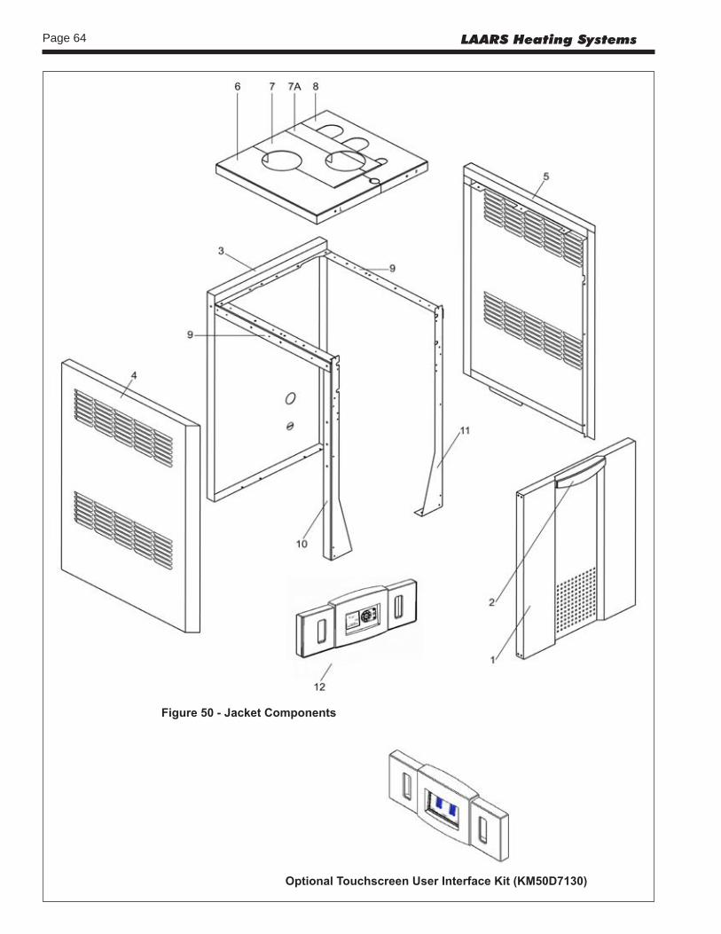
Page 64 LAARS Heating Systems
Figure50-JacketComponents
OptionalTouchscreenUserInterfaceKit(KM50D7130)

Page 65NEOTHERM Boilers and Water Heaters
Figure51a-InternalComponents,Sizes80–210 Figure51b-InternalComponents,Sizes285–600

Page 66 LAARS Heating Systems
Figure51c-InternalComponents,Sizes750-850

Page 67NEOTHERM Boilers and Water Heaters
Figure52a-GasTrainComponents,Sizes80-500
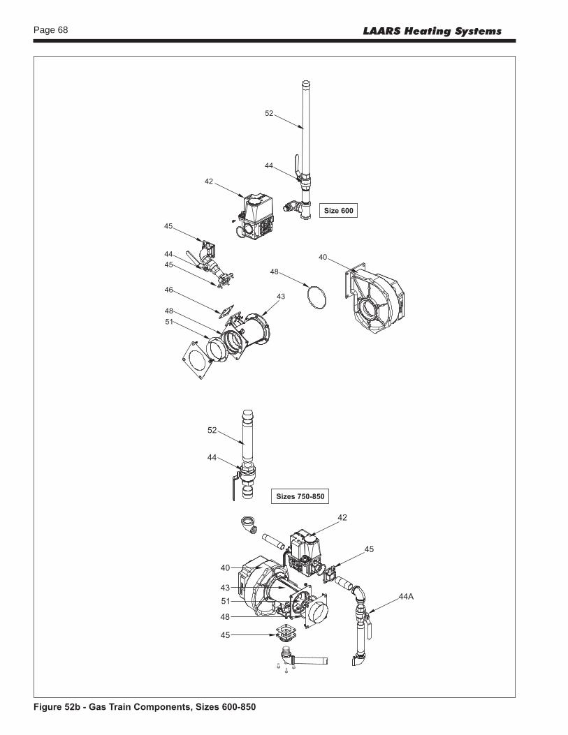
Page 68 LAARS Heating Systems
Figure52b-GasTrainComponents,Sizes600-850

Page 69NEOTHERM Boilers and Water Heaters
Figure53-HeatExchangerComponents
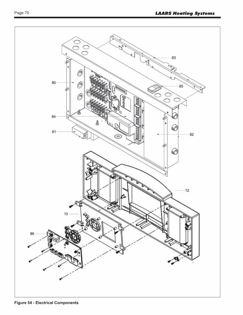
Page 70 LAARS Heating Systems
Figure54-ElectricalComponents
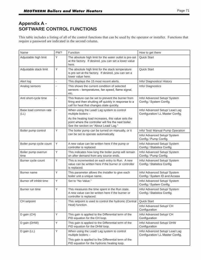
Page 71NEOTHERM Boilers and Water Heaters
AppendixA-SOFTWARE CONTROL FUNCTIONSThis table includes a listing of all of the control functions that can be used by the operator or installer. Functions that require a password are indicated in the second column.
Name PW? Function How to get thereAdjustable high limit Y The absolute high limit for the water outlet is pre-set
at the factory. If desired, you can set a lower value here.
Quick Start
Adjustable stack limit Y The absolute high limit for the stack temperature is pre-set at the factory. If desired, you can set a lower value here.
Quick Start
Alert log - This displays the 15 most recent alerts. Info/ Diagnostics/ HistoryAnalog sensors - This shows the current condition of selected
sensors – temperatures, fan speed, flame signal, etc.
Info/ Diagnostics
Anti short-cycle time - This feature can be set to prevent the burner from firing and then shutting off quickly in response to a call for heat that changes state quickly.
Info/ Advanced Setup/ System Config./ System Config.
Base load common rate (LL)
- When using the Lead/ Lag system to control multiple boilers –As the heating load increases, this value sets the point where the controller will fire the next boiler. See the section on “About Lead/ Lag.”
Info/ Advanced Setup/ Lead Lag Configuration/ LL Master Config.
Boiler pump control Y The boiler pump can be turned on manually, or it can be set to operate automatically.
Info/ Test/ Manual Pump OperationInfo/ Advanced Setup/ System Config./ Pump Config.
Boiler pump cycle count Y A new value can be written here if the pump or controller is replaced.
Info/ Advanced Setup/ System Config./ Statistics Config.
Boiler pump overrun time
Y This indicates how long the boiler pump will remain on after demand from any source ends.
Info/ Advanced Setup/ System Config./ Pump Config.
Burner cycle count Y This is incremented on each entry to Run. A new value can be written here if the burner or controller is replaced.
Info/ Advanced Setup/ System Config./ Statistics Config.
Burner name Y This parameter allows the installer to give each boiler unit a unique name.
Info/ Advanced Setup/ System Config./ System ID and Access
Burner off inhibit time Y Set to “No Value.” Info/ Advanced Setup/ System Config./ System Config.
Burner run time Y This measures the time spent in the Run state. A new value can be written here if the burner or controller is replaced.
Info/ Advanced Setup/ System Config./ Statistics Config.
CH setpoint - This setpoint is used to control the hydronic (Central Heat) function.
Quick StartInfo/ Advanced Setup/ CH Configuration
D gain (CH) Y This gain is applied to the Differential term of the PID equation for the CH loop.
Info/ Advanced Setup/ CH Configuration
D gain (DHW) Y This gain is applied to the Differential term of the PID equation for the DHW loop.
Info/ Advanced Setup/ DHW Configuration
D gain (LL) Y When using the Lead/ Lag system to control multiple boilers –This gain is applied to the Differential term of the PID equation for the hydronic heating loop.
Info/ Advanced Setup/ Lead Lag Configuration/ LL Master Config.

Page 72 LAARS Heating Systems
Name PW? Function How to get thereDemand switch (CH) - Set to “STAT terminal.” Info/ Advanced Setup/ CH
ConfigurationDHW pump control Y The boiler pump can be turned on manually, or it
can be set to operate automatically.Info/ Test/ Manual Pump OperationInfo/ Advanced Setup/ System Config./ Pump Config.
DHW pump cycle count Y A new value can be written here if the pump or controller is replaced.
Info/ Advanced Setup/ System Config./ Statistics Config.
DHW pump overrun time Y This indicates how long the DHW pump will remain on after demand from any source ends.
Info/ Advanced Setup/ System Config./ Pump Config.
DHW setpoint - This setpoint is used to control the Domestic Hot Water function.
Quick StartInfo/ Advanced Setup/ DHW Configuration
Digital I/O - This shows the status of selected switches and valves that are either On or Off.
Info/ Diagnostics
Display setup - Use this to change the lines that appear at the top of the Home display, and to set the brightness of the display.
Info/ Display Setup
General configuration - Used by the Laars factory. Info/ Advanced Setup/ System Config./ System Config.
I gain (CH) Y This gain is applied to the Integral term of the PID equation for the CH loop.
Info/ Advanced Setup/ CH Configuration
I gain (DHW) Y This gain is applied to the Integral term of the PID equation for the DHW loop.
Info/ Advanced Setup/ DHW Configuration
I gain (LL) Y When using the Lead/ Lag system to control multiple boilers –This gain is applied to the Integral term of the PID equation for the hydronic heating loop.
Info/ Advanced Setup/ Lead Lag Configuration/ LL Master Config.
Installer password Y This can only be changed by a user with the OEM-level password.
Info/ Advanced Setup/ System Config./ System ID and Access
LCD contrast - Use this to change the brightness of the display. Info/ Display SetupLockout history - This displays the 15 most recent lockouts. Info/ Diagnostics/ HistoryLow water temp. (CH) - Used with Outdoor Reset –
Above the point where Outdoor Reset stops adjusting for a higher outdoor temperature (the Max. Outdoor Temperature value), this parameter is used as the setpoint.
Quick StartInfo/ Advanced Setup/ CH Configuration/ Outdoor Reset Config.
Low water temp. (LL) - When using the Lead/ Lag system to control multiple boilers, with Outdoor Reset enabled –Above the point where Outdoor Reset stops adjusting for a higher outdoor temperature (the Max. Outdoor Temperature value), this parameter is used as the setpoint.
Info/ Advanced Setup/ Lead Lag Configuration/ LL Outdoor Reset
Manual burner operation Y During testing, use this to turn the burner on and off. Info/ TestMaster enable (LL) - When using the Lead/ Lag system to control
multiple boilers –One of the controllers must be set up as the Lead/Lag Master to supervise the Lead/lag system. The master function must be disabled on all of the other controllers. See the section on “About Lead/Lag.”
Info/ Advanced Setup/ Lead Lag Configuration/ LL Master Config.

Page 73NEOTHERM Boilers and Water Heaters
Name PW? Function How to get thereMax. outdoor temp. (CH) - Used with Outdoor Reset –
This is the maximum outdoor temperature at which the Outdoor Reset feature will be active. Above this point, the Low Water Temp. will be used as the setpoint.
Quick StartInfo/ Advanced Setup/ CH Configuration/ Outdoor Reset Config.
Max. outdoor temp. (LL) - When using the Lead/ Lag system to control multiple boilers, with Outdoor Reset enabled –This is the maximum outdoor temperature at which the Outdoor Reset feature will be active.
Info/ Advanced Setup/ Lead Lag Configuration/ LL Outdoor Reset
MB1 Modbus address - Allows for a specific address assignment for each control in the system (1-8).
Info/ Advanced Setup/ System Config./ System ID and Access
MB2 Modbus address - Allows for a specific address assignment for each control in the system (1-8).
Info/ Advanced Setup/ System Config./ System ID and Access
Min. boiler water temp. (CH)
- Used with Outdoor Reset –If a value is entered here, the temperature in the boiler will never be allowed to drop below this temperature. This will protect the boiler against possible damage due to expansion of ice inside the unit. (Notice that this is different from the “Low Water Temperature” described above.)
Info/ Advanced Setup/ CH Configuration/ Outdoor Reset Config.
Min. outdoor temp. (CH) - Used with Outdoor Reset –This is the maximum outdoor temperature at which the Outdoor Reset feature will be active. Below this point, the system will use the normal CH setpoint.
Quick StartInfo/ Advanced Setup/ CH Configuration/ Outdoor Reset Config.
Min. outdoor temp. (LL) - When using the Lead/ Lag system to control multiple boilers, with Outdoor Reset enabled –This is the maximum outdoor temperature at which the Outdoor Reset feature will be active. Below this point, the system will use the normal LL setpoint.
Info/ Advanced Setup/ Lead Lag Configuration/ LL Outdoor Reset
Min. water temp. (LL) - When using the Lead/ Lag system to control multiple boilers, with Outdoor Reset enabled –If a value is entered here, the temperature in the boiler will never be allowed to drop below this temperature. This will protect the boiler against possible damage due to expansion of ice inside the unit. (Notice that this is different from the “Low Water Temperature” described above.)
Info/ Advanced Setup/ Lead Lag Configuration/ LL Outdoor Reset
Modbus address - When using the Lead/ Lag system to control multiple boilers –Each controller must have a unique Modbus address.
Info/ Advanced Setup/ System Config./ System ID and Access
Modulation sensor - Used with external modulation control –The choices are Outlet/ Inlet/ S5, S10, and None.
Info/ Advanced Setup/ CH Configuration
OEM ID Y Cannot be changed by the Installer. Info/ Advanced Setup/ System Config./ System ID and Access
OEM password Y Cannot be changed by the installer. Info/ Advanced Setup/ System Config./ System ID and Access
Off hysteresis (CH) - For hydronic heating (Central Heat) –The control system will not shut off the boiler until the temperature at the System sensor rises to the CH setpoint plus a hysteresis value (normally about 10°F).
Info/ Advanced Setup/ CH Configuration
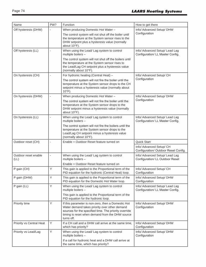
Page 74 LAARS Heating Systems
Name PW? Function How to get thereOff hysteresis (DHW) - When producing Domestic Hot Water –
The control system will not shut off the boiler until the temperature at the System sensor rises to the DHW setpoint plus a hysteresis value (normally about 10°F).
Info/ Advanced Setup/ DHW Configuration
Off hysteresis (LL) - When using the Lead/ Lag system to control multiple boilers –The control system will not shut off the boilers until the temperature at the System sensor rises to the Lead/Lag CH setpoint plus a hysteresis value (normally about 10°F).
Info/ Advanced Setup/ Lead Lag Configuration/ LL Master Config.
On hysteresis (CH) - For hydronic heating (Central Heat) –The control system will not fire the boiler until the temperature at the System sensor drops to the CH setpoint minus a hysteresis value (normally about 10°F).
Info/ Advanced Setup/ CH Configuration
On hysteresis (DHW) - When producing Domestic Hot Water –The control system will not fire the boiler until the temperature at the System sensor drops to the DHW setpoint minus a hysteresis value (normally about 10°F).
Info/ Advanced Setup/ DHW Configuration
On hysteresis (LL) - When using the Lead/ Lag system to control multiple boilers –The control system will not fire the boilers until the temperature at the System sensor drops to the Lead/Lag CH setpoint minus a hysteresis value (normally about 10°F).
Info/ Advanced Setup/ Lead Lag Configuration/ LL Master Config.
Outdoor reset (CH) - Enable = Outdoor Reset feature turned on Quick StartInfo/ Advanced Setup/ CH Configuration/ Outdoor Reset Config.
Outdoor reset enable (LL)
- When using the Lead/ Lag system to control multiple boilers –Enable = Outdoor Reset feature turned on
Info/ Advanced Setup/ Lead Lag Configuration/ LL Outdoor Reset
P gain (CH) Y This gain is applied to the Proportional term of the PID equation for the hydronic (Central Heat) loop.
Info/ Advanced Setup/ CH Configuration
P gain (DHW) Y This gain is applied to the Proportional term of the PID equation for the Domestic Hot Water loop.
Info/ Advanced Setup/ DHW Configuration
P gain (LL) Y When using the Lead/ Lag system to control multiple boilers –This gain is applied to the Proportional term of the PID equation for the hydronic loop.
Info/ Advanced Setup/ Lead Lag Configuration/ LL Master Config.
Priority time Y If this parameter is non-zero, then a Domestic Hot Water demand takes priority over other demand sources for the specified time. The priority override timing is reset when demand from the DHW source turns off.
Info/ Advanced Setup/ DHW Configuration
Priority vs Central Heat Y If a CH call and a DHW call arrive at the same time, which has priority?
Info/ Advanced Setup/ DHW Configuration
Priority vs Lead/Lag Y When using the Lead/ Lag system to control multiple boilers –If a call for hydronic heat and a DHW call arrive at the same time, which has priority?
Info/ Advanced Setup/ DHW Configuration

Page 75NEOTHERM Boilers and Water Heaters
Name PW? Function How to get therePump exercise interval Y The system can be set to exercise the pumps at
set intervals. Enter a non-zero value to turn on the function.
Info/ Advanced Setup/ System Config./ Pump Config.
Pump exercise time Y If the pump exercise feature is enabled, this value sets the length of time that each pump will be exercised.
Info/ Advanced Setup/ System Config./ Pump Config.
Set high fire Y This is used during combustion setup to set the “high fire” condition.
Info/ Test/ Forced Rate
Set low fire Y This is used during combustion setup to set the “low fire” condition.
Info/ Test/ Forced Rate
Setpoint (LL) - When using the Lead/ Lag system to control multiple boilers –This setpoint is used to control the hydronic (Central Heat) function.
Info/ Advanced Setup/ Lead Lag Configuration/ LL Master Config.
Setpoint source (CH) Y Set to “Local.” Info/ Advanced Setup/ CH Configuration
Setpoint source (LL) Y When using the Lead/ Lag system to control multiple boilers –Set to “Local.”
Info/ Advanced Setup/ Lead Lag Configuration/ LL Master Config.
Slave enable (LL) - When using the Lead/ Lag system to control multiple boilers –One of the controllers must be set up as the Lead/Lag Master to supervise the Lead/lag system. The controllers on all of the other boilers must be enabled as slaves. See the section on “About Lead/Lag.”The choices are: Disable/ Enable via Modbus Master/ Enable via SOLA Master
Info/ Advanced Setup/ Lead Lag Configuration/ LL Slave Config.
Slave mode (LL) Y When using the Lead/ Lag system to control multiple boilers –Set to “Equal Run Time.”
Info/ Advanced Setup/ Lead Lag Configuration/ LL Slave Config.
Start test Y This is used during combustion setup to start the test firing.
Info/ Test
System pump control Y The System pump can be turned on manually, or it can be set to operate automatically.
Info/ Test/ Manual Pump OperationInfo/ Advanced Setup/ System Config./ Pump Config.
System pump overrun time
Y This indicates how long the System pump will remain on after demand from any source ends.
Info/ Advanced Setup/ System Config./ Pump Config.
Temperature units - Fahrenheit or Celsius Info/ Advanced Setup/ System Config./ System Config.
Warm weather shutdown Y The system can be set to shut down if the outdoor temperature rises above a certain value.
Info/ Advanced Setup/ CH Configuration/ Warm Weather Shutdown
Warm weather shutdown setpoint
- If warm weather shutdown is enabled –If the outdoor temperature is higher than this value, the system will be shut off for Central Heating functions.
Info/ Advanced Setup/ CH Configuration/ Warm Weather Shutdown
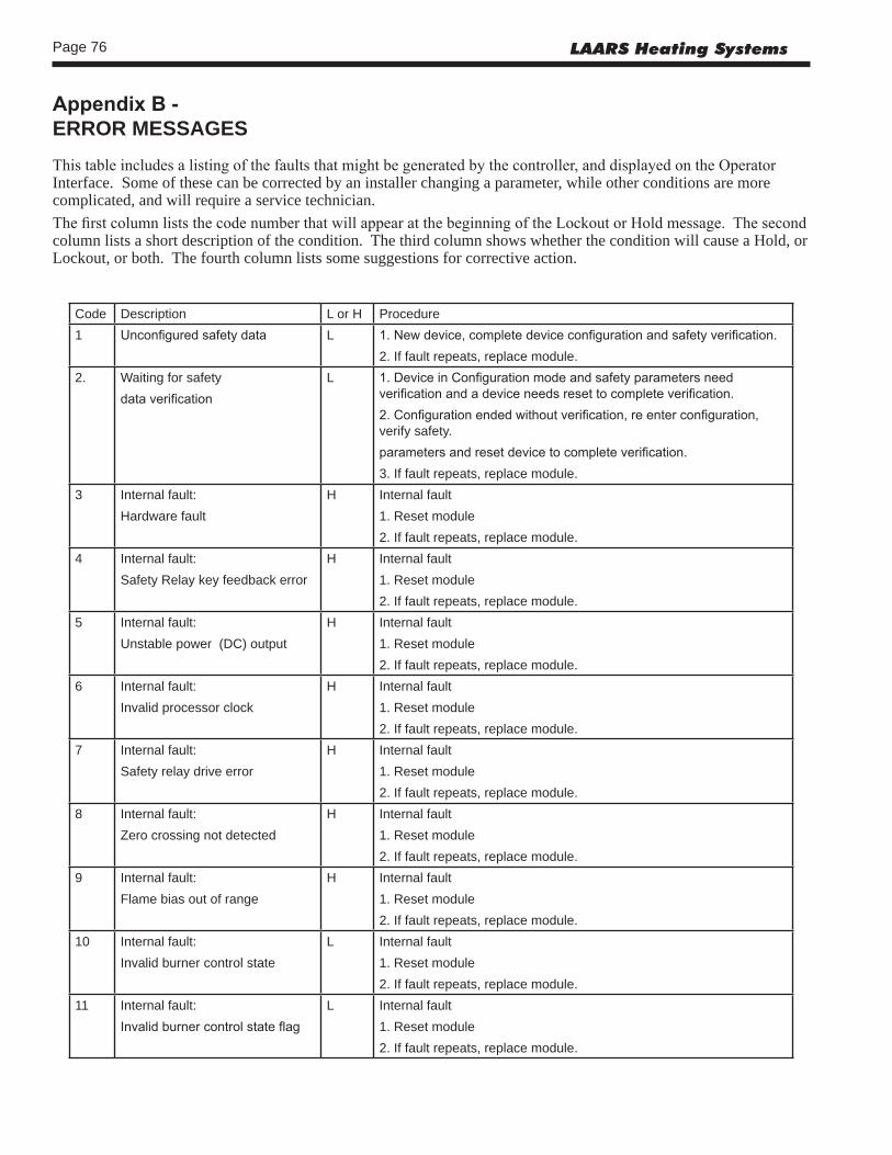
Page 76 LAARS Heating Systems
AppendixB-ERROR MESSAGESThis table includes a listing of the faults that might be generated by the controller, and displayed on the Operator Interface. Some of these can be corrected by an installer changing a parameter, while other conditions are more complicated, and will require a service technician.The first column lists the code number that will appear at the beginning of the Lockout or Hold message. The second column lists a short description of the condition. The third column shows whether the condition will cause a Hold, or Lockout, or both. The fourth column lists some suggestions for corrective action.
Code Description L or H Procedure1 Unconfigured safety data L 1. New device, complete device configuration and safety verification.
2. If fault repeats, replace module.2. Waiting for safety
data verificationL 1. Device in Configuration mode and safety parameters need
verification and a device needs reset to complete verification.2. Configuration ended without verification, re enter configuration, verify safety.parameters and reset device to complete verification.3. If fault repeats, replace module.
3 Internal fault:Hardware fault
H Internal fault1. Reset module2. If fault repeats, replace module.
4 Internal fault:Safety Relay key feedback error
H Internal fault1. Reset module2. If fault repeats, replace module.
5 Internal fault:Unstable power (DC) output
H Internal fault1. Reset module2. If fault repeats, replace module.
6 Internal fault:Invalid processor clock
H Internal fault1. Reset module2. If fault repeats, replace module.
7 Internal fault:Safety relay drive error
H Internal fault1. Reset module2. If fault repeats, replace module.
8 Internal fault:Zero crossing not detected
H Internal fault1. Reset module2. If fault repeats, replace module.
9 Internal fault:Flame bias out of range
H Internal fault1. Reset module2. If fault repeats, replace module.
10 Internal fault:Invalid burner control state
L Internal fault1. Reset module2. If fault repeats, replace module.
11 Internal fault:Invalid burner control state flag
L Internal fault1. Reset module2. If fault repeats, replace module.

Page 77NEOTHERM Boilers and Water Heaters
12 Internal fault:Safety relay drive cap short
H Internal fault1. Reset module2. If fault repeats, replace module.
13 Internal fault:PII (Pre-Ignition Interlock) shorted to ILK (Interlock)
H or L Internal fault1. Reset module2. If fault repeats, replace module.
15 Internal fault:Safety relay test failed due to feedback ON
L Internal fault1. Reset module2. If fault repeats, replace module.
16 Internal fault:Safety relay test failed due to safety relay OFF
L Internal fault1. Reset module2. If fault repeats, replace module.
17 Internal fault:Safety relay test failed due to safety relay not OFF
L Internal fault1. Reset module2. If fault repeats, replace module.
18 Internal fault:Safety relay test failed due to feedback not ON
L Internal fault1. Reset module2. If fault repeats, replace module.
19 Internal fault:Safety RAM write
L Internal fault1. Reset module2. If fault repeats, replace module.
20 Internal fault:Internal fault: Flame ripple and overflow
H Internal fault1. Reset module2. If fault repeats, replace module.
21 Internal fault:Flame number of sample mismatch
H Internal fault1. Reset module2. If fault repeats, replace module.
22 Internal fault:Flame bias out of range
H Internal fault1. Reset module2. If fault repeats, replace module.
23 Internal fault:Bias changed since heating cycle starts
H Internal fault1. Reset module2. If fault repeats, replace module.
24 Internal fault:Spark voltage stuck low or high
H Internal fault1. Reset module2. If fault repeats, replace module.
25 Internal fault:Spark voltage changed too much during flame sensing time
H Internal fault1. Reset module2. If fault repeats, replace module.
26 Internal fault:Static flame ripple
H Internal fault1. Reset module2. If fault repeats, replace module.
Code Description L or H Procedure

Page 78 LAARS Heating Systems
27 Internal fault:Flame rod shorted to ground detected
H Internal fault1. Reset module2. If fault repeats, replace module.
28 Internal fault:A/D linearity test fails
H Internal fault1. Reset module2. If fault repeats, replace module.
29 Internal fault:Flame bias cannot be set in range
H Internal fault1. Reset module2. If fault repeats, replace module.
30 Internal fault:Flame bias shorted to adjacent pin
H Internal fault1. Reset module2. If fault repeats, replace module.
31 Internal fault:SLO electronics unknown error
H Internal fault1. Reset module2. If fault repeats, replace module.
32-46 Internal fault:Safety Key 0 through 14
L Internal fault1. Reset module2. If fault repeats, replace module.
47 Flame Rod to ground leakage H Internal fault1. Reset module2. If fault repeats, replace module.
48 Static flame (not flickering) H Internal fault1. Reset module2. If fault repeats, replace module.
49 24 VAC voltage low/high H 1. Check the module and display connections.2. Check the module power supply and make sure that frequency, voltage and VA meet the specifications.
50 Modulation fault H Internal sub-system fault.1. Review alert messages for possible trends.2. Correct possible problems.
51 Pump fault H Internal sub-system fault.1. Review alert messages for possible trends.2. Correct possible problems.
52 Motor tachometer fault H Internal sub-system fault.1. Review alert messages for possible trends.2. Correct possible problems.
53 AC input phases reversed L 1. Check the module and display connections.2. Check the module power supply and make sure that both frequency and voltage meet the specifications.3. On 24 VAC applications, assure that J4 terminal 10 and J8 terminal 2 are connected together.
59 Internal Fault: Mux pin shorted L Internal Fault.1. Reset module.2. If fault repeats, replace module.
61 Anti short cycle H Will not be a lockout fault. Hold Only.
62 Fan speed not proved H Will not be a lockout fault. Hold Only.
Code Description L or H Procedure

Page 79NEOTHERM Boilers and Water Heaters
63 LCI (Limit Control Input) OFF(Safety Chain Open)
H 1. Check wiring and correct any faults.2. Check Interlocks connected to the LCI to assure proper function.3. Reset and sequence the module; monitor the LCI status.4. If code persists, replace the module
64 PII (Pre-Ignition Interlock) OFF H or L 1. Check wiring and correct any faults.2. Check Preignition Interlock switches to assure proper functioning.3. Check the valve operation.4. Reset and sequence the module; monitor the PII status.5. If code persists, replace the module.
67 ILK (Interlock) OFF H or L 1. Check wiring and correct any possible shorts.2. Check Interlock (ILK) switches to assure proper function.3. Verify voltage through the interlock string to the interlock input with a voltmeter.4. If steps 1-3 are correct and the fault persists, replace the module.
68 ILK (Interlock) ON H or L 1. Check wiring and correct any possible shorts.2. Check Interlock (ILK) switches to assure proper function.3. Verify voltage through the interlock string to the interlock input with a voltmeter.4. If steps 1-3 are correct and the fault persists, replace the module.
70 Wait for leakage test completion H 1. Internal Fault. Reset module.2. If fault repeats, replace module.
78 Demand Lost in Run H 1. Check wiring and correct any possible errors.2. If previous steps are correct and fault persists, replace the module.
79 Outlet high limit H or L 1. Check wiring and correct any possible errors.2. Replace the outlet high limit.3. If previous steps are correct and fault persists, replace the module.
80 DHW (Domestic Hot Water) high limit
H or L 1. Check wiring and correct any possible errors.2. Replace the DHW high limit.3. If previous steps are correct and fault persists, replace the module.
81 Delta T limit H or L 1. Check inlet and outlet sensors and pump circuits for proper operation.2. Recheck the Delta T Limit to confirm proper setting.3. If previous steps are correct and fault persists, replace the module.
82 Stack limit H or L 1. Check wiring and correct any possible errors.2. Replace the Stack high limit.3. If previous steps are correct and fault persists, replace the module.
91 Inlet sensor fault H 1. Check wiring and correct any possible errors.2. Replace the Inlet sensor.3. If previous steps are correct and fault persists, replace the module.
92 Outlet sensor fault H 1. Check wiring and correct any possible errors.2. Replace the Outlet sensor.3. If previous steps are correct and fault persists, replace the module.
93 DHW (Domestic Hot Water) sensor fault
H 1. Check wiring and correct any possible errors.2. Replace the DHW sensor.3. If previous steps are correct and fault persists, replace the module.
Code Description L or H Procedure

Page 80 LAARS Heating Systems
94 Header sensor fault H 1. Check wiring and correct any possible errors.2. Replace the header sensor.3. If previous steps are correct and fault persists, replace the module.
95 Stack sensor fault H 1. Check wiring and correct any possible errors.2. Replace the stack sensor.3. If previous steps are correct and fault persists, replace the module.
96 Outdoor sensor fault H 1. Check wiring and correct any possible errors.2. Replace the outdoor sensor.3. If previous steps are correct and fault persists, replace the module.
97 Internal Fault: A2D mismatch. L Internal Fault.1. Reset module.2. If fault repeats, replace module.
98 Internal Fault: Exceeded VSNSR voltage tolerance
L Internal Fault.1. Reset module.2. If fault repeats, replace module.
99 Internal Fault: Exceeded 28V voltage tolerance
L Internal Fault.1. Reset module.2. If fault repeats, replace module.
100 Pressure Sensor Fault H 1. Verify the pressure sensor is a 4-20 mA source.2. Check wiring and correct any possible errors.3. Test the pressure sensor for correct operation.4. Replace the pressure sensor.5. If previous steps are correct and fault persists, replace the module.
105 Flame detected out of sequence H or L 1. Check that flame is not present in the combustion chamber. Correct any errors.2. Make sure that the flame detector is wired to the correct terminal.3. Make sure the F & G wires are protected from stray noise pickup.4. Reset and sequence the module. If code reappears, replace the flame detector.5. Reset and sequence the module. If code reappears, replace the module.
106 Flame lost in MFEP L 1. Check main valve wiring and operation - correct any errors.2. Check the fuel supply.3. Check fuel pressure and repeat turndown tests.4. Check ignition transformer electrode, flame detector, flame detector siting or flame rod position.5. If steps 1 through 4 are correct and the fault persists, replace the module.
107 Flame lost early in run L 1. Check main valve wiring and operation - correct any errors.2. Check the fuel supply.3. Check fuel pressure and repeat turndown tests.4. Check ignition transformer electrode, flame detector, flame detector siting or flame rod position.5. If steps 1 through 4 are correct and the fault persists, replace the module.
Code Description L or H Procedure

Page 81NEOTHERM Boilers and Water Heaters
108 Flame lost in run L 1. Check main valve wiring and operation - correct any errors.2. Check the fuel supply.3. Check fuel pressure and repeat turndown tests.4. Check ignition transformer electrode, flame detector, flame detector siting or flame rod position.5. If steps 1 through 4 are correct and the fault persists, replace the module.
109 Ignition failed L 1. Check the main valve wiring and operation - correct any errors.2. Check the fuel supply.3. Check fuel pressure and repeat turndown tests.4. Check ignition transformer electrode, flame detector, flame detector siting or flame rod position.5. If steps 1 through 4 are correct and the fault persists, replace the module.
110 Ignition failure occurred H Hold time of recycle and hold option. Will not be a lockout fault. Hold only. Internal hardware test. Not a lockout.
111 Flame current lower than weak threshold
H Hold time of recycle and hold option. Will not be a lockout fault. Hold only. Internal hardware test. Not a lockout.
113 Flame circuit timeout L Flame sensed during initiate or off cycle. Produces a Hold for 240 seconds. If still present after 240 seconds, system will lockout.
122 Lightoff rate proving failed L 1. Check wiring and correct any potential wiring errors.2. Check VFD’s (Variable-speed Fan Drive) ability to change speeds.3. Change the VFD4. If the fault persists, replace the module.
123 Purge rate proving failed L 1. Check wiring and correct any potential wiring errors.2. Check VFD’s (Variable-speed Fan Drive) ability to change speeds.3. Change the VFD4. If the fault persists, replace the module.
128 Fan speed failed during prepurge H or L 1. Check wiring and correct any potential wiring errors.2. Check the VFDs (Variable-speed Fan Drive) ability to change speeds.3. Change the VFD4. If the fault persists, replace the module.
129 Fan speed failed during preignition
H or L 1. Check wiring and correct any potential wiring errors.2. Check the VFDs (Variable-speed Fan Drive) ability to change speeds.3. Change the VFD4. If the fault persists, replace the module.
130 Fan speed failed during ignition H or L 1. Check wiring and correct any potential wiring errors.2. Check the VFDs (Variable-speed Fan Drive) ability to change speeds.3. Change the VFD4. If the fault persists, replace the module.
131 Fan movement detected during standby
H 1. Check wiring and correct any potential wiring errors.2. Check the VFDs (Variable-speed Fan Drive) ability to change speeds.3. Change the VFD4. If the fault persists, replace the module.
Code Description L or H Procedure

Page 82 LAARS Heating Systems
132 Fan speed failed during run H 1. Check wiring and correct any potential wiring errors.2. Check the VFDs (Variable-speed Fan Drive) ability to change speeds.3. Change the VFD4. If the fault persists, replace the module.
137 ILK (Interlock) failed to close H 1. Check wiring and correct any possible shorts.2. Check Interlock (ILK) switches to assure proper function.3. Verify voltage through the interlock string to the interlock input with a voltmeter.4. If steps 1-3 are correct and the fault persists, replace the module.
149 Flame detected H or L Create a Hold if a flame is detected during Safe Start check up to Flame Establishing period.
150 Flame not detected H Sequence returns to standby and restarts sequence at the beginning of Purge after the HF switch opens if flame detected during Safe Start check up to Flame Establishing period.
154 Purge Fan switch On H or L 1. Purge fan switch is on when it should be off.2. Check wiring and correct any errors.3. Inspect the Purge Fan switch J6 terminal 3 and its connections. Make sure the switch is working correctly and is not jumpered or welded.4. Reset and sequence the relay module.5. If the fault persists, replace the relay module.
155 Purge fan switch Off H or L 1. Purge fan switch is off when it should be on.2. Check wiring and correct any errors.3. Inspect the Purge Fan switch J6 terminal 3 and its connections. Make sure the switch is working correctly and is not jumpered or welded.4. Reset and sequence the relay module.5. If the fault persists, replace the relay module.
156 Combustion pressure and flame On
H or L 1. Check that flame is not present in the combustion chamber. Correct any errors.2. Make sure that the flame detector is wired to the correct terminal.3. Make sure the F & G wires are protected from stray noise pickup.4. Reset and sequence the module, if code reappears, replace the flame detector.5. Reset and sequence the module, if code reappears, replace the module.
157 Combustion pressure and flame Off
L 1. Check that flame is not present in the combustion chamber. Correct any errors.2. Make sure that the flame detector is wired to the correct terminal.3. Make sure the F & G wires are protected from stray noise pickup.4. Reset and sequence the module, if code reappears, replace the flame detector.5. Reset and sequence the module, if code reappears, replace the module.
158 Main valve On L 1. Check the main valve terminal wiring and correct any errors.2. Reset and sequence the module. If fault persists, replace the module.
Code Description L or H Procedure

Page 83NEOTHERM Boilers and Water Heaters
159 Main valve Off L 1. Check the main valve terminal wiring and correct any errors.2. Reset and sequence the module. If fault persists, replace the module.
160 Ignition On L 1. Check Ignition terminal wiring and correct any errors.2. Reset and sequence the module. If fault persists, replace the module.
161 Ignition Off L 1. Check the ignition terminal wiring and correct any errors.2. Reset and sequence the module. If fault persists, replace the module.
164 Block intake On L 1. Check wiring and correct any errors.2. Inspect the Block Intake Switch to make sure it is working correctly.3. Reset and sequence the module.4. During Standby and Purge, measure the voltage across the switch. Supply voltage should be present. If not, the Block Intake Switch is defective and needs replacing.5. If the fault persists, replace the relay module.
165 Block intake Off L 1. Check wiring and correct any errors.2. Inspect the Block Intake Switch to make sure it is working correctly.3. Reset and sequence the module.4. During Standby and Purge, measure the voltage across the switch. Supply voltage should be present. If not, the Block Intake Switch is defective and needs replacing.5. If the fault persists, replace the relay module.
172 Main relay feedback incorrect L Internal fault.1. Reset module.2. If fault repeats, replace module.
174 Safety relay feedback incorrect L Internal fault.1. Reset module.2. If fault repeats, replace module.
175 Safety relay open L Internal fault.1. Reset module.2. If fault repeats, replace module.
176 Main relay On at safe start check L Internal fault.1. Reset Module.2. If fault repeats, replace module.
178 Safety relay On at safe start check
L Internal fault.1. Reset module.2. If fault repeats, replace module.
184 Invalid Blower/ HSI output setting L 1. Recheck selected parameters, reverify and reset module.2. If fault repeats, verify electrical grounding.3. If fault repeats, replace module.
185 Invalid Delta T limit enable setting
L 1. Recheck selected parameters, reverify and reset module.2. If fault repeats, verify electrical grounding.3. If fault repeats, replace module.
186 Invalid Delta T limit response setting
L 1. Recheck selected parameters, reverify and reset module.2. If fault repeats, verify electrical grounding.3. If fault repeats, replace module.
Code Description L or H Procedure

Page 84 LAARS Heating Systems
187 Invalid DHW (Domestic Hot Water) high limit enable setting
L 1. Recheck selected parameters, reverify and reset module.2. If fault repeats, verify electrical grounding.3. If fault repeats, replace module.
188 Invalid DHW (Domestic Hot Water) high limit response setting
L 1. Recheck selected parameters, reverify and reset module.2. If fault repeats, verify electrical grounding.3. If fault repeats, replace module.
189 Invalid flame sensor type setting L 1. Recheck selected parameters, reverify and reset module.2. If fault repeats, verify electrical grounding.3. If fault repeats, replace module.
192 Invalid igniter on during setting L 1. Recheck selected parameters, reverify and reset module.2. If fault repeats, verify electrical grounding.3. If fault repeats, replace module.
193 Invalid ignite failure delay setting L 1. Recheck selected parameters, reverify and reset module.2. If fault repeats, verify electrical grounding.3. If fault repeats, replace module.
194 Invalid ignite failure response setting
L 1. Recheck selected parameters, reverify and reset module.2. If fault repeats, verify electrical grounding.3. If fault repeats, replace module.\
195 Invalid ignite failure retries setting L 1. Recheck selected parameters, reverify and reset module.2. If fault repeats, verify electrical grounding.3. If fault repeats, replace module.
196 Invalid ignition source setting L 1. Recheck selected parameters, reverify and reset module.2. If fault repeats, verify electrical grounding.3. If fault repeats, replace module.
197 Invalid interlock open response setting
L 1. Recheck selected parameters, reverify and reset module.2. If fault repeats, verify electrical grounding.3. If fault repeats, replace module.
198 Invalid interlock start check setting
L 1. Recheck selected parameters, reverify and reset module.2. If fault repeats, verify electrical grounding.3. If fault repeats, replace module.
199 Invalid LCI (Limit Control Input) enable setting
L 1. Recheck selected parameters, reverify and reset module.2. If fault repeats, verify electrical grounding.3. If fault repeats, replace module.
200 Invalid lightoff rate setting L 1. Recheck selected parameters, reverify and reset module.2. If fault repeats, verify electrical grounding.3. If fault repeats, replace module.
201 Invalid lightoff rate proving setting
L 1. Recheck selected parameters, reverify and reset module.2. If fault repeats, verify electrical grounding.3. If fault repeats, replace module.
202 Invalid MFEP (Main Flame Establishing Period) time setting
L 1. Recheck selected parameters, reverify and reset module.2. If fault repeats, verify electrical grounding.3. If fault repeats, replace module.
203 Invalid MFEP (Main Flame Establishing Period) flame failure response setting
L 1. Recheck selected parameters, reverify and reset module.2. If fault repeats, verify electrical grounding.3. If fault repeats, replace module.
Code Description L or H Procedure

Page 85NEOTHERM Boilers and Water Heaters
204 Invalid NTC sensor type setting L 1. Recheck selected parameters, reverify and reset module.2. If fault repeats, verify electrical grounding.3. If fault repeats, replace module.
205 Invalid Outlet high limit response setting
L 1. Recheck selected parameters, reverify and reset module.2. If fault repeats, verify electrical grounding.3. If fault repeats, replace module.
207 Invalid PII (Pre-Ignition Interlock) enable setting
L 1. Recheck selected parameters, reverify and reset module.2. If fault repeats, verify electrical grounding.3. If fault repeats, replace module.
210 Invalid Postpurge time setting L 1. Recheck selected parameters, reverify and reset module.2. If fault repeats, verify electrical grounding.3. If fault repeats, replace module.
211 Invalid Power up with lockout setting
L 1. Recheck selected parameters, reverify and reset module.2. If fault repeats, verify electrical grounding.3. If fault repeats, replace module.
212 Invalid Preignition time setting L 1. Recheck selected parameters, reverify and reset module.2. If fault repeats, verify electrical grounding.3. If fault repeats, replace module.
213 Invalid Prepurge rate setting L 1. Recheck selected parameters, reverify and reset module.2. If fault repeats, verify electrical grounding.3. If fault repeats, replace module.
214 Invalid Prepurge time setting L 1. Recheck selected parameters, reverify and reset module.2. If fault repeats, verify electrical grounding.3. If fault repeats, replace module.
215 Invalid Purge rate proving setting L 1. Recheck selected parameters, reverify and reset module.2. If fault repeats, verify electrical grounding.3. If fault repeats, replace module.
216 Invalid Run flame failure response setting
L 1. Recheck selected parameters, reverify and reset module.2. If fault repeats, verify electrical grounding.3. If fault repeats, replace module.
217 Invalid Run stabilization time setting
L 1. Recheck selected parameters, reverify and reset module.2. If fault repeats, verify electrical grounding.3. If fault repeats, replace module.
218 Invalid Stack limit enable setting L 1. Recheck selected parameters, reverify and reset module.2. If fault repeats, verify electrical grounding.3. If fault repeats, replace module.
219 Invalid Stack limit response setting
L 1. Recheck selected parameters, reverify and reset module.2. If fault repeats, verify electrical grounding.3. If fault repeats, replace module.
220 Unconfigured Delta T limit setpoint setting
L 1. Recheck selected parameters, reverify and reset module.2. If fault repeats, verify electrical grounding.3. If fault repeats, replace module.
221 Unconfigured DHW (Domestic Hot Water) high limit setpoint setting
L 1. Recheck selected parameters, reverify and reset module.2. If fault repeats, verify electrical grounding.3. If fault repeats, replace module.
Code Description L or H Procedure

Page 86 LAARS Heating Systems
222 Unconfigured Outlet high limit setpoint setting
L 1. Recheck selected parameters, reverify and reset module.2. If fault repeats, verify electrical grounding.3. If fault repeats, replace module.
223 Unconfigured Stack limit setpoint setting
L 1. Recheck selected parameters, reverify and reset module.2. If fault repeats, verify electrical grounding.3. If fault repeats, replace module.
224 Invalid DHW (Domestic Hot Water) demand source setting
L 1. Recheck selected parameters, reverify and reset module.2. If fault repeats, verify electrical grounding.3. If fault repeats, replace module.
225 Invalid Flame threshold setting L 1. Recheck selected parameters, reverify and reset module.2. If fault repeats, verify electrical grounding.3. If fault repeats, replace module.
226 Invalid Outlet high limit setpoint setting
L 1. Recheck selected parameters, reverify and reset module.2. If fault repeats, verify electrical grounding.3. If fault repeats, replace module.
227 Invalid DHW (Domestic Hot Water) high limit setpoint setting
L 1. Recheck selected parameters, reverify and reset module.2. If fault repeats, verify electrical grounding.3. If fault repeats, replace module.
228 Invalid Stack limit setpoint setting L 1. Recheck selected parameters, reverify and reset module.2. If fault repeats, verify electrical grounding.3. If fault repeats, replace module.
229 Invalid Modulation output setting L 1. Recheck selected parameters, reverify and reset module.2. If fault repeats, verify electrical grounding.3. If fault repeats, replace module.
230 Invalid CH (Central Heat) demand source setting
L 1. Recheck selected parameters, reverify and reset module.2. If fault repeats, verify electrical grounding.3. If fault repeats, replace module.
231 Invalid Delta T limit delay setting L 1. Recheck selected parameters, reverify and reset module.2. If fault repeats, verify electrical grounding.3. If fault repeats, replace module.
232 Invalid Pressure sensor type setting
L 1. Recheck selected parameters, reverify and reset module.2. If fault repeats, verify electrical grounding.3. If fault repeats, replace module.
234 Invalid Outlet high limit enable setting
L 1. Recheck selected parameters, reverify and reset module.2. If fault repeats, verify electrical grounding.3. If fault repeats, replace module.
235 Invalid Outlet connector type setting
L 1. Recheck selected parameters, reverify and reset module.2. If fault repeats, verify electrical grounding.3. If fault repeats, replace module.
236 Invalid Inlet connector type setting
L 1. Recheck selected parameters, reverify and reset module.2. If fault repeats, verify electrical grounding.3. If fault repeats, replace module.
Code Description L or H Procedure

Page 87NEOTHERM Boilers and Water Heaters
237 Invalid DHW (Domestic Hot Water) connector type setting
L 1. Recheck selected parameters, reverify and reset module.2. If fault repeats, verify electrical grounding.3. If fault repeats, replace module.
238 Invalid Stack connector type setting
L 1. Recheck selected parameters, reverify and reset module.2. If fault repeats, verify electrical grounding.3. If fault repeats, replace module.
239 Invalid Header connector type setting
L 1. Recheck selected parameters, reverify and reset module.2. If fault repeats, verify electrical grounding.3. If fault repeats, replace module.
240 Invalid Outdoor connector type setting
L 1. Recheck selected parameters, reverify and reset module.2. If fault repeats, verify electrical grounding.3. If fault repeats, replace module.
Code Description L or H Procedure

H23
5520
0B
800.900.9276 • Fax 800.559.1583 (Customer Service and Product Support)20 Industrial Way, Rochester, NH 03867 • 603.335.6300 • Fax 603.335.3355
1869 Sismet Road, Mississauga, Ontario, Canada L4W 1W8 • 905.238.0100 • Fax 905.366.0130 www.Laars.com Printed in U.S.A. © Laars Heating Systems 1310 Document 1252B
Dimensions and specifications subject to change without notice in accordance with our policy of continuous product improvement.

UNBC BMO Building, Prince George Boiler Plant Upgrade, Project No. 2015387 Issued for Tender September, 2015
BOILER PLANT UPGRADE SPECIFICATIONS
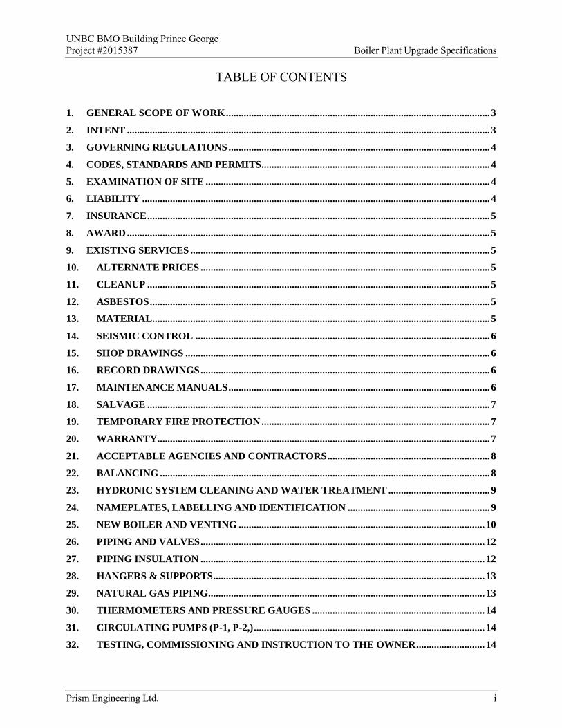
UNBC BMO Building Prince George Project #2015387 Boiler Plant Upgrade Specifications
Prism Engineering Ltd. i
TABLE OF CONTENTS
1. GENERAL SCOPE OF WORK ........................................................................................................ 3
2. INTENT ............................................................................................................................................... 3
3. GOVERNING REGULATIONS ....................................................................................................... 4
4. CODES, STANDARDS AND PERMITS .......................................................................................... 4
5. EXAMINATION OF SITE ................................................................................................................ 4
6. LIABILITY ......................................................................................................................................... 4
7. INSURANCE ....................................................................................................................................... 5
8. AWARD ............................................................................................................................................... 5
9. EXISTING SERVICES ...................................................................................................................... 5
10. ALTERNATE PRICES .................................................................................................................. 5
11. CLEANUP ....................................................................................................................................... 5
12. ASBESTOS ...................................................................................................................................... 5
13. MATERIAL ..................................................................................................................................... 5
14. SEISMIC CONTROL .................................................................................................................... 6
15. SHOP DRAWINGS ........................................................................................................................ 6
16. RECORD DRAWINGS .................................................................................................................. 6
17. MAINTENANCE MANUALS ....................................................................................................... 6
18. SALVAGE ....................................................................................................................................... 7
19. TEMPORARY FIRE PROTECTION .......................................................................................... 7
20. WARRANTY ................................................................................................................................... 7
21. ACCEPTABLE AGENCIES AND CONTRACTORS ................................................................ 8
22. BALANCING .................................................................................................................................. 8
23. HYDRONIC SYSTEM CLEANING AND WATER TREATMENT ........................................ 9
24. NAMEPLATES, LABELLING AND IDENTIFICATION ........................................................ 9
25. NEW BOILER AND VENTING ................................................................................................. 10
26. PIPING AND VALVES ................................................................................................................ 12
27. PIPING INSULATION ................................................................................................................ 12
28. HANGERS & SUPPORTS ........................................................................................................... 13
29. NATURAL GAS PIPING ............................................................................................................. 13
30. THERMOMETERS AND PRESSURE GAUGES .................................................................... 14
31. CIRCULATING PUMPS (P-1, P-2,) ........................................................................................... 14
32. TESTING, COMMISSIONING AND INSTRUCTION TO THE OWNER ........................... 14

UNBC BMO Building Prince George Project #2015387 Boiler Plant Upgrade Specifications
Prism Engineering Ltd. ii
33. EQUIPMENT SCHEDULES ....................................................................................................... 15
34. BUILDING CONTROLS ............................................................................................................. 18
35. GENERAL, ELECTRIC SPECIFICATIONS ........................................................................... 18
36. SCOPE OF WORK ....................................................................................................................... 19
37. SITE EXAMINATION ................................................................................................................. 19
38. PROTECTION OF WORK AND CO-ORDINATION WITH OTHER TRADES ................ 19
39. DEMOLITION .............................................................................................................................. 19
40. CLEAN UP .................................................................................................................................... 19
41. WIRING METHODS ................................................................................................................... 19
42. WIRING DEVICES ...................................................................................................................... 19
43. CIRCUITING REQUIREMENTS .............................................................................................. 20
44. SAFETY SWITCHES AND STARTERS ................................................................................... 20
45. FUSES ............................................................................................................................................ 20
46. DISCONNECTION OF POWER TO THE FOLLOWING EQUIPMENT ............................ 20
47. CONNECTION OF POWER TO THE FOLLOWING NEW EQUIPMENT ........................ 20

UNBC BMO Building Prince George Project #2015387 Boiler Plant Upgrade Specifications
Prism Engineering Ltd. 3
GENERAL REQUIREMENTS
1. GENERAL SCOPE OF WORK
The mechanical contractor shall be the prime contractor for the project and shall provide project management and all labour and materials required to upgrade the boiler plant in accordance with this specification and accompanying tender drawings as follows:
.1 General
.1 Provide training of Owner’s staff on boilers and controls;
.2 Provide warranty, maintenance manuals and documentation;
.3 Provide 12 month post construction review of operation and trends;
.4 Obtain Provincial certification of upgraded boiler plant;
.5 Construction management and overhead;
.6 Project to be substantially complete by November 15, 2015.
.2 Demolition
.1 Remove 3 existing atmospheric boilers in the boiler room;
.2 Remove 2 existing in-line circulators;
.3 Mechanical
.1 Provide three new condensing boilers with integral circulating pumps;
.2 Provide two new variable speed pumps to replace existing pumps P-1 and P-2;
.3 Modify the supply and return piping to the new boilers;
.4 Chemically clean existing and new piping systems before installing new boilers;
.5 Seismically restrain all new equipment, new and existing piping in the boiler room;
.6 Retain the existing chemical pot feeder and side stream filter;
.7 Extend new category IV breeching from the three new boilers to connect to the existing stainless steel vents for the existing boilers.
.4 Controls
.1 Connect the new boilers and pumps to the existing Teckmar control panel;
.5 Electrical
.1 Disconnect the power supplied to the existing three boilers being removed and the two circulating pumps.
.2 Provide electrical services for the three new boilers with integral pumps and the two new heating pumps.
.3 Provide an emergency shut off switch at the door to the boiler room to shut off the three new boilers.
2. INTENT
.1 Work shall be in accordance with the specifications and their intent, complete with all necessary components, including those not normally shown or called for, and shall be ready for operation before acceptance.

UNBC BMO Building Prince George Project #2015387 Boiler Plant Upgrade Specifications
Prism Engineering Ltd. 4
.2 Any reference to the “design authority” or "consultant" shall mean Prism Engineering Ltd.
.3 The word "provide" shall mean "supply and install" unless otherwise indicated.
.4 The new installation shall meet the existing building standards in all aspects.
.5 The word ‘Owner’ shall mean the University of Northern British Columbia.
3. GOVERNING REGULATIONS
.1 The work under this Contract shall conform, but not be limited to, the requirements of the following codes, regulations and standards:
BC Building Code (2012) Part 1 to 10 inclusive CSA B51-09 - Boiler, pressure vessel, and pressure piping code; CSA B149.1-10 Natural Gas and Propane Installation Code; Power Engineers, Boiler, Pressure Vessels and Refrigeration Safety Regulation. National Building Code 2010 NFPA 13 Canadian Electrical Code CEC CSA Standards
.2 Comply with the Owner’s requirements for construction activities in the building.
4. CODES, STANDARDS AND PERMITS
.1 Obtain all required permits and pay all fees therefore, and comply with all provincial, municipal and other legal regulations, codes and by-laws applicable to the work.
.2 Provide certificates for inclusion in O&M documentation, as evidence that the work conforms to the laws and regulations of the authorities having jurisdiction.
5. EXAMINATION OF SITE
.1 It is mandatory to visit the site before tendering and examine all local and existing conditions on which the work is dependent.
.2 No consideration will be granted for any misunderstanding of work to be done resulting from failure to visit the site.
.3 When the contract documents do not contain sufficient information for the proper selection of equipment for bidding, notify Prism Engineering and the Owner during the tendering period. If clarification is not obtained, allow for the most expensive arrangement. Failure to do this shall not relieve the contractor of responsibility to supply the intended equipment.
.4 Check drawings of all trades and survey the site to verify space availability for the installation. Co-ordinate the work with all trades and make changes to facilitate a satisfactory installation. Make no deviations to the design intent without written approval.
.5 The dimensions of existing work shown on the drawings are approximate and the Contractor must take actual measurements before ordering materials, equipment and the like. Failure to comply with this requirement will make the Contractor fully responsible for replacing such material or equipment at no extra cost to the contract.
6. LIABILITY
.1 Assume responsibility for laying out work and for damage caused by improper execution of work.
.2 Protect finished and unfinished work and occupant’s furniture and equipment from damage.

UNBC BMO Building Prince George Project #2015387 Boiler Plant Upgrade Specifications
Prism Engineering Ltd. 5
.3 Take responsibility for condition of materials and equipment supplied and protect until work is completed and accepted.
.4 The Owner shall have recourse in tort for any negligent action by the contractor or his representatives.
.5 Contractor to make good all damage, painting, flooring, concrete anchors, etc.
7. INSURANCE
.1 The Contractor shall carry full employee's liability insurance for the whole of the work in accordance with the Workers’ Compensation Act. Before the start of the project, the Contractor shall submit a letter to the Owner that he is in good standing with Worksafe BC.
8. AWARD
.1 Upon written contract award the successful contractor shall provide but not limited to the following:
.1 Contractors appointed responsible supervisor;
.2 Submittal of one copy of shop drawings of equipment by email to the Consultant and the Owner for review within two weeks of contract award. Allowance shall be made in the contractor’s schedule for at least one week turnaround time of consultant’s review of the submittals;
.3 Construction schedule including after-hours work. The construction schedule shall also include testing, commissioning and operational demonstration of the works as specified.
9. EXISTING SERVICES
.1 Arrange work to avoid shutdowns of existing services. Shutdowns of systems are to be co-ordinated with the Owner.
.2 The boiler plant is presently out of service.
.3 Protect all existing services and make good any damage occasioned by the work in this contract.
10. ALTERNATE PRICES
.1 The tender shall be based on the specified boiler. Alternative boilers other than the one explicitly specified shall be carried as an extra or saving to the specified boiler. Acceptance of alternate boilers will be by the Owner.
11. CLEANUP
.1 Make good and clean all areas disrupted by this work.
12. ASBESTOS
.1 Should material be suspected of containing asbestos, notify the owner and testing and subsequent abatement as required will be carried at the owner’s expense.
13. MATERIAL
.1 Where two or more items of equipment and/or material, of the same type, are required, they shall be the products of a single manufacturer.
.2 Material considered to satisfy the specification, but of a manufacturer other than those named, may be submitted to the design authority for consideration within five days of tender close.

UNBC BMO Building Prince George Project #2015387 Boiler Plant Upgrade Specifications
Prism Engineering Ltd. 6
14. SEISMIC CONTROL
.1 All new equipment, existing and new piping in the boiler room shall be seismically restrained in accordance with all applicable building codes. Design of seismic restraint systems shall be by a Professional Engineer registered in the province of BC who specialises in seismic design. Sealed letters of assurance shall be provided for the designs.
.2 Seismic design shall be provided for the supports for the new boiler and venting.
.3 Seismic engineering services shall be provided by the mechanical contractor.
15. SHOP DRAWINGS
.1 Prior to ordering material, submit electronically, one set of shop drawings of all major equipment and accessories as noted within the specifications.
.2 Note each shop drawings with the following information:
Manufacturers and Suppliers name Catalogue model number Name of trade supplying item Project identification number Number identifying item on Contract drawing and/or in specifications
.3 Equipment shall not be ordered until the shop drawings have been reviewed and stamped by the consultant.
16. RECORD DRAWINGS
.1 Maintain one contract drawing white print on site, solely for the purpose of recording, in red, any change and/or deviation from the contract drawing as it occurs.
.2 Submit a copy of as-installed marked up drawings to the Owner upon substantial completion of this contract.
.3 Include all details and revisions reflecting As-Built conditions to the Mechanical System. Label each drawing in the lower right corner in letters of at least 12mm (1/2”) high as follows: “RECORD DRAWING”, Contractors name and date.
17. MAINTENANCE MANUALS
.1 The Contractor shall furnish and submit three (3) complete sets of operating and maintenance manuals for the installation. The manuals shall be prepared by a specialized company or approved agency. The Cost of the manuals shall be included in the contract price.
.2 Secure and assemble all necessary literature describing the operation and maintenance of all equipment provided. Complete and transmit documentation for review to Engineer one (1) month prior to final inspection.
.3 The manual shall be divided into indexed sections as follows:
(a) Introduction page identifying the Project, Owner, Consultant, Contractor, and date. (b) List of all major sub-trades with addresses and phone numbers. (c) List of all major pieces of equipment with name and address of distributor or local source
of supply for parts and service. (d) A detailed description of the system and instructions for its complete operation. The data
shall include location of all equipment, location of electrical disconnects, location of valves and access panels required for servicing, instructions for start up and shutdown of the system, and instructions for seasonal requirements.
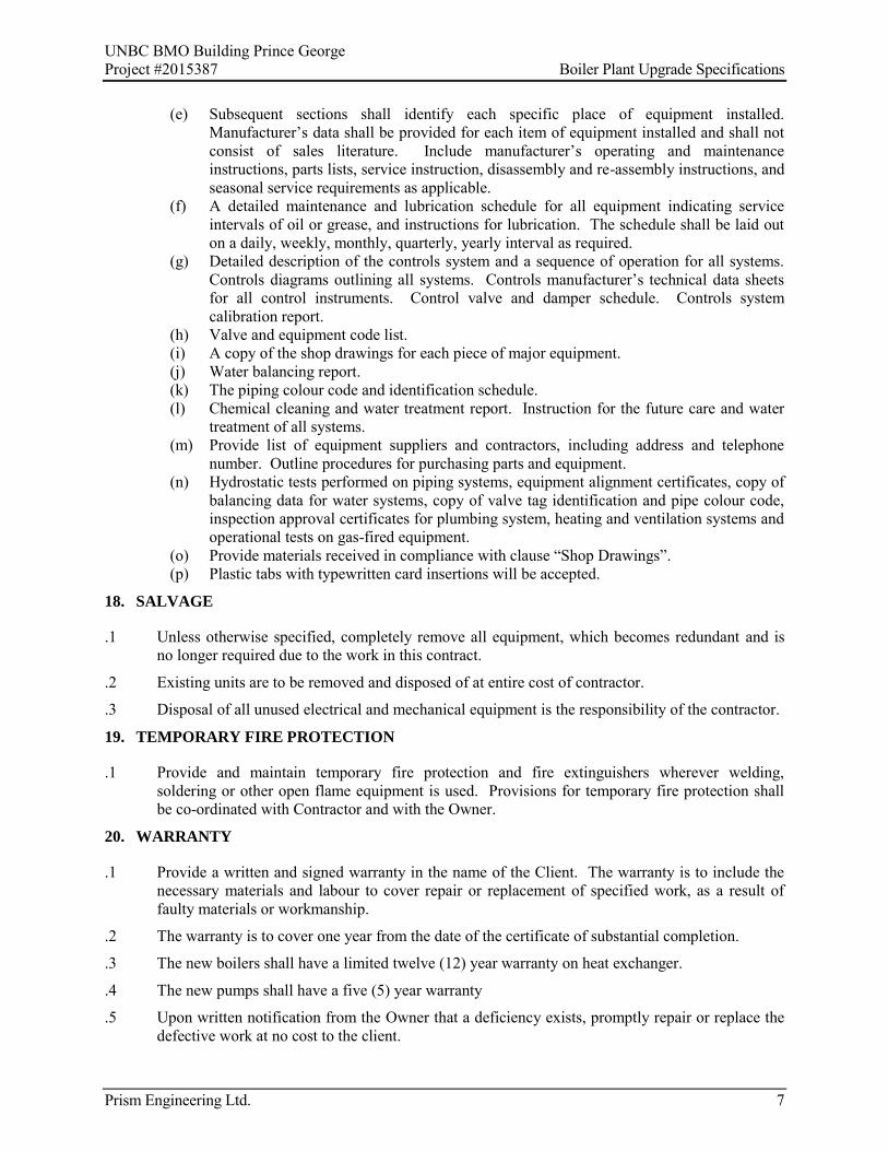
UNBC BMO Building Prince George Project #2015387 Boiler Plant Upgrade Specifications
Prism Engineering Ltd. 7
(e) Subsequent sections shall identify each specific place of equipment installed. Manufacturer’s data shall be provided for each item of equipment installed and shall not consist of sales literature. Include manufacturer’s operating and maintenance instructions, parts lists, service instruction, disassembly and re-assembly instructions, and seasonal service requirements as applicable.
(f) A detailed maintenance and lubrication schedule for all equipment indicating service intervals of oil or grease, and instructions for lubrication. The schedule shall be laid out on a daily, weekly, monthly, quarterly, yearly interval as required.
(g) Detailed description of the controls system and a sequence of operation for all systems. Controls diagrams outlining all systems. Controls manufacturer’s technical data sheets for all control instruments. Control valve and damper schedule. Controls system calibration report.
(h) Valve and equipment code list. (i) A copy of the shop drawings for each piece of major equipment. (j) Water balancing report. (k) The piping colour code and identification schedule. (l) Chemical cleaning and water treatment report. Instruction for the future care and water
treatment of all systems. (m) Provide list of equipment suppliers and contractors, including address and telephone
number. Outline procedures for purchasing parts and equipment. (n) Hydrostatic tests performed on piping systems, equipment alignment certificates, copy of
balancing data for water systems, copy of valve tag identification and pipe colour code, inspection approval certificates for plumbing system, heating and ventilation systems and operational tests on gas-fired equipment.
(o) Provide materials received in compliance with clause “Shop Drawings”. (p) Plastic tabs with typewritten card insertions will be accepted.
18. SALVAGE
.1 Unless otherwise specified, completely remove all equipment, which becomes redundant and is no longer required due to the work in this contract.
.2 Existing units are to be removed and disposed of at entire cost of contractor.
.3 Disposal of all unused electrical and mechanical equipment is the responsibility of the contractor.
19. TEMPORARY FIRE PROTECTION
.1 Provide and maintain temporary fire protection and fire extinguishers wherever welding, soldering or other open flame equipment is used. Provisions for temporary fire protection shall be co-ordinated with Contractor and with the Owner.
20. WARRANTY
.1 Provide a written and signed warranty in the name of the Client. The warranty is to include the necessary materials and labour to cover repair or replacement of specified work, as a result of faulty materials or workmanship.
.2 The warranty is to cover one year from the date of the certificate of substantial completion.
.3 The new boilers shall have a limited twelve (12) year warranty on heat exchanger.
.4 The new pumps shall have a five (5) year warranty
.5 Upon written notification from the Owner that a deficiency exists, promptly repair or replace the defective work at no cost to the client.

UNBC BMO Building Prince George Project #2015387 Boiler Plant Upgrade Specifications
Prism Engineering Ltd. 8
MECHANICAL SPECIFICATIONS
21. ACCEPTABLE AGENCIES AND CONTRACTORS
.1 The following is a list of contractors that are acceptable for this project.
.2 Any request for an alternative must be submitted during the time of tender complete with a list of past applicable projects and resumes of the field technicians that will be assigned to the project.
Operating and Maintenance Manuals Western Mechanical Services ( ) K. D. Engineering ( )
Mechanical Systems Balancing Western Mechanical Services ( ) K.D.Engineering ( )
Chemical Water Treatment Contractor used by UNBC ( )
22. BALANCING
.1 Scope of Work
.1 Adjust and balance the flow through the new boilers and the two new circulating pump and pumps.
.2 Measure flow values of the three boilers and two pumps using the circuit balancing valves.
.3 Procedures shall be in accordance with current edition of AABC’s National Standards for Field Measurement and Instrumentation, Total System Balance.
.2 Instruments
.1 Instruments for testing and balancing of hydronic systems shall have been calibrated within six months and verified for accuracy before start of work.
.3 General Procedures
.1 Permanently mark setting on valves.
.2 Take measurements to verify balance has not been disrupted or such disruption has been rectified.
.4 Balancing Report
.1 Submit draft copies of reports before final acceptance of project. Provide three copies of final report for inclusion in Operating and Maintenance Manuals.
.2 Include types, serial numbers and dates of calibration of instruments.
.3 Record test data on sepia from latest available revised set of mechanical drawings and submit three copies upon completion.
.4 Submit with report, pump curves with operating conditions plotted.
.5 Balancing Data
.1 Balance and equipment data shall be listed in Metric Units.
.2 Pump Design Data
Water flow rate Pressure
CES Engineering ( ) West Rocky Services ( )

UNBC BMO Building Prince George Project #2015387 Boiler Plant Upgrade Specifications
Prism Engineering Ltd. 9
Pump Motor full load current and measured current at full flow Pump Motor Rpm
.3 Pump Installation Data
Size Drive Type Motor type, Capacity, RPM, voltage, phase, cycles and full load motor amps
23. HYDRONIC SYSTEM CLEANING AND WATER TREATMENT
.1 Existing and New System Cleaning
.1 Prior to the installation of the new boilers into the hydronic system, the existing piping system with the existing boilers, shall be chemically cleaned and flushed.
.2 Cleaning shall be carried out to the recommendation of and under the direction of UNBC’s chemical cleaning and treatment agency.
.3 On completion of the system cleaning, all systems shall be flushed out with clean water until all traces of the cleaning chemical have been removed. All strainer baskets shall be removed, cleaned, and replaced.
.4 Flushing shall be done by opening a drain valve and allowing the makeup water system for the heating plant to supply makeup water until the effluent from the drain valve is clean. This will prevent air pockets occurring in the piping system during the cleaning process.
.2 Piping System Chemical Treatment
.1 After cleaning and flushing, the chemical cleaning agency shall treat the system water with a closed system inhibitor in the recommended quantities.
.2 A letter signed by a principal of the cleaning agency, certifying the cleaning of the system and the final chemical treatment shall be filed with the engineer for approval. This shall include a chemical analysis of the final system water condition.
.3 Chemical Pot Feeder and Side Stream Filter
.4 Retain the existing chemical pot feeder and side stream filter. Provide a box of 12 filter cartridges for the existing filter housing.
24. NAMEPLATES, LABELLING AND IDENTIFICATION
.1 All mechanical equipment, control equipment, instruments, control valves, main valves, pumps, fans, boilers, equipment, etc., shall be labelled, numbered, and indexed. Labels and tags shall be lamicoid plates, white writing on black background. The size and location of labels and tags and the size of lettering shall suit the area and installation and shall be as directed by UNBC. Valve tags shall be minimum 1-1/2 inch diameter. Tags and labels shall be secured on or adjacent to equipment. Valve and instrument tags shall be secured to the equipment with brass chains.
.2 All new and existing piping systems in the mechanical rom shall be identified and colour coded. Arrows shall indicate the direction of flow. The colour code shall match existing. Colour coding shall be 2 inch wide bands of pressure sensitive colour code tape applied around the pipe with a 50% overlap. Identification legends and arrows shall be pressure sensitive tape and shall be secured with colour coded bands. Coding, identification, and arrows shall be applied to pipe at 20 foot intervals, at all access panels, and at all equipment. Colour coding tape, identification legends, and directional arrows shall be Brady, or approved.
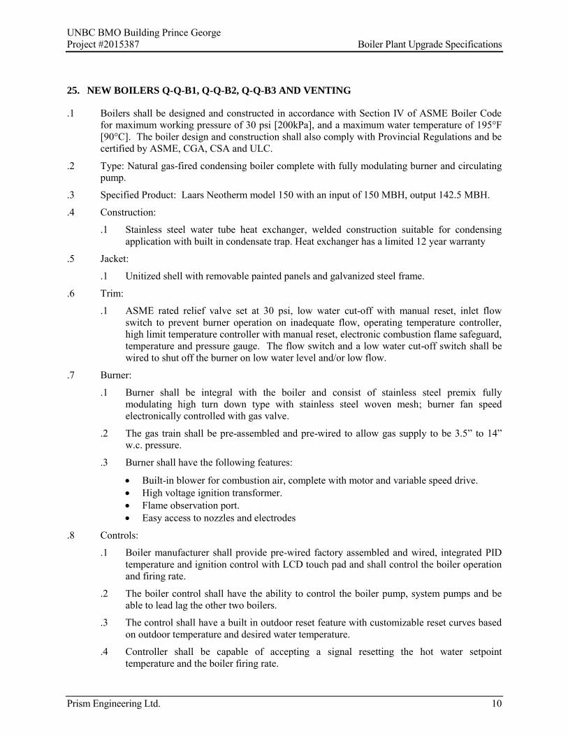
UNBC BMO Building Prince George Project #2015387 Boiler Plant Upgrade Specifications
Prism Engineering Ltd. 10
25. NEW BOILERS Q-Q-B1, Q-Q-B2, Q-Q-B3 AND VENTING
.1 Boilers shall be designed and constructed in accordance with Section IV of ASME Boiler Code for maximum working pressure of 30 psi [200kPa], and a maximum water temperature of 195°F [90°C]. The boiler design and construction shall also comply with Provincial Regulations and be certified by ASME, CGA, CSA and ULC.
.2 Type: Natural gas-fired condensing boiler complete with fully modulating burner and circulating pump.
.3 Specified Product: Laars Neotherm model 150 with an input of 150 MBH, output 142.5 MBH.
.4 Construction:
.1 Stainless steel water tube heat exchanger, welded construction suitable for condensing application with built in condensate trap. Heat exchanger has a limited 12 year warranty
.5 Jacket:
.1 Unitized shell with removable painted panels and galvanized steel frame.
.6 Trim:
.1 ASME rated relief valve set at 30 psi, low water cut-off with manual reset, inlet flow switch to prevent burner operation on inadequate flow, operating temperature controller, high limit temperature controller with manual reset, electronic combustion flame safeguard, temperature and pressure gauge. The flow switch and a low water cut-off switch shall be wired to shut off the burner on low water level and/or low flow.
.7 Burner:
.1 Burner shall be integral with the boiler and consist of stainless steel premix fully modulating high turn down type with stainless steel woven mesh; burner fan speed electronically controlled with gas valve.
.2 The gas train shall be pre-assembled and pre-wired to allow gas supply to be 3.5” to 14” w.c. pressure.
.3 Burner shall have the following features:
Built-in blower for combustion air, complete with motor and variable speed drive. High voltage ignition transformer. Flame observation port. Easy access to nozzles and electrodes
.8 Controls:
.1 Boiler manufacturer shall provide pre-wired factory assembled and wired, integrated PID temperature and ignition control with LCD touch pad and shall control the boiler operation and firing rate.
.2 The boiler control shall have the ability to control the boiler pump, system pumps and be able to lead lag the other two boilers.
.3 The control shall have a built in outdoor reset feature with customizable reset curves based on outdoor temperature and desired water temperature.
.4 Controller shall be capable of accepting a signal resetting the hot water setpoint temperature and the boiler firing rate.

UNBC BMO Building Prince George Project #2015387 Boiler Plant Upgrade Specifications
Prism Engineering Ltd. 11
.5 The boilers and their integral pumps and the distribution pumps shall be enabled when the outside temperature falls below 18°C, (adjustable).
.6 The existing Tekmar controller for the existing boilers to be reused to control the new boilers and pumps.
.9 Venting System:
.1 Type AL29-4C single wall stainless steel positive pressure sealed gas vent equivalent to existing stainless steel venting for the existing boilers.
.2 Reuse existing venting in the boiler room where possible to connect to the new boilers.
.3 The existing venting up the chimney shall be retained.
.4 The existing condensate drains for the venting shall be routed to the new acid neutralizer.
.10 Accessories:
.1 Provide field installed acid neutralizer for condensate discharge from boiler and boiler flues. The acid neutralizer shall have a capacity 2Kg of calcium carbonate installed in a plastic container. Condensate from the three boilers and the three flues shall be connected to the new acid neutralizer which is piped to the existing floor drain.
.2 Temperature and pressure gauge on supply piping connection on boiler.
.3 Seismic kit, with design certified by a professional engineer registered in the province of BC.
.4 Integral circulating pump installed on the supply outlet of the boiler.
.5 Factory trained personnel start-up. Provide a start-up report and combustion efficiencies report at 50% and 100% firing rate for each boiler.
.11 Commissioning:
.1 Manufacturer's agent and the mechanical contractor’s control technician shall:
Certify installation. Start up and commission installation. Carry out on-site performance verification tests including hot water reset with outside
temperature. Demonstrate operation and maintenance to the Owner and Consultant.
.12 Electrical:
.1 Electrical requirements: 120V/1/60 power supply, 20 amp circuit. Connect power supplies for the three new boilers and integral boiler pumps to existing power supplies for existing three boilers.
.13 Main gas train:
.1 To building code and provincial regulations including shut-off valve, pressure regulator, motorized electric shut-off valve, downstream block-test valve with test connection and pressure gauge.
.14 Extend existing gas piping from the three existing boilers to the gas connections on the three new boilers.

UNBC BMO Building Prince George Project #2015387 Boiler Plant Upgrade Specifications
Prism Engineering Ltd. 12
26. PIPING AND VALVES
.1 Piping shall be steel to ASTM A53 Grade B Schedule 40. Joints 75 mm and above shall be welded, joints 65 mm and smaller shall be screwed type. Fittings pressure class 125 to ASTMA536.
.2 Isolating valves 3”, (75 mm), and smaller shall be bronze or stainless steel ball valves with screwed ends.
.3 Circuit balancing valves shall be Armstrong model CBV sized for the flow as noted in the table on the drawings, flanged type, pressure class 125 psi.
.4 Check valves shall be flanged, silent, spring loaded type for mounting in downflow vertical position, class 125 psi.
.5 Strainers shall be flanged, pressure class 125 psi, and fitted with a blow-off pipe and ball valve, nipple, and cap, full size of the strainer blow-off tapping. Strainer baskets shall be stainless steel or monel with perforations properly sized for the service to be performed.
.6 Install air vents at high points in the piping. Pipe air vent outlet to drain.
.7 Install drain at low points, ¾” ball valves wit hose end connection and cap’
.8 Install Armstrong or equal circuit balancing valve in the supply piping downstream of the two Pumps Q-Q-P1 and Q-Q-P2.
.9 Provide 3” diameter pressure gauges complete with snubbers across the two system pumps Q-Q-P1 and Q-Q-P2 complete with ¼” tubing connections and isolating valves.
.10 Provide 7” mercury thermometers in inlet and outlet piping connections to the two new boilers.
.11 Accessories:
.1 Pipe the relief valves from the three boilers to the floor drain.
.2 Retain the existing makeup water assembly for the three boilers.
.3 Retain the existing expansion tank.
27. PIPING INSULATION
.1 Supply and install thermal piping insulation for the new hot water heating piping.
.2 Carry out repairs to thermal insulation at connections to existing piping systems.
.3 All insulation shall be applied over a clean, dry surface only after all pressure testing has been carried out and reviewed by the Engineer. All insulation shall be continuous and cover all pipe fittings, valves, joints and appurtenances.
.4 Insulation thickness, using an insulation K-factor of .24 at 75°F (24°C) shall be not less than:
Pipe Size Larger than
1/2” to 3” 3” Hot Water Heating 1” 1-1/2”
.5 Hot water heating pipes and fittings shall be insulated with fibreglass insulation with ASJ jacket. Insulation joints shall be butted tightly. All fittings up to 2” (50 mm) shall be insulated with mitre-cut pieces of insulation and pressure-sensitive, colour-matching tape. All fittings 2” (50 mm) and larger, including elbows, tees, valves, flanges and mechanical couplings, shall have pre-moulded PVC insulation fitting covers.

UNBC BMO Building Prince George Project #2015387 Boiler Plant Upgrade Specifications
Prism Engineering Ltd. 13
.6 All fittings 2” (50 mm) and larger, including elbows, tees, valves, flanges and mechanical couplings shall have pre-moulded PVC insulating fitting covers applied strictly in accordance with manufacturers recommendations. Hangers shall be outside the insulation and non-compressible insulation inserts (J-M thermo-12 or foam glass shall be used to extend 1” [25 mm] beyond the metal shields.)
.7 Metal shields between hangers and pipe insulation shall be made of galvanized metal.
.8 All exposed insulated piping and fittings shall be finished with PVC jacket of 0.015 gauge. The jacket shall be hot rolled and have self-seal laps. All seams shall be fused PVC end caps for piping above 1-1/2” (40 mm) or less. Joints for pipe fitting connections shall be sealed with silicone sealant, so that the complete installation maintains a continuous unbroken vapour seal.
.9 All hanger rods protruding through insulation shall have insulation tape applied around the rod opening in the insulation and at least 1” (25 mm) up the hanger rod. Where insulation has been notched for hangers, the notch shall be filled with insulation cement and sealed around and up the hanger 1” (25 mm) with insulation tape.
28. HANGERS & SUPPORTS
.1 Provide hangers or other approved supports at intervals as indicated below, both in horizontal and vertical runs.
.2 All new and existing piping in the boiler room shall be supported using seismic restraints and sway bracing as outlined in the C.A.L. S.M.A.C.N.A./P.P.I.C. Standard Manual. Refer to this Manual for full details. See also Sections 15200 and 15201.
.3 Piping shall be suspended from hangers using carbon steel threaded hanger rods attached to concrete inserts, or from beam clamps or from bolted brackets.
.4 All hangers shall be adjustable type. Strap hangers shall not be permitted.
.5 Where a clevis hanger is used, provide securing nuts above and below clevis strap.
.6 Locate hangers at not more than 600mm (24”) from each change of direction of horizontal piping, all valves, and branch connections. Vertical risers and stacks shall be supported with riser clamps at each floor.
Hanger spacing - not greater than the following: Piping 9.5mm to 12mm (3/8” to ½) 1800mm (6ft.) on centres Piping 20mm to 30mm (¾” to 1¼”) 2500mm (8ft.) on centres Piping 40mm to 65mm (1½” to 2½”) 2500mm (8ft.) on centres Hanger rods - to have machine threads in accordance with the following schedule: Piping 12mm to 50mm (½” to 2”) 9.5mm (3/8”) rod Piping 65mm to 90mm (2½” to 3”) 12mm (½”) rod For copper piping the hanger spacing shall not be greater than the following: Piping 9.5mm to 25mm (3/8” to 1”) 1500mm (5ft.) on centres Piping 30mm (1¼”) and larger 3000mm (10ft.) on centres
29. NATURAL GAS PIPING
.1 Natural gas piping shall be installed to CAN/CGA-B149.1 (current edition) and to Fortis BC standard.

UNBC BMO Building Prince George Project #2015387 Boiler Plant Upgrade Specifications
Prism Engineering Ltd. 14
.2 Interior gas service - screw or weld up to 50 mm (2”), weld 65 mm (2½”) and larger.
.3 All branch connections, except those less than half diameter of main shall be made with welding tees.
.4 Equipment Connections
.1 Install unions or flanges in connections to all equipment and specialty components.
.2 Arrange piping connections to allow ease of access and for removal of equipment.
.3 Align and independently support piping connections to prevent piping stresses being transferred to equipment.
.5 Piping Tests
.1 In accordance with the National Standard of Canada “Natural Gas Installation Code” CAN/CGA-B149.1-M86.
.6 Valves
.1 Provincial Gas Department approved and suitable for temperature to which they are exposed. Acceptable products: Homestead 6012, Emco, Mueller, Newman-Milliken, Wallaceburg, Rockwell.
.7 Remove existing gas piping from the existing shut off valve to the existing boilers.
.8 Extend new piping from shutoff valve to the new boilers.
30. THERMOMETERS AND PRESSURE GAUGES
.1 Provide wells for thermometers at the inlet and outlet of each boiler, and three way valve. Acceptable: Trerice, Marsh.
.2 Provide tapings in the piping and pressure gauges with 3" min. diameter dials on suction and discharge of pumps.
31. CIRCULATING PUMPS (Q-Q-P1, Q-Q-P2)
.1 Circulating pumps Q-Q-P1, Q-Q-P2, shall be Grundfos Magna 3 wet rotor type pumps, with integral variable speed drive. Size, type and capacity as scheduled.
.2 Electrical Requirements: 120/1/60, 15 amp circuit.
.3 The pumps shall have a cast iron body with permanent split magnet rotor and shall have integrated variable speed drives with built in pressure control to vary the speed.
.4 Circulating pumps shall be nominal 1750 rpm. Pump impeller curves shall not cross the pump H.P. curve for the specified flow and head. Where this occurs, the motor H.P. shall be increased to suit. Pump motor sizes specified are minimum acceptable.
.5 Furnish and install 6 mm (1/4") gauge tappings on the suction and discharge side of each pump. Each gauge tapping shall be fitted with a 1/4" needle valve, Winter DH-11, or equal, with nipple and cap. See Section - Gauges and Thermometers.
.6 Use the existing power supplied for the existing pumps to power the new pumps.
.7 Start up the pumps and set the pressure control for constant pressure.
32. TESTING, COMMISSIONING AND INSTRUCTION TO THE OWNER
.1 New Boilers Q-Q-B1, Q-Q-B2 and Q-Q-B3
Boilers and integral circulators installed and operational,

UNBC BMO Building Prince George Project #2015387 Boiler Plant Upgrade Specifications
Prism Engineering Ltd. 15
Piping installation complete including PRVs piped to drain, Existing piping system cleaned along with new boilers and new piping systems, Safety controls installed and operational, Boiler controls complete and operational, Boilers wired to existing Tekmar control system and operational, Boilers emergency shutoff switch installed and operational, Boilers started up by manufacturer’s agent and boiler efficiency tests made, Sequence of operation of boilers through boiler and Tekmar controller to demonstrate
automatic boiler sequencing and output adjustment.
.2 Heating Distribution Pumps, Q-Q-P1, Q-Q-P2,
Pumps installed and operational, Controls for pumps operational, Controls sequences operational,
.
33. EQUIPMENT SCHEDULES
.1 The following equipment schedules are to be read in conjunction with the pertinent sections of the specification. The specification sections and the schedules are complimentary to one another.
.2 The equipment make and size shown in the schedules is that which the project design and drawings are based on and for which space in the building design has been allocated.
.3 Where alternative equipment makes have been shown in the specification equipment sections, the Mechanical Approval List, or are approved during the tender process, it shall be the contractors and equipment suppliers responsibility to assure that the alternate equipment meets all the requirements of the specification, is of adequate size and capacity, has similar electrical characteristics, is suitable for the duty intended, and is of a physical size and shape to fit into the space which has been allocated in the system design. Where any alternate equipment fails to meet any of the criteria for the use of alternate equipment spelled out in this specification, it shall be rejected for use in the project.
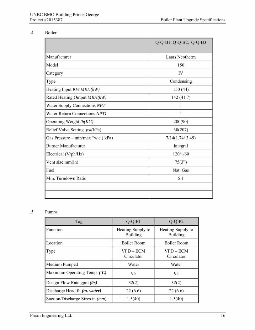
UNBC BMO Building Prince George Project #2015387 Boiler Plant Upgrade Specifications
Prism Engineering Ltd. 16
.4 Boiler
Q-Q-B1, Q-Q-B2, Q-Q-B3
Manufacturer Laars Neotherm
Model 150
Category IV
Type Condensing
Heating Input KW MBH(kW) 150 (44)
Rated Heating Output MBH(kW) 142 (41.7)
Water Supply Connections NPT 1
Water Return Connections NPT) 1
Operating Weight lb(KG) 200(90)
Relief Valve Setting psi(kPa) 30(207)
Gas Pressure – min/max “w.c.( kPa) 7/14(1.74/ 3.49)
Burner Manufacturer Integral
Electrical (V/ph/Hz) 120/1/60
Vent size mm(in) 75(3”)
Fuel Nat. Gas
Min. Turndown Ratio 5:1
.5 Pumps
Tag Q-Q-P1 Q-Q-P2
Function Heating Supply to Building
Heating Supply to Building
Location Boiler Room Boiler Room
Type VFD – ECM Circulator
VFD – ECM Circulator
Medium Pumped Water Water
Maximum Operating Temp. (ºC) 95 95
Design Flow Rate gpm (l/s) 32(2) 32(2)
Discharge Head ft. (m. water) 22 (6.6) 22 (6.6)
Suction/Discharge Sizes in.(mm) 1.5(40) 1.5(40)

UNBC BMO Building Prince George Project #2015387 Boiler Plant Upgrade Specifications
Prism Engineering Ltd. 17
Motor Power W 276 276
Motor Amps A 2.5 2.5
Power Supply (V/ph/Hz) 120/1/60 120/1/60
Manufacturer Grundfos Grundfos
Model and size Magna 3 40-80F Magna 3 40-80F
Notes 1,2,3 1,2,3
.1 Variable speed drive
.2 ECM motor
.3 companion flanges

UNBC BMO Building Prince George Project #2015387 Boiler Plant Upgrade Specifications
Prism Engineering Ltd. 18
34. BUILDING CONTROLS
.1 Reuse the existing Tekmar controller and the controllers on the boilers to control the operation of the three new boilers and two heating circulating pumps.
.2 Provide a new outdoor temperaturesensor in the location of the existing outdoor temperature sensor to provide input for the hot water temperature reset function.
.3 The three new boilers, their integral circulating pumps and the two new heating distribution pumps shall be enabled if the outside temperature falls below 18°C.
.4 The operation of the boilers shall be alternated on a bi weekly basis.
.5 The Tekmar controller in conjunction with the boiler controllers shall fire the boilers, operate the boiler pumps and system circulating pumps to maintain the boiler water supply temperature in accordance with the reset schedule based on outside temperature.
The secondary loop supply water temperature shall be to an inverse linear reset schedule with outdoor air temperature (OAT) as follows:
o OAT o Boiler Outlet - Temp
o -34°C (-30° F) 90C (194 F)
o 16°C (61 F) 45C (110 F)
.6 The system circulating pumps operate on a lead lag basis. If one pump fails, the second pump shall start. The pumps shall be alternated on a bi-weekly basis.
ELECTRICAL SPECIFICATIONS
35. GENERAL, ELECTRIC SPECIFICATIONS
.1 All electrical Work shall be completed to building Owner’s requirements.
.2 The word “provide” shall mean to “supply and install” unless otherwise indicated.
.3 Provide labour, materials, miscellaneous services, equipment identification by means of lamicoid nameplates, testing and balancing and any other items necessary to complete the Work as shown and specified. Include all items necessary to comply with latest edition of electrical and building codes, by-laws and authorities having jurisdiction and necessary for complete and operating electrical systems.
.4 Work shall be performed in an acceptable manner by skilled tradesman. Any unsatisfactory workmanship shall be replaced to the satisfaction of the owner.
.5 Obtain and pay for all permits and inspections, and after completion of Work and acceptance, provide certificates to the Owner, verifying that the Work conforms to the requirements of all codes and authorities having jurisdiction.
.6 Provide the Owner with a written warranty, effective for one year, after date of acceptance, for the complete installation. Repair and/or replace any defects arising during this period at no extra cost to the Owner.

UNBC BMO Building Prince George Project #2015387 Boiler Plant Upgrade Specifications
Prism Engineering Ltd. 19
36. SCOPE OF WORK
.1 Disconnect the electrical services to existing boilers B-1, B-2, B-3- and pumps P-1 and P-2;
.2 Remove provide electrical services for the three new boilers Q-Q-B1, Q-Q-B2, Q-Q-B3 their integral circulators and two new heating pumps Q-Q-P1, Q-Q-P2;
.3 Provide an emergency shut off switch at the door to the boiler room to shut off the three new boilers;
.4 Label new devices as per Owner’s standard and install new circuit identification list in panels;
.5 Provide warranty and documentation as described elsewhere in the specifications.
37. SITE EXAMINATION
.1 Carefully examine the site and conditions of the proposed Work together with the Work of all other trades and include in the tender price all costs for Work such as cutting and patching, rerouting and repositioning of electrical equipment and wiring, made necessary to accommodate any architectural renovations and electrical systems shown.
.2 Cutting and patching for new and existing building systems to accommodate the Work of this trade shall be done by workmen skilled in the appropriate trades.
38. PROTECTION OF WORK AND CO-ORDINATION WITH OTHER TRADES
.1 Protect Work of this and other trades, existing finishes, systems and services which must remain in operation. Replace and/or reinstall any existing services which are to remain that are improperly installed or create any interference with new construction.
.2 Schedule and co-ordinate all Work with other trades before installation of equipment to avoid conflict during or after installation.
39. DEMOLITION
.1 Include in the tender price for the removal and re-installation of wiring devices and equipment made necessary due to the renovations and/or installation of new equipment. Cut back and cap unused raceways and outlets and remove unused wiring back to panel board in an approved manner to a concealed location so that the finished Work appears neat and clean.
40. CLEAN UP
.1 Remove and clean up any debris or material from the site throughout the duration of the contract and on completion of the Work as directed by Owner’s Representative.
41. WIRING METHODS
.1 All wiring shall be colour coded copper min. #12 AWG RW-90 X-link unless otherwise specified. Wire shall be run concealed in EMT conduit. Flexible conduit or TECK 90 CU cable shall be limited to a maximum of 6 feet where connected to vibrating equipment unless prohibited by code or otherwise noted.
42. WIRING DEVICES
.1 All wiring, devices, and equipment shall be new and CSA or suitably approved unless otherwise noted. Obtain Warnock Hersey or local electrical inspection authority approval for any specified non-CSA electrical equipment. Equipment of same type shall be of same manufacturer.
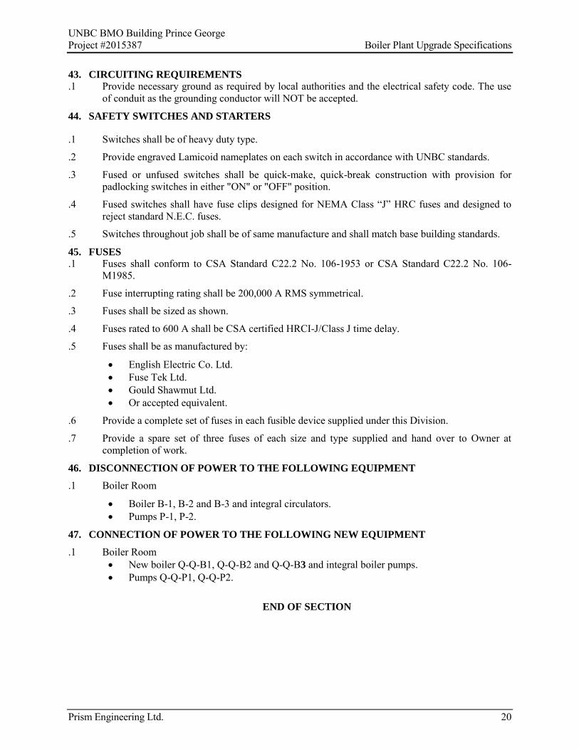
UNBC BMO Building Prince George Project #2015387 Boiler Plant Upgrade Specifications
Prism Engineering Ltd. 20
43. CIRCUITING REQUIREMENTS
.1 Provide necessary ground as required by local authorities and the electrical safety code. The use of conduit as the grounding conductor will NOT be accepted.
44. SAFETY SWITCHES AND STARTERS
.1 Switches shall be of heavy duty type.
.2 Provide engraved Lamicoid nameplates on each switch in accordance with UNBC standards.
.3 Fused or unfused switches shall be quick-make, quick-break construction with provision for padlocking switches in either "ON" or "OFF" position.
.4 Fused switches shall have fuse clips designed for NEMA Class “J” HRC fuses and designed to reject standard N.E.C. fuses.
.5 Switches throughout job shall be of same manufacture and shall match base building standards.
45. FUSES
.1 Fuses shall conform to CSA Standard C22.2 No. 106-1953 or CSA Standard C22.2 No. 106-M1985.
.2 Fuse interrupting rating shall be 200,000 A RMS symmetrical.
.3 Fuses shall be sized as shown.
.4 Fuses rated to 600 A shall be CSA certified HRCI-J/Class J time delay.
.5 Fuses shall be as manufactured by:
English Electric Co. Ltd. Fuse Tek Ltd. Gould Shawmut Ltd. Or accepted equivalent.
.6 Provide a complete set of fuses in each fusible device supplied under this Division.
.7 Provide a spare set of three fuses of each size and type supplied and hand over to Owner at completion of work.
46. DISCONNECTION OF POWER TO THE FOLLOWING EQUIPMENT
.1 Boiler Room
Boiler B-1, B-2 and B-3 and integral circulators. Pumps P-1, P-2.
47. CONNECTION OF POWER TO THE FOLLOWING NEW EQUIPMENT
.1 Boiler Room New boiler Q-Q-B1, Q-Q-B2 and Q-Q-B3 and integral boiler pumps. Pumps Q-Q-P1, Q-Q-P2.
END OF SECTION