Embed Size (px)
Citation preview

University of Huddersfield Repository
Ali, Jafar, Fieldhouse, John D., Talbot, Chris J. and Mishra, Rakesh
Thermal discharge of warm water into cooler stagnant water
Original Citation
Ali, Jafar, Fieldhouse, John D., Talbot, Chris J. and Mishra, Rakesh (2009) Thermal discharge of warm water into cooler stagnant water. In: What Where When: Multidimensional Advances for Industrial Process Monitoring. Proceedings. University of Leeds, Leeds, pp. 227238.
This version is available at http://eprints.hud.ac.uk/id/eprint/8230/
The University Repository is a digital collection of the research output of theUniversity, available on Open Access. Copyright and Moral Rights for the itemson this site are retained by the individual author and/or other copyright owners.Users may access full items free of charge; copies of full text items generallycan be reproduced, displayed or performed and given to third parties in anyformat or medium for personal research or study, educational or notforprofitpurposes without prior permission or charge, provided:
• The authors, title and full bibliographic details is credited in any copy;• A hyperlink and/or URL is included for the original metadata page; and• The content is not changed in any way.
For more information, including our policy and submission procedure, pleasecontact the Repository Team at: [email protected].
http://eprints.hud.ac.uk/

University of Huddersfield Repository
Ali, Jafar, Fieldhouse, John D., Talbot, Chris J. and Mishra, Rakesh
Thermal discharge of warm water into cooler stagnant water
Original Citation
Ali, Jafar, Fieldhouse, John D., Talbot, Chris J. and Mishra, Rakesh Thermal discharge of warm water into cooler stagnant water. In: What Where When Multi-dimensional Advances for Industrial Process Monitoring, 23 - 24, June, 2009, University of Leeds, Leeds, UK. (Unpublished)
This version is available at http://eprints.hud.ac.uk/9893/
The University Repository is a digital collection of the research output of theUniversity, available on Open Access. Copyright and Moral Rights for the itemson this site are retained by the individual author and/or other copyright owners.Users may access full items free of charge; copies of full text items generallycan be reproduced, displayed or performed and given to third parties in anyformat or medium for personal research or study, educational or not-for-profitpurposes without prior permission or charge, provided:
• The authors, title and full bibliographic details is credited in any copy;• A hyperlink and/or URL is included for the original metadata page; and• The content is not changed in any way.
For more information, including our policy and submission procedure, pleasecontact the Repository Team at: [email protected].
http://eprints.hud.ac.uk/

What Where When Multi-dimensional Advances for Industrial Process Monitoring.
Leeds, UK, 23 – 24 June 2009
227
Thermal discharge of warm water into cooler stagnant water
Jafar Ali, John Fieldhouse, Chris Talbot and Rakesh Mishra
University of Huddersfield, Queensgate, Huddersfield, HD1 3DH, United Kingdom
[email protected], [email protected]
Abstract
This paper is concerned with development of a predictive tool to determine the heat diffusion
profile for heated water discharge into a body of stagnant receiving water. The process makes
use of a thermal imaging camera to measure the discharge plume from a range of sites in
order to observe the actual discharge and then to provide a mathematical model that will
allow British Waterways to satisfy the Environmental Agency regulations. In addition the
sites are replicated in a laboratory environment with a scale model tank that allows the
mixing zones to be measured under variable conditions. In this case the heated water is dyed
to provide a visual plume in addition to the thermal image. The plume and mixing zone are
then predicted using appropriate software such as Matlab, the model being optimised to
reflect the real measured discharges.
1. Introduction
The disposal of heated water from power plants and cooling systems into natural
water environment is one of the major environmental problems. Water is normally withdrawn from natural or artificial sources to the cooling system heat exchanger, the
cooling water increases in temperature within the system then it’s discharged back
into the lakes, rivers or canals resulting in a rise in the bulk temperature of the surrounding water. The main effect of the increased in ambient water temperature is
the reduction of the dissolved oxygen which might put fish life and other aquatic life-
form at risk. The increase in temperature also affects on the balance of the natural and biological process in the water. There are large number of studies of this type
regarding water mixing, heated water discharge into a cooler water, the majority of
them are based on assumptions, some use experimental model tanks but do not validate with real field trials whereas others only make use of mathematical models
and again do not validate with field trials. In this paper a study of heated water
discharge into stagnant water is described using a new technique. A thermal camera is used to measure the heat diffusion profile on the surface of the receiving water using
a number of British Waterways canal sites. The sites are then replicated in a
laboratory environment using a scale model tank. The combined results are then used to develop a two dimensional mathematical model for subsequent discharge
evaluation. In addition Matlab software is used to develop the model towards a three
dimensional representation showing the distribution of heat through out the canal. This is carried out using variable values of heat diffusion coefficients. This work is
currently limited to the study of heated water discharge into the body of stagnant
(stationary) receiving water. The majority of work in this paper concentrates on the initial process – that of determining the heat diffusion profile and plume shape on the

228
surface of the receiving water. At the moment the University of Huddersfield have 3 sites licensed to extract water for cooling purposes. All these sites have
comprehensive records and all show that the process is safe for aquatic life. British
Waterways’ one dimensional mathematical model suggests they will not be safe and if the model is over-conservative in its prediction then British Waterways may be
rejecting licensing applications that are in reality safe. It is this situation that demands
a more realistic prediction tool be developed; a tool that is readily understood, adequate for the level of the applications and easily manipulated to represent the
varied situations that are likely to be experienced.
2. Field Trial
The Central Services Building at University of Huddersfield was selected as the
primary site for initial investigations as thermal plume of the flow occurs below a
bridge and so is clearly defined. This is shown in Figure 1. The University has a licence from British Waterways to use the CSB site as part of the building cooling
system. As such the University is allowed to extract cold water from the canal and
discharge warm water into it.
By law the maximum temperature of canal ambient should not exceed 28˚C, the
reason being that the water begins to de-oxygenate and so the health of aquatic life is
put at risk. As a result of such regulations the University of Huddersfield have to maintain a complete record of extraction volumes, inlet temperatures, discharge
temperatures and surrounding environmental parameters.
a) Bridge over discharge pipe b) Discharge pipe with beam showing grid graduations.
Figure 1: View of Central Services Site
To monitor the whole site it was necessary to establish a reference grid over which the results of water flow and temperature would be measured across, along and below
the surface of the canal. The centreline of the outlet pipe and the end position of the
pipe served as the zero position. A graduated pole was laid along the banking to give the linear reference points and a second pole was fixed at 90° to the banking to give
Discharge
pipe
Plume
229
the transverse reference positions. A third vertical pole was secured to the main pole to which the thermocouple probe and flow meter could be attached. This third pole
was also graduated to indicate depth. The arrangement is generally as shown in
Figure 1(b). Ambient canal water temperatures were recorded 15m upstream and downstream of the outlet discharge point. Both the ambient canal water and air
temperatures were recorded with the use of ‘k’ type thermocouples with digital meter
at the start and end of the trial. The canal water temperature was then measured and recorded at the grid points at depths: the surface, at mid depth and 50mm above the
bed.
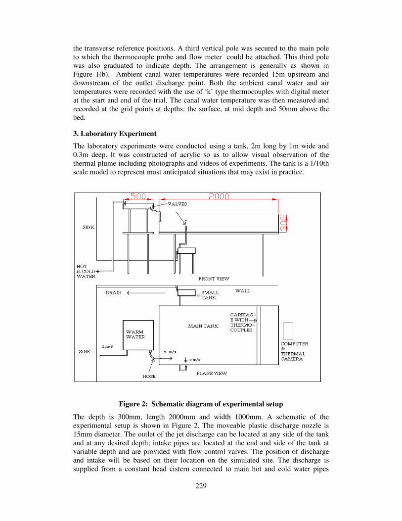
3. Laboratory Experiment
The laboratory experiments were conducted using a tank, 2m long by 1m wide and
0.3m deep. It was constructed of acrylic so as to allow visual observation of the
thermal plume including photographs and videos of experiments. The tank is a 1/10th scale model to represent most anticipated situations that may exist in practice.
Figure 2: Schematic diagram of experimental setup
The depth is 300mm, length 2000mm and width 1000mm. A schematic of the experimental setup is shown in Figure 2. The moveable plastic discharge nozzle is
15mm diameter. The outlet of the jet discharge can be located at any side of the tank
and at any desired depth; intake pipes are located at the end and side of the tank at variable depth and are provided with flow control valves. The position of discharge
and intake will be based on their location on the simulated site. The discharge is
supplied from a constant head cistern connected to main hot and cold water pipes

230
with flow control valves to maintain the required temperature, discharge speed is controlled by a valve, a by-pass line was installed to allow preliminary adjustment of
temperature and flow before water was discharged into the tank. Intake water returns
to a small tank where the temperature and flow are measured then extracted to drainage.
4. Thermal Camera:
The method employed in this study to observe the heat distribution on surface of the canal is to use a Thermal Camera. The thermal camera shows the heat diffusion on
the surface of a hot body by transforming an infrared image coming of a hot body into
radiometric so translating the data into a coloured image which is representative of the thermal gradients across the body. The image may be observed on a LCD monitor
and stored for future analysis and interrogation. A typical thermal image and normal
colour image is shown in Figure 3. It is necessary to set the camera to a right emissivity (the capacity of a surface to emit heat, at a given temperature) which for
water is 0.96. To avoid unnecessary and unwanted reflections it is necessary to ensure
the thermal camera is placed in a position that is directed to the test body without the
effects of reflection - which is the most problematic issue facing the thermographer -
especially with thermal water studies
Figure 3 shows the thermal and digital image for discharge water from the Central Service Building at the University of Huddersfield into Huddersfield Broad Canal.
Figure 4 shows images of the laboratory tank and a typical discharge plume into the
tank. Note how the camera records the hot pipe leading to the nozzle
Discharge pipe Discharge pipe
a. Thermal image b. Digital image
Figure 3: Thermal and digital image of plume from downstream CSB site
Thermocouple
Heated
plume

231
Figure 5: Heat diffusion (submerged discharge) on surface of Birmingham canal
BBC Mailbox site
It is difficult to use the thermal camera for submerged discharge studies because of reflection issues.
Figures 5 and 6 show such a recording from a submerged discharge but the plume
effect is not observed until the warm water rises to the surface. To complete the study it is necessary to determine the heat diffusion profile below the surface to the bed of
the canal using a temperature probe. It is for that reason that a mathematical model
has to be developed.
10.0°C
35.0°C
SP01
SP05
SP07
SP11
SP15
SP17
SP20
a. Heat diffusion on surface of tank
b. Model tank
Figure 4: Thermal and digital image of model tank
Building reflection outline
Heated
plume edge
Plume
Mixing
zone
Thermocouple
Plume

232
Figure 6: Merged digital and thermal image shows reflection effects
5. Mathematical Model:
The domain in Figure 7 shows the flow directions, the axes and the diffusion
coefficient directions, which are involved in the mathematical model. The main
equation used is the advection diffusion equation as shown in Equation 1. The left hand side of the equation represents flow and the right hand side diffusion. To
produce the model it considered that the coefficient of heat diffusion is applied
accordingly to suit the characteristics in the lateral and vertical directions – that is across the flow and depth-wise. The flow in the third direction, along the x axis,
which is considered longitudinal downstream of the discharge, is velocity dependant.
Steady state condition is considered to be when the temperature does not change with time and is further downstream beyond the plume.
Where T is temperature, t is time, U, V, W velocity in x, y and z direction respectively, Dx, Dy, Dz are diffusion coefficients in x, y and z direction respectively.
Building
reflection
Heated plume
edge
)1( 2
2
2
2
2
2
Equationz
TDz
y
TDy
x
TDx
z
TW
y
TV
x
TU
t
T
∂
∂+
∂
∂+
∂
∂=
∂
∂+
∂
∂+
∂
∂+
∂
∂

233
Figure 7: Flow configuration, a. (sectional view), b. (plan view)
)2(
)2(
0
2
2
2
2
2
2
aEquationy
TDy
x
TU
Equationz
TDz
y
TDy
x
TU
t
T
∂
∂=
∂
∂
∂
∂+
∂
∂=
∂
∂
=∂
∂
Solution of the partial differential equation 2a (Crank, 1970) gives:
)3(/4
2
EquationUDx
y
e
U
x
AT
−
=
:),3( yieldstosubt
xUvelocity =

234
)4( 4
2
EquationDt
y
et
AT
−
=
At the discharge point of the jet the boundary conditions will be:
T=To at x=0 -b < y < b
T= Ta at x=0 -b > y > b
To, Ta are discharge and ambient temperature respectively.
If M is the total heat diffusion in canal with infinite length:
)5( EquationTdyM ∫∞
∞−
=
Sub A into Equation 4: is giving the spreading of an amount M of heat discharge at
x=0
)6( ..2
4
2
EquationetD
MT Dt
y−
=π
Equation 7 gives the heat diffusion on the surface of canal. For the diffusion towards
the bed equation7 becomes:
6. Diffusion Coefficient
When warm water discharges into stagnant receiving water, the warm water will
spread out in all three directions x, y and z. This occurs because of the random motion of molecules for the heated water – the process being called diffusion. The diffusion
coefficient is variable from one location to another even along the same canal. It
varies in all directions as its value is influenced by many parameters such as flow, cross section of canal, shape of bed, concentration of discharge and ambient
temperature. In fact its value is hard to predict and for that reason researchers
undertaking thermal discharge studies tend to avoid the use of this value. The diffusion coefficients used in these studies are 0.002m²/s, 0.00005m²/s in y and z
direction respectively and so the parameters p, p1 become 0.018m and 0.005m
respectively. By applying the developed equations in Matlab the heat diffusion profile on the surface will be as shown in Figures 8a and sectional profile as in Figures 9a
)7( ).2.2
)(2
(),( EquationTaxp
yberf
xp
yberf
TaToyxT +
++
−−=
)8( ).12.12
)(2
(),( EquationTaxp
zberf
xp
zberf
TaToyxT +
++
−−=

235
whereas Figures 8b and 9b show the heat diffusion profile for smaller values of p, p1 (diffusion coefficients).
Figure 8.a: Heat diffusion on surface of canal CSB site (plan view)
Figure 8.b: Heat diffusion for a smaller value of p. (plan view)
Figure 8 Heat Diffusion on surface for variable “p”.
Figure 9.a: Heat diffusion through the depth of canal CSB site (sectional view)
Figure 9.b: Heat diffusion for smaller value of p1. (sectional view)
Figure 9 Heat Diffusion with depth for variable “p”
7. Results and Discussion
Figure 3 shows the comparison of the discharge plume at the Central Services
Building (CSB) taken with a digital camera and the thermal imaging camera. The outlet pipe is semi-submerged and the mixing plume can be clearly seen on the canal
surface. The images clearly show the extent of the plume downstream and to the sides
but what is not evident from the thermal images is the three dimensional effect of the plume and how the temperature dissipates through the depth of the canal. The
centreline temperature measurements by thermocouples on the site trial, along with
the experimental data, are compared to the centreline temperature measured by the thermal camera and the data obtained by the mathematical model. The results are

236
shown in Figures 10a&b where it is seen that the general form of the graphs are similar.
Figure 10.a: Centreline temperature decay
Figure 10.b: Centreline temperature decay
The temperature distribution on the surface and through canal depth which was
obtained by the mathematical model (and then applied in Matlab) is illustrated in
Figures 8 and 9. What can be seen also from the Matlab results (figures 8.b and 9.b) are the effects of parameter p (diffusion coefficient/ discharge velocity) on the shape
of plume, with higher value of p resulting in wider plume and mixing zone and vice
versa.

237
8. Conclusion
This paper presented a new technique in the studies of thermal discharge and heat
diffusion profile prediction. The technique makes use of a Thermal Camera to
observe the heat distribution on the surface of receiving water and the extent of the mixing zone and as such the heated areas can be clearly identified by the thermal
images. Mathematical models have been developed and compared to the temperature
measurements on a selected canal site as well as the results obtained from the laboratory experiments using the 1/10th canal simulation model. The initial Matlab
results compare favourably with the site and laboratory results and also identified the
effects of heat diffusion coefficient on the width of plume – that is a larger plume is observed for high diffusion coefficient discharge.
9. References
Ali, J. and Poxton, A. (2006) ‘Study of warm water discharge into British Waterways canal’ M.Sc.
dissertation, University of Huddersfield.
Crank, J. (1970) ‘The Mathematics of Diffusion’ Oxford.19 853307 1
Coulson, J.M. & Richardson, J.F.(2003)Chemical Engineering, vol.1, sixth edition, Butterworth
Heinemann, ISBN 0 7506 4444 3
10. Bibliography
Anwar, O. H. (1987) Flow of Surface Buoyant Jet in Cross Flow, Journal of Hydraulic Engineering,
Vol. 113, (7), pp. 892-904.
Ari, S., Nagao, M., Sakyo, H., Iwasaki, T. and Suizu, S. (1998) Spreading of Negatively Buoyant Jet
on the Bed Floor, Parallel Session( Parallel 22), Flow Experiment and basics
Environment Agency (1997) The Surface Water (Fishlife) (Clssification) Regulation,s No. 1331,
London.
Erduran, K. S., Kutija, V. (2003) ‘Quasi-three-dimensional numerical model for flow through flexible
rigid, submerged and non submerged vegetation, Journal of Hydroinformatics, 5, (3) pp. 189-202
Horikawa, K., Lin, M. and Sasaki, T. (1979) Mixing of Heated Water Discharged in the Surface Zone,
Proceeding of the Coastal Engineering, 3, pp. 2563-2583.
Kim, D. G., Seo, W. (2001) Modelling of the mixing of heated water discharged from a submerged
multiport diffuser, Journal of Hydraulic Research, 38, (4), pp. 259-269
Lee, J. H. (1980) Stability and Mixing of a Round Buoyant Discharge in Shallow Water, Second
International Symposium on stratified Flows, 2, pp.881-897
Lee, W. and Huai, W. (1995) Calculation of whole field for vertical round buoyant jets in static
linearly stratified environment, Journal of Hydraulic Research, 33, (6), pp. 865-876.
McGuirk, J. J. and Rodi, W. (1978) Mathematical modelling of three-dimensional heated surface jets,
Journal of Fluid Mechanics, 95, (4), pp. 609-633.
Moawad, A. K., Rajaratnam, N., Stanley, S. J. (2001) Mixing with multiple circular turbulent jets,
Journal of Hydraulic Research, 39, (2) pp. 163-168
Ozturk, H. Z., Sarikaya, A. F., Demir, I. (1995) a Simplified Model for Thermal Discharges, Water and
Science Technology 32,(2), pp. 183-191

238
Parr, A. D. and Sayre, W. W. (1979) Multiple Jets in Shallow Flowing Receiving Waters, Journal of
Hydraulic Division, 105, pp.1357-1374.
Qi, M., Chen, Z., Fu, R. (2001) Flow structure of the plane turbulent impinging jet in cross flow,
Journal of Hydraulic Research, 39, (2) pp.155-161
Seo, W., Yu, D., Kim, H. S. Near Field Mixing of Submerged Multiport Diffusers in Shallow Water
with Strong Currents, Seoul National University, Gwanak-Ku, Seoul, Korea
Seo, W., Kim, D. G., Shim, M. P. (1998) Velocity Structure of Wall Jet Discharging from Circular
Orifice, Water Quality in Rivers and Lakes, Parallel Session ( Parallel 42)
Sherwin, K., Horsley, (1996), M. Thermofluids, Chapman & Hall, ISBN 0 -412 59800 0
Sojisuporn, P. Application of Numerical Model to Thermal Plume Dispersion from Power Plant at
Kanom, the seventh OMISAR workshop on ocean models Faculty of Science, Chulalongkkorn
University, Bankok (10300) Thailand (undated).
Taylor, G. I. (1921) Diffusion by continues movements, Proceedings of London Mathematical Society,
series 2, 20, pp. 196-212.
Tsubono, T. et al. (2002) Improvement on the Computational Efficiency of the 3-Dimensional Warm
Water Diffusion Model, CRIEPI Rep. U01040 (in Japanese)
Ungate, D., Harleman, R. F. and Jirka, G. H. (1975) Stability and Mixing of Submerged Turbulent Jets
at Low Reynolds Number, Energy Laboratory Report. No. MIT-EL 75-014
Wallis, S. G. and Manson, J. R. (2004) Methods for predicting dispersion coefficients in rivers, Water
Management, 157 issue WM3
Williams, G. P., Heat Transfer Coefficients for Natural Water Surfaces, Division of Building Research,
National Research Council. Ottawa, Canada
Xin, H. Wen (2000) Three Dimensional Numerical Simulation of Multiple Jets in Shallow Flowing
Receiving Water, Journal of Hydrodinamics,12, (3) pp. 19-28
Yu-hung, Z. and Xin, H. W. (2005) Numerical study on the stability and mixing of vertical round
buoyant jet in shallow water, Applied Mathematics and Mechanics, English Edition, Vol. 26, (1), pp.
92-100
Zeng, P, Chen, H, Ao, B, Ji, P, Wang, X. and Ou, Z. (2002) Transport of waste heat from a nuclear
power plant into coastal water, Coastal Engineering, 44, pp. 301-319
11. Acknowledgement
The University of Huddersfield would like to thank British Waterways for their support and assistance
with this project.