Embed Size (px)
Citation preview

Morphology of PP/COC composites: effects of shear rate and organoclay partitioning
Marzieh Ebrahimi1, Hossein Nazockdast 2*, Milad Mehranpour 3
1University of British Columbia, Vancouver, Canada 2Amirkabir University of Technology, Tehran, Iran
3Science and Research Branch Islamic Azad University, Tehran, Iran
Abstract
The blends and hybrid nanocomposites of polypropylene - cycloolefin copolymer were prepared
by a twin-screw extruder followed by microfibril formation using a single screw extruder. The
effects of shear rate and organoclay on the morphology of polypropylene - cycloolefin
copolymer (PP/COC - 80/20 wt. %) blends were studied by using a combination of rheological
measurements, X-ray diffraction (XRD) and scanning electron microscopy (SEM). It was found
that although the viscosity ratio of PP/COC blend was unfavorable for COC droplet deformation,
the COC phase was converted to finely dispersed fibrils in PP matrix. This could be asserted to
the high elasticity of the COC droplets that suppressed the droplet breakup in the favor of
fibrillation process. The high glass transition temperature of COC (140 �) could also assist
restoring the generated microfibril morphology upon cooling. The experimental results also
depicted that the droplet deformation and microfibril formation of PP/COC/organoclay
nanocomposites mainly depend on the organoclay partitioning, which could be controlled
predominantly by kinetic parameters. While the localization of organoclay in the PP matrix
resulted in smaller COC droplets and fibrils with smaller diameter, the presence of organoclay
inside COC droplets reduced the droplet deformability, leading to fibrils with larger diameter.
INTRODUCTION
Polymer blending is one of the most widely used methods of upgrading the performance of
common polymers by combining their superior mechanical and thermal properties [1-5]. Most
polymers are thermodynamically immiscible and their blend forms a multi-phase system with
various morphologies of the dispersed phase such as droplet, fibril, lamella, and co-continuous
structure [6-8]. It has been accepted that morphology of polymer blends plays a significant role

in determining their physical and mechanical properties. Therefore, controlling their morphology
during melt processing has been the subject of interest for many researchers. However, the
prediction of the final morphology is not clearly established due to the complexity of the flow
field (there is always a competition between deformation, breakup, and coalescence of the
dispersed phase), the viscoelastic nature of the blend components, interfacial tension,
composition processing, and melt mixing conditions [9-11]. A better understanding of the
deformation phenomenon of droplets is needed to optimize the blend’s properties, which is
addressed in this paper.
The deformation and breakup of a Newtonian droplet in a Newtonian matrix are relatively well
known [12-20]. Taylor introduced a theory to explain the deformation of an isolated Newtonian
droplet in a Newtonian fluid using two dimensionless numbers; capillary number, Ca, which is
the ratio of the viscous stress in the fluid to the interfacial stress, and the viscosity ratio of
dispersed phase to matrix, p [12, 13]. However, assessing droplet deformation and break up in
non-Newton, specifically viscoelastic systems needs further studies. Utracki et al. extended
Taylor’s theory to explain the morphology of polymer blends by relating it to viscosity ratio of
the blend constituents (dispersed phase to matrix) and to the capillary number [21, 22]. They
summarized criteria to predict the deformation and break up of the dispersed droplets. It has been
shown that depending on the values of viscosity ratio and capillary number, dispersed droplets
may convert to fibrils (of high aspect ratios) leading to in-situ fiber reinforced polymer
composite system [7,8, 21-31]. The so formed fibers would enhance the mechanical properties of
the blend system to a great extent [29-31]. Isayev et al. [32, 33] have conducted extensive
research on polymer blends with microfibrillar morphology using liquid crystal polymers (LCPs)
as dispersed phase. Due to the high cost of LCPs, replacing it by other polymers attracted many
researchers. Evstatiev and Fakirov [29-31] introduced a novel concept of developing in-situ
microfibrillar composites (MFCs) from immiscible polymer blends consisting of components
with considerably different melting temperatures.
Polypropylene is one of the most important and fastest growing polymers currently produced
because of its low cost and useful properties. Enhancing the physical properties of polypropylene
such as modulus, yield strength, creep resistance, and barrier properties is still a study of interest
by many authors. As discussed, polymer blending is a successful method to produce new

materials offering better properties than individual ones. Cycloolefin copolymer (COC) is an
upgraded member of polyolefins and due to its special molecular structure in PP/ COC blends, it
forms short reinforcing fibers in PP matrix, results in mechanical enhancement of such blends
[34-39]. A very few studies were reported related to PP/COC polymer blends formed either by
injection molding or compression molding in the literature [37-39]. Their analysis of PP/COC
blends mainly focuses on the effect of composition of the blend constituents, and the prediction
of their mechanical properties using models such as equivalent box and Halpin-Tsai models. In
this work, we have studied the microfibril formation of dispersed phase in blends of PP/COC
with two different concentrations under shear flow. Moreover, the effect of shear rate and
organoclay partitioning on blend morphology is investigated.
For many years, nanoparticles are being mixed with polymer blends to promote their properties.
They provide great reinforcement efficiency due to their large surface area. However, the role of
nanoparticles in controlling the morphology and behavior of polymeric systems has only recently
become the subject of experimental and theoretical investigations [40-47]. Calcagno et al. [45]
demonstrated that presence of nanoclay in PP/PET blends reduces the droplet deformation.
Kong et al. [46] studied relaxation and breakup of deformed PA6 droplets filled with nanosilica
in PS matrix during annealing and showed that presence of silica nanoparticles slows down the
relaxation and break up of PA6 droplets. Gooneie et al. [47] examined the selective localization
of carbon nanotubes (CNTs) in PA6 dispersed phase of PP/PA6 blends. They showed that by
adding CNTs, solid-like elastic structures are developed in PA6 droplets and concluded that
increased viscosity ratios as well as these elastic structures prevent droplets’ deformation and
breakup. The effect of nanoparticles on the morphology formation in systems with droplet-
matrix structure was found to depend largely on the selective partitioning of nanoparticles in the
blends [48-57]. Elias et al. [53, 54] studied effect of hydrophilic and hydrophobic fumed silica
on the morphology of PP/PS blends. They showed that hydrophilic silica was confined in the PS
droplets and reduced the interfacial tension. However, hydrophobic one was located in the PP
matrix and at the interface, acting as a rigid layer inhibiting the coalescence of PS droplets.
Although a few researches have addressed the effects of nanofillers on the microstructure
development of the hybrid nanocomposites, the role of nanofillers on the microfibrillar
morphology needs further studies. In this work, we have analyzed the microfibril formation in
PP/COC blends under shear flow. In addition, the effect of controlled organoclay partitioning on

the droplet deformation and fibrillation of COC in PP/COC/organoclay nanocomposites are
studied; the characterization of prepared blends and the results under different process conditions
are presented in the following sections.
EXPERIMETAL
Materials
A commercial grade of polypropylene (HP525J, MFI = 3 g/10min at 230 oC, = 0.9 g/cm3)
supplied from Jam Petrochemical Company (Iran), was used as the polymer matrix. An
amorphous cycloolefin copolymer produced under the trade name Topas 6013, a product of
Ticona, Celanese (Germany) with = 1.02 g/cm3 and Tg =140 oC was utilized as minor
component. An organophilic dimethyl, dehydrogenated tallow, quaternary ammonium
exchanged montmorillonite, 2MHT Cloisite15A purchased from Southern ClayProducts (USA)
was used as organoclay. Maleic anhydride modified high-density polyethylene (PEgMA) with
MFI of 2 g/10 min at 190 °C (Fusabond E100 by DuPont Company from Korea) was utilized as
the compatibilizer.
Sample preparation
Blends
Two series of PP/COC blends with 20 and 80 weight % (wt. %) of COC (PP80/COC20 and
COC80/PP20 in Table 1) were prepared. The blends were produced by melt blending in a twin
screw extruder with five temperature zones fixed at 195, 200, 205, 210 and 205 oC and screw
speed of 90 rev/min. The composition of samples used in this study is listed in Table 1.

Table 1. Compositions of samples used in the present study.
Sample PP wt. % COC wt. % Organoclay wt. % PEgMA wt. %
PP 100 0 0 0
COC 0 100 0 0
PP-N5 85 0 5 10
COC-N5 0 85 5 10
PP80/COC20 80 20 0 0
COC80/PP20 20 80 0 0
PP-N5/COC 80 20 4.71 9.42
PP/COC-N5 80 20 1.17 2.34
Nanocomposites
In order to study the organoclay localization, the nanocomposite samples were prepared by two
different mixing routes; in the first method, organoclay was located in PP matrix, to do so it was
first melt mixed with PP and PEgMA to produce a master batch with weight ratio of 85/5/10 wt.
% (PP/ organoclay /PEgMA) shown as PP-N5. Then appropriate amount of this compound was
melt mixed with COC to prepare samples with the wt. % ratio of PP/ COC fixed at 80/ 20 (PP-
N5/COC in Table 1). In the second route, the organoclay was located in the COC dispersed
phase; it was first melt mixed with COC and PEgMA at the weight ratio of 85/5/10 wt. % (COC/
organoclay/ PEgMA) shown as COC-N5 in Table 1. The mixture was then melt compounded
with PP to produce PP/COC-N5 samples. The ratio of PP to COC for all the prepared
nanocomposites is fixed at 80 to 20 wt. %. All these melt compoundings were carried out by
using a twin screw extruder with a speed of 150 rev/min. The extruder was set at five different
temperature zones; 190, 195, 205, 210 and 205 oC from the hopper to the die. Prior to the
blending, PEgMA and organoclay were dried at 80 oC in vacuum oven for 24 hours.

Microfibril Fromation
The melt compounded samples were chopped and fed to a single-screw extruder (Brabender)
equipped with a rod-like die with 4.2 mm in diameter to achieve the microfibril formation of
dispersed phase. The temperature graduates along the extruder from 195 to 245 oC and the screw
speed was fixed at 60 rev/min. The samples passing through this stage are simply refered as
‘extrudates’ in this paper.
CHARACTERIZATION
WAXD Measurements
Wide-angle X-Ray diffraction (WAXD) experiments were conducted on a Phillips X’pert
diffractometer with Cu Kα radiation of wavelength (λ) 0.154 nm generated at 40 kV and 40 mA.
The diffractograms were scanned in the 2θ range from 1.5 to 10° at the rate of 1°/min at ambient
temperature and the measurements were recorded every 0.04°.
Rheological Measurements
The rheological measurements were performed on samples using a rheometric mechanical
spectrometer (Paar Physica US 200, Austria). Disk-like samples with a diameter of 25 mm and
thickness of 1 mm were prepared by compression molding the granulated samples. The melt-state
viscoelastic behavior of the samples was characterized by frequency test carried out in the
frequency range of 0.1-1000 sec-1 at 235 oC. The measurements were performed at strain
amplitude of 1%, proven to be in linear viscoelastic range by means of strain sweep
measurements. Temperature sweep tests were conducted from 235 oC to 100 oC in order to
compare thermo-sensitivity of the samples. All experiments were carried out in nitrogen
atmosphere to prevent oxidative degradation of the specimens.
Scanning Electron Microscopy (SEM)
The morphology of the unfilled and organoclay filled blends and their extrudates were studied by
performing scanning electron microscopy on cryofractured surfaces of the samples using an
EM3200 (KYKY) operating at 25kV. The surfaces of the samples were gold sputtered to avoid
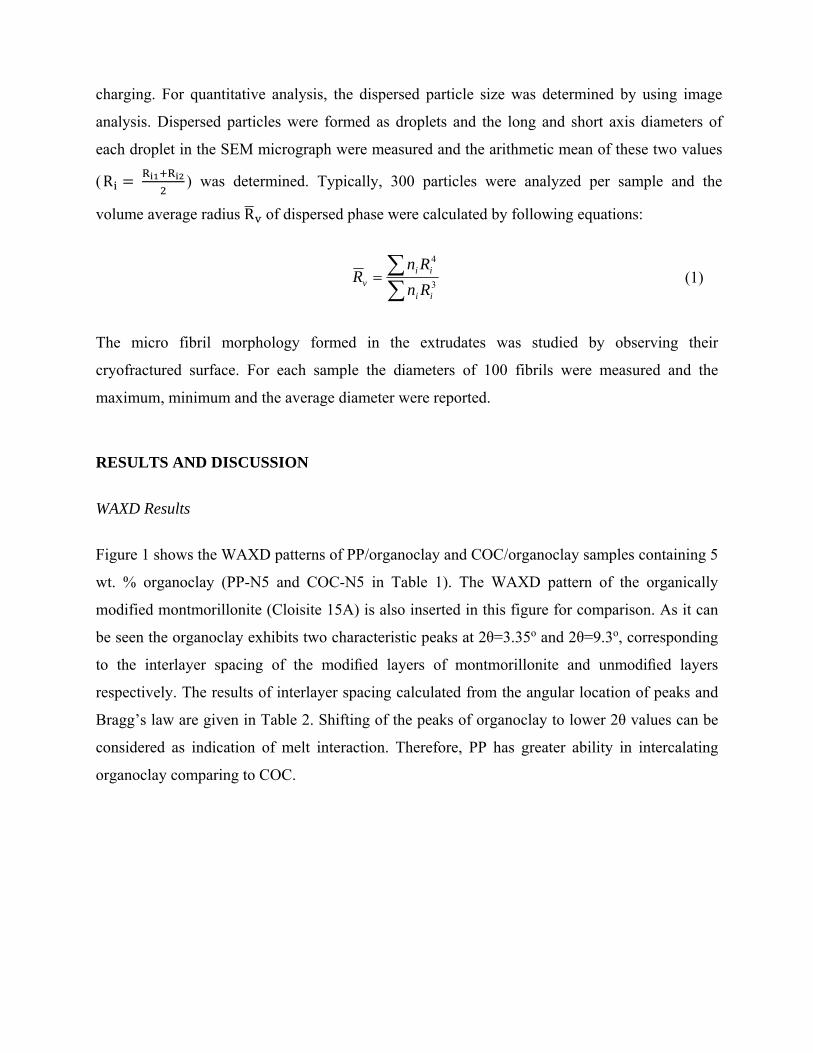
charging. For quantitative analysis, the dispersed particle size was determined by using image
analysis. Dispersed particles were formed as droplets and the long and short axis diameters of
each droplet in the SEM micrograph were measured and the arithmetic mean of these two values
(R ) was determined. Typically, 300 particles were analyzed per sample and the
volume average radius R of dispersed phase were calculated by following equations:
(1)
The micro fibril morphology formed in the extrudates was studied by observing their
cryofractured surface. For each sample the diameters of 100 fibrils were measured and the
maximum, minimum and the average diameter were reported.
RESULTS AND DISCUSSION
WAXD Results
Figure 1 shows the WAXD patterns of PP/organoclay and COC/organoclay samples containing 5
wt. % organoclay (PP-N5 and COC-N5 in Table 1). The WAXD pattern of the organically
modified montmorillonite (Cloisite 15A) is also inserted in this figure for comparison. As it can
be seen the organoclay exhibits two characteristic peaks at 2θ=3.35o and 2θ=9.3o, corresponding
to the interlayer spacing of the modified layers of montmorillonite and unmodified layers
respectively. The results of interlayer spacing calculated from the angular location of peaks and
Bragg’s law are given in Table 2. Shifting of the peaks of organoclay to lower 2θ values can be
considered as indication of melt interaction. Therefore, PP has greater ability in intercalating
organoclay comparing to COC.
3
4
ii
iiv Rn
RnR

Figure 1. X-ray diffraction patterns of the organically modified montmorillonite (Cloisite 15A),
PP-N5 and COC-N5.
Table 2. The inter-layer spacing values corresponding to the WAXD patterns shown in Figure1.
sample Position (2θ) d-spacing (A)
Cloisite 15A 3.35 26
PP-N5 2.61 34
COC-N5 3.01 29
Linear Melt Viscoelastic Results
Figure 2 presents the storage modulus, G’ as a function of angular frequency for PP, COC,
PP80/COC20 and COC80/PP20 samples. As it can be seen clearly, PP and COC exhibit terminal
behavior at low frequencies. Interestingly, the low frequency storage modulus values of the
blend samples are higher than their individual components with greater enhancement for
PP80/COC20, as shown in the marked region. Slouf et al. have studied the phase disengagement
mechanism in PP/COC blends and found that PP is not miscible with COC [38], thus the upraise
in the low frequency storage modulus values for the blends PP80/COC20 and COC80/PP20 can
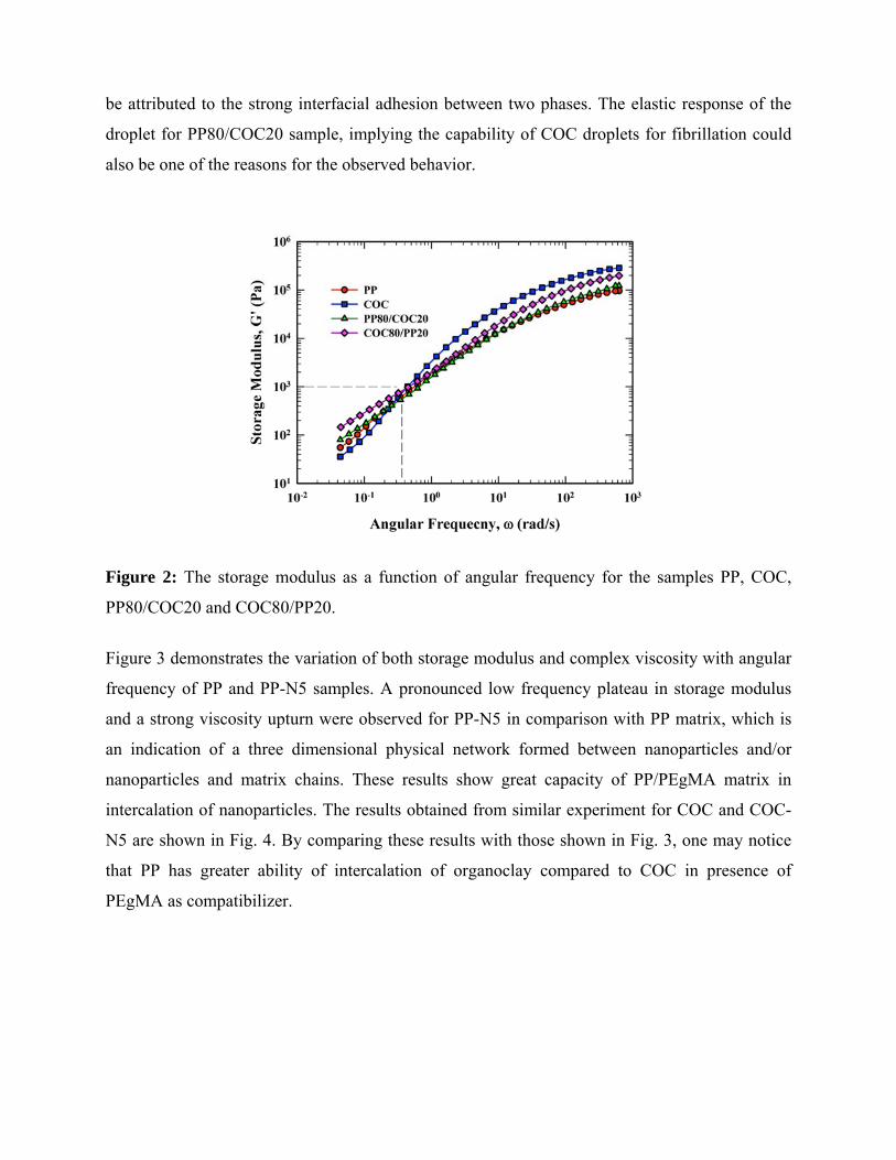
be attributed to the strong interfacial adhesion between two phases. The elastic response of the
droplet for PP80/COC20 sample, implying the capability of COC droplets for fibrillation could
also be one of the reasons for the observed behavior.
Figure 2: The storage modulus as a function of angular frequency for the samples PP, COC,
PP80/COC20 and COC80/PP20.
Figure 3 demonstrates the variation of both storage modulus and complex viscosity with angular
frequency of PP and PP-N5 samples. A pronounced low frequency plateau in storage modulus
and a strong viscosity upturn were observed for PP-N5 in comparison with PP matrix, which is
an indication of a three dimensional physical network formed between nanoparticles and/or
nanoparticles and matrix chains. These results show great capacity of PP/PEgMA matrix in
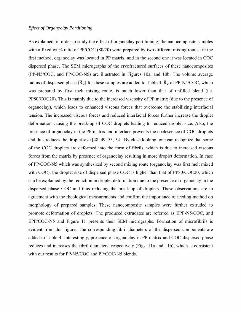
intercalation of nanoparticles. The results obtained from similar experiment for COC and COC-
N5 are shown in Fig. 4. By comparing these results with those shown in Fig. 3, one may notice
that PP has greater ability of intercalation of organoclay compared to COC in presence of
PEgMA as compatibilizer.
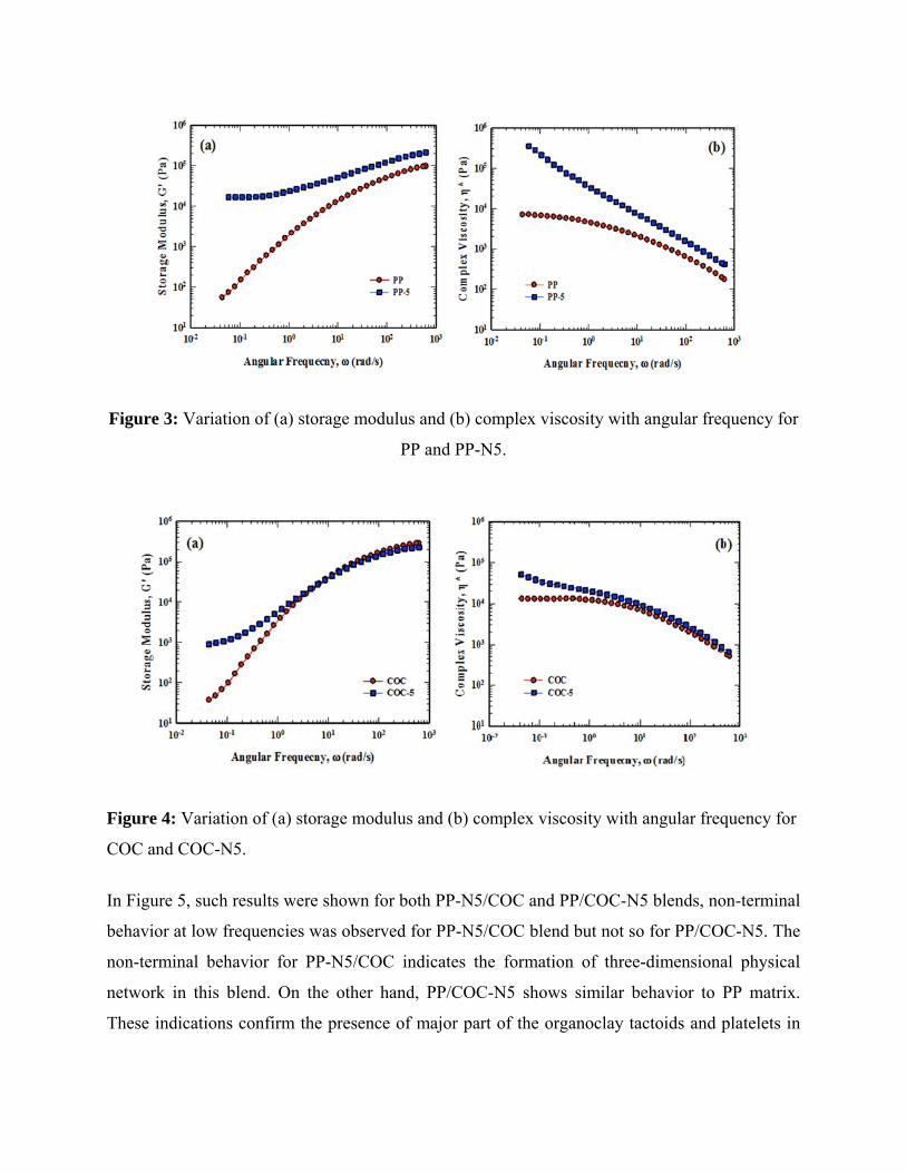
Figure 3: Variation of (a) storage modulus and (b) complex viscosity with angular frequency for
PP and PP-N5.
Figure 4: Variation of (a) storage modulus and (b) complex viscosity with angular frequency for
COC and COC-N5.
In Figure 5, such results were shown for both PP-N5/COC and PP/COC-N5 blends, non-terminal
behavior at low frequencies was observed for PP-N5/COC blend but not so for PP/COC-N5. The
non-terminal behavior for PP-N5/COC indicates the formation of three-dimensional physical
network in this blend. On the other hand, PP/COC-N5 shows similar behavior to PP matrix.
These indications confirm the presence of major part of the organoclay tactoids and platelets in

the PP matrix for PP-N5/COC and in the COC dispersed phase for PP/COC-N5. Discussed
results confirm the importance of feeding procedure in determining the location of organocly.
Figure 5: Variation of (a) storage modulus and (b) complex viscosity with angular frequency for
PP-N5/COC and PP/COC-N5.
The effect of temperature on the storage modulus and complex viscosity of PP and COC is
shown in Figure 6. It is very clear that PP is less thermo-sensitive than COC as the variation in
storage modulus and complex viscosity of COC with temperature is very high compared to that
of PP. This kind of behavior is very crucial in the cooling phase of the blend in the single
extruder to save the generated morphology of PP/COC blends when COC is the dispersed phase.

Figure 6: Effect of temperature on the storage modulus (a) and complex viscosity (b) of PP and
COC.
Morphology using SEM results
Morphology of Blends
Figures 7a and 7b demonstrate the SEM micrographs of the cryofractured surface of the blends
PP80/COC20, and COC80/PP20. As it can be seen, both blends exhibit a typical matrix-
dispersed morphology where dispersed phase forms droplets finely dispersed in matrix due to the
strong interfacial adhesion of the blend components. The average particle size measurements
were performed on these SEM micrographs and the results are listed in Table 3.
Figure 7: SEM micrographs of the cryofractured surface of the blend samples (a) PP80/COC20,
(b) COC80/PP20.

Table 3. Volume average radius, (µm), of PP80/COC20, PP-N5/COC and PP/COC-N5
blends.
Sample R (µm)
PP80/COC20 0.73
COC80/PP20 0.4
PP-N5/COC 0.33
PP/COC-N5 0.81
Morphology of Unfilled Extrudates
As can be noticed from Figure 7, morphology of the prepared blends PP80/COC20, and
COC80/PP20 is established and stabilized via mixing in twin-screw extruder. As discussed in the
experimental section, these blends were further extruded through a single-screw extruder to
achieve microfibril formation of the dispersed phase. The obtained extrudates are referred as
EPP80/COC20, and ECOC80/PP20, respectively, and their SEM micrographs are presented in
Fig. 8. It is evident from Fig. 8. that the droplets formed in twin-screw extruder are converted to
microfibrils by passing through the attached die of single-screw extruder. The corresponding
fibril diameters of the dispersed components are listed in Table 4. Each sample is characterized
by three values (the minimum, maximum, and average fibril diameter). These results suggest that
in PP/COC blend system, unlike many other thermoplastic blends, which have only circular
dispersed phase in the extruded samples, microfibril formation of droplets has occurred in the
shear flow fields without any post processing such as fiber spinning [37, 38, 58]. The formation
of fibrils in immiscible blends is mainly because of the enhanced viscous stresses (intending to
deform the droplets) over interfacial stresses (trying to keep droplet shape unchanged) that
causes increase in the droplet deformation and fibrillation. For ECOC80/PP20, high viscosity of
matrix (COC) comparing to dispersed phase (PP) is in favor of viscous stresses and promotes
fibrillation. Moreover, high glass transition temperature of COC matrix stabilizes PP fibrils and
prevents PP from returning to circular form. For EPP80/COC20, although viscosity ratio is
unfavorable for fibrillation, microfibrils of COC are observed. This can be attributed to the high

elasticity of COC that prevents droplet breakup in the favor of fibrillation. Moreover, its high
glass transition (140 oC), leads to fast solidification of deformed droplets in the extrudates [37,
59-62]. The capillary stability and the capability of COC in fibril formation also have their
contribution. This supports our argument on the rheology results, regarding the high elasticity of
droplet deformation in PP80/COC20 blend at low frequencies.
Figure 8: SEM micrographs of the extruded samples (a) EPP80/COC20, (b) ECOC80/PP20.
Table 4: Diameters of the fibers of the dispersed component in the matrix of the extruded
polymer blends.
Sample Fibril diameter (µm)
Minimum (µm) Maximum (µm) Average (µm)
EPP80/COC20 0.15 0.774 0.462
ECOC80/PP20 0.42 1.329 0.874
EPP-N5/COC 0.11 0.526 0.318
EPP/COC-N5 0.134 0.872 0.503

Effect of Shear Rate
The effect of shear rate on the droplet deformation and microfibril formation is further studied by
employing three different screw speeds of 6, 60 and 120 rev/min corresponding to shear rates of
8, 72, and 143 s-1, respectively in the single-screw extruder, for the blend PP80/COC20. The
SEM micrographs of cryofractured surfaces of extrudates under these three different shear rates
are shown in Fig. 9 and the corresponding fibril diameters are listed in Table 5. As can be
noticed from the SEM micrographs and the values listed in Table 5, the droplet size decreases
with increase in the shear rate. It is also evident that the microfibril formation of COC droplets
increases with increasing shear rate; for shear rates 72 and 143 s-1 the presence of COC fibrils in
PP matrix is clearly observed.
Figure 9: SEM micrographs of cryofractured surface of PP80/COC20 blend under these three
different shear rates (a) 7.58 s-1 (b) 72.10 s-1 and (c) 142.71 s-1.
Table 5: The particle size dimensions of extruded PP/COC blend under different shear rates.
Sample Shear rate (1/s) Fibril diameter
(µm)
EPP80/COC20
7.58 0.75
72.10 0.46
142.71 0.29
Effect of Organoclay Partitioning
As explained, in order to study the effect of organoclay partitioning, the nanocomposite samples
with a fixed wt.% ratio of PP/COC (80/20) were prepared by two different mixing routes; in the
first method, organoclay was located in PP matrix, and in the second one it was located in COC
dispersed phase. The SEM micrographs of the cryofractured surfaces of these nanocomposites
(PP-N5/COC, and PP/COC-N5) are illustrated in Figures 10a, and 10b. The volume average
radius of dispersed phase (R ) for these samples are added to Table 3. R of PP-N5/COC, which
was prepared by first melt mixing route, is much lower than that of unfilled blend (i.e.
PP80/COC20). This is mainly due to the increased viscosity of PP matrix (due to the presence of
organoclay), which leads to enhanced viscous forces that overcome the stabilizing interfacial
tension. The increased viscous forces and reduced interfacial forces further increase the droplet
deformation causing the break-up of COC droplets leading to reduced droplet size. Also, the
presence of organoclay in the PP matrix and interface prevents the coalescence of COC droplets
and thus reduces the droplet size [48, 49, 53, 54]. By close looking, one can recognize that some
of the COC droplets are deformed into the form of fibrils, which is due to increased viscous
forces from the matrix by presence of organoclay resulting in more droplet deformation. In case
of PP/COC-N5 which was synthesized by second mixing route (organoclay was first melt mixed
with COC), the droplet size of dispersed phase COC is higher than that of PP80/COC20, which
can be explained by the reduction in droplet deformation due to the presence of organoclay in the
dispersed phase COC and thus reducing the break-up of droplets. These observations are in
agreement with the rheological measurements and confirm the importance of feeding method on
morphology of prepared samples. These nanocomposite samples were further extruded to
promote deformation of droplets. The produced extrudates are referred as EPP-N5/COC, and
EPP/COC-N5 and Figure 11 presents their SEM micrographs. Formation of microfibrils is
evident from this figure. The corresponding fibril diameters of the dispersed components are
added to Table 4. Interestingly, presence of organoclay in PP matrix and COC dispersed phase
reduces and increases the fibril diameters, respectively (Figs. 11a and 11b), which is consistent
with our results for PP-N5/COC and PP/COC-N5 blends.

Figure 10: SEM micrographs of the cryofractured surface of the nanocomposites (a) PP-
N5/COC, and (b) PP/COC-N5.
Figure 11: SEM micrographs of the extruded nanocomposites (a) EPP-N5/COC, and (b)
EPP/COC-N5.
MORPHOLOGY PREDICTION
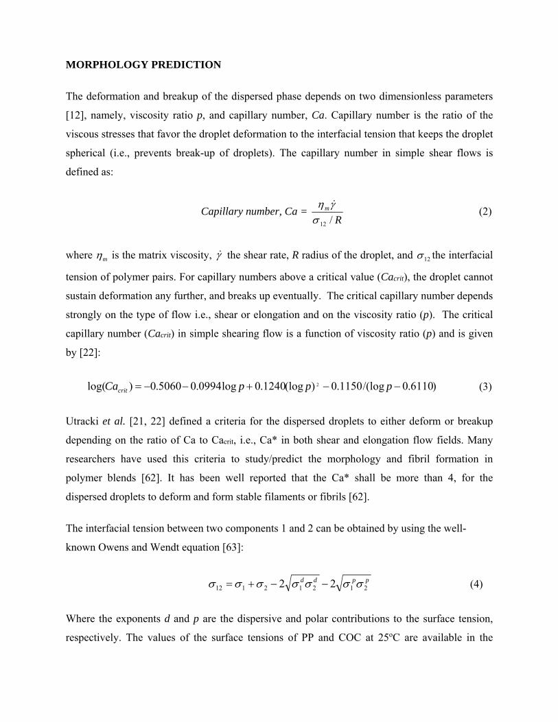
The deformation and breakup of the dispersed phase depends on two dimensionless parameters
[12], namely, viscosity ratio p, and capillary number, Ca. Capillary number is the ratio of the
viscous stresses that favor the droplet deformation to the interfacial tension that keeps the droplet
spherical (i.e., prevents break-up of droplets). The capillary number in simple shear flows is
defined as:
Capillary number, Ca = (2)
where is the matrix viscosity, the shear rate, R radius of the droplet, and the interfacial
tension of polymer pairs. For capillary numbers above a critical value (Cacrit), the droplet cannot
sustain deformation any further, and breaks up eventually. The critical capillary number depends
strongly on the type of flow i.e., shear or elongation and on the viscosity ratio (p). The critical
capillary number (Cacrit) in simple shearing flow is a function of viscosity ratio (p) and is given
by [22]:
(3)
Utracki et al. [21, 22] defined a criteria for the dispersed droplets to either deform or breakup
depending on the ratio of Ca to Cacrit, i.e., Ca* in both shear and elongation flow fields. Many
researchers have used this criteria to study/predict the morphology and fibril formation in
polymer blends [62]. It has been well reported that the Ca* shall be more than 4, for the
dispersed droplets to deform and form stable filaments or fibrils [62].
The interfacial tension between two components 1 and 2 can be obtained by using the well-
known Owens and Wendt equation [63]:
(4)
Where the exponents d and p are the dispersive and polar contributions to the surface tension,
respectively. The values of the surface tensions of PP and COC at 25oC are available in the
Rm
/12
m 12
)6110.0/(log1150.0)(log1240.0log0994.05060.0)log( 2 pppCacrit
ppdd21212112 22

literature [64, 65]. By using the temperature dependency relationship, the surface tension at 235 oC (processing temperature) can be calculated. The extrapolated values of the surface tension at
235 oC for components are given in Table 6. The calculated surface tension between PP and
COC is 5.74 mN/m according to equation (4). For obtaining morphological and interfacial
information on immiscible blends, the emulsion model of Palierne [66] has been used. The
interfacial tension σ12 for these blends is obtained by fitting their experimental and calculated
complex modulus. The value of interfacial tension σ12 is found to be 6.8 mN/m for PP-N5/COC
and 7.1 mN/m for PP/COC-N5 samples.
Table 6: Values of surface tension of the components at 235oC.
Material Total surface tension
(mN/m)
Dispersive surface
tension, (mN/m)
Polar surface
tension,
(mN/m)
(mN/m.K)
PP 17.5 17.5 - -0.06
COC 14.98 10.216 3.317 -0.08
Cloisite15A 19.37 6.98 12.39 -
For PP-N5/COC, we assumed all the organoclay has remained in the matrix (i.e., no migration
into the dispersed phase) and we used the viscosity of PP-N5 as the viscosity of the matrix.
Similarly, for PP/COC-N5, all the organoclay content was assumed to be in the dispersed phase
and the viscosity of COC-N5 was considered to be the viscosity of the dispersed phase. The Cox-
Merz rule relates steady state non-linear material functions to linear viscoelastic properties as
depicted by the following relationship.
lim→
lim→
′ ω (5)
We assumed that Cox-Merz rule is applicable to estimate the viscosities of the matrix and the
dispersed phase and thus to calculate the viscosity ratio (p), at shear rate of 72 s-1 which was used
in our experiments. Given the viscosities of the matrix and the dispersed phase, capillary number
and the critical capillary number values for the extruded samples EPP80/COC20,
d p dT
d

ECOC80/PP20, EPP-N5/COC, and EPP/COC-N5 were calculated by using equations (2) and (3).
These values are presented in Table 7.
Table 7: The capillary number and the critical capillary number values for the extruded polymer
blends.
Sample Rv (µm) p Ca Cacrit Ca*
EPP80/COC20 0.73 3.125 7.15 2.919 2.45
ECOC80/PP20 0.4 0.32 12.25 0.476 25.75
EPP-N5/COC 0.33 1.25 6.82 0.512 13.32
EPP/COC-N5 0.81 3.205 6.97 3.706 1.88
As shown in Figures 8 and 11, microfibrillation of the dispersed phase is observed for all the
samples. The formation of microfibrils is expected for samples EPP-N5/COC and
ECOC80/PP20, as the Ca* (i.e., the ratio of capillary number to the critical capillary number)
values meet the criteria proposed by Utracki et al. [21, 22] (refer to Table 7). Even though the
values of Ca* for samples EPP80/COC20 and EPP/COC-N5 are less than 4, microfibril
formation of COC was observed. This can be attributed to the higher viscosity and elasticity of
COC in comparison with PP, which leads to a more rigid structure in the molten state that
inhibits the droplet breakup and favors the fiber formation. Also, sharp increase in the elasticity
upon cooling and high glass transition of COC help saving the generated morphology when the
COC is the dispersed phase (refer to Fig. 6). The parameters such as elasticity and glass
transition of the dispersed phase are not considered in the Utracky's theory, and this may be the
cause for the discrepancy observed between the morphology from SEM and prediction of
Utracky's theory.

CONCLUSIONS
Rheological and morphological characteristics of PP/COC blends and PP/COC/organoclay have
been studied using WXRD, linear viscoelastic measurements. The results indicated that the
morphology of these blends, especially the size of the dispersed phase, depends strongly on
organoclay partitioning, as evident from SEM micrographs as well. Temperature sweep
measurements of storage modulus and complex viscosities of pure components PP and COC
showed that COC is very thermosensitive in comparison with PP, which may be responsible for
the generated morphology of PP/COC blends when the COC is in the dispersed phase during the
cooling phase of the blend.
In addition, the effect of shear rate (in the single-screw extruder) on the microfibrillation
capability of PP/COC blends has been investigated. The SEM micrographs of cryofractured
surfaces of PP/COC blend at three different shear rates indicated that the droplet size decreases
with increase in the shear rate. However, the polydispersity and microfibril formation of COC
droplets increased with the shear rate. In contrast to many other polymers blends, it was observed
that microfibril formation of COC droplets has occurred in the shear flow fields without any post
processing. This is mainly because of the enhanced hydrodynamic stress over interfacial stress.
The high glass transition of COC may also have considerable contribution.
The fibrillation of COC was found to be strongly dependent on the partitioning of organoclay.
When the organoclay is in the PP matrix, the increased viscous forces over interfacial forces
causes enhanced COC droplet deformation and thus leading to reduced droplet size. Presence of
the organoclay in COC droplets, reduces the deformability and therefore fibrillation of COC.
Although the ratio of capillary number to the critical capillary number is less than 4, microfibril
formation of COC is observed for few PP/COC extruded blends, in contrast to the fibril
formation criteria defined by Utracki theory [21, 22]. This can be attributed to high elasticity and
glass transition of the dispersed phase that are not included in the Utracky's theory.

REFERENCES
1. C. B. Bucknall, Toughened plastics, Applied Science Publication, London (1977).
2. L. A. Utracki, Polymer alloys and blends, Hanser Publication, Munich (1990).
3. M. J. Folkes, and P. S. Hope, Polymer blends and alloys, Chapman and Hall, Cambridge
(1993).
4. L. H. Sperling, Polymeric multicomponent materials, Wiley, New York (1997).
5. J. Varga, A. Breining, and G. W. Ehrenstein, Int. Polym. Proc. XV, 53 (2000).
6. D. R. Paul, and S. Newman, Polymer blends. New York: Academic Press (1978).
7. J. Li, and B. D. Favis, Polymer, 42, 5047 (2001).
8. A. Leclair, and B. D. Favis, Polymer, 37, 4723 (1996).
9. Y.X. Pang, M.D. Jia, H.J. Hu, D.J. Hourston, and M. Song. Polymer, 41,357 (2000).
10. C. H. Song, and A. I. Isayev, Polymer, 42(6), 2611 (2001).
11. P. Pötschke, and D. R. Paul, J. Macro. Sci., Part C, 43, 87 (2003).
12. G. I. Taylor, Proc. R. Soc. Lond., A1, 38 (1932).
13. G. I. Taylor, Proc. R. Soc. London, Ser. A., 146, 501 (1934).
14. F. D. Rumscheidt and S. G. Mason, J. Colloid Sci. 16, 238 (1961).
15. H. P. Grace, Chem. Eng. Commun., 14, 225 (1982).
16. S. Torza, R. G. Cox, and S. G. Mason, J. Colloid Interface Sci., 38, 395 (1972).
17. B. J. Bentley and L. G. Leal, J. Fluid Mech. 167, 241 (1986).
18. S. Guido and M. Villone, J. Rheol. 42, 395 (1998).
19. V. Cristini, S. Guido, A. Alfani, J. Blawzdziewicz, and M. Loewenberg, J. Rheol. 47, 1283
(2003).
20. D. Barthes-Biesel and A. Acrivos, J. Fluid Mech. 61, 1 (1973).
21. L. A. Utracki, and Z. H. Shi, Polym. Eng. Sci., 32, 1824 (1992).
22. M. A. Huneault, Z. H. Shi, and L. A. Utracki, Polym. Eng. Sci., 35(1), 115 (1995).
23. D. Sapoundjieva, Z. Denchev, M. Evstatiev, S. Fakirov, N. Stribeck, and M. J. Stamm,
Mater. Sci., 34(13), 3063 (1999).
24. M. F. Boyaud, A. Ait-Kadi, M. Bousmina, A. Michel, and P. Cassagnau, Polymer, 42(15),
6515 (2001).
25. A. Monticciolo, P. Cassagnau, and A. Michel, Polym. Eng. Sci., 38(11), 1882 (1998).
26. J. C. Chen, and I. R. Harrison, Polym. Eng. Sci., 36(2), 371 (1998).

27. X. D. Li, M. C. Chen, Y. H. Huang, and G. M. Cong, Polym. Eng. Sci., 39(5), 881 (1999).
28. Z. M. Li, M. B. Yang, W. Yang, R. Huang, and J. M. Feng, Polym. Plast. Technol. Eng.,
41(1), 19 (2002).
29. M. Evstatiev, and S. Fakirov, Polymer, 33, 877 (1992).
30. S. Fakirov, M. Evstatiev, and S. Petrovich, Macromolecules, 26, 5219 (1993).
31. S. Fakirov, and M. Evstatiev, Adv. Mate., 6, 395 (1994).
32. A. Isayev, and P. R. Subramanian, U.S. Patent 5070157 (1991).
33. A. Mehta, and A. Isayev, Polym. Eng. Sci., 31, 971 (1991).
34. G. Khanarian, Polym. Eng. Sci., 40, 2590 (2000).
35. W. J. Huang, F. C. Chang, and P. P. J. Chu, Polymer, 41, 6095 (2000).
36. T. Scrivani, R. Benavente, E. Perez, and J. M. Perena, Macromol. Chem. Phys., 202, 2547
(2001).
37. A. Pegoretti, K. J. Koları´, L. Fambri, and A. Penati, Polymer, 44, 3381(2003).
38. M. Slouf, J. Kolarik, and L. Fambri, J. Appl. Polym. Sci., 91, 253 (2004).
39. L. Fambri, J. Kolarik, E. Pasqualini, A. Penati, and A. Pegoretti, Macromol. Symp., 263,
114 (2008).
40. O.B. Usta, D. Perchak, A. Clarke, J.M. Yeomans, and A.C. Balazs, J. Chem. Phys., 130
(2009).
41. W. S. Chow, Z. A. Mohd Ishak, J. Kargar-Kocsis, A. A. Apostolov, and U. S. Ishiaku,
Polymer, 44, 7427 (2003).
42. S. S. Ray, S. Pouliot, M. Bousmina, and L. A. Utracki, Polymer, 45, 8403 (2004)
43. H. Zou, K. Wang, Q. Zhang, and Q. Fu, Polymer, 47, 7821 (2006).
44. T. Gcwabaza, S. S. Ray, W. W. Focke, and A. Maity, Eur. Polym. J., 45, 353 (2009).
45. C. I. W. Calcagno, C. M. Mariani, S. R. Teixeira, and R. S. Mauler, Compos. Sci. and
Technol., 68, 2193 (2008).
46. M. Kong, Y. Huang, G. Chen, Q. Yang, and G. Li, Polymer, 52, 5231 (2011).
47. A. Gooneie, H. Nazockdast, F. Shahsavan, Polym. Eng. and Sci., (2015).
48. B. Zhang, Y. Ding, P. Chen, C. Liu, J. Zhang, J. He, and G. H. Hu, Polymer, 46, 5385
(2005).
49. A. Bigdeli, H. Nazockdast, A. rashidi, and M. E. Yazdanshenas, J. Polym. Res., 19, 9990
(2012).
50. J.C. Lepers, B.D. Favis, and R.J Tabar. J Polym Sci Part B Polym Phys., 35, 2271 (2006).

51. J. S. Hong, H. Namkung, K. H. Ahn, S. J. Lee, and C. Kim, Polymer, 47, 3967 (2006).
52. J. S. Hong, Y. K. Kim, K. H. Ahn, S. J. Lee, and C. Kim, Rheol. Acta, 46, 469 (2007).
53. L. Elias, F. Fenouillot, J.C. Majeste, and P. Cassagnau, Polymer, 48, 6029 (2007).
54. L. Elias, F. Fenouillot, J.C. Majeste, G. Martin, and P. Cassagnau, J. Polym. Sci., Part B:
Polym. Phys., 46, 1976 (2008).
55. L. Liu, Y. Wang, Y. Li, J. Wu, Z. Zhou, and C. Jiang, Polymer, 50, 3072 (2009).
56. L. Liu, H. Wu, Y. Wang, J. Wu, Y. Peng, F. Xiang, and J. Zhang, J. Polym. Sci., Part B:
Polym. Phys., 48, 1882 (2010).
57. A. C. Baudouin, D. Auhl, F. Tao, J. Devaux, and C. Bailly, Polymer, 52, 149 (2011).
58. K. Friedrich, M. Evstatiev, S. Fakirov, O. Evstatiev, M. Ishii, and M. Harrass, Compo. Sci.
Technol., 65, 107 (2005).
59. J. Forsyth, J. M. Perena, R. Benavente, E. Perez, I. Tritto, L. Boggioni, and H. H.
Brintzinnger, Macromol. Chem. Phys., 202, 614 (2001).
60. J. Forsyth, T. Scrivani, R. Benavente, C. Marestin, and J. M. Perena, Appl. Polym. Sci., 82,
2159 (2001).
61. Topas (COC) booklet, Ticona: Hoechst, Germany (1995).
62. M. A. Huneault, Z. H. Shi, and L. A. Utracki, Polym. Eng. Sci., 35(1), 115 (1995).
63. K. D. Owens, and R. C. Wendt, J. Appl. Polym. Sci., 13(8), 1741 (1969).
64. R. Foudazi, and H. Nazockdast, Appl. Rheol., 20, 12218 (2010).
65. J. Y. Shn, and J. Y. Park, Pure Appl. Chem., 77, 801 (2005).
66. J. F. Palierne, Rheol. Acta., 29, 204 (1991).