Embed Size (px)
Citation preview

Funded by the European Union
University of Bristol
AEROGUST Workshop27th - 28th April 2017, University of Liverpool
Presented by Robbie Cook and Chris Wales
Funded by the European Union
Overview• Theory
• Nonlinear structural solver coupled with unsteady aerodynamics
• Gust loads process for nonlinear aeroelastic systems
• Results• WP2 recap of M18 results
• WP3 Uncertainty Quantification initial results
• Conclusions and next steps
AEROGUST WORKSHOP

Funded by the European Union
Nonlinear Aeroelastic Framework
EOM
Strain-Curvature/Velocity
Relation
• Additional equation required to satisfy free-free conditions• Free-free velocity couples with second equation above
• Allows for arbitrarily large rigid body rotations
• Linear finite-elements are used to solve the structural EOM
• Positions and orientations are obtained by integrating strains/curvatures along the beam, or, velocities with time (parameterising rotations using quaternions)
• Free-free geometrically-exact nonlinear beam code based on Hodges’ intrinsic beam formulation• Linear strain-curvature/force-moment relationship
• Large beam deformations and rotations capture
AEROGUST WORKSHOP
Funded by the European Union
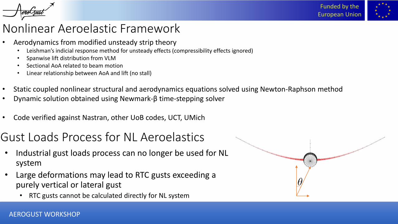
• Aerodynamics from modified unsteady strip theory• Leishman’s indicial response method for unsteady effects (compressibility effects ignored)• Spanwise lift distribution from VLM• Sectional AoA related to beam motion• Linear relationship between AoA and lift (no stall)
• Static coupled nonlinear structural and aerodynamics equations solved using Newton-Raphson method• Dynamic solution obtained using Newmark-β time-stepping solver
• Code verified against Nastran, other UoB codes, UCT, UMich
Gust Loads Process for NL Aeroelastics• Industrial gust loads process can no longer be used for NL
system
• Large deformations may lead to RTC gusts exceeding a purely vertical or lateral gust• RTC gusts cannot be calculated directly for NL system
Nonlinear Aeroelastic Framework
AEROGUST WORKSHOP

Funded by the European Union
Vertical gust vs. angled gust on free-flying aircraft
Θ=0o Θ=60o
AEROGUST WORKSHOP
Funded by the European Union
WP2
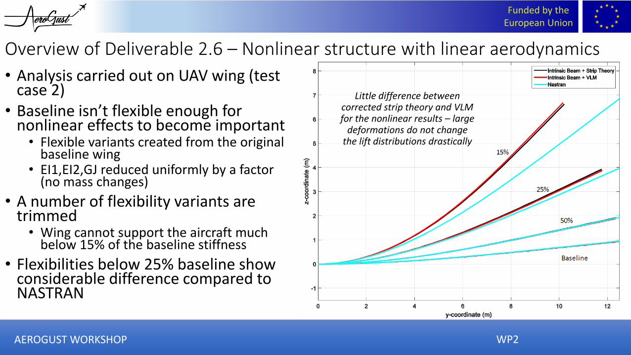
• Analysis carried out on UAV wing (test case 2)
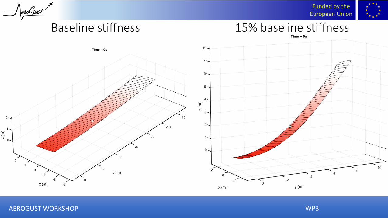
• Baseline isn’t flexible enough for nonlinear effects to become important• Flexible variants created from the original
baseline wing• EI1,EI2,GJ reduced uniformly by a factor
(no mass changes)
• A number of flexibility variants are trimmed • Wing cannot support the aircraft much
below 15% of the baseline stiffness
• Flexibilities below 25% baseline show considerable difference compared to NASTRAN
Little difference between corrected strip theory and VLM for the nonlinear results – large
deformations do not change the lift distributions drastically
Overview of Deliverable 2.6 – Nonlinear structure with linear aerodynamics
AEROGUST WORKSHOP

Funded by the European Union
WP3
• Part of Task 3.3, addresses WP3 objectives• “To assess the impact of the underlying assumptions of the cuurent loads
process”• “To investigate methods to extend the applicability of the current process to
highly flexible and innovative structures”• “To develop methods to include the uncertainty present in both the
aerodynamic and structural models within the current loads process and investigate the impact on gust loads”
Work Package 3: Overview of Deliverable 3.10Effects of uncertainty on the gust loads process
AEROGUST WORKSHOP
Funded by the European Union
AEROGUST WORKSHOP WP3
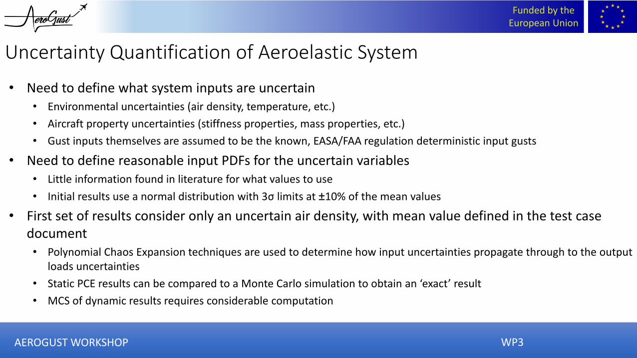
• Need to define what system inputs are uncertain• Environmental uncertainties (air density, temperature, etc.)
• Aircraft property uncertainties (stiffness properties, mass properties, etc.)
• Gust inputs themselves are assumed to be the known, EASA/FAA regulation deterministic input gusts
• Need to define reasonable input PDFs for the uncertain variables• Little information found in literature for what values to use
• Initial results use a normal distribution with 3σ limits at ±10% of the mean values
• First set of results consider only an uncertain air density, with mean value defined in the test case document• Polynomial Chaos Expansion techniques are used to determine how input uncertainties propagate through to the output
loads uncertainties
• Static PCE results can be compared to a Monte Carlo simulation to obtain an ‘exact’ result
• MCS of dynamic results requires considerable computation
Uncertainty Quantification of Aeroelastic System

Funded by the European Union
AEROGUST WORKSHOP
Work Package 3: Overview of Deliverable 3.10Effects of uncertainty on the gust loads process
UQ Analysis –Aeroelastic Trim Analysis (Static)
WP3

Funded by the European Union
• MCS carried out with 1000 trim cases at different air densities
• MSC PDF histograms for AoA compared to PCE PDFs calculated with 5 trim cases and 4 shape functions
• Good agreement to MCS from PCE using fewer simulations
• Trim loads do not vary much with air density
1000 simulation
Monte Carlo ‘exact’
solution
Polynomial Chaos
emulation from subset
of results
WP3AEROGUST WORKSHOP

Funded by the European Union
WP3
• Mean values calculated from PCE values match well with the values calculated with the mean air density values
AEROGUST WORKSHOP

Funded by the European Union
WP3
• Standard deviations appear to remain roughly constant for linear system regardless of flexibility
• Standard dev increases in nonlinear system
AEROGUST WORKSHOP

Funded by the European Union
WP3
• Skewness and kurtosis plots included as a first case indication of how normal the output distributions are
• Small amount of skewness is seen for linear and nonlinear, and excess kurtosis is low –fairly normal output PDFs
AEROGUST WORKSHOP

Funded by the European Union
WP3
Work Package 3: Overview of Deliverable 3.10Effects of uncertainty on the gust loads process
UQ Analysis – Aeroelastic Gust Analysis (Dynamic)
AEROGUST WORKSHOP
Funded by the European Union
WP2
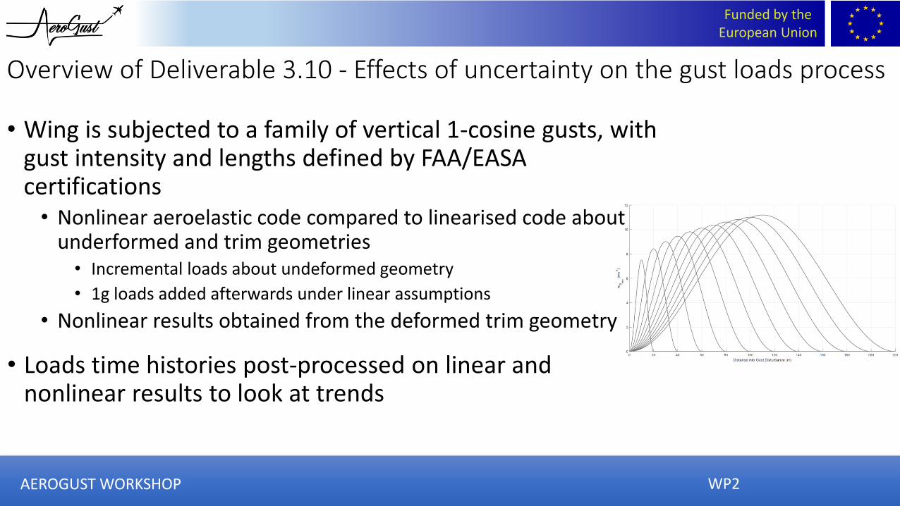
Overview of Deliverable 3.10 - Effects of uncertainty on the gust loads process
• Wing is subjected to a family of vertical 1-cosine gusts, with gust intensity and lengths defined by FAA/EASA certifications• Nonlinear aeroelastic code compared to linearised code about
underformed and trim geometries• Incremental loads about undeformed geometry
• 1g loads added afterwards under linear assumptions
• Nonlinear results obtained from the deformed trim geometry
• Loads time histories post-processed on linear and nonlinear results to look at trends
AEROGUST WORKSHOP

Funded by the European Union
WP3
• RTC gust direction calculated from linear system about trim geometry
• Even for stiff wings, the worst case gust is orientated away from purely vertical• Can lead to loads
increases ~10%
• May be exacerbated by fixed-root assumptions
AEROGUST WORKSHOP
Funded by the European Union
WP3
Baseline stiffness 15% baseline stiffness
AEROGUST WORKSHOP
Funded by the European Union
WP3
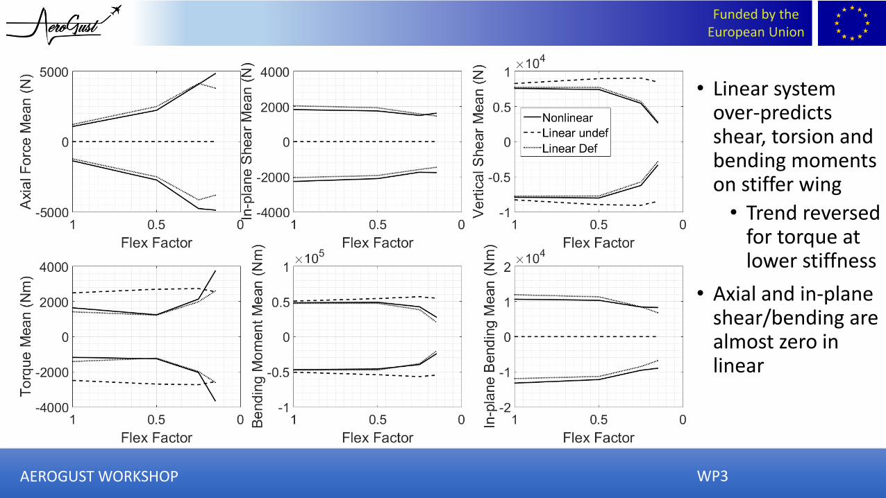
• Linear system over-predicts shear, torsion and bending moments on stiffer wing
• Trend reversed for torque at lower stiffness
• Axial and in-plane shear/bending are almost zero in linear
AEROGUST WORKSHOP

Funded by the European Union
WP3
• Standard deviation of the linear system output PDFs remains fairly constant for different flexibilities
• Standard dev reduces significantly for root shear, torque and bending moment as aircraft gets more flexible
• Opposite trend as seen in trim AoA
AEROGUST WORKSHOP
Funded by the European Union
WP3
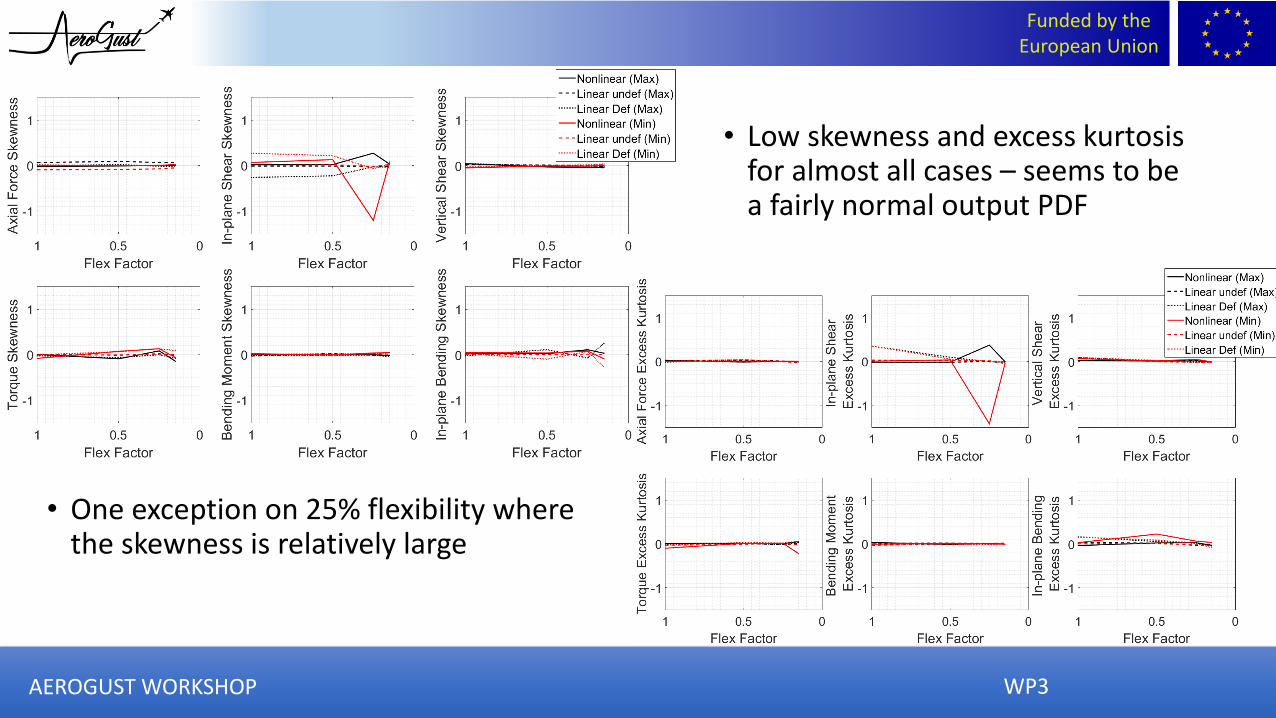
• Low skewness and excess kurtosis for almost all cases – seems to be a fairly normal output PDF
• One exception on 25% flexibility where the skewness is relatively large
AEROGUST WORKSHOP
Funded by the European Union
AEROGUST WORKSHOP
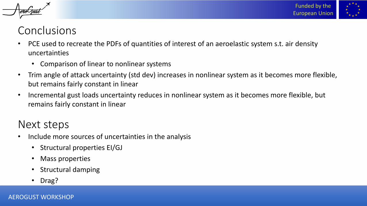
Conclusions• PCE used to recreate the PDFs of quantities of interest of an aeroelastic system s.t. air density
uncertainties
• Comparison of linear to nonlinear systems
• Trim angle of attack uncertainty (std dev) increases in nonlinear system as it becomes more flexible, but remains fairly constant in linear
• Incremental gust loads uncertainty reduces in nonlinear system as it becomes more flexible, but remains fairly constant in linear
Next steps• Include more sources of uncertainties in the analysis
• Structural properties EI/GJ
• Mass properties
• Structural damping
• Drag?

Funded by the European Union
WP2
• Part of Task 2.1, Non-linear Aerodynamics of Gust Using RANS• “Investigation of predicted non-linear behaviour using Field and Split Velocity
Methods”
Work Package 2: Understanding Non-linearities in CFD Based Gust Simulations
AEROGUST WORKSHOP

Funded by the European Union
• Gust velocity is prescribed throughout domain
• Moving grid code modified
• The grid velocity set to minus the gust
• No grid displacement
• Solves for the total velocity minus the gust
• Gust not dissipated by large cells
• Does not include the interaction with the body
• Correct if: no body in domain; steady state
change to uniform flow throughout the domain
Field Velocity Method
0
~~
~~
~~
~
~~
~~
~~
~
~
~
vpyvE
pyvv
yvu
yv
y
upxuE
xuv
pxuu
xu
x
E
v
u
t
t
t
t
t
t
t
t
t
22
22
21
~~
21
~~
1
~~
ˆ̂ˆ̂
vuEp
vup
E
yvvxuu
yvxu
tt
tt
WP2AEROGUST WORKSHOP

Funded by the European Union
• Gust velocity component is split from total
• Gust component prescribed
• Follow split through equations
• Pressure not a function of gust component
• Moving grid code modified
• As FVM except Additional source terms
• Includes the interaction with the body
Split Velocity Method
34
vvvuuu ˆ̂~ˆ̂~
22
21
22
21
1
~~~1
~~~
vuEp
vuEp
0
ˆ̂,ˆ̂
ˆ̂
ˆ̂
0
~ˆ̂~~
ˆ̂~~
ˆ̂~~
ˆ̂~
~ˆ̂~~
ˆ̂~~
ˆ̂~~
ˆ̂~
~
~
~
vus
vs
us
vpvvE
pvvv
vvu
vv
y
upuuE
uuv
puuu
uu
x
E
v
u
t
E
m
m
y
v
x
upvsvusuvus
yvv
xuu
ts mmEm
ˆ̂ˆ̂ˆ̂~ˆ̂~ˆ̂,ˆ̂ˆ̂~ˆ̂~
WP2AEROGUST WORKSHOP
Funded by the European Union
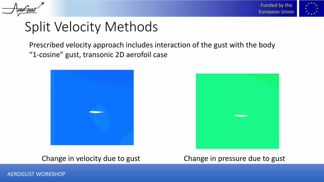
Split Velocity Methods
Change in velocity due to gust Change in pressure due to gust
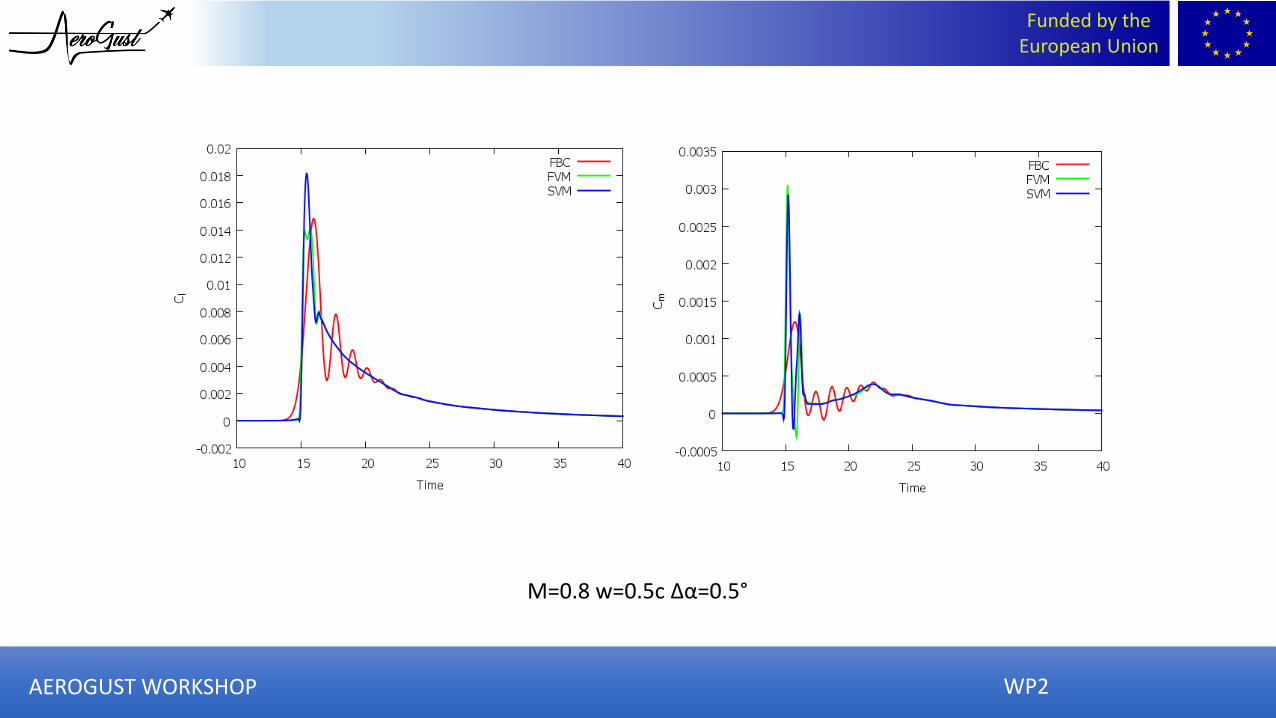
Prescribed velocity approach includes interaction of the gust with the body“1-cosine” gust, transonic 2D aerofoil case
AEROGUST WORKSHOP
Funded by the European Union
M=0.8 w=0.5c Δα=0.5°
WP2AEROGUST WORKSHOP

Funded by the European Union
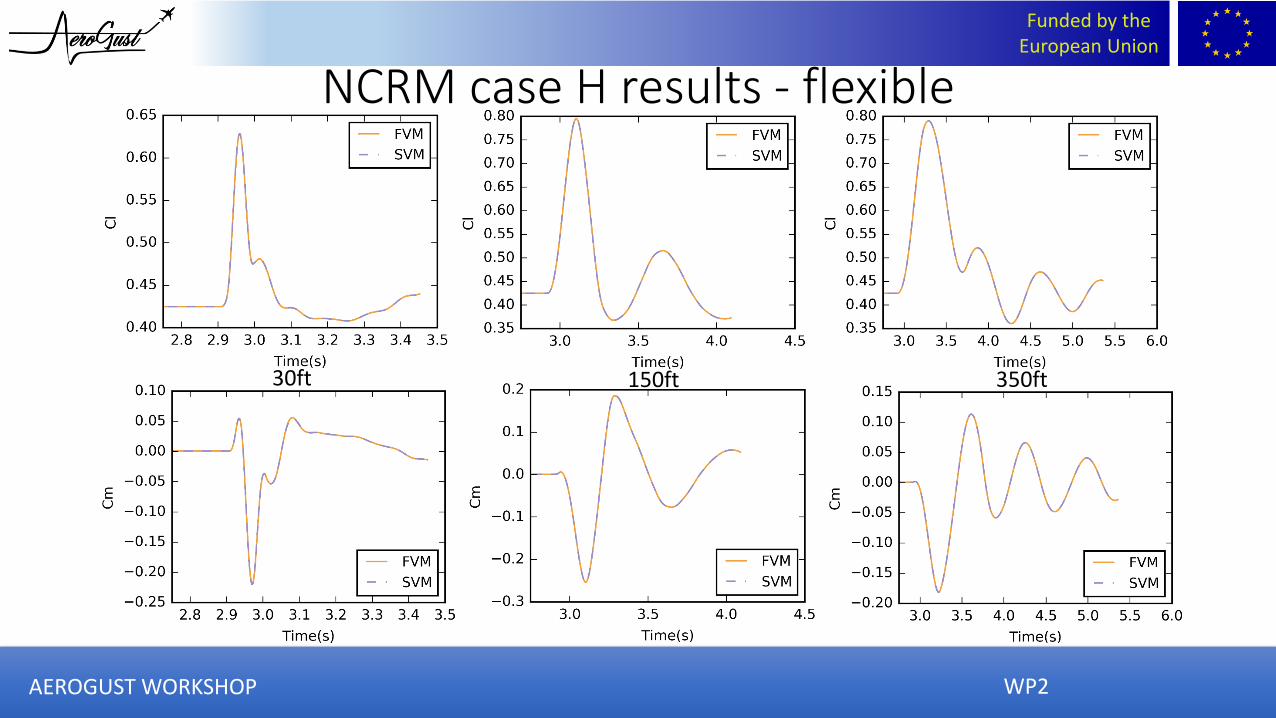
• Case H
- 29995ft, Mach 0.86
• Maximum take off mass case
Case H
Gust Length(m)
Gust velocity(m/s)
Equivalent AoA(degrees)
18.29 11.24 2.47
91.44 14.70 3.23
213.36 16.94 3.72
Gust test case definition
0
2
4
6
8
10
12
14
16
18
0 0.1 0.2 0.3 0.4 0.5 0.6 0.7 0.8 0.9
Gu
st v
elo
city
(m
/s)
Time (s)
WP3AEROGUST WORKSHOP
Funded by the European Union
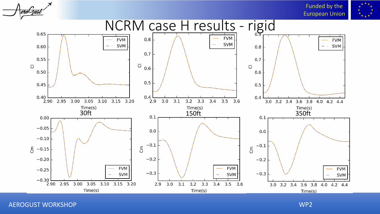
30ft 350ft150ft
WP2
NCRM case H results - rigid
AEROGUST WORKSHOP
Funded by the European Union
30ft 350ft150ft
WP2
NCRM case H results - flexible
AEROGUST WORKSHOP
Funded by the European Union
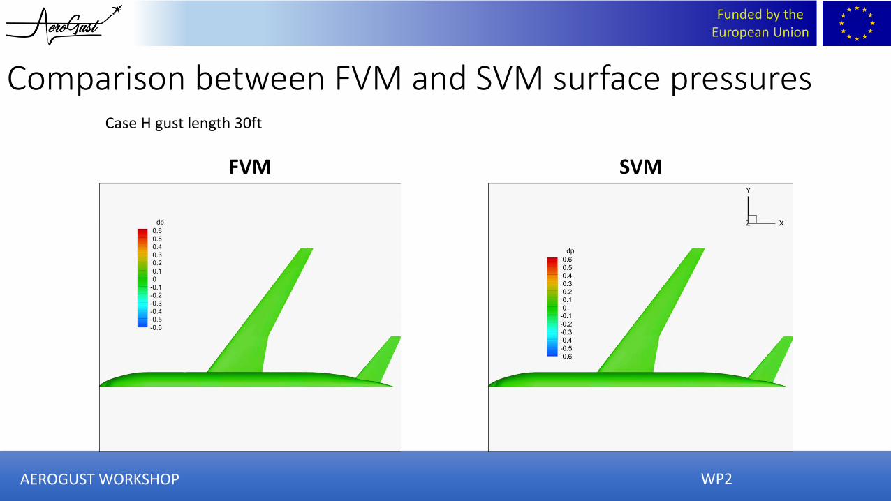
Comparison between FVM and SVM surface pressures
FVM SVM
Case H gust length 30ft
WP2AEROGUST WORKSHOP
Funded by the European Union
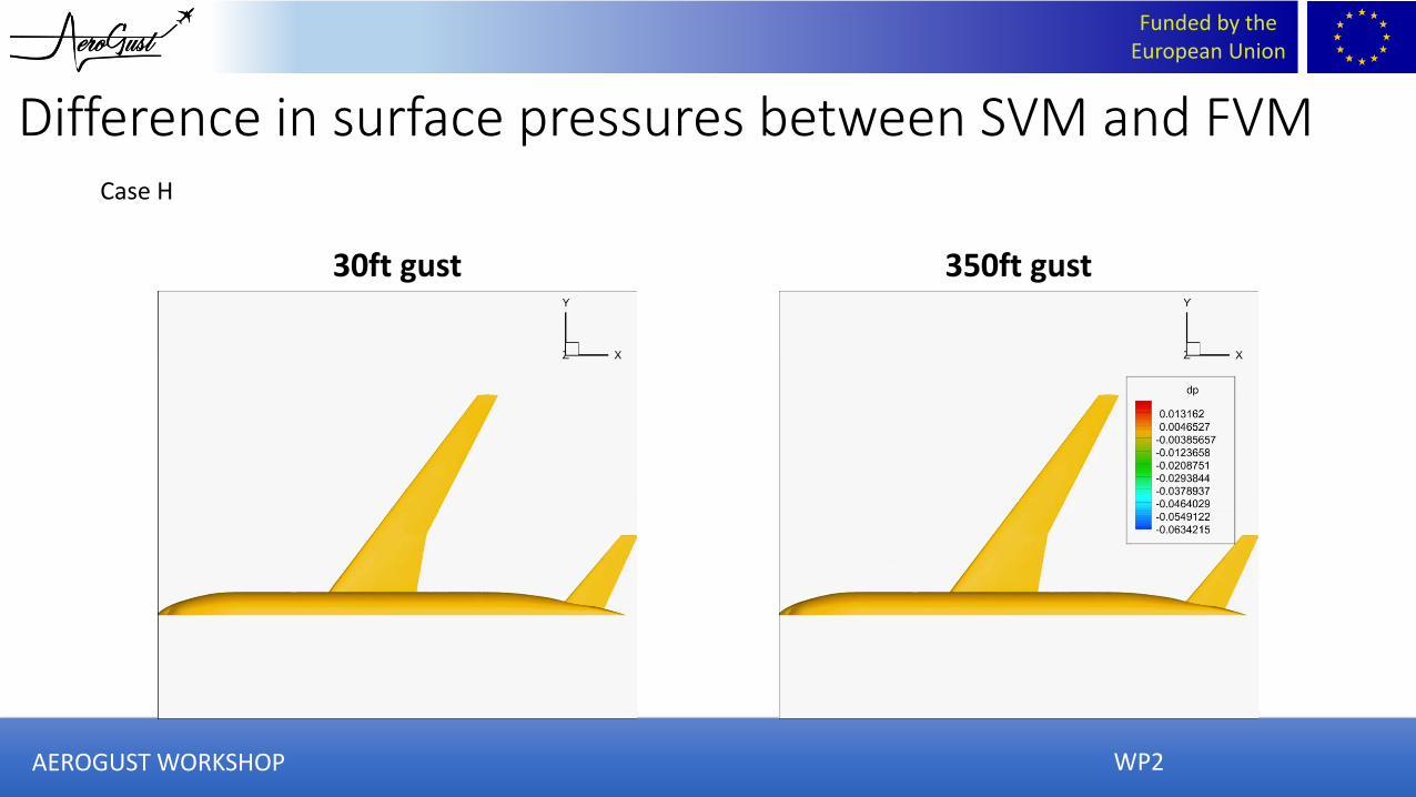
Difference in surface pressures between SVM and FVM
30ft gust 350ft gust
Case H
WP2AEROGUST WORKSHOP
Funded by the European Union
WP3
Work Package 3: Reduced reliance on wind tunnel data
“The recreation of the industrial gust loads process, using CFD in place of experimental data”
“Investigation of the underlying assumptions of the current industrial gust loads process”
AEROGUST WORKSHOP
Funded by the European Union
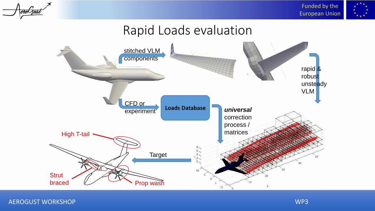
stitched VLM
components
rapid &
robust
unsteady
VLM
Loads DatabaseCFD or
experiment
Target
High T-tail
Prop wash
Strut
braced
universal
correction
process /
matrices
Rapid Loads evaluation
WP3AEROGUST WORKSHOP
Funded by the European Union
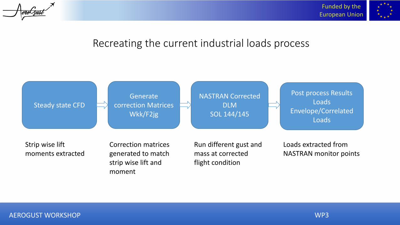
Steady state CFDNASTRAN Corrected
DLMSOL 144/145
Post process ResultsLoads
Envelope/Correlated Loads
Generate correction Matrices
Wkk/F2jg
Strip wise lift moments extracted
Correction matrices generated to match strip wise lift and moment
Run different gust and mass at corrected flight condition
Loads extracted from NASTRAN monitor points
Recreating the current industrial loads process
WP3AEROGUST WORKSHOP
Funded by the European Union
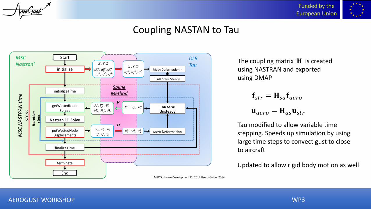
Mesh Deformation
Start
initialize Mesh Deformation -IC
TAU Solve Steady
TAU Solve
Unsteady
initializeTime
getWettedNodeForces
finalizeTime
terminate
End
MSC
NA
STR
AN
tim
e st
eps
iter
ati
on
st
eps
MSC Nastran1
DLR Tau
Spline Method
Nastran FE Solve
1 MSC Software Development Kit 2014 User's Guide. 2014.
putWettedNodeDisplacements
The coupling matrix 𝐇 is created using NASTRAN and exported using DMAP
𝐟𝑠𝑡𝑟 = 𝐇𝑠𝑎𝐟𝑎𝑒𝑟𝑜
𝐮𝑎𝑒𝑟𝑜 = 𝐇𝑎𝑠𝐮𝑠𝑡𝑟
Tau modified to allow variable time stepping. Speeds up simulation by using large time steps to convect gust to close to aircraft
Updated to allow rigid body motion as well
Coupling NASTAN to Tau
WP3AEROGUST WORKSHOP

Funded by the European Union
UVLM code• 3 Parts
• Vortex ring elements on body
• Layer of buffer panels in the wake
• Vortex particles in the wake
• Rigid body motions
• Deformations
• Gust interactions
WP3AEROGUST WORKSHOP
Funded by the European Union
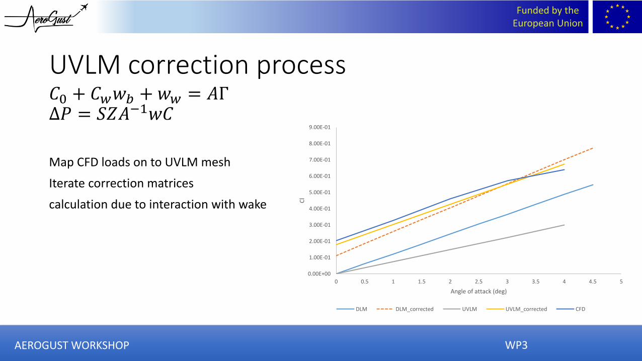
UVLM correction process𝐶0 + 𝐶𝑤𝑤𝑏 + 𝑤𝑤 = 𝐴Γ∆𝑃 = 𝑆𝑍𝐴−1𝑤𝐶
Map CFD loads on to UVLM mesh
Iterate correction matrices
calculation due to interaction with wake
WP3
0.00E+00
1.00E-01
2.00E-01
3.00E-01
4.00E-01
5.00E-01
6.00E-01
7.00E-01
8.00E-01
9.00E-01
0 0.5 1 1.5 2 2.5 3 3.5 4 4.5 5
Cl
Angle of attack (deg)
DLM DLM_corrected UVLM UVLM_corrected CFD
AEROGUST WORKSHOP
Funded by the European Union
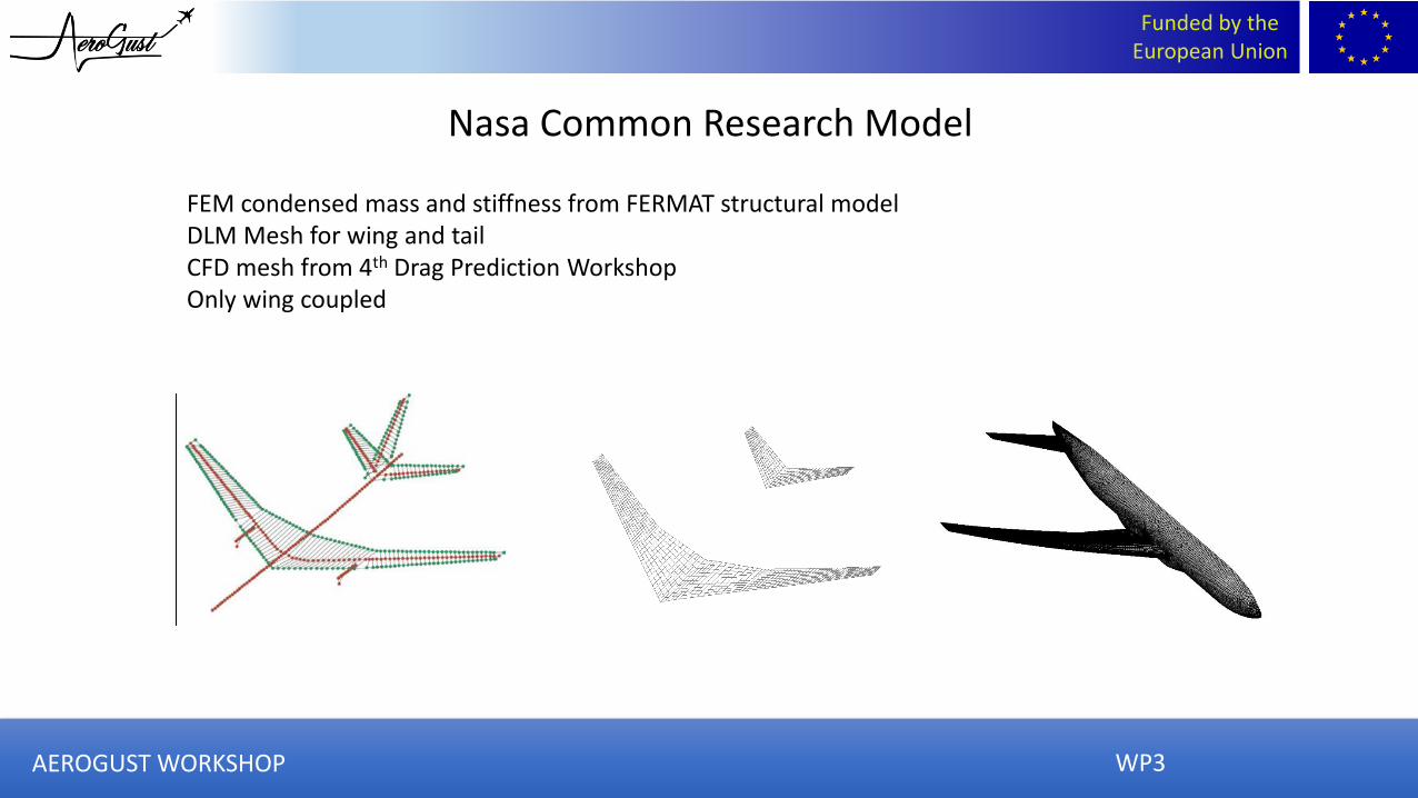
FEM condensed mass and stiffness from FERMAT structural modelDLM Mesh for wing and tailCFD mesh from 4th Drag Prediction WorkshopOnly wing coupled
Nasa Common Research Model
WP3AEROGUST WORKSHOP

Funded by the European Union
30ft350ft150ft
Corrected DLM and UVLM for rigid geometry
AEROGUST WORKSHOP

Funded by the European Union
30ft
350ft
Corrected DLM loads for flexible wing
Root shear Root bending Root torque
WP3AEROGUST WORKSHOP
Funded by the European Union
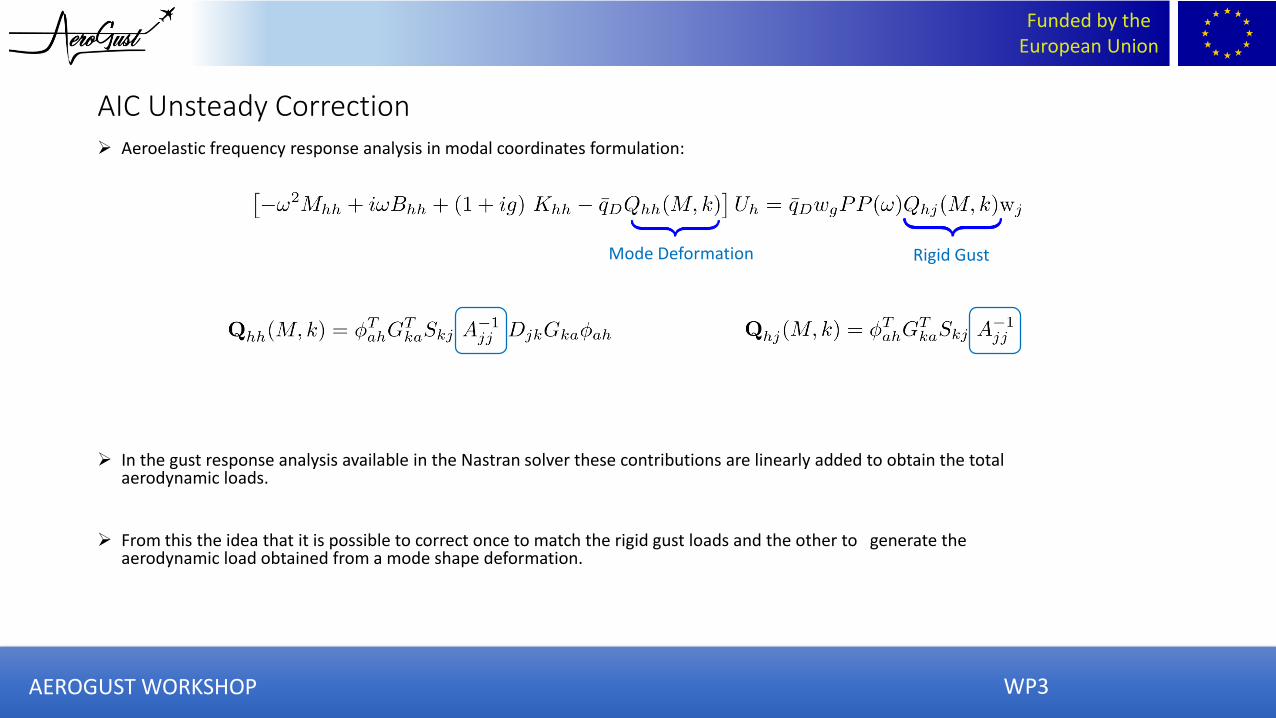
➢ Aeroelastic frequency response analysis in modal coordinates formulation:
➢ In the gust response analysis available in the Nastran solver these contributions are linearly added to obtain the total aerodynamic loads.
➢ From this the idea that it is possible to correct once to match the rigid gust loads and the other to generate the aerodynamic load obtained from a mode shape deformation.
Mode Deformation Rigid Gust
AIC Unsteady Correction
WP3AEROGUST WORKSHOP
Funded by the European Union
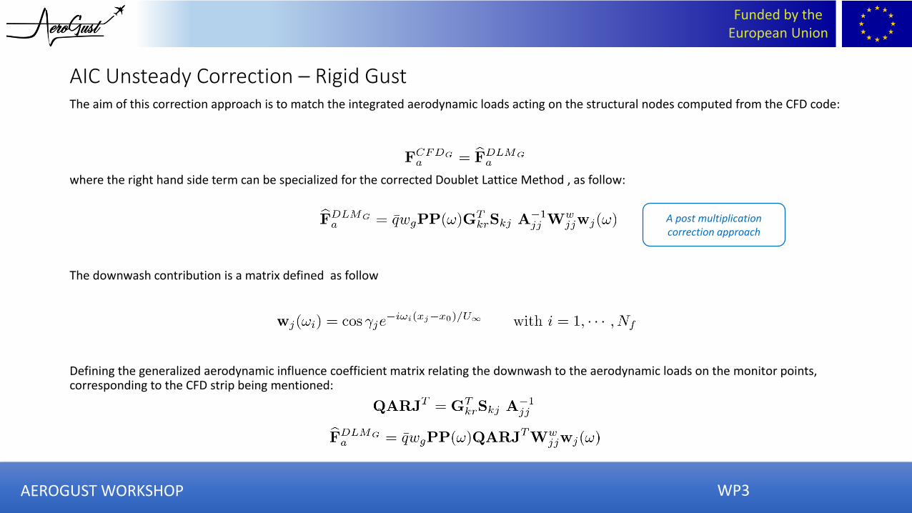
The aim of this correction approach is to match the integrated aerodynamic loads acting on the structural nodes computed from the CFD code:
where the right hand side term can be specialized for the corrected Doublet Lattice Method , as follow:
The downwash contribution is a matrix defined as follow
Defining the generalized aerodynamic influence coefficient matrix relating the downwash to the aerodynamic loads on the monitor points, corresponding to the CFD strip being mentioned:
AIC Unsteady Correction – Rigid Gust
A post multiplication correction approach
WP3AEROGUST WORKSHOP

Funded by the European Union
AIC Unsteady Correction FrameworkThe time domain CFD gust response loads has been evaluated for different reduced frequency.
For each of them the time history of the integrated loads of the ten strips along the wing has been computed.
The input signal has been chosen long enough to reach a stationary harmonic response.
At this point a reference period has been selected, and an equivalent periodic signal has been reconstructed.
To obtain comparable results to the ones computed by the DLM the Fourier Series has been used to obtain the frequency domain loads.
The correction factors have been used to update the AICs matricescomputed in the gust response analysis.
WP3AEROGUST WORKSHOP
Funded by the European Union
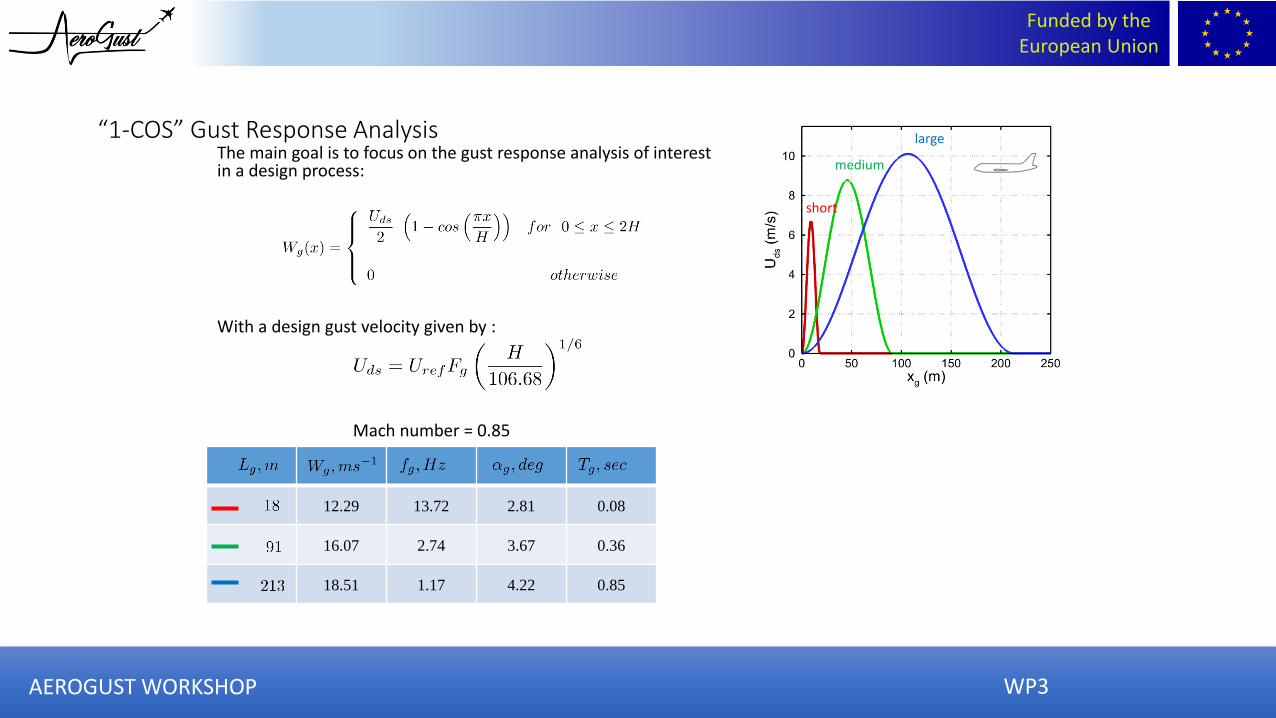
“1-COS” Gust Response Analysis
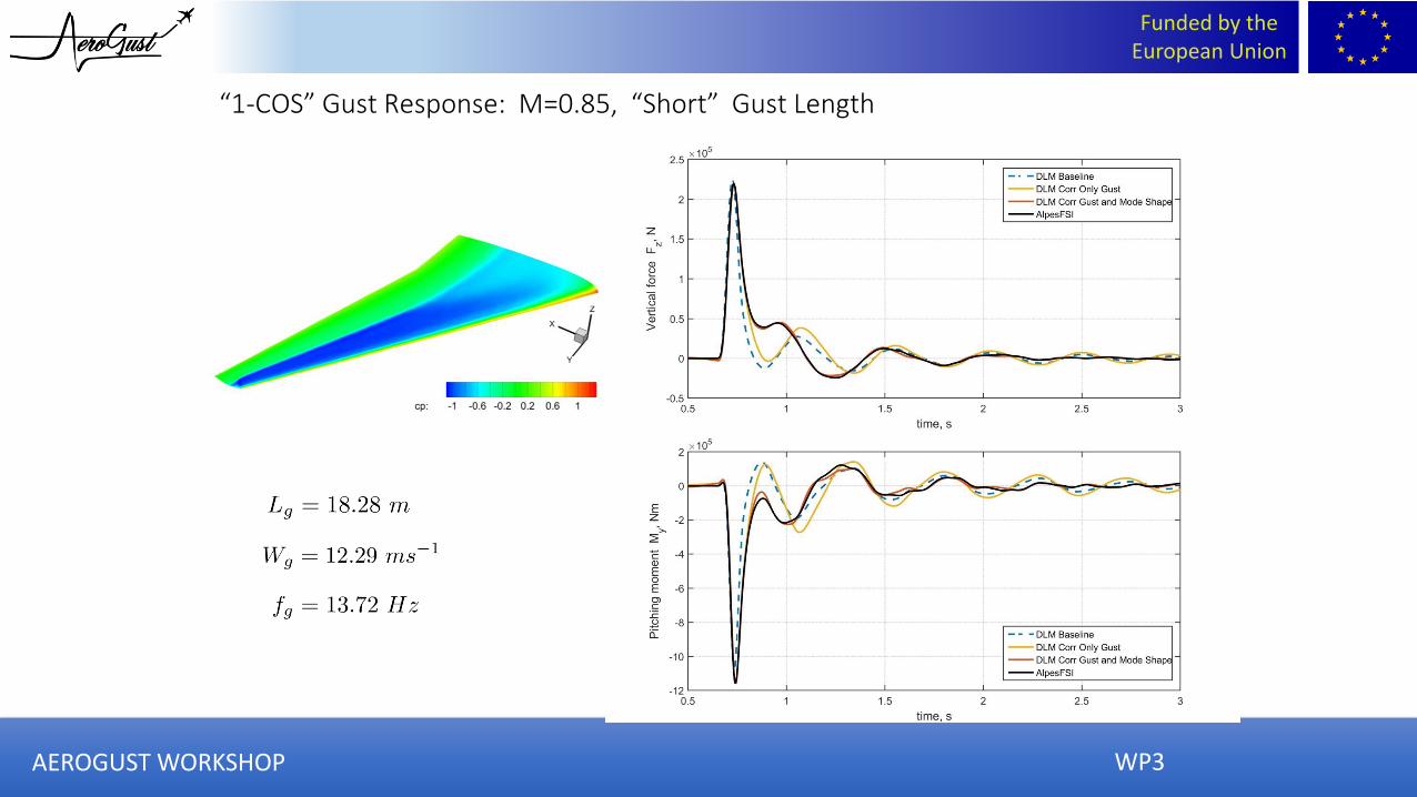
12.29 13.72 2.81 0.08
16.07 2.74 3.67 0.36
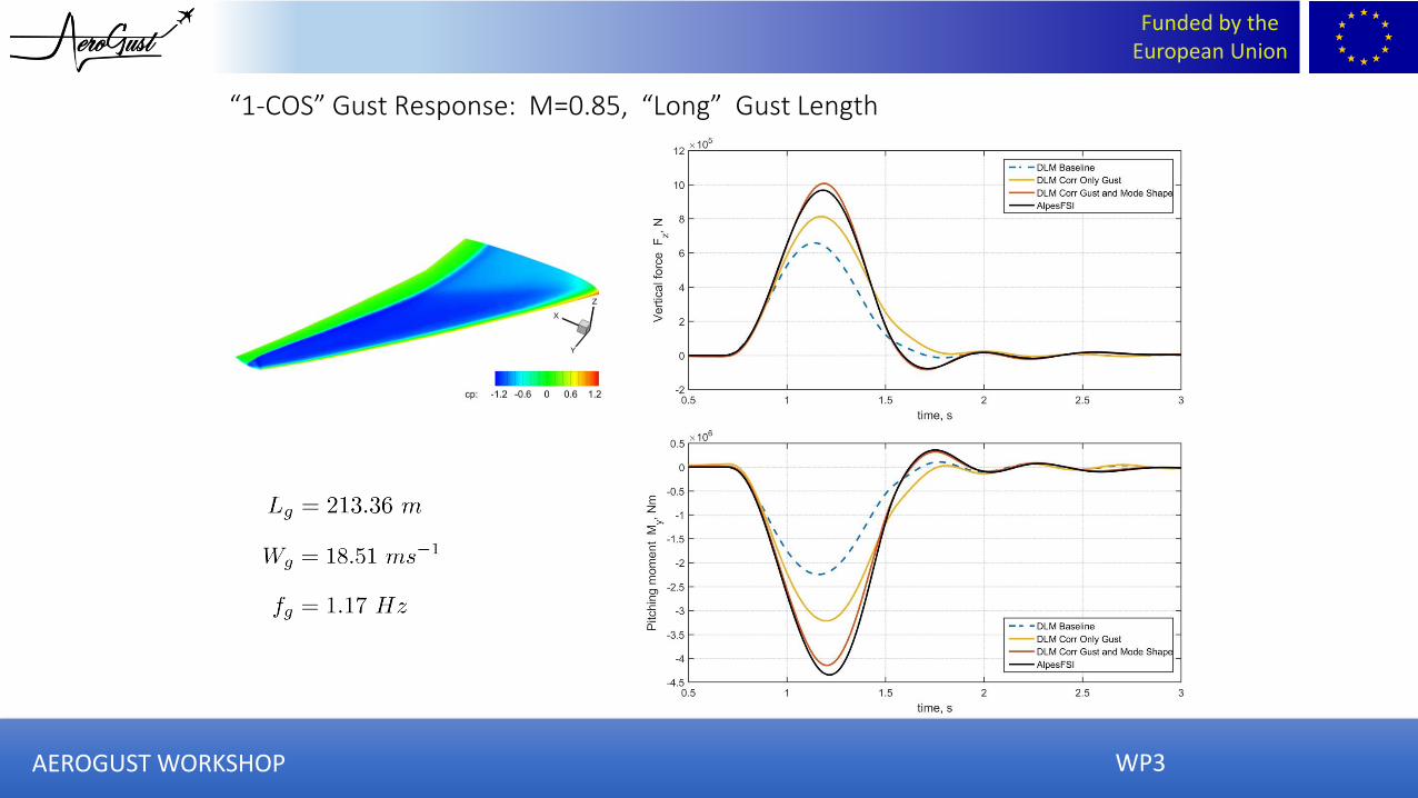
18.51 1.17 4.22 0.85
Mach number = 0.85
short
medium
largeThe main goal is to focus on the gust response analysis of interest in a design process:
With a design gust velocity given by :
WP3AEROGUST WORKSHOP
Funded by the European Union
“1-COS” Gust Response: M=0.85, “Short” Gust Length
AEROGUST WORKSHOP WP3

Funded by the European Union
“1-COS” Gust Response: M=0.85, “Medium” Gust Length
WP3AEROGUST WORKSHOP
Funded by the European Union
“1-COS” Gust Response: M=0.85, “Long” Gust Length
WP3AEROGUST WORKSHOP
Funded by the European Union
Conclusions
Next steps
• For gust lengths required for certifying “1-cosine” gust loads the FVM and SVM produce the same results• DLM and UVLM both over predict gust loads when corrected with purely steady data• Using unsteady data the accuracy of the corrected DLM can be greatly improved
• Apply improved DLM correction method to NCRM test case• Test corrected UVLM coupled to NASTRAN• Use unsteady data to improve UVLM correction
AEROGUST WORKSHOP

Funded by the European Union
AEROGUST WORKSHOP
The research leading to this work has received funding from the European Union’s Horizon 2020 research and innovation programme under grant agreement number 636053.