Embed Size (px)
Citation preview
UNIVERSITI SAINS MALAYSIA
First Semester Examination
2013/2014 Academic Session
December 2013 / January 2014
EEK 471 – ADVANCED POWER ELECTRONIC
[ELEKTRONIK KUASA LANJUTAN]
Duration 3 hours Masa : 3 jam
Please check that this examination paper consists of THIRTEEN (13) pages of printed material
before you begin the examination.
[Sila pastikan bahawa kertas peperiksaan ini mengandungi TIGA BELAS (13) muka surat
bercetak sebelum anda memulakan peperiksaan ini]
Instructions: This question paper consists SIX (6) questions. Answer FIVE (5) questions. All
questions carry the same marks.
[Arahan: Kertas soalan ini mengandungi ENAM (6) soalan. Jawab LIMA (5) soalan. Semua
soalan membawa jumlah markah yang sama]
Answer to any question must start on a new page.
[Mulakan jawapan anda untuk setiap soalan pada muka surat yang baru]
“In the event of any discrepancies, the English version shall be used”.
[Sekiranya terdapat sebarang percanggahan pada soalan peperiksaan, versi Bahasa
Inggeris hendaklah diguna pakai]
…2/-
- 2 - [EEK 471]
1. (a) Huraikan perbezaan di antara penerus 3 fasa semi kawalan dan kawalan penuh
Describe the differences between a semi controlled and a fully controlled 3 phase
rectifier
(20 markah/marks)
(b) Penerus terkawal 3 fasa digunakan untuk membekalkan kuasa ke beban induktif
tinggi dari punca AU 450 Vrms 50 Hz. Arus beban pada sisi AT ialah 20A.
galangan talian pada setiap fasa ialah 5 mH.
A three-phase fully controlled bridge rectifier is used to supply power to a highly
inductive load from a 450 Vrms 50 Hz ac supply. The load current on dc side is 20
A. The line inductance of each phase is 5 mH.
(i) Lakarkan voltan keluaran untuk sudut picuan =30o
Draw the output voltage for firing angle =30o
(30 markah/marks)
(ii) Tentukan sudut picuan α yang diperlukan untuk menghasilkan voltan
keluaran 230V
Determine the firing angle required to produce an output voltage of
230V
(30 markah/marks)
(iii) Kirakan jumlah kuasa
Calculate the total power. (20 markah/marks)
…3/-
- 3 - [EEK 471]
2. (a) Lakarkan tatarajah litar pengawal dwihala satu fasa menggunakan satu tiristor
dan 4 diod. Huraikan operasi litar dengan bantuan bentuk gelombang keadaan
malar untuk beban berperintang
Sketch the circuit diagram of a single-phase bidirectional controller with one
thyristor and four diodes. Describe operation of the circuit with the aid of key
steady state waveforms for the case of resistive load.
(20 markah/marks)
(b) Terbitkan persamaan voltan keluaran rms untuk pengawal dwihala satu fasa
seperti dalam S2(a).
Derive the expression for rms output voltage for the single-phase bidirectional
controller given in Q2(a).
(10 markah/marks)
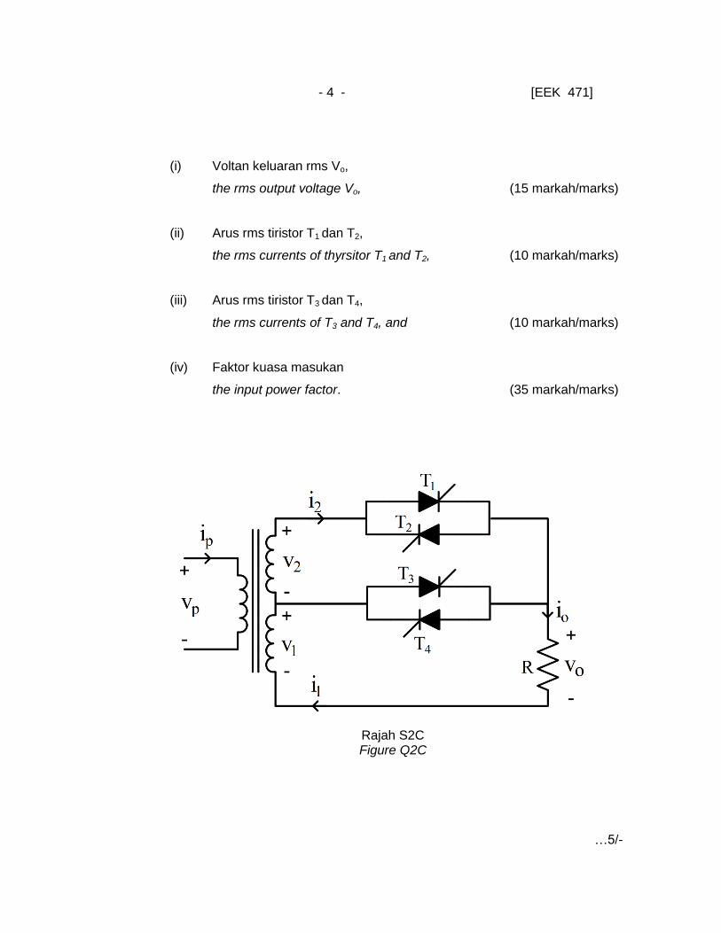
(c) Suatu transformer satu fasa penukar top (ditunjukkan oleh Rajah S2c)
membekalkan beban perintang tulin 6 Ω dari sumber AU 230 Vrms, 50 Hz. Voltan
sekunder masing-masing V1 , V2 adalah 140V dan 120 V. Sistem beroperasi
pada julat kawalan 3 [V1 Vo (V1+ V2)] dan sudut picuan tiristor T1 dan T2 ialah
90. Tentukan
A single-phase transformer tap changer (shown in Figure Q2C) is feeding a
purely resistive load of 6 Ω from an ac source of 230 Vrms 50 Hz. The secondary
voltages V1 and V2 are 140V and 120 V respectively. The system is operating in
control range 3 [V1 Vo (V1+ V2)] and firing angle of thyrsitors T1 and T2 is 90.
Determine
…4/-
- 4 - [EEK 471]
(i) Voltan keluaran rms Vo,
the rms output voltage Vo, (15 markah/marks)
(ii) Arus rms tiristor T1 dan T2,
the rms currents of thyrsitor T1 and T2, (10 markah/marks)
(iii) Arus rms tiristor T3 dan T4,
the rms currents of T3 and T4, and (10 markah/marks)
(iv) Faktor kuasa masukan
the input power factor. (35 markah/marks)
Rajah S2C Figure Q2C
…5/-

- 5 - [EEK 471]
3. (a) Dengan bantuan tatarajah litar dan bentuk gelombang keadaan malar huraikan
opearasi inverter titi-penuh satu fasa dengan keluaran gelombang segiempat
untuk beban jenis RL. Huraikan juga fungsi diod meroda bebas yang digunakan
secara balikan selari dengan suis kuasa.
With the aid of circuit diagrams and steady state waveforms explain the operation
of single-phase full-bridge inverter with square wave output for RL-type load.
Also explain the function of free-wheeling diodes used in anti-parallel with the
power switches.
(25 markah/marks)
(b) Terbitkan persamaan voltan keluaran asas rms untuk inverter gelombang
segiempat yang diberi dalam S3(a).
Derive expression for the fundamental rms output voltage for the square-wave
inverter given in Q3(a).
(27 markah/marks)
(c) Inverter PWM titi penuh satu fasa digunakan untuk membekal kuasa ac ke beban
induktif dari punca dc 250 V. Komponen perintang dan induktif beban masing-
masing mempunyai 10 dan 2mH. Inverter beroperasi pada frekuensi 50Hz dan
kitar tugas 60%. Kirakan
A single-phase full-bridge PWM inverter is used to supply ac power to an
inductive load from a dc source of 250 V. The resistive and inductive components
of the load are 10 and 20mH respectively. The inverter operates at a
frequency of 50Hz and duty cycle is 60%. Determine the following:
…6/-
- 6 - [EEK 471]
(i) Nilai rms jumlah voltan keluaran ac
The rms value of total ac output voltage. ( 4 markah/marks)
(ii) Nilai rms harmonic asas dan 2 peringkat terendah (3rd dan 5th).
The rms value of the fundamental and two lowest-order harmonics (3rd
and 5th).
(24 markah/marks)
(iii) Nilai rms jumlah komponen harminik voltan keluaran
The rms value of total harmonic component of the output voltage.
(8 markah/marks)
(iv) Jumlah Herotan Harmonik
The total harmonic distortion THD (8 markah/marks)
(v) Nisbah pindah voltan (Tvv) dari komponen asas inverter
The voltage transfer ratio (Tvv) of the fundamental component of the
inverter
. (4 markah/marks)
4. (a) Senaraikan 2 penggunaan penukar boost
List down two applications of boost converters.
(4 markah/marks)
…7/-
- 7 - [EEK 471]
(b) Lakarkan tatarajah litar penukar buck-boost dan huraikan operasinya dengan
bantuan bentuk gelombang keadaan malar menjurus ke terbitan persamaan
antara voltan masukan Vin dan voltan keluaran Vo.
Sketch circuit diagram of a buck-boost converter and describe its operation with
the aid of key steady state waveforms leading to the derivation of an expression
between input voltage Vin and output voltage Vo.
(48 markah/marks)
(c) Penukar Cuk (seperti ditunjukkan oleh Rajah 4c) digunakan untuk mengatur
kuasa AT ke beban perintang 35W dari sumber dc 50V. Nilai komponen litar:
, , , dan . Penukar beroperasi
pada frekuensi pensuisan 30 kHz dan kitar tugas D=0.60. Kirakan
A Cuk converter (shown in Figure Q4c) is used to supply regulated dc power to
resistive load of from a dc source of . The value of the circuit
components are: , , , and . The
converter operates at a switching frequency of and duty cycle .
Determine;
(i) Purata voltan keluaran Vo
the average output voltage , (5 markah/marks)
(ii) Purata arus masukan Is
the average input current , (5 markah/marks)
…8/-

- 8 - [EEK 471]
(i) Riak arus puncak ke puncak induktor dan ,
the peak to peak ripple current of inductors and ,
(10 markah/marks)
(ii) Riak voltan puncak ke puncak kapasitor , dan ,
the peak to peak ripple voltage of the capacitors , and ,
(10 markah/marks)
(iii) Arus puncak transistor Ip
the peak current of the transistor . (18 markah/marks)
Rajah S4c Figure Q4c
…9/-

- 9 - [EEK 471]
5. (a) Lakar tatarajah litar inverter titi penuh salunan siri yang terdiri dari suis dwi hala
dan huraikan operasinya untuk mod tindihan lampau?
Sketch circuit diagram of a full-bridge series resonant inverter with bidirectional
switches and describe its operation for overlapping mode of operation?
(20 markah/marks)
(b) Untuk litar salunan siri berbeban dari S5(a), terbitkan persamaan yang
menghubungkan gandaan voltan litar dan frekuensi pensuisan.
For the series loaded resonant circuit given in Q5(a), derive an expression that
relates the voltage gain of the circuit with its switching frequency.
(20 markah/marks)
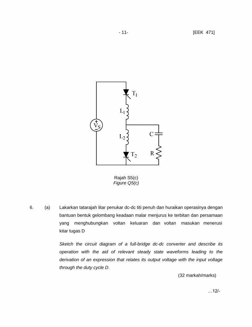
(c) Inverter salunan siri digunakan untuk membekalkan kuasa ac ke beban perintang
dari sumber dc seperti ditunjukkan oleh Rajah S5(c). Voltan masukan ke inverter
ialah 200V dan frekuensi pensuisan ialah 5 kHz. Nilai komponen litar:
HLL 5021 , FC 5 and 5R . Nilai masa buka tiristor yang digunakan
dalam litar ialah Stq 9 . Dari sistem ini kirakan parameter berikut:
A series resonant inverter is used to supply ac power to a resistive load from a dc
source as shown in Figure Q5C. The input dc voltage to the inverter is 200 V
and its switching frequency is 5 kHz. The values of other circuit components are:
HLL 5021 , FC 5 and 5R . The turn of time of the thryistors that
are used in the circuit is Stq 9 . Evaluate the following parameters of the
system
…10/-
- 10 - [EEK 471]
(i) Faktor anjalan dan frekuensi salunan rf
the damping factor and resonant frequency rf ,
(6 markah/marks)
(ii) Masa tutup offt ,
the available turn off time offt , (4 markah/marks)
(iii) Frekuensi maksimum yang dibenarkan maxf ,
the maximum permissible frequency maxf , (4 markah/marks)
(iv) Voltan puncak ke puncak kapasitor Vpp
the peak to peak capacitor voltage ppV , (28 markah/marks)
(v) Arus beban puncak Ipeak
the peak load current peakI . (18 markah/marks)
…11/-
- 11- [EEK 471]
Rajah S5(c) Figure Q5(c)
6. (a) Lakarkan tatarajah litar penukar dc-dc titi penuh dan huraikan operasinya dengan
bantuan bentuk gelombang keadaan malar menjurus ke terbitan dan persamaan
yang menghubungkan voltan keluaran dan voltan masukan menerusi
kitar tugas D
Sketch the circuit diagram of a full-bridge dc-dc converter and describe its
operation with the aid of relevant steady state waveforms leading to the
derivation of an expression that relates its output voltage with the input voltage
through the duty cycle D.
(32 markah/marks)
…12/-
- 12- [EEK 471]
(b) Penukar tolak-tarik dari Rajah S6b menghasilkan voltan keluaran Vo= 45 V
merentasi beban perintang 2 apabila beroperasi pada kitar tugas 0.5.
Kejatuhan voltan keadaan bukadan diod adalahmasing-masing 1.2 V dan 0.7 V.
Nisbah pusingan pengubah ialah a=Ns/Np=0.25. Abaikan kehilangan dalam
pengubah, arus riak beban dan sumber masukan. Tentukan:
The push-pull converter of Figure Q6b produces an output voltage Vo= 45 V
across a resistive load of 2 when operating at a duty cycle of 0.5. The on-
state voltage drop of transistors and diodes are 1.2 V and 0.7 V, respectively.
The turn ratio of the transformer is a=Ns/Np=0.25. Neglect the losses in the
transformer and the ripple current of the load and input supply is negligible.
Determine
(i) Purata arus masukan Is
The average input current IS, (20 markah/marks)
(ii) Kecekapan η
The efficiency η, (8 markah/marks)
(iii) Purata arus (IA), arus rms (Irms) dan arus puncak transistor (Ip)
The average current (IA), rms current (Irms) and peak transistor current (IP)
(12 markah/marks)
(iv) Voltan transistor litar terbuka
The open circuit transistor voltage. (4 markah/marks)
…13/-

- 13- [EEK 471]
(c) Lakarkan tatarajah litar pembekal kuasa ac mod salunan dan dwihala
Draw the circuit diagrams of resonant mode ac power supply and bidirectional ac
power supply.
(24 markah/marks)
Rajah S6(b)
Figure Q6(b)
ooo0ooo