Embed Size (px)
Citation preview

1
ANTENNA DESIGN AND MEASUREMENT TECHNIQUES - Madrid (UPM) – March 2012
Array antennas introduction
José Manuel Inclán Alonso
Universidad Politécnica de Madrid
(Technical University of Madrid, UPM)
ANTENNA DESIGN AND MEASUREMENT TECHNIQUES - Madrid (UPM) – March 2012
Outline
2
• Array antennas definition
• Arrays types
• Depending on its elements
• Depending on it application
• Depending on the geometry
• Depending on the network
• Arrays theory
• Radiation pattern of an array
• Multiplication patterns principle
• Equispace linear arrays
• Effects of the feeding elements

2
ANTENNA DESIGN AND MEASUREMENT TECHNIQUES - Madrid (UPM) – March 2012
Array antenna definition
3
ANTENNA DESIGN AND MEASUREMENT TECHNIQUES - Madrid (UPM) – March 2012
What is an array antenna?
4
• Definition:
• An array antenna is a spatially extended collection of N similar radiating elements, and
the term "similar radiating elements" means that all the elements have the same
radiation patterns, orientated in the same direction in 3D space.
• The elements don't have to be necessary spaced on a regular grid, but it is assumed
that they are all fed with the same frequency.
– Group of individual radiating elements
– Feed from a common terminal
– By linear networks
3
ANTENNA DESIGN AND MEASUREMENT TECHNIQUES - Madrid (UPM) – March 2012
Array types
5
ANTENNA DESIGN AND MEASUREMENT TECHNIQUES - Madrid (UPM) – March 2012
• Depending on its elements
– Wires → wire array antennas
– Printed elements → printed array antennas
– Slot → slot array antennas
– Horn → horn array antennas
Arrays types: elements
4
ANTENNA DESIGN AND MEASUREMENT TECHNIQUES - Madrid (UPM) – March 2012
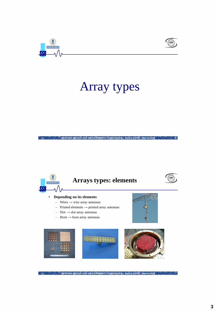
Radiating elements used to form arrays
Dipole
Helix
Monopole
Slots
Patch
Horn
ANTENNA DESIGN AND MEASUREMENT TECHNIQUES - Madrid (UPM) – March 2012
Radiating elements used to form arrays (II)

5
ANTENNA DESIGN AND MEASUREMENT TECHNIQUES - Madrid (UPM) – March 2012
Arrays types: application
• Depending on it application
– Communications
• mobile
• Satellite
– Radar
– …
ANTENNA DESIGN AND MEASUREMENT TECHNIQUES - Madrid (UPM) – March 2012
Arrays types: geometry (I)
• Depending on it geometry
– Linear
– Planar
– Conformal
» Cylindrical
» Spherical
This classification depends on the position where the different elements are
placed:
Linear (elements in a line)
Planar (elements in a plane): rectangular (elements in a rectangular shape),
triangular (elements in a triangle shape, circular (elements on concentric
circumferences)
Conformal (elements in a 3D-surface): cylinder, sphere...

6
ANTENNA DESIGN AND MEASUREMENT TECHNIQUES - Madrid (UPM) – March 2012
Arrays types: geometry (II) Examples of linear arrays
Base station antennas for
mobile systems
application: DECT (3.5
GHz): Vertical 65°, 90°
antennas
Base station antennas
for mobile systems
applications: GSM 1800
MHz: Vertical pol.°
sectorial 65° & 90°
antennas
Base station antennas
for mobile systems
applications: UMTS:
crosspolar ± 45°
sectorial 65° antennas
The printed antennas have the advantage to be easy to
fabricate and low cost
ANTENNA DESIGN AND MEASUREMENT TECHNIQUES - Madrid (UPM) – March 2012
Arrays types: geometry (III) Examples of planar arrays
• Satcom antenna
-airborne radar technology for
satellite communications
placed on the F16
• Cobra Dane
– A big antenna formed of 34769 radiating elements
– works at 1200 MHz
– part of the security radar in USA

7
ANTENNA DESIGN AND MEASUREMENT TECHNIQUES - Madrid (UPM) – March 2012
Arrays types: geometry (IV) Examples of conformal
arrays • Radiating elements placed on a no planar surface (for example curve)
• Cylindrical (Elements placed over a cylinder)
• Conical (Elements placed over a cone)
• Spherical (Elements placed on a sphere)
• Different surfaces ( flight wings, vehicle, etc.)
Example: Cylindrical array of slots
Omnidirectional Circularly Polarized
Slot Antenna Fed by a Cylindrical
Waveguide for Identification Friend
or Foe System in the 37GHz band
Electronic Radar with Conformal
Antenna (ERAKO) for avionics
Example of an antenna placed in a
missile
ANTENNA DESIGN AND MEASUREMENT TECHNIQUES - Madrid (UPM) – March 2012
• Depending on the network
– Passive
» A single beam
» Multibeam
– Active
– Adaptative
Arrays types: network (I)

8
ANTENNA DESIGN AND MEASUREMENT TECHNIQUES - Madrid (UPM) – March 2012 15
Arrays types: network (II) Pasive arrays
• Use a feeding network with passives elements (power divider, transmission lines, matching network etc.)
– The radiation pattern and polarization are fixed.
– Work as a unique antenna.
– Depending on the network
» A single beam
» multibeam
– Can have different input terminals in the network (multi-diagram or multibeam antenna).
– Are reciprocal, works in transmission and reception.
ANTENNA DESIGN AND MEASUREMENT TECHNIQUES - Madrid (UPM) – March 2012 16
• Linear active network to feed the arrays
– Allow amplified distribution in the antenna
– Allow active control of the excitations and of the radiation patterns.
– Allow signal processing
The active arrays are antennas with variable phase, that allow beam steering in a variable
direction (very useful in Radar systems).
Arrays types: network (III) Active arrays
Dis
trib
uti
on
ne
two
rk
Phase
Shifter Amplifier
Phase
Shifter Amplifier
. . .
Phase
Shifter Amplifier
Down-Up
converter
9
ANTENNA DESIGN AND MEASUREMENT TECHNIQUES - Madrid (UPM) – March 2012 17
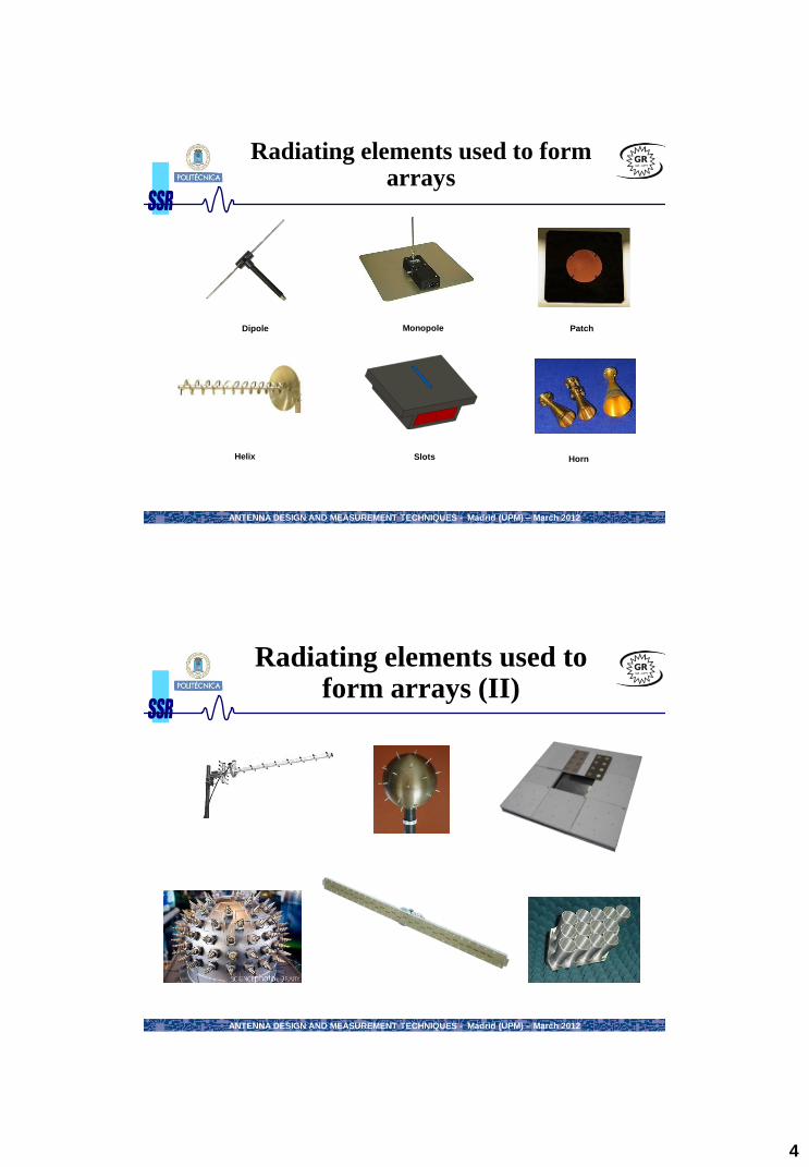
• A digital processor allow:
– Digital control of patterns
– Patterns dependent on
» frequency
» time
» code
– Simultaneous variables patterns
The adaptative arrays are kind of antennas that works with active feeding modifying
instantaneously the radiation pattern depending on the signal that it receives (These antennas are
very useful in communication systems)
Arrays types: network (IV) Adaptative arrays
Dig
ita
l s
ign
al
pro
ce
ss
or Amplifier
Amplifier
. . .
Amplifier
Down-Up
converter
Down-Up
converter
Down-Up
converter
A/D
A/D
A/D
ANTENNA DESIGN AND MEASUREMENT TECHNIQUES - Madrid (UPM) – March 2012 18
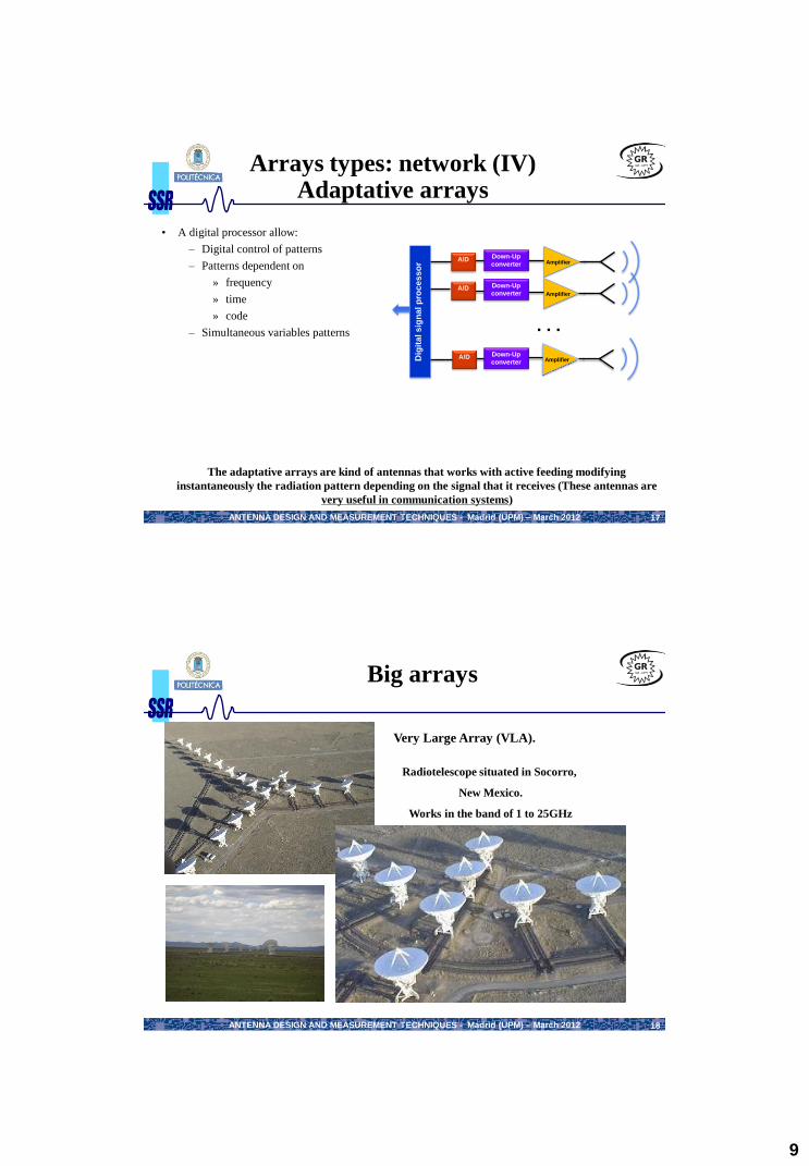
Big arrays
Very Large Array (VLA).
Radiotelescope situated in Socorro,
New Mexico.
Works in the band of 1 to 25GHz
10
ANTENNA DESIGN AND MEASUREMENT TECHNIQUES - Madrid (UPM) – March 2012
Array theory
19
ANTENNA DESIGN AND MEASUREMENT TECHNIQUES - Madrid (UPM) – March 2012 20
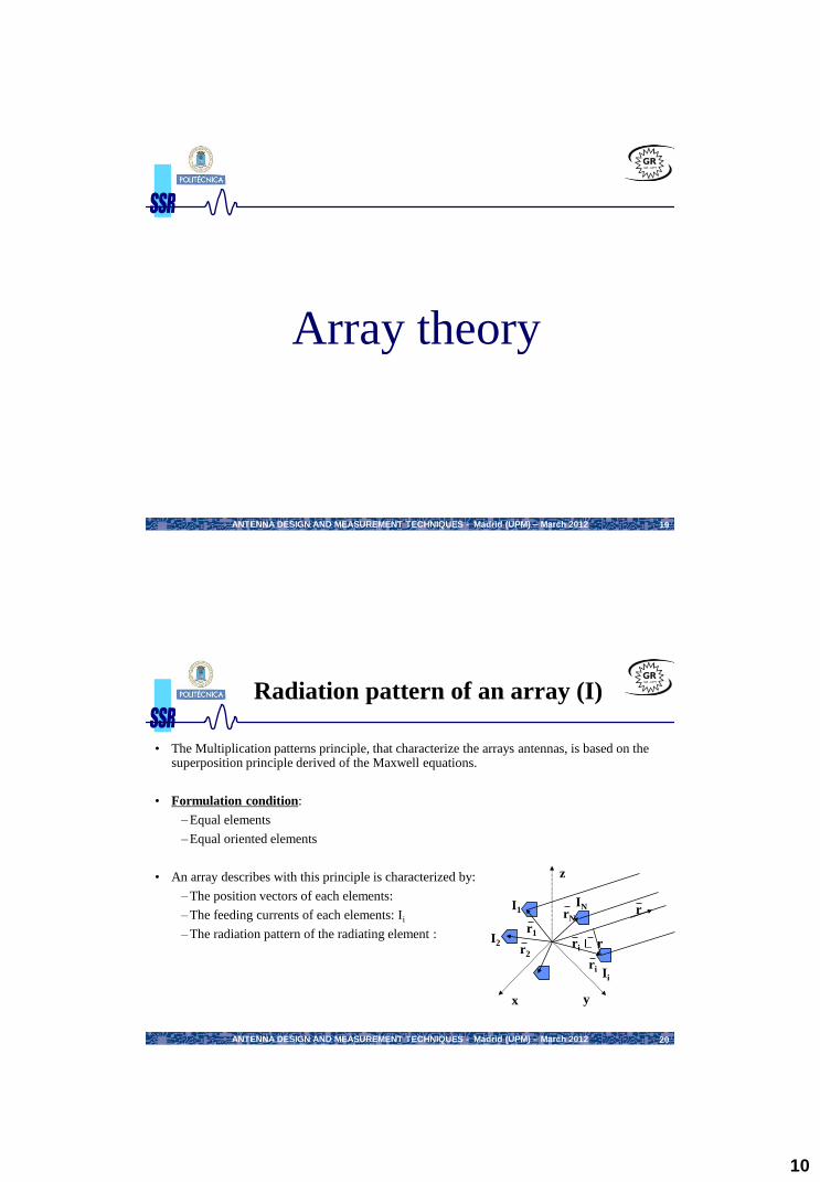
Radiation pattern of an array (I)
• The Multiplication patterns principle, that characterize the arrays antennas, is based on the superposition principle derived of the Maxwell equations.
• Formulation condition:
– Equal elements
– Equal oriented elements
• An array describes with this principle is characterized by:
– The position vectors of each elements:
– The feeding currents of each elements: Ii
– The radiation pattern of the radiating element :
x y
z
r2
r1
rN r
ri r
ri
I1
I2
IN
Ii

11
ANTENNA DESIGN AND MEASUREMENT TECHNIQUES - Madrid (UPM) – March 2012 21
Radiation pattern of an array (II)
0 ˆ, ijk rr
A iF Ae
The radiated field can be expressed as the product of the element field,
situated in the origin, by the ARRAY FACTOR FA(,).
• Radiated field for one element:
x y
z
r2
r1
rN r
ri r
ri
I1
I2
IN
Ii
In function of:
Element positions
Excitation Ai
Frequency
0 ˆ
0
, , , , ijk rrii e
IE r E r e
I
Radiated field of an
radiating element
in the origin
Complex feeding
coefficient
Relative phase for
displacement out
of the origin
, , , , ,A e AE r E r F
ANTENNA DESIGN AND MEASUREMENT TECHNIQUES - Madrid (UPM) – March 2012 22
Multiplication patterns principle (I)
• The radiation pattern of an array is the product of the radiation pattern of the single
radiating element and the array factor.
•The total radiated field polarization depends only on the used radiating element (FA is a
scalar value).
• The array factor allow to analyze how is the influence of the geometry and the feeding
on the radiation without considering what kind of radiating element we use.
•In big arrays, FA() varies more than Ee() does, and we can approximate the total
radiation pattern as the array factor.
),(),,(),,( AeA FrErE

12
ANTENNA DESIGN AND MEASUREMENT TECHNIQUES - Madrid (UPM) – March 2012 23
• Example:
Multiplication patterns principle (II)
Theta
(degree)
Theta
(degree) Theta
(degree)
Element radiation pattern Ee Array Factor FA Array radiation pattern EA
),(),,(),,( AeA FrErE
ANTENNA DESIGN AND MEASUREMENT TECHNIQUES - Madrid (UPM) – March 2012 24
Equispace linear arrays (I)
• Array of N elements separated of a distance d and feed with An coefficients
•As we can see in this expression, the array factor FA is the DFT of the excitation law of the array.
•While in signal processing we pass from time domain to frequency spectrum, in arrays theory we pass from
spatial domain (position and excitation law) to angular spectrum (radiation pattern).
• Thus, all concepts of digital signal can be applied. For instance in digital signals to prevent the leakage
windowing is used, in arrays to reduce side lobes also a windowing of the feedings is used
0 0ˆ cos, njnk rr jnk d jn
A n n n
n n n
F A e A e A e
1 !!nDFT A
ˆˆ, cosn nr ndz r r nd
0 ˆ, njk rr
A nF A e jn
n nA a e
coskd
00
1 1 1coscos
0 0 0
,N N N
jn k djnk d jn
A n n n
n n n
F A e a e a e

13
ANTENNA DESIGN AND MEASUREMENT TECHNIQUES - Madrid (UPM) – March 2012 25
• Array of N elements separated of a distance d and feed with An coefficients
ˆˆ, cosn nr ndz r r nd
0 ˆ, njk rr
A nF A e jn
n nA a e
coskd
00
1 1 1coscos
0 0 0
,N N N
jn k djnk d jn
A n n n
n n n
F A e a e a e
Excitation laws most used:
Uniform in amplitude and phase, An = 1 n
Uniform in amplitude and the phase is progressive
Symmetry amplitude and decreasing from centre to edge and the phase is constant or progressive
Radiating elements with progressive phase:
= difference phase between 2 elements
Equispace linear arrays (II)
ANTENNA DESIGN AND MEASUREMENT TECHNIQUES - Madrid (UPM) – March 2012 26
• The arrays are divided depending on it steering direction in these followings types:
Broadside array : has it radiation maximum in the perpendicular plane of the array.
Exploration array: steer at a variable direction max fixed by the difference constant phase . The visible margin is the general one:
Endfire array: has the radiation maximum in the array axis (max = 0 or ).
0 max max
0
cos 0 arccosk dk d
Linear arrays uniformly feed in amplitude and the phase is progressive (III)
30
210
60
240
90
270
120
300
150
330
180 0
θ=90º 30
210
60
240
90
270
120
300
150
330
180 0
θ=70º 30
210
60
240
90
270
120
300
150
330
180 0
θ=0º

14
ANTENNA DESIGN AND MEASUREMENT TECHNIQUES - Madrid (UPM) – March 2012 27
Broadside array
-2 0 0
0.2
0.4
0.6
0.8
1
2 -
d=/2
d=
d=0.75
Uniform feeding in amplitude and phase: The visible margin is
Maximum: 20 max
ANTENNA DESIGN AND MEASUREMENT TECHNIQUES - Madrid (UPM) – March 2012 28
Exploration array
Exploration array: steer at a variable direction max fixed by the difference constant phase .
0 max max
0
cos 0 arccosk dk d
10 º 20 º 30 º 40 º

15
ANTENNA DESIGN AND MEASUREMENT TECHNIQUES - Madrid (UPM) – March 2012 29
Endfire array
The endfire array is characterized to achieve a pencil beam type main lobe
Depending on the array axis:
Main maximum: =0 or (=)
30
210
60
240
90
270
120
300
150
330
180 0
ANTENNA DESIGN AND MEASUREMENT TECHNIQUES - Madrid (UPM) – March 2012 30
Resume: Equispace linear array uniformly feed in amplitude and the phase is progresive
kd cos
• FA() is always a periodic function with period =2: the valid margin of
the radiation pattern is the margin with possible values of : between 0 y
Graphic
representation
Exploration Endfire – Phase:
– Visible
margin: – Maximum: 20 max
kd cosUniform phase
Progressive phase
kd kd
0 max
kdacos
d2kd
0kd0,0
4 0 d
maxmax o0
ji
iA eAF ),(
0 kd cos
Broadside
kd kd

16
ANTENNA DESIGN AND MEASUREMENT TECHNIQUES - Madrid (UPM) – March 2012 31
Linear arrays with symmetry amplitude, decreasing from centre to edge and the phase is constant or progressive
• With a phase variation , we can control the steering direction.
• So with an amplitude variation, we can control the side lobe levels (SLL).
• With symmetry amplitude, decreasing from centre to edge, it achieve to reduce the side lobe lels (SLL) and wider the main lobe and therefore reduce the array directivity.
• The side lobe levels (SLL) reduction achieve with symmetry amplitude, decreasing from centre to edge is equivalent to the problems of signal theory when we use no rectangular windows like (Hanning, Hamming, Triangular,…).
• As in signal theory, the side lobe levels (SLL) reduction have resolution loss that is equivalent to wider beamwidth.
ANTENNA DESIGN AND MEASUREMENT TECHNIQUES - Madrid (UPM) – March 2012 32
Control of side lobe levels (SLL)
• We observe the potential of the design that is in the arrays theory: we can control the side lobe
levels (SLL), control the steering direction,…
•With symmetry amplitude, decreasing from centre to edge, we achieve to reduce the side lobe
levels and wider the main lobe so the directivity D0 is reduced.
•Some examples for a broadside array of 5 isotropic elements separated of /2.
As we can observe the maximum directivity is given by the uniform excitation
The minimum side lobe levels (SLL) is given by the binomial feeding, with a strong reduce
directivity
If a progressive phase shift is introduced, the side lobe levels (SLL) are maintained when
the beam explore.
z

17
ANTENNA DESIGN AND MEASUREMENT TECHNIQUES - Madrid (UPM) – March 2012 33
0 20 40 60 80 100 120 140 160 180 -50
-45
-40
-35
-30
-25
-20
-15
-10
-5
0 13.4dB
-5 -4 -3 -2 -1 0 1 2 3 4 5 0
0.1
0.2
0.3
0.4
0.5
0.6
0.7
0.8
0.9
1 1
Ai=1
N=20
d=/2
DFT-1
Effect of the feeding elements (I)
• Uniform feeding: when for i=0 to N-1 1 jn
nA e
Control of steering direction
The directivity is maximum D = N for d = /2
The side lobe levels (SLL) is -13.4dB for N high
BW-3dB = 0.88/Nd sin
ANTENNA DESIGN AND MEASUREMENT TECHNIQUES - Madrid (UPM) – March 2012 34
Effect of the feeding elements (II)
• Triangular feeding: when An=[1-abs(-(n-1)/2+i)/(n/2))] ; for n=0 to i-1
N=20
d=/2
The side lobe levels (SLL) fall until -26.8dB
The directivity fall to ¾ of the maximum D = 3N/4 for d = /2
BW-3dB = 1.75/Nd sin
0 20 40 60 80 100 120 140 160 180 -50
-45
-40
-35
-30
-25
-20
-15
-10
-5
0
26.8dB
-5 -4 -3 -2 -1 0 1 2 3 4 5 0
0.1
0.2
0.3
0.4
0.5
0.6
0.7
0.8
0.9
1
DFT-1

18
ANTENNA DESIGN AND MEASUREMENT TECHNIQUES - Madrid (UPM) – March 2012 35
Effect of the feeding elements (III)
• Cosines feeding on pedestal:
for i=0 to n-1
0 20 40 60 80 100 120 140 160 180 -50
-45
-40
-35
-30
-25
-20
-15
-10
-5
0
-5 -4 -3 -2 -1 0 1 2 3 4 5 0
0.1
0.2
0.3
0.4
0.5
0.6
0.7
0.8
0.9
1
22dB
N=20
d=/2
H=0.5
Control the reduced side lobe levels (SLL)
The directivity is reduced
The beamwidth increase
DFT-1
ANTENNA DESIGN AND MEASUREMENT TECHNIQUES - Madrid (UPM) – March 2012 36
Effect of the feeding elements
• Binomial feeding: when
for i=0 to N-1
0 20 40 60 80 100 120 140 160 180 -50
-45
-40
-35
-30
-25
-20
-15
-10
-5
0
-5 -4 -3 -2 -1 0 1 2 3 4 5 0
0.1
0.2
0.3
0.4
0.5
0.6
0.7
0.8
0.9
1 without
lobes
N=20
d=/2
The side lobe levels (SLL) disappear
The directivity is reduced
The main beamwidth increase
DFT-1