Embed Size (px)
Citation preview

1
© 2017 Kolpin Outdoors Inc. REV 00
Universal UTV Rear View Mirror
Product Instructions | Part No: 98300
Kit contents:
2
1
4
3
5
9
11
12
8
13
6
Item Qty Part Description
1 1 Rearview Mirror Assembly, Center
2 1 Threaded Ball Stud
3 1 Arm Clamp Back
4 1 Arm Clamp Front
5 1 Thumb Screw
6 1 Hex Locknut, Zinc Plated, M6-1.0
7 1 Flat Mount Bracket
8 1 Bottom Tube Plastic Clamp
9 1 Top Tube Metal Clamp
10 2 Socket Screw, Zinc Plated, M6-1.0 x 40mm LG
11 2 Locknut, Zinc Plated, #8-32
12 2 Pan Screw, Zinc Plated, #8-32 x 0.5in LG
13 2 Thread Forming Screw for Plastic Clamp
Before you begin, read these instructions and check to be sure all parts and tools are accounted for. Please retain these installation
instructions for future reference and parts ordering information. Note: If any hardware is missing, do not return to the
store. Call us to help, Toll Free 1-877-956-5746.
7 10
Kolpin Outdoors, Inc. | 9955 59th Ave N | Plymouth, MN 55442
(877) 956-5746 or (763) 478-5800 | www.kolpin.com | [email protected]
This mirror is designed to quickly and
easily universal mount to any tubular bar,
specifically UTV roll cages, or flat drillable
surfaces. The kit fits tubing sizes from
1-1/2” to 2.0” in diameter. The clamp can
be used in the vertical and horizontal
positions. The double ball joint is easy to
adjust and increases viewing positions.
Note, installation may be easier if
certain items are removed from vehicle
first.
Tools and Supplies Required
• 5mm Hex Allen Wrench or Socket Bit
• T20 Bit Screwdriver
• 11/32” Wrench or Socket
• Ratchet (if sockets are used)
2
© 2017 Kolpin Outdoors Inc. REV 00
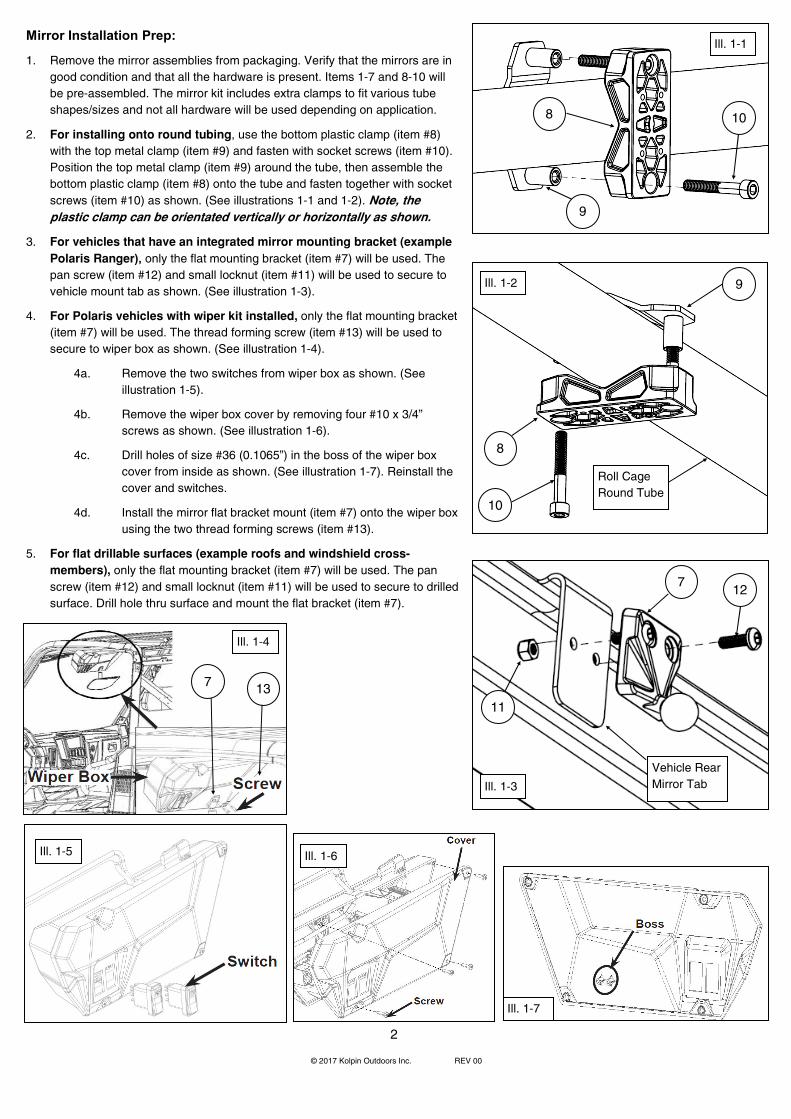
Mirror Installation Prep:
1. Remove the mirror assemblies from packaging. Verify that the mirrors are in
good condition and that all the hardware is present. Items 1-7 and 8-10 will
be pre-assembled. The mirror kit includes extra clamps to fit various tube
shapes/sizes and not all hardware will be used depending on application.
2. For installing onto round tubing, use the bottom plastic clamp (item #8)
with the top metal clamp (item #9) and fasten with socket screws (item #10).
Position the top metal clamp (item #9) around the tube, then assemble the
bottom plastic clamp (item #8) onto the tube and fasten together with socket
screws (item #10) as shown. (See illustrations 1-1 and 1-2). Note, the
plastic clamp can be orientated vertically or horizontally as shown.
3. For vehicles that have an integrated mirror mounting bracket (example
Polaris Ranger), only the flat mounting bracket (item #7) will be used. The
pan screw (item #12) and small locknut (item #11) will be used to secure to
vehicle mount tab as shown. (See illustration 1-3).
4. For Polaris vehicles with wiper kit installed, only the flat mounting bracket
(item #7) will be used. The thread forming screw (item #13) will be used to
secure to wiper box as shown. (See illustration 1-4).
4a. Remove the two switches from wiper box as shown. (See
illustration 1-5).
4b. Remove the wiper box cover by removing four #10 x 3/4”
screws as shown. (See illustration 1-6).
4c. Drill holes of size #36 (0.1065”) in the boss of the wiper box
cover from inside as shown. (See illustration 1-7). Reinstall the
cover and switches.
4d. Install the mirror flat bracket mount (item #7) onto the wiper box
using the two thread forming screws (item #13).
5. For flat drillable surfaces (example roofs and windshield cross-
members), only the flat mounting bracket (item #7) will be used. The pan
screw (item #12) and small locknut (item #11) will be used to secure to drilled
surface. Drill hole thru surface and mount the flat bracket (item #7). 12
13
Ill. 1-3
Ill. 1-4
Ill. 1-1
Ill. 1-2
7
7
8
9
8
9
10
10
Roll Cage
Round Tube
11
Vehicle Rear
Mirror Tab
Ill. 1-5 Ill. 1-6
Ill. 1-7

3
© 2017 Kolpin Outdoors Inc. REV 00
Mirror Mounting Instructions:
1. For your specific vehicle configuration listed on page 2, position - clamp and fasten the
assembled mirror onto the vehicle in desired location. If using the tube clamp, the flat
bracket (item #7) attaches to the bottom plastic clamp (item #8) using the two thread
forming screws (item #13) as shown. (See illustration 2-1). Note, the flat bracket can be
positioned onto the plastic clamp in multiple orientations. If using the flat bracket only,
please use the pan screws (item #12) and small locknuts (item #11) for fastening as
shown. (See illustration 2-2).
2. Tighten the screws to specified torque setting. WARNING: Do not over tighten hardware or
damage can occur.
Torque Charts: Tighten all screws to their specified torque values listed in below table.
3. Pivot mirror to desired viewing angle by
loosening (turn counter-clockwise) the thumb screw
(item #5) and then tighten (turn clockwise) to secure
into position as shown. (See illustration 2-3). Note, if
the thumb screw (item #5) is loosened too much,
the clamp arms (items #3 and #4) can allow mirror (item #1) to become disconnected
from the ball studs - please support mirror while making adjustments.
Use and Care Information:
• Check the accessory mounts frequently and retighten if necessary.
• Replace this accessory with a new one if it is damaged or discolored excessively.
• When this accessory becomes dirty, rinse it thoroughly with cool water to remove loose
dirt, then wipe with a clean cloth or sponge. Never use petroleum solvents such as
gasoline, thinner, benzene, acid or alkaline cleaners.
• Rearview mirror is not intended for on-road use.
For additional assistance, please contact Kolpin technical service department at (877) 956-5746 or (763) 478-5800 or email [email protected]
SPARE KITS Hardware &
clamp kit P/N:
98301 Item Description
2 Threaded Ball Stud 1x
5 Thumb Screw 1x
6 Hex Locknut, Zinc Plated, M6-1.0 1x
10 Socket Screw, Zinc Plated, M6-1.0 x 40mm LG 2x
11 Locknut, Zinc Plated, #8-32 2x
12 Pan Screw, Zinc Plated, #8-32 x 0.5in LG 2x
13 Thread Forming Screw for Plastic Clamp 2x
1
12
Item N*m kgf*m lbf*ft
2 13.6 1.4 10
12, 13 1.4 0.1 1
10 5 0.5 4
Ill. 2-3
Ill. 2-2
5
One Year Limited Warranty
For the period of one (1) year from the purchase date, Kolpin will replace for the original purchaser, free of charge, any part or parts found upon examination by Kolpin to be defective in material, workmanship, or both.
All transportation costs incurred submitting product to Kolpin for warranty consideration must be borne by the purchaser. If Kolpin determines that the product must be returned to the factory for credit, please call 1-877-956-5746 for a Return Merchandise Authorization
(RMA) number and shipping instructions.
This warranty does not apply to parts that have been damaged by accident, alteration, abuse, improper maintenance, normal wear, or
other causes beyond the manufacturer’s control. In order to protect you and your ATV, certain parts of the accessory system and/or
hardware are designed to fail when the equipment is over-stressed. Parts that are lost due to loosening and improper maintenance are not
covered under warranty. This warranty does not cover removal or reinstallation labor fees of the plow system and related components.
Peripheral products such as engines, electric motors, and actuators may carry an original manufacturer’s warranty. Most hardware is
general in nature and is easily obtained locally. Be sure to replace with minimum metric class 8.8 specification.
Ill. 2-1
13
11

1
© 2017 Kolpin Outdoors Inc. REV 00
Rétroviseur universel pour VUTT
Guide d’utilisation | N° de pièce : 98300
Contenu :
2
1
4
3
5
9
11
12
8
13
6
N° Qté Description
1 1 Rétroviseur central
2 1 Pivot à rotule fileté
3 1 Pince de bras arrière
4 1 Pince de bras avant
5 1 Vis à oreilles
6 1 Contre-écrou hexagonal zingué M6-1.0
7 1 Support de montage à plat
8 1 Pince en plastique inférieure de tube
9 1 Pince en métal supérieure de tube
10 2 Vis à tête creuse zinguée M6-1.0 x 40 mm
11 2 Contre-écrou zingué #8-32
12 2 Vis à tête cylindrique bombée zinguée
13 2 Vis autotaraudeuse pour pince en plastique
Avant de commencer, veuillez lire ces instructions et vous assurer de disposer de toutes les pièces et de tous les outils requis. Conservez ces instructions pour référence ultérieure et pour commander des pièces.
Remarque : S’il manque une pièce, ne rapportez pas l’article au magasin. Téléphonez-nous sans frais au 877 956-5746 pour obte-
nir de l’aide.
7 10
Kolpin Outdoors, Inc. | 9955 59th Ave N | Plymouth, MN 55442
877 956-5746 ou 763 478-5800 | www.kolpin.com | [email protected]
Ce rétroviseur est conçu pour un montage univer-sel simple et rapide à toute barre tubulaire, notam-ment sur une cage de retournement de VUTT ou une surface plane perçable. Cet ensemble convient à une tubulure de
1 1/2 po à 2 po de diamètre. La pince s’utilise à la verticale ou à l’horizontale. Les deux rotules faciles à régler multiplient les possibilités de positionne-ment. Remarque : L’installation pourrait être
facilitée par le retrait au préalable de certains
éléments du véhicule.
Outils requis :
• Clé hexagonale ou douille de 5 mm
• Tournevis à embout T20
• Clé ou douille de 11/32 po
• Clé à cliquet (pour les douilles)

2
© 2017 Kolpin Outdoors Inc. REV 00
Préparation à la pose du rétroviseur :
1. Sortez le rétroviseur de l’emballage. Assurez-vous que le rétroviseur est en bon état et qu’il ne manque aucune fixation. Les pièces 1 à 7 et 8 à 10 sont déjà assemblées. Cet ensemble contient des pinces supplémentaires conve-nant à des tubulures de formes/tailles variées, qui ne seront pas toutes utili-sées selon le véhicule.
2. Pour une installation sur une tubulure ronde, utilisez la pince en plas-
tique inférieure (8) et la pince en métal supérieure (9), que vous fixerez
avec les vis à tête creuse (10). Placez la pince en métal supérieure (9)
sur la tubulure, puis placez-y la pince en plastique inférieure (8) et fixez-
les avec les vis à tête creuse (10) comme le montre l’illustration (1-1 et 1
-2). Remarque : La pince en plastique peut être placée à la verticale ou à
l’horizontale comme le montre l’illustration.
3. Pour les véhicules pourvus d’un support de montage de rétroviseur
intégré (comme le modèle Polaris Ranger), seul le support de montage
à plat (7) sera utilisé. La vis à tête cylindrique bombée (12) et le contre-
écrou (11) serviront à fixer le rétroviseur à la languette de montage du
véhicule comme le montre l’illustration (1-3).
4. Pour les véhicules Polaris munis du nécessaire d’essuie-glace, seul le
support de montage à plat (7) sera utilisé. La vis autotaraudeuse (13)
servira à fixer le rétroviseur au boîtier d’essuie-glace comme le montre
l’illustration (1-4).
4a. Enlevez les deux commutateurs du boîtier d’essuie-glace comme le montre l’illustration (1-5).
4b. Enlevez le couvercle du boîtier d’essuie-glace en déposant les quatre vis #10 x 3/4 po comme le montre l’illustration (1-6).
4c. À partir de l’intérieur, percez des trous #36 (0,1065 po) dans le bossage du couvercle du boîtier d’essuie-glace comme le montre l’illus-tration (1-7). Remettez le couvercle et les commutateurs.
4d. Installez le support de montage à plat (7) sur le boîtier d’essuie-
glace en utilisant les deux vis autotaraudeuses (13).
5. Pour les surfaces planes
perçables (comme les toits
ou les traverses de pare-
brise), seul le support de
montage à plat (7) sera utili-
sé. La vis à tête cylindrique
bombée (12) et le contre-
écrou (11) serviront à fixer le
rétroviseur à la surface per-
cée. Percez un trou dans la
surface et montez-y le sup-
port de montage à plat (7).
12
13
Ill. 1-3
Ill. 1-4
Ill. 1-1
Ill. 1-2
7
7
8
9
8
9
10
10
Tubulure ronde de la cage de retournement
11
Languette de montage du rétroviseur
Ill. 1-5 Ill. 1-6
Ill. 1-7
Boîtier d'essuie-glace
Vis
Commutateur
Vis
Couvercle
Bossage

3
© 2017 Kolpin Outdoors Inc. REV 00
Instructions de montage du rétroviseur :
1. Selon la configuration du véhicule figurant à la page 2, placez, pincez et fixez le rétroviseur assemblé à l’endroit voulu. Si vous utilisez la pince de tube, le support de montage à plat (7) se fixe à la pince en plastique inférieure (8) avec les deux vis autotaraudeuses (13) comme le montre l’illustration (2-1). Remarque : Le support de montage à plat peut être
placé à divers endroits sur la pince en plastique. Si vous utilisez uniquement le support de montage à plat, servez-vous des vis à tête cylindrique bombée (12) et des contre-
écrous (11) pour fixer le rétroviseur comme le montre l’illustration (2-2).
2. Serrez les vis au couple prescrit. AVERTISSEMENT : Évitez de trop serrer les fixations, au risque de causer des dommages.
Couples de serrage : Serrez toutes les vis au couple figurant dans le tableau ci-dessous.
3. Faites pivoter le rétroviseur jusqu’à l’angle voulu en desserrant (sens antihoraire) la vis à oreilles (5), puis en la serrant (sens horaire) pour le fixer en posi-tion comme le montre l’illustration (2-3). Remarque :
Si la vis à oreilles (5) est trop desserrée, les
pinces de bras (3 et 4) risquent de se défaire des rotules retenant le rétroviseur (1).
Veuillez soutenir le rétroviseur pendant que vous faites les réglages.
Utilisation et entretien :
• Vérifiez fréquemment les supports du rétroviseur et resserrez-les au besoin.
• Remplacez cet accessoire s’il est endommagé ou décoloré à l’excès.
• Lorsque cet accessoire est sale, rincez-le à fond à l’eau fraîche pour enlever la saleté, puis essuyez-le avec un chiffon ou une éponge propre. N’utilisez jamais de solvant pétrolier comme de l’essence, du diluant, du benzène, de l’acide ou des nettoyants alcalins.
• Le rétroviseur n’est pas conçu pour un usage routier.
Pour obtenir de l’assistance, veuillez communiquer avec le service d’aide technique Kolpin au 877 956-
5746 ou 763 478-5800, ou à [email protected].
ENSEMBLES DE RECHANGE Ens. de fixa-
tions et pinces
Pièce n° : 98301 N° Description
2 Pivot à rotule fileté 1x
5 Vis à oreilles 1x
6 Contre-écrou hexagonal zingué M6-1.0 1x
10
Vis à tête creuse zinguée M6-1.0 x 40 mm (long.) 2x
11 Contre-écrou zingué #8-32 2x
12
Vis à tête cylindrique bombée zinguée, #8-32 x 0,5 po (long.) 2x
13 Vis autotaraudeuse pour pince en plastique 2x
1
12
N° N m kgf m lbf pi
2 13,6 1,4 10
12, 13 1,4 0,1 1
10 5 0,5 4
Ill. 2-3
Ill. 2-2
5
Garantie limitée d’un an
Durant une période d’un an à compter de la date d’achat, Kolpin remplacera à l’acheteur initial, sans frais, toute pièce qui, après examen par Kolpin, est jugée défectueuse du point de vue des matériaux, de la main-d’œuvre ou des deux.
Les coûts de transport visant à soumettre l’article à Kolpin pour un examen au titre de la garantie doivent être assumés en totalité par l’acheteur. Advenant que Kolpin détermine que l’article doit être retourné à l’usine pour obtenir un crédit, veuillez téléphoner au 877 956-5746 pour obtenir un numéro d’autorisa-tion de retour de marchandise (ARM) et les directives d’expédition.
Cette garantie ne s’applique pas aux pièces ayant été endommagées par un accident, une modification, un abus, un entretien inadéquat, une usure nor-
male ou toute autre cause échappant au contrôle du fabricant. Afin de vous protéger ainsi que votre VTT, certaines pièces ou fixations de l’accessoire ont
été conçues pour se rompre en cas de tension excessive. Toute pièce perdue en raison d’un mauvais serrage ou d’un entretien inadéquat n’est pas cou-
verte par cette garantie. La présente garantie ne couvre pas la main-d’œuvre pour enlever et remettre le chasse-neige et les composants connexes.
Certaines pièces accessoires, comme les moteurs ou les actionneurs, pourraient offrir une garantie du fabricant d’origine. La plupart des fixations sont de
nature générale et peuvent être obtenues localement. Assurez-vous de les remplacer par des modèles répondant minimalement aux normes de la classe
métrique 8.8.
Ill. 2-1
13
11