Embed Size (px)
Citation preview

�
UNIVERSAL STEELOSCOPESLU
REgISTRATION CERTIfICATE2.85�.047 PS
NPZ Optics State CorporationNovosibirsk Instrument-Making Plant

2
Attention!It is categorically forbidden to switch over the tumblers “ARC”,
“SPARK”, “CAPACITANCE” when the button contactor is closed in the steeloscope handle or when the tumbler “START” of the light source is switched on (if operations are hold stationary).
Avoid using steeloscope at open air in the rain and on the wet ground as well as when it is wet itself or its power unit.
Transport the device and the power unit from cold to warm premises in the tight closed cases to avoid sweating. The cases are to be open when devices get the ambient temperature (the change from -40 to +�8°C requires 2-3 hours).
The operations with the device can be executed both outside under the shed and indoors under the temperature from -40° to +45°C and relative humidity up to 80%.
the steeloscope requires careful handling. Prevent the head with insulator, spectrum handwheel and the eyepiece against impacts and excessive force.
Due to continuous product improvement, specifications are subject to change without notice.
!

3
1 APPLiCAtion oF tHe ARtiCLe
�.� The universal steeloscope SLU 2.85�.047 is designed for a quick visual qualitative and comparative quantitative spectral analysis of ferrous and non-ferrous alloys in the visible spectral region.
�.2 The universal steeloscope is used for proximate analyses on which accuracy there is no high demands. The samples of any size and form can be subjected to analysis directly at the site as well as in laboratory conditions.
�.3 The steeloscope can be used in the storehouses during checking material, at the stock-yard, stations of scrap material sorting, in the proximate analysis laboratories of the foundries, scientific-research laboratories.
2 SPeCiFiCAtionS
2.� The main parameters and dimensions of the universal steeloscope are given in the table �.
Table �
Main parameters and dimensions Standards
Operating spectral range, nm from 390 to 700Inverse linear dispersion, nm/mm for the region of 390 nm 0.8 for the region of 470 nm 2.0 for the region of 700 nm 6.8Resolving power, nm 0.089focal length of objective, mm 322.2Entrance slit width, mm 0.0�
Arc current, A 7
Spark current, A 3.5
Consumed power, VA 930
Input voltage, V AC 220
frequency, HZ 50±�Overall dimensions, mm, not more: of the steeloscope �75x�90x695 of the power unit 375x�50x350 of the light source 300x�80x380Total weight, kg, not more 35
+3,0 -�,0+3,0 -0,5+570 -270+22 -33

4
3 ComPoSition oF tHe ARtiCLe AnD inventoRy LiSt
3.� The composition of universal steeloscope and inventory list are given in the table 2.
Table 2 Designation Name Qty Note
2.85�.048 Steeloscope � 5.087.098 Power unit � 5.307.0�7 Light source � 5.5�9.002 Disc electrode � 6.�50.374 Support � 6.202.005 Rail � 6.894.026 Cramp � 6.434.2�� Mount � 6.644.3�2 Cable � 8.352.349 Rod � Spares 8.9�0.773 Screw 2 Screw M5-6gx�0.58.049 2 Shim 6.32.046 4 gOST �0450-78 Shim 6.65g.033 4 fuse link VPB6-26 5 7.723.06� Disk �0 7.723.06�-0� Disk �0 Lamp MN26-0.�2 5 8.640.��4 Protective glass 3 7.732.32� Electrode 2 Removable parts 6.434.�2� Mount � tools 6.890.030-�2 Screwdriver � Accessories 6.899.007 gauge � -0� gauge � -02 gauge � -03 gauge � Socket RSh-tsch-20-0-0�-�0/220 � Consumer’s container 4.�6�.526 Case � 4.�6�.547 Case � transporting Container 4.�7�.424 Case �
Service documentation 2.85�.047 ПС Registration certificate � 2.85�.047 ПС� Methods of spectral analysis � of steels with help of universal steeloscope SLU
Made as a separate document
5
4 ConStRACtion AnD PRinCiPLe oF oPeRAtion 4.1 Principle of operation of universal steeloscope
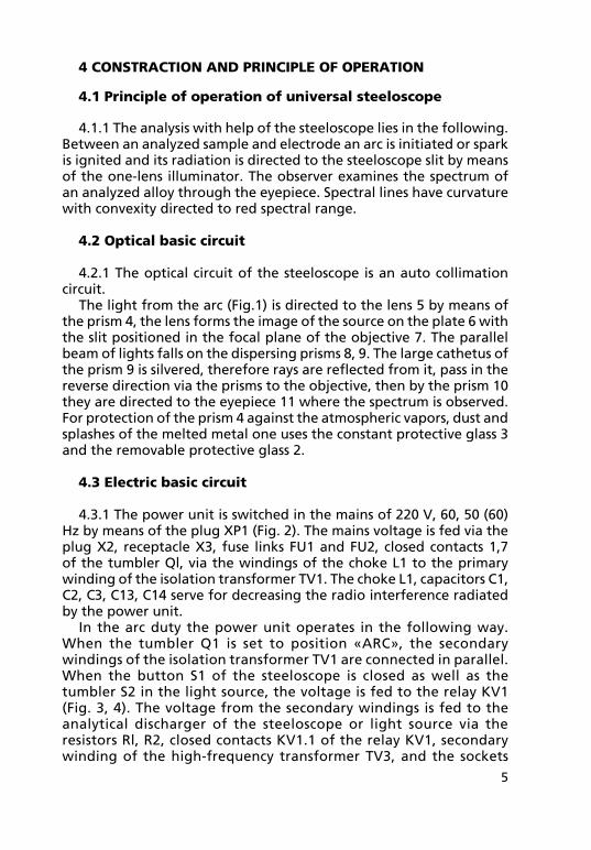
4.�.� The analysis with help of the steeloscope lies in the following. Between an analyzed sample and electrode an arc is initiated or spark is ignited and its radiation is directed to the steeloscope slit by means of the one-lens illuminator. The observer examines the spectrum of an analyzed alloy through the eyepiece. Spectral lines have curvature with convexity directed to red spectral range.
4.2 optical basic circuit 4.2.� The optical circuit of the steeloscope is an auto collimation
circuit.The light from the arc (fig.�) is directed to the lens 5 by means of
the prism 4, the lens forms the image of the source on the plate 6 with the slit positioned in the focal plane of the objective 7. The parallel beam of lights falls on the dispersing prisms 8, 9. The large cathetus of the prism 9 is silvered, therefore rays are reflected from it, pass in the reverse direction via the prisms to the objective, then by the prism �0 they are directed to the eyepiece �� where the spectrum is observed. for protection of the prism 4 against the atmospheric vapors, dust and splashes of the melted metal one uses the constant protective glass 3 and the removable protective glass 2.
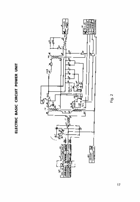
4.3 electric basic circuit
4.3.� The power unit is switched in the mains of 220 V, 60, 50 (60) Hz by means of the plug XP� (fig. 2). The mains voltage is fed via the plug X2, receptacle X3, fuse links fU� and fU2, closed contacts �,7 of the tumbler Ql, via the windings of the choke L� to the primary winding of the isolation transformer TV�. The choke L�, capacitors C�, C2, СЗ, С�3, C�4 serve for decreasing the radio interference radiated by the power unit.
In the arc duty the power unit operates in the following way. When the tumbler Q� is set to position «ARC», the secondary windings of the isolation transformer TV� are connected in parallel. When the button S� of the steeloscope is closed as well as the tumbler S2 in the light source, the voltage is fed to the relay KV� (fig. 3, 4). The voltage from the secondary windings is fed to the analytical discharger of the steeloscope or light source via the resistors Rl, R2, closed contacts KV�.� of the relay KV�, secondary winding of the high-frequency transformer TV3, and the sockets

6
X4, X5. Simultaneously from one of the sections of the secondary winding of the isolation transformer TV�, via the resistor Rl, closed contacts KV�.� KV�.2 of the relay KV�, resistor R4 the voltage is fed to the primary winding of the high-voltage transformer TV2. The high voltage is removed from the secondary winding and fed to the spark oscillatory circuit, composed of the capacitors ��, �2 and inductance coil of the primary winding of the high-frequency transformer TV3 and spark discharger. The capacitors of the oscillatory circuit are charged from the secondary winding of the high-voltage transformer TV2. When the voltage across the capacitors is equal to the break-down voltage of the discharger by value, the break-down of the air gap takes place and the capacitors are discharged into the circuit of the primary winding of the high-frequency transformer TV3. The process is repeated each half-period of the supplying voltage. The oscillations of high frequency arisen in the oscillatory circuit are transformed by the high-frequency transformer TV3, superimposed on the low voltage in the second winding of the transformer TV3 and fed to the discharger of the steeloscope or light source via the sockets X4, X5.
In the spark duty the supply unit operates in the following way. When the tumbler Q� is set to position «SPARK», the sections of the secondary winding of the isolation transformer are switched on in series. Simultaneously the extra capacitors C4…C9 are connected to the capacitor C�O. The value of the extra capacitance is selected by the switch Q2 «CAPACITANCE». Such circuit gives the pulse discharge with the increased current density. The high-frequency part of the circuit in the spark duty operates similarly to the arc duty.
for improving the heat exchange of the supply unit the ventilator Ml is provided which blows the resistors Rl, R2. The lamp H� serves as an indicator of switching the power unit in the mains. After de-energization of the relay KV� the resistor R3 discharges the residual voltage across the capacitors C4...C�0.
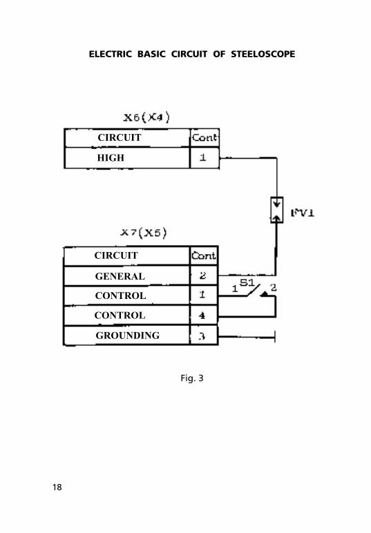
4.3.2 The electric basic circuit of the steeloscope consists of the discharger fV� (fig. 3) to which the voltage is fed via the plugs X6, X7. The button S� is designed for switching the relay KV� in the circuit of the supply unit.
4.3.3 The electric basic circuit of the light source is composed of the discharger fV2 (fig.4) to which the voltage is fed via the plugs X8, X9. The tumbler S2 and the holding key S3 are designed for switching the relay KV� in the circuit of the power unit.
When the power unit operates together with the light source, the former is grounded via the terminal XT� (fig. 2), and the latter — via the terminal XT2 (fig. 4).

7
4.4 Design of universal steeloscope
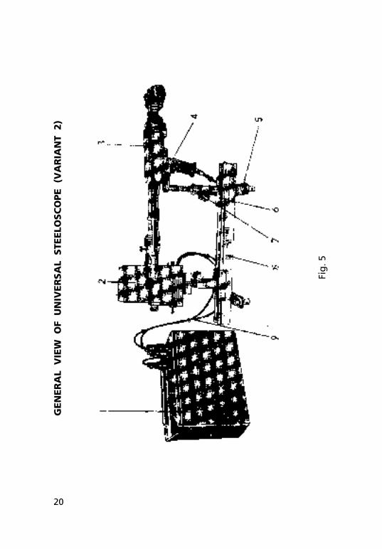
4.4.� The universal steeloscope includes the steeloscope itself 3 (fig. 5), the light source 2, the power unit �, the rail 8, the support 6, the cable 9.
4.4.2 The steeloscope consists of the head with the illuminating system and spectral apparatus.
The casing of the head �6 (fig. 6a) embodies the constant protective glass, prism and lens. In front of the constant protective glass the removable protective glass is positioned. The removable protective glass takes the splashes of the melted metal in operation and protects the constant protective glass against damage. When the removable protective glass becomes spotty (due to burning of the glass) which brings about the noticeable weakening of the spectrum intensity it should be renewed.
fixed on the head �6 with the help of the screw �7 is the mount � which carries three tungsten contacts �8. The latter serves for bringing one of the poles of the mains to the object to be analyzed as well as for stability of the steeloscope in operation. There is a hinged gauge 2 on the head which allows setting the rod electrode 3 to the required position.
for analysis of the small parts, the removable mount �9 (fig. 6b) is completed with the steeloscope, it is fixed to the head by means of screw �7. In operation in the open air a casing 29 is put on the mount �9.
The head is isolated from the rest part of the steeloscope by the insulator 6 (fig. 6a). There is the split bushing 5 in the insulator hole; the rod electrode 3 or the holder of the disc electrode 25 (fig. 6b) is inserted in the split bushing, their fixation is performed by means of the screw 4 (fig. 6a). The disc electrode can be used for a long time without sharpening; for this purpose the rotation of the disc 27 (fig. 6b) is provided by using the handle 28 with fixation at each �5°. The steeloscope comes with the rod (steel) and disc (steel and copper) electrodes. The steel electrodes are made of steel of U7 grade, the copper ones are made of copper of M�T2 grade. for manufacture of the steel electrodes it is allowed to use the steels of U8, U9, U�0, U�2, U7А, U8А, U9А grades.
The required turn of prism in operation is carried out with the help of the rod �3 (fig. 6a) which is fastened to the steeloscope by means of the clip �4 and lock screw �5 in the hinge.
The supply voltage from the power unit is fed to the head and electrode via the wires 20, 2� (fig. 6b).
The spectral apparatus is enclosed in the casing �2 on which the eyepiece 8 is fixed and the insulator with the head is connected with the help of the pipe 25. The mount with the optical slit are
8
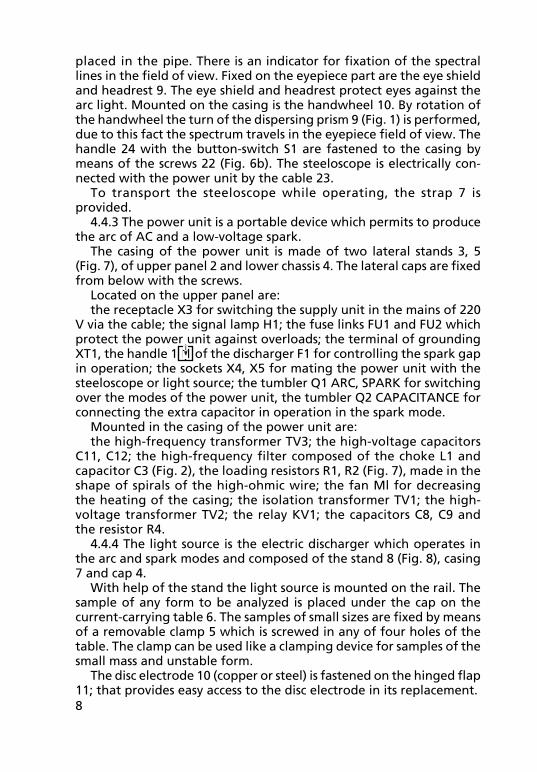
placed in the pipe. There is an indicator for fixation of the spectral lines in the field of view. fixed on the eyepiece part are the eye shield and headrest 9. The eye shield and headrest protect eyes against the arc light. Mounted on the casing is the handwheel �0. By rotation of the handwheel the turn of the dispersing prism 9 (fig. �) is performed, due to this fact the spectrum travels in the eyepiece field of view. The handle 24 with the button-switch S� are fastened to the casing by means of the screws 22 (fig. 6b). The steeloscope is electrically con-nected with the power unit by the cable 23.
To transport the steeloscope while operating, the strap 7 is provided.
4.4.3 The power unit is a portable device which permits to produce the arc of AC and a low-voltage spark.
The casing of the power unit is made of two lateral stands 3, 5 (fig. 7), of upper panel 2 and lower chassis 4. The lateral caps are fixed from below with the screws.
Located on the upper panel are:the receptacle X3 for switching the supply unit in the mains of 220
V via the cable; the signal lamp H�; the fuse links fU� and fU2 which protect the power unit against overloads; the terminal of grounding XT�, the handle � of the discharger f� for controlling the spark gap in operation; the sockets X4, X5 for mating the power unit with the steeloscope or light source; the tumbler Q� ARC, SPARK for switching over the modes of the power unit, the tumbler Q2 CAPACITANCE for connecting the extra capacitor in operation in the spark mode.
Mounted in the casing of the power unit are:the high-frequency transformer TV3; the high-voltage capacitors
��, �2; the high-frequency filter composed of the choke L� and capacitor C3 (fig. 2), the loading resistors R�, R2 (fig. 7), made in the shape of spirals of the high-ohmic wire; the fan Ml for decreasing the heating of the casing; the isolation transformer TV�; the high-voltage transformer TV2; the relay KV�; the capacitors C8, C9 and the resistor R4.
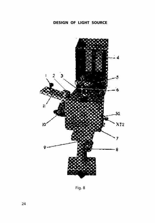
4.4.4 The light source is the electric discharger which operates in the arc and spark modes and composed of the stand 8 (fig. 8), casing 7 and cap 4.
With help of the stand the light source is mounted on the rail. The sample of any form to be analyzed is placed under the cap on the current-carrying table 6. The samples of small sizes are fixed by means of a removable clamp 5 which is screwed in any of four holes of the table. The clamp can be used like a clamping device for samples of the small mass and unstable form.
The disc electrode �0 (copper or steel) is fastened on the hinged flap ��; that provides easy access to the disc electrode in its replacement.

9
The disc electrode can be used for a long time without sharpening, for this purpose the rotation of the disc by means of the handle 2 with fixation at each �5° is provided.
The required gap between the sample to be analyzed and electrode is set with the use of the superimposing gauges 3 by lifting the disc electrode with the help of the screw �. for elimination of the cut-off of the light flux it is a recommended practice to set the sample to be analyzed on the table by its edge above the disc electrode.
The voltage from the power unit to the light source is laid by the braid with connectors. In operation the power unit is switched on by means of the tumbler S2 with the light source. The holding key breaks a low-voltage circuit if the cap is being opened and protects an operator against current rush. The obligatory grounding of the light source is performed with the help of the terminal XT2.
for collection and removal of scale from the casing of the light source the tray is provided.
4.4.5 The rail 8 (fig. 5) of a standard profile is designed for fixation of the support and light source. for mounting on the table the rail is provided with four adjustable supports 5.
The support 6 (fig. 5) is designed for fixation of the steeloscope on the rail. The height of the support is controlled by means of the nut 7. The steeloscope is mounted in the guide 4 and clamped by means of the handle.
5 SAFety meASUReS
5.� The universal steeloscope is a first grade anti-electrical shock device, i.e. it has ground cable and a fork with grounding contacts.
5.2 The elements which are intended to protect from occasional touch to current-carrying parts are housings of the steeloscope and the power unit.
5.3 Before switching the steeloscope in the mains the power unit and light source should be grounded. The premises should be equipped with a combined extract and input ventilation and grounding mat of maximum resistance of 4 Ohms.
5.4 During the operation avoid touching the steeloscope head and electrode. The electrodes should be replaced only when the power unit is switched off.
5.5 Use rubber galoshes and gloves while operating.5.6 It is forbidden to look at the arc (spark) with the unprotected
eyes.5.7 The operation is finished or in intervals between analyses the
supply unit should be switched off.

�0
5.8 Safety measures should be in correspondence with the measures that are hold while plants up to �,000 V are used.
6 PRePARAtion oF ARtiCLe FoR oPeRAtion
6.1 mounting of universal steeloscope
6.�.� Depending on the dimensions of the sample to be analyzed and on the type of the operations to be performed the universal steeloscope can be mounted in two variants:
variant � — the steeloscope 3 (fig. 9) with the removable mounts, power unit �, cable 2;
variant 2 — the steeloscope 3 (fig. 5), power unit �, light source 2, rail 8, support 6, cable 9.
When sorting the parts, analyzing the large-sized constructions, large forged pieces, scrap metal it is advisable to use variant �. When developing and introducing clarity in the methods of spectral analysis, or analyzing the lot of products of the small-sized sample, it is advisable to use variant 2.
6.2. mounting of universal steeloscope according to variant 1
6.2.� Mount and fix the rod on the steeloscope.6.2.2 Depending on the dimensions of the sample to be analyzed
mount the frame � (fig.6a) or �9 (fig.6b) on the steeloscope head.6.2.3 Mount the electrode required for operation (a steel or copper
one).6.2.4 Connect the steeloscope to the supply unit. Switch the power
unit in the mains with the help of the cable.
Attention! IT IS STRICTLY PROHIBITED TO SWITCH THE STEELOSCOPE INTO THE DWELLINg HOUSE MAINS.
6.3 mounting of universal steeloscope according to variant 2
6.3.� Mount and fix the rod on the steeloscope.6.3.2 Remove the mount from the steeloscope head.6.3.3 Mount the rail on the table.6.3.4 Mount the light source and support on the rail. fix the
steeloscope on the support. Direct the steeloscope tube along the rail.
6.3.5 Mount any sample on the table of the light source.6.3.6 Connect the light source to the power unit. Switch the
��
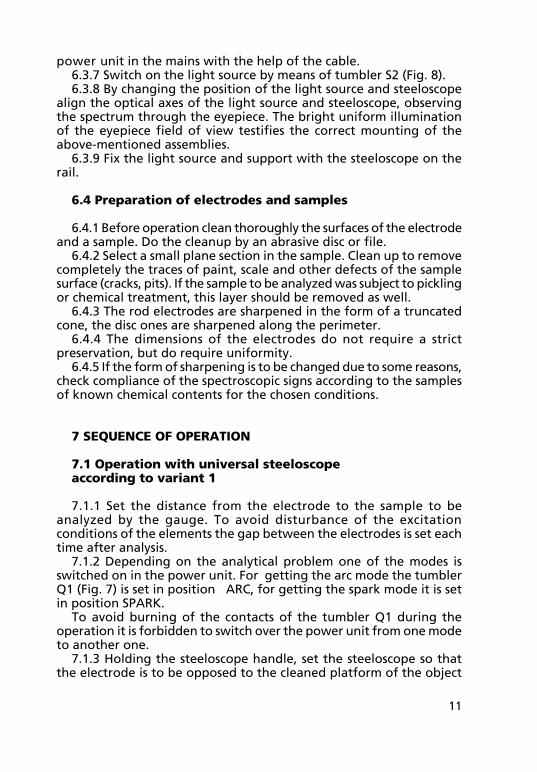
power unit in the mains with the help of the cable.6.3.7 Switch on the light source by means of tumbler S2 (fig. 8).6.3.8 By changing the position of the light source and steeloscope
align the optical axes of the light source and steeloscope, observing the spectrum through the eyepiece. The bright uniform illumination of the eyepiece field of view testifies the correct mounting of the above-mentioned assemblies.
6.3.9 fix the light source and support with the steeloscope on the rail.
6.4 Preparation of electrodes and samples
6.4.� Before operation clean thoroughly the surfaces of the electrode and a sample. Do the cleanup by an abrasive disc or file.
6.4.2 Select a small plane section in the sample. Clean up to remove completely the traces of paint, scale and other defects of the sample surface (cracks, pits). If the sample to be analyzed was subject to pickling or chemical treatment, this layer should be removed as well.
6.4.3 The rod electrodes are sharpened in the form of a truncated cone, the disc ones are sharpened along the perimeter.
6.4.4 The dimensions of the electrodes do not require a strict preservation, but do require uniformity.
6.4.5 If the form of sharpening is to be changed due to some reasons, check compliance of the spectroscopic signs according to the samples of known chemical contents for the chosen conditions.
7 SeQUenCe oF oPeRAtion
7.1 operation with universal steeloscope according to variant 1
7.�.� Set the distance from the electrode to the sample to be analyzed by the gauge. To avoid disturbance of the excitation conditions of the elements the gap between the electrodes is set each time after analysis.
7.�.2 Depending on the analytical problem one of the modes is switched on in the power unit. for getting the arc mode the tumbler Q� (fig. 7) is set in position ARC, for getting the spark mode it is set in position SPARK.
To avoid burning of the contacts of the tumbler Q� during the operation it is forbidden to switch over the power unit from one mode to another one.
7.�.3 Holding the steeloscope handle, set the steeloscope so that the electrode is to be opposed to the cleaned platform of the object
�2
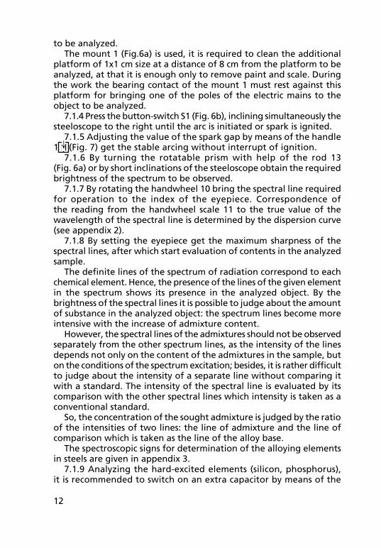
to be analyzed.The mount � (fig.6a) is used, it is required to clean the additional
platform of �x� cm size at a distance of 8 cm from the platform to be analyzed, at that it is enough only to remove paint and scale. During the work the bearing contact of the mount � must rest against this platform for bringing one of the poles of the electric mains to the object to be analyzed.
7.�.4 Press the button-switch S� (fig. 6b), inclining simultaneously the steeloscope to the right until the arc is initiated or spark is ignited.
7.�.5 Adjusting the value of the spark gap by means of the handle � (fig. 7) get the stable arcing without interrupt of ignition.
7.�.6 By turning the rotatable prism with help of the rod �3 (fig. 6a) or by short inclinations of the steeloscope obtain the required brightness of the spectrum to be observed.
7.�.7 By rotating the handwheel �0 bring the spectral line required for operation to the index of the eyepiece. Correspondence of the reading from the handwheel scale �� to the true value of the wavelength of the spectral line is determined by the dispersion curve (see appendix 2).
7.�.8 By setting the eyepiece get the maximum sharpness of the spectral lines, after which start evaluation of contents in the analyzed sample.
The definite lines of the spectrum of radiation correspond to each chemical element. Hence, the presence of the lines of the given element in the spectrum shows its presence in the analyzed object. By the brightness of the spectral lines it is possible to judge about the amount of substance in the analyzed object: the spectrum lines become more intensive with the increase of admixture content.
However, the spectral lines of the admixtures should not be observed separately from the other spectrum lines, as the intensity of the lines depends not only on the content of the admixtures in the sample, but on the conditions of the spectrum excitation; besides, it is rather difficult to judge about the intensity of a separate line without comparing it with a standard. The intensity of the spectral line is evaluated by its comparison with the other spectral lines which intensity is taken as a conventional standard.
So, the concentration of the sought admixture is judged by the ratio of the intensities of two lines: the line of admixture and the line of comparison which is taken as the line of the alloy base.
The spectroscopic signs for determination of the alloying elements in steels are given in appendix 3.
7.�.9 Analyzing the hard-excited elements (silicon, phosphorus), it is recommended to switch on an extra capacitor by means of the

�3
tumbler Q2 CAPACITANCE (fig. 7) on the power unit. 7.�.�0 The power unit operating mode should be cycled, alternating
5 minutes on and 5 minutes off intervals.
7.2 operation with Universal Steeloscope by variant 2
7.2.� Set the distance from the electrode to the analyzed sample by gauges.
7.2.2 Put the sample to be analyzed on the table of the light source. Close the cap of the light source.
7.2.3 Set the required mode for operation on the power unit and switch on the light source by means of the tumbler S2 (fig. 8).
7.2.4 Repeat the operation in compliance with pp. 7.�.5-7.�.�0.
8 mAintenAnCe
8.1 General instructions
8.�.� The maintenance is the system of the preventive maintenance measures which allows keeping the universal steeloscope in the operating condition.
8.�.2 The maintenance should be performed with the power unit switched off.
8.�.3 The maintenance should be carried out only by the specialists who have passed a course of special training.
8.2 Kinds and intervals of maintenance
8.2.� Cleaning of the contacts of the relay KV� (fig. 7) of RPU-2 type perform with the use of alcohol once in three months.
8.2.2 Cleaning of the contacts of the discharger perform by a fine emery paper with the frequence of not more than after each 500 h of operation.
8.2.3 Cleaning of the protective glass and eyepiece lens is performed with the use of alcohol in case of contamination and deterioration of the spectrum visibility.
8.2.4 The replacement of the protective glass execute in case of burning-out of the glass (indelible spots).
for replacement of the removable protective glass loosen screws � (fig. �0), take out the glass 2 and set a new glass from the maintenance kit.

�4
9 tRAnSPoRtAtion AnD StoRAGe
The instrument can be transported by any kind of the covered transport at the temperatures not higher than 40°C and not lower than minus 50°C. In transportation and storage it is necessary to protect the case with the device against penetration of moisture, direct sun rays heating, against impacts and shaking. It is not permitted to turn over the cases, to put them on snow or wet surface, or throw them.
The device, packed in the case must be stored in the dry heated store-houses with the ambient temperature from 8°C to 35 °C and relative humidity of maximum 80%. The diurnal fluctuations of the temperature should not cause the condensation of the air moisture on the metal parts of packing. In the premises of the store-houses the vapors of acids, alkalis and other substances which cause the instrument damage must be avoided.
10 ACCePtAnCe CeRtiFiCAte
The universal steeloscope SLU, serial # ,is found serviceable and is packed according to the stated requirements.
Date of manufacture and preservation .
Signatures

�5
f I g U R E S

�6
fig. �
oPtiCAL BASiC CiRCUit
�7
eLe
CtR
iC B
ASiC
C
iRC
Uit
Po
WeR
U
nit
fig
. 2
Gro
undi
ng
Gro
undi
ng
Gro
und
Gro
und
Gro
undi
ng
�8
eLeCtRiC BASiC CiRCUit oF SteeLoSCoPe
fig. 3
GROUNDING
CONTROL
CONTROL
GENERAL
CIRCUIT
CIRCUIT
HIGH

�9
eLeCtRiC BASiC CiRCUit oF LiGHt SoURCe
fig. 4
Circuit Circuit
CircuitHigh
GeneralControlControlGrounding
Grounding
20
Gen
eR
AL
vie
W o
F U
niv
eR
SA
L S
teeLo
SC
oPe (v
AR
iAn
t 2
)
fig
. 5

2�
DeSiG
n o
F S
teeLo
SC
oPe
fig
. 6a

22
fig
. 6b

23
DeSiG
n o
F P
oW
eR
U
nit
fig
. 7
24
DeSiGn oF LiGHt SoURCe
fig. 8

25
GeneRAL vieW oF UniveRSAL SteeLoSCoPe(vARiAnt 1)
fig. 9

26
iLLUminAtinG HeAD
fig. �0

27
Appendix �
Designation Name Qty Note
Capacitors
С�, С2 KTP-3Aa-N70-400V-0.�5 µf 2
С�5, С�6
С3 MBgCh-�-2A-250-�µf±�0%-V �
С4...С9 MBgCh-�-�-250-�0µf±�0%-V 6
С�0 MBgCh-�-2A-250-�µf±�0%-V �
С��, С�2 KVI-3-5-4700±�0% 2
С�3, С�4 K73-�7-630V-0.0�µf±�0% 2
f� �
fV� �
fV2 �
fU�, fU2 fuse link VPB6-26V 2
Н� Lamp MN26-0.�2 �
KV� Relay RPU-2-06002 UZA ��0 V 50 Hz �
L� Choke 5.775.0�3 �
М� Ventilator VN2-V �
Q�, Q2 Three-pole tumbler PTZ-�0T 2
S� Button K3 �
S2 Tumbler PT24 �
S3 Switcher PKN6-�V �
R�, R2 Resistor 5.�73.04� 2
R3 Resistor C2-23-2-�0 kOhm±�0% �
R4 Resistor C5-35V-3-�0 kOhm±�0% �
R5 Resistor C5-35V-3-20 kOhm±�0% �
TV� Transformer 5.702.006 �
TV2 Transformer 5.702.007 �
TV3 Transformer 5.775.0�4 �
Х� Plug VSh-tz-20-0�-�0/220 �
Х2 Link ShR20P3NSh7 �
Х3 Block ShR20P3ESh7 �
Х4 Socket 6.604.068 �
Х5 Socket 2RMT22BPN4g3V�V �
Х6, Х8 Plug 6.605.040 2
Х7, Х9 Plug 2RMT22KPN4Sh3V�V 2
ХТ�, ХТ2 Small-sized clamp 3M3 2
Discharger
Discharger
Discharger

28
DIS
PER
SIO
N C
UR
VE F
OR
STE
ELO
SCO
PE S
LU #
1st
Revo
luti
on
2n
d R
evo
luti
on
Han
dw
heel
scale
d
ivis
ion
Wave
- le
ng
ht

29
tABLe oF ContentS
1 Application of the article 32 Specifications 33 Composition of the article and inventory list 44 Constraction and principle of operation 5 4.� Principle of operation of universal steeloscope 5 4.2 Optical basic circuit 5 4.3 Electric basic circuit 5 4.4 Design of universal steeloscope 75 Safety measures 96 Preparation of article for operation �0 6.� Mounting of universal steeloscope �0 6.2 Mounting of universal steeloscope according to variant � �0 6.3 Mounting of universal steeloscope according to variant 2 �0 6.4 Preparation of electrodes and samples ��7 Sequence of operation �� 7.� Operation with universal steeloscope according to variant � �� 7.2 Operation with Universal Steeloscope by Variant 2 �38 maintenance �3 8.� general instructions �3 8.2 Kinds and intervals of maintenance �39 transportation and storage �410 Acceptance certificate �4 figures �5 Appendix 1 List of elements for electric circuits 27 Appendix 2 Dispersion curve for steeloscope SLU # 28
04.06