Embed Size (px)
Citation preview

Universal operation of small and medium size renewable energy systems
Prof. Marco Liserre, PhD, IEEE fellow
Head of the Chair of Power Electronics
Christian-Albrechts-Universität zu Kiel
Kaiserstr. 2 D-24143 Kiel Germany

Introduction
Decentralized control of the grid converter: from
“multifunctional” to “universal” converter
Voltage and current control alternatives
Harmonic rejection
Transition among different operation modes
Universal Operation of Wind Turbine Systems without
Storage
Outline
Marco Liserre [email protected]

Source: IET, Aalborg University
Power Flow
Information Flow
Generators
TransmissionNetwork
DistributionNetwork
Customers
Power Flow
Information Flow
Generators
TransmissionNetwork
DistributionNetwork
Customers
Generators
TransmissionNetwork
DistributionNetwork
Customers
Marco Liserre [email protected]
Only central power plants
Scenario: smart grid and renewables
Until 2000

Power Systems in 2012
Source: IET, Aalborg University
Power Flow
Information Flow
Generators
TransmissionNetwork
DistributionNetwork
Customers
Distributed Generation
Green Power
Power Flow
Information Flow
Generators
TransmissionNetwork
DistributionNetwork
Customers
Generators
TransmissionNetwork
DistributionNetwork
Customers
Distributed GenerationDistributed Generation
Green Power
Marco Liserre [email protected]
Scenario: smart grid and renewables
Distributed generation based on renewable energies is changing the face of power system
Ancillary services are the first tangible effect !

Power converters for photovoltaic systems • High efficiency (new topologies and new devices) • Transformer-less topologies and Central inverters • Extended lifetime • Reactive power injection (ancillary services)
Inverter market share Vincotech patent
Marco Liserre [email protected]

• Reliability • 10-20 MW wind turbines (power converter topologies and generators) • Paralleling of power converters or MV solutions ?
Power converters for wind systems
Gearbox
Converter
module 1
Converter
module 2
Converter
module 3
Converter
module 4
Converter
module 5
Converter
module 6
LV/MV
Transformer
Generator
Marco Liserre [email protected]

Best renewable source for integration in residential buildings
Single-stage transformerless achieves high efficiency
Interaction with the grid (anti-islanding, reactive power
injection, ancillary services)
Small power (< 5 kW) PVS
Marco Liserre [email protected]
Vdc
LCL
Filter
FilterDC/AC
Converter
Input power
sourcetransformer & utility
grid
local load
microgrid
PV
Panels
String
Vpv
Ipv
e
PWM
Anti-Islanding
Protections
i
Grid
Synchronization
MPPT Vdc
Control
AC Current
Control
AC Voltage
control for
ancillary functions

Best choice immediately outside residential areas for low impact
on the landscape
High penetration in stand-alone also in combination with other
DER
Power limitation issues, weak grid connection
Medium power (< 200 kW) WTS
Marco Liserre [email protected]
Decentralized control of the grid converter: from “multifunctional” to “universal”
converter

The grid converter can supply power to the main grid and/or to local loads even
organized in a micro-grid
dcV
1L i
cV
+
-
+
-V
CC VC
icV
cV*
+
-
The ac capacitor voltage is
controlled though the ac
converter current
The current controlled
converter operates as a
current source to
charge/discharge the
capacitor
Introduction
Marco Liserre [email protected]

Introduction The grid converter can operate as grid-feeding or grid-forming device
Main control tasks
manage the dc-link voltage (if there is not a dc/dc converter in charge of it)
inject ac power (active/reactive)
A third option is the operation as grid-supporting device (voltage, frequency, power
quality)
AC
PO
WE
R
CO
NT
RO
L
GRID
SUPPORTING
GRID
FORMING
DC VOLTAGE
CONTROL
GRID
FEEDING
PO
WE
R
TH
EO
RY
stationary
frame ab
natural
frame abc
rotating
frame dq
AC CURRENT
CONTROL
AC VOLTAGE
CONTROL
Marco Liserre [email protected]

Ac voltage control
When it is needed to control the ac voltage because the system should operate
in stand-alone mode, in a microgrid, or there are requirements on the voltage
quality a multiloop control can be adopted
dcV
1L i
cV
+
-
+
-V
CC VC
icV
cV*
+
-
The ac capacitor voltage
is controlled though the
ac converter current
The current controlled
converter operates as a
current source to
charge/discharge the
capacitor
Marco Liserre [email protected]

Results: load support in case of a voltage sag of 0.15 p.u.
Grid voltage E (top): voltage dip of 0.15 p.u., load voltage Vload (middle ), grid current Ig (bottom)
J. C. Vasquez, R. A. Mastromauro, J. M. Guerrero, M. Liserre, Voltage Support Provided by a Droop-Controlled Multifunctional
Inverter, IEEE Transactions on Industrial Electronics, vol.56, no.11, pp. 4510-4519, Nov. 2009.
R. A. Mastromauro, M. Liserre, T. Kerekes, A. Dell'Aquila, “A Single-Phase Voltage Controlled Grid Connected Photovoltaic System
with Power Quality Conditioner Functionality”, IEEE Transactions on Industrial Electronics, vol.56, no.11, pp. 4436-4444, Nov. 2009.
Marco Liserre [email protected]
Voltage support provided by the DPGS at load level

The reactive power injection by grid-connected systems can enhance the voltage profile
The goal is to reduce the active power supplied by the low-voltage feeder, injecting reactive
power to support the voltage amplitude decreasing the current and as a consequence the losses
AC DC
PQ-inverter control
Optimal Reactive Power Control Dynamic
Load-Flow Reduced Network Model
QPV (t)
Distribution Network
MV/LV
PTR (t) VTR(t) θTR(t)
PPV (t) QPV (t) VPV(t) θPV(t) NON-OPTIMIZED
CONDITION
(PV INVERTER OFF)
OPTIMIZED CONDITION
(PV INVERTER ON)
TRANSFORME
R SUBSTATION PCC
TRANSFORMER
SUBSTATION PCC
F [HZ] 50 50 50 50
V1 [V] 229 228 230 229
V2 [V] 228 226 228 228
V3 [V] 228 230 228 231
I1 [A] 52.5 1.1 33 3.2
I2 [A] 52 1.1 36.5 2.2
I3 [A] 44 1.1 36.5 0.9
PTOT [W] 19950 730 20200 380
QTOT[VAR] 26550 0 8050 16500
cosφ 0.66 1 0.93 0.02
Marco Liserre [email protected]
Voltage support provided by the DPGS at EPS area
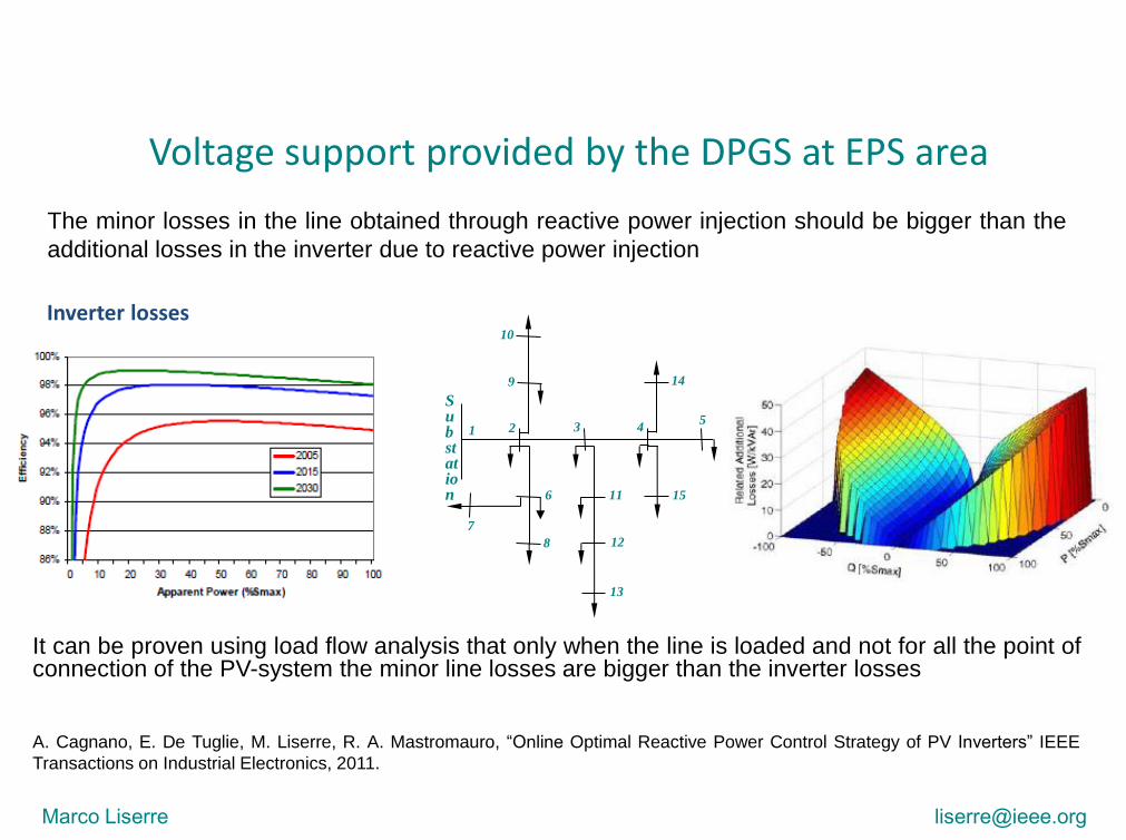
The minor losses in the line obtained through reactive power injection should be bigger than the
additional losses in the inverter due to reactive power injection
Inverter losses
Substation
1
10
2
9
7
6
8
3
11
12
13
4
15
14
5
It can be proven using load flow analysis that only when the line is loaded and not for all the point of connection of the PV-system the minor line losses are bigger than the inverter losses
Voltage support provided by the DPGS at EPS area
A. Cagnano, E. De Tuglie, M. Liserre, R. A. Mastromauro, “Online Optimal Reactive Power Control Strategy of PV Inverters” IEEE
Transactions on Industrial Electronics, 2011.
Marco Liserre [email protected]

Universal inverter
Marco Liserre [email protected]
PMSG
chopR
DCu
DCC
Machine-side
converter
Grid-side
converterS
i
Power
filter
1i 2
i
Machine-side
control
Grid-side
controlUnidirectional
Communication
Link
PCCe
State
Load
UWT1
STS
l 1Z liZ
UWTi UWTN
lNZ
Grid
gZ
PCCe
Circuit
BreakerG
e
State manager
PCCe
State
Unidirectional
Communication
Link
DG
units
State
ISLe

Droop control
2
2
1cos cos sin sin
1cos sin sin cos
P EV E EVZ
Q EV E EVZ
Hypotesis:
1) purely inductive impedance
EVP
X
EQ V E
X
2
sin
cos
EVP
X
EV EQ
X X
2) small
Aim: to allow different sources, in a microgrid, sharing the load without a centralized
control and without communication
Marco Liserre [email protected]

Droop control
Marco Liserre [email protected]
GP
max
min
0
WTP
ZoneZone
EMEMa Eb Mcf f f
Generous Selfish2
GaP
GbP
GcP
1
GaP
GbP
GcP
Active and reactive power sharing can be tuned for each individual DER
deciding if the contribution should be more or less generous

dtPPnPPm pp )()( ***
dtQQnQQmVV qq )()( ***
PI Controller
)(1
)( *** PPs
nPPm pp a
)(1
)( *** QQs
nQQmVV qq a
Fractional PI Controller
In order to obtain low steady-state error and fast dynamic response without coupling between P and Q, it
can be demonstrated that active and reactive power regulation can be performed by PI controllers. It
results:
Droop control
Marco Liserre [email protected]

Power Decoupling
To obtain Pc and Qc it is sufficient to know the ratio R/X.
sin cos
cos sin
arctan( )
C
C
X R
P P P PZ ZT
Q Q Q R X Q
Z Z
X R
sinC
EVP
Z
2cosC
EV EQ
Z
If the line it is not purely inductive
Marco Liserre [email protected]

Universal Power control
Marco Liserre [email protected]
Tra
nsfo
rma
ntio
n
ma
trix
TD
ST z
z 1
F z
F z
Pfk
PVk
V
GQ
GQ
GQ
GFQ
GFP
GP
GP
GP
GP
GQ
d
C
d
CV
V
S
S
z 1
T zDfk
ST z
z 1IVk
S
PCC
PCCE
S
S
S
S
PCCE
ST z
z 1PCC
S
PCC
(A)
(B)
(C)
(D)
baseV
base
PLANT

Voltage and current control alternatives

Marco Liserre [email protected]
1
f fR sL
1
fsC
2 2
1
R sL2i
e
2i
Cv
Cv1i Ciu
Cv
1i
Ci
ZOHController
PLANT
The voltage control regulates the voltage across the capacitor to implement the droop characteristic
As it is disposed in cascade with the droop control, its response time must be small enough to neglect their coupling
Analysis of most suitable voltage technique involves:
• Single-loop vs. Multi-loop
• Inductor current vs. capacitor current feedback
• Grid-connected and stand-alone operation modes
• LC-resonance damping, time response, perturbation and switching noise rejection, discrete time domain, harmonic rejection, etc
Introduction

Single-loop: P + Resonant and virtual impedance
e
*Cv
Cv
Cv-1z
*u
VZ z2i
PLANTP
RES
Voltage Controller
Less sensors.
Trade-off between performance and stability.
Virtual impedance loop, only activated when grid-connected to cancel the most representative current harmonics.
C5
L5
C7
L7
C13
L13i2
2
5,7,11,13 1
n
V Zv
n n n
L sZ z ZOH k
L C s
Marco Liserre [email protected]
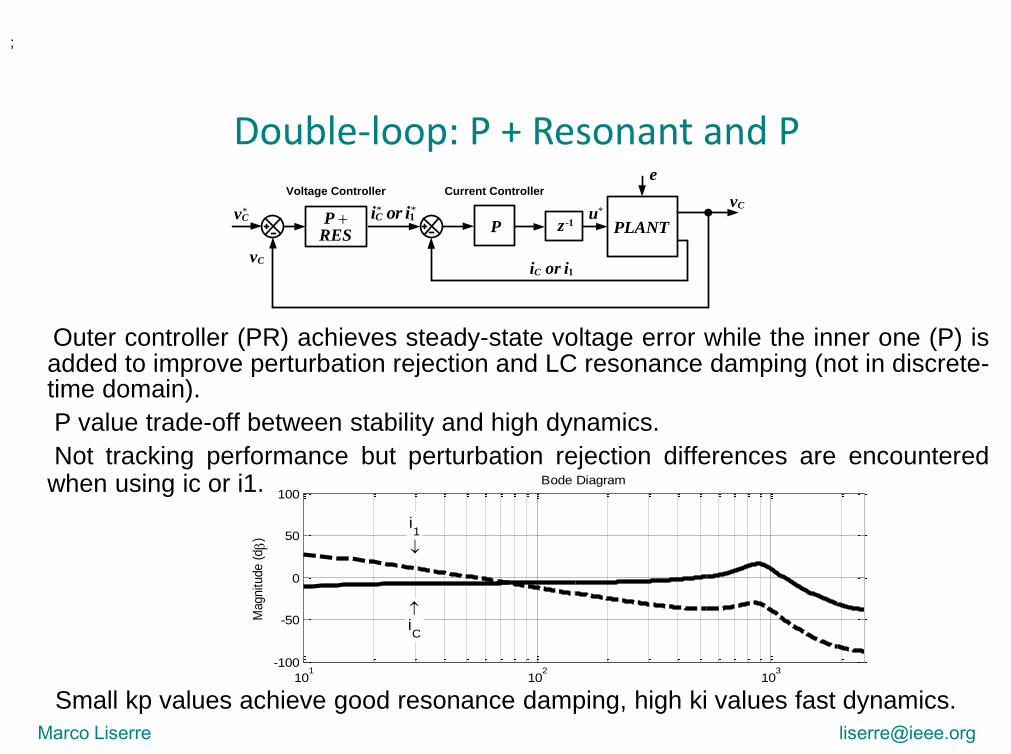
Double-loop: P + Resonant and P
Outer controller (PR) achieves steady-state voltage error while the inner one (P) is added to improve perturbation rejection and LC resonance damping (not in discrete-time domain).
P value trade-off between stability and high dynamics.
Not tracking performance but perturbation rejection differences are encountered when using ic or i1.
Small kp values achieve good resonance damping, high ki values fast dynamics.
;
101
102
103
-100
-50
0
50
100
i1
iC
Magnitude (
db
)
Bode Diagram
e
*Cv
Cv
Cv
-1z*u
PLANTP
RES
1Ci or i
* * 1Ci or iP
Voltage Controller Current Controller
Marco Liserre [email protected]
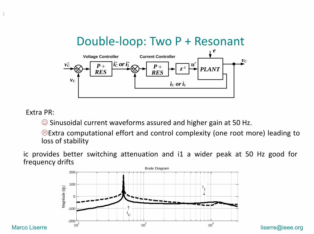
Double-loop: Two P + Resonant
Extra PR:
Sinusoidal current waveforms assured and higher gain at 50 Hz.
Extra computational effort and control complexity (one root more) leading to loss of stability
;
e
*Cv
Cv
Cv
-1z*u
PLANTP
RESP
RES
1Ci or i
* * 1Ci or i
Voltage Controller Current Controller
101
102
103
-200
-100
0
100
200
i1
iC
Mag
nitu
de (
db
)
Bode Diagram
ic provides better switching attenuation and i1 a wider peak at 50 Hz good for frequency drifts
Marco Liserre [email protected]

Comparison ;
Marco Liserre [email protected]
101
102
103
-5
-2.5
0
2.5
5
Frequency (Hz)
Magnitude of the Sensitivity Transfer Function S(Z) (db)
SL
PR+P iC
PR+P i1
PR+PR iC
PR+PR i1
1 5 10 50 100-30
-20
-10
0
10
20
Frequency (Hz)
a) |Z0| (db)
1 5 10 50 100
-300
-200
-100
0
Frequency (Hz)
b) Angle of Z0 (º deg)
SL
PR+P iC
PR+P i1
PR+PR iC
PR+PR i1
0 0.2 0.4 0.6 0.8 1
-0.6
-0.4
-0.2
0
0.2
0.4
0.6
0.8
Imag
inar
y ax
is
Real axis
24kW
24kW
6kW
6kW
24kW
24kW
6kW6kW
SL
PR+P iC
PR+P i1
PR+PR iC
PR+PR i1
-1 -0.8 -0.6 -0.4 -0.2 0 0.2 0.4 0.6
-1
-0.8
-0.6
-0.4
-0.2
0
0.2
0.4
0.6
0.8
1
d1
d2
d3
d4
d5
Re[L(z)]
Im[L
(z)]
SL
PR+P iC
PR+P i1
PR+PR iC
PR+PR i1
Grid-connected
Island mode
;
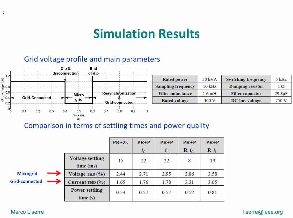
Grid voltage profile and main parameters
Comparison in terms of settling times and power quality
Microgrid
Grid-connected
Marco Liserre [email protected]
Simulation Results

Harmonic rejection

Universal Harmonic Rejection
*
11
2 23
( )
2( )
2
ref Ci H Ci
i
H
i i iodd
v v Z s i
K sZ s
s K s
In grid-connected: harmonic-free current into the grid
Current harmonics compensation loop
Voltage harmonics compensation loop
Marco Liserre [email protected]
In island operation mode the aim of the control is to supply
the loads with sinusoidal voltage in spite of non-linear or
unbalanced loads
The proposed control strategy allows to modify the inner
loops control structure when the islanding is detected, in
particular the resonant compensators can be applied in the
voltage control loop without changing the voltage reference

Simulation Results
Harmonic compensation strategy in grid-connected operation mode
Marco Liserre [email protected]

Simulation Results Harmonic compensation strategy in island operation mode
Marco Liserre [email protected]

Experimental Results Current harmonic compensation
The current presents a low distortion, since the
THD is reduced from 6% to 2% .
Marco Liserre [email protected]

Transition among different operation modes

Three operation modes: Grid-Connected, Stand-Alone or Synchronization.
S=1: The system is synchronized (Synch=1)and there is not any islanding condition (AI=1).
S=2: A islanding conditions has been detected (AI=0) and circuit breaker 2 is disconnected, hence, Vpcc and Vpcc1 are not synchronized (Synch=0). Integrators of droop controller are disabled.
S=3: The islanding conditions is cleared (AI=1) but the system is not synchronized with the grid yet (Synch=0). wt and E and are the phase and amplitude of Vpcc1, but the output of PI_P and PI_Q are not supplied in this state. When the system is synchronized again, the output of the integral part are reset.
Universal droop control
Marco Liserre [email protected]

f and V
measurements
Inject
Start
Island
AI=1
Inject
or
maxf f
maxV V
AIf f AIV V
islP islQ
No
No
No
Yes Yes
Yes
( )·
( )·
isl fP AI
isl VQ AI
P K f sign f f
Q K V sign V V
rated
rated
f f f
V V V
Anti-islanding method.
Active method based on the positive feedbacks of active and reactive power.
Synchronization system.
2 PLLs and 2 buffers that monitor amplitude and phase of Vpcc and Vpcc1.
When the phase and amplitude differences remain lower than certain thresholds, the synchronization is finished.
Universal droop control
Marco Liserre [email protected]

Grid-connectedStand-
AloneGrid-Connected
Synchronization
0 5 10 15 20 25 30-15
-10
-5
0
5
10
Act
ive
(kW
) an
d R
eact
ive(
kVA
r)po
wer
tran
sfer
Time (s)
P
Q
Pload=10kW Qload=0VAr P*=10kW Q*=0Var
9.96 9.98 10 10.02 10.04 10.06-500
0
500
Volta
ges in
PC
C (
V)
a)
Vpcc
a
Vpcc1
a
9.96 9.98 10 10.02 10.04 10.06-0.5
0
0.5
1
1.5
Contr
ol s
ignals
d)Time(s)
AI
Synch
9.96 9.98 10 10.02 10.04 10.060
200
400
Am
plit
ude
of V
pcc1 (
V)
b)
9.96 9.98 10 10.02 10.04 10.0620
40
60
Fre
quency
of V
pcc1 (
Hz)
c)14.8 14.9 15 15.1 15.2 15.3 15.4
-500
0
500
Vol
tage
s in
PC
C(V
)
a)
Vpcc
a
Vpcc1
a
14.8 14.9 15 15.1 15.2 15.3 15.4-0.5
0
0.5
1
1.5
Con
trol
sig
nals
b)Time (s)
AI
Synch
Islanding detection
Re-synchronization.
Marco Liserre [email protected]
Simulation Results

Pload=10kW Qload=2VAr P*=10kW Q*=0Var
1.9 1.95 2 2.05 2.1-400
-200
0
200
400
Volta
ges in
PC
C
Vpcca
Vpcc1a
1.9 1.95 2 2.05 2.1-0.5
0
0.5
1
1.5
Contr
ol s
ignals
Time (s)
AI
Synch
2.4 2.45 2.5 2.55 2.6 2.65 2.7 2.75 2.8-400
-200
0
200
400
Volta
ges in
PC
C
Vpcca
Vpcc1a
2.4 2.45 2.5 2.55 2.6 2.65 2.7 2.75 2.8-0.5
0
0.5
1
1.5
Contr
ol s
ignals
Time (s)
AI
Synch
Marco Liserre [email protected]
Simulation Results

Pload=10kW Qload=-2VAr P*=10kW Q*=0Var
1.9 1.95 2 2.05 2.1-400
-200
0
200
400
Volta
ges in
PC
C
Vpcca
Vpcc1a
1.9 1.95 2 2.05 2.1-0.5
0
0.5
1
1.5
Contr
ol s
ignals
Time (s)
AI
Synch
2.4 2.5 2.6 2.7 2.8-400
-200
0
200
400
Volta
ges in
PC
C
Vpcca
Vpcc1a
2.4 2.5 2.6 2.7 2.8-0.5
0
0.5
1
1.5
Contr
ol s
ignals
Time (s)
AI
Synch
Marco Liserre [email protected]
Simulation Results

Advanced control options: fractional PI

Fractional PI The generic fractional PI order system representation in the Laplace domain is given as
n
m
sasa
sbsbsb
sX
sYsG
n
m
aa
bbb
.....1
.....
)(
)(1
10
1
10
Where:
• b0, b1, ......, bm and a1, a2, ......, an are constant model parameters or model coefficients;
• β0<β1<…<βm and α1<α2< ..... <αn are the fractional powers or fractional orders
The main idea is to develop a functional operator PI, associated to an order α not restricted to
integer numbers, that generalizes the usual notions of integrals. The transfer function of a
fractional PI is given by
aasT
KsGi
P
11
Where:
• Kp is the proportional constant,
• Ti is the constant time integrator;
• α is the fractional PI order α
=1
<1
PI controller
Fractiponal PI controller
Marco Liserre [email protected]

Tuning of the fractional PI in the droop control loop
Assuming a P/Q decoupling and modeling the low-pass filters with a first-order approximation, the
active and reactive power, given by one inverter, can be derived as:
fpfp
f
c
c PPs
nPPmX
EVPP
sP **
*1)(
)( a
fqfq
f
c
c QQs
nQQmX
EEVQQ
sQ **
*1))((
)( a
Marco Liserre [email protected]

Tuning of the fractional PI in the droop control loop
ACTIVE POWER
(P)
REACTIVE
POWER (Q)
Fractional PI order (α) 1 < αp < 0.3; 1 <αq< 0.3
Proportional constant (Kp) 0.000009 0.009
Constant time integrator
(Ti) 20 200
Bode diagram of active power Bode diagram of reactive power
Marco Liserre [email protected]

Simulation Results
Active power Reactive power
variation of
load
power request
by the load
power supply
by the inverter
Marco Liserre [email protected]

Experimental results
Fractional PI controller PI controller
Where:
CH3: Converter current; CH1grid-voltage; CH4 inverter voltage output.
single inverter in
grid-connected
operation mode
two inverter in
grid-connected
operation mode
Marco Liserre [email protected]

Universal Operation of Wind Turbine Systems without Storage

Marco Liserre [email protected]
The kinetic storage of the UWT together with a suitable control strategy can be used to operate the UWT in island mode for a certain time without any additional storage
Statistical assessment of the power reliability improvement shall be done by means of SIER
Introduction
Wind
turbineRotor
DC-link
capacitors
Aerodynamic
losses
Mechanical
losses
Generator
and switching
losses
Switching and
filter losses
Injected
power
Generated
powerWind
Power
Kinetic stored
energy
MPPT LOSSES
LOADb )
)
P
a P P
WT MPPT
WTb
) P P
) P
a
WT LOAD LOSSESb )
a )
P ( P P )
0
a )Grid connec
b ) Is
te
d
d
lan
Chopper
losses
0 10 20 30 40 500
5
10
15
20
Power (kW)
Pro
bab
ilit
y (%
)
Generation
Load P1
=15 kW
Load P2
=20 kW
Load P3
=25 kW
Load P4
=30 kW
Load P5
=35 kW
Load P6
=40 kW

Marco Liserre [email protected]
Depending on the steady-state operation mode the different curves for the generation control can be sketched
Calculation of SIER
0 5 10 15 20 250
0.2
0.4
0.6
0.8
1
Wind speed (m/s)
Per
uni
t va
lues
I IIIII
Power
CP
Torque
Rotor Speed
Pitch Angle
Depending on the load and on the island operation time different interruption times can be calculated
0 5 10 15 20 250
10
20
30
40
50
60
Time (s)
Pro
bab
ilit
y (%
)
tSD
@ P1
= 15 kW
tSD
@ P2
= 20 kW
tSD
@ P3
= 25 kW
tSD
@ P4
= 30 kW
tSD
@ P5
= 35 kW
tSD
@ P6
= 40 kW
tINT
@ T1
= 10 s
tINT
@ T2
= 2 min
tINT
@ T3
= 10 min
0
10
20
30
40
50
60
0 5 10 15 20 250
10
20
30
40
50
60
Time (s)
Pro
bab
ilit
y (%
)
tSD
@ P1
= 15 kW
tSD
@ P2
= 20 kW
tSD
@ P3
= 25 kW
tSD
@ P4
= 30 kW
tSD
@ P5
= 35 kW
tSD
@ P6
= 40 kW
tINT
@ T1
= 10 s
tINT
@ T2
= 2 min
tINT
@ T3
= 10 min
0
10
20
30
40
50
60

Marco Liserre [email protected]
UWT can be used to reduce the average interruption time
The reduction in the average interruption time obtained by means of the Universal Operation is quite remarkable, being at least 22.27 % and 60.5 % in the best case
Calculation of reduction of interruption time
'Tμ (s)
Average Load Consumption
P1μ P2μ P3μ P4μ P5μ P6μ
Ave
rag
e
Inte
rru
pti
on
Du
rati
on
T 1μ 3.95 4.64 5.26 5.69 6.19 6.52
T 2μ 62.50 71-02 78.32 83.37 87.82 91.59
T 3μ 321.83 364.82 401.08 427.83 446.63 466.39

Conclusions
Universal operation of power converters is needed in the future distribution
grids characterized by frequent disconnection and operation in island mode
Major challenges are in low voltage distribution lines because of not negligible
resistive nature and of similar time constants of different control loops
Many different options exist for the internal control loops (current and voltage)
and they have been reviewed also considering harmonic control
Fractional control can make easier to tune power controllers that should work
in very different operational modes (grid-connected and island)
Universal Operation without added storage is feasible and can lead to reduce
the interruption time
Marco Liserre [email protected]

Publications Remus Teodorescu, Marco Liserre, Pedro Rodriguez “Grid Converters for Photovoltaic and Wind Power
Systems”, Wiley-IEEE, ISBN 8-0-470-05751-3, January 2011. 2nd reprint in 9 months. Translated in
Chinese 2012.
Mario Rizo, “Universal operation of small wind turbine systems”, University of Alcala de Henares, Spain,
2013.
M. Rizo, M. Liserre, E. Bueno, F. J. Rodríguez, F. Huerta, “Universal wind turbine working in grid-connected
and island operating modes”, Mathematics and Computers in Simulation, Elsevier, 2012.
M. Liserre, A. Nagliero, R. A. Mastromauro, N. A. Orlando, D. Ricchiuto, A. Altomare, M. Nitti, A. Dell’Aquila
“Universal operation of small and medium size Renewable Energy Systems” invited paper at PEIA 2011,
Doha, Qatar.
M. Rizo, M. Liserre, E. Bueno and F.J. Rodríguez “Universal wind turbine working grid-connected and
stand-alone”, Electrimacs 2011.
D. Ricchiuto, M. Liserre, R. Mastromauro, A. Dell’Aquila, A. Pigazo, “Fractional-Order Based Droop Control
Of An Universal Wind-Turbine System”, EPE 2011.
M. Rizo, E. Bueno, A. Dell’Aquila, M. Liserre, R. A. Mastromauro “Generalized Controller for Small Wind
Turbines Working Grid-Connected and Stand-Alone”, ICCEP 2011, Ischia.
A. Nagliero, R. A. Mastromauro, D. Ricchiuto, M. Liserre, M. Nitti, “Gain-scheduling-based Droop Control for
Universal Operation of Small Wind Turbine Systems”, ISIE 2011, Gdansk, Poland.
A. Nagliero, R. A. Mastromauro, D. Ricchiuto, M. Liserre, “Harmonic Control Strategy for Universal
Operation of Wind Turbine Systems” Powereng 2011, Malaga, Spain.
A. Nagliero, R. A. Mastromauro, V.G. Monopoli, M. Liserre, A. Dell’Aquila, “Analysis of a universal inverter
working in grid-connected, stand-alone and micro-grid” ISIE 2010, Bari.
A. Nagliero, A. Lecci, R. A. Mastromauro, M. Liserre, A. Dell'Aquila, "Particle Swarm Optimization of a
universal inverter," IECON 2010 - 36th Annual Conference on IEEE Industrial Electronics Society , vol., no.,
pp.199-204, 7-10 Nov. 2010
Marco Liserre [email protected]

Acknowledgment The work has been developed in close cooperation with
and in particular with Prof. Emilio Bueno and PhD student Mario Rizo
Marco Liserre [email protected]
GEISER:
Group of Electronics Engineering Applied
to Renewable Energy Systems Department of Electronics
Alcalá University (Spain)
http://geiser.depeca.uah.es/