Embed Size (px)
Citation preview

Fire Protection(UL/FM) Certifi ed Products
AWWAWaterworks Products
UNITED WaterProducts
WARNING:These products can expose you to chemicals including lead, which is known to the State of California to cause cancer and birth defects or other reproductive harm. For more information go to www.P65Warnings.ca.gov.

Non Rising Stem Valve
Model 1010 (2”~48”)Resilient Seat Gate ValveNon Rising Stem
Description:1. Conforms to AWWA C515, MSS-SP-702. Fusion Bonded Epoxy Coated Interior and Exterior, AWWA C550. Epoxy Powder Certifi ed to NSF-61.3. 2” square nut or optional handwheel at customer’s request.4. Open right valves supplied with red operating nut.5. Temperature: 2°C (35°F) to 82°C (180°F)6. Working Pressure: 3”~24” - 250 psi - 30”~48” - 150 psi7. Conforms with the U.S. Safe Drinking Water Act (Lead Free)
Model 2010 (Size 2”~24”)Resilient Seat Gate ValveNon Rising Stem2010-B with Bevel Gear Operator2010-S with Spur Gear Operator
Available:MJ x FlangeFlange x FlangeMJ x MJMJ X Tapping FlangeDescription:1. Conforms to AWWA C515-092. MJ dimensions conform to AWWA C153.3. Flange dimensions conform to ANSI B16.1 Class 1254. Fusion Bonded Epoxy Coated Interior and Exterior to AWWA C550 Standard. NSF-61 Certifi ed.5. 2” Square Operating Nut provided. Color coded black (open right valves provided with RED operating nuts) or optional handwheel at Customer’s request.6. Working Pressure: UL/FM rated working pressure: 2-1/2”~12” - 300 psi UL/lFM rated working pressure: 14”~16” - 250 psi UL rated working pressure: 18” - 250 psi UL rated working pressure: 20” & 24” - 200 psi FM rated working pressure: 18”~24” - 200 psi 7. Temperature: -23°C (-10°F) to 110°C (230°F)8. Conforms with the U.S. Safe Drinking Water Act (Lead Free)
2~1/2”- 24”
Model 2010-PIV (Size 4”~24”)Post Indicator ValveResilient SeatNon Rising Stem2015-S with Spur Gear Operator
Description:1. Conforms to AWWA C515-092. MJ dimensions conform to AWWA C153.3. Flange dimensions conform to ANSI B16.1 Class 125.4. Fusion Bond Epoxy Coated Interior and Exterior to AWWA C550 Standard. NSF-61 Certifi ed.5. 2" Square Operating Nut provided. Color coded black. (open right valves provided with RED operating nuts).6. Compatible with all industry standard Vertical Indicator Posts, NFPA 24.7. Working Pressure: UL/FM rated working pressure: 4”~12” - 300 psi UL/FM rated working pressure: 14”~16” - 250 psi UL rated working pressure: 18 - 250 psi UL rated working pressure: 20” & 24” - 200 psi FM rated working pressure: 18”~24” - 200 psi8. Temperature: -23°C (-10°F) to 110°C (230°F)9. Conforms with the U.S. Safe Drinking Water Act (Lead Free)
Available:MJ x MJFlange x FlangeMJ x Flange
4”- 24”
4”- 24”
OS&Y Gate Valves
Model 2030 (Size 2”~24”)Resilent Seat Gate ValveOS&Y2030-B with Bevel Gear Operator
Description:1. Conforms to AWWA C515-092. Epoxy coated inside and outside to AWWA C550.3. Working Pressure: UL/FM rated working pressure: 2”~12” - 300 psi. UL/FM rated working pressure: 14”~16” - 250 psi. UL rated working pressure: 18” - 250 psi FM rated working pressure: 18” & 24”: - 200 psi UL rated working pressure: 20”~24” - 200 psi.4. Temperature: -23°C (-10°F) to 110°C (230°F)5. Flanged ends conform to ANSI B16.1 standard.6. Grooved ends conform to AWWA C606 standard.
Available:Flange EndsGrooved EndsFlange x Groove
2”- 24”
2-1/2”- 24”
2”- 12”
14”- 24”
ear Operator
2”- 12”
2”- 24”
2”- 16”
Available:MJ x FlangeFlange x FlangeMJ x MJ

Model 8700-F (Size 2”~12)Resilient Seat Check ValveFlanged EndsANSI 125 lb. Body
Check Valves
Model 7700 (Size 2”~24”)Resilient Seat Check ValveANSI 125 lb. Body7700 (without lever, weight or spring)7700-LW (with lever & weight)7700-LS (with lever & spring)
Description:1. Flange drilling and dimensions to ANSI B16.1, 125 lb. pattern.2. End to end dimensions (Laying Length) to AWWA C-508 Standard for Clear Waterway Swing Check Valves3. Maximum working pressure: 200 psi.4. Suitable for Water / Sludge / Sewage service5. Fusion Bonded Epoxy Coated Interior and Exterior to AWWA C550. Powder Certifi ed to NSF-616. Installed with standard fl ange accessories (AWWA C110).7. Conforms with the U.S. Safe Drinking Water Act (Lead Free)
Description:1. Flange drilling and dimensions to ANSI B16.1, 125 lb. pattern.2. Face to face dimensions conform to AWWA C508, Full Waterway3. Maximum Working Pressure: 300 psi4. Fusion Bonded Epoxy Coated, Interior and Exterior, to AWWA C550.
2”~12”
2”~12”
Model 8700-G (Size 2”~12)Resilient Seat Check ValveGrooved EndsANSI 125 lb. Body
Description:1. Groove dimensions comply with AWWA C606 standard.2. Maximum Working Pressure: 300 psi3. Working Temperature: -10°C to 120°C for EPDM -10°C to 82°C for NBR4. Fusion Bonded Epoxy Coated, Interior and Exterior to AWWA C550.
2”~12”
2”~12”
Model 5400Vertical Indicator Postw/Adjustable Bury Length
Specifi cations:1. Indicates if the valve is in the open or shut position.2. The indicator post provides a means to operate a buried or otherwise inaccessible valve.3. The adjustment range of the indicator post is 34.5” to suit the deeper buried valve and can be easily adjusted in the fi eld.4. The wrench handle fi ts over a “U” bracket on the barrel, and may be fi xed with a padlock to secure the opera- tion wrench to the barrel.5. Can be supplied to open left or right.
Model 5400For use with valves sizes 4”~16” (UL/FM Approved)
Model 5500Wall Indicator Post
Specifi cations:1. Indicates if valve is in open or shut position2. Used to operate a valve installed behind a wall, with a 12” OD post fl ange to mount on a wall3. Operated by handwheel4. Can be supplied to open left or right5. UL Listed and FM Approved.
Indicator PostsModel 5450Vertical Indicator PostWith Integral Reduction Gearand Adjustable Bury Length
Model 5450For use with valve sizes 14”~24” (UL Listed)
4”- 14”
4”- 12”

Check Valves (Cont.)
Model 2560 (Size 2”~16”)Wafer Double Door Check Valve
2”- 16”
Description:1. Extremely short face to face dimensions and compact design allows for installation and service in tight spaces.2. Spring assisted for better dynamic behavior.3. Soft seated for perfect tightness even at low diff erential pressure.4. Flanged ends conform to ANSI B16.1 Class 1255. Working Pressure: 300 psi6. Temperature: -10° to 120°C7. Internally and externally spray painted or fusion bonded epoxy powder coated (FBE).8. Stainless steel disc for excellent corrosion resistance.9. Horizontal or vertical installation
Model 9600 (Size 2”~24”)Resilient Disc Check ValveFlanged Ends
Butterfl y Valves
Description:1. The disc is precision molded with an integral O-ring type sealing surface, and contains alloy steel with nylon reinforcement in the fl exible hinge area.2. Manufactured with threaded port and a pipe plug on the bottom of the valve to allow for fi eld installation of a back fl ow actuator.3. Slamming and water hammer virtually non-existent due to it’s short closing travel.4. Full top-entry access for easy on-line inspection and maintenance.5. Working Pressure: 250 psi/16 Bar 6. Working Temperature: -10°C to 82°C for NBR coated trim -10°C to 150°C for EPDM coated trim (optional)7. Flange drilling to: ANSI 125/150 or EN1092-2 PN10 or PN16.8. Internally and externally fusion bonded epoxy powder coated (FBE).9. Manufactured in accordance with AWWA C508, MSS-SP-71.
Model 2400-G (Size 2”~12”)Grooved Butterfl y ValveManually Gear Operated with Tamper Switch
Model 2400-W (Size 2”~12”)Wafer Butterfl y ValveManually Gear Operated with Tamper Switch
2”~12”
NSF61NSF372
2”~12”
NSF61NSF372
Description: 1. Design Standard: MSS-SP-67 2. EPDM Encapsulated ductile iron disc for bubble-tight shut off 3. Flag type position indicator 4. Low torque operation 5. High cycle life 6. Built-in supervisory switch 7. Top fl ange to ISO 5211/1 8. Groove Dimension in accordance with AWWA C606 9. Working Pressure: 2”~12”: 300 psi 10. Working Temperature: 33°F to 176°F (0°C to 80°C) 11. Fusion bonded epoxy powder coated to AWWA C550. 12. UL Listed / FM Approved for indoor or outdoor use.
Description: 1. Design Standard: MSS-SP-67 / API-609 2. EPDM Encapsulated ductile iron disc for bubble-tight shut off 3. Flag type position indicator 4. Low torque operation 5. High cycle life 6. Built-in supervisory switch 7. Top fl ange to ISO 5211/1 8. Flange connection to ANSI B16.1 Class 125/ANSI B16.5 Class 150 9. Working Pressure: 2”~8”: 300 psi, 10” & 12”: 250 psi 10. Working Temperature: 33°F to 176°F (0°C to 80°C) 11. Fusion bonded epoxy powder coated to AWWA C550. 12. UL Listed / FM Approved for indoor or outdoor use.
Model 2400-L (Size 2”~12”)Lug Butterfl y ValveManually Gear Operated with Tamper Switch
NSF61NSF372
Description: 1. Design Standard: MSS-SP-67 & API 609 2. EPDM Encapsulated ductile iron disc for bubble-tight shut off 3. Flag type position indicator 4. Low torque operation 5. High cycle life 6. Built-in supervisory switch 7. Top fl ange to ISO 5211/1 8. Flange connection to ANSI B16.1 Class 125/ANSI B16.5 Class 150 9. Working Pressure: 2”~8”: 300 psi, 10” & 12”: 250 psi 10. Working Temperature: 33°F to 176°F (0°C to 80°C)11. Fusion bonded epoxy powder coated to AWWA C550.12. UL Listed / FM Approved for indoor or outdoor use.

Butterfl y Valves (Cont.)
Model 3900 (Size 3”~24”)Butterfl y ValveManually Gear OperatedAvailable:Flange x FlangeMJ x MJ
Description:1. Design Standard: AWWA C5042. Flange ends to ANSI B16.1 Class 125. Other fl ange types are available.3. Mechanical Joint Ends to AWWA/ANSI C153/A21.53.00.4. Top Flange complies with ISO 5211/1.5. Operator: Manual Gear Operator w/wheel handle (shown) Manual Gear Operator w/2” Square AWWA Nut6. Working Pressure: 250 psi7. Working Temperature: EPDM: 14°F to 248°F (-10°C to 120°C) NBR: 14°F to 180°F (-10°C to 80°C)
Model 2400-T (Size 1”~2”)Threaded Butterfl y ValveManually Gear Operated with Tamper Switch
Description:1. Manufactured in accordance to UL 1091, UL38 & UL753 standards.2. Threaded Ends: In Accordance with ASME B1.20.1 3. Fusion Bond Epoxy Coated 4. Working Temperature: 0°C ~ 80°C5. Working Pressure: 175 psi/12 Bar/non-shock cold water6. Fire Protection Valve - Full Port Design
y
NSF61NSF372
Model 1410-G1 (Size 2”~12”)Grooved Butterfl y Valve with Lever
Description:1. Standard: MSS SP-672. Connection Ends: Groove to AWWA C6063. Top Flange Standard: ISO 52114. Fusion Bonded Epoxy Coated to AWWA C5505. 10 position lever handle. 6. Working Temperature: 0°C~100°C (32°F~212°F)7. Working Pressure: 300 psi
Model 3420-L-1 (Size 2”~12”)Lug Butterfl y Valve with Lever
Model 3420-L-2 (Size 2”~28”)Lug Butterfl y Valve with Manual Gear Operator
Description:1. Standard: MSS SP-67/API 6092. Connection Ends: Compatible with: ASME B16.1 Class 125 and ASME B16.5 Class 150 Flanges3. Top Flange Standard: ISO 5211 - allows mounting of a variety of actuators4. Fusion Bonded Epoxy Coated to AWWA C5505. 10 position lever handle or Handwheel with Manual Gear Operator. 6. Meets the performance requirements of AWWA C5047. Working Temperature: 0°C~80°C (32°F~176°F)8. Working Pressure: 2”~8” - 300 psi 10”~12” - 250 psi
Model 3420-W-1 (Size 2”~12”)Wafer Butterfl y Valve with Lever
Model 3420-W-2 (Size 2”~12”)Wafer Butterfl y Valve with Manual Gear Operator
Description:1. Standard: MSS SP-67/API 6092. Connection Ends: Compatible with: ASME B16.1 Class 125 and ASME B16.5 Class 150 Flanges3. Top Flange Standard: ISO 5211 - allows mounting of a variety of actuators4. Fusion Bonded Epoxy Coated to AWWA C5505. 10 position lever handle or Handwheel with Manual Gear Operator. 6. Meets the performance requirements of AWWA C5047. Working Temperature: 0°C~80°C (32°F~176°F)8. Working Pressure: 2”~12” - 300 psi
Adapters, Couplings, Reducers, Converters & Restraints
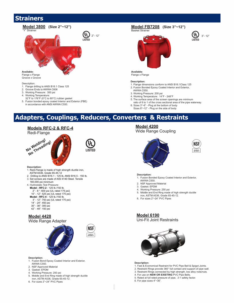
Model 4428Wide Range Adapter
Description:Description:11. Fusion Bond Epoxy Coated Interior and Exterior, AWWA C550.2. NSF Approved Material2. NSF Approved Material3. Gasket: EPDM3. Gasket: EPDM4. Working Pressure: 250 psi4. Working Pressure: 250 psi5. Middle and End Ring made of high strength ductile 5. Middle and End Ring made of high strength ductile iron, ASTM A536, Grade 65-45-12. iron, ASTM A536, Grade 65-45-12.6. For sizes 2”~24” PVC Pipes 6. For sizes 2”~24” PVC Pipes
Model 6190Uni-Fit Joint Restraints
Description:1. Fast & Economical Restraint for PVC Pipe Bell & Spigot Joints.2. Restraint Rings provide 360° full contact and support of pipe wall.3. Restraint Rings connected by high strength, low alloy rods/nuts.4. For use on NEW OR EXISTING PVC Pipe Bells.5. Rated at full rated pressure of pipe, 2:1 safety factor.6. For pipe sizes 4”~36”.
Models RFC-2 & RFC-4Redi-Flange
No Welding!
No Threading!
Description:1. Redi-Flange is made of high strength ductile iron, ASTM A536, Grade 65-45-122. Drilling to ANSI B16.1 - 125 lb, ANSI B16.5 - 150 lb.3. Set screws are made of AISI 4140 Steel. Tensile 160,000 psi minimum4. Hydrostatic Test Pressure: Model - RFC-2 - 125 lb./150 lb. 2” - 8 “: 600 psi (UL rated 175 psi) 10” - 12”: 525 psi (UL rated 175 psi) Model - RFC-4 - 125 lb./150 lb. 3” - 12”: 750 psi (UL rated 175 psi) 14” - 24”: 450 psi 30” - 36”: 300 psi 42” - 48”: 150 psi
Model 4200Wide Range Coupling
Description:Description:11. Fusion Bonded Epoxy Coated Interior and Exterior, AWWA C550.2. NSF Approved Material2. NSF Approved Material3. Gasket: EPDM3. Gasket: EPDM4. Working Pressure: 250 psi4. Working Pressure: 250 psi5. Middle and End Ring made of high strength ductile 5. Middle and End Ring made of high strength ductile iron, ASTM A536, Grade 65-45-12. iron, ASTM A536, Grade 65-45-12.6. For sizes 2”~24” PVC Pipes6. For sizes 2”~24” PVC Pipes
StrainersModel 3800 (Size 2”~12”)“Y” Strainer
Description:1. Flange drilling to ANSI B16.1 Class 1252. Groove Ends to AWWA C6063. Working Pressure: 300 psi4. Working Temperature: 32°F to 176°F (0°C to 80°C) rubber gasket5. Fusion bonded epoxy coated Interior and Exterior (FBE) in accordance with ANSI AWWA C550.
Model FB7208 (Size 3”~12”)Basket Strainer
3”- 12”
Available:Flange x Flange
Description:1. Flange dimensions conform to ANSI B16.1Class 1252. Fusion Bonded Epoxy Coated Interior and Exterior, AWWA C550. 3. Working Pressure: 200 psi4. Working Temperature: 14°F - 248°F5. The surface area of the screen openings are minimum ratio of 6 to 1 of the cross sectional area of the pipe waterway.6. Sizes 3”~6” - Plug at the bottom of body Sizes 8”~12” - Plug on the side of body
2”- 12”
Available:Flange x FlangeGroove x Groove

Flanged Fittings - AWWA C110ElbowsTeesCrossesWyesReducers
Manufactured from high strength ductile iron, our fl anged fi tting series are available in 2”~48” sizes in a variety of elbows, tees, crosses, laterals, reducers, and blind fl anges. All are manufactured in strict accordance with AWWA C110, ANSI A21.10.
1. Material: Ductile Iron, ASTM A536, Grade 65-45-12
2. Flange: Faced and drilled in accordance with ANSI B16.1 Class 125
3. Lining: The standard lining is cement mortar with bitumen overlay (NSF 61) in accordance with AWWA C104, ANSI A21.4. Other optional linings such as fusion bonded epoxy, glass etc., are also available.
4. Coating: The standard coating is a red color, zinc rich primer. Other optional coatings are also available.
5. Pressure Rating: 250 WWP
ElbowsTeesCrossesWyesReducers
Our fl anged fi tting series are available in 2”~24” sizes in a variety of elbows, tees, crosses, laterals, reducers, and blind fl anges. All are manufactured in strict accordance with ANSI B16.1 Class 125 (2”~24”) and Class 250 (3”~12”).
1. Material: Ductile Cast Iron, ASTM A536, Grey Cast Iron, ASTM A-126
2. Flange: Faced and drilled in accordance with ANSI B16.1 Class 125 or Class 250.
3. Coating: Available with special inhibited primers, epoxy and galvanized coating.
Flanged Fittings - ANSI B16.1 Class 125 and Class 250

(Full Face & Ring)• Seal-Tite • Red Rubber• Non-Asbestos
& Rin
Flange Gaskets (2”~48”)
Flange Accessories
Stud Bolts & Nuts (2”~48”)
Finishes:• Zinc Plated• Hot dipped galvanized• Fluorocarbon
Materials:• A307 A Carbon Steel• A307 B Carbon Steel• SS304 Stainless Steel• SS316 Stainless Steel
Packaged Bolt Packs (2”~48”) (2 48 )Flange Accessory Packs
(2”~48”)
Series #840 - Flange Converter Class 125/150 & Class 250/300 - This proprietary product allows the conversion of existing Class 250/300 fl anged pumps, valves, etc. to a Class 125/150 fl ange system without the use of fabricated transition spools. Sizes range from 3”~12”.
Specialty FlangesSeries #740 (Type A) & 790 (Type B) - Compact Flange ReducerThese reducers will mate with Class 125/150 fl anges, allowing a reduction of fl ange sizes in a relatively small space. For example, a 6” x 3” reduction is made with only 1-1/2” wide space and a 16” x 12” only requires 2-1/2”. Sizes range from 2” x 1-1/2” to 16” x 14”..

Mechanical Joint Fittings - AWWA C153AWWA C153 (ANSI A21.53), Compact Body Ductile Fittings 3” - 48” for water and other liquids
1. Material: Ductile Iron ASTM A536, Grade 65-45-12 or 70-50-5
2. Pressure Rating: 350 PSI Water Working Pressure (Class 350)
3. Testing: 100% Hydrostatic Tested
4. Laying Length: Short body design-straight section of body deleted to provide a more compact and less heavy fi tting without reducing strength or fl ow characteristics.
5. Cement Lining: Interior to AWWA C104 (ANSI A21.4) with bituminous seal coat (NSF 61)
6. Coating: Bituminous in accordance with AWWA C104 (ANSI A21.4)
BendsTeesCrossesWyesReducersCapsPlugs
ucersss
Materials:• Fluorocarbon• Stainless Steel• Kor-10• Anti-Rotation
MJ GlandPacks & Gasket Packs
T-Bolts & Nuts
Type:• Standard• Transition• SDR 35• HDPE
MJ Gaskets & Glands
Mechanical Joint Accessories
1. Gaskets: SBR in accordance with AWWA C111 (ANSI A21.11)
2. T-Bolts: Ductile Iron or Kor-10 Alloy Steel in accordance with AWWA C111 (ANSI A21.11)
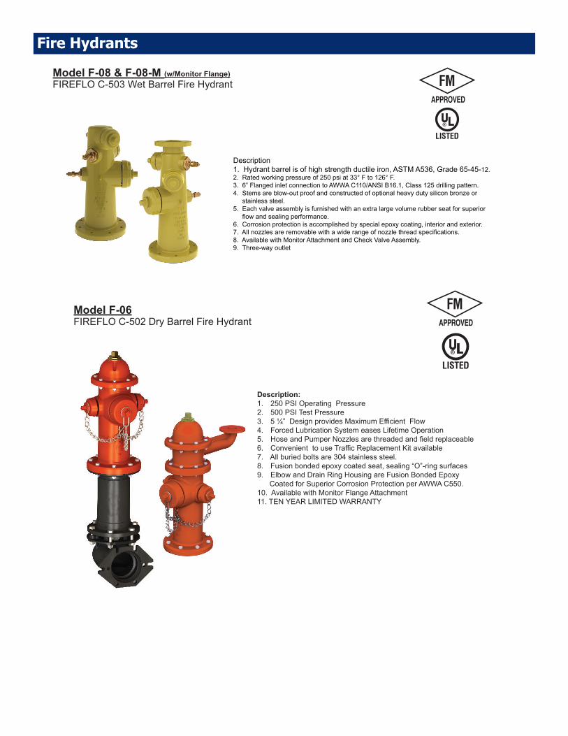
Model F-08 & F-08-M (w/Monitor Flange)FIREFLO C-503 Wet Barrel Fire Hydrant
Description1. Hydrant barrel is of high strength ductile iron, ASTM A536, Grade 65-45-12.2. Rated working pressure of 250 psi at 33° F to 126° F.3. 6” Flanged inlet connection to AWWA C110/ANSI B16.1, Class 125 drilling pattern.4. Stems are blow-out proof and constructed of optional heavy duty silicon bronze or stainless steel.5. Each valve assembly is furnished with an extra large volume rubber seat for superior fl ow and sealing performance.6. Corrosion protection is accomplished by special epoxy coating, interior and exterior.7. All nozzles are removable with a wide range of nozzle thread specifi cations.8. Available with Monitor Attachment and Check Valve Assembly.9. Three-way outlet
Fire Hydrants
Model F-06FIREFLO C-502 Dry Barrel Fire Hydrant
Description:1. 250 PSI Operating Pressure2. 500 PSI Test Pressure3. 5 ¼” Design provides Maximum Effi cient Flow4. Forced Lubrication System eases Lifetime Operation5. Hose and Pumper Nozzles are threaded and fi eld replaceable6. Convenient to use Traffi c Replacement Kit available7. All buried bolts are 304 stainless steel.8. Fusion bonded epoxy coated seat, sealing “O”-ring surfaces9. Elbow and Drain Ring Housing are Fusion Bonded Epoxy Coated for Superior Corrosion Protection per AWWA C550.10. Available with Monitor Flange Attachment11. TEN YEAR LIMITED WARRANTY

Fire Hydrants - Tools and Kits
32"
2'-3"Min.
Increased by6" Increments
1"
Model F-06 ToolsUNITED
PART NO.MUELLERPART NO. DESCRIPTION
F-06-311 A-311 Operating Wrench
F-06-317 A-317 Nozzle Lock Tool
F-06-359 A-359 Seat Removal Wrench
F-06-367 A-367 Brass Sleeve
F-06-316 A-316 2-1/2" Nozzle Wrench
F-06-316 A-316 4-1/2" Nozzle Wrench
SAFETY FLANGE REPAIR KITUNITED
PART NO.MUELLERPART NO. DESCRIPTION
F-06-301 A-301 5-1/4” Hydrant - Safety Flange Repair Kit
Consists of Part No’s. F-06-25, F-06-26, F-06-27, F-06-28, F-06-29 & F-06-30
UNITEDPART NO.
MUELLERPART NO. DESCRIPTION
F-06-320-006F-06-320-010F-06-320-016F-06-320-020F-06-320-026F-06-320-030F-06-320-036F-06-320-040
A-320-006A-320-010A-320-016A-320-020A-320-026A-320-030A-320-036A-320-040
6” Long “Extension Kit12” Long “Extension Kit18” Long “Extension Kit24” Long “Extension Kit30” Long “Extension Kit36” Long “Extension Kit42” Long “Extension Kit48” Long “Extension Kit
Consists of Part No’s. F-06-29, F-06-30, F-06-52, F-06-54, F-06-55, F-06-57 & F-06-53
5-1/4” HYDRANT EXTENSION KITS
BONNET REPAIR KITUNITED
PART NO.MUELLERPART NO. DESCRIPTION
F-06-280-355 280355 5-1/4” Hydrant Bonnet Repair Kit
Consists of Part No’s. F-06-3, F-06-5, F-06-6, F-06-10, F-06-12, F-06-51 & Weather Seal
SHOE REPAIR KITUNITED
PART NO.MUELLERPART NO. DESCRIPTION
F-06-280-357 280357(1996 or earlier)
5-1/4” Hydrant Shoe Repair Kit
Consists of Part No’s. F-06-34, F-08-35, F-06-37, F-06-38, F-06-39, F-06-44, F-06-45, F-06-46, F-06-47, F-06-48 and F-06-51
MAIN VALVE REPAIR KITUNITED
PART NO.MUELLERPART NO. DESCRIPTION
F-06-280-359 280359(1996 or earlier)
5-1/4” Hydrant Main Valve Repair Kit
Consists of Part No’s. F-06-39, F-08-43, F-06-44, F-06-45, F-06-46 and F-06-47

United Water Products5355 Ramona Blvd., Jacksonville, FL 32205
TEL. 877-766-4459 FAX: 877-766-4458Website: www.unitedwaterproducts.com
UNITED WaterProducts
0120