Embed Size (px)
Citation preview

(12) United States Patent Sarkisov et al.
BIMORPHIC POLYMERIC PHOTOMECHANICAL ACTUATOR
Inventors: Sergey S. Sarkisov, Huntsville, AL (US); Michael J. Curley, Huntsville, AL (US); Grigory Adamovsky, Solon, OH (US); Sergey S. Sarkisov, Jr., Huntsville, AL (US); Aisha B. Fields, Huntsville, AL (US)
Assignees: Alabama A&M University, Normal, AL (US); The United States of America as represented by the Administrator of the National Aeronautics and Space Administration, Washington, DC (US)
Subject to any disclaimer, the term of this patent is extended or adjusted under 35 U.S.C. 154(b) by 47 days.
Notice:
Appl. No.: 10/714,702
Filed: Nov. 17, 2003
Int. C1. G02F 1/03 (2006.0 1) G02F 11295 (2006.0 1) G02B 26/00 (2006.0 1) H04B 10104 (2006.0 1) B32B 27/00 (2006.0 1) U.S. C1. ...................... 3591244; 3591246; 3591264;
3591224; 3591291; 3591323; 3591847; 3981189; 3981191; 3981140; 3981130; 4281421; 38514; 385115; 385116; 3101330; 3101309; 3101360;
1361246; 2501306
3591246,264,238,224,291,315,323,847; 38514,9, 15, 16; 4281421, 910; 3981189,
3981191,130,140; 3101309,330,360; 1361246; 2501306; 4301254,272.1,531
Field of Classification Search ................ 3591244,
See application file for complete search history
'Ox /21
(io) Patent No.: (45) Date of Patent:
US 6,999,221 B1 Feb. 14,2006
(56) References Cited U.S. PATENT DOCUMENTS
2,341,877 A * 211944 Middleton et al. .......... 4301531 3,091,707 A * 511963 Hutson 3,677,763 A * 711972 De Boer 3,690,882 A * 911972 Przezdziecki ............... 4301254 4,385,798 A * 511983 Yevick .......................... 38514 4,733,561 A 311988 Gilby .......................... 731579 4,802,153 A 111989 Kataoka et al. .......... 369144.12 4,952,787 A 811990 Nakamura et al. ....... 2501201.5 4,969,137 A 1111990 Sugiyama et al. ....... 369144.11 5,050,969 A 911991 Uchino et al. 5,095,515 A 311992 Seaver ......... 5,107,114 A * 411992 Nishioka et al. ............ 2501306 5,202,790 A 411993 Uchino et al. 3591323 5,270,987 A 1211993 Kaku et al. .............. 369113.02 5,383,048 A 111995 Seaver ....................... 3591279
(Continued)
OTHER PUBLICATIONS
Acoustic Transduction Materials and Devices, Jan. 1999 to Dec. 1999, Annual Report vol. 111, Office of Naval Research, Contract No. N00014-96-1-1173, Uchino.
(Continued)
Primary Examiner-Loha Ben (74) Attorney, Agent, or Firm-Waddey & Patterson, P.C.; Howard H. Bayless; Larry W. Brantley
(57) ABSTRACT
A bimorphic polymeric photomechanical actuator, in one embodiment using polyvinylidene fluoride (PVDF) as a photosensitive body, transmitting light over fiber optic cables, and controlling the shape and pulse duration of the light pulse to control movement of the actuator. Multiple light beams are utilized to generate different ranges of motion for the actuator from a single photomechanical body and alternative designs use multiple light beams and mul- tiple photomechanical bodies to provide controlled move- ment. Actuator movement using one or more ranges of motion is utilized to control motion to position an actuating element in three dimensional space.
83 Claims, 8 Drawing Sheets
F 9 5
https://ntrs.nasa.gov/search.jsp?R=20080008709 2018-05-23T05:01:29+00:00Z

US 6,999,221 B1 Pane 2
U.S. PATENT DOCUMENTS
5,502,781 A 311996 Li et al. ........................ 38514 5,585,961 A 1211996 Saitoh et al. ............... 3591323 5,687,155 A 1111997 Fukakusa et al. ...... 3691112.06 5,757,758 A 511998 Yagi et al. ............. 3691112.25 5,774,259 A 611998 Saitoh et al. ............... 3591315 5,903,380 A * 511999 Motamedi et al. .......... 3591224 6,014,477 A 112000 Barber et al. ................. 385116 6,095,351 A 812000 Rossler ................... 213175 TC 6,125,087 A 912000 Ohnishi et al. .......... 369144.23 6,152,181 A 1112000 Wapner et al. .............. 1371807 6,297,579 B1 * 1012001 Martin et al. ............... 3101330 6,342,671 B1 112002 Morikawa et al. .......... 1361246
6,392,777 B1 512002 Elliott et al. ................ 3591244 6,423,412 B1 * 712002 Zhang et al. ............... 4281421 6,513,939 B1 * 212003 Fettig et al. ................ 3591847
OTHER PUBLICATIONS
Recent Topics of Ceramic Actuators-How to Develop New Ceramic Devices, Ferroelectrics, 1989, vol. 91, pp. 281-292, Uchino. All-optical devices in polymer optical fiber, Chemical Phys- ics 245 (1999) 533-544, Kuzyk, et al.
* cited by examiner

U S . Patent Feb. 14,2006 Sheet 1 of 8 US 6,999,221 B1
20,60,61-,
30 F
21 A
6ZA 63 --
/-2'
1-69 4-64
$lo
75' FIG 1
'Ox
50 \40
FIG 2

U S . Patent Feb. 14,2006 Sheet 2 of 8 US 6,999,221 B1
71 I
20,24
54,50,51,
43
48'
FIG 3
41,42,43
FIG 4

U S . Patent Feb. 14,2006 Sheet 3 of 8
FIG 5
X j - Y
US 6,999,221 B1
51,52
5
FIG 6

U S . Patent Feb. 14,2006 Sheet 4 of 8
I-
30 -+
US 6,999,221 B1
‘1 50 40
FIG 7a
90
FIG 76
U S . Patent Feb. 14,2006 Sheet 5 of 8 US 6,999,221 B1
80,85
I I l l
c
c -
FIG 8
t t t
r Y 5 O J 53 P 4 0
24,87,88' 82
FIG 9

U S . Pate
24,30”
24,30’
nt Feb. 14,2006 Sheet 6 of 8 US 6,999,221 B1
i FIG l o a
40
FIG 106

U S . Patent Feb. 14,2006 Sheet 7 of 8 US 6,999,221 B1
FIG l l a h
I d
FIG l l b

U S . Patent Feb. 14,2006 Sheet 8 of 8
I \25 I
1
FIG l l c
US 6,999,221 B1
PO0
JIOO
FIG l l d

US 6,999,221 B1 1 2
BIMORPHIC POLYMERIC PHOTOMECHANICAL ACTUATOR
BACKGROUND OF THE INVENTION
shorter wavelength, produced by high power high pressure arc lamps or UV lasers. UV radiation has significant attenu- ation losses when delivered through conventional optic fibers. The response of the PLZT actuator is very slow
5 (several seconds). The maximum mechanical displacement generated by PLZT ceramics in response to illumination by
strain before it fractures. As a result of these factors, PLZT ceramics, conversion efficiency of light energy into
Thus, there is a great need for a simp1e, efficient, and actuator, which can be driven by low power light
radiation in the visible or mid-infrared range delivered Optic fibers. The actuator be
suitable for integration with optical sensors and optical
is a photomechanical actuator as described herein.
The present invention relates generally to the conversion
form Of dynamic motion Of a structure. More particularly, this invention pertains to an apparatus and methods for generating rectilinear, curvilinear, or rotational i o mechanical work is low, movement of a mechanical structure by controlling the illumination of a light directed upon a new type of photo- sensitive body having photomechanica~ characteristics, Even particularly, this invention pertains to a bimor- phic polymeric photomechanica~ apparatus and method for 1s through converting light into movement.
compact laser light sources has brought to life a great variety of optical sensors for almost every trade. Fiber optic based sensors have been incorporated into “smart” materials and 20 structures, such as “smart skins”, etc. Polymeric “smart skin” materials provide the useful structural properties char- The present invention is directed towards bimorphic poly- acteristic of polymers while permitting exploitation of the meric photomechanical apparatus and methods for convert- electronic and photonic properties of miniaturized optical ing light into movement. Embodiments of the invention and sensor systems. However, these systems lack simple and 2s advantages are shown for causing movement of a bimorphic compact actuators that can be driven by the same low power polymeric photomechanical body by illuminating the body light radiation used to operate the optical sensor systems. with a light beam to produce a photomechanical deformation Current solutions employ electrically-driven actuators, of the body. Embodiments of the invention and advantages which require voltage and current to be delivered by wires are shown for using a pulsed light output on a reciprocating from an electric power source. The optical signal still must 30 bimorphic polymeric photomechanical body to create repeti- be converted into an electric current that can control the tive movements. This reciprocating body is shown in one electrically-driven actuator. The fast growing industry of preferred embodiment as a polyvinylidene fluoride (PVDF). optical switching also experiences a similar problem. Cur- Further embodiments and advantages provide improved rently available optical switches typically employ either control by using multiple light sources to provide multiple electrically-driven piezoelectric actuator elements requiring 3s ranges of movement, including using multiple bimorphic external high voltage for actuation or converse piezoelectric polymeric photomechanical bodies to provide different driven actuator elements requiring a high power density ranges of movement and including creating these multiple light to cause actuation. These optical switches need either ranges of movement with a single bimorphic polymeric a relatively high power light source or external high voltage photomechanical body. source to be applied to a switch. A further apparatus and method with particular utility is
The prior art is illustrated in the photo-driven actuator provided in a low power optically controlled optical switch previously described by Uchino in “Recent topics of ceramic that allows both the control signal and the transferred actuators. How to develop new ceramic devices”, Ferroelec- through signal to be an optical signal. trics, Vol. 91,281-292 (1989). This prior art actuator is based Methods of the present invention include a method of on the photostrictive effect exhibited by piezoelectric lead 45 generating repetitive movement in bimorphic polymeric
ence of ultraviolet light. Shining ultraviolet light on a single movements in bimorphic polymeric photomechan~ca~ bodies
Of the photonic energy Of light into work in the light is short since the ceramic is hard, brittle, and has low
progress in the development of optic fiber technology and actuators Of the Same Or different type. What is needed, then,
SUMMARY OF THE INVENTION
40
lanthanum zirconate titanate (PLZT) ceramics in the Pres- photomechanical bodies with light, a method for controlling
PLZTbodY will not make the material move greatly. Instead, by controlling the light illumination frequency and pattern, a arrangement Of paired wafers is needed to mag- and a method for controlling movements in bimorphic nifY the displacement. Two very thin layers of PLZT are 50 polymeric photomechanical bodies with light by illurninat- bonded together with opposing polarization directions and conducting material connecting the edges. Light shone on one wafer creates expansion and an electric field that goes through the conducting material and is applied on the second layer. The voltage triggers the piezoelectric effect in the ss second layer, which contracts, bending the entire double wafer. Unfortunately, when the illumination is shut off, it can take several minutes for the material to return to its original shape, so, in order to have any kind of quick response system, the second wafer must be illuminated to cause the 60 shape change in the other direction.
The disadvantages of this and the other prior art are significant when designing a useful, low power photo-driven actuator or photo-driven fast acting switch. The body of the photosensitive material is made of solid piezoelectric PLZT 65 ceramics and is hard to shape and mold. The PLZT actuator must be driven only by UV radiation, such as 380 nm and
ing multiple of a single bimorphic polymeric photo- mechanical bodies or by illuminating multiple bimorphic polymeric photomechanica~ bodies areas,
Other objects and further scope of the applicability of the present invention will become apparent from the detailed description to follow, taken in conjunction with the accom- panying drawing, wherein like parts are designated by like reference numerals.
BRIEF DESCRIPTION OF THE DRAWINGS
FIG. 1 is a schematic representation of a bimorPhic Polymeric Photomechanical body.
FIG. 2 is a schematic representation of the bimorphic polymeric photomechanical body of FIG. 1 using a light output to create bimorphic movement.

US 6,999,221 B1 3
FIG. 3 is a schematic representation of a bimorphic polymeric photomechanical body using a pulsed light output to create movement of a reciprocating bimorphic polymeric photomechanical actuator.
FIG. 4 is a schematic representation of a two body, multiple movement bimorphic polymeric photomechanical actuator.
FIG. 5 is a schematic representation of a three body, multiple movement bimorphic polymeric photomechanical actuator.
FIG. 6 is a schematic representation of a single body multiple movement bimorphic polymeric photomechanical actuator.
FIGS. 7a and 7b are schematic representations of bimor- phic polymeric photomechanical actuators in optically driven electronic switches.
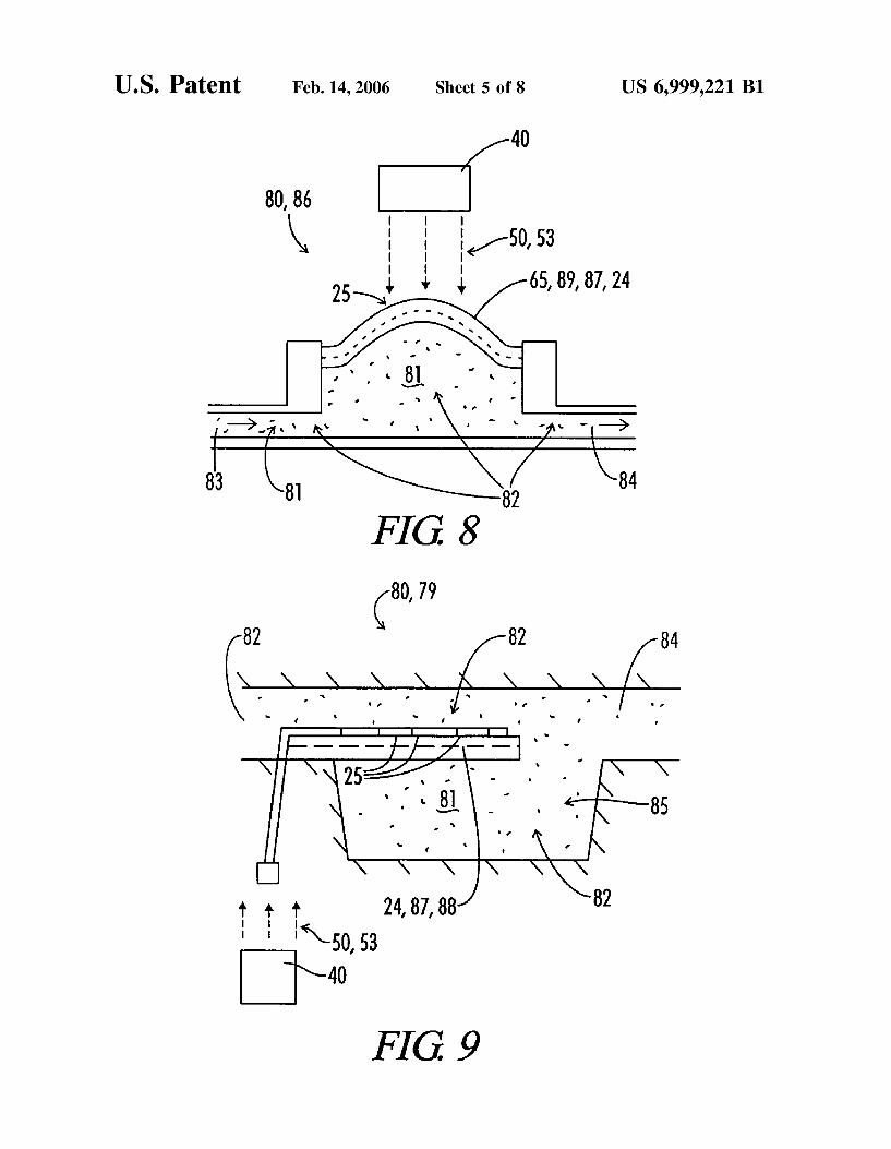
FIG. 8 is a schematic representation of a bimorphic polymeric photomechanical actuator in a fluidic diaphragm Pump.
FIG. 9 is a schematic representation of a bimorphic polymeric photomechanical actuator in a cantilevered beam- resonance chamber fluidic pump.
FIGS. 10a and 10b are schematic representations of bimorphic polymeric photomechanical actuator in a self- acting light beam focusingidefocusing apparatus.
FIGS. l la-l ld are schematic representations of bimor- phic polymeric photomechanical actuators in photonic switches.
DESCRIPTION OF THE PREFERRED EMBODIMENTS
The present invention is directed to an apparatus and method that converts light into mechanical work by illumi- nating a photosensitive portion of a flexible photomechani- cal body to produce mechanical deformation of the body. A photomechanical body comprises a photomechanical mate- rial, which is herein defined as a photosensitive material that exhibits a photomechanical effect when illuminated. A pho- tomechanical effect is herein defined as a bulk dimensional change in a photosensitive body induced by the influence of an applied field of light energy, such as a beam of light. Various embodiments of the present invention utilize this mechanical deformation of a photomechanical body to con- vert light energy into mechanical work. A description of a prototypical embodiment of the present invention illustrates the several mechanisms by which light interacts with pho- tosensitive materials to produce a photomechanical effect within a photosensitive material.
FIG. 1 shows one embodiment of the apparatus 10 of the present invention. Aphotomechanical body 20 comprising a photomechanical polymeric material 30 is shown affixed to a base 75. The photomechanical body 20 has a normal state surface 21 defining its normal bulk dimensions without an applied field of light illuminating the photomechanical body 20. A light source 40 is shown generating a light output 50. In this embodiment, the light output 50 is adapted to emit light in the visible or infra-red light spectrum. The emissions can be discrete frequencies emissions, broadband emissions or continuous emissions. The emissions can be combined to produce numerous variations. Light output 50 is shaped as necessary to illuminate a desired portion of normal state surface 21. That portion of normal state surface 21 is termed the illumination surface 25. The illumination surface 25 comprises a photomechanical polymeric material 30. The photomechanical polymeric material 30 of the photome- chanical body 20 is subjected to an applied field of selected
4 light energy 51 by the illuminating light output 50 and undergoes a photomechanical effect that causes deformation of its normal state surface 21 and its normal bulk dimen- sions. Such change in bulk dimension is shown in FIG. 2 by
5 the actuated state surface 22 of the photomechanical body 20. Upon removal of the illuminating light output 50, the photomechanical body 20 rapidly returns to its original normal state surface 21 and its normal bulk dimensions. In the embodiment shown in FIG. 2, the deformation is essen-
lo tially elastic. FIG. 2 further shows the path 95 swept out by the end of the photomechanical body 20 distal to the base 75 as the photomechanical body 20 deforms between its normal state surface 21 and its actuated state surface 22. One skilled in the art will recognize that the elastically deforming photomechanical body 20 can be used as an actuating mechanism for transforming light energy into another energy form by positioning a receiving structure so that the photomechanical body 20 contacts a movable receiving structure as the photomechanical body 20 undergoes defor-
2o mation. One skilled in the art will recognize that the elas- tically deforming photomechanical body 20 can also be used as an actuating element for positioning a contact in switch- ing mechanisms such as optical switches or electro-optical switches.
For the embodiment of the current invention shown in FIG. 1, the dominant mechanism by which light produces a photomechanical effect is the photothermal mechanism. As stated above, the polymeric photomechanical material 30
3o comprises a polymeric photosensitive material 31. Light energy is absorbed by the polymeric photosensitive material 31 and converted to heat. The material’s temperature increases, which, through thermal expansion of the bulk material, results in mechanical deformation. Typical char-
35 acteristic time of the photothermal mechanism is of the order of milliseconds and the magnitude of the effect is large. Strain (relative bulk dimensional deformation) due to the photothermal mechanism can be 1.0% and higher. In one embodiment of the invention, the required illumination
4o intensity of the photothermal mechanism is of the order of 0.01 W/cm2.
One secondary mechanism by which light produces a photomechanical effect in this embodiment of the present invention is photostriction. The photostriction mechanism is
45 a combination of photoelectric and converse piezoelectric mechanisms. Light generates an electric field in the photo- electric material through photoconductance, photovoltaic, pyroelectric effects, or a combination thereof. The electric field produces mechanical deformation due to piezoelectric-
so ity. Typical characteristic time of the photostriction mecha- nism is greater or equal to few milliseconds and the mag- nitude of the effect of photostriction does not exceed 0.5% strain. In one embodiment of the invention, the required illumination intensity of the photostriction mechanism is of
55 the order of 4 ~ 1 0 - ~ W/cm2. However, the contribution of the photostriction mechanism to the photomechanical effect may be significantly limited by heating effects of the illu- minating light.
An additional secondary mechanism by which light pro- 60 duces a photomechanical effect in this embodiment is elec-
trostriction. Light generates an optical field gradient on the interface boundary between two dielectric media. This causes the deformation of the boundary and contributes to mechanical deformation of the photomechanical body 20.
65 Typical characteristic time of the electrostriction mechanism is of the order of seconds and the magnitude of the effect of electrostriction is of the order of 0.01% strain. In
25

US 6,999,221 B1 5 6
one embodiment of the invention, the required illumination material 64. The gradient of the value of the thermal intfnsity of the electrostriction mechanism is of the order coefficients of linear expansion between the major opposing IO W/cm2. surfaces 62,69 may be linear or non-linear, depending on the
A tertiary mechanism by which light produces a photo- specific photomechanical polymeric material and the treat- mechanical effect in this embodiment is molecular reorien- s ment thereof. In other embodiments of the present invention, tation. Molecular reorientation is a mechanism that, under the gradient of the parametric value varies in multiple the right conditions, contributes to the photomechanical dimensions. In yet other embodiments of the present inven- effect. If the illuminating light is polarized and illuminates tion, the intrinsic photosensitive property of the polymeric a photosensitive molecule, the long axis of the photosensi- photomechanical material 30 having a non-isotropic para- tive molecule will align along the direction of the optic field. i o metric value that varies as a gradient within the photome- If these photosensitive molecules are embedded in a poly- chanical body 20 is a non-thermal intrinsic photosensitive mer, the molecule-polymer interaction will stress the poly- property, such as photoconductance. In still other embodi- mer and result in deformation. The molecular reorientation ments, individual gradients of parametric values of multiple meybanism can be fast (characteristic time of the order of intrinsic properties combine to form a complex gradient of 10 0.001% strain) or it can be very slow (characteristic time of FIG. 1 further shows a first plate layer of polymeric the order of 0.5 hour) with pronounced mechanical defor- photomechanical material 63 defined by the first major mation (up to 50% strain). In the present invention, the opposing surface 62 and the plane bisecting the thickness effects of the molecular reorientation mechanism are small. dimension of the plate 60. Asecond plate layer of polymeric
In one preferred embodiment of the present invention, the 20 photomechanical material 64 is similarly defined by that polymeric photomechanical material 30 comprises a photo- plane and the second major opposing surface 69. In the sensitive polyvinylidene fluoride 34 (PVDF). In that embodiment of the present invention shown in FIG. 1, the embodiment, all of the above-identified mechanisms com- average thermal coefficients of linear expansion in the first bine to produce a photomechanical effect when the PVDF 34 plate layer of polymeric photomechanical material 63 is is illuminated with light. However, in PVDF 34 the photo- zs greater than the average thermal coefficients of linear expan- thermal mechanism is the dominate mechanism. Other poly- sion in the second plate layer of polymeric photomechanical meric photomechanical materials 30 may be selected such material 64. FIG. 2 shows a light source 40 irradiating a that the photomechanical effect is produced by a combina- surface of the photomechanical body 20 of the embodiment tion of the above-identified mechanisms or a subset thereof. of the inventions shown in FIG. 1. FIG. 2 shows the bulk In one such embodiment shown in FIG. 6, the polymeric 30 deformation caused by a photomechanical effect. The pho- photomechanical material 30 comprises a photosensitive tothermal mechanism is the dominant mechanism causing mylar 36. The photosensitive mylar 36 undergoes a compa- the photomechanical effect in the embodiment of the inven- rable photomechanical effect when the mylar 36 is illumi- tion shown in FIG. 2. The light energy is absorbed by the nated with light. It is thought that the dominate mechanism polymeric photomechanical material 30 and is converted to of the photomechanical effect in polymeric photomechanical 3s heat, causing the material’s temperature to increase. The materials 30 would remain the photothermal mechanism, plate 60 of polymeric photomechanical material 30 is suf- although the relative contributions amongst the various ficiently thin that the temperature differential across the mechanisms may differ. plate’s thickness dimension is negligible. Linear expansion
In the preferred embodiment of the present invention occurs along the length, width and thickness of the plate 60 shown in FIG. 6, the structure of the photomechanical body 40 and causes mechanical deformation of the photomechanical 20 comprises a film or thin sheet 65 of polymeric photome- body. However, in relative terms, the length of the plate 60 chanical materials 30. In alternative embodiments of the is significantly larger than either the width or thickness of present invention, the structure of the photomechanical body the plate. 20 comprises a fiber, strand, rod or other elongated structure Referring to FIG. 2, plate 60 comprises an elongated plate of polymeric photomechanical materials 30. 4s 61, wherein its length is substantially greater than its width
In the photomechanical body 20 shown in FIG. 1, the or thickness such that the photomechanical deformations are polymeric photomechanical material 30 comprises a non- most pronounced along the longest axis of the strip. The first isotropic polymeric photomechanical material 32 that has at plate layer of polymeric photomechanical material 63 will least one non-isotropic, intrinsic photosensitive characteris- expand more than the second plate layer of polymeric tic in that the polymeric material has at least one intrinsic SO photomechanical material 64, since the temperature increase photosensitive property having a parametric value that var- is the same for both layers and the first has a greater thermal ies as regards at least one dimension of the structure of the coefficient of linear expansion. Since the plate layers are photomechanical body 20. By proper selection of the spe- affixed to each other, the unequal expansion causes the cific polymeric photomechanical material 30 and treatment elongated plate 61 to bend as it deforms from the bulk thereof, the photomechanical effect caused by illuminating ss dimensions of the normal state surface 21 to the bulk such a photomechanical body 20 can provide mechanically dimensions of the actuated state surface 22. FIG. 2 shows a advantageous results. In the embodiment of the present proximal end of the elongated plate 61 affixed to a base 75. invention shown in FIG. 1, the photomechanical body 20 In this configuration, light source 40 irradiates the illumi- comprises a plate 60 of polymeric photomechanical material nation surface 25 causing a photomechanical effect and 30 that has been selected and treated such that there is a 60 producing large deflections of the distal end of the elongated gradient across the thickness of the plate 60 as regards the plate 61 in a manner similar to that of a bimetallic thermostat thermal coefficient of linear expansion of the polymeric strips. photomechanical material 30. In this embodiment, the plate Herein, a photomechanical body 20 having regions or 60 comprises a first major opposing surface 62 and a second layers of polymeric photomechanical material 30 selected or major opposing surface 69. The plate 60 further comprises 65 treated such that the photomechanical body 20 comprises a a first plate layer of polymeric photomechanical material 63 non-isotropic polymeric photomechanical material 32 is and a second plate layer of polymeric photomechanical defined, as bimorphic photomechanical body 24. In the
seconds) with little mechanical deformation (less than is combined parametric values.

US 6,999,221 B1 7 8
embodiment shown in FIG. 2, the bimorphic photomechani- and mechanical work. In one embodiment, the actuating cal body 24 comprises a bimorphic photomechanical plate light is transmitted over conventional optic fibers and 26 comprising two layers of polymeric photomechanical through a lens assembly. In this embodiment, a low power material 30. In alternate embodiments of invention, the light source of less than 300 mW is used to generate bimorphic photomechanical plate 26 comprises multiple s mechanical displacement of the order of up to 10 mm. The layers of polymeric photomechanical material 30. In addi- light source is a visible light source which uses visible and tional alternate embodiments of invention, the bimorphic near-infrared (400 nm to 1550 nm) light which can be photomechanical plate 26 comprises a single layer of non- transmitted through optic fibers. A pulsed light generator isotropic polymeric photomechanical material 32. Similarly, may be utilized for conversion of continuous light into a in various alternate embodiments of the invention, the i o series of light pulses that are delayed with respect to each bimorphic photomechanical body 24 selectively comprises a other. Light delivery may then be performed in the present bimorphic photomechanical film, a thin bimorphic photo- invention by use of single or multiple mode conventional mechanical sheet, a bimorphic photomechanical fiber, and a optic fibers. Beam shaping optics are used to shape the light bimorphic photomechanical wound strand. This invention beams to illuminate the polymer body. One embodiment of contemplates numerous other structures of bimorphic pho- is the present invention uses a polymer body made of a tomechanical bodies. gold-coated 50-pm-thick film of polymer PVDF which
As stated above, a bimorphic photomechanical body 24 bends along the direction of the beam of visible light sent to may be formed by either proper selection and affixing of the film. This contrasts with the prior art’s use of a bimorph polymeric photomechanical materials 30 to form a non- based on photosensitive PLZT ceramics, which gains strain isotropic polymeric photomechanical material 32, or by 20 due to photovoltaic effect in combination with converse treatment of a polymeric photomechanical material 30 to piezoelectric effect. The prior art bimorph bends when its form a non-isotropic polymeric photomechanical material PLZT part elongates after illumination with UV light. 32. For example, a bimorphic photomechanical body 24 may The body of the photo-driven actuator is made of photo- be formed as a result of fabrication process of a number of sensitive piezoelectric polymer such as polyvyniledene fluo- polymer films such as mylar and PVDF. These polymers zs ride known as PVDF. PVDF is a well known piezoelectric after being processed into thin films are usually rolled and polymer but its behavior as a photosensitive material may be stored into rolls. This creates an effect of “memory” in the utilized for changing its shape in response to visible light. film. After being cut into plane sheets, the film still “remem- Referring now to FIG. 3, photomechanical apparatus 10 bers” its initial shape in a roll. This is due to the initial of this invention comprises a photomechanical actuator 70. packing of the polymer molecules trying to adjust for the 30 The photomechanical actuator 70 shown in FIG. 3 com- shape of the film in a roll. The outer half of the film, which prises a bimorphic photomechanical body 20 having an is more distal to the center of the roll, will have a greater illumination surface 25. An actuator output element 71 is thermal coefficient of linear expansion while the inner part shown affixed to the bimorphic photomechanical body 20. In tends to expand less. Thus, the process of light induced this embodiment the actuator output element 71 comprises heating returns the film to its cylindrical shape. Even bend- 3s an actuator output arm 72, although other structures could be ing the film in the opposite direction (with respect to its substituted as an actuator output element 71. The bimorphic original curvature in a roll) and storing it bent for a year does photomechanical body 20 is shown in both its normal state, not change the film’s tendency to return to its original shown as normal state surface 21, and its actuated state, curvature upon the illumination. shown as actuated state surface 22. A light source 40
Bimorphic photomechanical properties can be induced in 40 generates a light output 50, which is used to illuminate polymeric photosensitive materials by a number of tech- illumination surface 25. The bimorphic photomechanical niques. One method is exposure of a photosensitive poly- body 20 deforms from the its normal state surface 21 to its meric film or fiber to UV radiation. In polymers which have actuated state surface 22 in response to illumination of the strong absorption coefficients for UV light, such as polyim- illumination surface. Such deformation moves the actuator ide, this can create a modification of molecules preferably on 4s output element 71 along path 95 to the actuator receiving the UV exposed side. The modification will make the element 73. The actuator receiving element 73 is adapted to exposed polymer less expandable due to light-induced heat- receive the actuator output element 71 and be movably ing than that on the opposite side. Other methods of surface displaced by the actuator output element 71 along path 96, treatment of polymeric photosensitive materials that simi- thus converting the kinetic energy of the bimorphic photo- larly modify polymer molecular structure can be suggested SO mechanical body 20 into another form of energy. In this for making a bimorph: ion or electron beam modification, embodiment, the other form of energy is the kinetic energy differential drying, chemical processing by a gas or liquid, of rotation of the actuator receiving element 73. etc. An alternative method of forming a bimorphic photo- In this embodiment of the present invention, the light mechanical body 24 is to coat one side of a photosensitive source 40 comprises a light generation device 41 and a light polymeric film with an adhesive layer that has a substan- ss transfer device 44. The light generation device 41 is adapted tially different thermal coefficient of linear expansion or a to generate a pulsed light output 53. In this embodiment, substantially different parametric value of another intrinsic photosensitive property. Similarly, yet another method of forming a bimorphic photomechanical body 24 is to adhere one photosensitive polymeric film to another photosensitive 60 polymeric film that has a substantially different thermal coefficient of linear expansion or a substantially different parametric value of another intrinsic photosensitive prop- erty.
The present invention is directed to providing a simple, 65 compact, and inexpensive means of converting low power
light generation device 41 comprises a laser 42 for gener- ating a light output 50 in the spectrum between 300 nm and 10000 nm. In another embodiment, light generation device 41 comprises a laser 42 for generating a light output 50 in the spectrum between 400 nm and 3000 nm. Referring again to the embodiment in FIG. 3, the light generation device 41 further comprises a pulsed light generator 48 for converting the light output 50 to a pulsed light output 53. In this embodiment, the laser 42 is an Ar-ion laser 43 operating at 488 nm. However, many other types of lasers are suitable for
visible or mid-infrared radiation into mechanical movement use in this invention, depending on the particular polymeric

US 6,999,221 B1 9
photomechanical material 30 selected for use in the bimor- phic photomechanical body 24. Examples of lasers used in typical variations of this and similar embodiments for gen- erating a light output 50 in the spectrum between 300 nm and 10000 nm include: He-Ne lasers; Nd: YAG lasers; Ti: sapphire lasers; tunable solid state and dye lasers; semicon- ductor lasers; and carbon dioxide lasers. The He-Ne laser operates at 632.8 nm. The Nd: YAG laser operates at 1064 nm and at the second harmonic of 532 nm. The Ti: sapphire lasers are tunable between 750 nm and 950 nm, while solid state and dye lasers are tunable between 400 nm and 3000 nm. Semiconductor lasers are selectable for operation at specific wavelengths from 400 nm to 3000 nm. However, the most suitable semiconductor lasers for commercial fiber optic systems are those which operate at 800 nm, 1300 nm, or 1550 nm. Semiconductor lasers; operating at 1300 nm or 1550 nm are particularly adaptable for use in long distance fiber optic communication. Carbon dioxide (CO,) laser operating at approximately 10000 nm produces radiation that is strongly absorbed by pure polymer PVDF. However, only limited types of optical fibers are designed to transmit Carbon dioxide (CO,) laser radiation, and then only for relatively short distances of less than 10 ft.
Referring again to FIG. 3, the light transfer device 44 of the embodiment shown comprises a fiber optic cable 45 designed to direct the pulsed light output 53 from the light generation device 41 to the illumination surface 25 of the bimorphic photomechanical body 20. In this embodiment, the light output 50 can be in the visible or infrared spectrum between 400 and 1550 nm. Operating in the visible or infrared spectrum between 400 and 1550 nm makes it practical to deliver the pulsed light output 53 to the photo- mechanical body 20 via conventional optical fibers without the significant loss of light energy of the prior art. In the preferred embodiment of the present invention, the pulsed light output 53 is transferred via a multi-mode fiber optic cable 45 to an optical system 47 designed to direct the pulsed light output 53 upon the illumination surface 25 of the bimorphic photomechanical body 20.
Since the bimorphic photomechanical body 20 is com- prised of a polymeric material, it has significant advantages over the PLZT ceramics of the prior art. Among the advan- tages of polymeric photomechanical materials 30 is greater mechanical flexibility and significantly greater maximum strain in elastic deformation. Furthermore, the efficiency of conversion of the energy of light into mechanical work is higher than that of the materials of the prior art. In the embodiment shown in FIG. 3, the preferred bimorphic photomechanical body 20 comprises a photosensitive poly- vinylidene fluoride (PVDF) 34. One preferred photosensi- tive polyvinylidene fluoride (PVDF) 34 is made from a gold coated 50-pm-thick PVDF layer forming a bimorphic poly- vinylidene fluoride film 38, which is specifically adapted for reciprocally and reversibly changing its shape after being illuminated with one or multiple light beams. This provides a spring like effect. The light exposure bends the film in a first direction and then after exposure is removed, the film returns to its original position, providing a quick reciprocal movement. In one embodiment, upon the illumination with a 15-mW He-Ne laser, a PVDF film with dimensions of 5x40 mm produced a maximum static force of approxi- mately ~ . O X ~ O - ~ N. The force is enough to accelerate a 1-g object from rest to a speed of 10 cmis in one second. The maximum travel distance of the free end of the bimorphic film was 5 mm over a period of time of 1 s . The bending is shown in FIG. 3 with the movement illustrated by path 95.
10 The functional operation of the reciprocating photome-
chanical actuator 70 may be further understood with refer- ence to FIG. 3 where the continuous light output 50 from the light source 40 is converted by the pulsed light generator 48
s to a pulsed light output 53 having certain characteristics with respect to the pulse, including pulse amplitude, pulse dura- tion and pulse repetition rate. The pulsed light output 53 is coupled with fiber optic cable 45 and transmitted towards the bimorphic photomechanical body 24. The pulsed light
i o output 53 is decoupled from the fiber optic cable 45, shaped by an optical system 47. The optical system 47 directs the beam to the illumination surface 25 on the bimorphic photomechanical body 24. The bimorphic photomechanical body 24 bends and changes its shape in response to the
is illumination of each pulse of the pulsed light output 53. This deformation moves the actuator output element 71 along path 95 to the actuator receiving element 73 producing mechanical motion of the actuator receiving element 73 along path 96. The bimorphic photomechanical body 24 will
20 return to its original shape after each light pulse has been removed and reset for the next pulse.
Referring now to FIG. 4, an embodiment of a reciprocat- ing photomechanical actuator 70 is shown having a two range bimorphic photomechanical assembly 12. The two
zs range photomechanical actuator 70 includes a laser 42 for providing a coherent beam 52. Apreferred embodiment uses an Ar-ion laser 43 operating at 488 nm. The Ar-ion laser 43 generates a coherent beam 52 with sufficient strength to be split into a first light output 54 and a second light output 55
30 by the multi-mode optic fiber splitter 46 in to the arms of the splitter 46. Each arm then goes into separate optic systems 47 through the separate pulsed light generators 48 and into separate fiber optic cables 45. The first light output 54 is directed toward the illumination surface 25.
Complex actuating motions are possible using bimorphic photomechanical bodies in various configurations. For example, two ranges of motion for a bimorphic photome- chanical assembly 12 are shown in FIG. 4, with both ranges of motion moving the actuator output element 70. This
40 bimorphic photomechanical assembly 12 comprises two bimorphic photomechanical plates 26 affixed to each other in an orthogonal orientation and each having freedom of movement in the y-z plane. This produces a trajectory of motion of the actuator output element 71 in the y-z plane.
4s Note, that in this embodiment, the first light output 54 and the second light output 55 have the same pulse duration and pulse repetition rate. Where the light outputs 54, 55 have a generally sinusoidal pattern and the time delay between the sinusoidal patterns is close to the quarter of period, the
SO trajectory of motion of the actuator output element 71 will follow a generally elliptical path 97. The shape of the trajectory may be varied by changing the pulse duration, pulse amplitude, and the time delay between the pulses in each light output.
Referring now to FIG. 5, an embodiment of a reciprocat- ing photomechanical actuator 70 is shown having a three range of motion bimorphic photomechanical assembly 12. This bimorphic photomechanical assembly 12 comprises three bimorphic photomechanical plates 26 affixed to each
60 other in an orthogonal orientation and each having freedom of movement in a plane. In alternate embodiments, a single bimorphic photomechanical plate 26 is constructed in a twisted manner to provide for the three ranges of control. FIG. 5 shows a first, second and third light output 54,55,56,
65 each light output directed toward an illumination surface 25 of a different bimorphic photomechanical body 24 of the bimorphic photomechanical assembly 12. This produces a
3s
ss

US 6,999,221 B1 11 12
trajectory of motion of the actuator output element 71 in the is illuminated. Referring now to FIG. l lb, the photome- x-y-z space. Note, that in this embodiment, first, second and chanical body 24 of the photonic switch 100 is not illumi- third light outputs 54, 55, 56, may have different pulse nated and is in a normal, non-deformed state. In a normal amplitude, pulse duration, pulse repetition rate, and time state, the photomechanical body 24 positions the reflector delay. This can produce a complex trajectory of motion of s 104 so as to not reflect the signal light beam 106 from the the actuator output element 71, shown as three dimensional fiber optic transmitter 103 to the fiber optic receiver 105 and compound path 98. The shape of the trajectory may be interrupts optical communication across the photonic switch varied by changing the pulse duration, pulse amplitude, and 100. Thus, in this embodiment, the photonic switch 100 is time delay for at least one of the first, second or third light configured so as to open when the photomechanical body 24 outputs 54, 55, 56.
Referring now to FIG. 6, the drawings shows a three Referring to FIGS. l l c and l ld, a photonic switch 100 dimensional range photokinetic apparatus 11 for positioning similar to the embodiment of FIGS. l l a and l l b is shown. an executing element, said apparatus 11 having actuator Referring now to FIG. l l c , the photomechanical body 24 of output arm 72 adapted to transfer the movement of the the photonic switch 100 is not illuminated and is in a normal, output point to the executing element. The actuator output is non-deformed state. In a normal state, the photomechanical arm 72 is affixed to a bimorphic photomechanical body 24. body 24 positions the reflector 104 so as to reflect the signal The bimorphic photomechanical body 24 comprises a thin light beam 106 from the fiber optic transmitter 103 to the sheet 65 of a photosensitive mylar 36 and has multiple fiber optic receiver 105 and provides optical communication illumination surfaces 25. In an alternate embodiment, the across the photonic switch 100. Thus, in this embodiment, bimorphic photomechanical body 24 comprises a bimorphic 20 the photonic switch 100 is configured so as to close when the polyvinylidene fluoride film 38. FIG. 6 shows a first and photomechanical body 24 is not illuminated. Referring to second light output 54,55, each light output directed toward FIG. l ld, the photomechanical body 24 of the photonic different illumination surface 25 of the bimorphic photome- switch 100 is illuminated and undergoes bimorphic defor- chanical body 24. This produces a trajectory of motion of the mation sufficient to position the reflector 104 so as to not actuator output element 71 in the x-y-z space. Note, that in zs reflect the signal light beam 106 from the fiber optic trans- this embodiment, the first and second light output 54, 55, mitter 103 to the fiber optic receiver 105 and interrupts may have different pulse amplitude, pulse duration, pulse optical communication across the photonic switch 100. repetition rate, and time delay between pulses in each Thus, in this embodiment, the photonic switch 100 is output. This can produce rather a complex trajectory of configured so as to open when the photomechanical body 24 motion of the actuator output element 71, shown as three 30 is illuminated. dimensional compound path 98. The shape of the trajectory In preferred embodiments of FIG. lla-lld, the photome- may be varied by changing the pulse duration, pulse ampli- chanical polymeric material 30 is non-isotropic. Further, the tude, and time delay of pulses for at least one of first or light source 40 comprises a fiber optic illuminator similar to second light output 54, 55. One of the possible applications transmitter 103 and powered by laser 42, and more particu- of this embodiment could be in non-piezoelectric drives for 3s larly by an infrared laser 43 of a communication wavelength cantilevers of a scanning probe microscope (SPM). 1300 or 1550 nm. One skilled in the art will recognize that
Referring to FIGS. l l a and l lb, a photonic switch 100 is may other configurations of the is photonic switch readily shown as one embodiment of the present invention. The present themselves. For example, in one embodiment of the photomechanical photonic switch 100 includes a bimorphic present invention, the fiber optic transmitter 103 and the photomechanical body 24 having an illumination surface 25. 40 fiber optic receiver 105 are positioned in a linear configu- The bimorphic photomechanical body 24 is formed from a ration such that the fiber optic transmitter 103 directly photomechanical polymeric material 30 and affixed to a base illuminates the fiber optic receiver 105 with the signal light 75.Alight source 40 is adapted to selectively generate a light beam 106. The photomechanical body 24 is be positioned output 50 to illuminate the illumination surface 25. The such that it can be alternately configured 20 either to block photonic switch 101 is disposed in a fiber optic circuit 102 4s the signal light beam 106 and interrupt optical communica- and includes a fiber optic transmitter 103, a reflector 104 tion or to allow the signal light beam 106 to pass and allow affixed to said bimorphic photomechanical body 24, and at optical communication. Such alternate configuration of the least one fiber optic receiver 105. The fiber optic transmitter photomechanical body 24 is determined by the illumination 103 is adapted to generate a signal light beam 106. When the or non-illumination of the photomechanical body 24. Other photonic switch 100 is in the closed configuration, the SO embodiments of the photonic switch 100 of the present reflector 104 is positioned to reflect the signal light beam invention incorporate multiple the fiber optic transmitters 106 from the fiber optic transmitter 103 to the fiber optic 103 and the fiber optic receivers 105. receiver 105 and provides optical communication across the Referring to FIGS. 7a and 7b, a photomechanical elec- photonic switch 100. When the photonic switch 100 is tronic switch 90 is shown as one embodiment of the present configured in the open configuration, the reflector 104 is not ss invention. The photomechanical electronic switch 90 positioned to reflect the signal light beam 106 from the fiber includes a bimorphic photomechanical body 24 having an optic transmitter 103 to the fiber optic receiver 105 and, thus, illumination surface 25. The bimorphic photomechanical interrupts optical communication across the photonic switch body 24 is formed from a photomechanical polymeric 100. material 30 and affixed to a base 75. A light source 40
Referring to FIG. l la , the photomechanical body 24 of 60 generates a light output 50 to illuminate the illumination the photonic switch 100 is illuminated and undergoes bimor- surface 25. An electronic switch 91 includes a switch contact phic deformation sufficient to position the reflector 104 so as 93 affixed to the bimorphic photomechanical body 24 and at to reflect the signal light beam 106 from the fiber optic least one circuit contact 94 disposed in an electrical circuit transmitter 103 to the fiber optic receiver 105 and provides 92. Referring to FIG. 7a, this embodiment of the photome- optical communication across the photonic switch 100. 65 chanical electronic switch 90 is configured to position the Thus, in this embodiment, the photonic switch 100 is switch contact 93 so as to close the electronic switch 91 configured so as to close when the photomechanical body 24 when the photomechanical body 24 is illuminated (shown in
i o is not illuminated.

US 6,999,221 B1 13 14
solid lines) and to position the switch contact 93 so as to frequency of the pulsed light output 53 is tuned to the proper open the electronic switch 91 when the photomechanical frequency, the bimorphic photomechanical cantilevered body 24 is not illuminated (shown in broken lines). Refer- beam 88 reciprocally deforms in a vibration tuned to a ring to FIG. 7b, this embodiment of the photomechanical harmonic of the resonance chamber 85. These harmonic electronic switch 90 is configured to position the switch s oscillations produce pressure waves within the fluidic pump contact 93 so as to open the electronic switch 91 when the chamber 82 sufficient to draw fluid 81 from the fluid inlet photomechanical body 24 is illuminated (shown in solid port into the fluidic pump chamber 82 and then to force fluid lines) and to position the switch contact 93 so as to close the 81 from the fluidic pump chamber 82 into the fluid outlet electronic switch 91 when the photomechanical body 24 is port 84. not illuminated (shown in broken lines). In a preferred i o In alternate embodiments of the photomechanical fluidic embodiment, the light source 40 comprises a laser 42, and pumps 80 shown in FIGS. 8 and 9, the light source 40 more particularly an Ar-ion laser 43. comprises a laser 41, specifically an Ar-ion laser adapted to
The photomechanical actuators 70 of this invention are generate said pulsed light output 53. A fiber optic cable 45 light driven and do not require electrical power or electrical is adapted to direct the light output 50 from a light genera- contacts. It would be highly desirable to integrate the is tion device 41 to said illumination surface 25 of the bimor- photomechanical actuators 70 of this invention, especially as phic photomechanical body 24. An optical system 47 photomechanical fluidic pumps 80, into micro-electro-me- focuses the light output 50. In variations of these embodi- chanical or micro-electro-opto-mechanical systems ments, the bimorphic photomechanical bodies 24 have a (MEMSNEOMS) such as MEMS fuel cells. Two embodi- plurality of illumination surfaces 25, and the light transfer ments of the photomechanical actuators 70 are disclosed as 20 devices 44 further comprising optic fiber splitters 46 adapted photomechanical fluidic pumps 80. Referring now to FIG. 8, to split light output 50 so as to selectively illuminate the a photomechanical fluidic pump 80 is shown comprising a individual illumination surfaces 25. Tunable lasers 41 can be fluidic diaphragm pump 86. The fluidic diaphragm pump 86 used to vary the pulse repetition pattern, pulse duration, and comprises a fluidic pump chamber 82, an inlet port 83, and pulse amplitude so as to control the deformation shape and a fluid outlet port 84. Abimorphic photomechanical body 24 zs deformation frequency of either the bimorphic photome- is shown comprising a fluidic actuator 87 for providing chanical cantilevered beam 88 or the bimorphic photome- actuating motion to pump the fluid 81 from the fluidic pump chanical sheet 89, depending on the type of fluidic pump 80. chamber 82 through the fluid outlet port 84. A bimorphic Where the fluid 81 does not significantly absorb or scatter photomechanical sheet 89 comprising a photomechanical the light output 50, a coherent beam 52 of pulsed light output polymeric material 30 is disposed adjacent to the fluidic 30 53 may be transmitted through the fluid 81 to the bimorphic pump chamber 82 and comprises the bimorphic photome- photomechanical cantilevered beam 88 or the bimorphic chanical body 24. A light source 40 is shown generating a photomechanical sheet 89. Otherwise, fiber optic cable can pulsed light output 53 to illuminate an illumination surface be laid atop the bimorphic photomechanical cantilevered 25. The bimorphic photomechanical sheet 89 is adapted to beam 88 (as shown in FIG. 9) or the bimorphic photome- move bimoruhicallv in resuonse to illumination of said 3s chanical sheet 89 so as to directlv illuminate the desired illumination surface by said light output, and is shown in an activated deformation, bending away from the fluid 81 in the fluidic pump chamber 82. This generates a lower pressure in the chamber and draws fluid 81 from the fluid inlet port 83 into the fluidic pump chamber 82. When the illumination of the illumination surface 25 is removed, the bimorphic pho- tomechanical sheet 89 returns to its original dimensions and exerts a compressive force against the fluid 81, thus, raising the pressure in the chamber and forcing the fluid through the fluid outlet port 84. In an alternate embodiment of the invention, the orientation of the bimorphic photomechanical sheet 89 is reversed such that the sheet bends downward into the fluid 81 when activated by the illumination of the illumination surface 25.
Referring now to FIG. 9, a photomechanical fluidic pump 80 is shown comprising a fluidic resonance pump 79. The fluidic resonance pump 79 comprises a fluidic pump cham- ber 82, an inlet port 83, and a fluid outlet port 84. A bimorphic photomechanical body 24 is shown comprising a fluidic actuator 87 for providing actuating motion to pump the fluid 81 from the fluidic pump chamber 82 through the fluid outlet port 84. A bimorphic photomechanical cantile- vered beam 88 comprising a photomechanical polymeric material 30 is disposed above a resonance chamber 85 within the fluidic pump chamber 82 and comprises the bimorphic photomechanical body 24. A light source 40 is shown generating a pulsed light output 53 to illuminate at least one illumination surface 25 along the bimorphic pho- tomechanical cantilevered beam 88. The bimorphic photo- mechanical cantilevered beam 88 is adapted to move bimor- phically in response to illumination of the illumination surfaces 25 by the pulsed light output 53. As the repetition
illumination surfaces 25. Referring to FIGS. 10a and lob, an embodiment of the
present invention comprising a light beam focusing appa- ratus 110 is shown. In these embodiments the light beam
40 focusing apparatus 110 is a self-actuating light beam focus- ing apparatus 110. The apparatus is self-actuating in that the light beam being focused or defocused by the apparatus causes the apparatus to deform and change the focal quali- ties of the apparatus. The light beam has a divergence
4s parameter which is a measure of the change in the cross- sectional area of the light beam as it travels along a beam path. Where the light beam’s cross-sectional area is reduced as it travels along its beam path, the divergence parameter is negative and the beam is said to be focused toward a focal
SO point. Where the light beam’s cross-sectional area is increased as it travels along its beam path, the divergence parameter is positive and the beam is said to be defocused from an apparent focal point.
The self-actuating light beam focusing apparatus 110 ss includes a bimorphic photomechanical body 24 having an
illumination surface 25. The bimorphic photomechanical body 24 is formed from a photomechanical polymeric material 30. The light output 50 is shaped by the optic system 47. The illumination surface 25 in this embodiment
60 is flat (planar) while in the normal state and has a mirrored surface that reflects a large portion of any illuminating light. Alight source 40 generates a light output 50 to illuminate the illumination surface 25 and causes the photomechanical body 24 to bimorphically deform itself into a mirrored lens.
65 Referring to FIG. loa, this embodiment of the self- actuating light beam focusing apparatus 110 is adapted to focus the light beam output 50 when the photomechanical

US 6,999,221 B1 15
body 24 is illuminated. The illumination surface 25 bimor- phically deforms to form a concave, reflective surface rela- tive to the illuminating light beam output 50. The resulting concave mirror tends to shift the divergence parameter of the illuminating light beam output 50 in a negative direction by an amount corresponding to the shape of the mirror. In the embodiment as shown in FIG. loa, the cross-sectional area of the reflected light beam (shown in broken lines) is reduced as the reflected light beam is focused toward a focal point. Referring to FIG. lob, this embodiment of the self- acting light beam focusingidefocusing apparatus 110 is configured to defocus (or difuse) the light beam output 50 when the photomechanical body 24 is illuminated. The illumination surface 25 bimorphically deforms to form a convex reflective surface relative to the illuminating light beam output 50. The resulting convex mirror tends to shift the divergence parameter of the illuminating light beam output 50 in a positive direction by an amount corresponding to the shape of the mirror. In the embodiment as shown in FIG. lob, the cross-sectional area of the reflected light beam (shown in broken lines) is increased as the beam diverges away from an apparent focal point. In a preferred embodi- ment, the light source 40 comprises a laser 42, and more particularly an Ar-ion laser 43. The applications of this embodiment of the invention include long distance open air light transmission lines (focusing) and protection of sensi- tive photodetectors against intensive laser radiation (defo- cusing).
Other similar embodiments of the light beam focusing apparatus 110 of this invention include embodiments where the photomechanical body 24 and its illumination surface 25 is either convex or concave in the normal, non-illuminated state. Still other embodiments are not self-actuating and include two or more light beams. In these embodiments, a light beam output 50 used to activate and shape the bimor- phic deformation of the illumination surface 25. The deformed illumination surface 25 is then used to focus or defocus a second light beam. The second light beam would be of a frequency not causing a photomechanical effect in the photomechanical material selected to comprise the illu- mination surface 25. The photomechanical body of yet additional embodiments would transmit rather than reflect a large portion of the light beam output 50. In such embodi- ments, the convex illumination surfaces 25 would tend to focus the light beam output 50 while the concave illumina- tion surfaces 25 would tend to defocus the light beam output 50.
Further advantages of the present invention include: (a) The photomechanical actuator 70 generates greater
mechanical displacement with greater energy conver- sion efficiency than the prior art actuators;
(b) Activating light in the visible and infrared spectrum can be delivered to the bimorphic photomechanical body 24 through conventional communication optic fibers without significant power losses;
(c) The polymeric photomechanical material 30 can be easily processed and shaped using a variety of tech- niques such as molding, stamping, bending, and cut- ting;
(d) The polymeric photomechanical material 30 is suit- able for thin film technologies such as spin casting, spraying, dipping, vapor deposition, contact printing, and photolithography, thus making it possible to inte- grate the photomechanical actuator 70 into micro- electro-mechanical or micro-electro-opto-mechanical systems (MEMSNEOMS);
S
10
1s
20
2s
30
3s
40
4s
so
5s
60
65
16 (e) The photomechanical fluidic pumps 80 of this inven-
tion are light driven and do not require electrical power or electrical contacts, thus making it advantageous to integrate the photomechanical fluidic pumps 80 into micro-electro-mechanical or micro-electro-opto-me- chanical systems (MEMSNEOMS) such as MEMS fuel cells;
( f ) A variety of trajectories of mechanical motion of the photomechanical actuator 70 can be achieved without changing an embodiment by simply changing the char- acteristics of the pulsed light output 53, such as pulse intensity, duration, repetition pattern, time delay between pulses, or by refocusing the pulsed light output 53 on different illumination surfaces 25 of the bimor- phic photomechanical body 24;
(g) Photomechanical bodies are comprised of impact and stress resistant polymeric photomechanical materials 30; and
(h) The photonic switch 100 of this invention is driven by the same optical signal as those being switched and does not require conversion into electric signal at any stage, thus making it advantageous to integrate the photonic switch 100 into photonic communication cir- cuits with the highest up-today data flow rates.
Uses of the present invention include: light-driven micro- electro-mechanical systems (MEMS) and micro-electro- opto-mechanical systems (MEOMS); smart materials or skins; and photonic switches based on photo-driven deflec- tors.
Thus, although there have been described particular embodiments of the present invention of a new and useful “Bimorphic Polymeric Photomechanical Actuator,” it is not intended that such references be construed as limitations upon the scope of this invention except as set forth in the following claims.
What is claimed is: 1. A bimorphic polymeric photomechanical body com-
a layer of non-isotropic polymeric photomechanical mate-
2. A photomechanical body comprising: a first layer of a first polymeric photomechanical material;
and a second layer of a second polymeric photomechanical
material, said second layer of a second polymeric photomechanical material affixed to said first layer of said first polymeric photomechanical material, each said polymeric photomechanical material adapted such that illumination of said polymeric photomechanical material by an applied field of selected light energy induces a photomechanical effect producing a bulk dimensional change,
wherein, illumination of said first polymeric photome- chanical material by an applied field of selected light energy causes a bimorphic deformation of said photo- mechanical body.
prising:
rial.
3. A photomechanical apparatus comprising: a photomechanical body, said photomechanical body
comprising a polymeric photomechanical material, said polymeric photomechanical material adapted such that illumination of said polymeric photomechanical mate- rial by an applied field of selected light energy induces a photomechanical effect producing a bulk dimensional change proportional to an intrinsic property of said polymeric photomechanical material, and
wherein, said intrinsic property varies along a gradient within said polymeric photomechanical material such

US 6,999,221 B1 17 18
that said bulk dimensional change comprises a bimor- wherein, illumination of said polymeric photomechanical phic deformation of said photomechanical body. body by said light source causes a bimorphic deforma-
4. The apparatus of claim 3, wherein said bulk dimen- tion of said photomechanical body. sional change is proportional to a parametric value of said 18. The apparatus of claim 17, wherein said polymeric intrinsic property. s photomechanical body comprises an illumination surface,
5. The apparatus of claim 4, wherein said parametric value said illumination surface comprising a polymeric photosen- is the thermal coefficient of linear expansion of the poly- sitive material, meric photomechanical material. wherein said light source is adapted to generate an illu-
6. The apparatus of claim 4, wherein said photomechani- minating field of selected light energy, and said light cal body comprises an elongated plate, said elongated plate i o source is disposed so as to selectably illuminate said comprising a first plate layer of a first polymeric photome- chanical material and a second plate layer of a second polymeric photomechanical material,
wherein, said first plate layer is affixed upon said second plate layer,
wherein, said first polymeric photomechanical material comprising said first plate layer has a first plate layer average parametric value of said intrinsic property along said gradient and said polymeric photomechani- cal material comarisinn said second alate laver has a
illumination surface, and wherein, said polymeric photosensitive material has an
intrinsic property, said intrinsic property having a para- metric value, said polymeric photosensitive material adapted such that illumination of said polymeric pho- tosensitive material by a field of selected light energy induces an elastic bulk dimensional change propor- tional to said parametric value, said parametric value varying along a gradient within said polymeric photo-
20 sensitive. material such that said bulk dimensional
is
L a
second plate layer average parametric value of said change comprises a bimorphic deformation of said intrinsic property along said gradient, and photomechanical body.
wherein, said first plate layer average parametric value is 19. The apparatus of claim 18, wherein said parametric greater than said second plate layer average parametric value is the thermal coefficient of linear expansion of said value. zs polymeric photosensitive material.
7. The apparatus of claim 3, wherein said applied field of 20. The apparatus of claim 18, wherein said applied field selected light energy comprises an applied spectrum of light of selected light energy comprises an applied spectrum of energy selected from the visible and infrared light spectrum. light energy selected from the visible and infrared light
8. The apparatus of claim 7, wherein said applied spec- spectrum. trum of light energy comprises a discrete spectrum of light 30 21. The apparatus of claim 20, wherein said applied energy selected from the visible and infrared light spectrum. spectrum of light energy comprises a discrete spectrum of
9. The apparatus of claim 7, wherein said applied spec- light energy selected from the visible and infrared light trum of light energy comprises a continuous spectrum of spectrum. light energy selected from the visible and infrared light 22. The apparatus of claim 21, wherein said applied spectrum. 3s spectrum of light energy comprises a continuous spectrum
10. The apparatus of claim 3, wherein said applied field of of light energy selected from the visible and infrared light selected light energy comprises an applied spectrum of light spectrum. energy selected from the light spectrum between 300 nm and 23. The apparatus of claim 20, said applied field of 10000 nm. selected light energy comprises an applied spectrum of light
11. The apparatus of claim 3, wherein said photomechani- 40 energy selected from the light spectrum between 300 nm and cal polymeric material comprises a photosensitive polyvi- 10000 nm. nylidene fluoride. 24. The apparatus of claim 18, wherein said polymeric
12. The apparatus of claim 11, wherein said photosensi- photosensitive material comprises a photosensitive polyvi- tive polyvinylidene fluoride comprises a bimorphic polyvi- nylidene fluoride. nylidene fluoride film. 25. The apparatus of claim 24, wherein said photosensi-
13. The apparatus of claim 12, wherein said bimorphic tive polyvinylidene fluoride comprises a bimorphic polyvi- polyvinylidene fluoride film comprises a polyvinylidene nylidene fluoride film. fluoride film coated with a light absorbing material. 26. The apparatus of claim 24, wherein said bimorphic
14. The apparatus of claim 3, wherein said photomechani- polyvinylidene fluoride film comprises a polyvinylidene cal polymeric material comprises a photosensitive mylar.
15. The apparatus of claim 3, wherein said photomechani- 27. The apparatus of claim 18, wherein said photome- cal body comprises a structure formed from said polymeric chanical body comprises a structure formed from said poly- photomechanical material, said structure selected from the meric photosensitive material, said structure selected from group comprising an elongated plate, a thin sheet, a fiber, the group comprising an elongated plate, a thin sheet, a fiber, and a wound strand. ss and a wound strand.
16. The apparatus of claim 3, wherein said photomechani- 28. The apparatus of claim 18, wherein said photome- cal effect produces an elastic bulk dimensional change chanical body comprises an elongated plate, said elongated within said polymeric photomechanical material and plate comprising a first plate layer of polymeric photosen-
wherein, cyclic illumination of said polymeric photome- sitive material and a second plate layer of polymeric pho- chanical material by said applied field of selected light 60 tomechanical material, each said first and second plate layer energy causes reciprocating bimorphic deformation of having major opposing surfaces, said photomechanical body. wherein, one major surface of said first plate layer is
affixed upon one major surface of said second plate
wherein, said polymeric photosensitive material compris- ing said first plate layer has a first plate layer average parametric value of said intrinsic property along said
4s
SO fluoride film coated with a light absorbing material.
17. An photomechanical apparatus comprising: a base; layer, a polymeric photomechanical body, said polymeric pho- 65
a light source, and tomechanical body affixed to said base;

US 6,999,221 B1 19
gradient and said polymeric photosensitive material comprising said second plate layer has a second plate layer average parametric value of said intrinsic prop- erty along said gradient, and
wherein, said first plate layer average parametric value is greater than said second plate layer average parametric value.
29. The apparatus of claim 18, said light source further adapted to cyclically generate an illuminating field of selected light energy, and
wherein, said photomechanical body is adapted for recip- rocating, bimorphic deformation in response to said cyclic illumination of said illumination surface by said applied field of selected light energy.
30. Aphotomechanical actuator, said actuator comprising: a bimorphic photomechanical body having an illumina-
tion surface, said bimorphic photomechanical body comprising at least one photomechanical polymeric material, said bimorphic photomechanical body further comprising an actuator output element;
a light source adapted to generate a light output, said light source disposed so as to illuminate said illumination surface with said light output; and
an actuator receiving element, said actuator receiving element adapted to receive the actuator output element,
wherein, said bimorphic photomechanical body is adapted to move said actuator output element by bimorphically deforming in response to illumination of said illumi- nation surface by said light output, and
wherein, said actuator receiving element is adapted so as to transfer the motion of said actuator output element to the actuator receiving element.
31. The apparatus of claim 30, said light source compris- ing a laser.
32. The apparatus of claim 31, said laser generating a light output in the visible or infrared spectrum.
33. The apparatus of claim 31, said laser generating a light output in the spectrum between 300 nm and 10000 nm and said laser selected from a group of lasers comprising: Ar-ion laser; Nd: YAG lasers; Ti: sapphire lasers; tunable solid state and dye lasers; semiconductor lasers; and carbon dioxide lasers.
34. The apparatus of claim 31, said laser comprising an Ar-ion laser.
35. The apparatus of claim 30, the light source compris- ing:
a light generation device adapted to generate a pulsed light output; and
a light transfer device adapted to direct said light output from said light generation device to said illumination surface.
36. The apparatus of claim 35, said light transfer device comprising a fiber optic cable.
37. The apparatus of claim 36, said bimorphic photome- chanical body having a plurality of illumination surfaces, said light transfer device further comprising an optic fiber splitter adapted to split said light output transferred from said light source for transfer to said plurality of illumination surfaces.
38. The apparatus of claim 30, said light source compris- ing a light shaping optical device adapted to focus said light output.
39. The apparatus of claim 38, said light shaping optical device comprising an optical lens.
20 40. Aphotomechanical actuator, said actuator comprising: a base; a bimorphic photomechanical plate affixed to said base,
said bimorphic photomechanical plate having at least one illumination surface, said bimorphic photome- chanical plate comprising a non-isotropic polymeric photomechanical material;
an actuator output element; an actuator receiving element; a light source adapted to generate a pulsed light output,
said light source disposed so as to illuminate each said illumination Surface with at least a portion of said light output; and
wherein, said bimorphic photomechanical plate is adapted to move said actuator output element by bimorphic deformation in response to illumination of each said illumination surface by said light output, and
wherein, said actuator receiving element is adapted so as to transfer the motion of said actuator output element to
41. The apparatus of claim 40, the light source compris-
a laser adapted to generate said pulsed light output; a fiber optic cable adapted to direct said pulsed light
output from said laser to at least one said illumination surface; and
an optical system adapted to shape said pulsed light output.
42. The apparatus of claim 41, said bimorphic photome- 30 chanical plate having a plurality of illumination surfaces,
said light source further comprising an optic fiber splitter adapted to split said light output transferred from said laser for transfer to said plurality of illumination surfaces.
43. The apparatus of claim 41, said pulsed light output 3s having a pulse repetition pattern, said laser adapted to
adjustably generate said pulsed light output so as to vary the pulse repetition pattern.
44. The apparatus of claim 41, said pulsed light output having a pulse duration, said laser adapted to adjustably
40 generate said pulsed light output so as to vary the pulse duration.
45. The apparatus of claim 41, said pulsed light output having a pulse amplitude, said laser adapted to adjustably generate said pulsed light output so as to vary the pulse
46. The apparatus of claim 41, said laser adapted to adjustably generate said pulsed light output so as to vary the time delay between pulses in different light outputs.
47. The apparatus of claim 41, said laser generating a light
48. The apparatus of claim 41, said laser generating a light output in the spectrum between 300 nm and 10000 nm and said laser selected from a group of lasers comprising: Ar-ion laser; Nd: YAG lasers; Ti: sapphire lasers; tunable solid state
ss and dye lasers; semiconductor lasers; and carbon dioxide lasers.
49. The apparatus of claim 41, said laser comprising an Ar-ion laser.
50. A photomechanical fluidic pump, said fluidic pump 60 comprising:
a fluidic pump chamber for receiving a fluid, said fluidic pump chamber having a fluid inlet port and a fluid outlet port, sail fluidic pump chamber adapted to allow said fluid to flow from said fluid inlet port through said fluidic pump chamber and into said fluid outlet port;
a fluidic actuator disposed within said fluidic pump cham- ber, said fluidic actuator comprising a bimorphic pho-
s
i o
is
20 the actuator receiving element.
ing:
zs
4s amplitude.
SO output in the visible or infrared spectrum.
65

US 6,999,221 B1 21 22
tomechanical body, said bimorphic photomechanical non-isotropic photomechanical polymeric material body having an illumination surface, said bimorphic with at least a portion of said light output; and photomechanical body comprising a non-isotropic pho- an actuator output element, said actuator output element tomechanical polymeric material; affixed to said bimorphic photomechanical assembly;
a light source adapted to generate a pulsed light output, 5 and said light source disposed so as to illuminate said wherein, each said bimorphic photomechanical body is illumination surface with a portion of said light output; adapted to move in response to said selectable illumi- and nation by said light output.
wherein, said fluidic actuator is adapted to move bimor- 61. The apparatus of claim 60, the light source compris- phically in response to illumination of said illumination 10 ing: surface by said light output, and a laser adapted to generate said pulsed light output;
a fiber optic cable adapted to direct said light output from the motion of said fluidic actuator to said fluid. said light generation device to each said non-isotropic
photomechanical polymeric material; and an optical system adapted to shape said light output into
a coherent beam; an optic fiber splitter adapted to split said light output
transferred from a light source for transfer to each said non-isotropic photomechanical polymeric material.
62. The apparatus of claim 61, said laser adapted to adjustably generate said pulsed light output, said pulsed light output having a pulse repetition pattern, a pulse dura- tion, and a pulse amplitude.
63. The apparatus of claim 62, said laser adapted to 25 adjustably generate said pulsed light output so as to vary the
64. The apparatus of claim 62, said laser adapted to
wherein, said fluidic actuator is adapted so as to transfer
51. The apparatus of claim 50, photomechanical fluidic pump further comprising a cantilevered beam-resonance 15 chamber fluidic pump, wherein said fluidic pump chamber further comprises a resonance chamber, wherein said fluidic actuator further comprises a bimorphic photomechanical cantilevered beam disposed in said resonance chamber.
pump further comprising a fluidic diaphragm pump, wherein said fluidic actuator further comprises a bimorphic photo- mechanical sheet disposed in said fluidic pump chamber.
53. The apparatus of claim 50, the light source compris- ing:
a laser adapted to generate said pulsed light output; a fiber optic cable adapted to direct said pulsed light
52. The apparatus of claim 50, photomechanical fluidic 20
pulse repetition pattern.
output from said light generation device to said illu- adjustably generate said pulsed light output SO as to vary the mination surface; pulse duration.
output into a coherent beam. an optical system adapted to shape said pulsed light 30 65. The apparatus of claim 62, said laser adapted to
adjustably generate said pulsed light output so as to vary the 54. The apparatus of claim 53, said bimorphic photome- Pulse amplitude.
chanical body having a plurality of illumination surfaces, 66. The apparatus of claim 62, said laser adapted to said light source further comprising an optic fiber splitter adjustably generate said Pulsed light output SO as to vary the adapted to split said light output transferred from said laser 35 time delay between Pulses in different light outputs. for transfer to said plurality of illumination surfaces. 67. The apparatus of claim 62, said laser comprising an
55. The apparatus of claim 53, said pulsed light output having a pulse repetition pattern, said laser adapted to 68. Aphotokinetic apparatus for positioning an executing adjustably generate said pulsed light output so as to vary the 4o element, the apparatus comprising: pulse repetition pattern. a light source adapted to generate a light output;
56. The apparatus of claim 53, said pulsed light output a bimorphic polyvinylidene fluoride film exposed to said having a pulse duration, said laser adapted to adjustably light output and adapted to move an actuator output generate said pulsed light output so as to vary the pulse arm in response to said light output; and duration. said actuator output arm connected to said film and
57. The apparatus of claim 53, said pulsed light output adapted to transfer the movement of the output arm to having a pulse amplitude, said laser adapted to adjustably said executing element. generate said pulsed light output so as to vary the pulse 69. A photomechanical electronic switch, said photome- amplitude. chanical electronic switch comprising:
58. The apparatus of claim 53, said laser adapted to an electronic switch disposed in an electrical circuit; adjustably generate said pulsed light output so as to vary the a bimorphic photomechanical body, said bimorphic pho- time delay between pulses in different light outputs. tomechanical body adapted to operate said electronic
59. The apparatus of claim 53, said laser comprising an switch; and Ar-ion laser. a light source disposed so as to illuminate said bimorphic
60. Aphotomechanical actuator, said actuator comprising: 55 photomechanical body; and a base; wherein, illumination of said bimorphic photomechanical a bimorphic photomechanical assembly, said bimorphic body causes a bimorphic deformation of said photo-
photomechanical assembly affixed to said base, said mechanical body sufficient to operate said electronic bimorphic photomechanical assembly comprising a switch. plurality of bimorphic photomechanical bodies, each 60 70. A photomechanical electronic switch, said photome- said bimorphic photomechanical body comprising a non-isotropic photomechanical polymeric material; a bimorphic photomechanical body comprising a non-
a light source adapted to generate a pulsed light output, said light source disposed so as to illuminate each said a light source adapted to generate a light output, said light non-isotropic photomechanical polymeric material 65 source disposed so as to illuminate said non-isotropic with at least a portion of said light output, said light photomechanical polymeric material with said light source adapted so as to selectably illuminate each said output; and
Ar-ion laser.
45
chanical electronic switch comprising:
isotropic photomechanical polymeric material;

US 6,999,221 B1 23
an electronic switch disposed in an electrical circuit, said electronic switch comprising: a switch contact, said switch contact affixed to said
bimorphic photomechanical body; and a circuit contact, said circuit contact adapted to receive
said switch contact so as to provide electrical com- munication across said electronic switch,
wherein, said electronic switch is movably adjustable between an open configuration and a closed configu- ration, said open configuration corresponding to said switch contact disposed so as to interrupt said electrical communication across said electronic switch, and said closed configuration corresponding to said switch con- tact disposed so as to provide said electrical commu- nication across said electronic switch,
wherein, illumination of said non-isotropic photome- chanical polymeric material causes a bimorphic defor- mation of said photomechanical body sufficient to move said electronic switch from the open configura- tion to the closed configuration or from the closed configuration to the open configuration.
71. The apparatus of claim 70, said light source compris- ing a laser.
72. The apparatus of claim 71, said laser comprising an Ar-ion laser.
73. The apparatus of claim 70, the light source comprising a light transfer device adapted to direct said light output from said a light generation device to said non-isotropic photomechanical polymeric material.
74. The apparatus of claim 73, said light transfer device comprising a fiber optic cable.
75. The apparatus of claim 73, said light transfer device comprising an optical system adapted to shape said light output into a coherent beam.
76. The apparatus of claim 70, said light source compris- ing a light shaping optical device adapted to focus said light output.
77. The apparatus of claim 76, said light shaping optical device comprising an optical lens.
78. A photonic switch, said photomechanical photonic switch comprising:
a bimorphic photomechanical body comprising a non- isotropic photomechanical polymeric material;
a light source adapted to generate a light output, said light source disposed so as to illuminate said non-isotropic photomechanical polymeric material with said light output; and
a photonic switch disposed in an optical circuit, said photonic switch comprising a light transmitter adapted to generate a signal light
beam; a reflector affixed to said bimorphic photomechanical
body, said reflector adapted to reflect said signal light beam; and
24 a light receiver, said receiver adapted to receive said
reflected signal light beam so as to provide optical communication across said photonic switch,
wherein, said photonic switch is movably adjustable between an open configuration and a closed configu- ration, said open configuration corresponding to said reflector disposed so as to interrupt said optical com- munication across said photonic switch, and said closed configuration corresponding to said reflector disposed so as to provide said optical communication across said photonic switch,
wherein, illumination of said non-isotropic photome- chanical polymeric material causes a bimorphic defor- mation of said photomechanical body sufficient to move said photonic switch from the open configuration to the closed configuration or from the closed configu- ration to the open configuration.
79. The apparatus of claim 78, said light source compris- ing a fiber optic transmitter.
comprising an infrared semiconductor laser. 80. The apparatus of claim 79, said fiber optic transmitter
81. A light beam focusing apparatus, said light beam 2s focusing apparatus comprising:
a bimorphic photomechanical body having an illumina- tion surface, said bimorphic photomechanical body comprising a photomechanical polymeric material;
a light source adapted to generate a light output beam, said light output beam following a beam path, said light source disposed so as to illuminate said illumination surface with said light output beam, said light output beam having a beam cross-sectional area and a beam divergence parameter corresponding to the change in said beam cross-sectional area along said beam path;
wherein, when said illumination surface is not being illuminated, said bimorphic photomechanical body has a flat shape and reflects said light output as a flat mirror without changing the beam divergence parameter of said beam;
wherein, illumination of said illumination surface by said an applied field of selected light energy causes a bimorphic deformation of said photomechanical body sufficient to change said beam divergence parameter of said output beam.
82. The apparatus of claim 81, said light source compris- ing a laser.
operate in a spectrum between 300 nm and 10000 nm.
so 83. The apparatus of claim 82, said laser adapted to
* * * * *


![Photomechanical Molecular Crystals and Nanowire Assemblies ... · Photomechanical Molecular Crystals and Nanowire Assemblies Based on the [2+2] Photodimerization of a Phenylbutadiene](https://img.dokumen.tips/doc/110x75/5eccef9bfd52881dc66b7574/photomechanical-molecular-crystals-and-nanowire-assemblies-photomechanical-molecular.jpg)