Embed Size (px)
Citation preview

101
1
(12) United States PatentVaidyanathan et al.
(54) SHAPE MEMORY THERMAL CONDUCTIONSWITCH
(75) Inventors: Rai an Vaidyanathan, Oviedo, FL (US);Vinu Krishnan, Hallandale, FL (US);William U. Notardonato, Merritt Island,FL (US)
(73) Assignee: University of Central Florida ResearchFoundation, Inc., Orlando, FL (US)
(*) Notice: Subject to any disclaimer, the term of thispatent is extended or adjusted under 35U.S.C. 154(b) by 60 days.
(21) Appl. No.: 12/330,350
(22) Filed: Dec. 8, 2008
(65) Prior Publication Data
US 2009/0184798 Al Jul. 23, 2009
Related U.S. Application Data
(60) Provisional application No. 61/012,285, filed on Dec.7, 2007.
(51) Int. Cl.F28F 27/00 (2006.01)F25D 29100 (2006.01)H01H 37/48 (2006.01)
(52) U.S. Cl . ......................... 62/383; 337/393; 337/394;165/276
(58) Field of Classification Search ................. 337/393,337/394; 165/276; 62/383
See application file for complete search history.
(56) References Cited
U.S. PATENT DOCUMENTS
3,302,703 A * 2/1967 Kelly ......................... 165/135
3,306,075 A * 2/1967 Cowans ...................... 62/51.1
3,489,203 A * 1/1970 Fischell ...................... 165/274
3,531,752 A * 9/1970 Gourley ...................... 337/139
3,783,429 A * 1/1974 Otte ........................... 337/393
(1o) Patent No.: US 7,752,866 B2(45) Date of Patent: Jul. 13, 2010
4,770,004 A * 9/1988 Lagodmos ................... 62/383
5,108,214 A * 4/1992 Milam ......................... 403/28
5,379,601 A * 1/1995 Gillett ........................ 62/51.1
(Continued)
FOREIGN PATENT DOCUMENTS
JP 60030994 A * 2/1985
(Continued)
OTHER PUBLICATIONS
Lemanski et al; A Low Hysteresis Nitife Shape Memory Alloy BasedThermal Conducton Switch '2006 American Institute of Physics; pp.3-10.
Primary Examiner Anatoly Vortman(74) Attorney, Agent, or Firm letter & Associates, P.A.
(57) ABSTRACT
A thermal conduction switch includes a thermally-conduc-tive first member having a first thermal contacting structurefor securing the first member as a stationary member to athermally regulated body or a body requiring thermal regula-tion. A movable thermally-conductive second member has asecond thermal contacting surface. A thermally conductivecoupler is interposed between the first member and the sec-ond member for thermally coupling the first member to thesecond member. At least one control spring is coupledbetween the first member and the second member. The con-trol spring includes a NiTiFe comprising shape memory (SM)material that provides a phase change temperature <273 K, atransformation range <40 K, and a hysteresis of <10 K. A biasspring is between the first member and the second member. Atthe phase change the switch provides a distance change (dis-placement) between first and second member by at least 1mm, such as 2 to 4 mm.
20 Claims, 7 Drawing Sheets
https://ntrs.nasa.gov/search.jsp?R=20100040651 2018-04-21T14:34:26+00:00Z

U.S. PATENT DOCUMENTS
5,535,815 A 7/1996 Hyman5,771,967 A * 6/1998 Hyman ....................... 165/2745,842,348 A * 12/1998 Kaneko et at . ............... 62/51.15,875,096 A * 2/1999 Gates ......................... 361/7046,140,903 A 10/2000 Kalapodis et al.6,191,679 B1 2/2001 Kalapodis et al.6,276,144 B1* 8/2001 Marlandetat . .............. 62/51.16,294,977 B1 9/2001 Kalapodis et al.6,300,858 B1 10/2001 Kalapodis et al.6,305,174 B1 * 10/2001 Binneberg et al . ............... 62/66,438,967 B1 * 8/2002 Sarwinski et at . ................ 62/6
US 7,752,866 B2Page 2
FOREIGN PATENT DOCUMENTS
JP 62046273 A * 2/1987JP 02171594 A * 7/1990
* cited by examiner
6,608,752 B2 * 8/2003 Morris et at . ............... 361/7006,829,145 B1 * 12/2004 Corrado et al . ............. 361/7047,154,369 B2 * 12/2006 Dietz et al . ................. 337/394
2003/0085659 At* 5/2003 Overmann et at . ............ 315/322005/0099776 At* 5/2005 Xue et at . ................... 361/7002010/0065263 At* 3/2010 Tanchon et at . ............. 165/277

108
109
108 1 w
FIG. 1 A
U.S. Patent Jul. 13, 2010 Sheet 1 of 7 US 7,752,866 B2

120
10
U.S. Patent Jul. 13, 2010 Sheet 2 of 7 US 7,752,866 B2
150
119
FIG. 1 B
U.S. Patent Jul. 13, 2010 Sheet 3 of 7 US 7,752,866 B2
0.1
0
-01
-O
-0.6
-0.11
Ki
-1..1 .100
0
so
Te omture (deg )
PRIOR ART
FIG. 2A

EE
U.S. Patent Jul. 13, 2010 Sheet 4 of 7 US 7,752,866 B2
-2 h: tii g-
E
4
-51
flaz 200 22.10 .240: 260 280 300
Temperatut-e (K)
FIG. 2B

0
U.S. Patent
Jul. 13, 2010 Sheet 5 of 7 US 7,752,866 B2
220 240 260 280 300 320temperature (K)
FIG. 3A

U.S. Patent Jul. 13, 2010 Sheet 6 of 7 US 7,752,866 B2
10
5
0
-_s
-10-90 -80 -70 -60 -50 40 -30 -20 -10
Temperature (0C}
0-W
FIG. 3B

U.S. Patent Jul. 13, 2010 Sheet 7 of 7 US 7,752,866 B2
15
10
E 5
3t0 0
@W~
U.4-0
-6
-10
A%, A-72 -64 -56 -48 -40 _-32 44
Temperature (°C}
FIG. 3C

US 7,752,866 B21
2SHAPE MEMORY THERMAL CONDUCTION respective members can comprise a variety of structures that
SWITCH
provide surfaces for thermal conduction. The surfaces forthermal conduction can be planar surfaces, such as a plate,
CROSS REFERENCE TO RELATED
block or sheet, or be non-planar surfaces such as based on hillAPPLICATIONS
5 and valley, curved or ridged morphologies.A thermal coupler provides thermal contact between the
This application claims the benefit of Provisional Applica- first and second members. A bias spring is between the firsttion Ser. No. 61/012,285 entitled "SHAPE MEMORY
member and the second member. The stationary member is
THERMAL CONDUCTION SWITCH", filed Dec. 7, 2007, generally coupled (affixed) to a first body that is either ther-which is herein incorporated by reference in its entirety.
io mally regulated or requiring thermal regulation and the mov-able member can be coupled to a second body that is either (i)
RIGHTS UNDER FEDERALLY SPONSORED
thermally regulated if the first body requires thermal regula-RESEARCH
tion or (ii) requiring thermal regulation if the first body isthermally regulated. The movable member is in switchable
The invention was sponsored in part by the U.S. National 15 thermal communication, wherein in a first position, such asAeronautical and Space Administration (NASA). The U.S. before or after phase change of the SM material, the movableGovernment may have certain rights to the invention.
member is in thermal communication with the second body,while in a second position the movable member is not in
FIELD OF THE INVENTION thermal communication with the second body.20 The bias spring may be in series or in parallel with the SM
The invention is related to shape memory-based thermal spring. A series setup refers to the bias spring being coupledconduction switches. to act in-line and thus be positioned before or after the SM
spring. A parallel setup refers to the bias spring being coupledBACKGROUND OF THE INVENTION to act along-side or around the SM spring. In embodiments of
25 the invention the SM material for the spring provides a phaseThermal conduction switches play an important role in transformation (generally referred to herein as a phase
heat management for numerous systems. One example is heat change) at a low temperature, such as at a temperature in themanagement in spacecrafts and satellites. Thermal conduc- range from 15 to 273 K, the range of the transformation (i.e.tion switches are used in spacecrafts and satellites for such
the temperature difference between start and finish of the
applications as reservoir cooling, residual propellant scav- 30 phase change) <40 K such as <20 K or <15 K, a hysteresis <10enging, chill down of equipment, and long-term storage of
K, such as <2 K, and displacement of at least 1 mm, such as
ascent module propellant. about 2 to 4 mm (or more) of displacement.However, known thermal conduction switches fail to
deliver one or more performance requirements needed for BRIEF DESCRIPTION OF THE DRAWINGS
certain applications, such as for space and ground-based low- 35temperature environments. Such performance requirements
FIG. lA depicts an exemplary thermal conduction switchinclude high efficiency, short cycle times, low hysteresis, in a parallel setup according to an embodiment of the inven-good displacement, good thermal isolation in their open (non- tion.conductive) state, high heat transfer ratios, high reliability
FIG. 1B is a simplified depiction of an exemplary thermaland simplicity of design (e.g., no reliance on external sensors 40 conduction switch in a series setup according to an embodi-or complex actuation mechanisms). For example, space pro- ment of the invention.grams around the world have recently refocused on human
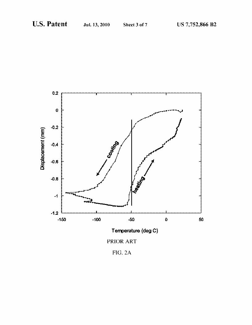
FIG. 2A labeled prior art depicts the performance of aspaceflight beyond low-Earth orbit. The United States and
known NiTiFe SM strip, while FIG. 2B depicts the perfor-
China have both declared an intention to establish human mance a non-solutionized extruded shape set SM spring com-habitation on the moon, and the United States intends even- 45 prising NTiFe according to an embodiment of the invention.tually to do so on Mars. Such extended human missions will
FIG. 3A depicts a differential scanning calorimetry (DSC)
require high-performance thermal conduction switches that response of a NiTiFe low-hysteresis SM spring according toprovide performance and reliability beyond those currently an embodiment of the invention.known, for applications such as methane or oxygen liquefac- FIG. 3B depicts the effect of shape setting temperaturetion or storage. Accordingly, there is a need for high-perfor- 5o according to an embodiment of the invention.mance, light, reliable and mechanically simple thermal con- FIG. 3C the effect of percentage reduction in area duringduction switches.
extrusion on the differential scanning calorimetry (DSC)response in a NiTiFe alloy, according to an embodiment of the
SUMMARY OF THE INVENTION
invention.55
This Summary is provided to comply with 37 C.F.R. § 1.73, DETAILED DESCRIPTION OF EMBODIMENTSpresenting a summary of the invention to briefly indicate the
OF THE INVENTION
nature and substance of the invention. It is submitted with theunderstanding that it will not be used to interpret or limit the The present invention is described with reference to thescope or meaning of the claims. 6o attached figures, wherein like reference numerals are used
In one embodiment of the invention, a thermal conduction throughout the figures to designate similar or equivalent ele-switch comprises a thermally-conductive stationary member ments. The figures are not drawn to scale and they are pro-having a first thermal contact and structure for securing the vided merely to illustrate the instant invention. Severalfirst member as a stationary member, a thermally-conductive aspects of the invention are described below with reference tomovable member having a second thermal contact, and a 65 example applications for illustration. It should be understoodlow-hysteresis shape memory (SM) comprising control
that numerous specific details, relationships, and methods are
spring interposed between the respective members. The set forth to provide a full understanding of the invention. One

US 7,752,866 B23
4having ordinary skill in the relevant art, however, will readily
The SM control member 104 shown as a control spring 104
recognize that the invention can be practiced without one or
in FIG. 1A is also interposed between the stationary plate 110more of the specific details or with other methods. In other and the movable plate 120. The thermal conduction switchinstances, well-known structures or operations are not shown
100 also comprises at least one deformable member 105
in detail to avoid obscuring the invention. The present inven- 5 shown in FIG. 1A as a bias spring 105. The bias spring 105tion is not limited by the illustrated ordering of acts or events, may generally be any type of spring and is operable to resistas some acts may occur in different orders and/or concur- the movable plate 120 moving away from or towards station-rently with other acts or events. Furthermore, not all illus- ary plate 110, such as a helical spring, and may be either atrated acts or events are required to implement a methodology compression or tension spring.in accordance with the present invention. 10 The thermally conductive coupler 106 shown in FIG. 1A
Embodiments of the present invention generally describe comprises a support rod that functions to guide the movementhigh-performance, light, reliable and mechanically simple of the movable plate 120 and conduct heat between the mov-thermal conduction switches. SM-based thermal conduction able plate 120 and the stationary plate 110. High thermalswitches according to embodiments of the invention typically conductivity greases (not shown) may be used to increaseprovide a phase change temperature <273 K, range of trans- 15 thermal conductivity between thermally conductive couplerformation <40 K such as <20 K, low hysteresis (e.g. <10 K), 106 and plates 110 and 120. The control springs 104 shown inand high displacement (>1 mm, such as about 2 to 4 mm). FIG. 1A are positioned radially outside the thermally conduc-FIG. 1A shows an exemplary thermal conduction switch 100
tive couplers 106.
including a SM control member 104 according to an embodi- In certain embodiments of the present invention, the shapement of the present invention. Thermal conduction switch 20 of the control spring 104 determines the distance between the100 comprises a thermally-conductive stationary first mem- plates 110 and 120 by switchably moving the movable plateber 110 shown as a stationary plate 110 having a first thermal
120. In such embodiments, when SM control member 104
contact 101, and a thermally-conductive movable second
comprises a control spring 104, upon phase change of the SMmember 120 shown as a movable plate 120 having a second
material the movable plate 120 moves such that the distance
thermal contact 103. First thermal contact 101 is shown com- 25 between the stationary plate 110 and movable plate 120prising an optional contact layer 101 of a high thermal con- changes by at least 1 mm.ductivity material that is different as compared to the material
In the embodiment shown in FIG. 1A, the control springs
comprising the stationary plate 110, such as a metal foil. 104 exert a force to separate the stationary plate 110 and theStationary plate 110 includes structure for securing the first movable plate 120, which is countered by the force that acts tomember as a stationary member shown in FIG. 1A as holes for 30 move the plates 110 and 120 toward one another (inward)mounting 119, such as for use with mounting fasteners (e.g. provided by the bias spring 105. In a typical embodiment, thescrews). force exerted outward by the control springs 104 is decreased
A thermally conductive coupler 106 is interposed between when the SM alloy of SM control spring 104 undergoes athe stationary plate 110 and the movable second plate 120 for phase change upon cooling. Following phase change, thethermally coupling the stationary plate 110 to the movable 35 force exerted by the bias spring 105 inward overcomes theplate 120. The thermally conductive coupler 106 is affixed to
force exerted by the control springs 104 outward, causing the
the stationary plate 110. Thermally conductive coupler 106
movable plate 120 to move towards the stationary plate 110can be formed from the same material as the stationary plate and thus retract from the body that is thermally regulated and110 or from another thermally conductive material. The mov- is generally cooler than the body requiring thermal regulationable plate 120 can have bearings 108 attached to it for 40 107. Other embodiments of the invention (not shown) cansmoother sliding with respect to the thermally conductive
include the control spring pulling in (tension springs) and the
coupler 106 which is generally affixed to stationary plate 110. bias spring pushing out (compression springs) and the ther-The stationary plate 110 is in constant thermal communica- mally regulated body being warmer than the body requiringtion with a body 107 that is either thermally regulated or thermal regulation.requiring thermal regulation. This present description of ther- 45 As known in the art after a sample of the SM material hasmal conduction switch 100 will assume body 107 requires
been deformed from its original configuration, it regains its
thermal regulation and will refer to this body as body requir- original geometry by itself in response to some trigger. Foring thermal regulation 107. example, the trigger can be temperature, an electric current,
As used herein, thermally conductive refers to a thermal
or a magnetic field. A suitable SM material may be an SMconductivity of at least 25 W/m•K at 300 K. In a first position, 5o alloy, SM polymer, or other SM material. It may be based onsuch as before or after phase change of the SM material
any of the main types of SM alloys. NiTi-based alloys gen-
provided by the SM control member 104, the second thermal
erally have the advantage of superior mechanical propertiescontact 103 of the movable plate 120 is in thermal commu- when compared to copper-based SM alloys. The copper SMnication with a thermally regulated body (not shown). As alloys generally have the advantage of lower cost. The SMdescribed above, in another embodiment of the invention the 55 material may also comprise NiTi alloys with Fe additions forposition and location of the thermally regulated body and the
low hysteresis phase transformations at low temperatures.
body requiring thermal regulation can be reversed (i.e. the
In the embodiment shown in FIG. 1A, when the SM mate-plate 110 can be in constant thermal communication with a rial undergoes phase change upon heating a shape changethermally regulated body while the plate 120 can be in swit- results, wherein the shape change results in the plates 110 andchable thermal communication with a body requiring thermal 60 120 separating further from one another. In a second position,regulation). such as after phase change upon cooling, the movable plate
In a typical embodiment, the stationary plate 110 is in
120 is no longer in thermal communication with the bodycontinuous contact with the body requiring thermal regula- requiring thermal regulation. Thus, thermal conductiontion 107 and the movable plate 120 is in periodic thermal
switch 100 is either thermally open or thermally closed
contact with a cooler body that is thermally regulated. For 65 depending on the phase-state of the SM control spring 104.example; heat transfer may occur between the warmer body
The spring shape of SM control spring 104 provides rela-
107 and the cooler body above a predetermined temperature. tively high stroke upon phase change. However, other shapes

US 7,752,866 B25
6ofthe SM control member 104 can generally be used. The SM
the SM material for the control spring 104 provides a low-
control member 104 can be any type of spring, including but
hysteresis phase change over a low-transformation range.not limited to helical springs, leaf springs, wave springs, The stationary plate 110 and movable plate 120 may gen-cantilevered springs, or torsion springs. The SM member 104
erally be made of any thermally conductive material. In
can also take other forms, such as a plurality of spring washers 5 embodiments ofthe present inventionthe stationary plate 110or one or more wires. In some embodiments of the present may be made of a thermally-conductive metal or alloy, suchinvention, the SM control member 104 is a helical spring, and
as a copper-beryllium alloy. An advantage of copper-beryl-
may be either compression or tension spring. Compression
lium alloys is the combination of high thermal conductivitysprings for control member 104 make thermal conduction and mechanical strength. However, the stationary plate 110switch 100 more shockresistant and not requiring mechanical io may generally comprise any suitable thermally conductivefastening. As used herein, compression springs are springs material. In some embodiments of the present invention thewhich expand upon heating as opposed to tension springs stationary plate 110 is in constant thermal communicationwhich compress upon heating. with the body requiring thermal regulation 107. As described
The SM control spring 104 coupled between the respective above the first thermal contact 101 of stationary plate 110members such as plates 110 and 120 can be coupled through 15 may comprise a contact layer 101 of a high thermal conduc-an intermediate material 109 that has a thermal conductivity tivity material that is different as compared to the materialthat is significantly different relative to the thermal conduc- comprising the stationary plate 110. Such a contact layer 101tivity of the respective members. As used herein, a "substan- may comprise a thermally conductive foil, that generallytially different' thermal conductivity is defined to be different provides a thermal conductivity of ?50 W/m•K. In oneby at least 10%: One function for the intermediate material 20 embodiment the contact layer 101 comprises an indium foil.with a thermal conductivity that is substantially different
At 300 K, indium provides a thermal conductivity of 81.8
from the respective members is to influence the thermal gra- W/m•K. Such a contact layer may also be placed above thedient in the SM control spring 104 that occurs during normal
movable plate 120.
operation when switch 100 is thermally closed. In one
The contact layer 101 may be connected to the stationaryembodiment the intermediate material 109 comprises a rela- 25 plate 110 or the movable plate 120 by various methods knowntively low thermal conductivity material such as polytet- to those skilled in the art. The stationary plate 110 or movablerafluoroethylene (TEFLON(k) which has a thermal conduc- plate 120 may generally be of any shape that providestivity at 300 K of about 0.23 W/m•K. The thermal
adequate thermal conduction between them and their contact-
conductivity of polytetrafluoroethylene is at least two (2)
ing thermal bodies, and that provides adequate thermal con-orders of magnitude lower as compared to metals which 3o duction between the stationary plate 110 and the movablenormally comprise the first and second members. As shown in plate 120. Typically, the surfaces can be chosen to achieve theFIG. 1A, the intermediate material 109 serves to thermally required thermal conductivity. If higher thermal conductivelycouple the control spring 104 to the stationary plate 110 and
is desired the respective surfaces can be mated in a non-planar
thereby alter the thermal gradient that develops in control
fashion using hill and valley, curved or ridged morphologiesspring 104 during operation of switch 100 when closed. The 35 to maximize the contact area. Those having ordinary skill incoupling of the control spring 104 between the first member the art are capable of varying the shape and surface of thesuch as stationary 110 and the second member such as mov- stationary plate 110 and the movable plate 120 as needed forable plate 120 through the intermediate material 109 can be in the particular application.series with the control spring 104 with the intermediate mate- FIG. 1B simplified depiction of an exemplary thermal con-rial either placed between the first member 110 and the con- 4o duction switch 150 in a series setup according to an embodi-trol spring 104 or the second member 120 and the control
ment of the present invention. In the series setup shown the
spring 104, or both. bias spring 105 is coupled to act in-line with the controlAs shown in FIG. 1A, the control springs 104 are arranged
member 104, such as an SM control spring 104. The principle
in a triangular fashion, each control spring 104 occupying the of operation of thermal conduction switch 150 is identical tocorner of conceptual equilateral triangle. Although three (3) 45 that of the parallel setup shown in FIG. 1A and describedcontrol springs 104 are shown in FIG. 1A, generally any above but is advantageous in situations where the switch hasnumber of control springs 104 in any configuration may be to be compact and contained and possess a smaller footprint.used. If a plurality of control springs are present the thermal
In embodiments of the present invention the SM material
conduction switch 100 will generally have increased reliabil- for the control spring 104 is a low hysteresis low transforma-ity and increased contact force between the movable plate 120 50 tion range SM material, as these materials have the advantageand the thermal body, although as few as one control spring of short cycle times and high precision. "Hysteresis" in the104 may be adequate in some embodiments. If more than one context of SM alloys as used herein refers to the difference incontrol spring 104 is present, the control springs 104 may be temperatures between the temperature at which phase changeof varying dimensions and compositions. However, perfor- occurs upon heating and the temperature at which phasemance will generally be enhanced and simplified if all control 55 change occurs upon cooling. "Low hysteresis" in the contextsprings have substantially the same dimension and SM com- of SM materials means a material in which the temperature atposition. Springs have one advantage of significantly higher which phase change occurs upon heating is relatively close tostroke as opposed to different forms of SM material actuator, the temperature at which phase change occurs upon cooling.such as strips. Helical springs particularly tend to provide
Typical hysteresis associated with known SM alloys is gen-
very high stroke. Simpler forms of actuators, such as strips, 60 erally in the range of 20-40° C., or more (See FIG. 2Ahave an advantage of ease of manufacture, but generally have
described below). Low hysteresis SM alloys according to the
much lower stroke than springs. embodiments of the present invention generally have muchThe control spring 104 generally comprises a SM alloy, lower hysteresis, defined herein to be <10' C. (<10 K), such
such as of the NiTiFe type. In further embodiments of the as <5 K, and in certain embodiments <2 K, or <1 K. Trans-invention the control spring 104 comprises an SM material 65 formation temperature range refers to the difference betweenthat undergoes a phase change at low temperature such as the start of the transformation and the finish of the transfor-from 15K to 273K. In further embodiments of the invention mation. Typical transformation temperature ranges associ-

US 7,752,866 B27
8ated with known SM alloys in use are generally in the range of
higher than conventional shape setting temperatures provides
25-60 K, or more (See FIG. 2A described below). Low trans- a significantly higher density of defects as compared to con-formation temperature range SM alloys according to the ventional solutionized extruded wire shape set at lower tem-embodiments of the present invention generally have much
perature. Higher defect density has been found to allow
lower transformation temperature range, defined herein to be 5 achieving low temperature low hysteresis phase change with-<20 K, such as <15 K. In embodiments of the present inven- out increasing transformation temperature range. Whiletion, the SM control spring 104 also provides high displace- increased dislocation densities can reduce the hysteresis (de-ment upon phase change. As described above, in the case of
sirable) they can also increase the transformation temperature
linear spring displacement, the displacement provided by the range (undesirable).control spring 104 is generally at least 1 mm. In some io Conventional solutionized extruded SM wire generallyembodiments, the displacement is over about 2 mm, and in provides dislocation densities <10 5/cm2 . The higher level ofsome embodiments the displacement is >4 mm, such as metallurgical defects obtained from shape set unsolutionizedbetween about 4 or 5 mm. As described in the Examples extruded wire, such as a dislocation density of ?105/cm2,below, FIG. 2B shows a SM control spring 104 according to typically ? 10 $/cm2 has been found by the Present Inventorsan embodiment of the invention which provides <2 K hyster- 15 to significantly reduce hysteresis, such as to a level <2 Kesis, <15 K transformation temperature range and above 4
while keeping the transformation temperature range to <15 K.
mm of displacement. This low hysteresis low transformation range level can beIn embodiments of the present invention the SM material i s compared to hysteresis and transformation range levels for a
a low-temperature phase change material. Low-temperature conventional NiTiFe SM strip (See FIG. 2A describedphase change SM materials undergo phase change (and thus 20 below).a shape change) at temperatures typically below 273 K. Some
In embodiments of the present invention, the body requir-
low-temperature phase change SM materials undergo phase
ing thermal regulation 107 and the second body that is ther-change in temperature ranges from 15-273 K, or more nar- mally regulated may generally be any structure or mechanismrowly from 250-270 K. Some low-temperature phase change that benefits from thermal regulation or is useful in thermalSM materials according to the invention undergo phase 25 regulation. Examples of such bodies include but are not lim-change at temperature ranges as low as 15-120 K, and in one
ited to heat sinks, heat sources, or dewars of liquified gasses
embodiment is in the range from 116-122 K. (such as oxygen or methane). In one embodiment of theSuch low phase-change temperatures have been recog- invention the thermal conduction switch is used to achieve
nized by the Present Inventors to be achieved by varying the
liquefaction of a cryogen (such as methane) through periodicamount of Fe and the ratio of Ni to Ti in an NiTiFe SMA. In 30 thermal contact between a reservoir of the cryogen and aone particular embodiments of the invention, the temperature reservoir of another cryogen that is thermally regulated (suchof phase-change is lowered by including at least 3.2% Fe. as oxygen).Generally, it has been found that the addition of Fe to a NiTiSM material lowers the temperature at which phase-change
EXAMPLESwill occur. An advantage of low-temperature phase change 35
SM materials is their utility in thermal conduction switches The following non-limiting Examples serve to illustrate
that control very low temperature systems, such as liquified selected embodiments of the invention. It will be appreciated
gasses. that variations in proportions and alternatives in elements ofThe switch will generally be of higher precision and per- the components shown will be apparent to those skilled in the
formance if the alloy has very low hysteresis and low trans- 40 art and are within the scope of embodiments of the presentformation temperature range, and the alloy's temperature of
invention.
phase change upon heating and temperature of phase change FIG. 2A labeled prior art depicts the performance of a
upon cooling are within 2 K of one another and the transfor- known NiTiFe SM strip. The known SM strip evidences amation temperature range <15 K. The switch will be of even
hysteresis of at least 30 K, range of transformation of abouthigher precision and performance if the alloy's temperature 45 100 K, and a displacement of no more than about 1 mm. FIG.of phase change upon heating and temperature of phase
2B depicts the performance a SM spring comprising NiTiFechange upon cooling are within 1 K of one another. The SM
according to an embodiment of the invention. The SM springalloy may achieve phase-change between about 240-280 K, was shape set at high temperature and was not solutionized oror alternatively between 260-270 K, 92 and 120 K, or subjected to any ageing treatment. The shape-set was per-between 118 and 120 K. In further embodiments of the 50 formed at 520° C. for 20 minutes followed by an ice-waterpresent invention, the alloy comprises NiTiFe having an Fe %
quench. Upon heating, the SM spring is shown to lengthenof at least 2 atomic %, such as substantially the composition relative to its length below the phase change temperature. TheN147.07T149.66Fe3.27 hysteresis shown in FIG. 2B is <2 K, the range of transfor-
In embodiments of the present invention, particular ther- mation is <20 K and the displacement shown is around 4 mm.momechanical processing is used to form SM springs accord- 55 This relatively long displacement length helps in achievinging to the invention. The control spring 104 can be made from enhanced thermal isolation in the thermally open state and anextruded SM wire. In further embodiments of the present ability to tailor the contact force over the displacement length.invention, the wire is only shape set and is not solutionized or
The utilization of the cubic (austenite) to trigonal (R-phase)subjected to ageing treatment. The shape-set can be at about phase transformation in NiTiFe shape memory alloys is520 to 600° C., such as 550° C., for 15 to 25 minutes, such as 6o believed to be responsible for the reduced transformation20 minutes, followed by an ice-water quench. Conventional
hysteresis. However, embodiments of the invention may be
shape setting temperature are known to be at a lower tempera- practiced without the theoretical aspects presented. More-ture, such as between 400° C. to 500° C. for binary NiTi
over, the theoretical aspects are presented with the under-alloys. standing thatApplicants do not seek to be bound by the theory
The Present Inventors have recognized through experi- 65 presented.ments similar to those depicted in FIG. 3B and FIG. 3C that
FIG. 3A depicts a differential scanning calorimetry (DSC)
unsolutionized extruded wire shape set at the above described
response of a NiTiFe low-hysteresis SM spring according to

US 7,752,866 B29
an embodiment of the invention. The results show the auste-nite to Rphase transformation during cooling and the reversetransformation during heating. The first curve, represented bythe darker line, is the NiTiFe wire (as received) before anyprior heat treatment. The second curve, represented by thelighter line, received a heat treatment of 793 K for 20 minutesduring the shape-setting procedure and was subsequentlyice-water quenched. A slightly sharper peak resulted after theheat treatment, for both the austenite to R-phase transfonna-tion and the reverse transformation indicative of a reductionin the transformation. FIG. 3B illustrates the effect of shapesetting temperature and FIG. 3C illustrates the effect of per-centage reduction in area during extrusion on the differentialscanning calorimetry (DSC) response in a NiTiFe alloy,respectively, according to embodiments of the invention.These FIGS. show the complex effects of these parameters onthe phase transformation.
While various embodiments of the present invention havebeen described above, it should be understood that they havebeen presented by way of example only, and not limitation.Numerous changes to the disclosed embodiments can bemade in accordance with the disclosure herein withoutdeparting from the spirit or scope of the invention. Thus, thebreadth and scope of the present invention should not belimited by any of the above described embodiments. Rather,the scope of the invention should be defined in accordancewith the following claims and their equivalents.
Although the invention has been illustrated and describedwith respect to one or more implementations, equivalentalterations and modifications will occur to others skilled inthe art upon the reading and understanding of this specifica-tion and the annexed drawings. In addition, while a particularfeature of the invention may have been disclosed with respectto only one of several implementations, such feature may becombined with one or more other features of the other imple-mentations as may be desired and advantageous for any givenor particular application.
The terminology used herein is for the purpose of describ-ing particular embodiments only and is not intended to belimiting of the invention. As used herein, the singular forms"a", "an" and "the" are intended to include the plural forms aswell, unless the context clearly indicates otherwise. Further-more, to the extent that the terms "including", "includes","having", "has", "with", or variants thereof are used in eitherthe detailed description and/or the claims, such terms areintended to be inclusive in a manner similar to the term"comprising."
Unless otherwise defined, all terms (including technicaland scientific terms) used herein have the same meaning ascommonly understood by one of ordinary skill in the art towhich this invention belongs. It will be further understoodthat terms, such as those defined in commonly used dictio-naries, should be interpreted as having a meaning that isconsistent with their meaning in the context of the relevant artand will not be interpreted in an idealized or overly formalsense unless expressly so defined herein.
The Abstract of the Disclosure is provided to comply with37 C.F.R. §1.72(b), requiring an abstract that will allow thereader to quickly ascertain the nature of the technical disclo-sure. It is submitted with the understanding that it will not beused to interpret or limit the scope or meaning of the follow-ing claims.
We claim:1. A thermal conduction switch, comprising:a thermally-conductive first member having a first thermal
contacting surface, comprising a structure for securing
10said first member as a stationary member to a thermallyregulated body or a body requiring thermal regulation;
a movable thermally-conductive second member having asecond thermal contacting surface,
5 a thermally conductive coupler interposed between saidfirst member and said second member for thermallycoupling said first member to said second member;
at least one control spring coupled between said first mem-ber and said second member, wherein said control spring
10 comprises a NiTiFe comprising shape memory (SM)material that provides a phase change at a temperature<273 K, a transformation range <40 K and a hysteresisof <10 K, and
a bias spring between said first member and said secondis member, wherein said phase change provides a distance
change between said first and said second member by atleast 1 mm.
2. The thermal conduction switch of claim 1, wherein said20 bias spring and said control spring are arranged parallel to one
another.3. The thermal conduction switch of claim 1, wherein said
bias spring and said control spring are arranged in series toone another.
25 4. The thermal conduction switch of claim 1, wherein saidcontrol spring comprises a compression spring.
5. The thermal conduction switch of claim 1, wherein saidcontrol spring comprises a tension spring.
6. The thermal conduction switch of claim 1, wherein said30 SM material comprises at least 2 atomic % Fe.
7. The thermal conduction switch of claim 1, wherein saiddistance change is >2 mm, said transformation range is <20 Kand said hysteresis is <2 K.
8. The thermal conduction switch of claim 1, further com-35 prising a contact layeron said firstmemberthat has a different
composition as compared to material comprising said firstmember.
9. The thermal conduction switch of claim 8, wherein saidcontact layer comprises a metal foil that provides a thermal
40 conductivity at 300 K of ?50 W/m•K.10. The thermal conduction switch of claim 1, further
comprising a contact layer on said second member that has adifferent composition as compared to a material comprisingsaid second member.
45 11. The thermal conduction switch of claim 10, whereinsaid contact layer comprises a metal foil that provides athermal conductivity at 300 K of ?50 W/m•K.
12. The thermal conduction switch of claim 1, wherein said
SoSM material comprises at least 3 atomic % Fe and said controlspring comprises unsolutionized extruded SM wire, saidunsolutionized extruded shape set SM wire shape set havinga dislocation density ?105/cm2.
13. The thermal conduction switch of claim 12, wherein
55 said dislocation density is ?10$/cm2.
14. The thermal conduction switch of claim 13, whereinsaid SM material comprises substantiallyN147.07T149.66Fe3.27
15. The thermal conduction switch of claim 1, further60 comprising an intermediate material that has a thermal con-
ductivity that is substantially different from respective mate-rials comprising both said first member and said second mem-ber, interposed between said control spring and at least one ofsaid first and said second member.
65 16. A method of transferring heat between a first thermallyregulated body and a second thermal body requiring thermalregulation, comprising:

US 7,752,866 B211
thermally and physically securing one of said first andsecond bodies to a first thermally conductive member,wherein said physical coupling renders said first mem-ber a stationary member;
thermally coupling the other of said first and second bodiesto a second thermally conductive member, wherein saidother of said first and second bodies is not secured to saidsecond member to render said second member a mov-able member;
coupling at least one shape memory (SM) control springbetween said stationary member and saidmovablemem-her, wherein said control spring comprises a NiTiFecomprising SM material that provides a phase change ata temperature <273 K with a transformation range <40 Kand a hysteresis of <10 K, wherein said phase changeprovides a distance change between said first and saidsecond plates of at least 1 mm, and
transferring heat between said first and second bodieswhen the temperature of either of said first and secondbodies is below said phase change temperature.
1217. The method of claim 16, wherein said distance change
is >2 mm, said transformation range is <20 K and said hys-teresis is <2 K.
18. The method of claim 17, wherein said SM material5 comprises at least 3 atomic % Fe and said control spring
comprises unsolutionized extruded SM wire, said unsolution-ized extruded SM wire shape set having a dislocation density
105/cm2.19. The method of claim 16, wherein said control spring is
io thermally coupled to at least one of said stationary memberand said movable member through an intermediate materialthat has a thermal conductivity that is substantially differentfrom respective materials comprising both said stationarymember and said movable member.
15 20. The method of claim 16, wherein said phase changetemperature is in the range from 116-122 K and said first andsecond bodies comprise liquid oxygen and liquid methane,respectively.