Embed Size (px)
Citation preview
[email protected] Paper 86 571-272-7822 Entered: May 9, 2016
UNITED STATES PATENT AND TRADEMARK OFFICE ____________
BEFORE THE PATENT TRIAL AND APPEAL BOARD
____________
ZHONGSHAN BROAD OCEAN MOTOR CO., LTD., BROAD OCEAN MOTOR LLC, and
BROAD OCEAN TECHNOLOGIES, LLC, Petitioner,
v.
NIDEC MOTOR CORPORATION, Patent Owner. ____________
Case IPR2014-011211 Patent 7,626,349 B2
____________ Before SALLY C. MEDLEY, JUSTIN T. ARBES, BENJAMIN D. M. WOOD, JAMES A. TARTAL, and PATRICK M. BOUCHER, Administrative Patent Judges. BOUCHER, Administrative Patent Judge.
FINAL WRITTEN DECISION 35 U.S.C. § 318(a) and 37 C.F.R. § 42.73
1 Case IPR2015-00762 has been joined with this proceeding.
IPR2014-01121 Patent 7,626,349 B2
2
I. INTRODUCTION
A. Background
The trial in this proceeding resulted from the filing of two petitions by
Zhongshan Broad Ocean Motor Co., Ltd., Broad Ocean Motor LLC, and
Broad Ocean Technologies, LLC (collectively, “Petitioner”). First, in
response to a corrected petition (Paper 72, “Pet. 1121”) filed in IPR2014-
01121, the Board instituted trial with respect to the following ground of
unpatentability: claims 1–3, 8, 9, 12, 16, and 19 as unpatentable under
35 U.S.C. § 103(a) over U.S. Patent No. 5,410,230 (Ex. 1006, “Bessler”)
and Peter Franz Kocybik, Electronic Control of Torque Ripple in Brushless
Motors (University of Plymouth, July 2000) (Ex. 1007, “Kocybik”). Paper
20, 17. Second, in response to the concurrent filing in IPR2015-00762 of a
petition (IPR2015-00762, Paper 3, “Pet. 762”) and a Motion for Joinder
(IPR2015-00762, Paper 4), the Board instituted trial with respect to the
following ground of unpatentability, and joined IPR2015-00762 with
IPR2014-01121: claims 1–3, 8, 9, 12, 16, and 19 as anticipated under
2 Unless otherwise indicated, citations are to IPR2014-01121. In some instances, the parties filed papers under seal with concurrently filed public redacted versions; unless otherwise indicated, citations are to public versions of the papers.
IPR2014-01121 Patent 7,626,349 B2
3
35 U.S.C. § 102(b) by JP 2003-348885 (Ex. 10033, “Hideji”). Paper 67, 9–
10. Patent Owner timely filed Patent Owner Responses. Papers 30, 72.
Petitioner timely filed Replies to the Patent Owner Responses. Papers 36,
78. An oral hearing was held on February 23, 2016. Paper 85 (“Tr.”).
We have jurisdiction under 35 U.S.C. § 6(c). This Decision is a Final
Written Decision under 35 U.S.C. § 318(a) as to the patentability of the
claims on which we instituted trial. Based on the record before us, Petitioner
has shown, by a preponderance of the evidence, that claims 1–3, 8, 9, 12, 16,
and 19 are unpatentable.4
B. The ’349 Patent (Ex. 1001)
The ’349 patent relates to heating, ventilating, and/or air conditioning
(“HVAC”) systems that use air-moving components, such as a blower.
Ex. 1001, col. 1, ll. 8–11. Figure 4 of the ’349 patent is reproduced below.
3An unattested English translation of Hideji was filed as Ex. 1005 in IPR2014-01121. An attested English translation of Hideji was filed as Ex. 1005 in IPR2015-00762. Except for the attestation, the translations are identical. Accordingly, to simplify citation to the record, we subsequently cite to Ex. 1005 of IPR2014-01121 for citations to Hideji. 4 Judges Wood and Boucher disagree with Judges Medley, Arbes, and Tartal that 35 U.S.C. § 315(c) permits issues presented in IPR2015-00762 to have been joined to IPR2014-01121. Paper 67 (Boucher, APJ, dissenting).
IPR2014-01121 Patent 7,626,349 B2
4
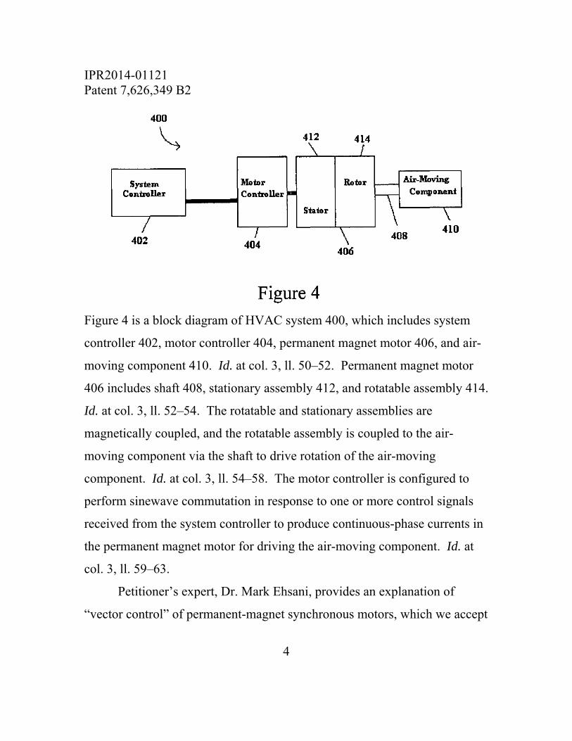
Figure 4 is a block diagram of HVAC system 400, which includes system
controller 402, motor controller 404, permanent magnet motor 406, and air-
moving component 410. Id. at col. 3, ll. 50–52. Permanent magnet motor
406 includes shaft 408, stationary assembly 412, and rotatable assembly 414.
Id. at col. 3, ll. 52–54. The rotatable and stationary assemblies are
magnetically coupled, and the rotatable assembly is coupled to the air-
moving component via the shaft to drive rotation of the air-moving
component. Id. at col. 3, ll. 54–58. The motor controller is configured to
perform sinewave commutation in response to one or more control signals
received from the system controller to produce continuous-phase currents in
the permanent magnet motor for driving the air-moving component. Id. at
col. 3, ll. 59–63.
Petitioner’s expert, Dr. Mark Ehsani, provides an explanation of
“vector control” of permanent-magnet synchronous motors, which we accept

IPR2014-01121 Patent 7,626,349 B2
5
as an accurate description of the understanding of one of ordinary skill in the
art. Dr. Ehsani explains that “[t]he concept of vector control, which
typically uses d and [Q] current components, arises from [a] principle [in
which] torque arrives from the interaction of two magnetic fields, one
originating from the stator and one originating from the rotor.” Ex. 1009
¶ 13. The drawing from page 6 of Dr. Ehsani’s Declaration is reproduced
below.
The drawing from Dr. Ehsani’s Declaration illustrates a rotor, which has a
permanent magnet having north and south poles Nr and Sr, respectively, and
illustrates a stator, which includes electromagnets that result in a virtual
IPR2014-01121 Patent 7,626,349 B2
6
stator magnet having north and south poles Ns and Ss, respectively. Id. ¶ 15.
The d axis is aligned with the rotor and the Q axis5 is offset 90° from the d
axis. The motor commutates the winding currents to maintain orthogonality
of the d and Q axes as the rotor turns. Id. ¶ 16.
The Specification of the ’349 patent provides sparse details of how
vector control is achieved in the context of the claimed invention. Figure 8
of the ’349 patent is reproduced below, with reference numbers in red added
by the Board.
5 Dr. Ehsani uses a lower-case letter q in referring to this axis. We use an upper-case letter Q for consistency with the claims that are before us.
IPR2014-01121 Patent 7,626,349 B2
7
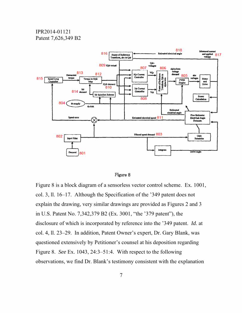
Figure 8 is a block diagram of a sensorless vector control scheme. Ex. 1001,
col. 3, ll. 16–17. Although the Specification of the ’349 patent does not
explain the drawing, very similar drawings are provided as Figures 2 and 3
in U.S. Patent No. 7,342,379 B2 (Ex. 3001, “the ’379 patent”), the
disclosure of which is incorporated by reference into the ’349 patent. Id. at
col. 4, ll. 23–29. In addition, Patent Owner’s expert, Dr. Gary Blank, was
questioned extensively by Petitioner’s counsel at his deposition regarding
Figure 8. See Ex. 1043, 24:3–51:4. With respect to the following
observations, we find Dr. Blank’s testimony consistent with the explanation
IPR2014-01121 Patent 7,626,349 B2
8
of Figures 2 and 3 of the ’379 patent provided by the Specification of the
’379 patent, and accept Dr. Blank’s testimony as an accurate description of
what one of ordinary skill in the art would understand from Figure 8.
Demand 801 provides a speed demand as a source of power for the
motor drive, which is filtered by input filter 802 to provide filtered speed
demand 803. Ex. 1043, 24:23–25:25. The power to drive the motor
originates from dc-supply 804 and is supplied to pulse width modulation
engine 805, which converts a direct-current signal into alternating current
voltages, and controls the magnitude of those voltages by varying the width
of the pulse. Id. at 26:24–27:18. Such control is effected by using an α-β
voltage demand generated by frame of reference transform 806 using VQr
and Vdr signals, as well as an estimated electrical angle. Id. at 27:19–29:8.
The VQr and Vdr signals are supplied respectively by IQr current controller
807 and Idr current controller 808, which receive “IQdr actual” signal 809,
“IQdr demand” signal 810, and estimated electrical speed 811 derived from
filtered speed demand 803. Id. at 30:20–31:3, 32:10–18. The “IQdr actual”
signal is a combination of signals along the Q and d axes, and the “IQdr
demand” signal results from a conversion performed by torque to IQdr map
812 using demanded torque 813 (provided by speed loop controller 815,
which is part of the motor controller) and Idr demand 814. Id. at 31:4–24,
26:18–23. The “IQdr actual” signal 809 is determined by frame of reference
transform 816 from measured current and applied voltage 817, as well as
estimated electrical angle 818. Id. at 65:6–66:11.
IPR2014-01121 Patent 7,626,349 B2
9
C. Illustrative Claim
Claim 1 of the ’349 patent is illustrative of the claims at issue:
1. A heating, venting and/or air conditioning (HVAC) system comprising a system controller, a motor controller, an air-moving component, and a permanent magnet motor having a stationary assembly, a rotatable assembly in magnetic coupling relation to the stationary assembly, and a shaft coupled to the air-moving component, wherein the motor controller is configured for performing sinewave commutation, using independent values of Q and d axis currents, in response to one or more signals received from the system controller to produce continuous phase currents in the permanent magnet motor for driving the air-moving component.
II. ANALYSIS
A. Claim Construction
The Board interprets claims of an unexpired patent using the broadest
reasonable construction in light of the specification of the patent in which
they appear. See 37 C.F.R. § 42.100(b); In re Cuozzo Speed Techs., LLC,
793 F.3d 1268, 1278 (Fed. Cir. 2015) (“We conclude that Congress
implicitly approved the broadest reasonable interpretation standard in
enacting the AIA”), cert. granted sub nom. Cuozzo Speed Techs., LLC v.
Lee, 136 S. Ct. 890 (mem.) (2016).
IPR2014-01121 Patent 7,626,349 B2
10
1. Preambles
Patent Owner contends that “[t]he preambles of the challenged claims,
requiring an ‘HVAC system,’ are limiting.” Paper 30, 8. We disagree that
the “HVAC system” portions of the preambles are limiting.6
“Generally, . . . the preamble does not limit the claims.” DeGeorge v.
Bernier, 768 F.2d 1318, 1322 n.3 (Fed. Cir. 1985). In particular, “[t]he
preamble of a claim does not limit the scope of the claim when it merely
states a purpose or intended use of the invention.” In re Paulsen, 30 F.3d
1475, 1479 (Fed. Cir. 1994) (citing DeGeorge, 768 F.2d at 1322 n.3). In
this instance, the “HVAC system” portions of the preambles of the
challenged claims provide no antecedents for ensuing claim terms, with the
bodies of the claims neither repeating nor referencing HVAC systems.
Because the language in the bodies of the claims, standing alone, is
sufficient to set forth the invention, the “HVAC system” portions merely
provide a stated purpose for the invention. Accordingly, we find no
6 Independent claim 1 recites a “heating, ventilating and/or air conditioning (HVAC) system.” Independent claim 16 recites a “blower assembly for a heating, ventilating and/or air conditioning (HVAC) system.” Independent claim 19 recites a “method for driving an air-moving component of a heating, ventilating and/or air conditioning (HVAC) system in response to a control signal, the HVAC system including a permanent magnet motor having a stationary assembly and a rotatable assembly in magnetic coupling relation to the stationary assembly, said rotatable assembly coupled in driving relation to the air-moving component.”
IPR2014-01121 Patent 7,626,349 B2
11
compelling reason to afford weight to the “HVAC system” language in the
preambles.
2. “using independent values of Q and d axis currents”
In the Institution Decisions, the Board construed “using independent
values of Q and d axis currents,” which is recited in independent claims 1,
16, and 19, as requiring the use of Q and d axis current values that are
developed independently of each other, without relying on one to derive the
other. Paper 20, 7–8; IPR2015-00762, Paper 12, 6–7. Patent Owner does
not explicitly contest this construction, and advocated for this construction in
its Preliminary Responses. Paper 14, 9–10; IPR2015-00762, Paper 10, 19.
But Patent Owner presents arguments that implicitly construe the phrase as
requiring the use of independent demand Q and d axis currents, rather than
the use of independent actual Q and d axis currents. See Paper 72, 6, 8.
The phrase was added to the claims during prosecution, and Petitioner
contends that it refers to the actual Q and d axis currents, noting the
patentee’s representation that support for the limitation “can be found,
among other places, in Fig. 8 of the instant application as filed.” Paper 78,
8–9 (quoting Ex. 1002, 16). Petitioner observes that, in Figure 8 of the ’349
patent (reproduced above), “[t]he ‘estimated electrical angle’ and ‘measured
current and applied voltage’ signals [818 and 817] are input to the ‘Frame of
Reference transform, abc to Qdr’ [816], which outputs the ‘IQdr actual’
signal [809].” Id. at 10. The ’379 patent, incorporated by reference into the
IPR2014-01121 Patent 7,626,349 B2
12
’349 patent, addresses decoupling of the IQdr components in producing
torque:
The decoupling of IQdr components in the production of torque can be applied within either a sensorless control system or a sensor-controlled system. If a given motor does not show any discernible hybrid behavior, the control technique can default to that classically used with a [permanent-magnet] motor (i.e., Idr torque contribution assumed to be zero) where the torque contribution comes from IQr.
Ex. 3001, col. 6, ll. 1–7. Petitioner’s position that these IQdr components
refer to the actual Q and d axis currents, rather than the demand Q and d axis
currents, is supported by the above disclosure as well as by Dr. Ehsani’s
testimony that, in an ideal permanent-magnet, it is the actual d axis current
value that is assumed to be zero. See Ex. 1009 ¶¶ 18–19.
We clarify our construction of “using independent values of Q and d
axis currents” as requiring the use of actual Q and d axis current values that
are developed independently of each other, without relying on one to derive
the other.
3. “back-emf . . . motor”
In the Institution Decisions, the Board construed “back-emf . . .
motor,” which is recited in claim 9, as coterminous with “permanent magnet
motor.” Paper 20, 7–8; IPR2015-00762, Paper 12, 6–7. Neither party
contests that construction and we adopt it for this Final Written Decision.

IPR2014-01121 Patent 7,626,349 B2
13
B. Petitioner’s Motion to Exclude
Petitioner filed a Motion to Exclude portions of Exhibit 2003 and the
entirety of Exhibits 2010, 2011, and 2018–2025. Paper 50. But as Patent
Owner contends, Petitioner’s Motion does not address Patent Owner’s
timely supplementation of the challenged evidence pursuant to 37 C.F.R.
§ 42.64(b)(2). Paper 54, 1. Patent Owner contends that the supplemental
evidence is curative and that “[b]ecause Petitioners do not argue in their
motion that [Patent Owner’s] supplemental evidence failed to cure the
deficiencies they identify (or is deficient in any other way), Petitioners have
waived any argument regarding the sufficiency of the supplemental
evidence.” Id. (citing 37 C.F.R. § 42.23(b)). Petitioner counters that Patent
Owner failed to seek authorization to file its supplemental evidence or its
Opposition: “The Board should therefore ignore both Patent Owner’s
supplemental evidence and its Opposition because it failed to seek
authorization from the Board beforehand.” Paper 68, 1–2 (citing Gnosis
S.P.A. v. South Alabama Med. Sci. Found., Case IPR2013-00116, Paper 29,
3 (October 9, 2013)).
Petitioner’s argument does not accurately reflect the requirements of
the Board’s rules governing inter partes review proceedings. Once a trial
has been instituted, any objection to evidence must be filed within five
business days of service of the evidence and must identify the grounds for
the objection “with sufficient particularity to allow correction in the form of
supplemental evidence.” 37 C.F.R. § 42.64(b)(1). The party relying on the
IPR2014-01121 Patent 7,626,349 B2
14
evidence to which an objection is timely served is then provided an
opportunity to correct, by serving supplemental evidence within ten business
days of service of the objection. See 37 C.F.R. §§ 42.64(b)(1), 42.64(b)(2).
If, upon receiving the supplemental evidence, the opposing party is still of
the opinion that the evidence is inadmissible, the opposing party may file a
motion to exclude such evidence. Service of such supplemental evidence
does not require Board authorization, nor does filing of an opposition to a
motion to exclude. 37 C.F.R. §§ 42.23, 42.64(b)(2), 42.64(c). Nothing in
the Gnosis order cited by Petitioner stands for any contrary proposition.
Indeed, the Scheduling Orders for this proceeding explicitly set forth
deadlines for filing oppositions to motions to exclude. Paper 21, 4; Paper
70, 4.
We have considered the parties’ arguments, but need not reach the
merits of Petitioner’s Motion to Exclude because, as explained below, even
if the disputed evidence is considered, Patent Owner has not shown proof of
secondary considerations that would support a conclusion of nonobviousness
of the challenged claims. Accordingly, Petitioner’s Motion to Exclude is
dismissed as moot.
C. Patent Owner’s Motion to Exclude
Patent Owner filed a Motion to Exclude portions of Exhibit 1020 and
the entirety of Exhibits 1034 and 1035. Paper 53. As Petitioner points out,
Patent Owner failed to follow the correct procedure to preserve its objections
IPR2014-01121 Patent 7,626,349 B2
15
to Petitioner’s evidence. See Paper 58, 1–2. On May 19, 2015, the Office
amended 37 C.F.R. § 42.64(b)(1) in a final rule-making notice to require that
objections be “filed” rather than “served” within five business days of
service of evidence to which the objections are directed. 80 Fed. Reg.
28,561, 28,563 (May 19, 2015). Patent Owner acknowledges that it served
its objections on Petitioner on August 28, 2015, but did not file them until
September 21, 2015 “in accordance with established practice under the
former version of 37 C.F.R. § 42.[64](b)(1).” Paper 65, 1.
Patent Owner requests that, in view of the rule change, we exercise
our discretion under 37 C.F.R. § 42.5(b) to waive or suspend the
requirement of the version of 37 C.F.R. § 42.64(b)(1) in effect at the relevant
time. Id. at 2. We do not question the sincerity of Patent Owner’s
representations that it “was admittedly unaware” of the rule change and that
its errors “were honest mistakes on its part.” Paper 65, 1–2. Those
representations are relevant. Nevertheless, in considering Patent Owner’s
request, we are mindful of the history of this proceeding and guided by
considerations of fairness. Patent Owner has benefited from our previous
strict enforcement of 37 C.F.R. § 42.63(b) over strenuous efforts by
Petitioner—including a request that we exercise our discretion under 37
C.F.R. § 42.5—to correct Petitioner’s failure to include an affidavit attesting
to the accuracy of the English translation of Hideji with its original filing in
IPR2014-01121. See Paper 25. In this context, we decline to use our
discretionary authority to excuse Patent Owner’s error.
IPR2014-01121 Patent 7,626,349 B2
16
Accordingly, we dismiss Patent Owner’s Motion to Exclude.7
D. Obviousness Over Bessler and Kocybik
Petitioner contends that claims 1–3, 8, 9, 12, 16, and 19 are
unpatentable over Bessler and Kocybik under 35 U.S.C. § 103(a). Pet. 1121,
4. Bessler discloses an HVAC system that uses an electronically
commutated motor (“ECM”). Ex. 1006, col. 4, ll. 11–13. In challenging
independent claim 1, Petitioner contends that Bessler discloses all
limitations but one, acknowledging that “Bessler does not explicitly disclose
the use of sine wave commutation and independent [Q]- and d- axis
currents.” Pet. 1121, 36. For the limitation that recites such features,
Petitioner relies on Kocybik, noting that, like Bessler, Kocybik discloses an
ECM. Id. at 41–46.
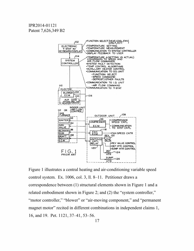
Figure 1 of Bessler is reproduced below.
7 Alternatively, the Motion would be dismissed because we do not rely on the evidence sought to be excluded in this Decision.
IPR2014-01121 Patent 7,626,349 B2
17
Figure 1 illustrates a central heating and air-conditioning variable speed
control system. Ex. 1006, col. 3, ll. 8–11. Petitioner draws a
correspondence between (1) structural elements shown in Figure 1 and a
related embodiment shown in Figure 2; and (2) the “system controller,”
“motor controller,” “blower” or “air-moving component,” and “permanent
magnet motor” recited in different combinations in independent claims 1,
16, and 19. Pet. 1121, 37–41, 53–56.
IPR2014-01121 Patent 7,626,349 B2
18
Petitioner relies on Kocybik, which is a doctoral thesis that includes a
survey of electric motor control schemes for permanent magnet motors,8 for
disclosure of sinewave commutation using vector control with independent
Q and d axes to produce continuous phase currents. Id. at 43–46 (citing Ex.
1007, 11–12, 17, 37, 40, 80, 86, 140, 144, Fig. 6.3, Fig. 6.10, Figs. 7.13–
7.14, Fig. 9.1). We agree with Petitioner’s analysis as to how Bessler and
Kocybik teach the limitations of claims 1, 16, and 19, which is supported by
the testimony of Dr. Ehsani. See Ex. 1009 ¶¶ 47–55. Indeed, Patent Owner
does not dispute that Kocybik teaches sinewave commutation using vector
control with independent Q and d axes to produce continuous phase currents.
Furthermore, Petitioner has provided adequate reasoning why a person of
ordinary skill in the art would have effected the combination proposed (i.e.,
configuring the system of Bessler to perform sinewave commutation in the
manner described in Kocybik), namely that the use of sinewave
commutation and independent Q and d axis currents would have provided
predictable results to address known problems associated with other types of
motors. Pet. 1121, 36–37 (citing KSR Int’l Co. v. Teleflex Inc., 550 U.S.
415–421 (2007)). In particular, Petitioner reasons persuasively that “using
8 Patent Owner does not dispute Petitioner’s assertion that Kocybik qualifies as a prior art printed publication under 35 U.S.C. § 102(b). See Pet. 1121, 4; Paper 30, 3 (“Kocybik describes high end applications at the time of its publication”), 25 (“Kocybik references higher end applications at the time of its publication”); Paper 21, 3 (“The patent owner is cautioned that any arguments for patentability not raised in the response will be deemed waived.”); Paper 70, 3 (same).

IPR2014-01121 Patent 7,626,349 B2
19
rectangular currents creates unwanted torque, and the use of sinusoidal
currents can reduce unwanted torque and create smoother and quieter motor
operation.” Id. at 37 (citing Ex. 1007, 25; Ex. 1009 ¶ 52).
We are not persuaded by Patent Owner’s counterarguments. First,
Patent Owner contends that Bessler teaches away from the claimed
combinations because “one of the principal objects of Bessler is to eliminate
the need for a system controller in an HVAC system,” and that a benefit of
such elimination is a reduction in the number of microprocessors used.
Paper 30, 15–16 (citing Ex. 1006, col. 1, ll. 22–34, col. 2, ll. 3–5). Patent
Owner observes that Bessler “provides an integral microprocessor in its
motor controller that can interpret, for example, the cycling of the on/off
signal of the thermostat and directly create motor control signals without the
need of a system controller developing interim system demand signals.” Id.
at 19–20 (citing Ex. 1006, col. 5, l. 66–col. 6, l. 22). Like Bessler, the
Specification of the ’349 patent describes that the “system controller” may
be a thermostat or a separate controller : “the system controller 402 may be
a thermostat, an additional control module in communication with a
thermostat, or a standalone controller for the HVAC system 400.” Ex. 1001,
col. 4, ll. 35–38 (emphasis added). Thus, the claims do not require a
separate standalone system controller. For these reasons, Patent Owner’s
teaching away arguments are not commensurate in scope with the claim
language.
IPR2014-01121 Patent 7,626,349 B2
20
Second, Patent Owner contends that Kocybik is applied too
expansively by Petitioner because Kocybik limits its disclosure to “higher
end applications” like hybrid car engines, the aerospace industry, and high-
accuracy machine tooling applications: “To be sure, Kocybik discusses
motor control schemes including that sine wave commutation may be used
with a [brushless permanent magnet] motor, but Kocybik does not discuss
HVAC systems or the motors used in them.” Paper 30, 25–27. Patent
Owner argues that only through hindsight reconstruction would one apply
the teachings of Kocybik to Bessler because common sense in the industry
cautioned against using more complex technology in HVAC systems.9 Id. at
27. But Patent Owner’s argument does not effectively rebut the testimony of
Dr. Ehsani that a person of ordinary skill in the art “would have recognized
that a permanent magnet motor using sinusoidal commutation, such as is
disclosed in Kocybik, could result in a motor that exhibits less unwanted
ripple torque and, in turn, smoother output torque.” Ex. 1009 ¶ 52 (citing
Ex. 1007, 25.
Third, Patent Owner argues that the claims are nonobvious in light of
certain objective indicia of nonobviousness. Paper 30, 27–35. When
considering evidence of secondary considerations, we are mindful that the
objective evidence of nonobviousness in any given case may be entitled to
9 Patent Owner also argued that economic infeasibility suggested against the proposed combination, but withdrew that argument at the oral hearing. Tr. 57:20–23.
IPR2014-01121 Patent 7,626,349 B2
21
more or less weight, depending on its nature and its relationship with the
merits of the claimed invention. See Stratoflex Inc. v. Aeroquip, 713 F.2d
1530, 1538 (Fed. Cir. 1983). To be given substantial weight, evidence of
secondary considerations must be relevant to the subject matter as claimed,
and there must be a nexus between the merits of the claimed invention and
the evidence of secondary considerations. Ashland Oil, Inc. v. Delta Resins
& Refractories, Inc., 776 F.2d 281, 305 n.42 (Fed. Cir. 1985).
Patent Owner provides a narrative describing its attempts “to break
into the market for variable speed electronically commutated motors for
HVAC applications” by designing and selling a square-wave commutated
brushless permanent magnet motor and controller called “Magellan.” Paper
30, 29. Dissatisfied with its market share, Patent Owner “decided it needed
a different approach,” developing “a more highly functional motor even if
the resulting product would cost more.” Id. at 30. Patent Owner contends
that the quiet operation, a beneficial consequence of sinewave commutation,
“was a key feature that led to sales and gained market share,” and supports
that contention with testimony by Mark E. Carrier, one of the inventors of
the ’349 patent and the Vice President of New Product Development for
Patent Owner. Id. at 30–31 (citing Ex. 2003 ¶¶ 12(b), 29–32, 34, 44–48).
Patent Owner also contends that the selection of independent Q and d axis
current control “benefited” the resulting product “because it directly
contributed to making torque control easier and more accurate.” Id. at 31.
Tellingly, Patent Owner cites to no testimony or documentation that
IPR2014-01121 Patent 7,626,349 B2
22
establishes such a connection between the independence of Q and d axis
current control and the increase in sales for its new product. For this reason
alone, Patent Owner fails to establish the necessary nexus between the
merits of the claimed invention and its evidence of secondary considerations.
See In re Pearson, 494 F.2d 1399, 1405 (CCPA 1974) (unsupported attorney
argument in a brief cannot take the place of evidence). We also note our
agreement with Petitioner that the evidence of record suggests a number of
other features of Patent Owner’s products that may have contributed to
commercial success so that we cannot conclude that there is an established
nexus between that commercial success and the features recited in the
claims. See Paper 36, 22–23 (citing Exs. 2005, 2006, 2014) (other
advantages include “segmented stator benefits,” “processor boards are
separated,” “use of a power module and DSP chip for enhanced performance
and reliability,” “Includes Innovative Twist Lock”).
Having considered all of the evidence of record, including Patent
Owner’s evidence of alleged secondary considerations of nonobviousness,
we conclude that Petitioner has demonstrated, by a preponderance of the
IPR2014-01121 Patent 7,626,349 B2
23
evidence, that independent claims 1, 16, and 19 of the ’349 patent are
unpatentable.10
With respect to dependent claims 2, 3, 8, 9, and 12, we also conclude
that Petitioner has demonstrated that they are unpatentable. Claims 2, 3, 8,
and 9 recite specific features that Petitioner identifies as disclosed in
Kocybik, and we agree with those identifications. Pet. 11–21, 46–52. Claim
12 recites that “at least one control signal from the system controller
represents a desired torque or speed of the permanent magnet motor,” which
Petitioner identifies as disclosed by Bessler. Id. at 52–53 (citing Ex. 1006,
col. 2, ll. 47–50, col. 6, ll. 7–20). We agree with that identification. The
rationale expressed by Petitioner for combining Bessler and Kocybik for the
limitations of the dependent claims remains unchanged, and we determine
that that rationale sufficiently supports a conclusion that the subject matter
10 Our conclusion would be unaffected by a determination that the preambles of the claims reciting an HVAC system are limiting. Although Kocybik is not directed explicitly to HVAC systems, Petitioner relies on Bessler for such a teaching. We are persuaded that a person of ordinary skill in the art would have combined the teachings of the references in the manner articulated by Petitioner, particularly given Petitioner’s identification of the disclosure of an ECM by Kocybik and Bessler’s discussion of ECMs. See Pet. 1121, 36–37, 41–42. In particular, the suggestion that one of ordinary skill in the art would substitute a sinusoidally commutated ECM, as disclosed by Kocybik, for the square-wave commutated ECM disclosed by Bessler is supported by sufficient rational underpinnings. See KSR, 550 U.S. at 418.
IPR2014-01121 Patent 7,626,349 B2
24
of the dependent claims would have been obvious to one of ordinary skill in
the art at the time of the invention. See Pet. 1121, 36–37.
E. Anticipation by Hideji
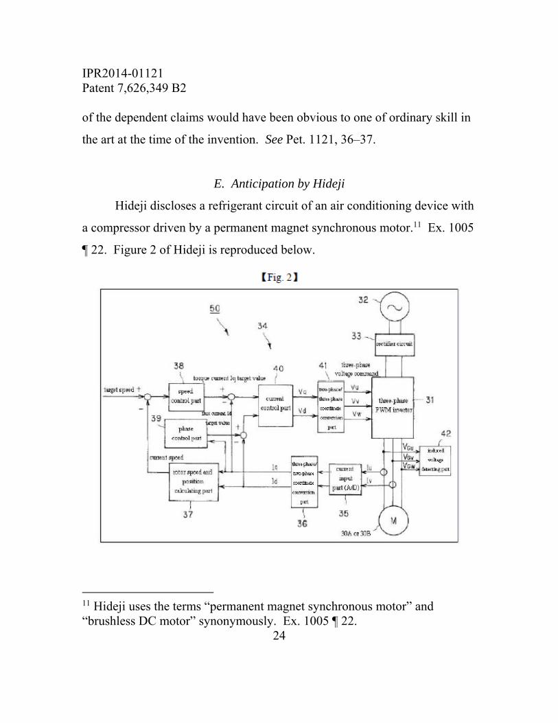
Hideji discloses a refrigerant circuit of an air conditioning device with
a compressor driven by a permanent magnet synchronous motor.11 Ex. 1005
¶ 22. Figure 2 of Hideji is reproduced below.
11 Hideji uses the terms “permanent magnet synchronous motor” and “brushless DC motor” synonymously. Ex. 1005 ¶ 22.
IPR2014-01121 Patent 7,626,349 B2
25
Figure 2 is a block diagram of a driving device for a permanent magnet
synchronous motor. Id. ¶ 28. Driving device 50 includes three-phase pulse-
width modulation (“PWM”) inverter 31, alternating-current power supply
32, rectifier circuit 33, and control device 34. Id. ¶ 30. The control device
includes power input part 35, three-phase/two-phase coordinate conversion
part 36, rotor speed and position calculating part 37, speed control part 38,
phase control part 39, current control part 40, two-phase/three-phase
coordinate conversion part 41, and induced voltage detecting part 42. Id.
¶ 32. Two-phase/three-phase coordinate conversion part 41 outputs pulse-
modulated sinusoidal voltage commands Vu, Vv, and Vw to a switching
element of the three-phase PWM inverter, thereby providing quasi-
sinusoidal three-phase alternating current to the motor. Id. ¶ 33. Three-
phase/two-phase coordinate conversion part 36 converts coordinates of two-
phase alternating current Iu and Iv introduced by current input part 35 to a
revolving coordinate system on the rotor of the motor, and calculates flux
current Id (d axis current) and torque current Iq (Q axis current). Id. ¶ 35.
Petitioner adequately identifies the “system controller,” “motor
controller,” “blower” or “air-moving component,” and “permanent magnet
motor,” recited in different combinations in independent claims 1, 16, and
19, with reference to the above structures disclosed by Hideji. Pet. 762, 12–
19, 32–44. Petitioner also identifies sufficient structure of Hideji’s brushless
DC motor that includes stator and rotor components, i.e., stationary and
rotatable assemblies with a shaft coupled to the air-moving component or
IPR2014-01121 Patent 7,626,349 B2
26
blower, as recited in the independent claims. Id. at 17–19. Petitioner’s
analysis is supported with testimony by Dr. Ehsani. Ex. 1009.
With respect to the limitations requiring “performing sinewave
commutation, using independent values of Q and d axis currents, in response
to one or more control signals received from the system controller to
produce continuous phase currents in the permanent magnet motor for
driving the air-moving component,” recited in each of independent claims 1,
16, and 19, Petitioner observes that Figure 2 of Hideji illustrates that three-
phase/two-phase coordinate conversion part 36 outputs separate values for Iq
and Id, i.e., the Q and d axis currents.12 Pet. 762, 23–24. Hideji discloses
that
[t]he three-phase/two-phase coordinate conversion part 36 converts the coordinates of the alternating current Iu and Iv introduced by the current input part 35 to a revolving coordination system (d-q coordination system) on the rotor of the brushless DC motor 30A, and calculates flux current Id (d-axis current) and torque current Iq (q-axis current).
Ex. 1005 ¶ 35. Petitioner reasons that such transformation results in
separate, independent values of Q and d axis currents determined from
control signals received from the system controller. Pet. 762, 23. Petitioner
supports this reasoning with testimony by Dr. Ehsani. Ex. 1009 ¶ 38.
12 We note that the labels “Iq” and “Id” output from part 36 of Hideji are identified directly as such in the original Japanese reference. Ex. 1003, 8.
IPR2014-01121 Patent 7,626,349 B2
27
Patent Owner responds that “[t]aken in context, the independent Q
and d axis current must necessarily be the Q and d axis currents the motor
controller calculates are required to satisfy the system controller demand and
that are used to set or produce the continuous phase sine wave commutated
currents for the motor.” Paper 72, 6. In light of our construction of “using
independent values of Q and d axis currents,” we disagree with this position.
In particular, Patent Owner’s argument that the structure identified by
Petitioner “at best, represents the instantaneous measured current values of Iq
and Id” and “is not the demanded value of Iq and Id developed by the motor
controller,” id., is unpersuasive. For the reasons expressed above, we
construe the claim limitation as requiring the use of actual Q and d axis
currents that are developed independently of each other.
Patent Owner further argues that, if Hideji were to anticipate, “it must
show that independently derived Iq and Id values are fed into the current
control part 40.” Id. at 10. Patent Owner observes that, in this context,
Hideji explicitly describes a dependence on “the Q axis current and d axis
current”:
The phase control part 39 identifies the state of a load by introducing the torque current Iq in direct proportion to the change of the load acting on the brushless DC motor 30A, to generate a flux current Id target value corresponding to the state of the load. Specifically, by introducing the torque current Iq in direct proportion to the increase of the load acting on the brushless DC motor 30A, the flux current Id target value is reduced on the basis of the following formula. In addition, in the following formula, k is a positive constant.
IPR2014-01121 Patent 7,626,349 B2
28
The flux current Id target value is equal to k×Iq2. By
reducing the flux current Id target value, the flux voltage Vd output by the after-mentioned current control part 40 is reduced, the phases of the voltage commands Vu, Vv and Vw output by the two-phase/three-phase coordinate conversion part 41 are advanced, and the phases of the voltage commands Vu, Vv and Vw delayed due to the increase of the load are restored.
Ex. 1005 ¶¶ 38–39. This argument obscures the fact that the expression in
paragraph 39 of Hideji relates the Id target value (equivalent to the demand d
axis current value) to the actual Q axis current value Iq, a fact confirmed by
both parties at the oral hearing. Tr. 15:14–16:4, 33:7–16. Hideji’s
disclosure of a proportionality of the demand d axis current and the square of
the actual Q axis current is irrelevant in light of our construction of “using
independent values of Q and d axis currents.”
We conclude that Petitioner has demonstrated, by a preponderance of
the evidence, that independent claims 1, 16, and 19 are anticipated by Hideji.
With respect to dependent claims 2, 3, 8, 9, and 12, we also conclude
that Petitioner has demonstrated that they are anticipated by Hideji.
Petitioner identifies disclosures in Hideji that correspond to the limitations in
each of these claims, identifications that are not contested by Patent Owner,
and we agree with those identifications. See Pet. 762, 27–32.
F. Motion to Amend
Contingent upon respective Board determinations that original
independent claims 1, 16, and 19 are unpatentable, Patent Owner moves to
IPR2014-01121 Patent 7,626,349 B2
29
amend those claims by substituting proposed claims 21–23. Paper 73, 6.
The proposed amendments are similar for each of the independent claims,
reciting the use of “vector control” having independent values of Q and d
axis currents, “wherein the control signals received from the system
controller are at least one member selected from the group consisting of
demanded torque, demanded speed, and demanded airflow and wherein
vector control of the motor controller enables substantially no interaction
between the motor controller and an airflow control loop of the system.” Id.
at 1–3. Patent Owner asserts that its conditional amendments “add[]
limitations to those claims that further define and narrow the scope of the
claimed invention.” Id. at 7. Patent Owner provides charts on pages 7–9 of
the Motion to Amend identifying support for existing claims limitations and
for its conditional amendments. The identified support for existing claim
limitations includes, inter alia, Figure 8 of the ’349 patent and Exhibit 3001,
i.e. the ’379 patent, which is incorporated by reference into the ’349 patent.
Id. at 7–9; Ex. 1001, col. 4, ll. 23–29.
In our Order memorializing the conference call with the parties
regarding the Motion to Amend, we directed the parties to Idle Free Sys.,
Inc. v. Bergstrom, Inc., Case IPR2012-00027 (PTAB June 11, 2013) (Paper
26) (informative), and MasterImage 3D, Inc. v. RealD Inc., Case IPR2015-
00040 (PTAB July 15, 2015) (Paper 42), for “[g]uidance regarding the
mechanics and substance of motions to amend.” Paper 71, 2. As the
moving party, Patent Owner bears the burden of establishing that it is
IPR2014-01121 Patent 7,626,349 B2
30
entitled to the relief—namely, addition of the proposed claims to the patent.
37 C.F.R. § 42.20(c). To satisfy that burden, Patent Owner must meet the
requirements of 37 C.F.R. § 42.121 and demonstrate the patentability of the
proposed substitute claims. Idle Free, Paper 26, at 6–10; see also Microsoft
Corp. v. Proxyconn, Inc., 789 F.3d 1292, 1308 (Fed. Cir. 2015) (“Assuming
an amendment is appropriately responsive to the grounds of unpatentability
involved in the trial, the patentee must still go on to show that it is entitled to
its substitute claim.”).
A component of Patent Owner’s burden includes the need “to show
patentable distinction over the prior art of record and also prior art known”
to Patent Owner. Idle Free, Paper 26, at 7. The Board has held that “prior
art of record” refers to material art in the prosecution history of the patent,
material art of record in the current proceeding before the Board, and
material art of record in any other proceeding before the Office involving the
patent. See MasterImage 3D, Paper 42, at 2. To that end, Patent Owner
discusses Bessler, Kocybik, and Hideji, and combinations of the three, in its
motion. Paper 73, 15–21. But Patent Owner does not discuss the ’379
patent, nor does it discuss U.S. Patent Nos. 6,326,750, 6,756,757, or
7,208,895, each of which is also incorporated by reference into the ’349
patent. See Ex. 1001, col. 4, ll. 23–29. Each of these references also
appears on the face of the ’349 patent as having been cited during
prosecution of the ’349 patent. Id. at [56].
IPR2014-01121 Patent 7,626,349 B2
31
Patent Owner does not challenge Petitioner’s contention that each of
these references is prior art to the ’349 patent. See Paper 77, 14–16. The
omission of these references from Patent Owner’s analysis is significant. As
we note above, the Specification of the ’349 patent provides sparse details of
how vector control is achieved in the context of the claimed invention—
whether as originally claimed or as proposed by the conditional
amendments. The drawing on which the patentee relied for adding
limitations related to vector control during prosecution is very similar to
Figures 2 and 3 of the ’379 patent; indeed, it is substantially identical to
those drawings in those respects that relate to vector control. As such, we
find at least the ’379 patent to be material prior art of record. Patent Owner
addresses the disclosure of the ’379 patent in its Reply to Petitioner’s
Opposition to Patent Owner’s Motion to Amend. Paper 80, 8–10.
When questioned at the oral hearing regarding its failure to address
the ’379 patent and other patents incorporated by reference into the ’349
patent in its Motion to Amend, Patent Owner responded that “we have to
make judgments about what we think is the closest prior art given the page
limitations that are imposed upon us.” Tr. 63:13–25. Yet Patent Owner
used less than 21 of the 25 pages permitted for motions to amend, leaving an
unused portion that exceeds the space it devotes to addressing the ’379
patent in its Reply to Petitioner’s Opposition to Patent Owner’s Motion to
Amend. See 37 C.F.R. § 42.24(a)(1)(vi).
IPR2014-01121 Patent 7,626,349 B2
32
With respect to the proposed additional limitations, Patent Owner’s
expert, Dr. Blank, testified that the ’379 patent discloses “vector control.”
Ex. 1043, 14:14–15:14. The “speed loop controller” that appears in Figure 8
of the ’349 patent (identified by the Board as element 815 supra) also
appears in Figure 3 of the ’379 patent, interfacing with elements of the
vector control scheme in the same way. Dr. Blank testified that the “airflow
control loop” proposed to be added to the claims would be recognized as
included in the “speed loop controller.” Id. at 80:8–82:4 (“So it’s not
explicit, but it’s in there.”). According to Dr. Blank, there would be
substantially no motor controller interaction with such an airflow loop
controller. Id. at 82:5–83:3. Furthermore, Dr. Blank testified that column 6,
lines 1–7 of the ’379 patent would teach a person of ordinary skill how to
generate independent Q and d axis currents. Id. at 46:13–49:1.
Thus, we are not persuaded that Patent Owner’s proposed
amendments adequately distinguish from the disclosure of the ’379 patent.
Accordingly, we deny Patent Owner’s Motion to Amend.
F. Motions for Observation
Patent Owner filed three (sealed) motions for observation on the
cross-examination of three witnesses of Petitioner (Papers 46–49).
Petitioner responded with three separately filed Responses (Papers 59–61).
The Scheduling Order provides for a single motion for observation on
cross-examination from either party, and a single response from the
IPR2014-01121 Patent 7,626,349 B2
33
opposing party, each of which is limited to 15 pages. See Paper 21, 5; 37
C.F.R. §§ 42.24(a)(1)(v), 42.24(b)(3). As such, we have considered only the
first 15 pages filed by each party in rendering our Decision. See Papers 46,
59, 60; Paper 61, 1.
III. ORDER
In consideration of the foregoing, it is hereby:
ORDERED that, based on a preponderance of the evidence, claims 1–
3, 8, 9, 12, 16, and 19 of U.S. Patent No. 7,626,349 B2 are held to be
unpatentable;
FURTHER ORDERED that Petitioner’s Motion to Exclude portions
of Exhibit 2003 and the entirety of Exhibits 2010, 2011, and 2018–2025 is
dismissed;
FURTHER ORDERED that Patent Owner’s Motion to Exclude
portions of Exhibit 1020 and the entirety of Exhibits 1034 and 1035 is
dismissed;
FURTHER ORDERED that Patent Owner’s Motion to Amend is
denied; and
FURTHER ORDERED that, because this is a final written decision,
parties to this proceeding seeking judicial review of our decision must
comply with the notice and service requirements of 37 C.F.R. § 90.2.

IPR2014-01121 Patent 7,626,349 B2
34
PETITIONER
Steven Meyer [email protected] Charles Baker [email protected]
PATENT OWNER
Scott Brown [email protected] Matthew Walters [email protected]