Embed Size (px)
Citation preview

UNITED STATES NUCLEAR REGULATORY COMMISSION
WASHINGTON, D.C. 20555-0001
May 27, 2009
Mr. J. R. Morris Site Vice President Catawba Nuclear Station Duke Energy Carolinas, LLC 4800 Concord Road York, SC 29745
SUBJECT: CATAWBA NUCLEAR STATION, UNITS 1 AND 2, RELIEF 06-CN-003 FOR USE OF POLYETHYLENE MATERIAL IN BURIED SERVICE WATER PIPING (TAC NOS. ME0234 AND ME0235)
Dear Mr. Morris:
By letter dated October 26, 2006, as supplemented by letters dated June 21, 2007, March 13, 2008, May 29, 2008, October 21, 2008, and November 20, 2008, Duke Energy Carolinas LLC (the licensee), submitted Relief Request No. 06-CN-003, which proposed an alternative to certain requirements of the American Society of Mechanical Engineers (ASME), Boiler and Pressure Vessel Code (Code), Section XI, 1998 Edition through the 2000 Addenda requirement pertaining to the use of high-density polyethylene (HDPE) pipe in lieu of the ASME Code requirement, IWA-4221(b), carbon steel piping for the third 10-year inservice inspection (lSI) intervals at Catawba Nuclear Station, Units 1 and 2 (Catawba 1 and 2).
The Nuclear Regulatory Commission (NRC) staff reviewed the licensee's submittal and, based on the information provided, and based on the regulatory commitments made by the licensee as described in the enclosed safety evaluation, the NRC staff concludes that the use of HDPE pipe for ASME Code Class 3, 12-inch nominal diameter supply buried piping lines 1A, 1B, 2A, and 2B, in addition to the buried return piping lines 1A, 1B, 2A, and 2B to and from the diesel generator jacket water coolers, as described in the submittal, as supplemented by letters dated June 21, 2007, March 13, 2008, May 29,2008, October 21,2008, and November 20,2008, will provide an acceptable level of quality and safety. Prior to submitting the fourth 10-year lSI interval plan for Catawba 1 and 2, the licensee will submit information obtained from the testing programs currently underway to the NRC in accordance with the following regulatory commitments: (i) if the information supports operation of the HDPE piping using PE 4710 material for the remainder of the plant life, this information will be submitted to the NRC for information only, and (ii) if the results from the testing program do not support the operation using HDPE piping with PE 4710 material for the remainder of the plant life, this information will be submitted to the NRC staff as a part of a subsequent request for an alternative to the fourth 10-year lSI Interval.
Therefore, pursuant to Title 10 of the Code of Federal Regulations (10 CFR), Part 50, Section 50.55a(a)(3)(i), the NRC staff authorizes the inspection, testing, and quality assurance aspects of the proposed alternative to ASME Code, Section XI, IWA-4221 (b) reqUirements, for Catawba 1 and 2 for the third 10-year lSI intervals.
J. Morris - 2
All other requirements of ASME Code, Section XI for which relief has not been specifically requested remain applicable, including third-party review by the Authorized Nuclear Inservice Inspector.
If you have any questions, please call me at 301-415-2911.
Sincerely,
'»{~ /J\( Melanie Wong, Chief Plant Licensing Branch 11-1 Division of Operating Reactor Licensing Office of Nuclear Reactor Regulation
Docket Nos. 50-413 and 50-414
Enclosure: Safety Evaluation
cc w/encl: Distribution via Listserv

UNITED STATES NUCLEAR REGULATORY COMMISSION
WASHINGTON, D.C. 20555-0001
SAFETY EVALUATION BY THE OFFICE OF NUCLEAR REACTOR REGULATION
OF THIRD 10-YEAR INTERVAL INSERVICE INSPECTION
RELIEF NO. 06-CN-003
DUKE ENERGY CAROLINAS, LLC
CATAWBA NUCLEAR STATION, UNITS 1 AND 2
DOCKET NOS. 50-413 AND 50-414
1.0 INTRODUCTION
By letter dated October 26, 2006, (Agencywide Documents Access and Management System (ADAMS) Accession No. ML063120215), as supplemented by letters dated June 21, 2007 (ADAMS Accession No. ML091350309), March 13, 2008 (ADAMS Accession No. ML080790104), May 29,2008 (ADAMS Accession No. ML081550652), October 21,2008 (ADAMS Accession No. ML083010087), and November 20, 2008 (ADAMS Accession No. ML090260120), Duke Energy Carolinas, LLC (the licensee), submitted Request for Relief 06-CN-003, which proposed an alternative to certain requirements of the American Society of Mechanical Engineers (ASME), Boiler and Pressure Vessel Code (Code), Section XI, 1998 Edition through the 2000 Addenda, requirement pertaining to the use of high-density polyethylene (HDPE) pipe in lieu of the ASME Code requirement, IWA-4221 (b), carbon steel piping for the third 10-year inservice inspection (lSI) intervals at Catawba Nuclear Station, Units 1 and 2 (Catawba 1 and 2). There are a total of 8 lines for which the licensee is seeking approval for the use of HDPE pipe. These are the 12-inch buried supply and return lines 1A, 'I B, 2A and 2B to the diesel generator jacket water coolers. The third 1O-year interval for Catawba 1 began on June 29, 2005, and ends June 29, 2015. The third 1O-year interval for Catawba 2 began on October 15, 2005, and ends August 19, 2016.
2.0 BACKGROUND
Both corrosion and fouling problems have occurred in the nuclear service water (RN) system piping at Catawba 1 and 2. The RN system piping was originally designed using carbon steel with our internal coating or lining. The licensee stated that HDPE piping offers advantages in corrosion protection over corrosion protection provided by a coating or liner. The licensee also indicated that the primary advantage in using HDPE pipe versus carbon steel pipe materials is its resistance to fouling, corrosion, and microbiologically induced corrosion (MIC). HDPE piping is also not susceptible to galvanic attack. The licensee further stated that portions of the Catawba 1 and 2 RN piping replaced with corrosion resistant steel have experienced accelerated microbiological attack and developed pinhole leaks during service. In contrast, the licensee stated that some 20,000 linear feet of the Catawba 1 and 2 non safety-related service water system HDPE piping of sizes up to 32 inches continues to perform well, with excellent service history since 1998. The licensee included additional supporting information about the
Enclosure

- 2
successful performance of a limited amount of HOPE piping in the above ground safety-related ASME Code, Section III, Class 3, service water piping at British Energy's Sizewell B plant. Sizewell B is the first plant in the world to install HOPE piping in nuclear safety-related systems. The licensee also stated that the resistance of the HOPE pipe to corrosion and fouling (tubercle formation and MIC) ensures long-term reliability from a structural integrity and flow standpoint.
3.0 REGULATORY EVALUATION
In accordance with Title 10 of the Code of Federal Regulations (10 CFR), Part 50, Section 50.55a(g)(4), ASME Code Class 1,2, and 3 components must meet the requirements set forth in ASME Code, Section XI, "Rules for Inservice Inspection of Nuclear Power Plant Components," to the extent practical within the limitations of design, geometry, and materials of construction of the components. The regulations require that all inservice examinations and system pressure tests conducted during the first 10-year interval, and subsequent intervals, comply with the requirements in the latest edition and addenda of ASME Code, Section XI, incorporated by reference in 10 CFR 50.55a(b) on the date 12 months prior to the start of the 1O-year interval. For Catawba 1 and 2, the code of record for the third 1O-year lSI intervals is the 1998 Edition through the 2000 Addenda, of Section XI of the ASME Code.
Alternatives to requirements may be authorized by the Nuclear Regulatory Commission (NRC) pursuant to 10 CFR 50.55a(a)(3)(i), or 10 CFR 50.55a(a)(3)(ii). In proposing alternatives or requesting relief, the licensee must demonstrate that the proposed alternatives provide an acceptable level of safety or that compliance would result in hardship or unusual difficulty without a compensating increase in the level of quality and safety. Pursuant to 10 CFR 50.55a(g)(4)(iv), lSI items may meet the requirements set forth in subsequent editions and addenda of the ASME Code that are incorporated by reference in 10 CFR 50.55a(b), subject to the limitations and modifications listed therein, and subject to NRC staff's approval. Portions of editions and addenda may be used provided that related requirements of the respective editions and addenda are also met.
Additionally, Regulatory Guide (RG) 1.84 provides a listing of the Code Cases which are currently acceptable by the NRC staff. Code Case N-755 regarding the use of Polyethylene (PE) plastic pipe for Section III, Division 1, Construction and Section XI Repair and Replacement Activities, was recently approved by ASME. However, the Code Case has not been accepted by the NRC staff since the acceptability of PE piping is dependent on current, on-going, and future testing activities.
4.0 DESCRIPTION OF PROPOSED ALTERNATIVE AND BASIS
4.1 Affected Components
The affected components include ASME Code Class 3, 12-inch nominal diameter supply and return buried piping to and from the diesel generator jacket water coolers.
4.2 Applicable Code Requirements
ASME Code, Section XI, IWA-4221 (b) requires that an item to be used for repair/replacement activities shall meet the Construction Code specified and IWA-4221 (b)(1) which requires that

- 3
when replacing an existing item, the new item shall meet the Construction Code to which the original item was constructed. The Construction Code of record for buried ASME Code, Section XI, Class 3, piping is the ASME Code, Section III, Subsection NO, 1974 Edition through Summer 1974 Addenda.
4.3 Proposed Alternative
Pursuant to 10 CFR 50.55a(a)(3)(i), in lieu of Section XI, IWA-4221(b)(1) the licensee requested approval to replace steel piping with HOPE piping. In the letters dated October 26, 2006, June 21, 2007, and March 13, 2008, the licensee provided the rules that will be used in lieu of the original Construction Code for the design, fabrication, installation, examination, and testing of the HOPE piping.
4.4 Licensee Basis for the Alternative
The Construction Code and later editions and addenda of the Construction Code do not provide rules for the design, fabrication, installation, examination, and testing of HOPE piping. The primary advantage with using HOPE piping versus other carbon steel piping is its resistance to fouling, corrosion, and MIC. The HOPE piping does not experience fouling or corrosion and is not susceptible to galvanic or microbiological attack. The HOPE piping's resistance to corrosion and fouling ensures long-term reliability from a structural integrity and liquid flow standpoint. The 20,000 linear feet of HOPE piping already in service in the Catawba 1 and 2 nonsafetyrelated service water system of sizes up to 32 inches National Piping Standard (NPS) has demonstrated the potential acceptability of polyethylene material for service.
At Catawba 1 and 2, the low-pressure service water (RL) system supplies cooling water to the containment chilled water (YV) system chiller condensers. Prior to replacing the carbon steel piping with HOPE piping, monitoring of the RL flow control valve position and YV condenser pressures showed the valves to be fully open during the summer months and condenser pressures up to 150 pounds per square inch gage (psig), which is a few psig away from the system trip set point. After replacing the carbon steel with polyethylene piping and operating for two cycles, the control valves have been operating at less than 50 percent open and the condenser pressures have been running around 125 psig during the summer months. This is a clear indication that the use of HDPE piping will result in improved system performance and enhanced system reliability. Since the installation of HOPE piping at Catawba 1 and 2 in nonsafety-related applications, there has not been a failure or leakage of the HOPE piping or joints.
5.0 TECHNICAL EVALUATION
The ASME Code, Section III, Subsection NO, 1974 Edition including the Summer 1974 Addendum, w~lich is the Construction Code for Catawba 1 and 2, as well as later editions and addenda, do not provide rules for the design, fabrication, installation, examination, and testing of piping constructed using polyethylene material. The NRC staff reviewed the licensee's supporting technical documentation for the use of HOPE piping at Catawba 1 and 2. The NRC staff's evaluation is presented below.

-4
5.1 Acceptance of HOPE Material PE 4710 for Class 3 Piping
The evaluations performed by the licensee were based on the properties of polyethylene (PE) 3408 material. The NRC staff requested additional information concerning clarification on whether the PE material is PE 3408 or PE 4710 that would be used to replace existing carbon steel piping. The licensee stated that it intends to use the HOPE PE 4710 material to replace the steel piping in ASME Code, Section III, Class 3, nuclear safety-related buried piping to and from the diesel generator jacket water coolers. The licensee submitted additional documentation showing the comparison of the physical and mechanical properties of PE 3408 and PE 4710 materials, concluding that the differences are not very significant, and that PE 471 ahas greater resistance to slow crack growth. The licensee stated that the PE 4710 material properties meet or exceed the PE 3408 material properties. The sample analyses presented by the licensee justifying the use of HOPE piping are based on the PE 3408 properties. The licensee also stated that the sample analyses will be developed into a design calculation during project implementation, and that the analyses will be revised to reference only the PE 4710 material. The completed as-designed calculations for all eight (supply and return) lines, provided by the licensee in its letter dated November 20,2008, adequately address the design properties of the PE 4710 material. Based on its review, the NRC staff finds this approach acceptable because the licensee's analysis methodology provides an adequate means to demonstrate the structural integrity of the HOPE piping to be used in the proposed relief request.
5.2 HOPE Flaw Depth Allowance
During its review, the NRC staff raised concerns on the issue of flaws of 1a-percent wall thickness and premature leaks or failures in the HOPE piping of the PE 4710 material due to slow crack growth. The NRC staff requested additional supporting test data. The licensee stated that there is insufficient test data to support the allowance of scratches with a depth of up to 10 percent of the wall thickness for extended service life for all pipe sizes and design temperatures. Testing is being planned by the industry but will not be completed in a time frame to support the Catawba 1 and 2 schedule for piping replacement. Based on the examination of the existing test data available to date, the licensee made modifications for the allowance on scratch depth as follows: (a) for piping less than or equal to 4 inches with a standard dimension ratio (SOR) greater than 11, scratch depth allowance of no more than 10 percent of the nominal wall thickness is permitted, (b) for piping less than or equal to 4 inches with an SOR less than 11, scratch depth allowance of the smaller of either 10 percent of the nominal wall thickness or 0.041 inches is permitted, (c) for piping greater than 4 inches, scratch depth allowance of the smaller of either 10 percent of the nominal wall thickness or 0.041 inches is permitted. The licensee further stated that any unacceptable scratches or damage to the HOPE piping will be cut out and replaced or scratches removed by blending smoothly. Based on an independent analysis, the NRC staff finds the licensee's scratch depth analysis and flaw depth limits acceptable.
The licensee provided information with regard to the unacceptability of the inclusions, and cold fusion in HOPE piping fused joints. The licensee has taken several measures to ensure a high confidence that flaws are not incorporated into the fused joints. The SE measures include: fusion process controls, requirements on essential joining parameters (fusion temperature, pressure, and time of pressure application), personnel training and qualifications, procedural

- 5
requirements to avoid contamination or moisture introduction into the joint, visual inspection of the bead profile, and hydrostatic testing. Based on the above, the NRC staff finds the measures taken by the licensee to prevent unacceptable inclusions and cold fusion in HOPE piping fused joints acceptable.
5.3 HOPE Piping Flange Joint Interface and Fusion Joint Offset
In response to a request for additional information concerning the evaluation of the flanged joint interface between the metallic piping and polyethylene piping, the licensee stated that as a part of the ongoing Electric Power Research Institute's (EPRl's) test program, the HOPE flanges are tested until they leak. The results of these tests are summarized in the Interim EPRI Report 1014902, "Fatigue and Capacity Testing of High Oensity Polyethylene Pipe MateriaL" The report shows that with adequate bolt preload, the flange's capacity is greater than that of the attached pipe. If stresses in the fusion butt joints connecting the flange adapter to the pipe meet the design procedure limits, then the moment loading transmitted to the flanged joint will be below that which is necessary to cause flange leakage. Based on this additional information provided by the licensee, the NRC staff finds that specific analysis and design requirements for the HOPE flange-to-steel flange connection is not required.
The licensee stated that the strain limits for the HOPE piping are based on the standard manufacturers' HOPE pipe curvature. The allowable pipe bending radius of greater than 30 outside diameters (OOs) is based on the licensee's experience with the installation of HOPE piping, and the allowable ring deflection values listed in the Plastic Pipe Institute (PPI) Handbook for HOPE piping. The licensee also stated that the long-term and short-term Poisson's ratio values of 0.35 and 0.45, respectively, for HOPE material are reasonable values based on industry recommendations. In addition, the NRC staff raised concerns about offset or surface mismatch in a fused joint. The licensee performed a finite element analysis to justify a 1O-percent offset or mismatch. The NRC staff reviewed the analysis and found that the element size was the same throughout the analysis. The NRC staff requested additional justification of the 10-percent offset or mismatch. The licensee performed an additional finite element analysis with finer size elements. This analysis demonstrated the acceptability of a 10-percent mismatch or offset in the fused joints. Based on its review of the licensee's analyses, the NRC staff finds the analyses and supporting justification acceptable.
5.4 Stress Intensification Factor Values for Fusion Butt Joints and Miter Bends
The NRC staff requested additional information concerning the stress intensification factor (SIF or i) values for fusion butt joints and miter bends versus SIF values used by the licensee in justifying the proposed alternative. The licensee used SIF values of 1 for the fusion butt weld joint stress and 2 for mitered elbow stress. SIF values of 1.0 for fusion butt joints and 2.0 for miter bends are recommended in the Code Case for the use of HOPE piping. At the time the licensee submitted the relief request, EPRI had not completed the testing of HOPE piping to determine the appropriated SIF valves. The NRC staff considered that higher SIF values are reasonable for use until the test results were available for HOPE piping. The NRC staff performed an independent calculation of the stresses in buried HOPE piping using higher SIF values of 2.0 for a fusion butt joint and 3.0 for a miter bend. Based on the SE calculations, the NRC staff concludes that the re-computed stresses using higher SIF values for the fusion butt joints and miter bends are acceptable, as shown in the table on the following page. Stresses

- 6
calculated by the NRC staff were higher than those calculated by the licensee; however, they are below the allowable stresses. EPRI has completed final SIF testing for the HOPE piping. The test results are documented in EPRI Report 1015062, "Fatigue and Capacity Testing of High-Density PE Pipe and Pipe Components Fabricated from PE 4710." Markl's approach to design was used to assign an SIF of 1 for straight pipe butt fused joints and SIFs for other fittings are then determined based on the test data. The SIF of 1 for a butt fused joint was qualified by testing and this data was used to construct fatigue curves in the report. The SIF of 2 for five-segment mitered elbows was determined from fatigue testing of 12-inch mitered elbows with SIFs of 1.83 and 1.84. The data from this final EPRI report substantiates the SIFs that were used by the licensee to justify the proposed alternative. Based on the above, the NRC staff finds the SIF values used by the licensee adequate for HOPE piping with PE 4710 material.
In addition, the NRC staff requested additional information concerning the licensee's approach of combining certain load cases by square root sum of squares (SRSS), rather than absolute sum, for seismic results for buried pipe. The licensee stated in the response to the request for additional information (RAI) that the above ground steel piping and the buried piping can be considered as two separate spectral groups and can be combined by SRSS in accordance with the guidance in RG 1.92, "Combining Modal Responses and Spatial Components in Seismic Response Analysis," Appendix N of Section III. The NRC staff finds that the licensee's methodology provided in the RAI response sent by letter dated November 20, 2008, to be consistent with the guidance provided in RG 1.92 and, therefore, acceptable.
The NRC staff also requested additional information from the licensee regarding the methodology, assumptions, input parameters, and allowable limits used by the licensee to analyze supply lines 1Band 2B and return lines 1A, 1B, 2A, and 2B for the diesel generator water jacket coolers. The licensee had previously submitted this information for supply lines 1A and 2A. In its November 20, 2008, response to the NRC staff's request, the licensee provided detailed calculations regarding the analysis of each line for which relief was requested. These calculations confirm that the same methodology, previously reviewed and accepted by the NRC staff for use in the 1A and 2A supply lines, was utilized in analyzing the two remaining supply lines and four return lines. Therefore, the NRC staff finds the licensee's results of the analyses acceptable as they meet the allowable values.

- 7
Fusion Butt Weld Stress Mitered Elbow Stress Allowable Stressi=1 i=2 i=2 i=3
Licensee's Stress NRC Staff's Stress Licensee's Stress NRC Staff's Stress Calculation Calculation Calculation Calculation
Diesel Generator Building Supply Line 1A Thermal 279 psi 407 psi 503 psi 698 psi 1100 psi Expansion Load Seismic Load 241 psi 376 psi 466 psi 656 psi 1100 psi
Diesel Generator Building Supply Line 2A Thermal 286 psi 391 psi 434 psi 614 psi 1100 psi Expansion Load Seismic Load 244 psi 364 psi 405 psi 580 psi 1100 psi
Diesel Generator Building Supply Line 1B
Thermal 213 psi 265 psi 342 psi 473 psi 1100 psi Expansion Load Seismic Load 253 psi 312 psi 467 psi 656 psi 1100 psi
Diesel Generator Building Supply Line 2B
Thermal 288 psi 392 psi 432 psi 611 psi 1100 psi Expansion Load Seismic Load 190 psi 255 psi 404 psi 577 psi 1100 psi
Diesel Generator Building Return Line 1A
Thermal 275 psi 340 psi 473 psi 654 psi 1100 psi Expansion Load Seismic Load 240 psi 377 psi 471 psi 663 psi 1100 psi
Diesel Generator Building Return Line 2A
Thermal 273 psi 359 psi 402 psi 566 psi 1100 psi Expansion Load Seismic Load 244 psi 363 psi 403 psi 577 psi 1100 psi
Diesel Generator Building Return Line 1B
Thermal 336 psi 447 psi 471 psi 651 psi 1100 psi Expansion Load Seismic Load 287 psi 383 psi 467 psi 656 psi 1100 psi
Diesel Generator Building Return Line 2B
Thermal 274 psi 360 psi 403 psi 568 psi 1100 psi Expansion Load Seismic Load 245 psi 365 psi 405 psi 578 psi 1100 psi
..Note: For fusion butt weld stresses, straight piping section stresses were used.
5.5 HDPE Piping Elastic Modulus
The NRC staff requested additional information concerning clarification on whether an adjustment due to an elastic modulus change is need!~d for the 1100 pounds per square inch (psi) allowable alternating stress amplitude used for the buried HDPE piping for thermal expansion stresses and seismic stresses evaluated using the equivalent thermal approach. The licensee provided clarification and rationale by statin!;j; that the fatigue tests reported in EPRI Report 1014902 were displacement (strain) controlled tests and the resulting stress capacities
- 8
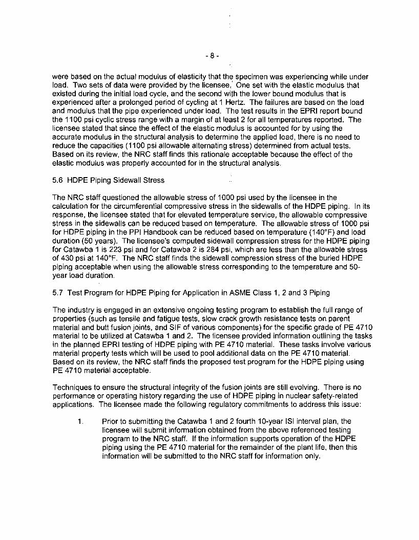
were based on the actual modulus of elasticity that the specimen was experiencing while under load. Two sets of data were provided by the licensee,' One set with the elastic modulus that existed during the initial load cycle, and the second with the lower bound modulus that is experienced after a prolonged period of cycling at 1 Hertz. The failures are based on the load and modulus that the pipe experienced under load. The test results in the EPRI report bound the 1100 psi cyclic stress range with a margin of at least 2 for all temperatures reported. The licensee stated that since the effect of the elastic modulus is accounted for by using the accurate modulus in the structural analysis to determine the applied load, there is no need to reduce the capacities (1100 psi allowable alternating stress) determined from actual tests. Based on its review, the NRC staff finds this rationale acceptable because the effect of the elastic modulus was properly accounted for in the structural analysis.
5.6 HOPE Piping Sidewall Stress
The NRC staff questioned the allowable stress of 1000 psi used by the licensee in the calculation for the circumferential compressive stress in the sidewalls of the HOPE piping. In its response, the licensee stated that for elevated temperature service, the allowable compressive stress in the sidewalls can be reduced based on temperature. The allowable stress of 1000 psi for HOPE piping in the PPI Handbook can be reduced based on temperature (140°F) and load duration (50 years). The licensee's computed sidewall compression stress for the HOPE piping for Catawba 1 is 223 psi and for Catawba 2 is 284 psi, which are less than the allowable stress of 430 psi at 140°F. The NRC staff finds the sidewall compression stress of the buried HOPE piping acceptable when using the allowable stress corresponding to the temperature and 50year load duration.
5.7 Test Program for HOPE Piping for Application in ASME Class 1,2 and 3 Piping
The industry is engaged in an extensive ongoing testing program to establish the full range of properties (such as tensile and fatigue tests, slow crack growth resistance tests on parent material and butt fusion joints, and SIF of various components) for the specific grade of PE 4710 material to be utilized at Catawba 1 and 2. The licensee provided information outlining the tasks in the planned EPRI testing of HOPE piping with PE 4710 material. These tasks involve various material property tests which will be used to pool additional data on the PE 4710 material. Based on its review, the NRC staff finds the proposed test program for the HOPE piping using PE 4710 material acceptable.
Techniques to ensure the structural integrity of the fusion joints are still evolving. There is no performance or operating history regarding the use of HOPE piping in nuclear safety-related applications. The licensee made the following regulatory commitments to address this issue:
1. Prior to submitting the Catawba 1 and 2 fourth 10-year lSI interval plan, the licensee will submit information obtained from the above referenced testing program to the NRC staff. If the information supports operation of the HOPE piping using the PE 4710 material for the remainder of the plant life, then this information will be submitted to the !\IRC staff for information only.

- 9
2. If the results from the testing program do not support the use of HDPE piping with PE 4710 material for the remainder of the plant life, this information will be submitted to the NRC staff as a part of a subsequent request for an alternative to the fourth 1O-year lSI Interval.
5.8 Evaluation of Proposed Fabrication, Examination, and Testing
Division 1 of the ASME Code, Section III and Section XI, predominately addresses applications for metal piping and metal components. The metal piping commonly used in nuclear power plants to transport water is susceptible to corrosion, fouling, rusting, and microbiological attack. The licensee must continually maintain, repair, and replace the degraded metal. Also buried pipe creates potentially unseen hazards to the activities taking place above the pipe. To mitigate the degradation mechanisms affecting metal pipe, the nuclear power industry has selectively installed HDPE piping in nonsafety-related applications. To date, the nonsafetyrelated HDPE piping applications have been free of these degradation mechanisms. The industry's experience indicates that selected ASME Code Class 3 water carrying systems should be suitable for HDPE piping as an alternative to the current metal piping.
The licensee will autogenously fuse the HDPE pipe joints together. The methods being used to ensure joint integrity are fabrication operator qualification, visual testing personnel qualifications, procedure qualifications, destructive testing, process controls, visual examinations, and pressure testing.
The licensee has performed a 10 CFR Part 50, Appendix B, audit of its HDPE pipe and pipe fitting supplier. The audit included visual examination of the joining process and a review of the destructive testing data performed by the supplier. The licensee will be performing independent receipt inspection and testing of the purchased HDPE piping. The application of 10 CFR Part 50, Appendix B, on material suppliers is a license requirement.
5.9 Procedure Qualification
For procedure qualification, the licensee is relying on in-house destructive and nondestructive testing, and data published by the PPI, "Generic Butt Fusion Joining Procedure for Field Joining of Polyethylene Pipe, Technical Report (TR)-33/2006." The licensee's selection of essential variables is for the 12-inch nominal diameter, SDR 11, HDPE pipe. TR-33/2006 lists as essential variables time, temperature, and pressure for fused joints. TR-33/2006 provides approximate heater bead melt size based on pipe diameter (12-inch nominal diameter). The licensee performed in-house testing to validate the ranges for selected variables and will record the values of the TR-33/2006 essential variables during the fusion process. The recorded variables will be reviewed for acceptance before burying the pipe segment. If any variables deviate outside the accepted ranges, the fused joint will be removed.
For gas pipe lines, TR-33/2006 requires that fused joints satisfy 49 CFR Part 192, Section 192.283, which states that the procedure must be qualified by subjecting specimen joints made according to: (1) the burst test requirements of a sustained pressure test, minimum hydrostatic burst test or sustained static pressure test, and (2) the lateral pipe connection tests which subject the pipe and 90-degree fitting to a force until failure or a tensile test. The licensee intends on performing testing similar to 49 CFR Part 192 requirements. For the first (1 )

- 10
criterion, the licensee will subject the HOPE pipe to a system pressure test at 150 percent above design pressure. For the second (2) criterion, the licensee is using fittings with thicker walls than the pipe and subjecting pipe joints to routine impact tensile tests. The pipe joints should fail before the fitting joints fail.
The licensee's proposed alternative is specifically for 12-inch diameter, SOR 11, type PE 4710 HOPE pipe with joints made using the butt fusion process; pipe fusibility is verified at the extremes of the temperature and pressure essential variable ranges. Besides the limited application, the procedure effectiveness will be constantly checked with in-process testing, thus assuring satisfactory joints. Based on its review, the NRC staff finds the licensee's procedure, as applied, acceptable.
5.10 Fusion Operator Qualification
TR-33/2006 references 49 CFR Part 192 for fusion operator qualifications. Section 192.285(b)(2) of 49 CFR Part 192 requires that joints be ultrasonically tested or sectioned longitudinally in three locations and visually examined for voids or discontinuities on the cut surface. The licensee is using an in-process approach for satisfying this criterion by performing daily and performing random in-house impact tensile testing of joints. This testing will be performed during the entire duration of the piping system construction. The impact tensile test specimens are taken from the longitudinal direction through the fused joint. During impact tensile test specimen preparation, obvious internal defects would be exposed and detectable. Impact tensile specimens with internal defects may also display an unusual failure appearance. The visual examination of in-process test specimen will detect internal void and discontinuities. Based on its review, the NRC staff finds the qualifications for a fusion operator acceptable.
5.11 Volumetric Testing (VT)-1 HOPE Piping Qualifications
The licensee will provide a minimum of 16 hours of additional training to certify qualified VT-1 personnel for reviewing recorded fusion joining data and perform bead appearance examinations. The licensee will give VT-1 personnel hands-on-practice in operating HOPE fabrication equipment and making fused butt joints. The VT-1 personnel must successfully pass a licensee-administered performance demonstration consisting of a combination of 10 or more acceptable and unacceptable fused joints. In addition, inside surface examples of visually acceptable and unacceptable joints will be available to provide supplemental visual comparison standards for visual examinations. Personnel who successfully demonstrate their skills on representative mockups of acceptable and rejectable fused joints assure proficiency. Based on its review, the NRC staff finds the qualifications of the VT-1 testing personnel acceptable.
5.12 Hydrostatic Testing
The licensee will perform a hydrostatic test at 150 percent above the system design pressure to verify leak tightness. The piping will be examined for leakage using ASME Code, Section XI, qualified VT-2 personnel. The licensee will provide the VT-2 personnel with 4 additional hours of training on HOPE fused pipe joints. The hydrostatic test is effective in detecting existing though-wall flaws. However, because HOPE material is viscoelastic and flows over time, the hydrostatic test gives little, if any, information on embedded flaws which may grow over time.

- 11
The hydrostatic test is an effective method of validating system leak tightness at the time of testing. The NRC staff finds the hydrostatic testing that will be performed on the HDPE piping acceptable.
5.13 Volumetric Flaws
During the fusion process, the licensee will be examining the pipe ends for defects, such as foreign material, voids, and porosity. If any defects are detected, the licensee will initiate their problem investigation process. The visual examinations being performed on the bead joint should indicate gross internal joint unsoundness.
While typical volumetric flaws and internal cracks with wide opening dimensions are readily detectable with current nondestructive examination (NDE) methods, "cold fusion" flaws resulting from inadequacies in the joining process are elusive to detection. Cold fusion is unique to PE fused joints. Efforts are on-going to identify /'JDE methods that can reliability detect cold fusion. In time, improvements in vOlumetric examination methods may be capable of reliably detecting cold fusion flaws or operating flaws that might occur during plant operations.
Since volumetric examinations would provide increased confidence in piping system structural integrity, the licensee is providing access to the inside surface of the HDPE piping for future NDE examinations. Providing access to the piping system for future examinations, if needed, adds monitoring flexibility to the system. Based on its review, the NRC staff finds that the licensee has adequate monitoring controls in place to ensure the structural integrity of the piping system.
5.14 Process Control
In some instances, cold fusion can be detected from the bead appearance that is formed during the fusion process. TR-33/2006 states that the fusion beads should be approximately 2 to 2.5 times the bead height above the pipe and should be rounded and uniformly sized all around the pipe. The bead appearance is also affected by typical volumetric defects and by environmental influences. The bead appearance can provide useful information on a fused joint's internal soundness. The licensee will visually examine both the inside diameter and outside diameter bead appearance for acceptability.
A fused joint with a good appearance is an indicator but does not guarantee sound joints. The licensee provided information on fused joints made from 12-inch diameter SDR 11 HDPE pipe. The licensee varied the fusion temperatures and pressures beyond the acceptable essential variable ranges of the procedure. The results indicated that very low temperatures with high or low pressures produced visually unacceptable joints, and misaligned pipe ends produced visually unacceptable joints. Looking at the cross sections, the joints appeared to be sound; however, visual examination alone is not sufficient to detect "cold fusion." The absence of, or an insufficient, crystalline structure weakens the joint, thus making it more susceptible to failure than the pipe itself.
The licensee is using in-process destructive testing to verify fusion equipment operability and internal pipe/joint soundness. A least 10 percent of each field joint from each fusion machine will be tested during a production shift, and at least one blind random field joint will be selected

- 12
for impact tensile testing within a 4 shift period. If any weakness is detected, the licensee will remove the joints produced since the last successful impact tensile test. The in-process testing during installation of the pipe system provides an effective means for assuring joint functionality.
Although efforts are still underway to improve HOPE pipe and examination of HOPE pipe, its application may greatly improve the reliability of specific piping systems. The licensee's use of fabrication process controls, subsequent VT-1 examinations, hydrostatic testing, and random impact tensile testing provides a means for detecting flaws that may have the potential for through-wall growth. The use of HOPE pipe has the potential for improving pipe system reliability in corrosive environments that are challenging to metal pipe. Although the ASME Code does not currently provide rules for HOPE pipe applications that are acceptable to the NRC staff, the supporting information submitted by the licensee in the relief request has demonstrated to the NRC staff reasonable assurance in maintaining structural integrity of the HOPE piping. For the licensee's specified application in the submittal, the use of HOPE piping as an alternative to the ASME Code-required metal piping will provide an acceptable level of quality and safety for the length of time supported by long-term testing.
6.0 CONCLUSION
The NRC staff reviewed the licensee's submittal and supporting technical information for the proposed alternative pertaining to the use of HOPE buried pipe in nuclear safety-related piping applications. Based on the above evaluation, and the regulatory commitments made by the licensee as stated below, the NRC staff concludes that the use of HOPE pipe for ASME Code Class 3, 12-inch nominal diameter supply buried piping lines 1A, 1B, 2A, and 2B, in addition to the buried return piping lines 1A, 1B, 2A, and 2B to and from the diesel generator jacket water coolers, as described in the relief request, with the corresponding supplements, will provide an acceptable level of quality and safety. Prior to submitting the fourth 10-year lSI interval plan for Catawba 1 and 2, the licensee will submit information obtained from the testing programs currently underway to the NRC staff in accordance with the following regulatory commitments:
1. If the information supports operation of the HOPE piping using PE 4710 material for the remainder of the plant life, this information will be submitted to the NRC staff for information only, and
2. If the results from the testing program do not support the operation using HOPE piping with PE 4710 material for the remainder of the plant life, this information will be submitted to the NRC staff as a part of a subsequent request for an alternative to the fourth 10-year lSI Interval.
Therefore, pursuant to 10 CFR 50.55a(a)(3)(i), the NRC staff authorizes the proposed inspection, testing, and quality assurance aspects of the proposed alternative to ASME Code, Section XI, IWA-4221 (b) requirements, for Catawba 1 and 2 for the third 10-year lSI intervals.

- 13
All other requirements of ASME Code, Section XI for which relief has not been specifically requested remain applicable, including third-party review by the Authorized Nuclear Inservice Inspector.
Principal Contributors: C. Basavaraju W. Jessup
Date: ~1ay 27, 2009

J. Morris - 2
All other requirements of ASME Code, Section XI for which relief has not been specifically requested remain applicable, including third-party review by the Authorized Nuclear Inservice Inspector.
If you have any questions, please call me at 301-415-2911.
Sincerely,
IRA!
Melanie Wong, Chief Plant Licensing Branch 11-1 Division of Operating Reactor Licensing Office of Nuclear Reactor Regulation
Docket Nos. 50-413 and 50-414
Enclosure: Safety Evaluation
cc w/encl: Distribution via Listserv
DISTRIBUTION: PUBLIC RidsNrrDeEmcb Resource LPL2-1 RlF RidsNrrLAMOBrien Resource (hard copy) RidsAcrsAcnw_MailCTR Resource RidsNrrPMJThompson Resource (hard copy) RidsNrrDirsltsb Resource RidsOgcRp Resource RidsNrrDorlLpl2-1 Resource RidsRgn2MailCenter Resource RidsNrrDorlDpr Resource
ADAMS Accession No ML091240156 "concurrence via memo dated 4/6/09 ML090970160
OFFICE NRRlLPL2-1/PM NRRlLPL2-1/LA NRRlEMCB/BC OGC NRRlLPL2-1/BC
NAME JThompson MO'Brien MKhanna* BHarris MWong
DATE 05/01/09 OS/20/09 04/06/09 05/19/09 OS/27/09
OFFICIAL RECORD COPY