Embed Size (px)
Citation preview

Unitech HT580
Users ManualRev. B
unitech
�
About This Manual
Preface
Th�s manual expla�ns how to �nstall, operate and ma�nta�n the HT580 Mob�le Computer.
No part of th�s publ�cat�on may be reproduced or used �n any form, or by any electr�cal or mechan�cal means, w�thout perm�ss�on �n wr�t�ng from the manufacturer. Th�s �ncludes electron�c or mechan�cal means, such as photocopy�ng, record�ng, or �nformat�on storage and retr�eval systems. The mater�al �n th�s manual �s subject to change w�thout not�ce.
© Copyr�ght 2007 Un�tech Electron�cs Co., Ltd. All r�ghts reserved.
M�crosoft, W�ndows and Act�veSync are e�ther reg�stered trademarks or trademarks of M�crosoft Corporat�on. Other product names ment�oned �n th�s manual may be trademarks or reg�stered trademarks of the�r respect�ve compan�es and are hereby acknowledged.
CE, FCC, BSMI
Warranty
• Term�nal �s covered by a 1-year l�m�ted warranty
Regulatory Compliance
��
Notices
The HT580 Portable Term�nal and the L�-�on Battery Pack are packaged separately. You w�ll have to �nstall the Battery Pack when you rece�ve your term�nal. Please ensure that the L�-Ion Battery Pack �s properly �nstalled and fully charged pr�or to �n�t�al use of the HT580.
Battery Charge NoticeIt �s �mportant to cons�der the env�ronment temperature whenever you are charg�ng the Lithium-Ion battery pack. The process is most efficient where the temperature �s average or sl�ghtly cooler. It �s essent�al that you charge the batter�es w�th�n the specified range of -5°C to 50°C. Charging batteries outside of the specified range could damage the batter�es and shorten the�r charg�ng l�fe cycle.
Storage and Safety NoticeAlthough charged L�th�um-Ion batter�es may be left unused for several months, the�r capac�ty may deplete due to bu�ld up of �nternal res�stance. If th�s occurs, the battery w�ll requ�re recharg�ng pr�or to use. L�th�um-Ion batter�es may be stored at temperatures between-20°C to 60°C, however they may deplete more rapidly at the high end of this range. It �s recommended batter�es are stored w�th�n normal room temperature ranges.
USB Driver InstallationThe HT580’s USB dr�ver �s located on the CD �ncluded �n th�s package, or ava�lable for download at http://www.ute.com. To activate USB, please install the driver first.

���
Table of Contents
Preface About Th�s Manual Regulatory Compliance . . . . . . . . . . . . . . . . . . . . . . . . . . . . . . . . . . . . . . . . . . . � Warranty . . . . . . . . . . . . . . . . . . . . . . . . . . . . . . . . . . . . . . . . . . . . . . . . . . . . . . . � Notices . . . . . . . . . . . . . . . . . . . . . . . . . . . . . . . . . . . . . . . . . . . . . . . . . . . . . . . . . �� Battery Charge Not�ce. . . . . . . . . . . . . . . . . . . . . . . . . . . . . . . . . . . . . . . . . . . �� Storage and Safety Not�ce . . . . . . . . . . . . . . . . . . . . . . . . . . . . . . . . . . . . . . . �� USB Dr�ver Installat�on . . . . . . . . . . . . . . . . . . . . . . . . . . . . . . . . . . . . . . . . . . ��
Chapter 1 Gett�ng StartedIntroducing the HT580. . . . . . . . . . . . . . . . . . . . . . . . . . . . . . . . . . . . . . . . . . . . . . . . . .7Support . . . . . . . . . . . . . . . . . . . . . . . . . . . . . . . . . . . . . . . . . . . . . . . . . . . . . . . . . . . .8Features . . . . . . . . . . . . . . . . . . . . . . . . . . . . . . . . . . . . . . . . . . . . . . . . . . . . . . . . . . . .9Package Contents . . . . . . . . . . . . . . . . . . . . . . . . . . . . . . . . . . . . . . . . . . . . . . . . . . . .10Battery Storage and Safety Precautions . . . . . . . . . . . . . . . . . . . . . . . . . . . . . . . . . . 11 Rev�ew Ma�n Battery . . . . . . . . . . . . . . . . . . . . . . . . . . . . . . . . . . . . . . . . . . . . . . . . 11 Charg�ng. . . . . . . . . . . . . . . . . . . . . . . . . . . . . . . . . . . . . . . . . . . . . . . . . . . . . . . . . . 11Powering the HT580 On/Off . . . . . . . . . . . . . . . . . . . . . . . . . . . . . . . . . . . . . . . . . . . . 11Communication Cradle . . . . . . . . . . . . . . . . . . . . . . . . . . . . . . . . . . . . . . . . . . . . . . . .12Communication Cradle LED Icons. . . . . . . . . . . . . . . . . . . . . . . . . . . . . . . . . . . . . . .14
Chapter 2
Us�ng the HardwareHT580 Keypad . . . . . . . . . . . . . . . . . . . . . . . . . . . . . . . . . . . . . . . . . . . . . . . . . . . . . . .14Barcode Scanning Spectrum . . . . . . . . . . . . . . . . . . . . . . . . . . . . . . . . . . . . . . . . . . .15Operating the HT580 . . . . . . . . . . . . . . . . . . . . . . . . . . . . . . . . . . . . . . . . . . . . . . . . . .15Setting the Date/Time . . . . . . . . . . . . . . . . . . . . . . . . . . . . . . . . . . . . . . . . . . . . . . . . .16

�v
Device Settings . . . . . . . . . . . . . . . . . . . . . . . . . . . . . . . . . . . . . . . . . . . . . . . . . . . . . .17 Backl�ght. . . . . . . . . . . . . . . . . . . . . . . . . . . . . . . . . . . . . . . . . . . . . . . . . . . . . . . . . .17 Scanner . . . . . . . . . . . . . . . . . . . . . . . . . . . . . . . . . . . . . . . . . . . . . . . . . . . . . . . . . .18 Autorun. . . . . . . . . . . . . . . . . . . . . . . . . . . . . . . . . . . . . . . . . . . . . . . . . . . . . . . . . . .18 Memory . . . . . . . . . . . . . . . . . . . . . . . . . . . . . . . . . . . . . . . . . . . . . . . . . . . . . . . . . .18 Buzzer . . . . . . . . . . . . . . . . . . . . . . . . . . . . . . . . . . . . . . . . . . . . . . . . . . . . . . . . . . .18 Key . . . . . . . . . . . . . . . . . . . . . . . . . . . . . . . . . . . . . . . . . . . . . . . . . . . . . . . . . . .19Modem . . . . . . . . . . . . . . . . . . . . . . . . . . . . . . . . . . . . . . . . . . . . . . . . . . . . . . . . . . .19Supervisor Mode . . . . . . . . . . . . . . . . . . . . . . . . . . . . . . . . . . . . . . . . . . . . . . . . . . . . .20 Commun�cat�on . . . . . . . . . . . . . . . . . . . . . . . . . . . . . . . . . . . . . . . . . . . . . . . . . . . .20 Term�nal . . . . . . . . . . . . . . . . . . . . . . . . . . . . . . . . . . . . . . . . . . . . . . . . . . . . . . . . . .21 FormCach�ng (Superv�sor Mode) . . . . . . . . . . . . . . . . . . . . . . . . . . . . . . . . . . . . . . .22 Power . . . . . . . . . . . . . . . . . . . . . . . . . . . . . . . . . . . . . . . . . . . . . . . . . . . . . . . . . . .26 Password . . . . . . . . . . . . . . . . . . . . . . . . . . . . . . . . . . . . . . . . . . . . . . . . . . . . . . . . .26 Barcode . . . . . . . . . . . . . . . . . . . . . . . . . . . . . . . . . . . . . . . . . . . . . . . . . . . . . . . . . .26 D�agnost�c . . . . . . . . . . . . . . . . . . . . . . . . . . . . . . . . . . . . . . . . . . . . . . . . . . . . . . . .29 System . . . . . . . . . . . . . . . . . . . . . . . . . . . . . . . . . . . . . . . . . . . . . . . . . . . . . . . . . . .30FormCaching . . . . . . . . . . . . . . . . . . . . . . . . . . . . . . . . . . . . . . . . . . . . . . . . . . . . . . . .30
Chapter 3
Commun�cat�onUSB Communication. . . . . . . . . . . . . . . . . . . . . . . . . . . . . . . . . . . . . . . . . . . . . . . . . .31 Bluetooth Commun�cat�on . . . . . . . . . . . . . . . . . . . . . . . . . . . . . . . . . . . . . . . . . . . .32Communication Program . . . . . . . . . . . . . . . . . . . . . . . . . . . . . . . . . . . . . . . . . . . . . .34Modem Communication . . . . . . . . . . . . . . . . . . . . . . . . . . . . . . . . . . . . . . . . . . . . . . .36 Call�ng from a PC. . . . . . . . . . . . . . . . . . . . . . . . . . . . . . . . . . . . . . . . . . . . . . . . . . .28 Call�ng from a Term�nal . . . . . . . . . . . . . . . . . . . . . . . . . . . . . . . . . . . . . . . . . . . . . .28Update Firmware . . . . . . . . . . . . . . . . . . . . . . . . . . . . . . . . . . . . . . . . . . . . . . . . . . . . .38

7
Getting Started
Chapter 1
Introducing the HT580
Thank you for choos�ng the HT580 from Un�tech Electron�c Co. Ltd. Th�s Portable Data Collect�on Term�nal �s one of the most user-fr�endly handheld term�nals on the market - perfect for small reta�lers. Developed under the C language, the HT580’s propr�etary Operat�ng System �s capable of help�ng you develop and run appl�cat�on programs specifically designed by you for your own unique business. Weighing only 150g (5.3 oz), the l�ght we�ght of the HT580 �s �deal for the long work days typ�cal �n a reta�l env�ronment. Desp�te �ts l�ght we�ght, the HT580 �s unusually robust - capable of sustaining 1.2 meter (4 foot) drops to a concrete floor.
We bel�eve the HT580 w�ll more than sat�sfy your own un�que reta�l requ�rements. The HT580 standard package �ncludes the HT580 term�nal, commun�cat�on cradle, adaptor, USB & RS232 Y cable, holster, and strap. Add�t�onally, two alternat�ve types of commun�cat�on/charg�ng cradles - RS232 and Modem - are offered as opt�ons.

8
Chapter 1 Getting Started
Support
Un�tech’s profess�onal support team �s ava�lable to qu�ckly answer your quest�ons or techn�cal-related �ssues. Should an equ�pment problem occur, please contact theUn�tech reg�onal serv�ce representat�ves nearest you. Please go to the�r webs�tes, l�sted below, for complete contact �nformat�on:
UTC (China) http://www.ute.com.cn
UTT (Taipei, Taiwan) http://www.unitech.com.tw
APAC (Taipei, Taiwan) http://www.unitech-adc.com
UTJ (Japan) http://www.unitech-japan.co.jp
UTA (USA, Canada) http://www. ute.com
UTA (Latin America) http://www.latin.ute.com
UTI (Europe) http://www.unitech-europe.nl
9
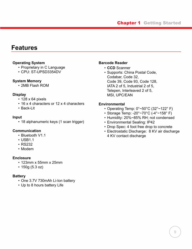
Features
Operating System • Propr�etary �n C Language • CPU: ST-UPSD3354DV System Memory • 2MB Flash ROM
Display • 128 x 64 pixels • 16 x 4 characters or 12 x 4 characters • Back-L�t
Input • 18 alphanumer�c keys (1 scan tr�gger)
Communication • Bluetooth V1.1 • USB1.1 • RS232 • Modem
Enclosure • 123mm x 55mm x 25mm • 150g (5.3 oz)
Battery • One 3.7V 730mAh L�-Ion battery • Up to 8 hours battery L�fe
Barcode Reader • CCD Scanner • Supports: Ch�na Postal Code, Codabar, Code 32, Code 39, Code 93, Code 128, IATA 2 of 5, Industr�al 2 of 5, Telepen, Interleaved 2 of 5, MSI, UPC/EAN
Environmental • Operating Temp: 0°~50°C (32°~122° F) • Storage Temp: -20°~70°C (-4°~158° F) • Humidity: 20%~85% RH; not condensed • Env�ronmental Seal�ng: IP42 • Drop Spec: 4 foot free drop to concrete • Electrostat�c D�scharge: 8 KV a�r d�scharge 4 KV contact d�scharge
Chapter 1 Getting Started
10
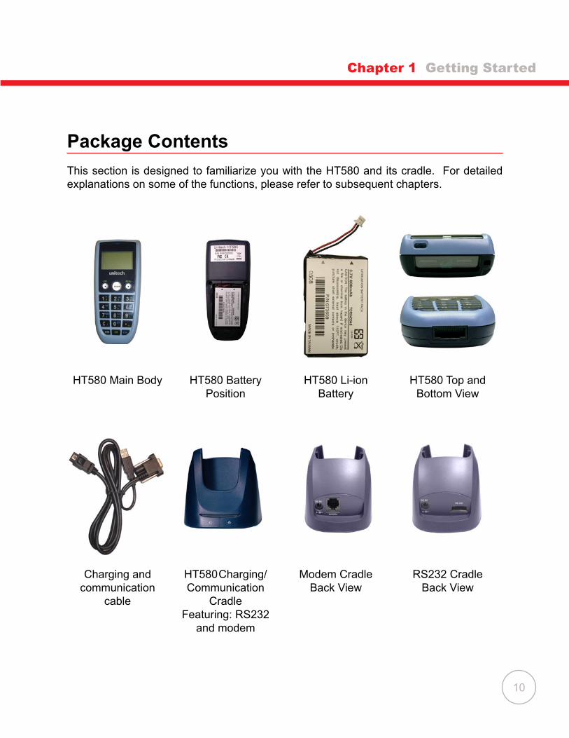
HT580 Ma�n Body HT580 Battery Pos�t�on
HT580 L�-�on Battery
HT580 Top and Bottom V�ew
Charg�ng and commun�cat�on
cable
HT580 Charg�ng/Commun�cat�on
CradleFeatur�ng: RS232
and modem
Modem Cradle Back V�ew
RS232 Cradle Back V�ew
Package Contents
Th�s sect�on �s des�gned to fam�l�ar�ze you w�th the HT580 and �ts cradle. For deta�led explanat�ons on some of the funct�ons, please refer to subsequent chapters.
Chapter 1 Getting Started
11
Battery Storage and Safety Precautions
Chapter 1 Getting Started
Batter�es should be stored at normal room temperature. Avo�d plac�ng them �n any s�tuat�on where explos�on or damage could poss�bly occur. The L�-Ion batter�es may lose the�r charge �f not used for several months due to back up and �nternal res�stance. If th�s happens, we suggest recharg�ng pr�or to use.
Remove Main Battery
To remove the ma�n battery, press down on the release button wh�le push�ng out the cover on the un�t. We suggest that the battery not be removed, �f poss�ble.
Charging
When start�ng to operate the HT580, the ma�n battery must be fully charged before the first use. The HT580 is equipped with a 3.7V 730mAh Lithium-Ion battery. For charg�ng, use the 5 volt AC adaptor and the RS232 commun�cat�on cable. It takes 8 hours to fully charge the ma�n battery when empty. We suggest users recharge the battery regularly after long hours of use.
Powering the HT580 On/Off
To power the HT580 on make sure that the battery has been charged accord�ngly (see page 11). Hold down the power button for a second. The screen on the HT580 w�ll flash and the unit will go through a power-up process to load the screen, Autorun, and battery status.
To power the HT580 off hold down the power button for 3-seconds. The un�t has a secur�ty feature that requ�res �t be held down for 3-seconds so that un�t �s not acc�dentally shut off wh�le �t �s �n use.
Th�s �con shown �n the menu �nd�cates the current battery capac�ty status.
12
Chapter 1 Getting Started
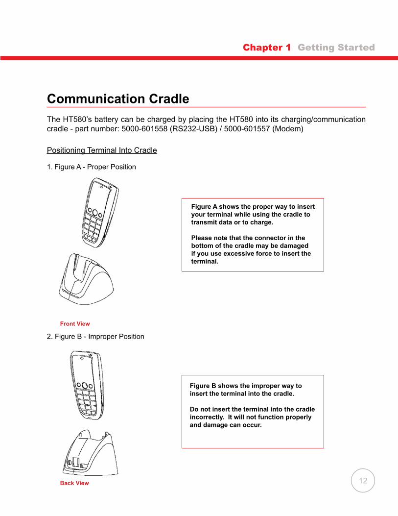
Front View
2. F�gure B - Improper Pos�t�on
Figure A shows the proper way to insert your terminal while using the cradle to transmit data or to charge.
Please note that the connector in the bottom of the cradle may be damaged if you use excessive force to insert the terminal.
Figure B shows the improper way to insert the terminal into the cradle.
Do not insert the terminal into the cradle incorrectly. It will not function properly and damage can occur.
Communication Cradle
The HT580’s battery can be charged by plac�ng the HT580 �nto �ts charg�ng/commun�cat�on cradle - part number: 5000-601558 (RS232-USB) / 5000-601557 (Modem)
Pos�t�on�ng Term�nal Into Cradle
1. F�gure A - Proper Pos�t�on
Back View

13
Chapter 1 Getting Started
Communication Cradle LED IconsTh�s LED l�ght (Red) shows the power status of the cradle �tself. An Illum�nated l�ght �nd�cates the cradle �s charg�ng. To �dent�fy �f the term�nal �s fully charged, �t may be necessary to check the term�nal LCD.
Th�s LED l�ght (Green) shows transm�ss�on status of the cradle �tself. An �llum�nated l�ght �nd�cates that data �s �n transm�ss�on.
HT580 Communication with the Host
Interface Port
The HT580 commun�cates v�a the RS232 commun�cat�on port located on the bottom of the un�t. You can connect the HT580 d�rectly v�a the commun�cat�on cable to your PC’s RS232 port for data transfer, or connect v�a the cradle.
Pin AssignmentPin Name Pin Name
1 US-POWER 7 DSR
2 GND 8 GND
3 DC-IN 9 DTR
4 USB DP 10 TXD
5 CTS 11 RXD
6 RTS 12 USB DP
USB client 1.1 connection through cable
RS232/Modem Cradle Communication

14
HT580 Keypad
The HT580 keypad consists of 18 rubber keys and one power key. The keypad is configured �nto three d�fferent modes: Numer�c mode, Command mode, and Alphabet�c mode.
The keypad is configured in Numeric mode by default, Command mode when the light green CMD key �s selected, or Alphabet�c mode when the blue ALPHA key �s selected.
Keypad DescriptionTo power on the un�t press the power key located on the top r�ght cover of the dev�ce.
ESC Returns you back to the prev�ous menu.
MENU Press MENU to scroll �tems you requ�re.
SCAN Press SCAN to tr�gger scann�ng funct�on or to perform as the ENTER key wh�le �n Setting mode.
C Press C to delete.
ENTER Press ENTER to save changes or to go to the next page.
ALPHA Press ALPHA to sw�tch to Alphabet. Any alphabet�cal character (�n blue pr�nt) can be act�vated w�th the ALPHA key
CMD Press CMD to perform del�m�ters such as “#”, “$”, etc. Any del�m�ter (pr�nted �n green) can be act�vated w�th the CMD key.
Using the Hardware
Chapter 2

15
Operating the HT580
After power�ng on the HT580, you w�ll see the Ma�n Menu as below:
There are 3 opt�ons: Sett�ng, Term�nal, and Run EasyJob.
NOTE: The 3rd opt�on “3. RUN EASYJOB” w�ll only be d�splayed �f the dev�ce conta�ns an EasyJob Program. Please refer to the EasyJob Manual for more �nformat�on.
HT580 V1.151. SETTING2. TERMINAL3. RUN EASYJOB
Chapter 2 Using the Hardware
Barcode Scanning Spectrum

16
Setting the Date/Time
Setting SystemThe Sett�ng menu does 2 major funct�ons – User Mode sett�ngs and Superv�sor
sett�ngs.
S�nce barcode scann�ng �s d�sabled �n menu mode, the SCAN key �s used as the ENTER key. Wh�le on Sett�ng mode, the user can use the follow�ng two ways to select any �tem.
• Press the MENU key to move to the target �tem and then press the SCAN/ENTER key• D�rectly press the �tem number assoc�ated w�th the sett�ng, to enter the sett�ng opt�ons
After select�ng the Sett�ng menu from the ma�n screen, there are four sett�ng opt�ons:
DATE & TIMEThe Date & T�me page w�ll appear as �t �s shown below:
Press numer�c keys to �nput correct date and t�me. Once complete, press ENTER to save the rev�sed sett�ngs. To return to the prev�ous menu, press ESC.
YYYY-MM-DD2000-01-08HH-MM-DD05:50:35
1. DATE & TIME2. DEVICE3. MODEM4. SUPERVISOR
Chapter 2 Using the Hardware

17
Device Settings
Dev�ce sett�ngs are the HT580’s bas�c sett�ngs as shown �n menu below.
Backlight
The HT580’s backl�ght can be turned on automat�cally after a key �s pressed, and �t w�ll automatically turn off after predefined period time if no keys are pressed. The time-out per�od w�ll be reset �f any keys are pressed. In the HT580, the t�me-out per�od can be set to 10, 20, 30 or 60 seconds. The backlight can also be set to always off, or always on.
Use the MENU button to adjust sett�ng. Below are the opt�ons you may choose.
ITEM DESCRIPTIONON 10 SECS The backl�ght turns on after press�ng a key, and turns off
automat�cally after 10 secondsON 20 SECS The backl�ght turns on after press�ng a key, and turns off
automat�cally after 20 secondsON 30 SECS The backl�ght turns on after press�ng a key, and turns off
automat�cally after 30 secondsON 60 SECS The backl�ght turns on after press�ng a key, and turns off
automatically after 60 secondsAlways Backl�ght always stays onOff Backl�ght always stays off
1. BACKLIGHT2. SCANNER3. AUTORUN 4. MEM5. BUZZER 6. KEY
Chapter 2 Using the Hardware
18
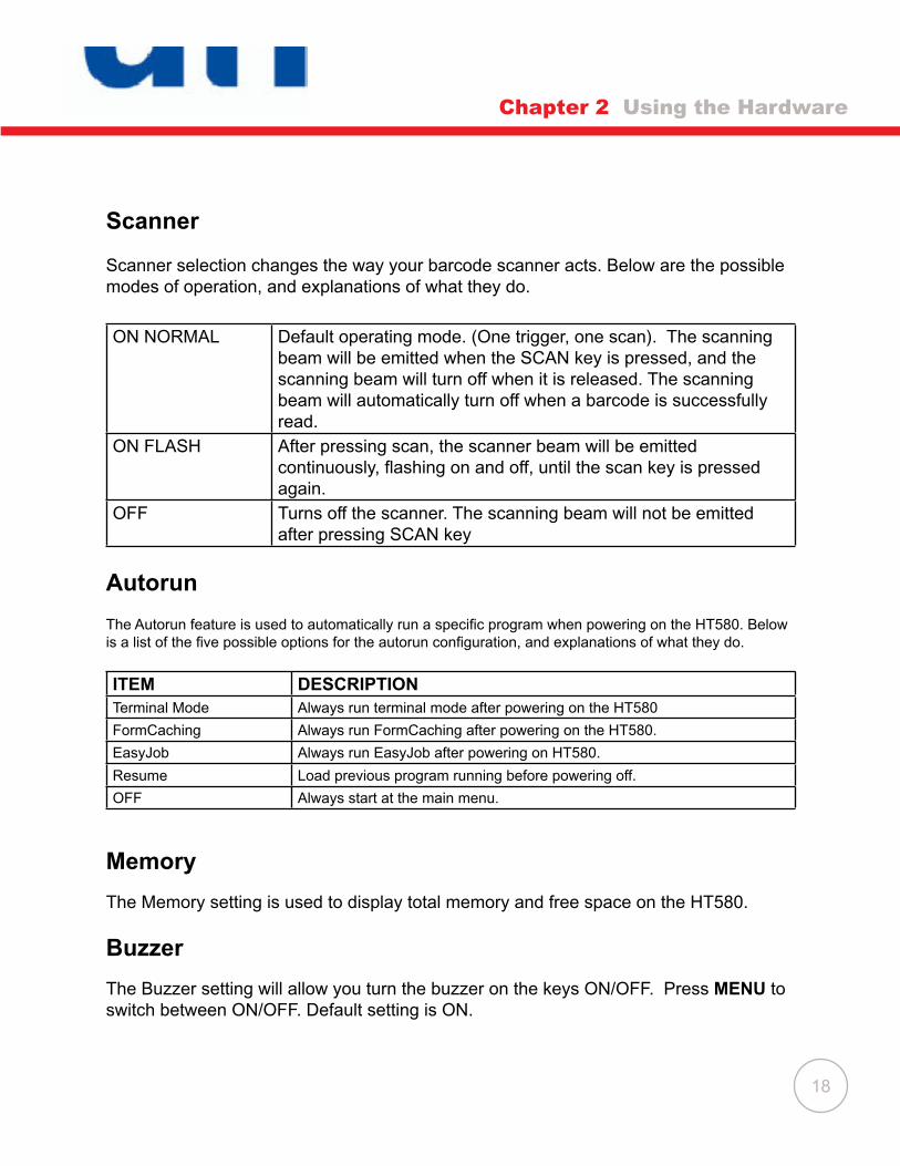
Scanner
Scanner select�on changes the way your barcode scanner acts. Below are the poss�ble modes of operat�on, and explanat�ons of what they do.
ON NORMAL Default operat�ng mode. (One tr�gger, one scan). The scann�ng beam w�ll be em�tted when the SCAN key �s pressed, and the scann�ng beam w�ll turn off when �t �s released. The scann�ng beam w�ll automat�cally turn off when a barcode �s successfully read.
ON FLASH After press�ng scan, the scanner beam w�ll be em�tted continuously, flashing on and off, until the scan key is pressed aga�n.
OFF Turns off the scanner. The scann�ng beam w�ll not be em�tted after press�ng SCAN key
Autorun
The Autorun feature is used to automatically run a specific program when powering on the HT580. Below is a list of the five possible options for the autorun configuration, and explanations of what they do.
ITEM DESCRIPTIONTerm�nal Mode Always run term�nal mode after power�ng on the HT580
FormCach�ng Always run FormCach�ng after power�ng on the HT580.
EasyJob Always run EasyJob after power�ng on HT580.
Resume Load prev�ous program runn�ng before power�ng off.
OFF Always start at the ma�n menu.
Memory
The Memory sett�ng �s used to d�splay total memory and free space on the HT580.
Buzzer
The Buzzer sett�ng w�ll allow you turn the buzzer on the keys ON/OFF. Press MENU to sw�tch between ON/OFF. Default sett�ng �s ON.
Chapter 2 Using the Hardware

19
Key
The Key sett�ng �s used to sw�tch the funct�onal�ty of the ENTER key, w�th that of the ESCAPE key. Once th�s sett�ng �s enabled, the ESCAPE key w�ll act as the ENTER key, and the ENTER key w�ll act as the ESCAPE key.
Modem
Un�tech prov�des a modem cradle as an accessory for the HT580. W�th the cradle, a user can transfer data through the phone l�ne.
In general, a system adm�n�strator needs to setup a host PC to automat�cally d�al out to the modem cradle and �ssue the command for e�ther data commun�cat�on or remote control. For such configuration, it is necessary to setup the device to automatically pick the phone up when the host calls the modem. Th�s �s done w�th the “AUTO ANSWER” opt�on.
The user can also d�rectly call the remote host PC from the modem cradle v�a the HT580. To do th�s, �t �s necessary to set up the remote PC’s phone number �n the HT580.
Below �s a l�st of the opt�ons for modem sett�ngs and a descr�pt�on of what they do.
ITEM DESCRIPTIONPHONE NUMBER To set up the remote PC’s phone numberAUTO ANSWER Send ATS0=1 [enter] to modem cradle. The modem cradle w�ll
automat�cally p�ck up the phone after one r�ng tone. You w�ll get an error message �f HT580 �s not plugged �nto the cradle or �f the modem cradle �s powered off.
DIAL OUT D�al Out calls the host PC. The PC must wa�t for a phone call.HANG UP Hangs up the phone call �f the HT580 �s connected.
Chapter 2 Using the Hardware
20
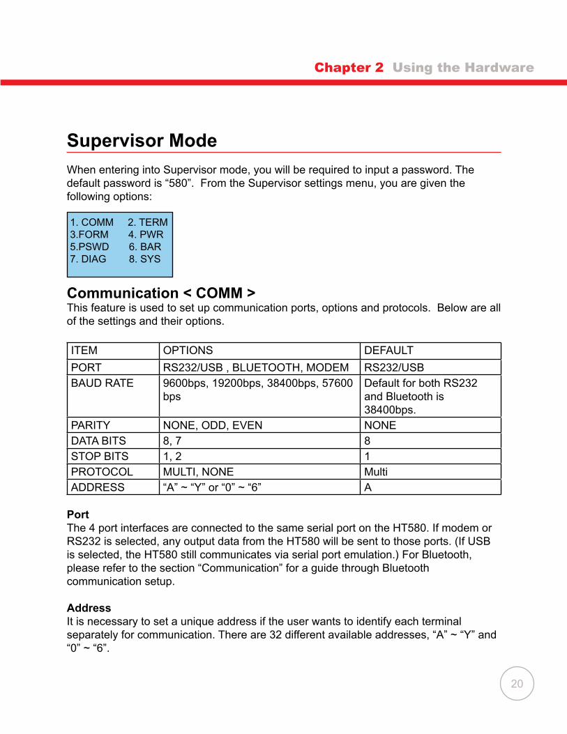
Supervisor Mode
When enter�ng �nto Superv�sor mode, you w�ll be requ�red to �nput a password. The default password �s “580”. From the Superv�sor sett�ngs menu, you are g�ven the follow�ng opt�ons:
Communication < COMM > Th�s feature �s used to set up commun�cat�on ports, opt�ons and protocols. Below are all of the sett�ngs and the�r opt�ons.
ITEM OPTIONS DEFAULT
PORT RS232/USB , BLUETOOTH, MODEM RS232/USBBAUD RATE 9600bps, 19200bps, 38400bps, 57600
bpsDefault for both RS232 and Bluetooth �s 38400bps.
PARITY NONE, ODD, EVEN NONEDATA BITS 8, 7 8STOP BITS 1, 2 1PROTOCOL MULTI, NONE Mult�ADDRESS “A” ~ “Y” or “0” ~ “6” A
PortThe 4 port �nterfaces are connected to the same ser�al port on the HT580. If modem or RS232 �s selected, any output data from the HT580 w�ll be sent to those ports. (If USB �s selected, the HT580 st�ll commun�cates v�a ser�al port emulat�on.) For Bluetooth, please refer to the sect�on “Commun�cat�on” for a gu�de through Bluetooth commun�cat�on setup.
AddressIt �s necessary to set a un�que address �f the user wants to �dent�fy each term�nal separately for communication. There are 32 different available addresses, “A” ~ “Y” and “0” ~ “6”.
Chapter 2 Using the Hardware
1. COMM 2. TERM3.FORM 4. PWR 5.PSWD 6. BAR7. DIAG 8. SYS

21
Chapter 2 Using the Hardware
Protocol To commun�cate w�th Un�tech’s PT ser�es dev�ces, the HT580 prov�des mult�-protocol. Please refer to the commun�cat�on sect�on and mult�-protocol for more deta�ls.
NOTE: HT580’s built-in Bluetooth modem is fixed at 38400bps. If the user changes the port opt�on to Bluetooth, the baud rate w�ll automat�cally be changed to 38400bps.
Terminal < TERM >
The TERM command enables the HT580 to run a bu�lt-�n Term�nal emulator. The HT580 w�ll operate as a dumb ASCII term�nal when the user select th�s feature and d�sable the Formcach�ng menu.
To change the commun�cat�on sett�ngs of Term�nal Mode, proceed to the Supervisor Mode and enter Term Setup. When finished, go to the Ready Mode menu and press 2.
Terminal IDEach HT580 “Terminal” can be identified by an 8-character string Terminal ID assigned by the user. In�t�ally, the default ID �s “HT580”. Val�d characters for ass�gn�ng Term�nal ID are alphanumer�c characters (‘A’-’Z’, ‘0’-’9’). H�t ENTER to make the select�on.
OnlineUse the [ ] key to toggle between below 3 modes, then h�t ENTER to make the select�on.
ITEM DESCRIPTIONLOCAL The HT580 does not transm�t gathered data to
RS232/USB/Bluetooth.REMOTE NONE The HT580 w�ll output data gathered from the bar code port or
keypad to �ts RS- RS232/USB/Bluetooth w�th None protocol.REMOTE MULTI The HT580 w�ll output data gathered from the bar code port or
keypad to �ts RS- RS232/USB/Bluetooth w�th Mult�-Protocol.
Echo Use the [ ] key to toggle between ON and OFF, then h�t ENTER to make the select�on. The collected data w�ll be d�splayed on the HT580 LCD when Echo �s set to ON, otherw�se data w�ll not be d�splayed when �t �s set to OFF.
22
AutoLF Use the [ ] key to toggle between ON or OFF, then h�t ENTER to make the select�on. When AutoLF �s set to ON, the HT580 w�ll append a LF (10 hex) character to the �nput data block.
Mode Use the [ ] key to toggle between BLOCK and CHAR, then h�t ENTER to make the select�on.
Line/Page Use the [ ] key to toggle among LINE, PAGE and BOTH, then h�t ENTER to make the select�on.
FormCaching < FORM >
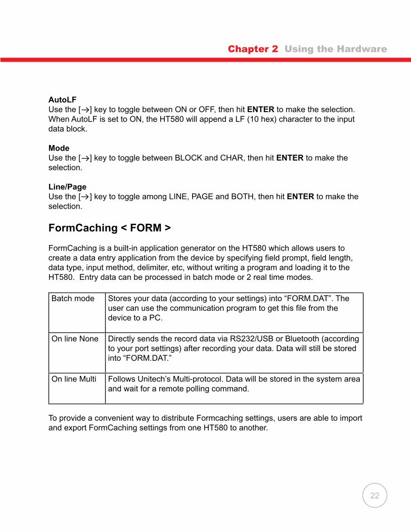
FormCach�ng �s a bu�lt-�n appl�cat�on generator on the HT580 wh�ch allows users to create a data entry application from the device by specifying field prompt, field length, data type, �nput method, del�m�ter, etc, w�thout wr�t�ng a program and load�ng �t to the HT580. Entry data can be processed �n batch mode or 2 real t�me modes.
Batch mode Stores your data (accord�ng to your sett�ngs) �nto “FORM.DAT”. The user can use the communication program to get this file from the dev�ce to a PC.
On l�ne None D�rectly sends the record data v�a RS232/USB or Bluetooth (accord�ng to your port sett�ngs) after record�ng your data. Data w�ll st�ll be stored �nto “FORM.DAT.”
On l�ne Mult� Follows Un�tech’s Mult�-protocol. Data w�ll be stored �n the system area and wa�t for a remote poll�ng command.
To prov�de a conven�ent way to d�str�bute Formcach�ng sett�ngs, users are able to �mport and export FormCach�ng sett�ngs from one HT580 to another.
Chapter 2 Using the Hardware

23
Chapter 2 Using the Hardware
When �n sett�ng mode, there are 3 opt�ons – SETTING, IMPORT and EXPORT as shown �n menu below.
EXPORT Saves FormCaching’s configuration as “FORM.SET”. IMPORT Changes FormCaching configuration from the “FORM.SET” file.SETTING Configures FormCaching‘s operation flow.
When SETTING is selected, the HT580 will first ask the user to specify data fields in four categories, including field prompt, data length, data type and device type. After defining all of the data field options, use the ESC key to end the setup. Below �s a table descr�b�ng all of the FormCach�ng Sett�ng opt�ons.
FormCaching Specification
DATA FIELD DEFINITION: maximum field number= 8Category Range Descr�pt�onFIELD PROMPT Max.16 characters set field promptingMIN/MAXF�eld LENGTH
1-48 Set m�n�mum and max�mum field length
F�eld type 1.NUMERIC2.ALPHANUM
Numeric data (0~9) or alphanumer�c data (20H~FCH)
DEVICE TYPE 1.KEY ONLY2.SCAN ONLY3.BOTH
Input by keyboard only, bar code scann�ng only or both
1. SETTING2. IMPORT3. EXPORT

24
Chapter 2 Using the Hardware
DATA RECORD DEFINITIONCategory Range Descr�pt�onBetween F�eld 1. Append Screen
2. Clear Screen1. Append Screen: Prompt w�ll be d�splayed on next l�ne accord�ng to prev�ous cursor place. If cursor �s already on the last l�ne, �t w�ll scroll one l�ne up.2. Clear Screen: It w�ll clear screen and then d�splay
FIELD DELIMITER 1. , 2. ;3. SPACE 4. TAB5. FIXED LENGTH
Assign field delimiter, “Fixed Length” mean to store data accord�ng to max� length sett�ng, �t w�ll automat�cally append spaces to end of field data if length of �nput data are less than max�. length
RECORD DELIMITER 1. CR2. LF3. CRLF
Ass�gn record del�m�ter
DATE STAMP FIELD 1. NONE 2. MMDD 3. YYYYMMDD4. DDMMYY5. YYYYMMDD6. DDMMYYYY
Ass�gn date stamp and spec�fy the format of date stamp
TIME STAMP FIELD 1. NONE 2. HHMM3. HHMMSS 4. SSMMHH
Ass�gn t�me stamp and spec�fy the format of t�me stamp
Trans Mode 1. Batch 2. Onl�ne None3. Onl�ne Mult�
Defines the way your data is stored
FIELD DELAY 0-6 Spec�fy t�me delay between each record �nput �n second

25
Chapter 2 Using the Hardware
When FormCaching is enabled, a data file named FORM.DAT will be created in the HT580. FORM.DAT stores the data as entered by the user when us�ng the FormCaching program. The HT580 will not allow the user to redefine the data fields in FormCaching once the FORM.DAT has been created. The file FORM.DAT must be deleted in order to implement any change in the configuration of FormCaching.
Running FormCachingThe HT580 bu�lt-�n appl�cat�on FormCach�ng can be run from the ma�n menu by select�ng the term�nal opt�on, then select�ng 2. Formcach�ng. The FormCach�ng application will follow the prompt settings previously defined by the user to request input, and stores the data in the FORM.DAT file.
HT580 FormCaching Defaults The HT580 enables FormCach�ng w�th the default sett�ngs:
DATA FIELD DEFINITION: F�eld number=2Category Sett�ng
F�eld #1 FIELD PROMPT ITEM:DATA LENGTH 20FIELD TYPE ALPHANUMDEVICE TYPE BOTH
F�eld #2 FIELD PROMPT QTY:DATA LENGTH 8DATA TYPE ALPHANUM
DATA RECORD DEFINITIONCategory Sett�ngFIELD DELIMITER ,RECORD DELIMITER CRDATE STAMP FIELD NONETIME STAMP FIELD NONEFIELD DELAY 1

26
Chapter 2 Using the Hardware
Power < PWR >
The un�t w�ll automat�cally power off �f noth�ng �s scanned or keyed after the set amount of t�me. Use the MENU key to set the auto-off t�me-out to 1, 2, 5, 10, or 15 m�nutes, select DISABLE to d�sable the auto power-off
Password <PSWD>
The Password Sett�ng allows the user to change the default password. The default password �s “580”
Barcode < BAR >
This option is used to configure individual barcode symbologies. After entering the configuration menu, the LCD will display the BARCODE Setup as shown below.
Setup decod�ng of HT580 supported bar code symbolog�es:
Symbology Function Option DefaultCode 39 Decod�ng ON/OFF ON
full ASCII ON/OFF OFFCheck D�g�t ON/OFF OFFStart/stop Character Send/No-send NO SEND
I 2 of 5 Decod�ng ON/OFF ONCheck D�g�t ON/OFF OFFF�rst d�g�t SEND/NOT SEND SENDLast d�g�t SEND/NOT SEND SEND
Code 32 Decod�ng ON/OFF ONF�rst d�g�t SEND/NOT SEND SENDLast d�g�t SEND/NOT SEND SEND
<BARCODE SETUP>CODE 39ON

27
Symbology Function Option DefaultMatr�x 2 of 5 Decod�ng ON/OFF ON
Check D�g�t ON/OFF OFFIndustr�al 2 of 5 Decod�ng ON/OFF ONCodabar Decod�ng ON/OFF ON
Check D�g�t ON / ON&Not Send / ON & SEND / OFF
OFF
CHINA POST Decod�ng ON/OFF ONCheck D�g�t ON / ON&Not Send / ON & SEND /
OFFOFF
MSI Decod�ng ON/OFF OFFCHECK DIGIT MOD
SINGLE MOD 10/DOUBLE MOD 10/DOUBLE MOD 11+10
SINGLE MOD 10
Check D�g�t ON & Send / ON & NOT SEND OFFIATA 2 of 5 Decod�ng ON/OFF OFF
Check D�g�t ON / ON &Not Send / ON&SEND / OFF OFFCODE 11 Decod�ng ON/OFF OFF
Check D�g�t ON / ON&Not Send / ON&SEND / OFF OFFEAN-13 Decod�ng ON/OFF ON
ISBN ON/OFF OFFISBN ON/OFF OFFLead�ng D�g�t Send/No-send SendCheck D�g�t Send/No-send Send
EAN-8 Decod�ng ON/OFF ONLead�ng D�g�t SEND/NOT SEND SendCheck D�g�t SEND/NOT SEND Send
UPC-A Decod�ng ON/OFF ONEXPEND to EAN-13
ON/OFF OFF
Lead�ng D�g�t ON/OFF SendCheck D�g�t ON/OFF Send
Chapter 2 Using the Hardware

28
Symbology Function Option DefaultUPC-E Decod�ng ON/OFF ON
UPC-E0 ON/OFF ONUPC-E1 ON/OFF ONEXPEND TO UPC-A
ON/OFF OFF
Lead�ng D�g�t SEND/NOT SEND SendCheck D�g�t SEND/NOT SEND Send
CODE 93 Decod�ng ON/OFF OFFCode 128 Decod�ng ON/OFF ON
EAN128 ON/OFF ONEAN128 CODE ID
ON/OFF OFF
EAN128 FUNC CH
NOT SEND/SEND NOT SEND
Telepen Decod�ng ON/OFF ONUK PLESSEY Decod�ng ON/OFF OFF
Check D�g�t SEND/NOT SEND Send
Chapter 2 Using the Hardware

29
Diagnostic <Diag>
The HT580 has a bu�lt-�n d�agnost�cs program to test the term�nal’s hardware. The test rout�nes are data destruct�ve. Therefore, before runn�ng the d�agnost�c program, make sure you back up the data on the HT580.
NOTE: When a hardware or software serv�ce has been made on the HT850, such as ma�ntenance, repa�r or upgrade, �t �s strongly recommended to run the d�agnost�c program.
ITEM DESCRIPTIONVER Display firmware version for the HT580 and Decoder.SCAN Tests barcode �nput by scann�ng barcode labels. Press the ESC key to
return to the d�agnost�cs menu.LCD Darken the dots of the LCD screen and cycle power to the LCD backl�ght
to check �f the LCD funct�ons OKCOMM Connect to the PC’s commun�cat�on test�ng program to test the USB/
RS232 commun�cat�onPWR Tests Battery powerKEY Tests every key responseRTC Current t�me/date �s d�splayedMEM Tests RAM cond�t�on
Chapter 2 Using the Hardware
1. VER 2. SCAN3. LCD 4. COMM5. PWR 6. KEY7. RTC 8. MEM

30
System <SYS>
There are 4 opt�ons g�ven �n the System menu as shown below – Warm Start, Cold Start, Update F/W and Update Decoder.
Warm Start Warm boots the HT580Cold Start Reboots the HT580, erasing all data and returning all configurations
to default.Update F�rmware Update firmware. (See page 38)
Update Dec Un�t must be sent �n to Un�tech for th�s update.
Another way to Cold/Warm start HT580 by comb�nat�on keys:
COLD START: Wh�le the un�t �s OFF. Press and hold the CMD/ALPHA keys and press the POWER key s�multaneously.
WARM START: Wh�le the un�t �s OFF. Press and hold the ALPHA key and press the POWER key s�multaneously.
FormCaching
After configuring the Formcaching you can press “2” from the main menu to enter Formcaching’s data input. Input data will be stored on the HT580 as the file “Form.dat”. You can use the commun�cat�on tool to upload �t back to PC. You can delete �t from the HT580 after �t has been successfully uploaded to PC.
1. WARM START2. COLD START3. UPDATE F/W4. UPDATE DEC
Chapter 2 Using the Hardware

31
Communication
Chapter 3
USB Communication
To connect the HT580 to PC v�a USB, you need to �nstall the USB dr�ver wh�ch w�ll red�rect data to a v�rtual COM port. You can get the USB dr�ver from HT580 CD.
Windows will prompt with the new device dialog box when the HT580 is first connected to the PC v�a USB. Please d�rect the d�alogue box to the Un�tech USB dr�ver folder and then follow �ts prompt�ng to �nstall the dr�ver.
Then, check for the correct COM port number from Control Panel System Hardware Device manager. Then you can find correct COM number from “USB Ser�al Port” under opt�on “Connect�on Port (COM and LPT)”
In the HT580, you should change the default commun�cat�on port to “RS232/USB” from Setting Supervisor COMM

32
Bluetooth Communication
To use Bluetooth commun�cat�on, you must change the HT580’s port sett�ng to Blue-tooth. To do th�s, go to from Setting Supervisor Comm Port
If there �s no Bluetooth support from your PC you should connect a USB Bluetooth dongle and �nstall the appropr�ate dr�vers. Then, cont�nue w�th the follow�ng steps:
1. Power on HT580 and then Run Bluetooth manager from PC
2. Cl�ck New Connection button
3. Select proper mode – Express Mode or Custom Mode. The user can spec�fy the COM port number �f select�ng custom mode
4.
Chapter 3 Communication

33
5. Search for all Bluetooth dev�ces w�th�n range and then l�st them on the screen. All of the HT580’s w�ll be d�splayed as “UNITECH” �n th�s screen. Cl�ck the Next button
6. You will be prompted to enter a PIN code. The HT580’s default PIN (Pass key) is “0580.” After enter�ng the PIN, your computer w�ll sync w�th the HT580 and w�ll be added to your dev�ces l�st. R�ght cl�ck the �con to connect �t.
7. You can also check the correct PORT number from “Deta�l”
NOTE: HT580’s BT Device name is fixed on “UNITECH”, so you will see a lots of “UNITECH” on Bluetooth Manager �f you want to connect several HT580’s to s�ngle PC. User may not be able to �dent�fy wh�ch one �s the correct HT580 to map to l�st, so �t �s suggested to power on one HT580 at a t�me when mak�ng a connect�on. Please note �ts MAC address from DETAIL.
Chapter 3 Communication

34
Communication Program
Easy Job �s also bundled w�th the commun�cat�on program “Mult�Ej”. To run Mult�Ej complete the follow�ng steps:
Locate the HT580 EasyJob Program folder as shown below.
You can also access Mult�EJ by go�ng to HT580 Easy Job. Select Tool Communication as below d�agram
Chapter 3 Communication

35
Mult�Ej program w�ll launch as shown below.
From here, you can:
• Drag and drop files from PC folder to HT580 directory to execute download function• Drag and drop files from HT580 directory to PC folder to execute upload function • Directly select files on HT580 directory area and delete.
Before us�ng Mult�Ej for commun�cat�on, you should setup the correct port number and commun�cat�on parameter by cl�ck�ng the Opt�ons �con on the menu bar.
Chapter 3 Communication
36
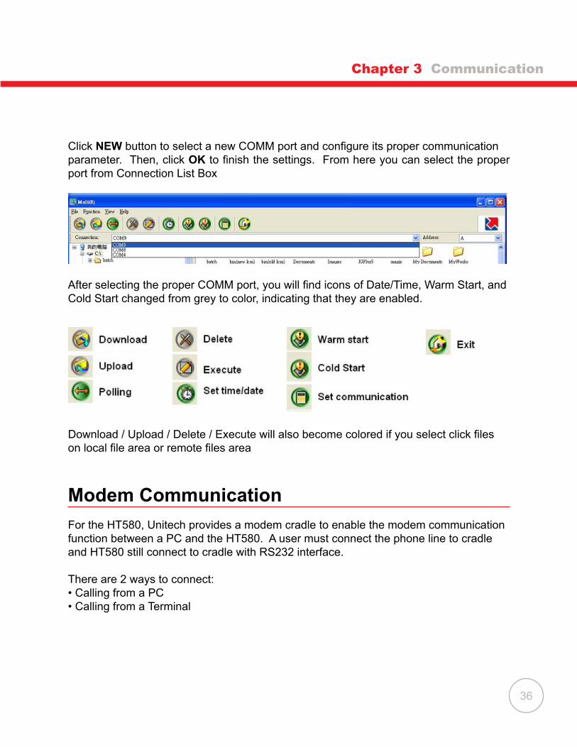
Cl�ck NEW button to select a new COMM port and configure its proper communication parameter. Then, cl�ck OK to finish the settings. From here you can select the proper port from Connect�on L�st Box
After selecting the proper COMM port, you will find icons of Date/Time, Warm Start, and Cold Start changed from grey to color, �nd�cat�ng that they are enabled.
Download / Upload / Delete / Execute will also become colored if you select click files on local file area or remote files area
Modem Communication
For the HT580, Un�tech prov�des a modem cradle to enable the modem commun�cat�on funct�on between a PC and the HT580. A user must connect the phone l�ne to cradle and HT580 st�ll connect to cradle w�th RS232 �nterface.
There are 2 ways to connect:• Call�ng from a PC• Call�ng from a Term�nal
Chapter 3 Communication

37
Calling from a PC
To call the modem from a PC, the HT580’s modem cradle should be set to automat�cally p�ck up an external call. Place the HT580 �nto the cradle w�th the cradle connected and powered on. Execute Setting Modem and then select AUTO ANSWER to let the HT580 send “ATS0=1” to the modem board. Then, the cradle can automat�cally p�ck up an external call after one r�ng tone. (After execut�ng “Auto Answer”, �t �s not recommended to power off the cradle, or the “Auto Answer” funct�on w�ll d�sable)
From the PC, you can use Mult�Ej to do a modem commun�cat�on w�th the HT580. You can set up the modem funct�ons from the opt�ons by check�ng “Modem”.
Follow�ng these steps, set up the correct In�t�al command and d�al the number.
Chapter 3 Communication
38
Calling from a Terminal
Currently, the HT580 can support dialing the modem from the firmware. EasyJob will prov�de modem funct�onal�ty �n the future.
On the PC s�de, you can use Mult�EJ or s�m�lar software to AutoAnswer. To do th�s, place the HT580 �nto the cradle and connect the phone l�ne. Then, follow the steps below:
• Execute Setting Modem Phone and �nput the correct phone number• Then, execute Setting Modem Dial out, to connect to remote dev�ce
To stop commun�cat�on, execute Setting Modem Hang, to hang up phone.
Updating Firmware
Unitech provides firmware as a zip file, which is named as “HT580Vx.xx.zip”. There are 8 files needed to complete the update: “bank0.bin” through “bank7.bin”.
You can get the latest firmware image from your supplier or contact Unitech directly. Firmware will be in a compressed zip file. You can use the MultiEJ to download those 8 files into the HT580. After the 8 files have been download into HT580, execute HT580’s Setting Supervisor SYS and then select 3.UPDATE F/W. The HT580 w�ll auto-matically update the firmware and cold start terminal.
Make sure the un�t �s charg�ng wh�le the update �s �n process to ensure the update completes successfully. Please refer to the sect�on “Commun�cat�on” for more deta�led information to transfer files to the HT580 from a PC.
Chapter 3 Communication